Fuzznoggin
-
Posts
49 -
Joined
-
Last visited
Content Type
Profiles
Forums
Gallery
Events
Everything posted by Fuzznoggin
-
 A question to those who may know...why were there dimples in the metal on one particular section of hull below the saddle tanks and slightly fore & aft of the tanks all about? I see them on some U-Boat photos but I cannot seem to find any reference material describing why they were like that. I believe I read a few days ago that it had something to do with the quality of the metal from the foundry. Curiosity has me befuddled.
 -
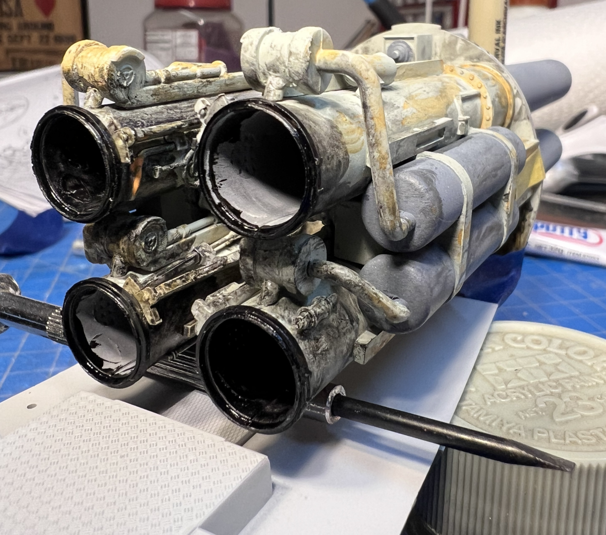
Photo Etch on the Bow Tubes This is where it get's dicey. I will start off with the bow door bulkheads. An excellent accompaniment to this kit but I will advise on some caution. The PE needs to be trimmed 1.5mm on the flat side for all 8 pieces or they will buckle when the hull haves are mated. There will be a good 2mm to 3mm gap in the bow seams if these are not trimmed. Shaded areas where the cuts were made and a piece of what was trimmed. The trimmed pieces in place Another view of the trimmed pieces. Inner doors were another challenge. Although the assembly went together just fine, the hinges just would not work as they impeded on the outer doors and in turn provided for zero room inside the hull for any space when the hull halves were mounted. I spent a lot of time trying to re-engineer this and just gave up. What I did do is adhere to the inner door to the outer door as close to the tube as possible. 3 of the tubes are open, 1 will be closed. This section of the kit itself isn't the best in engineering and I tend to think the outer doors might be slightly warped too. The aft tube section is a bit of a debacle. The instructions call for cutting a section out of the internal cone - wait!! There is no internal cone. In fact, it's just a torpedo tube sticking out of an empty chamber. Ok, so the way around this is to manufacture an internal cone (bulkhead) by cutting open the deck to gain access. I did not do that. Instead, I re-designed the hinge arrangement and attached it to the extended rod coming out of the aft pressure bulkhead. Looks good enough for me.


-
The RCSubs Photo Etch I shelved the Eduard PE because I found it lacked some of the hull details that RCSubs provide with their PE. One of those areas was the front grate array behind the dive plane. I had installed the aft grates but there wasn't any PE for the front. So let's continue this journey of fun and games with PE. Instruction Sheets set up A couple of sheets of PE in a box for easy access. Installation of the forward grates that were not included in the Eduard PE. There have been some who have cut this whole area out of the plastic. This is not necessary. Tape the PE in position and airbrush black. Remove the PE and you will have rows of black vent marks. Gently use the grout removal bit on your Dremel and cut out the rows of black vents top to bottom. Then adhere the PE in place. The uncut sections act as support beams and this works rather well. The aft grates installed. I found that the PCSubs was a bit bigger and had more detail than the Eduard. So I replaced the Eduard grates. Unfortunately, this section requires that you cut most of it out before adhering the PE. Saddle tank access panels. The clear side will require some of the PE hatches to be trimmed depending on how you design your view ports. 2 sets of screens here. One with black primer on it already ( did not cut out the area) and the round screen port that has been cut out. Custom made Happy Sawfish decal. The Captain approves. Some of the PE enhancements. I taped the inside of the tower to prevent spray into the Attack Periscope room. I will use the same technique on the clear section cut-outs of hull. Now before I'm corrected on this, yes I did install this on the wrong side intentionally. It has been moved back into it's correct position. Since the Conning Tower has been completely assembled, I will not be using the PE decking. I'll stick with what Trumpeter provided. I also will refrain from drilling out the main deck area. Instead I'll sand the decking down and then install the PE deck.


-
Cutting the Clear Sections For Viewing & Additional Items Cutting out the Clear plastic. Scary thought but actually it isn't that bad. I used a mini circular saw on a Dremel at the lowest speed possible. Take small bites at it. Don't run it as if you were cutting plywood. The tool still turns fast enough to cause melting clumps so go a little at a time and you will be ok. I started with the aft hull cone section. Rounded corners can be done using a Grout Removal bit (serrated type bit) with a Dremel. Slow and steady bites or your will chunk melted styrene. If you're unsure about tackling this, find some old model parts and give it a practice run. As you can see, with the clear plastic still intact, there is glare that detracts from the detail. Simply determine what you wish to view and use a marker to draw the area to be cut out. I would advise to cut inside the lines to allow for any corrections and sanding. Take it easy with small bites. Your end result will look like this when primed. Do the same for the remainder of the hull. Place all your modules into the port side then lay the clear side over that and trace out your viewing areas. The end result Time to add an additional member to the forward torpedo room. Some heating and bending require to position him properly. Dry fit test. Pretty happy with the positioning now. Time to paint him. The result


-
Continuation of Build Photos I apologize in advance for jumping around between areas on the build. There's a method behind my madness so to speak. So bear with me. I found that if you follow the instructions page by page you will screw something up. There are sections of the instructions that, to me, are a bit out sequence. Use good judgement and read the the instruction section beforehand and note what areas aren't essential to install right at that moment. Lighting Test I secured a lighting system from Small Scale Lighting in the UK. Simple & efficient, plus I like the individual pc boards which conveniently attach to each module. There are 2 modes - regular white lights on & the Alarm red/blue lights. As far as accuracy is concerned, I will plead artistic license to this one. Aft Torpedo / Electro Motor room Forward Torpedo Room Forward crew room / radio hydrophone room / head Control Room Aft Crew Room / Kitchen Control Room and Forward Engine Room Overall View


-
The Conning Tower & Attack Periscope Room The kit comes with the starboard hull molded in clear plastic but the conning tower has the port side molded in clear. Why, I can only guess. It doesn't seem right and it begged to be corrected. I basically had to cut out a viewing port on the starboard side. Now we are in business! A brief note: I had used Eduard's PE on the tower, then realized that it wasn't the look that I wanted. After assembling the tower I made the switch to RCsubs PE and I should have just purchased these to begin with. What you see here has the Eduard PE on it. There will be more photos of the tower in a future update. Starboard side with the corrected view port to the conning tower Inside views thru the view port Interior of attack periscope room during light test. Crew member coming up topside. Navigation lights added This portion of the assembly was tedious. Tolerances are minimal and paint needed to be scraped off slotted areas in order to fit properly. And now it's time to re-create Capt Willenbrock from Das Boot I am terrible with figures, but I think it turned out rather nicely. Just a test fit of all the conning tower figures. This is all coming together. One suggestion to all who are building or contemplating this build, refrain from adding exterior railing until the very last. There is no sense in installing it this early into the build and you will risk breaking pieces and regretting it. There will be more on the tower which will include photos with the RCsubs PE added.


- 15 replies
-
- 11
-

-
ELECTRO-MOTOR / AFT TORPEDO ROOM Moving on to the last main hull module. To me, it was the easiest of all the modules. Trumpeter's fit is rather good and does not forgive for painted areas at assembly points due to the precise tolerances. You will have to scrape off some paint in order to get the bulkheads, overheads, and decking to fit properly. I strongly suggest, as others do, to test fit often and frequently. Positioning figures. The left and right figures needed to be heated and bent into their proper positions. Figures painted. Each module itself tells a brief story. I will get to that later in the build log.


- 15 replies
-
- 11
-
-
Construction of the Engine Room bulkheads. The table legs come in photo etch and are extremely difficult to work with. I noticed a few builders who had issues trying to shape them properly. After a while of fighting with the PE, I elected to make my own legs. Artistic license if you will. We all remember Johann from Das Boot, right? Time to re-create that scene. There was a lot of heating and bending to get Johann in shape. Here I work on getting his right arm in the proper position with the valve stem being held to his ear. The completed figure. Meet Johann. Overall look at the final addition of Engine Room figures.


-
Main Engine Room Now were get into the detailing. The engine itself is colored "Hemp". This required a mixture which I will disclose tomorrow. Getting late here. Finally done! This is probably the most time consuming part of the build so far. Just take your time and weather it to make it look like it's been well used. There will be more photos of the Engine Room with the crew members in the next update.


-
Rear Crew Quarters / Kitchen Bulkheads assembled and weathered Kitchen light test Battery array under floor. Connections using old PE brass. No, not the mummies of Pompeii. LOL. Positioning crew before painting. Some had to be heated and bent into position. The result of those efforts. Note the book on the chest of the one sleeping sailor. Typical bulkhead art to break up the monotony. Module after completion


-
THE CONTROL ROOM This is where the creativity really begins. I decided to make the control room look like something was actually going on. Starting off with the overhead All the other items added and some weathering done Downloaded and resized a chart Scratch built a little navigation plotter. Now to start adding the weathering using washes of AK grease & grime and light rust. Added the crew to bring in the realism.


-
FORWARD CREW ROOM / RADIO / HYDROPHONE / HEAD Genereal assembly of the Forward Crew compartment. I know, I screwed up on the rails with the center bunks. One needs to pay attention to the numbers on the sprues. I didn't and ended up with the shorter rails added. But, good enough for government work, right? Hydrophone unit illuminated with a yellow nano LED. Radio panel, not visible but to the left, is also a nano LED illumination. The Head, weather to look like a well used truck stop toilet. Captain's quarters along with the radio / hydrophone rooms An overhead view of the module. Overhead view of the Head Radio/Hydrophione rooms. The white dial in radio room is illuminated with a nano-Led Battery array for under the Crew Room floor. Terminals joined by brass from old photo etch. Here is a light check of the radio panel Crew members installed. There will be much more to this later on in the build. Photos on walls were downloaded, resized, and tacked on to the bunk walls and bulkheads using sticky backed photo paper.


-
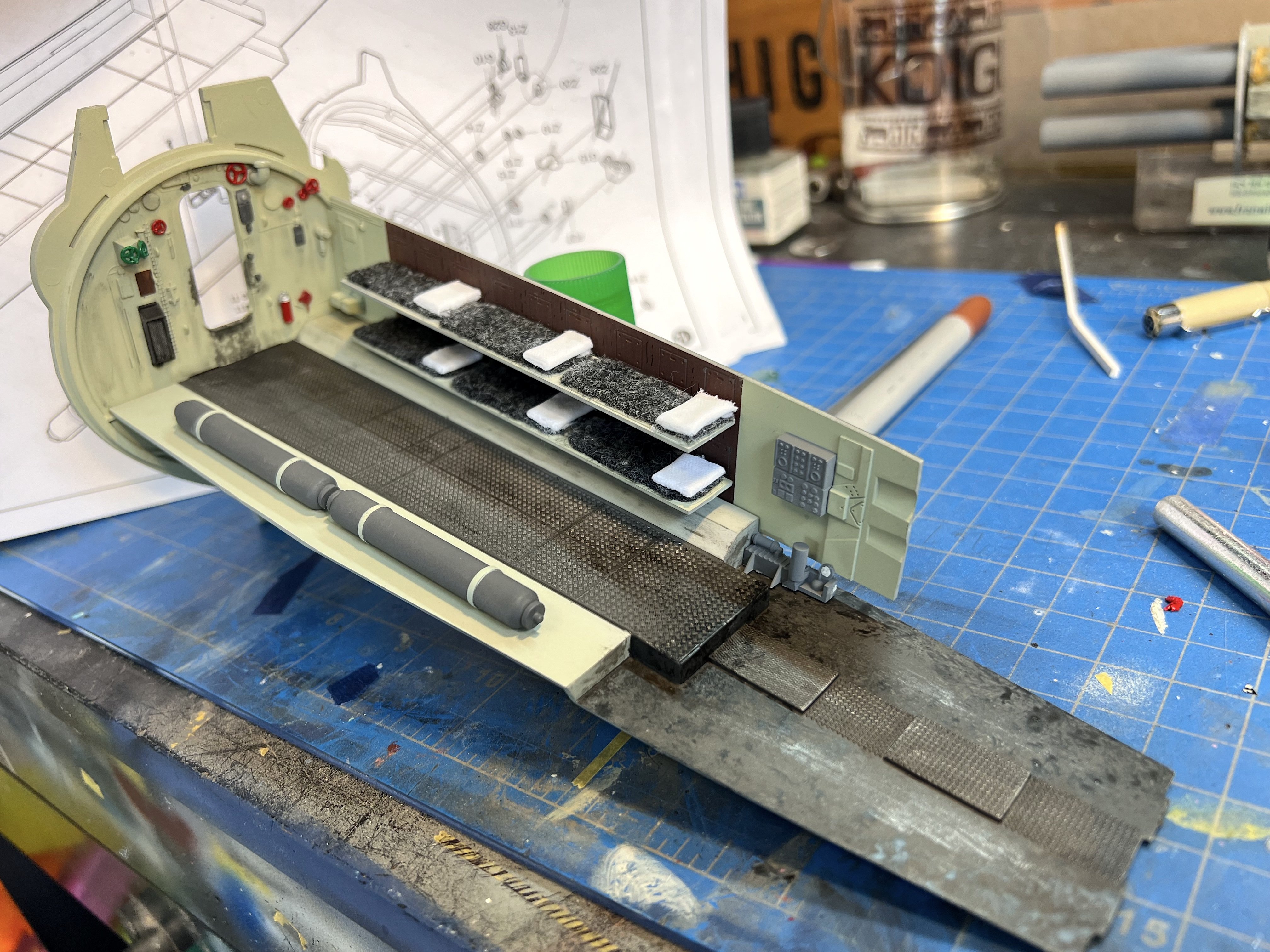
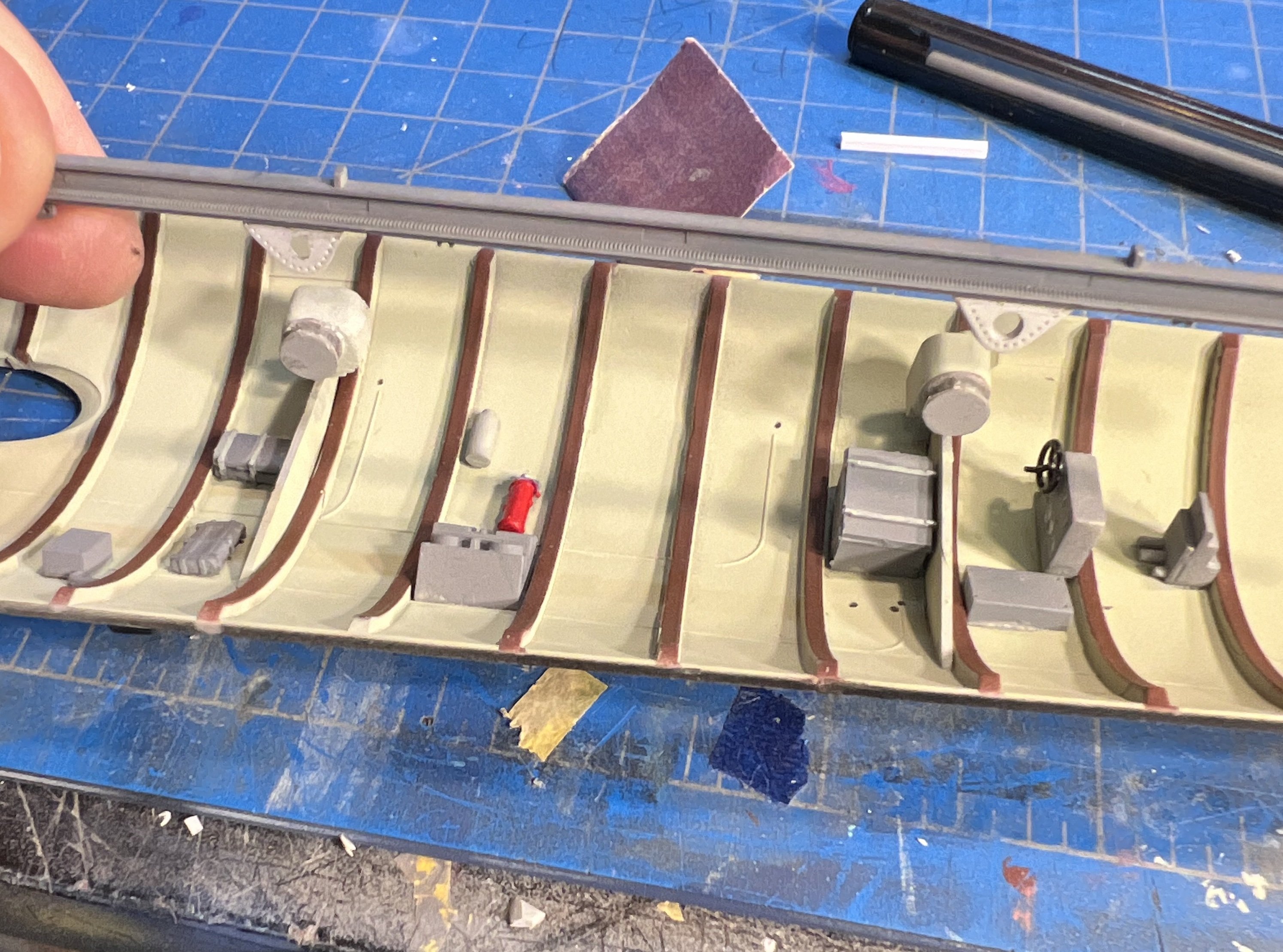
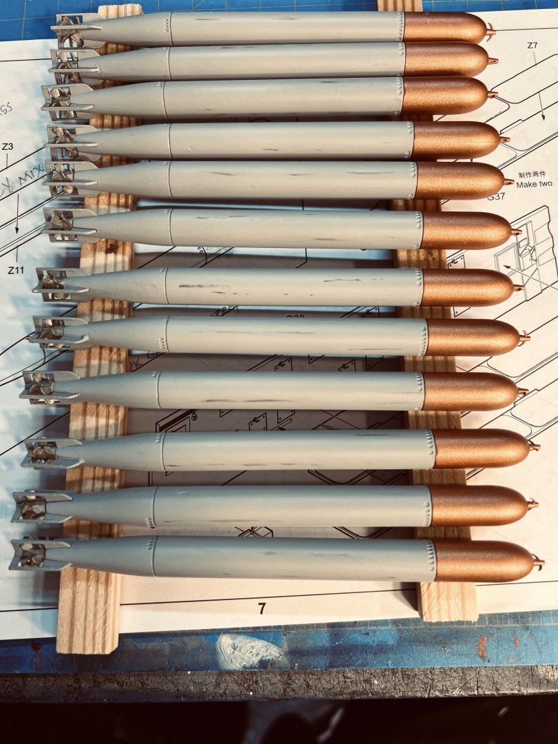
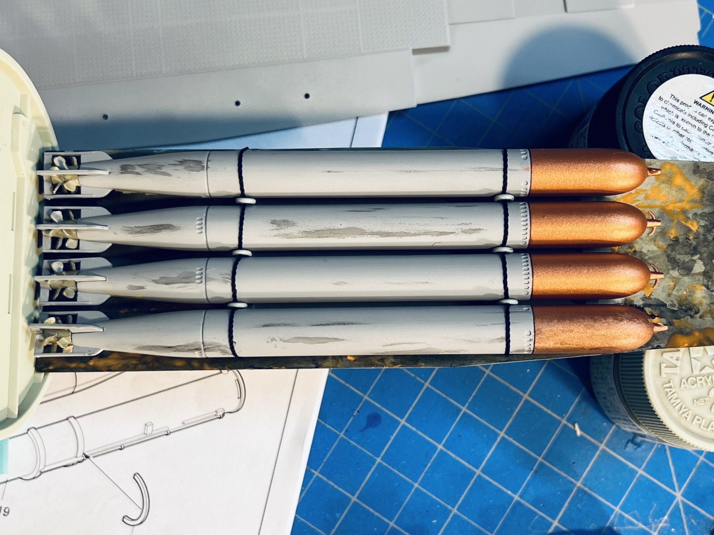
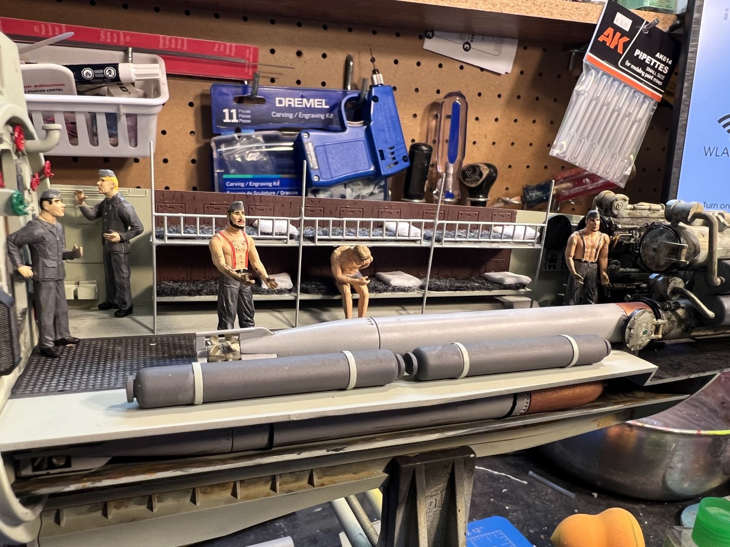
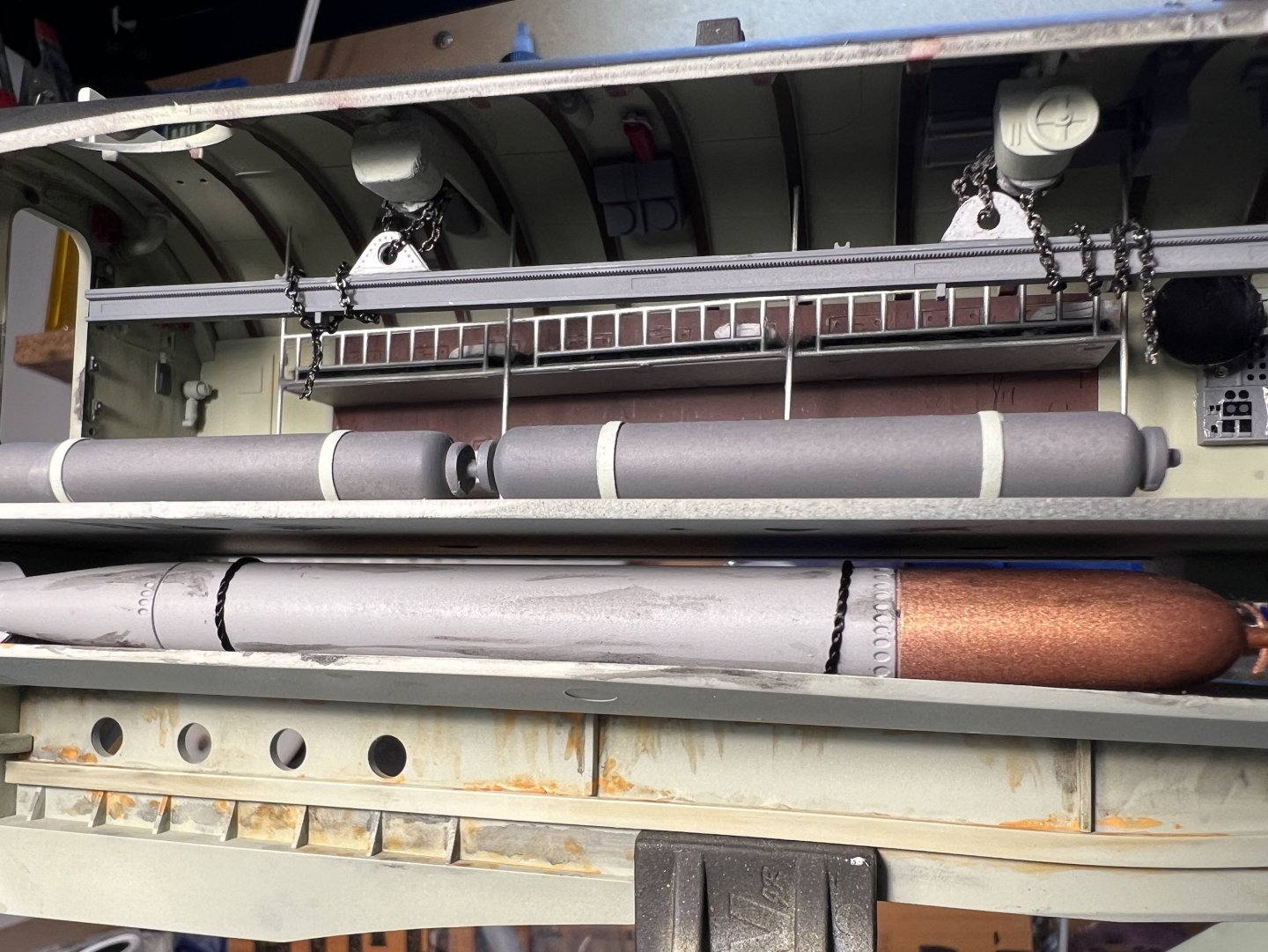
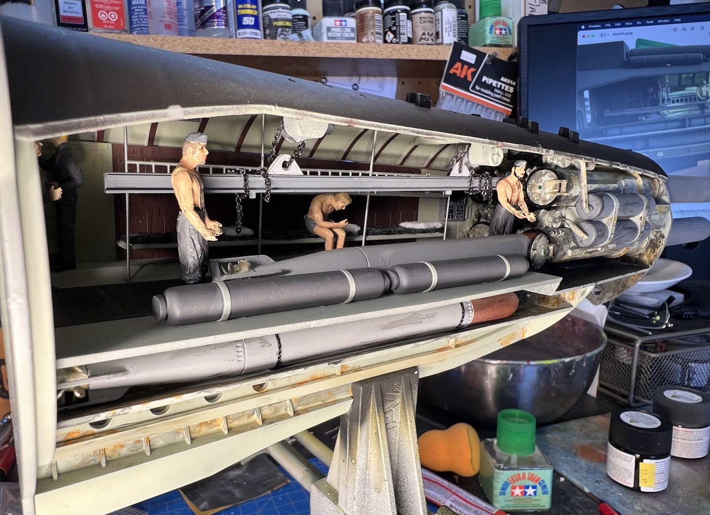
FORWARD TORPEDO ROOM I received this monster kit for Christmas 2023 and I'm heavily involved in its construction. I'll start off with the Forward Torpedo Room. Tamiya paints and AK weathering used exclusively. If you have any questions on anything, please ask and I will try to help you out the best I can. 12 "Eels" 4 spares arranged on lower tray below floor boards Forward tubes with their grease and other assorted yuck. Crew bunks with great felt and pillows made from folded white polyester. Floorboards weathered with AK bearing grease, panel liner, and ground up pastel chalks (brown & black). Crew members added You will need to scratch build a second winch unit to be used for the I-Beam on the overhead. Here, I used an ankle bracelet chain (courtesy of my wife) to use for the chains on the I-Beam torpedo lift. You can actually find these chains (ankle braclets) fairly cheap at WalMart - $3.00. I had her get another pack of them since I will be using them in the other modules. Adds a real nice touch to the module. Here we have some of the crew added.


-
I have some construction photos on a current build, but I just don't want to toss them into a forum. Where is the build log at? Thanks!
-
I don't know if you've joined your halves completely but I think you can cut out sections of the clear using small cutting wheels on a Dremel. I've practiced on some clear styrene pieces I've had in my junk box and as long as you go slow and stay about 3mm inside of the line you've drawn, you should be ok. I had given thought to leaving it clear and masking off the areas to view while I painted that side. But I've seen photos where there is a fair amount of glare. The other benefit would be being able to make a minor repair inside if something came loose and need to be re-glued. I'm a few weeks away from doing my cut outs and I have more confidence after practicing on clear parts. I ordered the package of cutting wheels and small circular saws off Amazon. There is build over on https://shipsofscale.com/sosforums/threads/construction-u-552-type-viic-trumpeter-1-48-completed-build.7496/page-2 , post #40, where it shows his cutout. UPDATE 4/12/24: I used the small circular saw on a Dremel at speed #1 and it worked just fine, as long as you take your time in cutting so you don't end up clumping the plastic. After making the majority of the cuts, the rounded corners were done using a Grout Removing Bit for the Dremel. Then sanded the area with 80 grit, 220grit, and finally 400 grit sand paper.


-
Very , Very impressive!! I hoping mine shows up by the Christmas Tree this year. I already bought the 3 sets of photo etch for it.
-
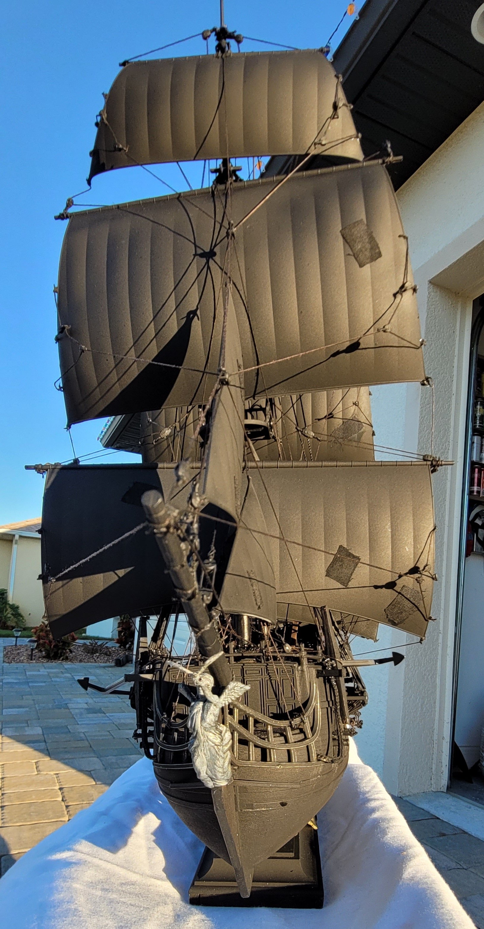
Fantastic build sir! Your thread offers a plethora of information and advice which is greatly appreciated. I just ordered the Zvezda Pearl kit and cannot wait to dive into this build. My aspirations are to add a few flickering LED's to the lower decks, Capt's quarters, & the three aft lanterns. May I ask what is the thickness of the planking you used on your deck? Also, it appears Gator Glue isn't readily available in the States and I wonder if Gorilla Glue is a compatible substitute? I think it would be but checking with the expert(s) on this one. Again, well done sir !