Electlen
-
Posts
17 -
Joined
-
Last visited
-
 GrandpaPhil reacted to a post in a topic:
George W Washburn by Electlen – Dumas – 1:48
GrandpaPhil reacted to a post in a topic:
George W Washburn by Electlen – Dumas – 1:48
-
GrandpaPhil reacted to a post in a topic:
George W Washburn by Electlen – Dumas – 1:48
-
gjdale reacted to a post in a topic:
George W Washburn by Electlen – Dumas – 1:48
-
yvesvidal reacted to a post in a topic:
George W Washburn by Electlen – Dumas – 1:48
-
yvesvidal reacted to a post in a topic:
George W Washburn by Electlen – Dumas – 1:48
-
Frodo reacted to a post in a topic:
George W Washburn by Electlen – Dumas – 1:48
-
Paul Le Wol reacted to a post in a topic:
George W Washburn by Electlen – Dumas – 1:48
-
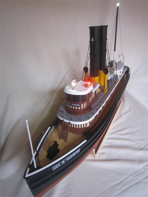
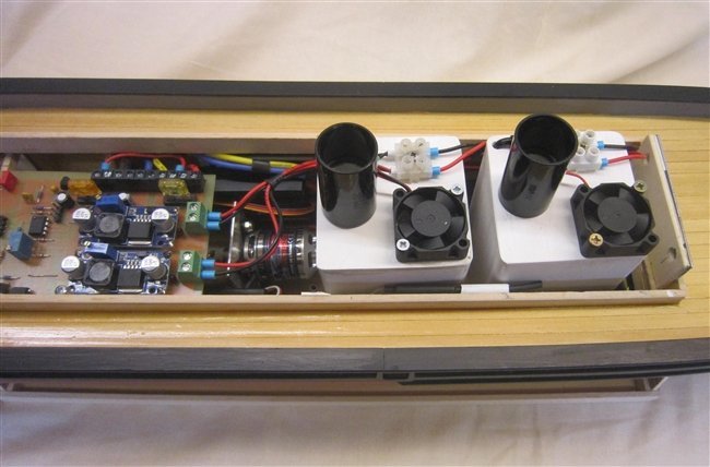
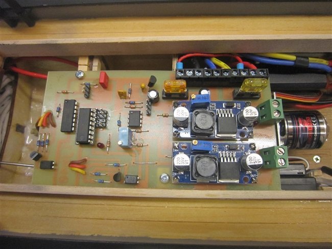
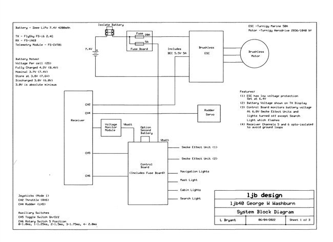
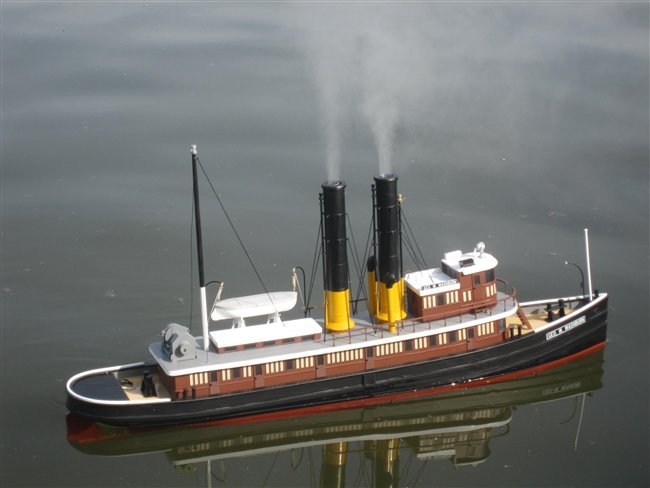
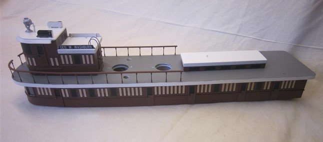
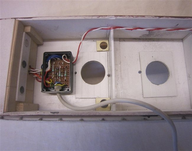
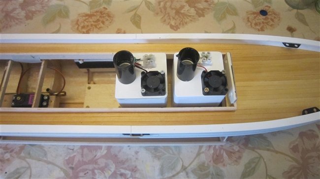
 The cabin has been completed along with the few remaining bits on the hull, so the boat is now finished. No real problems, just followed the instructions. All the lights working, indoors they look too bright but out on the water it will be fine. The lights are switched on by a control on the transmitter, in sequence Navigation Lights, + Mast Light, + Cabin Lights, +Search Light. The FlySky Receiver FS-1A6B is fitted with a telemetry module FS-CVT01 which monitors the battery voltage and sends it back to the Transmitter display, useful to watch how the battery is discharging. This picture shows the two Smoke Effect Units, the smoke stacks were mounted through the cabin roof to make with the pipes, The mist (to simulate smoke) is generated by an ultrasonic module which requires 24V at 0.5A, this voltage is created by a DC-DC Booster circuit from the 7.4V battery. The load on the battery is quite high, calculated as follows: 24V x 0.5A = 12W, two units = 24W Booster circuit efficiency is quoted as 95% so input power = 24/0.95 = 25.3W Battery current = 25.3/7.4 = 3.4A To control the functions on the boat I designed and built an electronic circuit which made use of the two auxiliary channels on the transmitter, Channels 5 and 6. Channel 5 is a two position toggle switch which is used to switch the Smoke Effect Units on/off. Channel 6 is a 5 position rotary switch to control the lights. The DC-DC Booster modules can be seen on the right hand side of the board. Channel 5 is read by a Picaxe 08M2 micro-controller chip which is also measuring the battery voltage. At 6.8V the chip will switch off the Smoke Effect Units. Channel 6 is read by a Picaxe 14M2 chip which switches the lights on. I am quite happy to share the details of the board, send me an email. In the water the boat, with no extra weight, kept rolling on its side. Not a good start but probably not unexpected. I added about 2.5Kgs of lead weight to the bow and stern areas which made a big improvement. However it needed to be sailed very gently otherwise it easily leaned over. Putting full throttle on caused it to roll, when I get time I will fit a smaller propeller which should reduce this effect. Full rudder at a reasonable speed caused it to roll sufficiently to flood the decks. With no escape holes the water stays on the deck which makes the leaning worse. Having adjusted to its characteristics I did enjoy sailing it for about 30 minutes. I may consider fitting an extension to the keel to see if it improved the stability. Finally the Smoke Effect Units worked really well. I was never really sure if the effort would be worth it but pleased with the result. Of course the two containers of water could be contributing to the instability problems. The final photo is the boat on the lake. I can see that it may require a bit more weight to lower the bow, consider that to be work in progress. End of log.
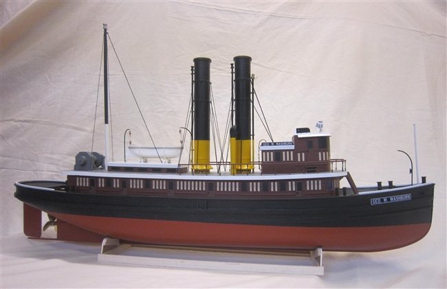
-
GrandpaPhil reacted to a post in a topic:
George W Washburn by Electlen – Dumas – 1:48
-
GrandpaPhil reacted to a post in a topic:
George W Washburn by Electlen – Dumas – 1:48
-
GrandpaPhil reacted to a post in a topic:
George W Washburn by Electlen – Dumas – 1:48
-
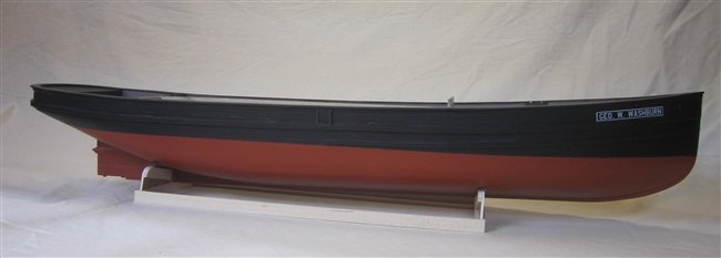
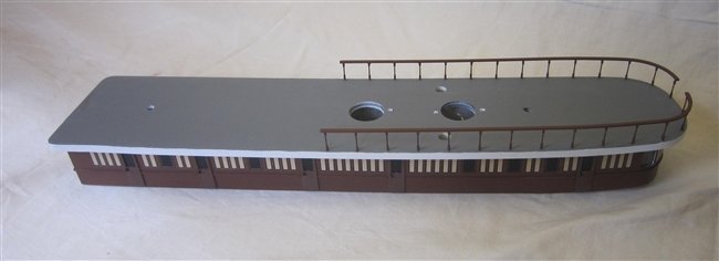
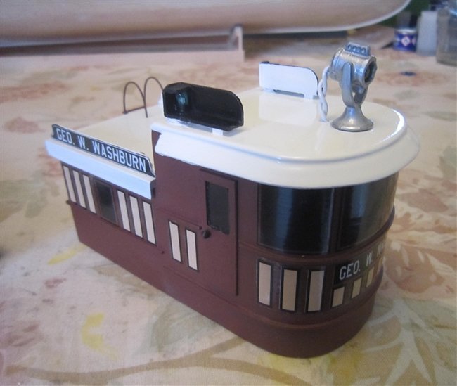
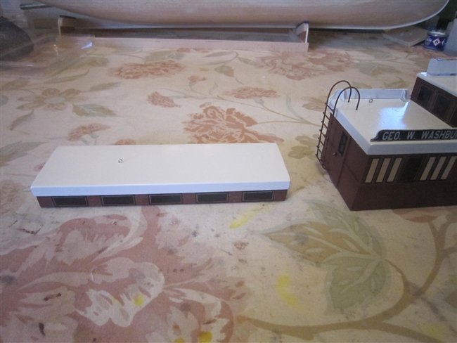
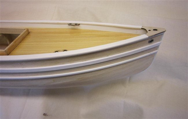
The hull has now been painted, just followed the instructions to establish the waterline. The lower part was painted using Simoniz Acrylic Red Oxide spray as I could not source the original Krylon Ruddy Brown. Making good progress with the superstructure, I decided to tackle the tricky railings. Found it easier to glue the pins into the cabin before attempting to fit the hand rails. This was so that the pins did not move when pressing down with the rails. Next the Wheel House and the Skylight were glued in place. I suddenly realised at this point that I had work to do on the under side of the cabin so now had to rest it upside down. The work required was to wire up the various lights which had been fitted, these were: front cabin windows, search light, navigation lights and the light on top of the mast. For the search light I drilled out the supplied cast metal fitting and fitted a 5mm white led. This can be seen in one of the previous photos. The navigation lights are red and green leds fitted instead of the supplied cast fittings. For the mast light I decided it was not going to be possible to drill out enough of the cast metal fitting for it to look realistic so I searched for an alternative. Eventually found that the Aero-Naut 8mm Illuminated Mast Light 5664/21 was almost an exact copy of the supplied fitting. The two wires heading in the direction of the stern in the photo below are soldered to the two eye pins which form the bottom of the rigging up to the top of the mast. Enamelled copper wire painted black will be used for the rigging to the top thus connecting with the light fitting, that at this stage is the theory. The series resistors for the leds can be seen in the photo. The three magnets (also fitted at the other end) which can be seen have been fitted to help retain the superstructure to the hull in the event that the whole boat is swamped by water when being sailed. Metal plates have been fitted to the superstructure which correspond with the magnets. Having completed the wiring I continued with the top side of the cabin.
-
No, it was considered but I decided it was not necessary. The inside had clear epoxy resin applied with fibreglass tissue, this strengthened the balsa wood. For the outside I applied a number of coats of Deluxe Materials Sand 'N' Seal wood grain sealer. A bit of a risk as not the 'hard shell' finish that resin would have provided, however it avoided the sanding required to get the finish on the resin. If it suffers collision damage when being sailed it is easy enough to repair. I shall be painting the hull in the near future so it will be interesting to see what sort of finish I get on the sealer.
-
6 The Superstructure The very cold weather has slowed work down as I have been limited as to what could be done in the Garage, although I have managed to complete some jobs. I decided to have a go at making two smoke effect units to create the illusion of smoke being emitted from the smoke stacks. They use plain water which is turned into a mist by an unltrasonic unit operating from 24V DC, this is then pressurised to travel up the stack by a fan. The results were quite encouraging indoors, the real test will be outdoors when there is a bit of wind. Needed to complete this before starting the cabin as it will require the smoke stacks to be fitted through holes in the roof. Of course it might turn out to be a complete waste of time and effort if the weight of the units upsets the balance of the boat or even make it unstable. The photo shows the two units in the hull. The Wheel House and the Sky Light have been completed. The navigation lights have been fitted with working red and green leds and the searchlight has been drilled out and a high brightness white led fitted to create a working light as shown in the photos.
-
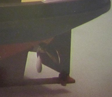
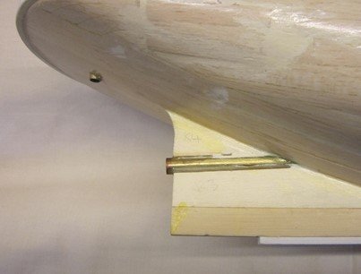
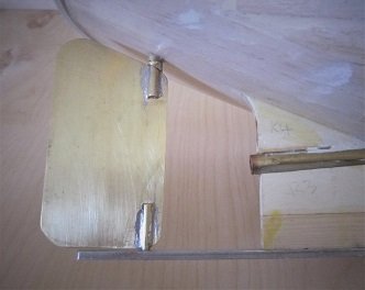
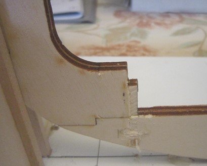
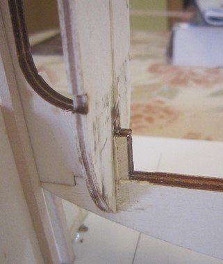
5. The Rudder It is apparent that Dumas changed their mind when designing the kit. The illustration on the front of the box clearly shows a support bar attached to the skeg to the bottom edge of the rudder. The instructions when fitting the plastic strip to the keel was to stop 1.5inches from the end of the skeg, thus permitting the fitment of a support bar. However, the support bar was not provided in the kit and the instructions for the assembly of the rudder was limited to the soldering of the shaft up through the Hull. Given the large size of the rudder and the fact that it was made with quite thin brass sheet, much thinner than that normally used for a rudder, I decided that fitting a bottom support would provide some protection against it being bent if the boat was grounded. The rudder now looks like this: That completes the work on the hull for the time being, the construction of the superstructure is next.
-
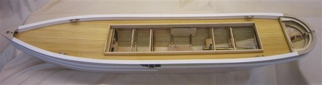
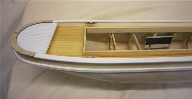
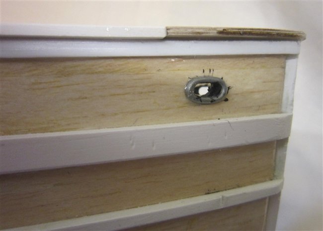
The deck has now been fitted to the hull. I glued the planks to the sub deck and completed the assembly by sanding and applying a number of coats of clear varnish. The deck was then trimmed so that is was a snug fit inside the hull and glued in place with 90 minute epoxy. Thus I had time to apply the glue to all the surfaces before it started to set. The deck was weighted to keep it against the frames and allowed to set overnight. Rather than just glue the Hawser Pipes to the surface of the hull I cut slots through the hull to make it more realistic.
-
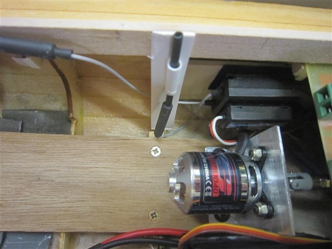
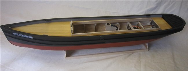
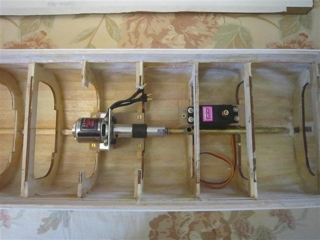
4. Hull completion I have now made progress with fitting the various plastic strips to the hull. Before starting the work on the deck I decided to make and fit the mountings for the motor and the rudder servo. Two of the frames were cut back to improve the access, one of these was added as an extra to improve the rigidity of the planking.
-
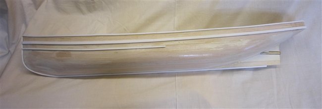
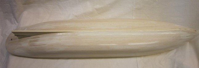
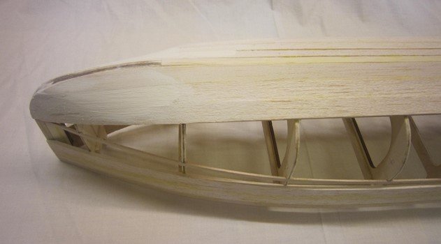
I have now applied clear epoxy resin with a single layer of fibreglass tissue to the inside of the hull, this has strengthened it enabling some serious sanding to take place to the outside. The outside is now nearing completion, it has been filled and sanded with numerous coats of Deluxe Materials SAND'n'SEAL.
-
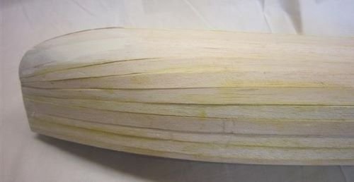
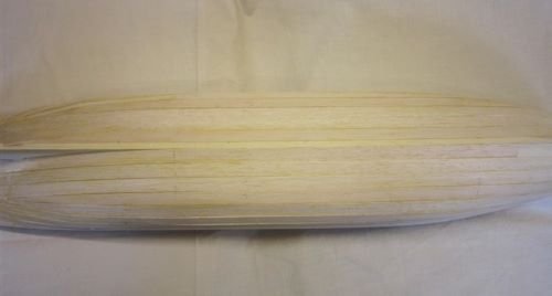
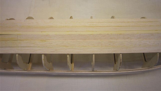
The planking is now complete. The photos show the raw planking with no sanding or filling apart from the patch at the bow. The next step is to seal the inside of the hull with resin.
-
I have made further progress with the planking. The mid-section and stern are looking good. At the bow one or two of the balsa strips cracked at the frame where it was being stressed. The instructions say to chamfer the edge of the frame which I did. I thought the balsa would be pliable enough to avoid this but obviously not. I tried soaking the strip in hot water but this had little effect, it still cracked. The result was that the strips that had cracked went straight across instead of having a curve. Having experimented with some filler, which disguised the problem, I decided to press ahead without trying to soften the strip. This can be seen in the photo.
-
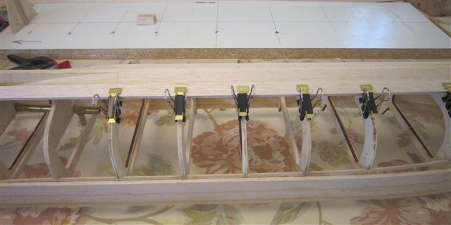
Planking continued. Made a start with the planking. I tried using CA glue on the frame edges but where the strip was under tension it broke away leaving a sliver of balsa on the glue. So I am using wood glue, takes longer and does require some inventive clamping but good progress is being made. The next two photos show the use of the clips. The black clips are the Amati Clamp Set (pack of twelve).

-
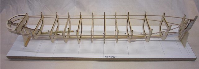
I am now back on the build. I have given careful thought to the comments made by Tom and Roger with the conclusion that if I pressed on without making changes then I risk being disappointed with the end result. So, to be sympathetic with the frame structure, I made three new frames and glued these in the three large gaps. For the planking I shall use the balsa wood supplied because (a) I have it and (b) it is pliable enough not to need any pre-treatment. The hull now looks like this:
-
Thank you both for your advice, I shall take note of it. The problem area will be the three gaps between frames 4, 5, 6, and 7 which are all 4 1/8". The others are 3" or less. It is single plank using balsa wood strips 1/8 x 1/4" and 1/8 x 1/2". The instructions say to fibreglass both inside and out with the final finish on the outside being paint. Len
-
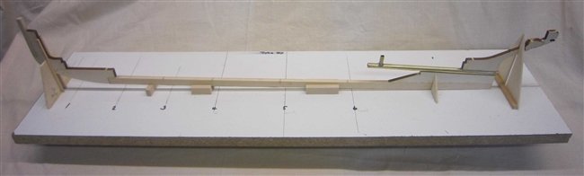
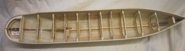
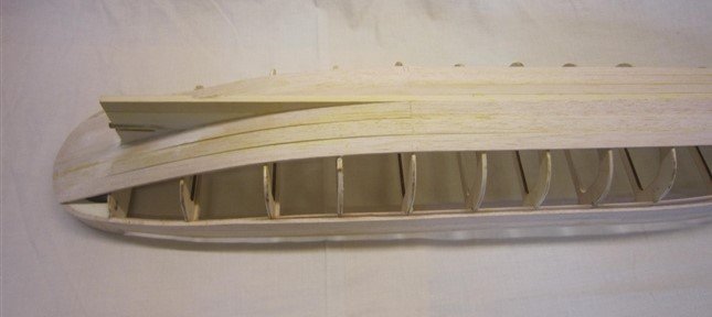
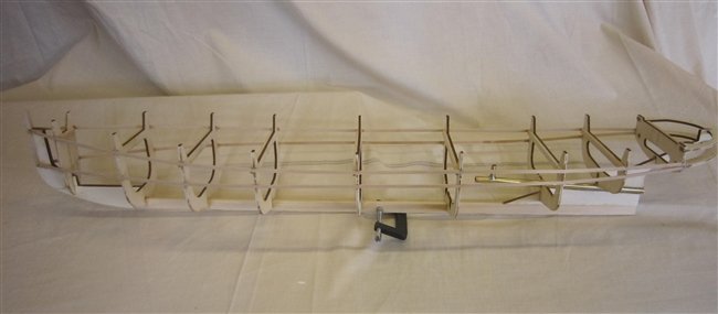
2. The Frames For each frame I marked its correct position on the baseboard with a line that was perpendicular to the keel. Glued each frame to the keel in turn using 2 part epoxy which gave me time to position it correctly. Used 2 metal squares on the baseboard to check it was vertical. I started with Frames 5, 6, and 7 as the tops of these were all equal, corresponding to the flat part of the deck. Either side of these the deck rises. When I started to position the sheer strips (1/16 x 1/8”) along the edges of the frames it was clear that Frame 1 was not in the correct position, it was too low. There was no drawing that showed clearly the position of Frame 1. Also, the front of the keel K1 had a notch in it which was not shown in the drawings. I had assumed, incorrectly, that the notch was to locate Frame 1. This was why the frame was incorrect. I managed to break the glue and remove the frame with only minor damage to the keel, it lost a bit of its outer plywood. Frame 1 was then glued back as shown in the photo. K1 with notch F1 The structure was completed with no further problems, I was pleased with the end result. It was very uniform in shape with no distortion. 3. The Planking I am busy over the next few weeks so the planking is on hold.
-
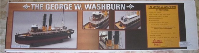
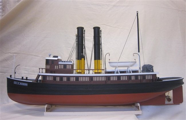
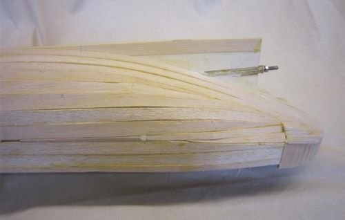
Greetings all, as a winter project I decided I would like to build the George W Washburn. For a number of reasons: · I liked the look of it · Wooden construction with plank-on-frame hull · Good size and within budget · Build logs on MSW to refer to On opening the box, I was quite impressed with the contents of the kit. The Instruction Booklet is 56 pages long and there is a separate pack of drawings to go with it. There is basswood for the structure, balsa for the planking and some plastic parts. The quality of the wood seems to be good. It is my first plank-on-frame boat since I scratch built a Police Launch in the 1980’s so class myself as a beginner. There is a comment in one of the Forums that ‘single’ p-o-f is for the more experienced builder as there is no second layer to cover up the faults of the first. No pressure then, however the instructions for the Dumas Kit were more encouraging. It says the model was designed to make its building as fool proof as possible. We shall see! The length of the model is a bit of a puzzle. From the keel parts I estimate the length of the finished model to be 800mm (31.5”), this agrees with the 1:1 scale plan drawing supplied. But the box lid gives it as 30” (762mm). On searching for the length of the actual tug boat I could only find one source which gave it as 140’. Divide this by 48 and you get 35”. The existing Build Logs were published by lb0190 in 2013 and MarkBseau in 2014. I shall try to spot if Dumas have made any changes to the kit since then. As per the instructions I made the stand as the first task. Although not needed until much later it was a chance to try out the adhesives. I am not much of a fan of CA glue, I shall mostly be using a waterproof Aliphatic Wood Glue and 2 Part Epoxy (Araldite). For some weird reason I used the wrong strip wood for the stand, 1/8 x 1/4 instead of the correct 1/4 x 1/2. Not a good start. So, I made two new ends and built it again. 1. The Keel No problems assembling the keel except that the bass wood strip which formed the basis of the keel was oversize, it was too thick by just over 1/32” thus preventing the frames from being fitted. Rather than plane down the thickness to suit the frames I purchased a new piece of strip 6 x 15mm and planed that down to 6 x 12.7mm. For the prop shaft, the Material List gives the tube as 5/16” diameter and length 5-3/8” and the shaft as length 8-13/16”. This means that there is 3-1/2” of unsupported shaft, probably not a problem but not a technique that I would usually follow. In the UK most suppliers stock complete assemblies with the shaft having about 15mm threaded protrusion at each end of the tube. The tube would be fitted with bushes at each end to support the shaft and possibly come with the option of an oiler tube. I usually fit an oiler tube with oil being used instead of grease. Though it is important not to have oil in the prop shaft when commencing sailing as this can result in a slick on top of the water. So, having finished sailing I would prop up the bow and ‘inject’ oil using a lever action oil can. Any water in the prop shaft gets ejected, I then leave the boat propped up for a few days until no more oil is seen around the end of the shaft. Thus the tube is clean on the inside and the bushes lubricated. I purchased an 8” assembly with M4 threads at each end. For the oiler I cut a piece of brass tube and soft soldered it to the prop tube with a 3mm hole through to the shaft. This can be seen in the photo. 2. The Frames To follow.