ted99
-
Posts
235 -
Joined
-
Last visited
Content Type
Profiles
Forums
Gallery
Events
Everything posted by ted99
-
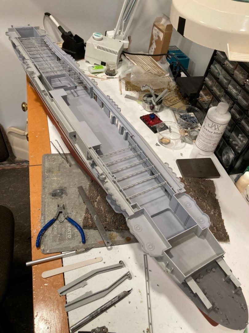
catapult equipment compartment--one each side. bashed up from roller doors I did not use. The Trumpeter kit made no sense with the bare platforms. Both Trumpeter and MK 1 put a railing around each platform, but no way to access. Better, now.
- 154 replies
-
- 4
-

-
- Enterprise
- Trumpeter
- (and 1 more)
-
Aha. Thanks for both pieces of info. I'll be able to repurpose some of those roller doors for the Hanger deck that I didn't install.
- 154 replies
-
- 2
-
-
- Enterprise
- Trumpeter
- (and 1 more)
-
Apologies. I hadn't loaded the pictures from my iphone to the computer, before. Done now.


- 154 replies
-
- 5
-
-

-
- Enterprise
- Trumpeter
- (and 1 more)
-
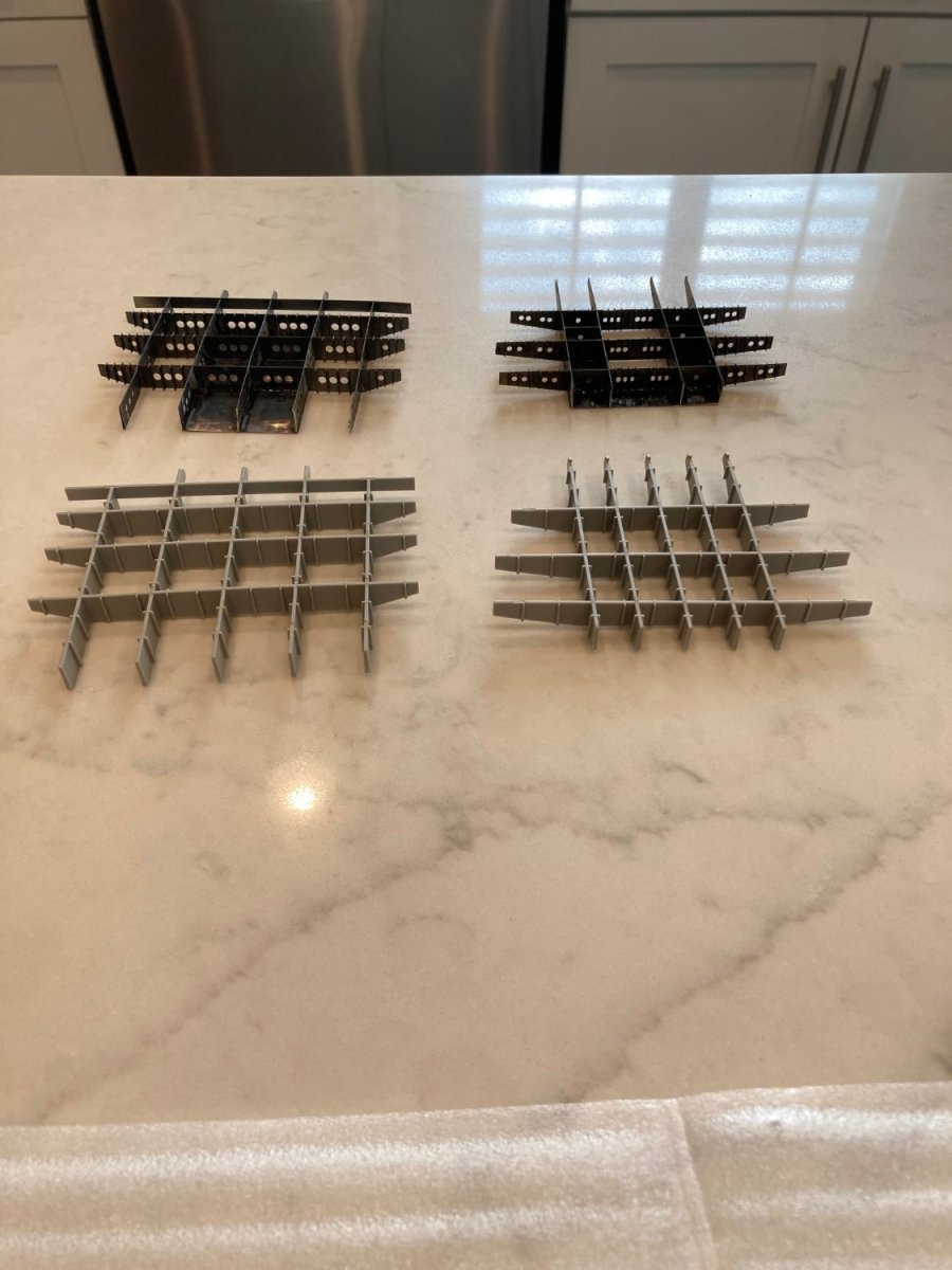
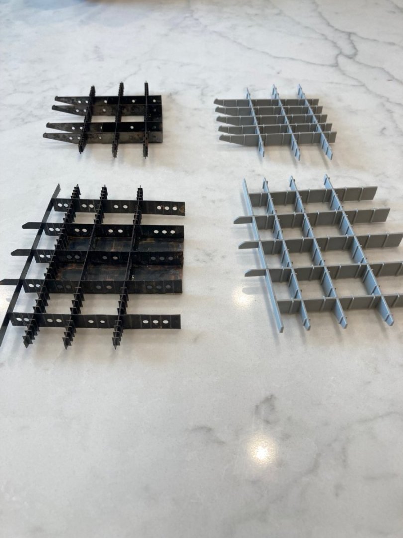
As promised, pictures of the Flight deck lattice supports at bow and stern. Pictures juxtaposed with the Trumpeter kit parts. You can see the horseshoe-shaped compartment inside the bow lattice which contained the catapult machinery. I take back what I said about Trumpeter not including the bow catapult rails in the kit. I just removed the two pieces of the Flight deck from their plastic protectors and padding was wrapped around the bow, hiding the launch rails molded-in detail. Box art did not show this. As you might be able to see from the pictures, the Flemish gray coating turns a dark brown/gray with age, plus it peels off if tension is placed on a CA joint between two brass pieces, exposing the brass beneath. Consequence: a weak joint for larger pieces. As a result, I do not think that use of the Jax Flemish gray is a good idea for coloring the PE brass, in lieu of gray paint. A question for those with far better research materials: I've shown a picture of the bottom of the aft end of the Flight deck illustrating the two cutouts Trumpeter calls for at each side of the curved part of the Flight deck. One cannot see these cutouts on the top of the Flight deck leading me to the idea that at some time, those cutouts were not there. Can anyone provide any info on this?
- 154 replies
-
- 2
-
-
- Enterprise
- Trumpeter
- (and 1 more)
-
Yes, read about Enterprise's escort duties. As I said, "JUST FOR FUN".
- 154 replies
-
- 1
-
-
- Enterprise
- Trumpeter
- (and 1 more)
-
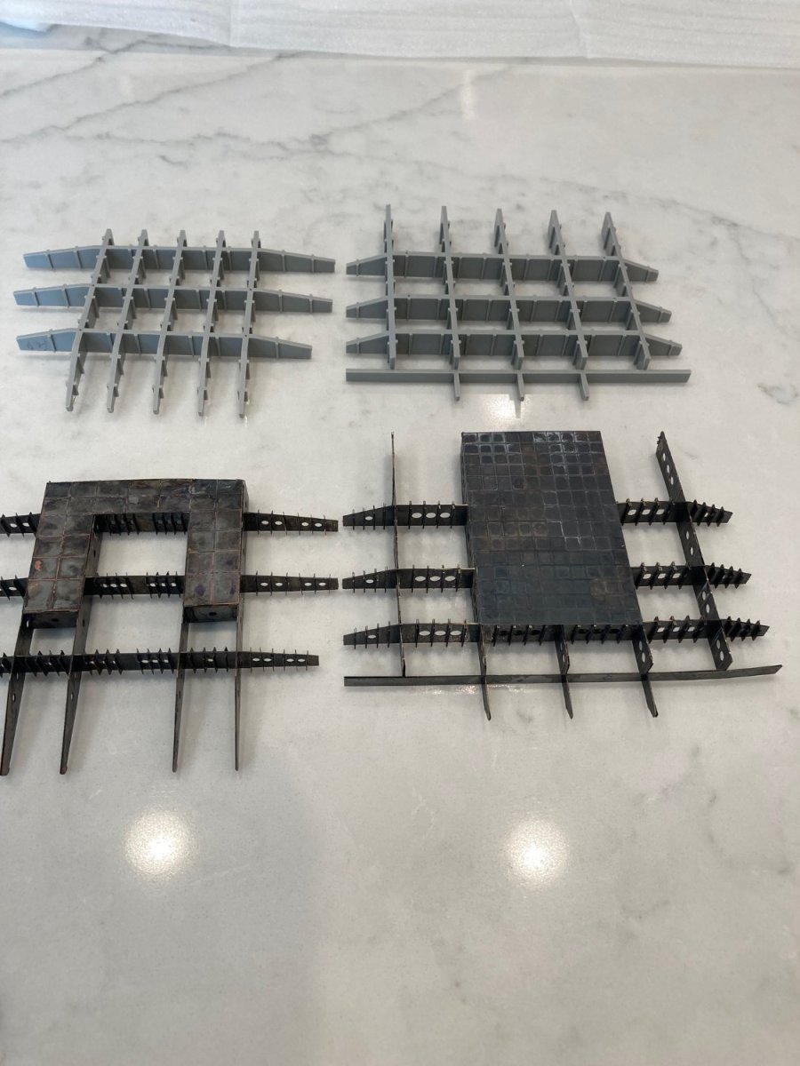
Got it. The drawings are extremely helpful. The MK-1 detail set HAS the enclosure. It's part of the bow flight deck lattice support. I'm assembling that now and will show pictures later. The Trumpeter kit does not have any machinery space for a catapult on the hanger deck, a wide side door, rails, or a machinery space at the bow. Nor, is there any provision for the rails in the flight deck. BUT, the MK 1 detail set for the wooden deck DOES have the bow rails. So, with both the catapult machinery space and the bow rails (which the Trumpeter kit is missing), the MK 1 detail set is very accurate to the original. The kit includes four each of the F4F-4, TBD-1, and SBD-3. I purchased a set of 4 of the Trumpeter B-25's from the Dolittle raid. I'm going to put one on the flight deck just for fun. I'll put the F4F's and one of the SBD's on the flight deck simulating readiness for CAP and the others on the Hanger deck. My version of the MK 1 detail set does not have the extra details for the aircraft that added wing-folding capability.
- 154 replies
-
- 2
-
-
- Enterprise
- Trumpeter
- (and 1 more)
-
Well, isn't that interesting!!! No hanger deck doors wide enough for a plane in the Trumpeter kit and no place at the bow for a machinery space--just that compartment immediately aft of the bulkhead behind the anchor capstans. With a Hanger deck catapult, is that large structure on the hanger deck under the Island the place where the launch equipment could have been located.
- 154 replies
-
- 2
-
-
- Enterprise
- Trumpeter
- (and 1 more)
-
^^^ I'm attaching a pertinent page of the Trumpeter assembly manual that shows a compartment just aft of the anchor capstans that "could" be the catapult machinery compartment. In the Trumpeter kit, those four pillars at the bow are supports for the latticework flight deck supports. I'll be showing a picture of them soon. Well, live and learn. I was aware of the Brit development of steam catapults post WW II, but not that any of any type were on the WW II carriers. In any event, the Trumpeter kit flight deck does not have any provision of the "rails" that would have been embedded in a catapult mechanism. So, I'm presuming that the model is for the period after the catapults were removed. The Wikipedia "history" of CV-6, that did mention the addition of belt blisters during a yard availability did not have any mention of catapults. Thank you very much for those Yard drawings of the armor belt. Looks like it would have been an easy add at an early stage. No compound curves--just build up styrene sheet strips until .5mm thickness was reached. Had I known, I would have done this. Ah well, lots to learn in this hobby and the importance of research. I wish someone had done a build log of CV-6 before, that I could have learned from. SCAN_20230705_101758434.pdf
- 154 replies
-
- 2
-
-
- Enterprise
- Trumpeter
- (and 1 more)
-
When looking up the history of CV-6, I saw a reference to "blister armor" being added at a yard-availability during the Pacific campaigns, but could find no pictures of it. The reference to "blister" was problematic, too, as I had never seen anything remotely looking like the other pictures I found regarding blister armor. From ddp's question, I surmise that what was added was a 4" thick belt of armor attached to the exterior of the hull, not a blister. But, lacking any reference materials, I don't know where this belt was located. If it didn't extend into the areas of the bow and stern curvature, or too far down, it could have been relatively easy to add with a plastic strip. I presume it was for torpedo protection, but don't know how much it extended above and below the waterline. Wouldn't have been very useful with proximity-fused torpedo's detonating beneath the hull, anyway. If Buships had been more concerned with making our MK-19 torpedo detonators work, in the early days, it would have been much more useful than this "gilding the lilly" stuff. This armor belt is useful note for future builders wanting to model a particular period for CV-6.
- 154 replies
-
- 2
-
-
- Enterprise
- Trumpeter
- (and 1 more)
-
If the catapult machinery enclosure you are referring to is the large structure on the hanger deck immediately beneath the island, it's there. Earlier pictures of the flight deck show it. One of the first things attached, as it's the anchor for the starboard sides of the hanger deck. Since I did not spring for any reference books on CV-6 (turned out to be overkill for Yamato), if it ain't labeled on the Trumpeter "instructions", I don't have it. I wondered what that enclosure was for and made a logic leap that it's the catapult machinery enclosure you are describing. However, it's news to me that there were catapults on WW II-era carriers.
- 154 replies
-
- 2
-
-
- Enterprise
- Trumpeter
- (and 1 more)
-
It's there, photo angle just doesn't show it. Trumpeter didn't include the armor belt in their casting, so I let it slide. At the outset, I decided I would build the kit "as is", except for detail pieces. The simulated hull plating was an easy exception as it helps a lot, for little effort.
- 154 replies
-
- 2
-
-
- Enterprise
- Trumpeter
- (and 1 more)
-
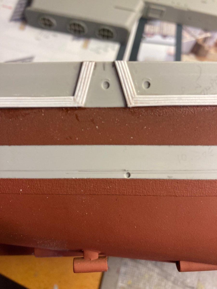
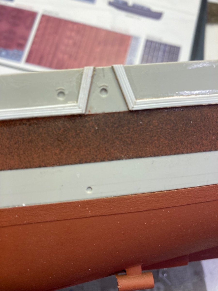
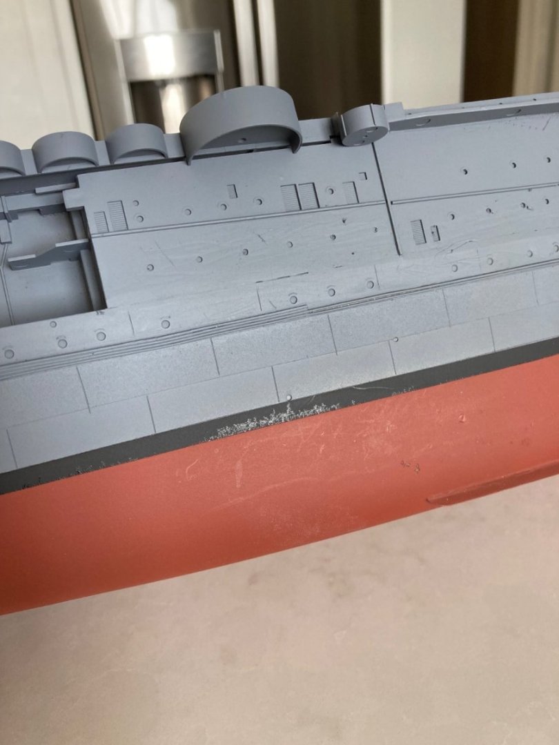
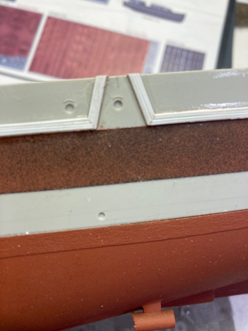
Had a break in the wind this morning and was able to do the hull painting. Two close-ups of the panel detail. The horizontal lines were from the alternate 10mm-wide masking tape with 4 coats of Rust-oleum automotive primer on unmasked 10mm-wide strips. I'm very pleased with the panel definition. Vertical lines done with a fresh #11 exacto knife and the horizontal lines an artifact of the alternate lines of no-primer and 4 coats of primer. Just enough definition. Note that I did not do any simulated panels in the underwater anti-fouling paint part of the hull. Seemed like overkill and I'm happy with it missing. So, this has proved to be a very satisfactory way to simulate panel lines. No research into where the actual panels were--just what looked like "good enough", without being obsessive about the prototype.
- 154 replies
-
- 9
-
-

-
- Enterprise
- Trumpeter
- (and 1 more)
-
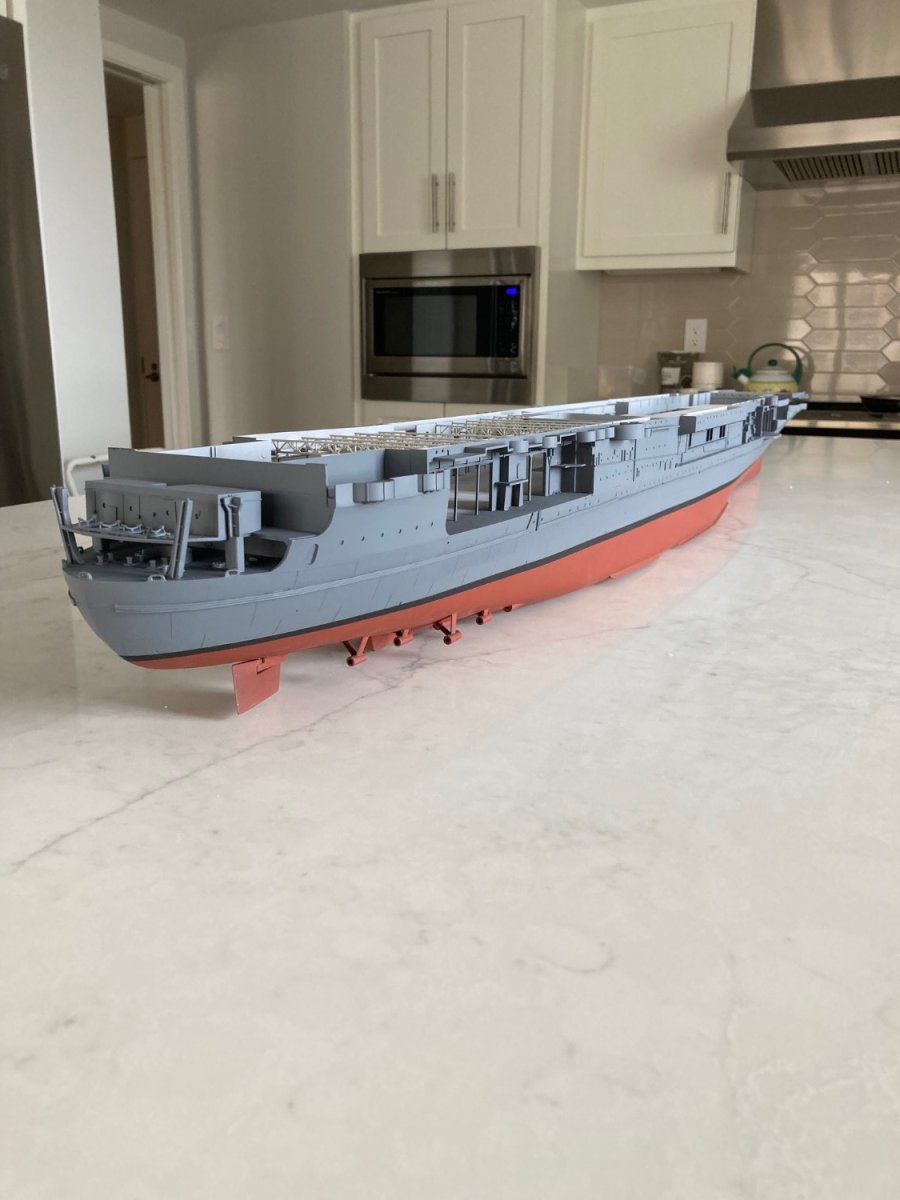
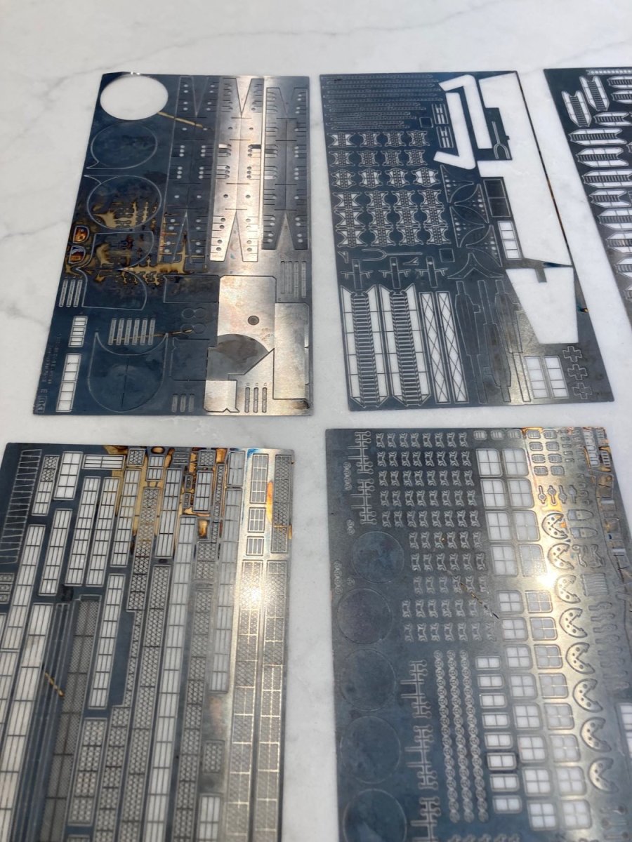
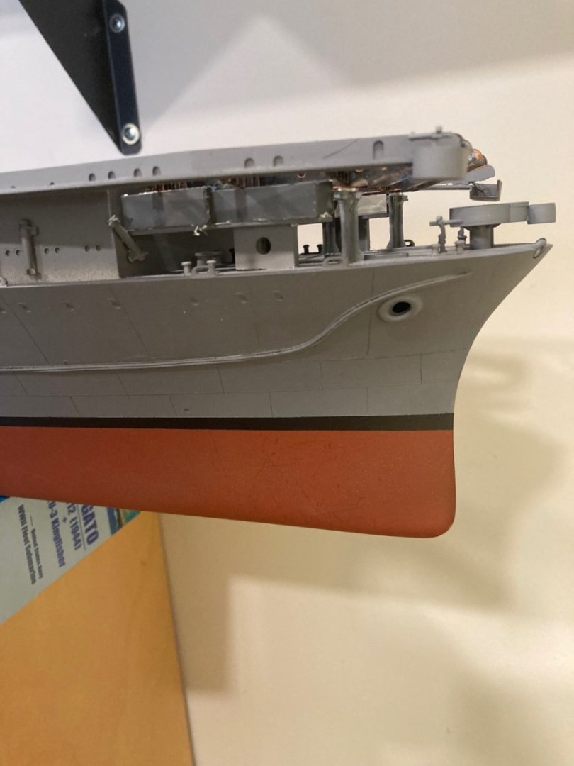
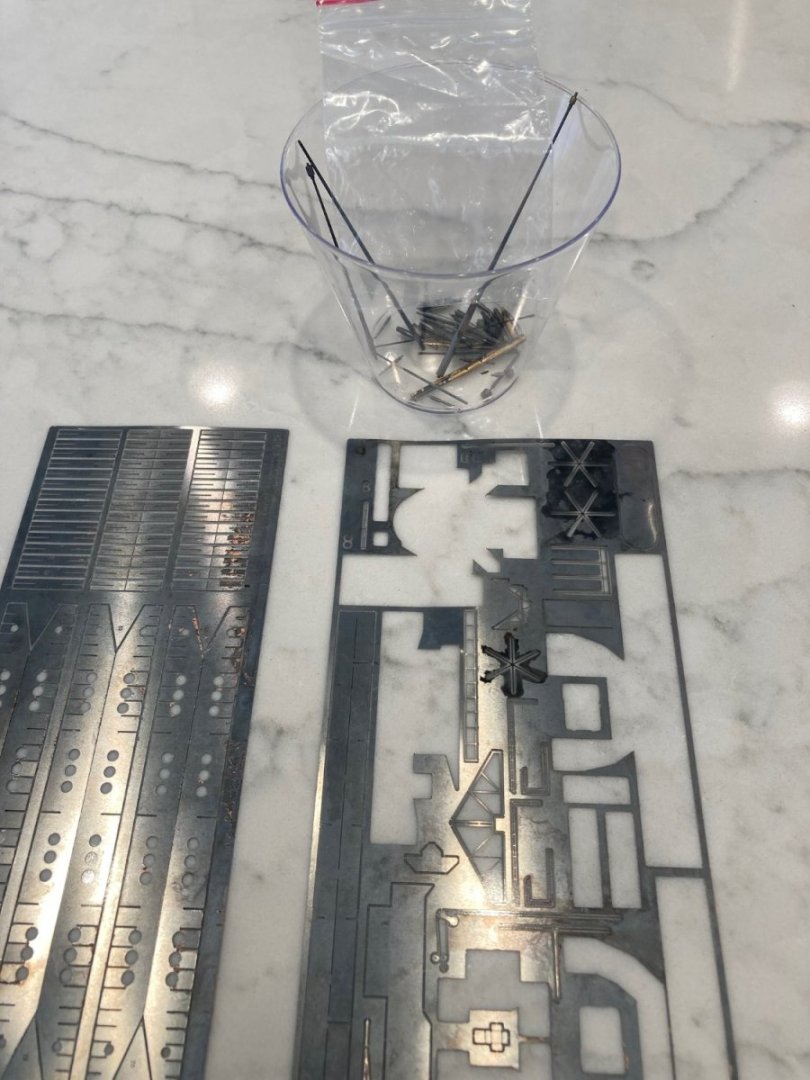
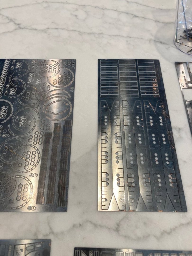
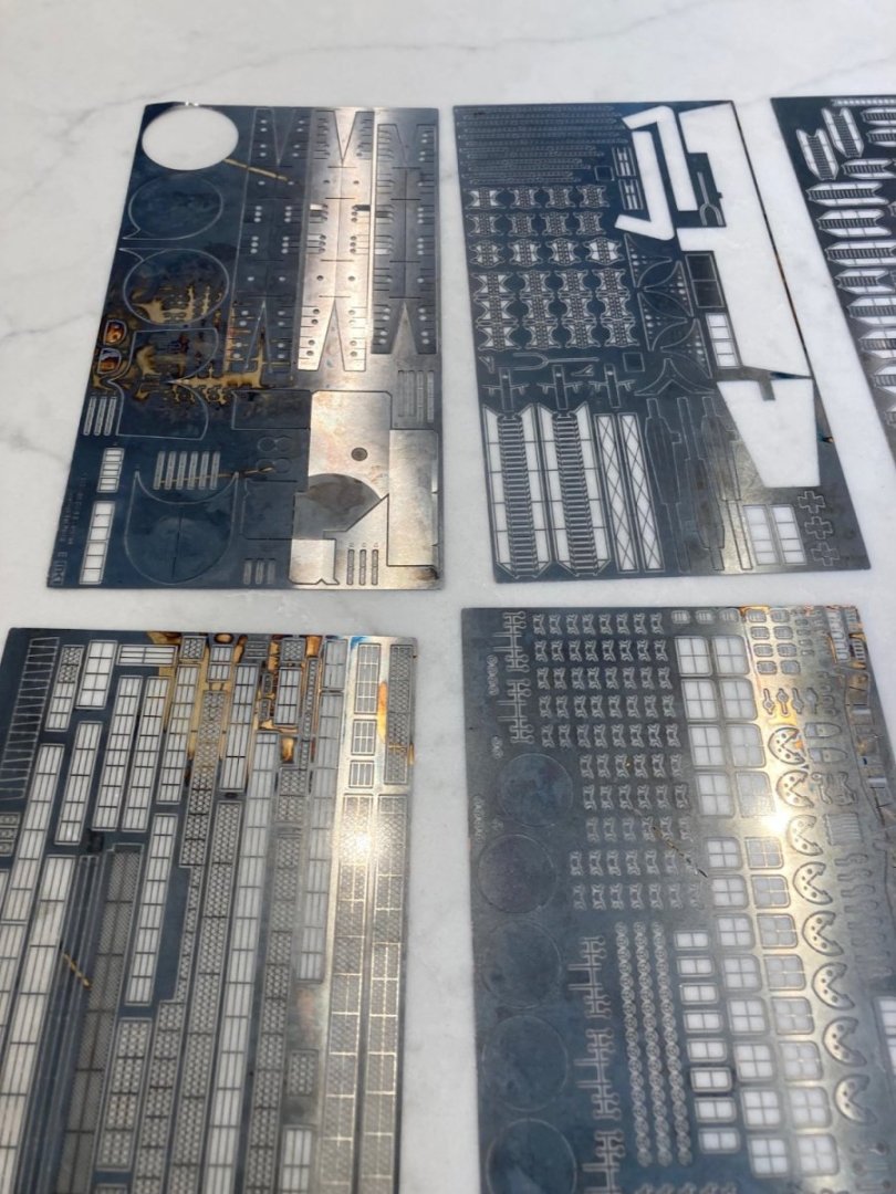
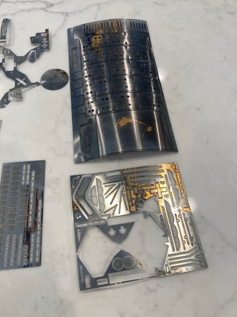
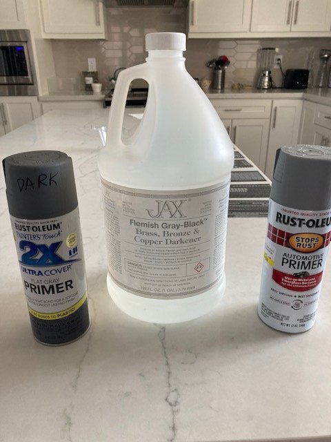
While waiting for the wind to die down, I did a run of Jax Flemish gray on my MK 1 PE brass. I like it. It's a bluish gray and will blend well with the "Navy Blue--Rust-oleum 2X" hull color. The Buships instructions for Measure 21 say to paint over the standard Navy gray on the vertical surfaces but not to worry about coating all the surfaces of smaller structures. I read that as "Don't sweat the small stuff", so this Flemish gray should be a good match to the hull paint for the PE details I will be adding. There will be a little PE excess at the attachment points (less and less as I get better), but a final coat of Matte clear over all surfaces, as I did for Bismarck, should render that invisible( fingers crossed). All this in aid of reducing paint-masking of PE details. Roger--I'll have a look for the Humbrol blue stain, but it will have a hard time competing with an $8, 1/2 pt can of Min-wax. It's oil-based, so I don't expect any curling of the thin wood veneer deck from MK 1. I'll do a test on a left-over piece of Yamato decking, first. I'll have to stain the deck pieces before attachment to the flight deck, though. There will be inevitable excess PVA glue at the edges of the many, many deck pieces, which would not absorb the semi-transparent stain. I have to use stain as I want to preserve as much of the printed-on details as possible. The MK 1 detail set also has PE stainless steel for the separators/tie downs on the flight deck. Way too silver and bright. I gave the Jax chemicals a try at changing the color of the SS to blue or black. Went thru Flemish gray, gun blue, steel black, pewter black and aluminum black with no results. Unless someone knows of a blackening agent that will work on SS, I'm going to have to do a very light spray of the SS PE sheets with paint, before assembly. As to the process I used for the Flemish gray: First step was to do a wash of the PE sheets with dishwashing soap and rinse. Then an overnight soak in White Vinegar. I used a pyrex rectangular dish with a flat bottom and separated each PE sheet with a couple of pieces of left-over sprue. That allowed me to do all of the PE set in one go. After another rinse, I repeated this with the Jax Flemish gray. The graying happens quite quickly, but I left the pieces in the solution for about an hour just to see what else happened--nothing. I had bought a gallon of the Jax Flemish gray, after seeing how fast the 2 oz bottle I bought on e-bay got used up when I gave this a try on Yamato. In the pictures of the PE sheets you can see a few "holidays" where the chemical process had not taken. By process of elimination, I determined this was due to sheets of PE brass sticking together in the chemical bath. A subsequent rub with a Q-tip resolved most of those problems. However, there were a few edges of PE pieces that turned copper-colored. I am guessing that this was due to imperfections in the brass sheet that I will have to deal with if it's visible after assembly with a dab of paint. The next time I do this (on Missouri), I'll dip each sheet individually for about a minute each and see how that works out. The coating seems a lot like anodizing. You can't rub it off, but can scratch through it. Looking forward to seeing how this ends up on the completed model. Picture shows the 2-cans of primer I used and a gallon jug of the Jax Flemish Gray. This go of coloring used about a quart of the chemical, which I saved to see if it's still reactive if I need to do some more parts. Again, research on Measure 21 says that the Hanger deck floors were standard Navy gray, but the walls were White. I came on this after I had masked the hanger deck and decided to just paint the whole interior of the Hanger deck Navy gray. This is forewarning for future builders. If I were to do it again, I'd follow this process: Before gluing in the ceiling girders over the Hanger deck, paint the walls white. Then, mask the walls off and paint the floor Navy gray--this is a lot easier without the girders.. If you are going to paint the girders (Navy gray), do it before assembly. I didn't paint them because they will be impossible to see through the side roller doors once the Flight deck is attached. Finally, assemble the girders with CA glue as all the plastic is covered with paint and plastic solvent won't work. A further note for future builders: As I mentioned earlier, I omitted the roller doors to allow sight lines through them to the interior of the Hanger deck, where I will have a few of the aircraft included in the Trumpeter kit. I did place the roller doors in any place where there was nothing to see through them, but I forgot the ones directly beneath the Island. There is a solid structure on the part of the Hanger deck directly beneath the island and there are three roller doors in the Hanger deck starboard bulkhead where I neglected to install the roller doors. Too late now--they are just black holes now, unless light is shining directly on them.

- 154 replies
-
- 9
-
-
- Enterprise
- Trumpeter
- (and 1 more)
-
I'm waiting for the wind to die down enough to use my balcony "paint booth" to spray the final hull color. Once that's done, I'll be able to assess the painted hull panels. I've painted the interior of the hanger deck and masked all of this area in preparation for hull painting. Enclosed is a picture of the painted interior. I have attached all the PE brass pieces to the hull that I am wanting to be painted hull color (mostly hatches). The rest of the PE brass is going to be chemically treated for a gray color before assembly and placement on the hull. I'll have more details on this later. In painting the hanger deck, I initially used Rust-oleum 2X gray primer, but after application, it was closer to a dark blue than gray. After seeing this, I reappraised my thoughts on paint color. The 2X primer looked very much like the "Measure 21" camo scheme, where all vertical surfaces were 5N "Navy Blue"--a very dark blue with gray tones. This camo scheme persisted from mid-'42 to '45. Horizontal surfaces, including the flight deck were 20B "Deck Blue", which was a lighter color. CV-6 was one of the few Fleet Carriers certified for night operations, so the idea of modeling this period became attractive. I was initially going to do the usual Gray hull and wood deck, but that would only have been indicative of a post-WWII period. I repainted the hanger deck with Rust-oleum Automotive gray primer, which is my stand-in for battleship gray and when I do the hull, it will be with the 2X primer. MK-1 does not do a blue deck (Pontos-only) so I plan to stain my wood-colored deck with Minwax semi-transparent oil-based "Navy Blue". So, that's the plan for now.
- 154 replies
-
- 6
-
-
-
- Enterprise
- Trumpeter
- (and 1 more)
-
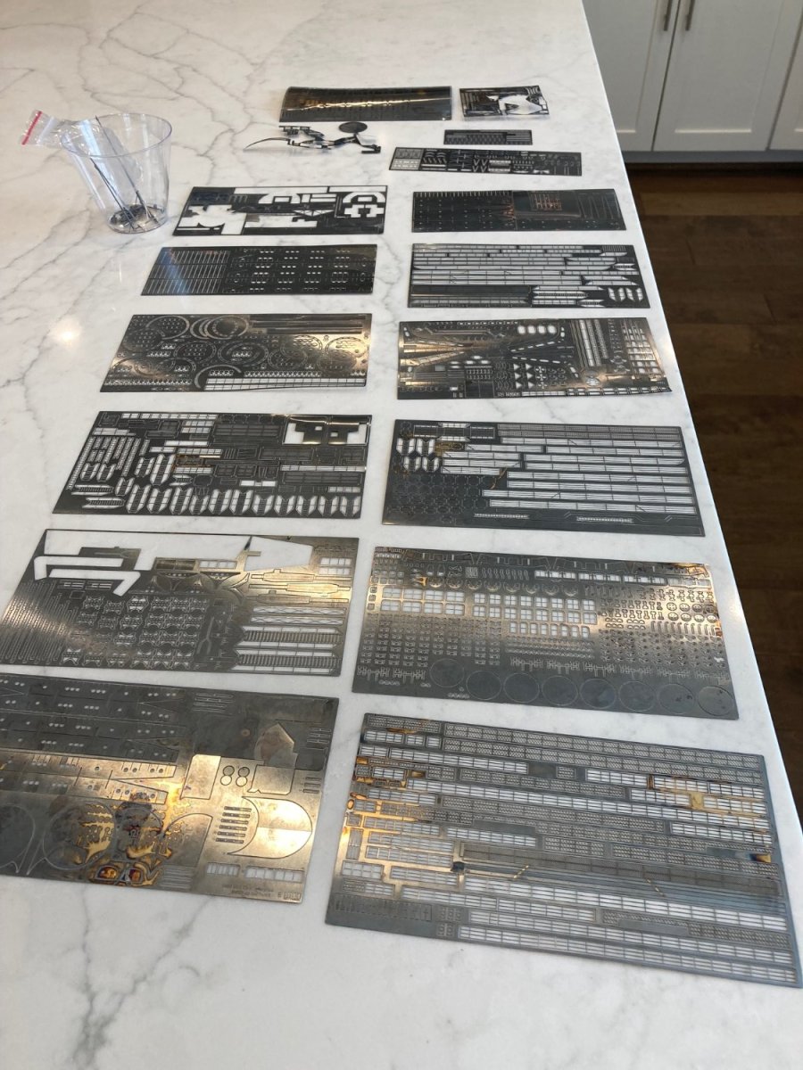
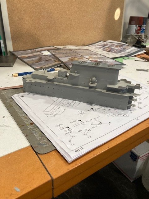
For future builders of this kit, a piece of advice. Look very carefully at all of the brass pieces in a super-detail set so that you understand which pieces of the Trumpeter-supplied plastic is being replaced. This is very difficult with the MK-1 set because of the nature of the "instructions". The instructions are simply a set of pictures of the assembled model with SOME of the PE detail parts identified. It could be my inexperience, but I see a LOT more PE pieces than there are pictures of identified part numbers. The MK-1 PE sheets are very well marked with part numbers, but the corresponding picture sheets seem to be missing pictures of many of these parts and their location. For instance, the PE sheets have 6 different kinds of hatches, but there are "zero" pictures of where these different hatches are located. Trumpeter is no help as their "molded-in" hatches all look the same (and nothing like any of the different types of hatches on the PE sheets. I suppose that this is where one supplements the build with reference materials. IMO, at the price these detail kits command, this information should be included with the kit. When I finally get around to the Missouri and it's Pontos detail kit, I'll find out if there is any difference compared to MK-1. I'm not finding the Midwest Models U-tube videos of the build very helpful. The latest video is focused on weathering of their blue hull paint.
- 154 replies
-
- 5
-
-
- Enterprise
- Trumpeter
- (and 1 more)
-
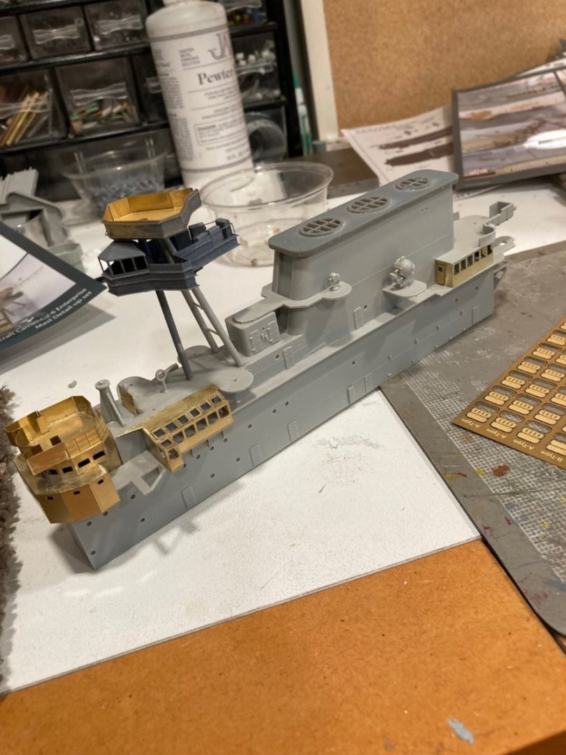
Continuing to work on the Island. Doing the PE pieces that will be painted. I plan to use the Jax Flemish gray on many of the brass detail pieces and apply them after the whole superstructure is painted gray. This is experimental, for me, to see if more of the fine detail of the small brass pieces is preserved this way. I had to pre-paint parts of the structures on top of the tri-pod because of hard to reach parts. My PE skills have improved a lot since my first foray into this with the Amati Bismarck. A lot of this has to do with figuring out which applicator to use and when to use thick v. medium CA. At times with Bismarck, I thought I had more CA than brass on a part. The interior of the hull has been painted, but I'll keep working on the Island until I've got all the parts on I want on before painting. This Island has a lot of the super-detail that one finds on a BB superstructure, but because of the narrowness, it seems easier to get to. Most of the rest of the super-detail is around the periphery of the hanger deck.
- 154 replies
-
- 6
-
-
-
- Enterprise
- Trumpeter
- (and 1 more)
-
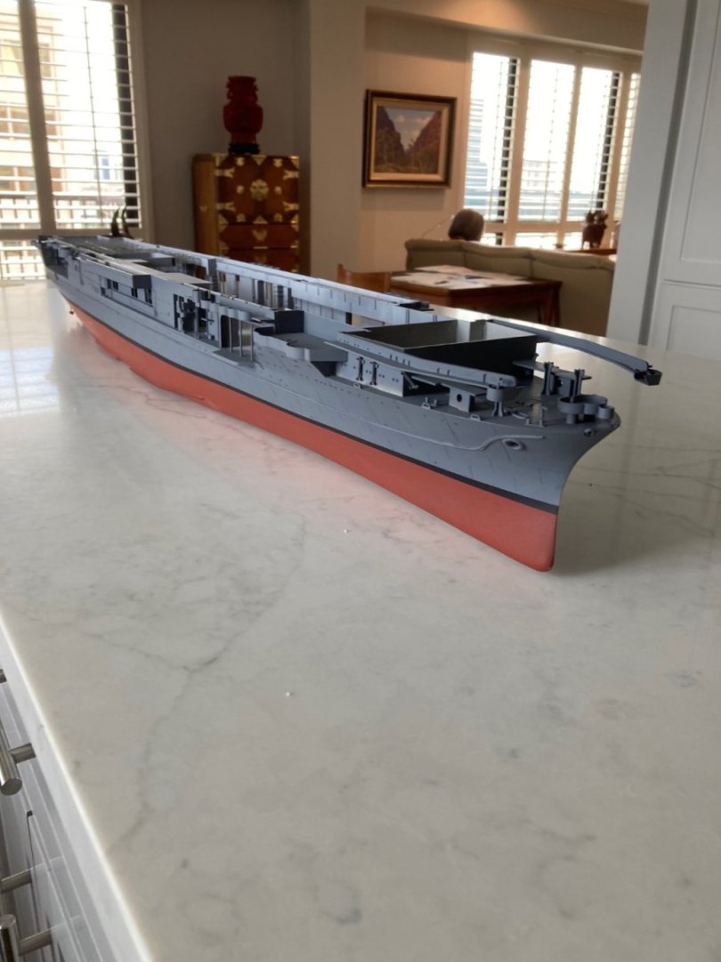
Hull is masked for painting of the interior, which needs to be done before some interior supports are installed. Unfortunately, the current weather conditions have the lower jet stream flowing directly over TX, and the wind makes my outdoor balcony paint booth unusable. In the meanwhile, I've started on the superstructure. All the plastic pieces are in place and some of the major PE parts need to be done before painting. The smallest PE parts, like railings and ladders will come after the first painting. The Amati Bismarck really spoiled me for a super instruction manual. The Trumpeter "instructions" leave a lot to be desired. It's a constant search of previous pages where subassemblies are "sometimes" illustrated. I still have plastic pieces on sprue's that I cannot yet identify where they go--and this is with most of the plastic parts assembled. I am also not thrilled with the "instructions" for the MK 1 details. It's mostly just a series of pictures of the assembled model and VERY difficult to identify numbers for the PE sheets. I have ready in the closet the Trumpeter Missouri and the Pontos detail set. The Pontos set seems to have better instructions, but it will wait until I start that build for a definitive conclusion.
- 154 replies
-
- 6
-
-
- Enterprise
- Trumpeter
- (and 1 more)
-
^^^Thanks for that info, Mike. I've rotated between the Plastruct for Large plastic sections, the MM "Same Stuff" for smaller pieces and the tube Testors when there is a large piece that would "dry-out" the brush-applied cement before it could be properly placed (and the inevitable extra cement that would spread at the edges of a brush-applied joint that would be difficult to clean up). I bought a jar of the Orange back when I was doing Bismarck, but haven't used it yet. I don't know what sets it apart from the other cements, but I bought it because Tamiya seemed to be positioning it as a "premium" cement. I've completed the sides of the Hanger Deck. This was not a simple task as some adjusting the locating tabs of the side pieces and actual length of two of the side pieces is necessary. As I mentioned before, dry-fitting is absolutely essential to work out the assembly sequence and which tabs need to be made smaller to allow the side pieces to take up a proper position. The fore and aft ends of the hanger deck should be first. Everything else uses them as their anchor ends. One needs to cement in the large structure directly under the superstructure next. There is no ambiguity about where it fits and it needs to be firmly in place for some of the more physical efforts on other side pieces later. For me, I got the port and starboard fore and aft side pieces in place next with only trimming off some of the edges of the tabs to get them to firmly seat to the fore and aft ends. It's the long pieces in the middle of either side that needed to be trimmed in length slightly (less than 1/8" each) to fit. This is not a problem because the area that needs to be "trimmed to fit" is a flat section. But, in each case, there is a small locating bump on the back that needed to be removed for a flush fit. Hard to describe, but when you are actually doing it, it becomes obvious. I view this as a casting error by Trumpeter (or they did it deliberately to accommodate building variance). I painted the bow and stern before cementing in the aft bulkhead and attached elevated "box" because subsequent steps will make it very difficult to get paint on the deck beneath the elevated "box". The next several days will see me cleaning up excess cement and masking and painting the interior of the hanger deck. It'll be easier to do before some of the elevator and support beams are added later. I decided to leave as many of the roller doors open as I can to allow looking into the hanger deck. I now plan to put some of the aircraft provided by Trumpeter on the hanger deck where they can be seen. I think I'll also model the middle elevator at it's lowered position with an aircraft sitting on it. There are two of the roller doors that open to a blank bulkhead, so I placed the doors down, there. There were also two places where the very thin between-doors supports needed some reinforcing, so I put the doors in place at those locations.
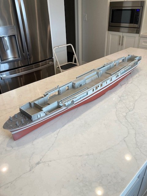
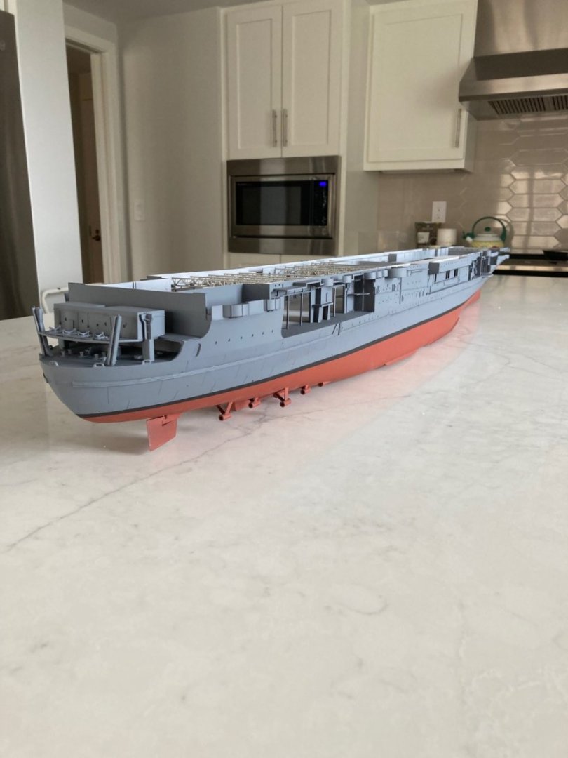
- 154 replies
-
- 8
-
-
- Enterprise
- Trumpeter
- (and 1 more)
-
I had a number of interactions with ADM Rickover. If you have ever heard a "Rickover story", it is probably true. When I was going through Nuclear Power School the first time in 1961 as a white hat Electronics Technician, I groused about how all the electrical controls for the reactor used Magnetic Amplifiers instead of the "modern" transistors. I was told that Rickover didn't want to use any technology that was newer than 20 years because of potential reliability issues.
- 154 replies
-
- 3
-
-
- Enterprise
- Trumpeter
- (and 1 more)
-
I've been dry-fitting the sides of the hanger deck. Absolutely necessary as the little locating tabs and other small areas need to be trimmed to get the pieces to sit tight to the deck. Also helpful to planning which side doors to leave open and sequence for painting.
- 154 replies
-
- 9
-
-
-
- Enterprise
- Trumpeter
- (and 1 more)
-
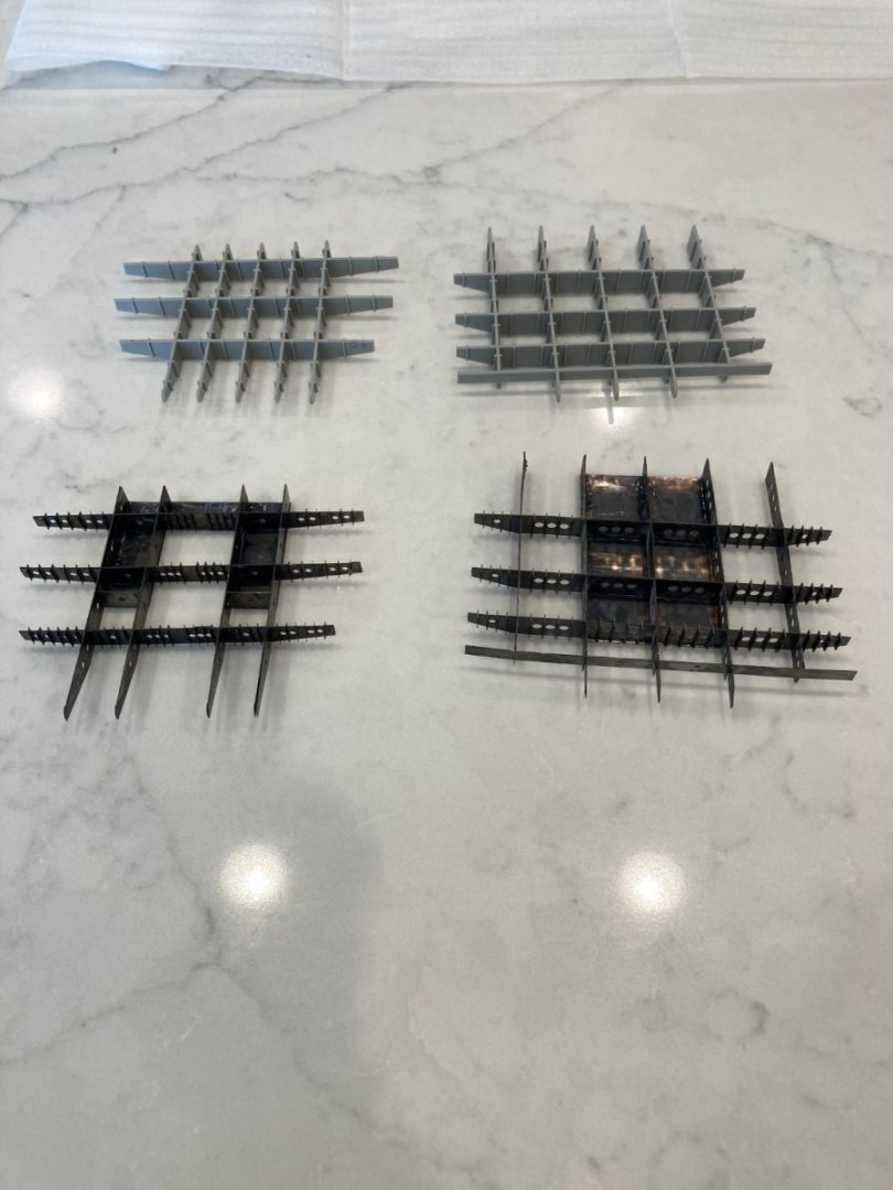
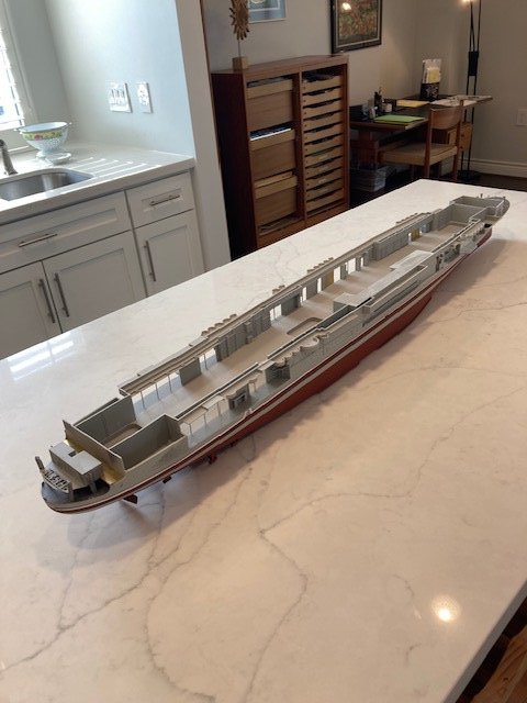
Degausing cables completed. Used .020 on one side and .025 on the other. The .020 does not "fill" the full width of the PE simulation of the cables, while the .025 does. The diameter of the .020 looks to be more scale-like. The added stiffness of the .025 made for an easier attachment of the first cable in a run to the PE brass, but the subsequent "cables" are equally easy to apply. Having the PE brass made a very useful guide for placement of the cables, and it looks a little like bracketing for the cables. The lack of a "step-by-step" assembly manual means one is left to one's own devices on assembly sequence. It's a Rubik's cube kind of thing, for me; as one is juggling how big to go on subassemblies before painting. At the moment, I'm attaching all the smaller plastic pieces to the larger pieces and deferring to later for the PE details. The hanger deck is like the first deck of a battleship, except that parts of the hull extend upwards in front of the internals of the hanger deck blocking a later painting; so these parts will have to be painted (along with internal sides of the hanger deck) before assembling the internals. If this is done after painting, it means using CA glue and not plastic cement for attachment. Also complicating things are roll-up doors that can be modeled open or closed. If open, it will give a view to aircraft stowed on the hanger deck if one peers thru the doors. Decisions, decisions.
- 154 replies
-
- 8
-
-
- Enterprise
- Trumpeter
- (and 1 more)
-
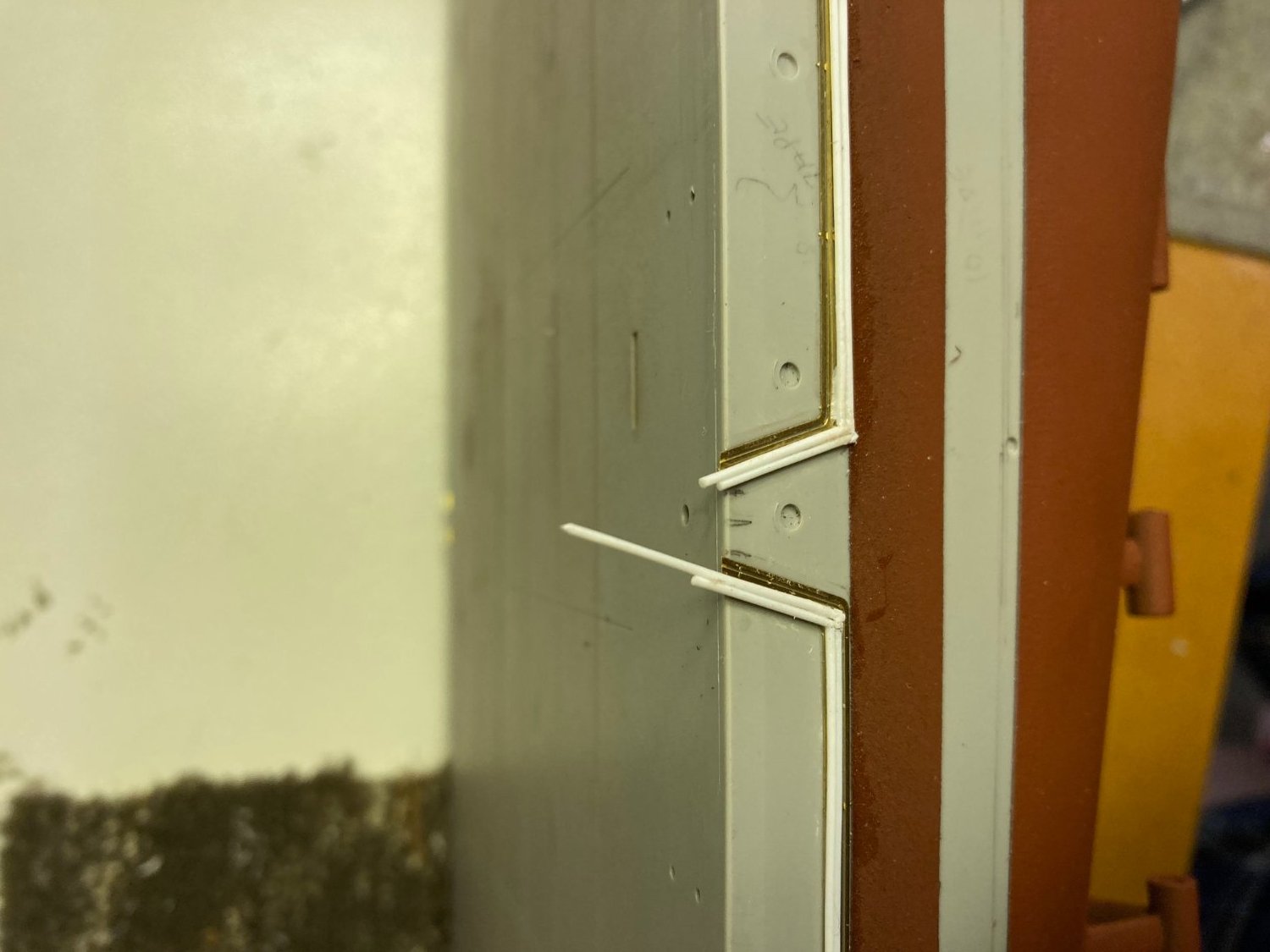
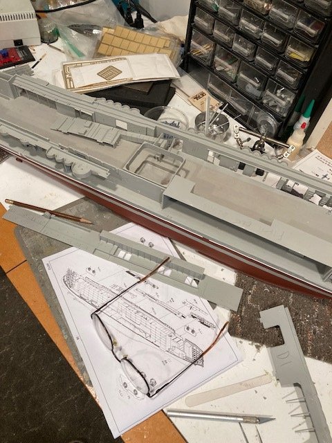
Thanks for the info on prop shafts. I placed the Mk-1 PE detail for the degausing wires, but they looked too flat. The Midwest models guy added styrene rods to simulate the actual wires and I liked the looks of that. So, I added .025" styrene rods on top of the PE brass. Looks good to my eye. But, I only purchased one package of 10 of the .025 rods thinking it would be enough--wrong. Took all 10 for one side, with the left-overs visible in one photo. Gotta buy another package, but it's going to be in .020 size. The larger rods are a little crowded on the PE, and could stand to be a "slightly" smaller dia. Not concerned as it's the opposite side of the hull and only I will notice.


- 154 replies
-
- 8
-
-
-
- Enterprise
- Trumpeter
- (and 1 more)
-
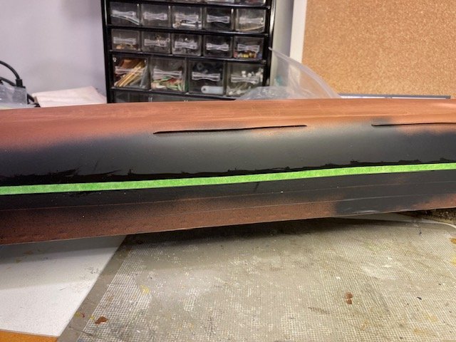
After stripping the masking tape intended to simulate panel lines, but leaving the boot stripe tape in place. Looks like it's going to have the desired effect. 4 coats of the primer gives a good, but not too "good" edge to my fingers and eye. Color coat will tell. Doing the PE degausing detail next. Does anyone know what color the exposed screw shafts should be? I've never seen exposed shafts in dry dock. I wouldn't see a need for anti-fouling paint for an active service vessel, but I don't know. In reading the history of CV-6, she was one of the few "night-qualified carriers in WW II. Too late now, but it might have been interesting to model the dark deck. I'll do a search to see if the dark deck is available as a "deck only" detail. It would be nice to do a 90 deg rotation of the picture, but I don't see a way to do this.
- 154 replies
-
- 6
-
-
-
- Enterprise
- Trumpeter
- (and 1 more)
-
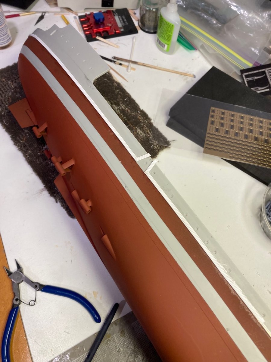
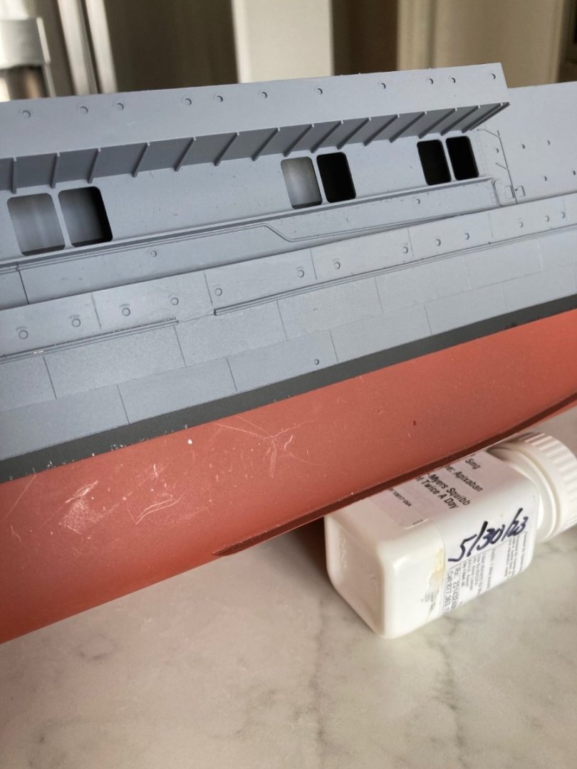
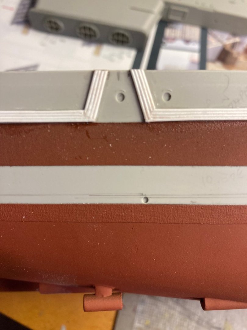
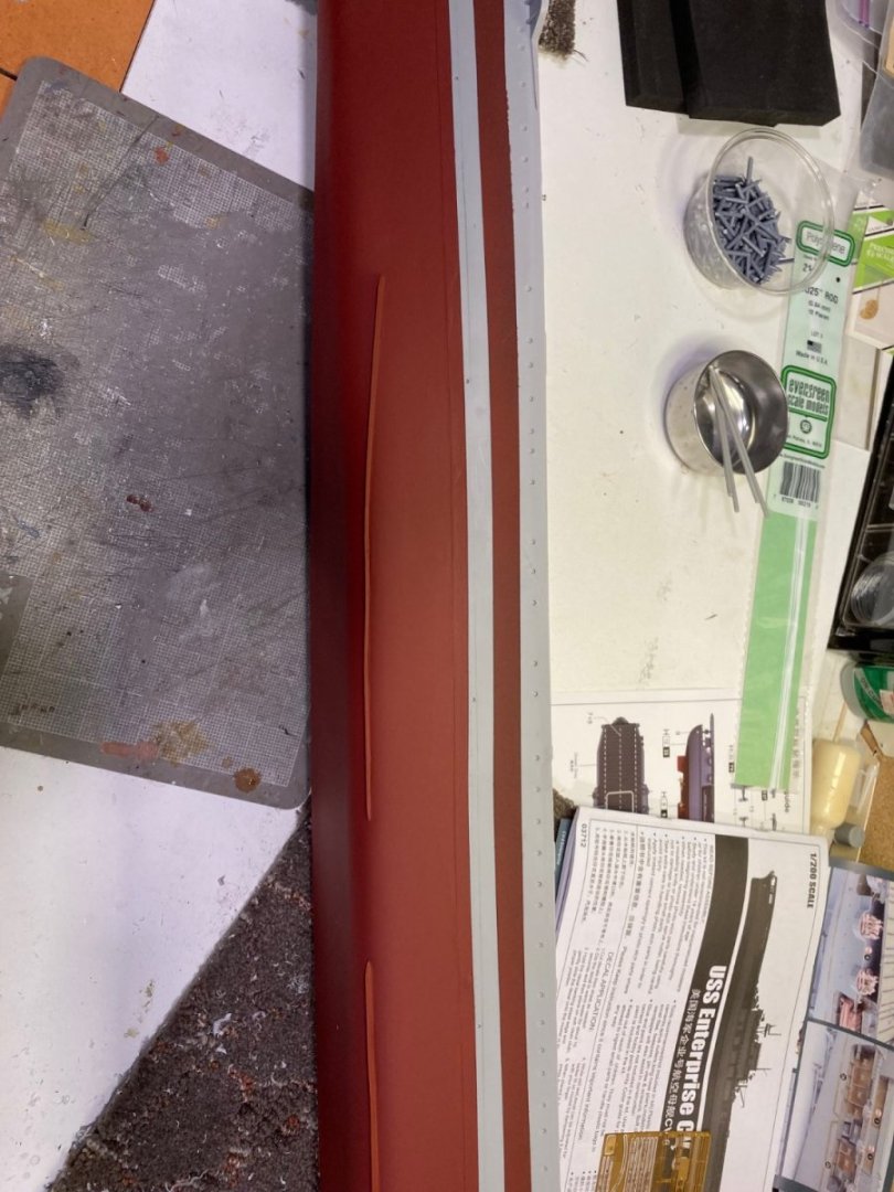
After 4 coats of Rust Oleum rusty metal primer and a coat of flat black at the waterline for the boot stripe, which is masked off with 8mm masking tape. I'll spray with bottom-color next. Won't strip off the 8mm boot stripe mask until after spraying the gray topsides. The shiny bit at the top edge of the masking is where I ran a line of micro-flat to seal the tape edge from edge bleed of the bottom paint--A tip I was given back in the Bismarck build. The bottom strakes still had small gaps at the hull/strake join, so instead of filler, I ran a small bead of medium CA and allowed an overnight cure. Perfect fillets and a MUCH more secure anchor to the hull.
- 154 replies
-
- 6
-
-
- Enterprise
- Trumpeter
- (and 1 more)
-
My memory is that under-construction Cruiser hulls were re-purposed as carriers at the outset. Is that wrong?
- 154 replies
-
- 2
-
-
- Enterprise
- Trumpeter
- (and 1 more)