MORE HANDBOOKS ARE ON THEIR WAY! We will let you know when they get here.
×


ted99
-
Posts
235 -
Joined
-
Last visited
Content Type
Profiles
Forums
Gallery
Events
Everything posted by ted99
-
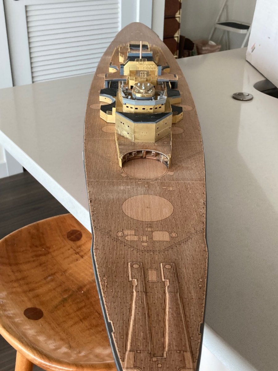
I saw a picture in one of the references that showed a metal edge around the perimeter of the teak deck about 4" (100mm) inside the hull/deck edge. The handrail stanchion "sockets" were welded to the outside of the band. The teak was hard fast to the inside of the steel band. My model has a 1mm gap around most of the model, widening to about 2mm after the bow and stern flares and a little wider than that at the extreme bow and stern. It looks to me like the model stanchions should go about the same depth into the hull as the ladder rungs in the bow and stern PE pieces--not too deep. I intend to drill my .7mm stanchion holes in the hull hard against the deck edge. This is like the actual ship and will give the handrails a little support, as well.
-
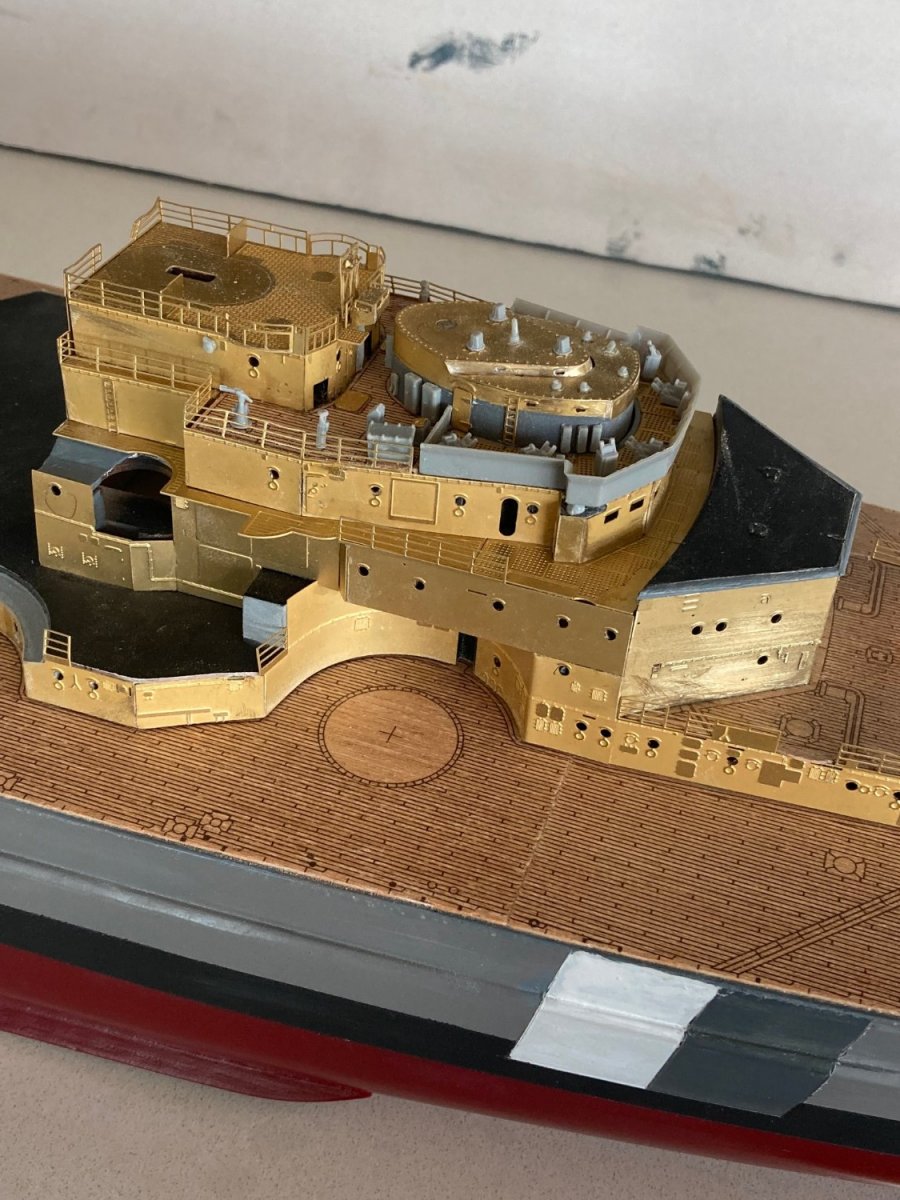
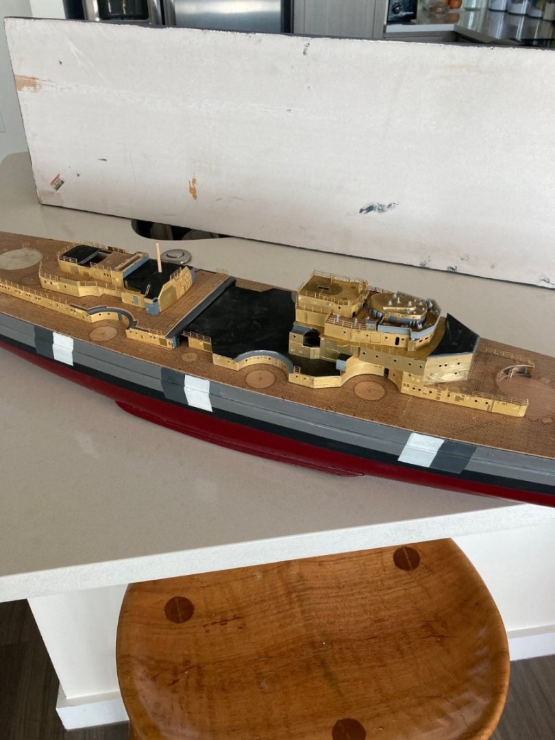
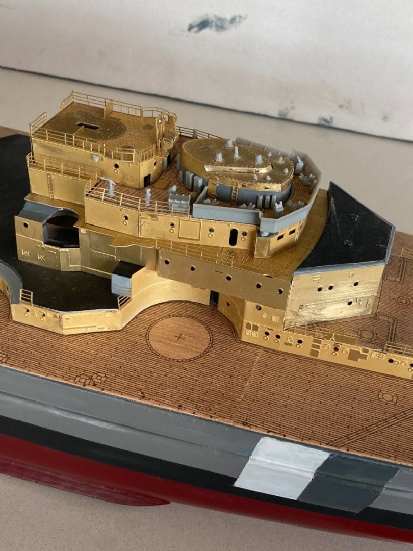
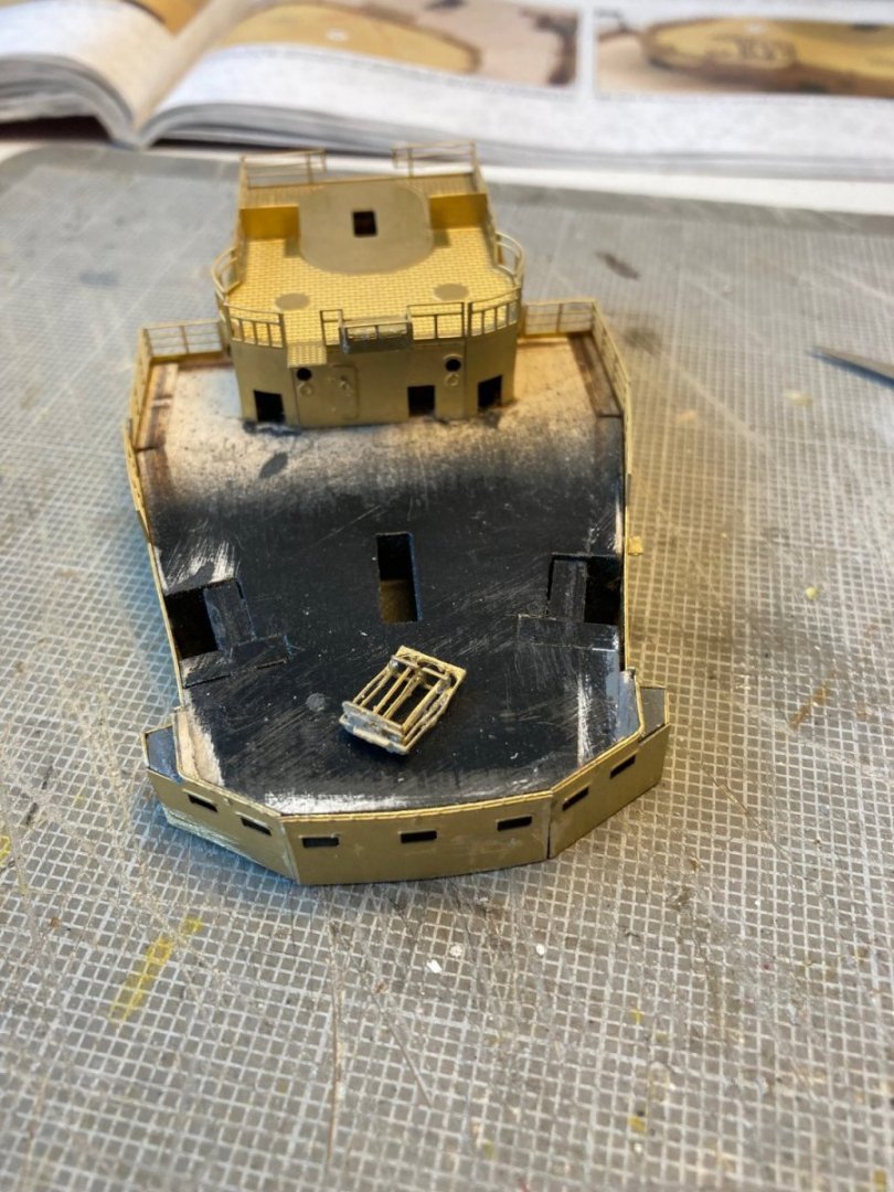
All the major platforms are complete. Now to hours of adding the PE/plastic details. If you see bent railing, I'm leaving them that way until final assembly. Bent over from my grip when sanding. I figure there are a limited number of times I can bend those things back and forth, so I'll leave them alone, for now.

-
Another future builder alert. I suggest that you conform the fore and aft superstructure to the hull profile BEFORE attaching any of the PE Brass cladding. You will be doing a lot of hand sanding (if you don't have a belt sander) to get the base of the wood base to match the hull hogback without small gaps in the middle and it's a lot easier if you don't have to worry about your grip on the structure bending the railings that are part of the brass side cladding. It's easy to file/sand the bottom of the brass sides to conform with the wood. Much more effort in getting the proper profile across the full-width 5mm ply base.
-
That was what prompted me to remark that I didn't know I needed watchmaker skills. Building that thing really improved my skills to the point that I ALMOST wanted to do it again. Interesting how my older iPhone camera makes the grey plastic look blue
-
Builder alert. Aft superstructure PE Brass attachment. On P.31 of Vol1 instructions: Make a note on Step 678 to go to step 688 on P.33 first. It will be much easier to do a smooth wrap around of the upper house if the lower railings that are done in step 678 are not there. Ask me how I know.
-
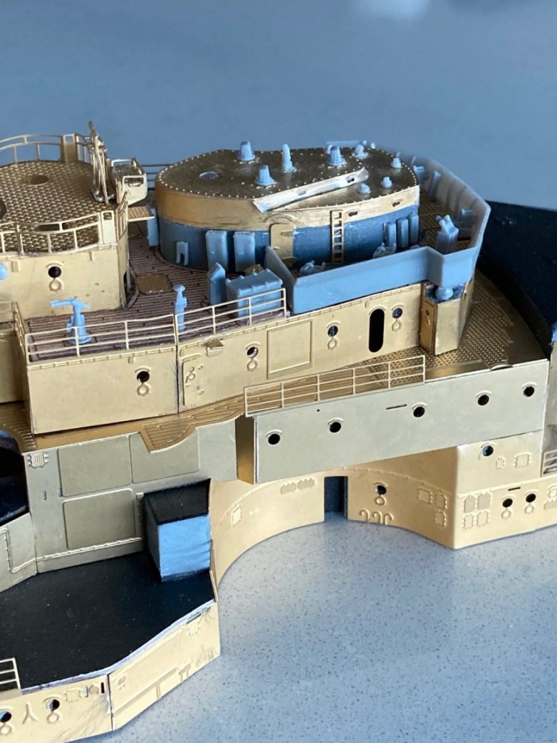
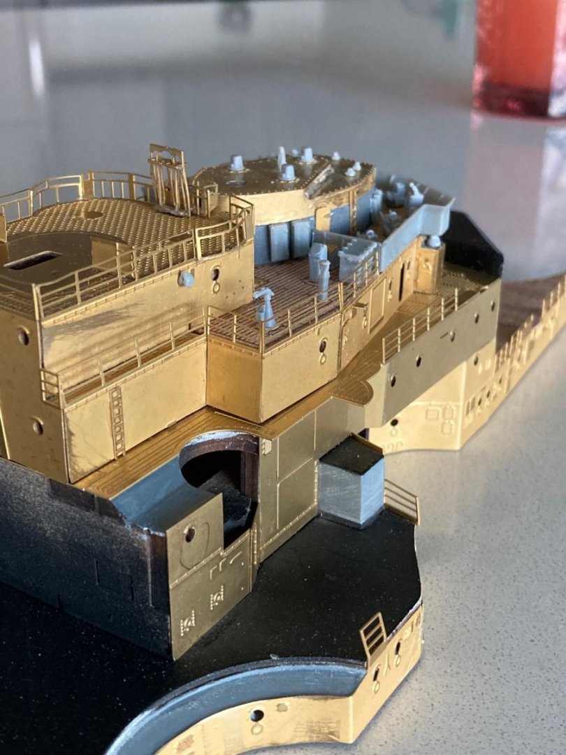
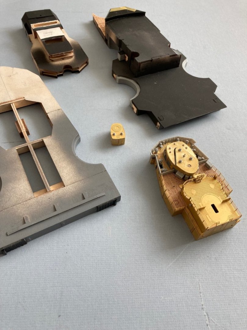
Major cladding done on the forward deck superstructure. Plan to do the same for the aft superstructure before returning to add all the detail do-dads. I hope to have more practice doing PE brass by then. I've never done PE before and so I've taken a very methodical approach and done dry-fitting of the multiple pieces of brass cladding on the superstructure sides. There are as many a six separate pieces to a side. With the dry fitting, it has seemed like the order of assembly of the individual pieces is different from that implied in the manual. For instance, it has seemed to me that starting at the middle of a string has worked out better for determining which of the pieces overlap and which butt together (allowing for beveling, of course). I also find myself messing with the plywood base with trimming or shimming to get the pieces to go together with minimal gaps. The Tamiya file for PE brass has worked very well. It has a finer surface than my normal jeweler's files and works well on the thin brass.
- 126 replies
-
- 12
-

-
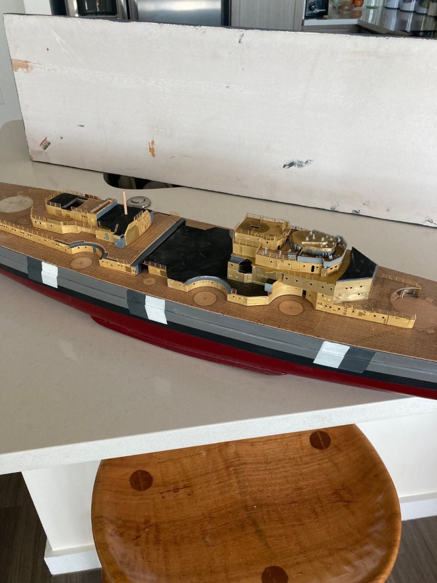
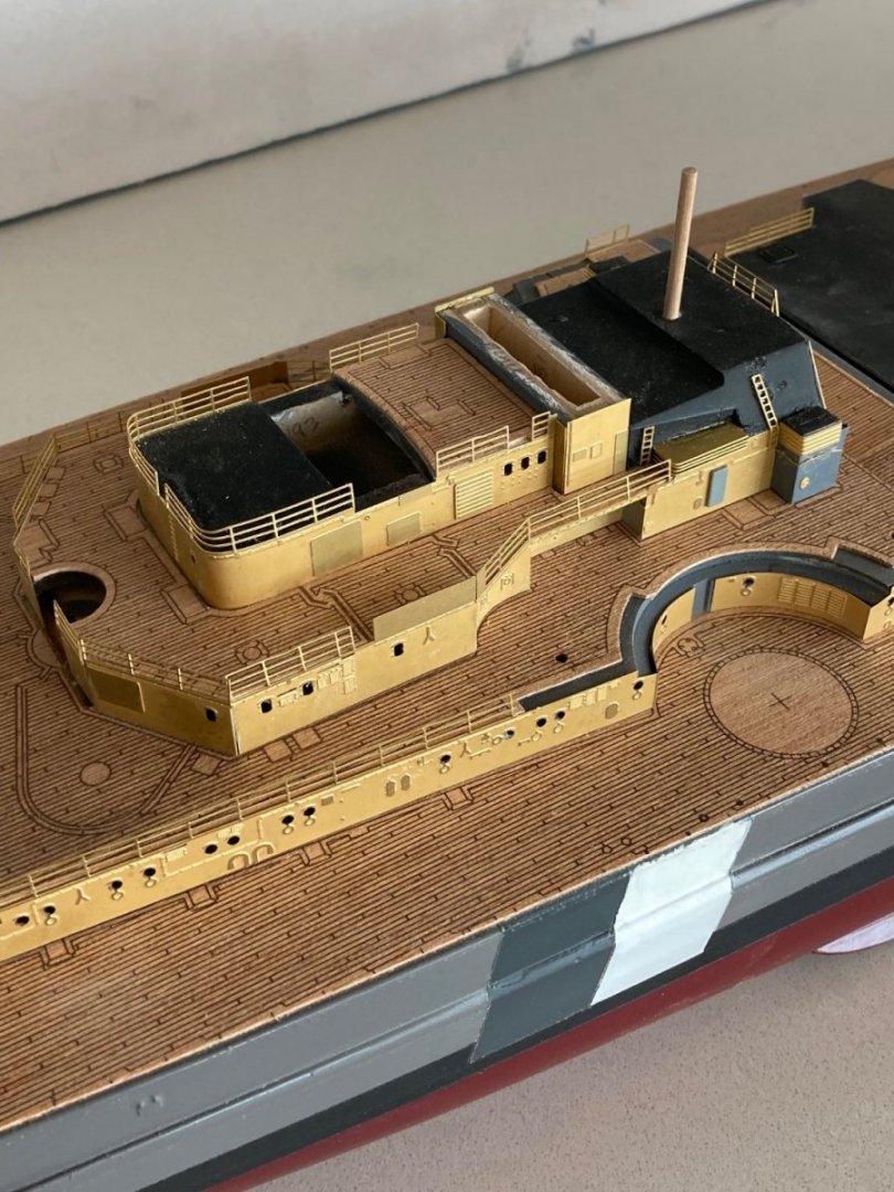
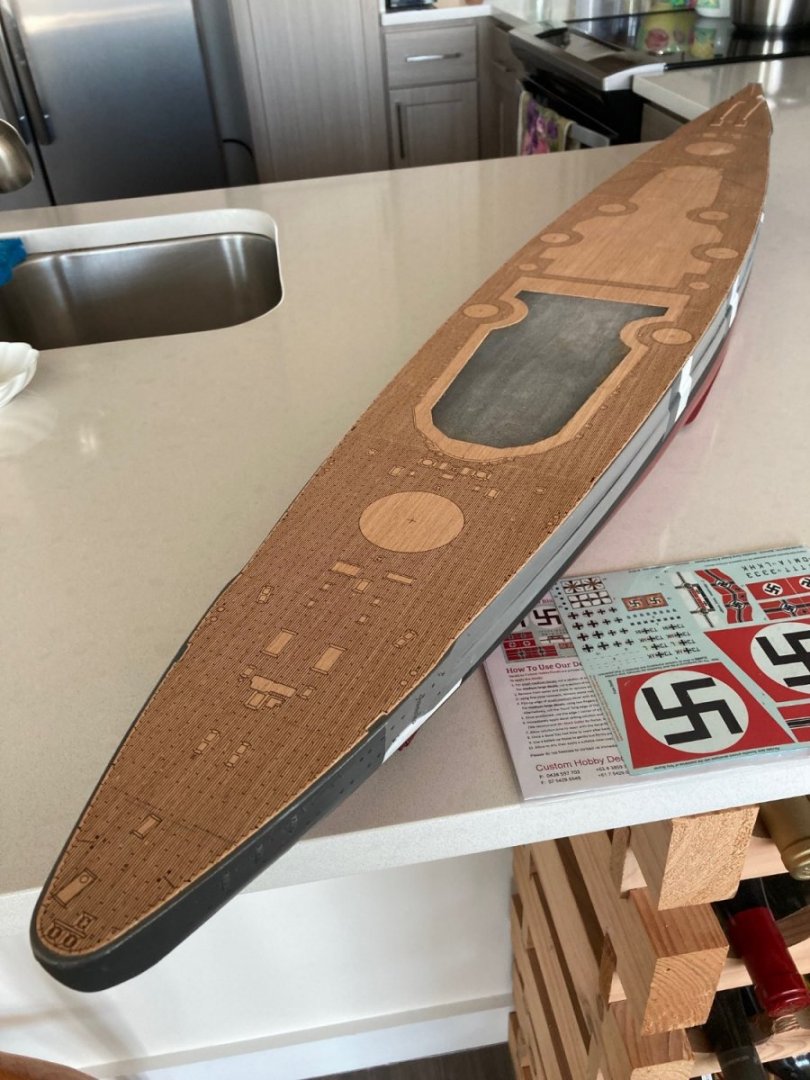
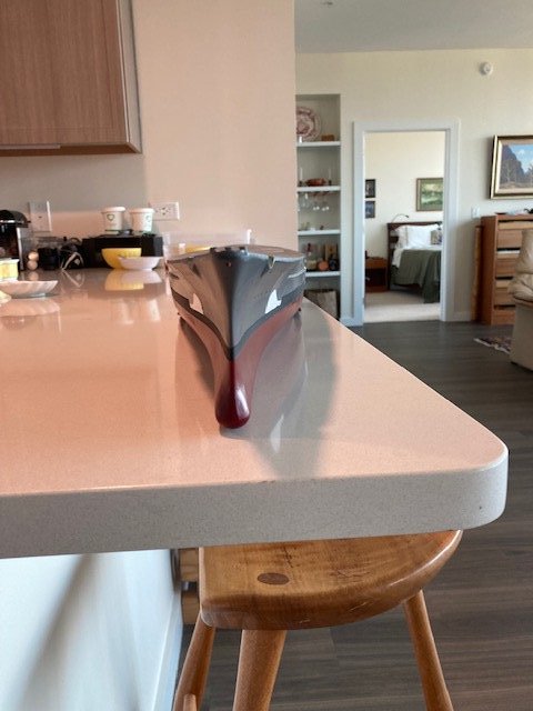
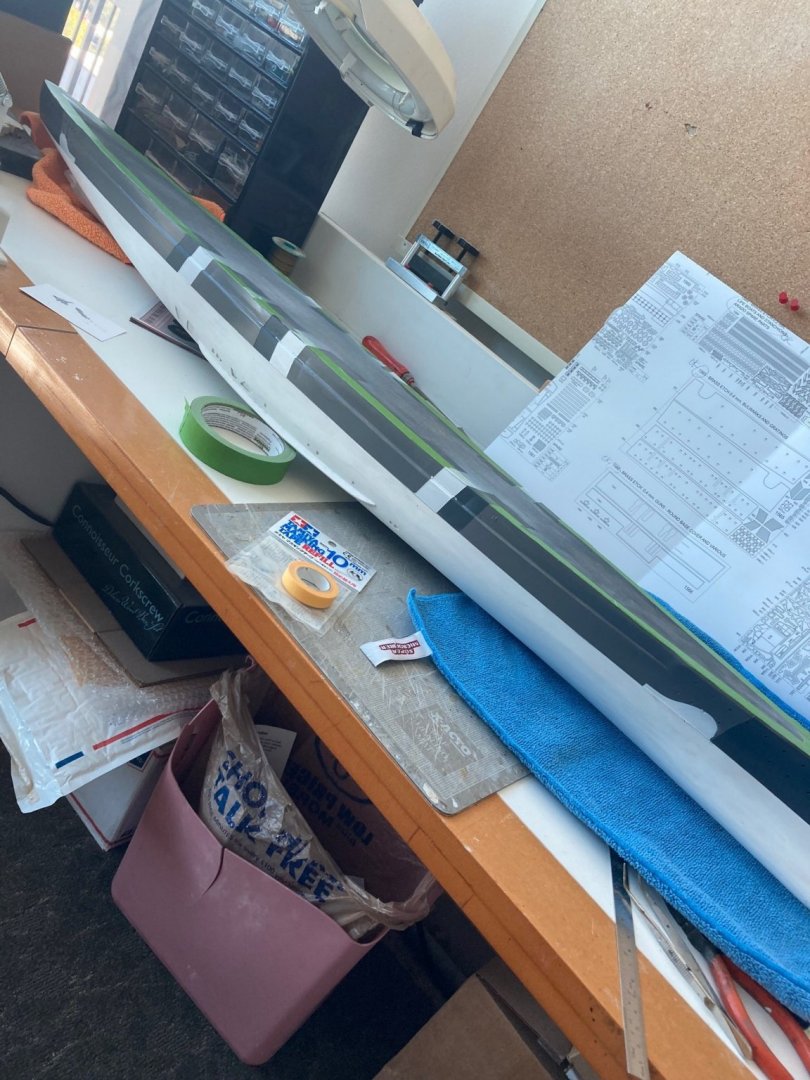
Deck attached. Also shows the 1:200 deck decals from "Custom Hobby Decals" of Queensland, Australia. I'm going to leave the hull alone for a while and come back to improving the camo stripes when I'm in a better mood and less dependent on fickle winter weather for balcony painting. Dry-fitting the deck pieces at the hull sanding stage and tracing their outline on the deck paid off. I have a uniform 1mm edge around the deck between the wood and the hull topsides.
- 126 replies
-
- 12
-
-
Working ahead on superstructure, as I've waited for suitable outside weather for hull painting. Didn't know I would need watch-maker skills assembling PE brass. Work to date. Tried easy PE parts to gain skills. At present, I plan to leave the assembled PE brass unpainted. I think I'd rather look at the PE "in the raw" than have a fully painted mode. To that end, I've been priming and paining any wood that will not be covered with PE brass either grey or black, as determined by the manual pictures. I'm leaving the plastic parts unpainted, where suitable. I may paint the stack after gluing together the two halves, if it looks like I will want to fill the seam, but that will be the base for all the PE detail parts that get attached to the stack that will stay brass. If I persist in this plan, I'll do an overall spray of clear matte paint over the whole model for durability and consistent sheen. Where there are large plastic parts in the superstructure that attach to wood, I've been using epoxy, rather than CA. It offers a longer working time to get the position just right and I just trust it more than my skills attaching large pieces of plastic to the wood understructure. A note to other builders: When you assemble the many pieces of laser-cut ply to fabricate the superstructure pieces, be very careful to get all of the ply pieces fully seated in their respective notches. I found it better to do just a few pieces at a time and allow them to cure before going on to attach more pieces to ensure that each part is firmly in it's slot/niche. The reason for this will become evident as you start attaching the plastic and PE pieces and discover that you left a 1mm gap in a place where a piece of plastic or PE brass attaches. Since I'm using PVA glue for the wooden parts, this has added time to the assembly process. "Tain't a hobby if you hurry".

- 126 replies
-
- 10
-
-
Yes. I've had as many problems with Tamiya paints as you with Rust-oleum. Painting outdoors with wind also means poor results
-
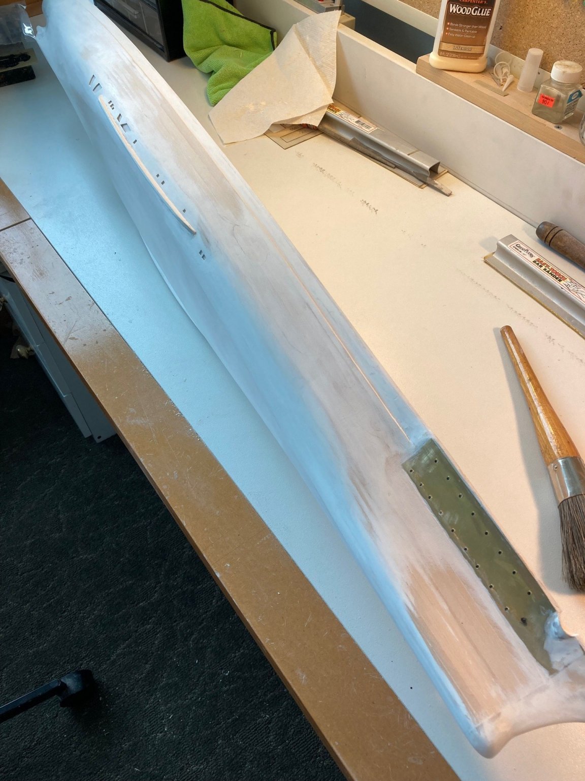
I spent three hours hand sanding the prop shaft fairings so that they conformed with the "as-built" hull. No filler necessary after gluing them on. I'll wait until all the hull work is complete and superstructure is ready for attachment before I put the shafts, struts, props and rudders on. All are conformed to the hull so it's just a glue job. All those parts look very fragile so I'll leave them off for now.


-
Got some 70-80 deg weather last few days, but more wind than was optimum; but I went ahead and painted (with the can closer to the model than desired). Results shown. I used the technique described by Mark Taylor to avoid leakage under the tape and it worked a charm. Used some Badger matte clear polymer paint and had zero seepage under the masking tale--many thanks, Mark! I need to go back and do some touch-up from earlier painting where I did not use Mark's technique--mostly the Tamiya matte white.


-
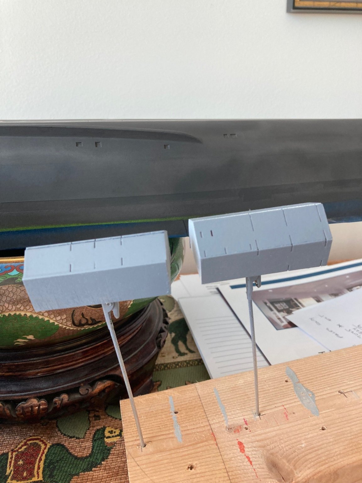
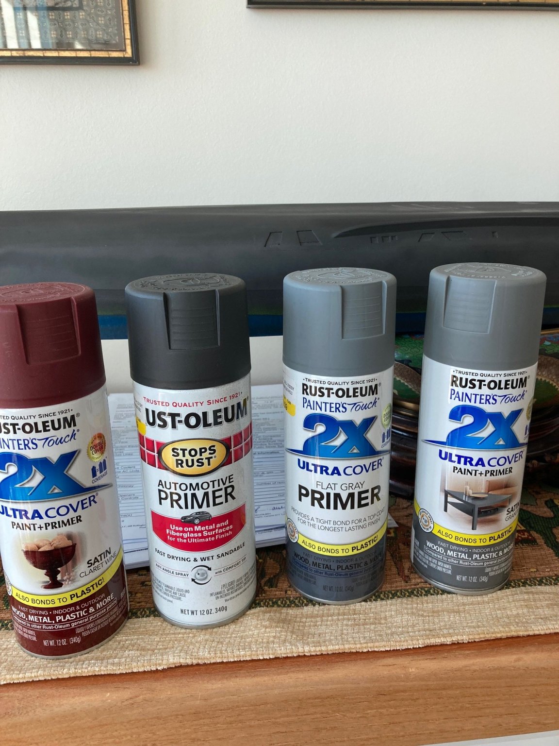
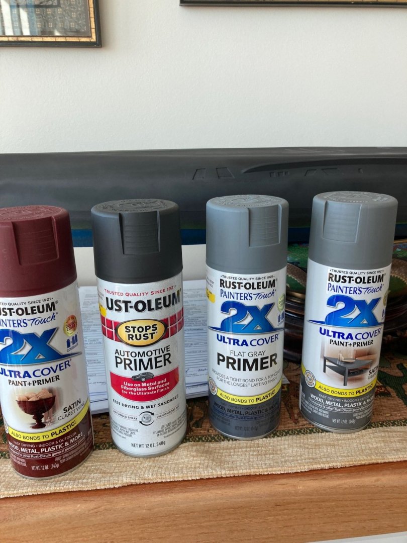
Rod--I read your post on the Rust-oleum paints with great interest, as I had started using them. My experience: 1. There are two types of Rust-oleum primer "Automotive" grade and their "new" stuff that I'll call "2X". I had purchased both a while before I reached the painting stage, so I'm invested in finding out what works. I've attached a picture of the two, plus a can each of the 2X red finish coat and a can of the 2X granite. I've used the almost-black automotive grade primer on the hull bottom and I've used the 2X grey primer on the topsides which I then covered with the 2X satin granite grey top coat. I haven't put the top coat on the "automotive" primer, yet, because of weather. But, it sands just as you would wish it to do. An earlier picture in my build log of the topsides of my hull showed the 2X granite grey top coat over the 2X grey primer. I did not need to sand the 2X primer. It felt like it was soft and had not cured completely a day after painting, but I went ahead and put the top coat over it. The top coat cured hard and very smooth. When I look at the cans, the "automotive" primer says "fast drying and sandable". The 2X says nothing about being sandable, simply saying that it provides a tight bond for a top coat. That's the way it worked for me. At the same time I primed the topsides with the grey 2X primer, I used it for the aircraft hangers that I've built ahead in the instructions waiting for outside painting weather. They have been sitting around for several days and the primer has hardened off in that time to a very smooth satin finish, which needs no sanding. It has done just what I hoped it would do when I selected it over a grey automotive primer. It has a very fine grain and does not fill in. The attached close-up picture of those hangers shows that there has been no build-up or filling-in of the very narrow slots that Amati provided in the hanger sides and top to place PE brass pieces. The slots are very narrow--PE width size. In fact, the finish is so good that I will not use a top coat over it. It's the perfect color and does not look at all like "primer". The fewer paint coats, the better to avoid covering up PE details. In short, I needed to pick my Rust-oleum product for it's intended purpose. If I am going to sand it as part of the process of getting a smooth surface, use the automotive grade. If I am satisfied with the substrate finish and what I want is maximum adhesion of a top coat, I'll use the 2X for it's very fine grade and smoothness, which does not need any sanding. Note that I have been using white gesso brush-applied and sanded with #150 grit sandpaper to arrive at my desired painting substrate. I have not been putting on coats of primer and sanding between coats. I can brush on gesso in the house, rather than waiting for outside weather to be suitable for spray can painting. Based on my experience, to date, I wouldn't be using the automotive grade primer at all since I don't need to sand my primer as part of the finishing process. I really like the colors of the 2X Rust-oleum paints and their "fineness" which doesn't hide details, so I will be using the 2X primer going forward for it's intended purpose of providing a tight bond for the 2X top coat. Except, I don't expect to be putting a top coat over the grey 2X primer I've painted the superstructure with. So far, it looks perfect but there is always time to use the 2X granite top coat if necessary. Topsides are done and I'm in the multi-step process of painting the waterline stripe and bottom, weather permitting, and I'll cover this in detail in my build log.

-
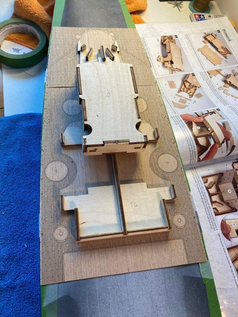
Another manual error. On Vol 1, page 45, plate 201. The picture shows the rear of the bow superstructure aligned with the edge of the printed wood deck. WRONG. If you do this, none of the subsequent pieces will fit. It's too far back. Glue piece #79 (manual has this at a later time) to the rear of piece #76 and it is the rear of this piece #79 that aligns with the edge of the printed decking. Otherwise, the rear part of the front superstructure will be 4mm too far aft.
-
I was fortunate in discovering this at the final sanding stage. I used a #11 knife to cut the outer edge on a bevel. If I had discovered this at the planking stage, I would have been able to sand in the 45 deg bevel before gluing in the 1 mm board. By doing it later, I was reluctant to do the bevel across the whole top of the board, because of the risk of grooving the 2mm board at the juncture of the bevel. Looks OK as is, but could look better if I had beveled the top 1mm second layer plank before gluing it.
-
Got a break in the weather today and I was able to "complete" the above waterline painting and strip the masking tape. VERY disappointed in the Tamiya spray paints and in particular, the 10mm wide masking tape. I used this around the white camo stripes thinking that it's thinness would make it very compliant at the belt line armor. NOT. It's much worse that the green "Frog Tape" that I used at the waterline and grey stripes. You can see all the bleed thru at the joints of the white stripe. I used the green frog tape everywhere else I had a had a cut line and no bleed thru. Looks like the Matte White Tamiya paint needs three coats over light grey primer, rather that the 2 it's gotten, so far. I also had some crazing--again over fresh Tamiya light grey primer. The Tamiya paints are relegated to the "non-critical" bin. The Rust-oleum paints have a better spray nozzle, better coverage and cost half that of Tamiya. The provided "stencils" for the camo are pretty close to useless. The stickum isn't very strong making bleed thru possible. Also, if you are going to use the "wave" pattern at the bow, do not mount the ladder rungs in the area of the cutout. The stencil will not adhere in that area over the rungs. Do the rungs after the stencil painting. I'll be masking for a matte black waterline stripe next, after some cure time, and then the bottom paint.
-
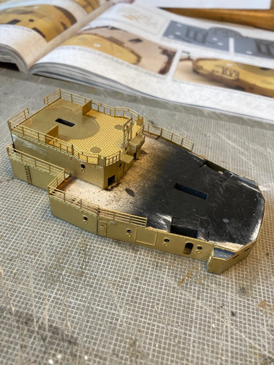
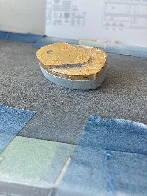
As promised. You can see the mess that the filler left by waiting until the top PE brass piece was attached to fill the gap. Waiting for a small brass wire brush to come from Amazon to remove this excess. If I had filled the gap before the top was attached, I could have used a thin smear of Tamiya putty to level the gap at the top of the filler with the top of the PE brass --only the thickness of the PE brass to be added. I filled the exposed wood base and painted with Tamiya light grey primer awaiting further construction. For those of you not looking at a construction manual, this may not be clear; but you aren't the intended audience.
-
My principal goal in this builder's log is to provide the benefit of hindsight to other builder's of this kit. Places where: "Now that I've done it, I see where I could have done it better". To that end, while waiting for painting weather outside, I've looked ahead and begun building some of the superstructure assemblies. Having never done PE before, I decided to build the "Front Control Station", whose assembly is described on P. 75 of the instructions. It has PE brass adhered to a wood base, is small and has a combination of curved and flat PE brass for good learning. I suggest that any future builder annotate your instruction book at the appropriate page with these notes, so that you can consider them when you reach that stage of the kit construction. After completion of Step 364, I suggest that you fill the gap between upper and lower step wooden pieces (after PE brass #781 and #783 are attached) and smooth it. If you wait until the top cap #785 is attached to do this per the instructions, you will have great difficulty filling the gap without a lot of mess and there won't be much support for the filler. Secondly, PE pieces #781, #782 and #783 should be glued exactly even with the tops of the wood supports, or a little over so that they can be filed down to flush with the wood. The two top PE pieces #784 and #785 are exactly flush with the outer edges of the PE brass sides and if there is no gap between the top and those brass pieces, the two top pieces will be so closely aligned with the sides that they look like one piece. I'll follow up with a picture of this in a new post--I forgot to load the photo in my computer.
-
Rod--Senior moment for me. I was having trouble remembering what Glen's name was before (Lewis in my time). Worked many times with the Center Director, who I remember as Larry, but can't remember last his name. He ended up being "fired" by Carl Lewis after Truly (who was protecting him) got fired. Why is another story. Your questions: 1. I sanded up to the edge of the PE brass, but there was always a little sanding overlap at the edge of the brass and filler for the gap between the PE and second layer. Of course, the porthole eyebrows were scuffed by the sandpaper. I was able to use a #11 hobby blade to scrape off the filler that obscured the eyebrows and that got into the portholes. None of the 150 grit sandpaper marks or knife scratchings showed through the paint/primer. 2. Most of the time, the filler went into the 1 mm gap I left between the second layer and the poly pieces and I sanded right up to and over the poly with 150 grit paper. I too had to build up the bow poly piece in exactly the same place as you with filler. It was a chore to get the filler fillet sanded down to the feather finish needed for painting, but the Famowood did this perfectly. My final sanding before priming was #150 and I didn't have any sanding marks after the primer was on. The gesso I used as the final sanding sealer coat to give a uniform absorption surface for the primer was also done with #150. I originally planned to use #220, but didn't seem necessary. 3. Yes, the deck edges should be even with the upper edge of the hull. Fill any visible seam and the final result should be just a little rounding at the deck edge to facilitate paint adhesion. The wood decking pieces should come up to about 2 mm from the hull edge. That gap is painted the same color as the grey hull. Later on, the deck railing stanchion holes will be drilled into the 2 mm gap right at the edge of the wood deck. Looking at pictures of the Bismarck, there was a steel edge around the outside of the wood decking and the stanchions were attached to this steel edge. I dry-fit all of the wooden decking and traced the edge of the decking onto the deck and used that as my guide for where the hull/deck edge should be. I sanded down the edge of the hull/deck to 2 mm of where the edges of the wooden deck were. When I painted the hull grey, I made sure the paint extended over the edge and about 1/4" into the deck for this grey edge that will show after the wood deck is placed. I'm doing the camo stripes and I masked the deck edge so that the 2mm grey edge remains grey. No pictures, but in my experience, no Bosun would bring the camo color up over the deck edge.
-
Concur completely with your comments on the difficulty in blending the second planking to the ply/PE combo and the poly pieces. Just as you, I had to use some filler on the poly at the bow. In hindsight, trial fitting at the first planking stage and adjustment of the first planking thickness at that stage might have avoided this, but at the stage You (and I reached), it was too late. Future builders beware! I also think that the first layer of planking at the bow under the ply pieces should have more concavity sanded in to eliminate a "step" at the lower edge of the bow PE brass. The bottom edge of the brass intersects with the second layer of planking at an angle, rather than a smooth curve. Again, this doesn't really show up until you prime the hull, and then it's too late. Rod--I like your color-coded belt armor picture. If I decide to scribe in dummy joints (the belt armor was designed to be removable in the shipyard to repair battle damage and was not welded so as to minimize damage to one section translating to an adjacent section), it informs where the lower horizontal break line should be. I'm currently painting the hull, but it's slow going because of my need to allow curing time before putting masking tape over fresh paint, plus waiting for weather to be suitable for my balcony paint "shop". The gesso did a good job of filling all the "wood" artifacts such that it now looks like plastic. The irony of going to all the work of making our wood hulls look like plastic is not lost on me. One wonders if the "better" approach is to use one of the Trump plastic kits with Pontos super detail. My next project will be the 1/200 Missouri with Pontos to try this out. I think in a perfect world, I'd like to try a plastic hull with wooden/PE superstructure like the Amati kit. Did you bevel the top edge of the belt armor? Can't tell from the pictures of your model. All of the pictures I have seen of the ship has the top of the belt armor at about a 45 deg angle down.
-
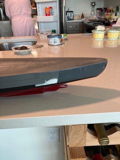
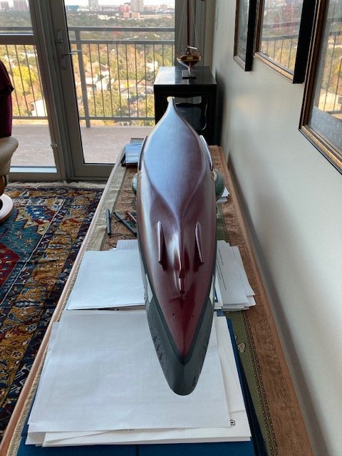
Rod--Coincidence. I started at NASA as Deputy Director for Facilities Engineering at NASA Hq as part of the Challenger recovery efforts (went to Glenn many times before it was Glenn), became Special Assistant to Richard Truly when he was Administrator and when he was fired by Bush 41 I assigned myself to be NASA Representative to Australia at the Embassy in Canberra. Retired from there in 1997 and remained in Australia for the first five years of my retirement. Been a while since my last post. First, because I was waiting for shipment of a particular color spray can of paint; and when it came, waiting for weather. Attached pictures are of my "spray booth" on the balcony of my 18th floor apartment. Of course, the weather was perfect (Houston) while I was waiting and then turned lousy just when the paint arrived. Perfect today: 60 degrees, bright and sunny with no wind. After a little research, I've decided to model my Bismarck as it appeared on May 19, 1941 when it departed the shipyard at current-day Gdansk (occupied Gdynica in 1941). It had the hull camo, only, with dark fore and aft and the false bow and stern waves plus the red white and black swastikas fore and aft. This was Bismarck's first (and last) combat deployment. It stopped near Bergen, Norway on May 21, 1941 where the crew painted over the hull camo. On May 22, 1941 Bismarck departed the harbor near Bergen and while underway the deck swastikas were painted over. Robert Ballard photographed the wreck of the Bismarck in 1989 where he found that the black paint over the deck swastikas had dissolved, exposing them. I guess that the crew hadn't used a heavy-duty black paint expecting to restore the deck swastikas when Bismarck returned to where "friendly" (read German) aircraft cover was available. He reported the teak deck planking as being in excellent condition, as contrasted to the pine decking of the Titanic; so that answers my question about whether the Germans removed the teak decking during combat deployments. As I mentioned earlier, my "workshop" is a corner of a bedroom and I've gotten rid of all my spraying equipment, so I'm slave to what is available in spray cans. I concluded that the Tamiya color "German Grey" is good for the near-black ends of Bismarck and the grey camo stripes plus their "Matt White" for the other camo stripes and false waves. The hull grey is describes as RAL 7000 in the color chart in the instructions and an internet search reveals this as "squirrel grey". I couldn't find any source of spray cans of this color, but I did find a Rust-oleum color called "granite" in a satin finish that looked pretty good. This was the color I couldn't find locally and ordered from Amazon. I've included a picture of the paints I am using. The rust-oleum dark grey automotive primer (almost black) has worked well and does not cover up detail. I'm going to try the rust-oleum satin "claret wine" as the underwater color. We'll see how that works out when I do it. I've also gotten a can of rust-oleum matt clear to do an overall spray at the end for durability and to be sure that the finish has a consistent "gloss" from color to color. I'll see if I do that when I get to that stage. Pictures show the model with the granite grey spray done and the ends plus stripes masked off. What looks like darker patches on the hull are in fact shadows. I'll give the grey paint a couple of days to harden off before I mask off the center to spray the ends "German grey". I'll use that time to mount the ladder rungs and deadeyes in preparation to spraying. With regard to the "Flexy 5K " CA glue: I've been pleased with the thick for attaching the larger PE brass sheets to the wood hull. I think the residual flex is good for the differential expansion rates of wood and brass, which might cause eventual fatigue to a hard-setting CA glue. I am less happy with it for the small details like the ladder rungs. I'd like a hard set up for them because the profile of these rungs are such that one needs to file the PE sheet "tab" off the middle of the rung after the rungs have been attached. This works a lot better if there is a hard set between the rung and the brass undersheet.


-
Just did a job on the top of my 22-story Condo. Cost $100K for one day, including setup and takedown. Takes another crane almost as big for setup and takedown
-
Rod--you are right about needing to know the hull length. That info was available for major warships from pre-war public (or MI collected) data. When I went thru Sub school, there weren't enough nukes to send one for a week for newbie training, so we had the last of the old WW II diesel boats for a week of training near Puerto Rico. They had the old analog Torpedo Data Computer for setting up the data to the torpedo. This required a lot of data to be entered by three people at the settings of the TDC, gained by the person on the periscope. You would estimate speed, angle on the bow, range and bearing through multiple periscope observations. The TDC would "track" the target based on those observations. Each subsequent observation would then be compared to what the TDC estimated from the last input and the person on the scope (Sub Captain IRL) you would adjust his "estimates" for speed, AOB and range based on the difference between what the TDC predicted and what you observed at the next sighting. A lot of "art" and mental calculations for this. When you were satisfied that the parameters entered in the TDC were equal to what the target was actually doing, you would fire the torpedo when you were within range. I'm sure that this TDC was very similar to what was used by the German Navy. A battleship had much better data than could be obtained thru a periscope because of wide-base rangefinders, and then radar. But a Battleship was engaging at the horizon miles away while a sub engages at much shorter ranges. I'm proud to say that I was top of my class with a MOT hit (middle of target) with an old steam-powered torpedo. Today's torpedo's are all guided, but with a much smaller explosive load. A modern nuclear sub is an anti-submarine weapon, where even a small explosive charge is lethal. The watchword in the submarine service is that if you are detected, you are dead. A nuclear sub engaging a surface ship is off-mission. In the rare case where it happened, the sub would launch a undersea-launched cruise weapon from a stand-off range. I particularly like the painted-on bow and stern waves. I can tell you from experience that it probably would work for a target at the horizon being observed thru a periscope. Visibility in North Sea weather ain't great from periscope height.
-
I've sanded all the filler seen in earlier pictures off. Would have been simpler to have just worked with sandpaper alone from the beginning. Still sanding, gessoing, and sanding again. I think your planking pattern is better than the one shown in the manual, Rod. Puts the majority of "joins" at the side/bottom interface. This is an easier area to sand to the proper profile. The manual technique results in the planks having both a curve and a twist as they lay aside each other and the twist makes for an edge sticking up at every plank and lots and lots of sanding. Most of my pain with hand sanding on the second layer has been with this raised edge. It's easy to sand filler put in gaps between flat planks, compared to using filler trying to level with raised edges. The technique I used on the second layer at the bottom of the hull has a similar join at the centerline as that you achieved at the hull bottom/side join and it was a breeze to fill and sand. My judgement is that the best planking technique has as little "sideways" curve as possible in planks. Many of the planks in my technique had simultaneous sideways curve and hull shape curve. Rod--good move on gluing the nine center deck pieces together on a board before gluing them to the deck frame. Much easier, that way, to get this section exactly centered on the frame. I wonder if the mid-deck is in so many pieces because of the hogback? But, that doesn't explain the nine planks.