
Reverend Colonel
-
Posts
24 -
Joined
-
Last visited
Content Type
Profiles
Forums
Gallery
Events
Everything posted by Reverend Colonel
-
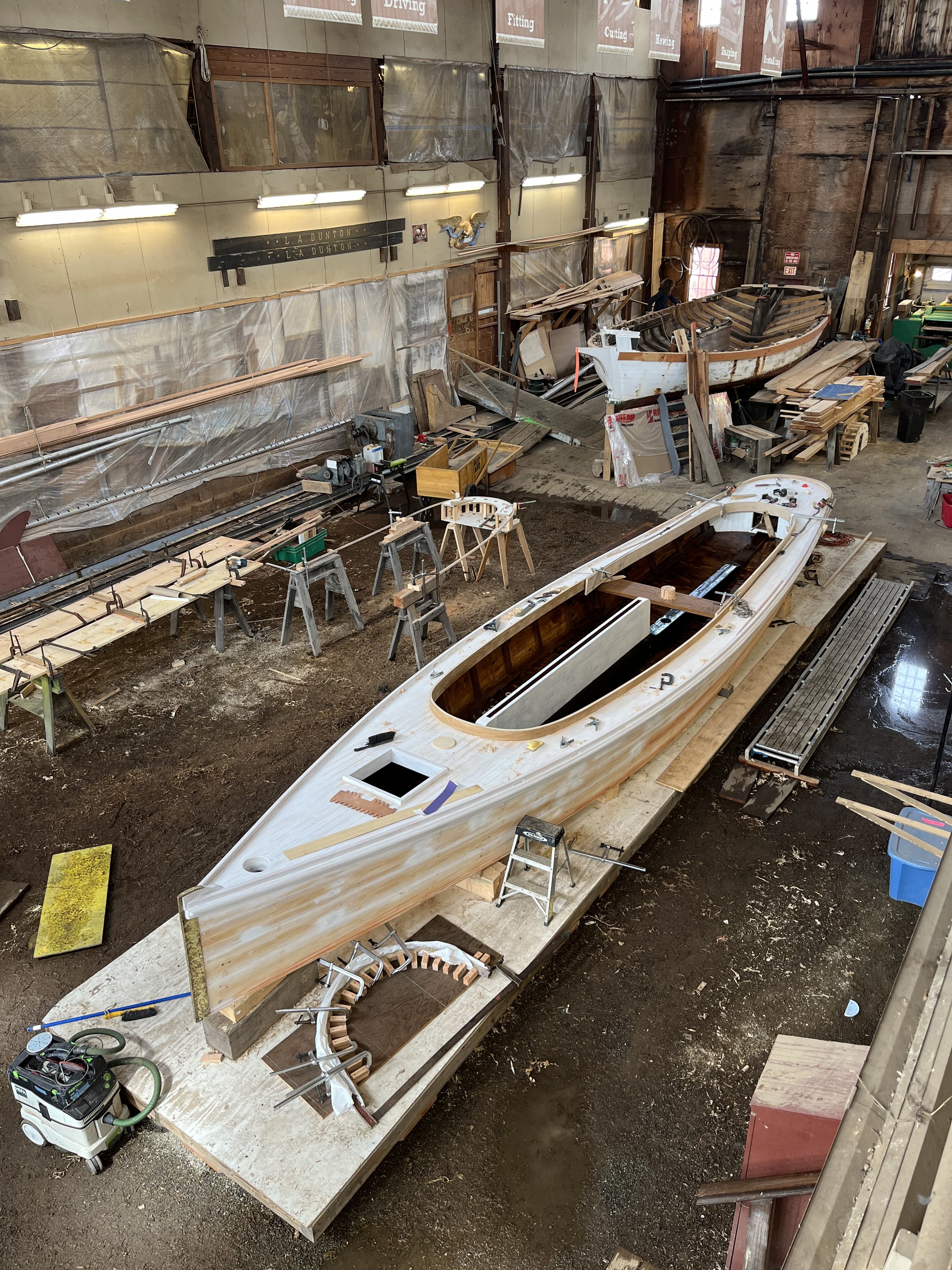
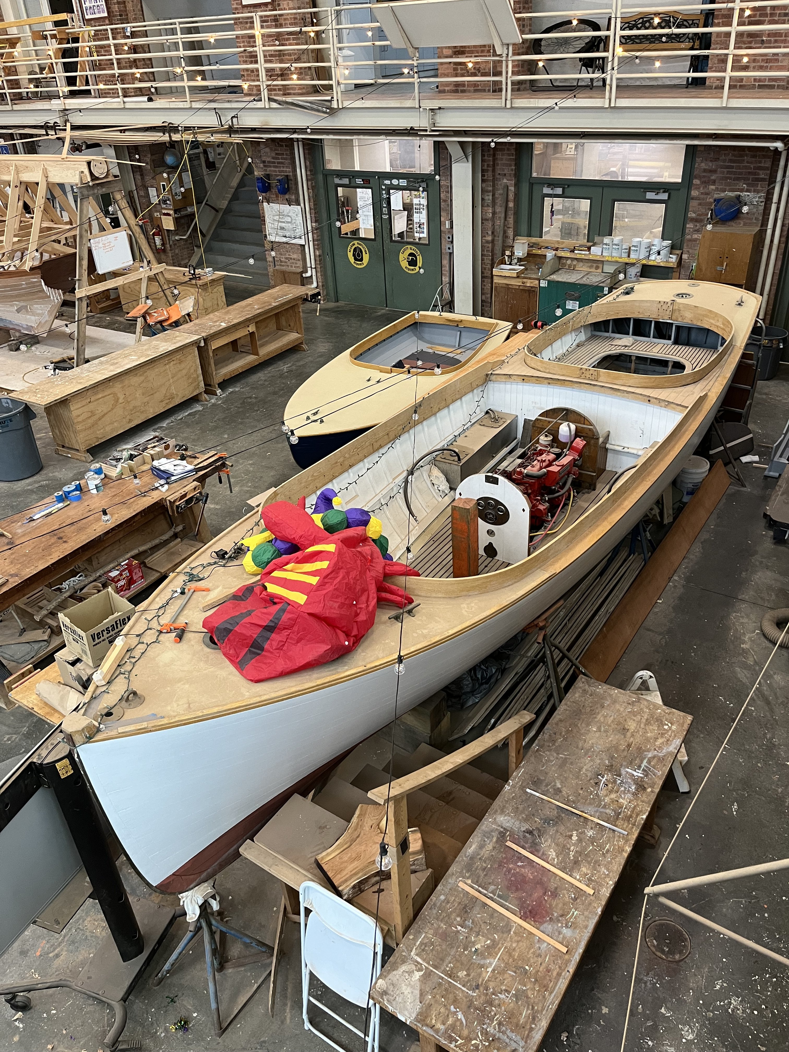
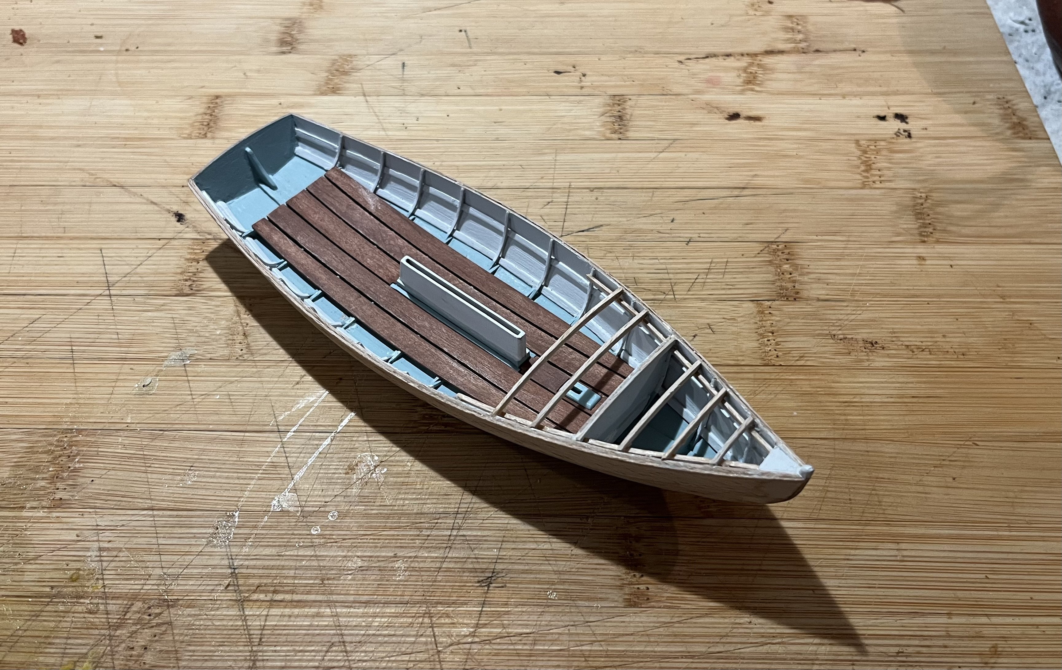
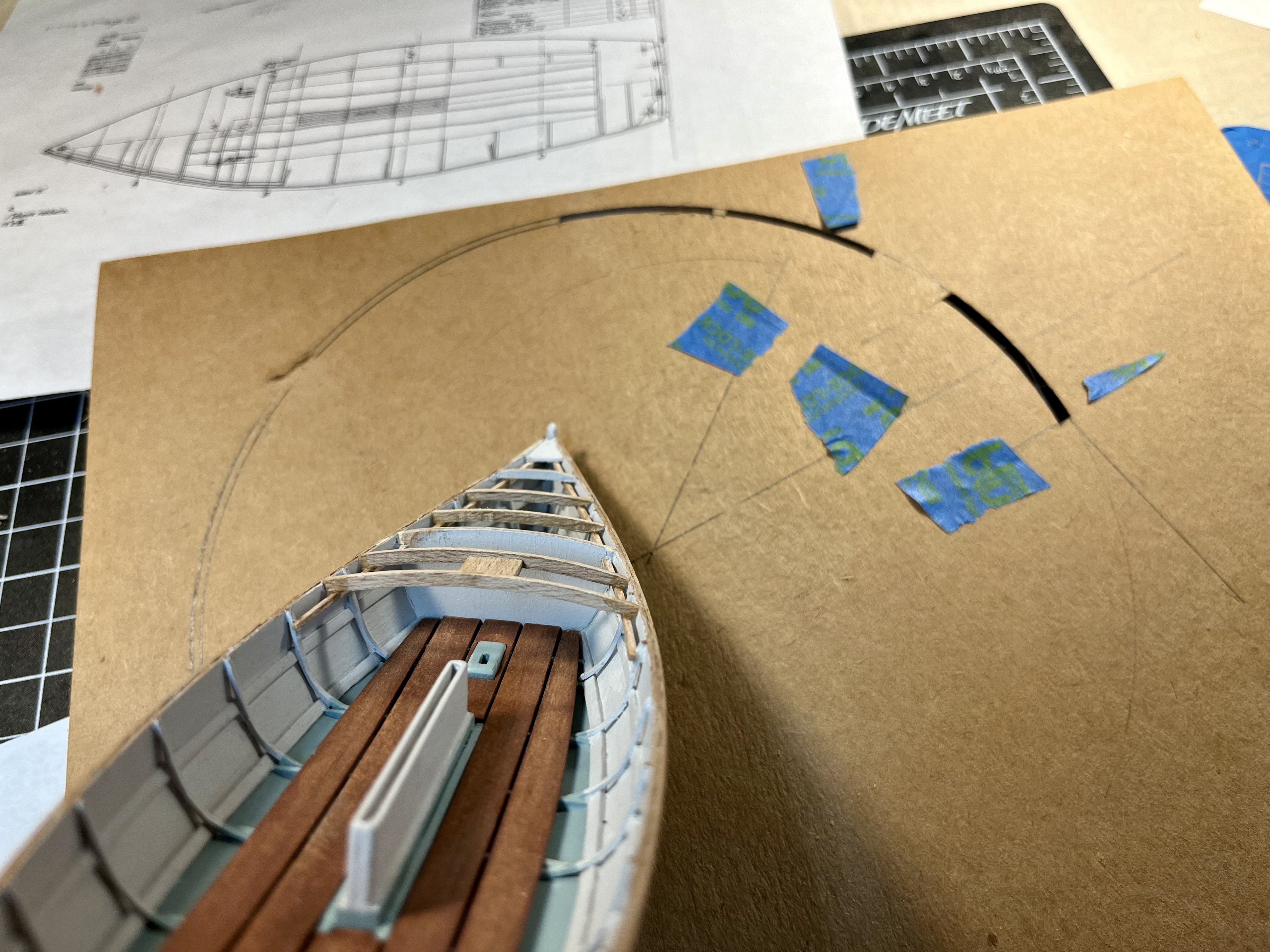
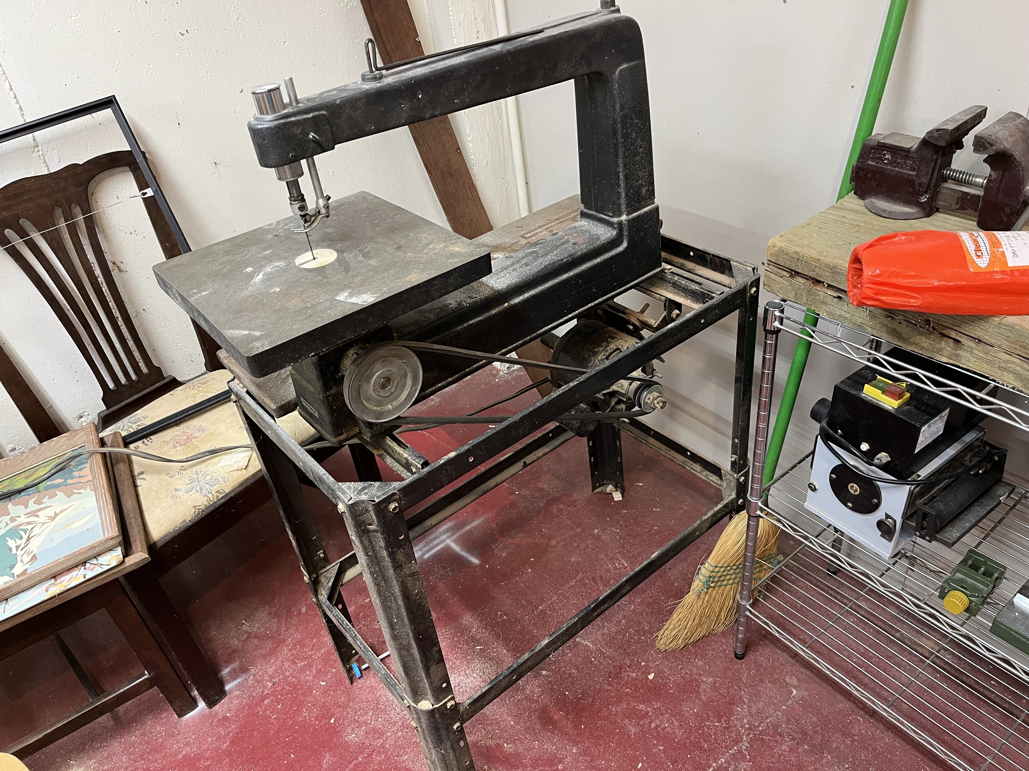
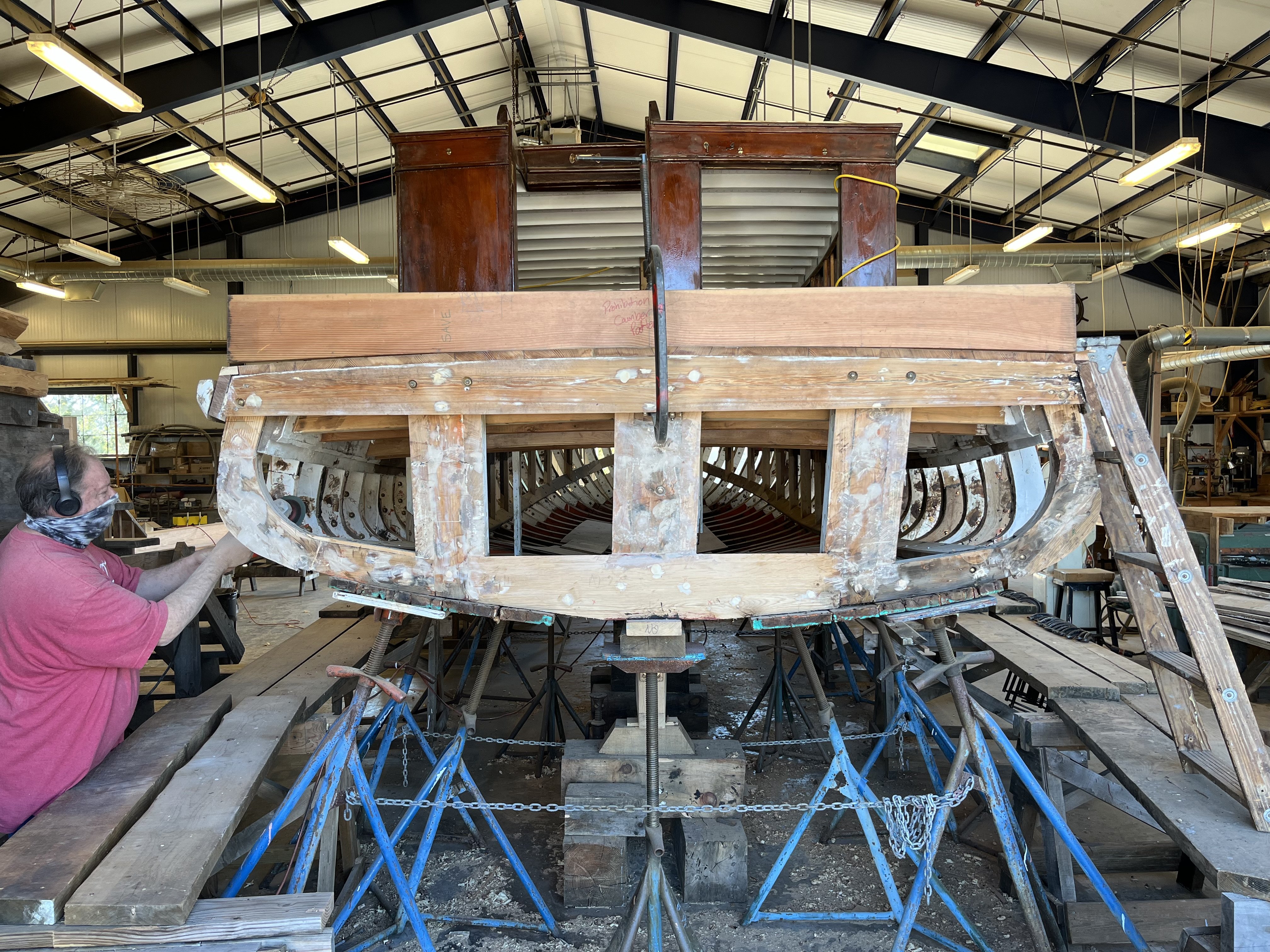
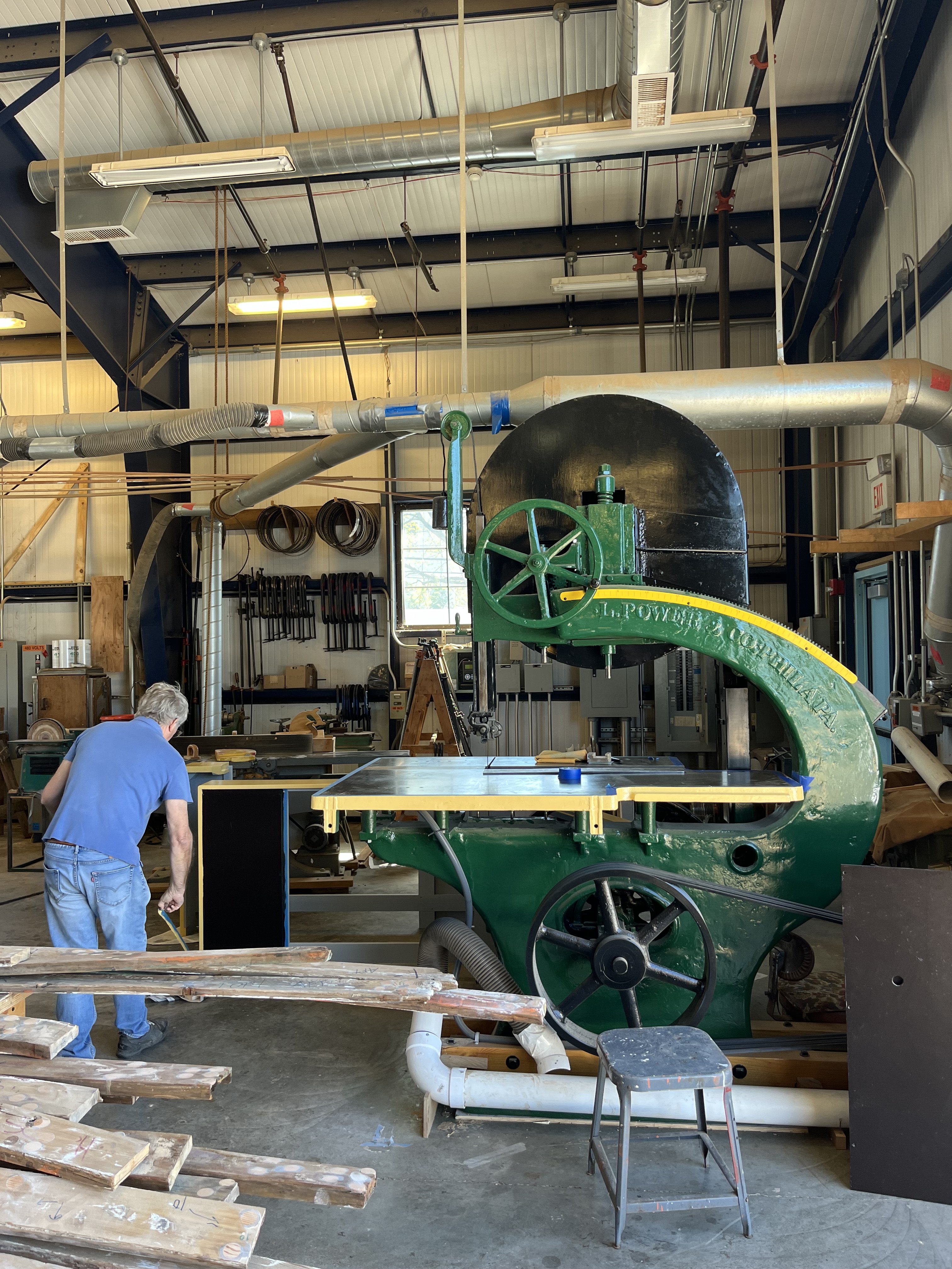
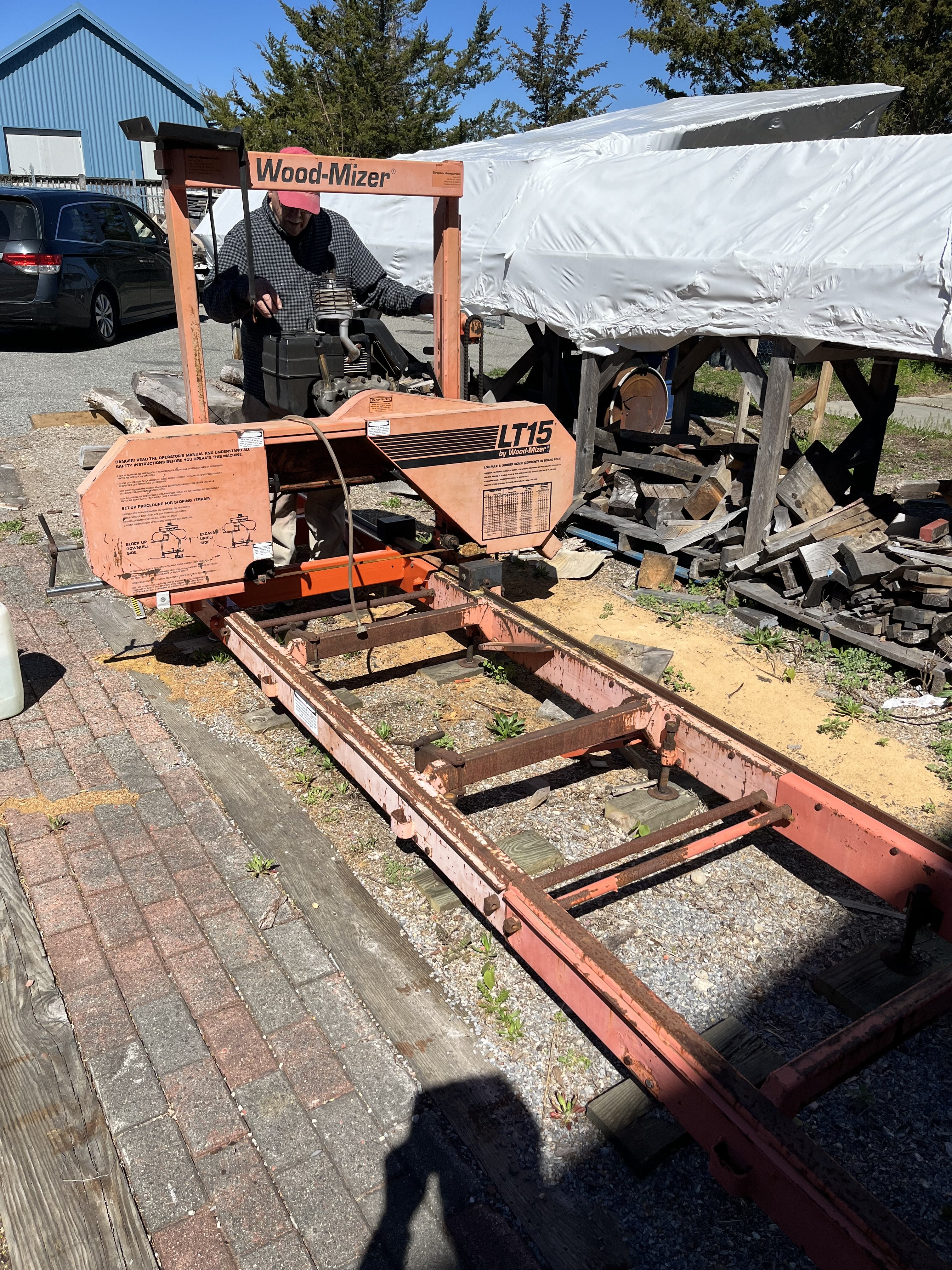
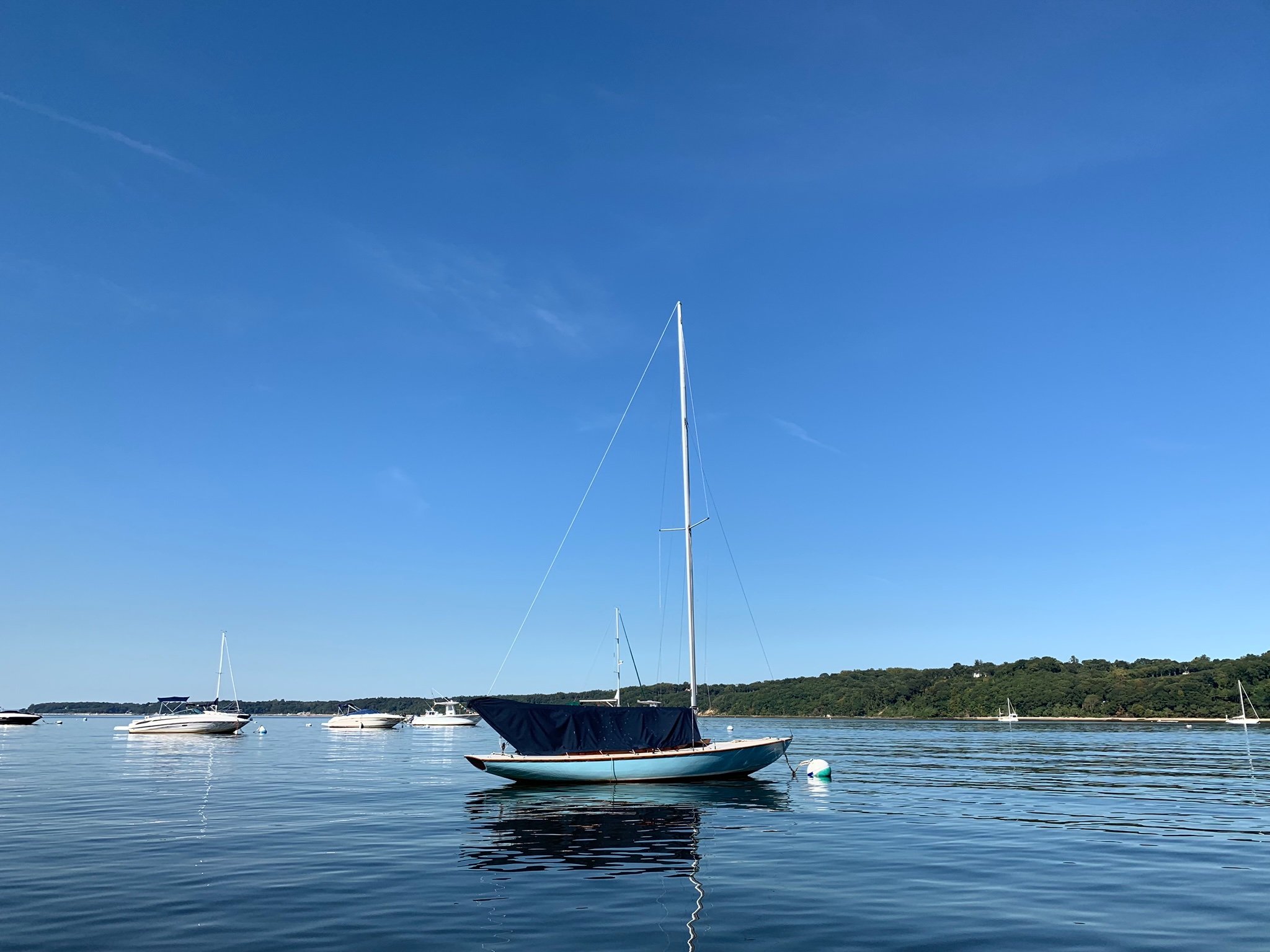
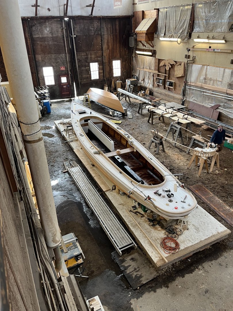
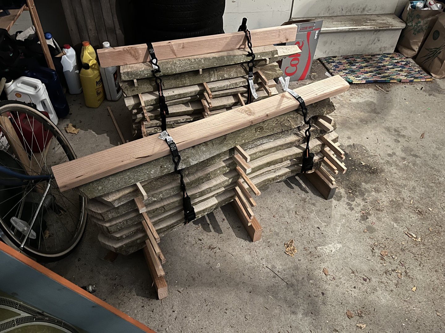
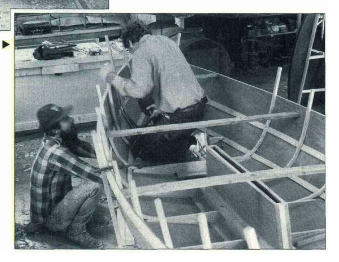
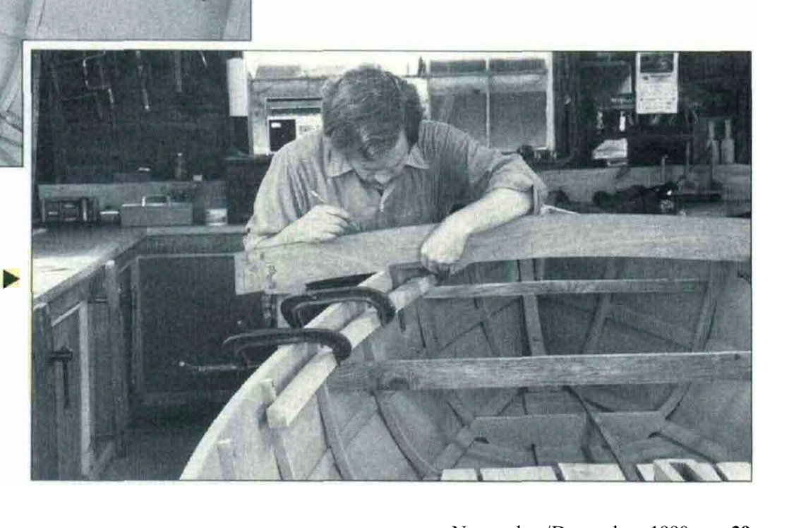
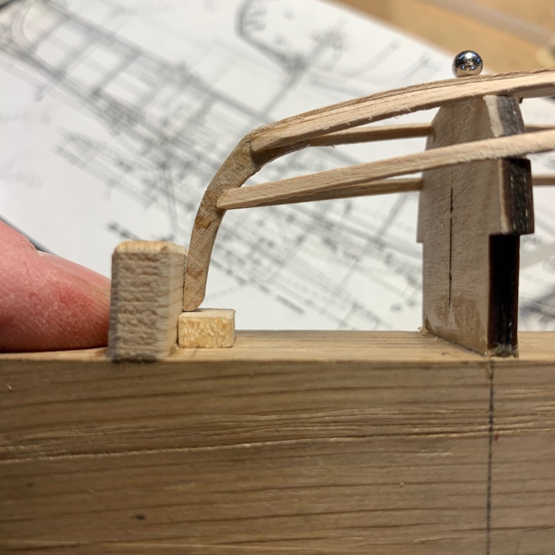
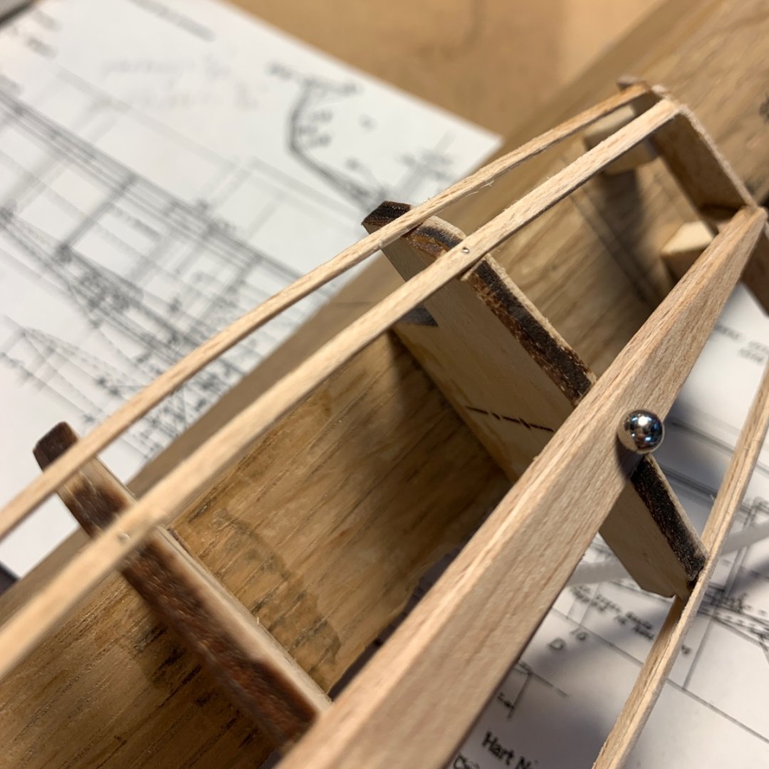
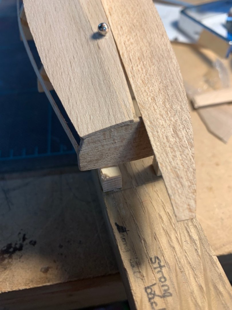
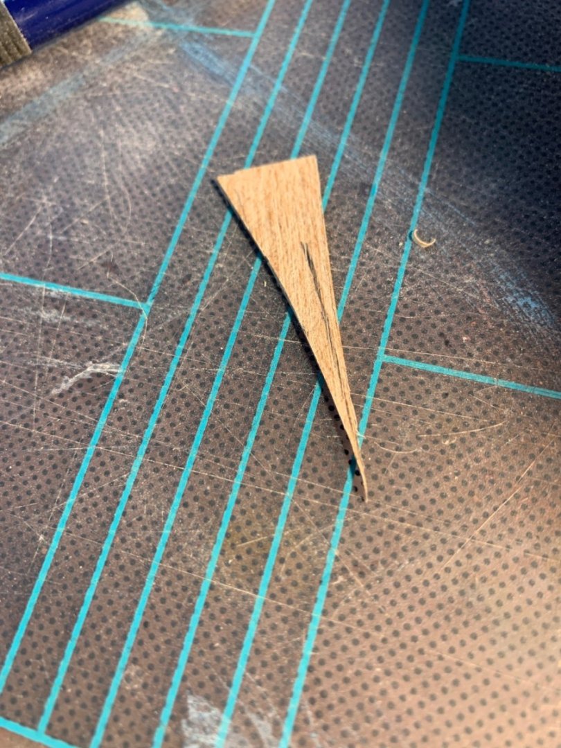
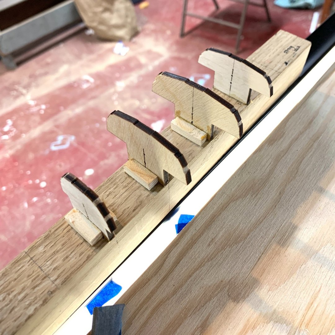
 A few more deck beams added. I got a consistent curve for the beams by drawing a pair of concentric circles with a protractor onto a piece of shirt board. The distance between the circles would be the ~thickness of the beams. I would tape pieces of timber, milled to thickness in the path of the arc - sounds like the eclipse. Put the sharp end of the protractor into the small hole in the center of the circle and draw the pair of concentric circles onto the wood. Rough cut and sand to the line. Or until the line disappears. Here’s the ship yard with RIGEL as the center of attention. You can see the pattern cut for the elbows that will support the side decks. Not shown are my Proxxon chop saw, table saw and drill press which I picked up second-hand from a man whom used them for doll houses. Also not shown are the big box brand band saw (say that 5 times fast) and drill press. Here’s the “jig saw” a neighbor gave me. It was a tool from a local high school’s wood shop. I’ve started using this more and more. I will likely put it to more use when I begin building models at 3/8 scale. What follows are a bit of a digression: some images from my recent trip from the Glen Cove area of Long Island to Newport. First are photos of a New Haven style sharpie that the preservation shipyard at Mystic Seaport has been working on for some time. It was more impressive then I imagined it would be. I always pictured that they would have a daintiness about them, given the drawings I have seen, but this boat is very substantial. The next images are from the International Yacht Restoration School in Newport. They are of the launch RESOLUTE, designed and built by the Herreshoff firm around 1916. Here’s what Maynard Bray, small craft historian has written about this design. “Five of these double-cockpit launches were built after they were designed by Nat Herreshoff for possible use by the U.S. Navy during the First World War. (Destroyer Tenders?) Legend has it that because the Herreshoffs wouldn't allow other builders the use of their design, the navy went elsewhere after obtaining only one boat. Two boats that were built to this design by the Herreshoff Manufacturing Company ended up at the Seawanhaka Corinthian Yacht Club on Long Island…” The boat is the property of the Mystic Seaport but is being restored by IRYS, likely by instructors and volunteers this summer. Finally, a few pictures from Building J in the town of Oyster Bay, LI. I was there last week to borrow their Wood Mizer to mill two large, knot free holly trunks that were part of a tree removed from the church property. They are working on a large cabin launch - with quite a sordid history - built in Alabama in the first quarter of the 20th century. The ship saw was recently restored by the some of the few professional shipwrights, and some of the many volunteers, who help in this amazing shop. Holly planks. Between 1” and 2.5”. Stickered and strapped and ready to go into a kiln this week.
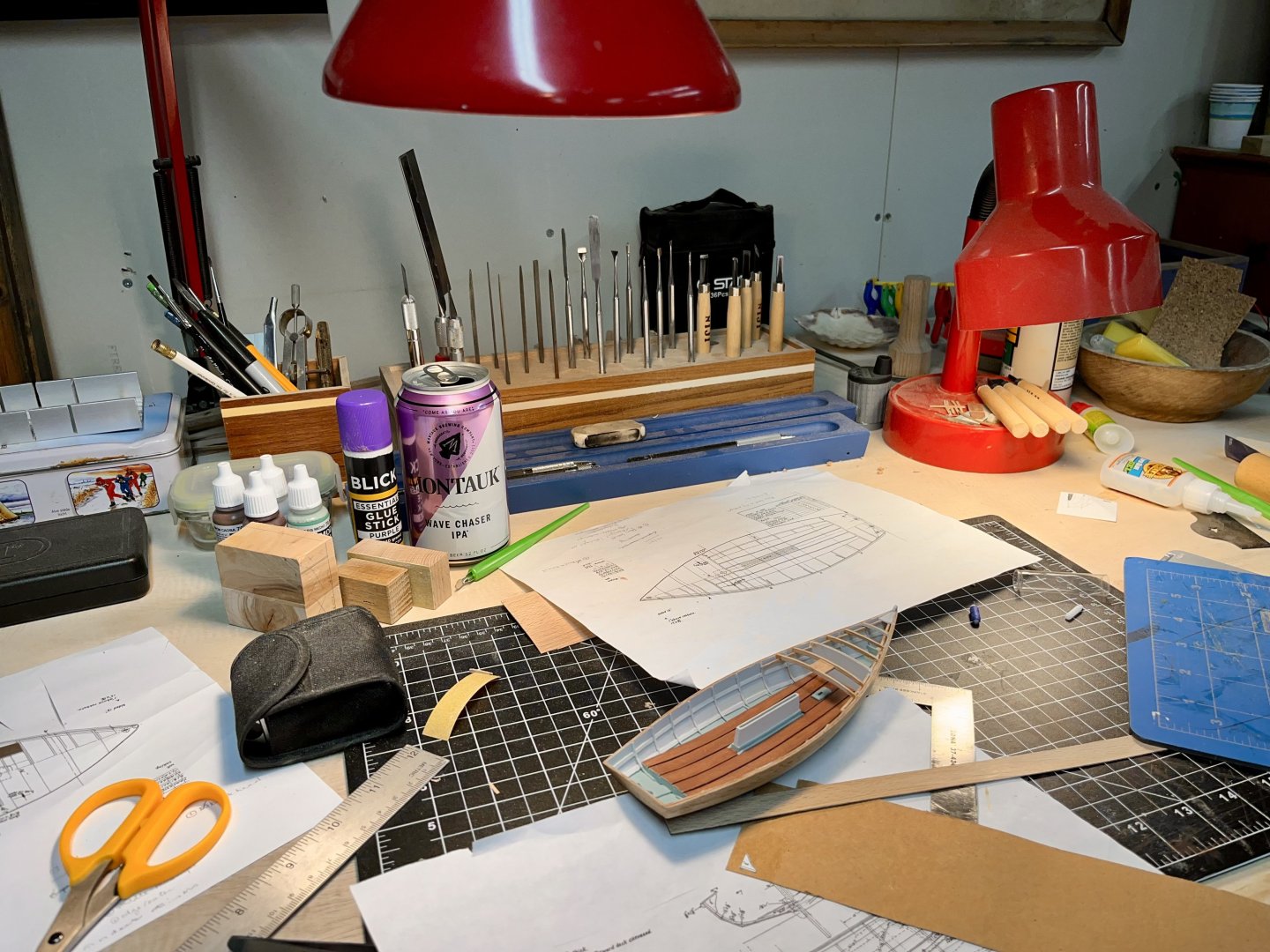


-
Hello from Long Island NY
Reverend Colonel replied to Charlie Masone's topic in New member Introductions
Charlie, are you still here? Logging on, making models? I’m a Long Islander, too. Drop me a note. -
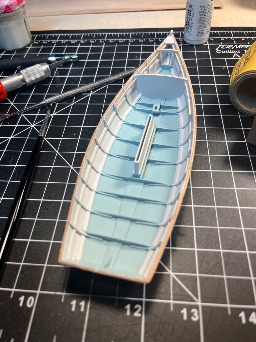
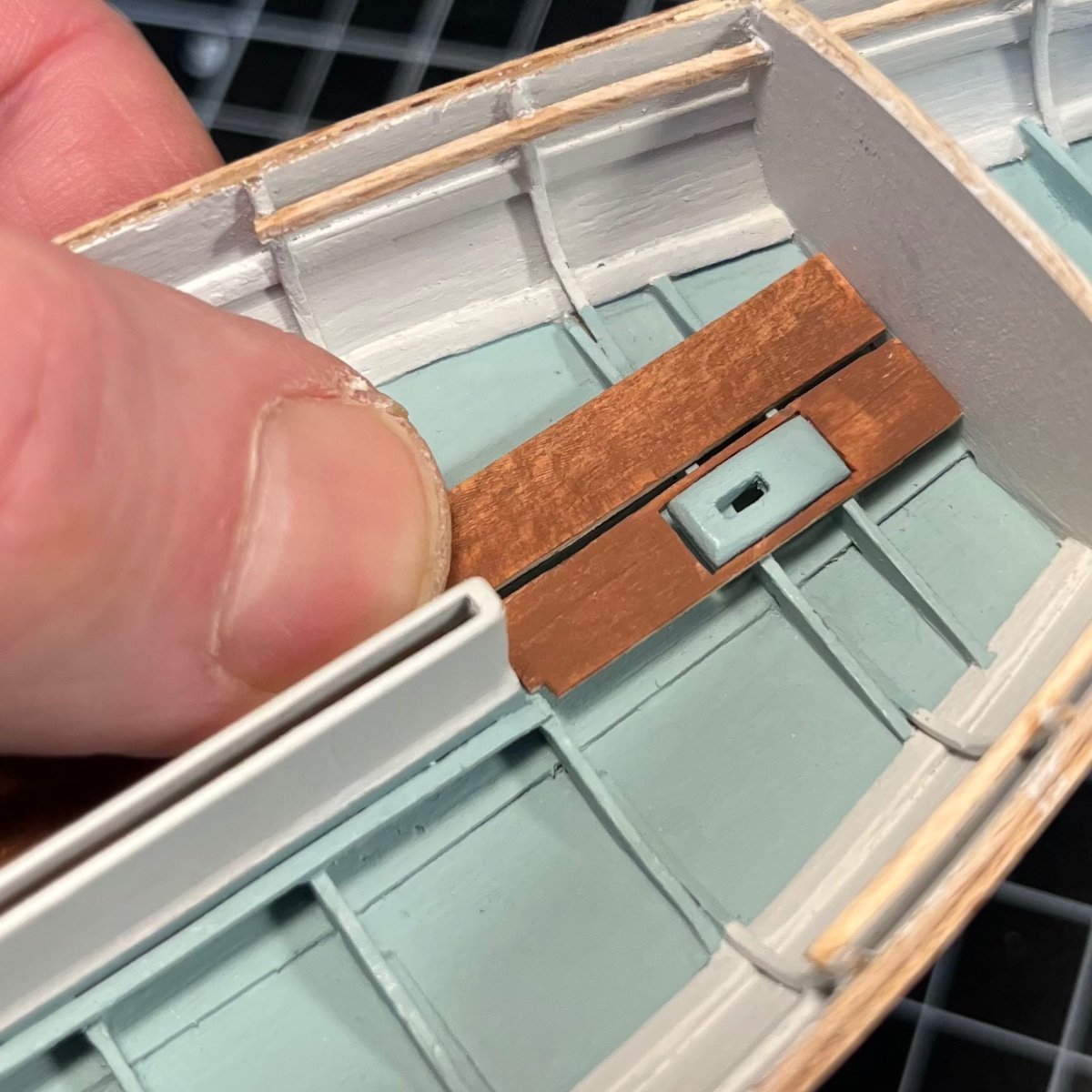
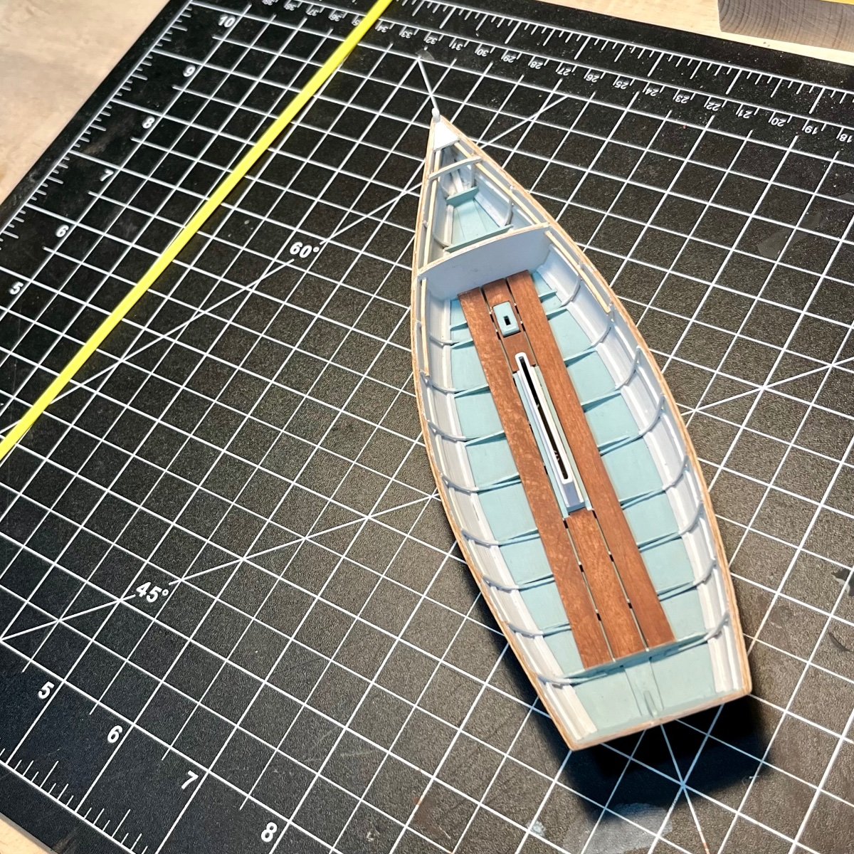
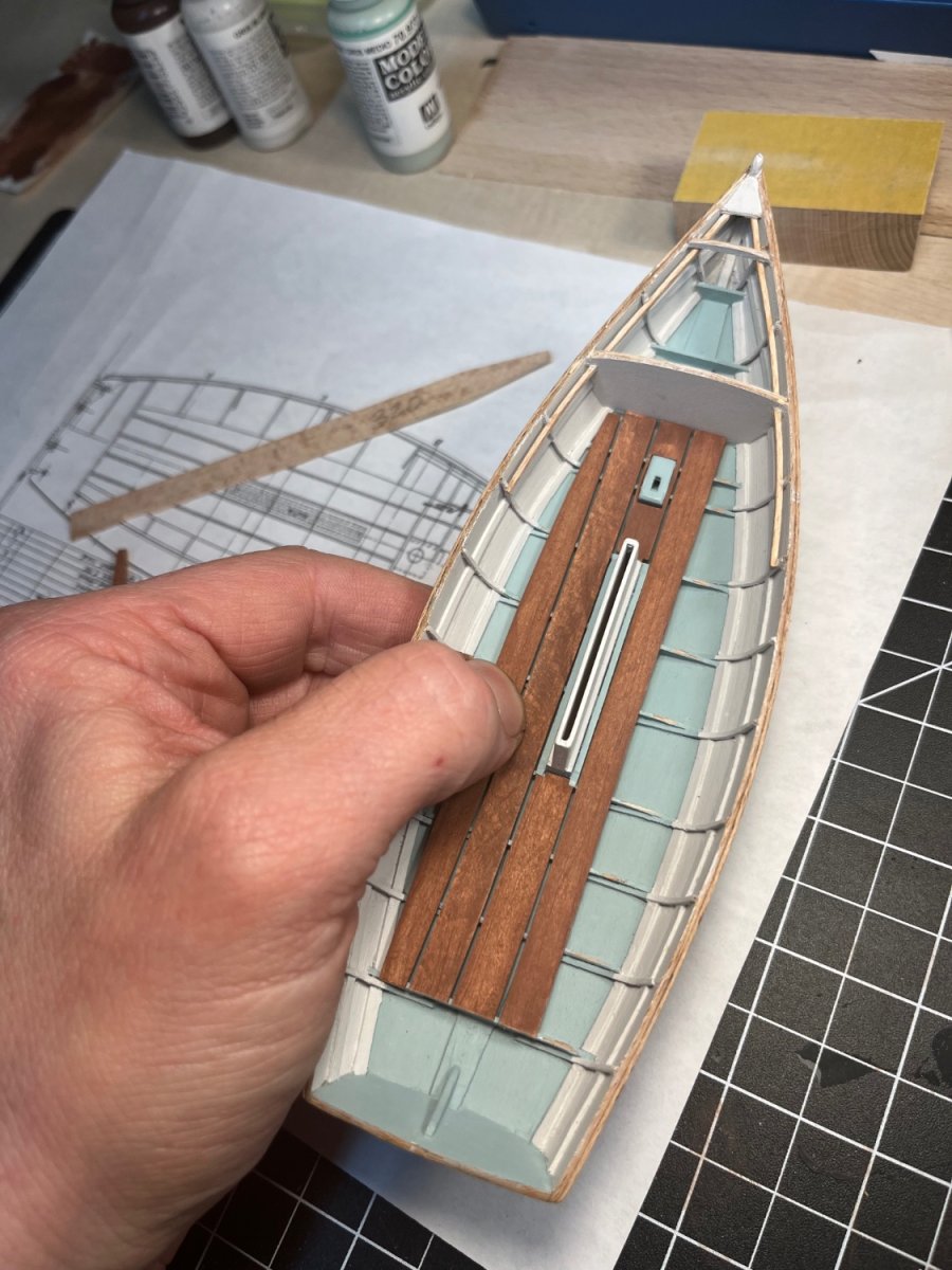
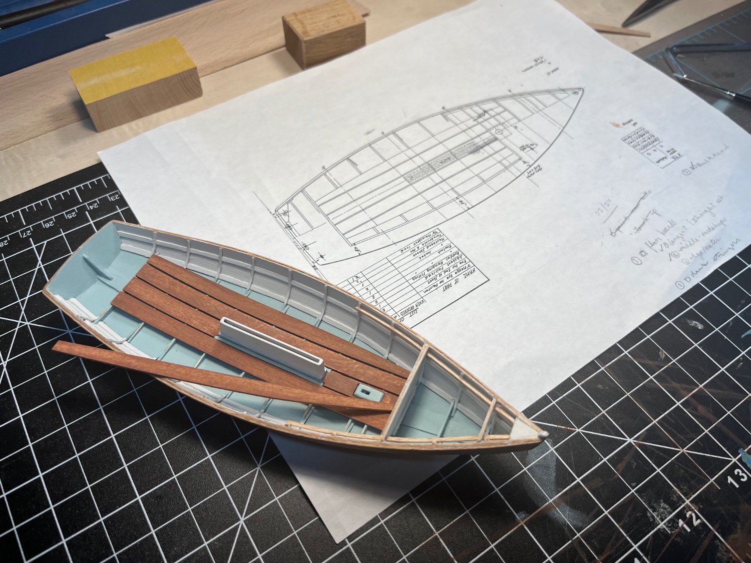
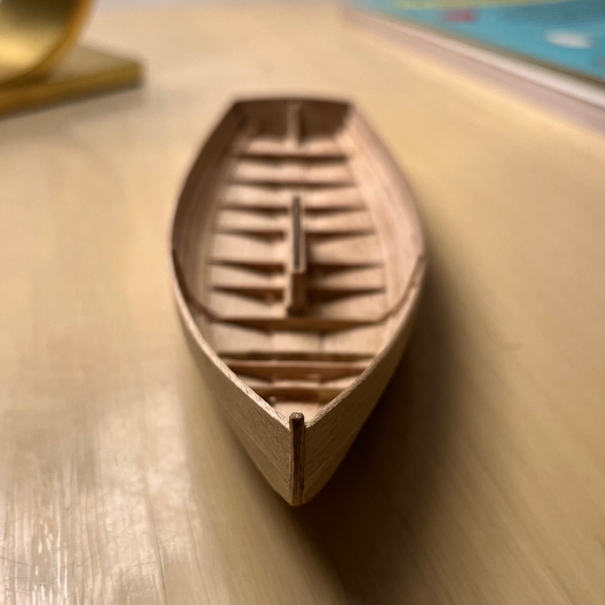
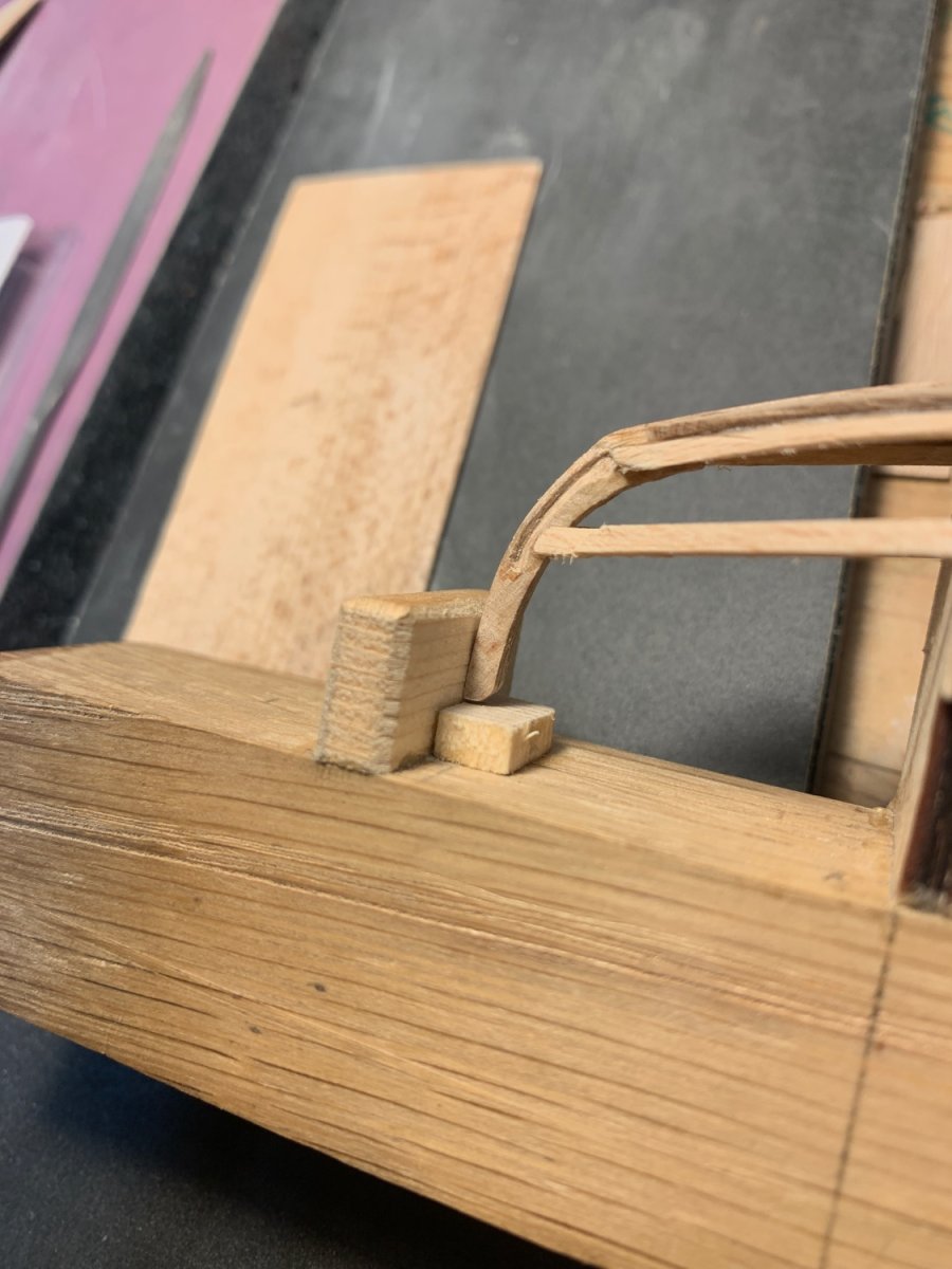
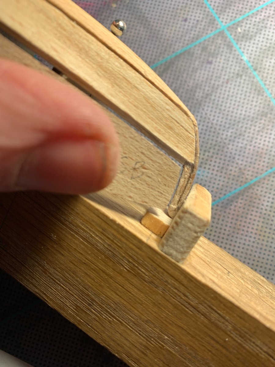
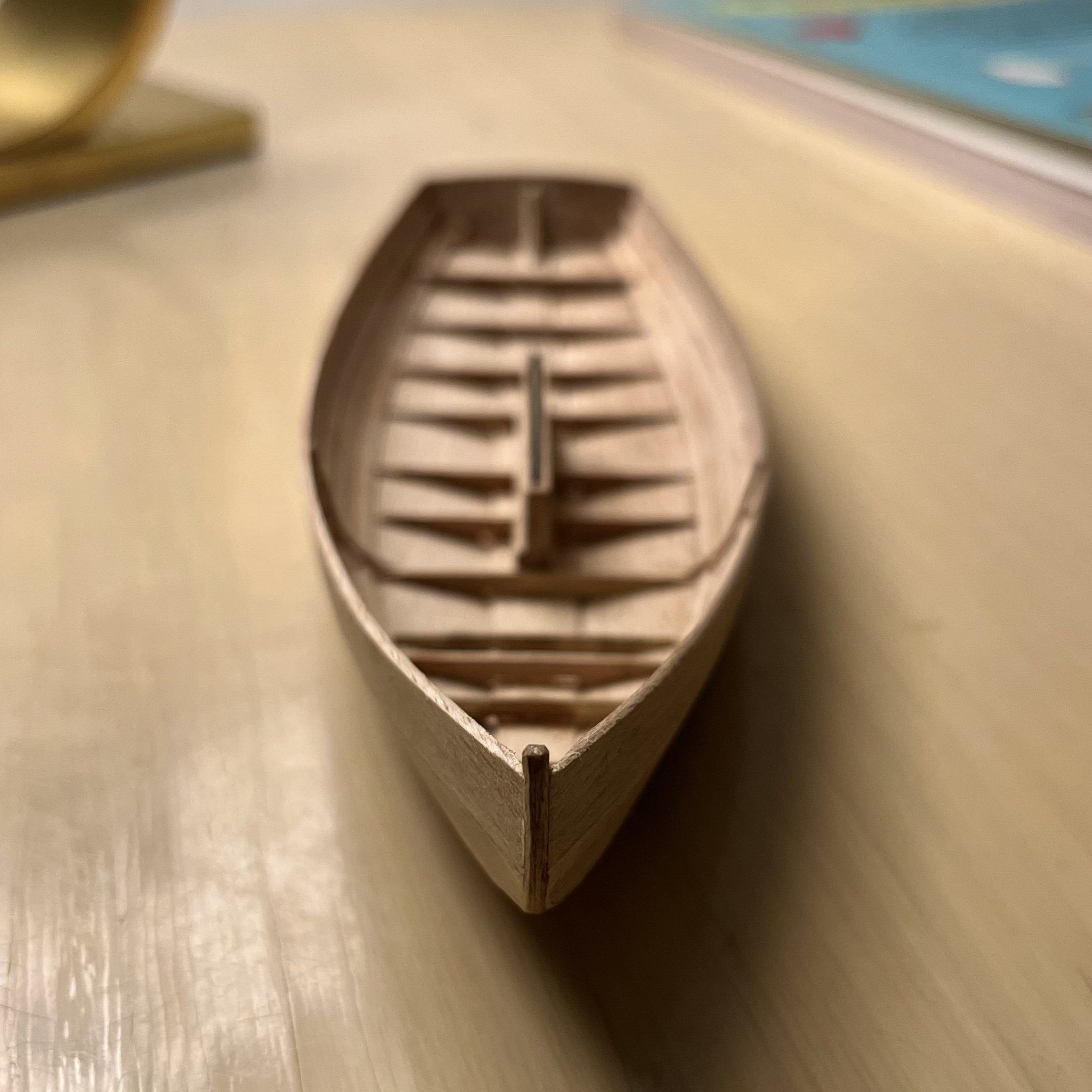
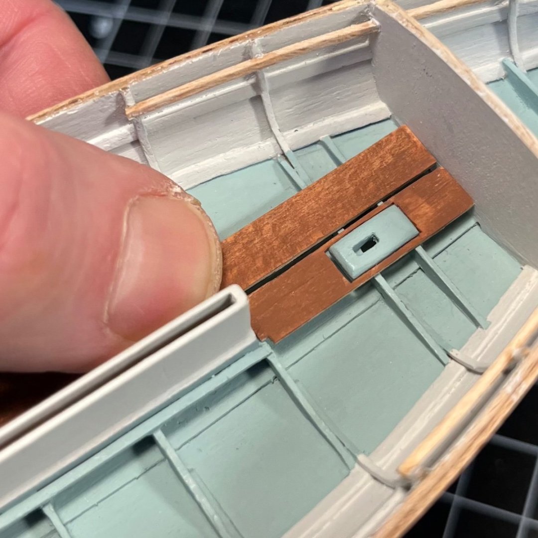
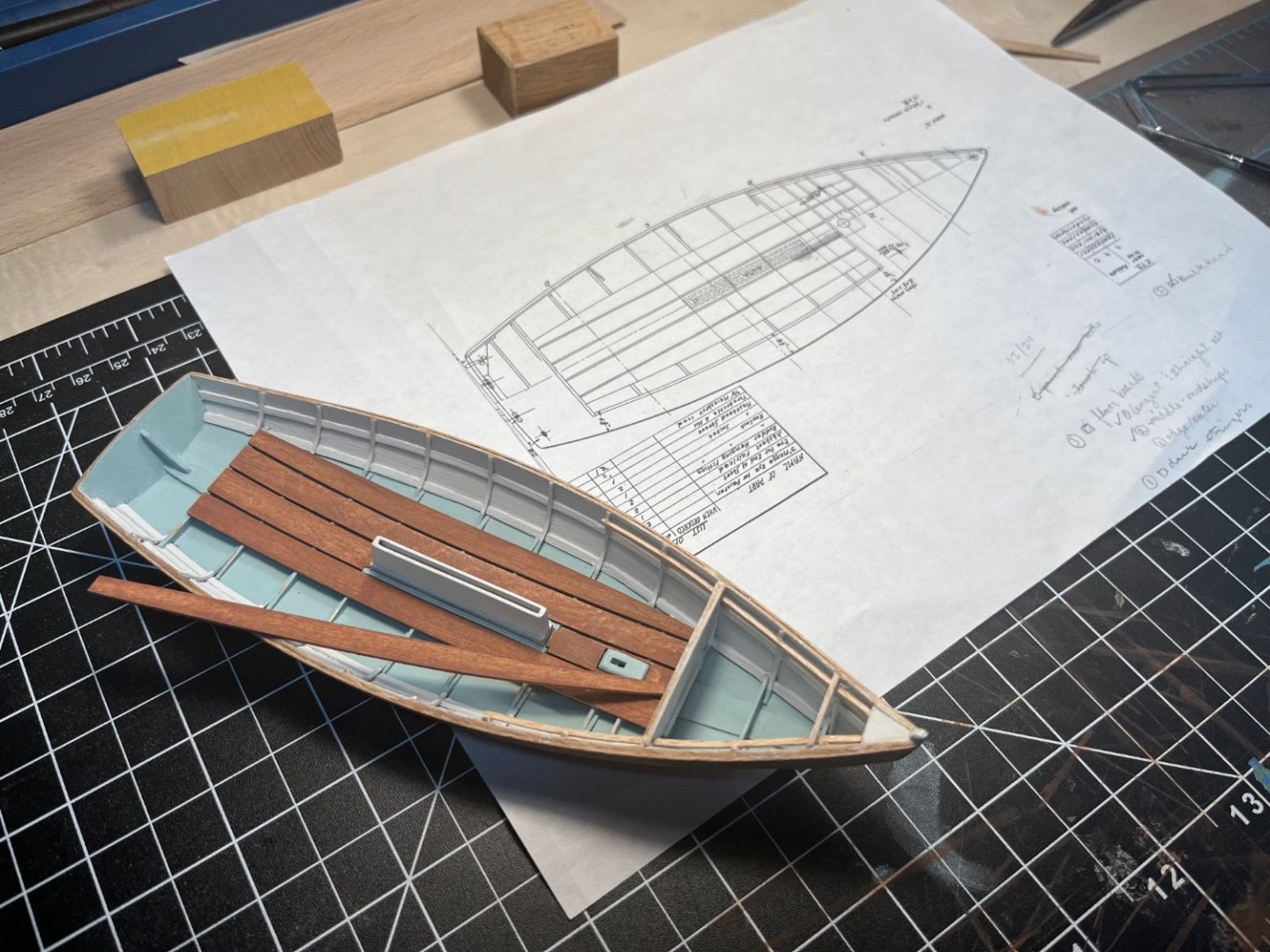
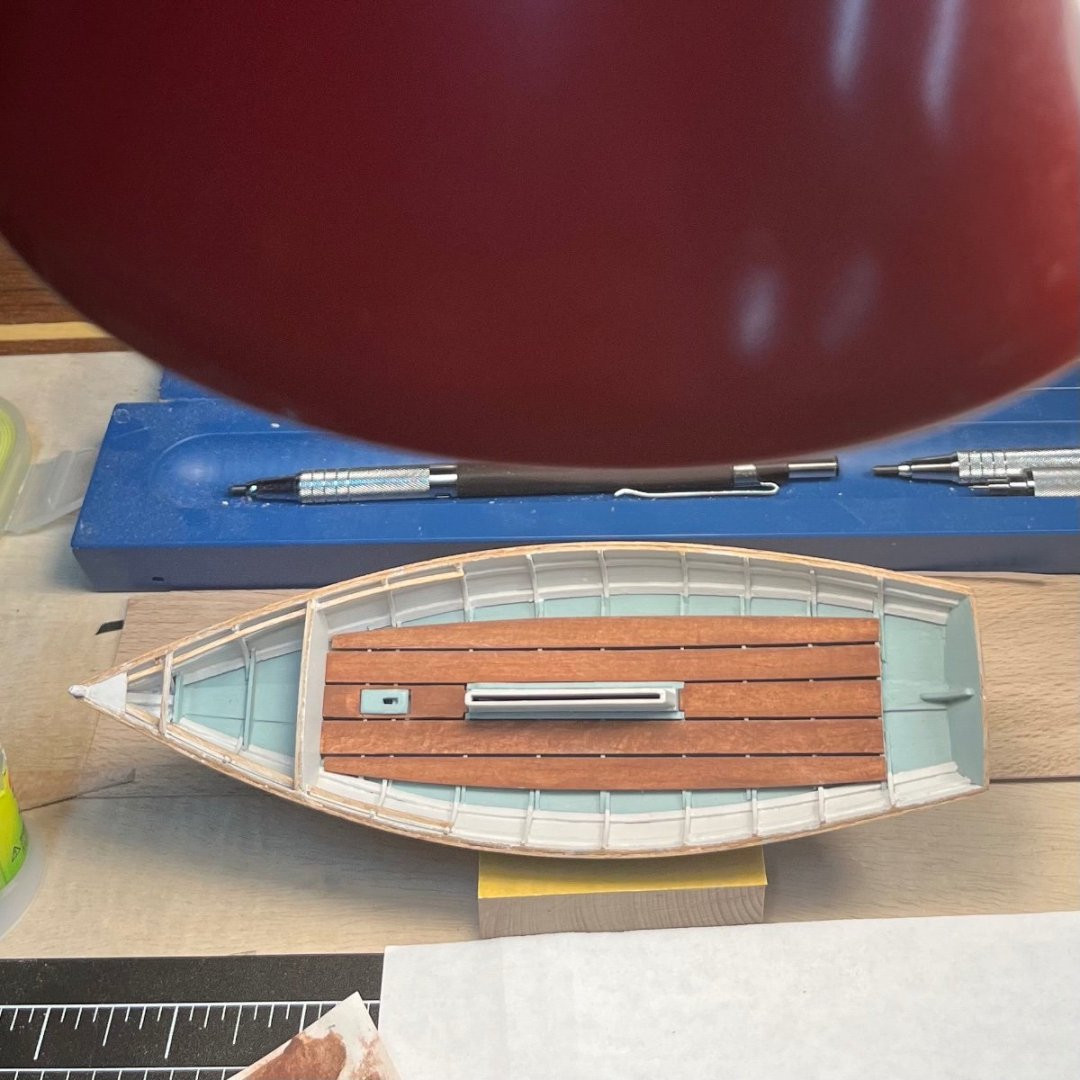
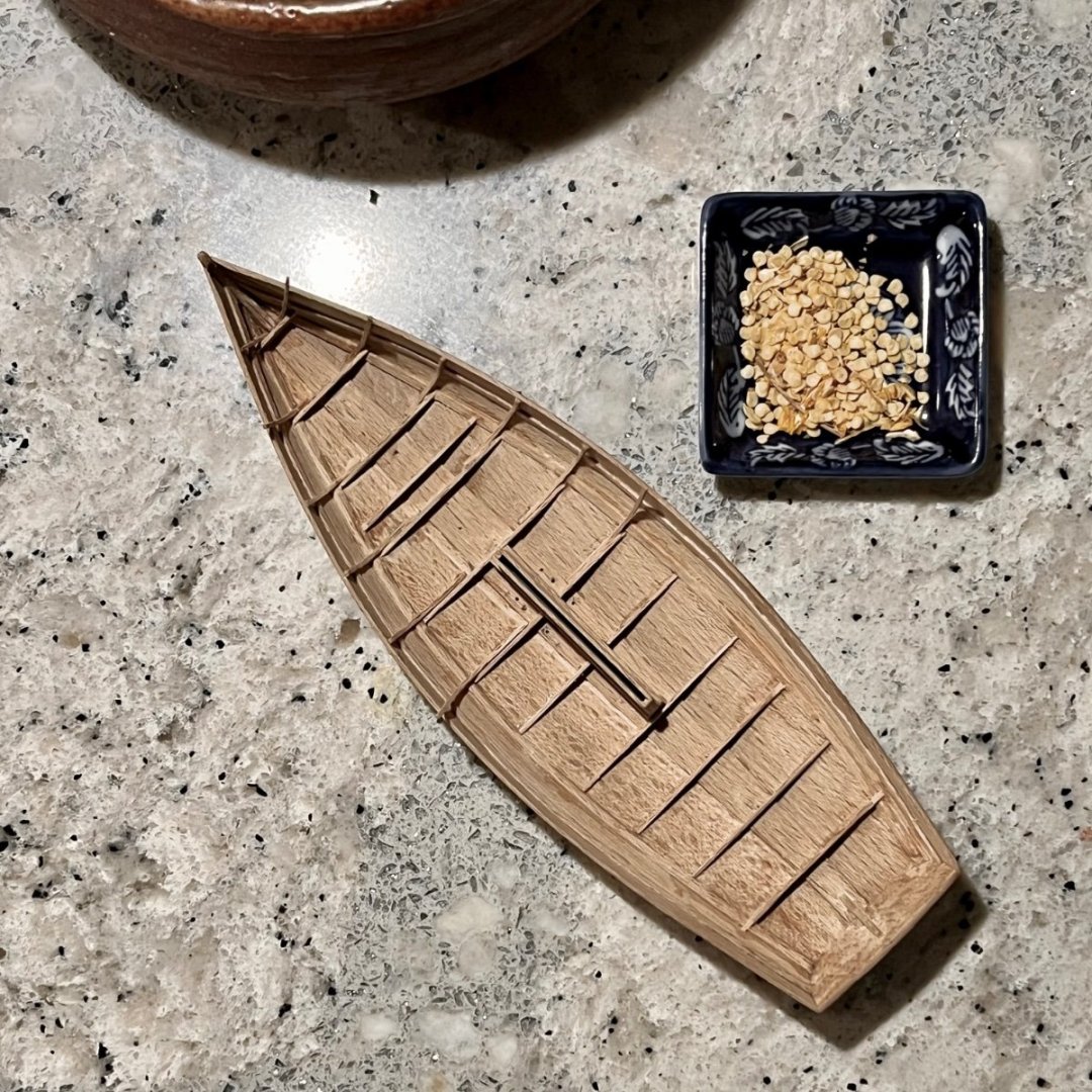
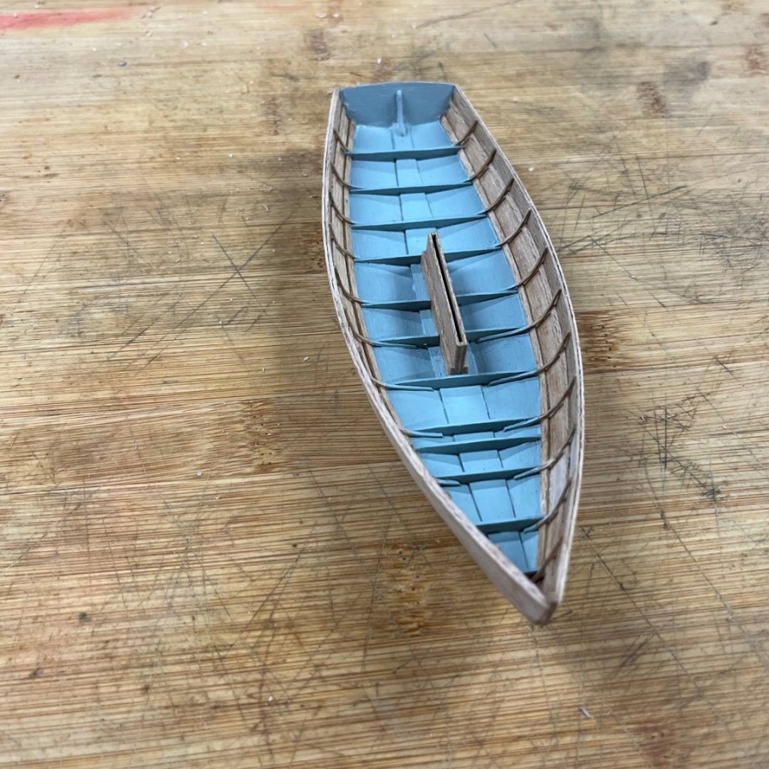
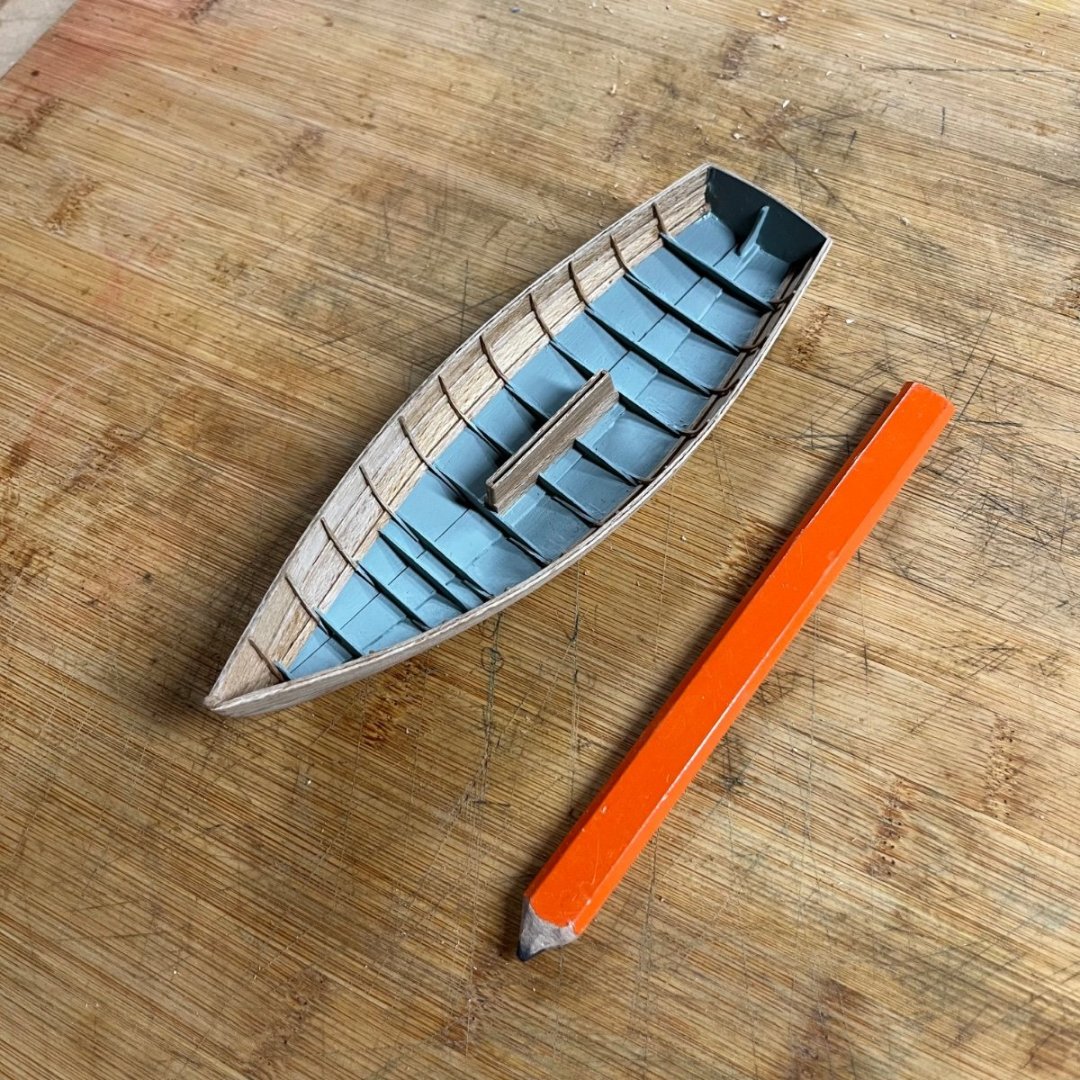
Wefalck! Yes! To all of your considerations. The three strakes, three on each side rather, creates a shape that appears from many angles to be round. It also makes for a light, strong boat that is relatively inexpensive and easy to build. It should also be a great sailer. The “stringers” are called chine logs. Stringers (for deck beams to rest on), two deck beams, the watertight bulkhead and the breasthook installed and painted. The mast step is also installed. Note beams on either side of the center board trunk. Sole planks being dry fit. The hole in center plank that allows it lay over the mast step was marked and made by drilling out most of the wood and using small chisels to make it square. Center planks (fore and aft) and the straight planks installed. Dry fitting outboard sole plank. Sole planks installed. I painted the beech wood planks with two washes of mahogany color paint by Vallejo. Remaining deck beams, elbows for the side decks, aft deck beams, chain plates up next. Have a nice day!


-
Andy. I did get the plank bender and it helped a lot. The thing that’s keeping the frames from touching the planks between the stringers is that said stringers are too big, not to scale. At that point in the build it was not easy to cut consistent size stringers in the beech. I suppose I could have sanded the stringers down after installed until frames came into contact. Another in a long list of lessons learned. I have loved watching your builds come together, by the way. And that you and Allan and Welfack are paying attention is a real treat. I follow your all’s posts and they have proved a great reference for me. Thank you.
-
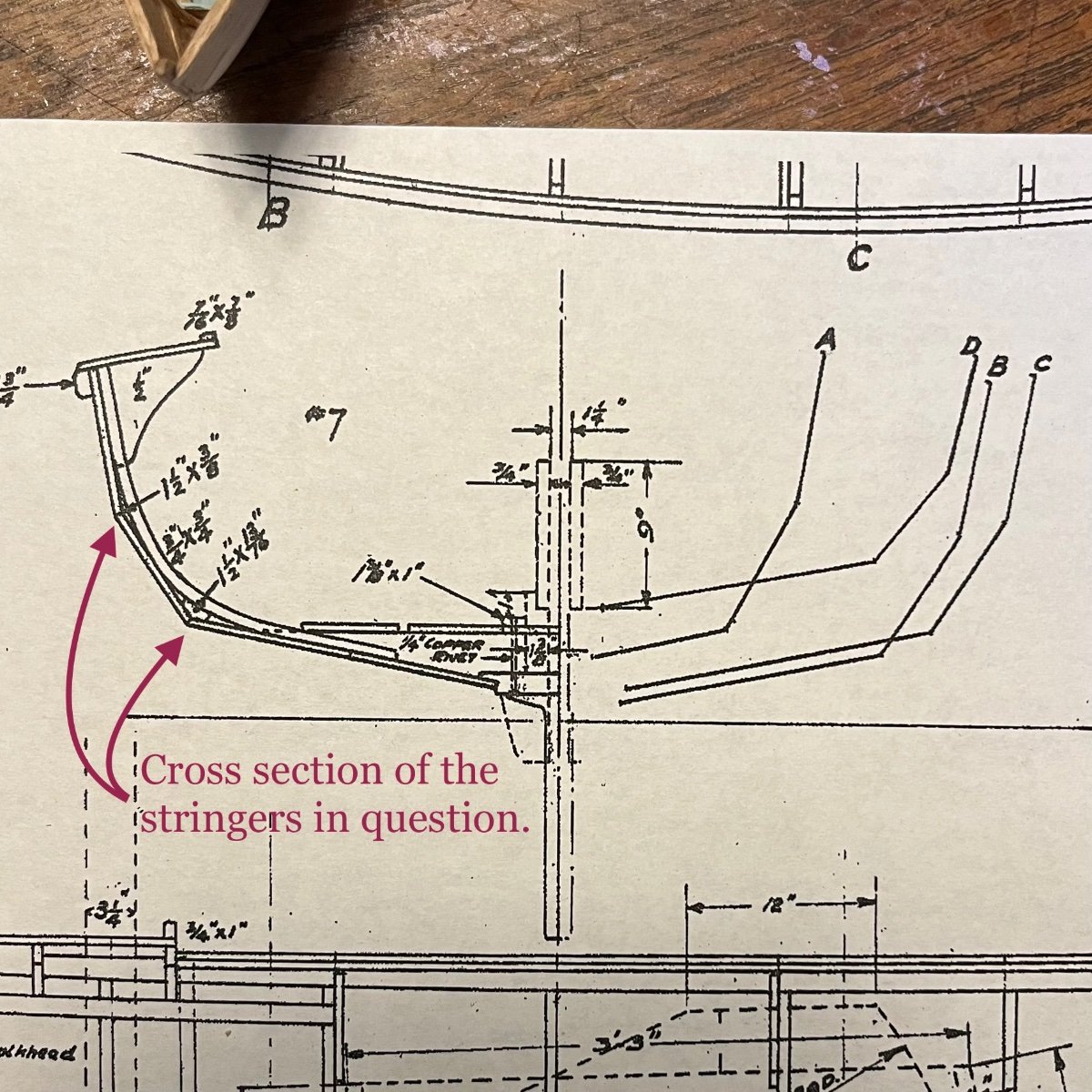
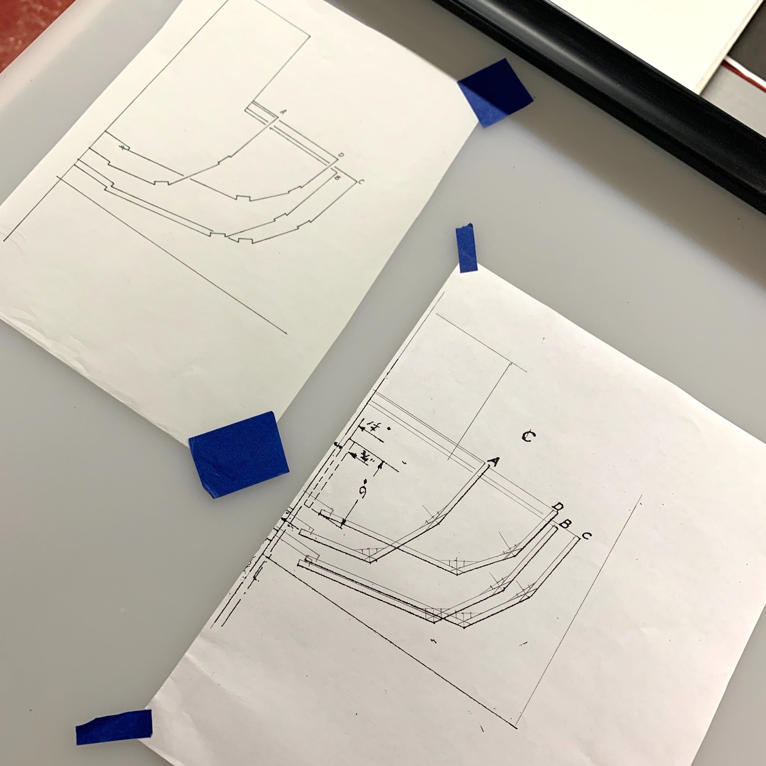
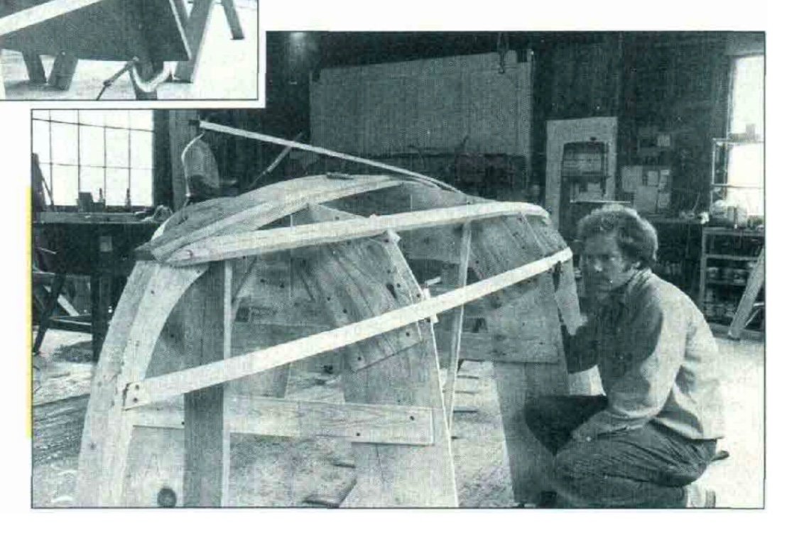
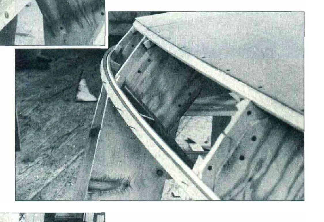
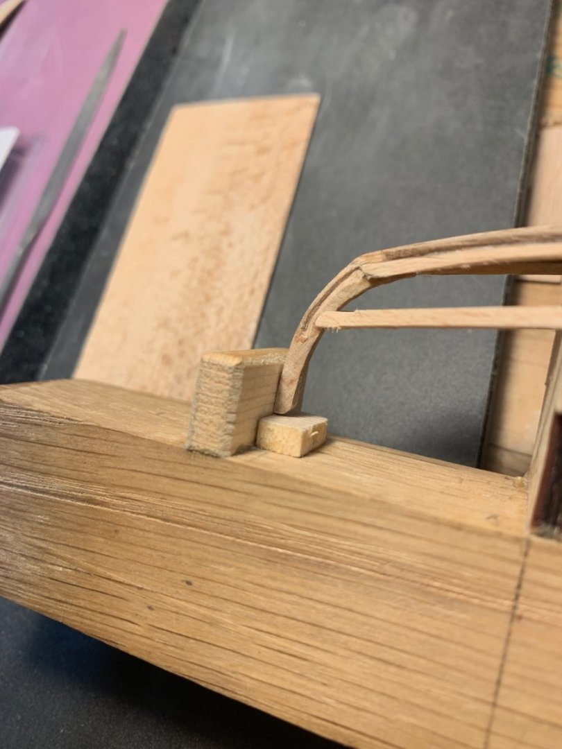
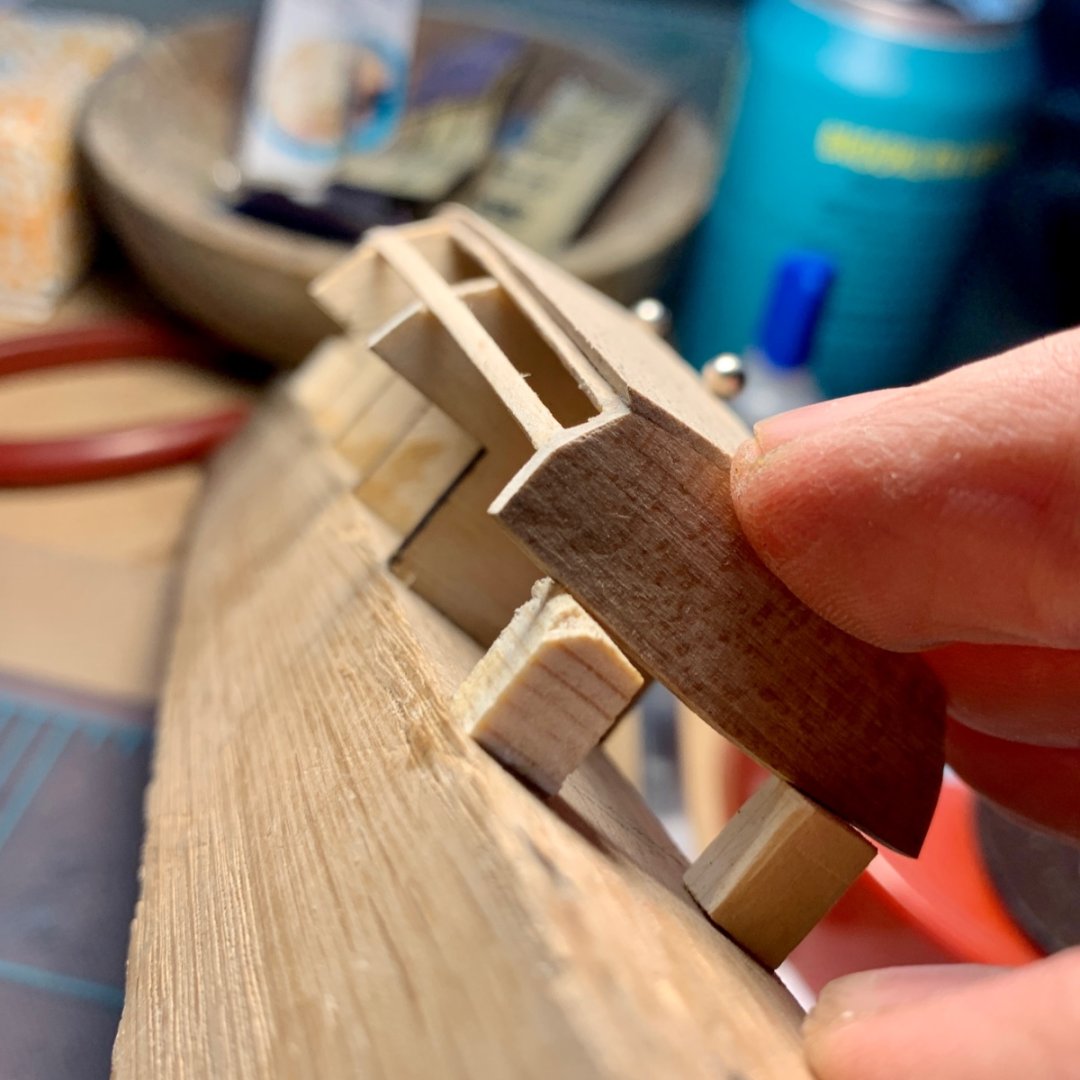
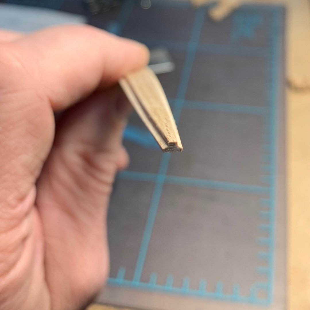
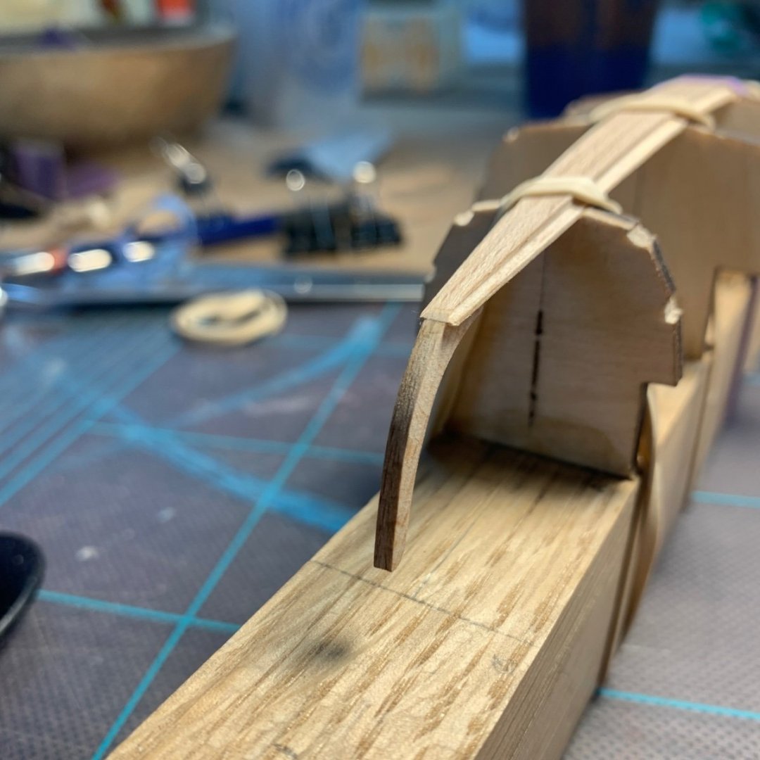
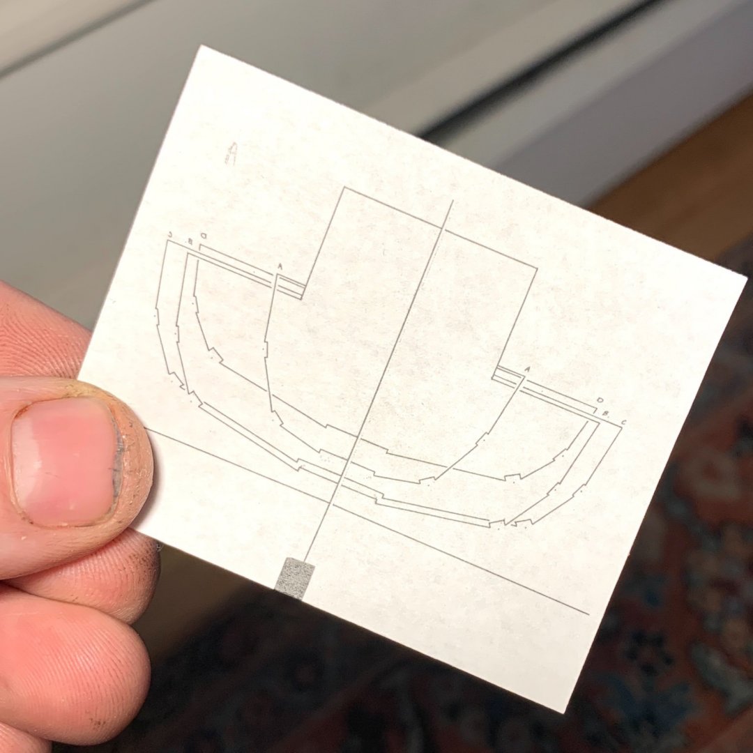
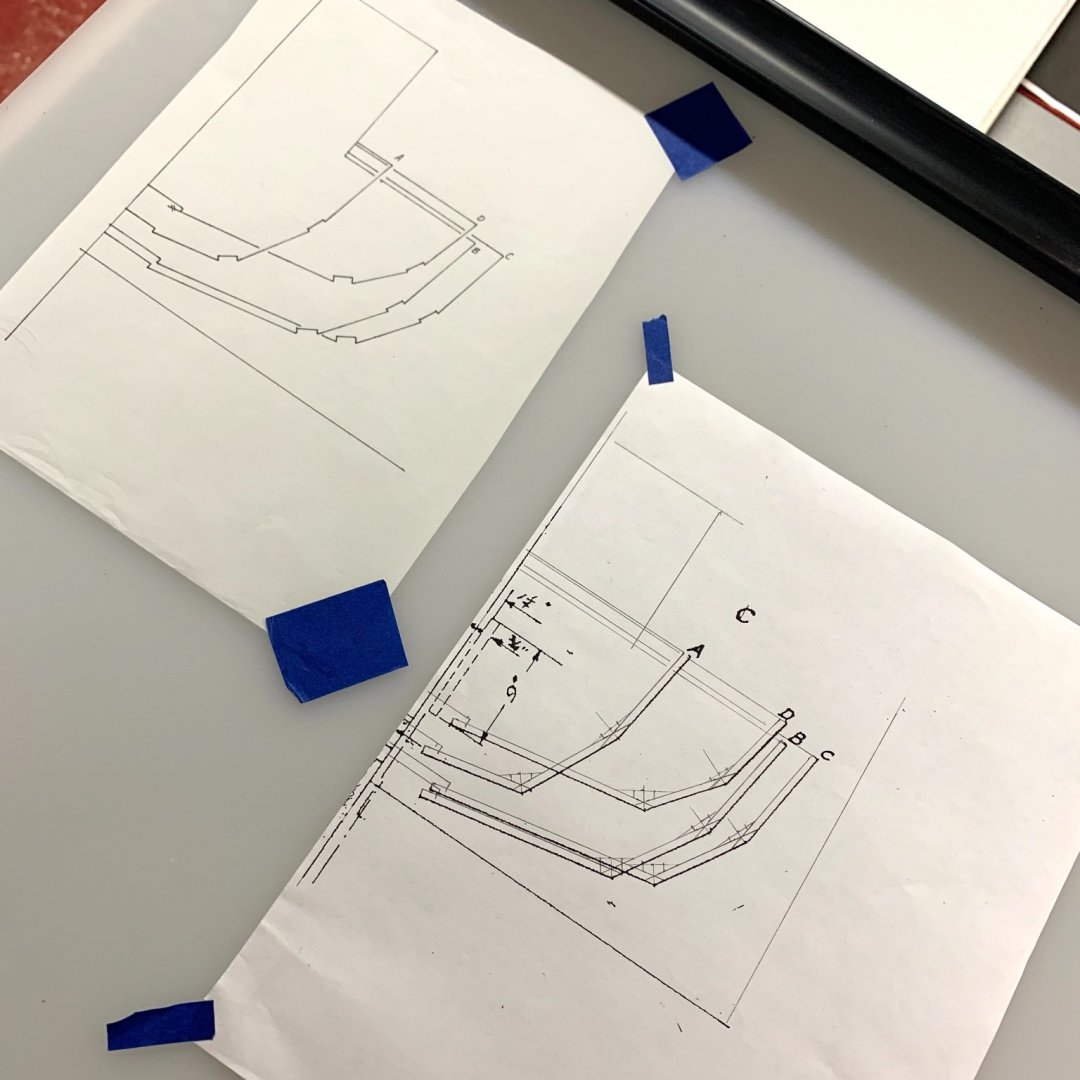
Happy to address the questions and hopefully settle this bit of the thread and with an image from the construction plans and some photos from a three part piece in Wooden Boat magazine that featured the construction of the Biscayne Bay. That the construction process was demonstrated in a magazine is one of the reasons I chose to build this boat. Very helpful for a first time modeler. I think you’ll agree that my construction process is correct, according to plans and example, even if it is not well executed. There is certainly no shortage of opportunities to improve in this craft. Fairing the stringers. How the planks attach to the stringers. Bending in the frames. Making the deck beams that rest on an inboard stringer. Jesse

-
Welfack and Allan: Re: stringers. I’ll guess I’ll have to take it all apart…just kidding. These first stringers are on the inside in the case of this build. The molds (both in the building of a full size boat and this one) are made with slots for these stringers. The planks meet at these stringers. The frames should be touching both the stringer and the plank. The stringers are not to scale. They’re a little wide and made before I had tools to get accuracy so the frames miss the planks. Trust me. It’s not the only discrepancy. But if you look closely enough, you’ll find ‘em. The photo your referencing shows the profile and the stringers are referenced by the chine line. I’ll post the lines drawing that shows the arrangement at some point. Additional stringers will be added from the stem to frame 5 to support the deck structure. Knees for the side and aft decks. Peace, Jesse
-
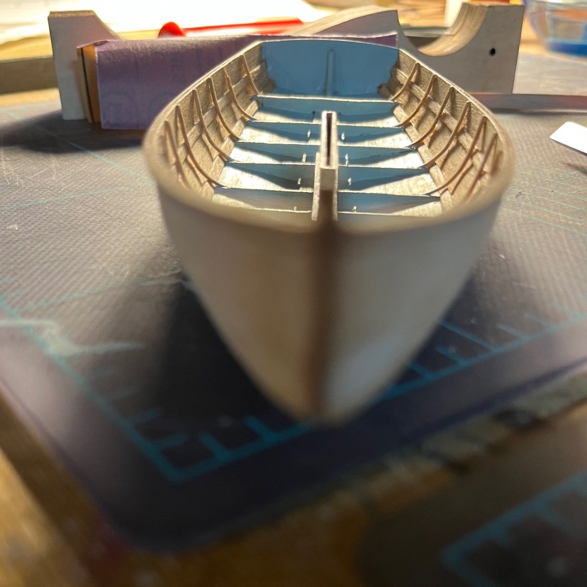
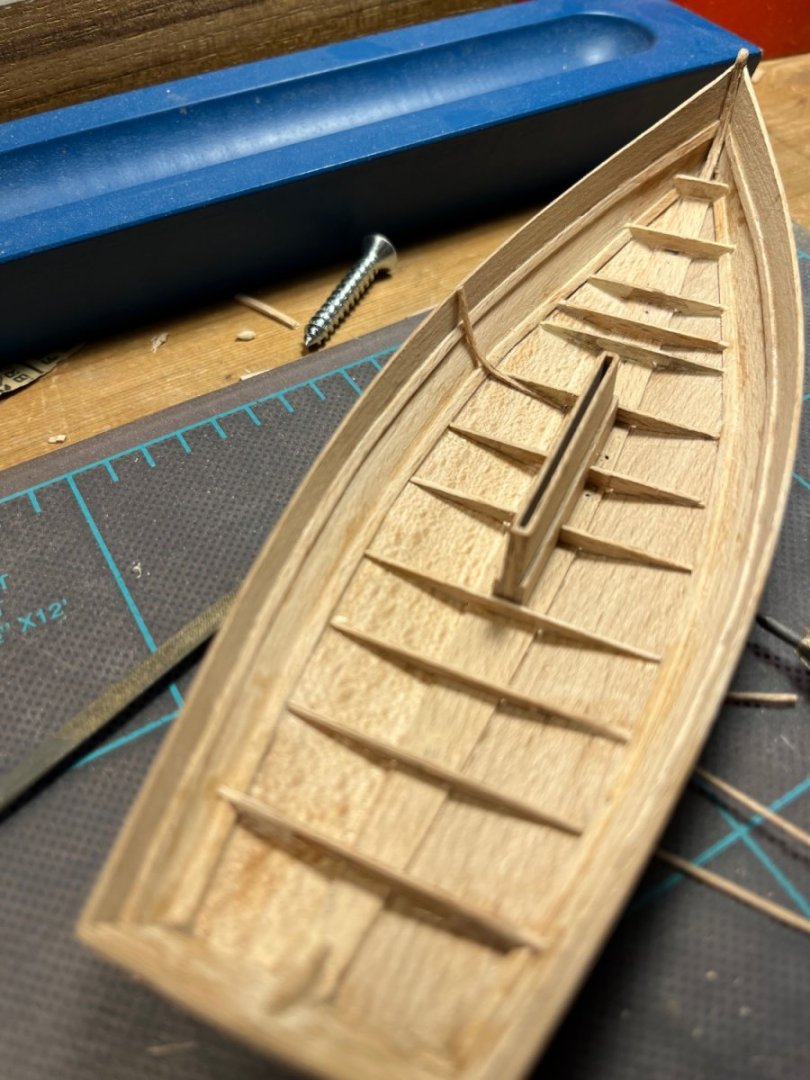
10 Months later… I’ll post some pics here and try to remember some of the details from the last several months. Tonight I walked away from the bench with every frame in. And the bilge painted grey. This part of the model will never really be seen so I figured that was a good place to start. More on that. These two photos were the first ones taken after bending in some frames. That was frustrating. The first ones I put in were done by soaking as the curves were the most gentle. Frames with sharper bends proved challenging. I got myself an electric plank bender and that changed the game. In a couple of days I breezed through the lot. Actually, before I ordered the bender I put a couple of the frames in by soaking them and bending them over the brass tip of a hot glue gun. That proved that the bender could be a worth while investment. I used CA to put them in. Next time I’ll use PVA/Titebond. Smudged superglue is hard to remove and did effect the way the bilge looked after the first coat of paint. The little traces, bumps, fillets and smears of CA became visible. I used a sanding sealer on the inside of the hull. I won’t do that again either. Too hard to sand between the frames, besides, beechwood is not porous enough to warrant the Sanding Sealer. I did use system three wood putty As filler in a few places. It was helpful to getting the limber holes as best I could. Anyway. I’ve got to call it a night. I wanna finish the crossword before bed . See you next time!


-
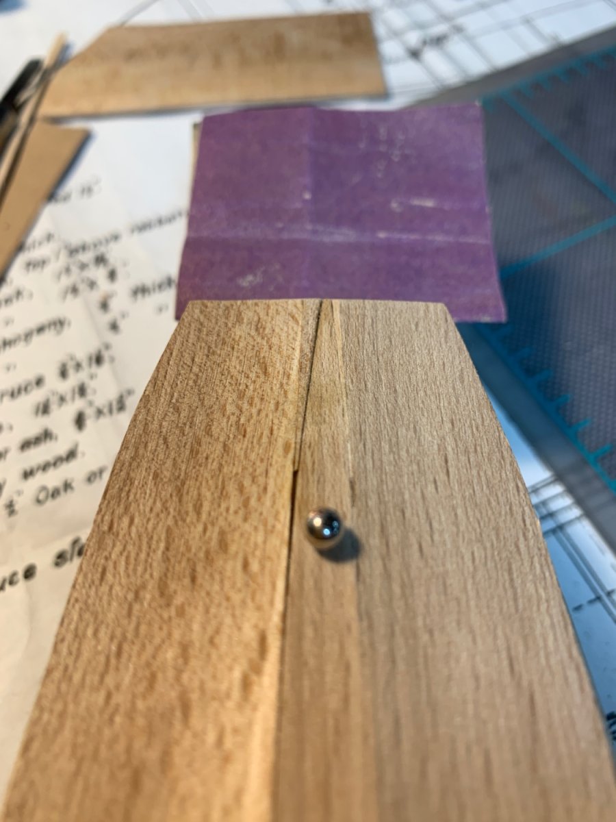
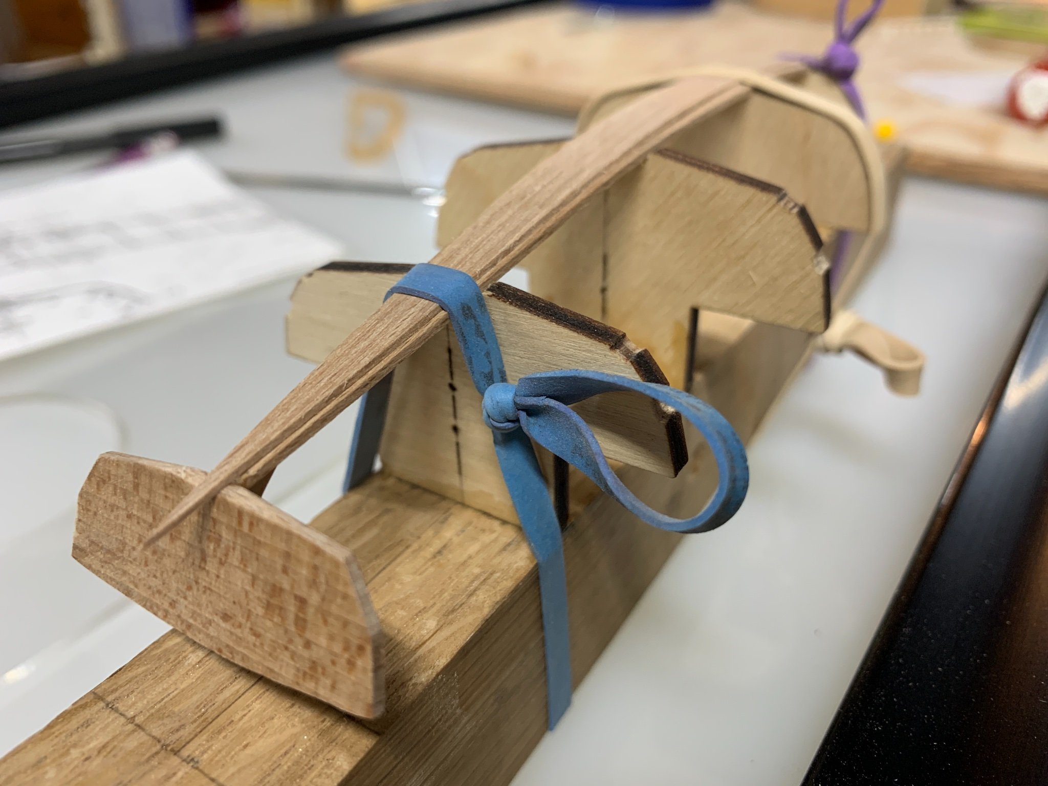
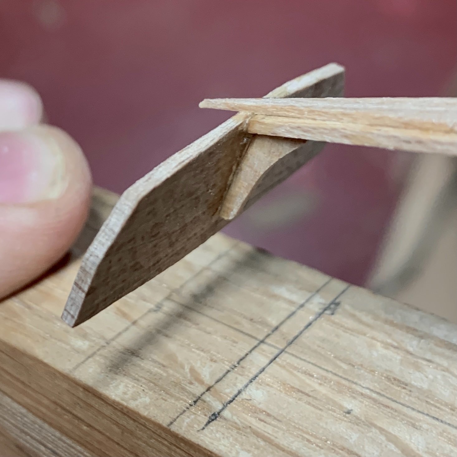
I’ve put one frame on. Or is it in? It’s in. This week, I so fortunate to find, on Craig’s List, someone selling a set of Proxxon tools lightly used for making doll houses. Just a 20 minute drive down the road. I bought a FET table saw, a drill press and miter saw for a song. Far less than half retail. These are great additions to my model shipyard and open up a lot of possibility in terms of this model and future ones. I was able to cut the “timber” for the frames with the table saw. <1mm square pieces. The pieces still need a lot of soaking to bend to the inner curve of the hull. I rushed a couple of times, but eventually put a piece in a cup of boiling water and walked away for about an hour. I spot glued the end closest to the keel first. The bottom ends of the frames are not intended to meet the keel as room needs to be left for the water to run through the limber holes. After the piece was in and the glue dried, I trimmed both ends. The tip of the frame closest to the sheer I severed at an angle to match that along the sheer. This angle should reflect the arch of the deck beams, so that all pieces meet flush with one another. Only 21 more left to do. Added the opposite frame just now.

-
Dennis and Bill, There is a very nice series of videos by Tom Lauria in Mystic, CT.: Building a Whaleboat. He describes, in an easy to understand way, a method of carving a hull. It appears similar to Bill’s approach. Below is a link to episode two, where he begins the process. I am in the middle of a scratch build, or maybe I’m at the beginning. Either way, when its completed I’m thinking of carving a small very small scale model. I’ll be following this build. Bill, I hope you are feeling better.
-
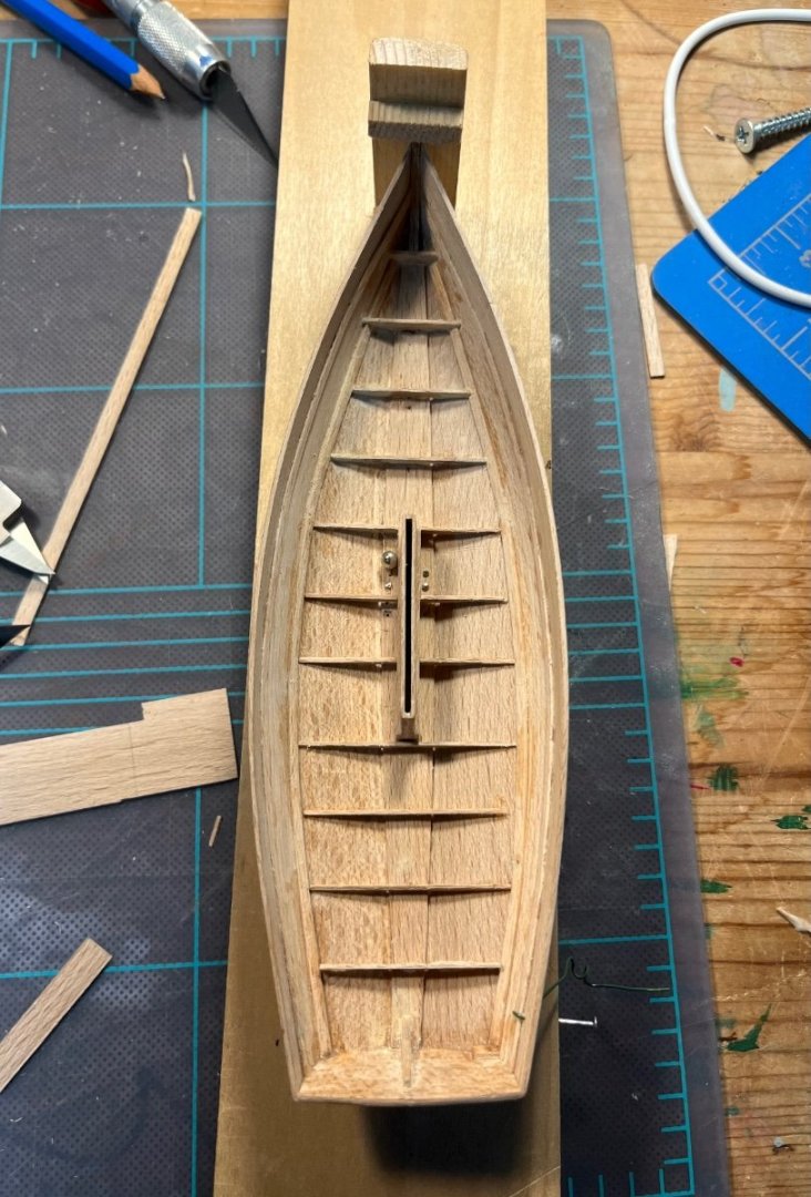
(FYI, there’s a question buried in this post that I could use some answers for. Thanks in advance.) Back with another update. I got the planks on. Removed the hull from the molds and found that the hull was twisted a bit. Turns out, this can happen even on the full sized version and the Wooden Boat articles that I am using as a guide suggest creating a jig or bracing to keep it square. I made mine out of a clear pine scrap, attached the hull with pins through the keel. I fashioned a bracket at the stem hold the boat firm. I drilled two very small holes on the starboard-side towards the transom. I inserted som wire through the holes and pulled down putting enough tension on that section of the boat to bring out the twist. I wound the wire around a small screw I had inserted into the piece of clear pine. I began to add the floors and it took me a while. Lots of mistakes and redos. As I move further into the project I can see plenty of discrepancies and need for wood putty. I’ve attached some videos to show my progress. I’ve since added all the floors and I need to put in the frames now. But there’s a dilemma. The pieces for the frames need to be a little less than 1mm square and I don’t know how to produce these “splinters” accurately and repeatably. Are there any tips besides just buying a Byrnes table saw? It’s made of beech so the plastic strip cutter I got from MM doesn’t work very well. I guess I could cut long pieces as close to square as possible and try to run them through my thickness sander… Lemme know please. This first video demonstrates the fit of one of my most successful floor pieces. FullSizeRender.MOV This next clip shows the jig and the shape. A close look will reveal that the top port-side stringer is a little lower that the one on the starboard-side. Also the stringers have a little kink where they met the molds. Most of this will disappear as I add the sole and frames. The sheer is almost mirror so that’s good. The centerboard trunk points a little bit to the port, too. Oh well. I’m having fun. Also, you can see the tool holder that I made in the background. Keeping my workplace a little tidier. FullSizeRender.MOV It turns out I did have a picture of the hull with all the floors installed.
-
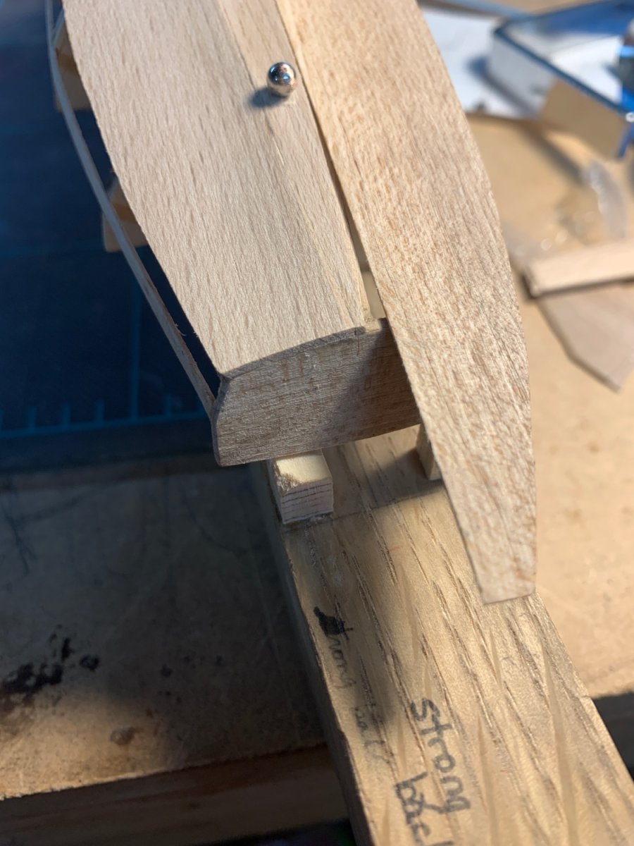
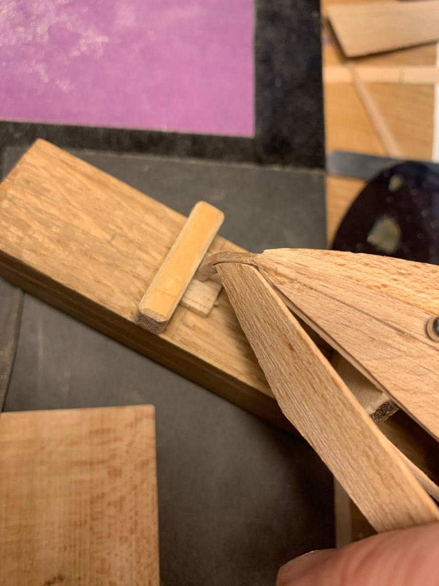
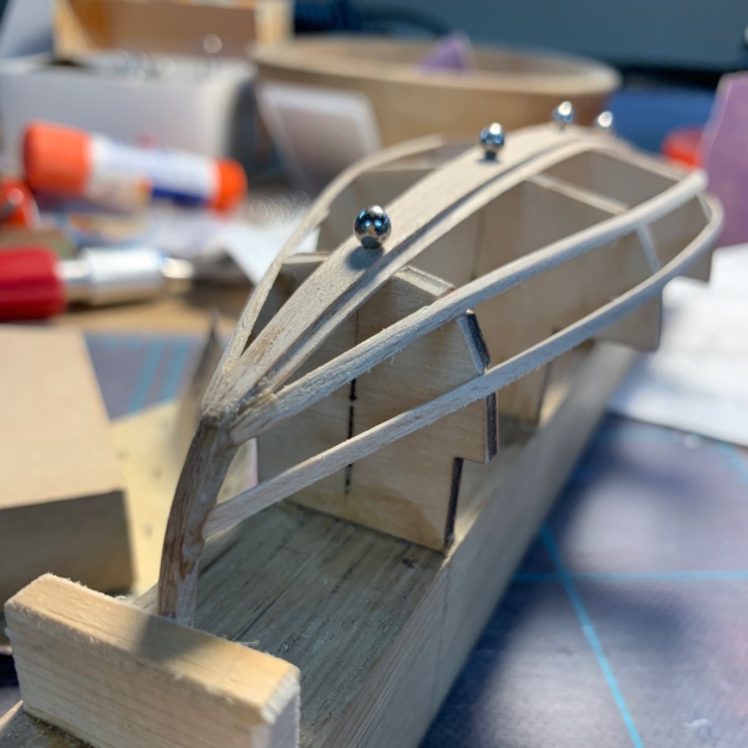
Wow, eight months later and I’m making another post. I’m just glad that I am continuing to work on this little model. I’ve got to go back a ways to find the photos and remember what I did. Namely the obstacles that I faced and the questions that I have. The photo below shows the keel, with stem and transom attached, as well as the four stringers. Note, and it will be more obvious as the build log continues, that I tried my best to mill parts to scale but with out certain tools it’s very hard at this size. By the time I was making the planks I had invested in a drum sander. The stringers needed to match the chine created by the mold as this would be, ideally, the edge where the planks met. So I used sand paper to create the angle along the stringers. Another bit about tooling. I eventually graduated to a card scraper to do this as it provides a much smoother finished quality and increases the chances that the parts are supposed to be flat, are flat. You can also see that I created “jigs” to hold the stem and transom in the right position. A block forward on the strong back to keep the stem down. And two blocks aft, beneath the transom to keep it up. Take a look at the bottom stringer on the port side, closest to us and, as it appears in the photo, on the top. You’ll see a small block inserted. That’s because one of the stringers was too short. Again, the time it takes to cut and mill pieces to scale with basically an Exacto knife, had me consider another solution. It worked. Sort of. after attaching the stringers, I ran into something that bugged me. One or two stringers did not rest completely flush on the molds. So, while some stringers were a hair too short, some seem to have been a hair too long. To address that (because I’ve learned that building a model is as much about fixing problems as anything) I made my second tool purchase: tiny drill bits. I needed to fix the stringers to the mold in such a way as I could remove the boat when the time came. So no glue. I also needed to do it in such a way as to jot split the stringers. So a tiny drill and map pins with the heads clipped off did the job. It was time to apply the Garboard planks. By this point, I think, I had purchased the drum sander and was able to make boards that were very close to scale, but more importantly, they were consistent with one another. The next photo shows the starboard garboard plank installed and faired to the stringer. I had also begun to carve in the angle of plank edge so that it would meet the next plank at the chine edge and with as much surface area as possible. This angle is a little sharp, I hope I brought it down a little. When I attached the port garboard plank I discovered another discrepancy in the build. The keel was slightly off. The amazing thing about this plan and boat is that it was designed in such a way as to utilize the natural tendency of the wood. So when I laid a flat edge of the port plank down next the keel (as I had done on the other side with a near perfect fit) I saw that wasn’t gonna match. So I filled in the gap. The next task, which was daunting enough to put things on hold for a while was attaching the other planks, two on each side. These planks had increased challenges because the the stem and had compound curves. I knew that cutting a rabbet was the right way to do it, but a dire mistake could have sent me almost all the way back to the beginning. I gave way to better judgment (see previous posts and responses) and cut the rabbet. I marked it with a pencil and used a Dremel and very small conical bit to make the curve. I finished it out with a the chisel I had used before. Very tedious and nerve racking but definitely worth the effort. That’s all for the time being. I have made a lot more progress, but this seems like a good place to stop. Some advice for other first time scratch builders or folks considering trying: don’t let mistakes, or the thought of mistakes, stop you from continuing or starting a build. I was drawn to modeling by the beauty of boats and the beauty of models. But the boats and models that we usually see, the ones on social media, or in magazines, are always the finest. Certainly inspirational, but the work of very experienced crafts people with lots of tools. So, I remind myself not to hold myself to those standards and have fun, laugh at myself and carry on. Until next time.


-
HMS Euryalus 1803 by rlb - 1:48 scale
Reverend Colonel replied to rlb's topic in - Build logs for subjects built 1801 - 1850
Indeed. Because it is also beautiful.- 122 replies
-
- 3
-

-
- Euryalus
- Plank-on-frame
- (and 4 more)
-
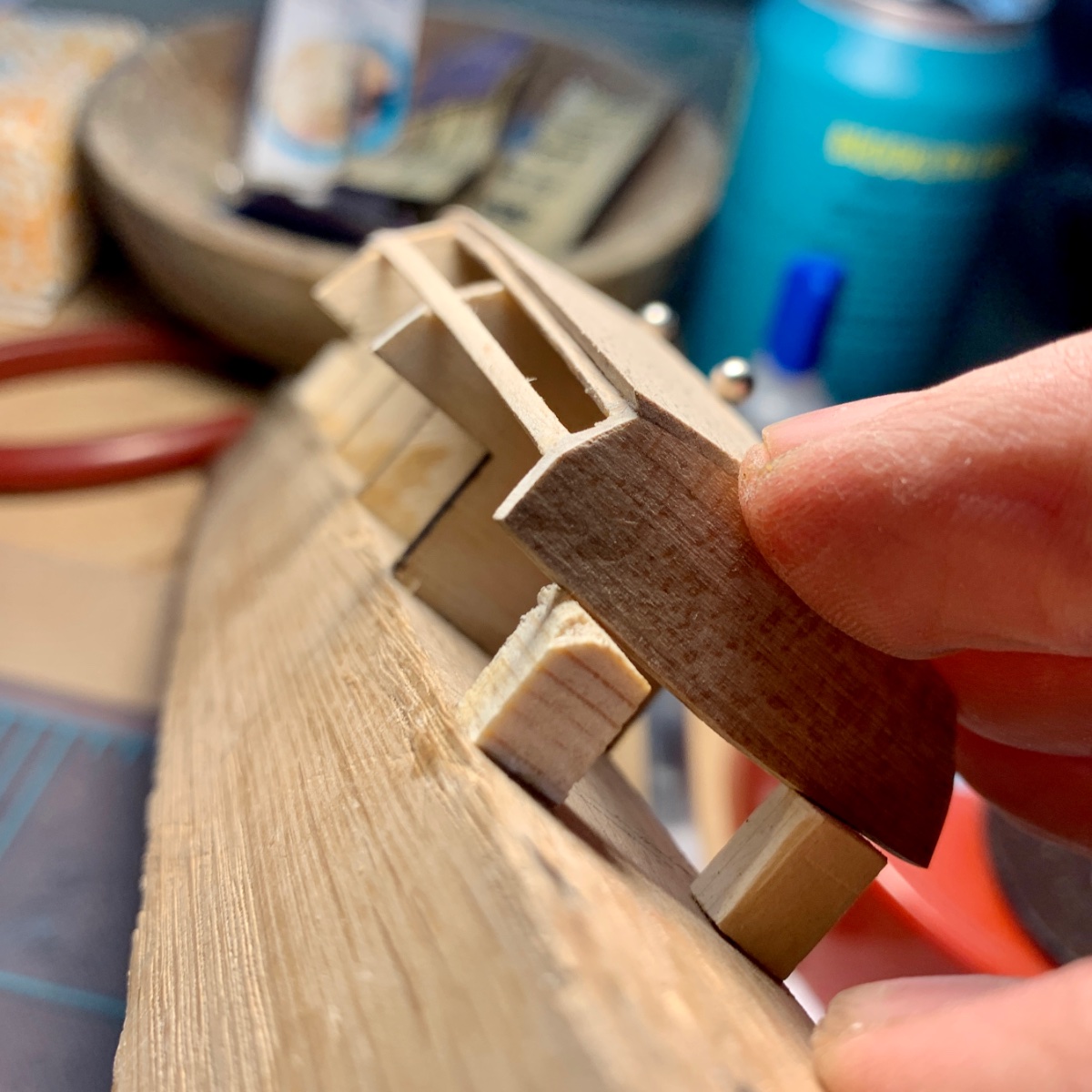
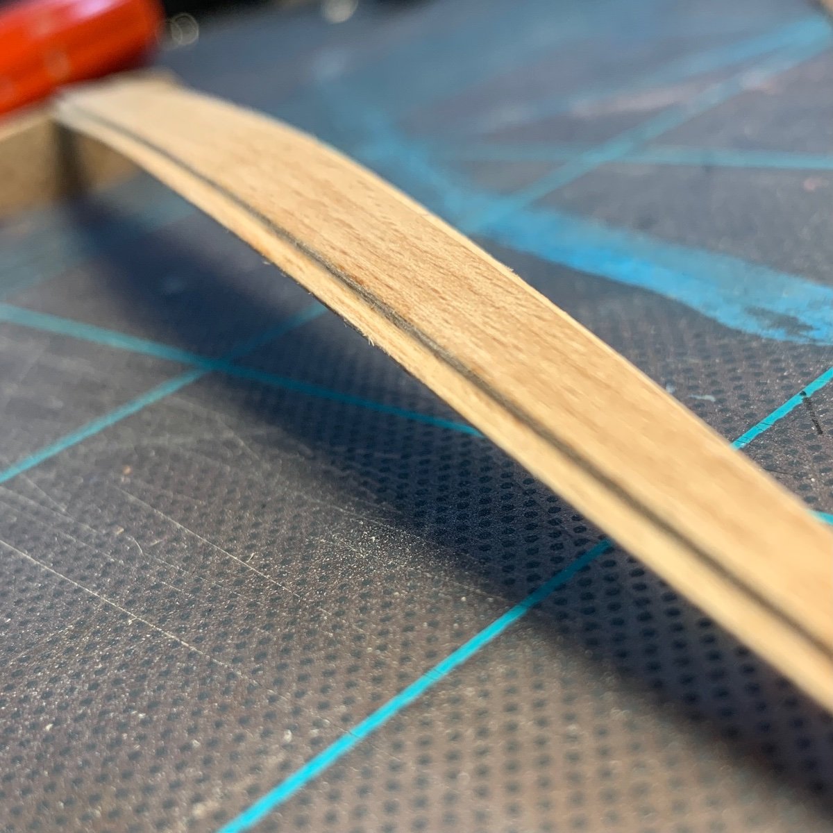
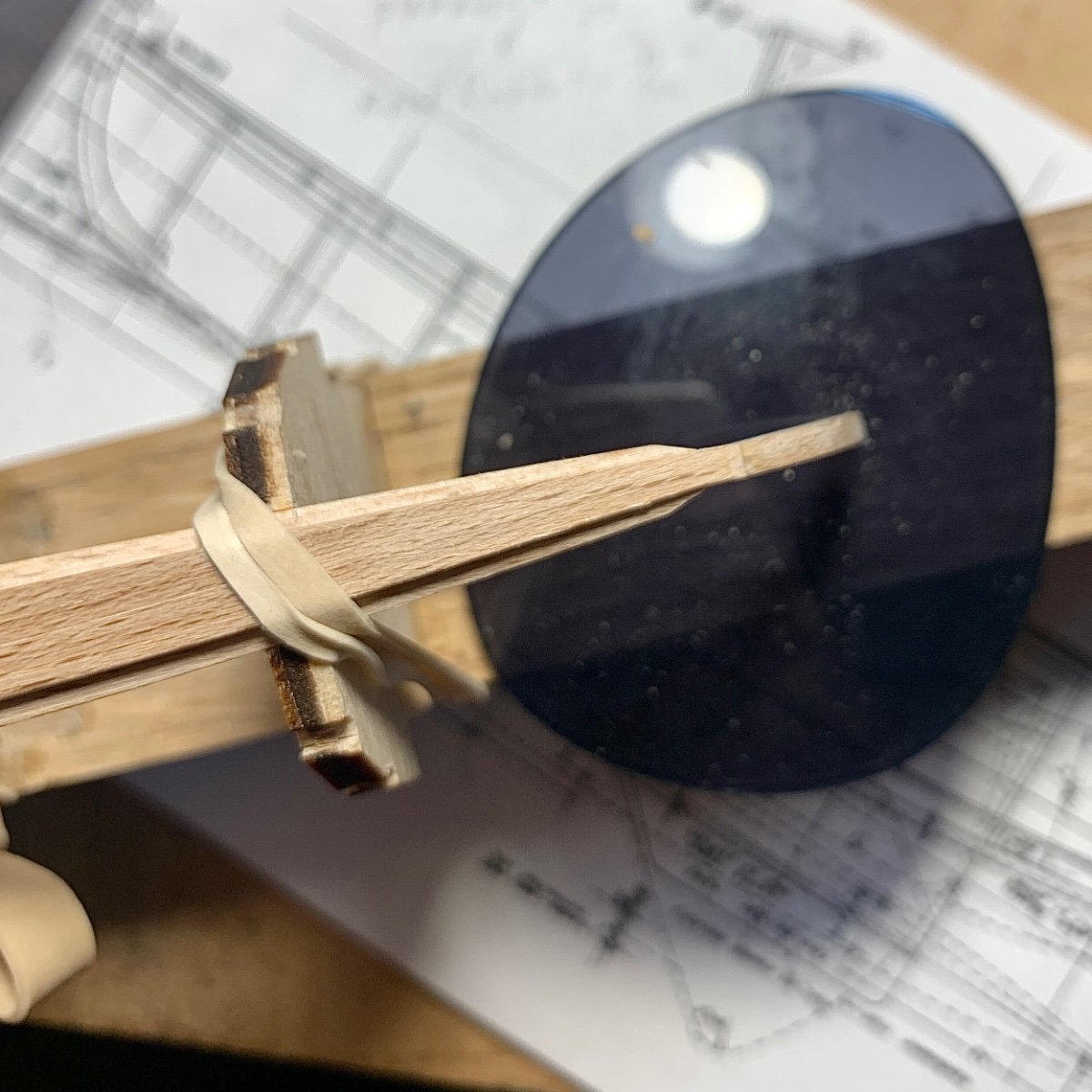
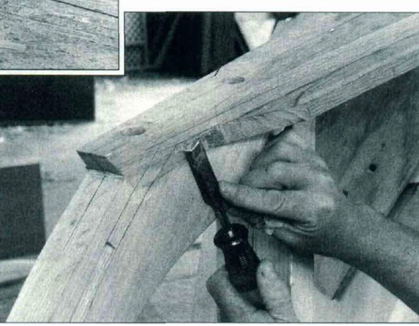
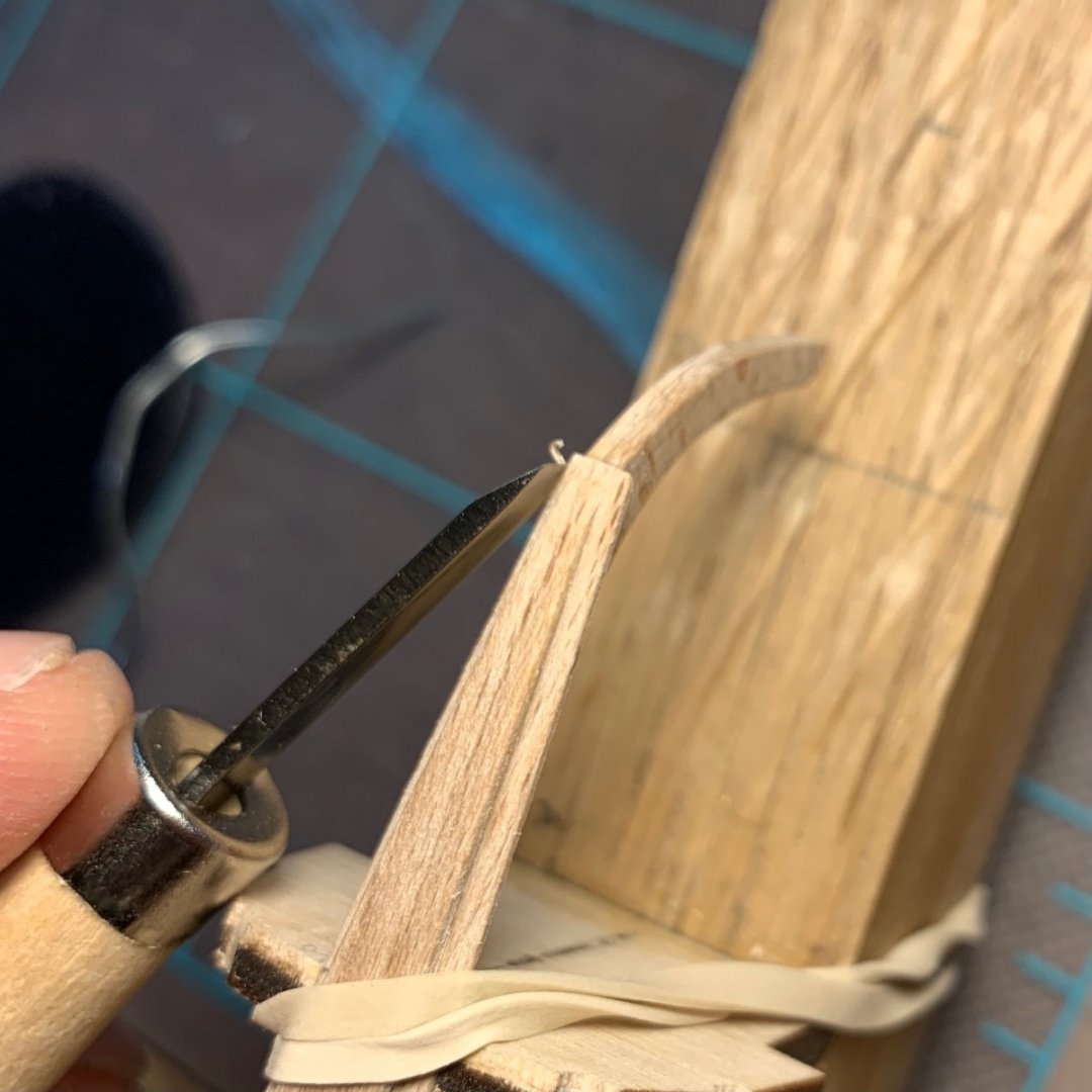
I’m glad to be back. I said I would return with more following Thanksgiving, but I should have known it might be longer. Having never made a wooden model, I’m only now discovering that each step requires a lot of consideration and time. Way more than I expected. I imagined that a smaller version of a boat would translate to smaller stakes, but with each step, carefully calculated, the potential wrong move could mean total collapse… Not really. Another thing I’ve learned is that it is especially hard to accomplish every step perfectly and part of the fun is figuring out how to correct (or hide) minor mistakes. Plenty of that to follow. I left off with the keel completed and the transom and transom knee attached. Before attaching the stem, I needed to bevel the rabbet to match the angle of the garboard plank. The photo below is the forward end of the keel… I made sanding files by cutting 1/8th inch strips of wood (about a 32nd thick) and glued different grades of sandpaper to each one. (180, 220, 3-something...) I cut off the excess with a blade. I used these to create the bevel. I also used a very small file. Here is a pic of the keel athwartship. My next step was to add the stem. It took me several passes to get the stem correct. The curve, the edges where it slides onto the keel, each angle is pretty important in regards to the final profile. In the photo below you can see the keel attached. I believe the pencil represents where the front of the stem should align to create the correct arch of the keel. Thinking about how to hold the stem in place - as well as the transom - gave me weeks of pause. I needed to have the stem and transom stable when I laid the planks. Thank goodness for the walk through of this build in Wooden Boat magazine. I would have been lost without it. The step-by-step, albeit with a lot left to self-discovery, has made this process less fearsome. Below is an image from the first of three installments that shows the shipwright carving in the keel to meet the stem. The would-be rabbet is marked in pencil. Here’s my attempt. I’m using a hand sharpened Japanese chisel. It came as part of an inexpensive set designed for carving wood blocks for printing. Eventually, I got there. With no gouges to my digits. An old sunglasses lens has been great for pouring in dabs of wood glue and using a toothpick to spread. When the glue dries it pops right off the lens. Until next time…


-
I get this. This is why a full sized ship bandsaw has an adjustable bed that changes the angle of the cut as you pull/push a plank through it.
-
Thank you so much for this little bit on cutting a rabbet. I am also making a small model of a small boat and this technique is can be practiced and uses hand tools, which I prefer.
-
LJP I grew up on the Ohio river. A big fan of paddle wheelers. I have a feeling that my first “big boat” will be the Seawanhaka. A Long Island Sound steam ship with the wheels on the side. I believe it was built in 1860. Anyway, enough about me. I’m following this build. Very cool. By the way…how did you make the boilers? What materials, paint…and the rivets…small brass bits…all of the sudden the boilers appeared in all their glory...whatever the case, they look great. Thanks for sharing your build. RevCol https://modelshipworld.com/topic/30548-biscayne-bay-sailing-skiff-by-reverend-colonel-124-small-made-from-a-beech-log-ng-herreshoff-design/?do=edit
-
Roger & Keith: Thanks for the replies. I am thrilled to enter into these conversations with others who share the joy. I think problem solving and the way model making is all about the time in between the steps (not just the work of the steps) make it a great antidote for the “world’s” pressure to complete as much as possible as quickly as possible. Already, an application of hot water to the keel has relieved some of the bending pressure forward of station A and the stem is in the position necessary for attaching the stringers. This is all fodder for the next post. Which may make this a worthwhile point to mention the next steps, as way to invite some more considerations and speculations. Should I bother to carve a small rabbet in the stem to receive the planks? It seems like a toss up. If I was entirely confident I know it would be the best option. But is the pay off worth the risk for a first time builder? Otherwise, I’d have to bevel the planks to meet the stem with the most surface area. it’s a very detailed maneuver and in the end I’d like to rely on filler as little as possible. Ok. Talk again soon. JWL
-
Ccoyle & KeithAug, thank you for the likes and interest. I know that much of the first post (particularly the text) may seem very 101, but I’m focused on describing some of the basics for other first time builders in order to share info that I had been looking for when I first began scouring this forum. I do have some questions and maybe the two of you can help me answer them. The forward portion of the keel, which includes the stem, needs to be pulled down a bit, the curve beyond the first station needs to be a little deeper. I used waterproof wood glue to laminate the keel and attach the stem, transom and transom knee. To possibly assure some natural curve to the keel and take the eventual pressure off of the stringers and garboard plank I was hoping I could dampen the keel with a little water. Could this jeopardize the integrity of the keel? Model making appeared to be a low stakes entry into boat construction, but with each steps the stakes increase and I’d like to avoid ruining the work I’ve done. In a similar vain: can I use a PVA that is not water resistant to create a bond that I could detach later? By using water? Or rubbing alcohol. thanks.
-
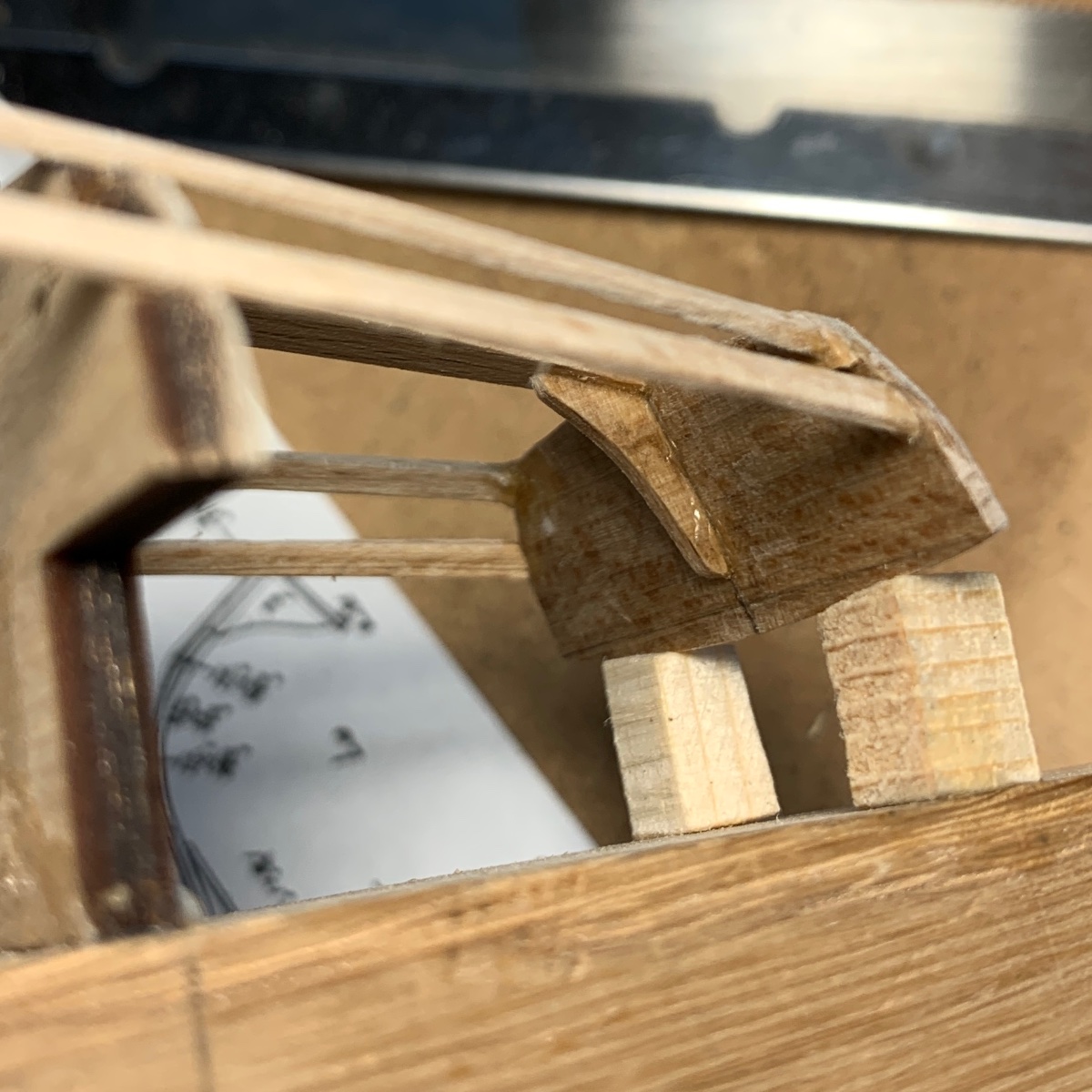
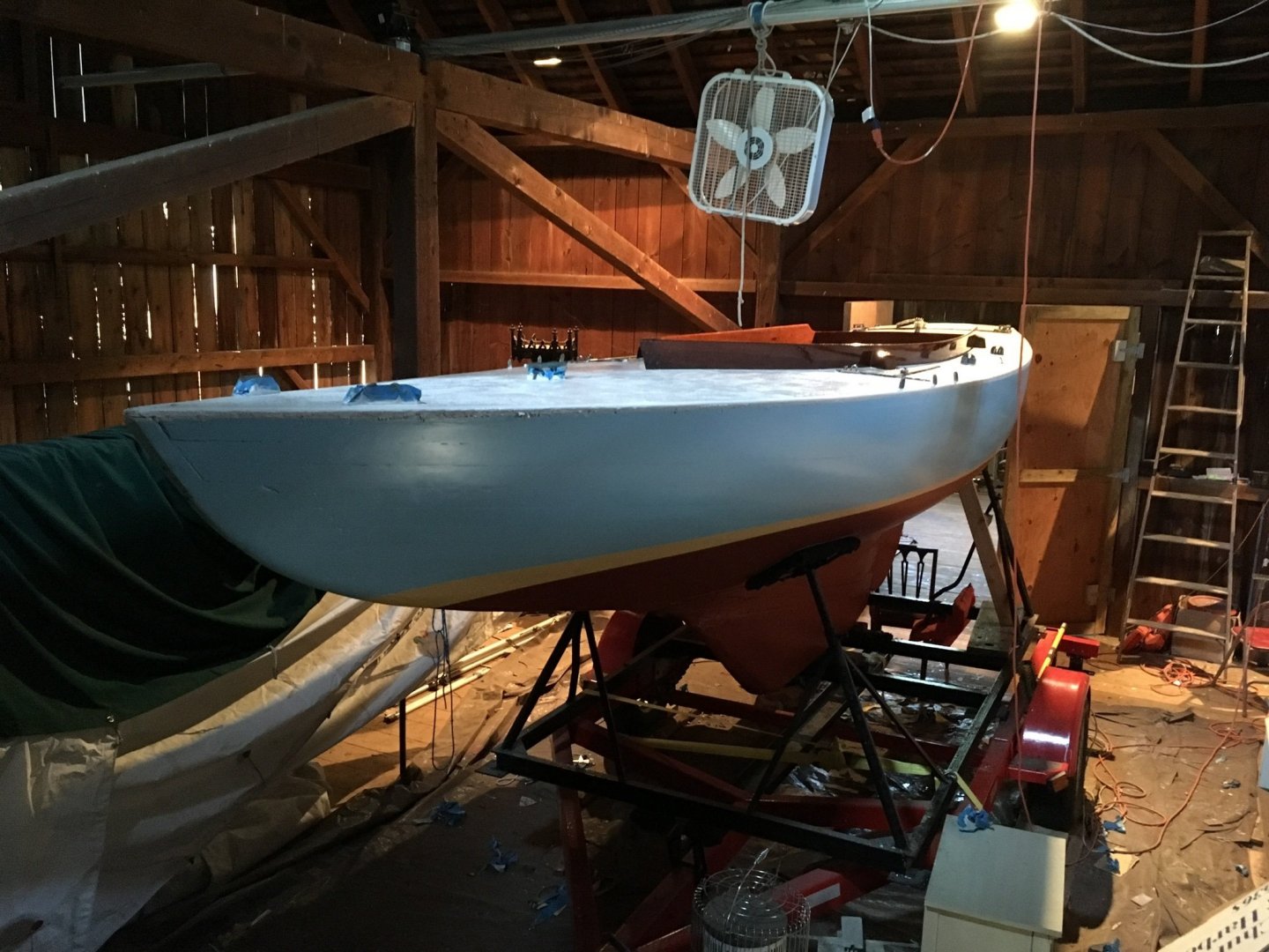
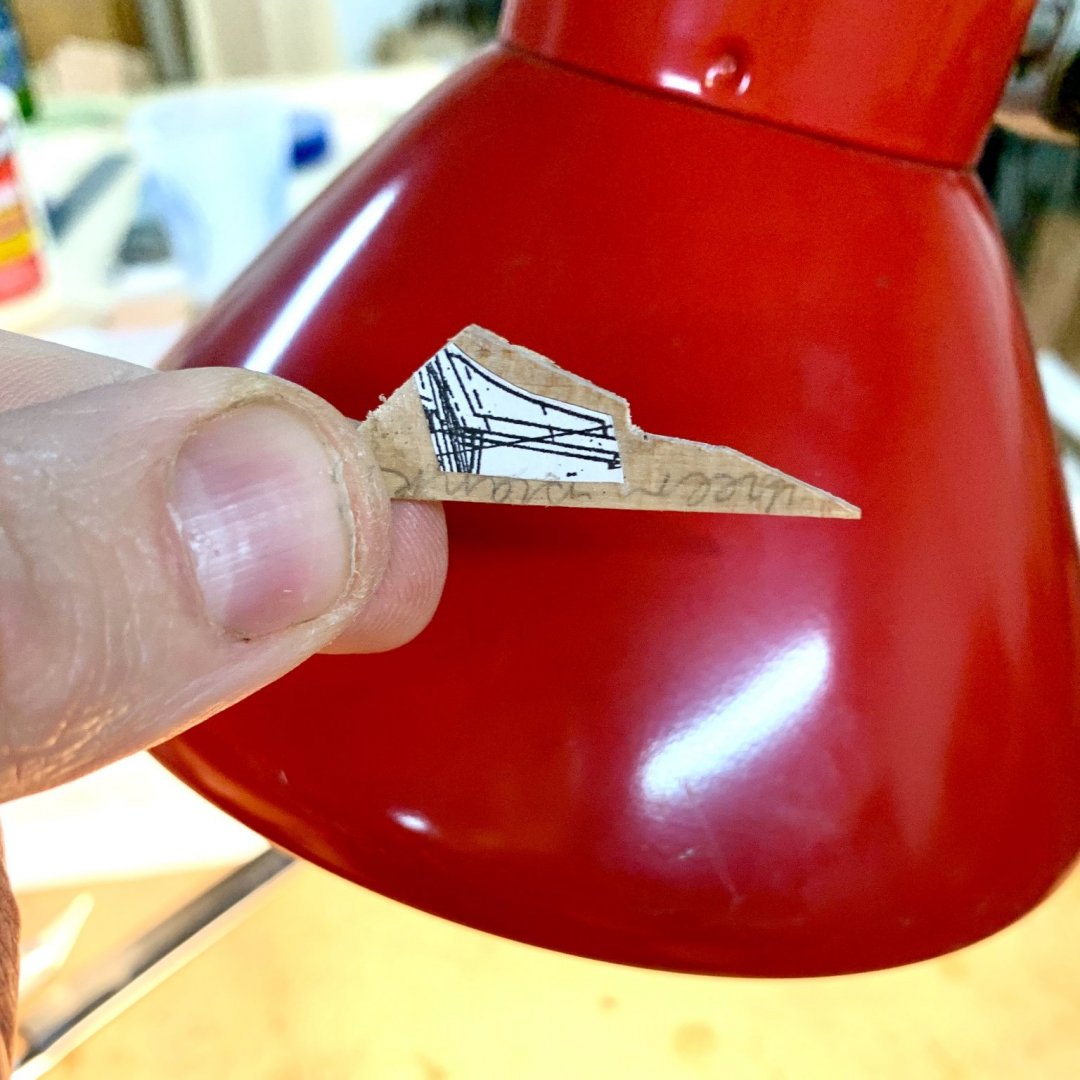
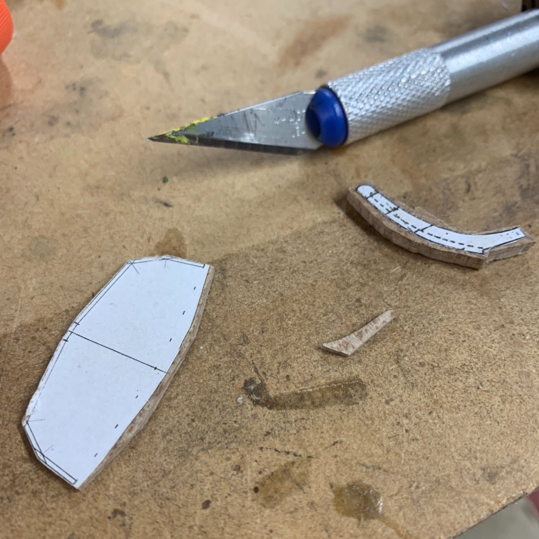
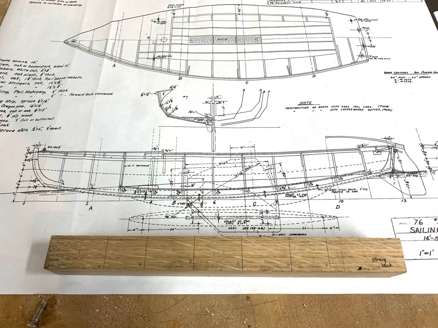
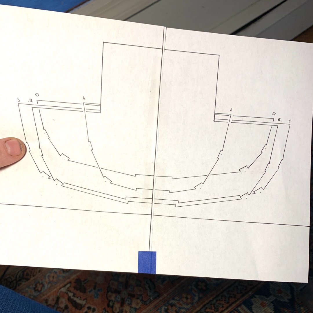
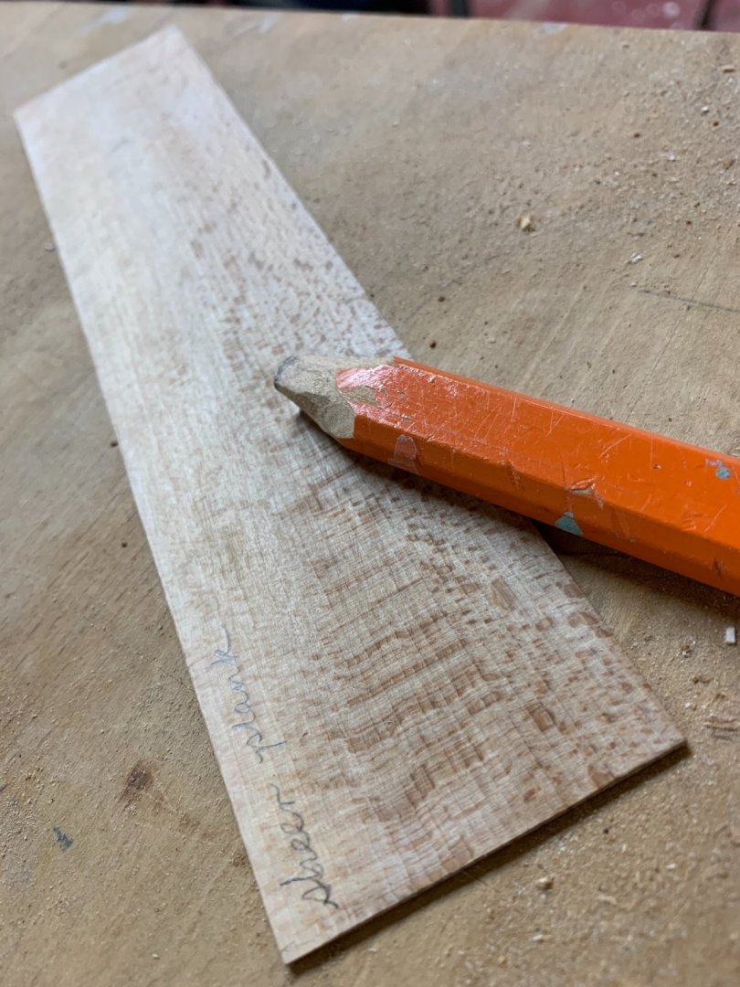
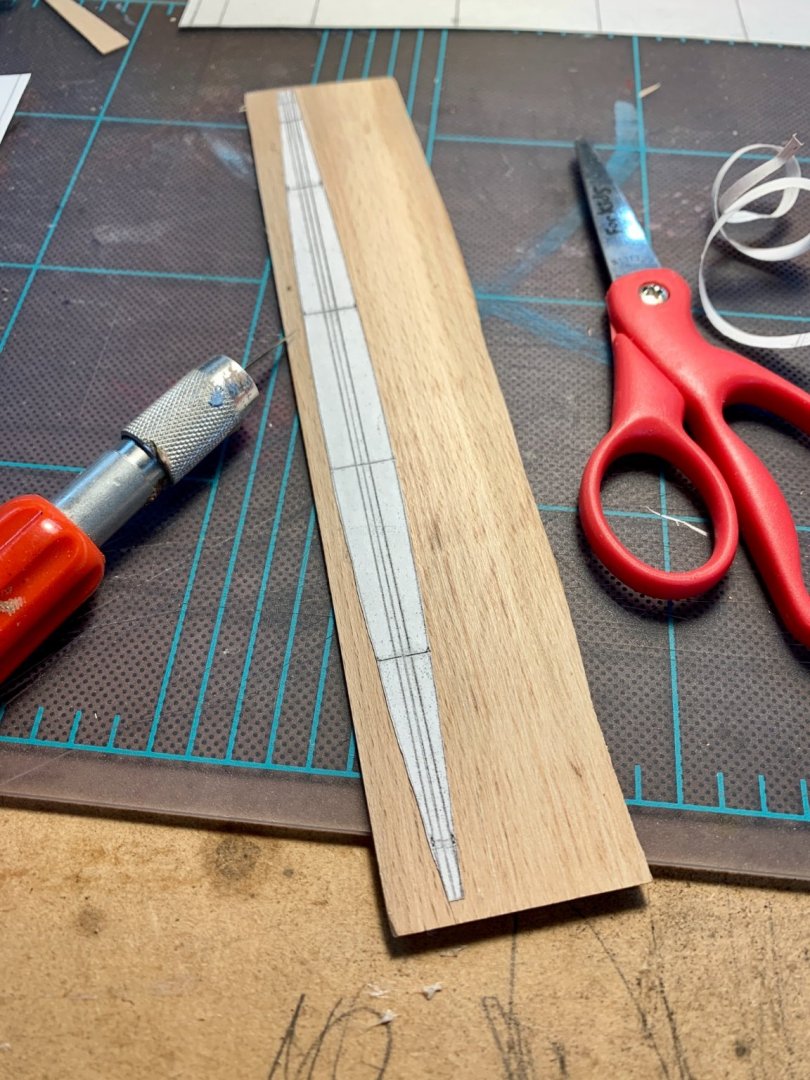
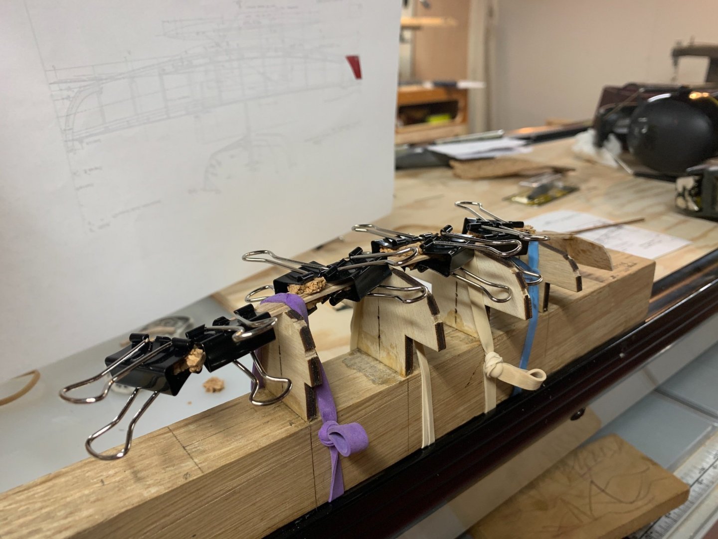
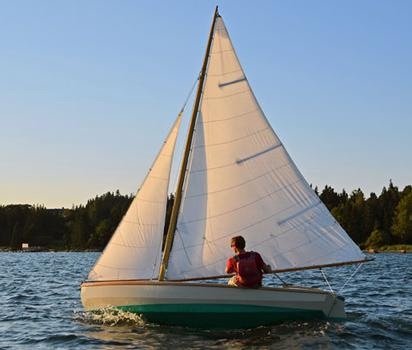
Greetings. Up until a month ago it had been 30 years since I’d made a model, and no disrespect, but it was just a plastic car; parts included. Maybe 20 years ago a friend invited me into the back of her parents’ garage where her father had set up a shop. Scratch builds upon scratch builds. Last year his work was displayed at a museum in our home town and the memories of his shop surfaced. There’s a video, too, which I’m sure you’ve all seen. Apart from the style of the documentary, which was lovely, the subject matter and the modeler’s philosophical approach pulled me deeper into the archetype. And then, I’m a sailor. A recent convert (6 seasons) but flush with zeal. Our first boat was a Manhassett Bay One Design, which I refit over the course of two winters. The pics of that boat, 23 SKIDDOO, follow I have also been harboring an interest in milling lumber, which occasionally rears its ugly head in hours long binging of sawmill videos, and has also lead to my small collection of logs from local trees: beech and apple. So many pieces of the puzzle were in place (more than I’ve illustrated here) that when I happened upon a copy of Thirty Wooden Boats and saw the Biscayne Bay Sailing Skiff I knew I wanted to make a model of it. I want to make a full size one, too, but there aren’t as many pieces of that puzzle falling into place. I believe this boat, which I’ve named Rigel, is a suitable first scratch build for a number of reasons. The plans are good. The hull is double chined. WoodenBoat magazine documented a build of this boat step-by-step in three installments (#s 96, 97, 98.) So, a relatively uncomplicated, beautiful design that comes with some directions. I harvested a beech log from the woodpile at Planting Fields in Oyster Bay, New York. It came from the limb of a tree that was part of an original copse. The landscape of that estate was designed by the Olmstead Brothers. Here’s a piece of quarter sawn beach that I milled, it would become the transom, transom knee and stem. Primary tool so far: photocopy machine. I intend to build the boat as it would be at full size, so using a photocopy machine, a digital caliper, a light table and some fine drafting pens I mocked up the molds. First I increased the size of the plans 200%. Then I traced the section lines, printed a mirror image, lined up the two sides and made a reduced copy until I got the scale I wanted, 1:24. One inch equals 24 inches or 2 feet. The section lines represent the outside of the hull so I had to compensate for the planking. This image is of the 1:1 plans with a squared piece of white oak that I’ve used as a strong back, to which I attached the molds, eventually. You know when I saw that this was the size of the molds I thought I had lost my mind. The notches seemed minuscule. I feared endless frustration as I began to try every method possible for cutting these shapes out of doorskin. Eventually, I called my neighbor who has a laser cutter. She definitely helped me out and I might have bailed on the project if it weren’t for that little boost. Accurate molds are crucial for a decent final product…I’ve heard. That being said, I am not sure I would feel comfortable using a laser printer to cut pieces that would actually be used on the boat. But that’s just me. After getting them cut I had to attach the molds to the strong back. There were a lot of steps to this. Drawing out station lines on the strong back, gluing the molds down, using legos to get right angles…starting over. Lining up the molds correctly, in relation to the station lines and the sweep of the keel…eventually I got it. With this part in place I was ready to start working on the keel, which is essentially a plank with a large rabbet removed from the edge to fit the garboard plank. How was I going to cut a rabbet into this plank? I wasn’t. I “lofted” the shape of the keel, used some photo copy magic and created two templates: one for the wide portion of the keel and on for the narrower rabbet piece.I glued them together to form one solid keel with a rabbet “cut out.” I used glue stick to attach the pattern. I rough cut then sand to shape. Here I’ve glued the transom (and knee) to the wider keel piece and dry fit the Rabbet with rubber bands. Glued and clamped. I use those office clips with bits of cork to dampen the squeeze. The rubber bands keep the keel bent. When the glue dried and the keel came off the molds, the curve was holding. . I’ll leave you with one image and then, until next time… peace. See you after Thanksgiving.


-
Good one! Great models, great display, great sentiment. It’s the a model made in the right spirit that always looks the best! Also a great inspiration for a model I’ve just begun.
- 84 replies
-
- 1
-
-
- knockabout
- finished
- (and 2 more)