Peter6172
-
Posts
182 -
Joined
-
Last visited
Content Type
Profiles
Forums
Gallery
Events
Everything posted by Peter6172
-

EURYALUS 1803 by Peter6172 - 1:48
Peter6172 replied to Peter6172's topic in - Build logs for subjects built 1801 - 1850
OK, so after engaging with a couple of the more expert members of this forum, I have chosen to remove the sternum knee, transoms, fill frames, stern post and Keelson 6. This was simplified in that Russel had used PVA and I sprayed the joints with Isopropyl Alcohol.. I can now get the STBD fashion piece vertical. It appears that the model has rested untouched for several years and with the recent very hot dry summers and cold wet winters there has been much movement I the timbers. The only way to remedy is to partially dismantle and in some case remake parts (as not all parts came out unscathed).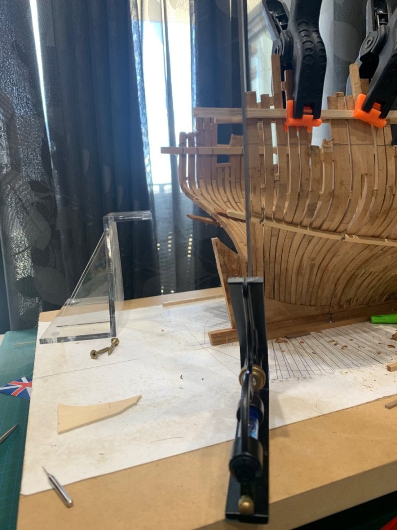
-
EURYALUS 1803 by Peter6172 - 1:48
Peter6172 replied to Peter6172's topic in - Build logs for subjects built 1801 - 1850
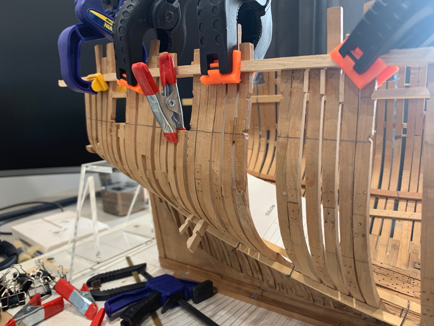
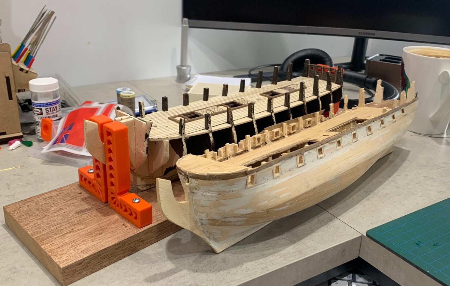
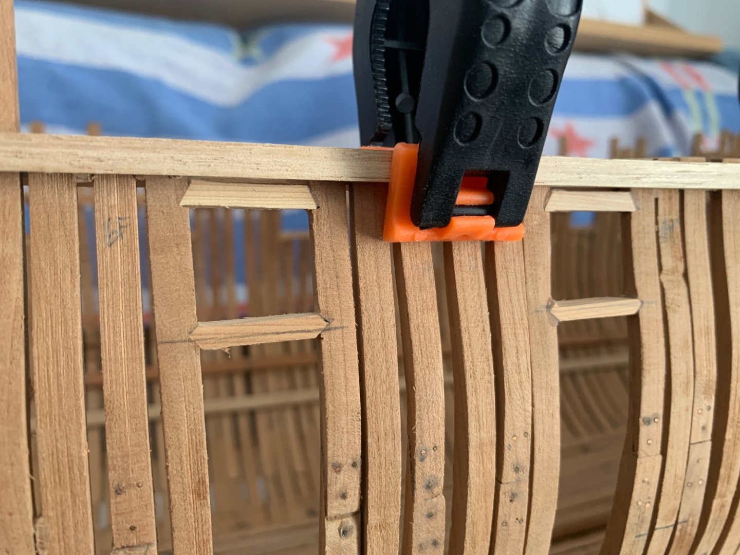
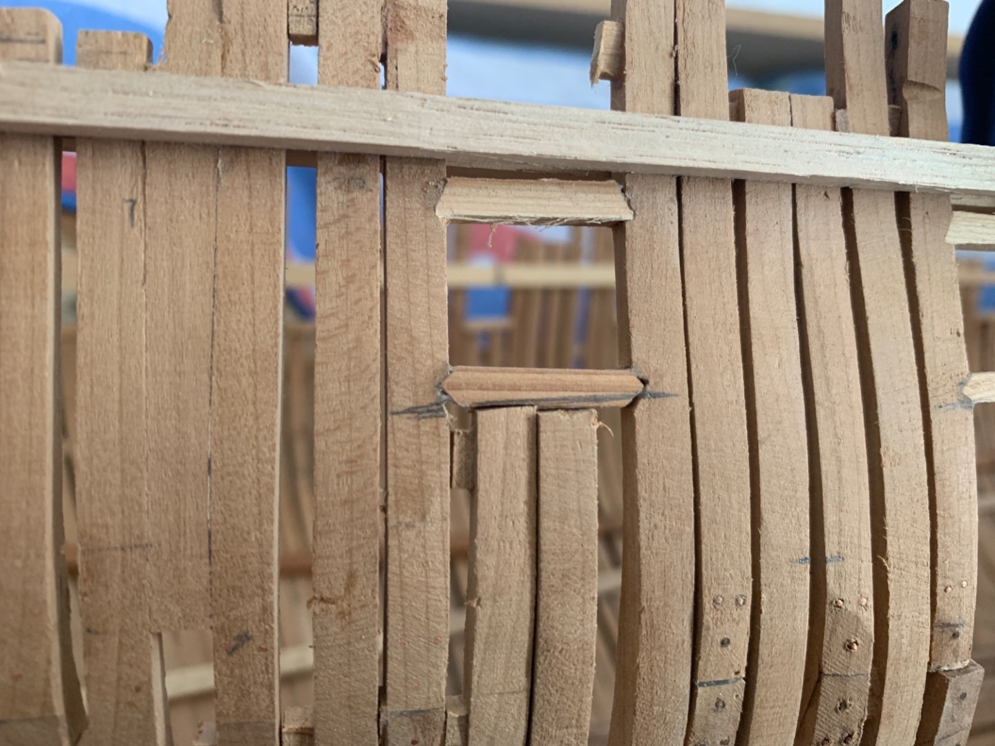
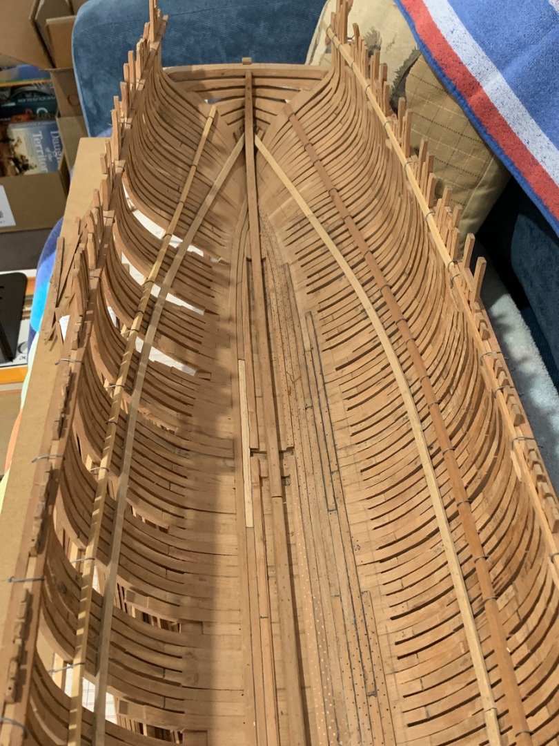
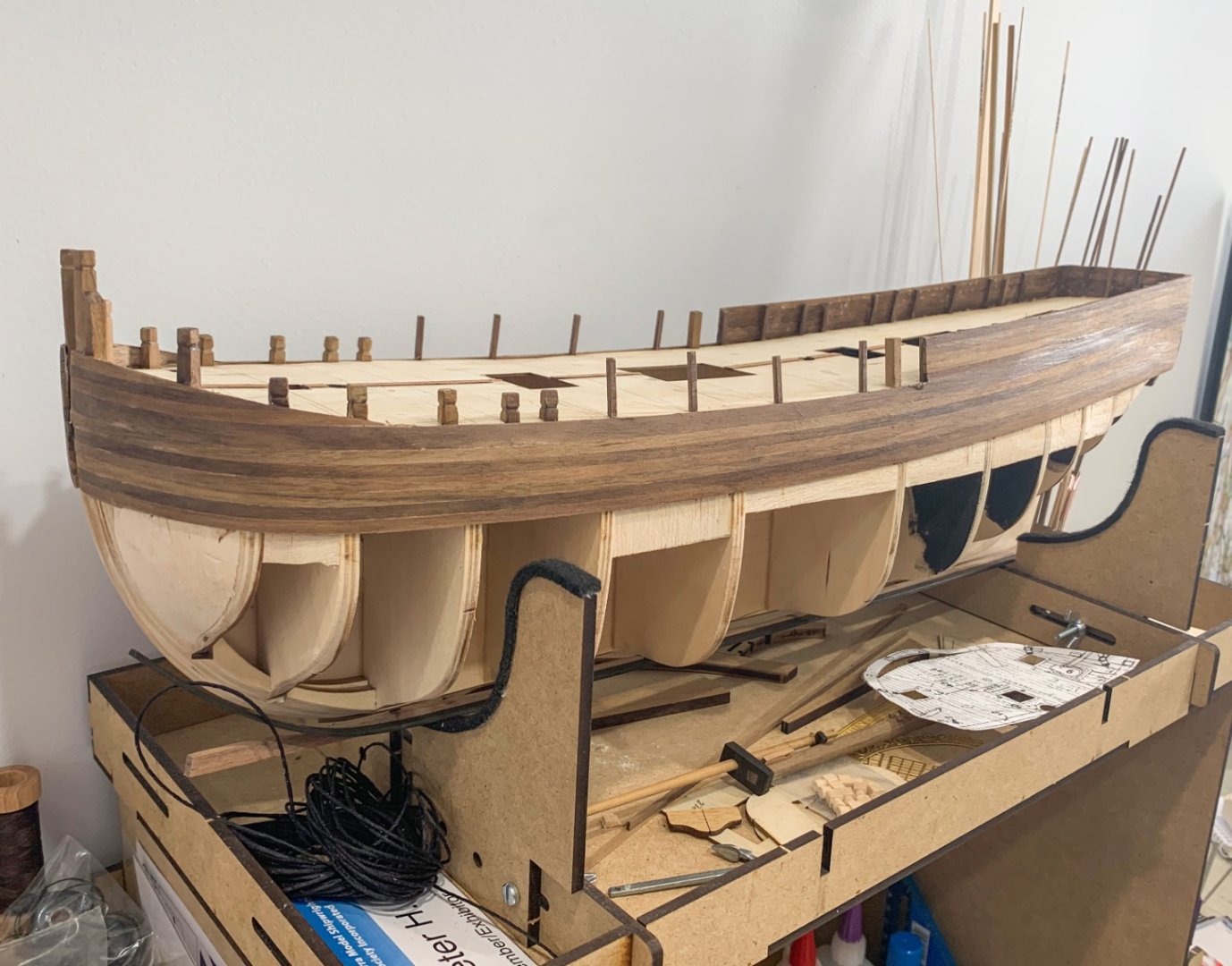
Well I have cane through and made vertical all the frames on the starboard side. I just need to replace the gunport sills now but first I need to find the right height of the sills per the plan. I marked them on the frames and then joined the marks with a batten running the whole length to ensure that the line was fair and aligned with the sheer. At this point I found that top piece of frame 23F had cracked at the top of the chock; its narrowest point and most likely occurring when I removed the lower gun port sill. I have chosen to glue and clamp it back in place at this time. I will review this decision after removing the clamps. The dark pencil line in the images shows the new centreline of the gun port lower sills per the drawing. I have a few notches to patch up first before cutting the filing in the new notches. As I understand it, the bird beak lower sill looks to be about 120º and the top sill about 75º. For simplicity and consistency I plan to do 90º (using a square file) and 60º (using a triangular file) respectively. I will then mark out the upper deck gun port lower sills, lay a batten to check alignment to the sheer and then file and install these lower sills. Finally I will mark in the position of the hull mounted blocks, air gaps sills, and sweep positions and file and install the blocks and sills. Cannot do the main cabin window sills as I haven't built up the rear framework onto of the transoms. Once I have all the new sills in place I will then move to check the Port side. As the interior of the frames has already been faired, I will give them a light sand (as there has been some relative movement of the frames) and the make up and install all the deck clamps. This should stiffen the skeleton enough that I can remove the battens and then

-
EURYALUS 1803 by Peter6172 - 1:48
Peter6172 replied to Peter6172's topic in - Build logs for subjects built 1801 - 1850
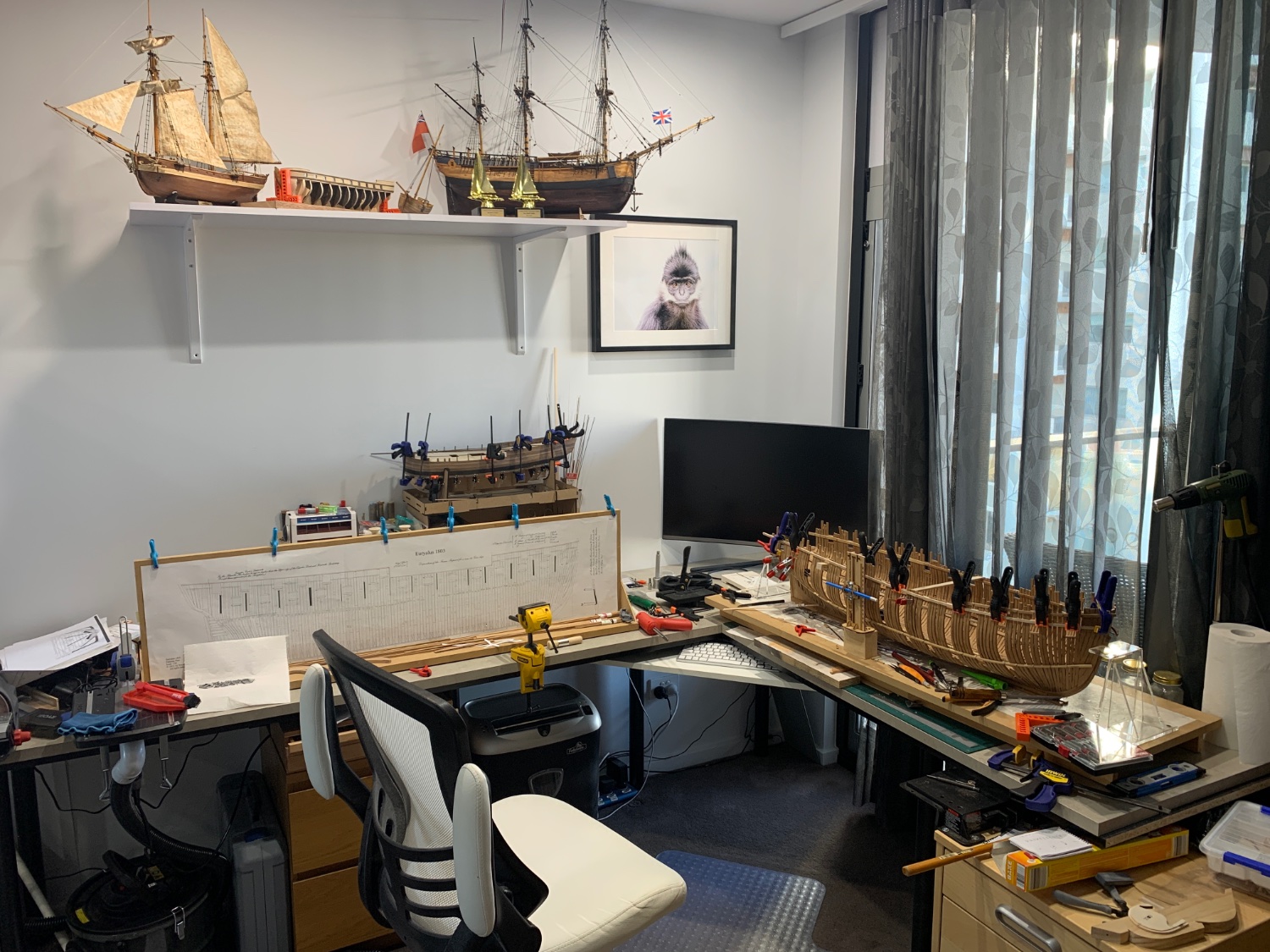
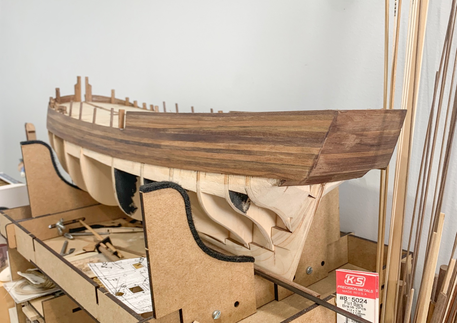
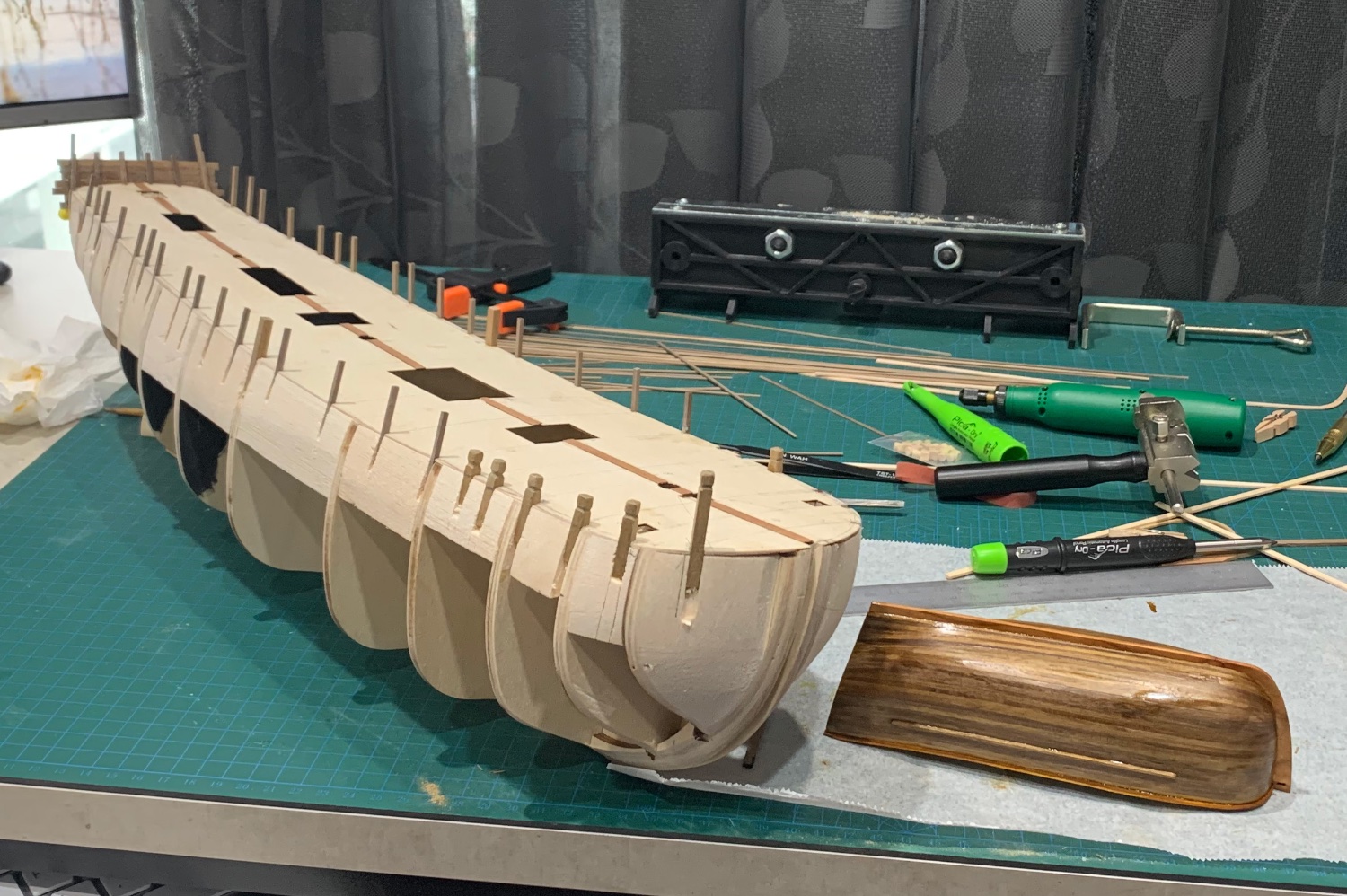
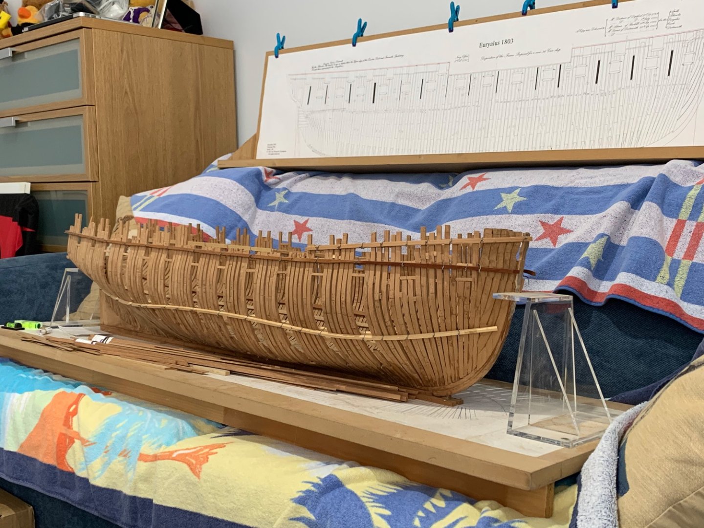
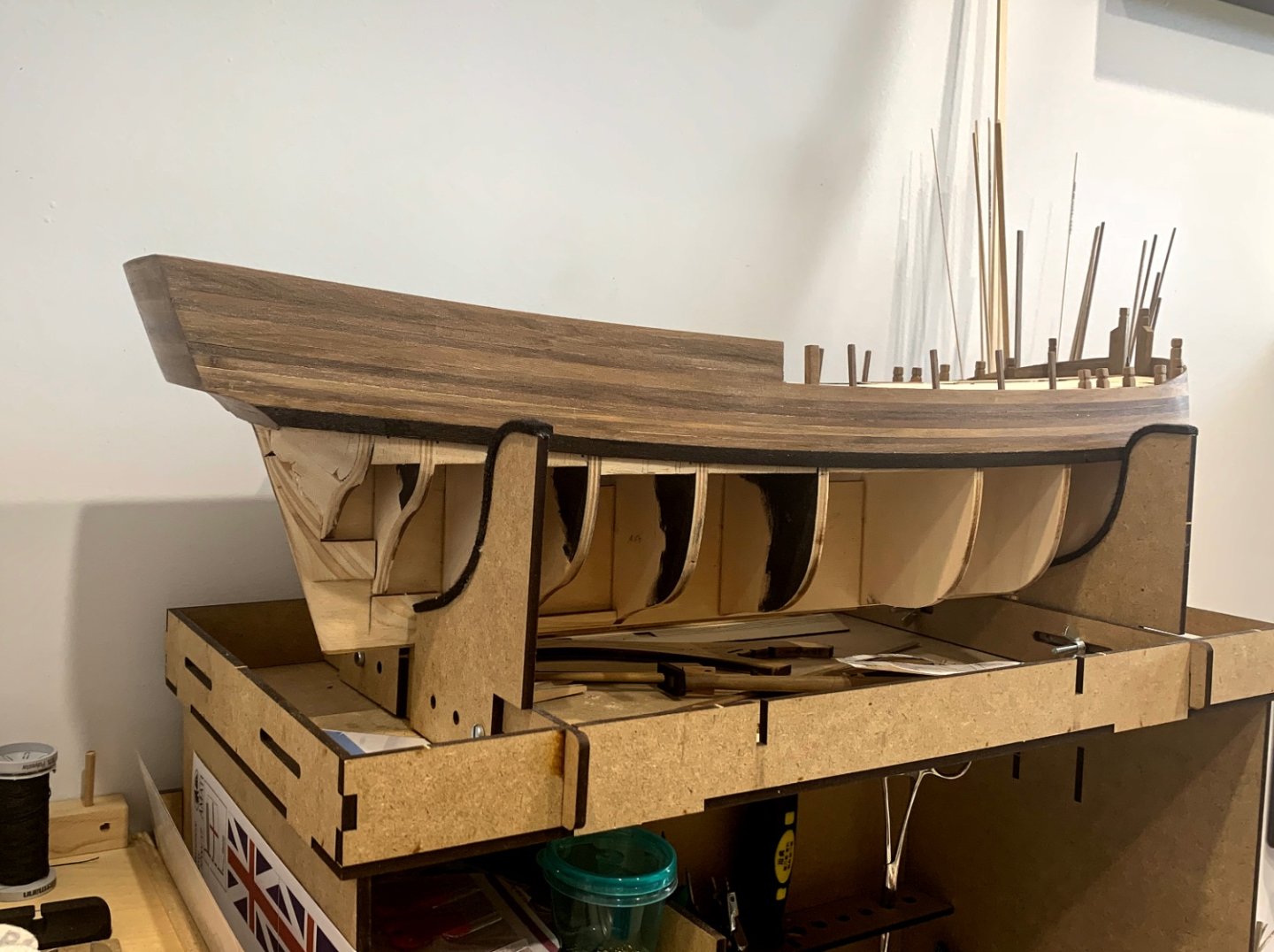
Moving things around to see what space I have for ship building. Certainly a little tight but not impossible. Have levelled up EURYALUS so that she sits level on the building board both fore and aft and athwartship. The outside sheer batten has been fitted to slot into the rabbet on the stem. I have started removing spacers/fillers so that I can straighten up the frames so they are vertical and started removing and replacing the gunport sills. The Gunport between Frames 16 and 18 is drying with the gunport gauge in place,. I have also removed and replaced the broken chock on Frame 22F. The copper pins are well and truely fitted to I might just rely on the resin glue to hold it in place. Once the framing is completed I can relegate the elevation to another room and free up 2m of bench space.
-
EURYALUS 1803 by Peter6172 - 1:48
Peter6172 replied to Peter6172's topic in - Build logs for subjects built 1801 - 1850
Great news on the Bow Piece. A little trimming of the gripe and the bow piece fits the drawing like a glove. A little shim strip on the stem will fill the gap where the stem shape does not quite conform to the drawing. Got to be happy with that.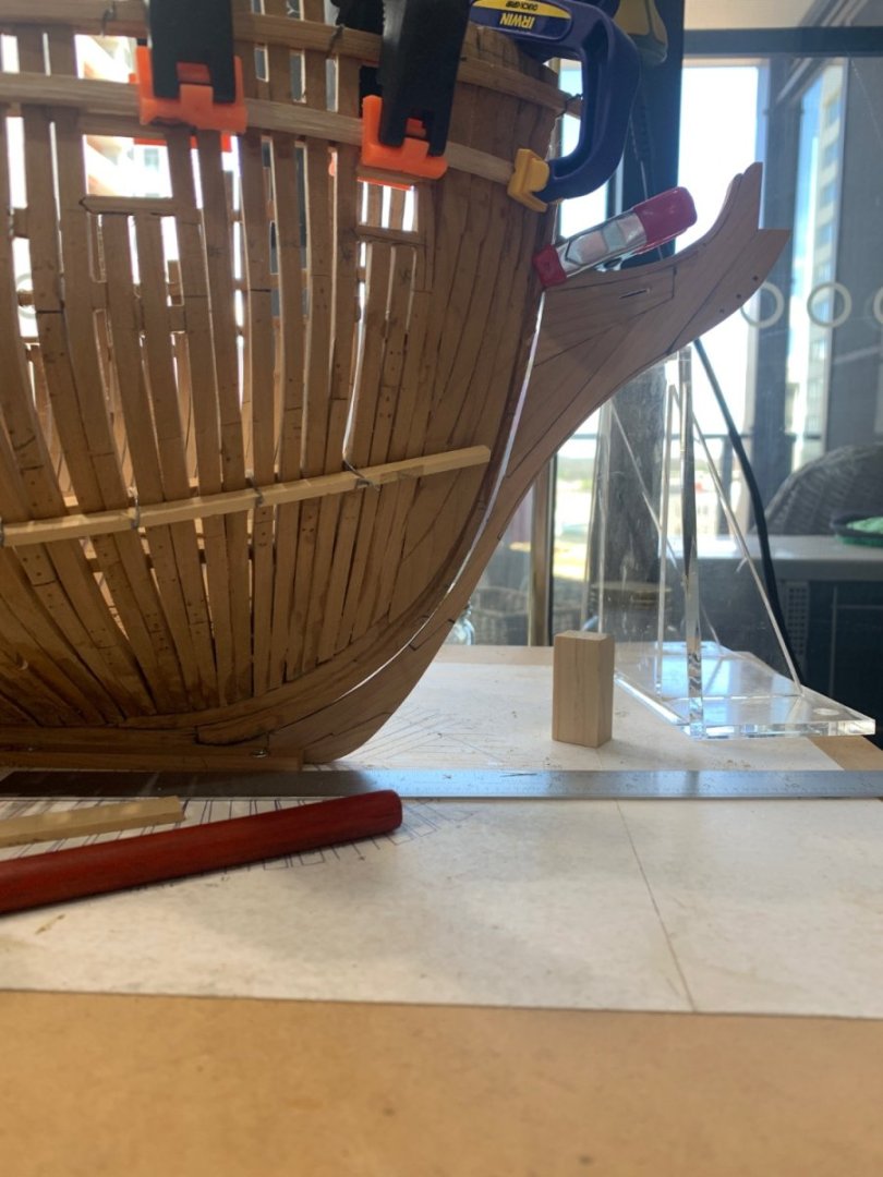
-
EURYALUS 1803 by Peter6172 - 1:48
Peter6172 replied to Peter6172's topic in - Build logs for subjects built 1801 - 1850
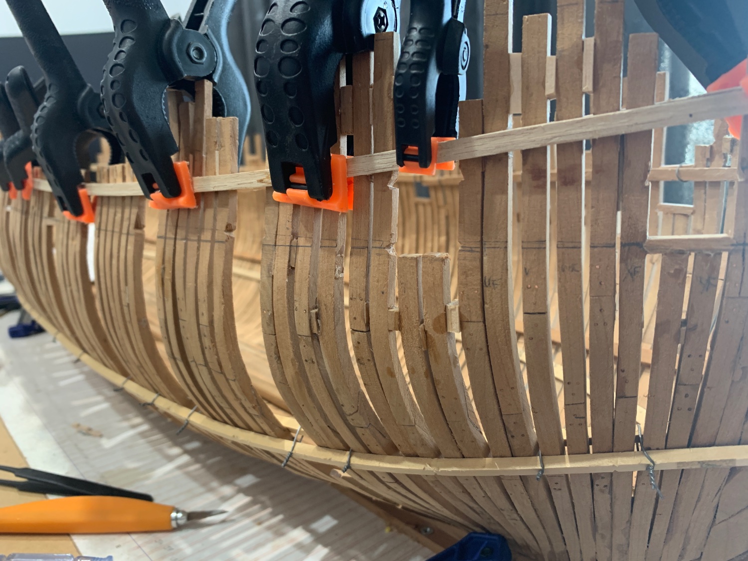
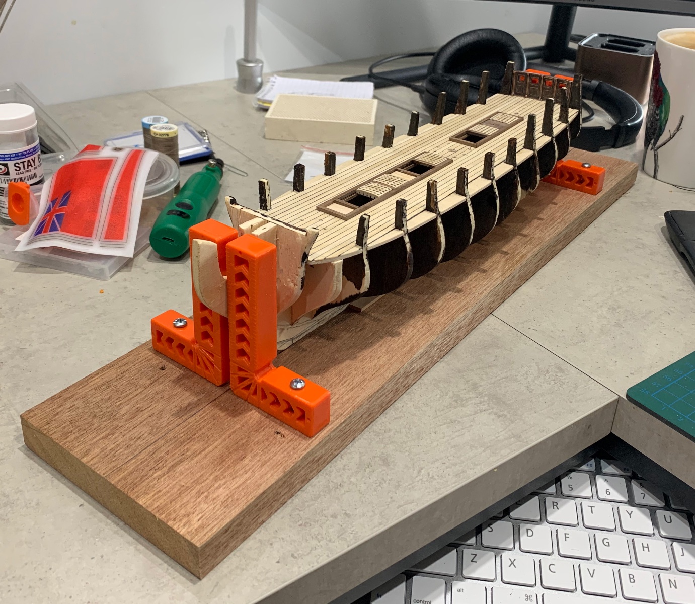
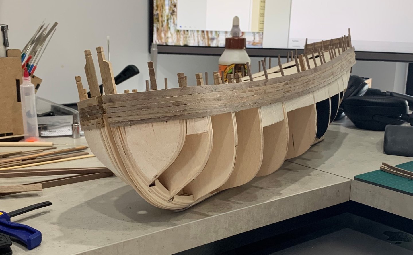
I have made up some sturdy 5 x 5mm Tasmanian Oak one piece battens to stiffen the sheer of EURYALUS. I then checked heights against the datum with a height gauge and found that some of the cannon port sills are not quite in the right position (pencil line is bottom of the sill). First photo also shows the fractured joint where the chock between the futtock joins failed (far right frame). I have also made up a gun port gauge (bottom image near the bow) from Tasmanian back to check the frame space and sill spacing to make sure they are all the same. Unfortunately the port sill is in the right position but I will have to remove the futtock to remove the chock and fit a new one. It will be delicate surgery as the lower futtock will also need to have the broken chock removed.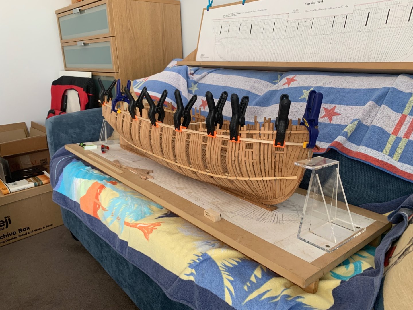
-
EURYALUS 1803 by Peter6172 - 1:48
Peter6172 replied to Peter6172's topic in - Build logs for subjects built 1801 - 1850
If one didn't taper one would have a real problem getting a figurehead mounted.... -
EURYALUS 1803 by Peter6172 - 1:48
Peter6172 replied to Peter6172's topic in - Build logs for subjects built 1801 - 1850
Drilled, slotted, glued, sanded but not yet tapered
-
EURYALUS 1803 by Peter6172 - 1:48
Peter6172 replied to Peter6172's topic in - Build logs for subjects built 1801 - 1850
Interesting . I note that the wooden shipbuilding industry did move to iron/steel bolts for keels and floors at some stage as noted by the "iron sickness" found in oak on a number of 19th century wooden boat restorations. In Dodds and Moores book on THUNDERER they state that "iron fastenings were used on all parts of the hull outside planking and lining". They go on to describe the keel sections being bolted with bolts being driven from above and clenched beneath the keel with; according to Steel "every bolt clenched over a plate set into the keel". THUNDERER was built tin 1756 On another matter, I have not been able to find (yet) any information relating to whether external bolts in keels, stern and stem timbers were "bunged" or whether the nuts/bolts remained open to the sea. It certainly became common practice in the 19th century. -
EURYALUS 1803 by Peter6172 - 1:48
Peter6172 replied to Peter6172's topic in - Build logs for subjects built 1801 - 1850
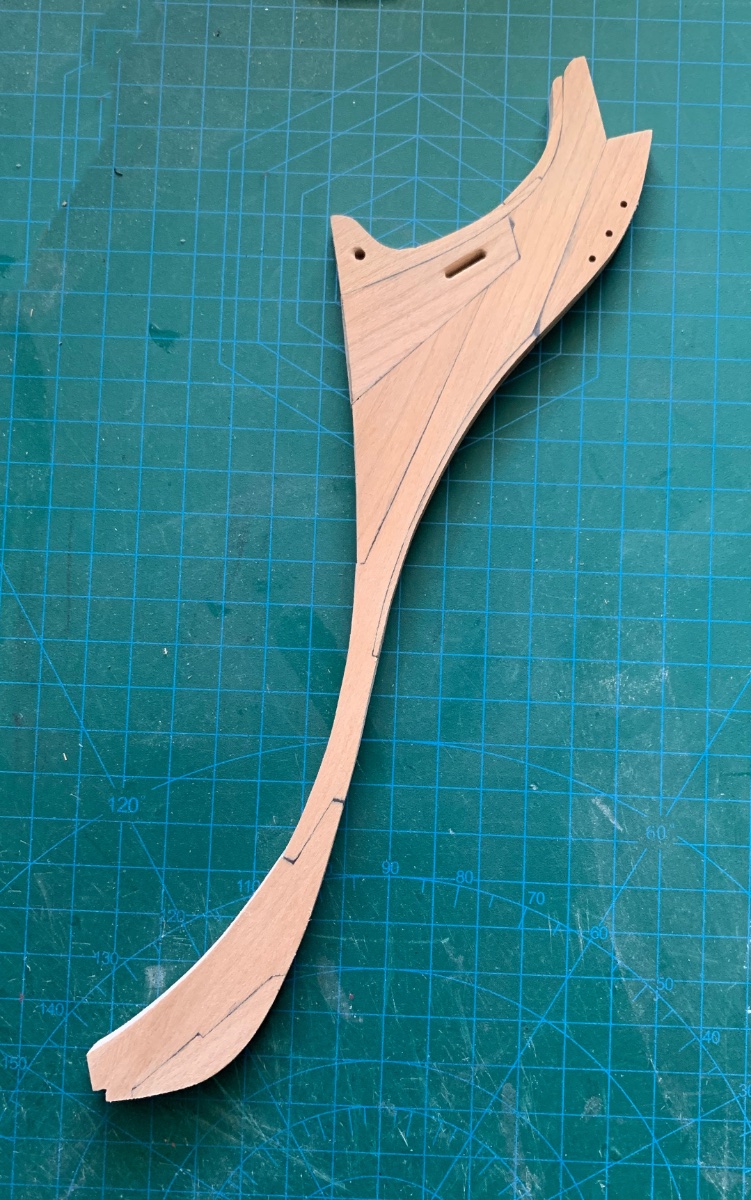
OK, so I couldn't help myself but get a start on EURYALUS. Spent this morning cutting out the bow pieces and fitting them together. All done except for holes and gammoning slot which I will do in the mini mill. this afternoon before mixing some graphite in so wood glue to create the tar lined joints. Used a photocopy template glue to a piece of 14.5" scale cherry, cut with the Dremel scroll saw, cleaned up on the Ozito 3" disk sander then finished by hand with mini chisels, diamond files and finally sandpaper. I know this is held together and to the stem by bolts bit not sure on the positions yet. Also need to better understand if they used iron or phosphate bronze bolts: more research to do. I may go the the trouble of using scale bolts with nuts and washers; either steel (for iron) or brass (for bronze) depending n the prototype.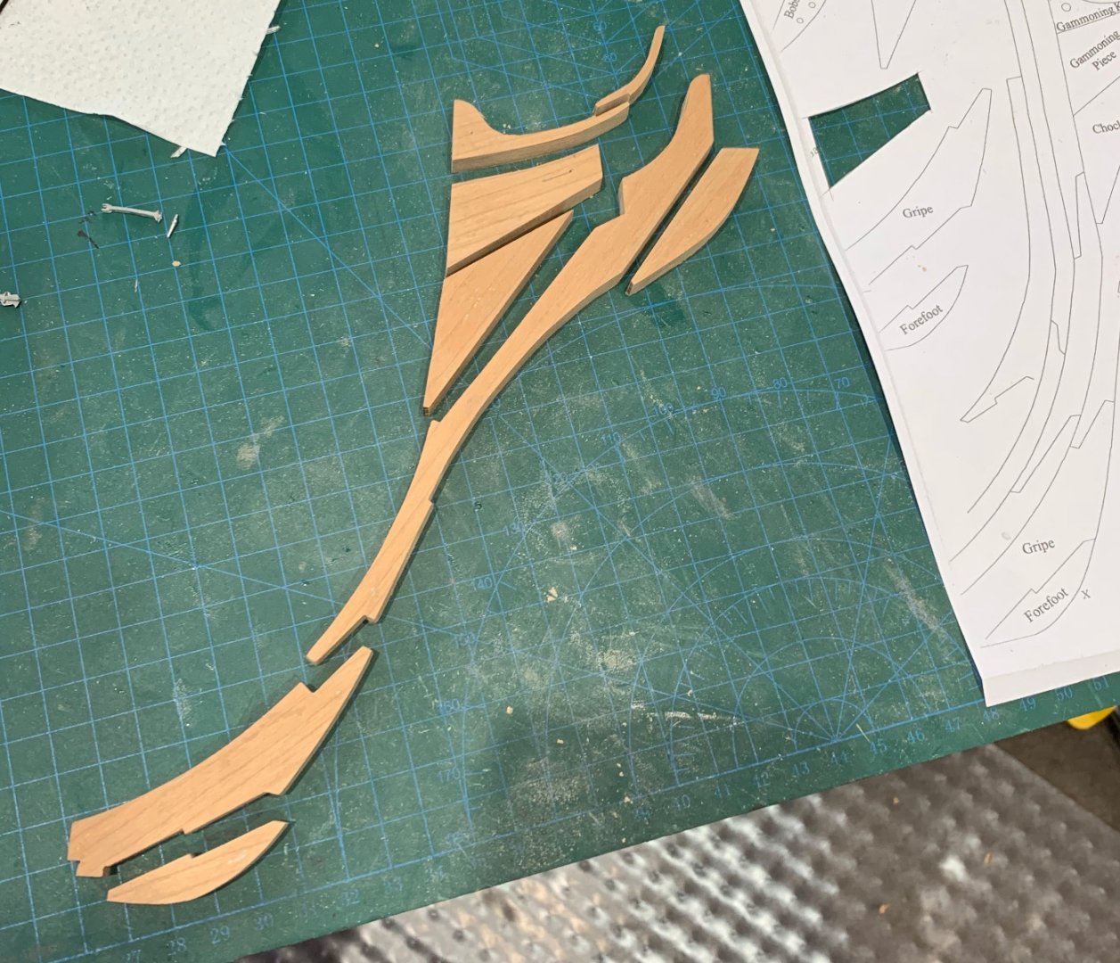
-
EURYALUS 1803 by Peter6172 - 1:48
Peter6172 replied to Peter6172's topic in - Build logs for subjects built 1801 - 1850
Mark. Wasn't sure whether a set of plans and a wood set constituted a kit or not. -
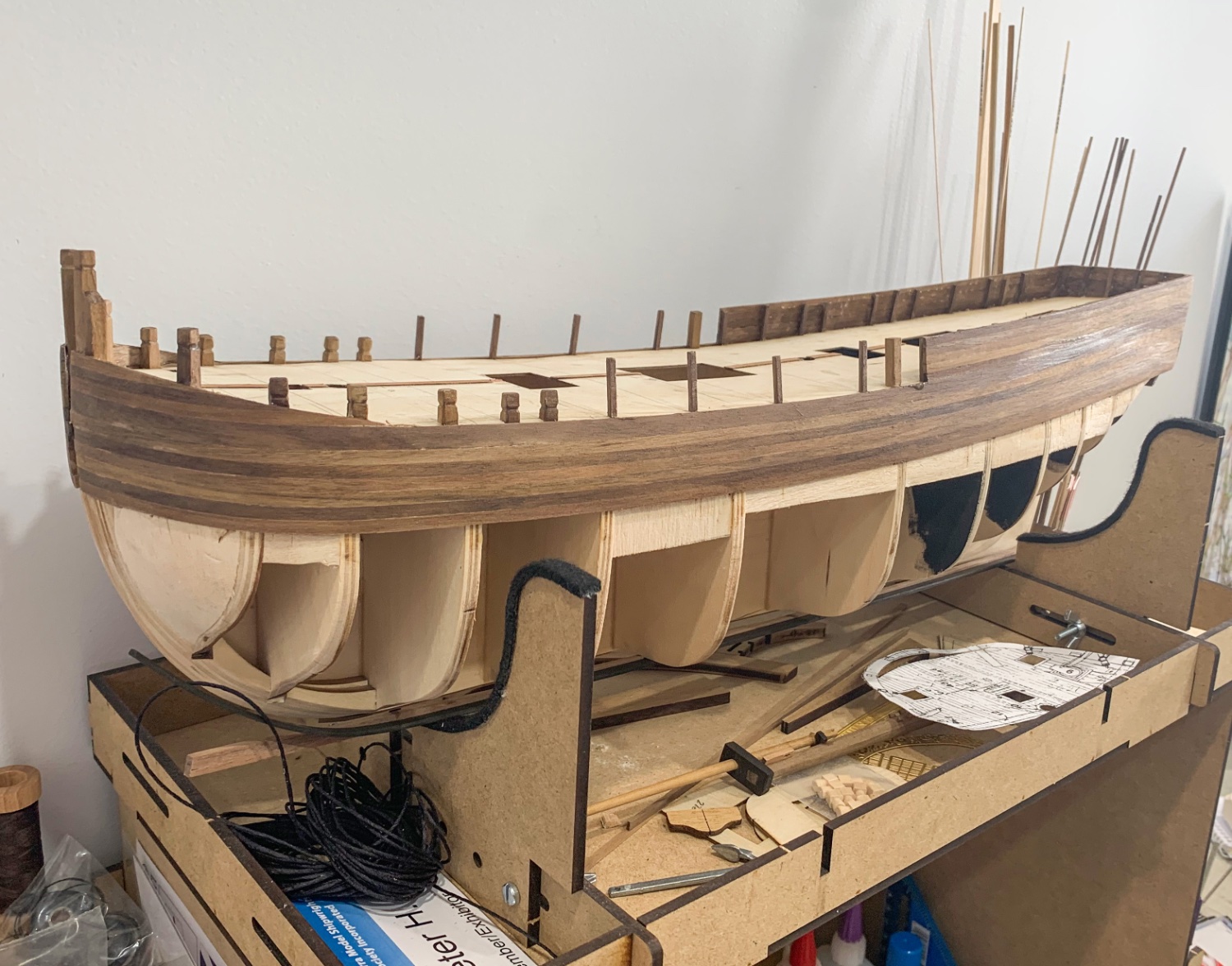
Well team, I hope I haven't bitten off more that I can chew but I have taken over a full frame model of the EURYALUS in 1:48 scale from a long standing member of this forum; Russell H. Russell unfortunately is not in a position to continue building this model so he has offered it to me to complete. Russell has already achieved full framing from stem to the fashion pieces and the fitting of transoms and the Stersom Knee. He has also made a start on fairing inside and out and started laying the first few rows of the ceiling from the keelson. Port side is full frame, Starboard mostly framed; gaps for viewing internally. The plan is to fully plank Port side and only partially plank Starboard side (same for the decks. Russell hasn't worked on the model for nearly 2 years so things have settle a little. First step will be to ensure full frame alignment and secured them before continuing the journey. A little damage has occurred with one Of course this will mean that THUNDERER will be put on the back burner as I will not have the space to build two 1:48 warships concurrently. Time to check out the other EURYALUS builds on the forum.....
-
Thank you for the tip Yves. It's under the Christmas tree at present so I will have to wait before I can pull out the parts and do actual test fitting. The current figurehead may not be the correct size as I based its overall dimensions on the figurehead in the AOS-Bellona book. Once I have the parts in close proximity, I can then scale and reprint the figurehead if required as it seems a little large at present. Then gain the Bellona is a large ship even in 1:48 scale.
-
Allan, you are correct. I feel that Yves has used the thickness of the stem material without taking into consideration that the stem is tapered going forward from the bow. I did a rough calculation and specified 7mm (based on the drawings in AOS-Bellona), however the designer has only allowed for 5mm at the knees opening to 8mm at the feet. I am quite comfortable shaving a little off Zeus' knees/stem to get them to fit together.
-
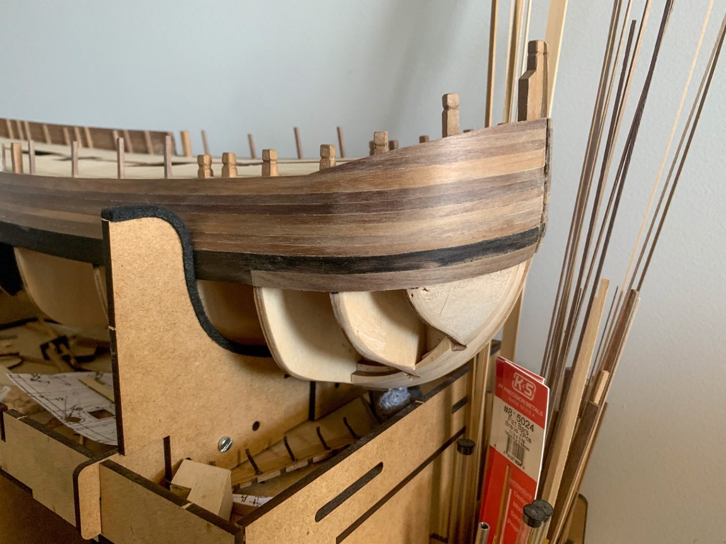
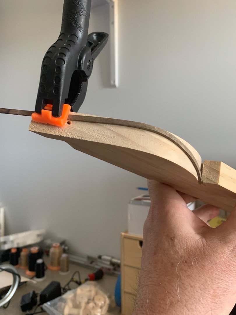
Not happy with the lie of the second whale and how much material I had to remove to fair it so I cut out the bow section and spiled in a new plank. Fits much nicer. By the way, when I say smile I mean steam and bend the plank on a curved former but also bend it in two planes to mimic a spiled plank as demonstrated with th next plank to go in under the whale. I do have to add additional clamping to assure the plank lies flat the full length of the former.
-
My first print of the THUNDERER figurehead. I have put it on the bow of GREYHOUND (1/100). Unfortunately the shield and crown did not print well as the thickness was too small so I will have to go back to the designer to get those parts bolstered.
-
Work on BOUNTY is stilll progressing (slowly). The second whale is in on the Starboard side but it needed an awful amount of sanding. Th ePort side second whale is being steamed and bent a little differently to put in a compound curve to simulate a spiled plank - a bit difficult to photograph while clamped up but I will see how it comes up after clamping
-
First whale installed both sides. Whales have been stained with Japan Black. Unfortunately the wood is so dense it didn't stack in so I will have to touch up after sanding. The topside planks are still awaiting their post sanding sealer sand.
-
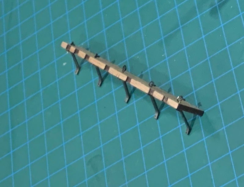
Working on the BOUNTY's channels while contemplating GREYHOUND's next steps. The kit supplies two top mounted wood knees for each channel, however AOS shows undercount angle brackets lined up with each of the ring bolts so that's what I am attempting. I used 0.5mm hard brass wire for the eyes and the rings and 1/32 x 1/16 brass strap for the brackets. Its a little tedious but if its authentic to prototype then needs must.
-
BOUNTY has been planked to the whales and given preliminary sanding and a coat of sanding sealer.

-
I have placed a temporary hold on BOUNTY works as I examine a couple of disposed of HMS GREYHOUND partial builds to see that can be done with them. Image 1 is the work in progress from a previously partial planked hull. Had to remove planks and decks and a couple of bulkheads and start over with a new scratch built deck. A twisted false keel required a sturdy build frame. Image 2 shows the progress of Hull 1 against the previous owners planked Hull 2. I considered cutting everything off along the main deck but the hull retains the unmodified Bulkeads 9, 10 and 11 and has the appearance of an early pregnancy. I think that one will go to the bin.


-
Planking of BOUNTY is well underway with the transom completed, the sheer strakes installed and the first 5 rows of planks. 2 more rows plus the 5 rows of bulwark planks to be done still. As I am getting close to the whales, they have been bent and will get a soak in Japan Black stain. I will sand the sheer, 7 rows of planks plus the Bulwark planks before installing the whales.
-
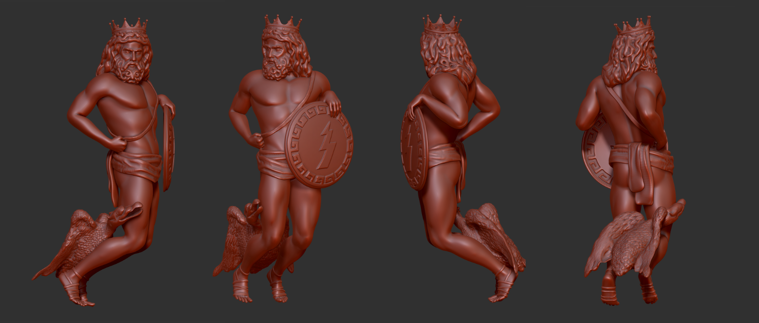
Final 3D model waiting to print. Have been in contact with one resin printer in Canberra but communications seem to have been broken. It seems the local crew may have difficulty printing this model 90mm x 40mm x 30mm?

-
Progress is still being made on BOUNTY. I have just about finished all the stanchions and bollards on the STBD side and all the stanchions on the PORT side. I have also started planking the transom. Won't be long before the first hull plank is laid starting with the sheer plank. NORFOLK has just been matt Varnished: still wet which is why she's a little shiny.

-
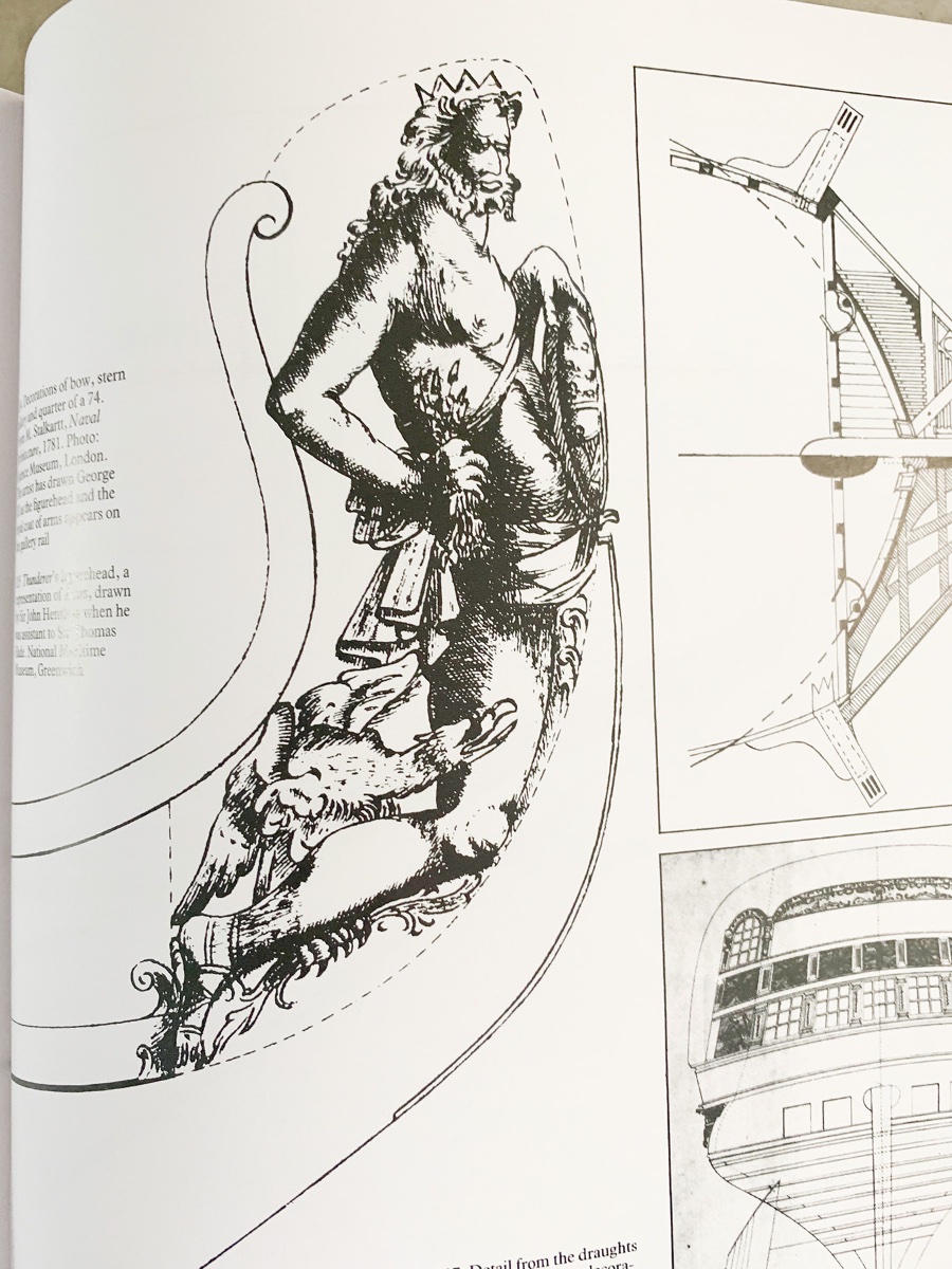
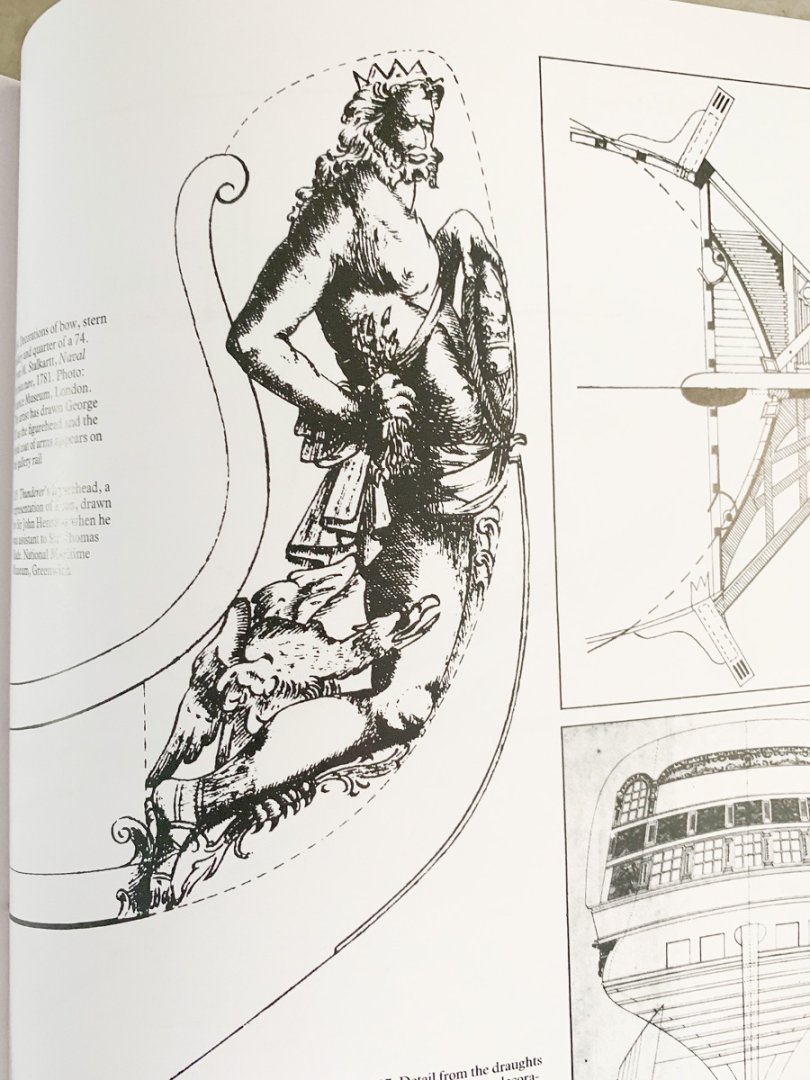
Allan, THUNDERER to which I refer (from Dodds and Moores book) was launched in 1760 and lost in a hurricane in 1780. I was not aware that another THUNDERER was launched 3 years after the loss of the first. The ZEUS figurehead is shown in the Dodds and Moore book. The RMGModel is a builders model of the THUNDERER/HERCULES. Both THUNDER and HERCULES were ordered on the same date (15/7/1756) however HERCULES was built at Deptford and commenced 2 months earlier than THUNDER who was built at Woolwich and launched a full year later. The builders model was made before the design was approved and the order for the ships made. These models were used to loft the ship, it was at Deplored first before being transferred to Woolwich. The figurehead on the ships model would be a modellers interpretation at the time as the ZEUS figurehead was created at Woolwich by John Henslow reputedly on the spot during the construction of THUNDERER (refer Dodds and Moore).
-
Anyone interested in my designers details, he's on CGTrader 3D Projects and FIVERR. He can be directly contacted on What's App at +94713926123 or email at gayan220@gmail.com