Ferrus Manus
-
Posts
1,407 -
Joined
-
Last visited
Content Type
Profiles
Forums
Gallery
Events
Everything posted by Ferrus Manus
-
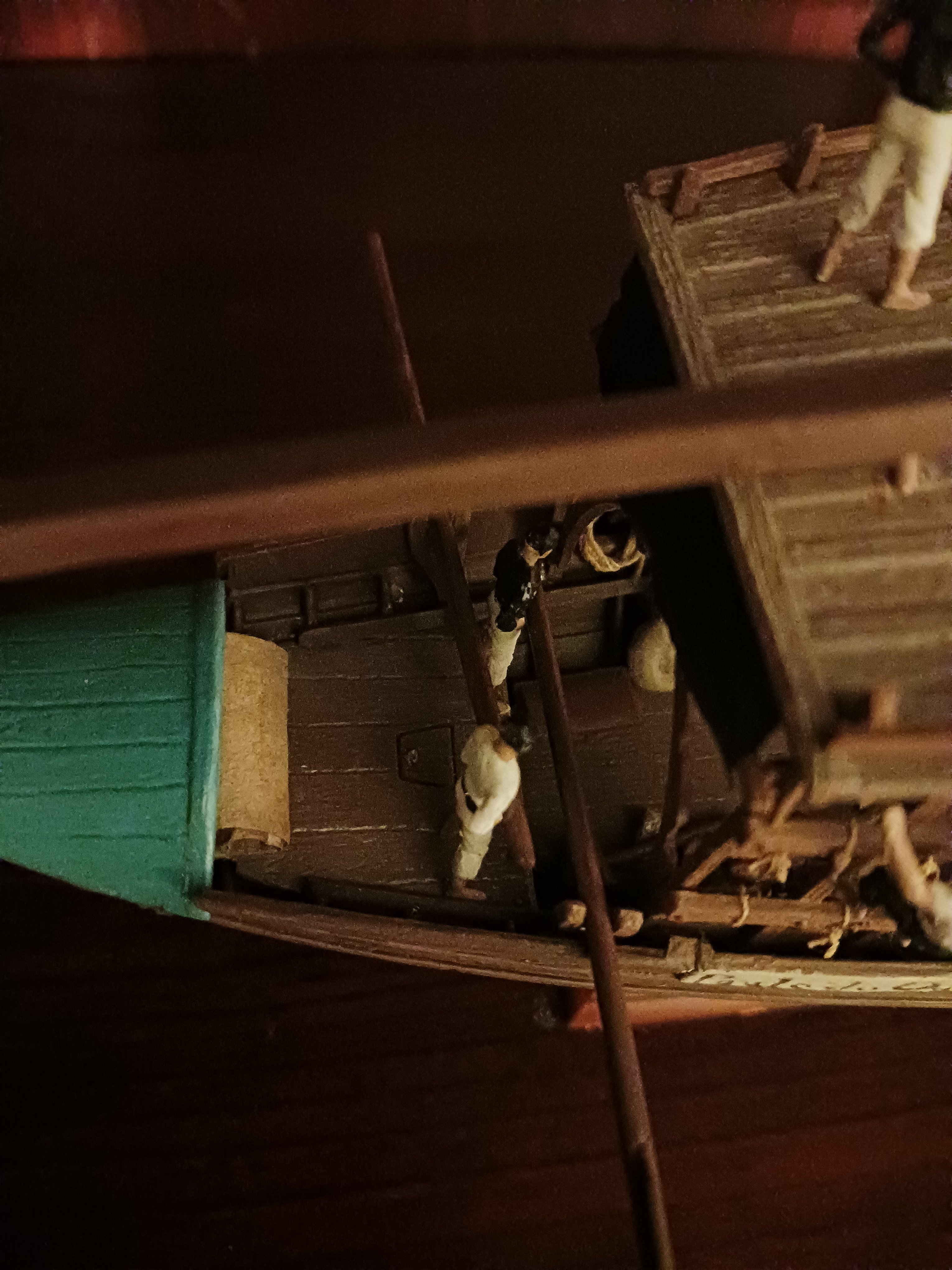
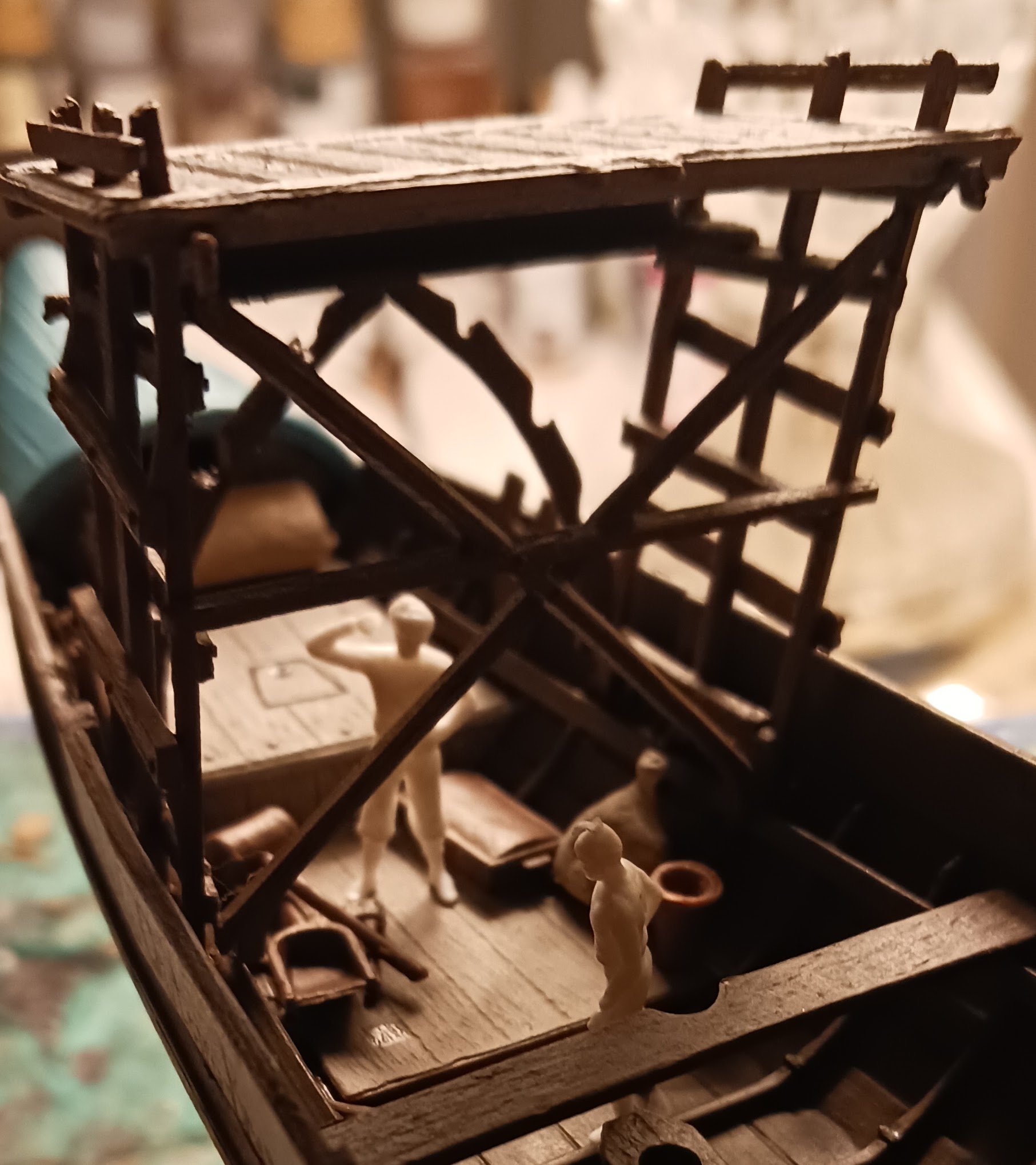
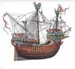
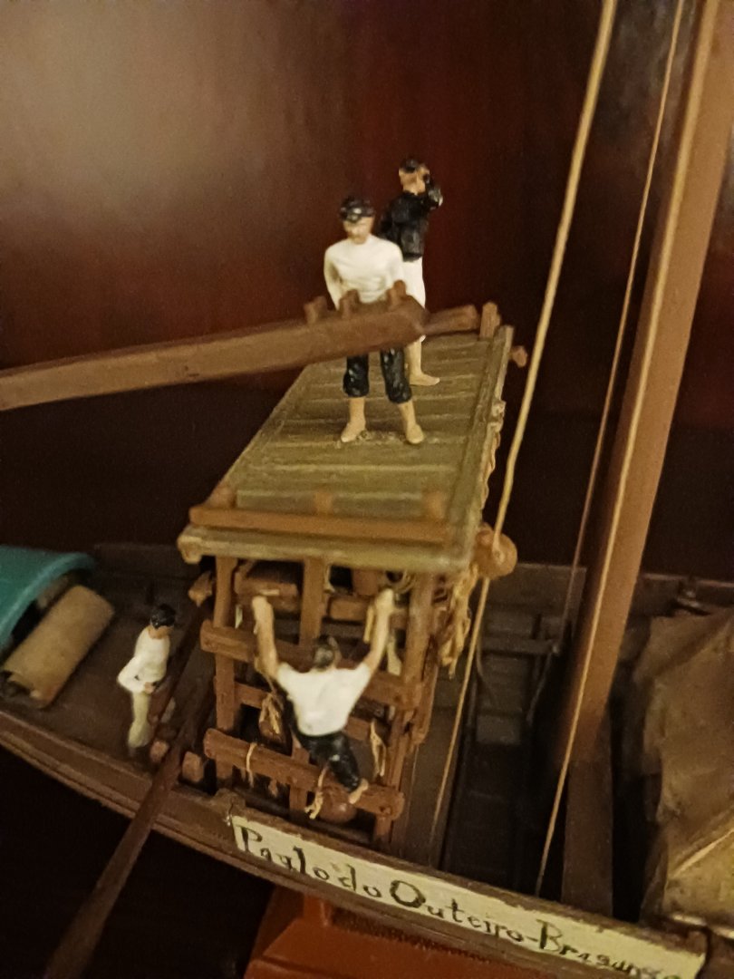
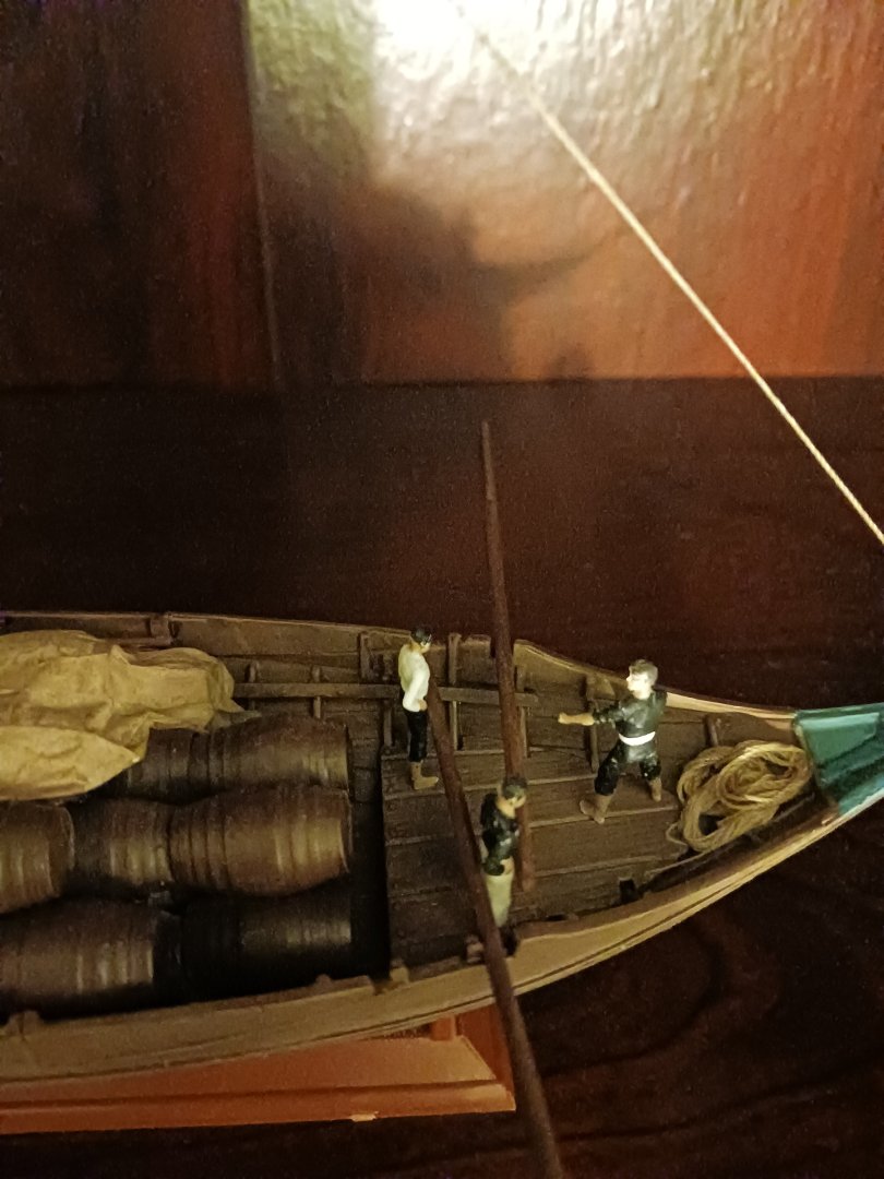
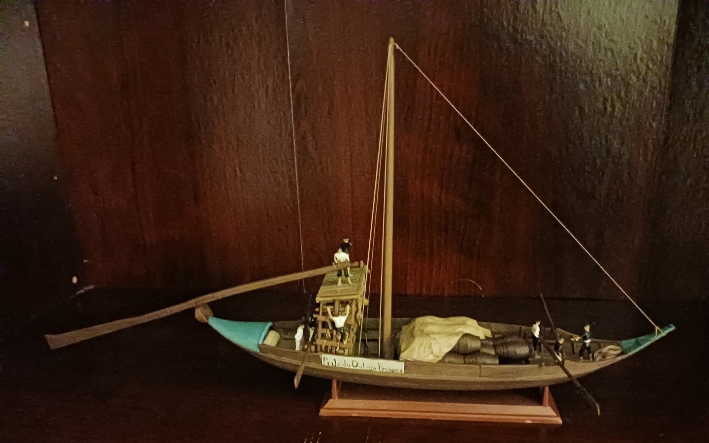
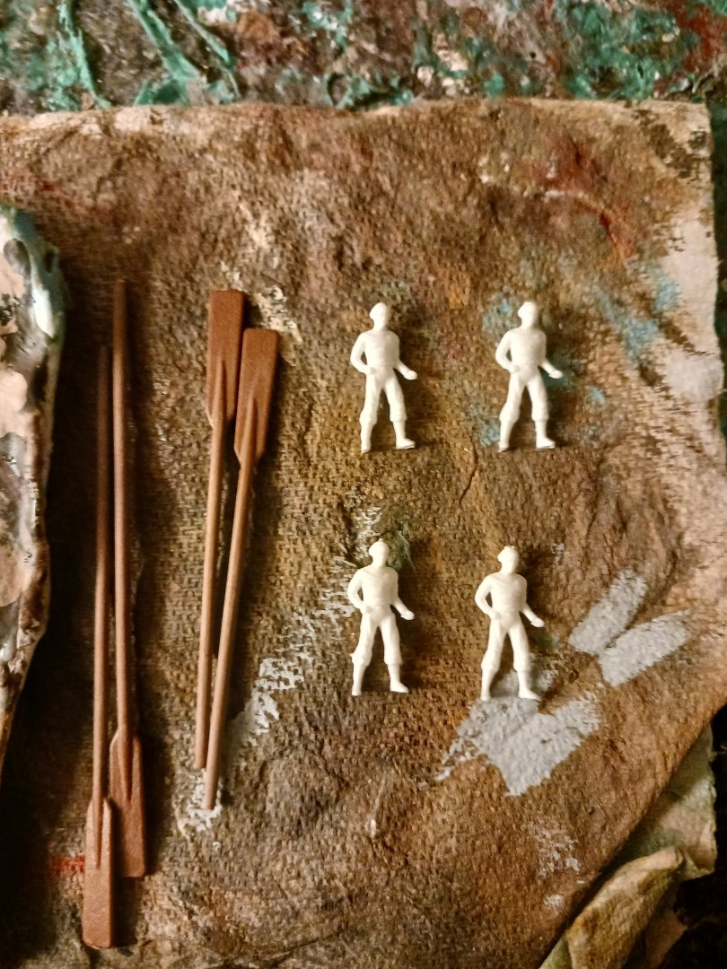
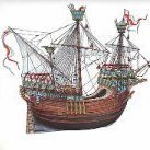 The boat is officially crewed. About 5 or 6 years ago, I did a model of an English galleon (which was released as a small and equally inaccurate modification of their Spanish galleon) which was a terrible kit, but taught me quite a bit about how the core aspects of ship modelling work. That kit came with crew figures that were in about 1/75 scale that remained unused. I cleaned 8 of them up, painted them to look like Rabelo boatmen, and put them on the boat in accordance with historical evidence. They need a bit of paint cleanup from consistent handling, as does the rest of the boat. The man at the very fore of the boat, who will be hauling on the bowlines, has not been glued into place. I might recruit some more help for the fore oars, which are considerably longer than the aft. The boat as she is today:

- 17 replies
-
- 1
-

-
- barco rabelo
- 1/75
- (and 2 more)
-
Sail feedback request, Mondfeld method
Ferrus Manus replied to travis's topic in Masting, rigging and sails
Personally, I swear by silkspan. You can buy it all over the United States, and I'm sure eBay or Amazon sells it. I have used multiple different thicknesses of silkspan and never, ever had any issues even when the material was wet. The only tears I have had using silkspan sails were completely my fault and not that of the product, and were pretty easily fixable because they were small. Making a scale-accurate sail never takes me more than about a day. You can even replicate things like tarpaulins using silkspan- really any cloth product present on a real ship can be accurately represented. -
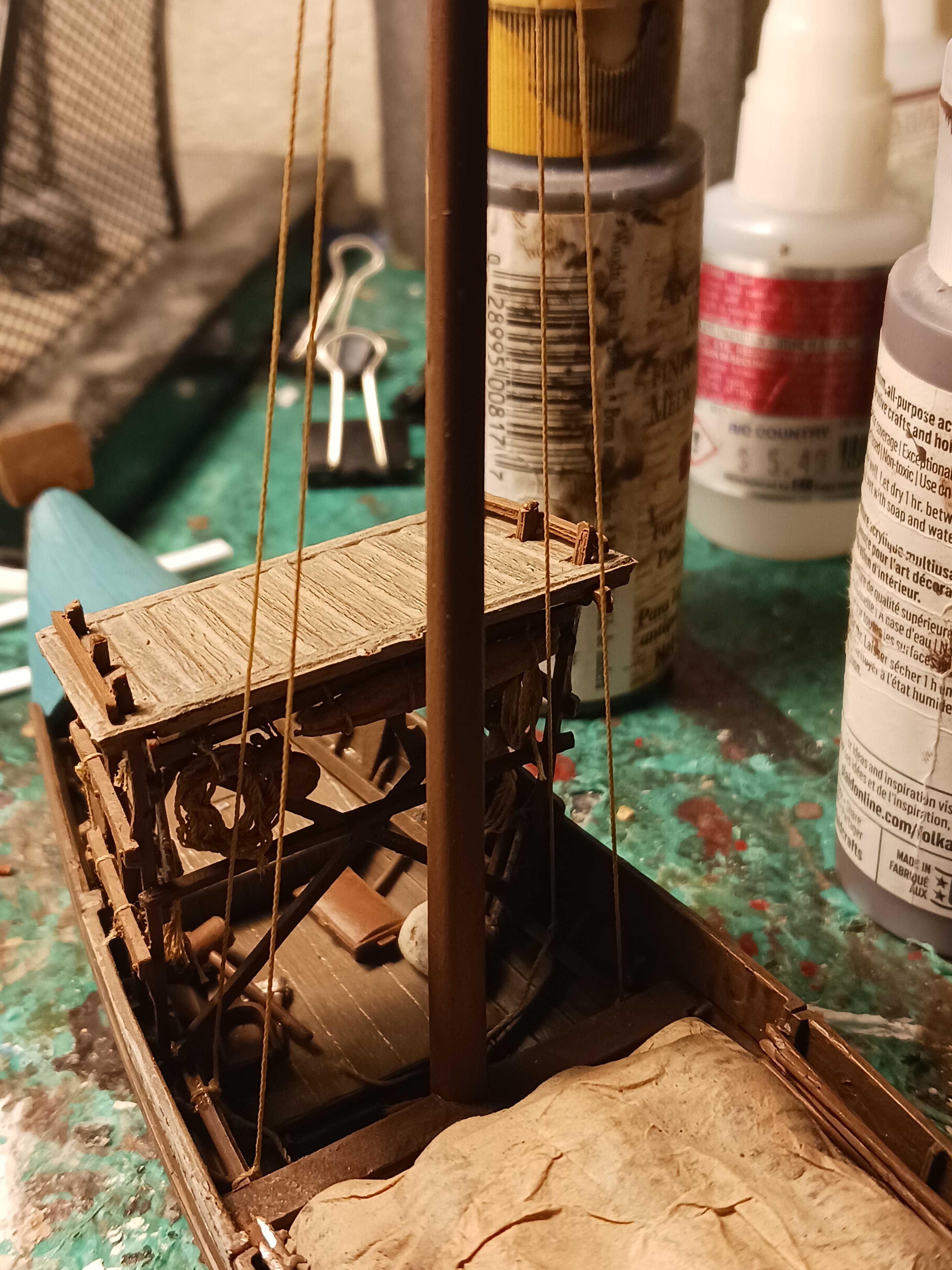
I've done a bit of work on the Rabelo boat in the last few days. I have gotten a few things ready for the addition of the crew, for one thing. I've also added some of the last remaining deck details. I've also gotten the mast stepped and the relatively simple standing rigging completed. Realistically, the boat probably would have been on the upriver journey at this point, as evidenced by the fact that it has its rig. I wanted to depict it with the sail just for completion's sake. From what I gather, they didn't go upriver empty, but instead took empty wine casks with them.


- 17 replies
-
- 3
-
-
- barco rabelo
- 1/75
- (and 2 more)
-
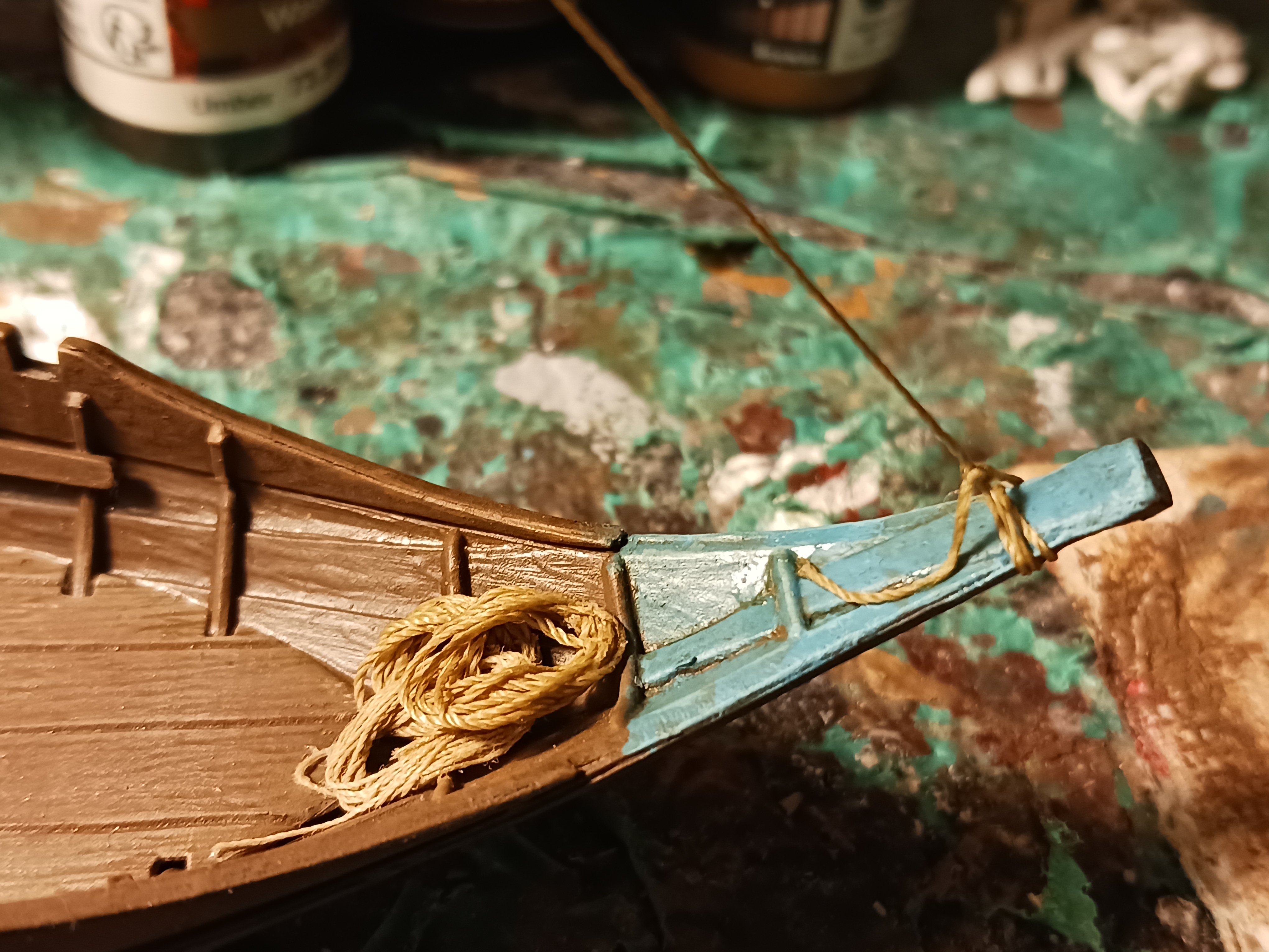
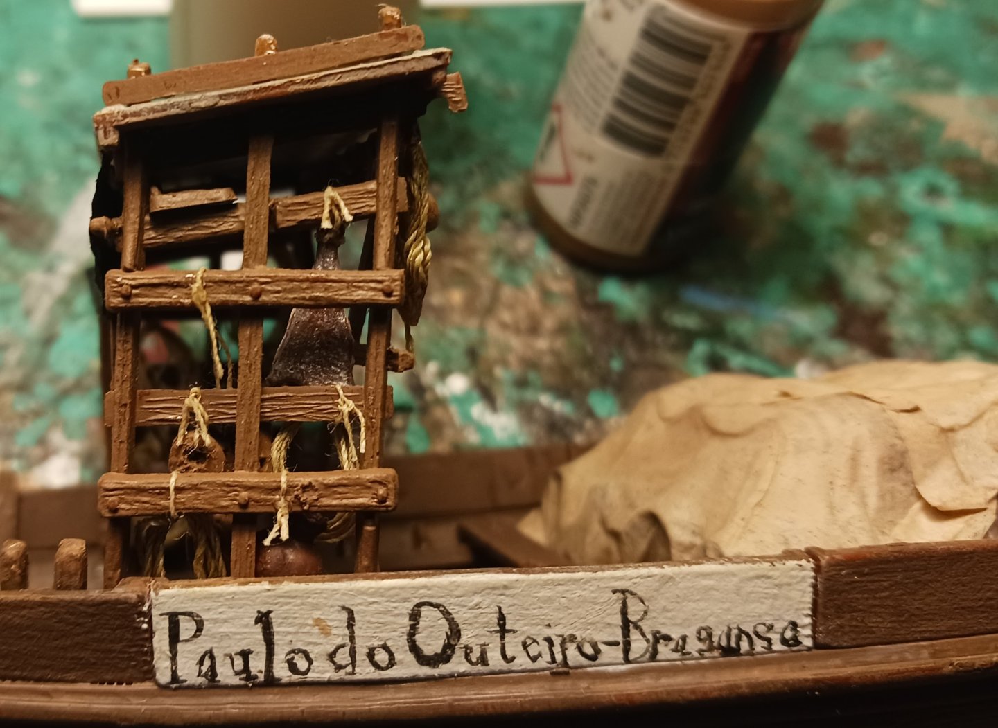
The apegadas is complete, with the exception of the ropes that will be directly used to control the steering oar. Happy New Year!

- 17 replies
-
- 3
-
-
- barco rabelo
- 1/75
- (and 2 more)
-
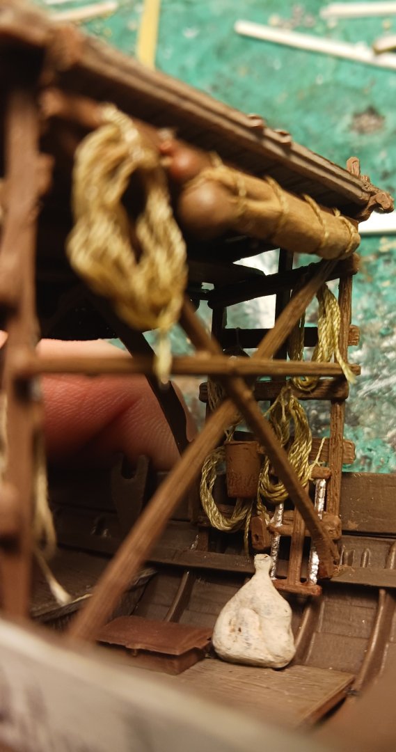
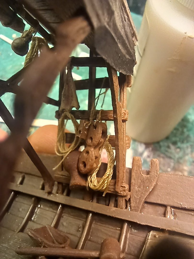
Happy New Year to everyone who visits this build log. My last bit of work for this year will be to fill up the apegadas with rope and equipment. The rest will wait until next year.
- 17 replies
-
- 1
-
-
- barco rabelo
- 1/75
- (and 2 more)
-
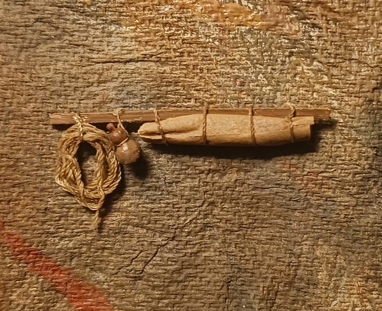
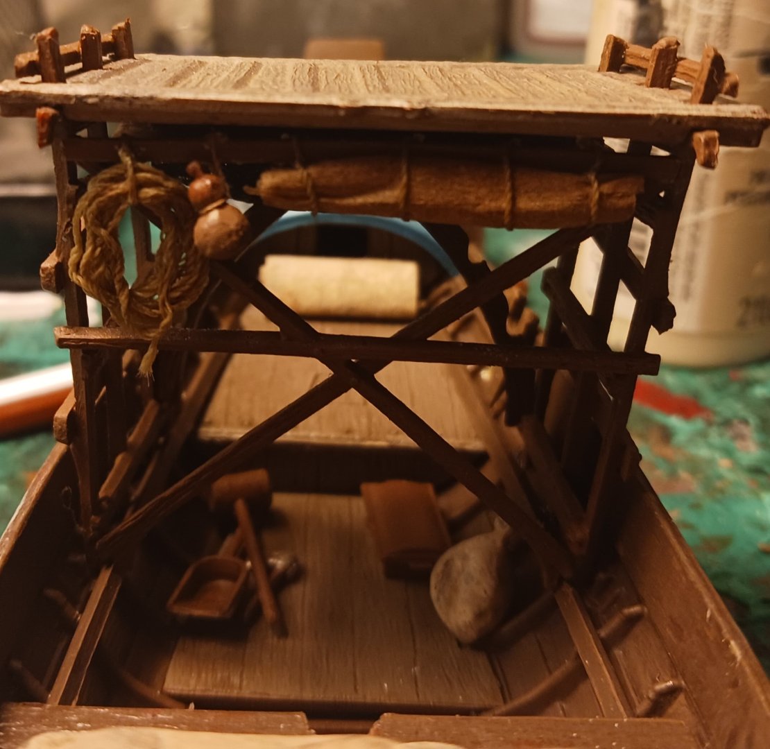
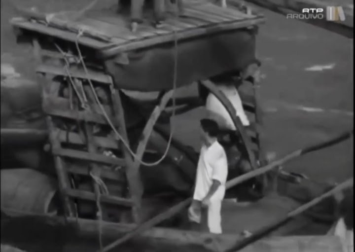
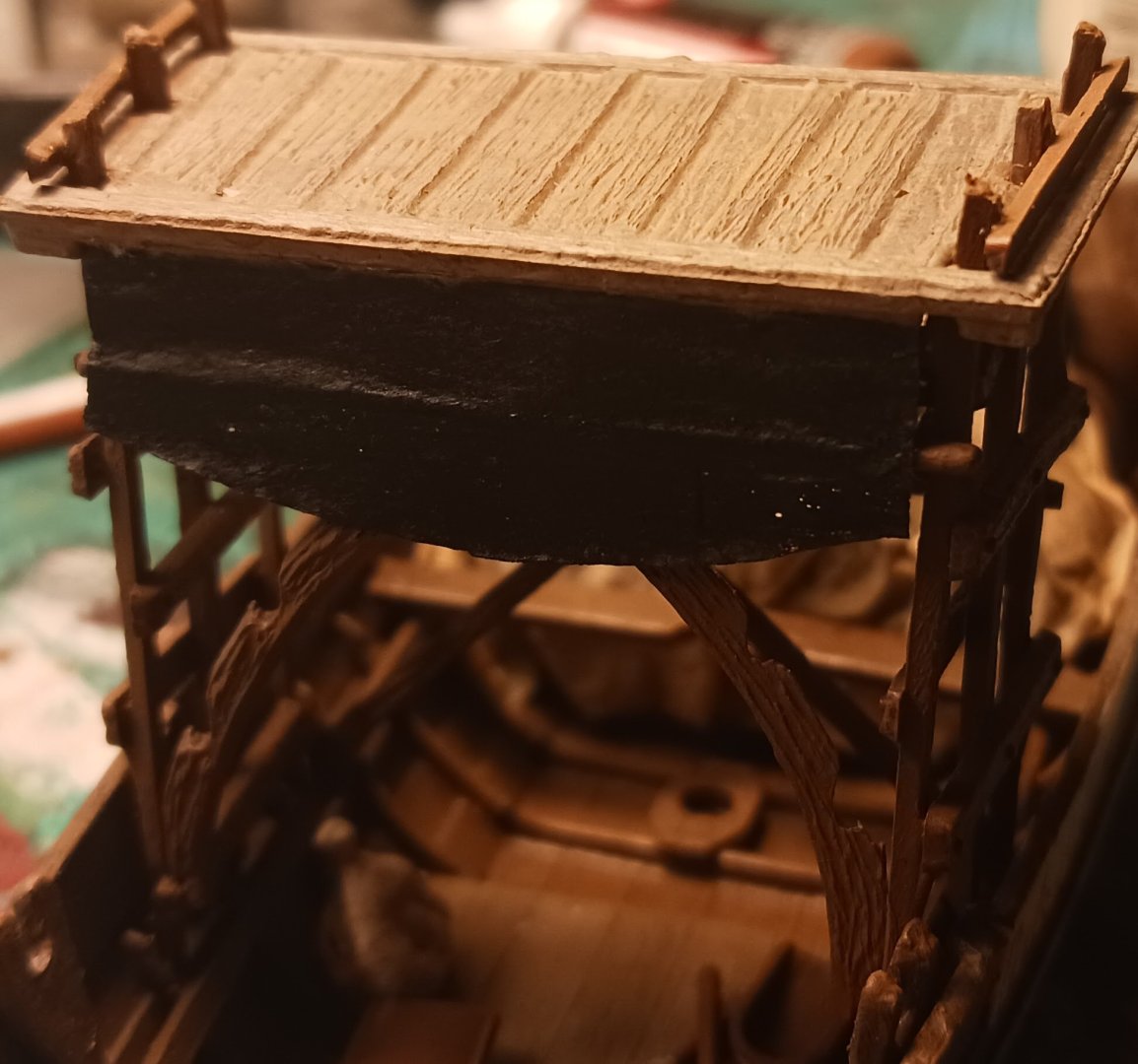
I did a bit more work on the Rabelo today. Firstly, I made and installed a small timber at the top of the apegadas with some things tied to it. This is consistently visible in pictures, even of the Rabelos with tall platforms. Secondly, in some footage I saw, there was a black cloth attached to the back of the platform, which I attempted to replicate. This might have been some sort of awning.
- 17 replies
-
- 4
-
-
- barco rabelo
- 1/75
- (and 2 more)
-
I made my tarpaulin by dunking the silkspan in diluted brown paint and then diluted white glue, and put it into position. I then repainted it with a canvas color. You're going to want to look at how Joelle does his.
- 17 replies
-
- 3
-
-
- barco rabelo
- 1/75
- (and 2 more)
-
Special thanks to @madtatt for teaching me how to make tarpaulins.
- 17 replies
-
- 1
-

-
- barco rabelo
- 1/75
- (and 2 more)
-
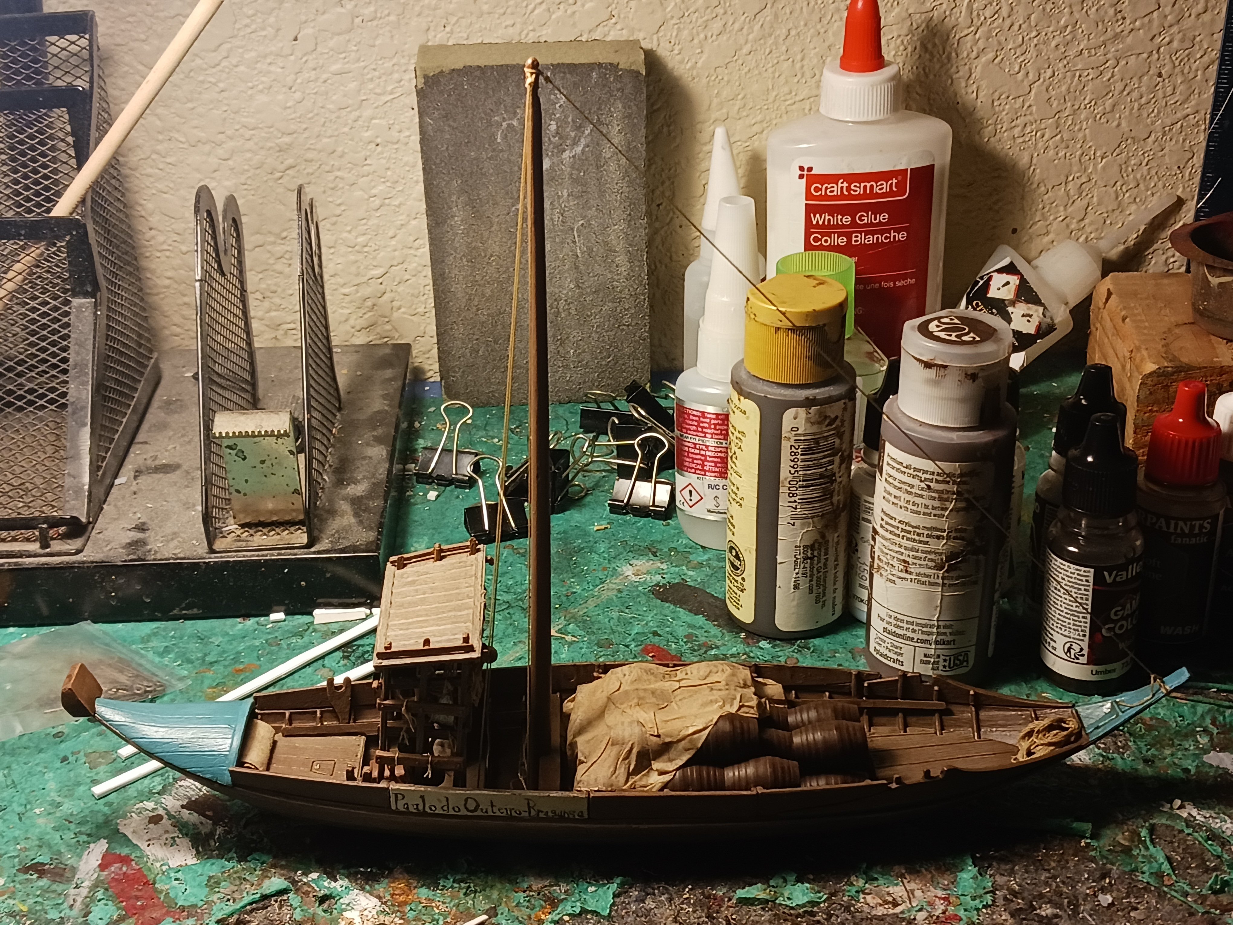
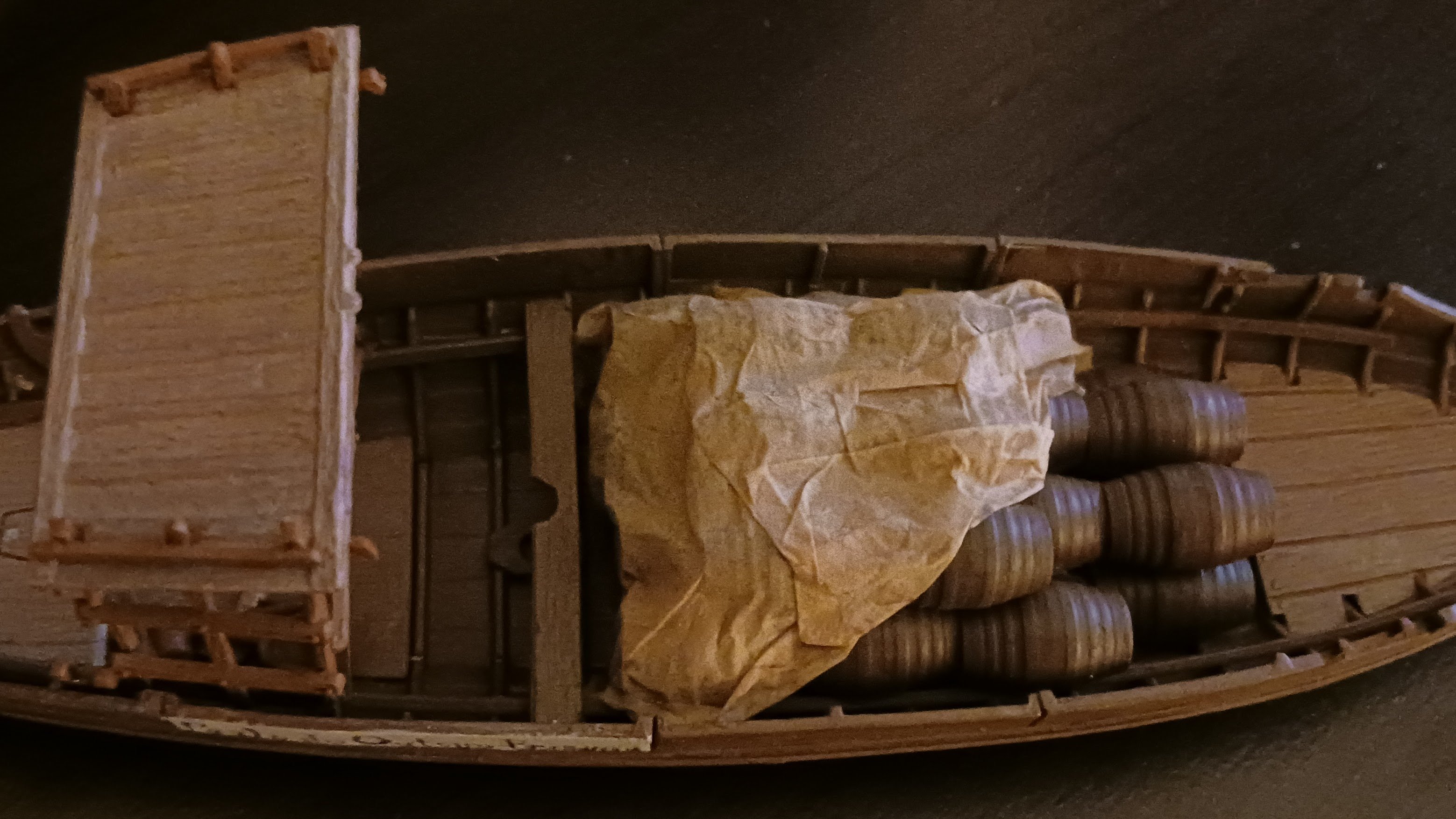
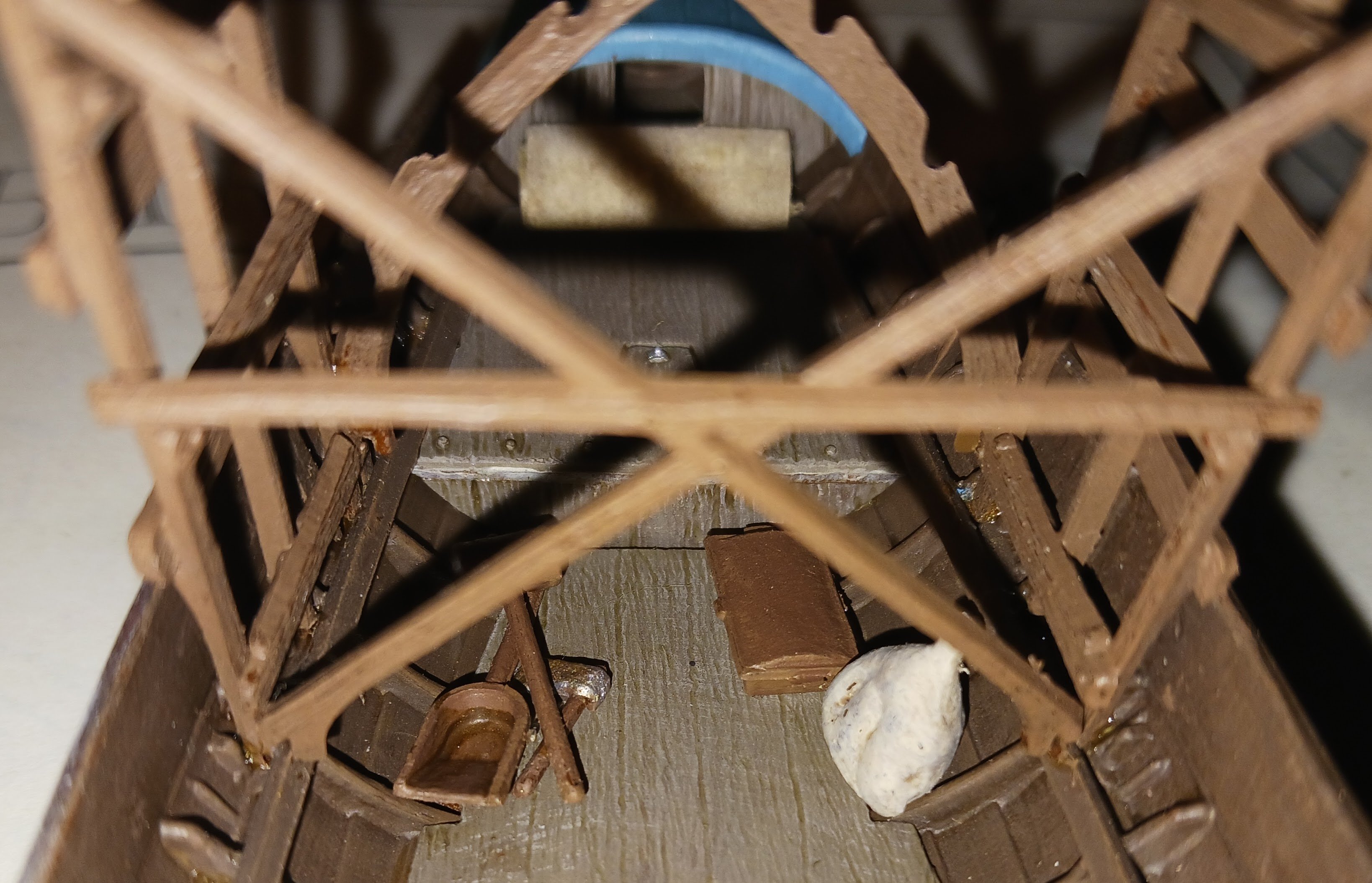
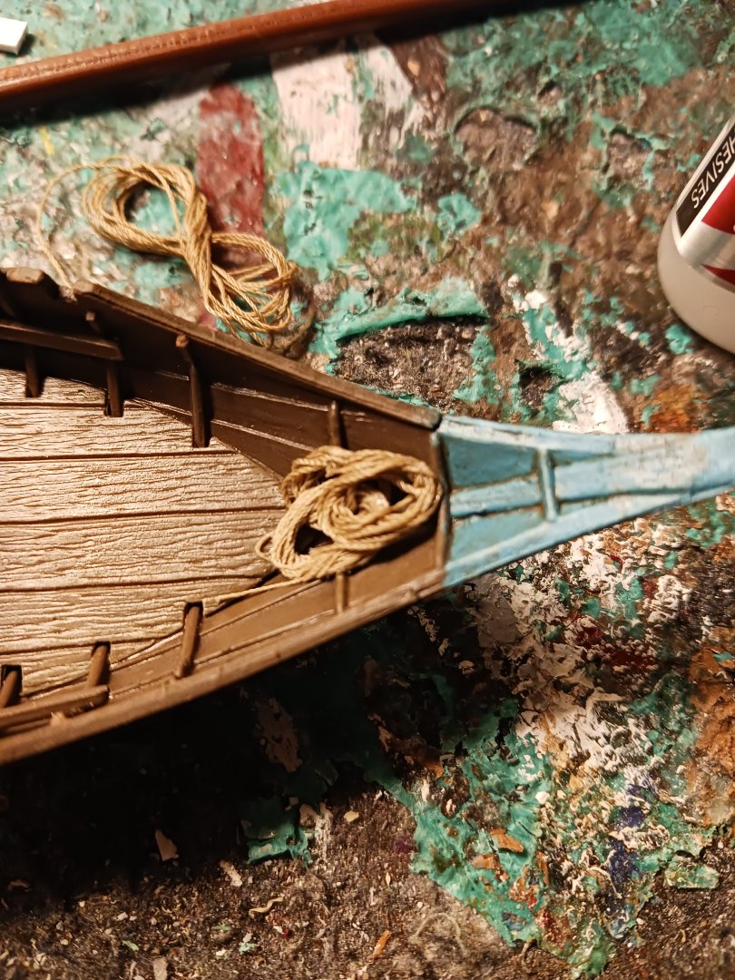
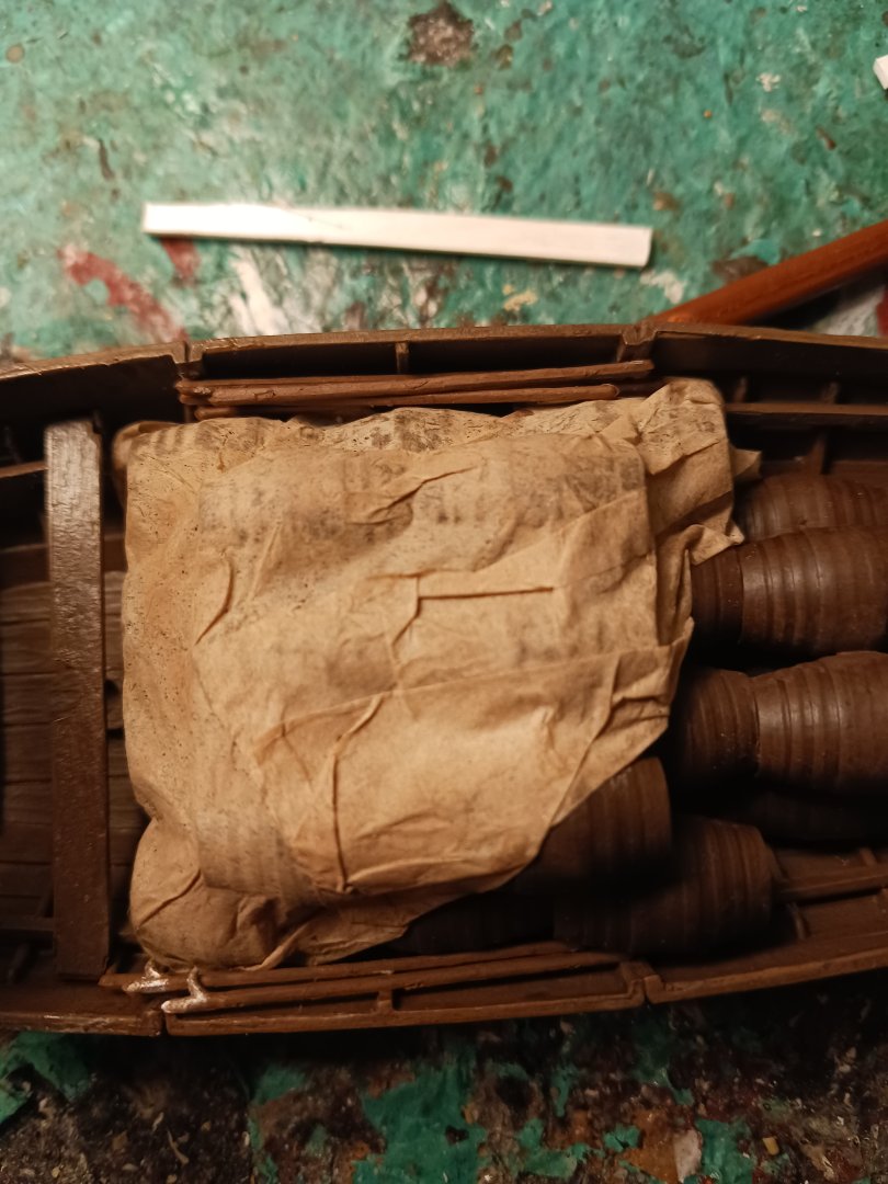
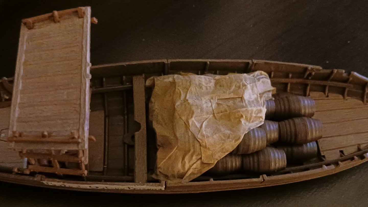
The Rabelo now has its payload, that being 32 pipas ("pipes" or casks) of Port wine from the Alto Douro vineyards, bound for Vila Nova de Gaia. The casks are partially covered with my first-ever attempt at a tarpaulin, which is folded back so you can see them. If there weren't enough things in the cargo section already, there will also be a bundle of poles for the aft awning, as well another bundle for the poles and boat hooks. The men would intentionally beach the Rabelo for the night on a sandy part of the river (few and far between) and in the morning they would pole the boat off of the sand and back into flowing water. That doesn't include the two large planks they would have stowed lengthwise onboard the ship for offloading the wine: They would also often sail down the river with no rig, as the river's momentum was often sufficient to keep them in motion, sometimes supplemented with rowing. They would then set the completely removable mast and sail at either Porto or Gaia for the return journey. Remember when I mentioned the need for the removable planks to increase freeboard? The reason why those were necessary is that these men packed the boats so full of wine as to be dangerously overloaded. The rest of the equipment has yet to be stowed under the apegadas.
- 17 replies
-
- 5
-

-
-
- barco rabelo
- 1/75
- (and 2 more)
-
@JacquesCousteau I revisited your Canoa de Rancho just now, and immediately recognized just how similar these boats were to the Rabelo boat I'm working on now. Truly, convergent evolution does exist in shipbuilding!
- 17 replies
-
- 2
-
-
- barco rabelo
- 1/75
- (and 2 more)
-
If you don't mind me asking, how in the world do you make tarpaulins like that? They are the most realistic I have ever seen by a large margin.
- 211 replies
-
- 2
-
-
-
- Russo-Japanese War
- Mikasa
- (and 2 more)
-
That all looks reasonable for a fishing boat. There is a hatch for the fish, and a winch for the nets. Google image searches for the vessel in question should suffice for you to figure out the rigging.
- 38 replies
-
- 2
-
-
- Fischkutter
- Laser Creation World
- (and 1 more)
-
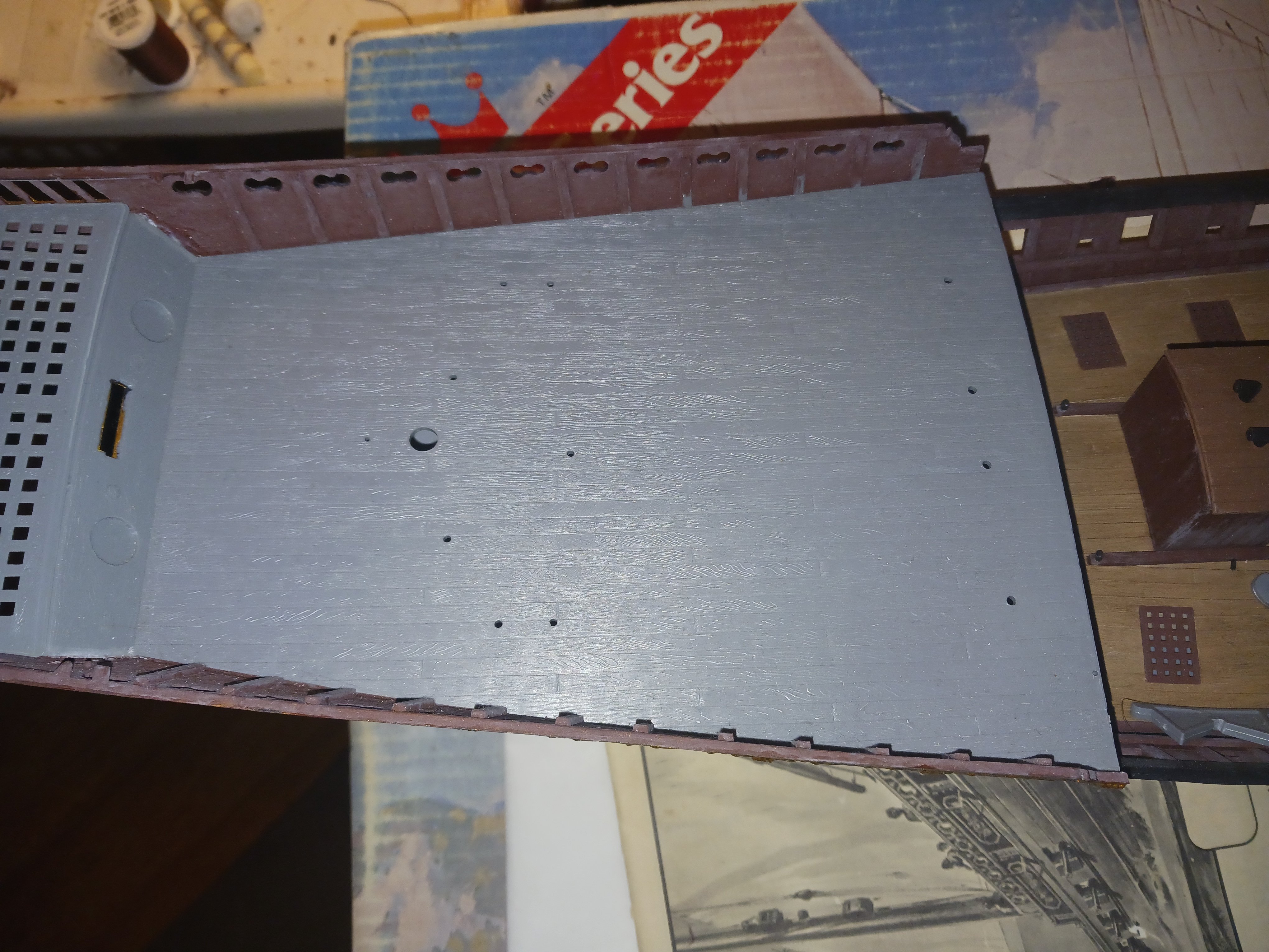
What isn't shown is the 50 eyebolts I made from steel wire, and put in a small plastic bag. They will be needed for the gun rigging.
-
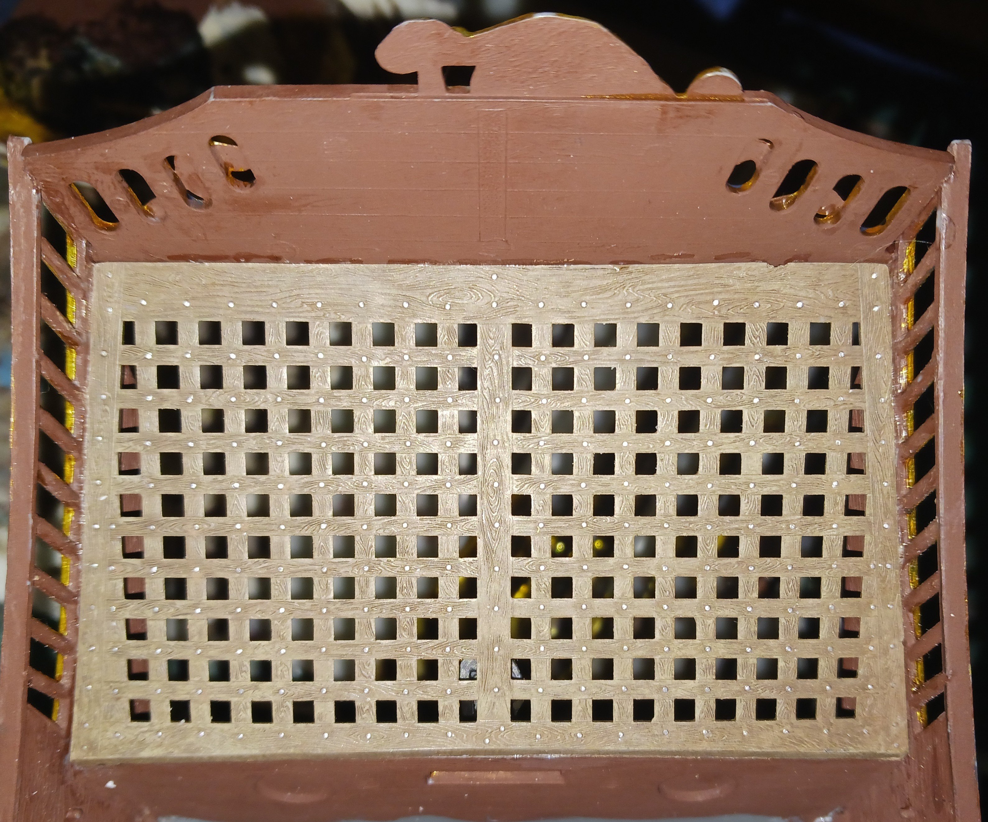
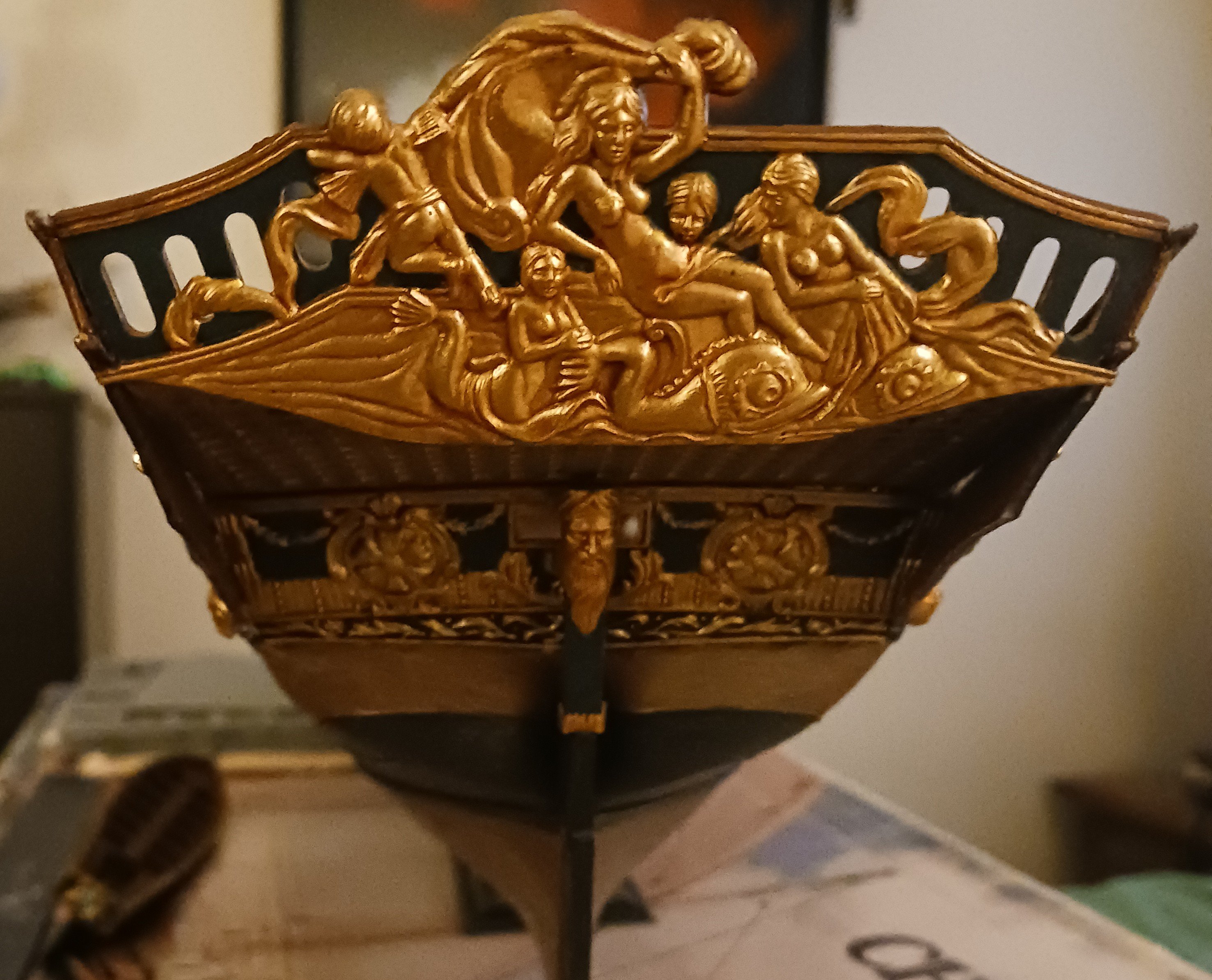
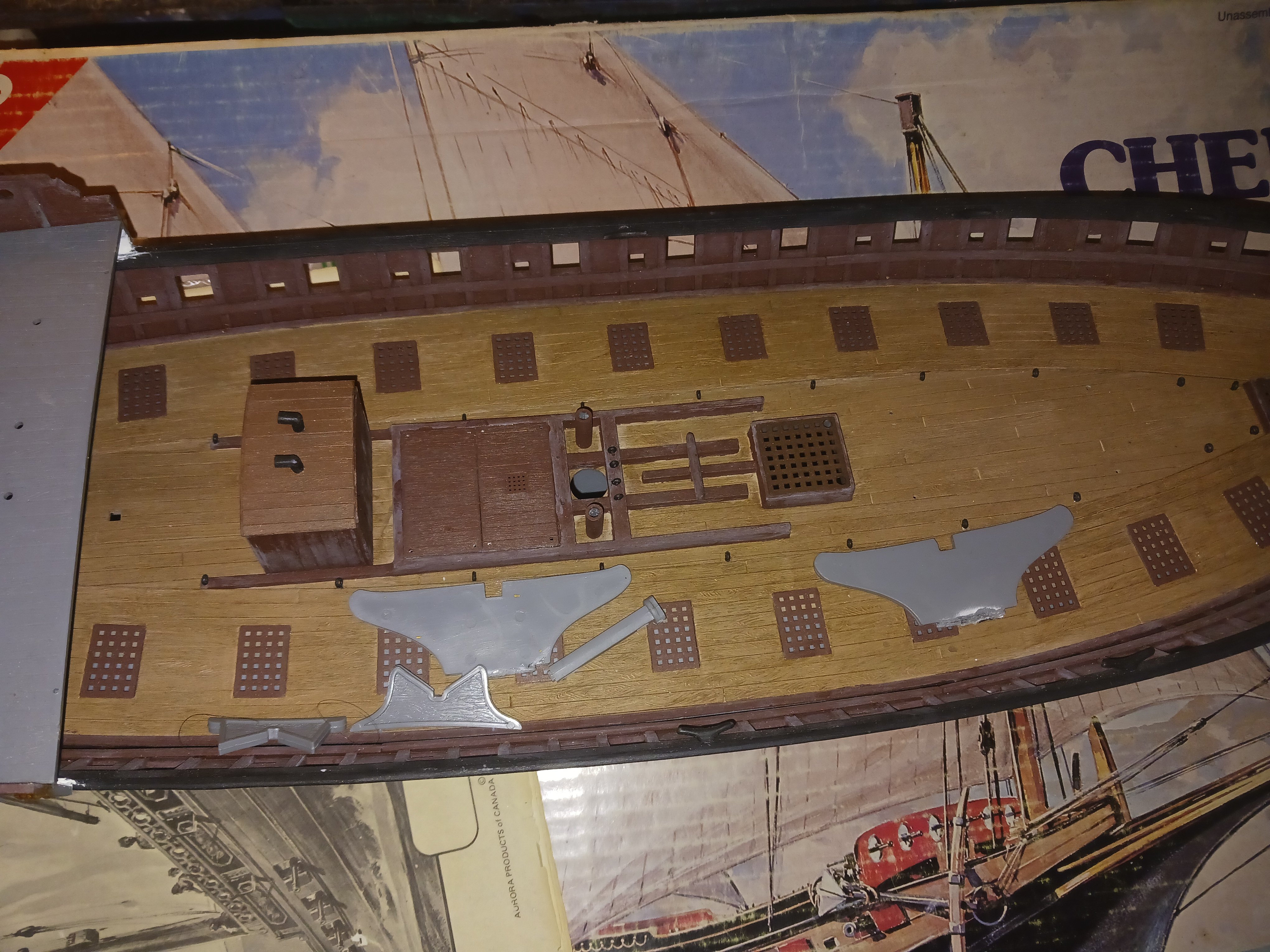
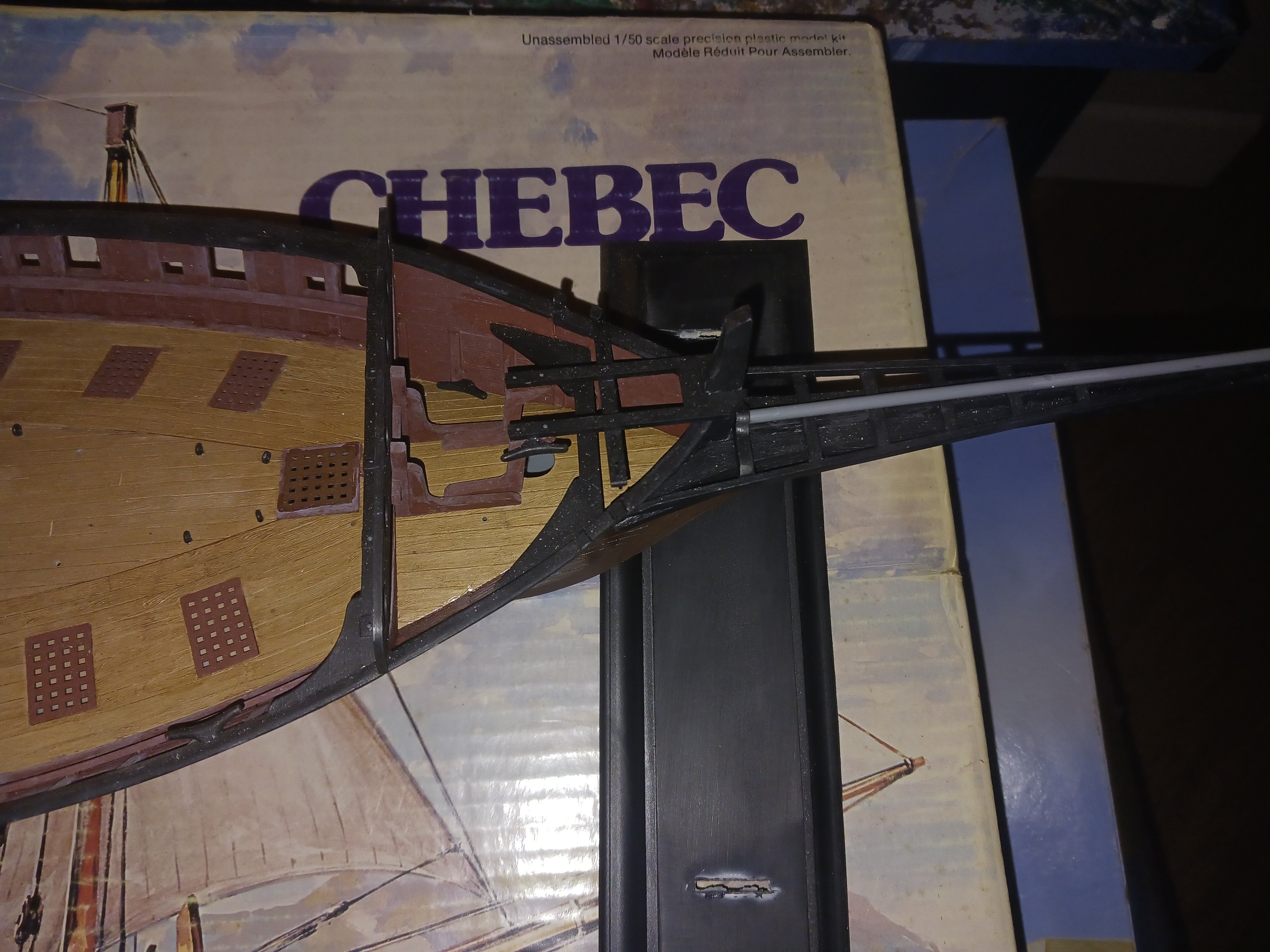
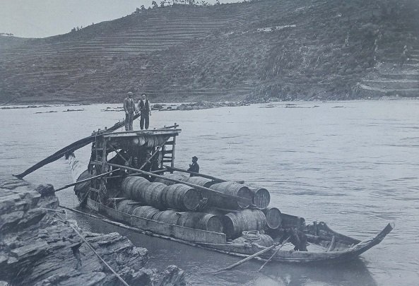
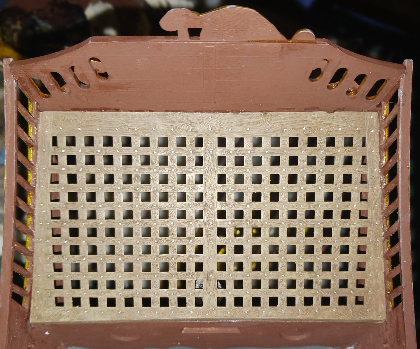
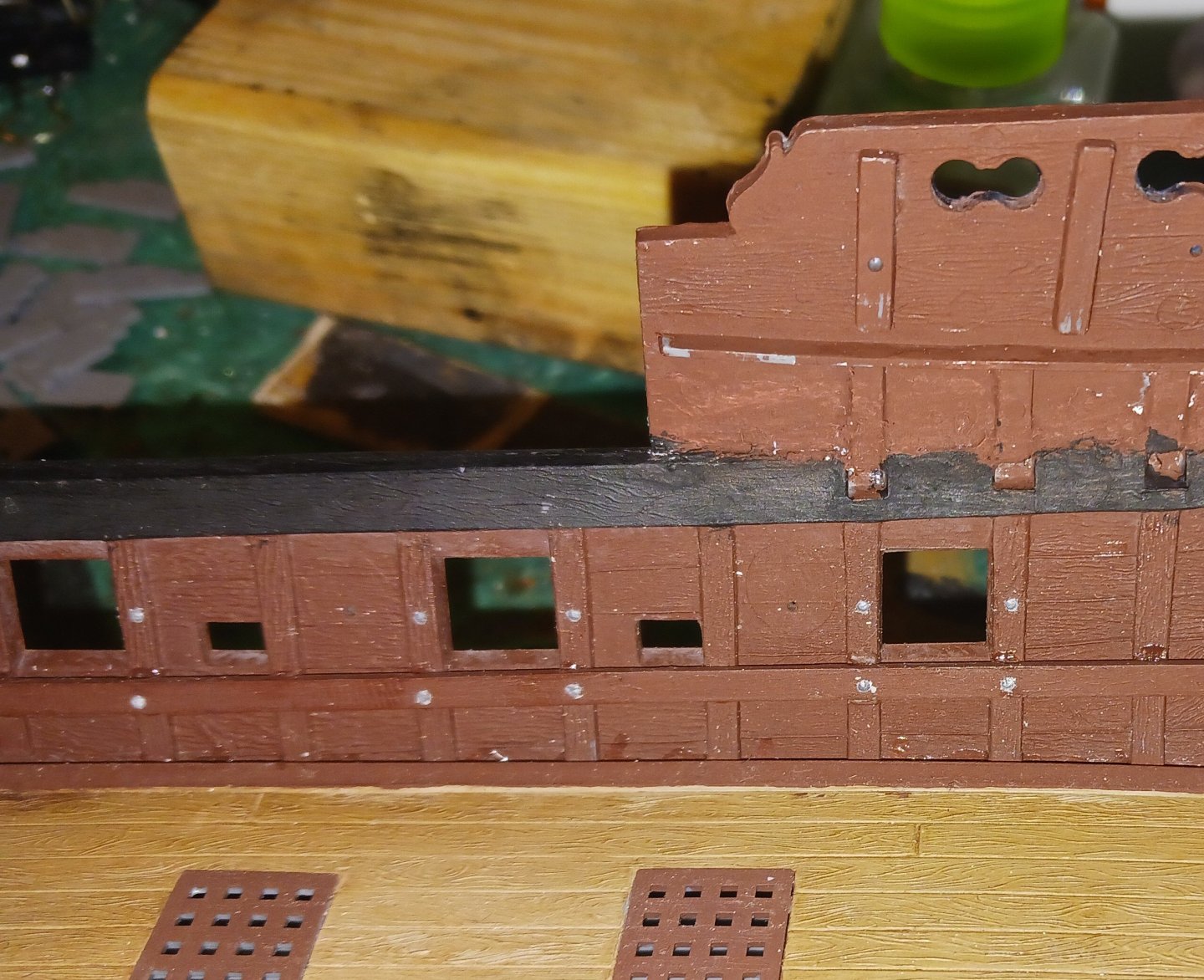
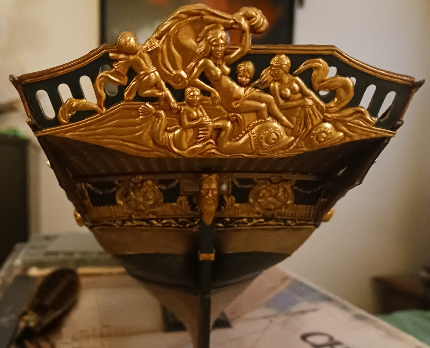
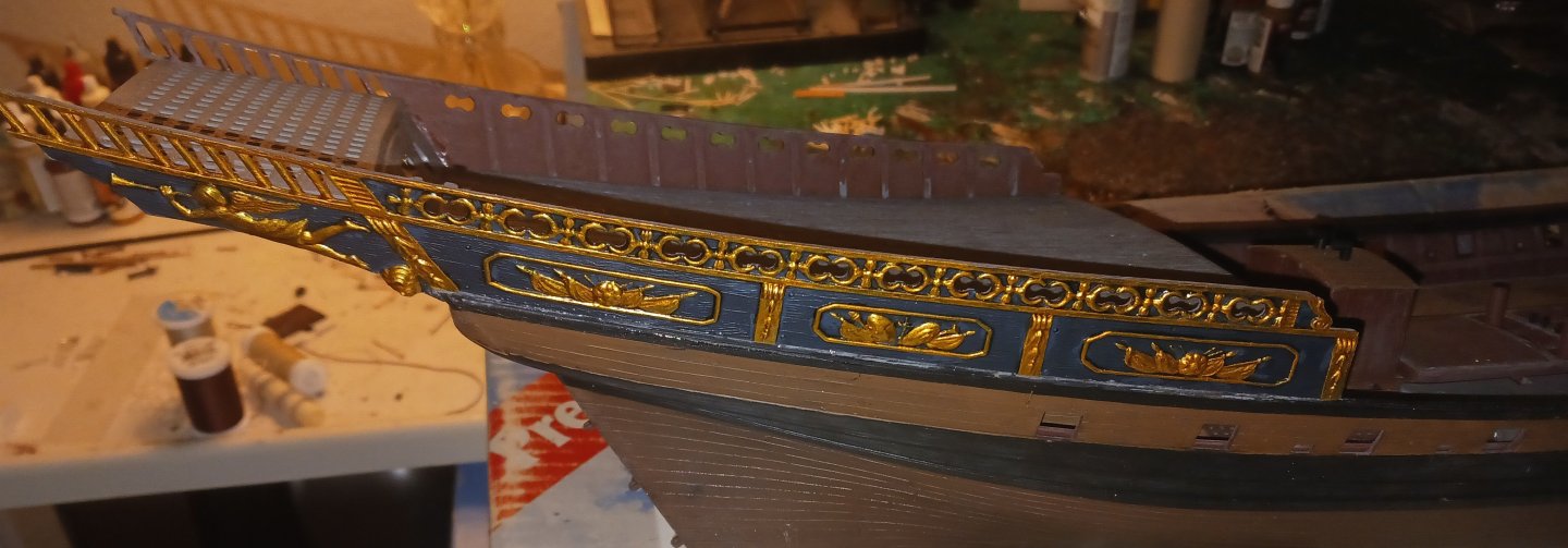
I forgot to post these images. The chebec's paint was able to be mostly restored with brushed water. Furthermore, I have painted some of the rest of the ship, and done work on the stern. I painted and installed the aft grating, as well as the intricate stern filigree piece. Some cleanup has yet to be done on the areas stained with glue. They will be covered with matte varnish. I also replaced the rudder pintles so that the rudder could properly turn.
-
Bryan, what I have personally found is that AI is completely untrustworthy for even the most basic details of ship rigging. AI has no idea what a real ship looks like, and probably never will. I think you would be much better off looking at real examples of these boats built by real people, and photographed by real people. It might be harder to accomplish, but at least you'll get it right.
- 38 replies
-
- 2
-
-
-
- Fischkutter
- Laser Creation World
- (and 1 more)
-
I just popped in on this build log, but I have to disagree and say that this is one of the better plank jobs I've seen on this kit. Keep up the good work! Keep in mind that these were work boats, and they wouldn't have looked nice anyway. People love to model them as yachts, which is how many of the real boats have been restored as.
-
Hello Bear, You should check out Steven @Louie da fly's build of the Winchelsea Nef. It has lots of information you could need for your build. With that said, I find it highly likely that a simple clay oven or perhaps a brick oven like the one found on the Mary Rose would have been used to feed the crew. For the thirteenth century, I would say the former would be more likely. I hope this answers your question.
-
I want y'all to know that the Requin lives. I have done some work on the ship and encountered some major frustrations, prompting me to shelve the ship (literally) for half a year. For the past few days I have considered starting a new Requin (from the Imai kit) but then today, I took the Requin out of storage and found that it wouldn't be that hard to dust off the hull, repaint some parts and genuinely turn the ship into what I originally wanted- a museum model. Hence, I am beginning chapter 2 of this story. Here is the Requin now: It needs a bit of cleanup and repainting, but not much else. The whole thing that led me to abandon this project was a large gap between the topsides and the hull, which I have mostly fixed short of paint, and the fact that parts kept falling off, which can be attributed to me using substandard glue.


-
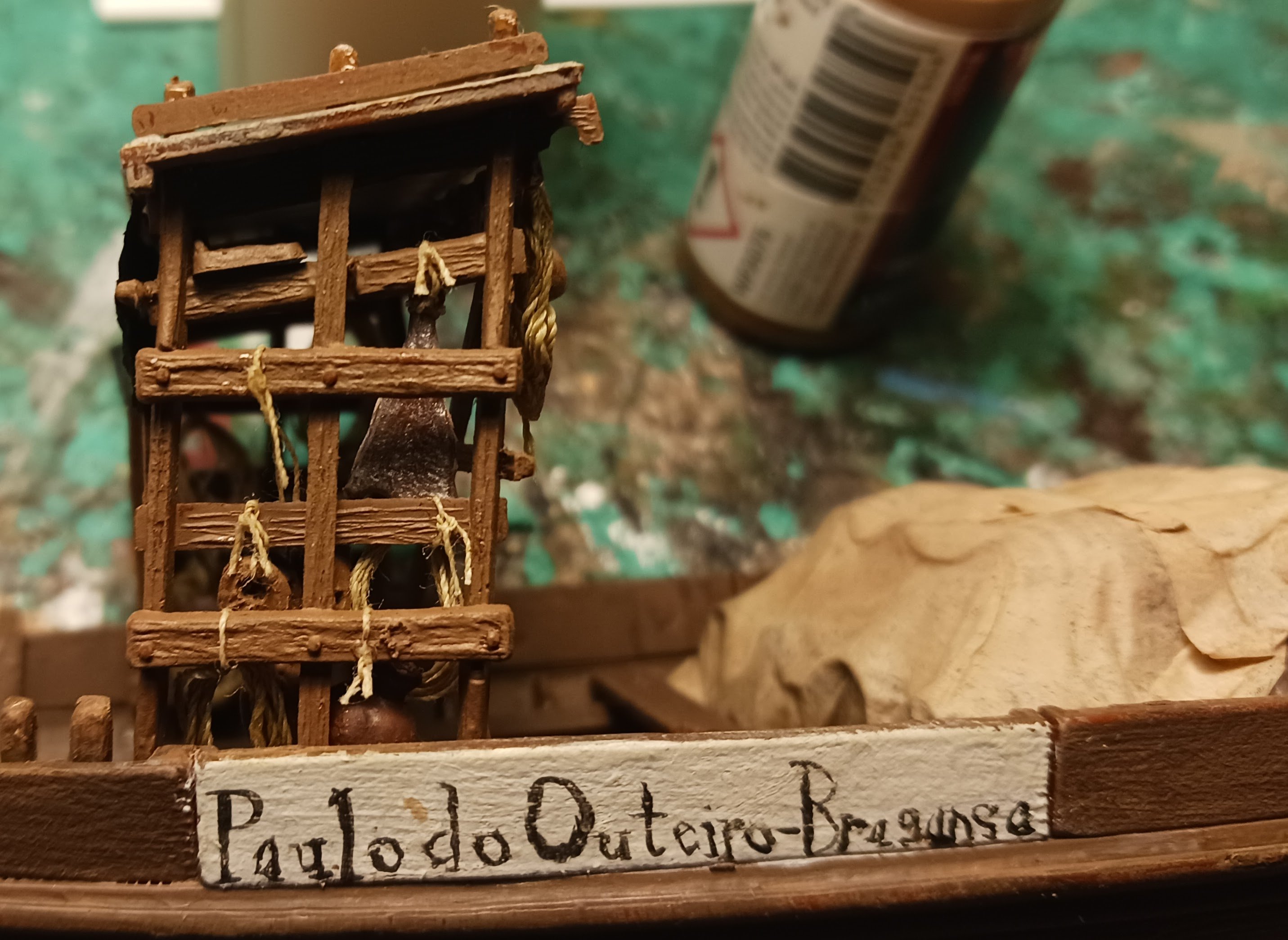
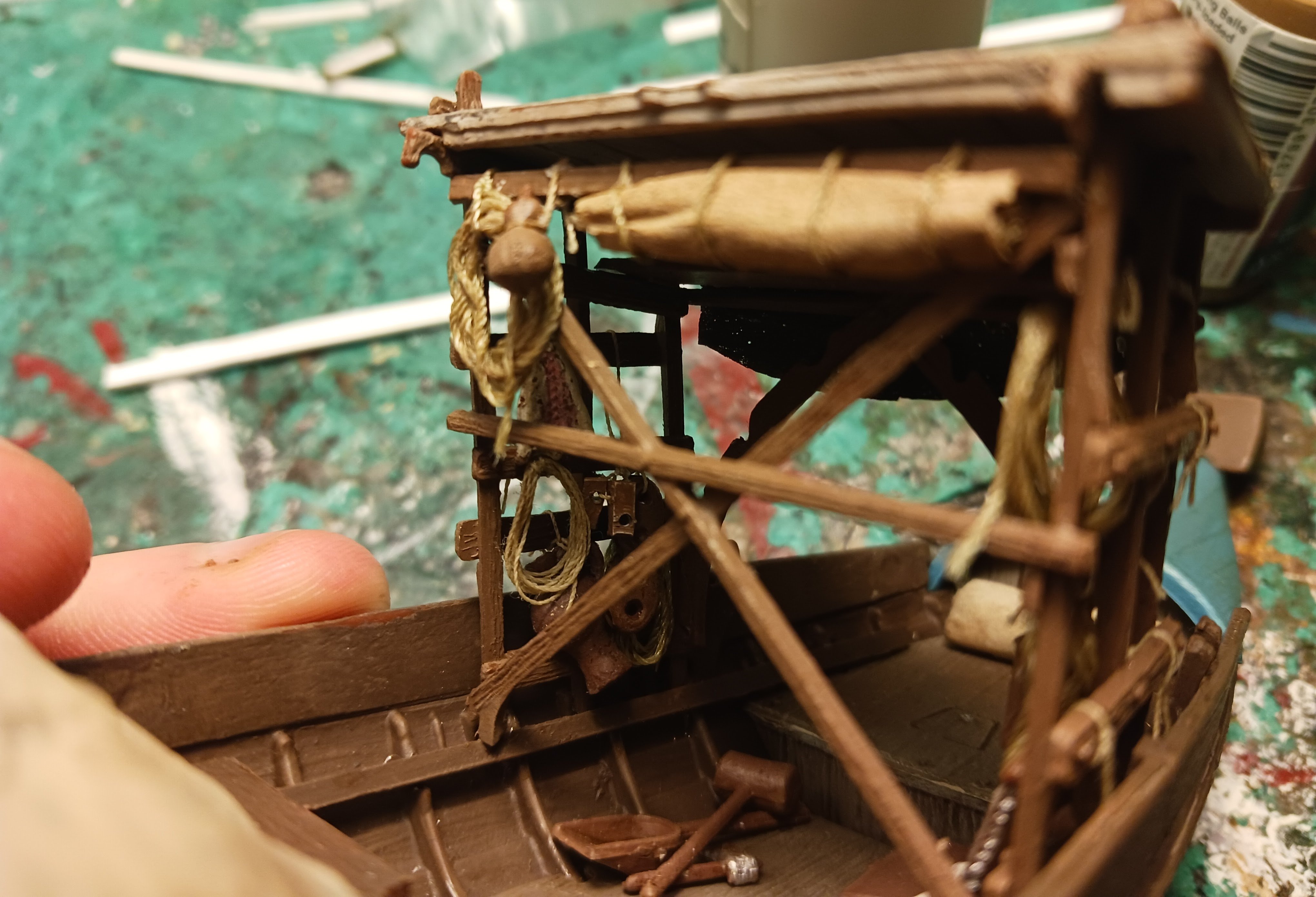
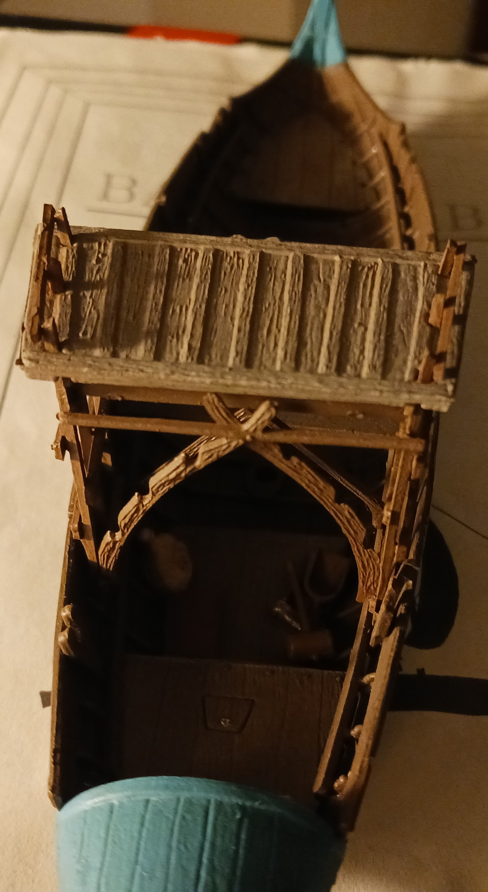
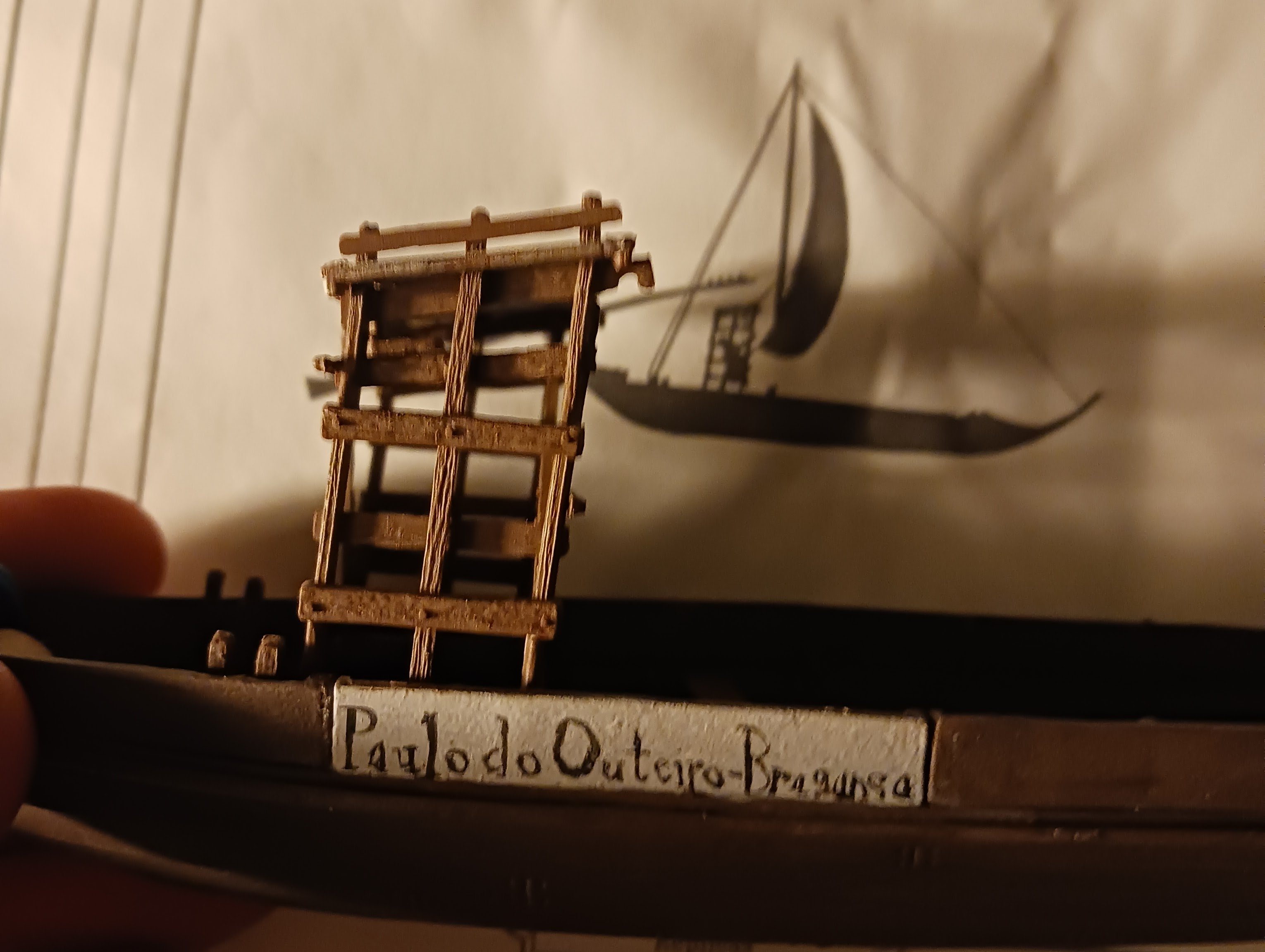
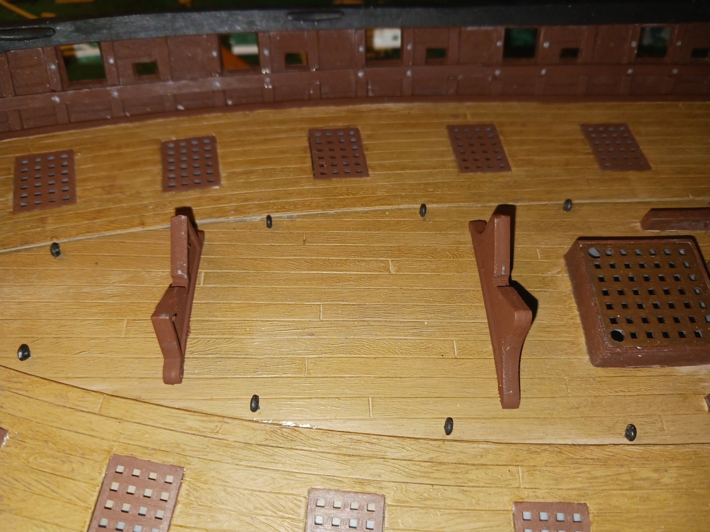
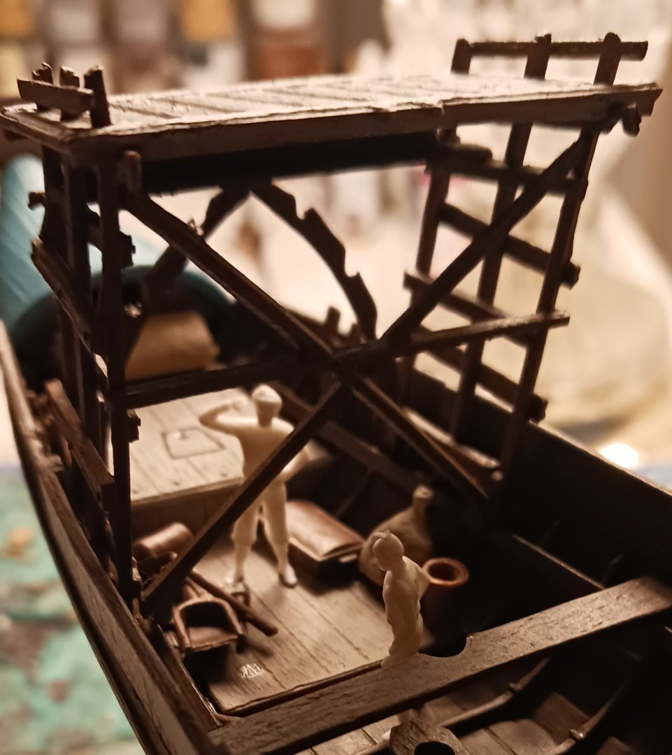
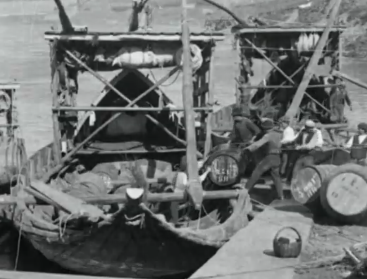
In a long overdue and I assume much awaited update, I have begun work on the apegadas, the large platform that sits above the stern upon which the steersman pilots the boat. I have also made a very interesting observation: The stated scale of 1/75 would make this one of, if not the largest Rabelo boat ever sailed. For that reason, I will be amending the scale to something closer to 1/64. I have stolen some 1/64 scale figures to use as the crew of the boat. This will be my first model to feature a crew, and I already have ideas. Paulo and Miguel argue about the improperly stowed tools and equipment: Some more images of the apegadas: What I have also found is that the crews of the Rabelos had a habit of tying all of their "stuff" to the timbers immediately underneath the apegadas, as shown below: That's easy when the bottom of the platform is at maximum two feet above your head- not ten feet. For that reason, the crew of my Rabelo will have to stow their gear closer to the deck and within reach. That will be the next job.


- 17 replies
-
- 6
-
-
- barco rabelo
- 1/75
- (and 2 more)
-
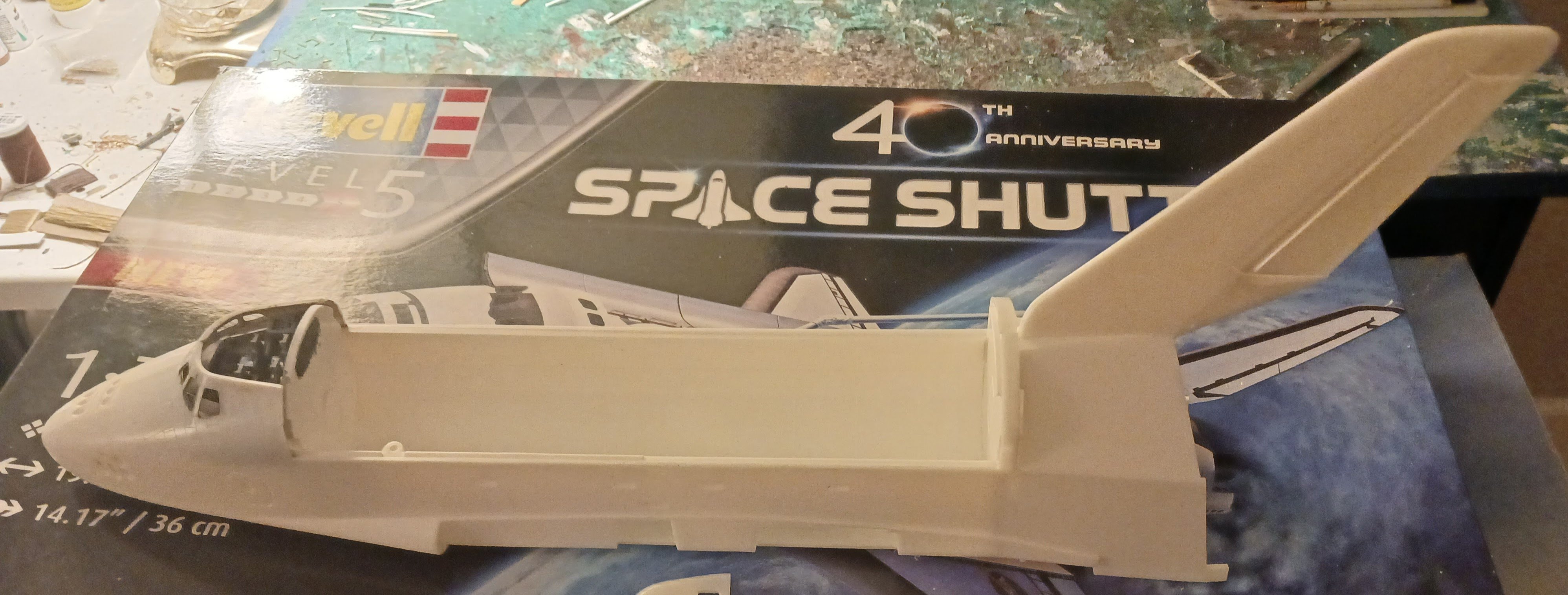
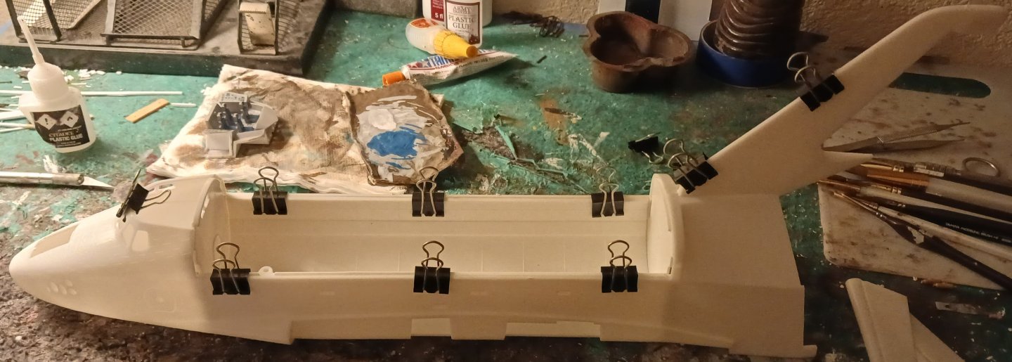
Probably the most difficult and arduous part of the build is now complete. After about a dozen different dry-fits, significant amounts of tweaking and two days, the orbiter halves are glued together. Currently, the roof of the crew cabin is sitting unglued in position. It will be removed for painting. This is what all the reviews said would be the biggest challenge of the entire project, so it should be relatively smooth sailing from here on out. I plan on doing some of the painting of the orbiter before the wings go on.

-
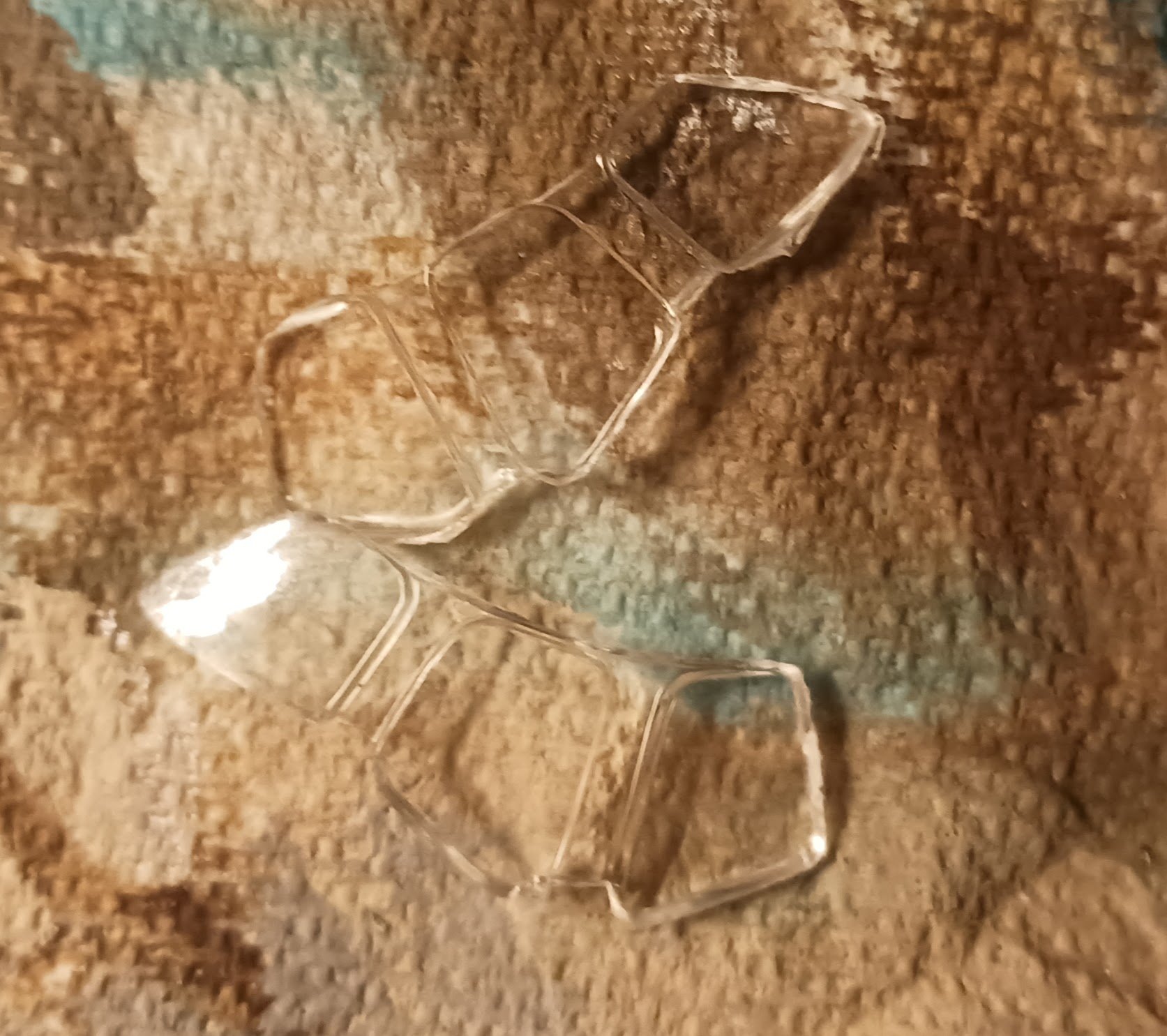
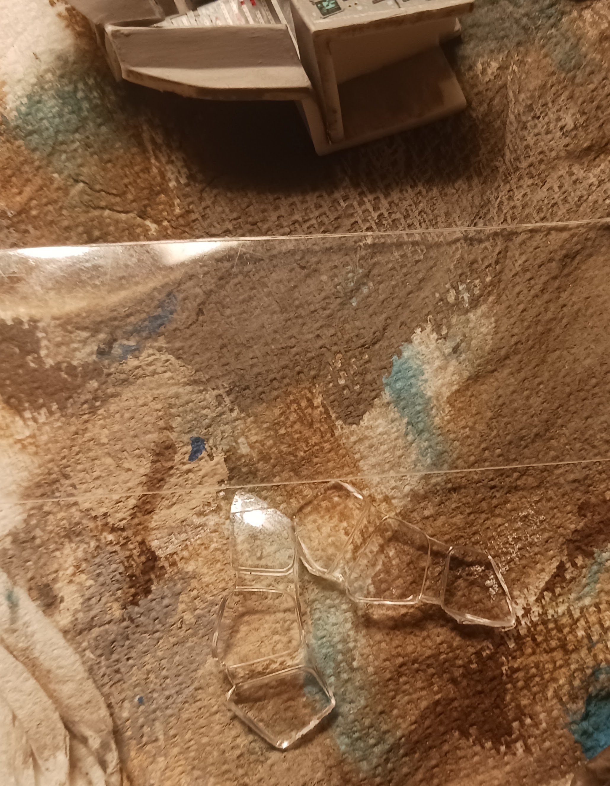
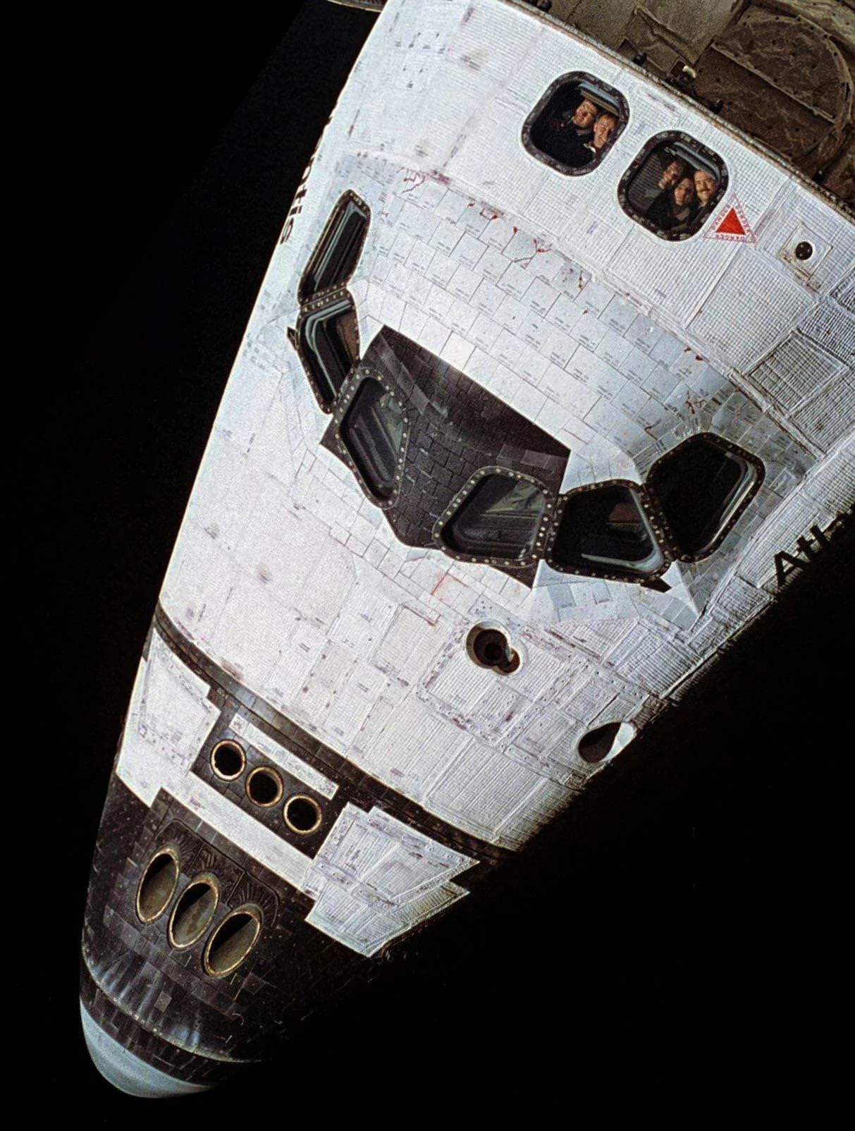
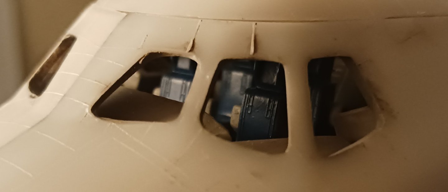
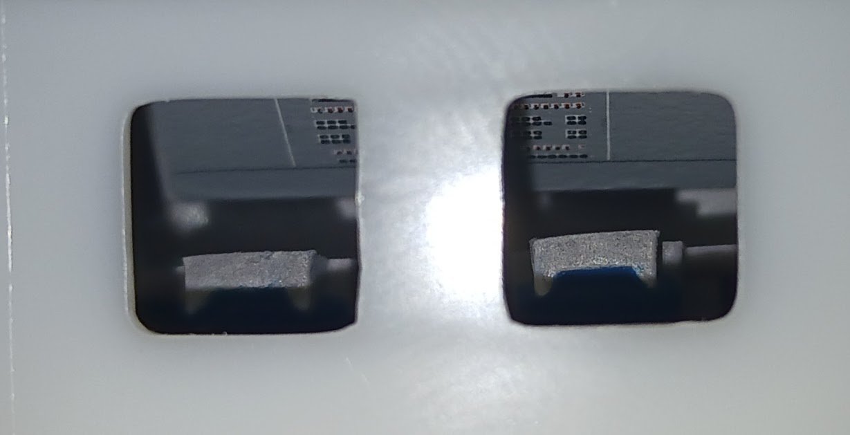
The initial goal was to paint the orbiter prior to assembly, but I think now plans have changed slightly. See, I had initially planned on using Revell's kit-supplied clear parts for the windows of the cockpit. However, upon inspecting the clear parts, I found the kit-supplied clear parts to be the worst quality I have ever seen in my life. Not even the Roden kit I attempted had clear parts this distorted. Honestly, I get that this is an 80's kit, but the fact that they could allow such poor quality to be sold is honestly offensive. Any aircraft with an actual canopy would be rendered unbuildable with this clear plastic quality. I could continue to wire brush Revell, but I decided to make a plan instead. I still have a decent section of clear acetate from a previous model, and I decided that that would be much better than the kit-supplied parts. The plan is to cut apart the Revell parts into the individual windows and trace the outlines on the acetate, leaving a margin around the outside. Then, the acetate windows will be glued to the interior of the window frames. This way, the interior will be at least kind of visible without distracting warpage and distortion of the glass. Real photos show us that the orbiters' windows were not distorted or tinted in any way: More later.


-
Now that I have that out of the way, the next thing on the table is some of the assembly of the Challenger's hull. I will likely do some painting before the assembly, but after that, the flight deck goes in as well as some other things. Here is the orbiter as she appears currently. She will be at least primed prior to assembly, perhaps preshaded as well. I want to do as much of the area surrounding the windows as possible before the windows and flight deck go in. Stay tuned for more!
-
I've now begun to put paint to plastic. First was the orbiter's flight deck, which is admittedly a weak point in the model. This model was originally released with different decals for the earlier orbiters, but when they updated the model for this release, they updated the decals to show later orbiters. Challenger would have had a different flight deck layout. I am not impressed. Luckily, all this will be hidden inside the orbiter, behind the notoriously-low-visibility windows. I think, when Revell updated the kit, they should have included two or three high quality decal sheets with orbiter-specific decals. These decals were thick, chunky and didn't want to go where they were needed. Some of them were even shaped and sized improperly. However, I did what I could with what they gave me. Revell should have also included an extensive photo etch set, which they have done in their modernizations of old ww2-era ship kits. Next will be some of the assembly of the orbiter's fuselage.

-
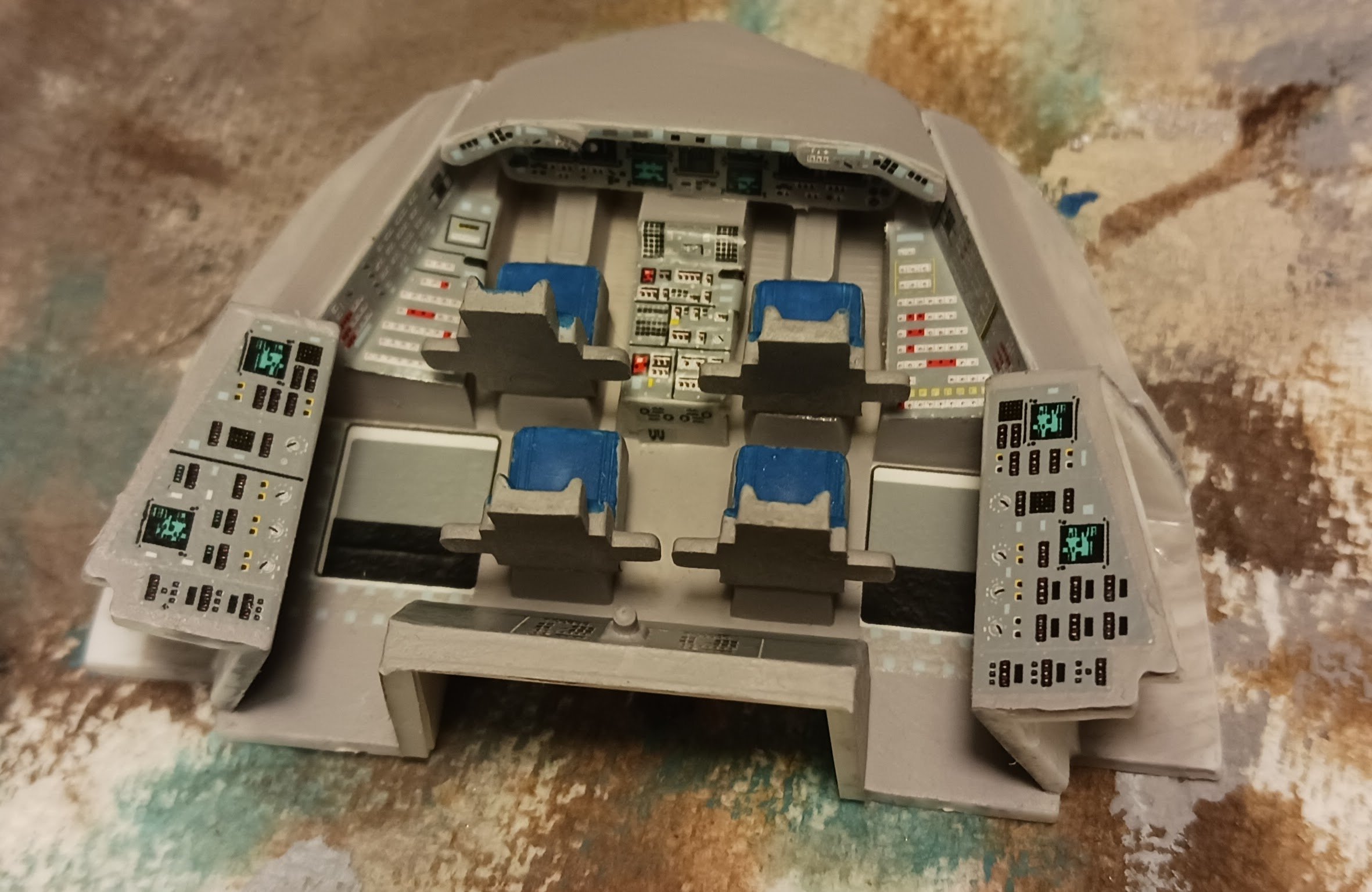
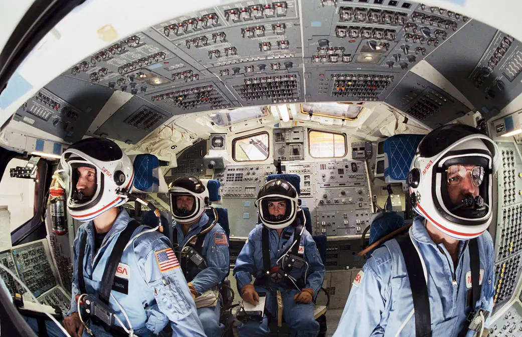
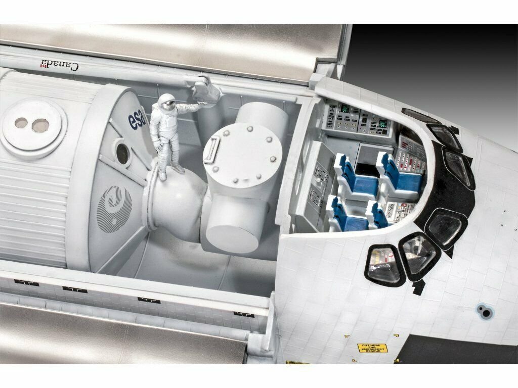
To begin with this build is the flight deck of the shuttle. I likely will not put an extreme amount of time or effort into the flight deck, as it will be nearly invisible underneath the thick, heat-resistant glass of the cockpit and upper windows. Here is an official Revell image of what the flight deck is meant to look like when complete: And here is a picture of the Challenger's actual flight deck: This photo, taken by NASA, shows four members of the actual STS-51L crew training inside the shuttle. Take note of how cluttered the shuttle's flight deck is. Also take note of how flimsy the seats seem to be. This is for multiple reasons- first being the fact that some of the seats were meant to be stowed while in orbit. Secondly, a Space Shuttle seat is not meant to have all of the equipment that, say, a fighter jet's seat would have. The Shuttle was only meant to experience a maximum of 3 G's at any point in the flight, and the astronaut's emergency life support equipment was carried underneath the seat. In fact, when Challenger's flight deck- or what remained of it- was fished out of the Atlantic Ocean, it was discovered that at least two of the astronauts had activated their personal oxygen supplies, and that Michael Smith, Challenger's pilot, had activated several switches on his control panel in an attempt to restore electrical power to the spacecraft. Christa McAuliffe in the commander's seat, 1985:

-
My father was only four years old at the time of the Apollo 1 disaster.