
uscharin
-
Posts
74 -
Joined
-
Last visited
Recent Profile Visitors
1,821 profile views


-
 uscharin reacted to a post in a topic:
Muscongus Bay Lobster Smack by Kenchington - Model Shipways - 1:24
uscharin reacted to a post in a topic:
Muscongus Bay Lobster Smack by Kenchington - Model Shipways - 1:24
-
uscharin reacted to a post in a topic:
La Créole 1827 by archjofo - Scale 1/48 - French corvette
-
hof00 reacted to a post in a topic:
Cutty Sark by uscharin - Sergal - 1:78
-
uscharin reacted to a post in a topic:
Cutty Sark by GarryA - Billing Boats
-
petervisser reacted to a post in a topic:
Cutty Sark by uscharin - Sergal - 1:78
-
uscharin reacted to a post in a topic:
USCG Harriet Lane by Knocklouder - Model Shipways - 1:144 (1/12 inch = 1 foot)
-
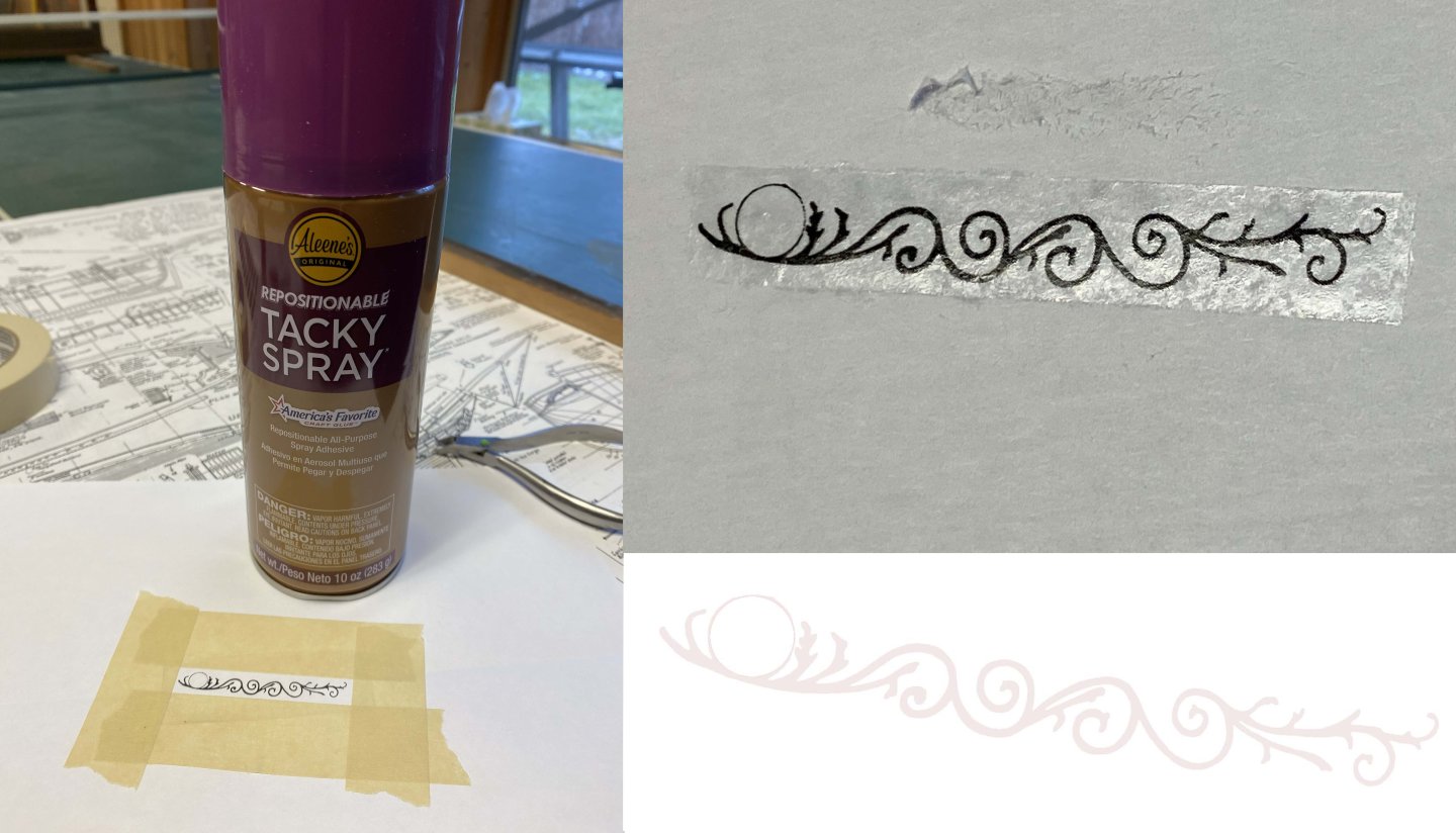
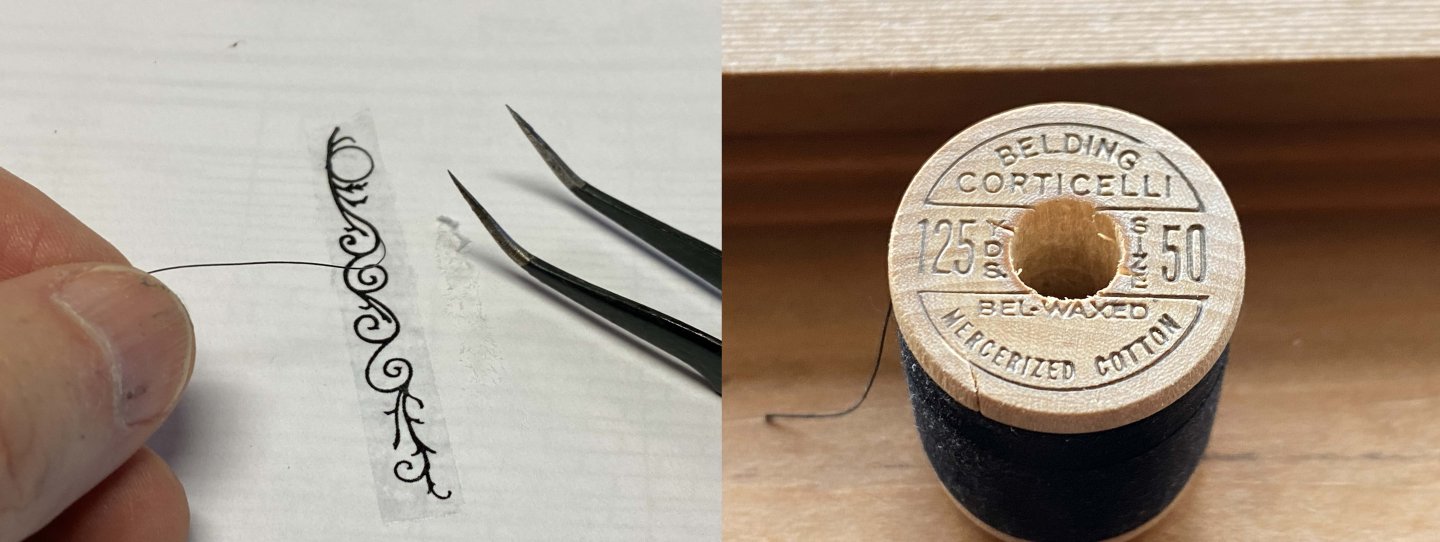
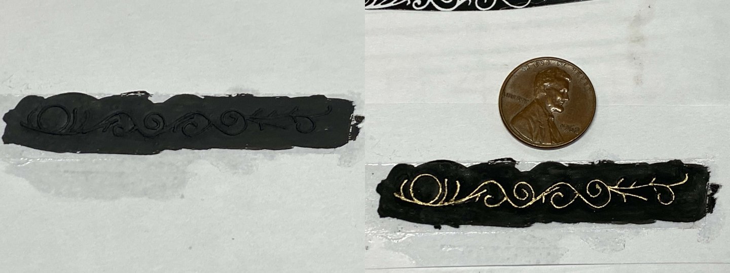
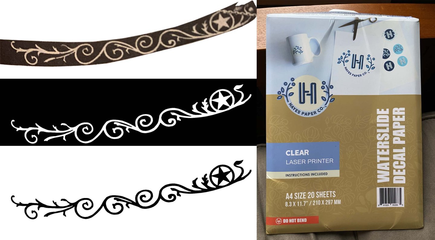
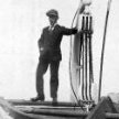 Referring back to post #97 and my paper bow carving; while that attempt was not bad, I almost immediately knew I was not going to ever be happy with it. To me it was too muddy, two-dimensional, and ultimately was not convincing. It looked too much like someone applied graffiti with a spray can. From then to now I dropped everything and set to work to try and find a better solution. This single element has consumed me for quite some time. What I came up with is as follows. It is a solution that has been on my mind for quite some time and always avoided it as it promised to be a very tedious process. In the end, though, the results are better and feel I can finally call it good, or at least good enough. A is current attempt, B is former condition. The process starts out with coating my design with a tack spray. I made a rather heavy application. After drying for an hour or so it is ready for the next step, which is following the design with #50 cotton thread. The thread I used is black and that turned out to be a major problem trying to apply black over black. So redid this process with a much lighter print. If I had this thread in white or red it would not have been a problem. I had a lot of trouble seeing the thread intersections so would tend to either come up short or create an overlap. I altered this process 4 times before I got something that worked. All you had to do was lightly press the thread into the adhesive to keep it from moving around. I started out using raw thread which would tend to flatten out where you pressed it down and it would not rebound. This left a very bumpy surface which would look terrible once painted gold. I ended up dousing the thread with water-thin CA so it would hold its shape followed with a few draws with 0000 steel wool to remove the fuzzy whiskers. The downside of this was the stiffer thread made it significantly more difficult to make a smooth radius. Once I got the thread down, I carefully flowed water-thin CA along the thread paths to lock it down into the adhesive. The CA bonded nicely to the tacky adhesive and would dry hard after a few hours. Next step was painting over the entire area with Tamiya XF-1. This paint likewise bonded nicely to the tacky adhesive and left a hard/firm surface after a couple hours. What turned out to be an annoying problem was painting the thread surfaces with gold paint. Even after burnishing the thread surfaces with the back of my fingernail, the surfaces were still rough enough that the gold paint looked very uneven and broken. Admittedly, I was using a very old bottle of Floquil gold paint. The Floquil label didn't have a barcode which makes it probably 50 years old. It did not flow well even after thinning. I then tried using my new gold Pilot paint pen which did cover the thread evenly but acted like a superfluid and ran absolutely everywhere. I was forced to clean up the mess by trimming with more black paint. At one point I tried thin Cu wire the same diameter as the #50 cotton thread. I had to anneal the wire to take the springiness out of it. The wire was much easier to put down and would have worked great... except when I put on the CA to lock it down the wire would pick up off the surfaces. I never found a way to keep the wire pressed down long enough for the CA cure, so abandoned the wire. I decided to apply the star separately so printed out a sheet of scaled stars and then soaked the paper with water-thin CA. Once hardened, the stars could be cut out cleanly with a razor blade. If you were to use plain paper the edges would be fibrous and easily tear. As a follow-up to post #93 and my quick and dirty etching experimentation, I found the scrap piece of brass I had let sit (unagitated) in 30% ferric chloride for an hour. So here it is. It is clear that the laser toner resist layer worked surprisingly well. I scraped off the resist layer so you can see there was very little undercutting. While this approach was never going to produce the results I wanted, it might find some application down the road.
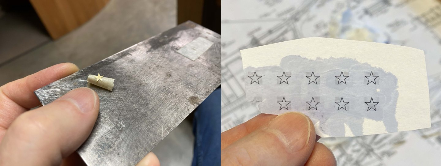


- 101 replies
-
- 2
-
-
- Cutty Sark
- Sergal
- (and 1 more)
-
petervisser reacted to a post in a topic:
Cutty Sark by uscharin - Sergal - 1:78
-
petervisser reacted to a post in a topic:
Cutty Sark by uscharin - Sergal - 1:78
-
 uscharin reacted to a post in a topic:
Cutty Sark by uscharin - Sergal - 1:78
uscharin reacted to a post in a topic:
Cutty Sark by uscharin - Sergal - 1:78
-
uscharin reacted to a post in a topic:
Cutty Sark by uscharin - Sergal - 1:78
-
Yup, I have a strong flashlight at the ready and have used it often. Also, the parts are rarely found where you think they went. Anymore, I try to sweep the floor between sessions to help my odds. I have spent hours on some replacement parts only to find them the next day. The purist in me wanted to draw/paint the scroll work directly onto the ship but it's gotten harder for me to keep my hands still enough. I can print out several copies of my design and if I mess up on one, I just move to the next. I would otherwise need to fix mistakes on the ship before making a new attempt. At my age I'm now cutting myself a little slack.
-
Snug Harbor Johnny reacted to a post in a topic:
Cutty Sark by uscharin - Sergal - 1:78
-
hof00 reacted to a post in a topic:
Cutty Sark by uscharin - Sergal - 1:78
-
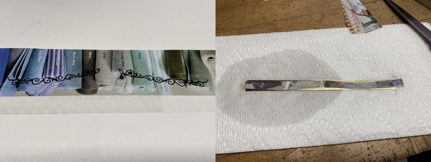
Played around with my decal paper today and the results were disappointing. First thing I did was scale and bend the design in Photoshop until it fit the ship. I would cut out the paper version and apply to make sure it fit properly. First thing I noticed was just how good the paper version looked, to the point I almost didn't bother with the decal paper. The toner almost perfectly matched the hull paint. But, I have the decal paper so wanted to see how it would work. After printing out my design on the laser printer the first thing I noticed was the toner got partially picked up and smeared by the outfeed roller. Toner adhesion is terrible, at least with my printer. You can very easily scratch off the toner by dragging your fingernail across the surface. For sure, you would have to seal this work once you transfer your design. Even though the decal paper didn't look that good I went ahead and tried to apply gold to the scroll work. I initially tried to use my nib pen using some gold paint (I couldn't find any gold ink) and that went badly as the pen tip would quickly foul. It also proved a little difficult to apply paint to the glossy decal surface. The pen would probably have worked great if I had ink. It was at this point I tried to apply the gold paint to the paper version, which was a lot easier but would bleed a little, so the design was not as crisp as I was hoping for. Never-the-less, it didn't look all that bad. I used an old brush that I trimmed to a point and thinned the paint with a little mineral spirit. I ended up using some of the gold paint out of my new Ultra Fine (0.5mm) Pilot paint pen, which turned out to be useless. The tip was too wide and every time you pressed the tip down to feed more paint the line would get wider. I almost went w/o the gold as I'm actually not sure the carving was gilded at this point in time. In fact, I still lean in that direction. Longridge did his work in gold so maybe it was gold. Really hard to tell with B&W photos. I carefully applied water-thin CA around the edges of the paper using a wire loop. I went around it twice letting the CA completely wick up behind the paper. You had to be a little careful as too much CA would melt and flow the paint. I might later go back around with some black paint but honestly without a bright spotlight on it, as in the picture below, you would have no idea there was a paper edge. I also applied silicone to my little lifeboat form. I used alcohol but mineral spirits would likely have been better. It needs to completely cure before I try to apply my planking, which I might try to start tomorrow. Funny how you will see things in pictures that you might not otherwise notice. For example, it jumped out at me in my last post that the hull needed more fairing.


- 101 replies
-
- 3
-
-
-
- Cutty Sark
- Sergal
- (and 1 more)
-
uscharin reacted to a post in a topic:
Cutty Sark by uscharin - Sergal - 1:78
-
uscharin reacted to a post in a topic:
Cutty Sark by uscharin - Sergal - 1:78
-
hof00 reacted to a post in a topic:
Flying Cloud 1851 by hof00 - Mamoli - 1/96 - American clipper
-
I like that table. Maybe it's time for me to go shopping. Your ship is looking great! She has a very "authentic" and natural look. Ron
- 200 replies
-
- 1
-
-
- Flying Cloud
- Mamoli
- (and 1 more)
-
hof00 reacted to a post in a topic:
Cutty Sark by uscharin - Sergal - 1:78
-
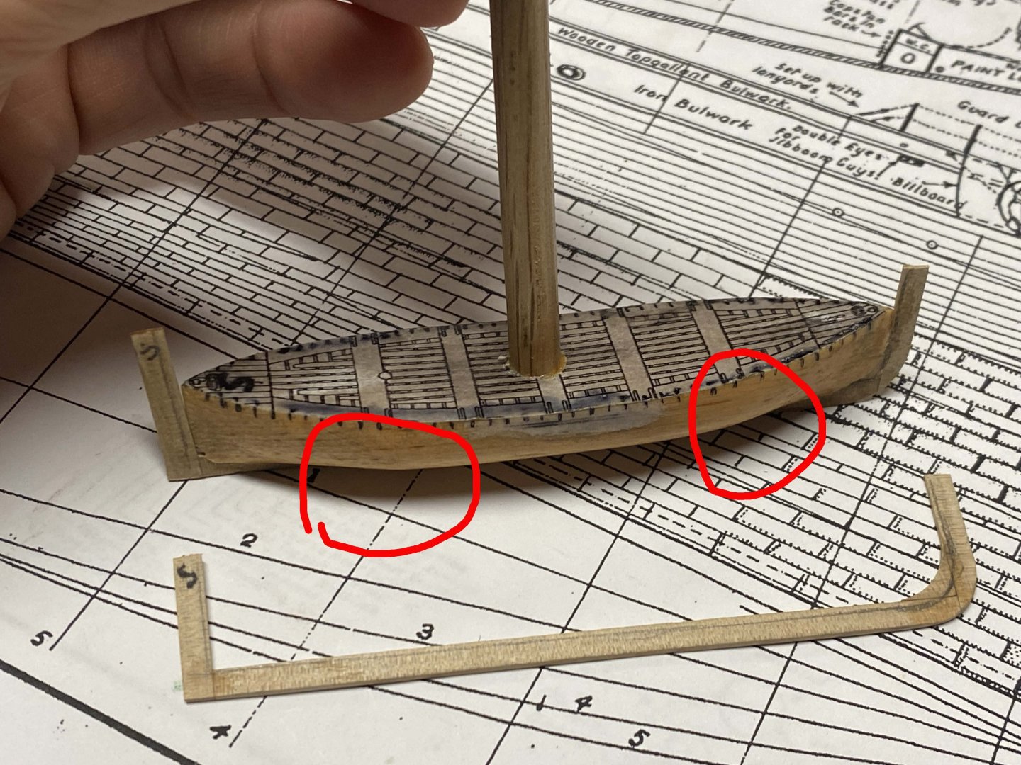
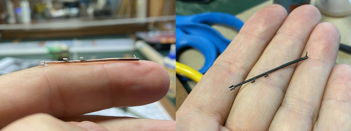
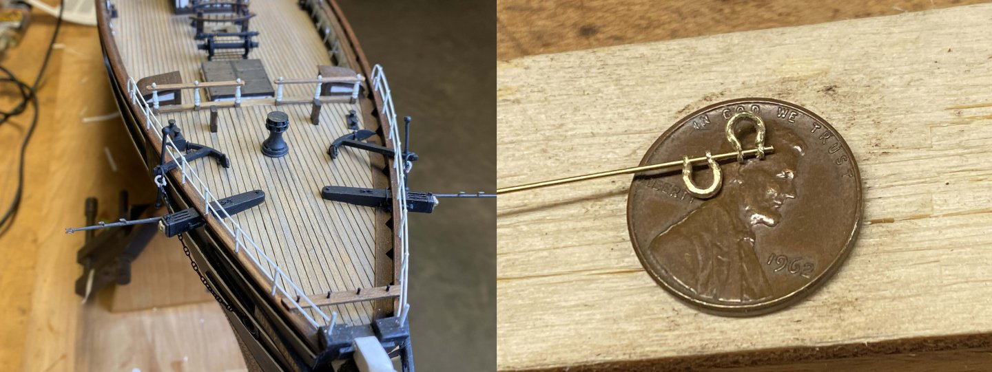
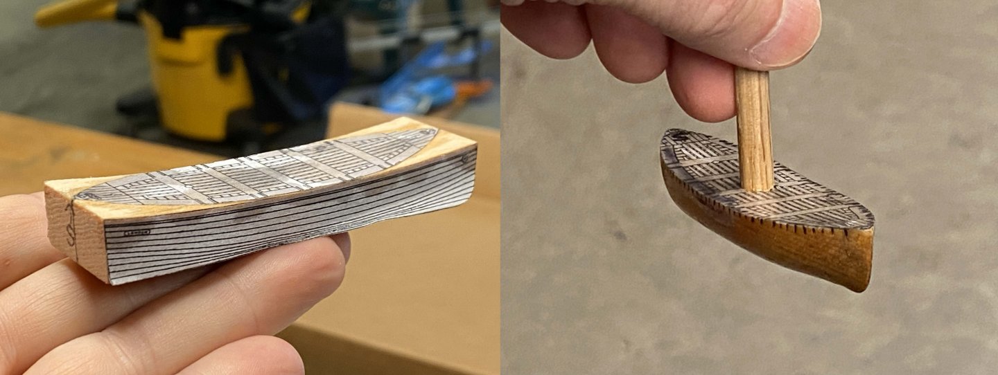
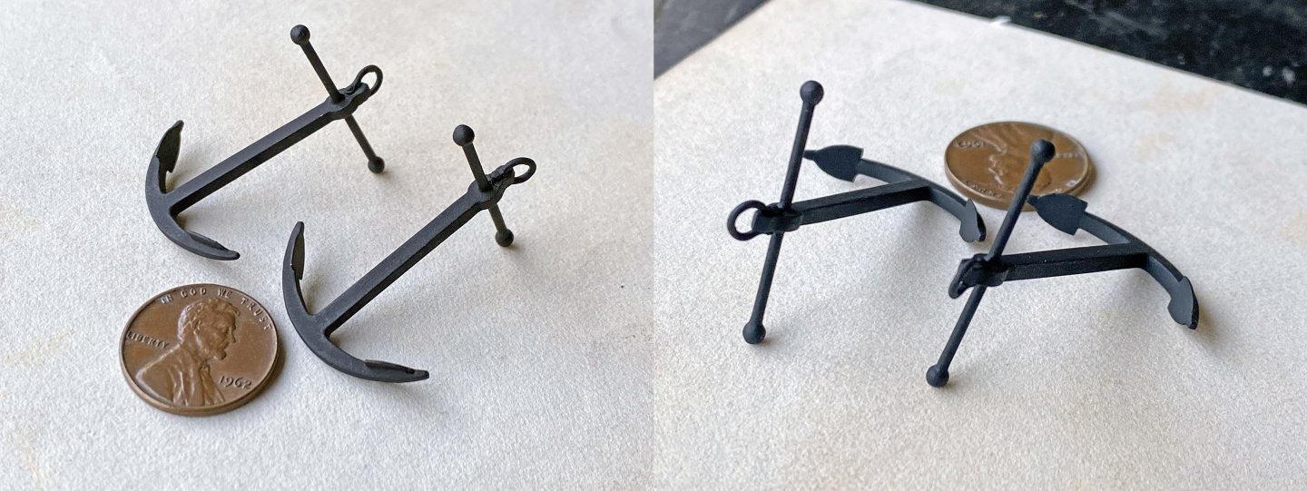
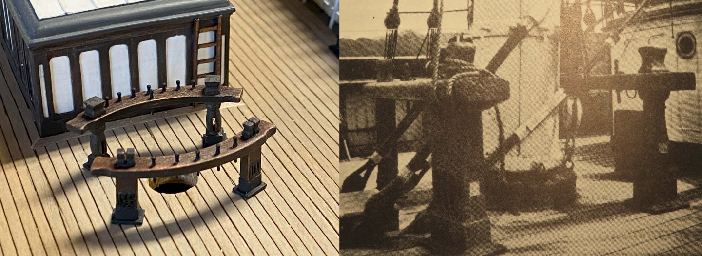
Have been simultaneously working on a number of smallish jobs that are not all completed. Multitasking is not an efficient way to work. The reality is some of my current tasks are not much more than a series of experiments to see what works. Framing the masts: Pretty straight forward but took a surprising amount of time to measure out and remove decking, then color some replacement wood to match decking. The mast diameters are not enough to fill in between frames but when a weather skirt is applied that will cover things up. Unfortunately, my old-work masts will need to be completely rebuilt as there is just too much wrong with them. After the framing was complete, I started gluing down all the items I have been making... chicken prisons, winches, etc. Something always goes wrong at this stage and the big oops this time was one of the chicken coops took a ride down the throat of my shop vac. It could have been worse. Although I made the whiskers and dolphin striker a while back, I had to remove them as they would surely get broken off in the course of modeling. I refitted them on the ship but will take them back off until I get to the rigging. Made out of soft copper wire hammered out to shape. The hammering process turns the Cu hard and not easily bent. Soldering on the clips was an exercise in patience. Mounting the anchors: There are, of course, several ways to display the anchors. While at Falmouth the anchors were stored on deck and the anchor chains used as mooring points, and that never changed. Every picture I have from that period shows the anchors simply laying on the deck with only a protective board under each fluke and not lashed down. As a practical matter, I did lash down the anchors as they would otherwise be constantly moving about. Longridge displayed his model that way, even if it wasn't exactly as it was. In the right-hand picture below, you can see how the almost identical anchor is stored on the deck of the Polly Woodside. I also attached the anchor chains, again, even though that was not how it was in reality. It's simply a matter of practicality. I had to make a couple small shackles out of brass to make the connections. Sections of the railings could be temporarily removed to allow the anchors to be stored on deck. I need to somehow detail that in a way people don't keep asking me how they got the anchors under the railings. Lifeboats and storage skids: This is one of those jobs that is ongoing and outcome uncertain where the lifeboats are concerned. It took some time to figure out the exact locations of skids, as they were moved forward at some point while in the hands of the Portuguese. I have no published plans for this so had to stare at pictures until I felt I got it right. One big difference is that the distance between skids was narrowed, and a section of the aft skid bridge was cut out to accommodate the water tank. The lifeboats are currently a work in progress and am working out the process as I go. I started out making a mold for the shell out of soft pine. I printed out scaled drawings to help and that makes this so much easier. I then made a pair of keels that get notched into the mold. I made the keels very oversized so after the planking is done, I can then shape the keels down to the proper depth. My next step is to coat the mold with silicone so it will be much harder for over-applied CA to grab the mold. To do this I'll dissolve some 100% silicone caulking in isopropyl alcohol, or maybe mineral spirits. CA does not stick well, or at all, to silicone. I've been looking for over various materials to use as planking and in the end, I'll likely use a paper product to achieve the look and scale. That'll be fun. Bow carvings: Concurrent to all these projects is I'm still trying to figure out how to apply the bow carvings in a way that I'll believe. My latest effort was to see if I could reproduce the design in etched brass or copper foil. You can find various methods to apply etch resistant designs from the internet. The easiest and cheapest method I found was to print your design on glossy paper with a laser printer. From there you can transfer the design either by heat (cloths iron) or melt it on with nail polish remover. Straight acetone will work but tended to dry to fast. Once the design is pressed on and the acetone is mostly dry you can peel off the paper. That part seemed to work pretty well except when I tried to sponge off the paper whiskers stuck to the toner, I discovered the toner did not adhere all that well. I later determined that how you clean the metal is VERY important. Initially I simply scoured the surfaces with 0000 steel wool. Turns out that leaves a faint oily residue which guarantees failure. You need to use detergent and water as a final step and then don't touch any part of the surface. I tried using straight acetone as a final rinse but that didn't work well at all. Don't use cellophane tape to hold down your designs. It will melt and leave a gooey mess. As you can see, this process is quite doable. I took this rather thick brass test plate and soaked it in 30% ferric chloride for about an hour and was surprised to see the edges were still quite sharp around the toner resist that was still intact. I sprayed the back of the plate with lacquer to keep it from getting eaten. For some reason I didn't take a picture of that. If I do this again, I'll use thin copper foil and see what happens. As a possible alternative to etching, I just got in the mail some water-slide decal sheets. I have prepared some jpeg files to print out to see how it works. My plan is to print out the design with a black background. From there I will use an ultra fine pen nib (of which I have) and follow the design with gold ink. I can then cut out the design and apply to the ship. We'll see how that goes. I have other ideas on how to use this product but need to see first-hand what can be done. It's a process of discovery. I'm starting to think about rigging so recently ordered a sample pack from Ropes of Scale. They make some really nice stuff. Having the samples in hand is going to make my decisions on which sized to use so much easier.


- 101 replies
-
- 2
-
-
- Cutty Sark
- Sergal
- (and 1 more)
-
petervisser reacted to a post in a topic:
Cutty Sark by uscharin - Sergal - 1:78
-
Hi Kevin, Glad I'm not alone in my fears. Your winch kits sure started to look good to me and when I went back to look them over, they were all gone! I took it as a sign. Ron
-
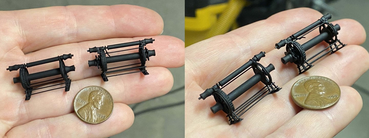
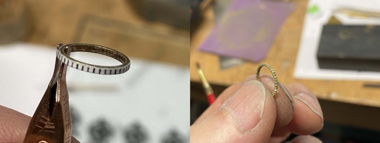
Just today finished the two deck winches and it was a hard slog. Proved to be far, far more of a challenge than the bilge pump. I didn't think that was possible. In the end I'm happy with the overall results; maybe not so happy with the gear rings. The gear rings look OK, and in fact from about a foot away you can't resolve individual teeth. Most of the construction is in brass with some ribs and outboard hubs being in wood. To replicate the outer cast iron supports I sandwiched four pieces of 0.1mm sheet brass and glued them together with CA. I also pinned for good measure and then glued a scaled image of the supports on both outer faces as a guide. From there I pierced the inner captive areas with a drill and hand filed to a rough opening. Using a jewelers saw I trimmed the outer areas then rough filed. To start forming the ribbing I cut narrow pieces of tubing for both faces of each support. The tubing I had on hand was a little too small so split the rings and wedged open to hit the correct diameter before soldering. Once the rings were in place I then filed them down to the appropriate depth. The brass feet were next, which are soldered in place. Wood was used to make the remaining ribs for the same reason I used wood on the bilge pump supports in post #80. The gear rings were next and proved very difficult. I tried a number of approaches, and nothing worked as well as simply free hand cutting them using a paper template. I definitely got better at it with practice, but still far from perfection. To make the rings I cut slices of the same tubing I used for the support ribs and then soldered an additional layer of brass to get a thicker wall. I counted 84 teeth on the original CS winch main gear ring, which was going to be impossible for me to pull off. I ended up making a template for 40 teeth, which my printer was happy with and in practice could accommodate my smallest razor saw. The second of the two rings turned out way better than the first and I'm sure if I had the patience to make more the results would have been progressively better. My biggest problem was the paper template would keep tearing up and off with each fresh saw cut and made precision almost impossible. If I ever do this again, I'll epoxy the paper on instead of using CA. Of course, the alternative would be to invest a few thousand $ in clock gear cutting equipment and accessories and spend a few months learning how to use it... or resin print. The top and bottom inner drums are made with brass (original is wood), while the outer drums are wood which I turned on my hand held Dremel tool. The two deck winches differ a little. The forward winch has a pair of wildcats (pocket drives) on the main outer hubs for pulling up the anchor chain slack before dropping into the chain lockers. Of course, the wildcats were useless after the Portuguese installed a new windlass. Like with the end supports, I sandwiched small pieces of brass plate together rather than cut each individually. The two pictures below illustrate some rough filing. Hard to tell, but I'm starting to round off the ears in the second picture. I have yet to glue down any of the bollards, fife rails, bilge pump, or winches. I think in the coming days I'll need to stop making things and start installing. Truth is, I find installing this stuff pretty stressful. There is always the risk of getting positions wrong, smearing glue, etc. Before I started work on the winches, I made the anchors. They turned out pretty nice. At some point in CS's history, and I don't know when or how, the starboard anchor was fitted with a wooden stock. My personal theory is one of the original iron stock arms broke off or at least became seriously weakened. The wooden stock would have been a good solution. I find the wooden stock to be quite awkward and looks out of place, even though that is how it existed at Falmouth. I finally decided to restore the anchor to its original condition, and I'll sleep just fine. Nothing complicated here, just cut out the shanks and arms then solder together. You can't tell from the second picture, but I filed a pocket for each fluke so the palms are flush with the arms. I hand-formed the terminal balls from brass rod using my Dremel. Drilling the holes was a little bit of a pain and a couple escaped in the process. Tinning the entire ball surface with solder almost completely filled in all surface imperfections.


- 101 replies
-
- 1
-
-
- Cutty Sark
- Sergal
- (and 1 more)
-
ClipperFan reacted to a post in a topic:
Staghound 1850 by rwiederrich - 1/96 - Extreme Clipper
-
Rob, This page served as a bookmark in an old book I was thumbing through this morning. Immediately thought of you. Article is not complete but Is from a ca1932 Popular Mechanics. And Stag*Hound is spelled... Staghound. Haha. Love how your mast is looking, Ron

-
After the bilge pump I needed to do something relatively easy. I'm happy to say the hen coops turned out well and are ready to be installed. The coops were widened at some point before arriving at Falmouth. The current CS restoration/reproduction has them close to their original as-built size. You can see in this early Falmouth image that there is an extra foot. This extra foot marks the original outside corner and was no doubt still in place in order to support a weak rail splice. I made up bar panels and glued to rectangular wood tops and bottoms. Hard to believe the coops consumed over two feet of 0.45mm brass rod. I had to tack-glue the coops to a stick in order to spray paint them. The original coop bars were made out wood and were square(ish). One of my sons was recently in London on business and took time out to visit the CS. He reports it was a great experience to see it in person, something I have yet to do. The "water" dome that the ship sits in always leaves me unsettled. The effect looking up at the ship from within is quite grand. On the exterior, it looks like she is sitting on a water balloon that is about to burst. It is absolutely not complimentary to the lines of the ship and find that very unfortunate.

- 101 replies
-
- 2
-

-
- Cutty Sark
- Sergal
- (and 1 more)
-
Haha, yes, I'll enjoy making them, but it will also likely be a little painful. The iron end castings are where the real work will be. Thanks for the compliment. Just finished looking over your 3d printed CS offerings. Really nice prints and the resolution looks really good. Must be a pretty nice printer. If you offered your parts in my scale I might have been tempted. Kevin, your CS model looks great but I'm sure your Victory is soaking up all you time and effort. Ron
-
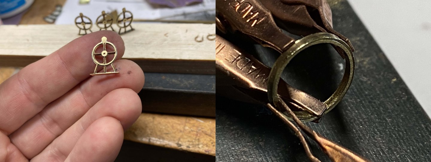
Can't believe this little bilge pump took me three weeks to build, but it did. Turned out to be pretty challenging. Most of the parts took me at least two attempts to make and I had to walk away several times to gather myself. In the end, I have something I can live with. I think my next task will be the chicken coops before tackling the deck winches. As with the fife rails, the pump is not glued down yet. I'm waiting until the masts can be set in place to help with positioning. Most of the pump is made out of brass. The wheels were perhaps the greatest challenge. What you see below is how I managed it. I first formed a ring out of brass wire and then drilled holes to receive the spokes. I then made the hubs by drilling receivers for the brass spokes in solid brass rod. I kept both hubs together, as you see in the middle pictures, until I could lace the spokes and solder. After the first wheel was finished I parted it from the rod and moved to the second. In my first attempt at this I cut the hubs out first which was disaster as it was pretty much impossible for me to manipulate the hub while lacing the spokes. Leaving the hubs attached to a rod make it much easier as I had something to hang onto during the assembly. The pump cans came next. I filed a face on a brass tube (see first picture) and then cut sections that then got soldered together in pairs. That worked out great. The iron support posts were pretty tricky but was able to make mostly out of brass (middle picture). The problem came when trying to solder the opposing ribs. The part would heat up too fast causing the entire assembly to fall apart. The solution was to glue in wood and then shape (third frame).


- 101 replies
-
- 5
-
-
-
- Cutty Sark
- Sergal
- (and 1 more)
-
Congratulations! Glad you have it under glass and really like how you did the sails. You can be proud. Ron
-
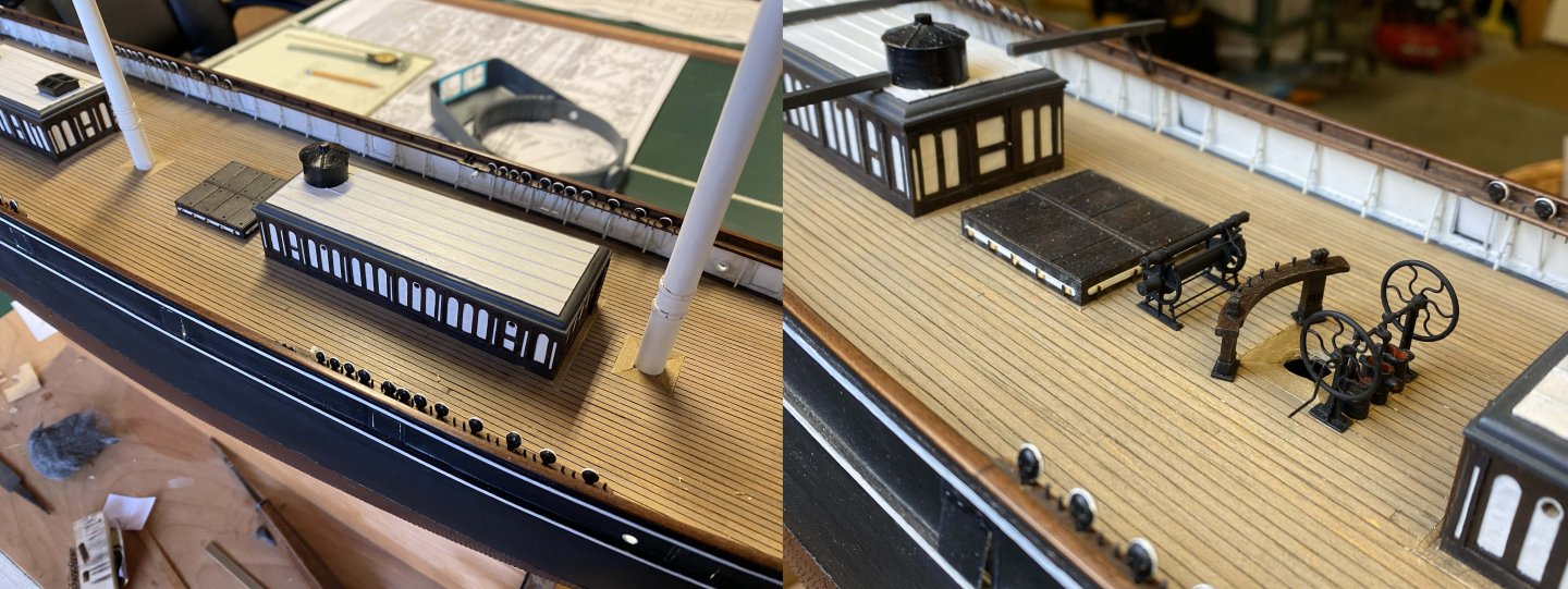
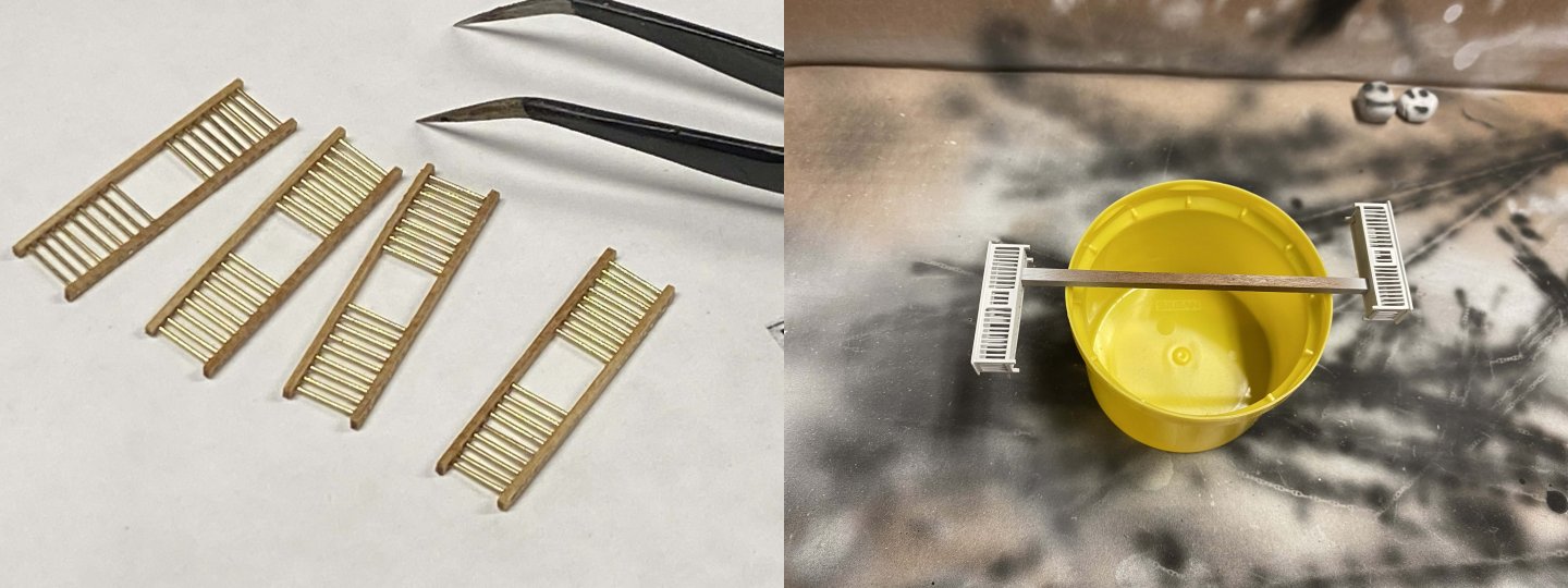
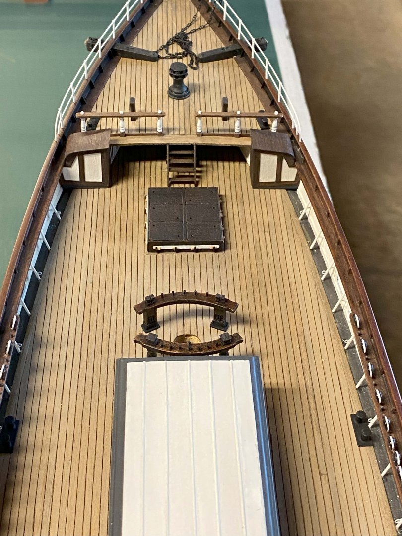
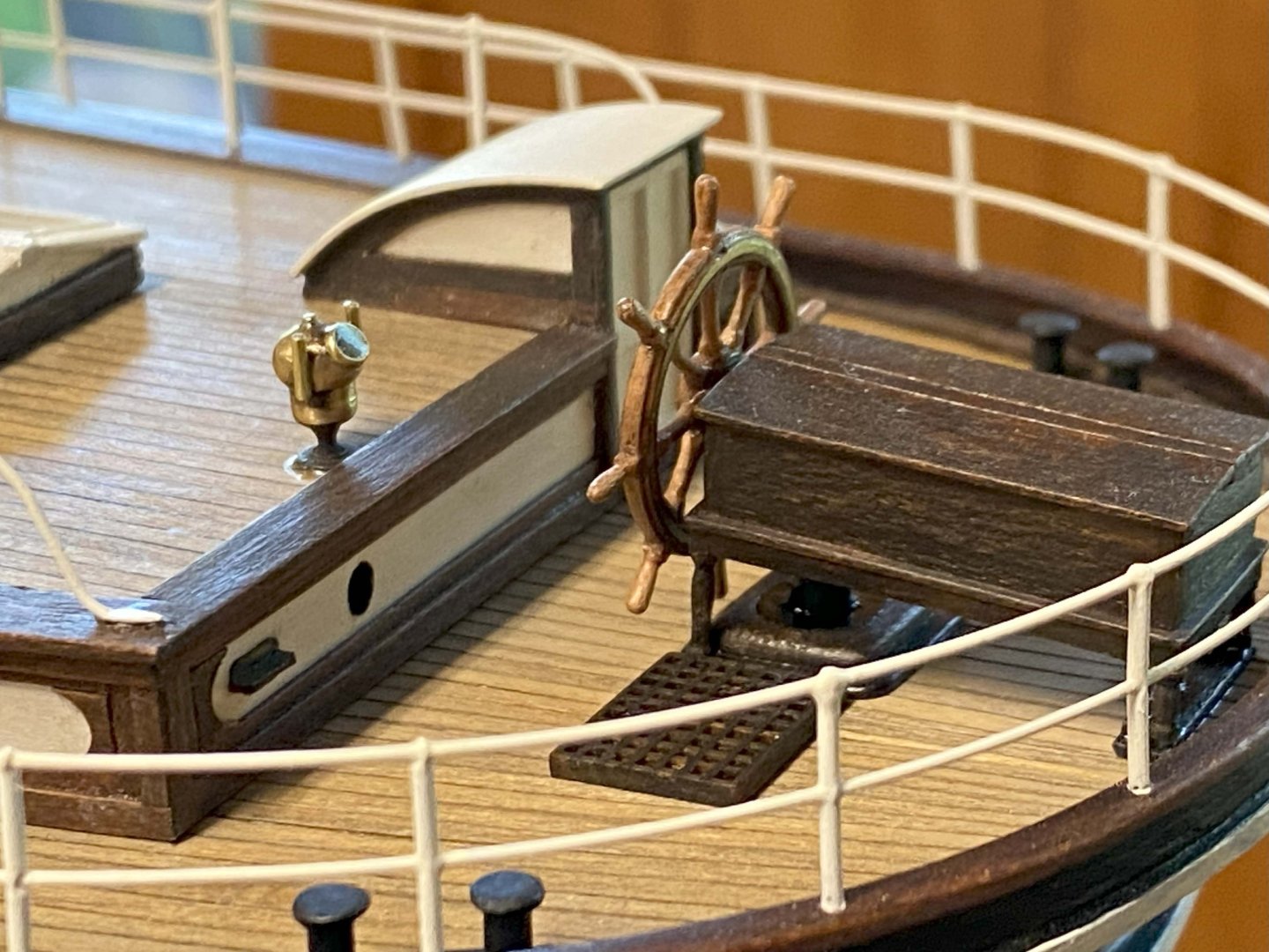
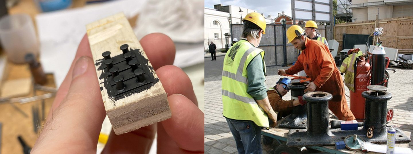
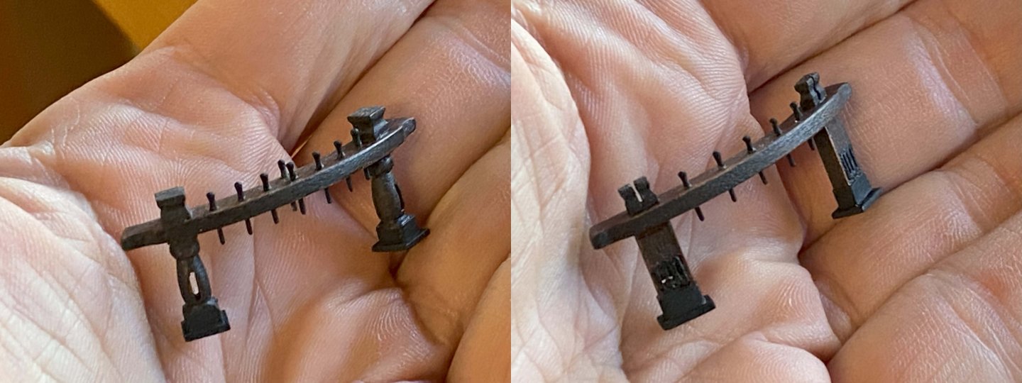
Most of this update is work done about a month ago, at which point I had to stop ship building and tend to a couple domestic projects before the weather shuts me down. I had to chainsaw up and split two very large trees that blew down this last spring. I then restructured an external wall in my house so I could install two new windows. Everything seems to happen in threes, so it was no surprise when my geothermal heat pump broke down needing some significant attention. All of that is behind me now and today I am just resting my bones and thinking about ships. Bollards. Made all of them out of brass, which is very suited to the task. As usual, I didn't appreciate how much work they were going to be. There is a dozen of them in total, some very small that mount to the main deck rail and the biggest ones that mount on the main deck. The largest ones on the main deck, in reality, also can serve as vents. I added a picture of some men restoring the brass screw vents. I had intended to add unpainted brass caps to my bollards but decided not to when I realized they were painted over with black paint at early Falmouth. A lot of brass was painted over at that point in time to save on maintenance. Fife Rails. It is often said that it is important to research the period in time that you intend to model. Over a ships history so much can change and that is especially true of CS. The fife rails are a good example of this. The as-built arrangement of main deck fife rails is different than what you would see in today's restoration and again different than what you would have seen at early Falmouth. At Falmouth the foremast was flanked by two rails, one square-posted (fore), the other round-posted (aft). The main mast had one (fore) square posted rail, where the as-built arrangement would have had an additional aft mounted square-posted rail, which apparently ended up going to the foremast when the Portuguese owned the ship. In today's restoration the round-posted fife from the foremast is now aft of the main mast and bilge pump. The early Falmouth arrangement was no doubt executed by the Portuguese, and probably when it was re-rigged as a barkentine. Wish I had more pictures to share of my work. I seem only to have pictures of how I made the square-posted sheave escutcheons. The square-posted version has three sheaves on each post where the round ones have a single sheave, which I have yet to complete. I have not glued down the rails yet as I'm still not sure of the spacing from the masts. I included a ca1922 picture provide by Longridge of the foremast arrangement at Falmouth. It looks to me that the aft rail sits closer to the mast, but not sure. Originally, the round-posted rail was located where the square-posted fife sits. It was brought to my attention that the binnacle would have been kept polished and I had to agree, even though I'm sure its maintenance would not have been up to seaworthy standards. I tried my best to polish it without breaking it off and then lacquered it. At some point I'm going to shave down the wheel grips a bit as they are simply too big for my liking. Here are a couple overviews of the ship. Getting there... slowly.


- 101 replies
-
- 2
-
-
- Cutty Sark
- Sergal
- (and 1 more)
-
Hello Julie, Am enjoying your work as you come at this sort of project with a unique background and diverse skill sets. I find it very interesting and refreshing. Had never considered using hide glue on my model. Personally, I use a variety of adhesives but mostly 5-minute epoxy and some CA. I have used hide glue for decades on various restoration projects, primarily veneering. For sure it has many advantages, but convenience is not one of them. I'm curious how the hide glue works for you in ship modeling. Keep up the fine work! Ron
-
Some nice symmetrical wire bending on the step railings. That isn't so easy to do as I recently found out. Looking great.