EricWiberg
-
Posts
236 -
Joined
-
Last visited
2 Followers


-
 EricWiberg reacted to a post in a topic:
Soleil Royal 1671 by EricWiberg - Heller - 1/100 - PLASTIC
EricWiberg reacted to a post in a topic:
Soleil Royal 1671 by EricWiberg - Heller - 1/100 - PLASTIC
-
 Hubac's Historian reacted to a post in a topic:
Soleil Royal 1671 by EricWiberg - Heller - 1/100 - PLASTIC
Hubac's Historian reacted to a post in a topic:
Soleil Royal 1671 by EricWiberg - Heller - 1/100 - PLASTIC
-
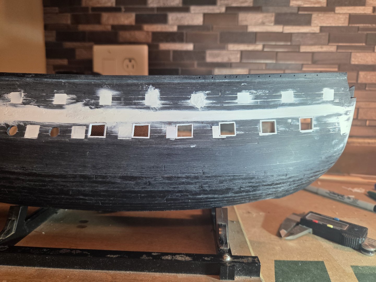
Fifteen Middle Gun Deck ports are now pierced on the starboard side. The Middle Deck gun ports for the 18# cannon are 8.3mm X 7.7mm (36" x 30" at scale)... the Lower Gun Deck ports are 10.0mm X 9.3mm (39" x 33" at scale). Now on to finish the port side piercings, and thus a very realistic chance at starting the wales later this week!


.thumb.jpg.afeee3cea5d074d364d59f44e9bc19ab.jpg)
- 452 replies
-
- 1
-
-
- soleil royal
- Heller
- (and 1 more)
-
ccoyle reacted to a post in a topic:
Soleil Royal 1671 by EricWiberg - Heller - 1/100 - PLASTIC
-
Hubac's Historian reacted to a post in a topic:
Soleil Royal 1671 by EricWiberg - Heller - 1/100 - PLASTIC
-
ccoyle thank you.. I thought that this was the first time I changed it, and I did that because the title said that I started this 45 years ago, which is not quite true now. Again..no more title changes!
- 452 replies
-
- 1
-
-
- soleil royal
- Heller
- (and 1 more)
-
Marc, I have to say..it was a lot easier than I thought. I am really looking forward to the Middle Gun Deck.. and then the Wales go on
- 452 replies
-
- 1
-
-
- soleil royal
- Heller
- (and 1 more)
-
EricWiberg reacted to a post in a topic:
Soleil Royal 1671 by EricWiberg - Heller - 1/100 - PLASTIC
-
Hubac's Historian reacted to a post in a topic:
Soleil Royal 1671 by EricWiberg - Heller - 1/100 - PLASTIC
-
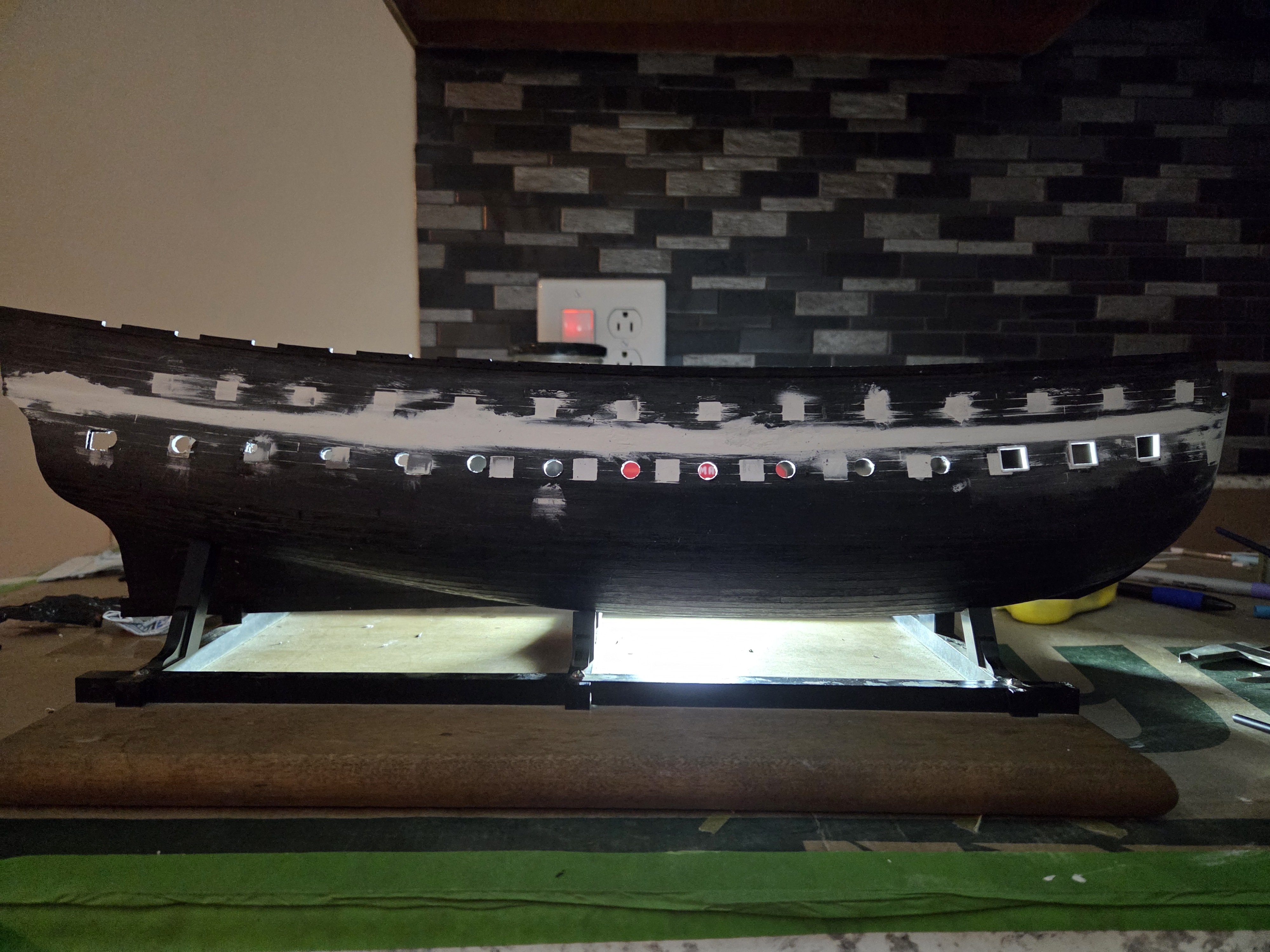
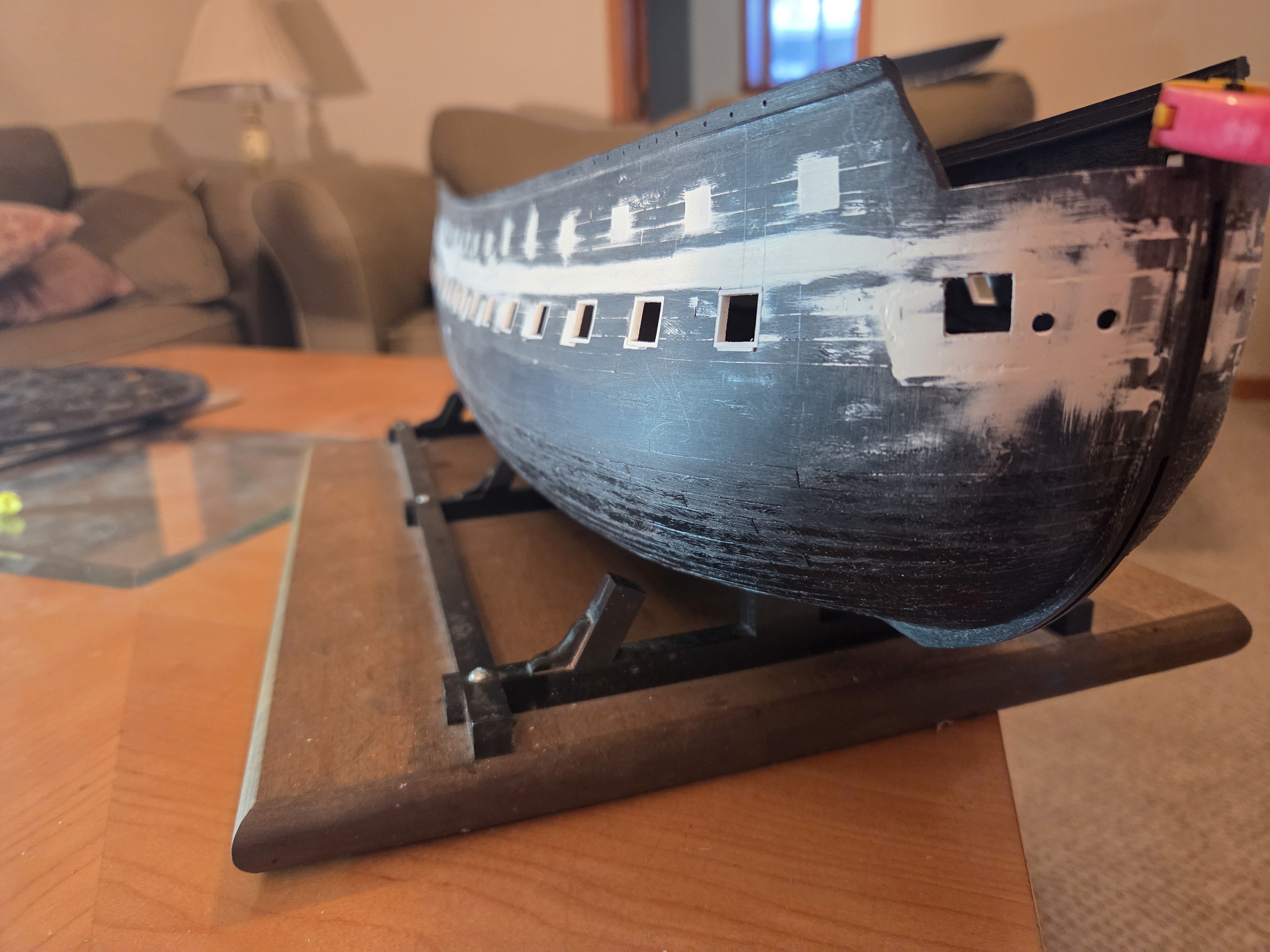
Phew... both port and starboard sides are now pierced for 16 gun ports on the Lower Gun Deck. I will make triple-check my calculations and lay some templates on the Middle Gun Deck to make sure that I have the desired quincunx pattern before I start piercing the 15 gun ports on the Middle Gun Deck. The last of the 5 photos tries to capture a waterline picture...
.thumb.jpg.c4074006bf517ad86c9cf540f4c000a1.jpg)

.thumb.jpg.1928aac0459ca3e67d64bac7efba15d9.jpg)

.thumb.jpg.b788496cc280526b9241b7498aaadc59.jpg)
- 452 replies
-
- 1
-
-
- soleil royal
- Heller
- (and 1 more)
-
ccoyle reacted to a post in a topic:
Soleil Royal 1671 by EricWiberg - Heller - 1/100 - PLASTIC
-
Hubac's Historian reacted to a post in a topic:
Soleil Royal 1671 by EricWiberg - Heller - 1/100 - PLASTIC
-
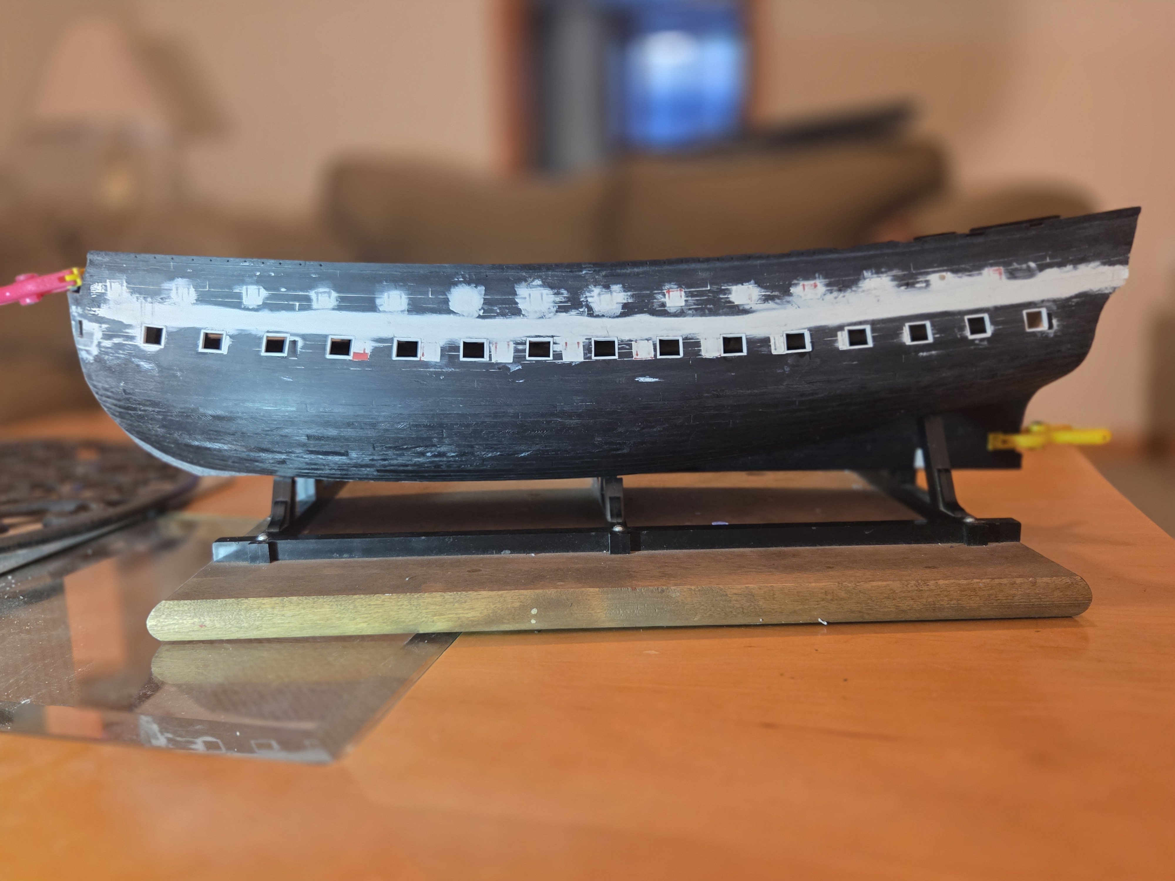
The Lower Gun Deck ports are pierced and framed (#16 is not framed, as I ran out of that size of Evergreen strip!) except for the chase port. I laid the hull down that I started in 1977 for comparison; lacking a chase port, it is pierced for 14 guns. Now on to the port side Lower Gun Deck... when I finish that, the Middle Gun Deck is next. Note that the Lower Gun Deck ports dont have the gun port lid stops nstalled yet... that will narrow them done and have the same dimensions as the kit ports.
.thumb.jpg.f8e41c4f4272aba37dddc4ceec5640fd.jpg)
- 452 replies
-
- 2
-
-
- soleil royal
- Heller
- (and 1 more)
-
Hubac's Historian reacted to a post in a topic:
Soleil Royal 1671 by EricWiberg - Heller - 1/100 - PLASTIC
-
EricWiberg reacted to a post in a topic:
Soleil Royal 1671 by EricWiberg - Heller - 1/100 - PLASTIC
-
Marc, the gun port openings as you see them now are 11.0mm wide x 9.3mm tall, but.... the eventual size will be 10.0mm x 9.3mm tall (I actually cut gun port holes 13mm x 11.3mm, as I wanted to use stiffer 1.0mm stock to frame all four sides of the gun ports, and that framing that you see will indeed be planked over. Final step is I will then installl the 0.5mm wide gun port lid stops (0.5mm on each side, emulating what Andre Kudin did). So the eventual openings will downsize from the current 11mm x 9.3mm that you see down to 10mm x 9.3 mm; at that final size, the spacing between the edges of the gun ports will be 22.5mm.... This seemed to be the best balance of gun port size and spacing to me... in Imperial measurements, that is 39" wide x 36" tall and 7'6' apart in the space I had to fill. I wanted slightly smaller gun ports, but then, of course, the spacing would have to get wide, and so on.
- 452 replies
-
- 1
-
-
- soleil royal
- Heller
- (and 1 more)
-
Hubac's Historian reacted to a post in a topic:
Soleil Royal 1671 by EricWiberg - Heller - 1/100 - PLASTIC
-
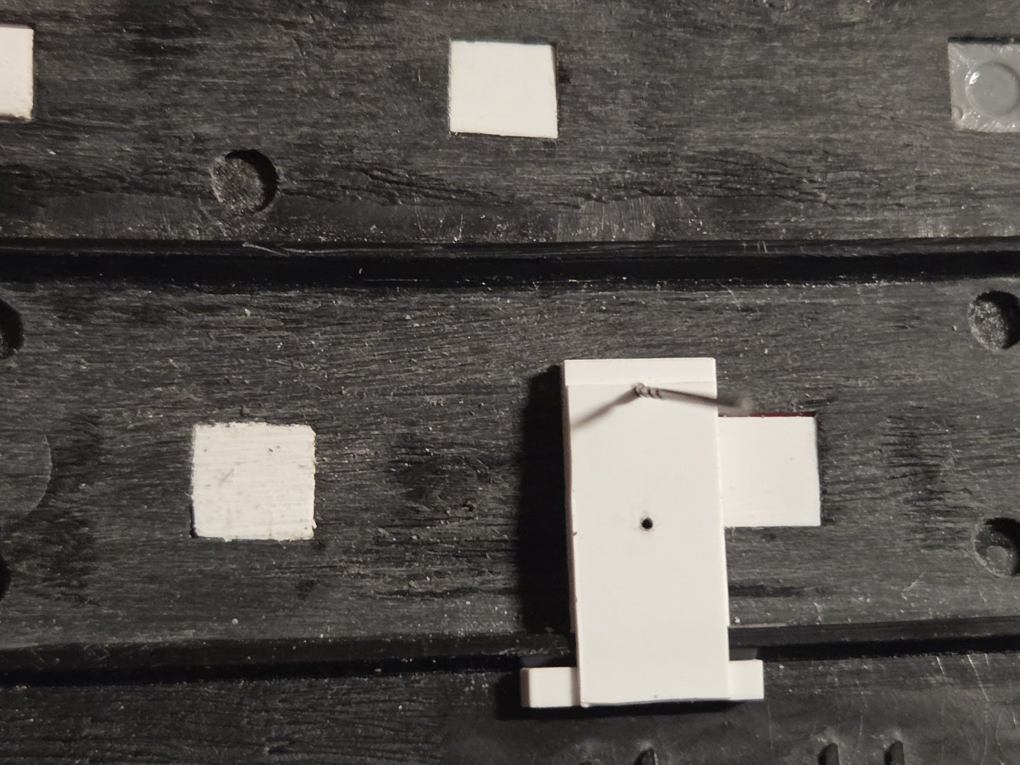
I just finished LD gun port #6, but have been thinking about "trompe-l'oeil"... "decieve the eye", a term I became familiar with after reading Marc LaGuardia's build log. I thought about quarter galleries and the transom, and how do we suggest balconies and structures that seem to be three dimensional, etc., but are not what we think upon closer inspection. What got me thinking about this was gun port #5 (4th port from the right). I would insist to you - I would bet money on it! - that port #5 is obviously out of alignment with the other ports! I fact, I would also argue some of the gun ports have sides that aren't parallel with each other, and are just plain installed incorrectly! But... despite what my eyes see, my laser level and caliper gauge tell a different story. By laying a straight edge above gun ports #3 and #4 and #5, I see the tops of gun ports that are actually in alignment. It all depends on your perspective. If you follow the Lower Deck support ledge from right to left, you see that the tops/bottoms of the gun ports are actually parallel to the deck! And yet when I look at the ship again from the outside, what I see is different than what I know! But I want to believe my eyes.... Hopefully this serves as a lesson, perhaps even inspiration, when dealing with the QG's/transom and utilizing "tromp-l'oeil".... it's all in the perspective!
.thumb.jpg.69b074a1469805fdd67408d36e42a6cc.jpg)
-
Well, because it was -23F this morning when I woke up, and has not gotten warmer than -12F... I just kept working on the ship! After finishing the cutting and framing of the first three Lower Gun Deck gun ports (excluding #1, the chase port, which I will save for last), I was confident enough in my measurements that I marked the centers of gun ports #5 through #16. The positioning looked good, so I gradually drilled the holes out to 8mm. Now it is just a question of cutting and framing them one by one... and I made absolutely sure that I didn't add in a 17th gun port like I did on my paper templates!


- 452 replies
-
- 1
-
-
- soleil royal
- Heller
- (and 1 more)
-
Hubac's Historian reacted to a post in a topic:
Soleil Royal 1671 by EricWiberg - Heller - 1/100 - PLASTIC
-
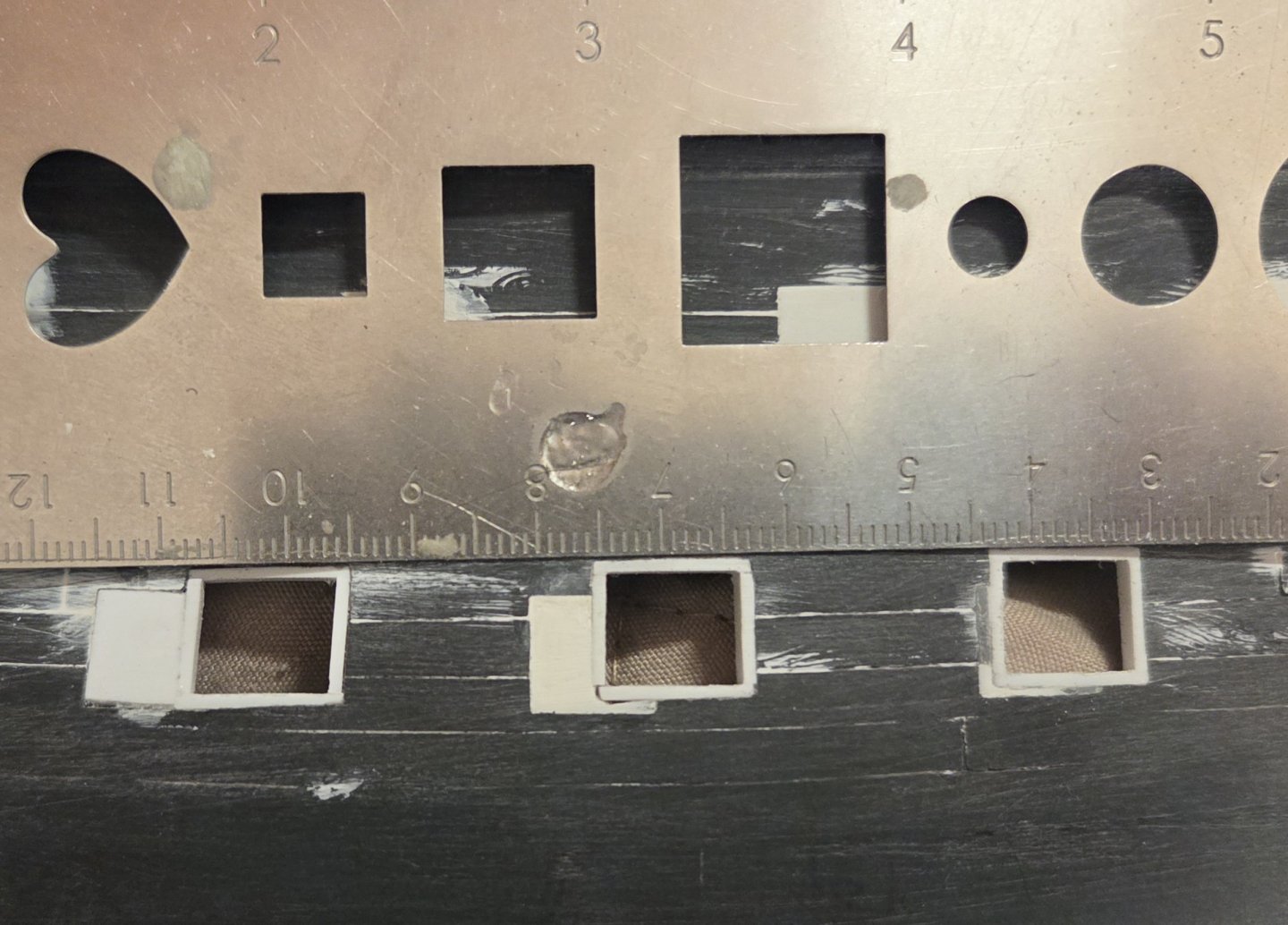
And so the cutting of the Lower Deck gun ports begins... note to self - this is going to take a while! I kept checking my calculations over and over, and was finally satisfied that I hadn't screwed up. My LD ports will be 10.0mm wide X 9.4mm tall. I was going to frame the ports with 0.5mm stock, but I decided that I should use 1.0mm stock, as that would be stiffer.... and I have to account for my gun port sides also having an extra 0.5mm in width due to my gun port lid stops. So... I need to cut ports that are 13.0mm X 11.4mm. I am finding that my laser works better to find the vertical sides of the gun port... i.e. the "plumb line". It is interesting that you can see the parallelogram shape of gun port #2 (on the right). The hull will look distinctly like Frankenstein when I am done, but it will all be covered up by the planking. I am framing each port before I move on to the next one, as I can get the tolerances to 0.1mm before I move on (constantly using the caliper gauge). I will wait until they are all done to use Tamiya putty and light sanding to finish all of the gun ports off together. There is no way around patient cutting with a #11 blade and needle files, but I use increasing size drill bits to try and remove a good amount of plastic at first.


- 452 replies
-
- 1
-
-
- soleil royal
- Heller
- (and 1 more)
-
EricWiberg reacted to a post in a topic:
Soleil Royal 1671 by EricWiberg - Heller - 1/100 - PLASTIC
-
Thanks, Ian. Marc has suggested targeting a gap of 4.5-5.0 feet between the sill of the middle LD gun ports and the top edge of the (lower) bottom wale. At scale, I will be looking at 14.0mm.
-
Hubac's Historian reacted to a post in a topic:
Soleil Royal 1671 by EricWiberg - Heller - 1/100 - PLASTIC
-
Marc, you are absolutely right! I will blame it on getting up at 4am and deciding to do this. I had the proper sizing and spacing for all three gun decks calculated.. and then I ignored that and freelanced as I was completely absorbed in getting the sill heights correct... thanks for pointing that out! Late Entry added 30 minutes after the first post Sigh.. I made a neophyte mistake! My LD gun ports are 9.0mmX8.4MM with 22MM spacing... but I am going to make the holes bigger so I can frame them down to the correct size.... this will narrow my spacing between the gun port edges, of course. So... of course... when I cut out these templates, I used the smaller gun port size, but also used the smaller spacing between gun ports! I knew that I was going to start at kit #2 and end at kit #15... but of course using a smaller spacing block meant that as I kept dutifully filling that available space with gun ports... I created extra space for and additional, unwanted, gun port. Sheesh.....
- 452 replies
-
- 1
-
-
- soleil royal
- Heller
- (and 1 more)
-
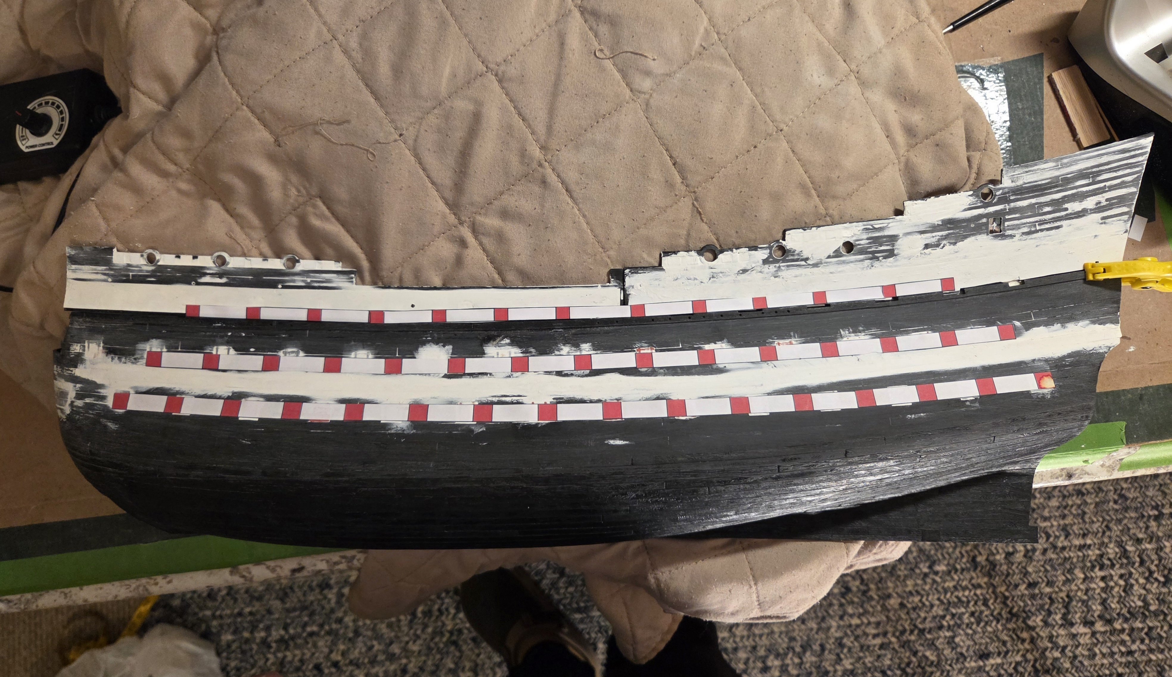
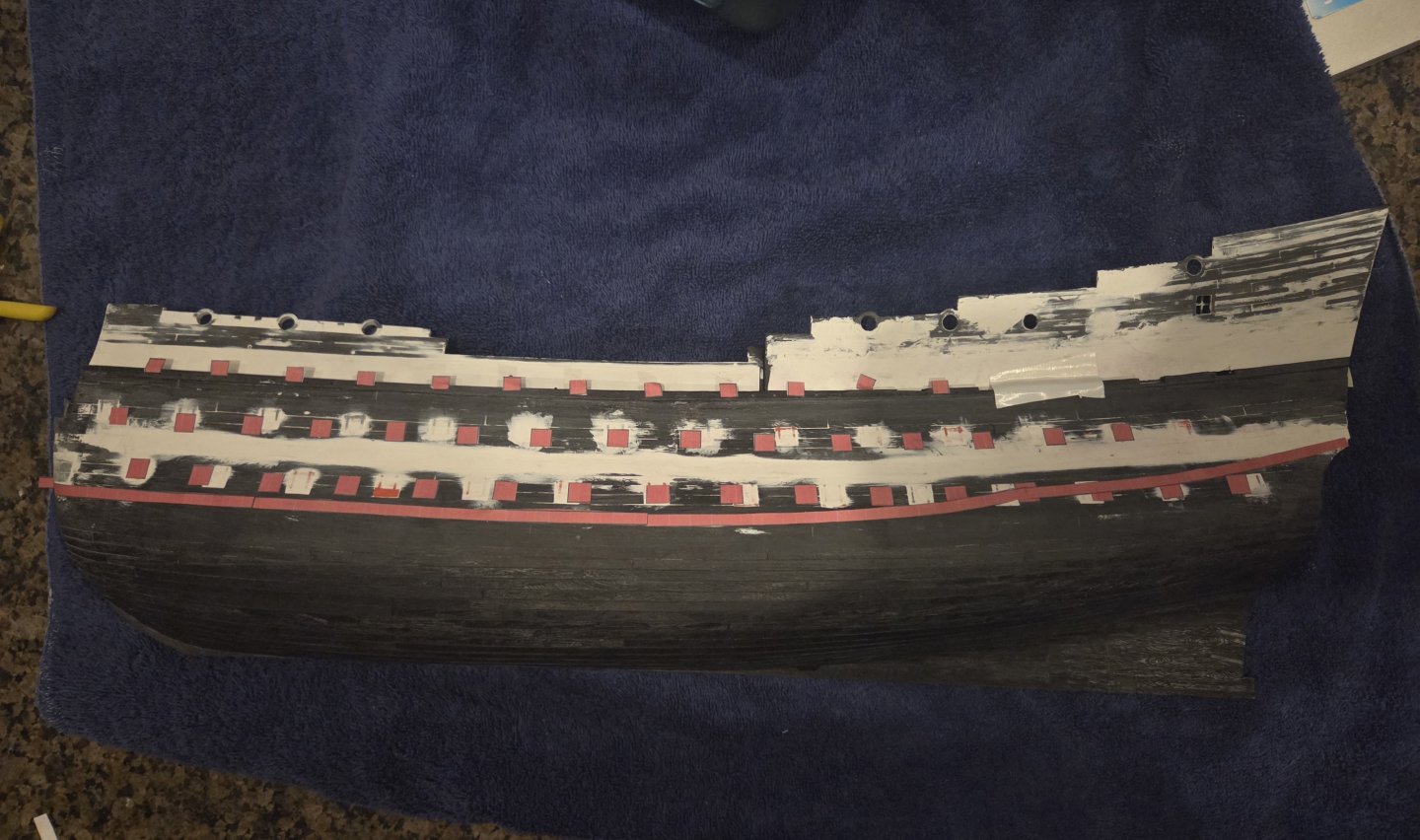
OK, I tried a different approach, cutting out individual gun ports and applying the top bottom wale. It's not perfect by any means, but amazing how the smaller those pieces of paper got, the more they wanted to stick to anything but the hull! Upper Gun Deck #11 is wonky, and I skipped on placing Upper Gun Deck #13. However, the level of the gun ports is pretty consistent from stem to stern and gives me a pretty good idea of what my proposed change in gun port sill heights has done (the bottom wale got a bit... sticky... about Lower Gun Deck #13. To summarize... my LD sills are 0.7mm HIGHER than kit... my MD sills are 2.1mm LOWER than kit... my UD sills are 1.6mm lower than kit. Put another away, on the kit, from the top of the LD gun ports to the bottom of the MD gun ports is between 17-18mm (i.e. an indication of the height between the decks).... on my SR 1671, that distance is 15-16mm. On the kit, from the top of the MD gun ports to the bottom of the UD gun ports is also 17-18mm, and on my SR 1671, that gap is now 15-16mm. In other words, that would suggest I removed 2mm of headroom between the LD and MD, and also the MD and the UD. Of course, that would suggest that I added some headroom at the UD (because I lowered the UD gun ports sills by 1.7mm). However, I am LOWERING the circular gun ports on the forecastle and quarterdeck by 3mm. Hopefully these efforts have made the ship appear a bit more compact vertically... but the key for me is - is my proposed representation of SR 1671 (somewhat) historically accurate?
-
EricWiberg reacted to a post in a topic:
Soleil Royal 1671 by EricWiberg - Heller - 1/100 - PLASTIC
-
The Lower Gun Deck and Middle Gun Deck templates are right about where they should be. The Upper Gun Deck template is a victim of the upper bulwarks being held in by duct tape, so there is a several millimeter gap under most of the front bulwark... but it is pretty close. What is interesting to me - and I don't know that it can be seen - is the difference in gun port sill levels. My Lower Gun Deck sills are 6.5mm, or 0.7mm higher than the kit. However, my Middlw gun Deck sills are 2.1mm lower than the kit, and my Upper Gun Deck sills are 1.6mm lower than the kit. The Lower Gun Deck sill height is what Laurent Hubac apparently used, but I used the rule of 3.5X shot diameter = sill height for the Middle/Upper Gun Decks. This wasn't the main reason governing my sill heights, but I have wondered if my changes might also disguise - a bit? - the overly large kit headroom between the decks. Regardless, I am going to let this it overnight and take a fresh look at the ship in the morning to see if I feel any differently about what am I am proposing to do.

- 452 replies
-
- 1
-
-
- soleil royal
- Heller
- (and 1 more)
-
Marc, I did that for the middle deck.. more paper templates, but... I should also do it for the upper deck ports!
- 452 replies
-
- 1
-
-
- soleil royal
- Heller
- (and 1 more)
-
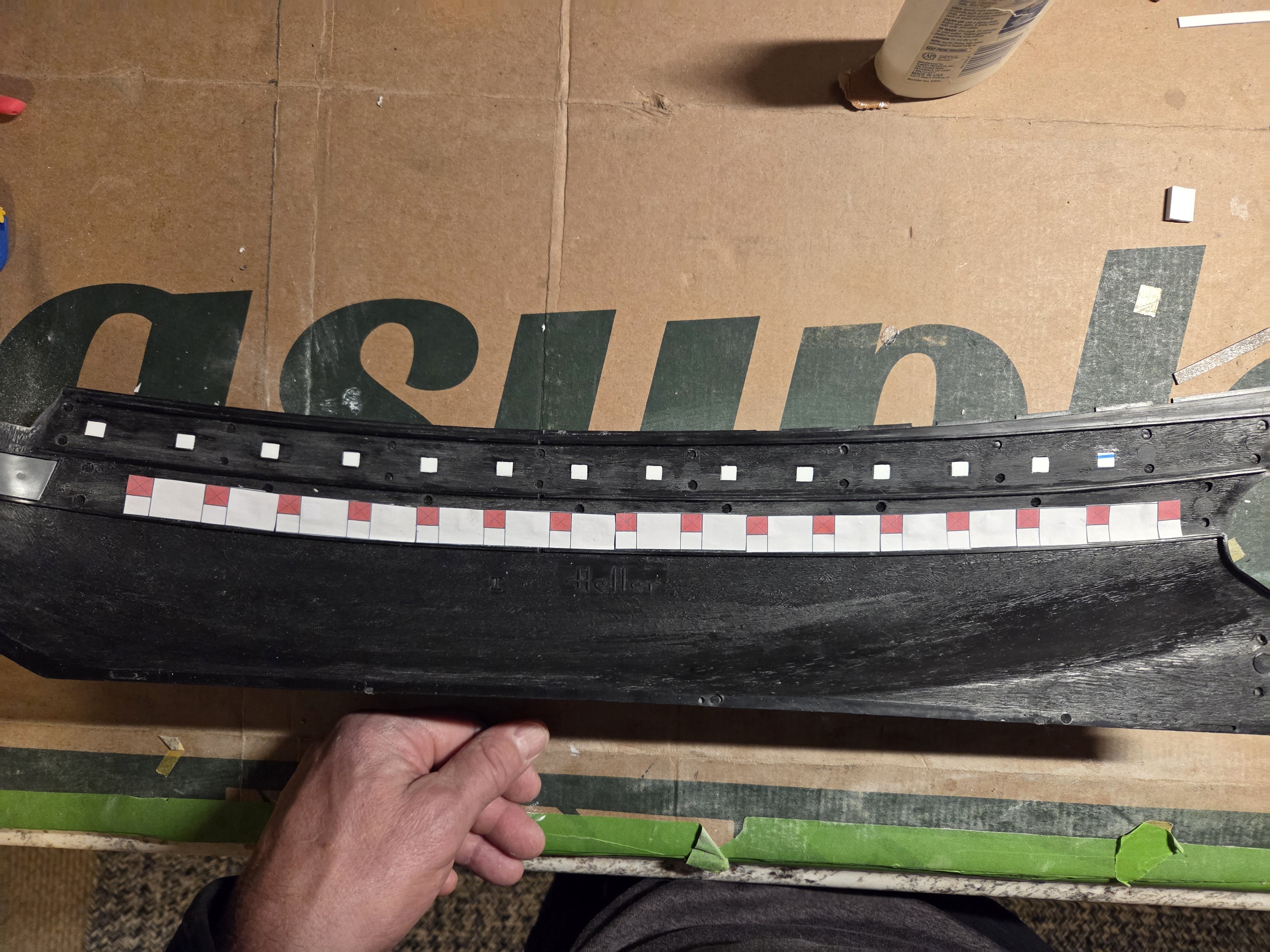
Many thanks, Marc! I am ready to start work on cutting out the lower deck gun ports. I settled on gun ports 9mm wide x 8.4mm tall spaced 22mm apart with sill height of 6.5mm... or in inches, 35.4" x 33.1" spaced 7'2" apart with a sill height of 25'7". I keep seeing that Hubac preferred Lower Deck and Middle Deck gun ports of 32" wide x 30" tall with a sill height of 24" (all in in French inches). I converted those to Imperial Units, and, as Marc has noted several times that I am trying to use 1671 proportions on a Heller kit hull that is based on the 1693 hull, I further multiplied the units by 1.033 (as the 1693 version was 3.3% longer than the 1671 version). I printed out my Lower Deck gun ports and laid them in the inside of the hull.... they visually agreed extremely well with my calculations. You would really have to zoom in on the photo, but every red gun port has a "cross" pattern; so I will start with a small drill bit at every gun port and work my way up. I think it will be possible to just patiently keep going up in a progression of drill bit sizes. Perhaps I can even get up to a bit 6-mm or 7mm in diameter, which means I would have a lot less wasting away of plastic at every gun port. Finally, I made a jig that rides on the inner hull lower deck supports and has holes drilled in so I can scribe lines for the top and bottom of every gun port. That is a an old drill bit in the photo that scribed a line you can barely see, but I would like something sharper - pehaps a sharp sewing needle? The beauty of the jig for me is that as it rides on the deck support rail, it therefore follows the sweep of the deck. So, as they were historically made, the top and bottom of the gun ports were not parallel to the waterline, they were always parallel to the deck. Now, I am not doing this to be historically accurate, but rather I don't have to mess with creating lines that are perfectly parallel to the water line at every gun port. As Marc noted, I will have slight parallelograms instead of perfect squares; historically accurate, yes, but mainly, it will be so much easier for me to just make one scribing pass with the jig! The sides of the gun ports will be perfectly vertical, and I can run those lines off of the old kit gun ports that I filled in.

- 452 replies
-
- 1
-
-
- soleil royal
- Heller
- (and 1 more)


.jpg.ac6ebf954fe89b82c09c9d11b4cdabbc.jpg)
.jpg.bde26bdf900ff3be889020bd019297d0.jpg)
.jpg.67fb401393b993909cd87cd264aabbab.jpg)
.jpg.1bc1e150018f72e940d62c19049d7075.jpg)
.jpg.23488b4e2cece4db08b3811be7dc302a.jpg)


.jpg.b6100c86fb95766858ee1685e6ab9fc0.jpg)