


popeye2sea
-
Posts
1,786 -
Joined
-
Last visited
6 Followers


About popeye2sea

- Birthday 11/09/1961
Recent Profile Visitors
4,310 profile views


-
 Scottish Guy reacted to a post in a topic:
Reef line length...
Scottish Guy reacted to a post in a topic:
Reef line length...
-
popeye2sea reacted to a post in a topic:
Soleil Royal by Hubac's Historian - Heller - An Extensive Modification and Partial Scratch-Build
-
allanyed reacted to a post in a topic:
Reef line length...
-
mtaylor reacted to a post in a topic:
Reef line length...
-
Keith Black reacted to a post in a topic:
Reef line length...
-
Falconers Dictionary of the Marine notes that reef points are nearly double the circumference of the yard. That is the total length of the reef point, half lying before the sail and the other half aft. Regards, Henry
-
Keith Black reacted to a post in a topic:
Cutty Sark mizzen pin rail belaying pins and mizzen halliards
-
mtaylor reacted to a post in a topic:
Cutty Sark mizzen pin rail belaying pins and mizzen halliards
-
mtaylor reacted to a post in a topic:
Revell H-364:995 (1959)
-
 To be honest, I don't see the problem. The photo of your model is a bit out of focus there but it looks like there are 8 pins in the shear pole and another 9 in the pin rail spanning the entire gang of shrouds and backstays. That is exactly the call out in Underhill for all of the lines that belay here including the mizzen upper topsail, mizzen lower topgallant, mizzen upper topgallant, and mizzen royal halliards. Your spanker outhauls should belay on the monkey rail at the base of the mizzen. There is no mizzen halliard. The crojack yard is fixed, as is the mizzen lower topsail. Regards, Henry
 -
Canute reacted to a post in a topic:
Revell H-364:995 (1959)
-
Scottish Guy reacted to a post in a topic:
Revell H-364:995 (1959)
-
I built this kit in the late 70's. It makes a good looking model. Your answer depends on what your plans are for this build. Do you intend to build it straight from the box, or are you going for a bit more accuracy? If I were to build this again I would not be using any of the rigging thread or the sails, and replacing many of the plastic spars. The sails on these old kits will probably be yellowed and brittle and the rigging thread is not very good. Most of the rigging on these clippers was wire rope anyway. Likewise, the molded shrouds and ratlines will need to be thrown out. Forget about the paints, they would probably be solid bricks by now. The decals will also be off colored and brittle. Bottom line, if the hull moldings and other major parts are in good shape and not warped, I would not worry too much about the above items. You were going to end up replacing them anyway. Regards, Henry
-
Canute reacted to a post in a topic:
replacing plastic mast and spars
-
replacing plastic mast and spars
popeye2sea replied to Frank Burroughs's topic in Plastic model kits
Description of how to make a 90 deg. channel; 45 deg. L and 45 deg. R cuts. Henry -
popeye2sea reacted to a post in a topic:
NRG Rigging Project by tlevine
-
popeye2sea reacted to a post in a topic:
Soleil Royal by EricWiberg - Heller - 1/100 - started 45 years ago
-
popeye2sea reacted to a post in a topic:
HMS Victory by dafi - Heller - PLASTIC - To Victory and beyond ...
-
I have no idea when that photo was taken, but I do know that it was not 1797. I mention the launch date of the ship for reference to what period she depicts. As far as looking fake goes, I can tell you that Constitution, as much as she can, adheres to historical accuracy. That being said, there are several caveats. The first being, accurate to what period? She has been an active Naval vessel for 227 years. There have been many changes made over those years. She tries to adhere to her appearance during the war of 1812, but a discerning eye can spot many anachronisms. There are also concerns about the costs of maintaining the vessel. It is prohibitively expensive to maintain the ship using live oak, hemp rigging, and flax sails. Modern materials are substituted. For instance, the shrouds are composed of a manmade material that looks like hemp around a steel core. The sails are also a modern material that looks like canvas. Those breeching ropes do look to be too short to be functional and the first seizing is a round seizing whereas I think it should have been a throat seizing. But, I am no expert. Then again, those guns have never been fired and they never will. But they do give the correct impression of what things looked like back then. Sorry for the rant. I am passionate about my ship. Henry
-
USS Constitution 1797 Regards, Henry
-
Looking at the diagram you posted and noting the angles at which the lines lead. My opinion is that this topsail halyard is set up as a runner and tackle arrangement with the standing part of the runner (on the left side) leading down to an eyebolt on the port side of the ship and the halyard fall leading down to the knight where the standing leg would be fastened to an eyebolt and the running end passed through the sheave and belayed. The fore topsail halyard would probably have been rigged opposite, with the runner leading down to the starboard side. Regards, Henry
-
popeye2sea reacted to a post in a topic:
Soleil Royal by Late To Soleil - Heller - 1:100 - PLASTIC
-
Long lasting paint
popeye2sea replied to GrandpaPhil's topic in Painting, finishing and weathering products and techniques
My plastic build is going on 45 years. I use acrylics; Tamiya, Model Master, Vallejo, etc. I have never had to repaint anything. Regards, Henry -
The most complete source is THE ASHLEY BOOK OF KNOTS by Clifford Ashley. Other good sources are THE ARTS OF THE SAILOR by Hervey Garrett Smith and THE YOUNG SEA OFFICERS SHEET ANCHOR by Darcy Lever Regards, Henry
-
Rigging Cutter Square Sail Sheets and Tack
popeye2sea replied to Thukydides's topic in Masting, rigging and sails
That's one of the oddest arrangements I have ever seen. I would have suspended the topsail from the topmast and just have the foot of it spread from the regular main yard. The extra lower yard to spread the foot of the topsail is totally unnecessary and then there would be virtually no gap between the topsail and the main square sail. That would make the topgallant sail unnecessary also. Regards, Henry -
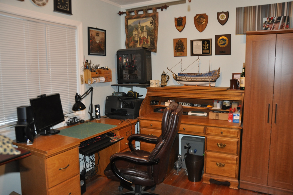
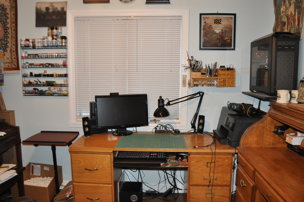
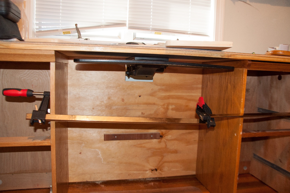
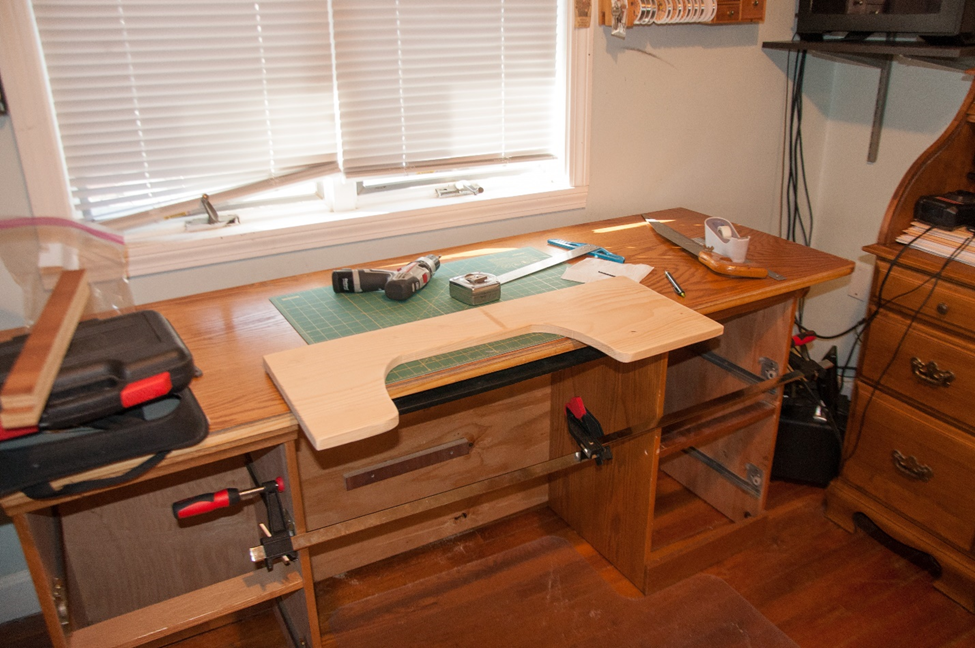
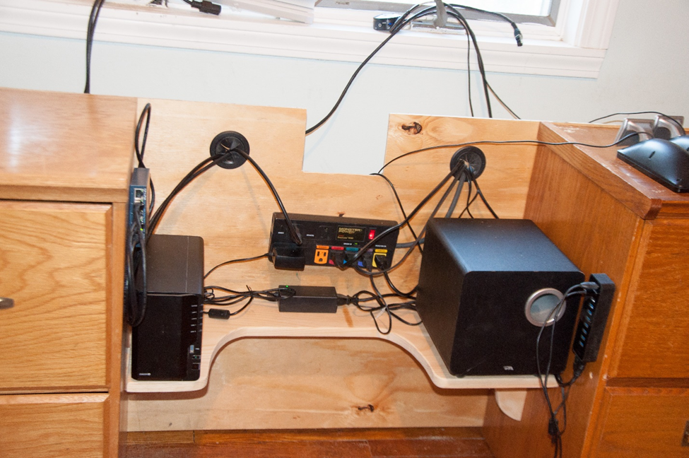
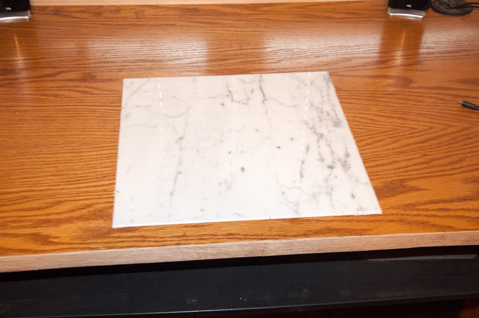
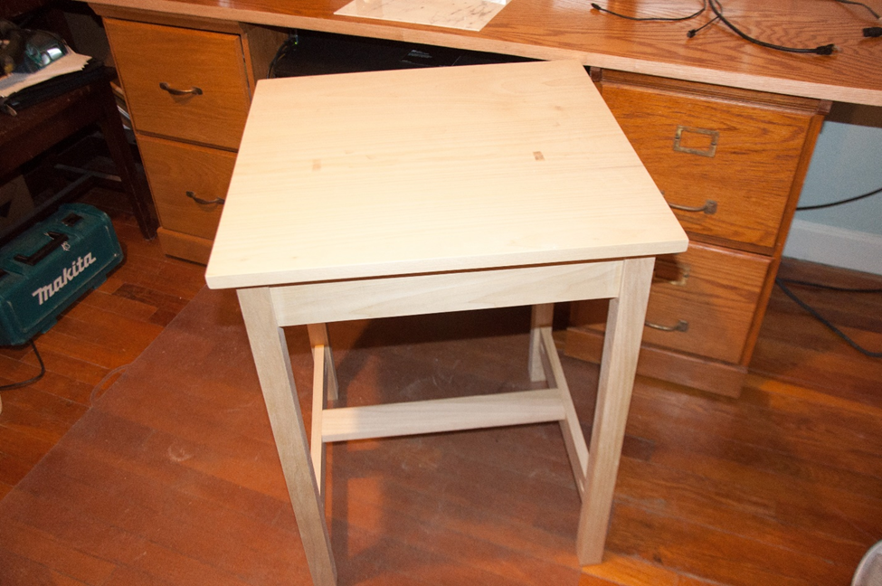
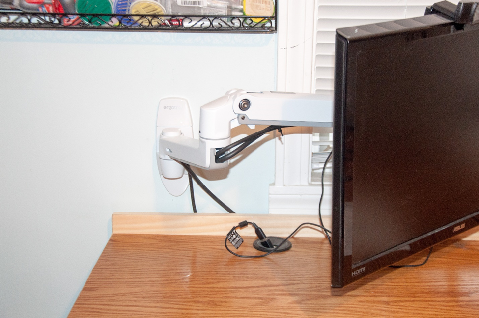
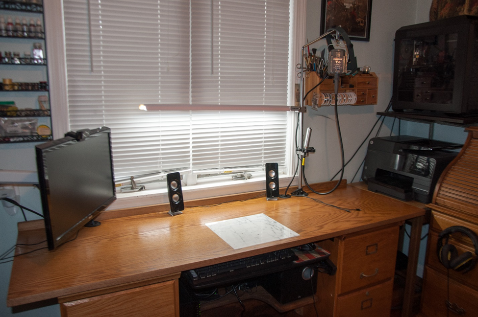
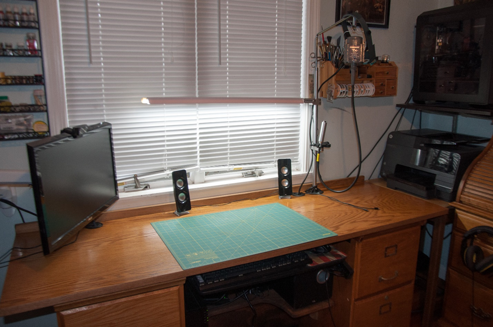
Hard to believe, but once again it has been ages since I last did anything with this build. Last time I actively worked on this was 2018. Six years gone. That has not stopped me from thinking ahead and planning the next steps. though. Part of what I have been planning has been an upgrade to my little shipyard/workspace. Let me tell you a story. Upgrading the Shipyard Several years ago, I knocked together a workspace to use for ship modeling as well as home office use. It consisted of two 2-drawer filing cabinets and a six-foot wood work surface laid over the top. It sufficed for many years, but it had several short-comings. There was a certain lack of stability, no way to level the surface, cable management was a problem, and various pieces of equipment and electronics ended up on the floor of the knee hole or on the floor behind the workstation. In addition, the computer monitor, printer, and other items took up valuable work area in an already very small workspace. The cheap edge banding I had applied to the original work top had also begun to peel off. I also did not like the way the keyboard tray was mounted. When pushed all the way in the front edge protruded further from the front of the top allowing stuff to fall down from the worktop directly into the keyboard. A few months ago, a part of my Dremel tool broke. Instead of buying the replacement part I decided to splurge for an upgrade. I purchased a Foredom Tx flexible shaft motor and handpiece. I took the opportunity, while my Soliel Royal model was entered into this year’s model show, to do the work to upgrade the shipyard. Step one was to connect the two file cabinets into a proper rigid desk base. This was accomplished by fastening a piece of quarter inch plywood as a back and fitting a shelf between the cabinets to hold all the electronic equipment that used to be on the floor. Adjustable levelling feet were added to each filing cabinet. The ¾ inch shelf rests on a cleat attached to the back board and a bracket on each cabinet. The back board was pierced with 2-inch holes for cable management. Notice in the pictures the jury-rigged clamps. There was a slight bow in the plywood backboard which caused the front of the cabinets to splay out wider in the front. I had to draw them back in to fit the shelf properly and I did not have a clamp that was long enough. Step two dealt with the work surface. The old edge banding was stripped off and a 1 x 3 poplar board was applied to the back edge to act as a back stop preventing stuff from rolling off the back edge of the table into the mysterious parts black hole that seems to form in every modeler’s workspace. The top was also pierced with 2-inch cable management holes and new better quality edge banding was applied to the front and sides. I had been using a 12 x 12 sample granite tile as a sort of heat shield when I did my soldering. When not in use the tile lived under the desk. I decided this upgrade would include insetting the tile into the surface of the work top so that it would be flush with the top. A cavity was routed into the desktop to take the 3/8 inch tile. I also cut a 2-inch hole up from underneath the desk into this cavity to be able to push the stone up from the bottom for removal when required. It all seemed to be working out perfectly until the stone cracked while trying to fit it the first time. So, another trip to the tile store where an identical sized marble tile was found to replace it. Both tiles only cost some smiles and friendly conversation. You know…schmoozing. Step three consisted of constructing a new printer stand/table to free up valuable worktop real estate. The table is made from poplar. I bought three 6-foot boards; 1 x 3, 1 x 4, and 1 x 10. and a length of 2 x 2 poplar for the legs. The 1 x 10 was rough cut into three parts and edge jointed and glued up for the top. The 1 x 4 was used to make the aprons and the 1 x 3 went into the stretchers for the legs. Construction of the printer table took 2 days: one for the cutting, assembly and rough sanding, and the second for finish sanding, stain, and polyurethane top coats. This is nowhere near fine furniture grade stuff. The final act was assembly. Wooden cleats were fastened under the desktop to position and hold the desktop in place on the file cabinets. Plastic cable management grommets were placed into their holes. A power strip was mounted on to the base back board. The Ethernet hub was mounted on the left file cabinet and a USB hub was mounted on the right file cabinet. The network storage drive and the speaker system were placed on the under-desk shelf. A new swing arm wall monitor mount was mounted above the left side of the desk. The stand for the Foredom drill is mounted to the top of the desk. This stand also includes as an add on feature a light kit that turns on by swinging the light down from vertical to horizontal. The printer was moved to its new home on the printer stand to complete the project. And there you have it. I just brought the build back home today from the model show and I am feeling inspired to continue along on this build. Thanks for looking in. Regards, Henry
- 196 replies
-
- 3
-
-

-
- plastic
- soleil royal
- (and 2 more)
-
Did 18th and 19th century ships have flat weatherdecks?
popeye2sea replied to Rushdie's topic in Nautical/Naval History
Flat decks would be a problem for wooden ships. Flat decks leads to standing water. Standing water leads to water infiltration. Water will always find a way in. Fresh water infiltration leads to death for wood ships. It doesn't take much camber for a deck to be effective at shedding water. You may not even notice it. Regards, Henry -
Parts identification in Soleil Royal kit
popeye2sea replied to Late to Soleil's topic in Plastic model kits
I believe those are defects left over from the mold process. There are no parts that go there. Regards, Henry -
I would also go with the 'under' method depicted on the left. Regards, Henry
-
My edition of 'Spritsail Topmast' has the information for deadeyes in the section for the standing rigging of the fore and main mast starting on page 93. Regards, Henry
