Ikcdab
-
Posts
31 -
Joined
-
Last visited
Recent Profile Visitors
196 profile views

-
 GrandpaPhil reacted to a post in a topic:
Steam Tug Wattle by Ikcdab - 1:24 - my first scratchbuild
GrandpaPhil reacted to a post in a topic:
Steam Tug Wattle by Ikcdab - 1:24 - my first scratchbuild
-
mtaylor reacted to a post in a topic:
Steam Tug Wattle by Ikcdab - 1:24 - my first scratchbuild
-
Thanks to @KeithAug @druxey and @wmherbert for your helpful advice. I'm not sure how I avoid bending "in the wide direction" as it seems essential to me that the first plank should follow the line of the deck. With regards to my previous question about appropriate planking width, I realise that they don't all have to be the same width....I will get the table saw going tomorrow and cut planks in 6, 7 and 8mm widths and see how it goes .. Thanks again
-
oakheart reacted to a post in a topic:
Steam Tug Wattle by Ikcdab - 1:24 - my first scratchbuild
-
Landlubber Mike reacted to a post in a topic:
Steam Tug Wattle by Ikcdab - 1:24 - my first scratchbuild
-
Valeriy V reacted to a post in a topic:
Steam Tug Wattle by Ikcdab - 1:24 - my first scratchbuild
-
Valeriy V reacted to a post in a topic:
Steam Tug Wattle by Ikcdab - 1:24 - my first scratchbuild
-
mtaylor reacted to a post in a topic:
Steam Tug Wattle by Ikcdab - 1:24 - my first scratchbuild
-
Harvey Golden reacted to a post in a topic:
Steam Tug Wattle by Ikcdab - 1:24 - my first scratchbuild
-
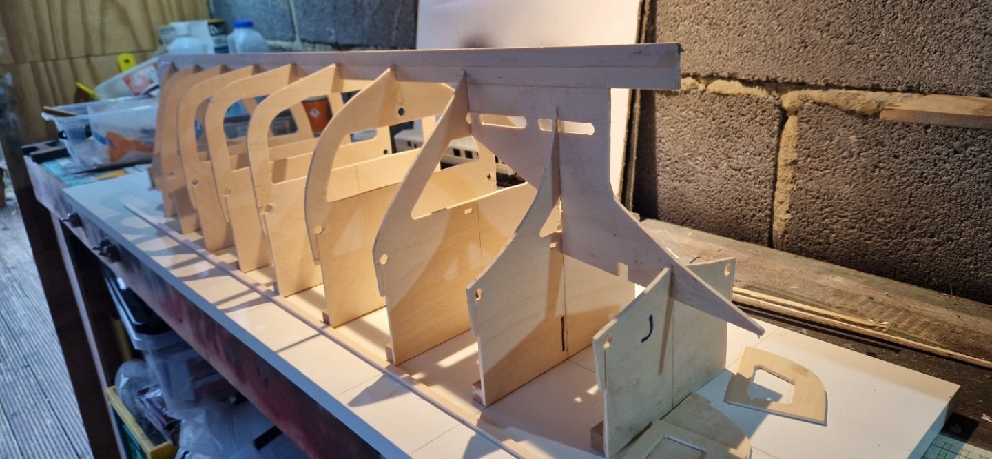
Bulkheads all now fixed to building board, keel made up and we are ready to start planking. I have, of course, watched endless youtube clips about planking, so I am soaked in how to do it....but confused by the variations - everybody has their own methods. So, what are the top tips for planking? The designer says to start at deck level and lay in a few planks either side of that. The lay in planks from the garboard and fill in the gap. Is that the best way?

-
GrandpaPhil reacted to a post in a topic:
Steam Tug Wattle by Ikcdab - 1:24 - my first scratchbuild
-
GrandpaPhil reacted to a post in a topic:
Steam Tug Wattle by Ikcdab - 1:24 - my first scratchbuild
-
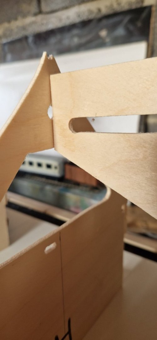
I have come across a snag. I have cut out the bulkheads exactly as per the drawings. When I assemble them, I have a mismatch between the hole for the propellor tube on the final bulkhead and where the cutout (slot) is on the keel section. See picture below When I measure it on the drawings, I see the mismatch. There is a 8mm discrepancy, the diameter of the hole. I don't see how I can change the slot because of I move it down the propeller will no longer fit. All I can think of doing is to fill the holes in the bulkheads and refill them too match the slot. Then I'll need to shim the motor so that the shaft matches the redrilled holes. Any thoughts?
-
Hi Keith, thanks. We shall see. Luckily I can back out and change things if it doesn't work out. As you say, I said I was using balsa right up front and all the advice on here was not to, despite that being what the original designer used. I do have plenty of clamps, we shall just have to see how it goes. I guess narrower planking will be easier than wider in that case. Ian
-
Hi Keith, as per the plans I am building it from, the bulkheads are spaced 95mm apart. I am planking it with 3mm thick planks, again as per the drawings.
-
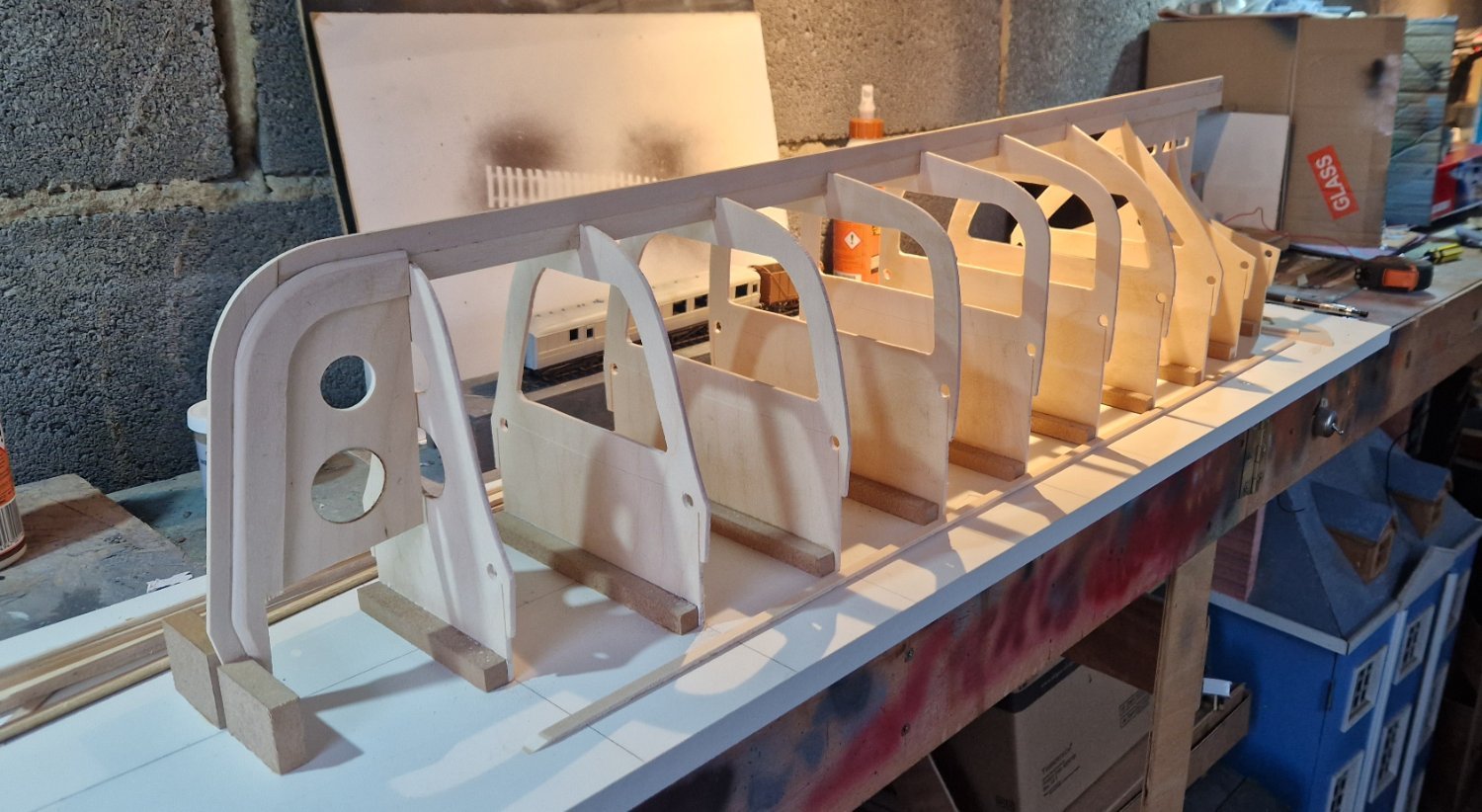
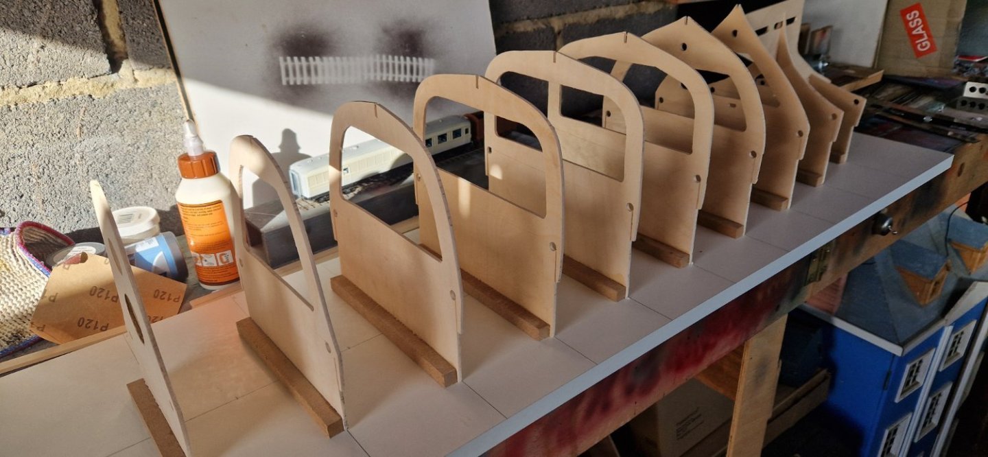
So I have now cut out all of the bulkheads. Just temporarily stood up....
-
Hi Bill that's very interesting, thanks.
-
Hi Roger, thanks. Is "spiing" the correct term? Google doesn't help me with that! The strip approach seems promising, I guess narrower strips are easier to form around the shape of the hull. Ian
-
Excellent. Very useful. I found that gentle heat from a hairdryer was sufficient to soften the prittstick such that it just peeled off.
-
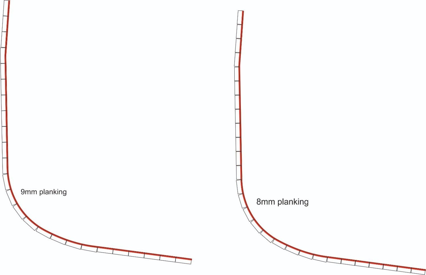
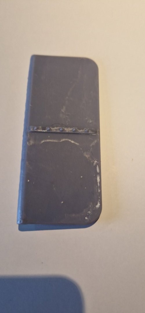
So the reprint was successful. I now have a straight, unwarped rudder. Ill upload a picture tomorrow. Meantime i am still cutting out bulkheads. So a question, how do i decide the width of the planking? The drawings are silent on this, so its a bit of guess work. The longest length from the gunwale to the keel is about 270mm. here is a drawing showing 8mm and 9mm planking. I guess that where the sides are flat then its immaterial, but more important arouind the turns, and also where the planks bend around the stem and stern. My temptation is to go for 8mm planking, Any advice gratefully received.
-
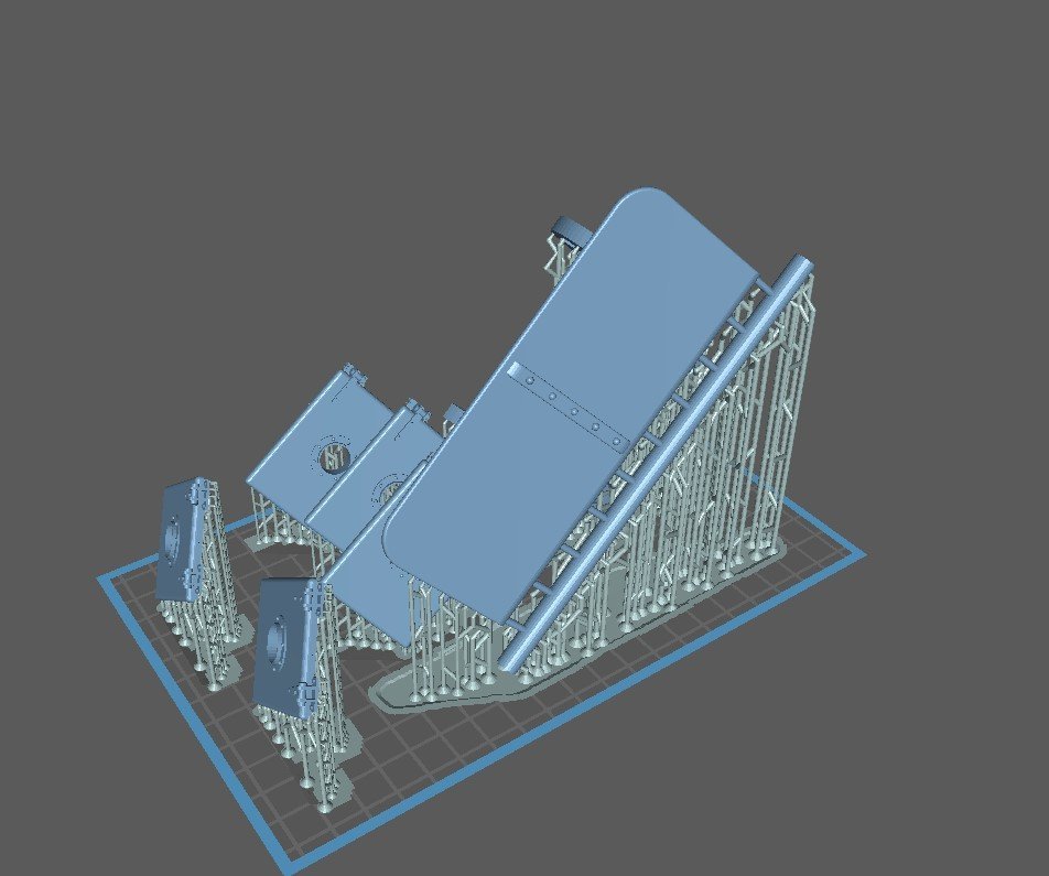
So tonight I am going to reprint the rudder. The screenshot below shows that I have added a sacrificial "sprue" along the bottom edge in order to try and keep the rudder from warping on the build plate. You can also see that I am going to print the remaining hatches and, hidden behind the rudder, is the motormount. Its a 9 hour print, so Ill run it overnight. Lets hope this one is more successful....
-
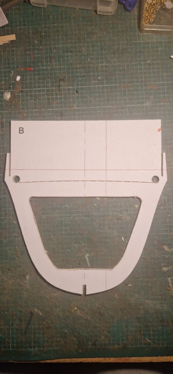
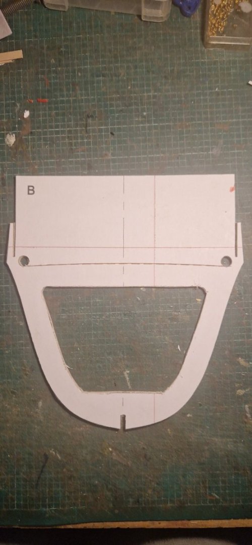
And I have also started cutting out the bulkheads.... This is the first one. The top edge is sacrificial and once the planking is complete, gets get off along the curved dashed line. The instructions say to "score this line" which I have done, probably cutting half way through. I am apprehensive as to how easy it's going to be to release the hull from the building board in this way. Anyone got any experience of this?
-
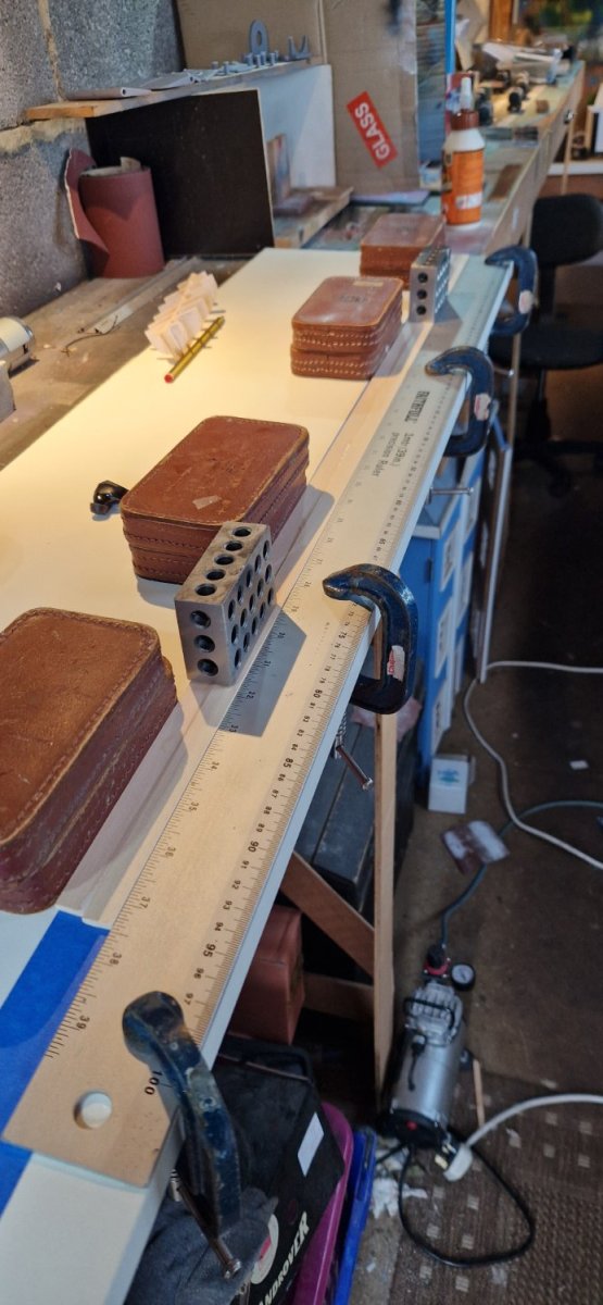
And so to actual construction. The keel is 25mm x 3mm basswood, but I could only buy 12.5mm x 3mm, so I have just to laminate two bits together. I was concerned to get these true, they are 950mm long. You can see the setup I used to get these glued true. I fastened down a 1m straight edge to my building board and held the wood tight with weights. I held the wood flat with some 123 blocks. Glue now drying.

-
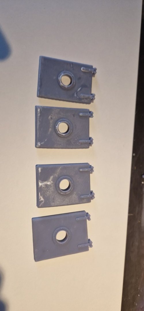
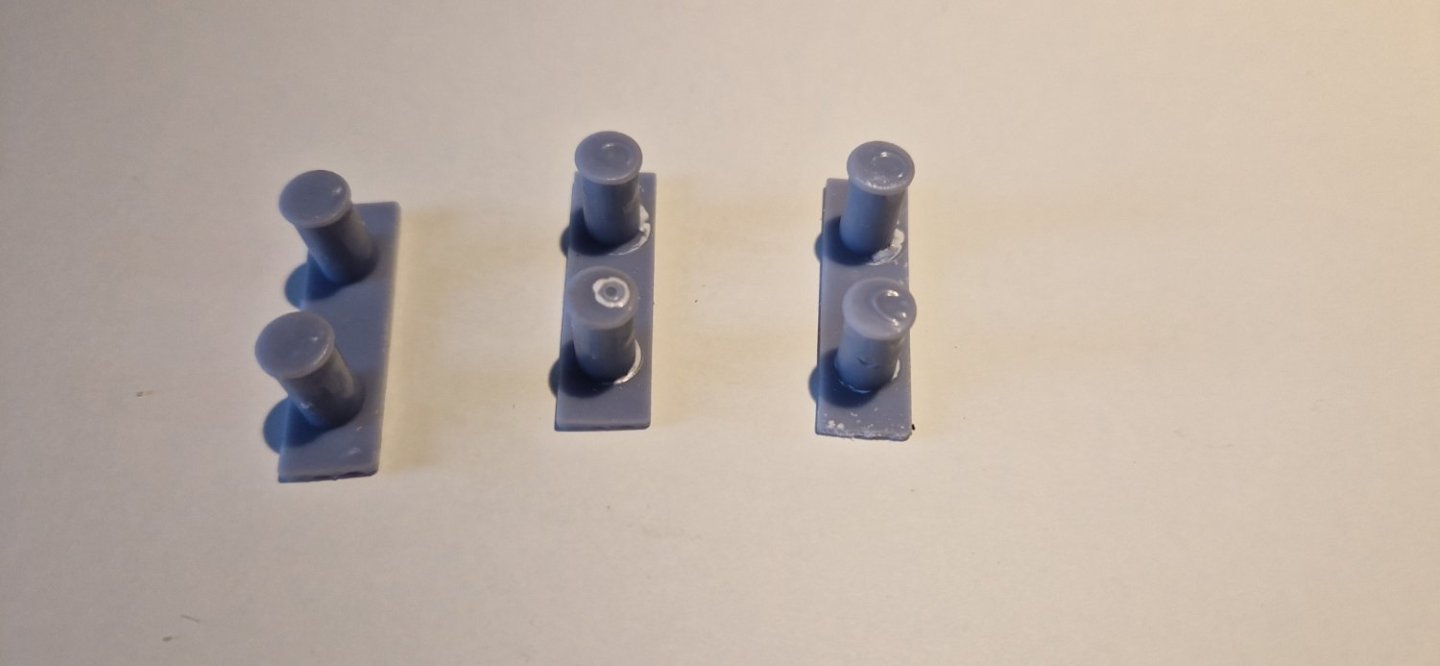
So some progress. I think I can 3d print many of the fittings for the boat. I very much enjoy using fusion360 and I have used this to design a number of features. I have now printed some. Below are the double bollards: And here are engine room hatches with portholes built in. And a failure. This is the rudder, but it has warped while printing. So I now need to reprint it, bit with additional supports to keep it true. The bend you see is not an optical illusion... I have also designed funnel, portholes, skylight, vents etc. But not printed them yet. More to came later. Ian
-
Hi Roger thanks, I am not familiar with any of those sort of calculations and i know nothing about the motor's torque curve, the prop geometry or the hull resistance. Do people really make all of those sort of calculations for a model boat? if so, where do i find the info? Bearing in mind its a 12v motor, if i link it up to 7.2v NiMH 5ampere batteries, then that should give slower revs and a reasonable duration?