


MisterMeester
-
Posts
86 -
Joined
-
Last visited


-
 king derelict reacted to a post in a topic:
RMS Titanic by MisterMeester - Trumpeter - 1/200 - PLASTIC
king derelict reacted to a post in a topic:
RMS Titanic by MisterMeester - Trumpeter - 1/200 - PLASTIC
-
 king derelict reacted to a post in a topic:
RMS Titanic by MisterMeester - Trumpeter - 1/200 - PLASTIC
king derelict reacted to a post in a topic:
RMS Titanic by MisterMeester - Trumpeter - 1/200 - PLASTIC
-
yvesvidal reacted to a post in a topic:
RMS Titanic by MisterMeester - Trumpeter - 1/200 - PLASTIC
-
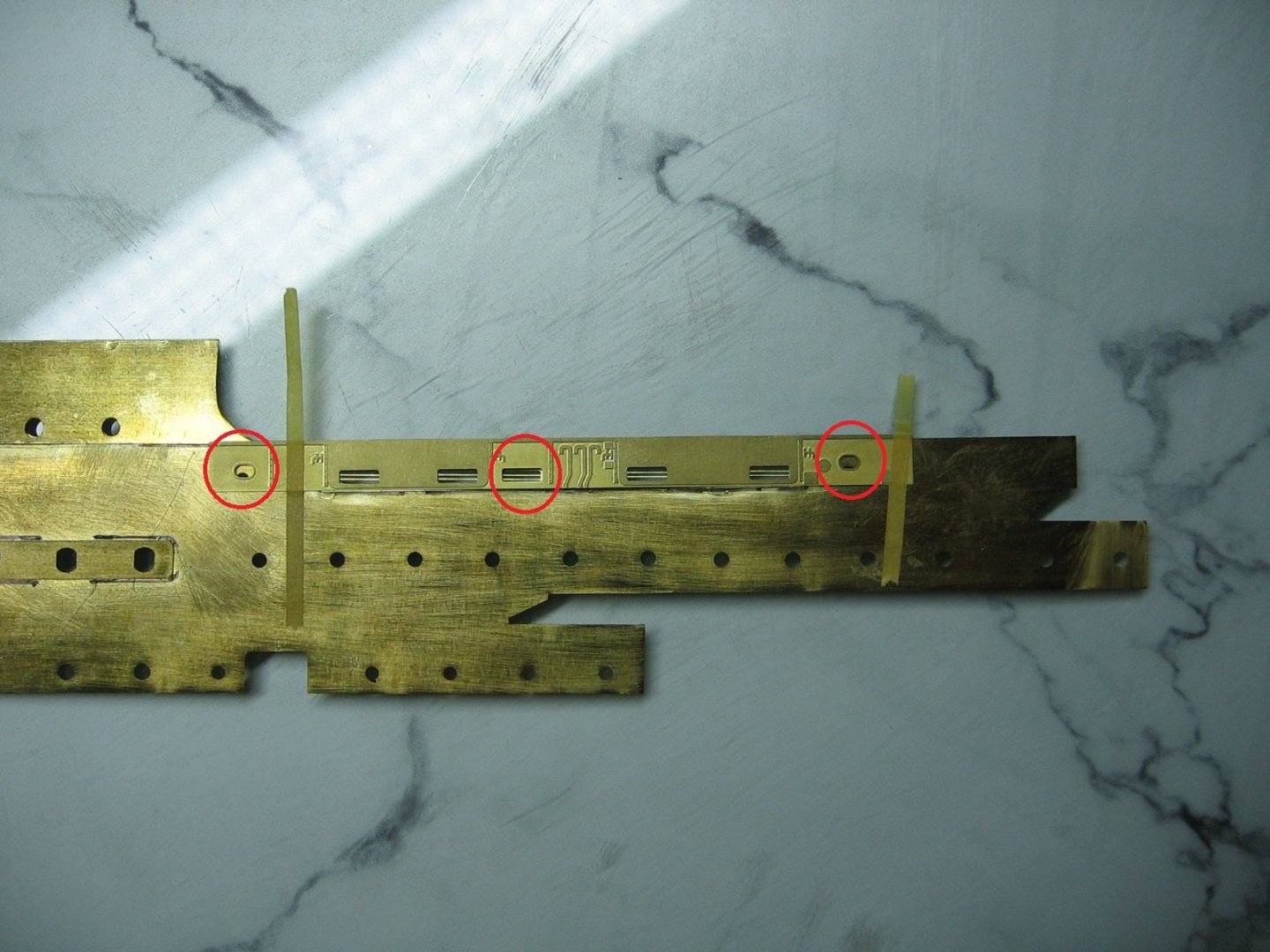
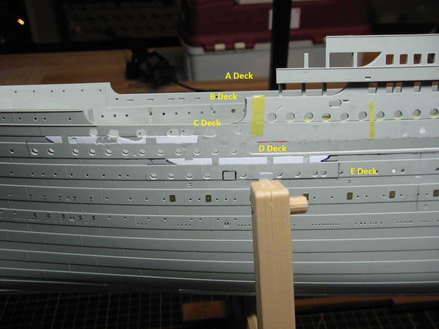
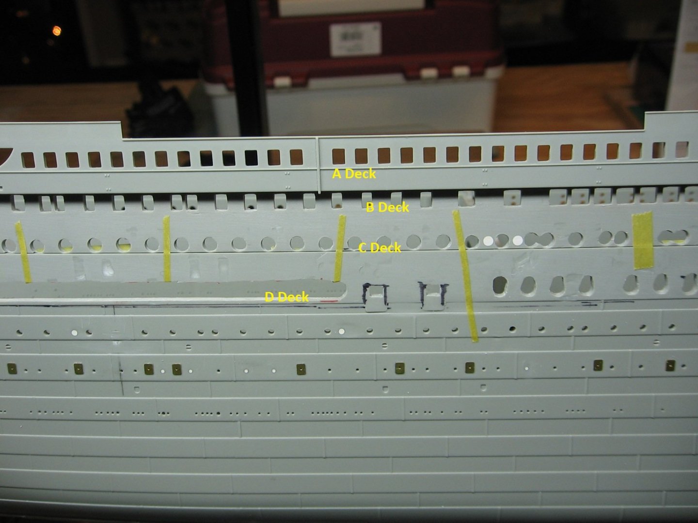
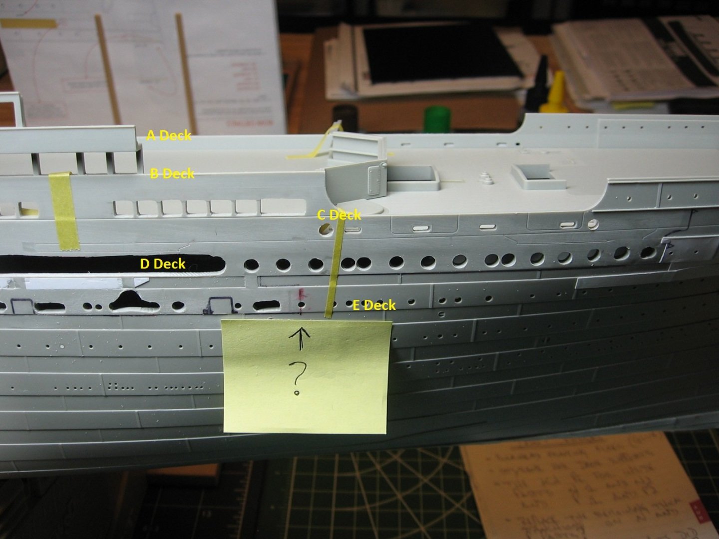
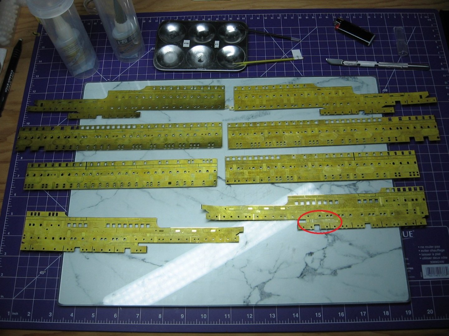
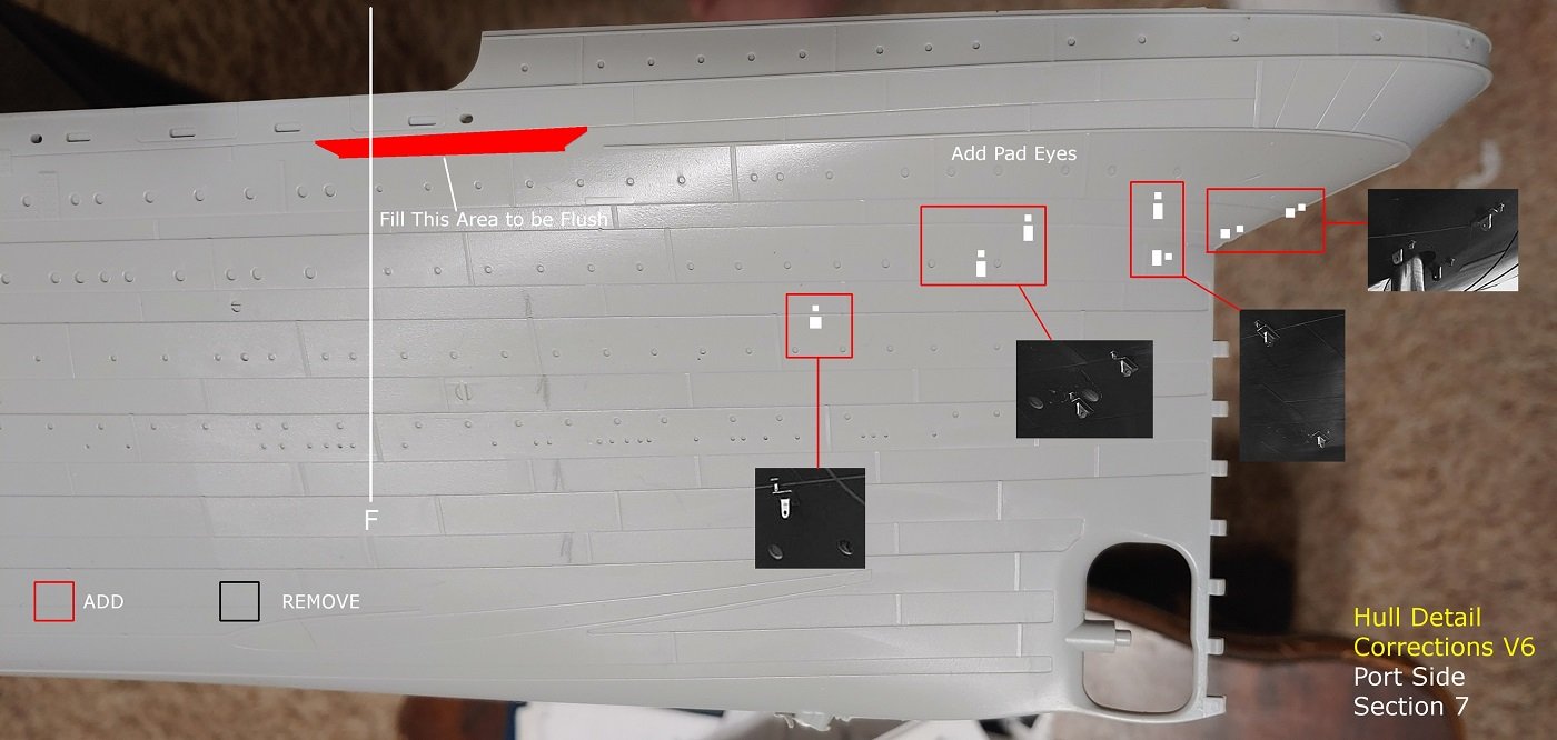
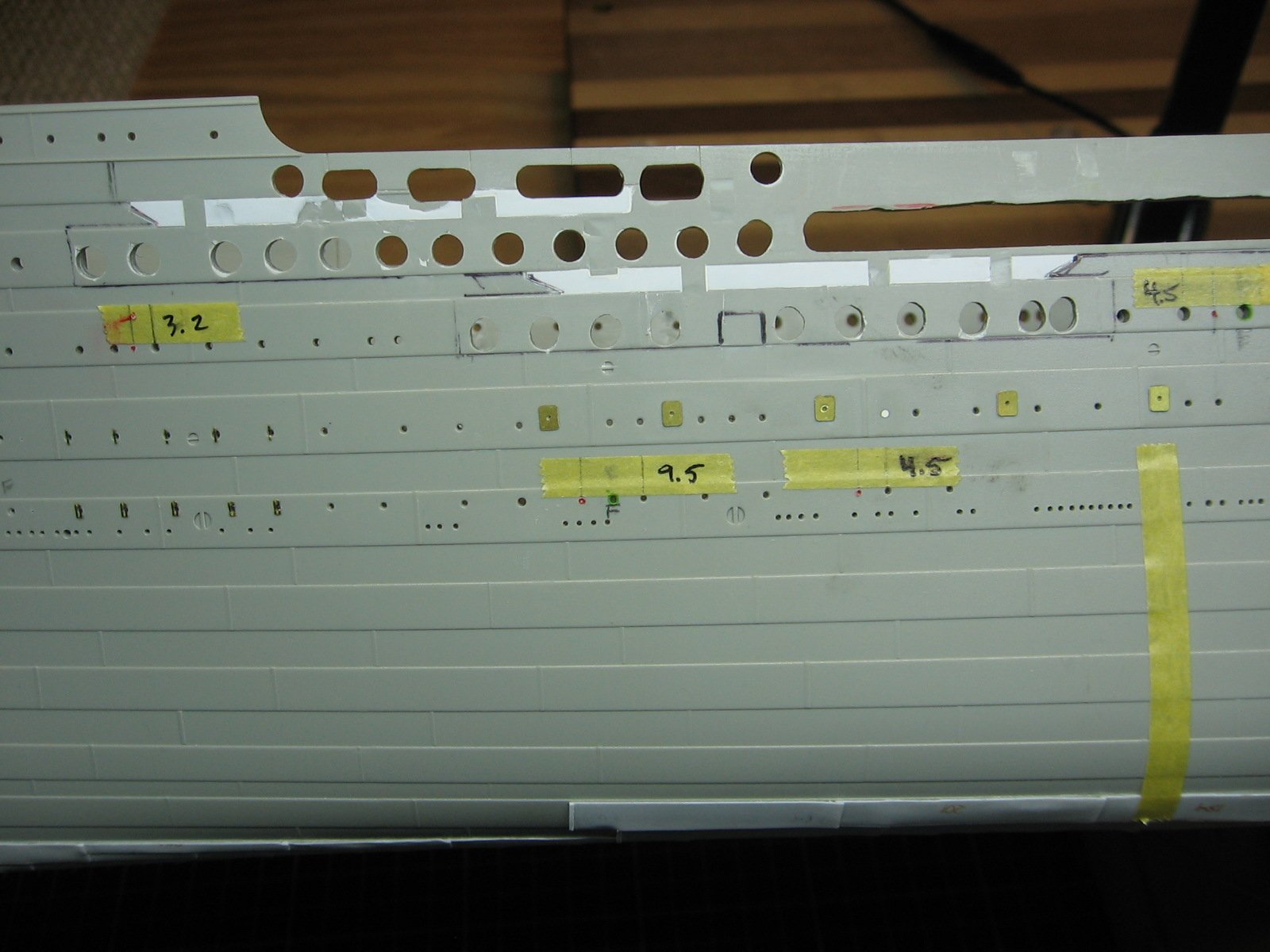
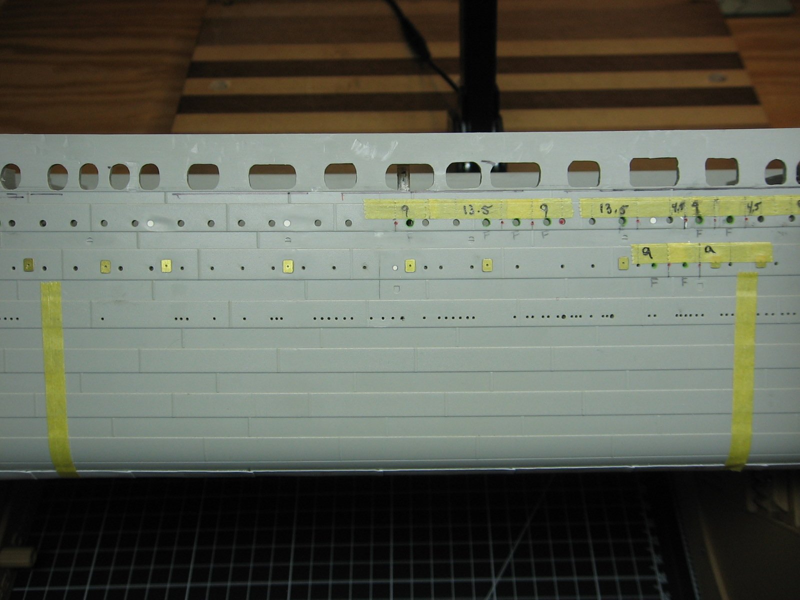
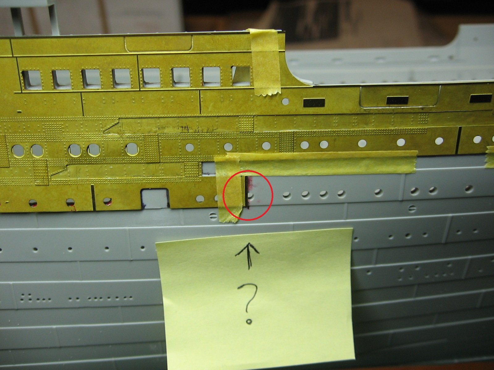
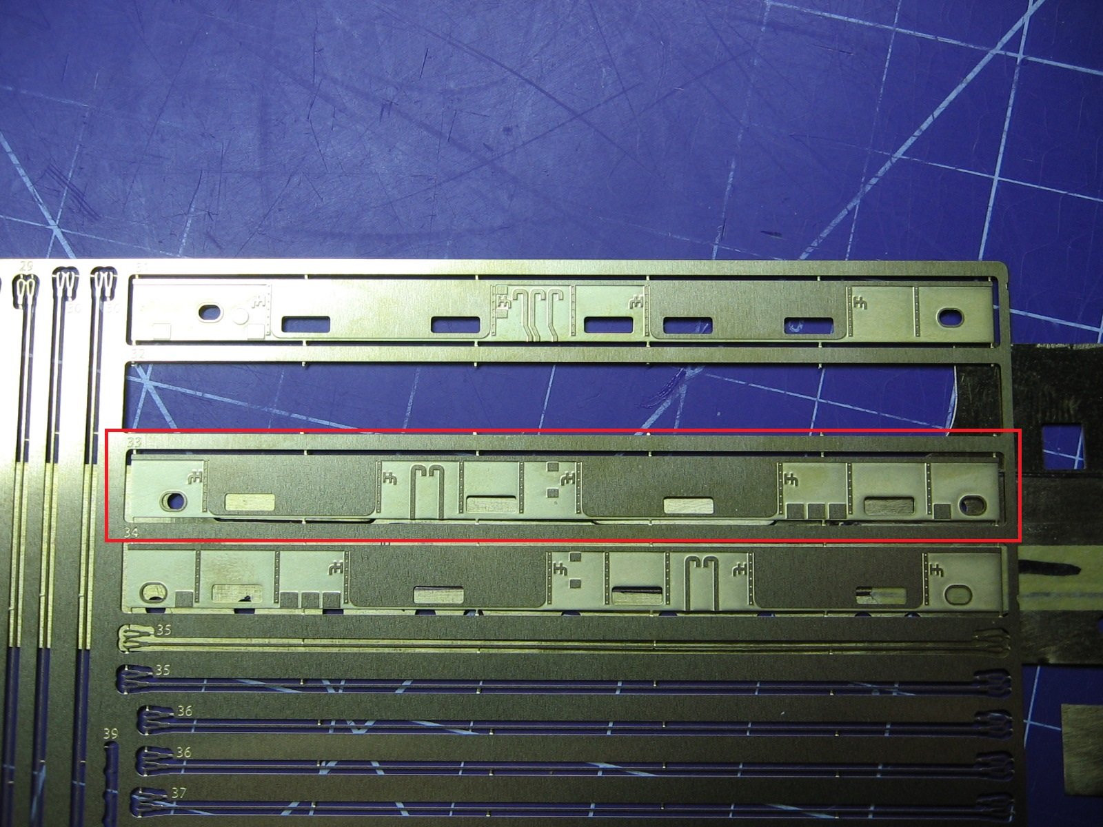
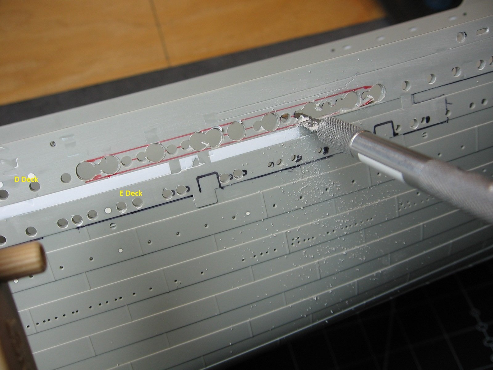
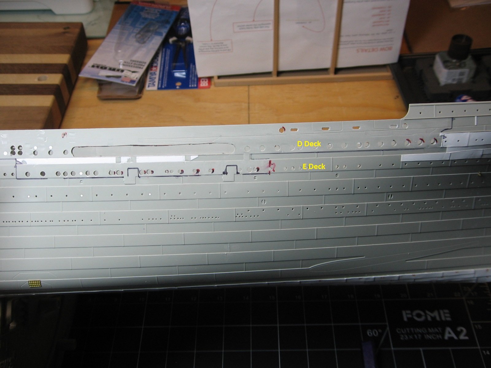
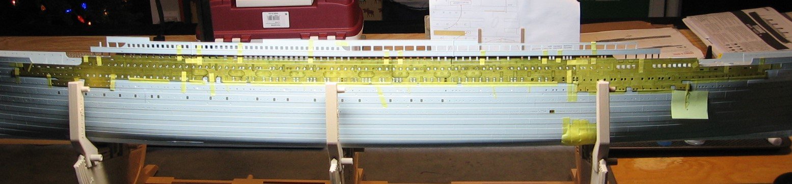
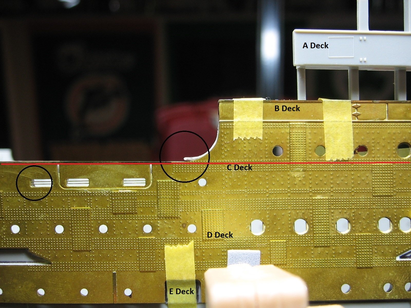
 Thanks for this question, Evan. After much deliberation I have decided not to remove the well deck bulwarks. More on that decision later in this post. Update: After ~6 mark ups and ~7 dry fits (I lost count), and many hours of drilling and filing in between, the Port side of the hull is finally prepped for the Mini Brass PE. The Starboard side prep should go much faster, given that I now know what I'm doing as well as not having to prep parts N1 and P1, as I'm going with the pending AM support frame. The mark ups currently showing in the following pictures are for relocating the incorrect portholes on the Port side. Contrary to what I side about those earlier in this build log, I've decided to do them. They will be next, before proceeding with the Starboard side prep. Some words on my experience with this AM kit (Mini Brass Hull Profiles) so far: I can't explain why this porthole, near the aft well deck, is partially covered. This porthole is, unfortunately, not one of the portholes on the "remove" (fill) list. It did exist in this location. I have since filled this porthole. Not sure what else to do, short of trimming the PE here and adding a styrene strip to replace the plate seam doubling plate, which would be lost by doing so. Any opinions on this aspect would be greatly appreciated. Further to this, and a potential cause: The instructions for this AM kit provide guidance on the placement of the PE in a vertical plane. "The PE should be lined up with the bottom of the outer strake of D-deck (marked with a red line in the graphic below). Dry fit the pieces to to get a clear idea where each piece needs to go." This guidance is very much appreciated. Having said that, the fitting of the PE on the vertical plane becomes somewhat obvious during the first dry fit. What is far less obvious is the placement of the PE on the longitudinal plane. However, there is zero mention provided regarding where to place the first piece with regard to longitudinal placement. No datum. No benchmark. Guidance in the instructions on that would go a long way. With the first dry fit, I started forward and lined up the forward well deck wash ports of the PE's Section A with the wash ports on the Trumpeter hull because, well, they lined up. This was my benchmark. Many of the portholes of the first section lined up as well, with this benchmark. In doing this, I discovered some of this coping strip (within the red circle) required trimming. Part of this coping strip, aft, required trimming as well. Unfortunately, I had not noticed the partially covered porthole until much later, after I had already done significant surgery to the hull. Shifting everything 1mm forward was not an option, in my mind. That would cause more surgery required, not to mention who knows what all else. Again, I'm considering trimming the PE to expose the porthole fully. The Well Deck Bulwarks: As mentioned at the beginning of this post, I have decided to not cut these away. Having seen Evan's work on his Titanic in this regard, I was very much interested in removing these bulwarks as well. The only difference for me would be replacing the curvature of the bulwark forward (forward well deck) and bulwark curvature aft (aft well deck) with styrene, as the PE would take care of the rest. I figured I could follow and replicate Evan's lead on this and was 90% committed to take the plunge. Only one more question remained. Would the KA and/or Pontos PE I have, representing the inboard side of these bulwarks, line up with the Mini Brass PE? KA PE, forward well deck, Port. KA PE, aft well deck, Port. Unfortunately, they do not line up. Pontos does not line up either. Rats. As far as I know, there is no other AM PE available for the inboard side of these bulwarks. These are the only two options. Having said that, I want to use the KA PE in these places and I figure the thickness of the Trumpeter hull will provide enough separation from the Mini Brass PE to render the misalignment a non-issue. Hence, my decision to leave the bulwarks intact. Much thanks to Evan, regardless, for putting the thought in my head. Not much else to say at this point. As mentioned, will do the porthole relocations next and then on to prepping the starboard side for the Mini Brass PE. Thanks for looking. Cheers, Mark

-Copy.thumb.JPG.9e9ef7f2edf3ef3176c4c571c5fb6905.JPG)
-Copy.thumb.JPG.45820efea912ef5b10025b1d11df4fcb.JPG)

-
richardhd reacted to a post in a topic:
RMS Titanic by MisterMeester - Trumpeter - 1/200 - PLASTIC
-
yvesvidal reacted to a post in a topic:
RMS Titanic by MisterMeester - Trumpeter - 1/200 - PLASTIC
-
GrandpaPhil reacted to a post in a topic:
RMS Titanic by MisterMeester - Trumpeter - 1/200 - PLASTIC
-
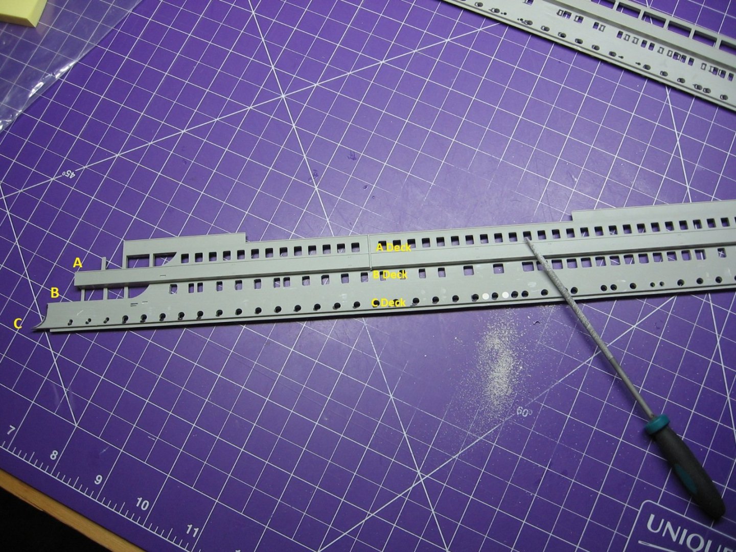
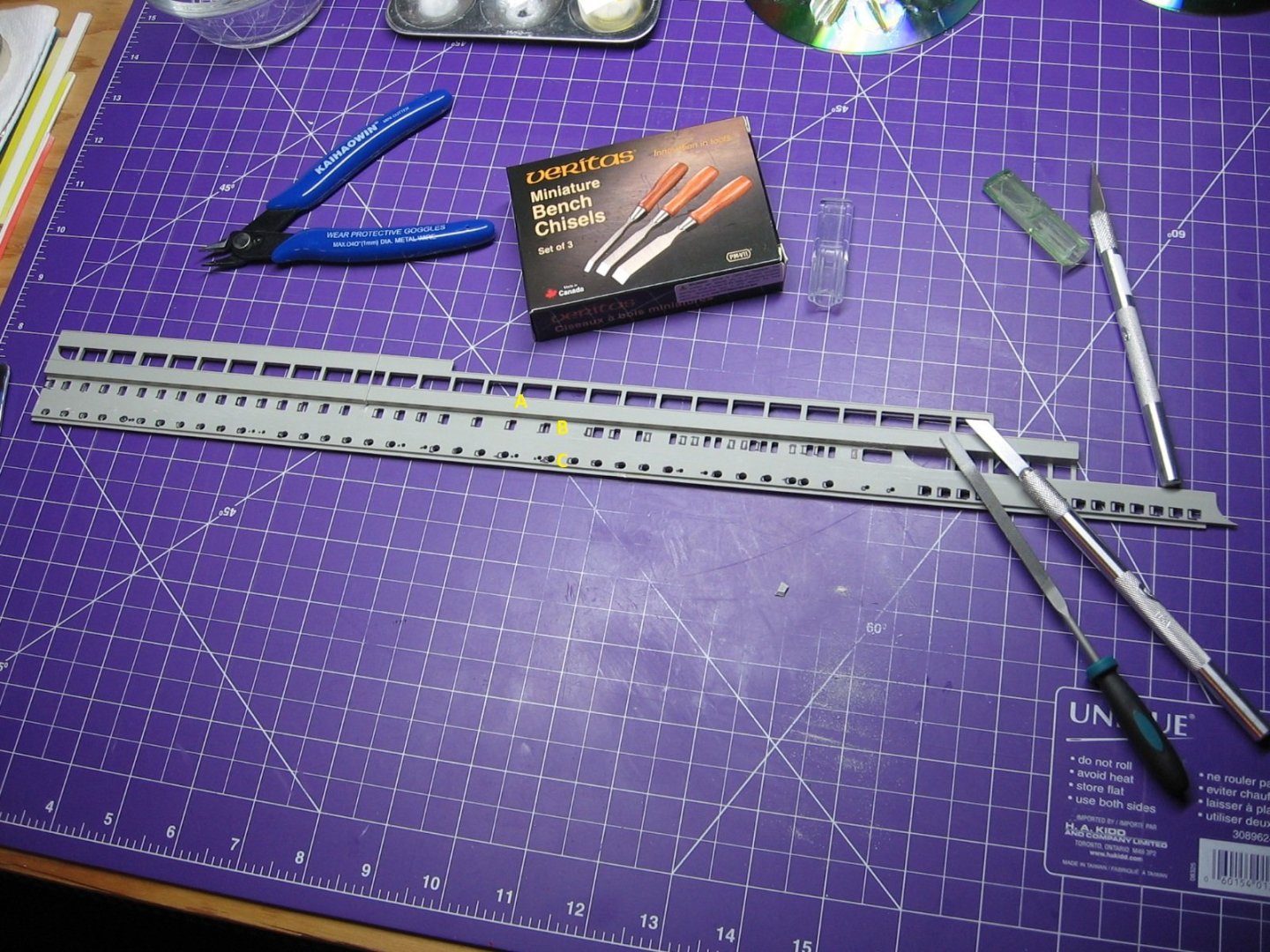
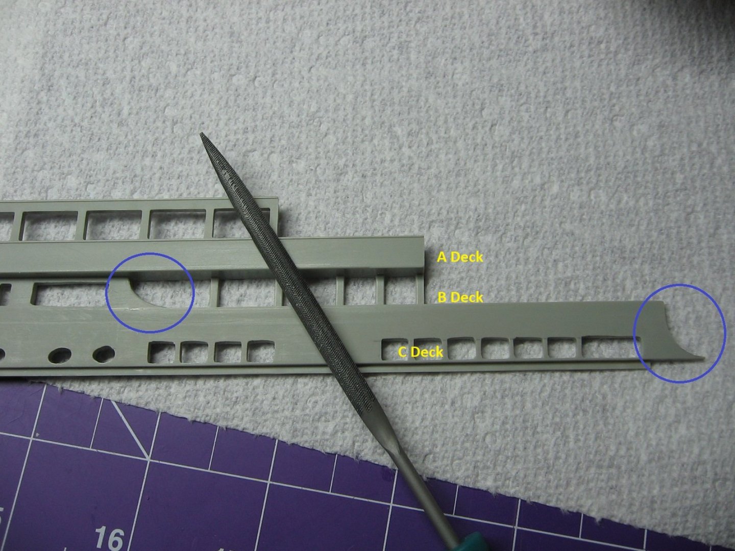
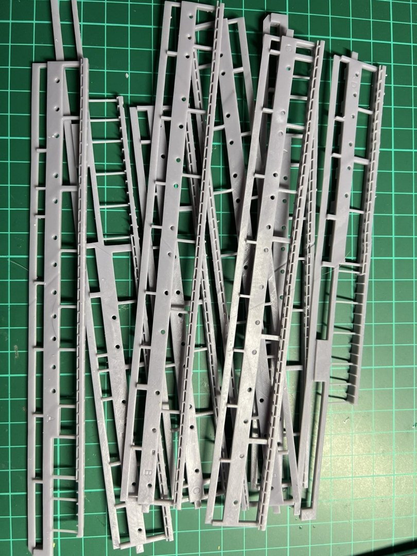
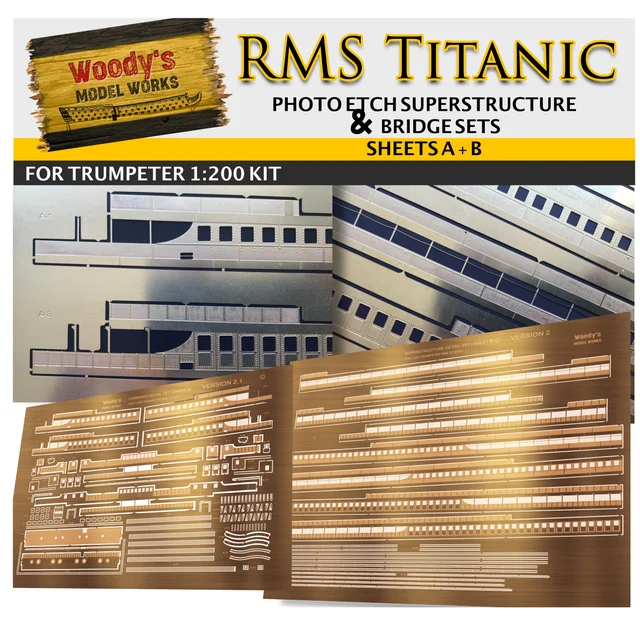
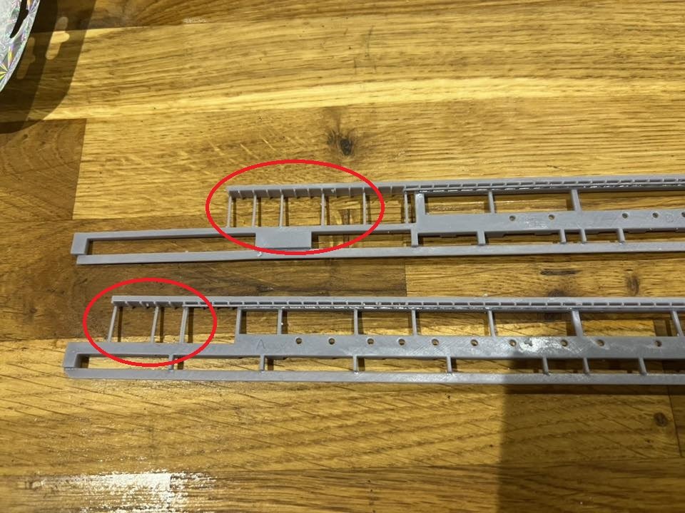
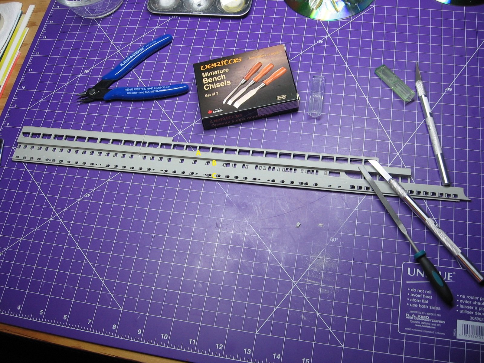
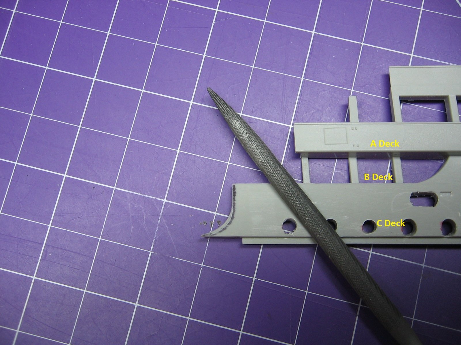
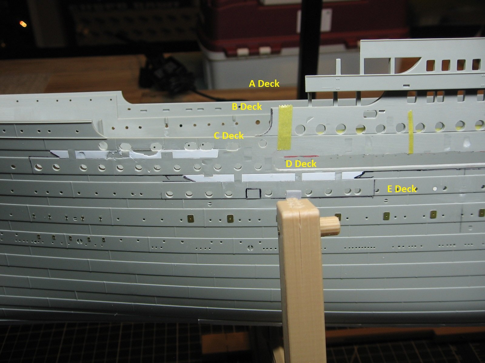
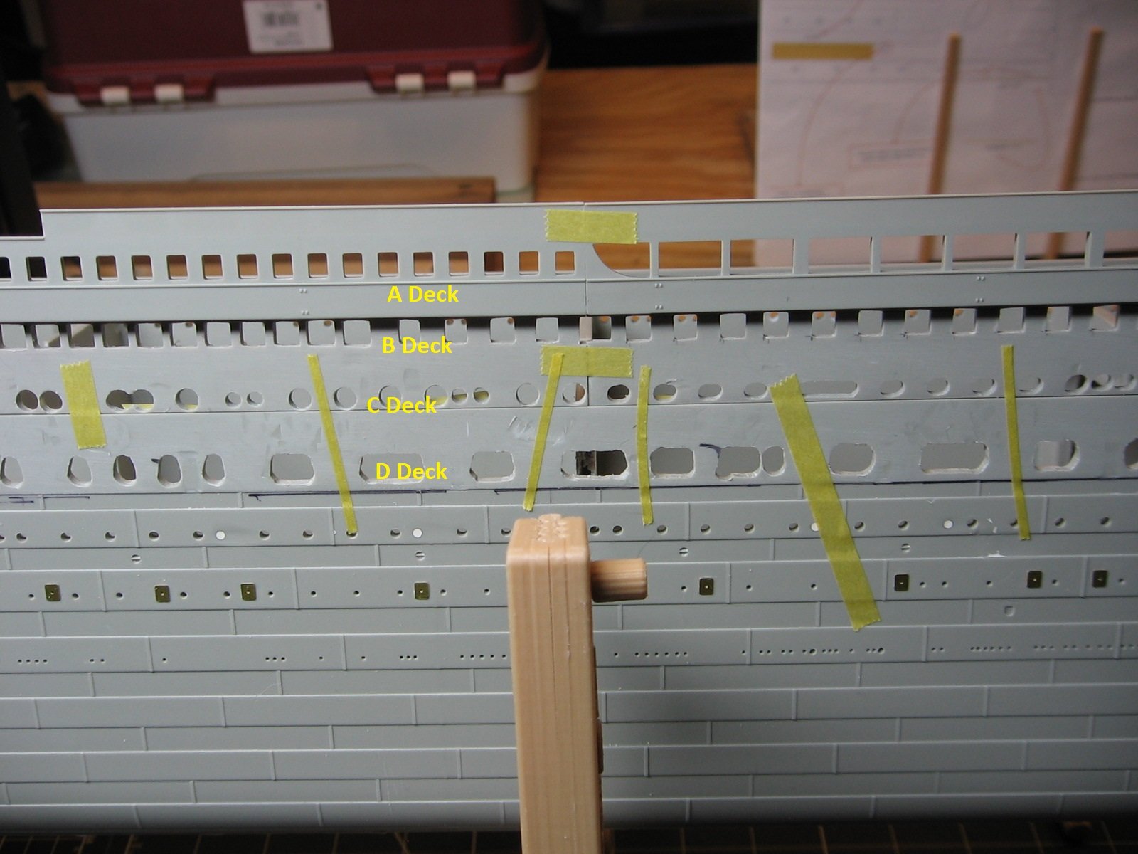
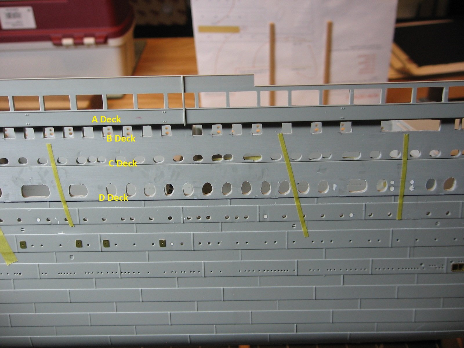
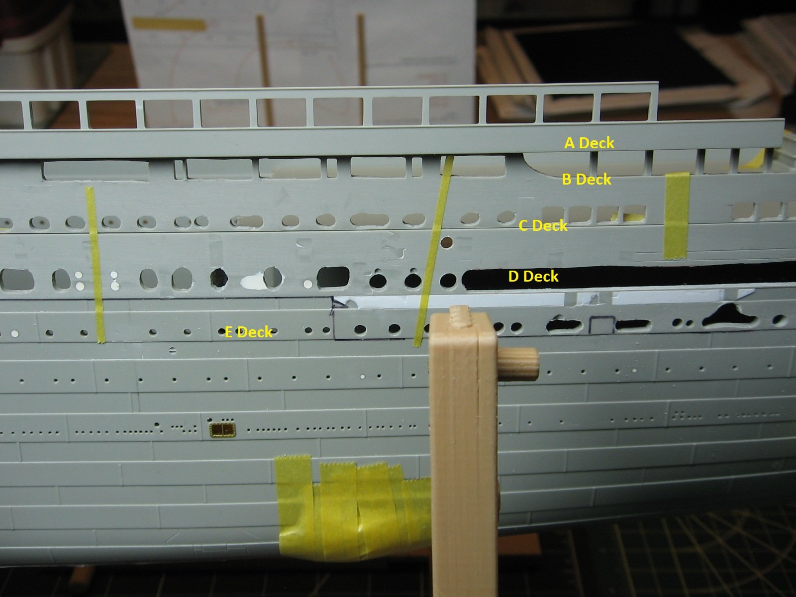
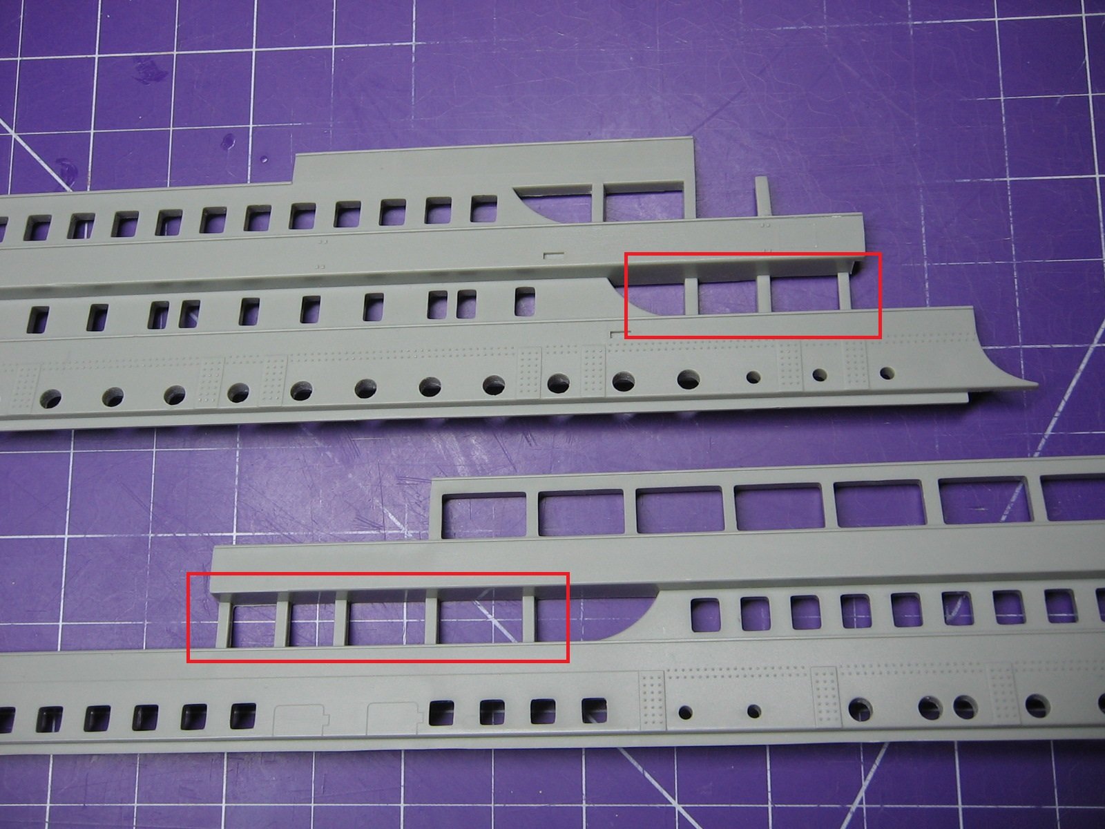
Not sure where to start. Hoping I can convey this update coherently. It's been awhile. On the one hand, I feel an update is not warranted as I have yet to complete prepping the hull, and P & N parts, on just the port side alone, let alone both port AND starboard. On the other hand, this model is very fluid, with its share of plot twists and various options, and shifting decisions as a result. In other words, this update is warranted for the reason that I've changed my mind on a couple of things. Lots of pictures coming that probably don't say much (sorry about that), but if they help another modeler considering the aftermarket kits I speak of here then it's a win. Initially, I did a dry fit of the PE for the purpose of doing a markup and get an idea of where to cut. These photos show work done on the forward portion of the hull. The large lengthy gap was created to accommodate Backplate DP of Part A from Sheet 1. I saw this done on another modeler's build photos. And similarly further aft, big gap to accommodate Backplate DPA of Part D, from Sheet 3. For the other portholes, windows, etc. I worked on each individually, mostly filing by hand. The next four photos show parts N and P. Note that the bulwark curvatures require modifying to match the PE curvatures. In this photo I've indicated the two aft curvatures, that also required modifying. I neglected to take a photo of this prior to filing them down. A second dry fitting revealed I had not removed enough plastic on many portholes, windows and other openings (ie: washports). After more mark ups, I decided to drill some of these out wider, and hopefully save some laborious filing time. The intent was to keep the removal of plastic to a minimum to preserve structural integrity of the kit pieces. More photos showing the current results. Onto the third dry fitting. These next four photos are some examples of even more plastic that is still showing. Ugh. There's got to be a better way. Well, turns out there is. A support frame that takes the place on parts N and P. I was aware of this kit, but could not find where to source it. I don't know the history of it, but for whatever reason(s) it became unavailable, as far as I could tell, somewhere along the line. Until just recently. Woody's Model Works (aka Maritime Models), in the UK, is now printing it. Here's where it gets a bit complicated. The Mini Brass Hull Profiles PE only covers B Deck, C Deck, D Deck, and some of E Deck. Wait what?, what about A Deck? Woody's to the rescue again. Since I had relative success with putting together the Mini Brass PE, I have had my eye on this PE as well anyway. BTW, "Sheets A+B" is not to be confused with Decks A & B. These two sheets (A+B) are for A Deck (as well as PE for other aspects of the ship). One question I had for Neil (Neil Woods of Woody's) was.... what about these B Deck stanchions? Does the support frame have those? Because..... ...... these stanchions are not represented in the Mini Brass Hull Profiles PE. Neil's answer: They are included. So. Phew! To summarize. - The support frame is for BOTH PE kits. The Mini Brass Hull Profiles kit AND the Woody's Superstructure & Bridge Sets kit. - The Mini Brass Hull Profiles kit does not cover A deck. Only Decks B, C, D and E. - Woody's Superstructure & Bridge Sets kit covers A Deck. - Woody's does not make a PE set that covers B - E Decks. Again, I don't know the history, but I surmise that all of these kits were made by one source at one time, and I also believe that for whatever reason(s) that outfit went out of business and the said kits were taken up by others, but not collectively. Again, I don't know. Just speculating. It should also be mentioned that the support frame is not necessary for the A Deck PE. Kit parts N and P can be modified for that. There are two cuts required. But I would still be faced with modifying all the rest of N and P for the Mini Brass kit. The benefit of the support frame is a huge time saver, not to mention much easier to work with. Needless to say, I have ordered the support frame and the Superstructure & Bridge Sets kit from Woody's. Delivery is 4-8 weeks away. In the meantime, I'll continue on with the needed modifications of the hull (primarily D Deck and E Deck openings) for the Mini Brass PE. Sorry for the long winded update. Thanks for looking. Cheers, Mark


-
Ahoy, Richard! Frustrating indeed. Update follows. Cheers, Mark
-
MisterMeester reacted to a post in a topic:
RMS Titanic by MisterMeester - Trumpeter - 1/200 - PLASTIC
-
king derelict reacted to a post in a topic:
RMS Titanic by MisterMeester - Trumpeter - 1/200 - PLASTIC
-
richardhd reacted to a post in a topic:
RMS Titanic by MisterMeester - Trumpeter - 1/200 - PLASTIC
-
yvesvidal reacted to a post in a topic:
RMS Titanic by MisterMeester - Trumpeter - 1/200 - PLASTIC
-
GrandpaPhil reacted to a post in a topic:
RMS Titanic by MisterMeester - Trumpeter - 1/200 - PLASTIC
-
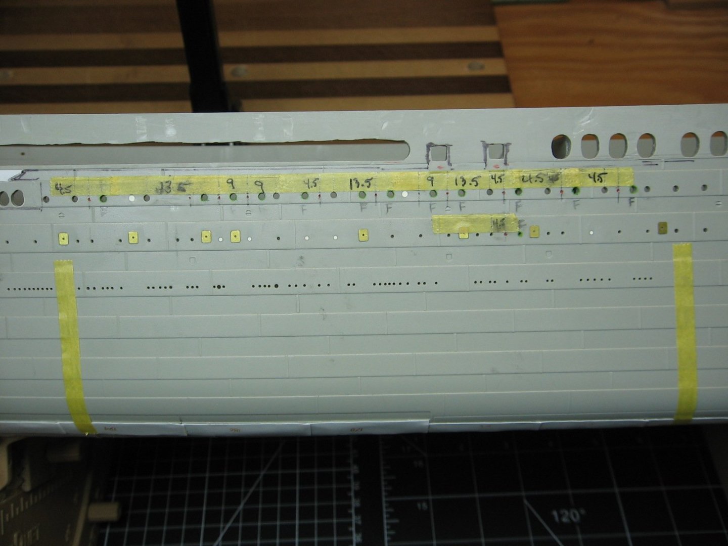
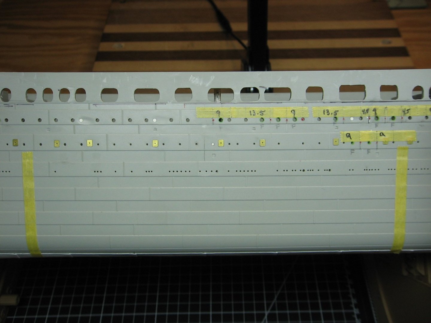
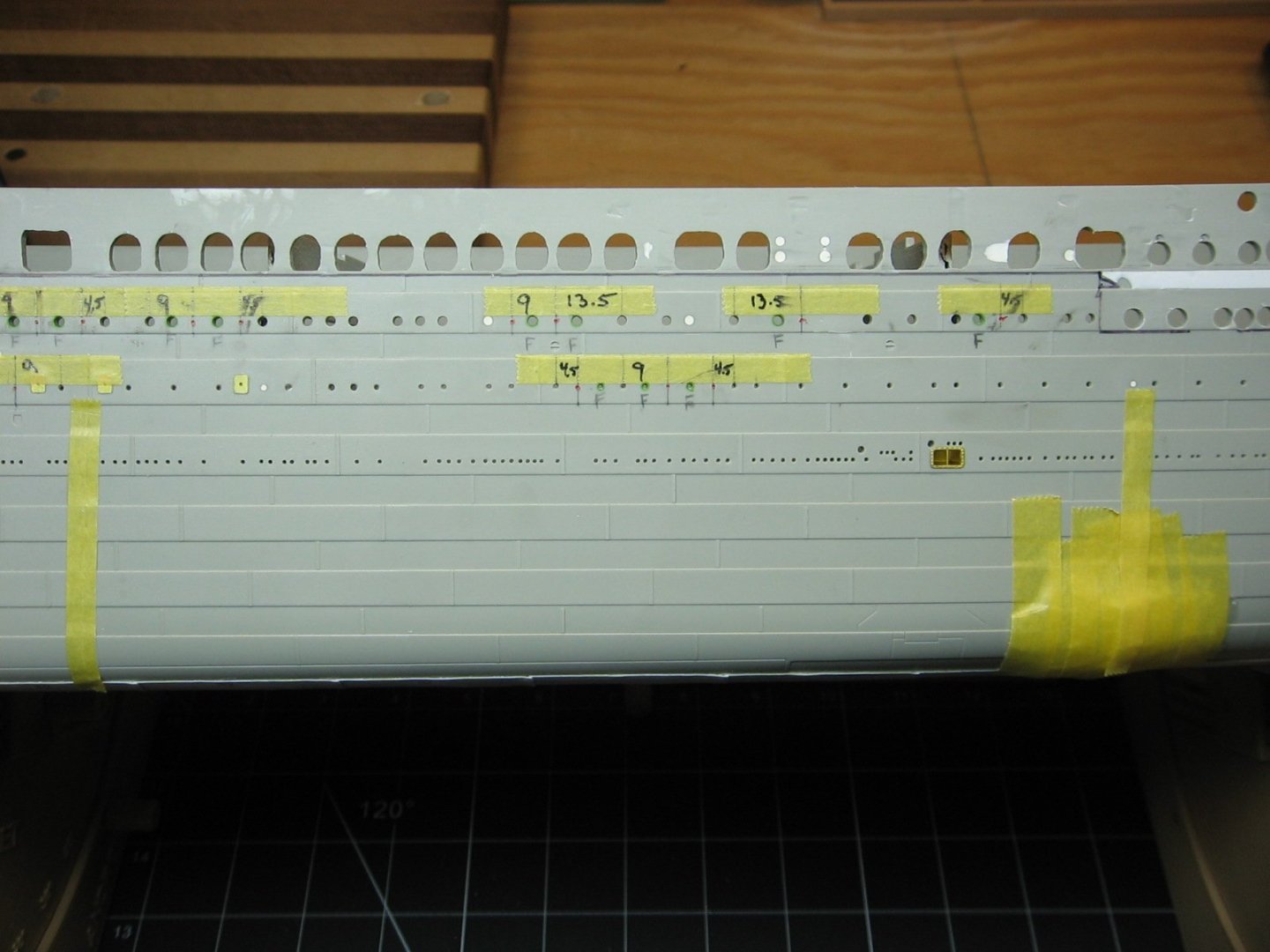
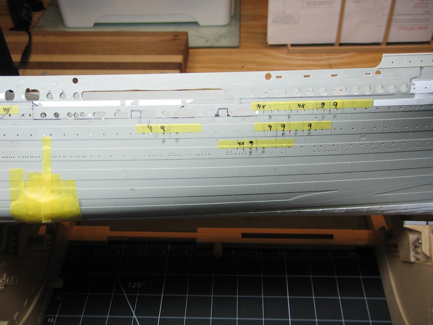
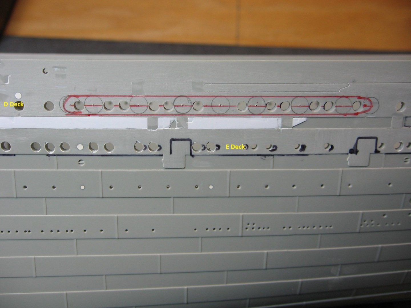
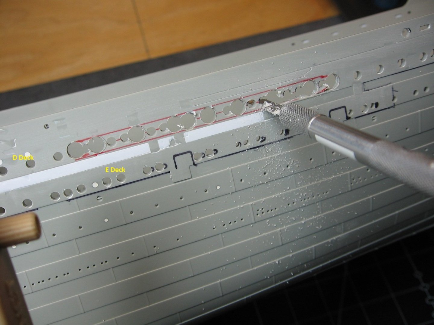
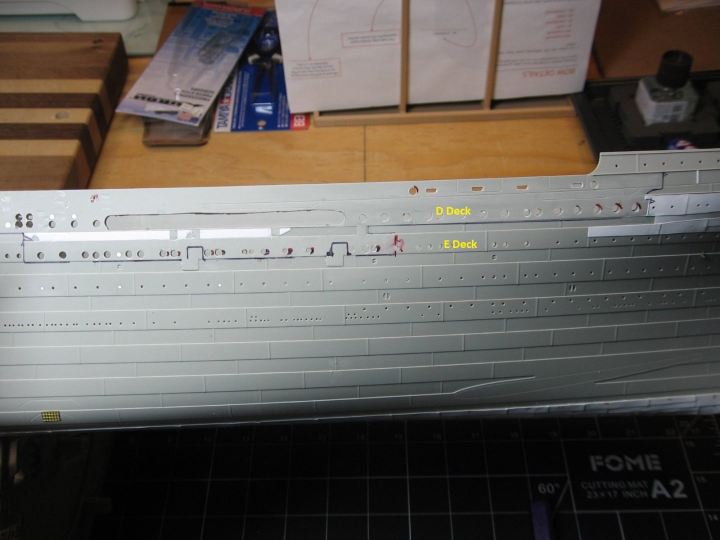
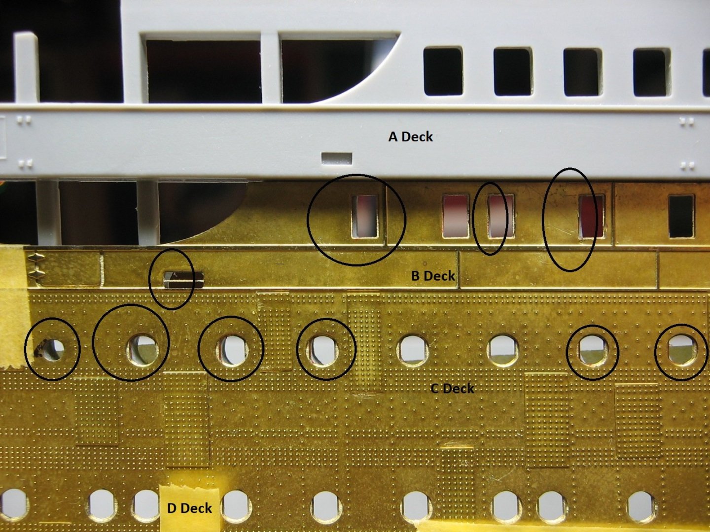
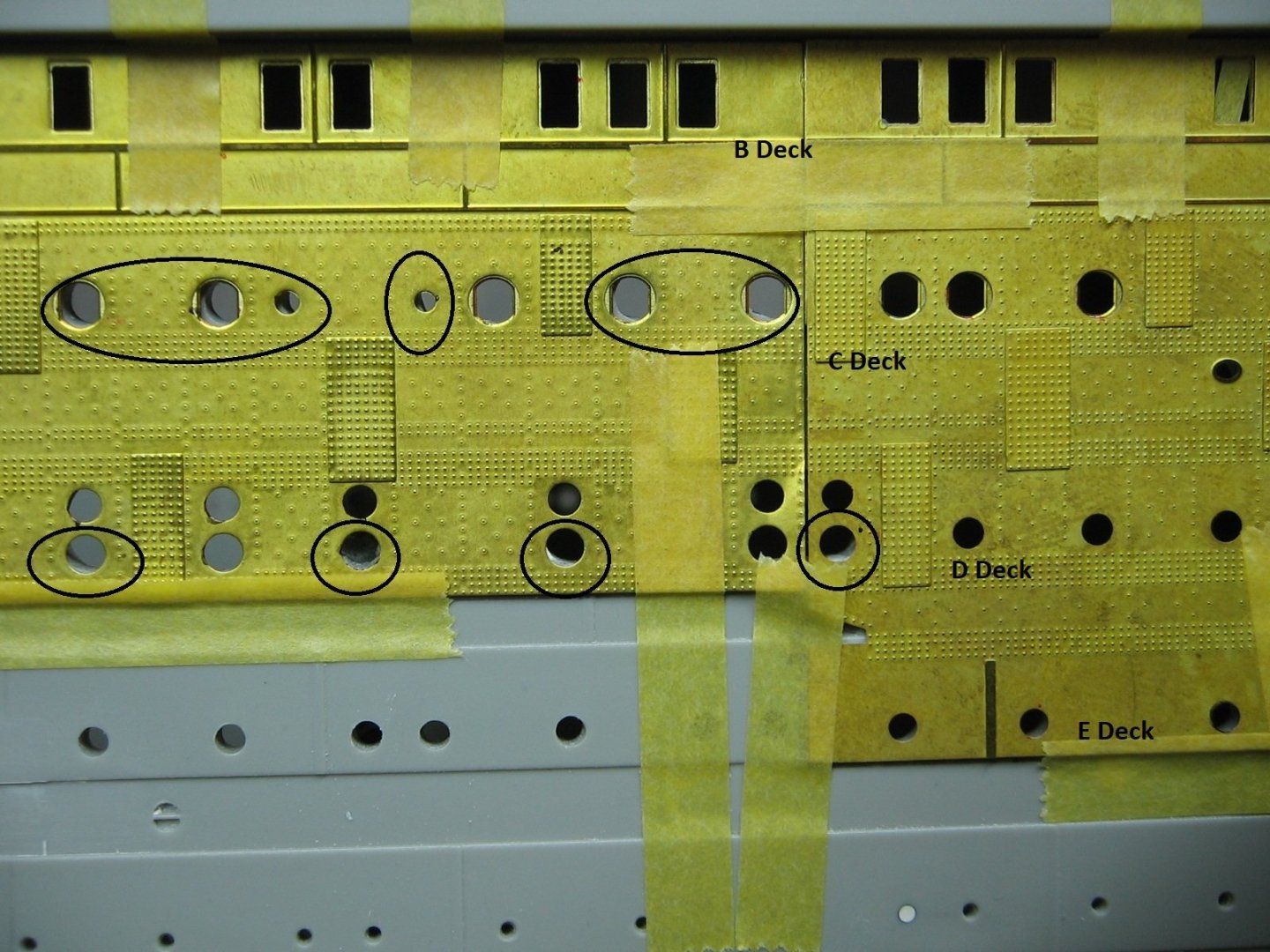
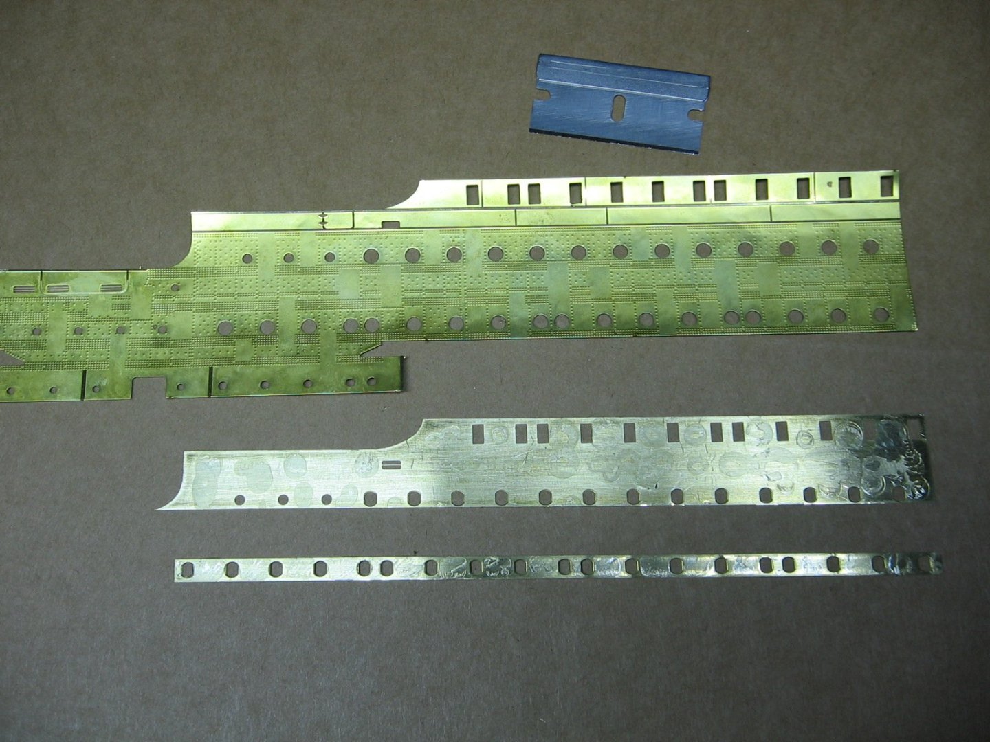
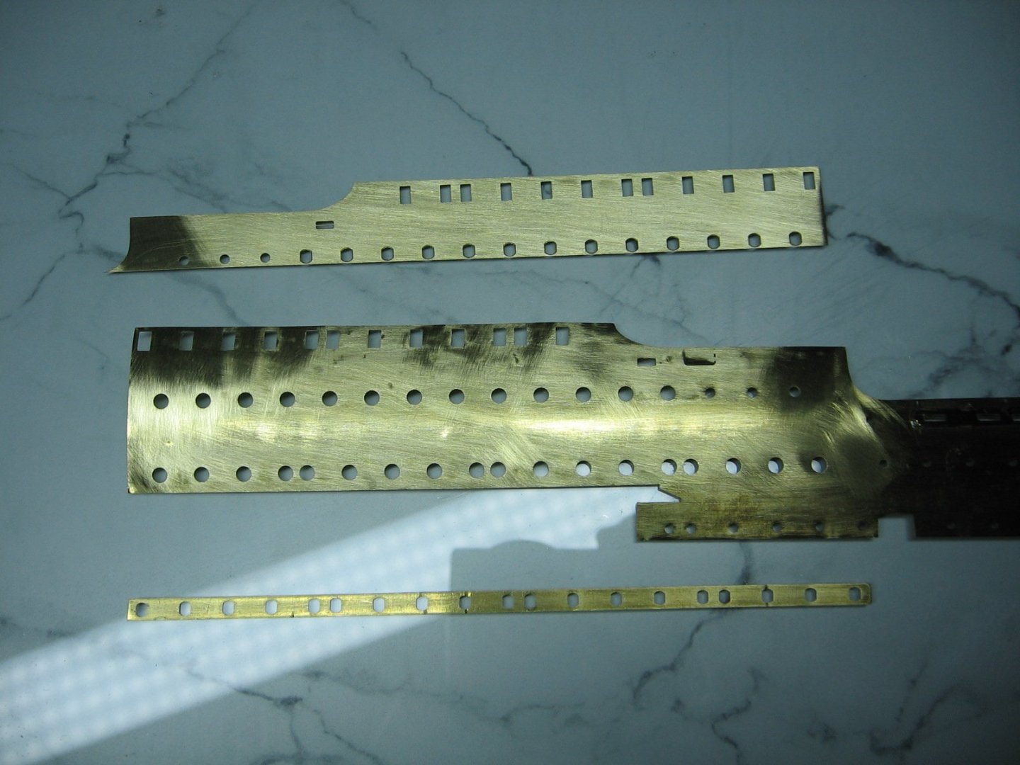
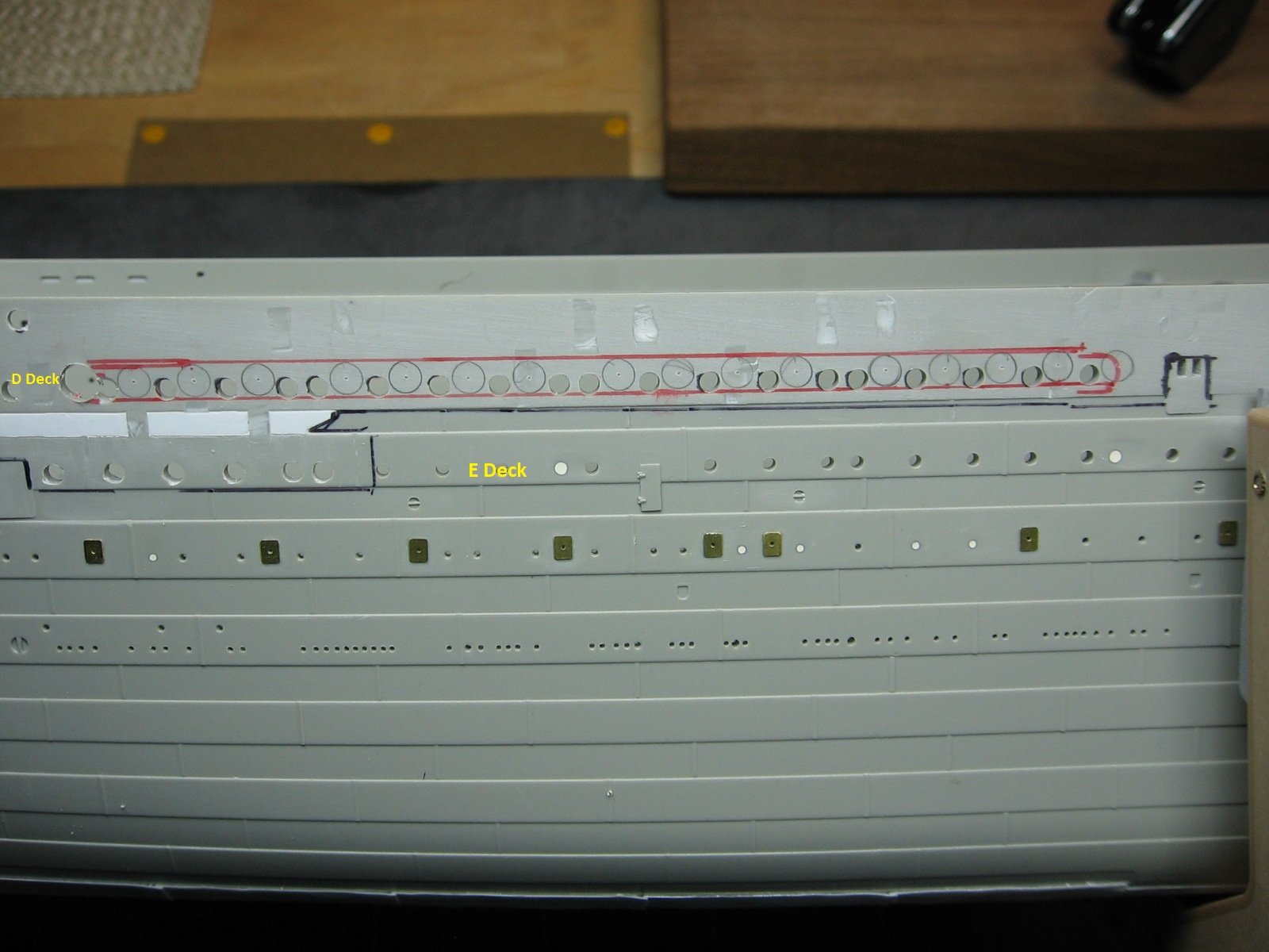
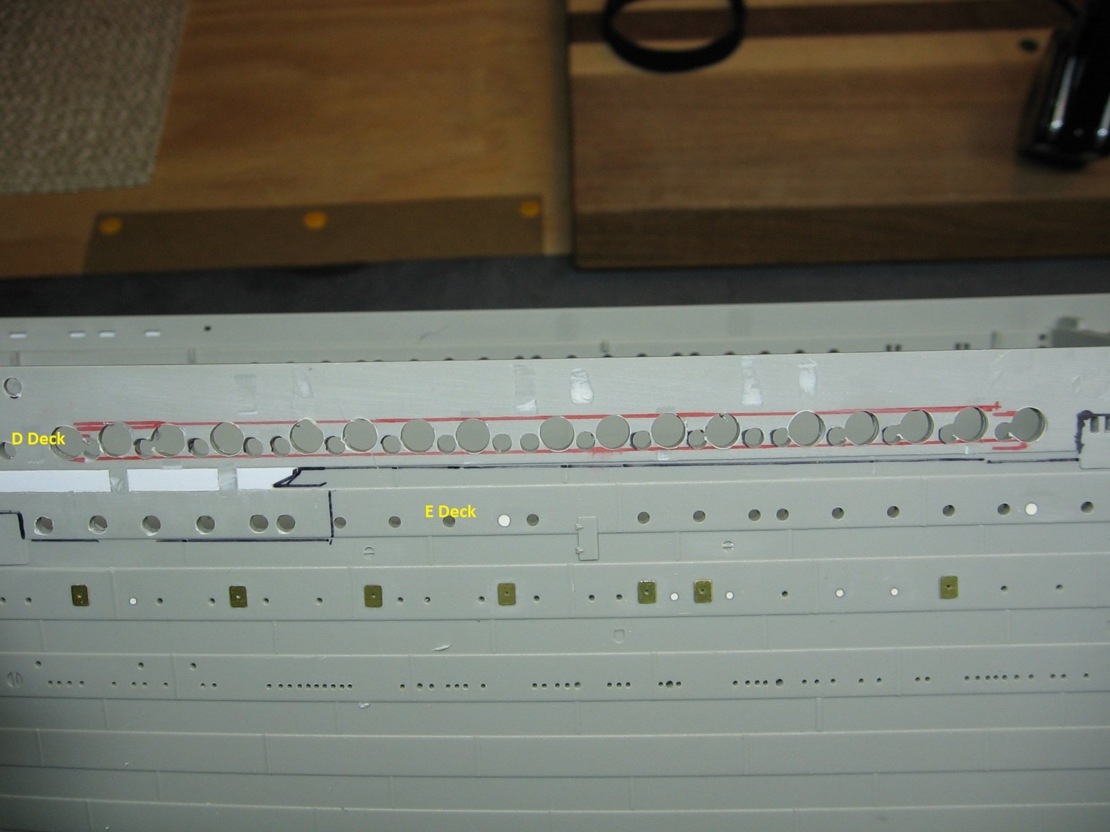
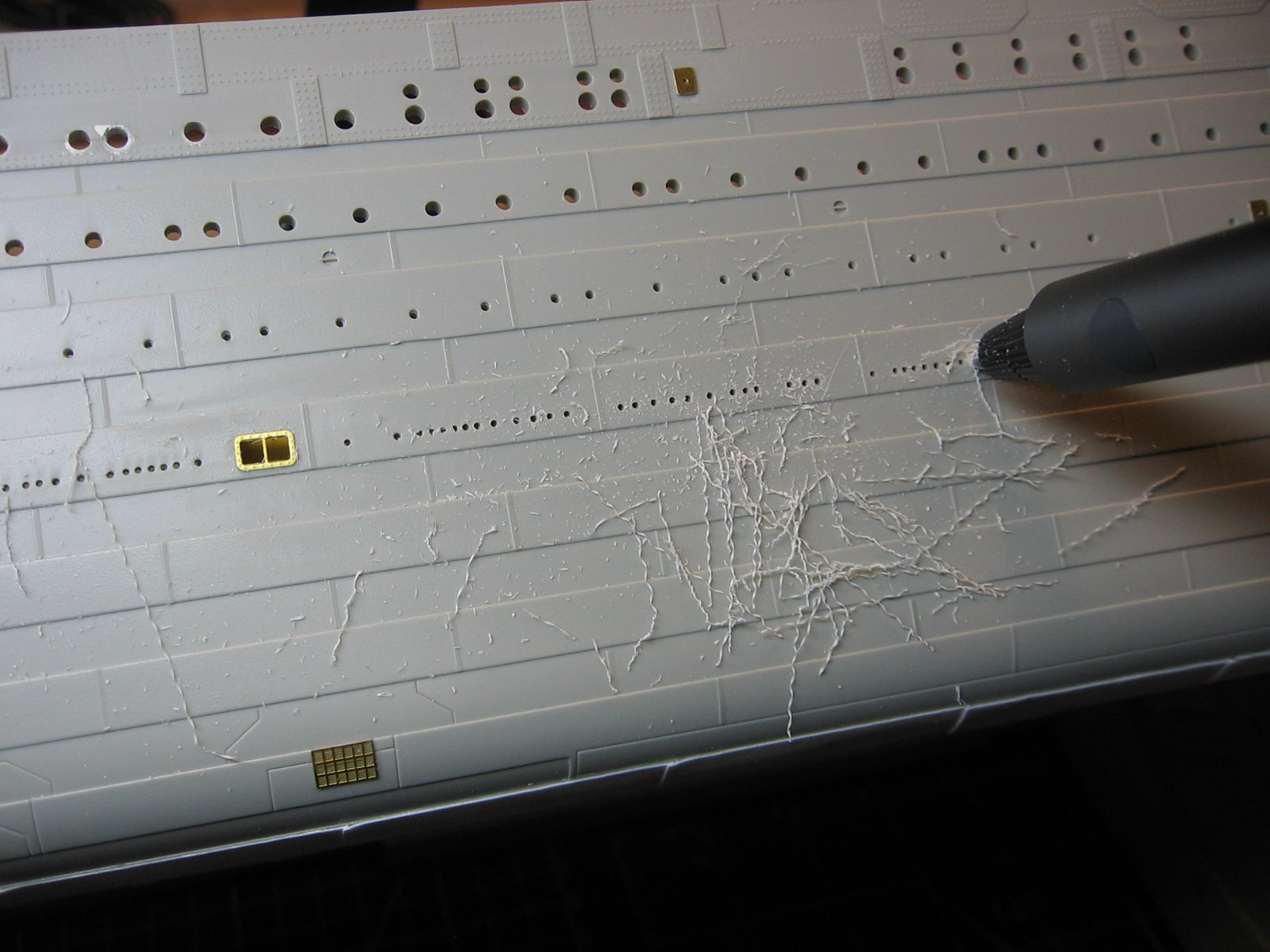
Changed my mind on getting to the propeller shaft wings and bilge keels next. Will get to those later. I need to address something else so I can get back to content sleeps at night. I did a dry fit of the Mini Brass Hull Profiles PE kit, port side. Ugh. As one can see by the photos, alignment is perfect in some parts (circled in green), but grossly not in other spots (circled in red). In hindsight I suppose more research on others experiences with this aftermarket kit would have been prudent. Apparently, turns out the kit hull has even more inaccuracies and, in this regard, the Mini Brass PE is correct. Who knew? If I had known that, I likely would NOT have purchased the kit. One of the reasons I was sold on it was that I expected no major surgery required. There is no mention of major surgery in the instructions, which I perused online prior to taking the leap. Having said all that, and given the amount of time and money already invested in this PE, I think I can make it work. Unfortunately, I have already drilled out the portholes. Less surgery would be required if they were still intact. First step is to remove the raised detail for a flush surface. Then more dry fitting for a better understanding of where I need to cut. Thanks for looking. Cheers, Mark
.thumb.JPG.62ac01be95eec02816e80ad65b92cdac.JPG)
.thumb.JPG.53f5b524c7f0a5523ef7bce78f1582d6.JPG)
.thumb.JPG.7299744c767a134d24f47b7191d7b168.JPG)
.thumb.JPG.479b4771c69028ad34b7325b71d27357.JPG)
.thumb.JPG.950009c33473a32451d570e1f3f8fc98.JPG)
-
Doubling plates (all 180 of them) attached. Used CA glue for these. Parts A - D now complete. I found Part CU-2 backplate to be the most difficult. Particularly on the Stbd side (circled in red). It popped off under stress from handling. Re-attached with epoxy. Unfortunately I re-attached it without paying attention to alignment. Thus, it is slightly off by about 1-2mm longitudinally. Shouldn't be a big deal and hardly noticeable. Up next, as per instructions, with this PE kit is to prepare the hull. However, before engaging in that surgery, I want to do somewhat of a dry fit first. As well, there are other hull features still to be attached. For attaching the bilge keels and propeller/shaft wings I expect I'm going to want to flip the hull upside down. I'm quite certain that would not be a good idea with this PE in place. Further, kit parts N1 & N2 and P1 & P2 (for A, B, and C decks) come into play with this PE. Having said that, it's time to install the internal frame aftermarket kit. Original plan was to install the frame kit after painting the hull, as it would be much easier to install the porthole "glass" without the frames in place. But that plan was before I decided on this PE kit, and plans change. Glueing one frame at a time. I did not have a bar clamp large enough for this, so went out and bought one. At $18.99 CDN each (on sale, down from $29.99) it made more sense to get just one, instead of four. In the meantime, prior to starting on the internal framing, I was pondering the lowest row of molded indentations on the hull, which represent through hull fittings. Common advice regarding these is to DON'T DRILL THESE OUT(!). But wait.....I'm not lighting my model, and therefore, there would be no light leakage through these if they were drilled. I decided the overall look will be better with them drilled. Left undrilled, some of them will end up painted over with antifouling red. Done. Second frame glued in this morning. Two more to go. Should have that completed within a couple of days. After that will be the bilge keels and propeller/shaft wings. Thanks for looking. Cheers, Mark
.thumb.JPG.1d595170151c569e4a3b9e8984b547b3.JPG)
-
Parts CU1 and CU2. For the Port side, I treated these parts same as the previous back plates. Worked them from the back side. Measured for fit and applied epoxy. Then flipped the sheet over for fine tune positioning. As soon as I flipped the sheet over both pieces fell off. I wasn't able to apply enough glue for the parts to remain attached during the flip. Bit of a gong show, from that point, but I managed to position the parts while working them from the topside and using CA glue in conjunction with capillary action. Different approach for the Starboard side, which was way easier. Worked them from the topside from the get go and simply positioned the pieces dry and then taped them in place, followed by applying CA glue at each ends, allowing capillary action to do it's thing. Then, once secure, flipped the sheet over and applied more CA from the backside. On to the Doubling Plates... Thanks for looking. Cheers, Mark
.thumb.JPG.13a6caac30bcb1954a29266d738060ae.JPG)
.thumb.JPG.20805622e536c86af95f65113e7d1529.JPG)
.thumb.JPG.5b5765f603f6db20f31cf0d7166d9c50.JPG)
-
MisterMeester reacted to a post in a topic:
TITANIC by Force9 – Trumpeter - 1/200 - PLASTIC - White Star Liner
-
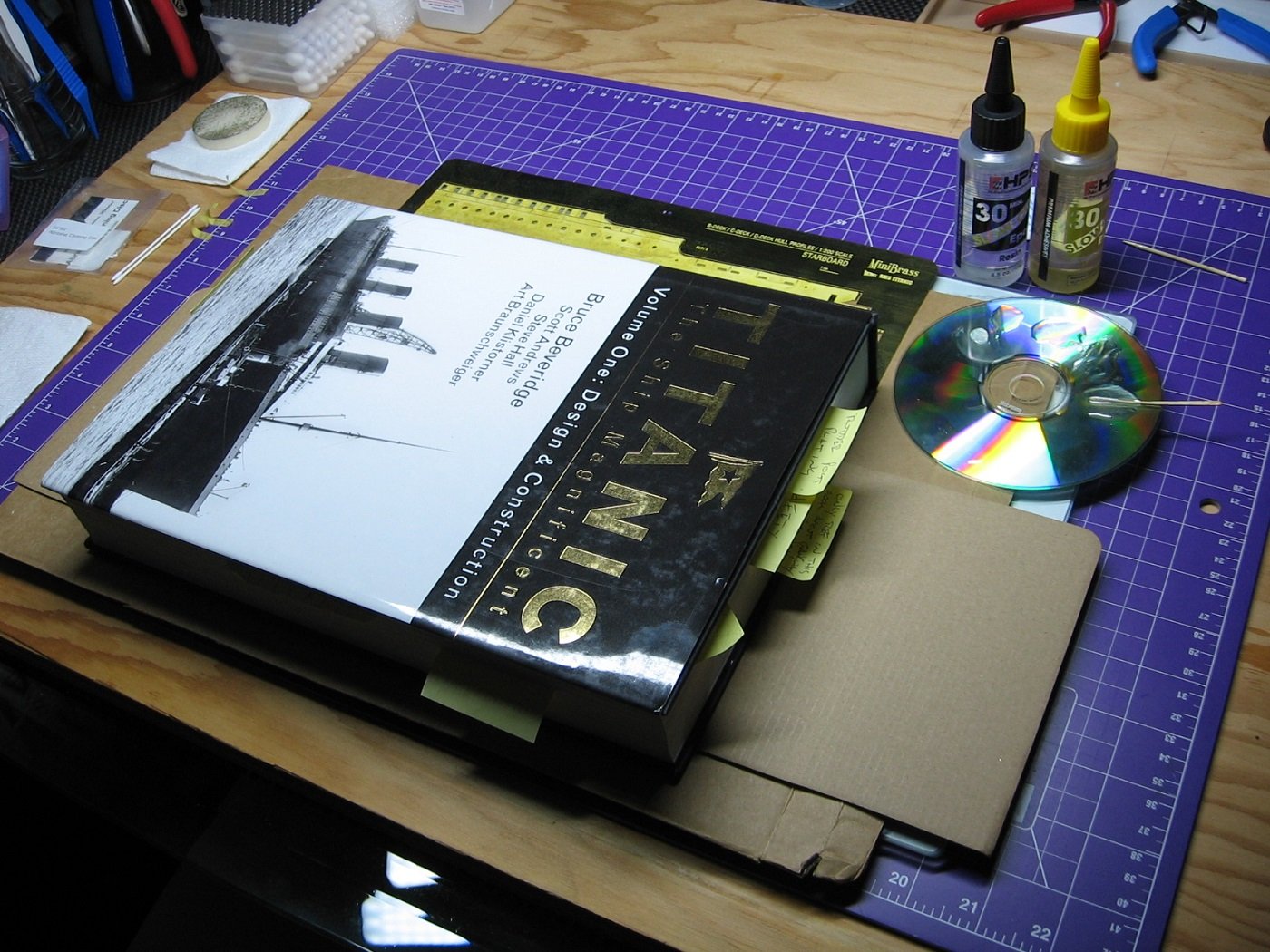
Back Plates of Sheets 1 and 2 done. I've been working on another project, which delayed me for a while, but that's completed now. As well, I found I had to provide weight to the PE to flatten the bends resulting from the shipping damage. Not sure if this would have been required regardless, but me thinks not. At any rate, because of this, I chose to do each of the larger back plates one at a time. I wanted to minimize the possibility of the back plates slipping as much as possible. Thus, this slowed the process down. I chose a BIG HEAVY book for the weight. Further, I switched to a slower curing epoxy. Working out well. On to Sheet #3, and more Back Plates. Four back plates for each side (Port and Starboard) on this sheet. I'm hoping to get all eight done in two applications. We'll see. Thanks for looking. Cheers, Mark
.thumb.JPG.cc83a03b9f3f58da181b95306c98e955.JPG)
.thumb.JPG.996ef9d15fc6fd7cf3a94c6c23aacf57.JPG)
-
MisterMeester reacted to a post in a topic:
RMS Titanic by MisterMeester - Trumpeter - 1/200 - PLASTIC
-
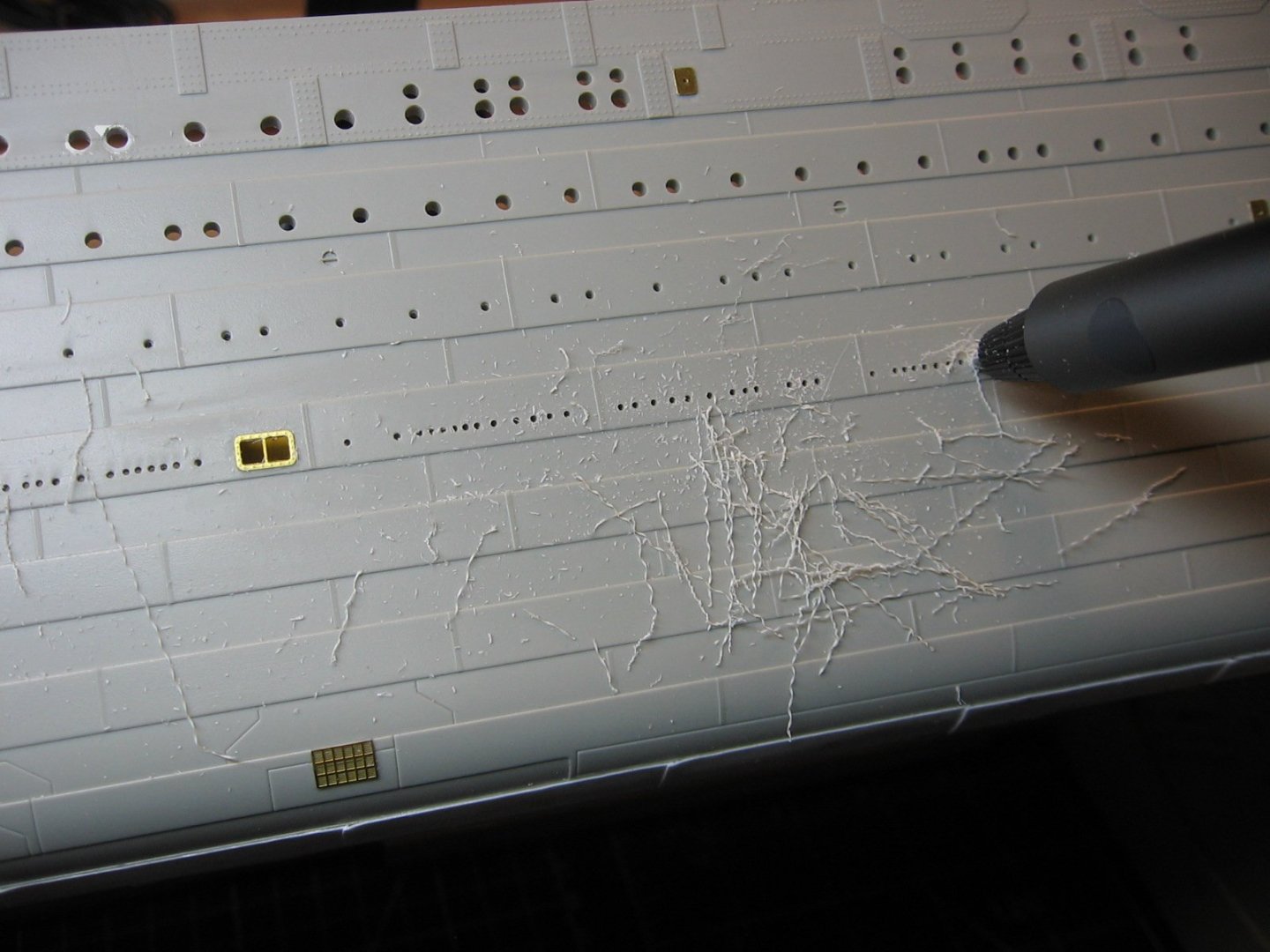
Hello Evan! Thank you for your post. Honestly, removing the well deck bulwarks had never entered my mind. I’ll take a look at that when the time comes, however preliminary thought on that is….leaving the delicate PE without any backing support in that area makes me nervous. I neglected to mention….I found working on the hull, prior to acquiring and employing the cradle I’m using for her, to be awkward and cumbersome. Prior to the cradle, I managed to inadvertently erode away a fair amount of the rivet detail. The main reason I got this MiniBrass kit was to rectify the lost rivet detail. My initial plan was to use 3D rivet decals (I even went as far as purchasing some), but decided the PE was the way to go instead. Cheers, Mark
-
Ahoy Harald! Thanks for your post. The E6000 packaging says it's good for metals, so I suppose it would work. I considered it, but for the sole reason that the instructions do not mention it, I decided on epoxy. I'll be touching up the edges with CA. Speaking of glue....the Gorilla two part epoxy I've been using is 5 minute quick setting. I'm finding it to be not very user friendly for the larger back plates. My method of application involves mixing a puddle of the stuff onto an old CD and transferring it to the PE by way of dabbing a round toothpick in it and applying small drops onto the PE. This is somewhat time consuming. Longer than 5 minutes for the larger plates. The epoxy begins to set before I'm done, resulting in it becoming globby and stringy. Bob Smith Industries makes a "Mid-Cure" (15 minute) and "Slow-Cure" (30 minute) epoxy. Segue to the Saskatoon hobby shop you likely visited. Express Hobbies. Couple of blocks North of 33rd St. It's essentially the one and only here. They have both epoxies in stock. I think I'll get the Slow-Cure and give that a go. Back to the hobby shop....I moved here in 2016. Didn't actually step through their door until 2022. Not sure what else might have been here before then. There's one other store here that I've never been to as they are pretty much all about RC. Cheers, Mark
-
MisterMeester reacted to a post in a topic:
RMS Titanic by MisterMeester - Trumpeter - 1/200 - PLASTIC
-
Argh. Didn't take long to have a couple of issues. I take full accountability for my mistakes, but some clearer and more comprehensive instructions would be nice. But that's part of scale model building, isn't it? The first issue. Fitting Back Plate A, for the Port Side of the kit. As one can see of the port holes within the blue oval, I did not get the back plate lined up properly. The way the instructions are written suggests that the back plate can, and ought to, be fitted in place with Plate A upside down. No. This is not the best way. Don't do what I did. Upon gluing Back Plate C to Plate C (haven't done B yet), I found that what's better is to flip it back over to topside up and work the underneath back plate from above, with a scriber tool. The "Utley" aspect of said portholes, as well as the inside portion of the window frames, are visible and the back plate can be manipulated into position this way. The second issue. Completely got the placement of Back Plate DP wrong. The end in the blue circle needs to be at the end of the green circle. I was wondering why there was no port hole in Plate A for this end of the back plate. Further, I trimmed the end as it was slightly covering the adjacent smaller port hole by ~1mm. I had just assumed this was a manufacturing flaw. Nope. Modeler flaw. Having said that, the instructions could be better. I'm a visual guy and a better diagram would have gone a long way. The contrasting color of blue (the back plates) to grey (the fret, etc.) is not very evident in this particular spot. Further, all the port holes of this back plate are indicated in white....except for the one port hole at the left end, where the red arrow points. Yes, turns out it is indicated, but in extremely hard to see, and easy to miss, grey. Just a poor visual representation. Had it been indicated in white, like all the others, it would have been obvious. Great. What to do? Am I going to have to order another sheet and go through another three months of waiting for it to ship? Thankfully, no. I managed to separate the back plates from Plate A with a straight razor. (Gorilla two part epoxy glue used.) And cleaned up with a sanding stick. Ready for attempt #2. I'm happy, and relieved, to announce that attempt #2 was a success. Back Plates A and DP are now glued on Plate A correctly. Thanks for looking. Cheers, Mark
.thumb.JPG.bebf4e4153e41b8dd63ac19b52456a45.JPG)
.thumb.JPG.68b79821c0ccec4513ebe640750f52f9.JPG)
.thumb.JPG.b9b29d749db54a40c0ee05b208a668ea.JPG)
.thumb.JPG.9320eaa5052749f2f68a8dc514963595.JPG)
.thumb.JPG.f8a7a7936b6333f0b48d4990c189738d.JPG)
.thumb.JPG.7ce09ff5e60dbfe3aa4cc86f4cb4c696.JPG)
-
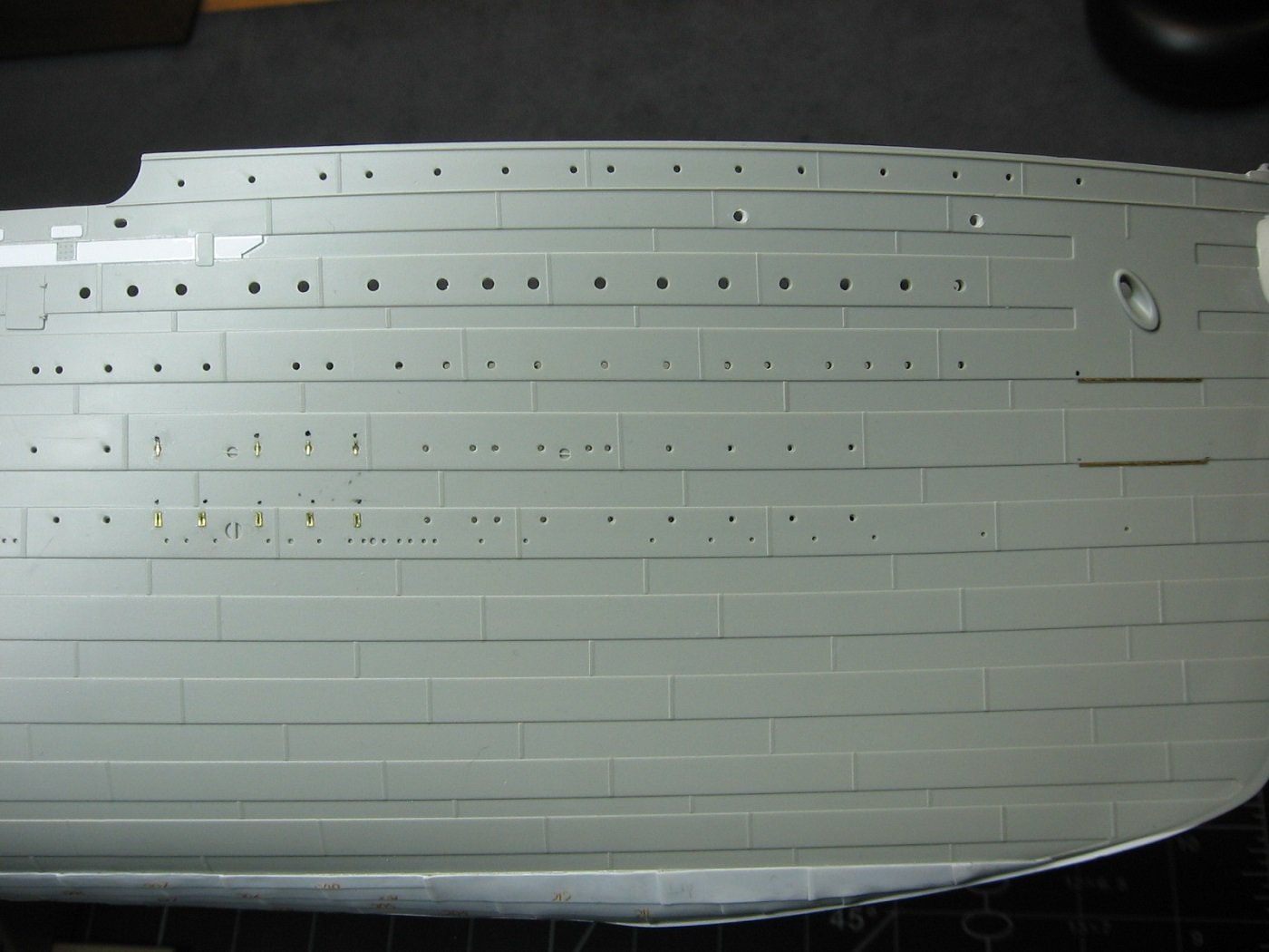
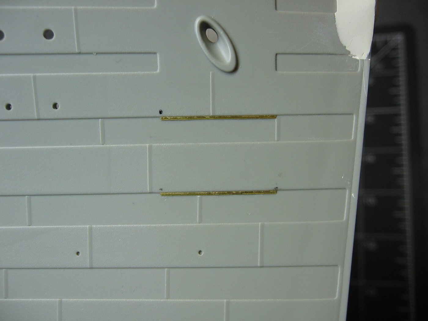
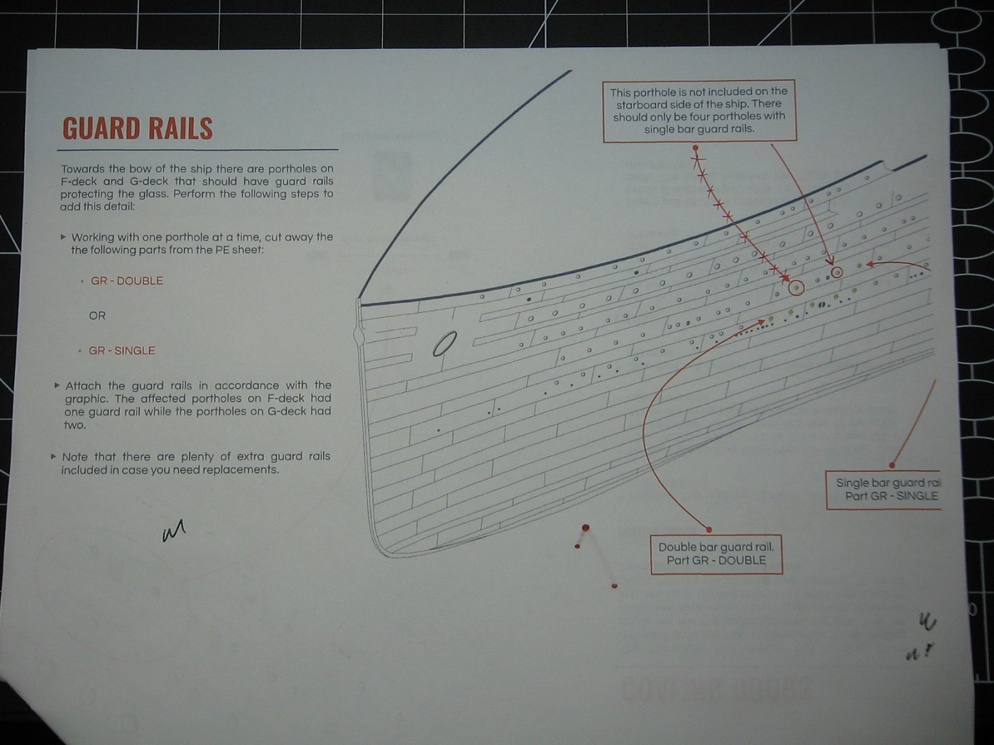
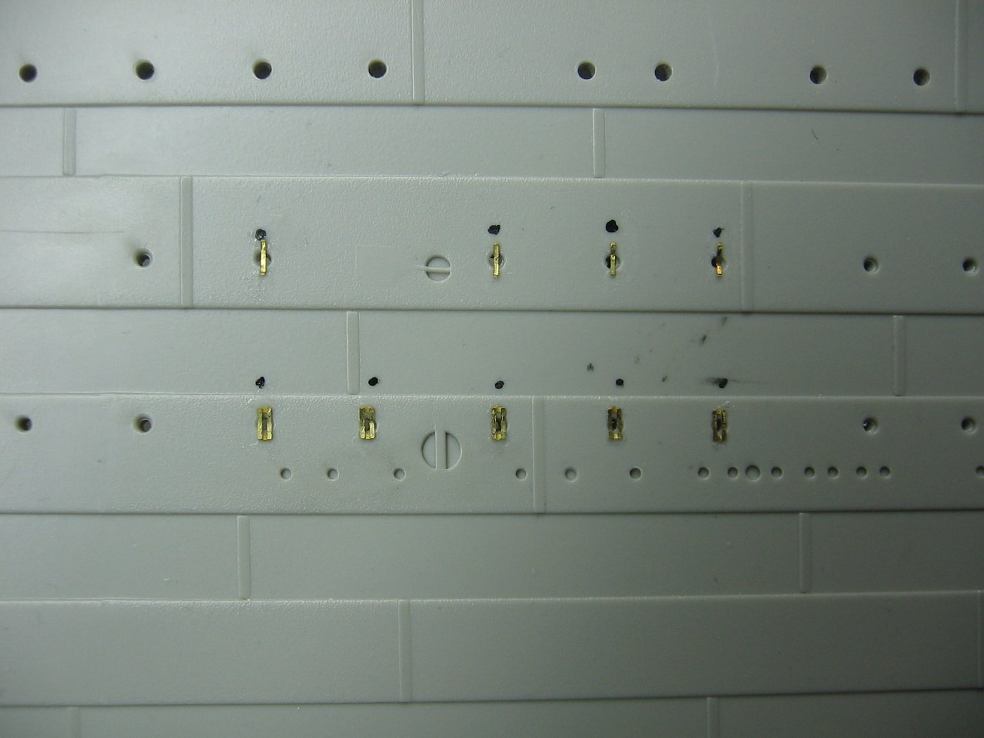
Small update. Got the starboard side anchor guard bars and porthole guard bars glued on a couple weeks ago. In so doing, I discovered a mistake in the instructions. The location of the non-existent porthole indicated (starboard side only) is not where the instructions say, but rather ~20mm further aft. But it's a moot point anyway, as Trumpeter did not even mold this porthole into the hull, and therefore, it's obvious. Golf season is officially over for me (as of 10 days ago). I've been busy with chores around the house, transitioning from summer to winter. Getting back to the bench just now. Next step will be starting work on the MiniBrass Hull Profiles PE set. This set is quite extensive and will transform the hull significantly. The set arrived (last May) damaged. All three sheets bent. I assume this occurred during shipping. I emailed the proprietor advising him of this. I mentioned I thought I could make the damaged product work, but suggested he might want to re-address choice of packaging for future orders. He replied that this is the first time he had a report of damage and assured me that he'd replace any parts that won't work. Fingers crossed. Intro to the instructions... General information page.... First three pages, describing the first steps... Expecting to get started this afternoon. Should be fun. Thanks for looking and cheers, Mark
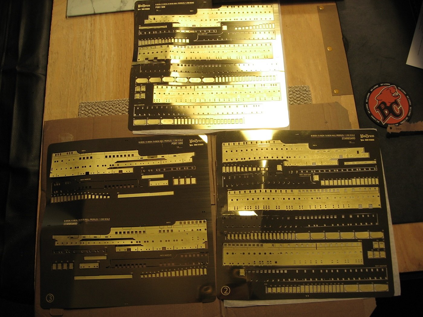
.thumb.JPG.66e9d09aee206efbc441ac4df7790f79.JPG)
.thumb.JPG.ca232c1f861db46727401db7780a4db4.JPG)
.thumb.JPG.686667eb6327f08134c60ec893772300.JPG)
.thumb.JPG.19ce024d84842b3619250fe1a61c2a67.JPG)
.thumb.JPG.5fbce2ae191b12e5d8b74cab7c02aad9.JPG)
-
Ya, they’re quite tiny. And such a huge project overall. I’m figuring two to three more years at least. Probably more. Found your build log and following. Happy modeling and cheers, Mark
-
MisterMeester reacted to a post in a topic:
Titanic 1912 by Winnie - Trumpeter - 1/200 - PLASTIC
-
MisterMeester reacted to a post in a topic:
RMS Titanic by MisterMeester - Trumpeter - 1/200 - PLASTIC
-
MiniBrass Pad Eyes P2, P3, P5, and finally P4 attached. Pad Eyes complete. Not perfect by any means. A few are slightly crooked and there is excess CA glue here and there. Probably goes without saying that the P4 Pad Eyes (the smallest) were the hardest. The white object in the tray on the left in the first pic is a cat whisker. I used that for applying a tiny drop of CA glue to each P4 base before attaching the P4 eye to the base. I forget where I heard about using that as a tool for small amounts of CA as it was quite awhile ago. Perhaps a member of Model Shipwrights of Niagra, but I'm not sure. This is the first time I've employed a cat whisker for that purpose and it worked out quite well. I used a glue looper for all the other gluing. Having said that, one lesson learned with this aspect of my build is I think I underestimate the power of CA glue, and tend to use too much. Looking forward to working with it more. I need to find something to practice on with it. As for fret nubs, I did not bother sanding/filing any nubs off the remaining PE beyond P1. I figured it's so tiny and hardly noticeable that it wasn't worth the bother and risk of losing some of the parts. I considered cleaning them up (fret nubs and excess glue) once attached to the hull, but upon closer inspection with my Vision Aid magnifiers, I'm going to leave well enough alone. Another lesson learned is my eyes aren't what they used to be. Despite using the magnifiers, this PE (especially the P4 eyes) was somewhat difficult to see and work with, but I managed. Hoping I will never have to work with such small PE ever again. I suppose now, the hardest trick of all will be making sure they stay intact. (Read: not get careless and bump them off). One final thought on the Pad Eyes regarding mention of mine upthread of the hole of the eyes getting CA glue in them. How did that happen? Well, in working with the subsequent eyes, it became apparent. It is quite difficult to attach an eye to a base while maintaining a vertical aspect of the eye. Often they wanted to just flop on their side once they came into contact with the drop of glue. Hence, once on their side and in the glue, that glue gets into the hole. Just a heads up for anyone else who might be using this aftermarket kit on their model. Thanks for looking and cheers, Mark
.JPG.fcecdfebd4b8e0fac7796ea2b5f11190.JPG)
.JPG.8a530396a84bbb70f4a40ceadbc62973.JPG)
-
You have the same Titanic kit and same PE? Mark
-
Despite golf season still being in full swing, I've found some bench time lately. Before continuing with the PE for the hull sides, I've decided to do the Pad Eyes at and near the stern next. This is tiny PE. Did the larger P1 Pad Eyes first. As evident in the pictures, this PE has two parts. The eye itself, and the base. I figured it would be easiest to attach the eyes to the bases with the latter still attached to the fret. I filed the fret nubs off the eye parts with an 800 grit sanding stick while holding the part with square jawed flat pliers. Tricky. Then using the Mini Brass instructions, as well as Graham Boyd's document, I placed the positions of each Pad Eye, by eyeball, on the Port side with an Ultra Fine Sharpie. For the Starboard side placements, I measured the Port side placements from various references points and placed accordingly to make both sides symmetrical. And a couple of pics showing the P1 Pad Eyes in place. Unfortunately, I somehow managed to get CA glue within the eye hole of most of them. At least, it looks that way. Despite using Vision Aid magnifiers, I found it quite hard to actually tell. I tried cleaning them out while they were still on the fret, but after breaking two of them off, I gave up. I suppose, in hindsight I could have burnt the CA off with a lighter, but that heat would most likely have caused each eye to become removed from each base. Thus, having to start all over. Anyway, not sure how that might have happened. As they are so small, I'm happy with how they turned out. I think the ultimate tell will be when I get paint on them. As for fret nubs on the base parts, I cut as close as possible to the base edge. Consequently, I manage to avoid any nubs on the bases. If there are any there, I couldn't see them. And finally, as far as I could tell from instructions and reference photos, the two aftermost Pad Eyes were on the centerline (which makes sense to me). As a consequence of that, there is one extra P1 and one extra P4 provided. Hoping the smaller ones will go as well as these ones did. Thanks for looking and cheers, Mark
.JPG.9b70c558eb55eaf7fc88e36ab2e87707.JPG)
.JPG.27176d5ae93570e9f6906950511a6d8c.JPG)
.JPG.db4312e8fb91d7416bc04205cdc3db69.JPG)
.JPG.6289a2843a2ccb3971d9dd2fa86d4257.JPG)
.JPG.24ada9812fc5ed540316b7c194f9b08b.JPG)
.JPG.18d8a2353febf08c6bd891449abce20c.JPG)
.JPG.51acd2223462cc858e3cfc2a4167f437.JPG)
.JPG.5bb478080ef4e09047e30d9a19bc10b9.JPG)


-Copy.JPG.53e09062a9cc4422e97c470393385cb1.JPG)
-Copy.JPG.cd8c1414a7d78edf5a496473a4d5fd79.JPG)


.JPG.52c41d4cb53bf0b6786838219cc3bcc8.JPG)
.JPG.0690705018d41a6c30237b666e9c932c.JPG)
.JPG.9efc59092c4c6dae8dc7b940b37120f2.JPG)
.JPG.1c7b7048bc2d98adfe6969bd873d0302.JPG)
.JPG.cce8458e577d869bd8ae0f72353c6b98.JPG)

.JPG.c6a72c7e8ae79efa86fc1d147520f89c.JPG)
.JPG.4e4f1a490b96ffda7e2e62e105c1bb53.JPG)
.JPG.27d64614ef9bece96a22adf312a9f915.JPG)
.JPG.de4bb3063a81d4348d28c9728664fe29.JPG)
.JPG.b08354adb7012de78e05a91c11a3e5f8.JPG)
.JPG.f22acbd6c9a93c0b85af96f8d81e3cb6.JPG)
.JPG.d790bc180fc0ffecbaf0a6313e74f4a1.JPG)
.JPG.9c3605299856b5882a7899a3497fe774.JPG)
.JPG.db1c2b0c03ccb149b29e36f2499fd68d.JPG)
.JPG.30e02c99d5e092fee246bf56ab3581fb.JPG)
.JPG.aa93eaec6201c502944d013dd5fe5ed3.JPG)
.JPG.ccd3be52cd62e61f4a0a580ba933b4cf.JPG)


.JPG.44c74fd336b668e2c61d9a40eaf499e1.JPG)
.JPG.2df317bbe94a45fdb1633afa152aefc3.JPG)
.JPG.c261fc54b17419fe70655e46eb84491c.JPG)
.JPG.2b020a91519f8c49808889c1759ba66d.JPG)
.JPG.019a52cc0a5010cf02bf31fce1ed8824.JPG)