cdrusn89
-
Posts
1,919 -
Joined
-
Last visited
Content Type
Profiles
Forums
Gallery
Events
Everything posted by cdrusn89
-
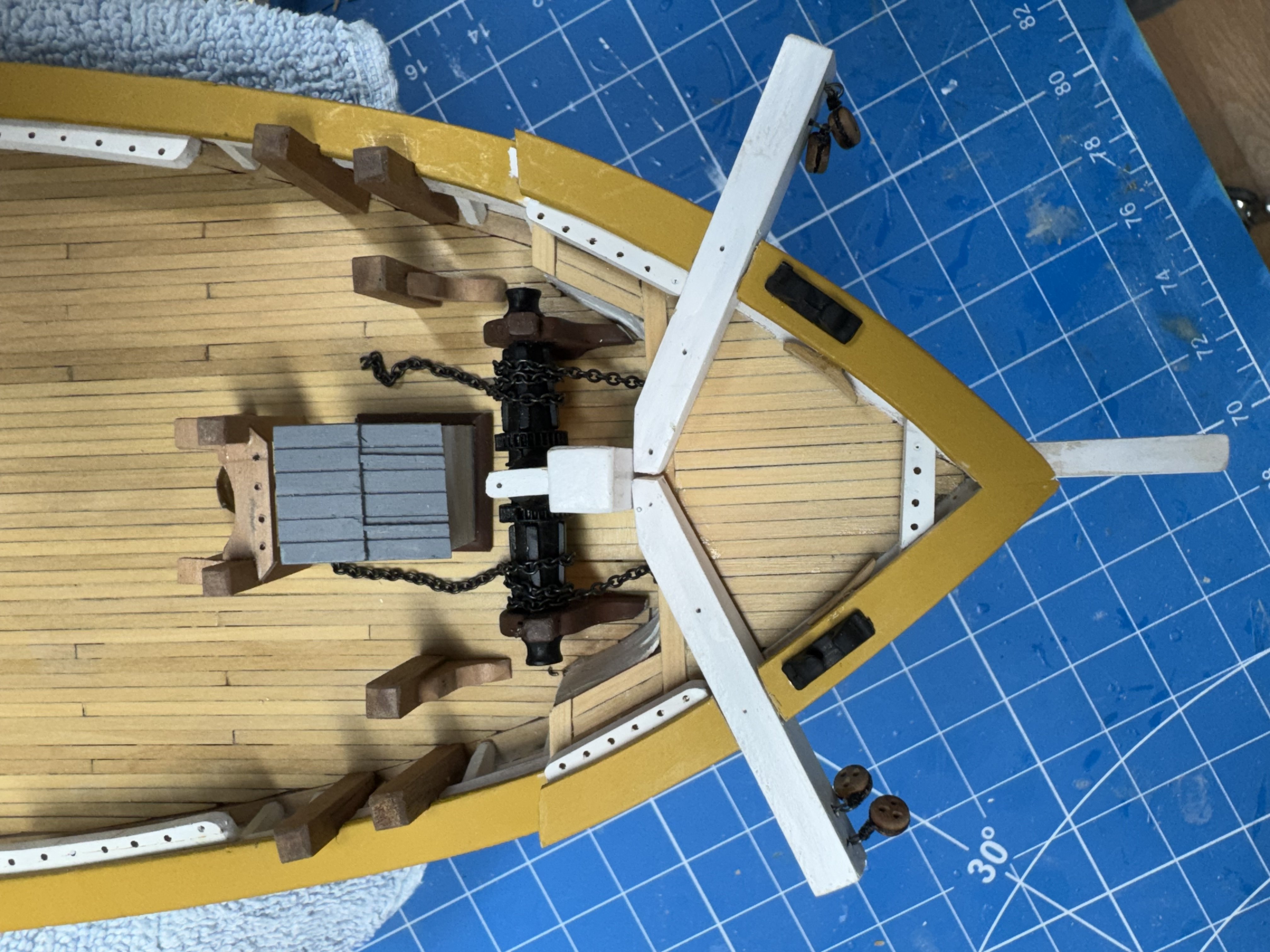
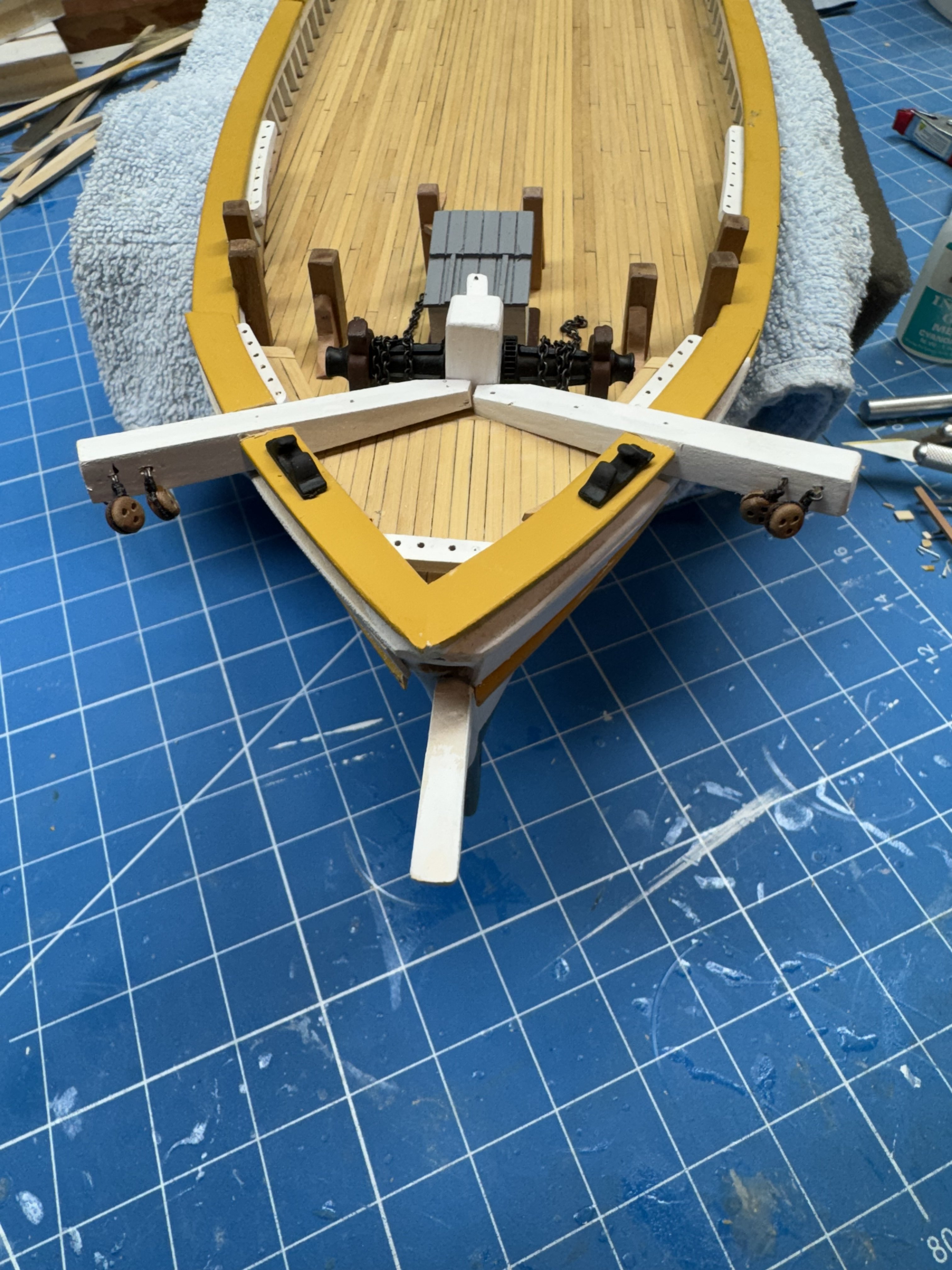
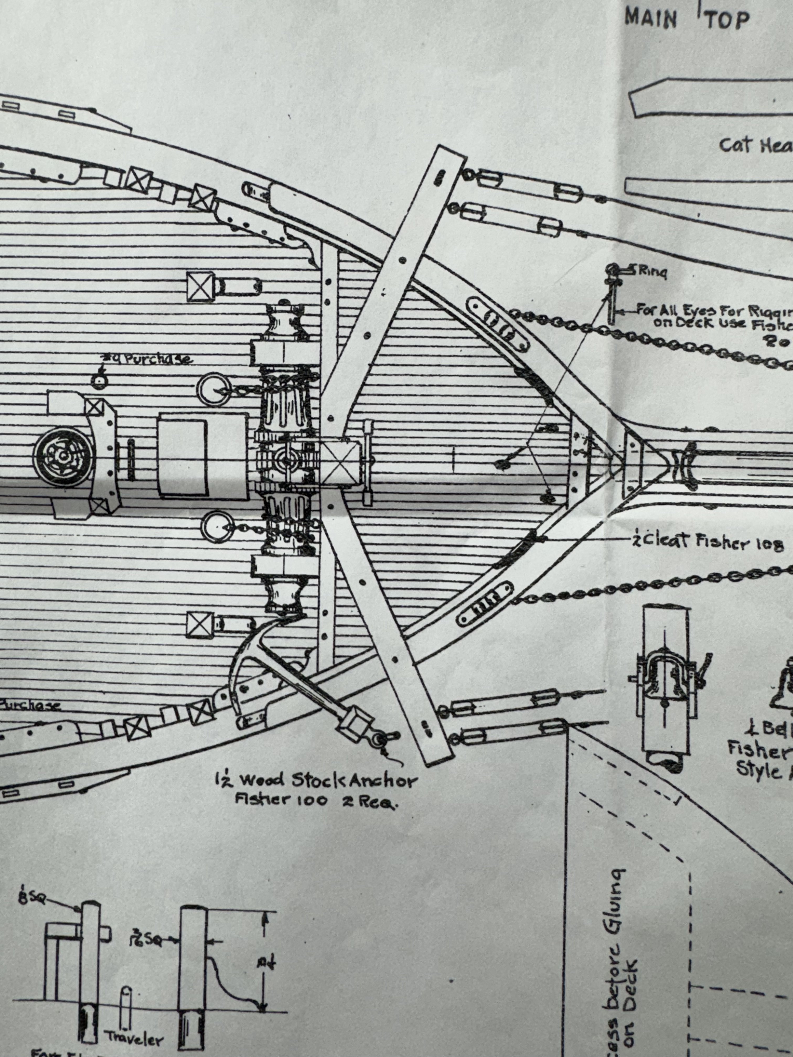
 I guess it is time to start installing some of the "stuff" I have been working on for what seems like a long time. I decided to start at the bow and work aft. First up was the cat heads. Not much drama but you have to be careful when cutting the bulwark to avoid it being too large. I have marked the cat heads for installation of some more plastic bolt heads which are shown on the drawing. The bitts also require some surgery to the deck edge and the timberheads so the bitts will stand up vertically. I have not installed the eyelets to lead the anchor chain to the chain locker because I used the two provided in the kit to clean up the holes where the chain passes through the forecastle to the anchors. The basswood hull material will just NOT take a splinter free hole. I have more 3/16" eyelets on the way and will get to them shortly. Just to be on the safe side, the towing bitts by the forward hatch are just sitting there at the moment so they will not get in the way of drilling the eyelet holes.

- 121 replies
-
- 4
-

-
- Lucia A Simpson
- AJ Fisher
- (and 1 more)
-
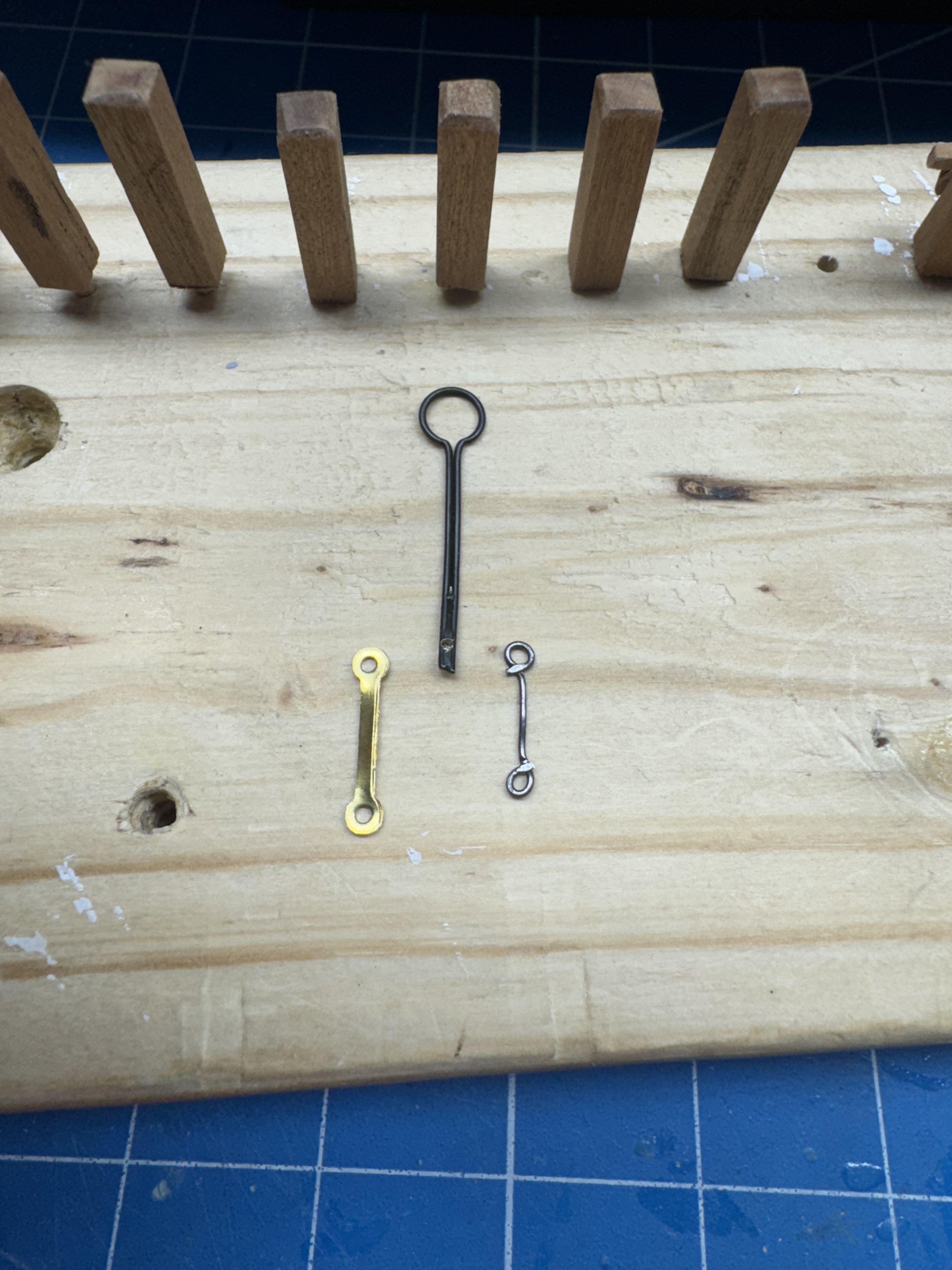
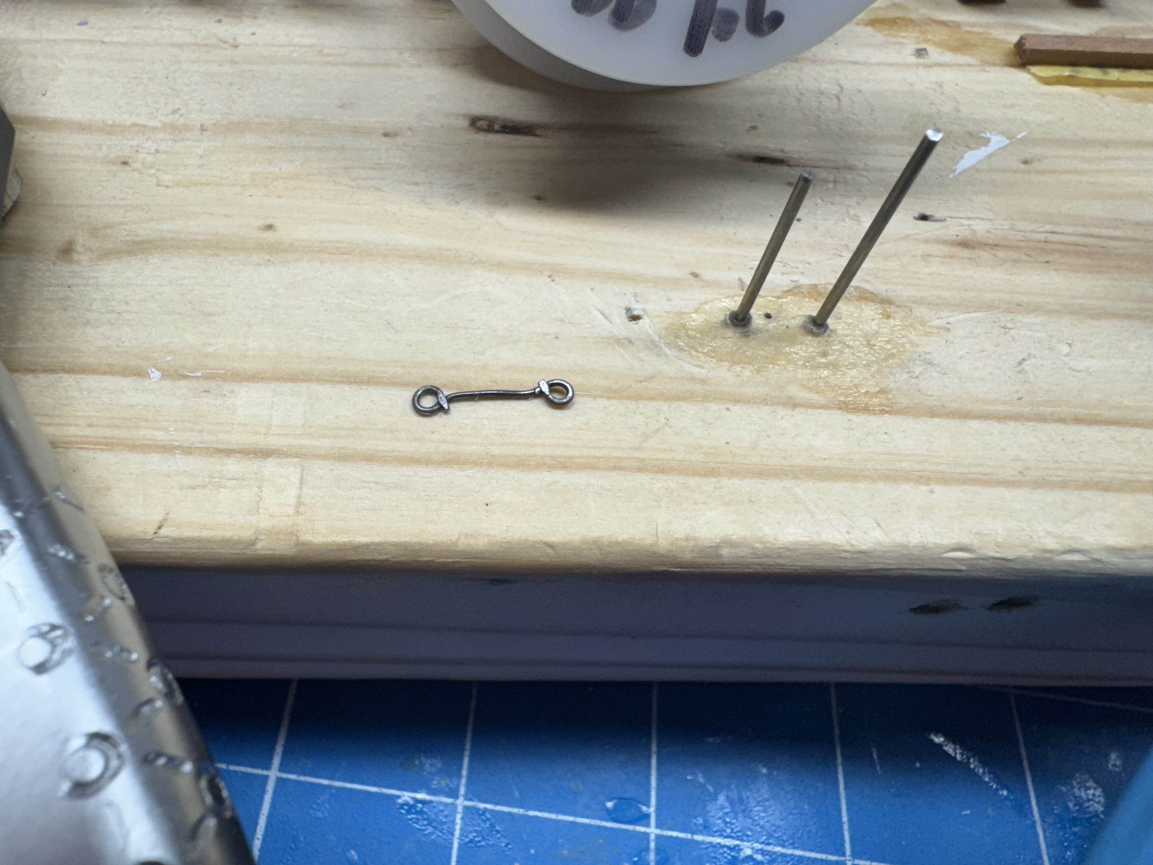
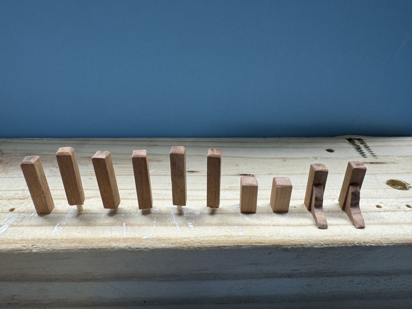
Thanks Rick!😀 After sleeping on it last night I decided that the brass backing links I re-purposed from a different Corel chainplate package were too over scale and looked for alternatives. I set up a little jig (two pieces of .039" piano wire set vertically into a 2 X 4) and tried making the backing links out of 24 gauge annealed steel wire. Actually I tried 22, 24 and 26 gauge wire but decided 24 gauge was "best". Here are the selected chainplate and the two alternative backing links. I made the replacement just a bit shorter (assuming I can replicate the length more or less exactly - yet to be established) so it will (in theory) hit the waterline the same as the drawing shows. One down and 21 left to go.


- 121 replies
-
- 2
-
-
- Lucia A Simpson
- AJ Fisher
- (and 1 more)
-
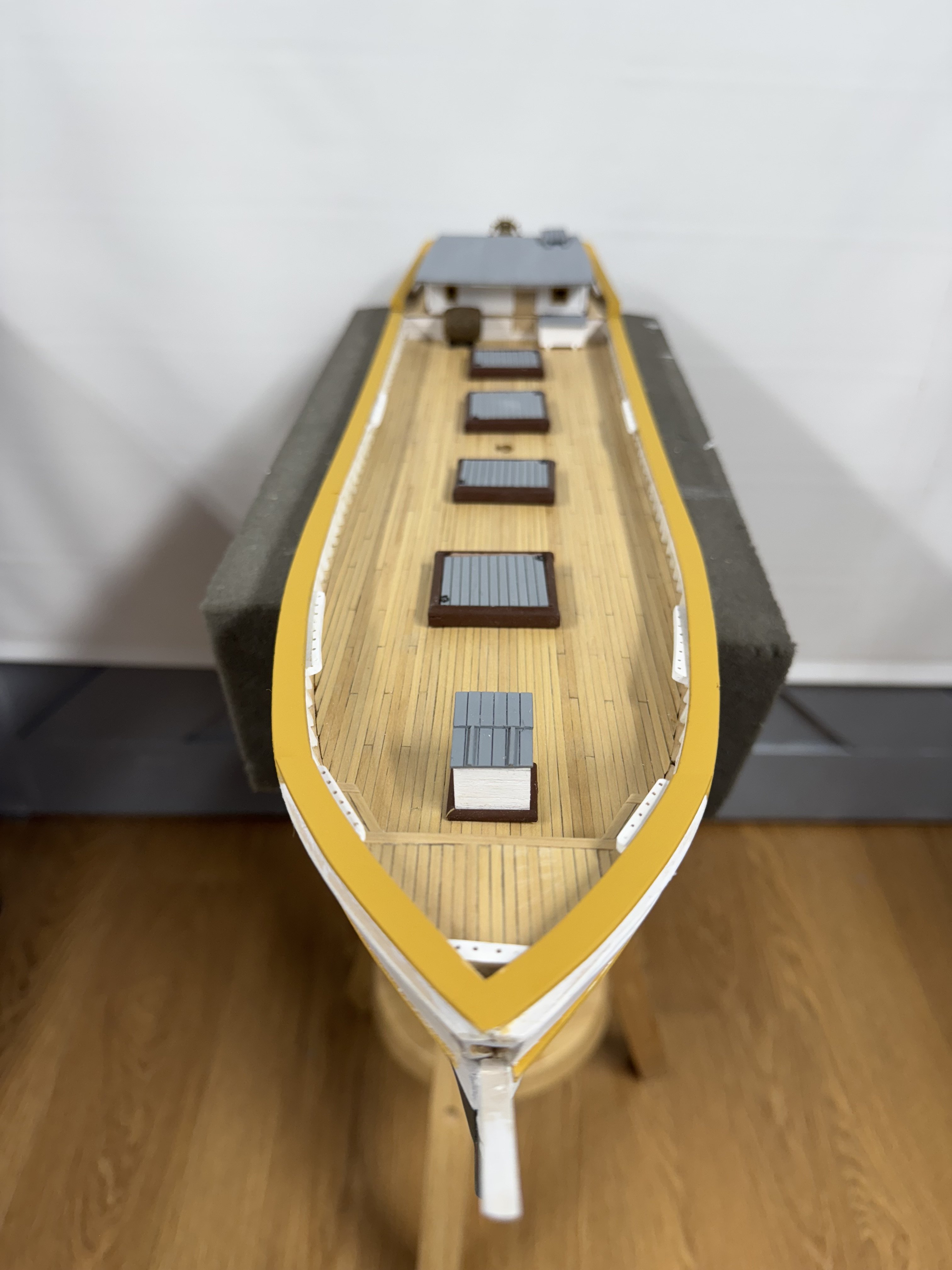
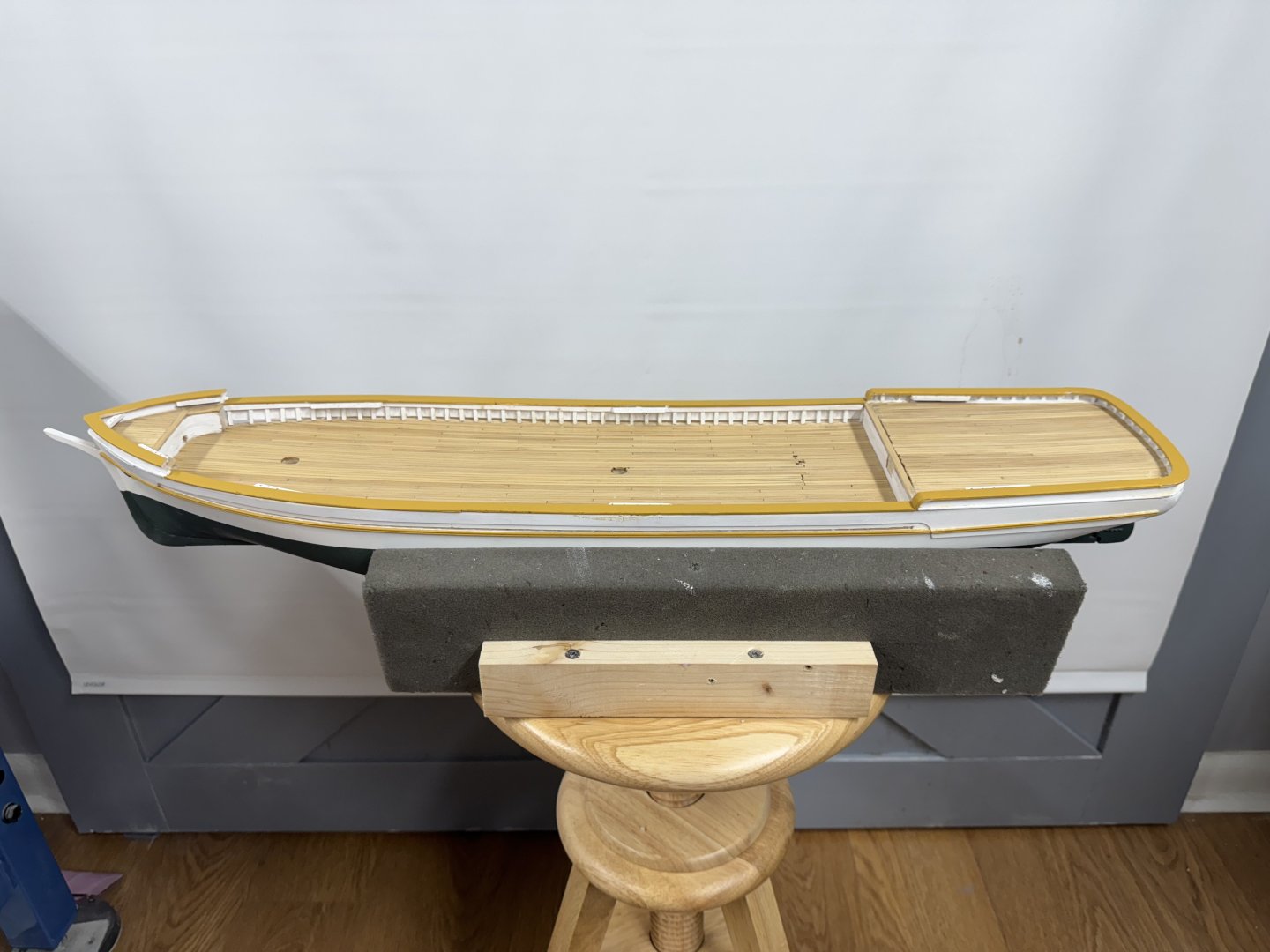
Back to the present. I got all the stern rail and bow splash rail completed and touch-up painted so I decided to take some whole model pictures. And some with what deck furniture is ready for "prime time".


- 121 replies
-
- 4
-
-

-
- Lucia A Simpson
- AJ Fisher
- (and 1 more)
-
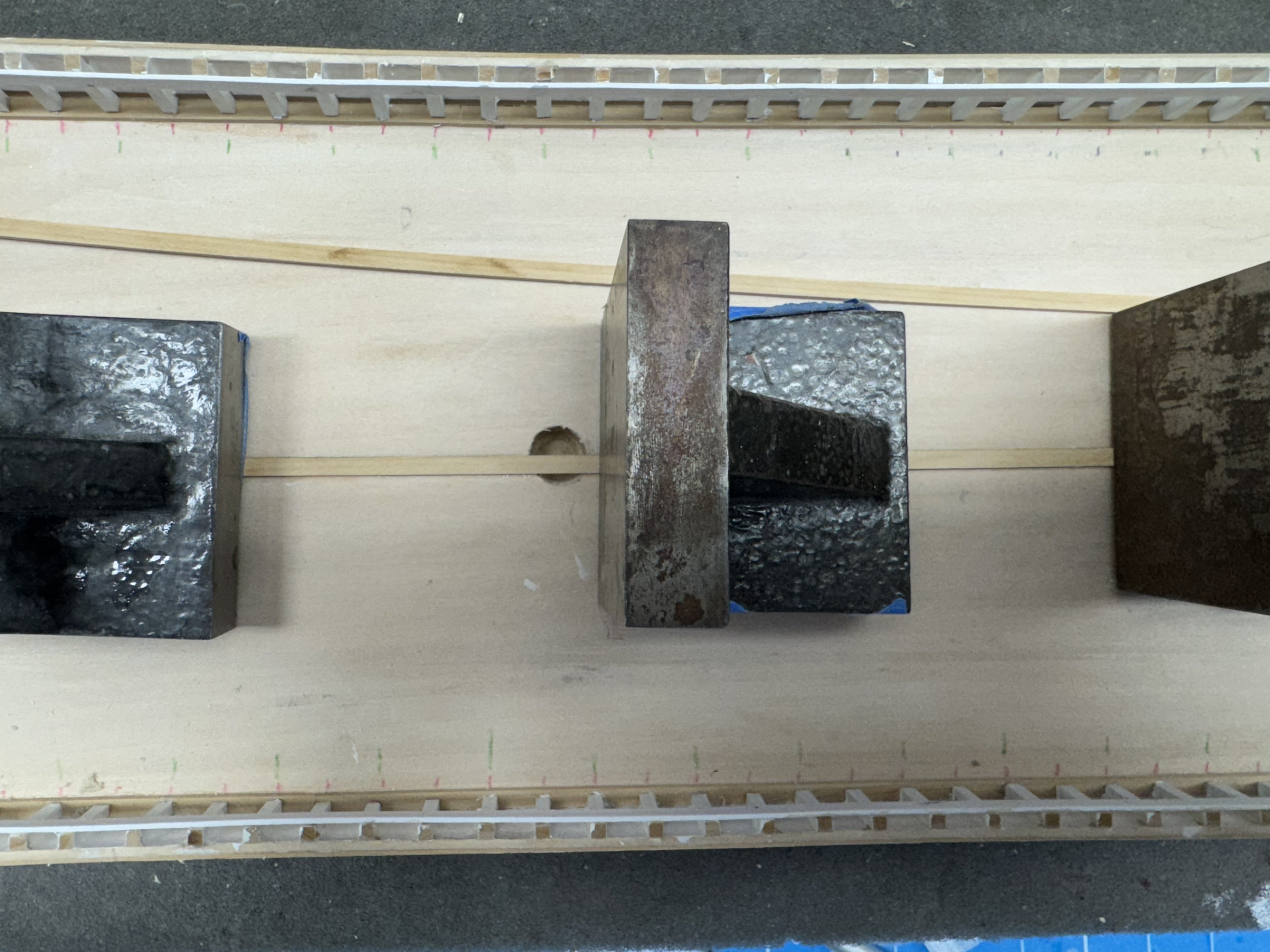
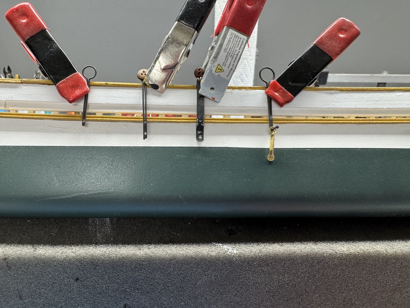
It turns out I have several choices for replacement chainplates. Not sure why or when I got these but when looking through the various "fittings" sites i sometimes buy "stuff" "just in case". It would seem I must have visited the site with chainplates more than once as these all look like they are from the same vendor. I shortened and rebent the kit provided chainplate and drilled two holes (not very well) and that is second from the right. The other three are different sizes of the same design (from Corel I think). On the far right is a potential replacement backing link (suitably blackened/painted) because while the drawing says 22 required the kit only contains ten per the parts list. Any of the Corel chainplates are going to require an upsize in the deadeyes. The two on the left use 5mm and the one on the right 6mm. The kit "large" deadeyes are 5/32' = 4mm (3.968mm according to my converting calculator). I am going with the shortest of the Corel chainplates. I think I have just enough room to bend it down after it clears the molding strip since the channels will be mounted below the cap rail. The backing link is going to have to be on top of the chainplate but I do not see any other solution.
- 121 replies
-
- 2
-
-
- Lucia A Simpson
- AJ Fisher
- (and 1 more)
-
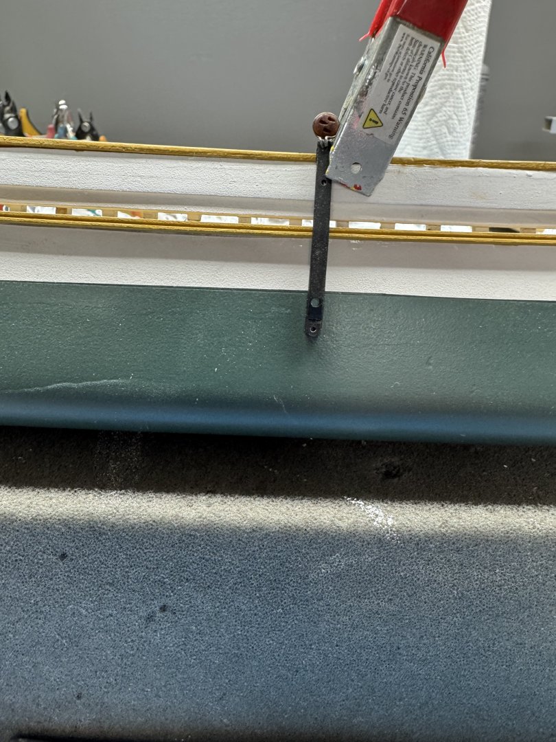
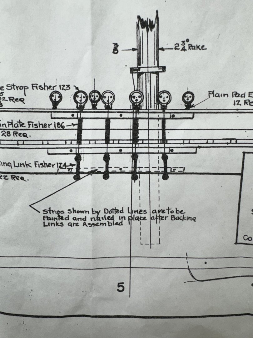
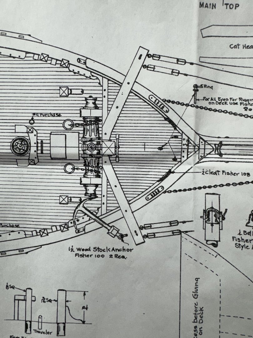
While waiting around for the pin rails which were just installed to get "set" I started looking ahead to the channels. Here is the picture from the plans for the channels/deadeyes/chain plates for the main mast. And here is one of the kit supplied chainplates with a deadeye mounted using 26 ga wire (no mention in the instructions of how the deadeyes are supposed to be attached). I measured and my waterline is within 1mm of where it is shown on the drawing so it would seem that unless I want the chainplates and the backing link down to the turn of the bilge I need to find anther solution. Presently looking through the "parts bin" to see what is available and considering how the supplied chainplates could be modified to be used.
-
Stern mid rail and timberheads in place, masked and ready for seal and paint. Top stern rail has been painted (ocre) and is drying now - probably will need second coat. Transition pieces also in paint drying mode - will definitely need a second coat and probably a third. Bow splash rail pinned in place and has been left to dry over night. Plan to remove (carefully) and seal and paint before reinstalling. Looking for the material for the upper rail as what came with the kit is "lost in space" and I want something a bit wider (to allow my usual set of errors to be more or less correctable) anyway.


- 121 replies
-
- 3
-
-
- Lucia A Simpson
- AJ Fisher
- (and 1 more)
-
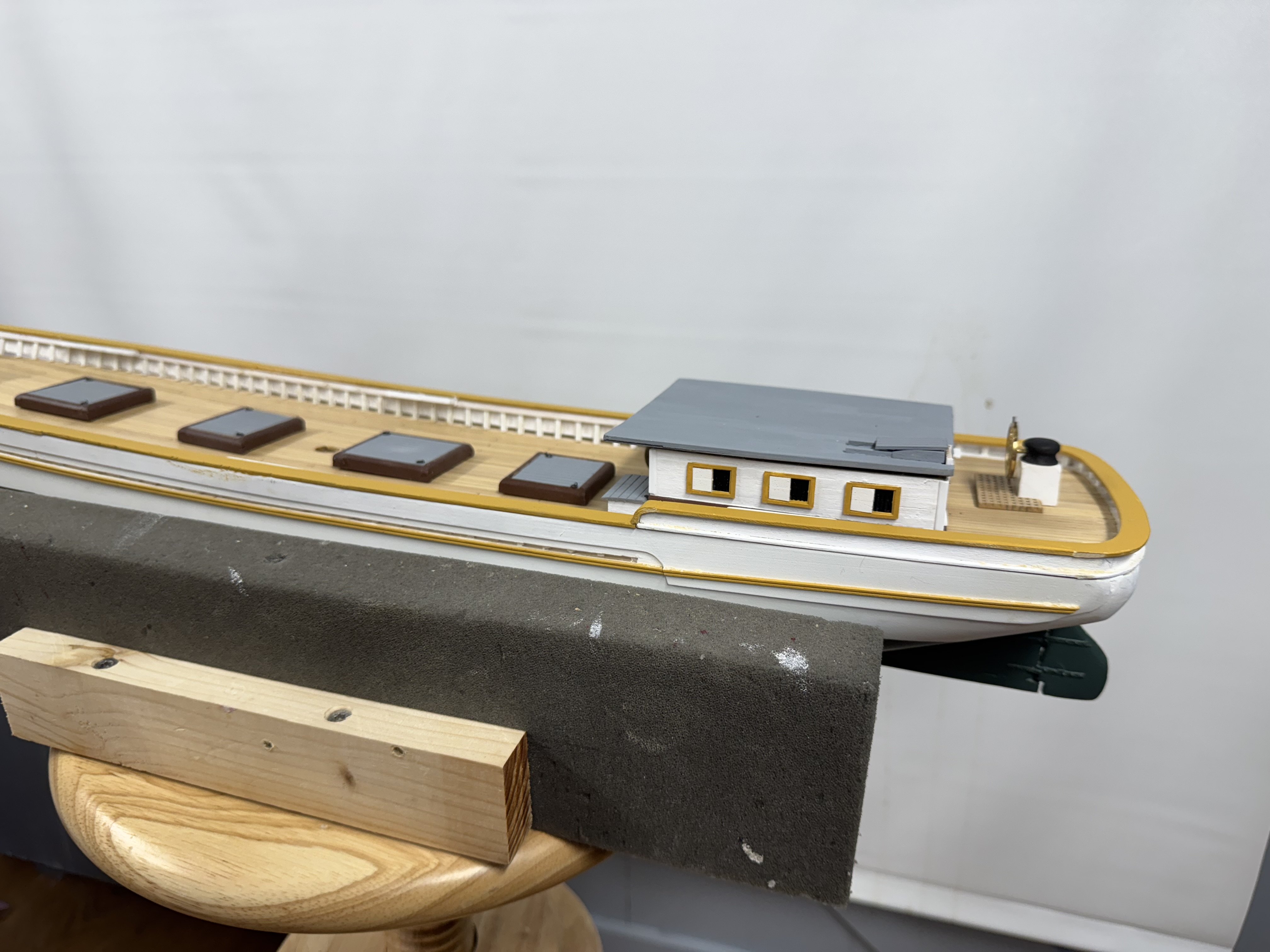
The wheel house now with the Caldercraft 24mm brass wheel which is about 2mm bigger than the Britannia cast wheel provided with the kit. The instructions with the Caldercraft wheel say to paint it walnut but after getting all the nice detailing I did not want to hide it under paint so I just painted the "handles dark brown and will leave the rest brass. I probably also need another coat of black on the upper "housing" and clean the CA off the wheel face - don't want to do too much with the CA solvent as that is what holds the whole thing together..

- 121 replies
-
- 3
-
-
- Lucia A Simpson
- AJ Fisher
- (and 1 more)
-
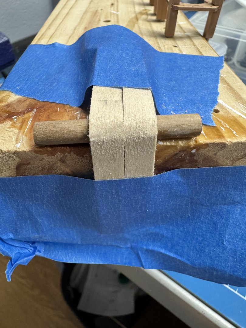
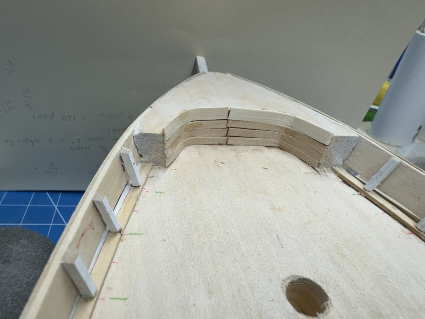
I saw from the drawing that there is supposed to be a curved piece of the stern rail that meets the cap rail to make the transition from the stern rail height to the cap rail. No mention of this in the instructions that I can find. Clearly (to me) there is no way to make 1/16" basswood bend 90 degrees in 3/16" (the height of the stern mid-rail). At least none of the basswood i have will do that; I tried. So I thinned down some 5/16" wide basswood so that it took three pieces to get to 1/16" thickness. Then I built a little jig to hold them in place after soaking in hot water. The jig is below but I used clamps not masking tape to hold them while drying. After they were dry I used 60/40 PVA/H2O to bind the pieces together and then taped them back on the jig to help keep the shape as I noticed they tended to want to unbend a bit if left "unrestrained". I need to paint them orce to match the main deck cap rail then cut them but not until I get the stern rail completed. I also completed the forward fife rail, or at least the forward portion. The drawing shows "legs" under the parts that extend aft of the pin rail but I think I will wait until the fife rail is installed to add them as they will be very vulnerable if they are added now. Here are all the remaining deck items after one coat of Vallejo matt varnish (except the fife rail which is just out of the picture to the right).


- 121 replies
-
- 4
-
-
- Lucia A Simpson
- AJ Fisher
- (and 1 more)
-
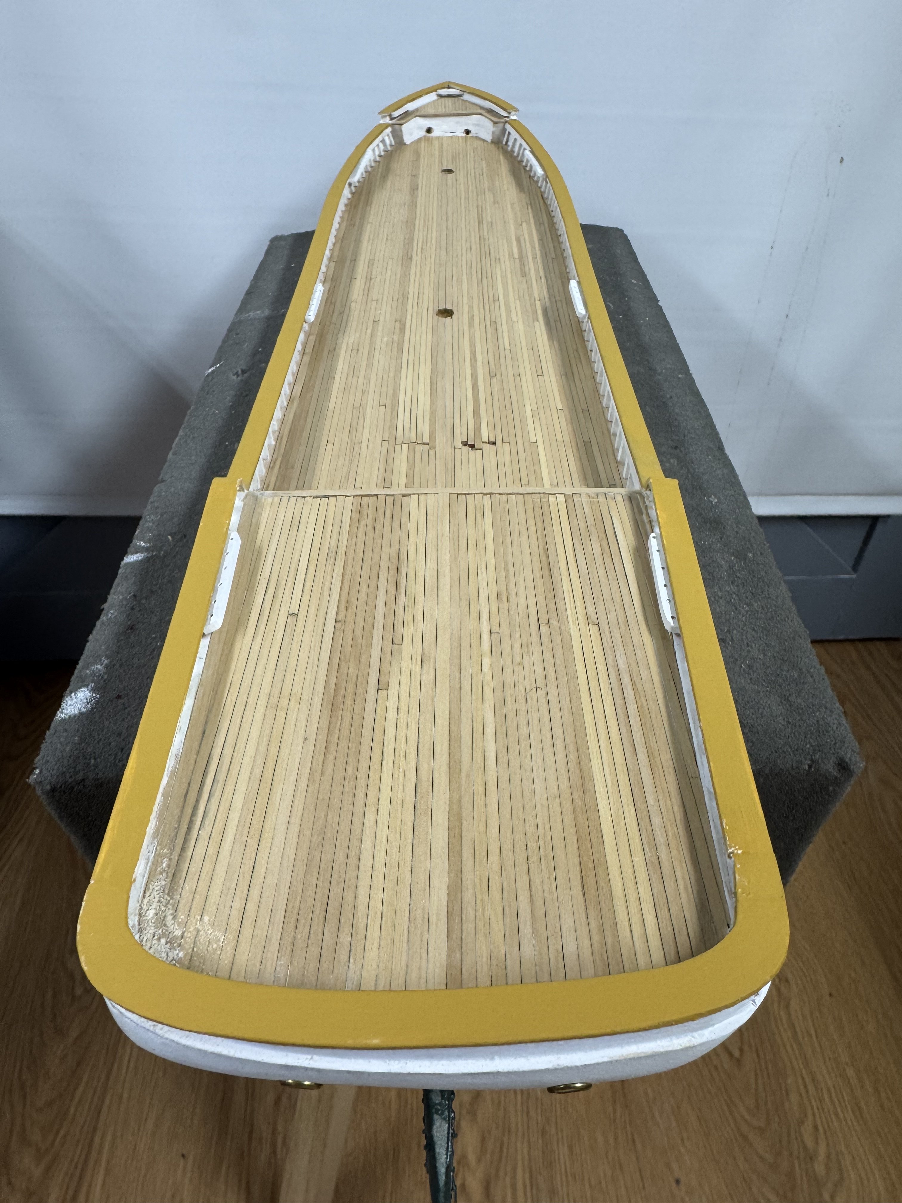
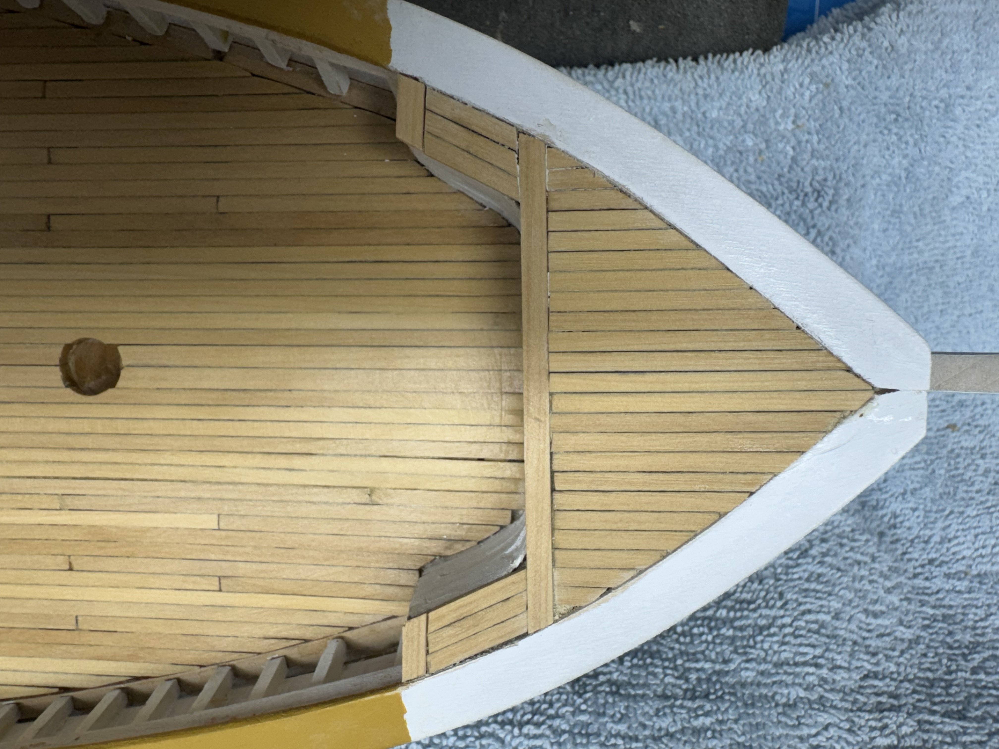
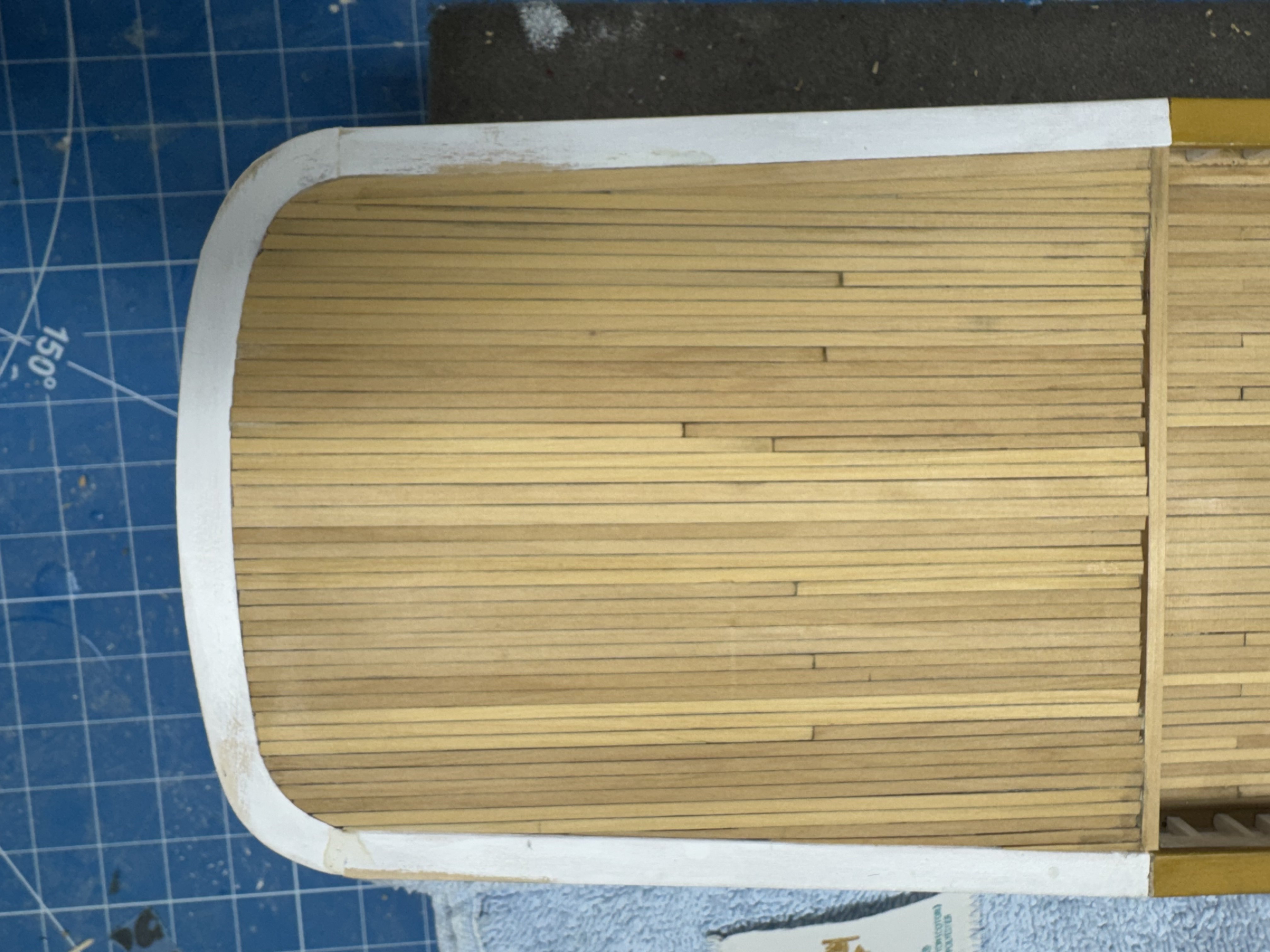
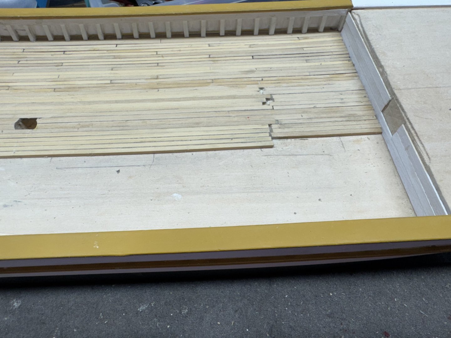
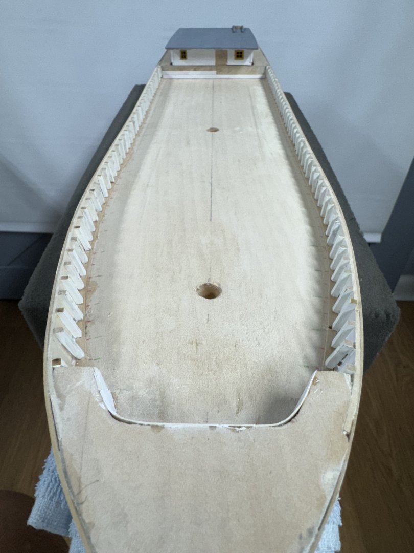
I got the qdeck planked and two coats of WoP. If I had it to do over again I would start at the edges and curve the planks to follow the cap rail. Then they meet in the middle starting at the stern and extending probably about a third of the way forward. As it is I had to make three very sharply pointed pieces on each side. If I had started on the sides the pointed pieces would have been covered, at least partially by the wheel house and associated grating, which, by the way is not mentioned in the instructions either.. I also planked the forecastle using my "best judgement" on how to deal with the unusual shape. it has one coat of WoP now, more to follow. i had to resort to filling in the outboard pieces with sawdust as the space that was left was too small (for me) to be able to cut a very tiny piece and somehow get it into the opening.


- 121 replies
-
- 3
-
-
- Lucia A Simpson
- AJ Fisher
- (and 1 more)
-
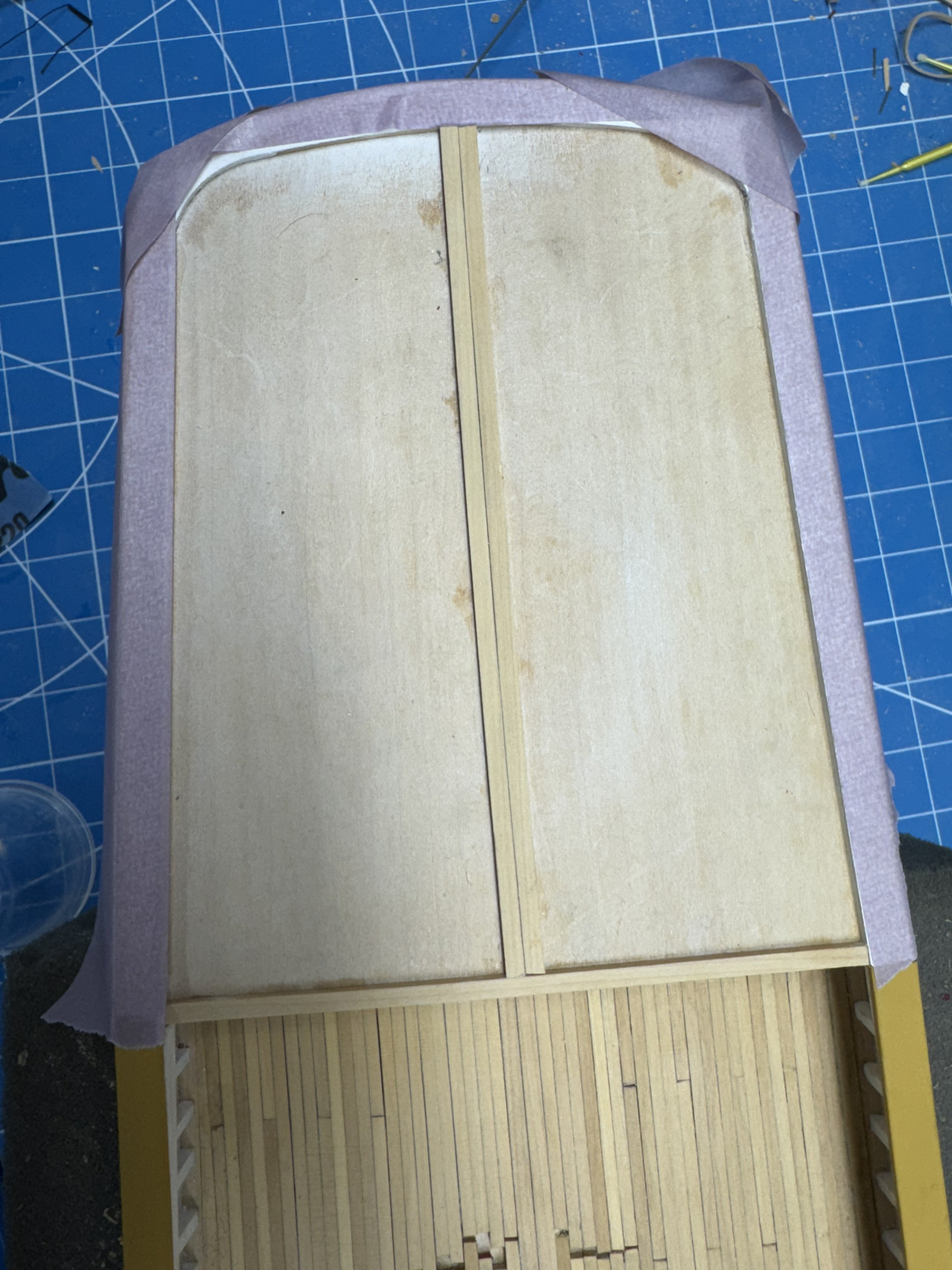
While trying to figure out how to plank the forecastle I decided to work mon the qdeck. Having learned while doing the main deck that graphite from darkening the sides of the planks to simulate caulking is messy, I applied masking tape over the cap rail. The main deck cap rail had to be repainted it was so messed up with graphite (not to mention a few dings and scrapes). So here are the king planks and "end plank" in place ready to start the "real" planking.

- 121 replies
-
- 3
-
-
- Lucia A Simpson
- AJ Fisher
- (and 1 more)
-
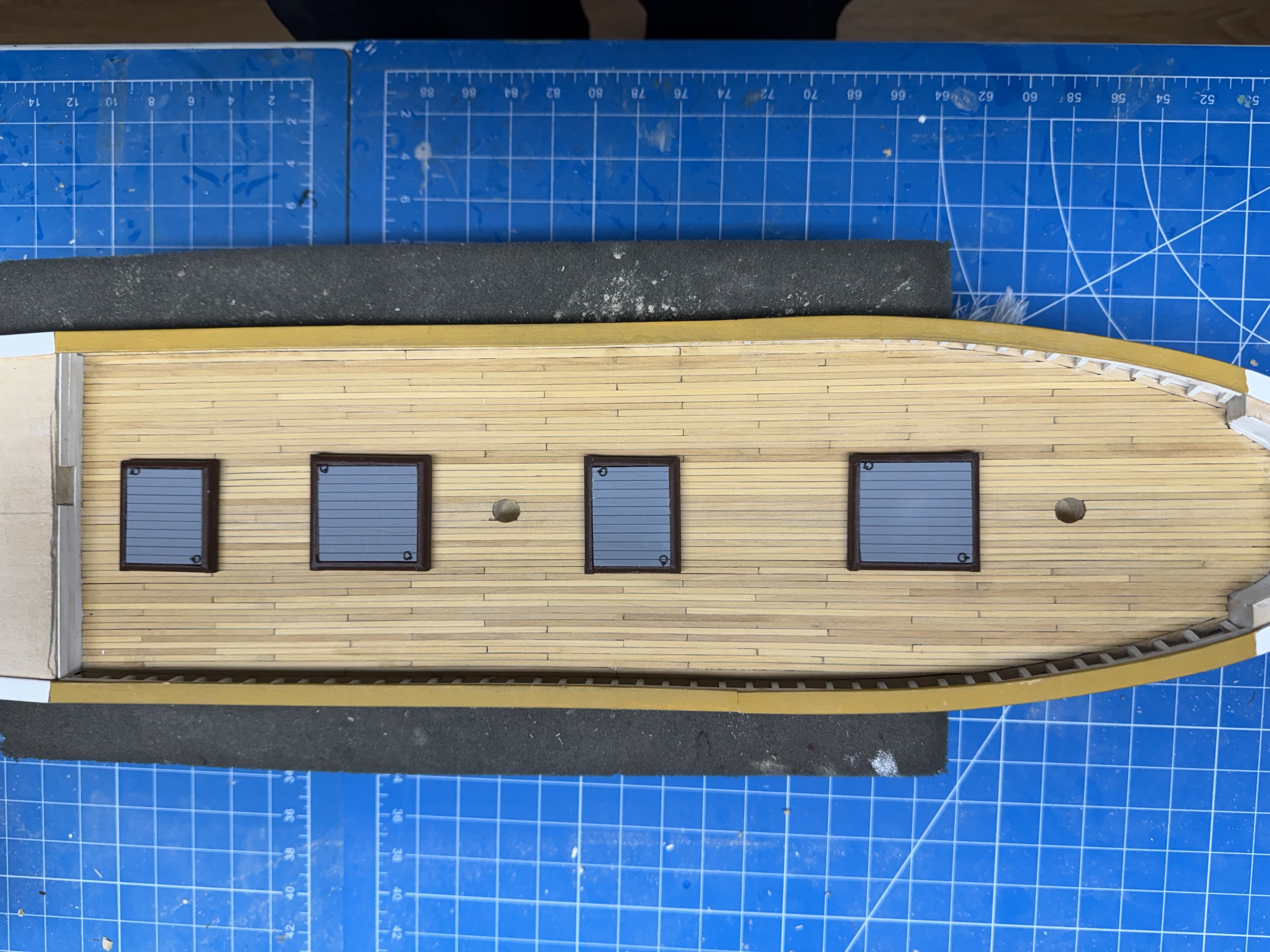
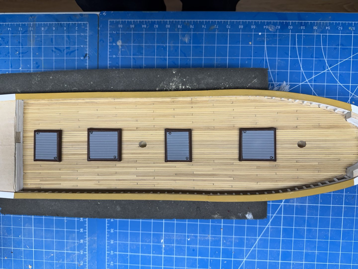
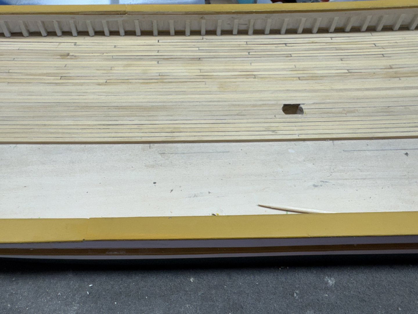
Here is the main deck planking with one coat of WoP. I clearly could have done a better job at color matching the pieces but with a few more coats of WoP the differences will be reduced (I hope). The hatch covers are just sitting there to provide some idea of what the main deck will look like when finished.
- 121 replies
-
- 3
-
-
- Lucia A Simpson
- AJ Fisher
- (and 1 more)
-
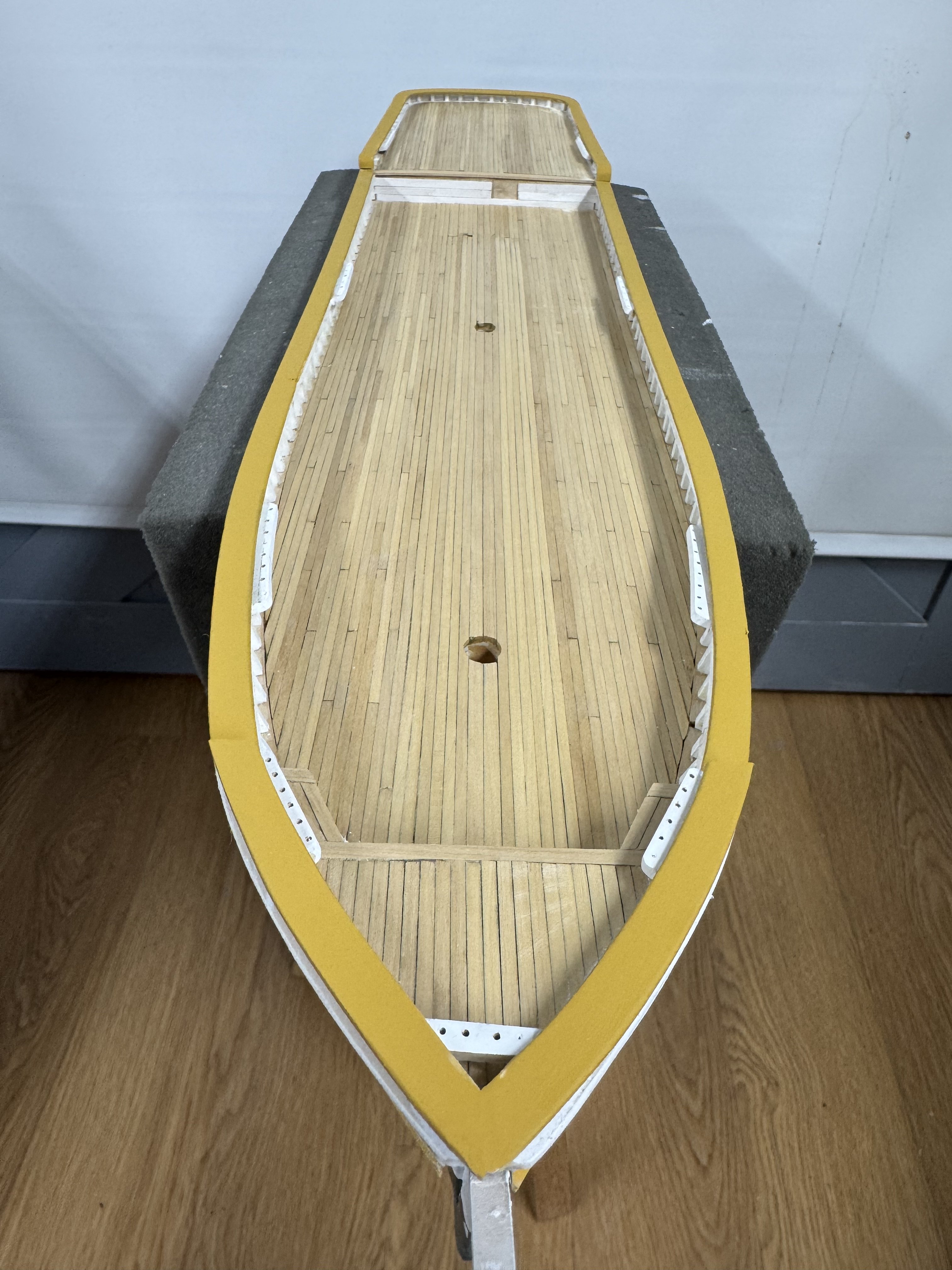
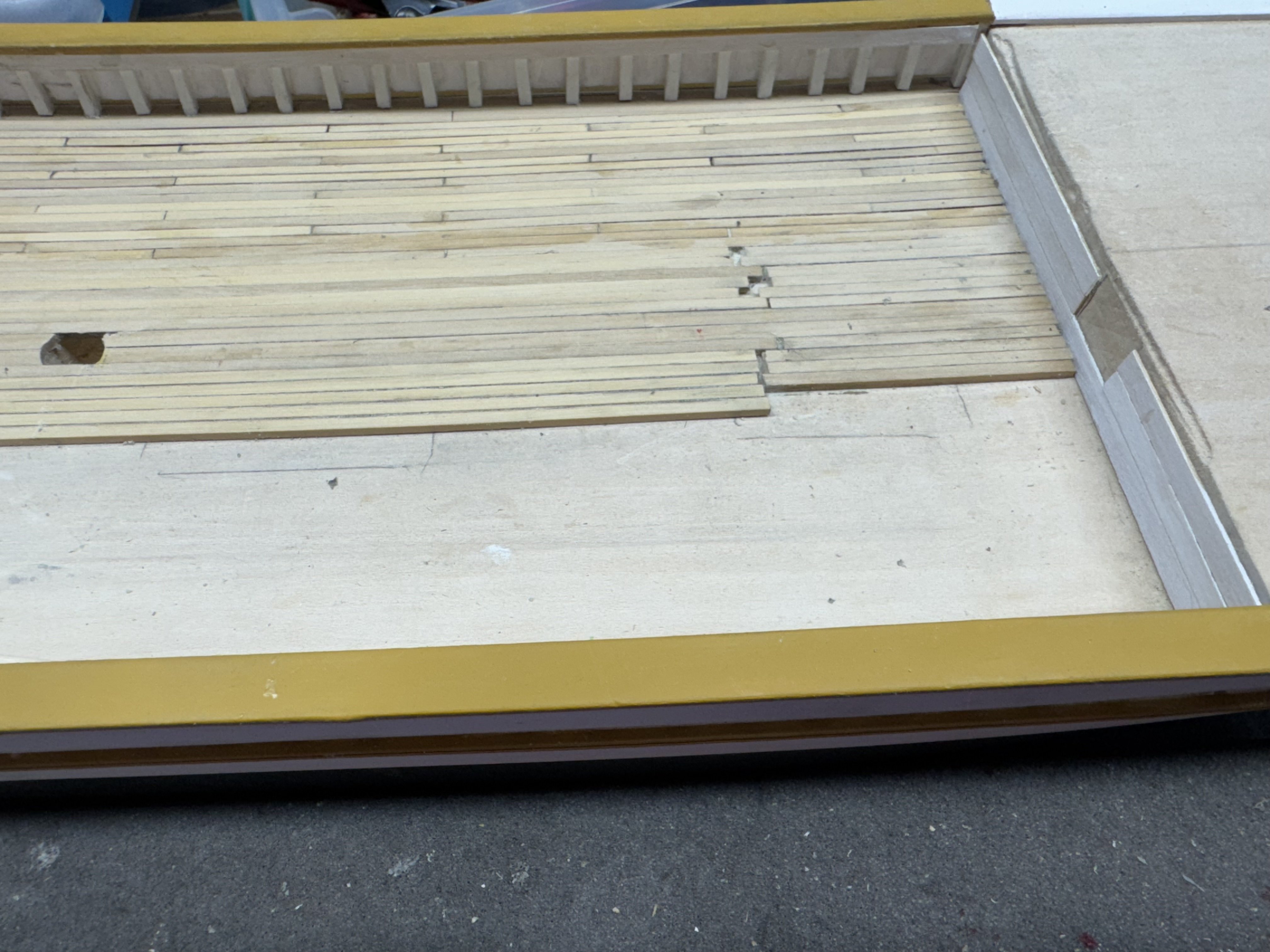
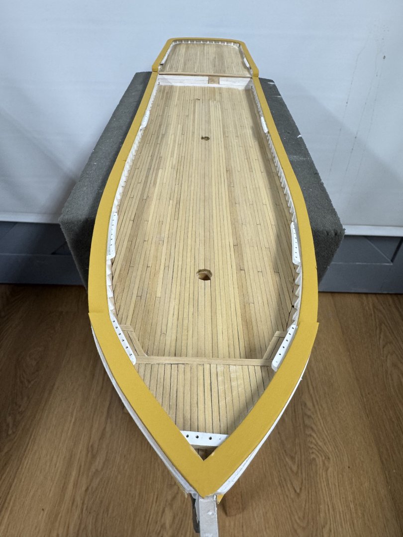
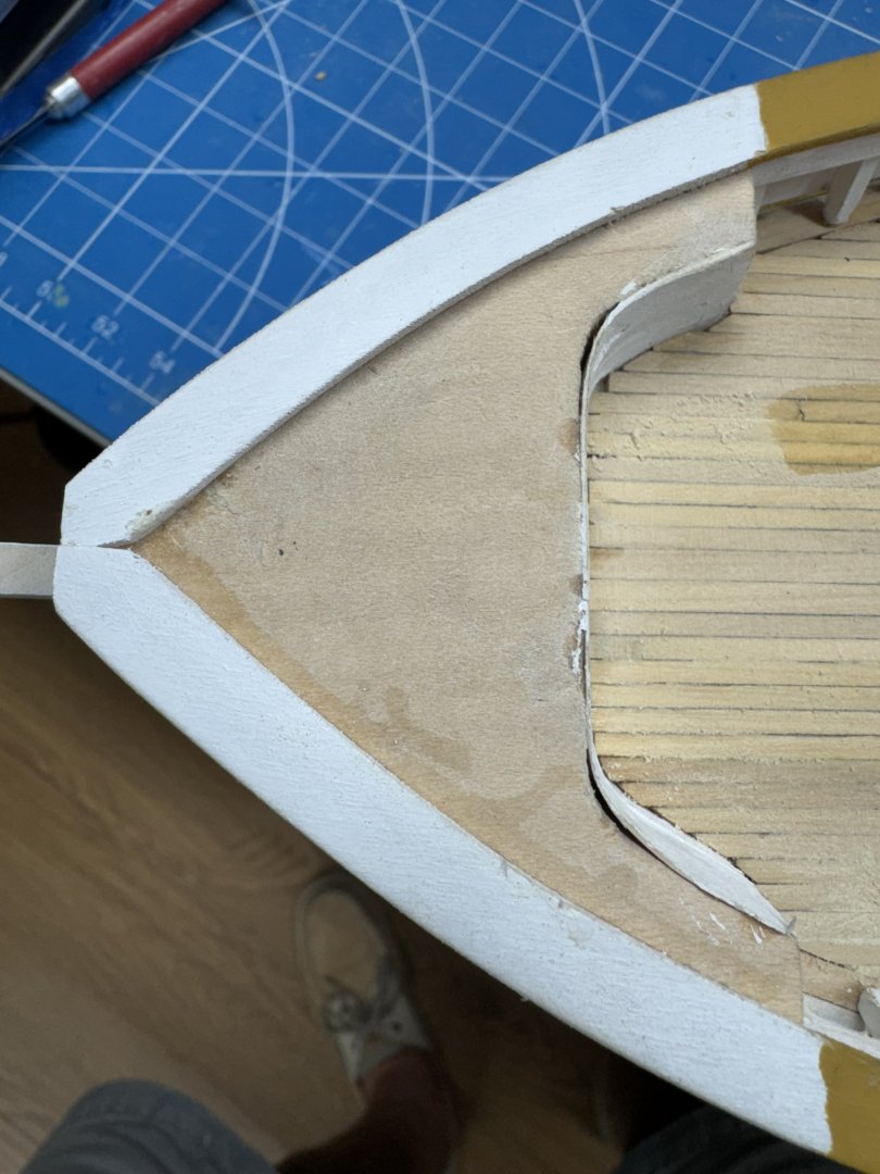
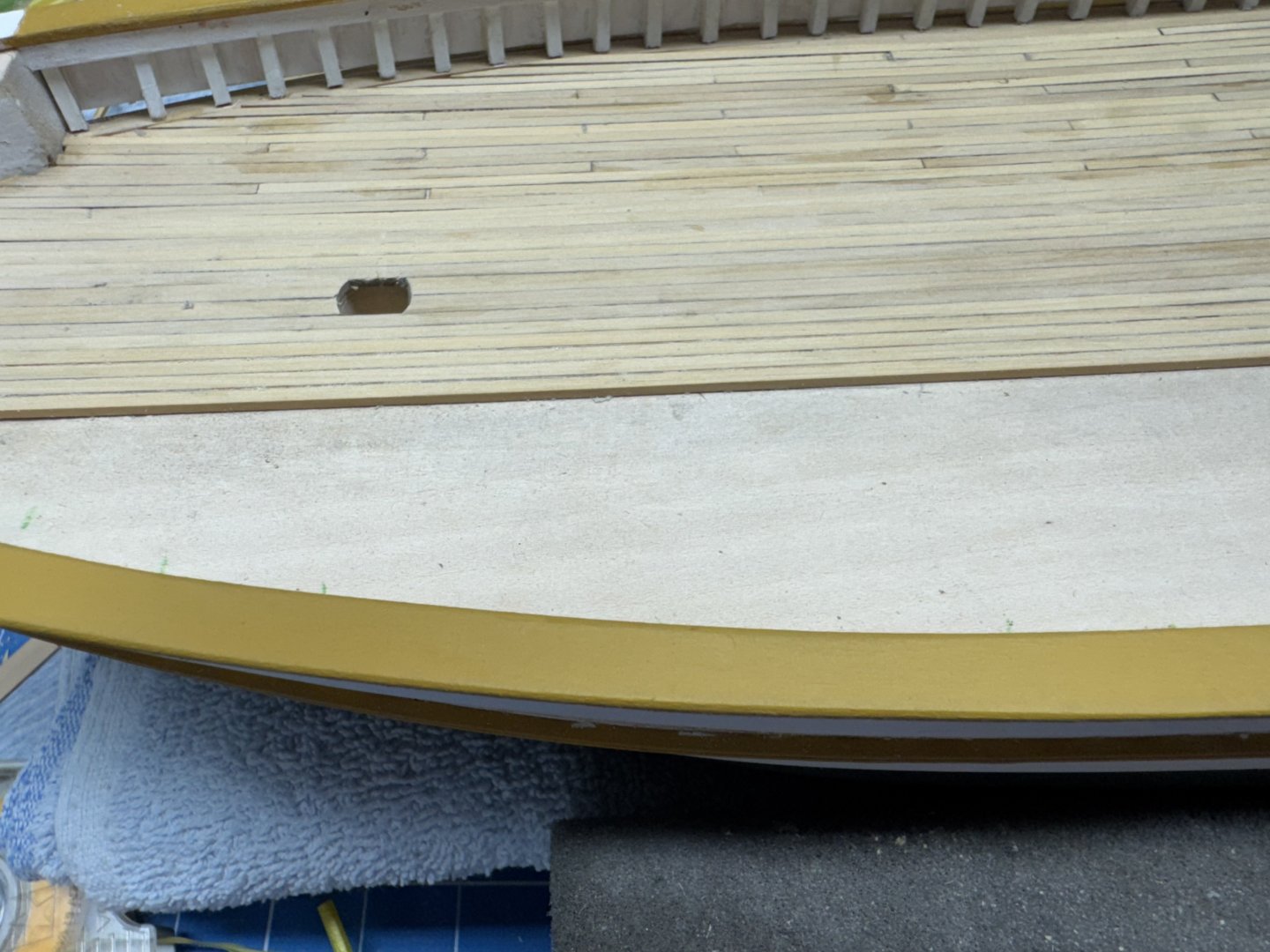
Main deck planking is complete but I will spare you a look at the "mess" while it is being cleaned up in preparation for the Wipe-on-Poly. After doing the main deck I looked at the quarterdeck and forecastle. the qdeck looks like it should not present any problems as it is almost rectangular with a few rounded corners. I am going to use one of the 1/8" wide plonks across the front so I won't have a bunch of plank ends under the deckhouse. The forecastle on the other hand presents quite a challenge and the drawing is no help. The drawing seems to show that the forecastle is one, roughly triangular shape. The reality (as you can see below) is there are two extensions that run aft down either side for about 15mm (5/8"). If I plank it as the main deck with simple fore and aft planks there are going to be some really short, funny shaped pieces on these extensions. To avoid this I am thinking of running three rows of planks along each side of the forecastle (I think I can get the 1/16" X 3/32"boxwood to make that bend without pre-soaking or heat. Might be hard finding some way to hold them in position while the glue dries. I might have to resort to CA. With the three edge rows done then I can cover the rest of the deck (not that there will be much left) with planks running fore and aft. Anyone have another idea (run the planks athwartships?).
- 121 replies
-
- 1
-
-
- Lucia A Simpson
- AJ Fisher
- (and 1 more)
-
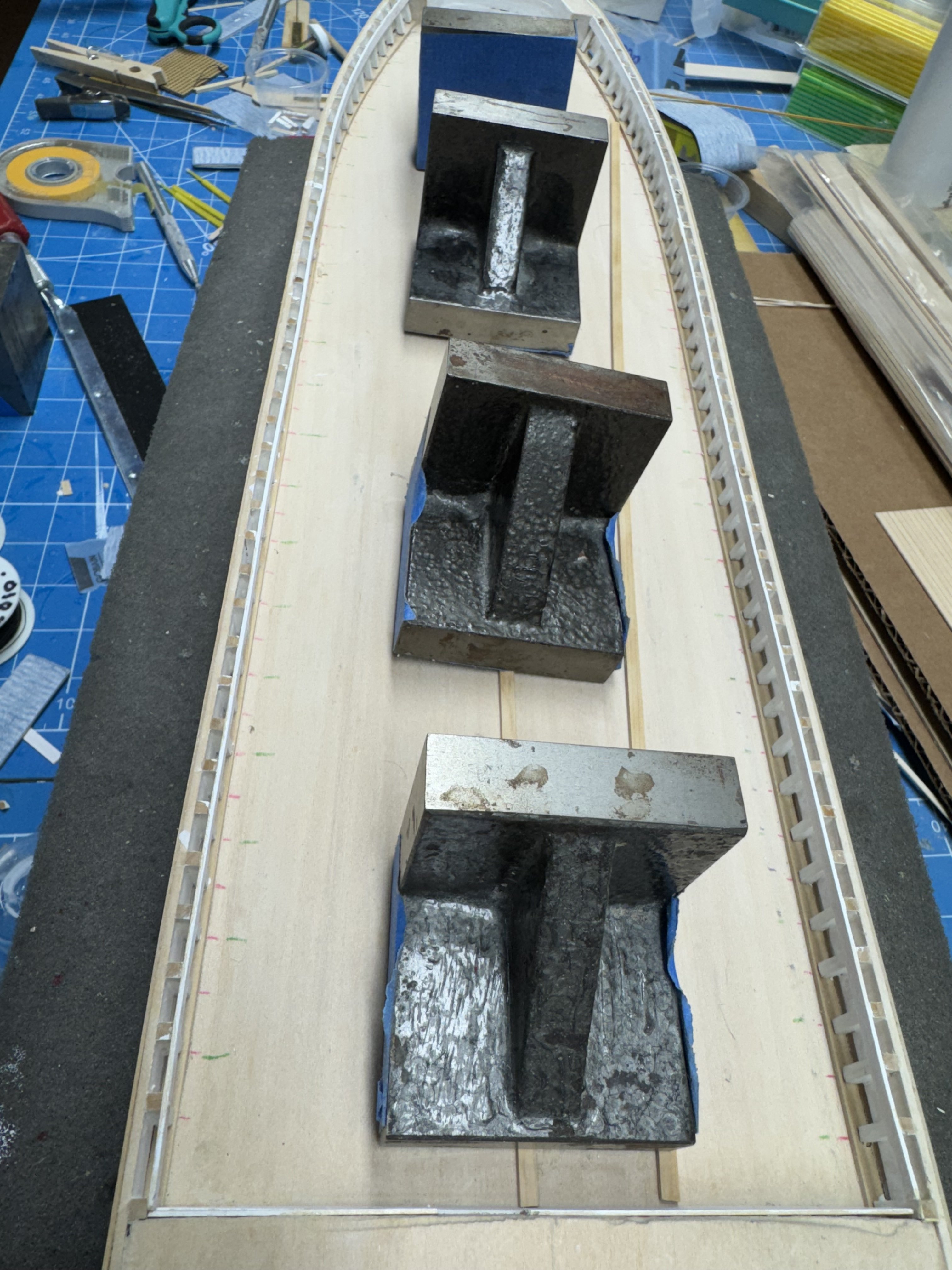
Half the deck (actually a little more) is finished but still needs a good sanding and a few coats of WoP. I started with the 1/8" wide king planks on each side of the centerline. The boxwood material I bought (from Modeler's Sawmill) is 3/32" X 14" long so it would not reach all the way from bow to stern on the main deck. Since much of the centerline area is covered by hatch covers I saw no reason to worry about plank length of sequencing until I reached the outer limits of what the hatches will cover. So I laid down six rows of the 14" lengths on either side of the king planks. And then filled in the area left open to the stern. I did not try and keep the planks continuous since the joint area is covered by the "small" hatch. Outside that area I choose 4" plank length (~22' at scale) and a four drop sequence of plank ends If I had it to do over again I would choose a somewhat shorter plank length as my Byrnes table saw cannot cut something 4' long without removing the rip fence which I am loath to do. In the end I cut each piece as it went on the hull anyway so having pre-cut lengths turned out to really be required. I thought (briefly) about adding another 1/8" wide plank at the outer edge and using that as a nibbling plank but in the end just went with sharp points on the outboard planks. I have not tried a nibbling strake on a solid hull before but remember that it was quite a chore cutting into the nibbling strake on a plank on bulkhead model when the area that required nibbling was on a bulkhead. Here EVERY nibble would be over a solid surface. Maybe if I could figure out a way to not get the nibbling strake glued down except on the very outer edge. In the end I chose the "easy" way. When I got to the outer edge it turned out I needed the extra 1/8" wide strake anyway since the 3/32 would have left a very narrow gasp so having the extra 1/8" pieces really worked out.
- 121 replies
-
- 2
-
-
- Lucia A Simpson
- AJ Fisher
- (and 1 more)
-
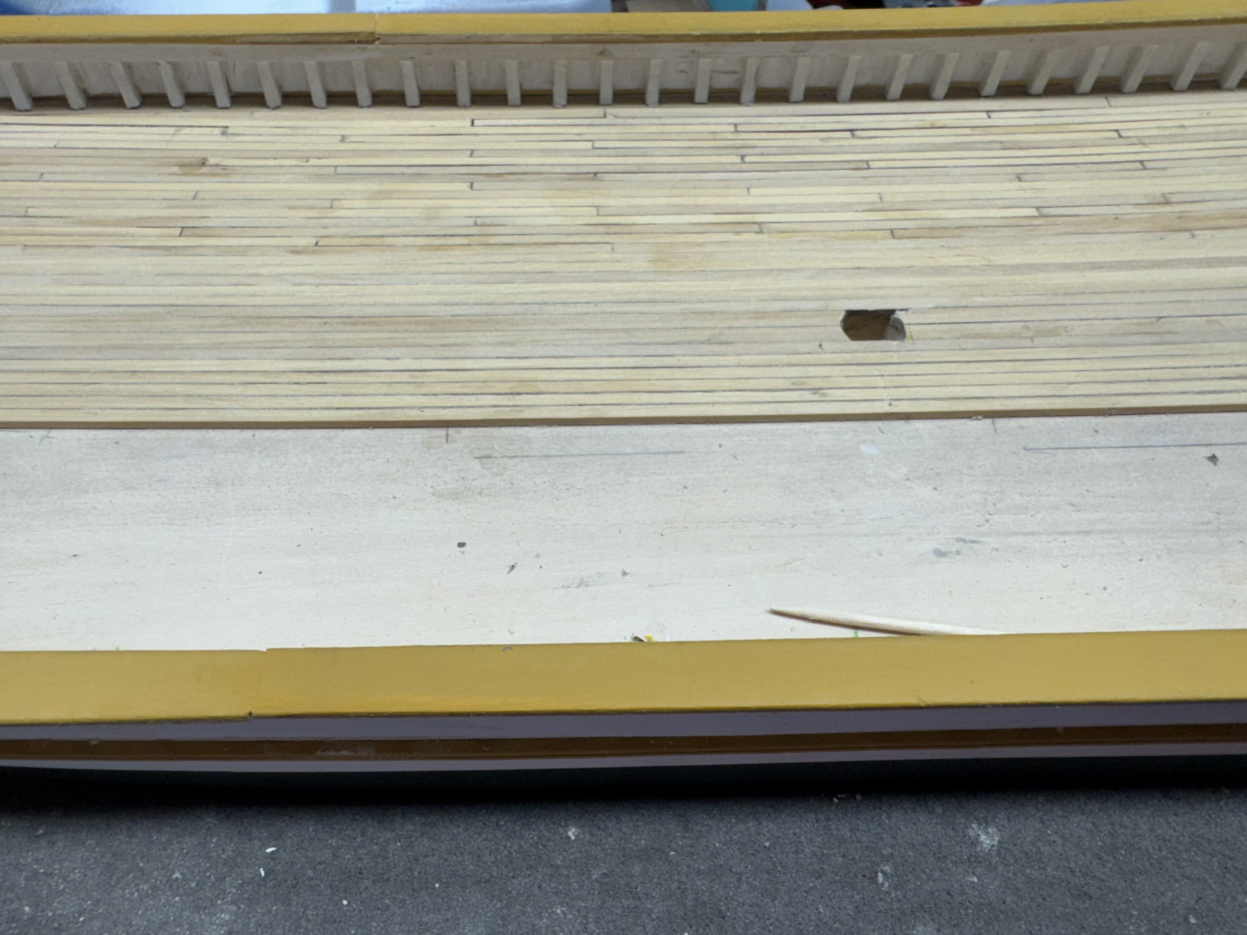
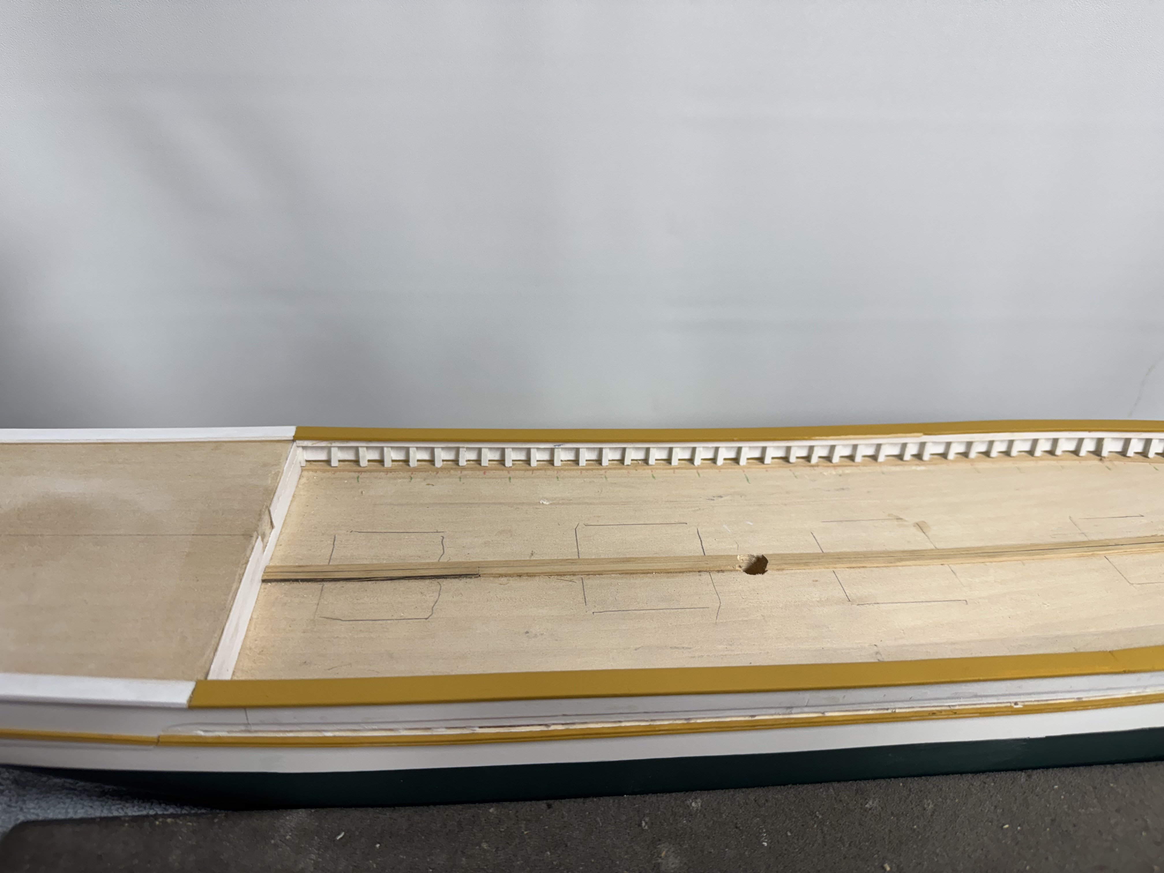
I got the cap rail completed on both sides - now on to the main deck planking. In case anyone is wondering the two-tone paint job on the cap rail is because I want the upper rail to be ocre not white. Since there are rails above the cap rail at the bow and stern I chose to paint those portions of the cap rail white and will use ocre on the stern top rail and bow splash rail so there will be a continuous "ocre line"when viewed from above. The pencil lines are approximately where the hatches will go. It appears there will be six or seven rows of planks on either side of the king planks before I have to start worrying about plank length and stagger.
- 121 replies
-
- 3
-
-
- Lucia A Simpson
- AJ Fisher
- (and 1 more)
-
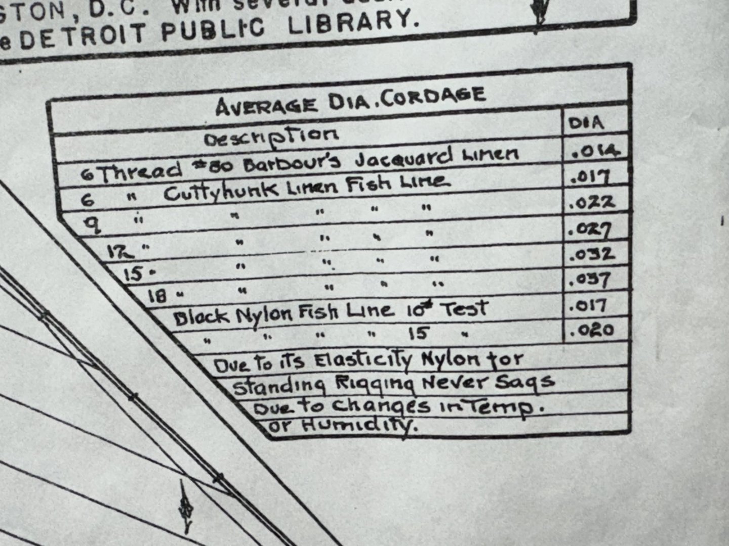
While reading through the instructions for the third time I noticed sort of in passing that the double blocks under the booms are supposed to have a becket for the standing end of the boom sheet lines. No mention of this on the drawing so I got the booms out of the "To Be Installed" box and added a becket to each block. Having done that I wondered about what size line should be attached as the booms will be lashed down with the furled sails and gaff on top so getting at them to run the line later is unlikely to be successful. There is a table on the rigging sheet (sheet 2) that purports to cross from the cordage descriptions in the rigging table (#40 Linen for example) to diameters. Unfortunately the description in the table and the running rigging table do not correspond (the rigging table uses numbers like 30, 40, 100). So just looking at the diameters it looks like the running rigging called out is very "heavy" based on building a number of ships at this scale. I am going to use the Syren Ultra line for this build (I have a bunch of it) and I have never dealt with nylon fishing line - monofilament but not nylon. The question is what sizes to use. The standing rigging table gives diameters so that is easy - just pick the Syren size closest to what is in the table. For the running rigging (even though the kit only has two sizes of tan line which are approximately .009" and .014" in diameter) the major hauling parts .018", the minor hauling parts and the tackles supporting the major hauling parts .012 and for downhauls and other minor lines the .008. I am going to use the .012' for the booms and attach the line before the booms go aboard.
-
My intent is to get the cap rail installed and then plank the main deck I wanted to get a "head start" and get the king planks laid while waiting for the cap rail paint to dry. The center line planks are 1/8" wide while all the rest will be 3/32 (6" at full scale) and about 4" long (22' at full scale). Since there are no "opening below" I am going to just have the hatches sitting on the decking rather than gluing down the hatches and planking around them. Here is the first king plank in place and weighted down while the glue sets.


- 121 replies
-
- 3
-
-
- Lucia A Simpson
- AJ Fisher
- (and 1 more)
-
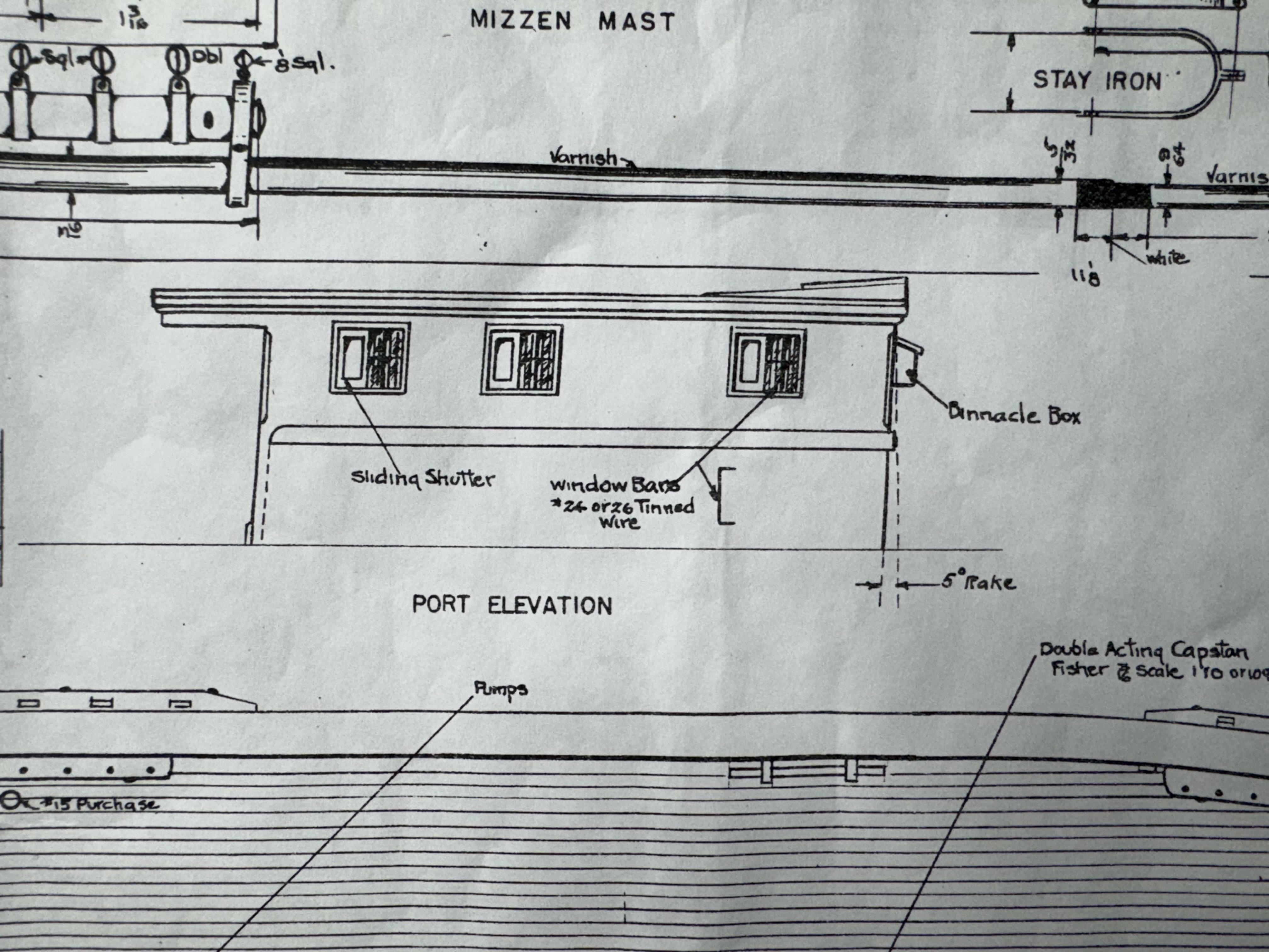
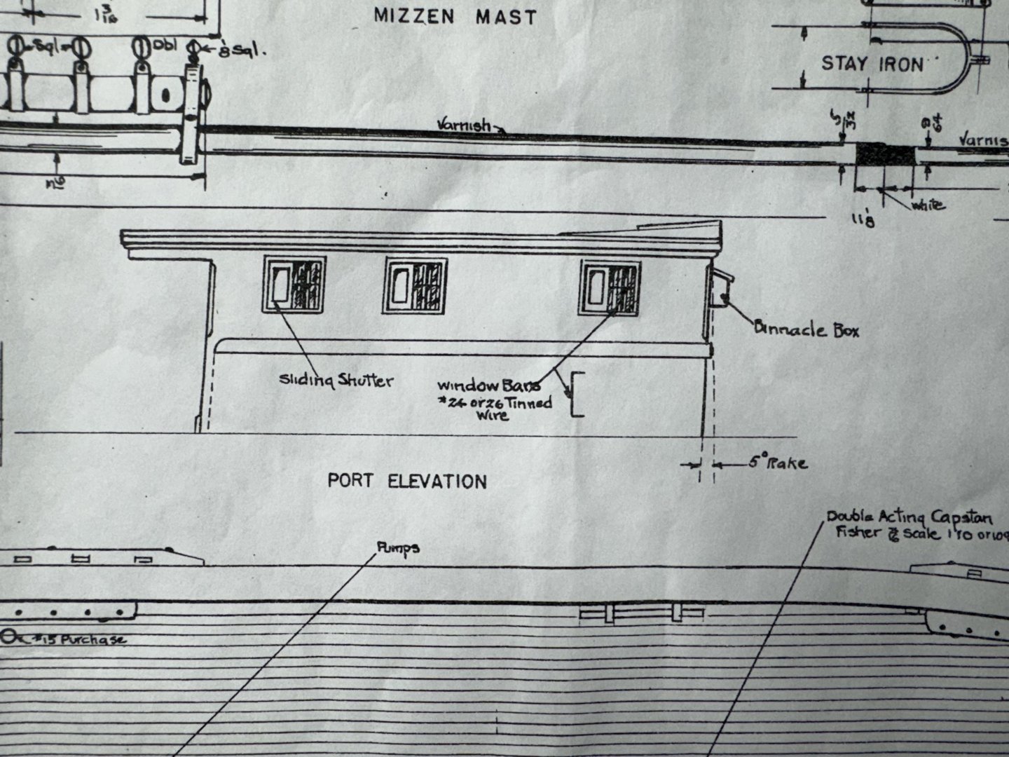
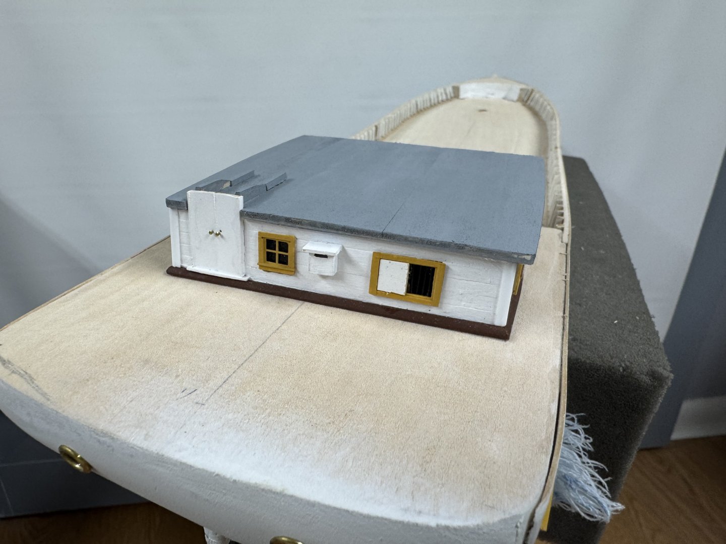
Thanks Jacques. Even more interesting (to me) is that the entire deckhouse is racked aft 5 degrees according to the drawing. I made no attempt to model this as the forward portion is partially the machines hull. I doubt anyone will notice.
- 121 replies
-
- 3
-
-
- Lucia A Simpson
- AJ Fisher
- (and 1 more)
-
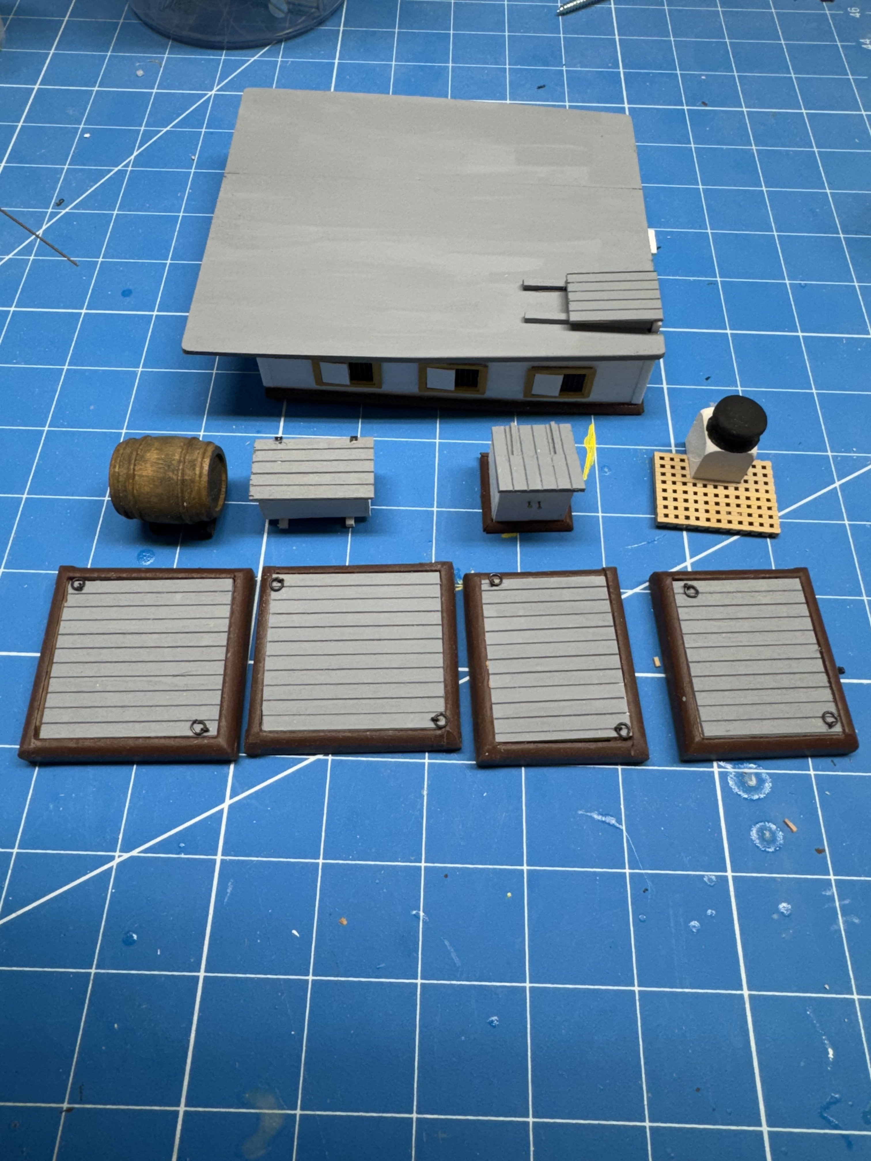
Nine pieces of the deck furniture are complete (more or less for the deckhouse) and headed for the "To Be Installed Later" storage bin.

- 121 replies
-
- 6
-
-
- Lucia A Simpson
- AJ Fisher
- (and 1 more)
-
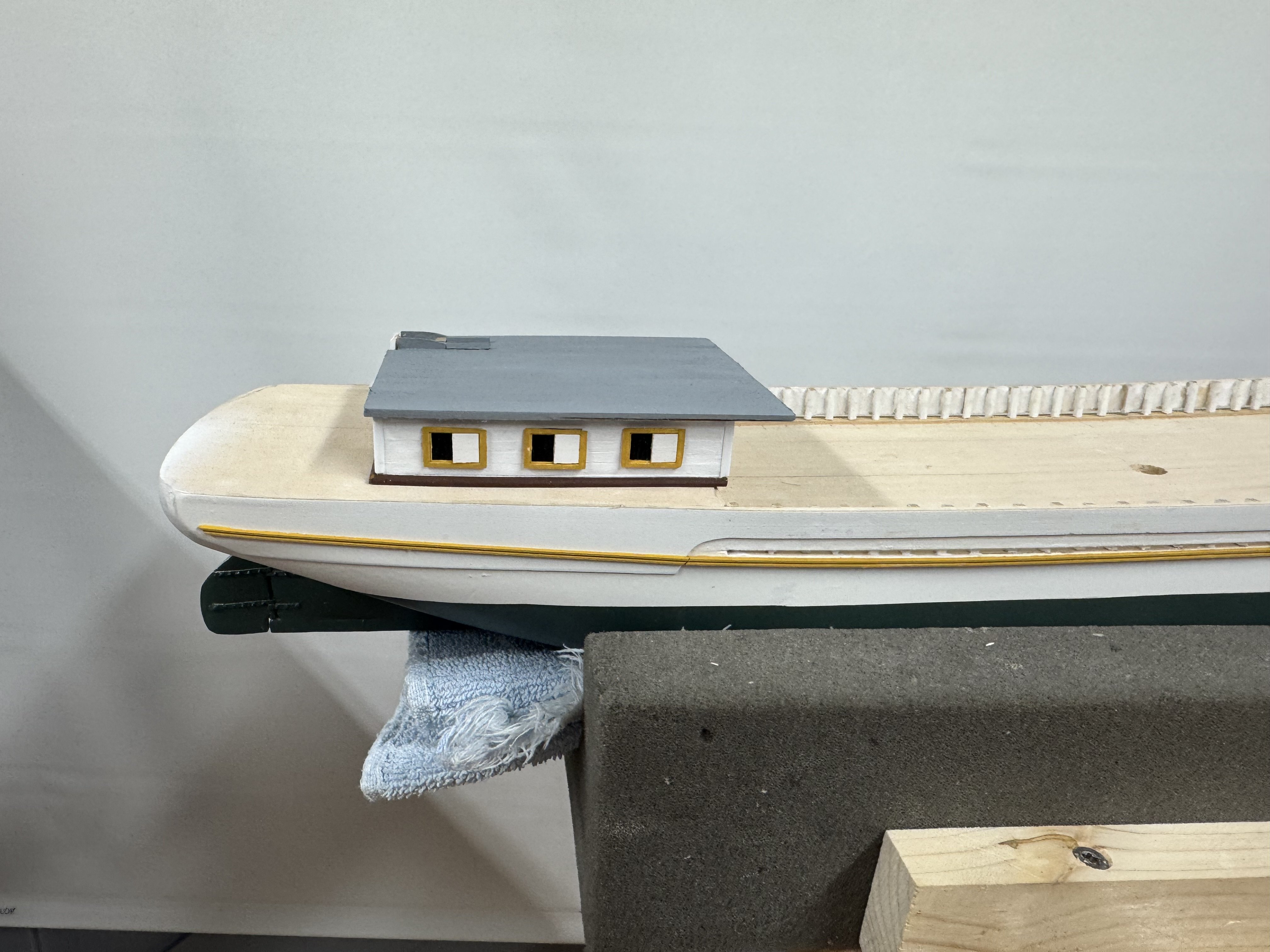
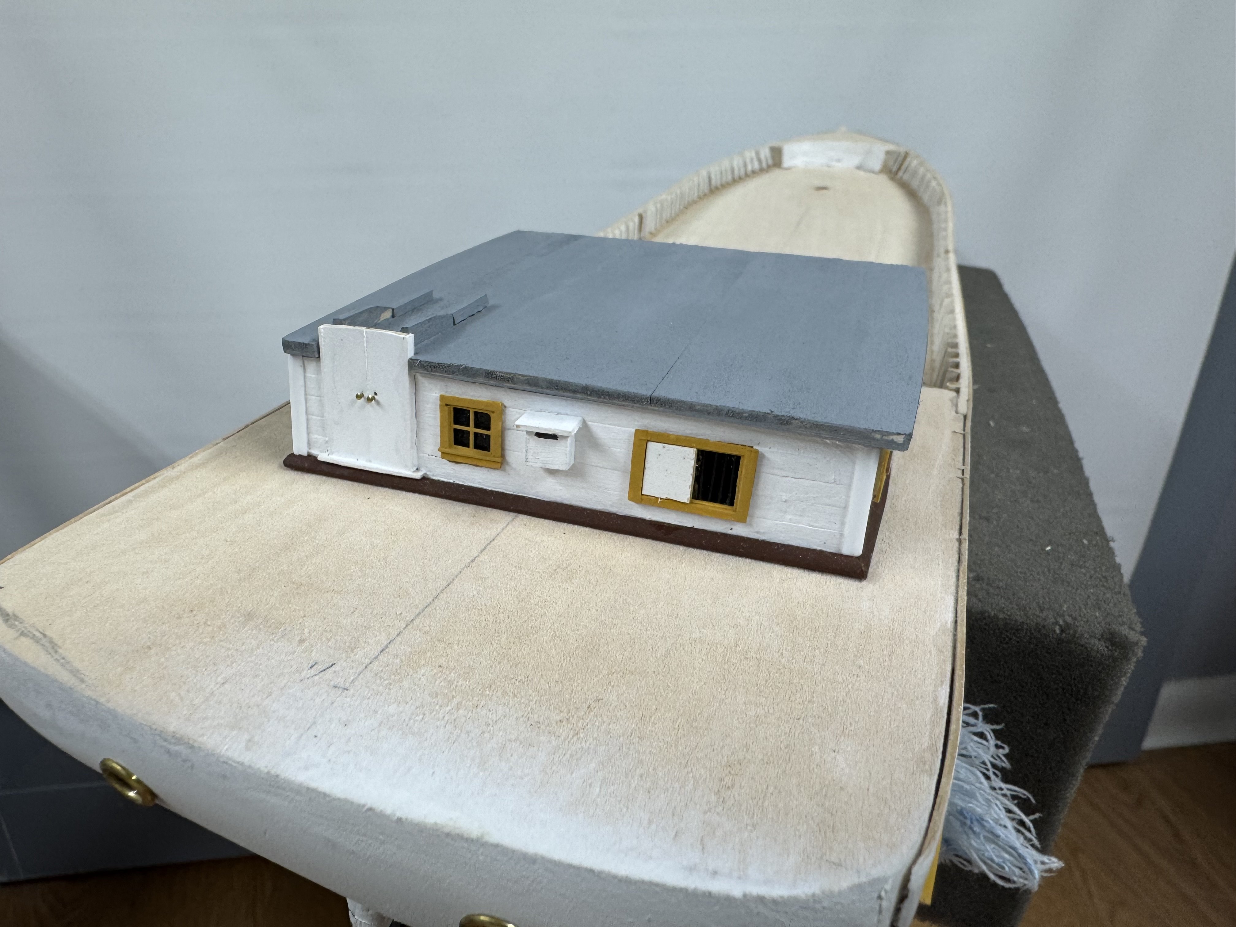
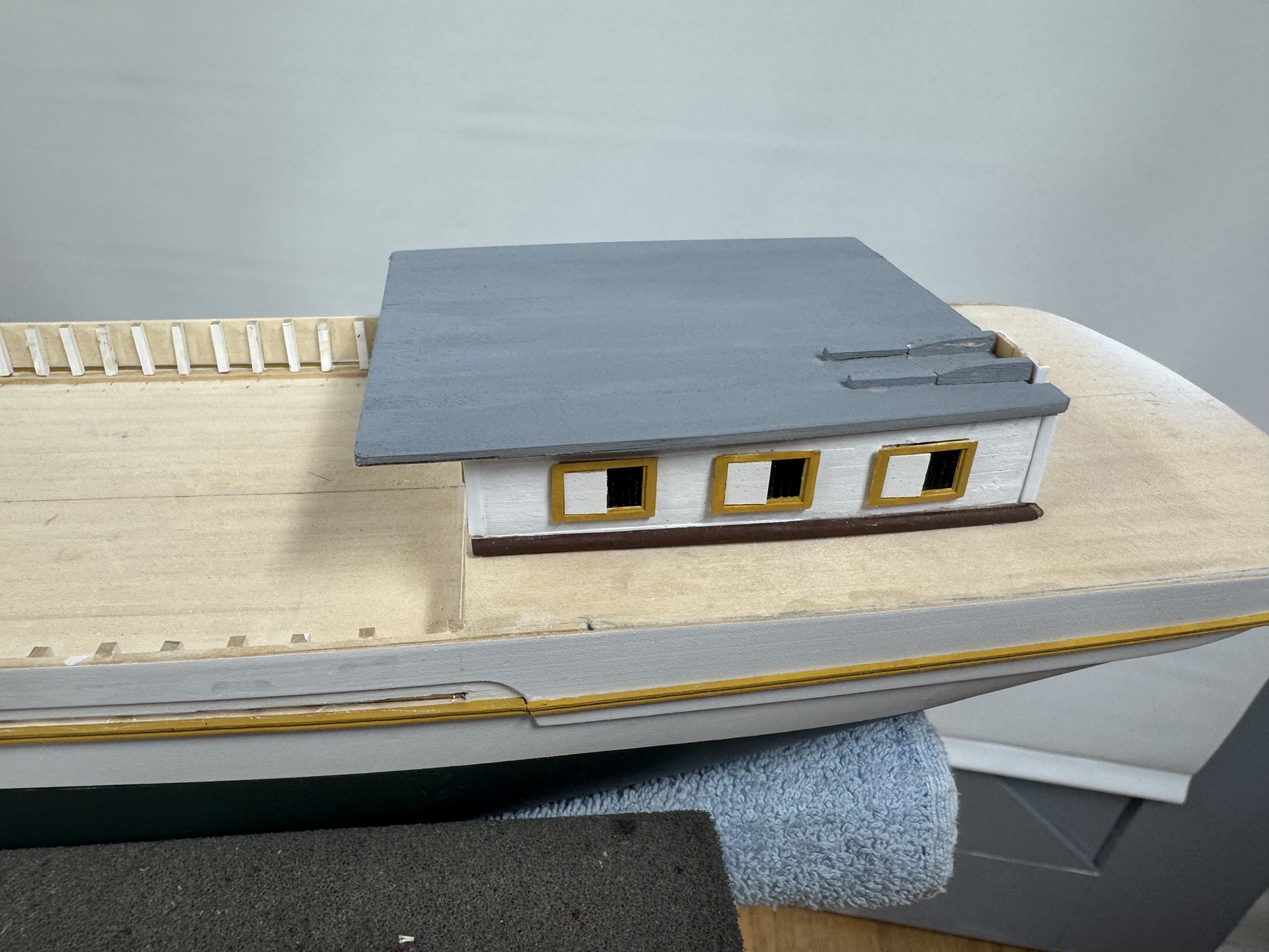
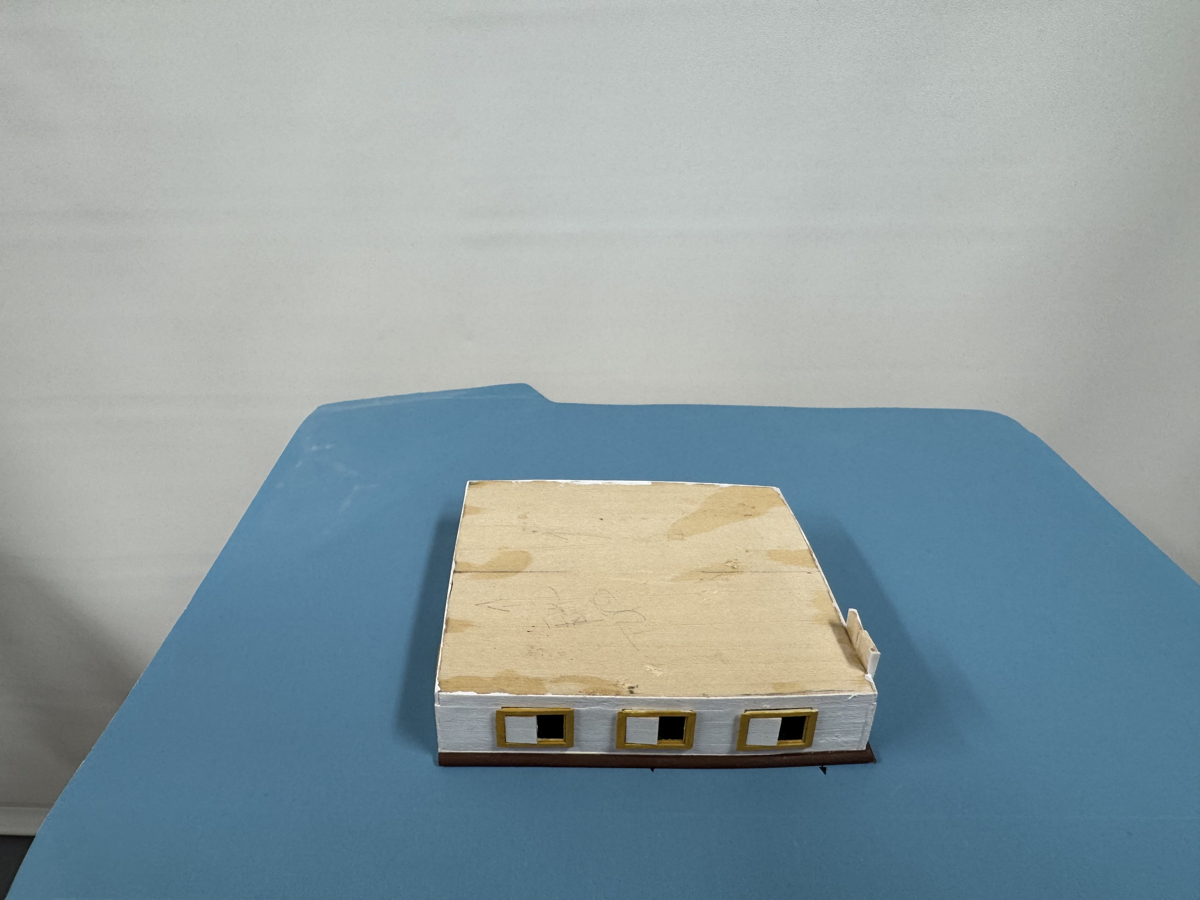
The grey paint arrived today and first up was to paint the deckhouse roof. As seen here it does not yet have the sliding cover in place as there was a minor issue after it was painted. Also of note is I got all the timberhaeds installed and sanded down flush with the bulwark. Next step is to paint the inside bulwark, plank the area below the aft deckhouse leaving an opening where the forward facing door will go when the deckhouse is truly installed. Hatch and smoke stack will also go on during actual deckhouse installation


- 121 replies
-
- 3
-
-
- Lucia A Simpson
- AJ Fisher
- (and 1 more)
-
Considering the rigging to come. I started a spreadsheet of all the standing and running rigging needed and found the rigging drawing somewhat confusing. Yesterday I discovered on sheet 3 (of 3) there is a drawing showing how the throat and peak halyards (one of each on all three masts) are supposed to be rigged. This drawing answered one of the questions I had about the throat halyard (raises the gaff to spread out the fore, main and mizzen sails attached to the respective booms). On the rigging drawing (sheet 2) it shows there is a triple block at the top of the throat halyard tackle. Try as I might I could not figure out how that would work and all of the reference material I have was. no help. From the ships I have built it was common practice to have the "jig" end as referred to in the drawing (I would call this the standing end but...) terminated at a becket on the upper block of a throat halyard. Not so on the Simpson - the jig end and the tackle on the hauling end terminate at the pin rail and thus you need a triple block at the top. Unfortunately I did not have any 4mm triples so I ordered some from Model Expo. I have plenty to do before I need them but I feel much better having solved what was to me a mystery.
-
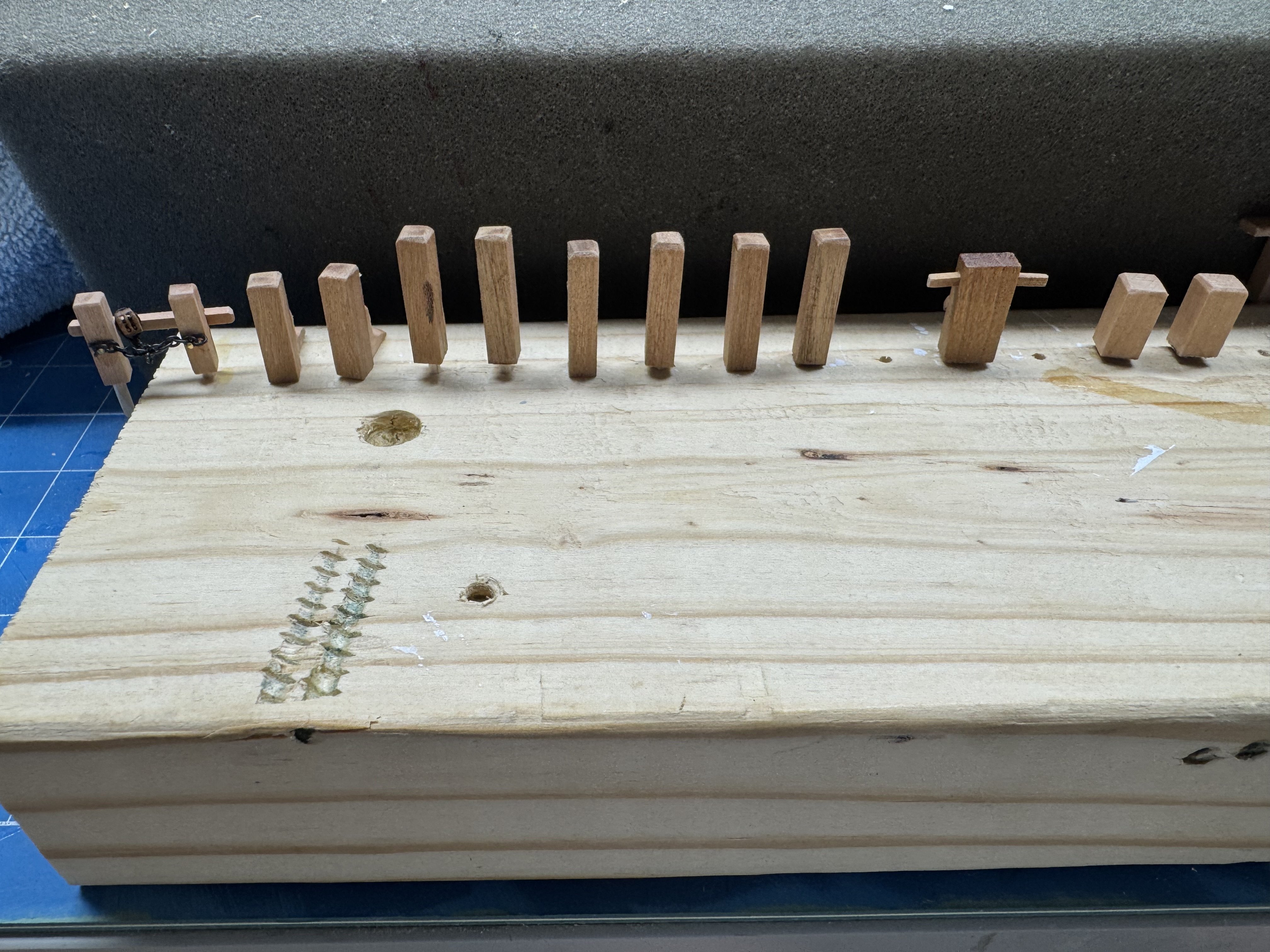
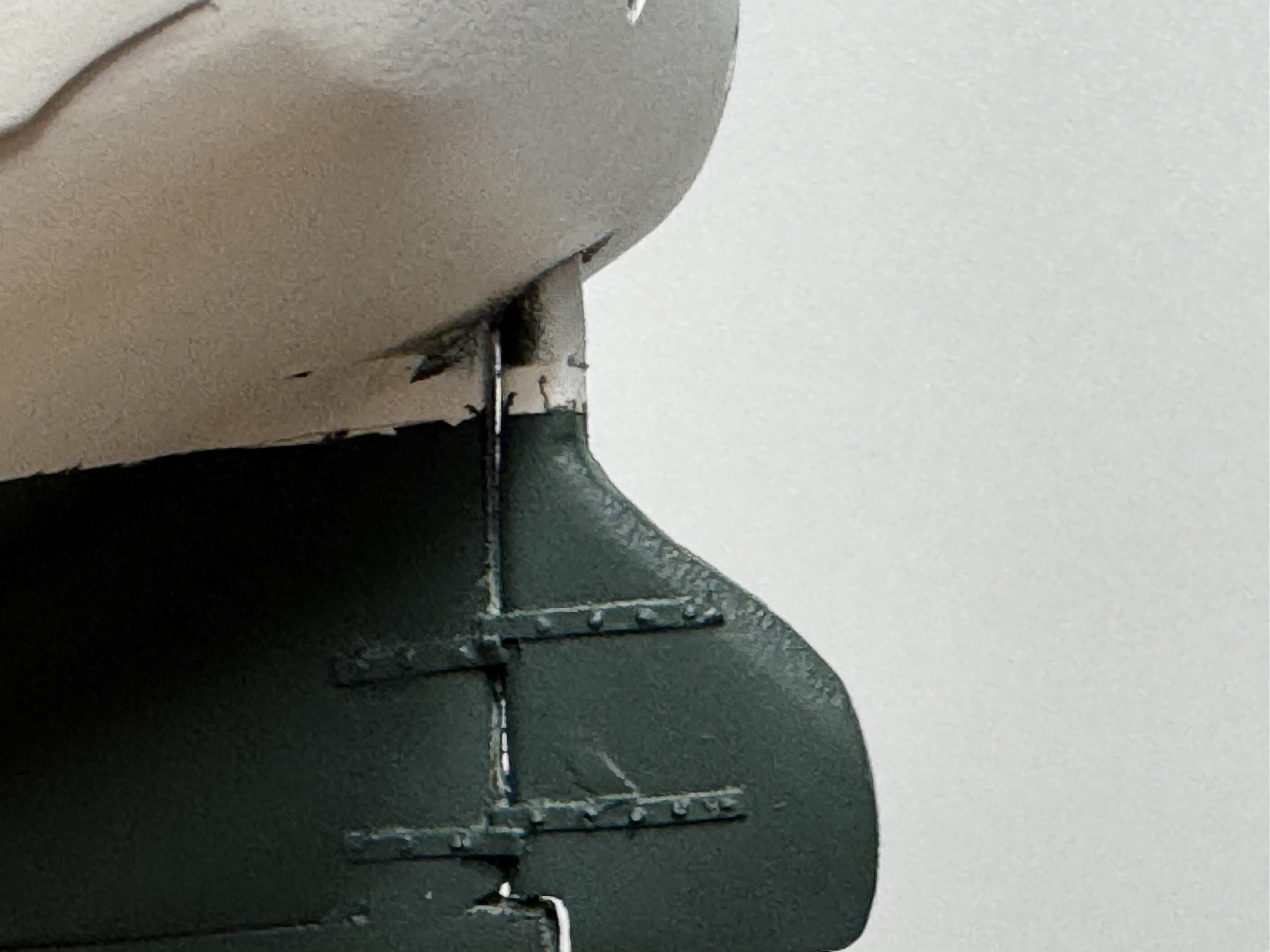
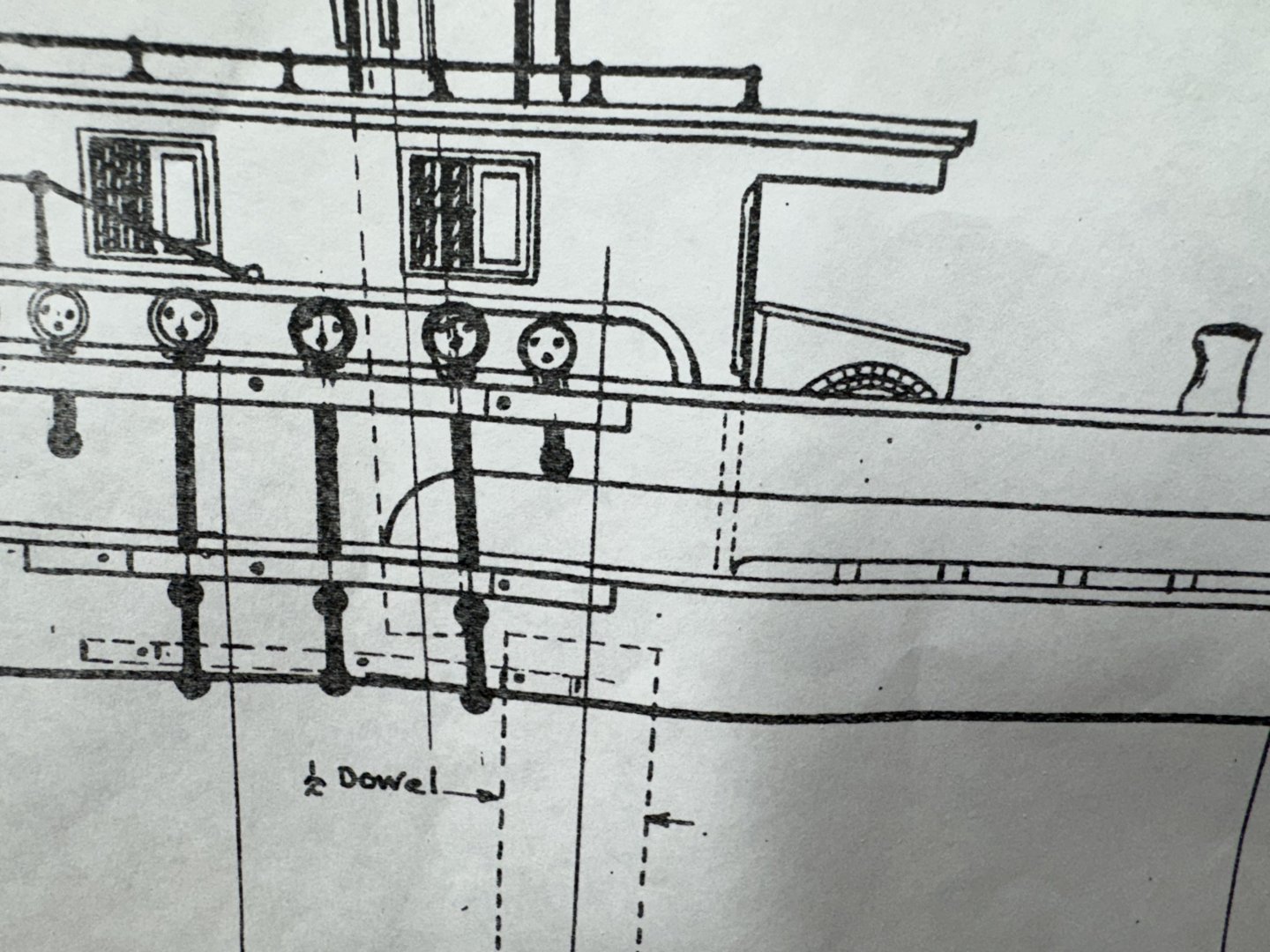
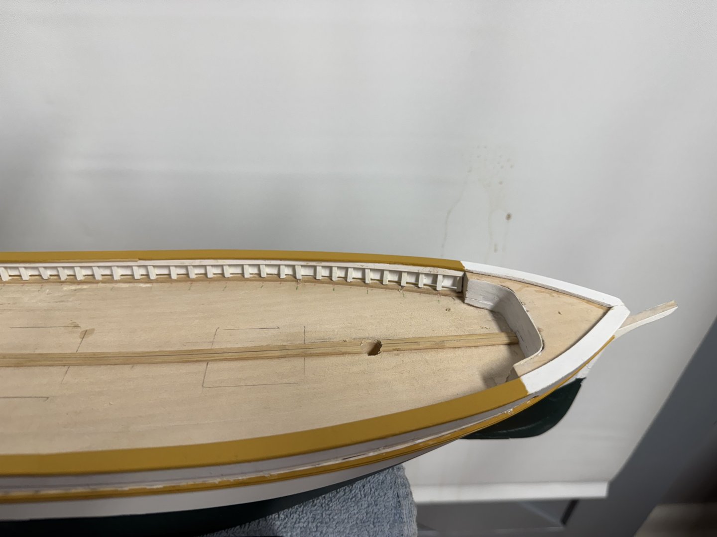
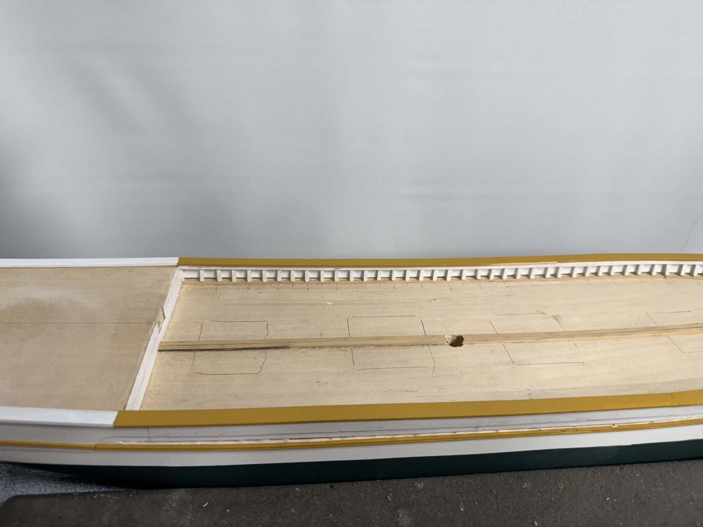
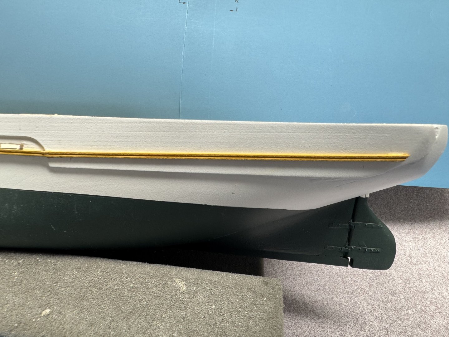
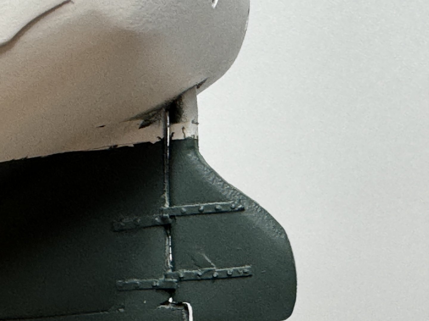
After I looked at it enough I came to the conclusion that having the molding stripe stop at station 8 just was not going to work. So I created another 2mm X 2mm piece of boxwood and ran it through the same molding cutter I used for the first piece. Then I went back to the thickness sander and (making sure I kept the flat side against the sandpaper) thinned the piece down until it was just over 1mm thick. Doing this was to avoid an abrupt change in thickness at the junction. I think this looks much better IMHO. I also fabbed the four towing bitts and six just plain bitts from Swiss Pear. The painting instructions say these should be brown so I think varnished Swiss Pear will be close enough. Here they are after the first coat of matt varnish (from Vallejo). I also used cut off toothpicks for the "posts" The drawing indicates that the square posts would have to be turned to form a round portion for insertion into the deck. I think toothpicks into a hole drilled with a #48 bit is much easier as long as you can get the hole pretty much in the center of the bitt.
- 121 replies
-
- 2
-
-
- Lucia A Simpson
- AJ Fisher
- (and 1 more)
-
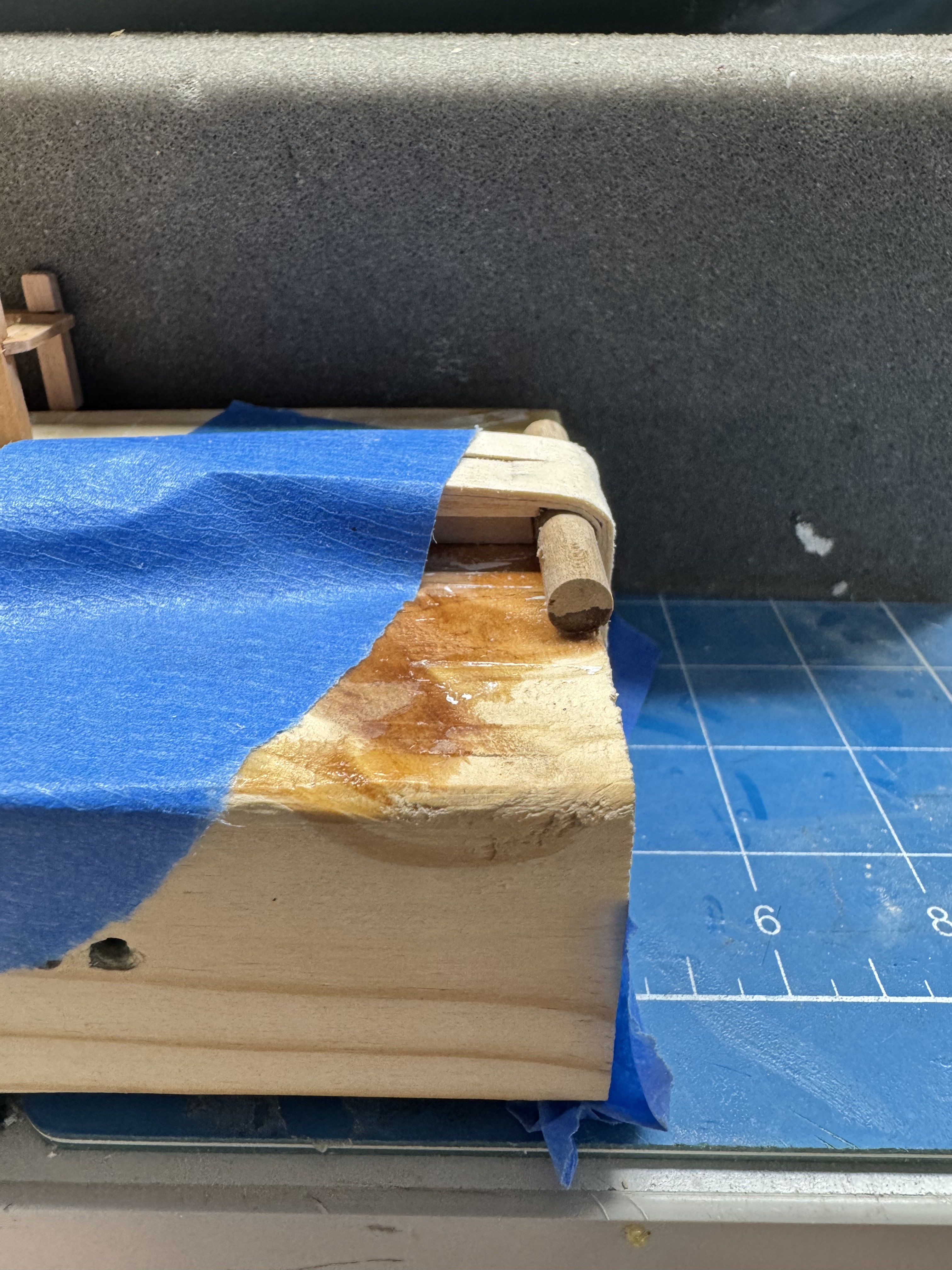
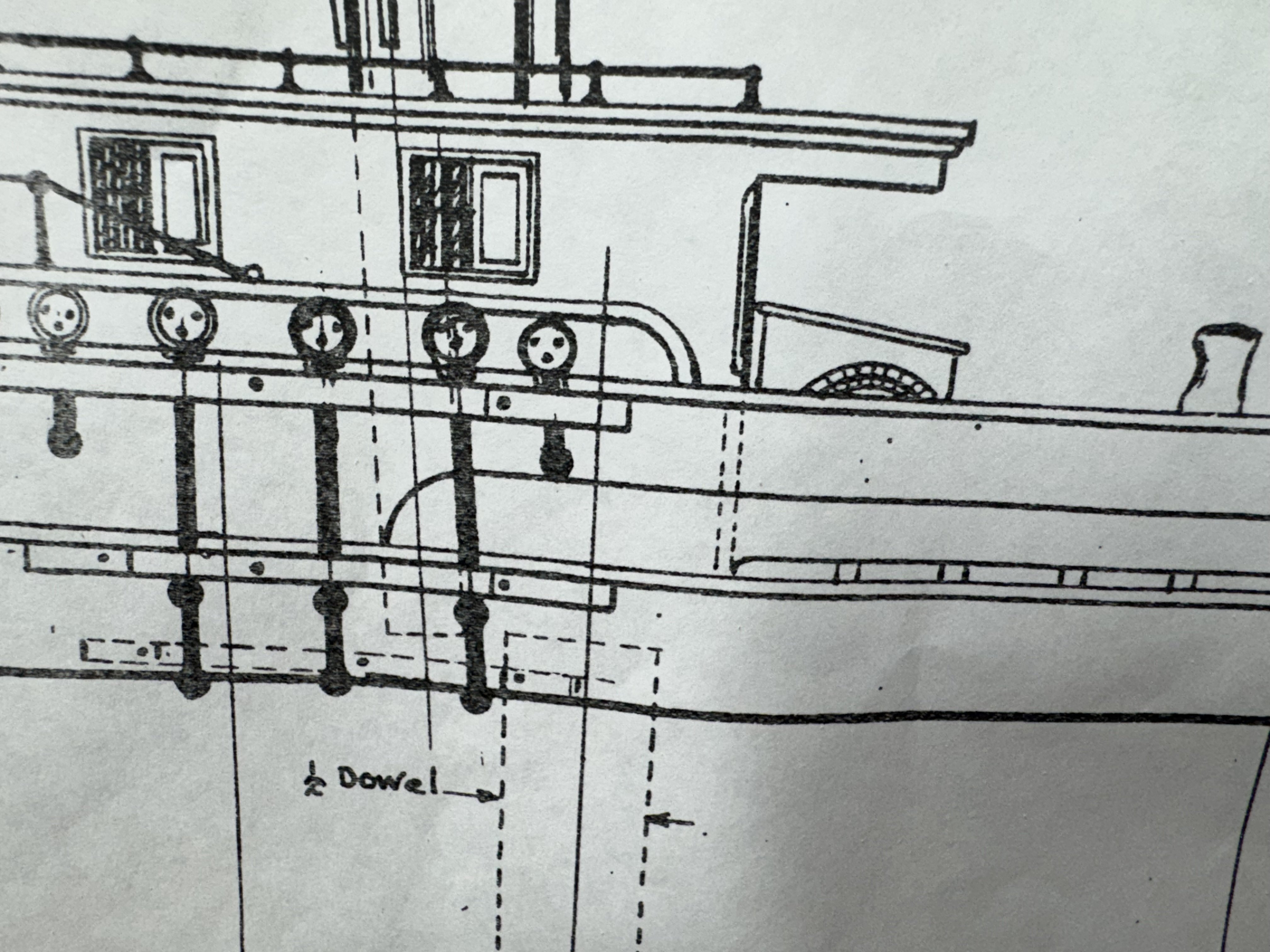
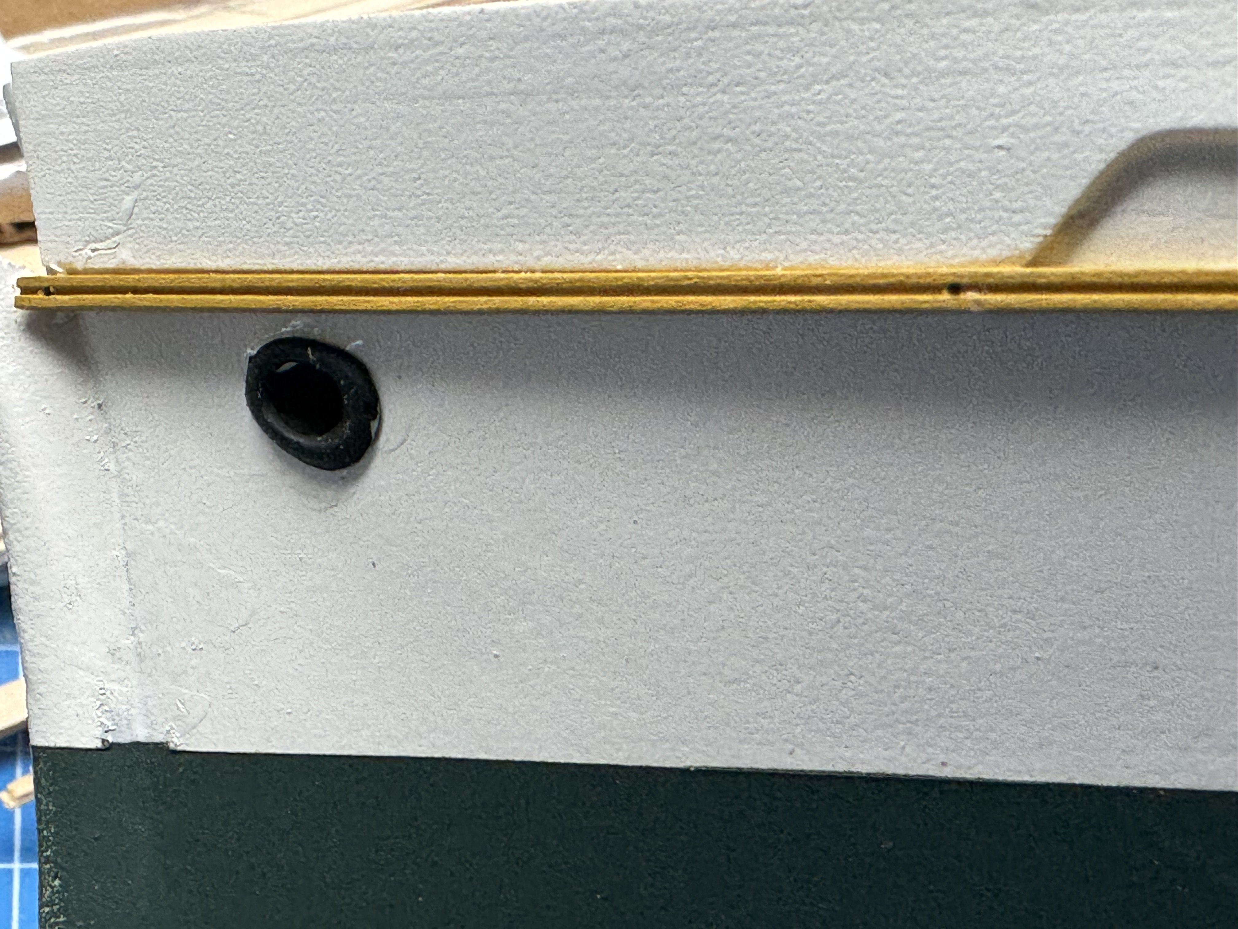
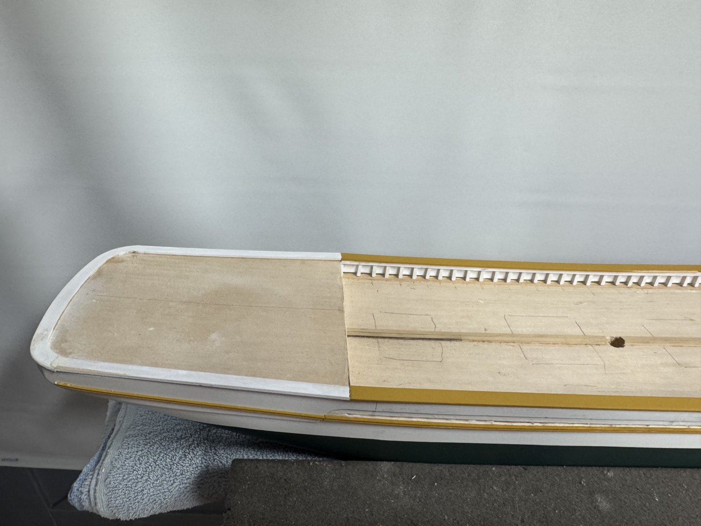
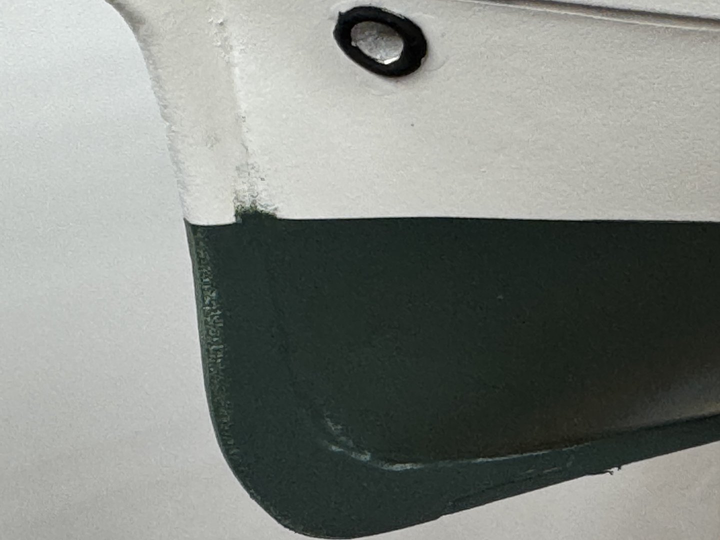
I added the molding stripe to the hull now that the painting is done. The instructions call for a 1/16" X 1/16" strip from bow to station 91/2. I found this less than satisfying. So I created a 2mm X 2mm piece of boxwood and used a molding cutter to form a "U" shape into the wood. I painted it ocre and glue it on but stopped at the overlay stripe at the stern. Had I looked more closely I would have seen that the overlay stripe was not supposed to extend as far down the hull as mine does but IMHO I think this looks "okay". Here is a closer look at the molding stripe The holes were from the pins I used to hold the strip ion place while the glue dried. I think a dot of paint will cover them.I am considering painting the cap rail the same ocre as the molding stripe but that decision is a ways off yet. The paint job does not look all that good this close, so I plan on having this model on the top shelf where it is hard to get really close. I decided to plank the bulwarks that form the forecastle since the machine that milled the hull left these areas pretty "rough". I do not have to do a really good job and chose to use two pieces instead of one since the Sampson post will be at the very front of this area making the joint more or less invisible.

- 121 replies
-
- 3
-
-
- Lucia A Simpson
- AJ Fisher
- (and 1 more)
-
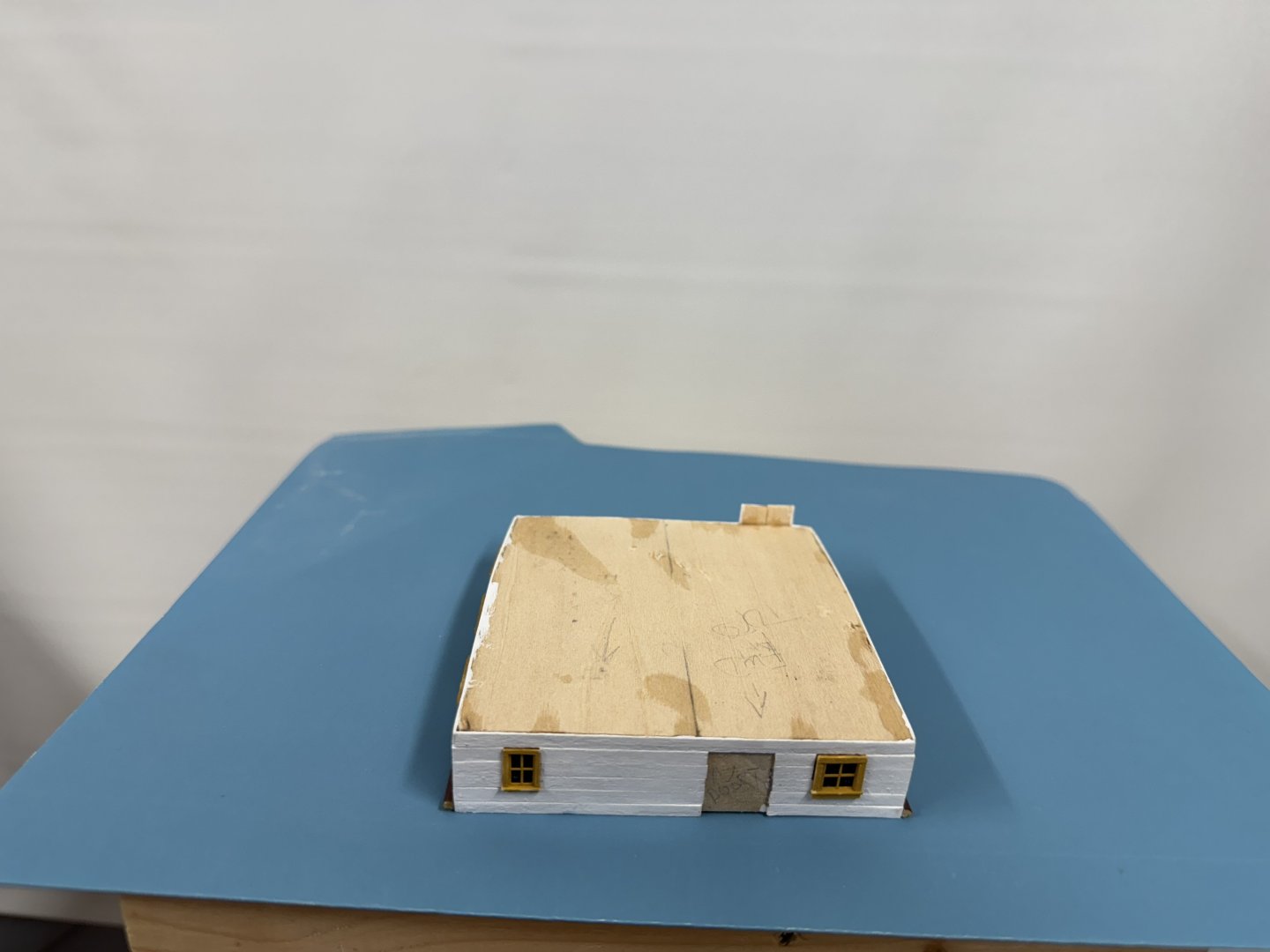
Aft deckhouse is done except for the roof which is awaiting some grey paint due here Wednesday or Thursday. I cropped these to look better but the site refuses to upload the edited version so... Also thew binnacle box needed another coat of paint so it is not yet on the aft side.


- 121 replies
-
- 1
-
-
- Lucia A Simpson
- AJ Fisher
- (and 1 more)
-
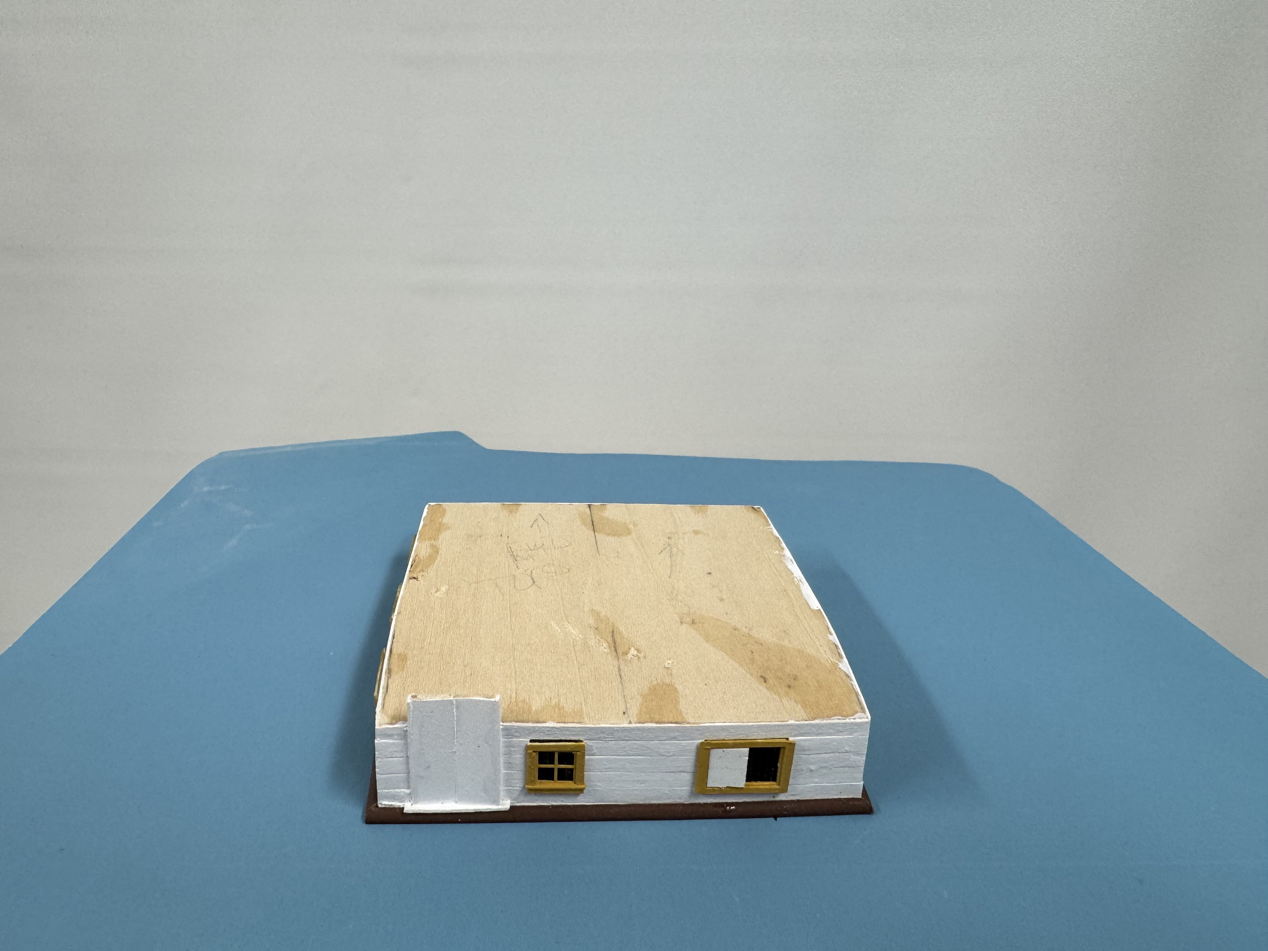
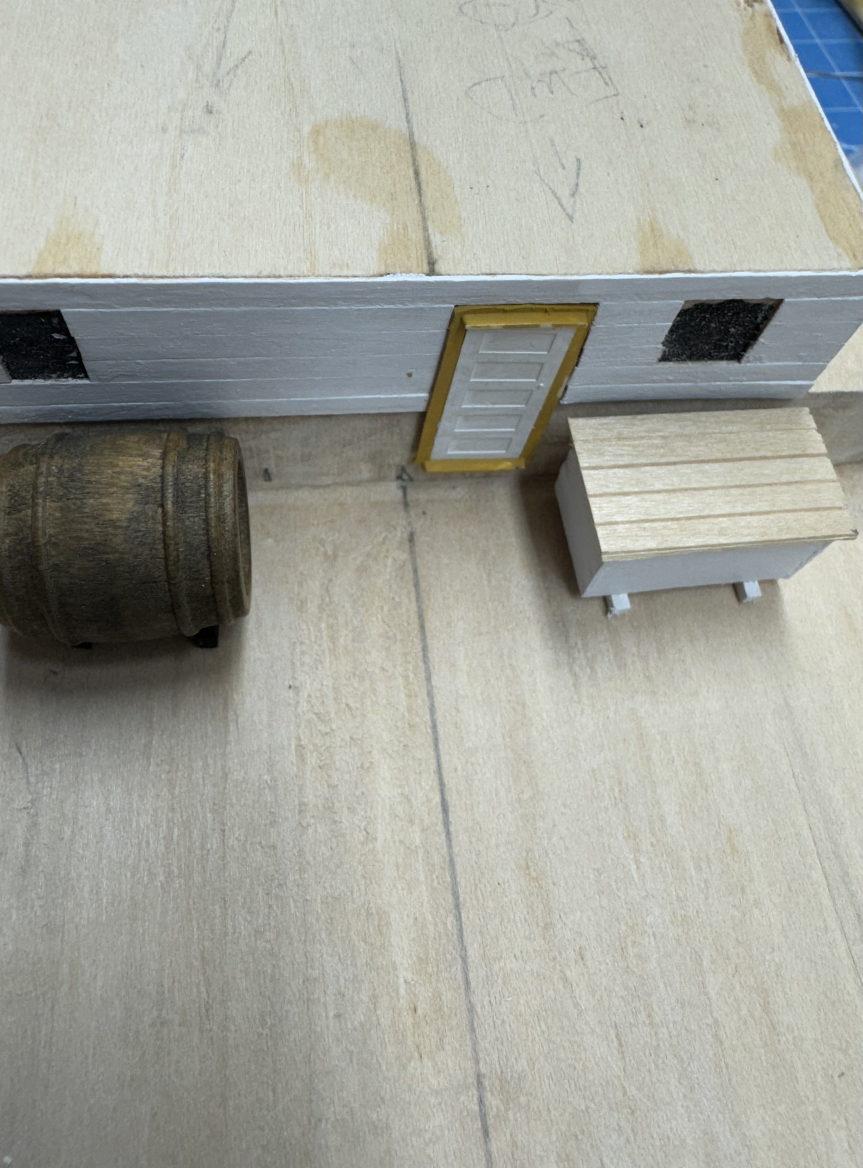
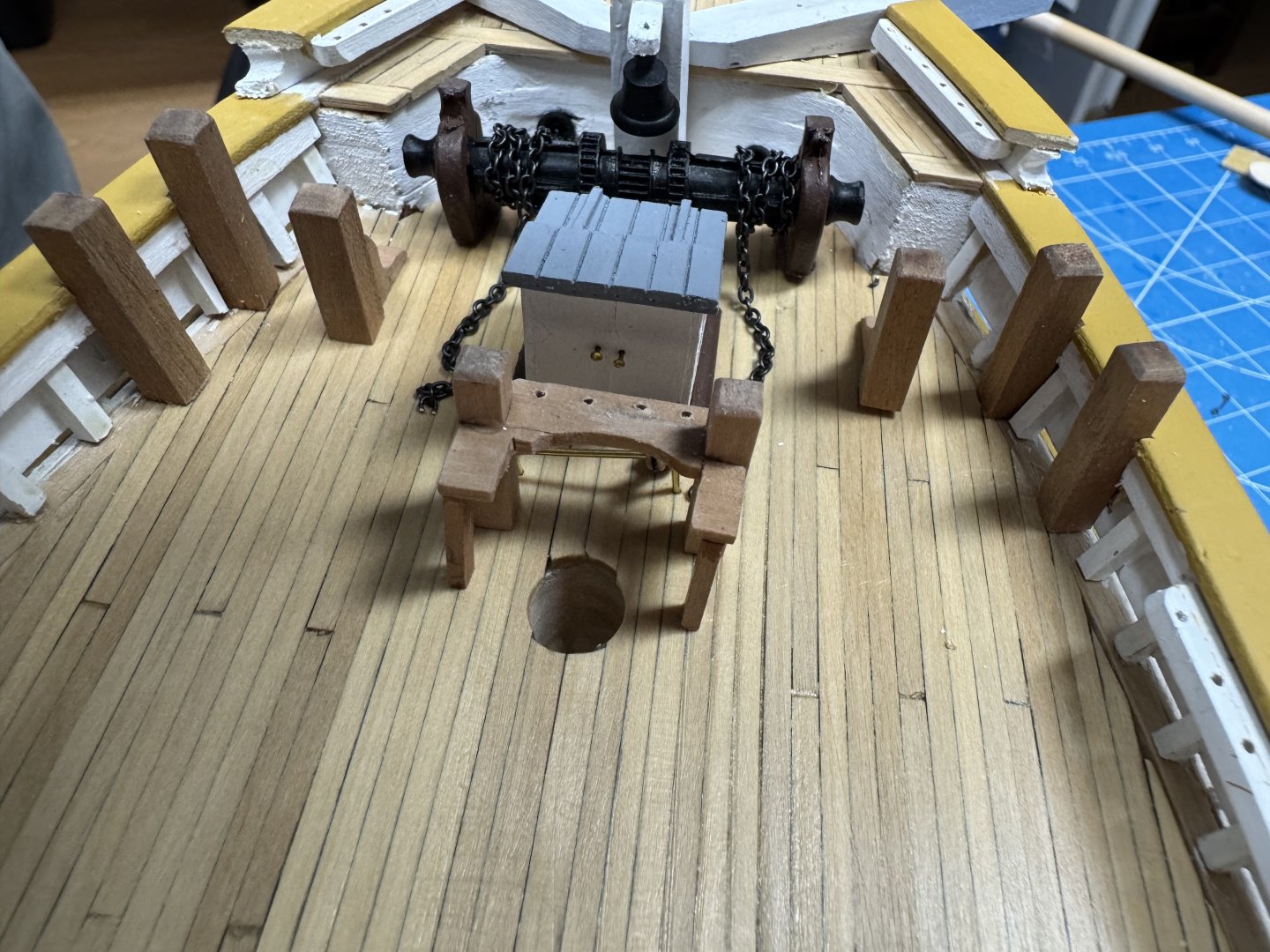
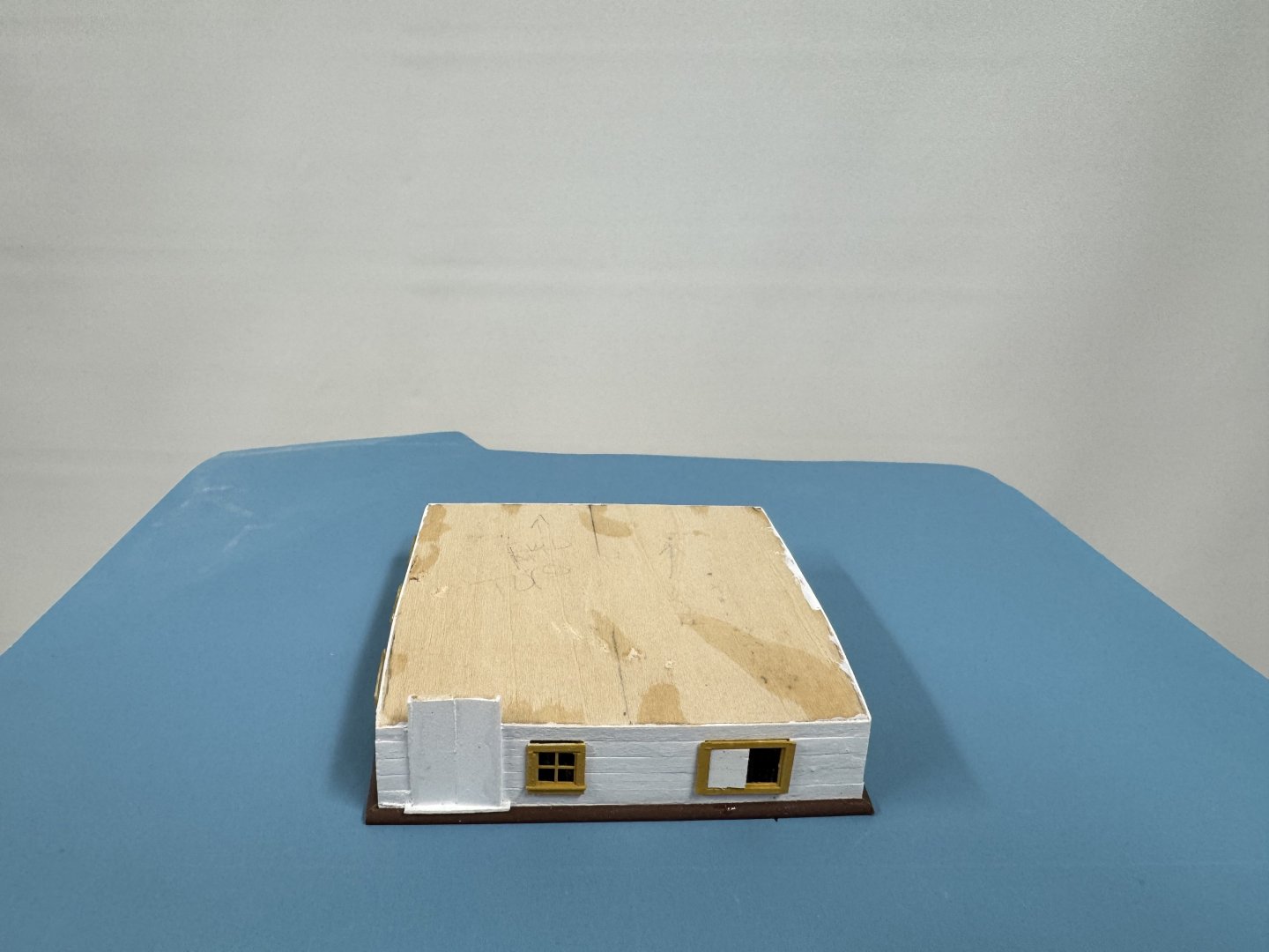
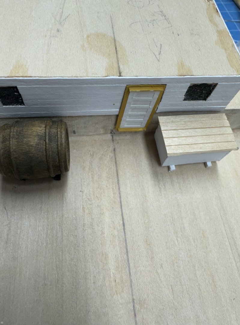
With the hull now ready (still need to clean up the spillover from waterline) and the aft deckhouse almost ready I thought I would try a dry fit to see if everything was going to "work". I fashioned supports for the water barrel and meat box and they seem to work okay. The meat box lid will be painted grey to match the deckhouse roof but the grey paint will. not be here for a few days yet so.... FYI the water barrel is from Caldercraft not the Britannia metal one that came with the kit. It is a little larger than the kit supplied but not really out of scale IMHO. And yes I see that the door is a little "off".
- 121 replies
-
- 2
-
-
- Lucia A Simpson
- AJ Fisher
- (and 1 more)
-
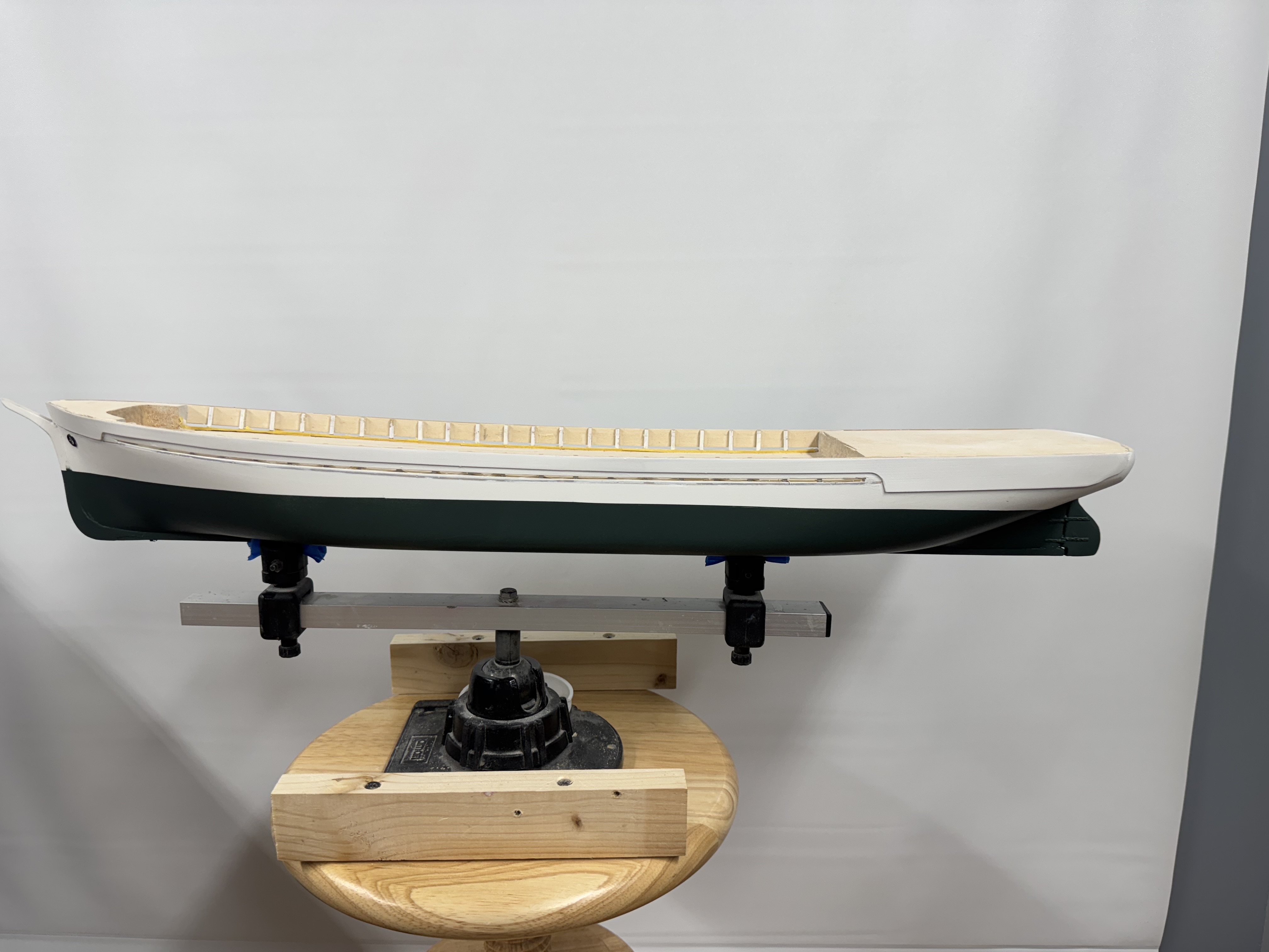
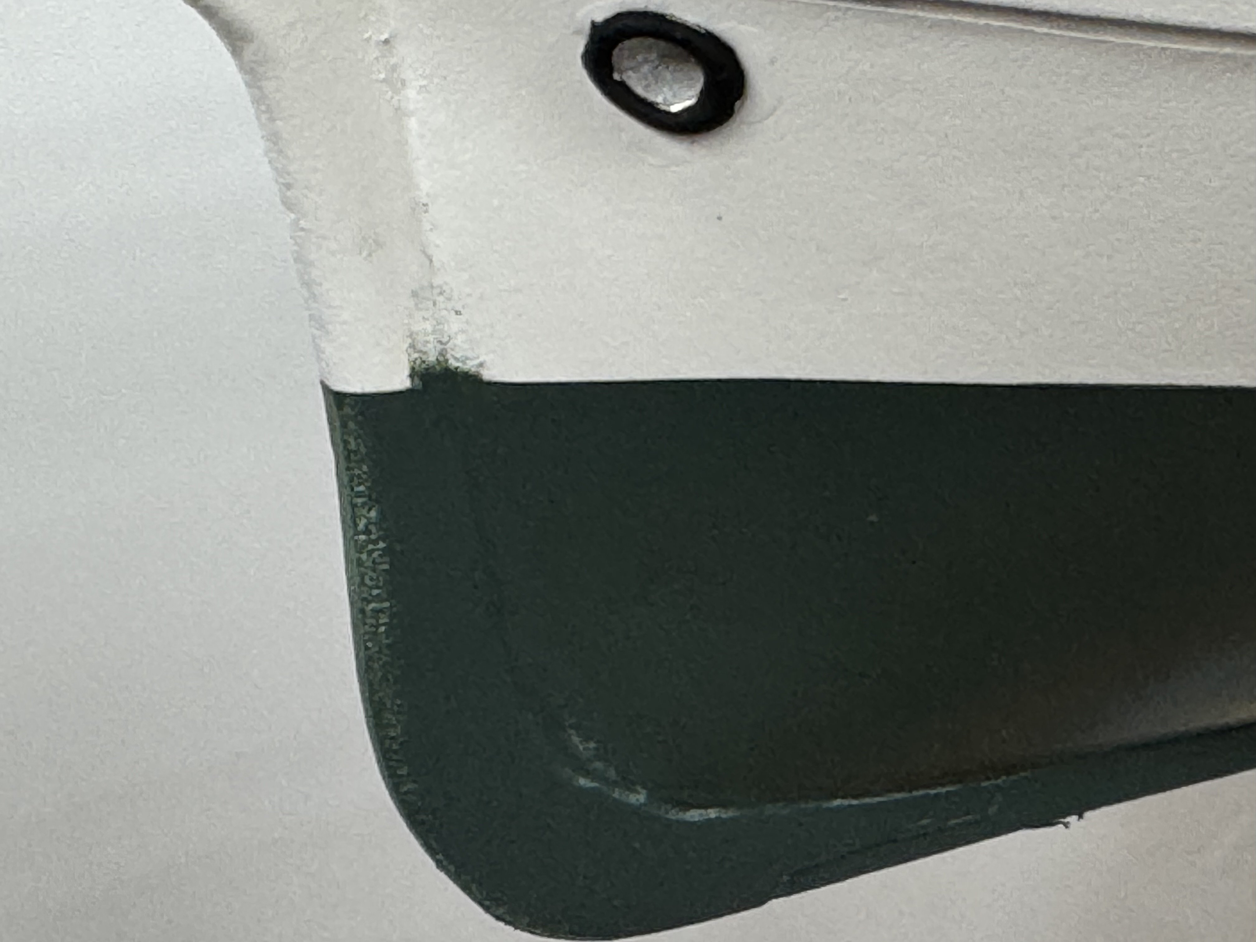
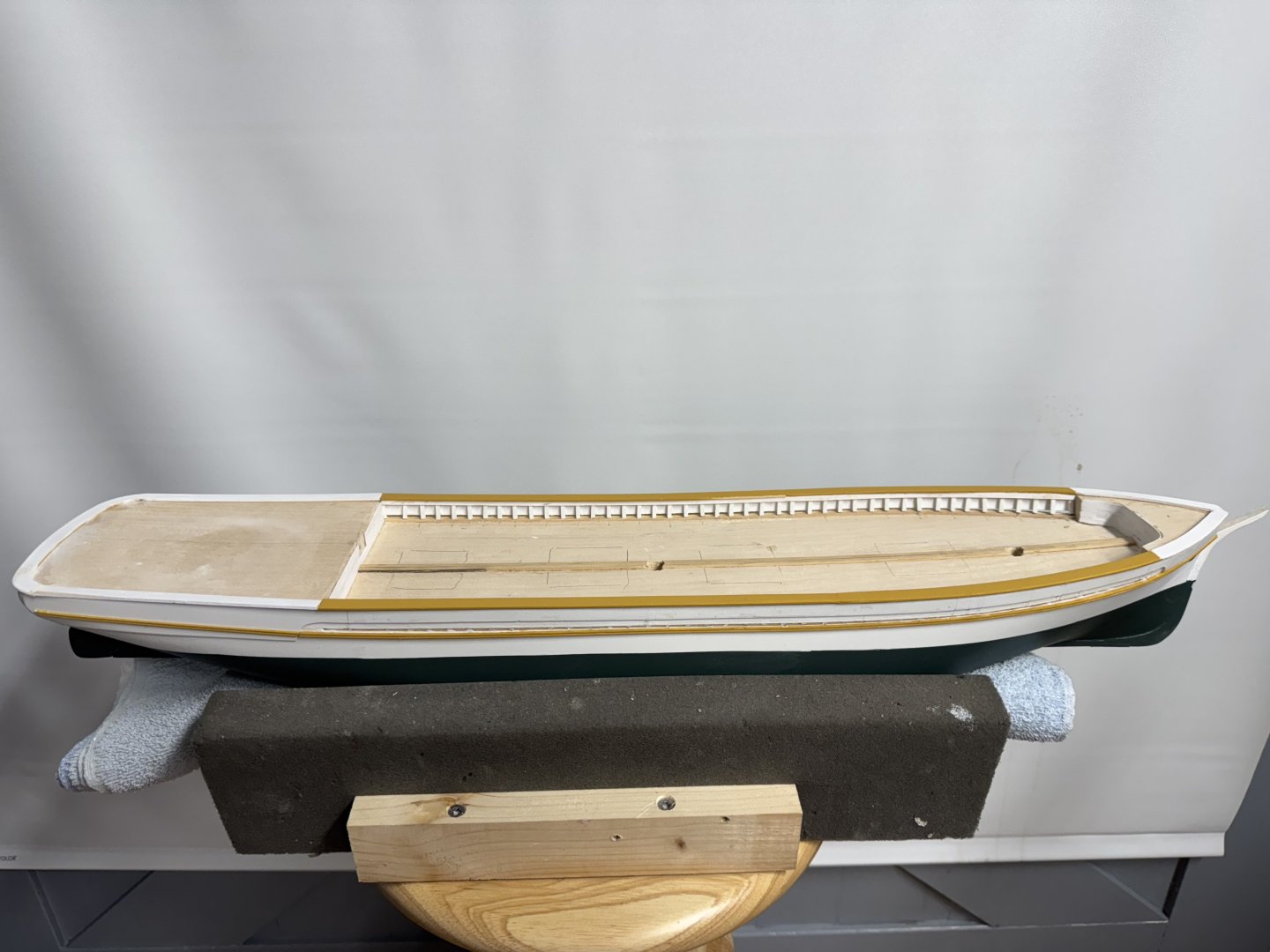
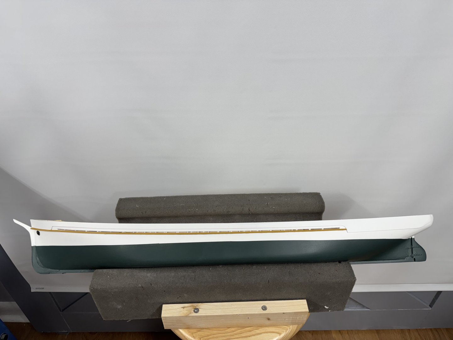
Hull is out of the paint booth and looks pretty good. The green color is a little darker than I had thought but since you can only judge color by the cap on the can (at Walmart) I guess it will "do". Not the "Kelarney green" from the instructions but I am not sure what shade of green that is anyway. There are a few areas of touch up but since it is green on white I have the correct color of white to patch things up. If I had to add more green I would have to deal with spraying into a cup or similar container than then dipping a brush in the container. not very elegant and can be really messy. I got a nice sharp waterline using Tamiya masking tape and then painting over the junction between the tape and the white with flat clear acrylic. I was told it helps seal the joint to reduce the chance of paint seeping by. It appears to have worked this time. Working on the deck furniture and making a spreadsheet of all the blocks/deadeyes that need to be made up. Sometime to keep me occupied for more than a few days to come.

- 121 replies
-
- 4
-
-
- Lucia A Simpson
- AJ Fisher
- (and 1 more)