HOLIDAY DONATION DRIVE - SUPPORT MSW - DO YOUR PART TO KEEP THIS GREAT FORUM GOING! (Only 24 donations so far out of 49,000 members - C'mon guys!)
×


cdrusn89
-
Posts
1,915 -
Joined
-
Last visited
Content Type
Profiles
Forums
Gallery
Events
Everything posted by cdrusn89
-
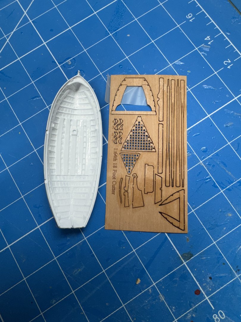
 Hull is back in the paint booth so I decided to detail the lifeboat. I got the outside painted during the hull's late paint booth tour. As I mentioned before this is the 1/64th scale 18' cutter from Vanguard which is an almost exact match at least in length with what is shown on the Simpson drawings as the "lifeboat". Here is the more or less completed lifeboat positioned on one of the pages in the vanguard online instructions. I am going to add an ocre strip at the top of the gunnels on the outside as the white spra paint failed to cover that very well and the boat needs a bit of color. The boat kit includes four oars but they are so tender I am afraid to do anything with them but maybe paint and even that might be a struggle. I did find a set of brass oars (Amati) which are the exact size so I will use them once i get them cleaned and painted. Probably no more than four as there are only four openings in the gunnel for oars. And I am reluctant to believe that the Simpson carried the boat in the stern davits with the rudder "hanging in the breeze". Rudders are to critical to operating the boat to risk it being carried away or damaged by a rouge wave. I am going to paint the lower portion of the rudder white but leave it in the boat once it is in the davits.
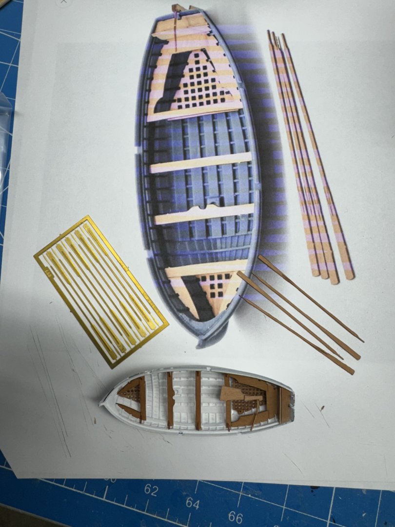
- 121 replies
-
- 3
-

-
- Lucia A Simpson
- AJ Fisher
- (and 1 more)
-
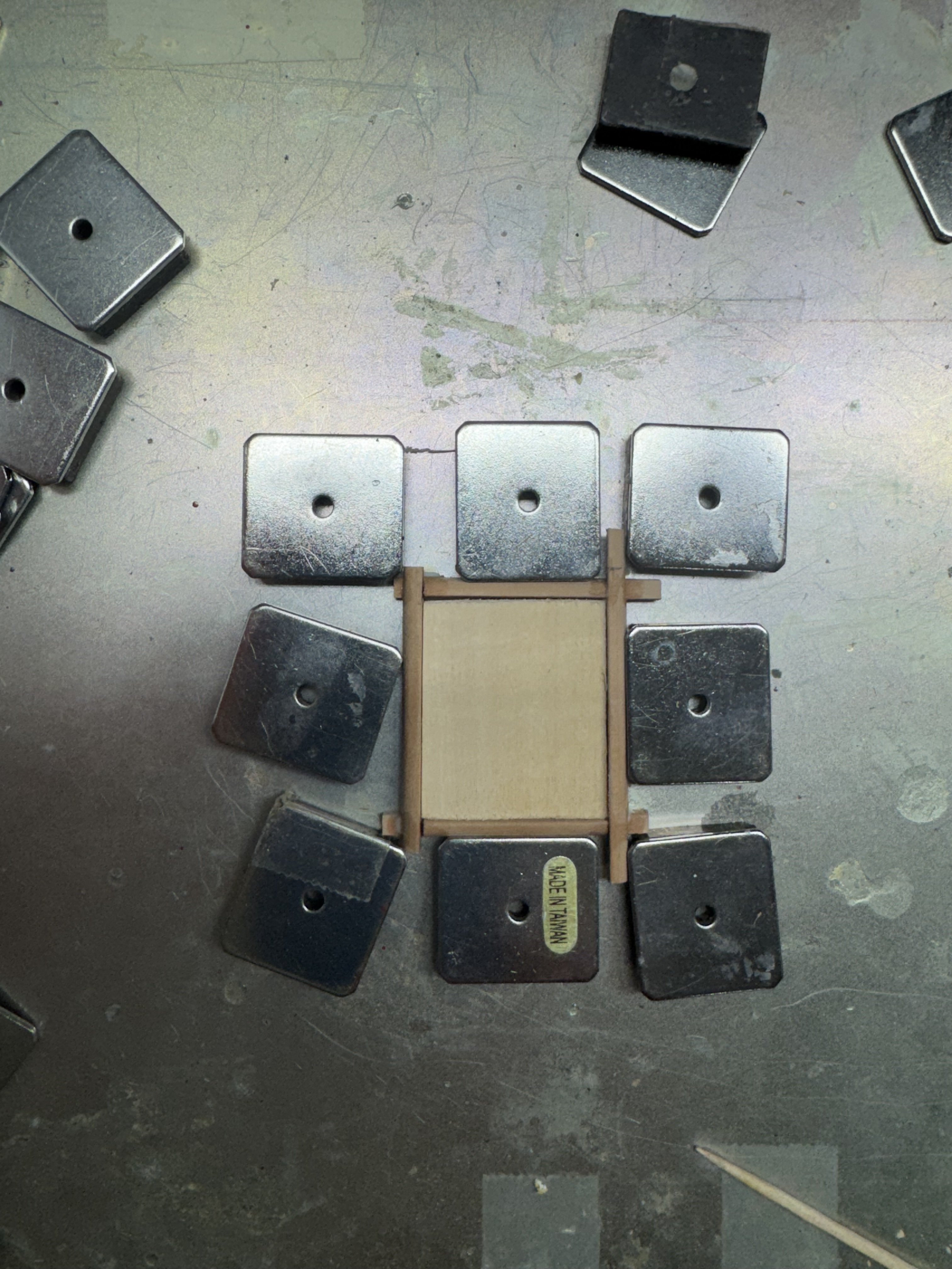
While waiting for the (hopefully) last little bit of filler to dry on the hull I started on the hatch coamings. The drawing shows a total of 7/32" height for the coaming which implies a 1/32" "topper" on the rectangular blank provided which is 3/16" thick. I have a bunch of Swiss Pear that has been looking for a home so I ripped come pieces to 7/32" and ran them through the molding cutter to get the top 3mm rounded off. The plan is to paint the hatch coamings brown along with the deck level moldings around the deckhouse so the choice of wood is more or less whatever is handy and easy to run through a molding cutter. My first inclination was to miter the corners but before resorting to that I thought I would try a somewhat more elegant and I am lead to believe more historically correct construction method where the corners are joined vertically rather than horizontally. Here is the "small hatch" with the coaming drying in my "deck furniture assembly shed.

- 121 replies
-
- 4
-
-
- Lucia A Simpson
- AJ Fisher
- (and 1 more)
-
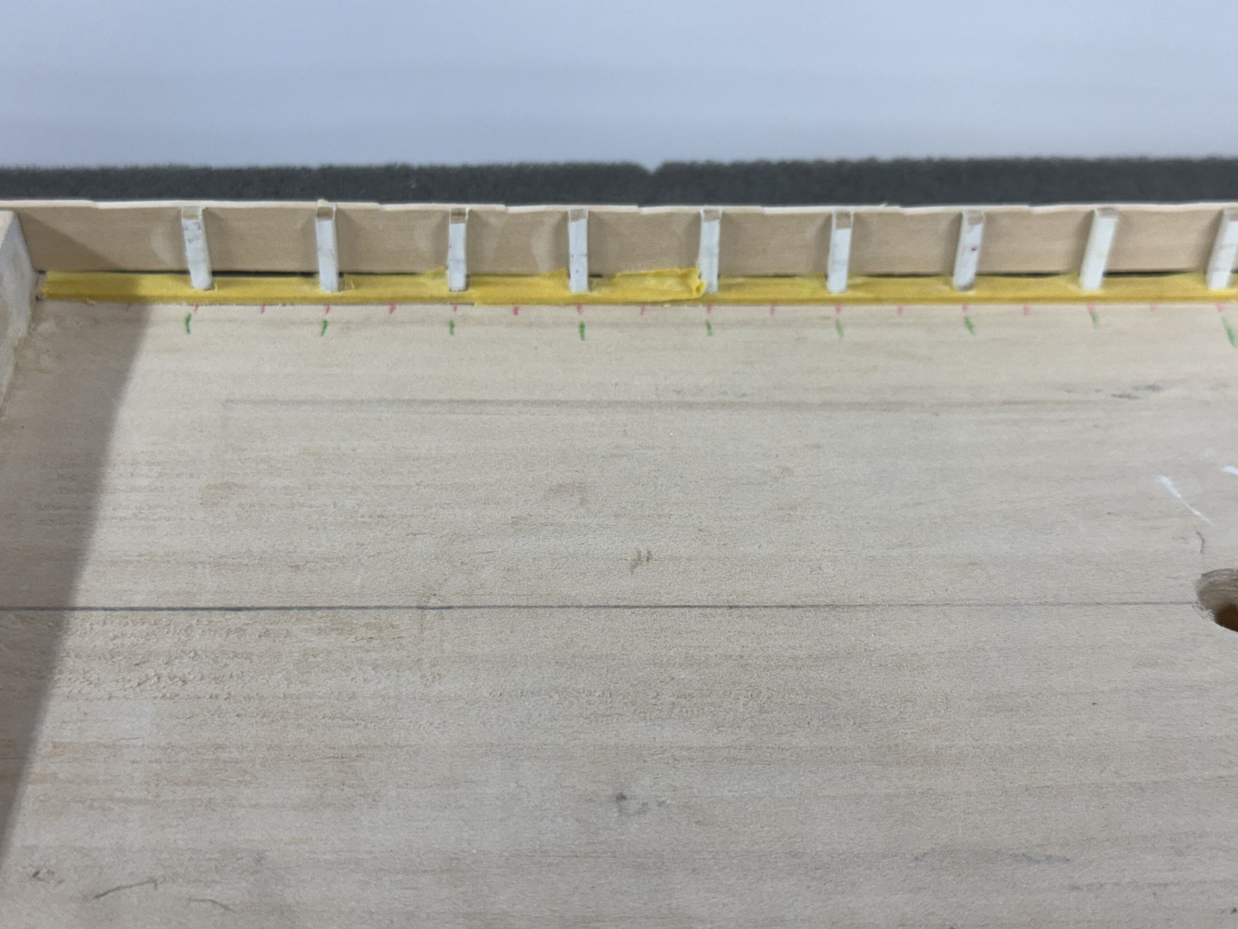
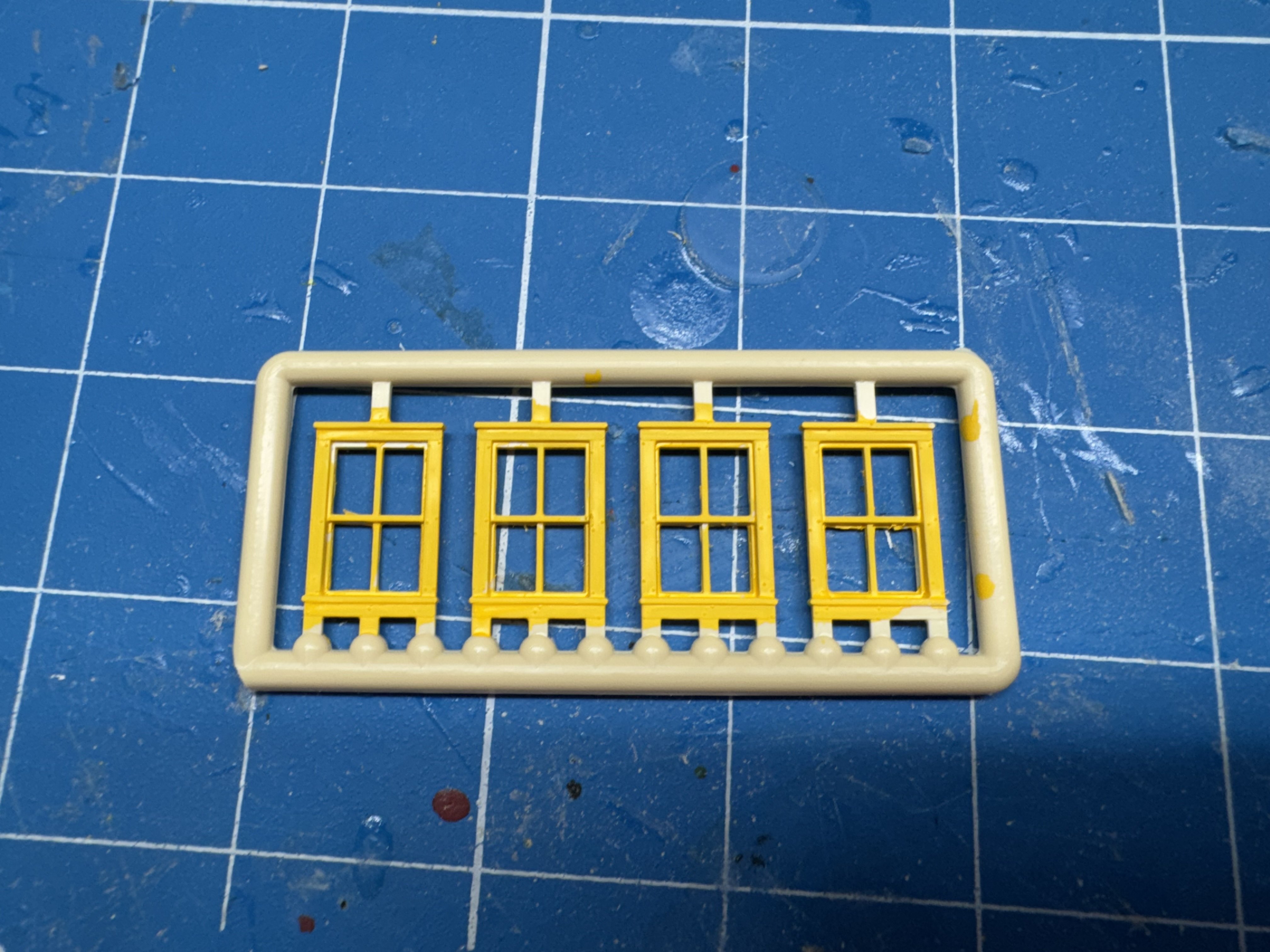
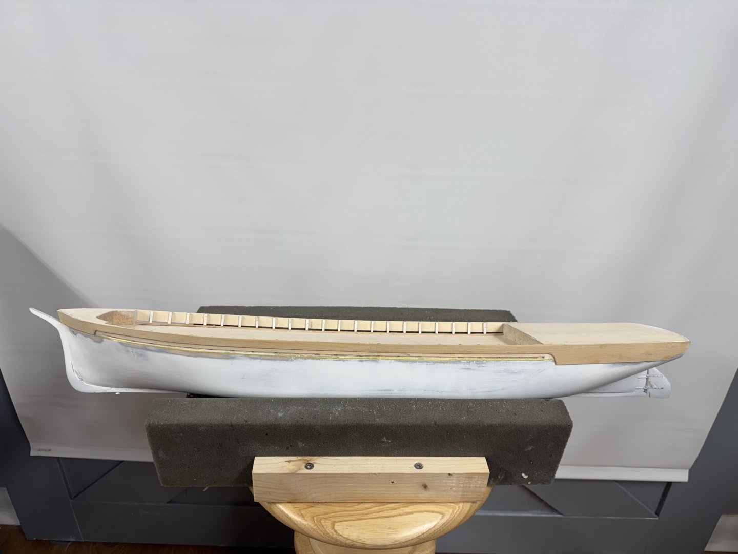
Thanks Pete - that is one fine looking Eagle. I added the "thick overlay strip" to the port side which completes the work on this side before a return to the paint booth to get the white sides "done" (again). The yellow strip you can barely see below the scuppers is 1mm masking tape to provide a landing point for the "molding strip" which runs under the scuppers. My plan is to add this after the hull is completely painted as it will be in ocre instead of white. Hopefully this will add a bit of color to the sides which would otherwise be all white. I will add the additional timberheads and paint the interior of the bulwarks after the hull is completely painted. I looked at the windows that I have mounted on the aft deckhouse and decided two things. First that the sunflower yellow I used on the window frames is too bright - They will be ocre when the new windows (and a larger selection of them) come in from Northeastern Scale Lumber in a few (hopefully) days. Second that the deckhouse is not actually rectangular, that is just the way it comes in the kit. So after removing the existing windows I cut out the roof pattern then reduced that to what I believe are the deckhouse outline and then marked the rectangular block and used the disc sander to round the after third or so to match the plan. It is not all that obvious but the deckhouse tapers toward to bottom. I also decided that the plain flat roof (one solid piece 1/16" thick) provided in the kit was not really how the roof would look. I got some 3/16" pre-scored decking from Northeastern Scale Lumber (I love that place). It is 1/32" thick so I replaced the kit roof with a sandwich of 1/32" basswood and the pre-scored decking. I have to keep in under weight as it wants to curl up some. It will. not be a problem (I hope) once it is glued down to the deckhouse but... It will be painted with a gray wash to preserve the plank delineations. Now on to the starboard side "thick overlay strip" and then the paint booth will not be far behind.

- 121 replies
-
- 4
-
-
- Lucia A Simpson
- AJ Fisher
- (and 1 more)
-
Thanks Rick! Very nice looking Eagle there Peter. Probably harder to break them off since they are not thinned down by being "doweled". If I might ask; how tall are the hatch coamings on your model and what scale? The ones provided on Simpson are 12" tall at full size. As it turns out there is a covering board 1/32" thick outboard of the bulwarks covering the entire side a bit above the scuppers and, as it turns out the junction between the bulwark plank and the solid hull quarterdeck and forecastle so no real sanding and filling required. I did consider planking the bulwarks but since I chickened out planking the solid hull I did not want to draw attention to the lack of hull planking by planking the bulwarks.
-
In preparation for adding (actually re-adding but that story has been told already) the timberheads to the Starboard side I decided it prudent to trim the port side timberheads to a first approximation of their final length. Although they are glued to the bulwark I thought it wise not to tempt faith by having a convenient place for something to catch. I also adding masking tape to protect the "waterway" plank from overspray when I spray the final coat(s) of white on the hull. It will also provide some protection while the inside of the bulwark (and any timberheads needing touch-up) are painted before the deck is laid and after the hull is finished with the spray booth. I still need to find a flat green spray paint for the underwater hull - Walmart should have something since my local hobby shop (mostly model train "stuff") does not carry much in the way of canned spray paint. With the port side more or less protected from mishap I drilled the starboard side holes and glued in the timberheads. At the end I decided to drill all the holes to 5/64" since after the first two timberhead dowels were to large to fit smoothly in the 1/16" hole I thought they would mostly all be too big and a snug fit makes it easier to break off while trying to remove to add glue . (Don't ask me how I know this). Here is the starboard side ready to dry fit the bulwark when the timberheads are dry.

- 121 replies
-
- 4
-
-
- Lucia A Simpson
- AJ Fisher
- (and 1 more)
-
This is the vanguard 1/64 scale 18' Cutter 3D printed hull and associated "inerds" (after two coats of WoP). I painted the entire hull with a gray primer then several coats of Vallejo Flat White on the inside. The outside is still gray but will be sprayed white when I do the final white coat(s) on the hull. It was not cheap but beat the devil out of trying to fashion one from a solid wood block (not supplied) as the kit instructions suggest.
- 121 replies
-
- 3
-
-
- Lucia A Simpson
- AJ Fisher
- (and 1 more)
-
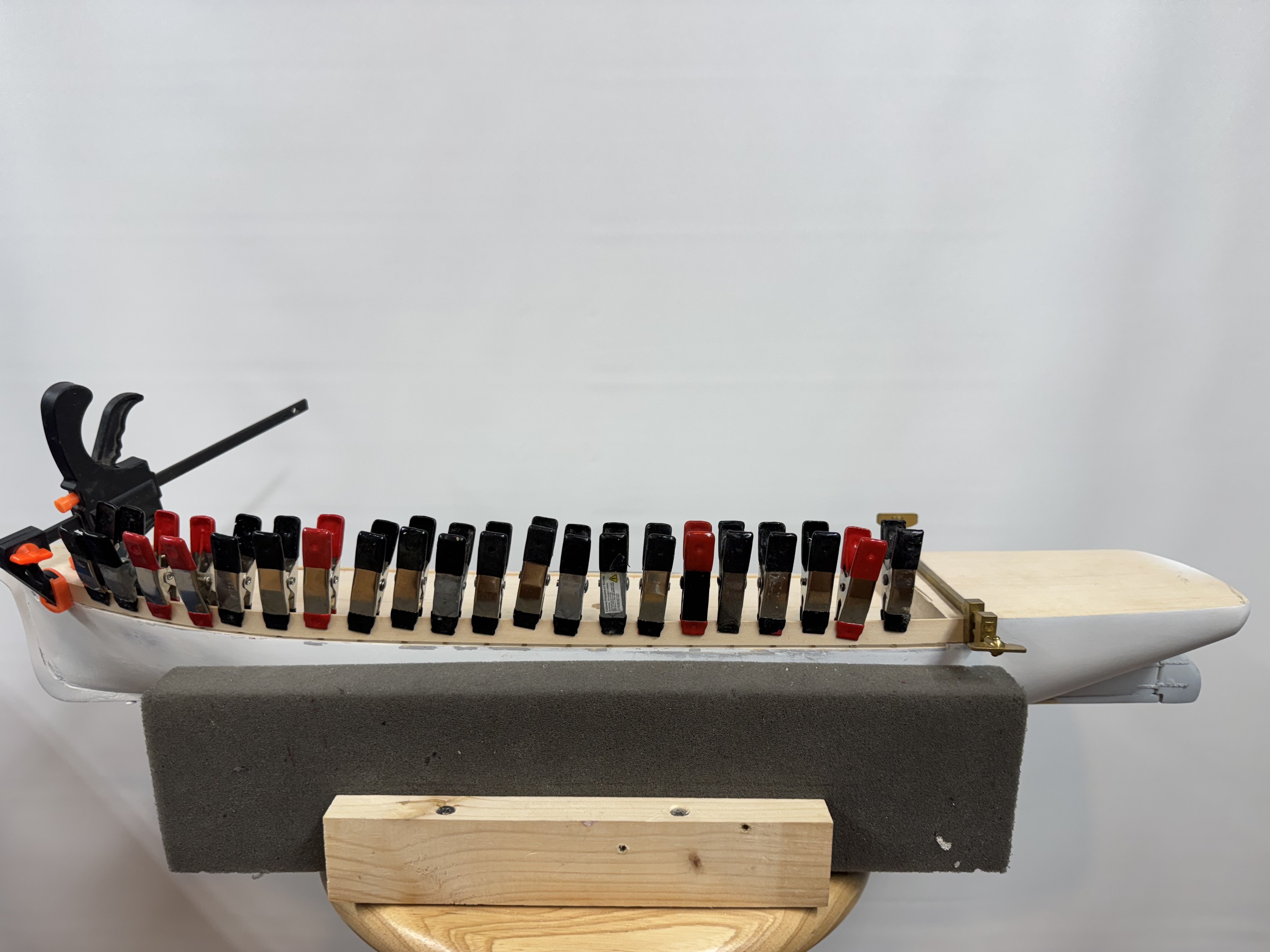
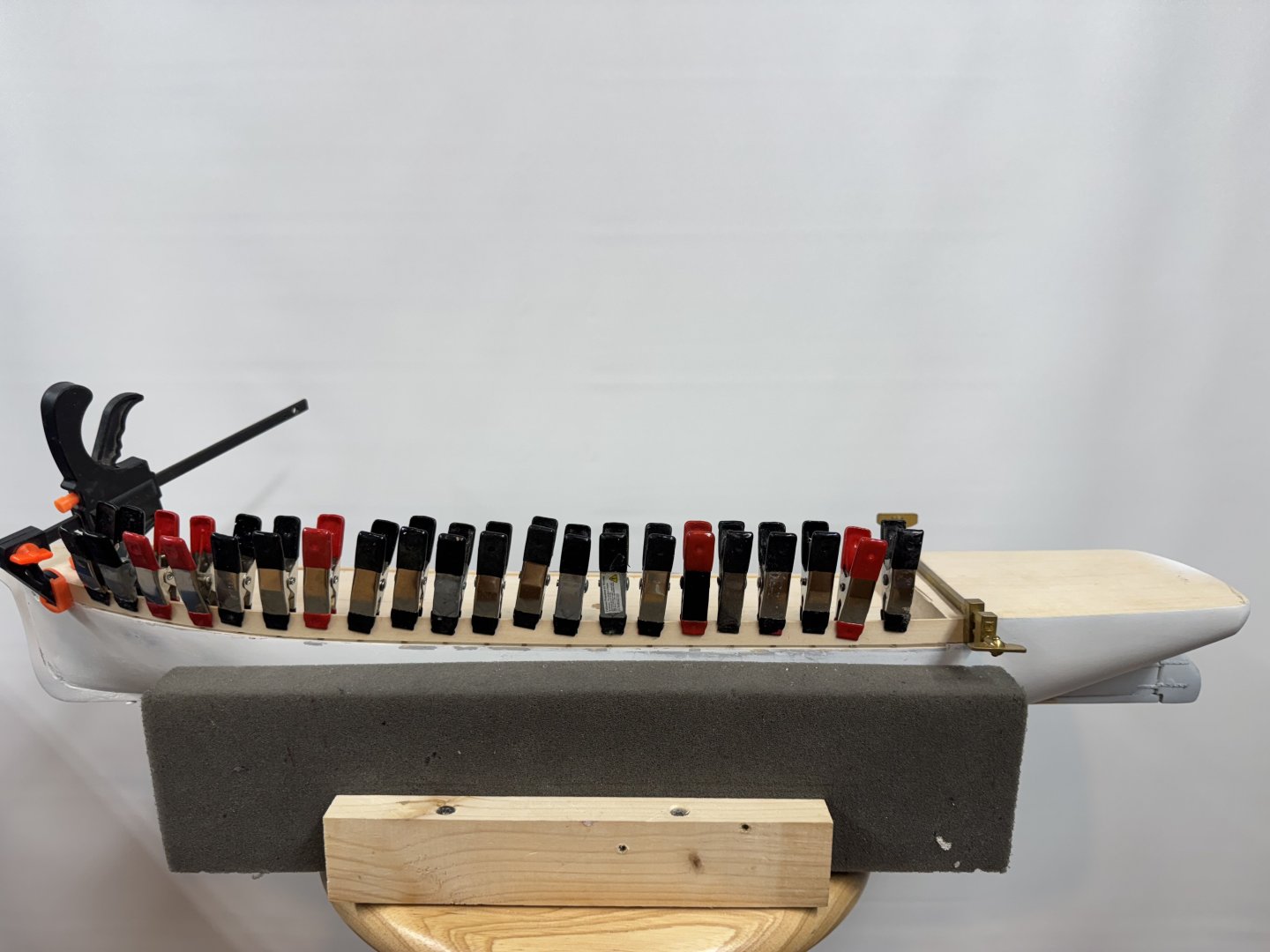
Port side bulwark in place and glue drying. I dry fit the bulwark using clamps on every timberhead and a piece of decking to get the 1/16" spacing between the bulwark and the hull at each timberhead. Then I measured and cut the bulwark to the correct length and refit everything, added PVA to the ends where the bulwark meets the hull and returned the clamps there then painted 60/40 PVA/H2O onto each of the timberhead bulwark joints. Hopefully this will be strong enough to hold things against the stresses caused by slightly deforming the bulwark piece to conform to the sheer of the hull. It does not naturally want to maintain the 1/16" spacing. Once I am satisfied that this is going to "work" it is back top the starboard side.
- 121 replies
-
- 2
-
-
- Lucia A Simpson
- AJ Fisher
- (and 1 more)
-
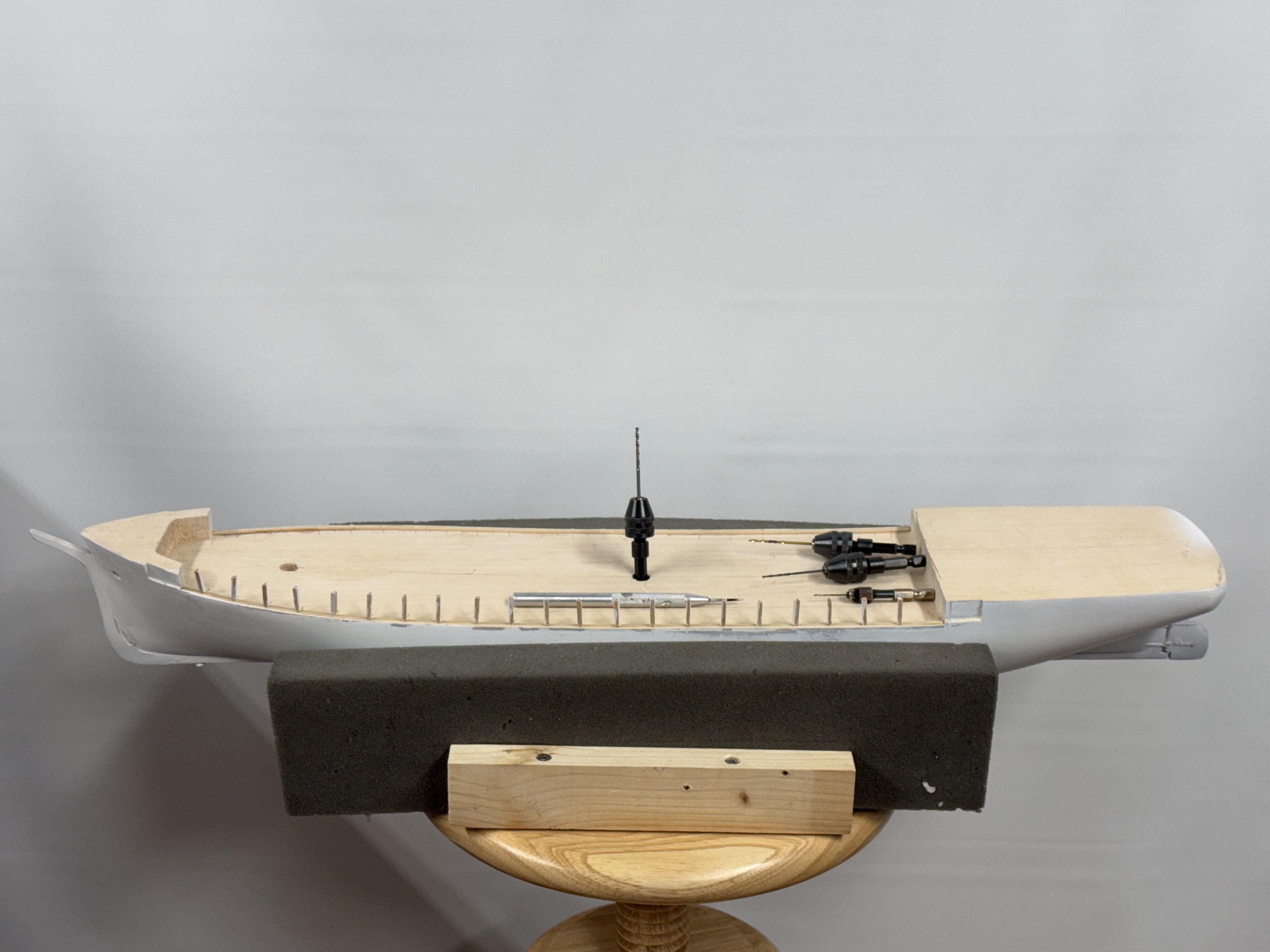
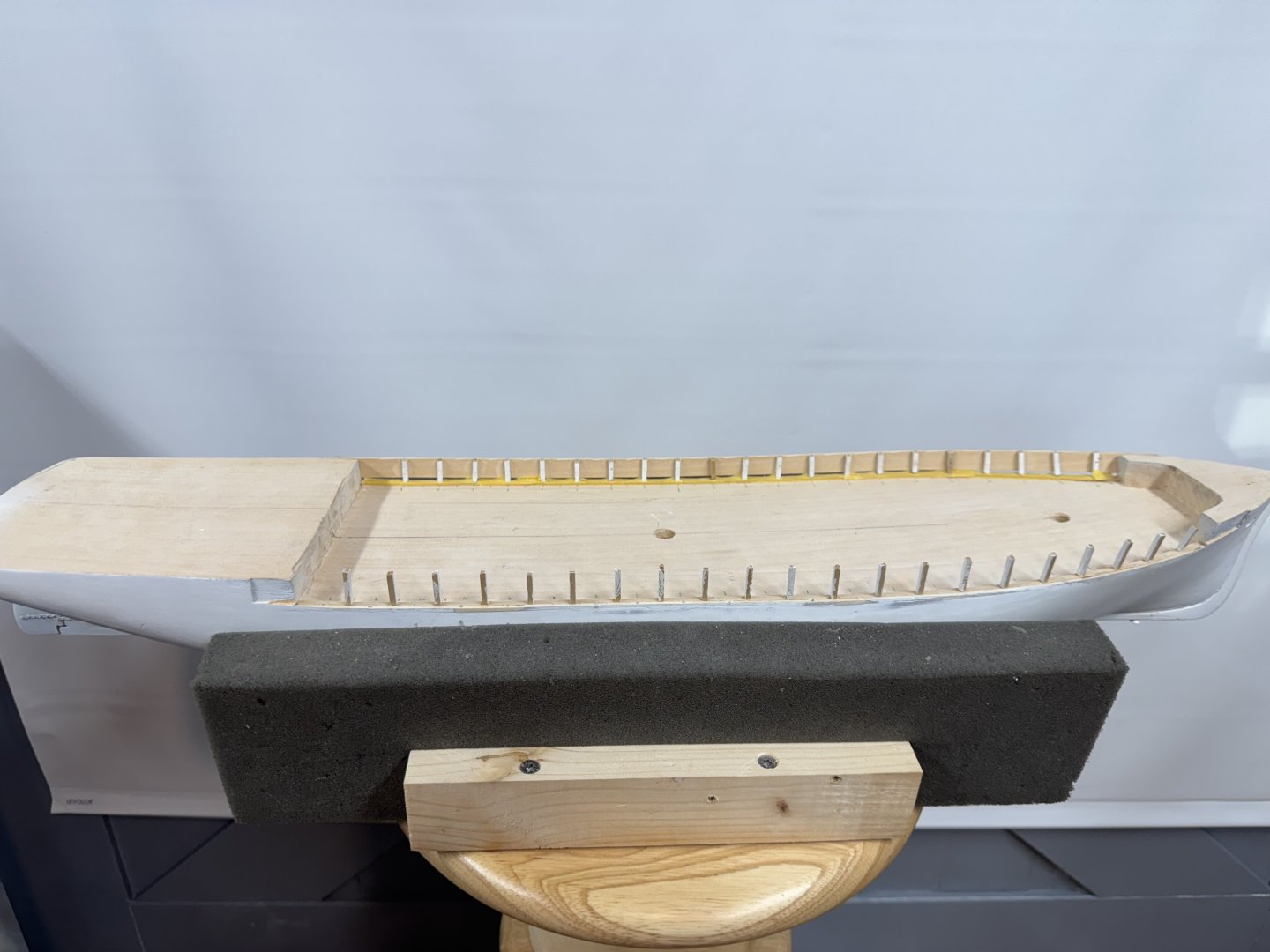
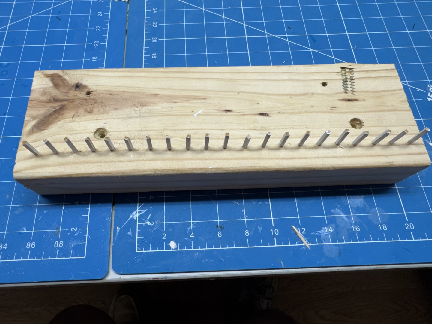
Out of the total 42 port side timberheads 21 are now "installed", not yet glued although that is the next step. The process (somewhat refined after the mis-located holes on the starboard side) is: Locate where the hole needs to be based on the timberhead location marker and just a very bit short of half way across the 1/16" X 1/8" "waterway plank. Then I used an awl to make a fairly deep "divot" where the hole needs to be. A #65 drill bit in the divot to start the hole A #55 drill bit (I wanted something about half way between the #65 and the 1/16" bit) to make the hole bigger - discovered going directly from the #65 to the 1/16" sometimes the 1/16" wandered a bit, especially if I forgot to un-reverse the drill before starting the hole. A 1/16" bit marked with the hole depth (blue Sharpie on the bit) Test fit a timberhead - if the hole is too small re-drill with 5/64" bit. Here is the hull now with the casT of character on deck. Now the challenge is to get the bulwark glued to the timberheads while maintaining the 1/16" scupper gap. Could be a slow moving process but I want to get one side of the bulwark installed before moving to the other side. Don't ask me how I know but it is not very hard to snap one of the timberheads off with a causal movement. Best they be glued to the bulwark before moving on.

- 121 replies
-
- 4
-
-
- Lucia A Simpson
- AJ Fisher
- (and 1 more)
-
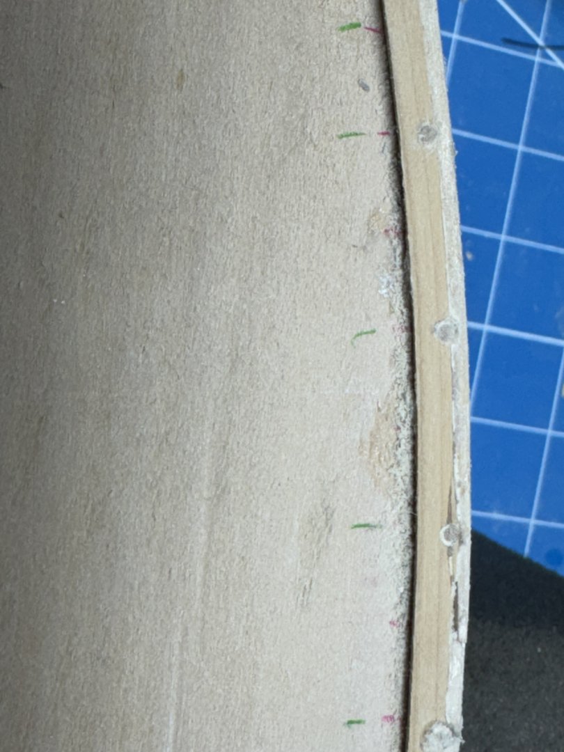
And now for the "big problem". When I laid out the main deck for the timberheads I marked every other location 3/8" on center as where one of the doweled timberheads would go. When it came time to drill the holes for the timberheads I first used a awl to mark the spot, then a #65 drill bit to mark a good "starting point" and then a 1/16" drill to make a hole large enough (hopefully) for the timberhead to fit. Somehow I got it in my mind that the hole needed to be just a very tiny bit inboard on the 1/16" X 1/8" "waterway". That would work fine if the bulwark was supposed to be outboard of the existing hull but that is NOT the case as I figured out when I tried to fit the bulwark to the installed (but not glued) timberheads. Imagine my surprise when things did not look correct and I realized that the timberheads were more or less 1/16" to far outboard for the bulwark to match up as required. So what to do? I initially tried to widen the holes inboard a bit and sand down the timberhead to keep it inside the existing hull (marked by the 1/16" X 1/16" spacer at the outer edge of the hull - added to keep the scupper slot at deck level). That was only of limited success so I finally gave up, removed the timberheads that were not stuck in the holes, glued in 1/16" dowel or cut-off toothpicks to the holes. Cut everything as close to flush as possible then sanded down the bumps". Here is what a section of the starboard side looks like now. I am inclined to leave "well enough" alone, at least for now. I plan to shift the doweled timberheads to the "other" set of locations and most of these "mistakes" will be covered up by the non-doweled timberheads. At least that is my story at the moment. I managed to recover 6 of the doweled timberheads so it looks like back to the Dremel tool lather to make another dozen or so. I will work the port side before going back to the starboard. Maybe I will learn where the holes need to be - I think just a hair outboard of the centerline of the 1/16" X 1/8" waterway but will drill one and check (this time).
- 121 replies
-
- 4
-
-
- Lucia A Simpson
- AJ Fisher
- (and 1 more)
-
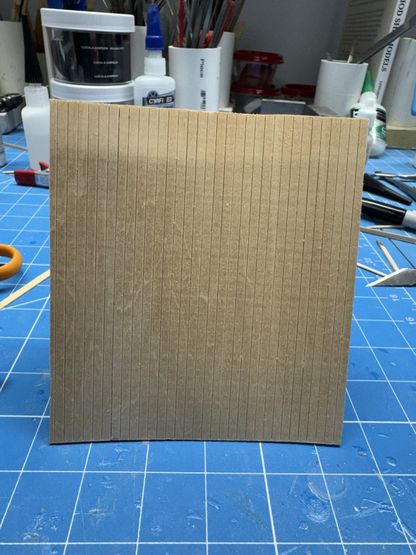
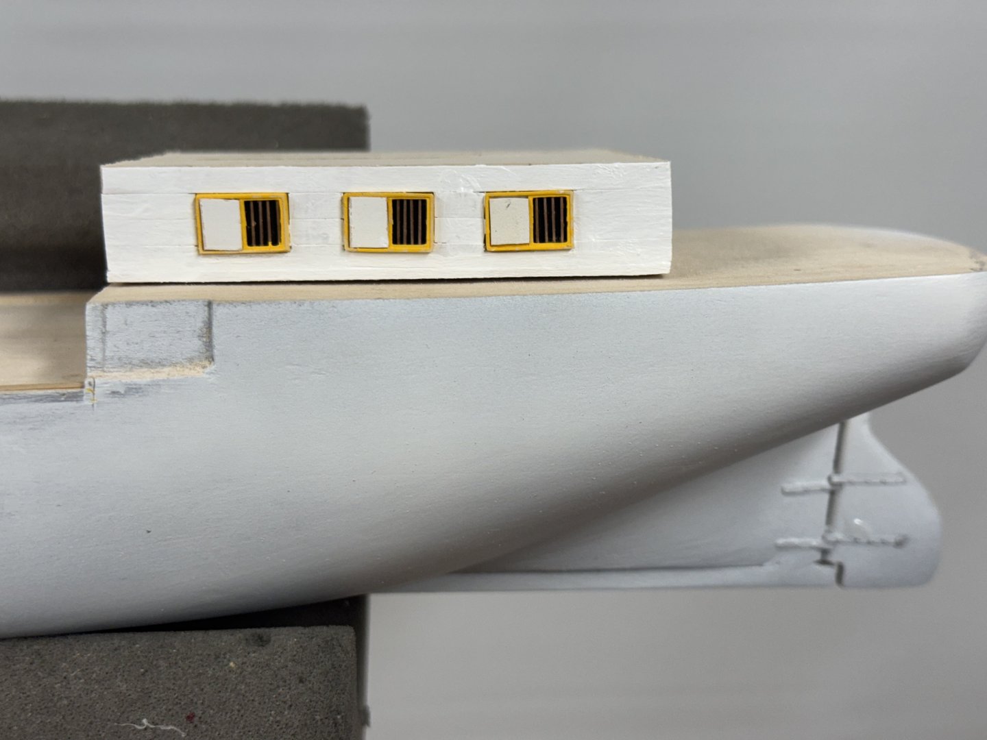
Well said Chris. Here is what the first side of the deckhouse looks like after planking and a touch up painting to better disguise (but not completely hide) the planking seams. Yea, the one slide needs a touch up also. I am kinda at a lose on how to handle the corners. If it were on land I would some styrene angle that looks to be about the correct size but have no idea how the corners were handled onboard. Would hate to do something CLEARLY (to others) incorrect. Any thoughts?
- 121 replies
-
- 3
-
-
- Lucia A Simpson
- AJ Fisher
- (and 1 more)
-
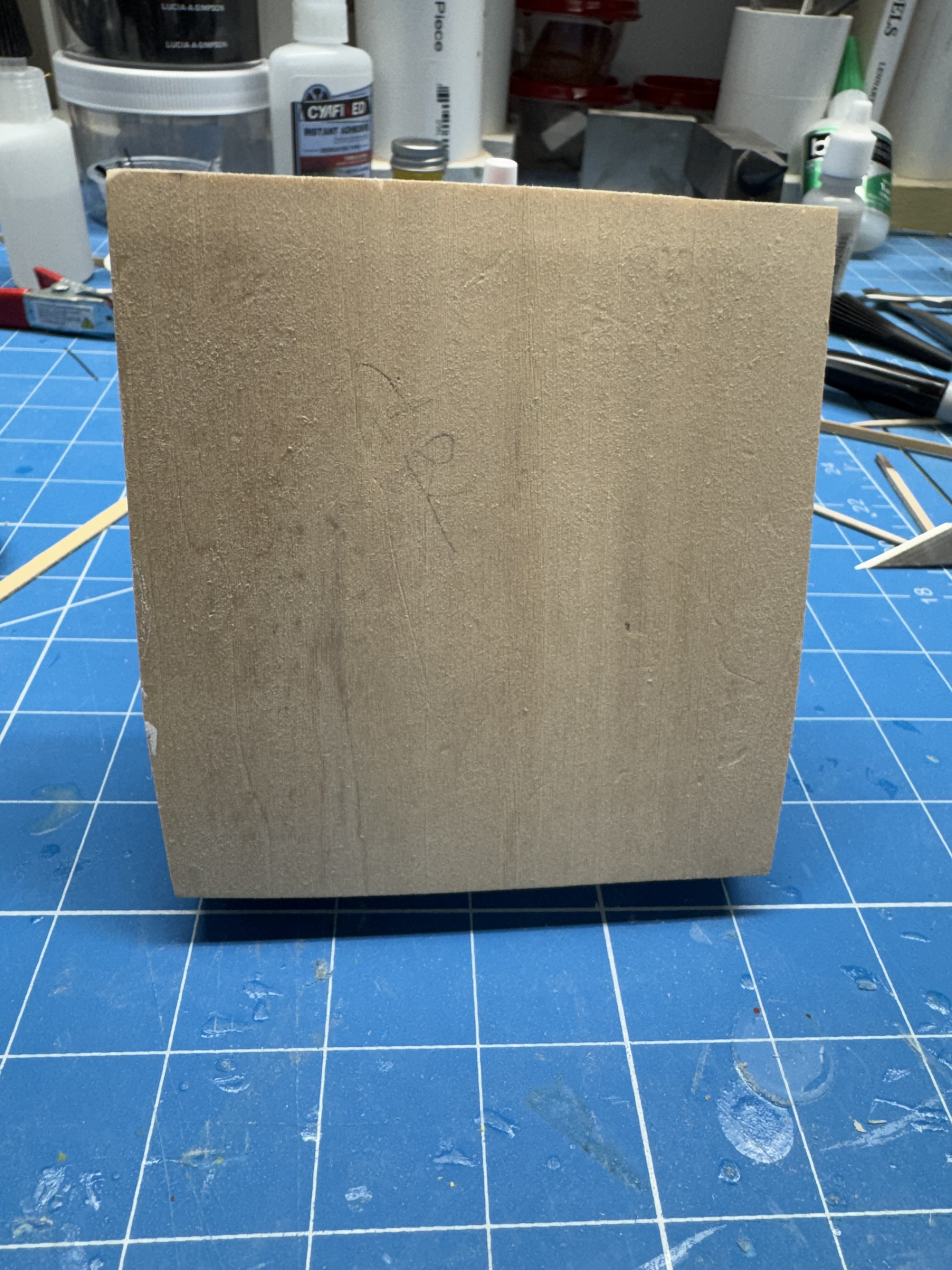
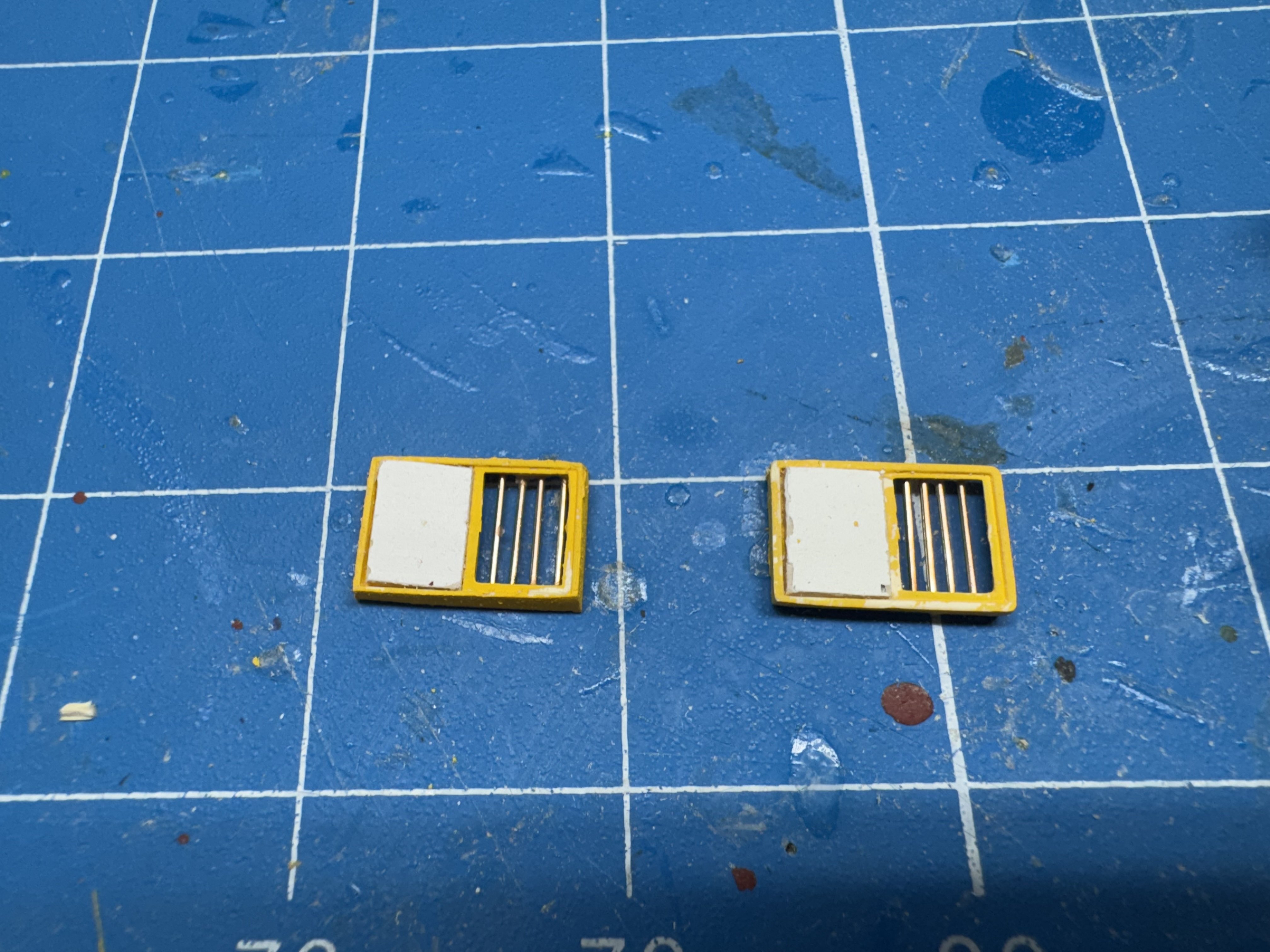
I got tired of working the hull and all the little pieces of timberhead (and I made a big error I need to correct). So I turned to something I thought would be easier - the deck house. What is supplied is a block of wood more or less the correct dimensions. The windows and doors are "left to the student" using strip wood although none of those provided are designated for that purpose. Not having any faith in by ability to make windows out of 1/31" X 1/32" strips I chose to buy them from Northeastern Scale Lumber. Here is one part of what will become the six windows, three on the port and starboard sides. They have had one coat of Vallejo flat yellow so far. I sanded off the sills and outer framework, cut the mullions out of one side and added .020 phosphor-bronze wires to the side without the mullions and cut a piece of 1/32" thick sheet wood painted white for the sliding shutter and here are the first two: A little paint touch-up and I only need four more. Actually this window "type" will become nine of the ten windows turned vertically or horizontally and with or without the sliding shutter. I plan to plank the sides of the deck house with Northeastern Scale Lumber O Scale 1 X 10s which at 1/64 are about 1 X 12s. I also plan to plank the exposed areas of the hull on both ends where, especially at to bow, the "milling machine" left it pretty rough. In fact I should probably start on the aft end so that I don't end up with a discontinuity where the hull "becomes part of the deck house". I should not end up with two narrow planks one atop the other.


- 121 replies
-
- 5
-
-
- Lucia A Simpson
- AJ Fisher
- (and 1 more)
-
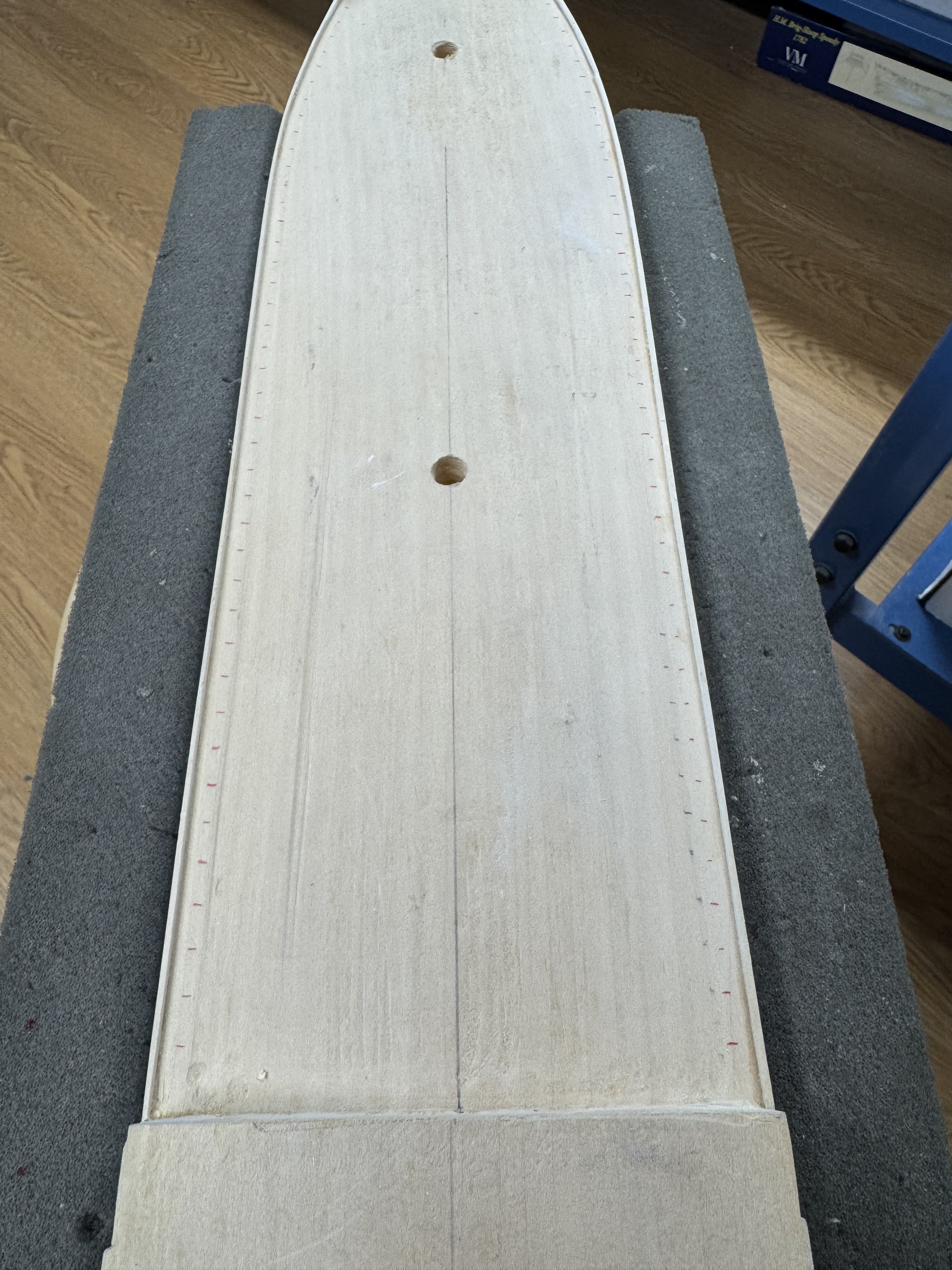
Booms, gaffs and trestle trees are in the "to be installed later" box. Now back to the hull. I marked a batten every 3/8" (center-to-center spacing per instructions) then clamped it to the edge of the deck and marked the deck area of the hull - rinse and repeat on the other side. I decided (being a belt and suspenders kinda guy) that I would used the doweled timberheads at every other location. By my count that is 21 on each side. Here are the first 21 letting the paint (on three sides only) dry. The decking material is due here today (per USPS) so the next step to install the 1/16" X 1/8" "waterway next to the 1/16" X 1/16" strip at the edge of the hull and then start drilling holes". In the meantime I have 21 more doweled timberheads to fab.

- 121 replies
-
- 4
-
-
- Lucia A Simpson
- AJ Fisher
- (and 1 more)
-
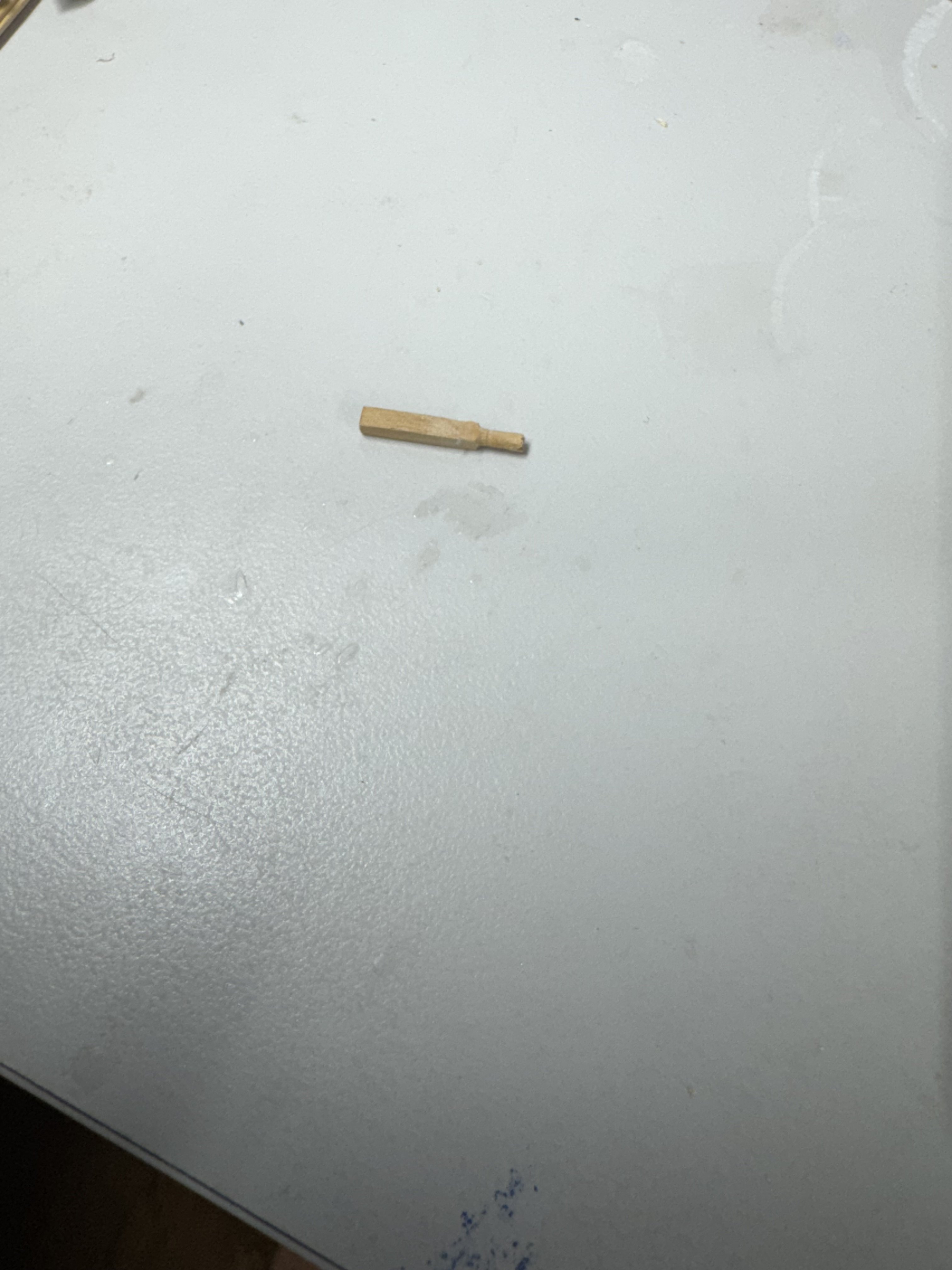
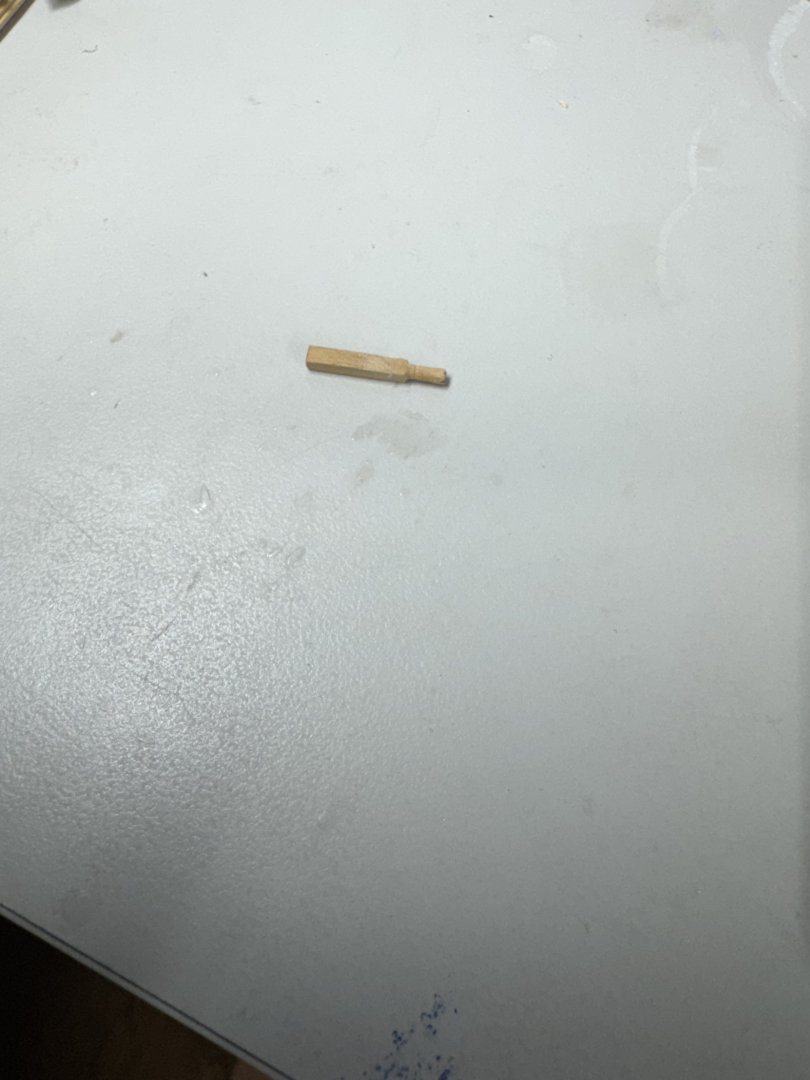
All the booms and gaffs are ready to "go". Next up are the timberheads which ave to be glued onto the deck to help locate the bulwarks which were removed (as option 2) and need to be reinstalled and the gaps filled/sanded/etc. before striking the waterline and painting the bottom. The instructions and drawing do not agree on the timberhead dimensions - instructions say 1/16' X 3/32" the drawing says 3/32" square. I am going with square as I have that size boxwood "in stock". I am going to use boxwood as at least 10 of the estimated (by me) 40 timberheads (per side) that have to have a "doweled lower end" and be seated into holes in the deck. I can chuck the 3/32" square boxwood in my Dremel handpiece, clamp it in my small vice and then turn a circular end on each piece of boxwood then cut it to the required dimensions. Here is my first attempt. I tried to get a better picture using the 2X feature on my iPhone but the site refused to download the picture for some reason but using the 1`X lens is "okay". Only nine more to go. Which brings up the other issue. There is no decking on the hull at the moment except a 1/16" X 1/16" "spacer at the outboard edge of the deck so that the scupper slot will be even with the deck. I am going to plank the deck the old fashioned way. My plan is to start the deck planking with a 1/16" X 1/8" piece and drill the holes for the doweled timberheads in that and then complete the deck planking AFTER the bulwarks are installed and fared in and the bottom has been painted. I am not interested in trying to cut notches to go around the doweled timberheads.
- 121 replies
-
- 3
-
-
- Lucia A Simpson
- AJ Fisher
- (and 1 more)
-
Glad i noticed this first - the peak halyard block is on the wrong side.Yikes what was I thinking? Possibly I was looking at the main/fore gaff drawing which DOES have the block on the wrong side - or is it just my eyes? Anyway it has been fixed and I will have all the blocks on the same side for the fore and main gaffs.
- 121 replies
-
- 1
-
-
- Lucia A Simpson
- AJ Fisher
- (and 1 more)
-
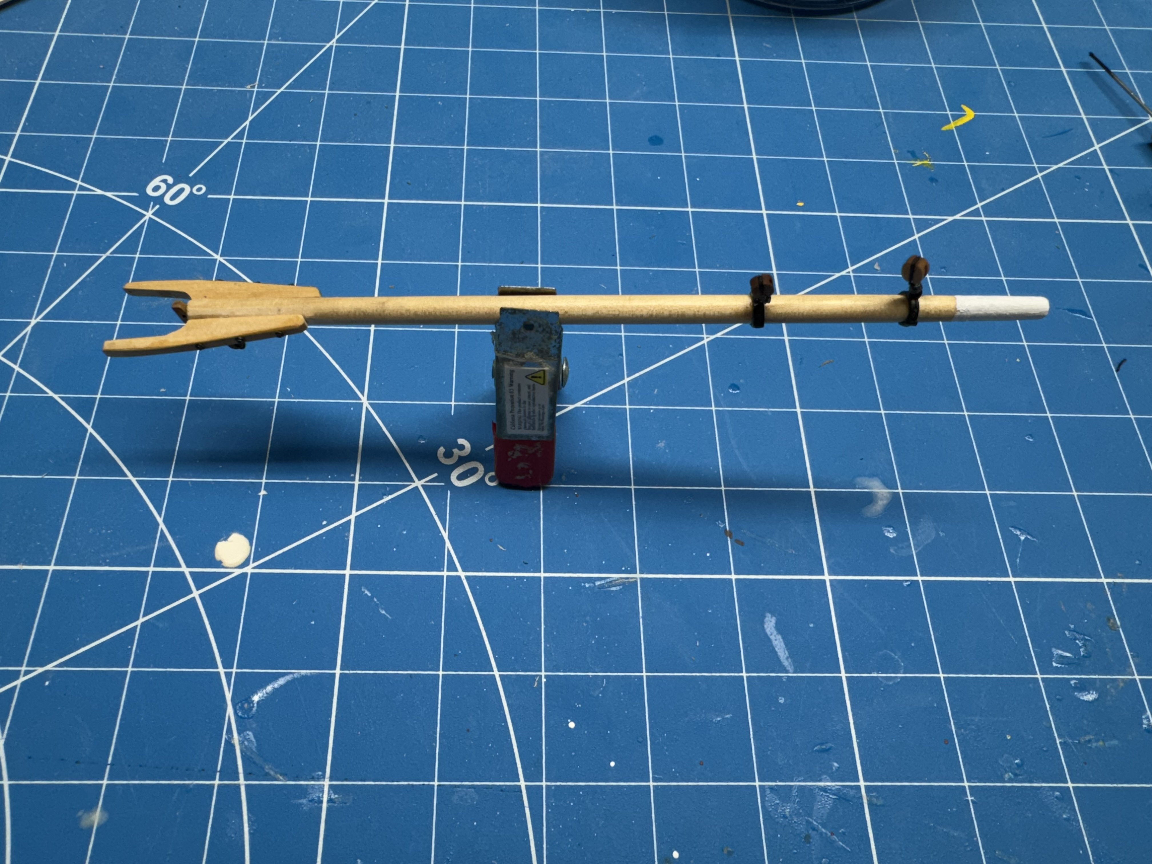
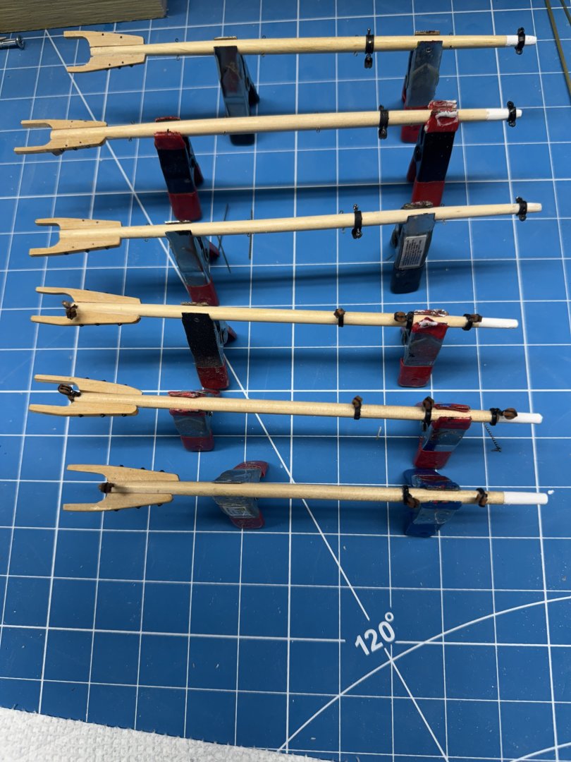
I have gotten the booms as far as I can go at the moment - still need the "chatting block" on the underside of the jaws to sit on the boom support. Will take some "fiddling" to get it as shown on drawing. So on to the gaffs starting with the mizzen since it only has three blocks instead of four like the main and fore (I am not counting the 1/8" block on a short pendant on the main and mizzen as I am not sure I am going to rig all the top sail downhauls since I intend to have to gaffs down sitting atop furled sails. So the drawings shows 5/32 (aka 4mm) double blocks for the throat halyard and two (on mizzen) or three 5/32" single blocks along the length of the gaff for the peak halyard (in combination with the blocks on the mast). So far so good. But the rigging table (on the drawing) calls for a 5/32" triple blocks but it is not clear from the table where the triple would go and the drawing appears to show doubles on the gaff and the mast. Also there are no triple blocks listed on the bill of materials so I am going to assume that the peak halyard arrangement is doubles top and bottom with both ends belayed to the pin rack (per the rigging table). So here is the mizzen gaff with the blocks.

- 121 replies
-
- 2
-
-
- Lucia A Simpson
- AJ Fisher
- (and 1 more)
-
Since the trestle trees have to go on before I can dd the bands and blocks the the lower masts I took another look and noticed that I had not added the bolsters to smooth the transition of the shrouds over the cross trees. I looked at the material list and it shows a 1/4" half round piece for the bolsters. Half round? In all the previous models the bolsters were quarter round not half. And 1/4" seems awfully big since the cross trees are only 1/8". Maybe you are supposed to split the half round piece. Not what I had in mind so I rummaged around and found some quarter round styrene which has the additional advantage of already being white. So I added them to the cross trees. I probably need one more (thin) coat of white , to clean out the pass throughs for the back stays and add the eyebolts and deadeyes (which should arrive this week - they were shipped yesterday according to USPS) and these can go on the masts. That is a piece of the supplied half round which is clearly too big. Maybe cut in half with a very thin kerf table saw blade...
- 121 replies
-
- 2
-
-
- Lucia A Simpson
- AJ Fisher
- (and 1 more)
-
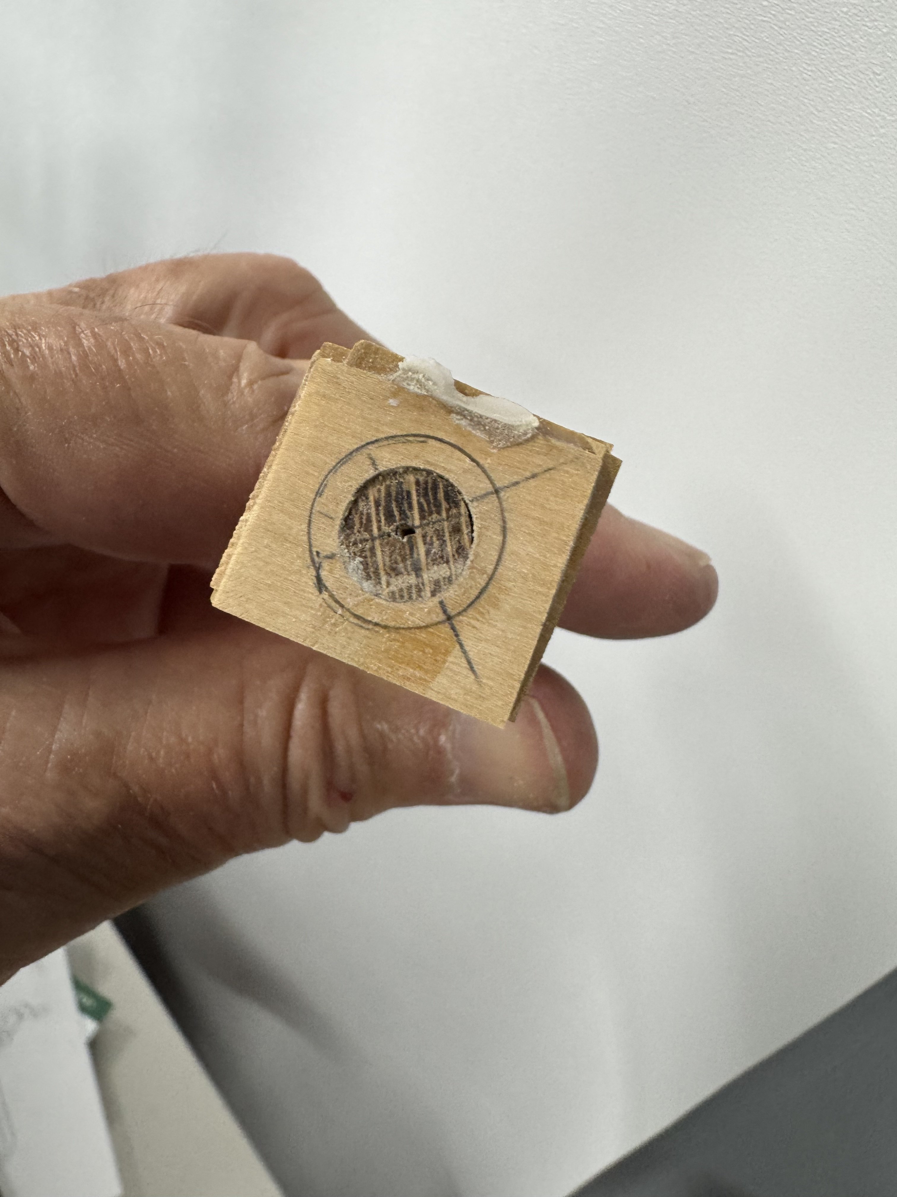
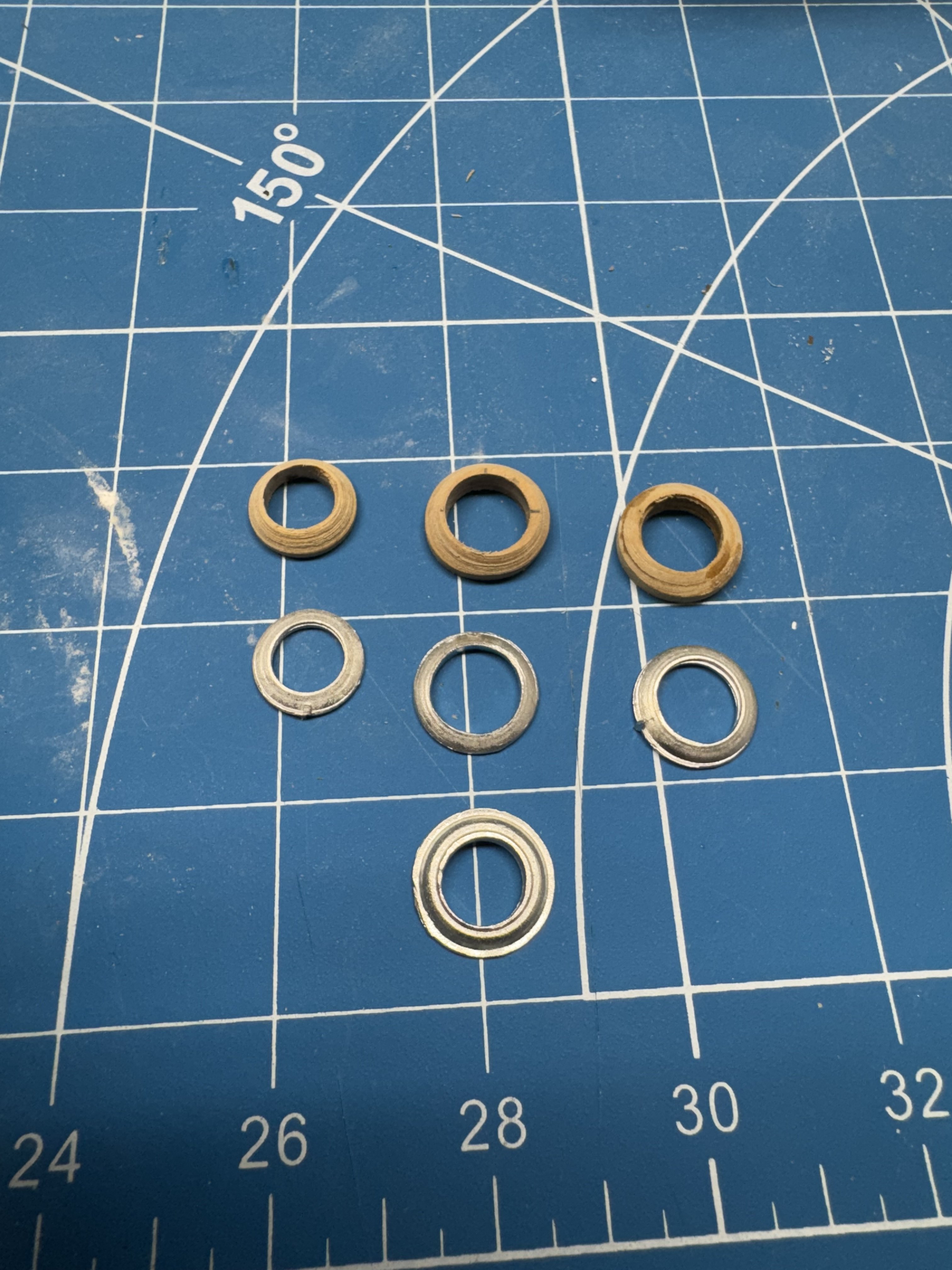
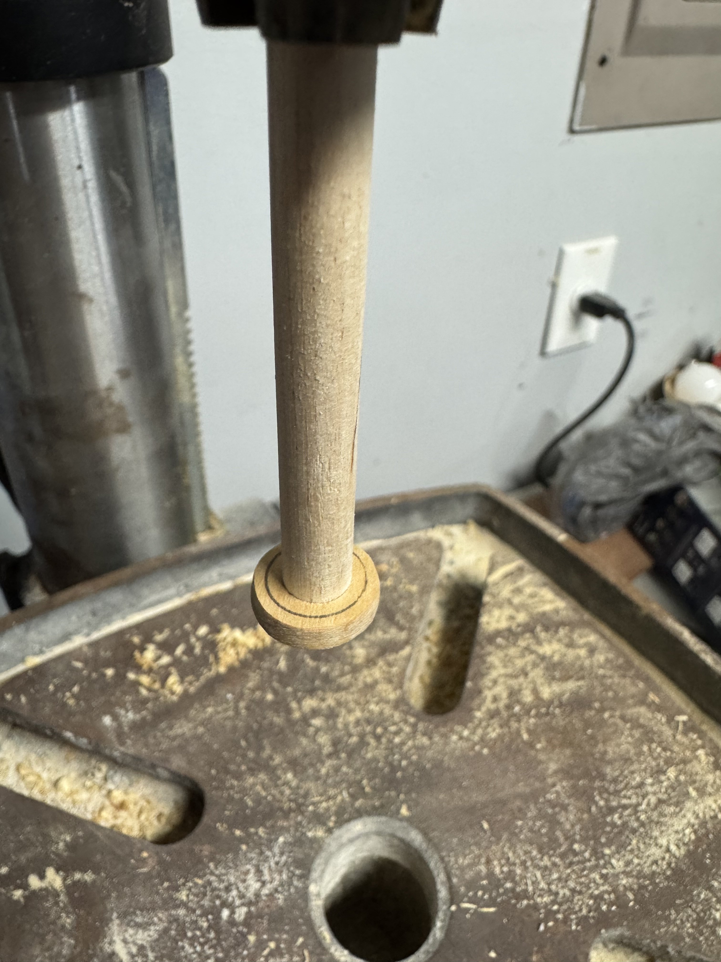
Mast coats - the ones for the fore and main masts supplied with the kit are too small. Before I wasted any time trying to make them fit I ordered two 3/8" ones from Bluejackets. Imagine my surprise when they too are too small - about .05" too small (.325" instead of .375"). I tried to make one fit but it more file work than I was willing to try and when compared to some another mast coat from my parts bin (also in all likelihood from Bluejackets) the new ones are really plain. So I hatched a plan to make my own based on the boom bases I was forced to build from scratch. This time however I drilled the hole for the mast to fit through without worrying too much about getting it exactly centered (turns out al least for me that is not as easy as it might seem). With the hole for the mast drilled in the subject material in this case four pieces of 1/32" boxwood with the grain direction alternating with each piece - I did not have any more 1/16" boxwood readily available sooo...) I fitted the blank onto a short piece of 3/8" dowel that I had previously determined would be a very tight fit. Here is what I mean. Then used a compass to draw the needed outside diameter - 3/32" in this case. If you are following along turn the piece over on the dowel so you can see it while it is mounted in the drill press. Like this: A few passes with a 80 grit sanding stick to get to the correct diameter and then rounding off the outer edge and you have it. Here are the three wooden mast coats (or mast boots as they are sometimes referred to on the fittings web sites), one Bluejackets that I filed out to fit the mast (in center) and the other two were supplied with the kit and older version of the Bluejackets (I think) mast coat I am going to paint the mast coats white as well as the mast sections below the boom base.


- 121 replies
-
- 5
-
-
- Lucia A Simpson
- AJ Fisher
- (and 1 more)
-
With the trestle trees ready for installation I started looking at the eyebolts (12 required) necessary. There are spreader lifts at each mast and that is what the eyebolts are for - to anchor the spreader end of the spreader lift. The spreader lifts are tensioned by deadeyes. Therein lies the most recent disconnect between the materials supplied and the drawings. The list of materials shows 1/8" and 5/32" deadeyes but the rigging drawing lists 3/32", 1/8" and 5/32" deadeyes. For the spreader lifts the drawing 3/32". 3/32" is about 2.3mm which is really, really small. I do not know of a source for deadeyes that small and doubt I would be capable of using them (need really steady hands). I can get 3mm, 4mm and 5mm from Syren. They are 3-D printed so I would not have to worry (hopefully) about the holes not being particularly symmetric. The "problem" that I have found is that at least the "boxwood colored" ones are too yellow for my taste so I am going to order them in imitation Swiss Pear. That ought to be closer in color to what was supplied with the kit. But that means another 5-7 days delay in getting the trestle trees installed as I want to have the deadeyes attached to the eyebolts before they are in the trestle trees.
- 121 replies
-
- 2
-
-
- Lucia A Simpson
- AJ Fisher
- (and 1 more)
-
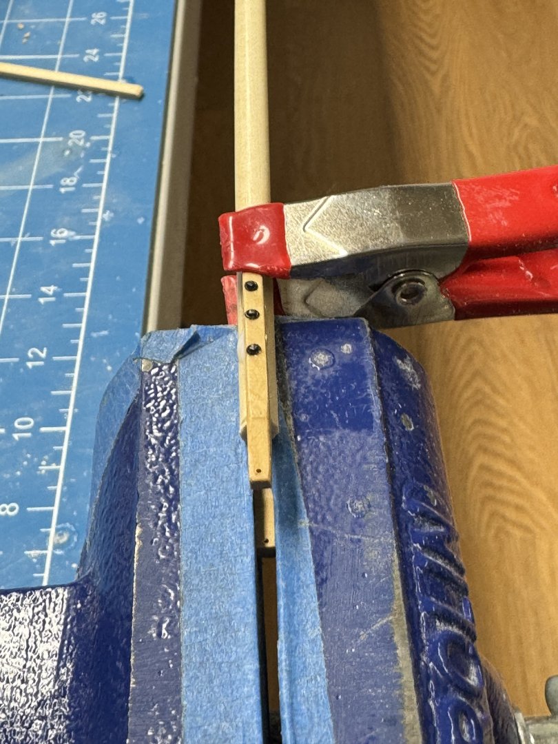
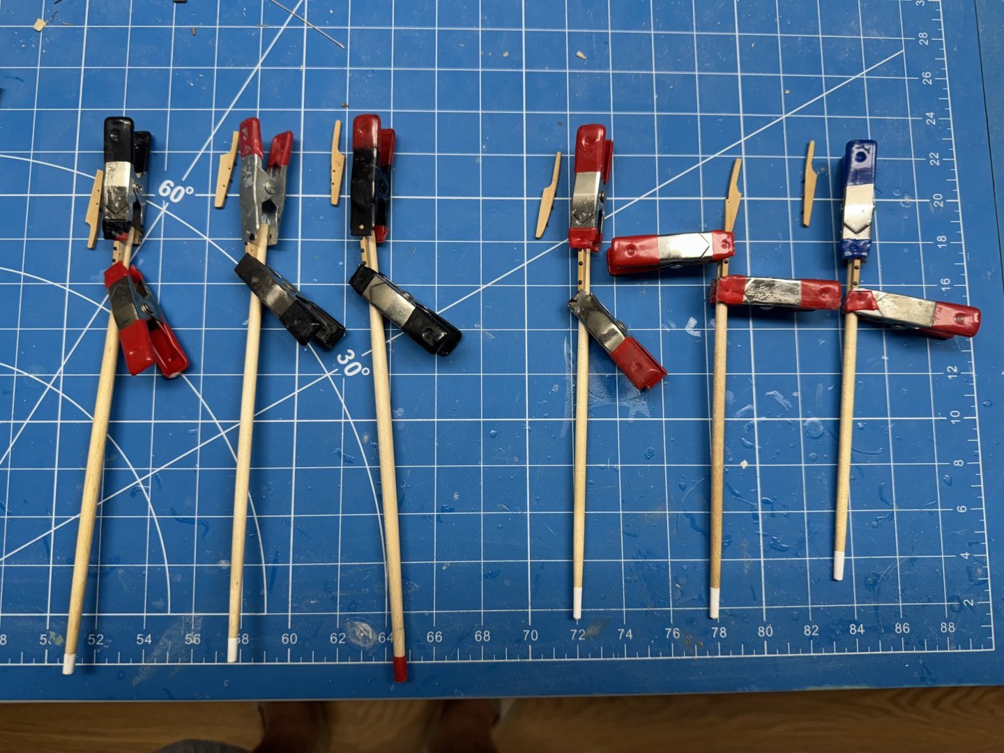
With the first jaw now dry (hopefully) it is time to figure out how to get the second jaw on, hopefully directly across the spar from the first one. My first attempt was to use a clothes pin with one side of both jaws sanded back so they would engage the spar while the outer jaws held the spar jaw. I didn't work out too well and the clothes pin spring was not strong enough to make me think it would be really secure. My second attempt was to place the first jaw in the vice and then carefully sand a flat on the upward facing side of the spar hopefully parallel the the vice top. I had sanded a flat on the side of the spar for the first jaw. With the existing jaw positioned in the vice jaw with 5mm or so of the outboard end of both jaws visible outside the vice jaws I used a medium clamp (they are medium sized to me) to hold the jaw to the spar. It takes some finesse to get the clamp on correctly but it is relatively easy to see (and correct if necessary) the alignment along the spar. A few drops of PVA on the area to be joined and this should work unless the mating surface of the jaw is not more or less flat.

- 121 replies
-
- 4
-
-
- Lucia A Simpson
- AJ Fisher
- (and 1 more)
-
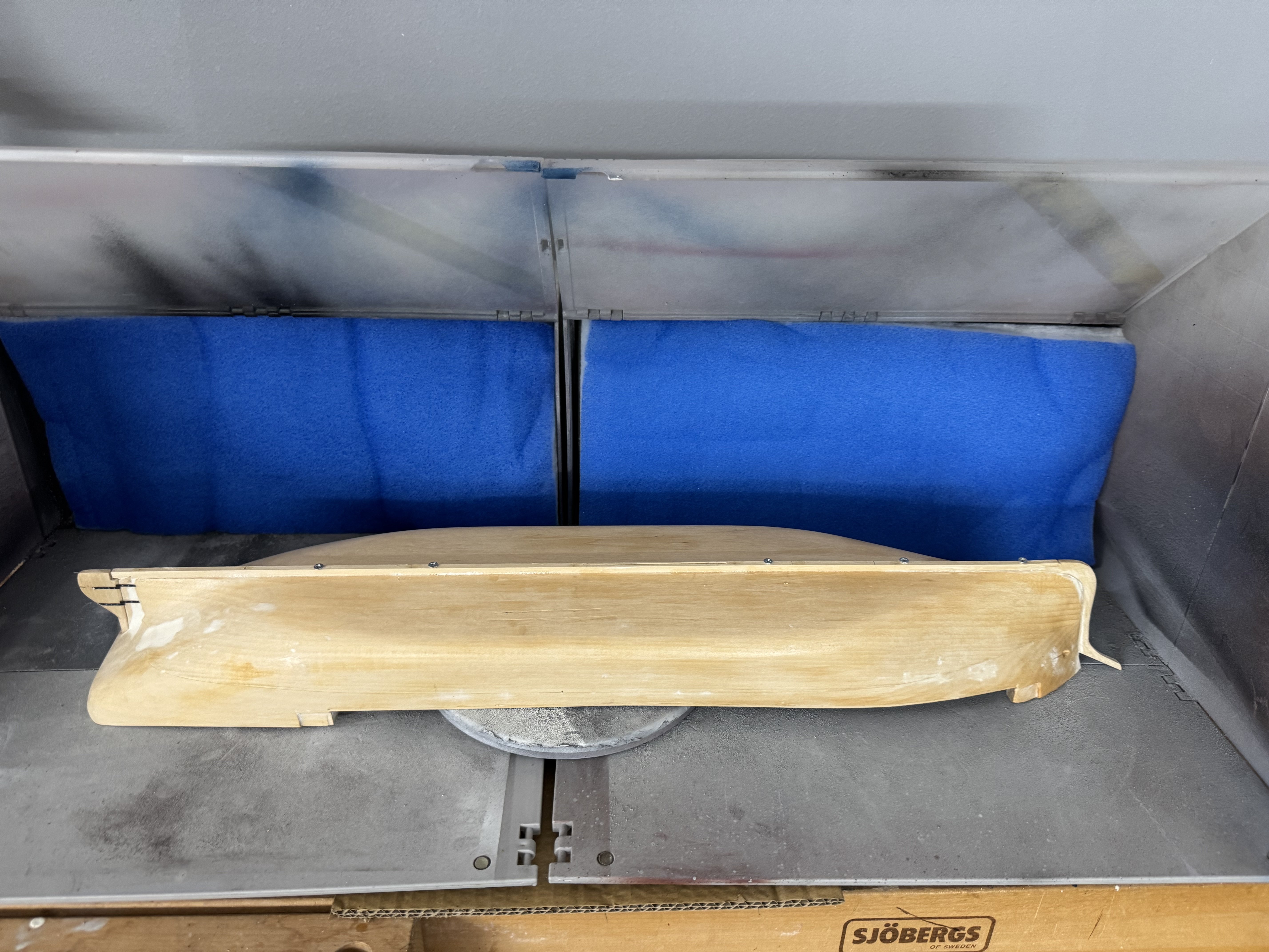
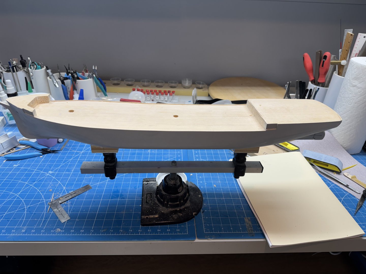
The hull is in the paint booth getting the flat white applied. I am using Testors spray paint. I agonized over the paint choice for awhile. For the out hull spray is great (I used the Testors spray paint on the hull of HMS Sphinx and it looks good. On Sphinx it was the lower hull that was white not the upper so I did not have to address how to paint the upper bulwarks, timber heads etc. Testors sells the same color white in a bottle. It is enamel so it takes forever and a day to dry but it is the only way I can see to get the same color as the spray (my air brush abilities leave much to be desired). I have tried using two different "whites" and it is really hard to get them within an acceptable range of the same color. So while the hull is "otherwise occupied" I painted the tops and the spars (okay I missed one but all will get a second coat shortly) Here are the lower masts Still some touch-up needed. I also added one side of the jaws to the booms and gaffs. I am working on a jig the help get the second jaw attached without breaking off he first side. More to follow.
- 121 replies
-
- 5
-
-
- Lucia A Simpson
- AJ Fisher
- (and 1 more)
-
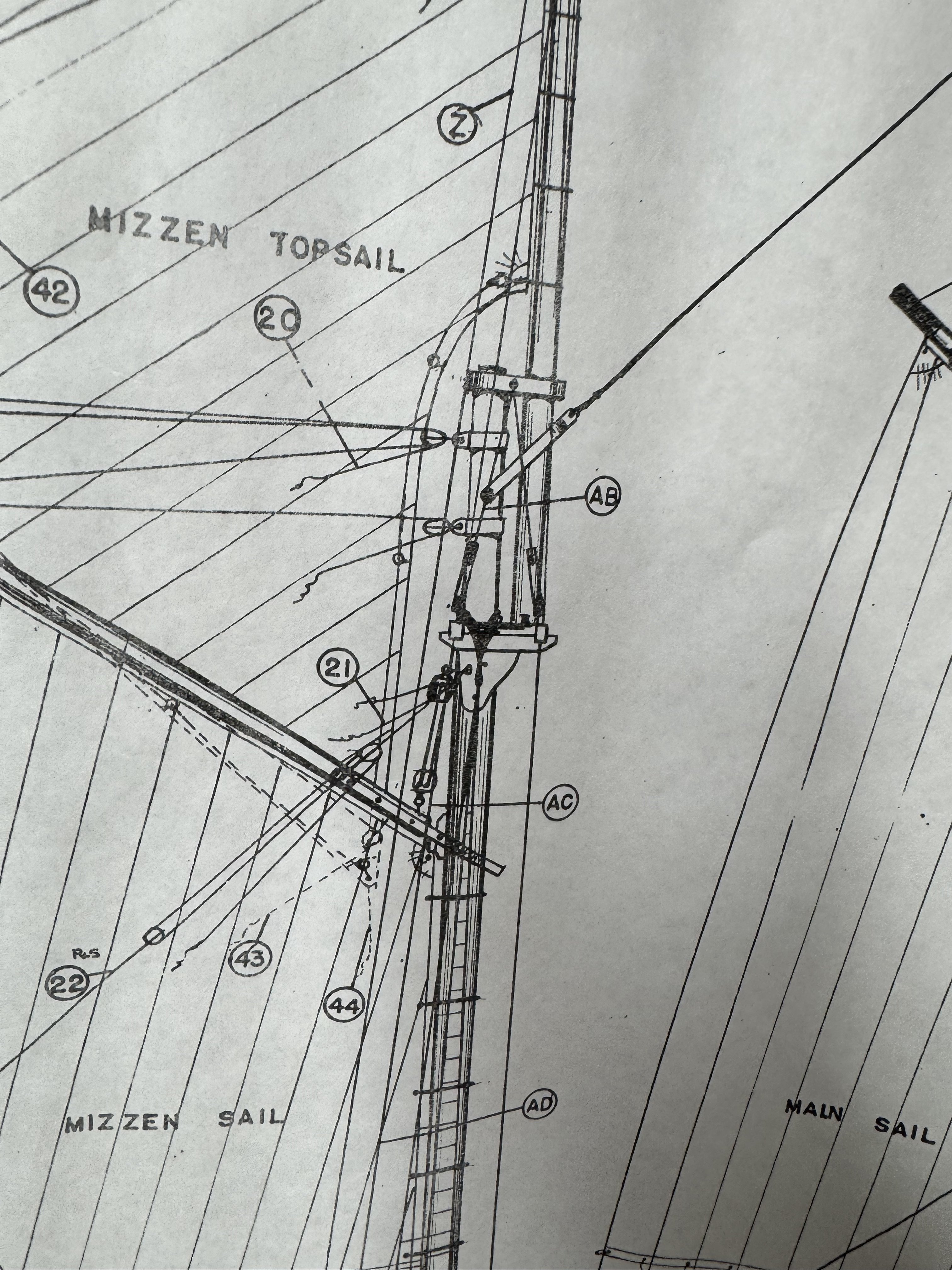
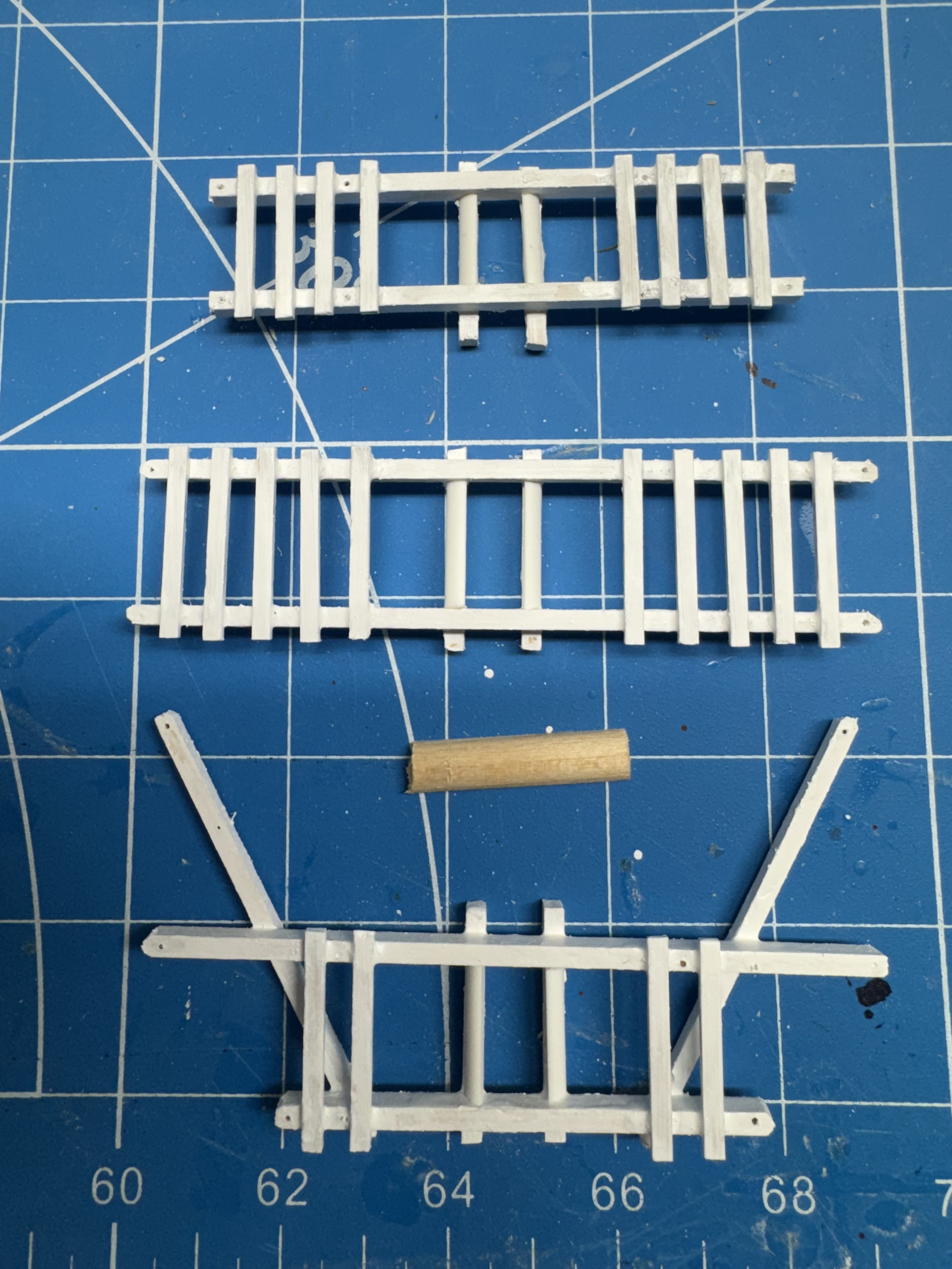
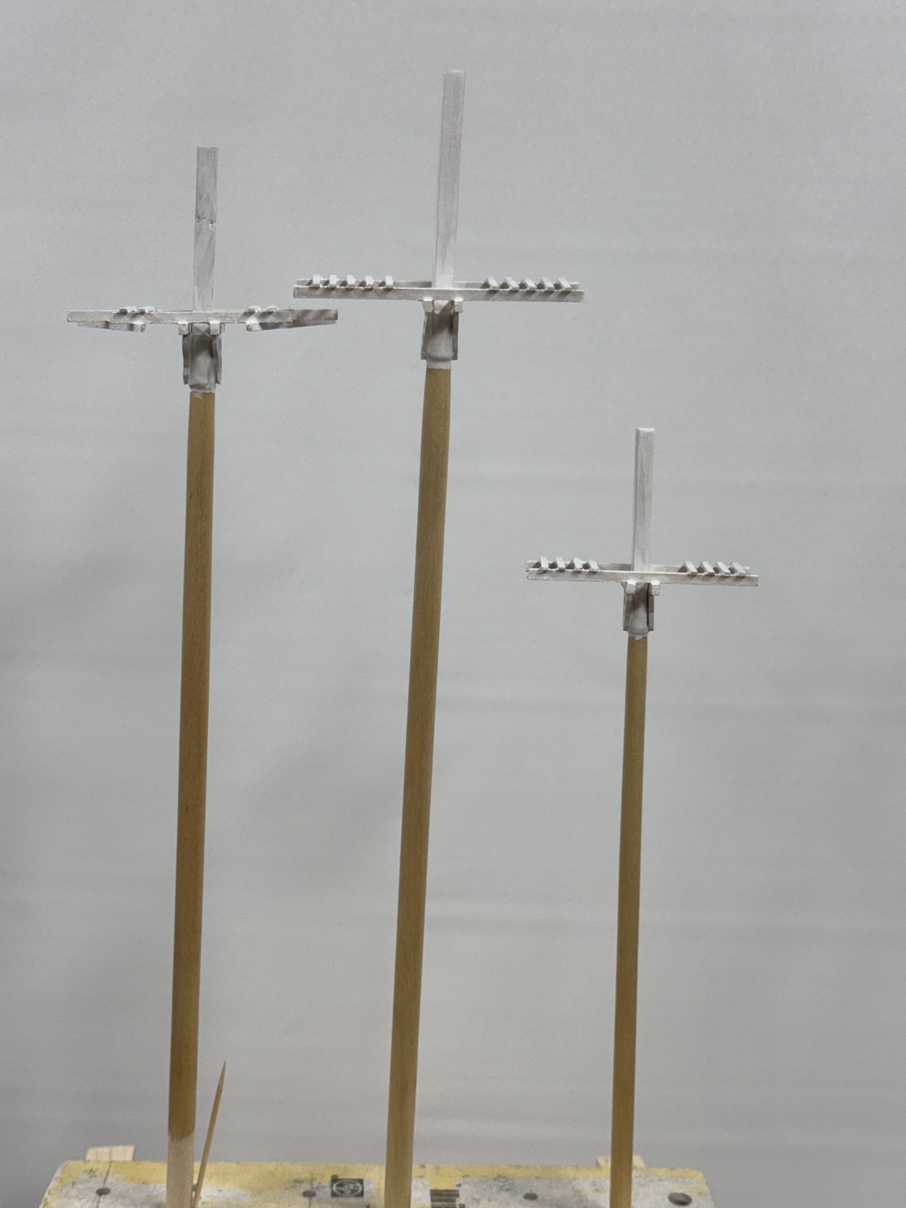
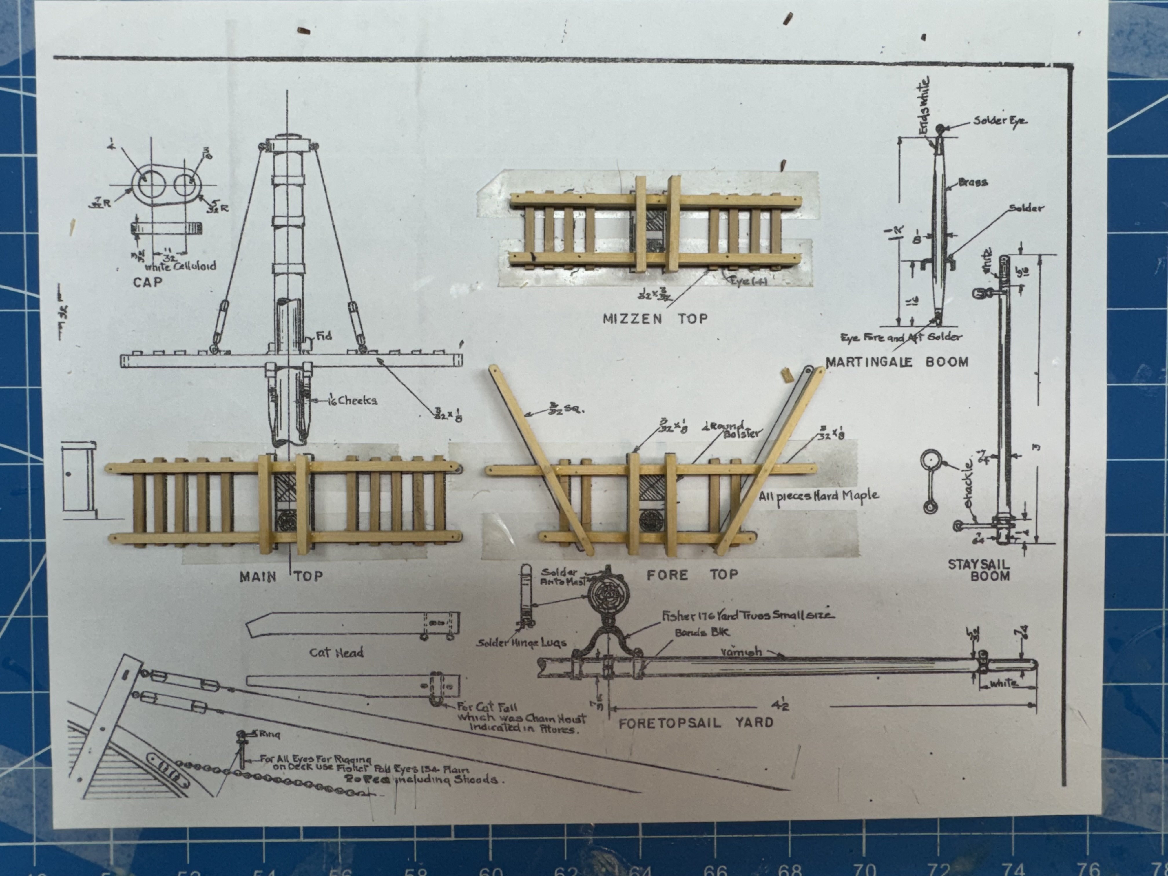
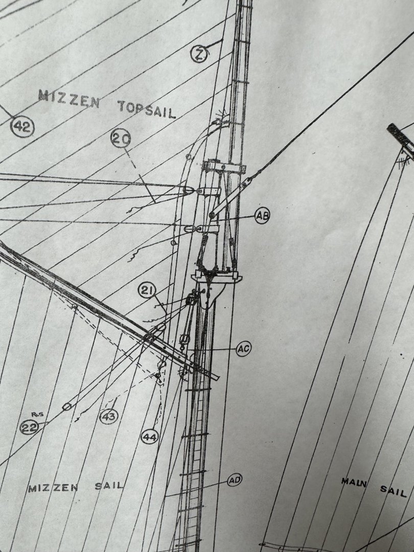
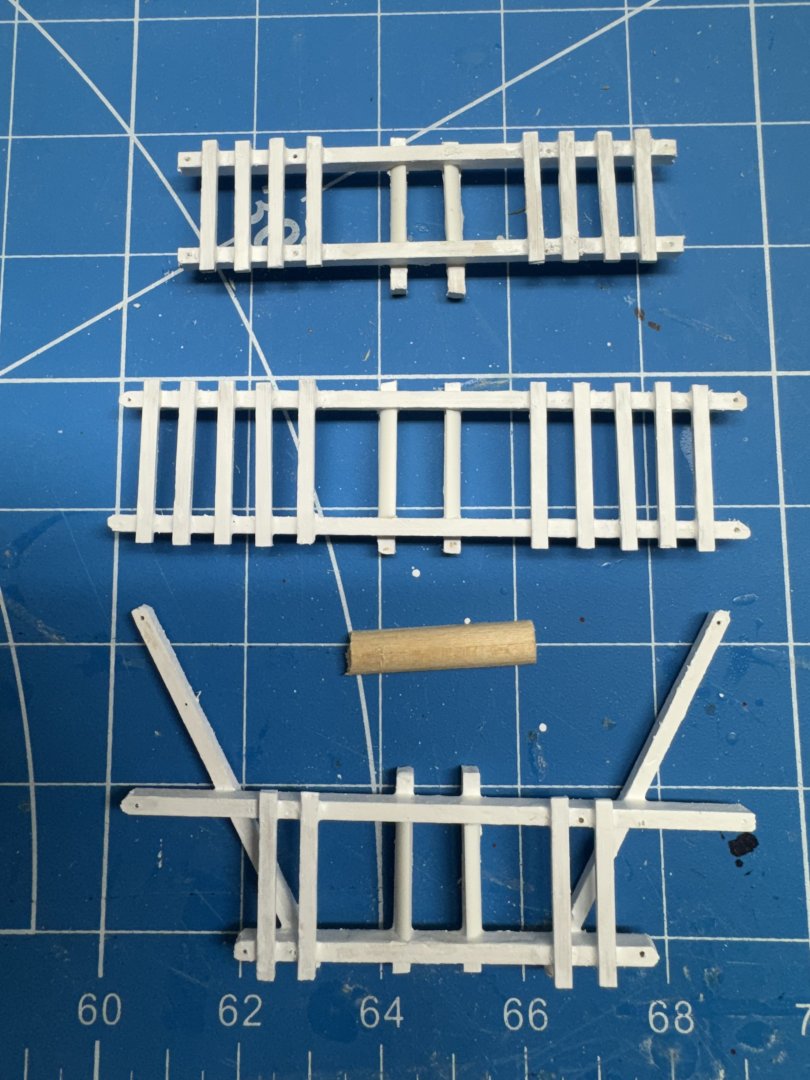
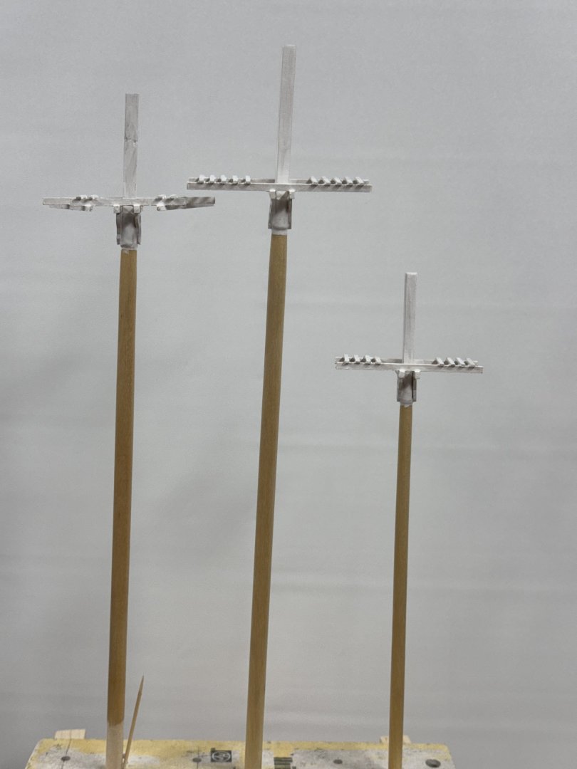
Waiting for the next (and hopefully last) hull filler to dry i worked on the trestle trees and such. I scanned in the applicable portion of the drawing with the details of the "trees". I printed out the portion scanned. Don't bask me how I know but it pays to be cognizant of the default scale setting on the printer you are using. Mine defaults to "fit to paper" which will cause no end of problems if not corrected to 100%. Anyway with the correctly scaled drawing I used double sided tape to hold the various pieces of material in place while the medium CA set up. The kit provided list of materials shows 1/16" X 1/8" material for the cross trees but the drawing shows 1/32" X 3/32". I met them half way using 3/64" thick X 1/8" for the "floor boards" Here are the trestle trees (aka fighting tops on war-of-war ships) ready for the "paint shop". And yes I did check that the rectangular mast tops will fit between the trees.

- 121 replies
-
- 4
-
-
- Lucia A Simpson
- AJ Fisher
- (and 1 more)
-
I am still "toying" with the idea of planking the deck "the old fashioned way but I need to lay in a supply of whatever wood I decide to use if I go that way. I have enough boxwood (I think) but it is 3/64" instead of 1/16" I am n ot sure the lost 1/64" would be noticeable (since it would only be at the outboard edge but it would make getting the timberheads installed since that is exactly where they would go. So to make planking a possibility I test mounted the hull in the Amait carrier and drilled the holes for the fore and main masts using the 25/64" bit as recommended.m I actually HAD a 25/64" bit much to my amazement and it appeared to be in original condition. I am waiting for Amazon to deliver my new white paint before I can start painting white on the spars so I started to look at the boom rests. The instructions say to use 1/8" stock and drill the appropriate sized hole (3/8 or 5/16) and then file/sand to round. Having tried to drill big holes in soft wood (with generally unsatisfactory results) I decided to make my own plywood from two pieces of 1/16" boxwood and then "follow the instructions." Here is the fore mast boom rest and example of the starting point. Getting the 3/8" hole in the center of the marked outer perimeter was not as easy as I had hoped. The fore boom rest is on the mast while I add the supports. I have scotch tape on the mast so the boom rest can be removed when all four supports are in place. I have hopes of putting furled sails on all the masts so the boom rests will come "later".
- 121 replies
-
- 6
-
-
- Lucia A Simpson
- AJ Fisher
- (and 1 more)
-
Thanks Rick. I have the last coat of Wipe-on-Poly on the spars now. Next step is to get the cheeks added to the lower masts and start painting white. Speaking of white paint - there will be a considerable amount of white going forward so I took a look at my white paint inventory. I have a 17ml "bottle " of both the Vallejo 70-951 "white" and the 70-919 "cold white" neither of which is likely to be enough to paint all that needs painting. I tried ordering more of either but the prices (~ $7.00 for one "bottle" plus a delivery charge) were out of sight (can't be tariffs yet?) so instead I ordered the Vallejo "Premium Color" White (62.001) which comes 60ml to a bottle (I ordered 2 - they will be here tomorrow (4/5)) so that should be all the white I will need. Here are the spars now "ready for action" Not easy to see much difference from the last picture but trust me they are all getting smoother with each additional sanding and coat of WoP. I also have the hull ready for it first coat of grey filler/primer. The sharp eyed can see several screw heads showing in the keel. I am building some jigs to allow me to use my Amati "holder" to host the hull once it is ready. I need to make sure the keel is "well and truly laid" as they say and will not pull off the hull since the "tabs" that will mate with the Amati holder are attached to the keel (and hopefully through to the hull as well). I got all the boom and gaff jaws "completed" (aka the bolt heads installed and belaying pin holes drilled).

- 121 replies
-
- 5
-
-
- Lucia A Simpson
- AJ Fisher
- (and 1 more)
-
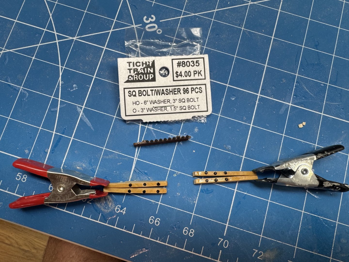
I mentioned previously that I was going to use box wood instead of the supplied basswood for the boom and gaff jaws. I used the previously mentioned technique (it sounds better than scheme) of gluing the jaw outline to a piece of boxwood that is actually two pieces glued together. The disc sander does a good job of shaping both pieces at once with only a minimum of hand work afterwords. Turns out, if left overnight 70% isopropyl alcohol will weaken the PVA glue joint enough to easily pry the two pieces apart. So now I have the jaws for the fore and main booms. The drawing shows three bolts on each side used to attach the jaws to the boom. I would guess that by 1875 iron working was reasonably advanced and they probably had large square (maybe hex) headed screws (or maybe bolts) to attach the jaws. Rather than use steel wire or monofilament fishing line (I have used both) to simulate the bolts I used some small, plastic bolt heads I happened to have on hand. Here are the first two sets of jaws with the bolt heads in place. I had to drill the holes larger than technically necessary because there is a very short "stem" on the bolt and getting them in a smaller (I used #66 drill) was very difficult (for me). I used a small. hammer to tape the bolts in and then brushed on some WoP to act as a sort of glue. Hopefully the bolts will survive installation on the boom. I am going to take these two sets "all the way" to boom installation before committing this method to the other four sets of jaws. Speaking of the other jaws - the drawing does not have a plan view of any of the gaff jaws only the boom jaws. Luckily I noticed that the gaff jaws "horns" are 5mm longer than on the booms. This allows the boom to be at an angle to the mast. I had to extend the horns on my copies of the drawing to use them as templates for the gaff jaws. Just one more of the "little things" that make this kit not something for a beginner.
- 121 replies
-
- 6
-
-
- Lucia A Simpson
- AJ Fisher
- (and 1 more)
-
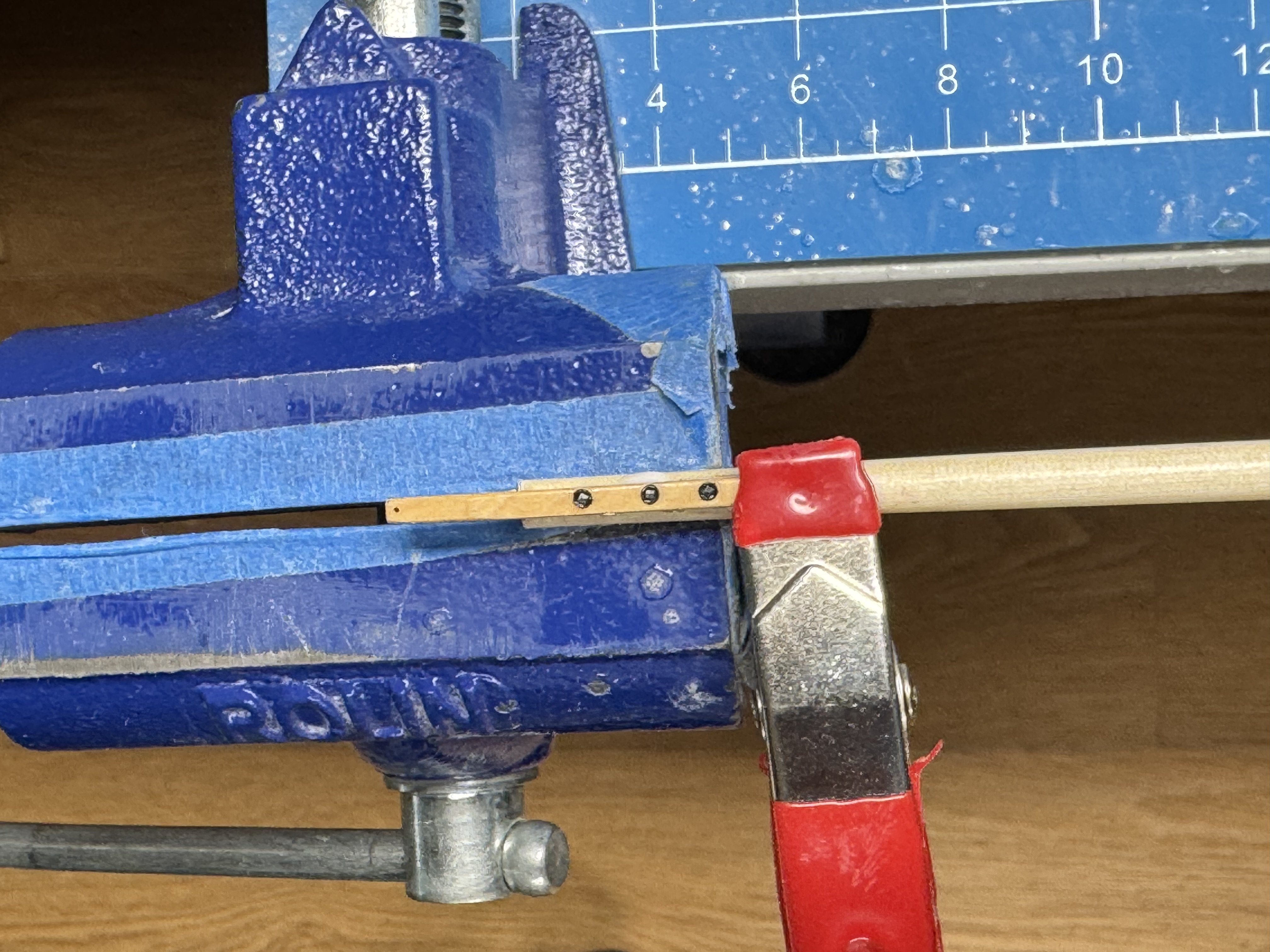
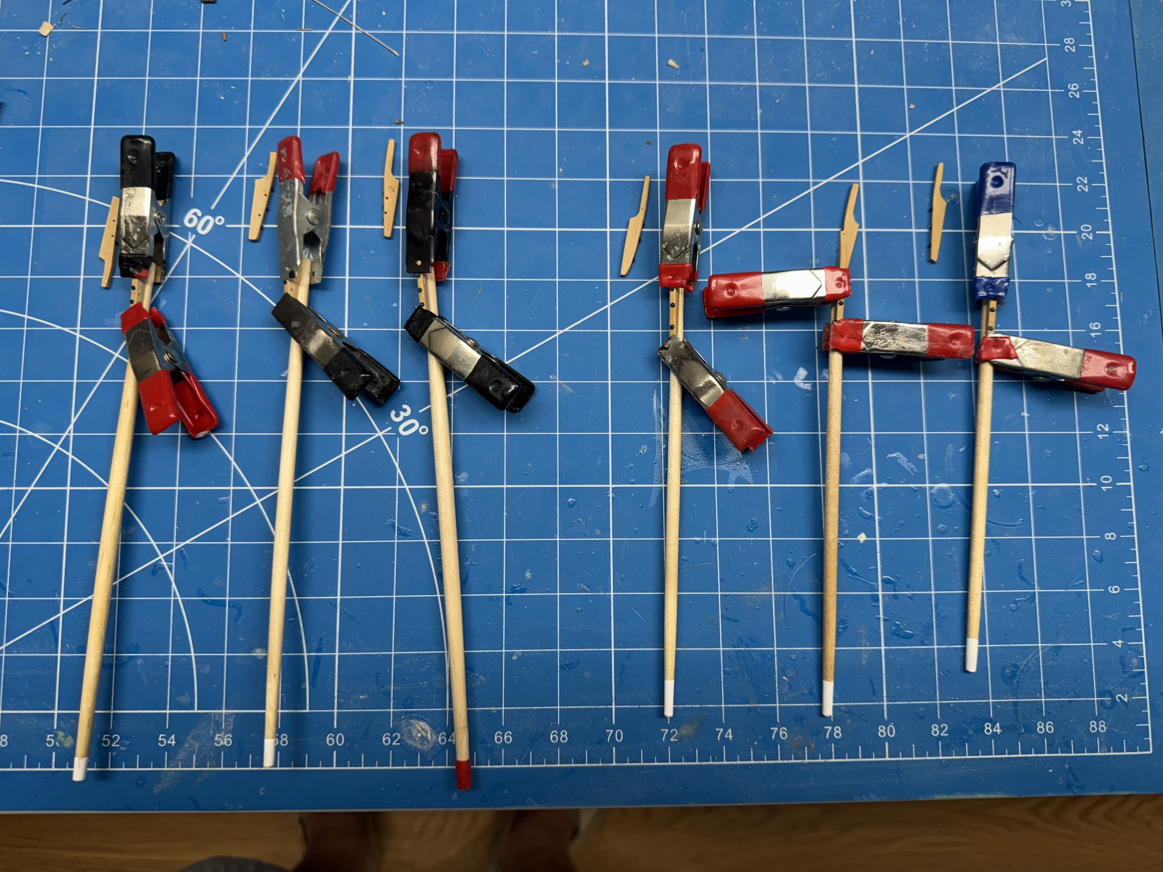
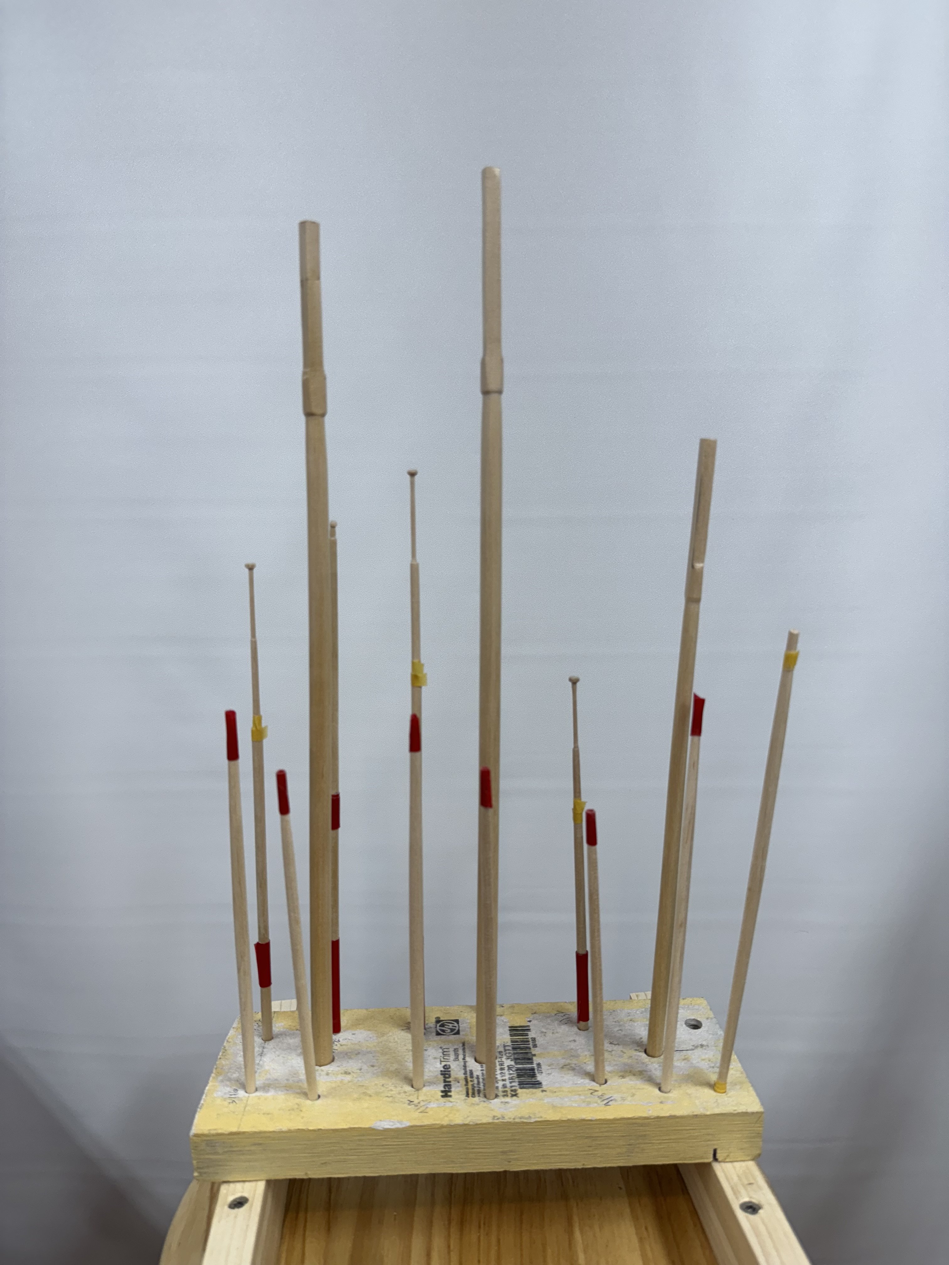
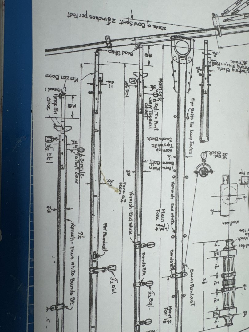
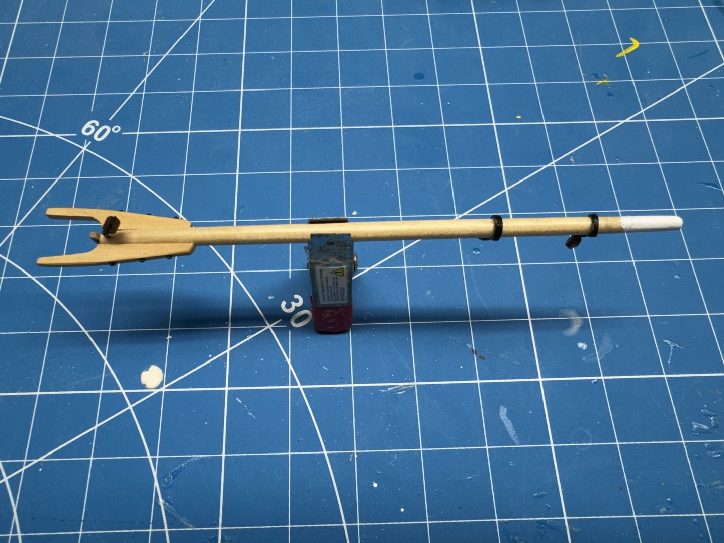
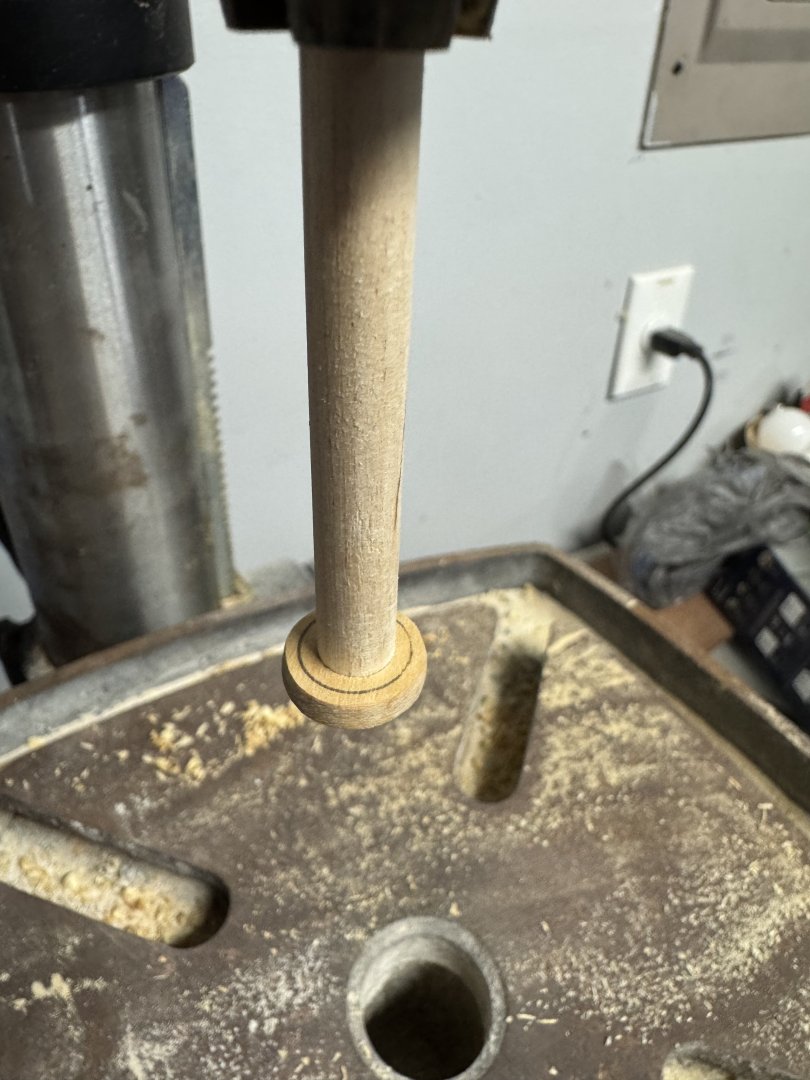
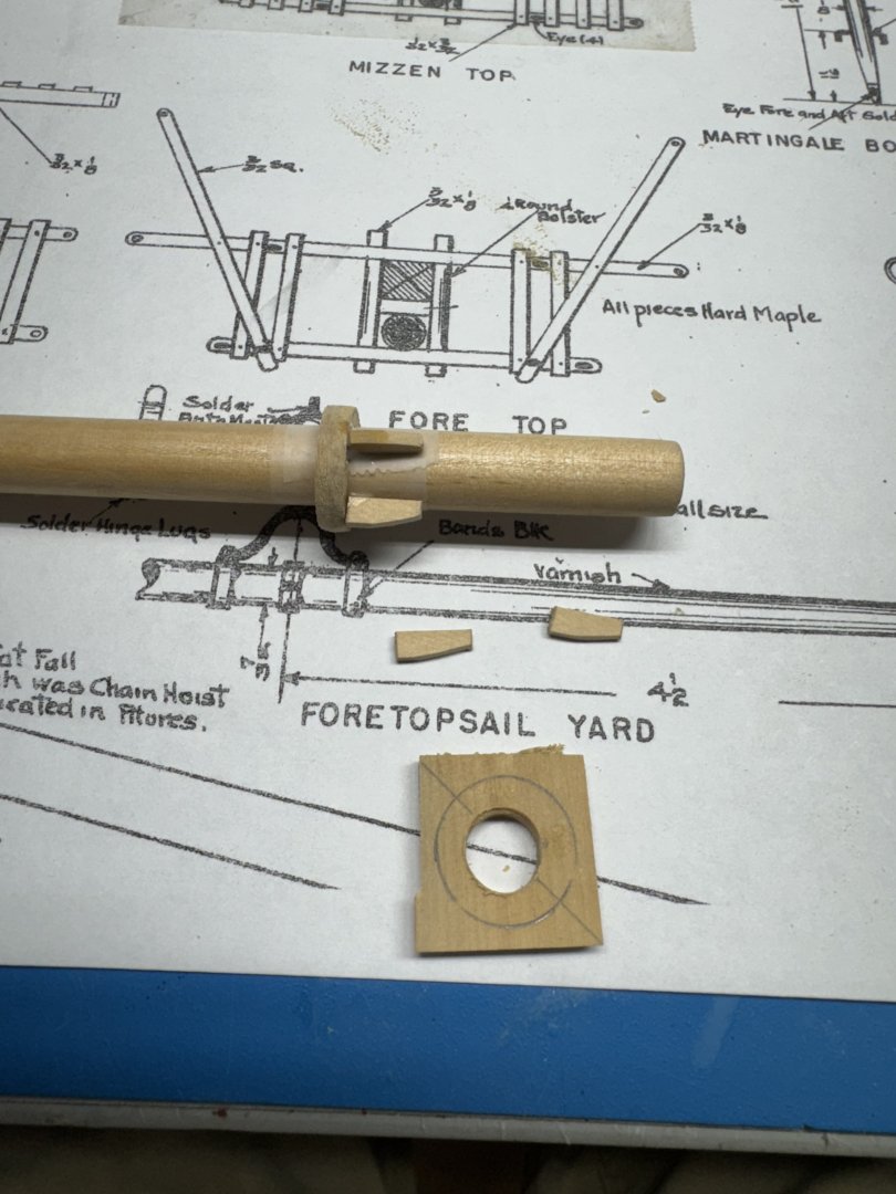
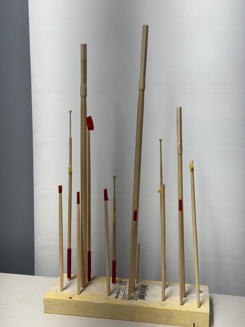
Today was "spar" day. I got all the gaffs, booms, yards and such completed. The top masts were the hardest. The very top segment is 1/16" diameter the entire length and then there is a "gilt truck" on the very top. I spent almost an entire hour last night creating that segment on the fore top mast and figured there must be a easier way to reduce the 3/16" diameter dowel to 1/16". I have a desk top drill press that I have used on occasion to turn masts but never anything this delicate. It works best when there is plenty of extra length in the dowel as chucking the dowel in the drill press will usually mess up the part in the jaws. When necessary I used masking tape on the portion in the jaws if it was needed to get the spar the correct length but that is a last resort as it can make the dowel kinda wobbly which is not good - it leads to the dowel snapping off (don't ask me how I know. Here is a spar (probably not a top mast - (I think this is the jib boom) chucked up in the drill press with the table adjusted so a small portion of the dowel in inside the table opening. I put my left hand on the bottom end of the dowel to keep it steady and used an 80 grit sanding stick to take material off the dowel as the drill press turned at about 1500 rpm. I still had to be really careful with the top masts and rather than going all the way to 1/16" I stopped between 3/32" and 5/64" and then finished off with 220 grit by hand. It still took all day to get the other two top masts, three booms, three gaffs, the foremast topsail yard, the jib boom and the staysail boom ready for varnish (and then paint). The tape you see in the picture below is to keep the varnish (Wipe-on-Poly warm satin) off the areas that will be painted white.
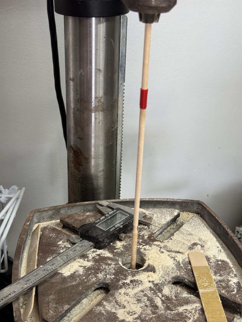

- 121 replies
-
- 7
-
-
- Lucia A Simpson
- AJ Fisher
- (and 1 more)