cdrusn89
-
Posts
1,919 -
Joined
-
Last visited
Content Type
Profiles
Forums
Gallery
Events
Everything posted by cdrusn89
-
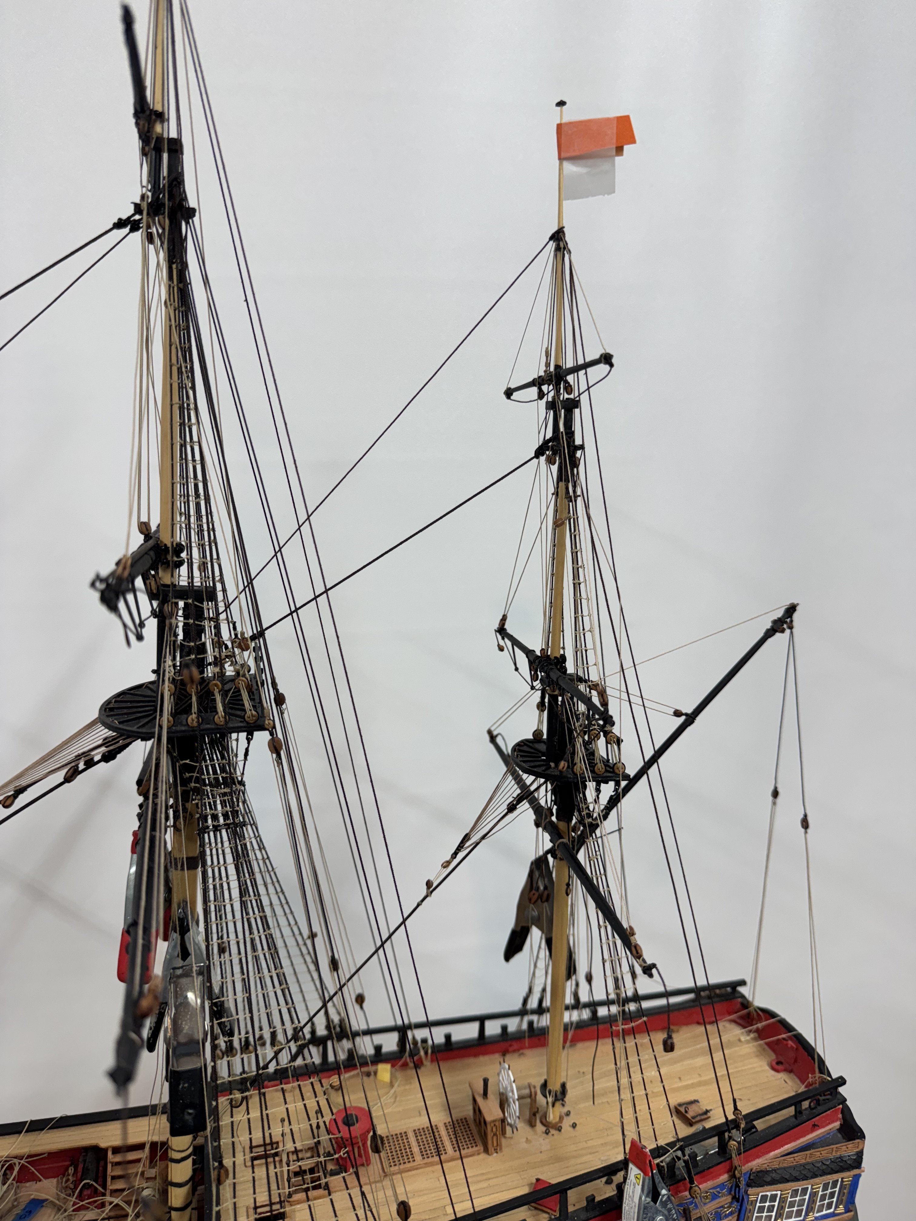
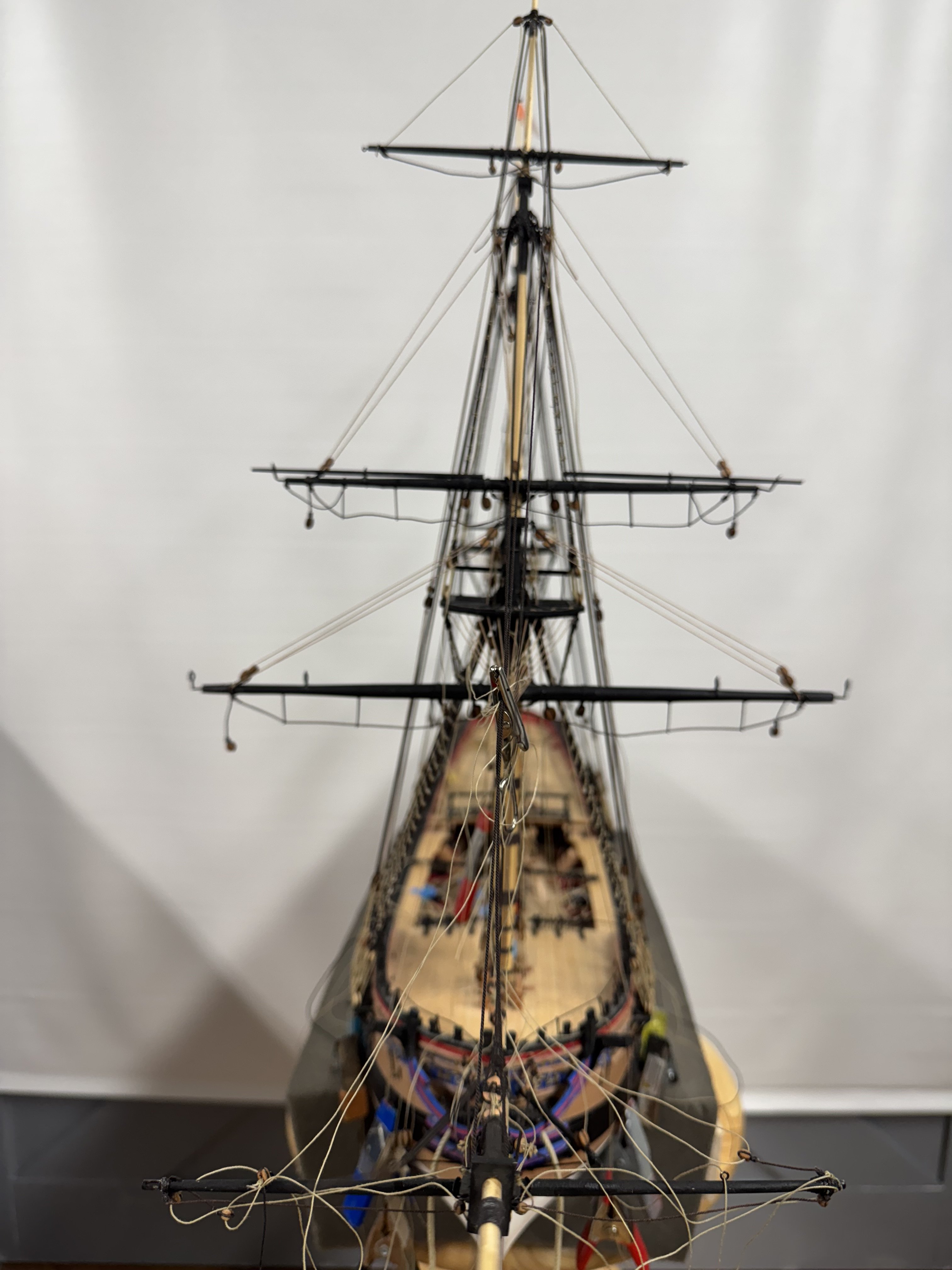
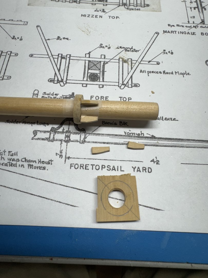
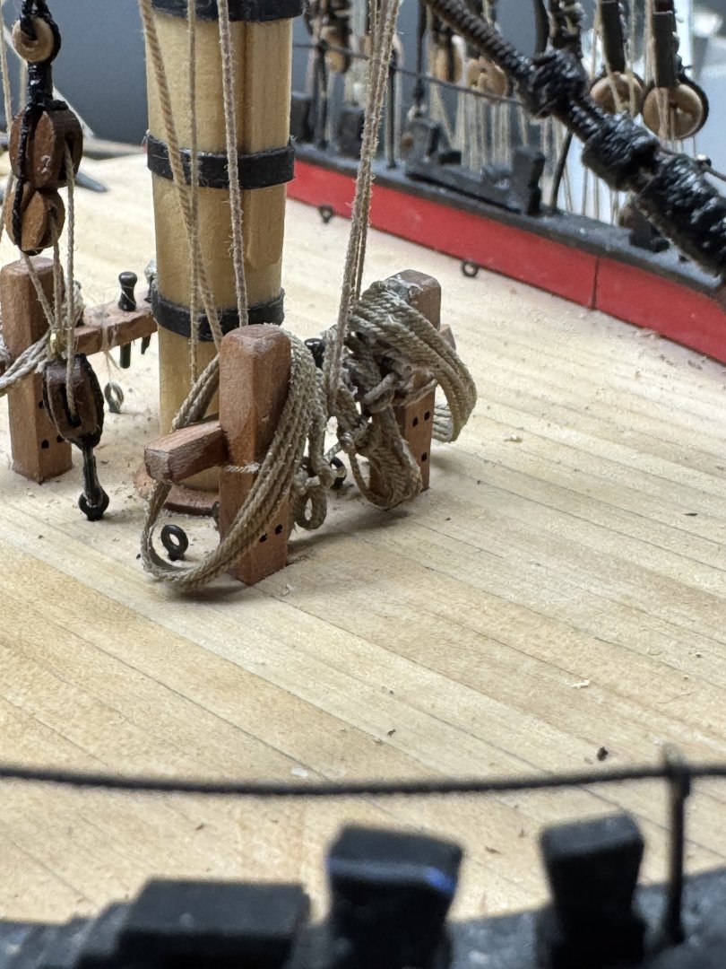
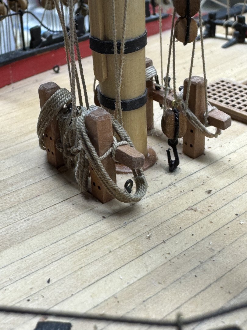
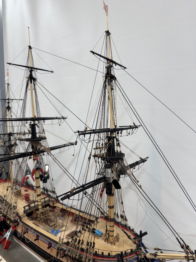
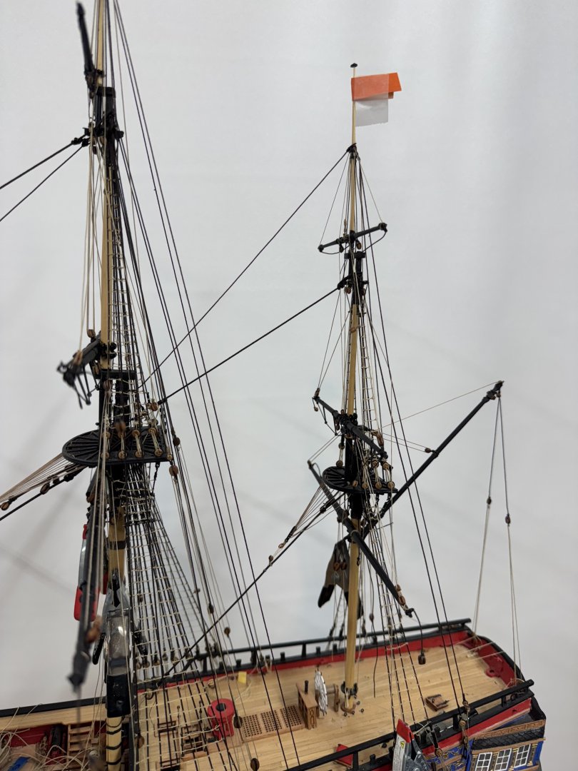
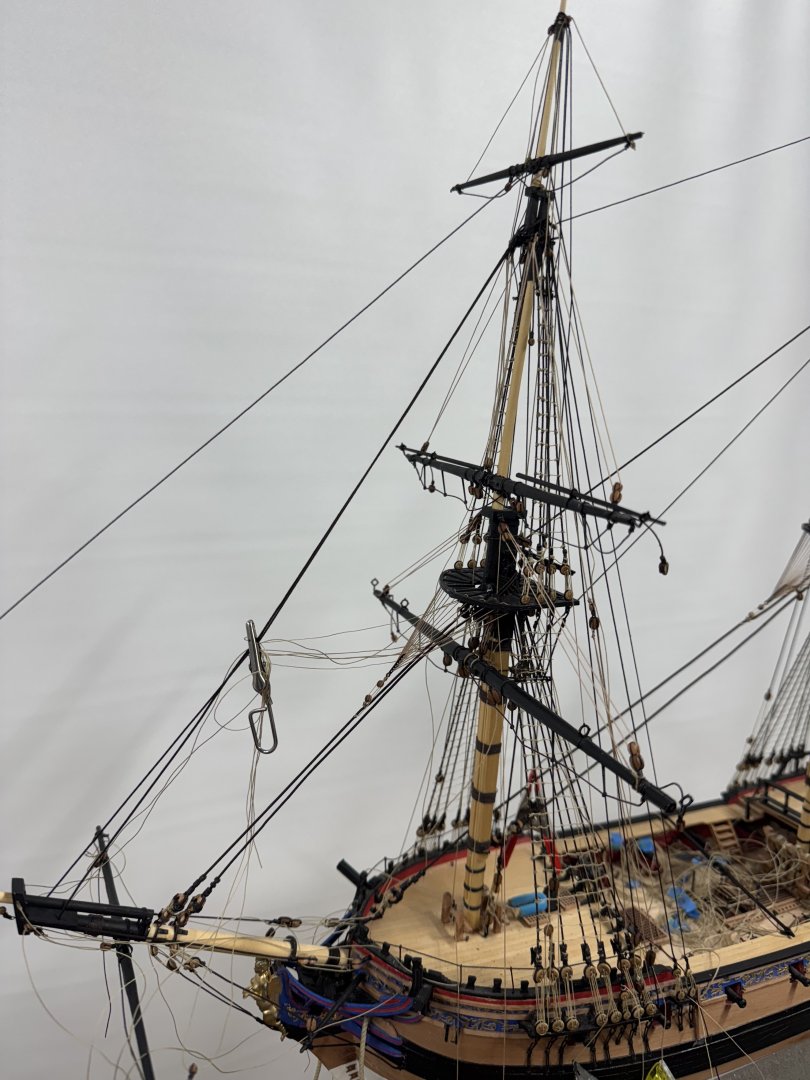
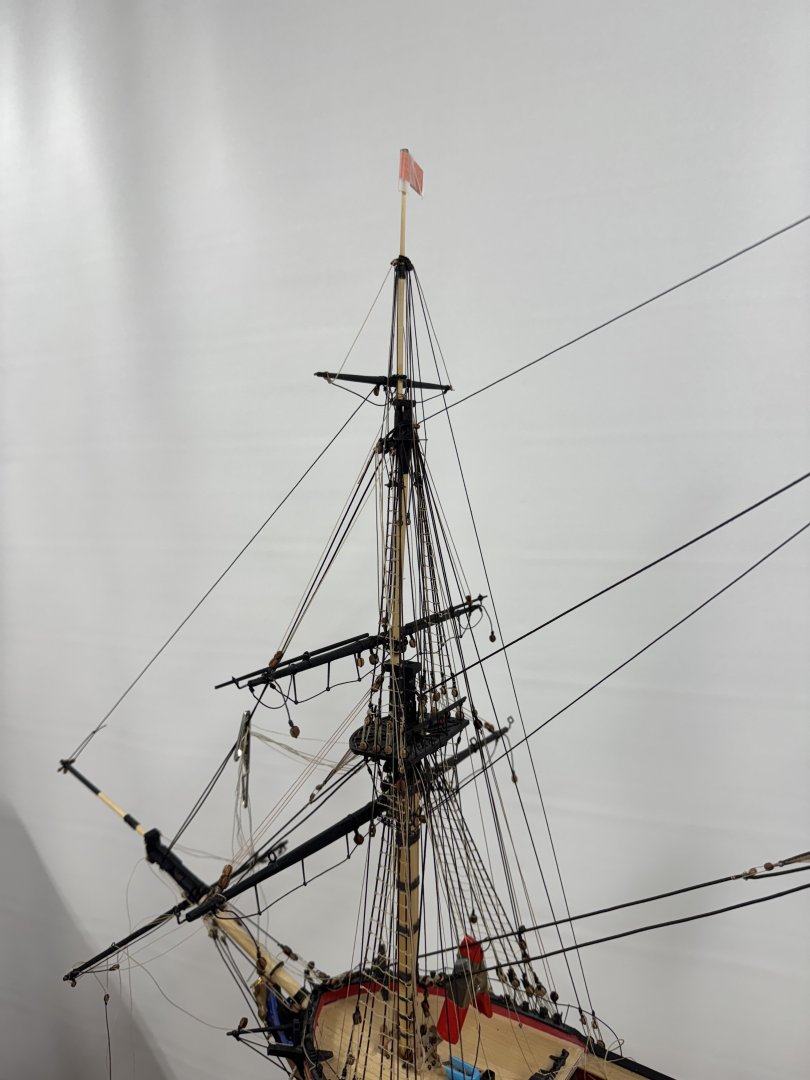
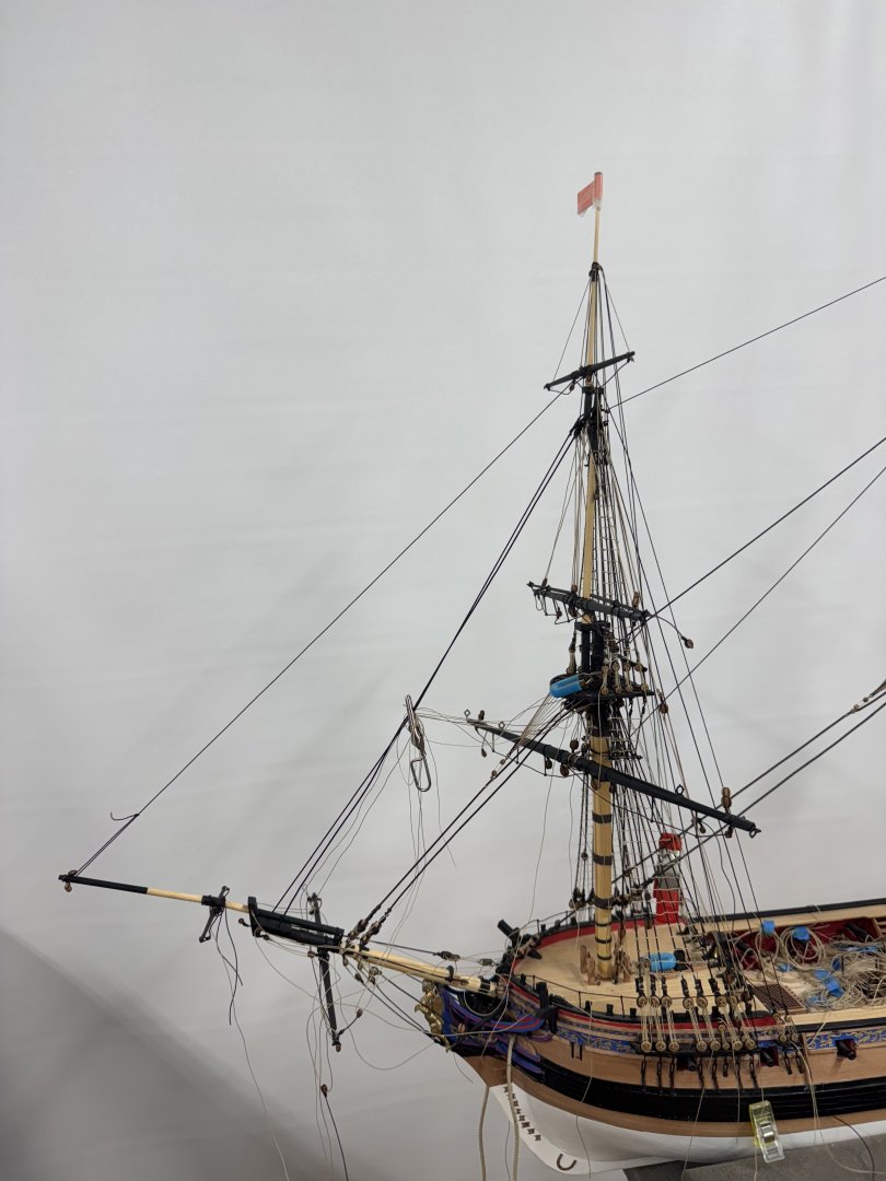
 I am still "toying" with the idea of planking the deck "the old fashioned way but I need to lay in a supply of whatever wood I decide to use if I go that way. I have enough boxwood (I think) but it is 3/64" instead of 1/16" I am n ot sure the lost 1/64" would be noticeable (since it would only be at the outboard edge but it would make getting the timberheads installed since that is exactly where they would go. So to make planking a possibility I test mounted the hull in the Amait carrier and drilled the holes for the fore and main masts using the 25/64" bit as recommended.m I actually HAD a 25/64" bit much to my amazement and it appeared to be in original condition. I am waiting for Amazon to deliver my new white paint before I can start painting white on the spars so I started to look at the boom rests. The instructions say to use 1/8" stock and drill the appropriate sized hole (3/8 or 5/16) and then file/sand to round. Having tried to drill big holes in soft wood (with generally unsatisfactory results) I decided to make my own plywood from two pieces of 1/16" boxwood and then "follow the instructions." Here is the fore mast boom rest and example of the starting point. Getting the 3/8" hole in the center of the marked outer perimeter was not as easy as I had hoped. The fore boom rest is on the mast while I add the supports. I have scotch tape on the mast so the boom rest can be removed when all four supports are in place. I have hopes of putting furled sails on all the masts so the boom rests will come "later".
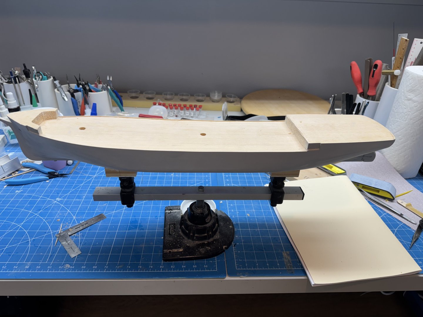
- 121 replies
-
- 6
-

-
- Lucia A Simpson
- AJ Fisher
- (and 1 more)
-
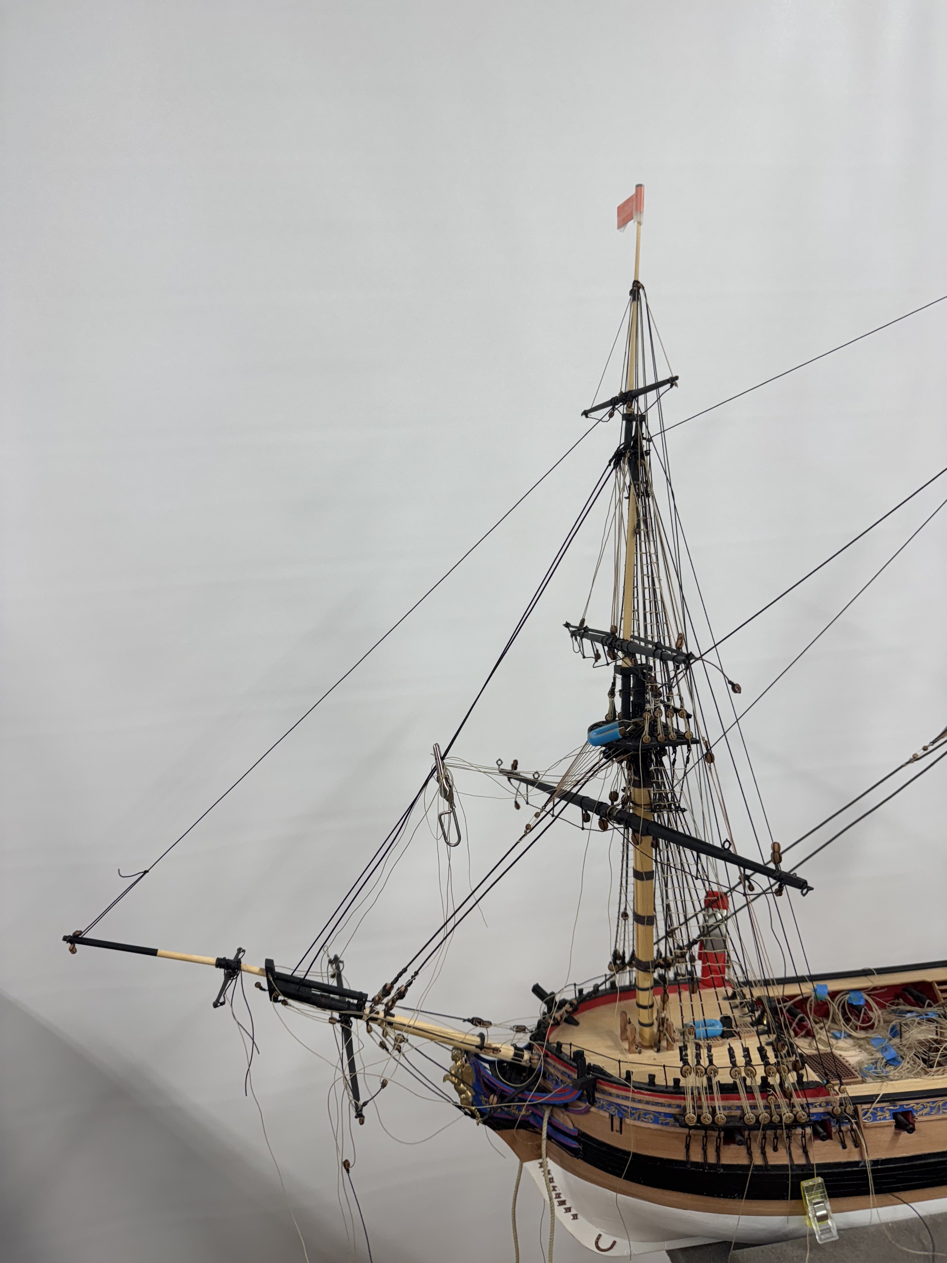
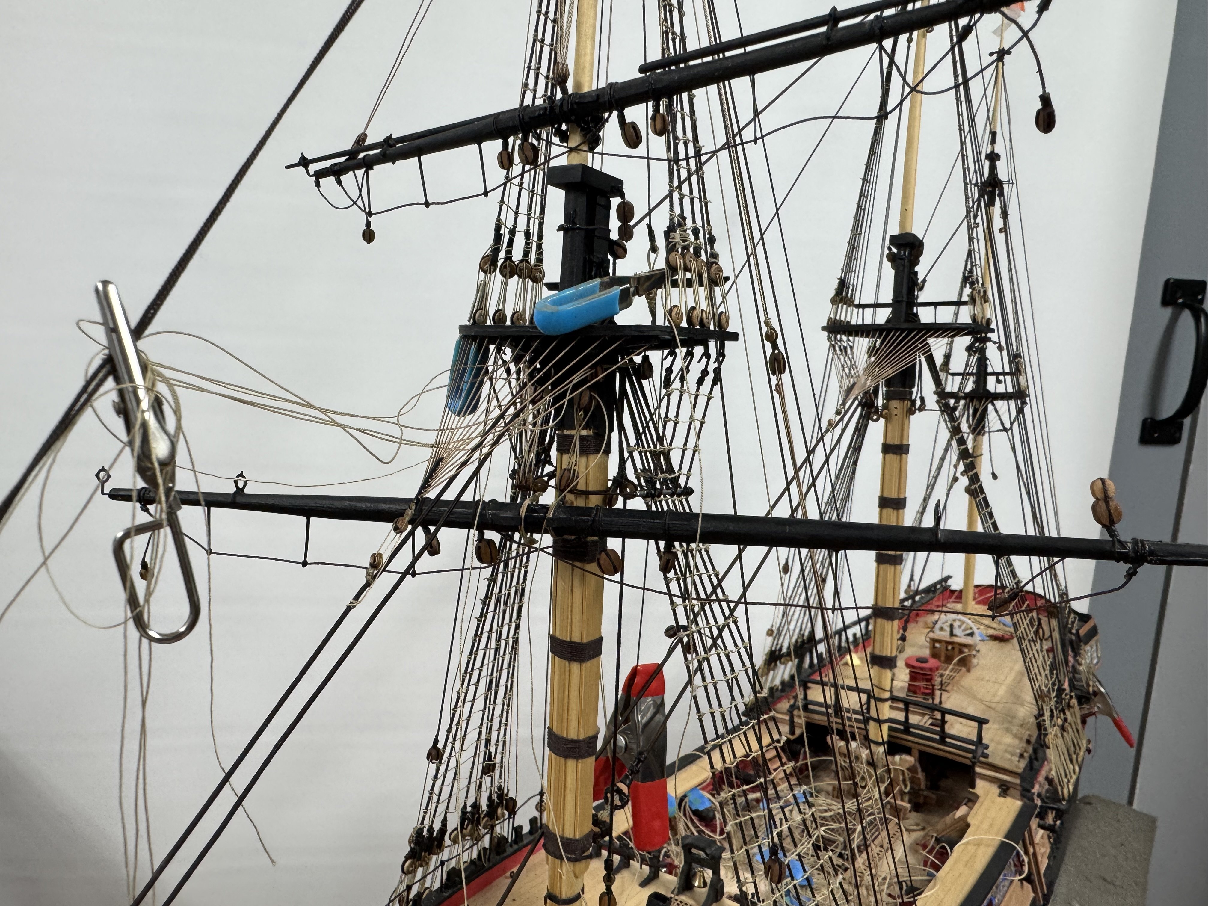
Thanks Rick. I have the last coat of Wipe-on-Poly on the spars now. Next step is to get the cheeks added to the lower masts and start painting white. Speaking of white paint - there will be a considerable amount of white going forward so I took a look at my white paint inventory. I have a 17ml "bottle " of both the Vallejo 70-951 "white" and the 70-919 "cold white" neither of which is likely to be enough to paint all that needs painting. I tried ordering more of either but the prices (~ $7.00 for one "bottle" plus a delivery charge) were out of sight (can't be tariffs yet?) so instead I ordered the Vallejo "Premium Color" White (62.001) which comes 60ml to a bottle (I ordered 2 - they will be here tomorrow (4/5)) so that should be all the white I will need. Here are the spars now "ready for action" Not easy to see much difference from the last picture but trust me they are all getting smoother with each additional sanding and coat of WoP. I also have the hull ready for it first coat of grey filler/primer. The sharp eyed can see several screw heads showing in the keel. I am building some jigs to allow me to use my Amati "holder" to host the hull once it is ready. I need to make sure the keel is "well and truly laid" as they say and will not pull off the hull since the "tabs" that will mate with the Amati holder are attached to the keel (and hopefully through to the hull as well). I got all the boom and gaff jaws "completed" (aka the bolt heads installed and belaying pin holes drilled).

- 121 replies
-
- 5
-
-
- Lucia A Simpson
- AJ Fisher
- (and 1 more)
-
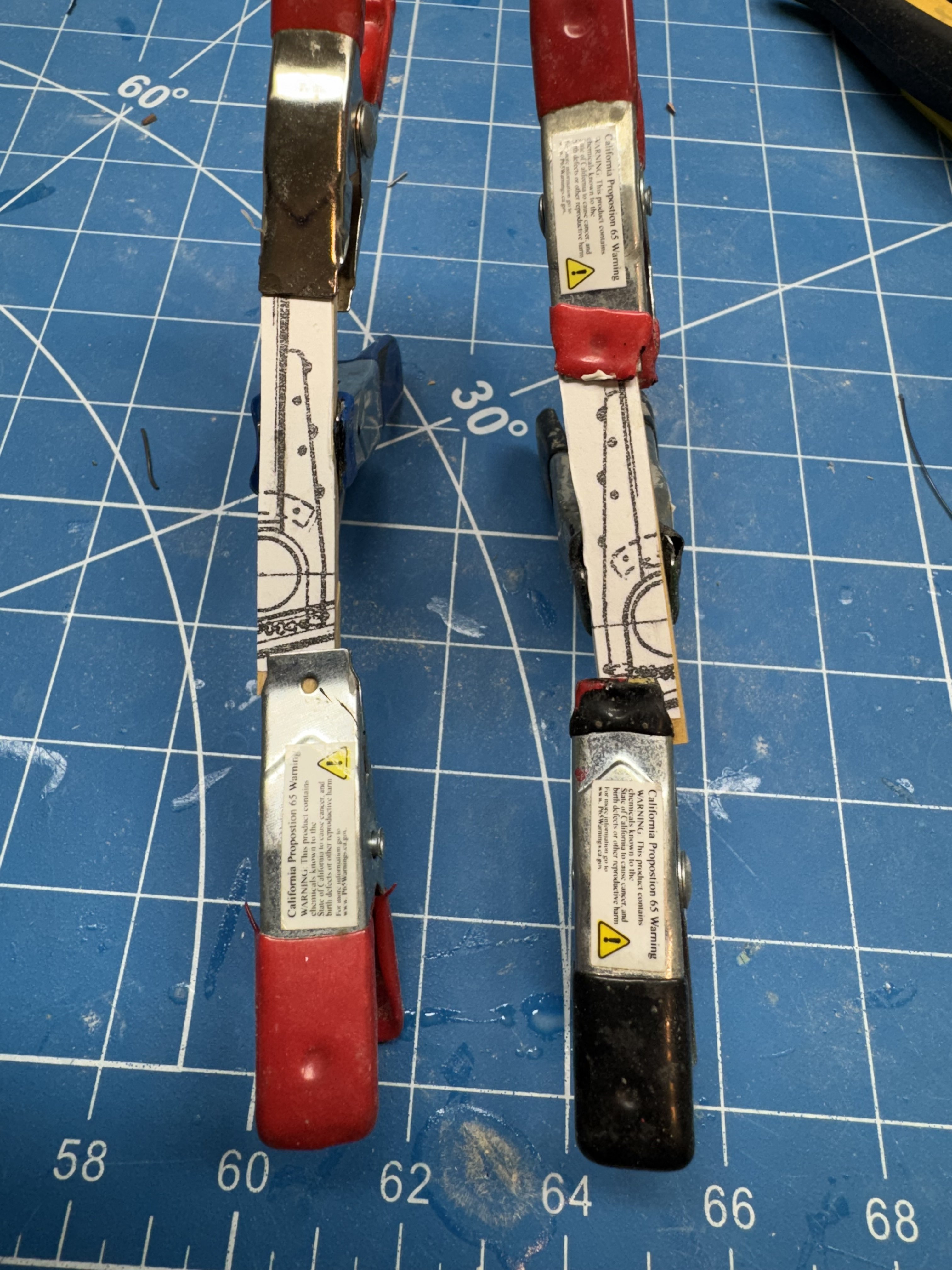
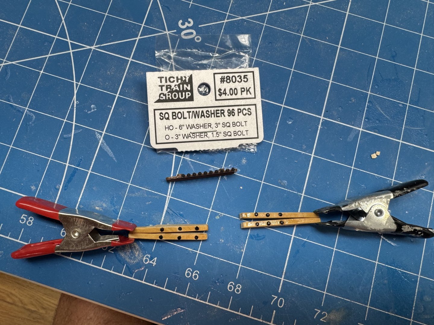
I mentioned previously that I was going to use box wood instead of the supplied basswood for the boom and gaff jaws. I used the previously mentioned technique (it sounds better than scheme) of gluing the jaw outline to a piece of boxwood that is actually two pieces glued together. The disc sander does a good job of shaping both pieces at once with only a minimum of hand work afterwords. Turns out, if left overnight 70% isopropyl alcohol will weaken the PVA glue joint enough to easily pry the two pieces apart. So now I have the jaws for the fore and main booms. The drawing shows three bolts on each side used to attach the jaws to the boom. I would guess that by 1875 iron working was reasonably advanced and they probably had large square (maybe hex) headed screws (or maybe bolts) to attach the jaws. Rather than use steel wire or monofilament fishing line (I have used both) to simulate the bolts I used some small, plastic bolt heads I happened to have on hand. Here are the first two sets of jaws with the bolt heads in place. I had to drill the holes larger than technically necessary because there is a very short "stem" on the bolt and getting them in a smaller (I used #66 drill) was very difficult (for me). I used a small. hammer to tape the bolts in and then brushed on some WoP to act as a sort of glue. Hopefully the bolts will survive installation on the boom. I am going to take these two sets "all the way" to boom installation before committing this method to the other four sets of jaws. Speaking of the other jaws - the drawing does not have a plan view of any of the gaff jaws only the boom jaws. Luckily I noticed that the gaff jaws "horns" are 5mm longer than on the booms. This allows the boom to be at an angle to the mast. I had to extend the horns on my copies of the drawing to use them as templates for the gaff jaws. Just one more of the "little things" that make this kit not something for a beginner.
- 121 replies
-
- 6
-
-
- Lucia A Simpson
- AJ Fisher
- (and 1 more)
-
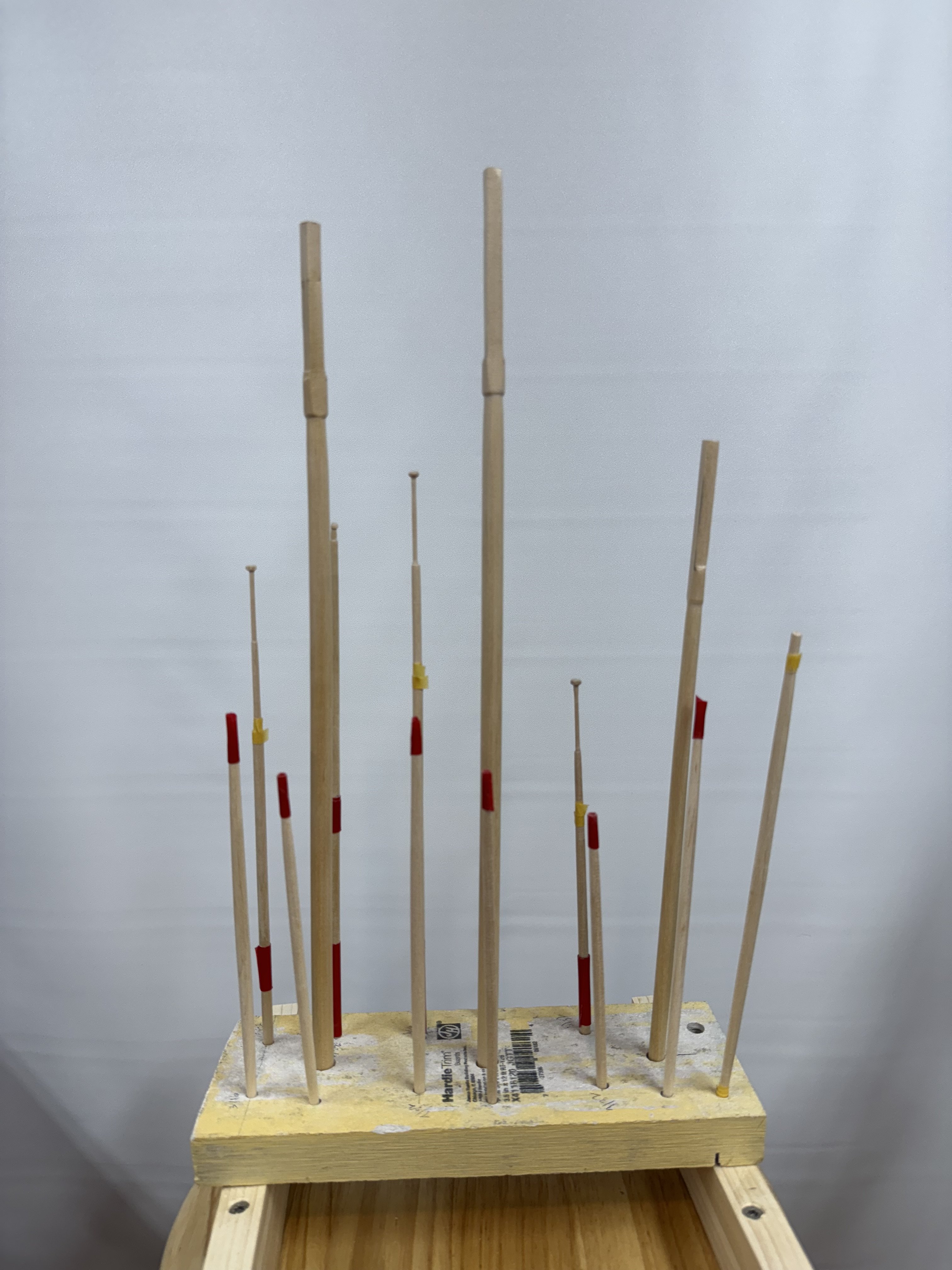
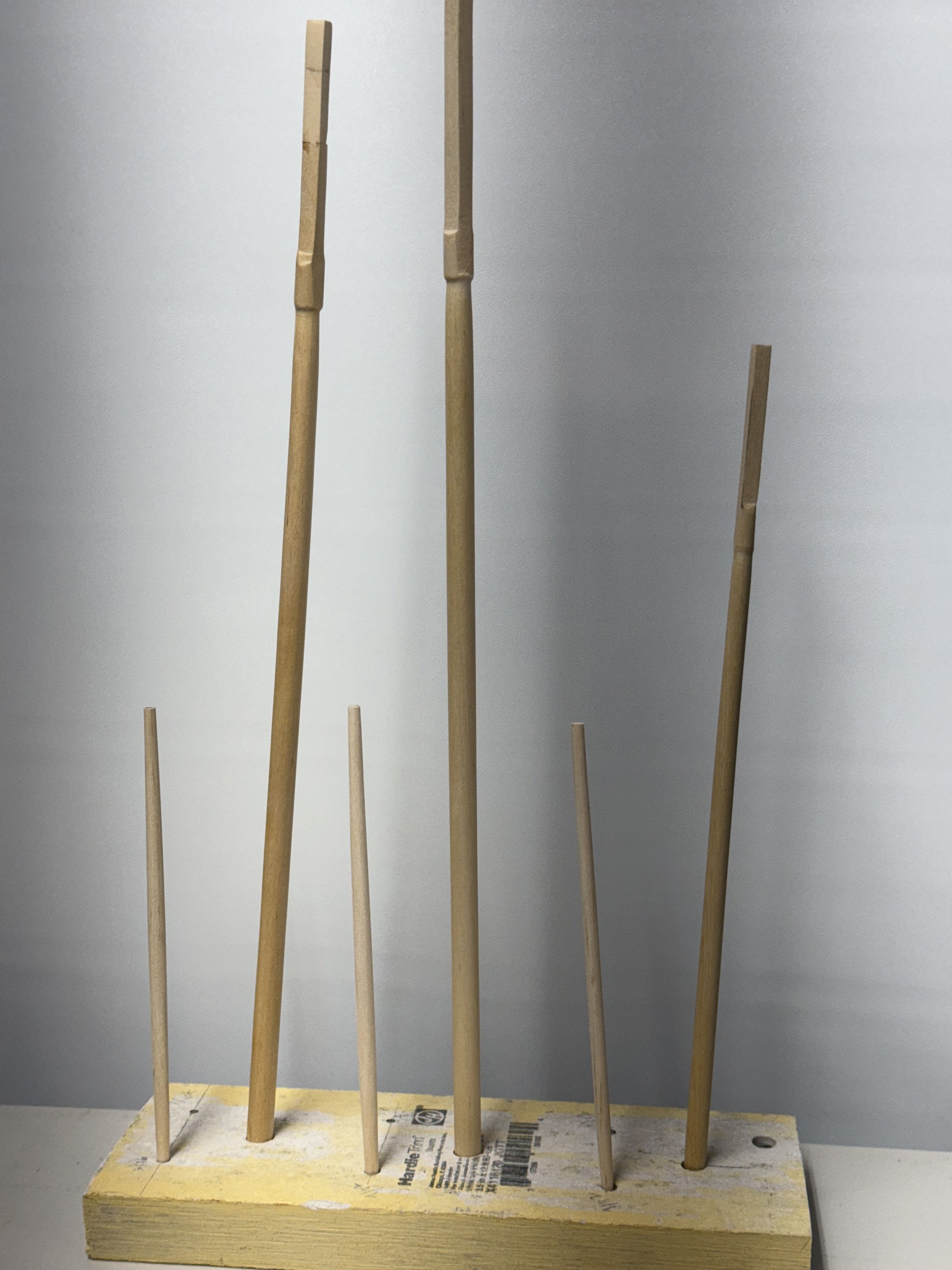
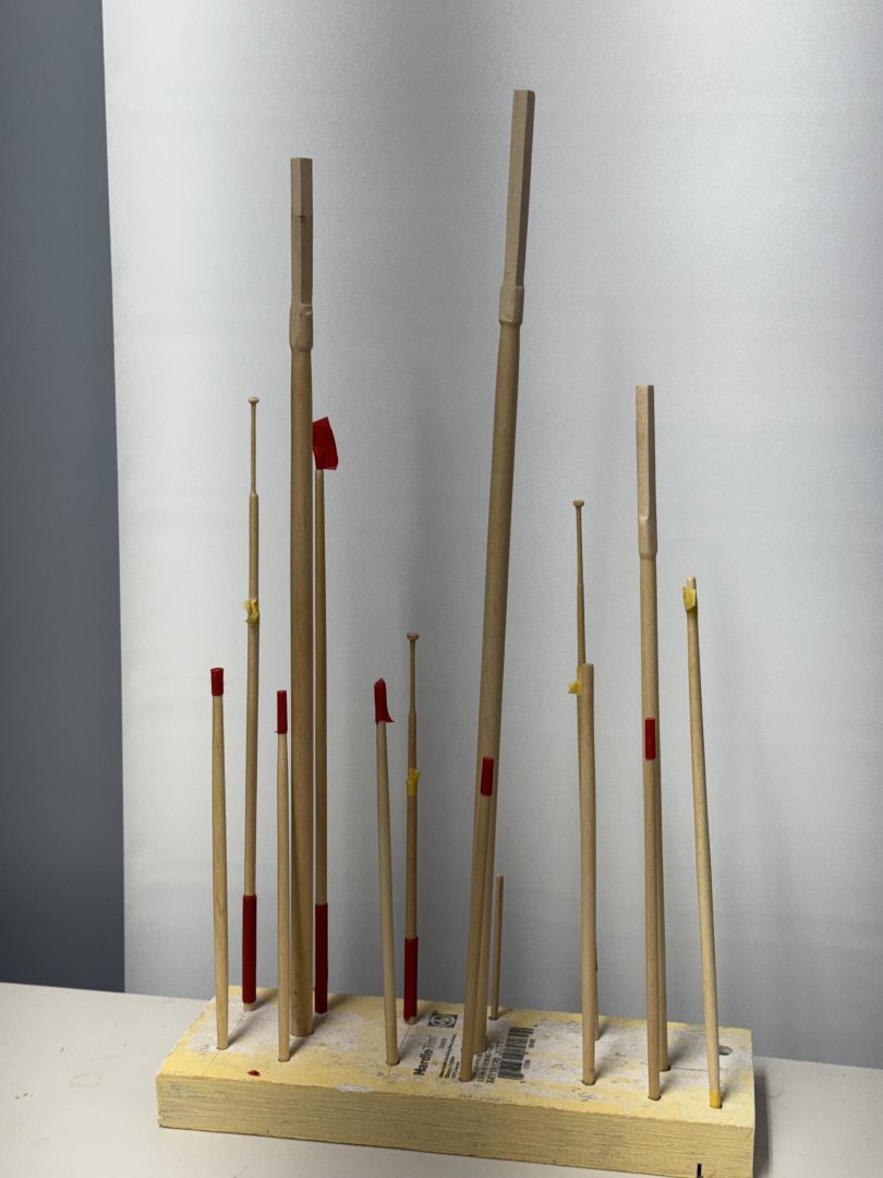
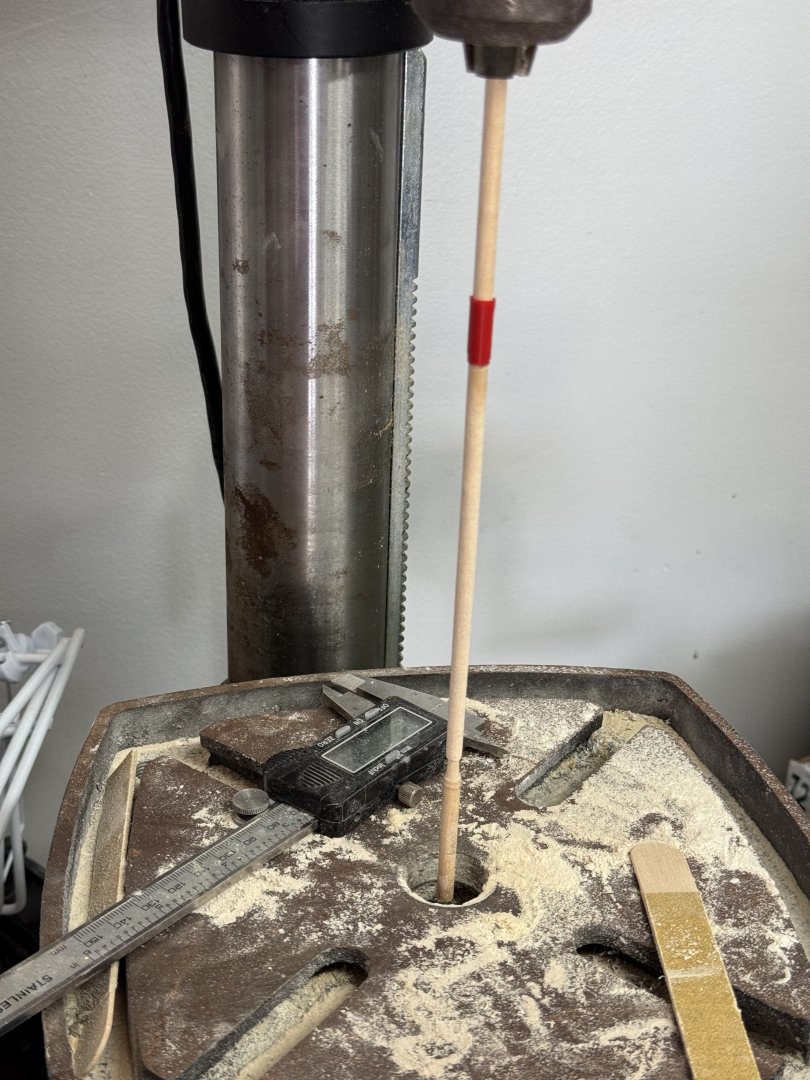
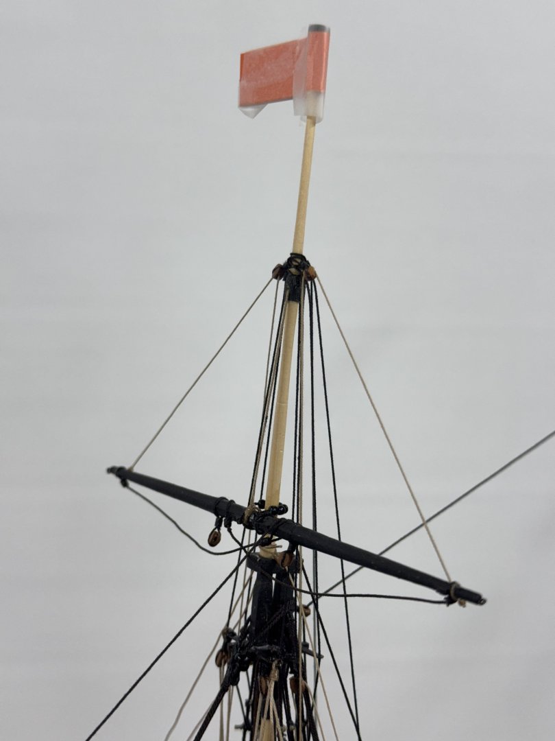
Today was "spar" day. I got all the gaffs, booms, yards and such completed. The top masts were the hardest. The very top segment is 1/16" diameter the entire length and then there is a "gilt truck" on the very top. I spent almost an entire hour last night creating that segment on the fore top mast and figured there must be a easier way to reduce the 3/16" diameter dowel to 1/16". I have a desk top drill press that I have used on occasion to turn masts but never anything this delicate. It works best when there is plenty of extra length in the dowel as chucking the dowel in the drill press will usually mess up the part in the jaws. When necessary I used masking tape on the portion in the jaws if it was needed to get the spar the correct length but that is a last resort as it can make the dowel kinda wobbly which is not good - it leads to the dowel snapping off (don't ask me how I know. Here is a spar (probably not a top mast - (I think this is the jib boom) chucked up in the drill press with the table adjusted so a small portion of the dowel in inside the table opening. I put my left hand on the bottom end of the dowel to keep it steady and used an 80 grit sanding stick to take material off the dowel as the drill press turned at about 1500 rpm. I still had to be really careful with the top masts and rather than going all the way to 1/16" I stopped between 3/32" and 5/64" and then finished off with 220 grit by hand. It still took all day to get the other two top masts, three booms, three gaffs, the foremast topsail yard, the jib boom and the staysail boom ready for varnish (and then paint). The tape you see in the picture below is to keep the varnish (Wipe-on-Poly warm satin) off the areas that will be painted white.

- 121 replies
-
- 7
-
-
- Lucia A Simpson
- AJ Fisher
- (and 1 more)
-
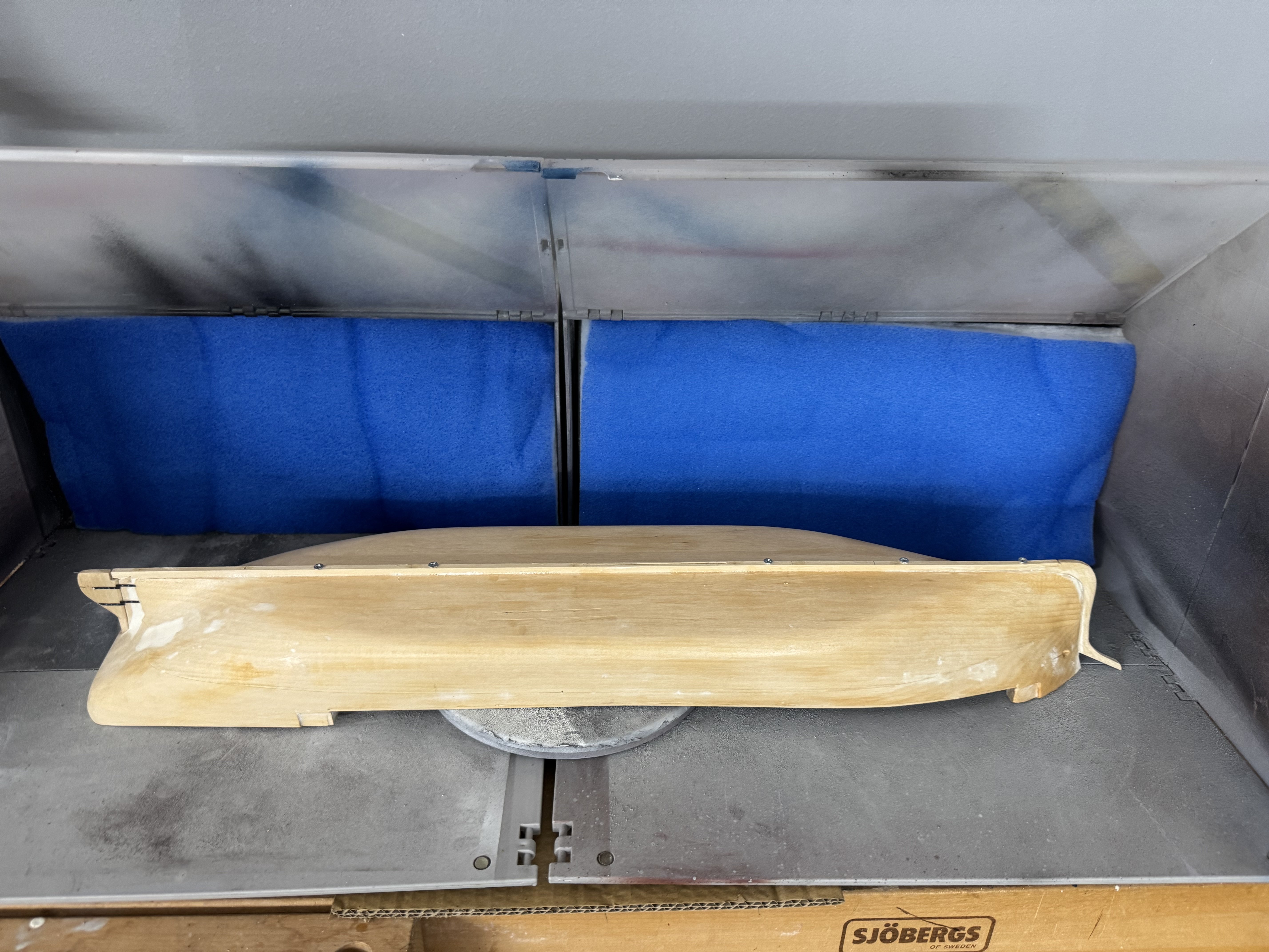
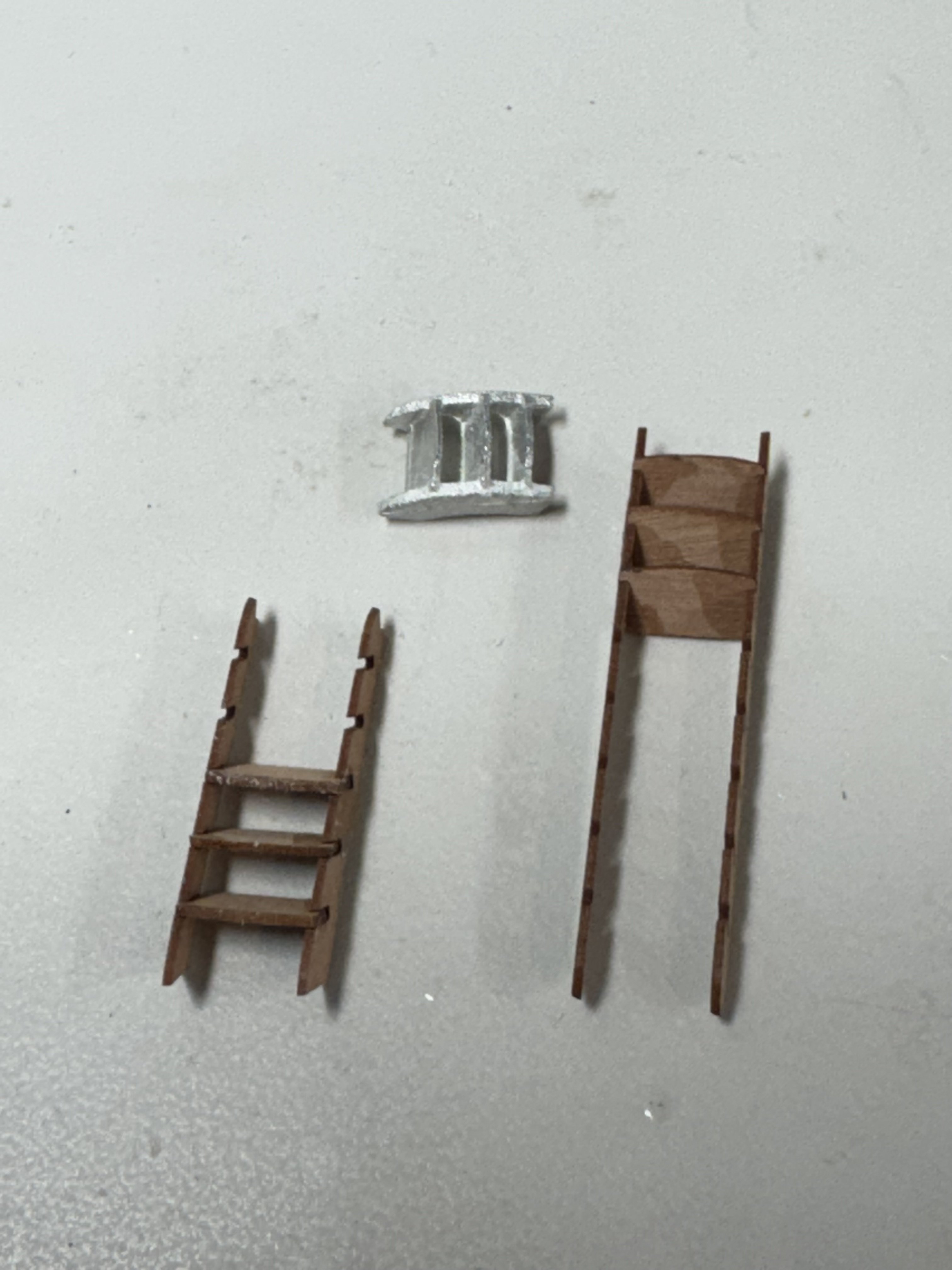
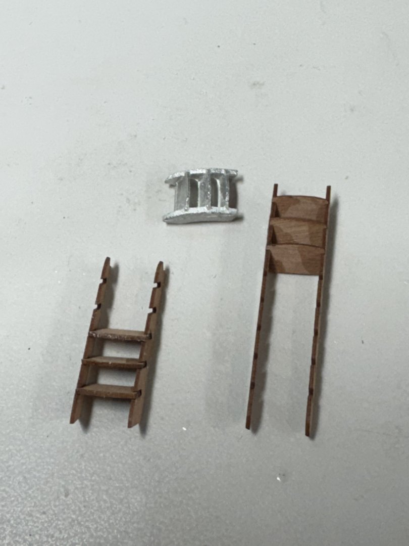
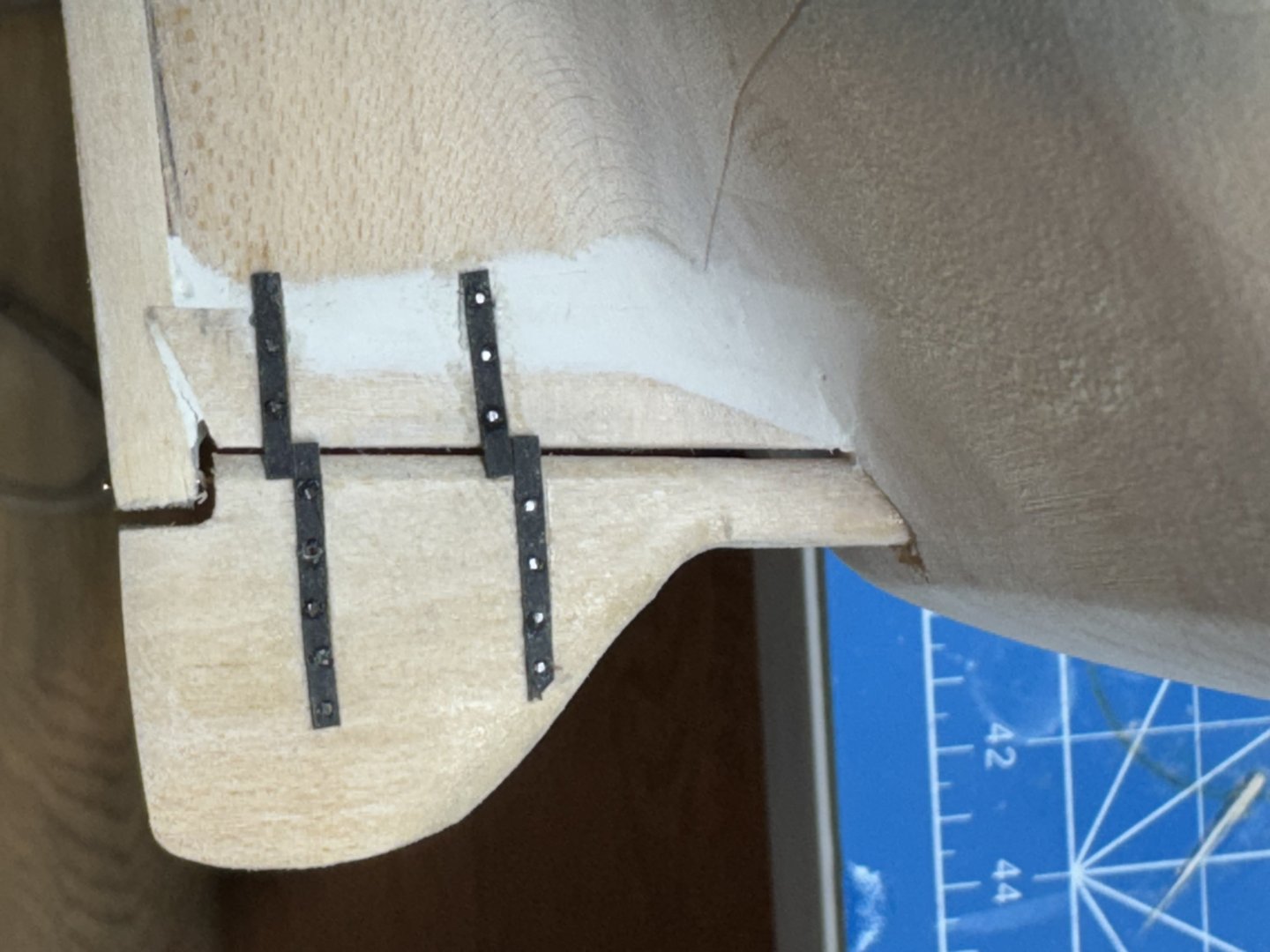
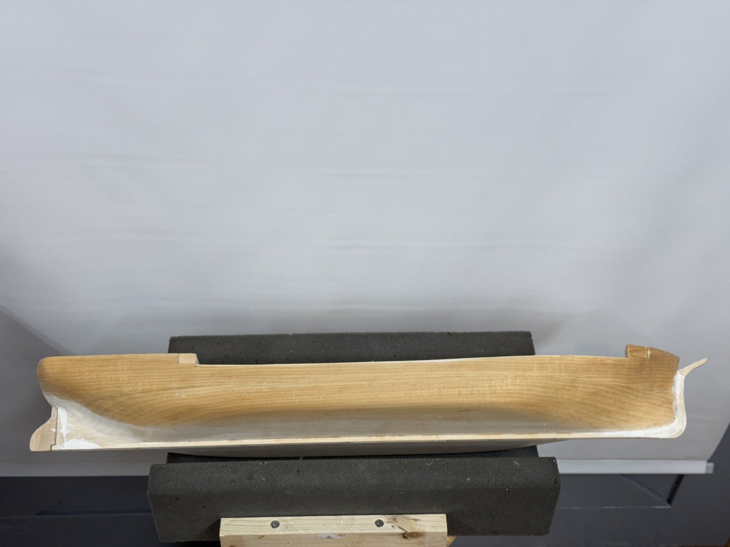
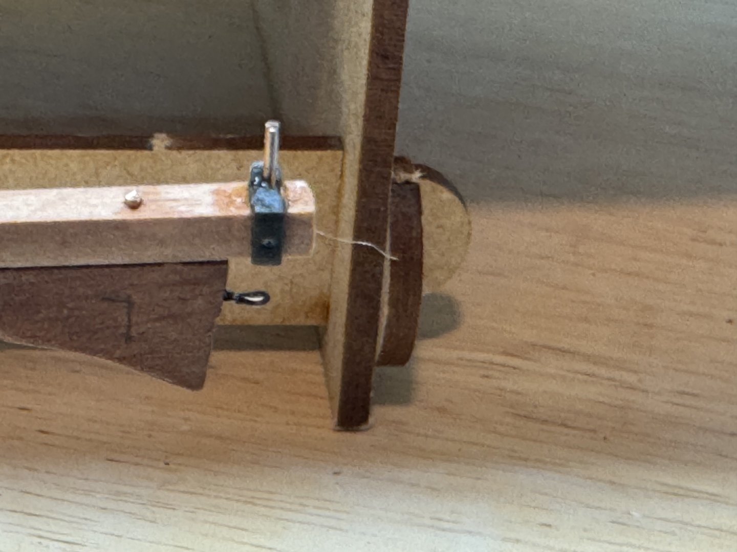
I have been "at it" for the better part of three days now. Unfortunately I seem to be "all over the place" doing a bit here and there without any noticeable "real" progress. First the hull - I sanded it down per the instructions fabbed the stem and stern post and added them along with the keel. I also refashioned the stern in accordance with the drawing. I am not sure why the "carving machine" did not do it but it is done now - more or less.I mixed up so Good Filla (from the bag of dry) and applied it liberally to the joints on the stem and stern post to cover up the small (IMHO) gaps that my imperfect technique let between them and the hull. That is still in process. I noticed a seam between the two pieces of wood that were apparently glued together to form the block that was fed into the carving machine. I do not know if it will show through after the sanding sealer but decided not to take a chance and mixed up some pretty runny filler and spread it over the joint on the port side, let it dry, sanded it off and wiped the hull down with mineral spirits. Here is what it look like now. (please ignore the unsanded filler at the bow and stern). I also fabbed the rudder and installed it. I looked at the rudder supports supplied with the kit and determined that I had placed the rudder to close to the stern post to use them. My bad but in my defense if I move the rudder any further back the rudder post will be very close to the stern/transom seam. So I rummaged around in the parts locker and found some Syren hardware and used that instead. Here is the rudder on the starboard side. As you can see above the port side is "next". The difference in the "bolts" seems to be what clippers I used since they were different between the top and bottom set. It won't matter as they will all be painted green. I fabbed the three lower masts and booms. Although they are not all cut to the required lengths yet they being prepared for paint/varnish before adding the "hardware". The three lower masts have one coat of ipe on Poly satin - the booms are unfinished. The sharp eyed will notice a seam in the lower foremast (left most tall one) in the square section. As it turns out this will be under one of the mast bands so will not show (and the upper line marks where to cut it for length). I broke off the top section when I was tapering the lower mast with the squared section chucked in my drill press (poor mans lathe). I forgot to steady the mast when the drill press turned on and SNAP went the mast. I squared off the two pieces, center drilled both pieces and pinned them together clamped to a ruler to keep them straight and carefully dabbed on some medium CA. After looking at the material provided for the boom jaws I decided to switch to boxwood which I have some left over from some previous project. To try and make sure the two sides of each set are "identical" I glued the plan of the jaw to a appropriately sized same piece of boxwood and glued another piece of boxwood behind it. I plan on using my disc sander to get really close to the final shape and then finish off "by hand". When I am done I plan to soak the two pieces in isopropyl alcohol to break the glue bond. I have 99% isopropyl alcohol due here tomorrow (ain't Amazon useful?) since the 70% you can get at Walgreens is apparently much slower to act. Here are the jaws for the fore and main booms getting the glue dried. I found another issue with the kit - the mast coats provided are way too small for the main and fore masts which are 3/8" diameter at the deck (according to the drawing). I measured them and they are about .055" to small. They are probably 5/16" rather than 3/8". I have the correct size ordered from Bluejackets. I also decided I did not like to two cast metal stairs supplied. I had some remnant stairs left over from Sphinx that are narrow enough but way too long. Hopefully I can get them cut down and replace the metal ones which I think I would struggle to make look "good".


- 121 replies
-
- 7
-
-
- Lucia A Simpson
- AJ Fisher
- (and 1 more)
-
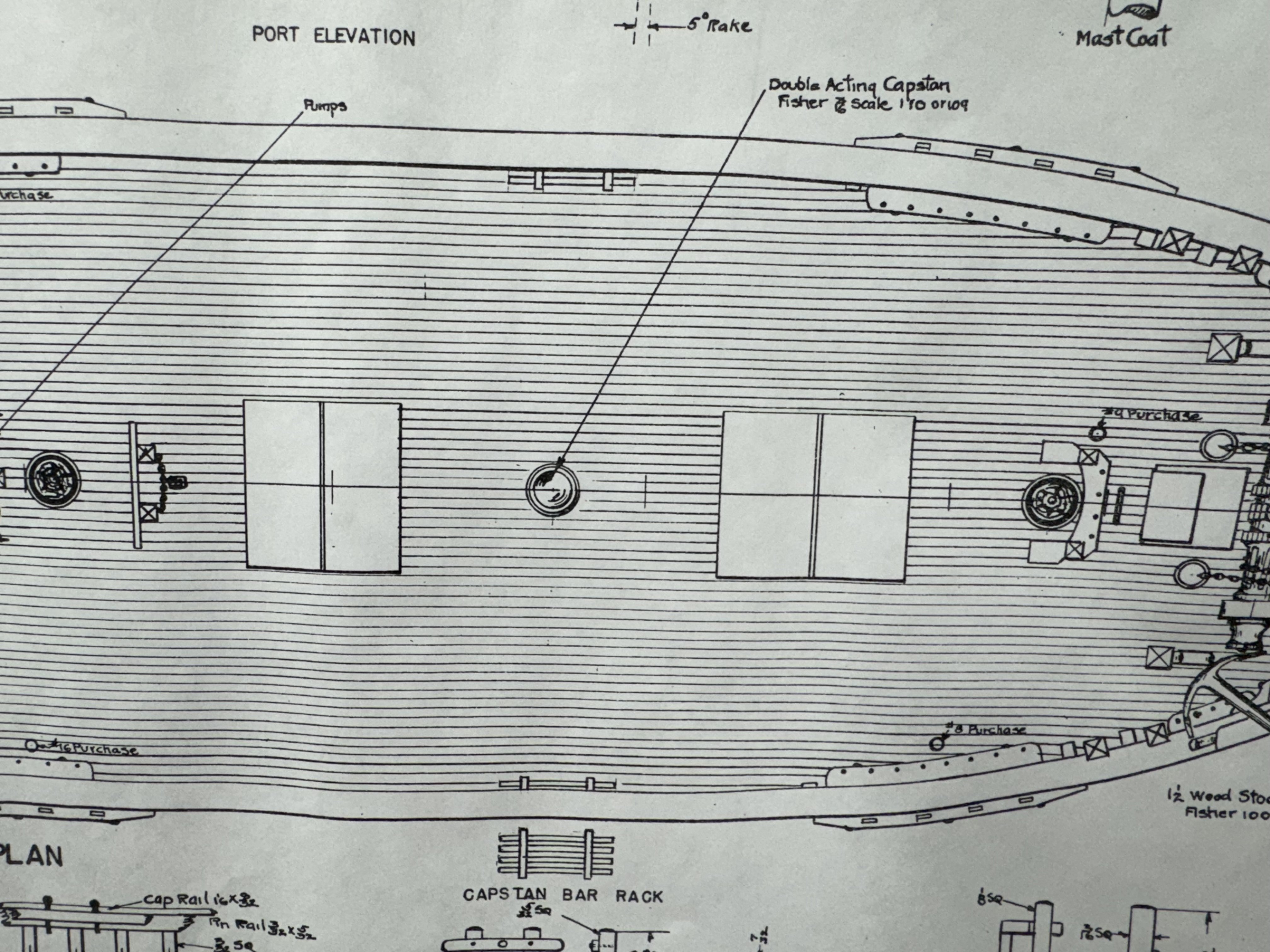
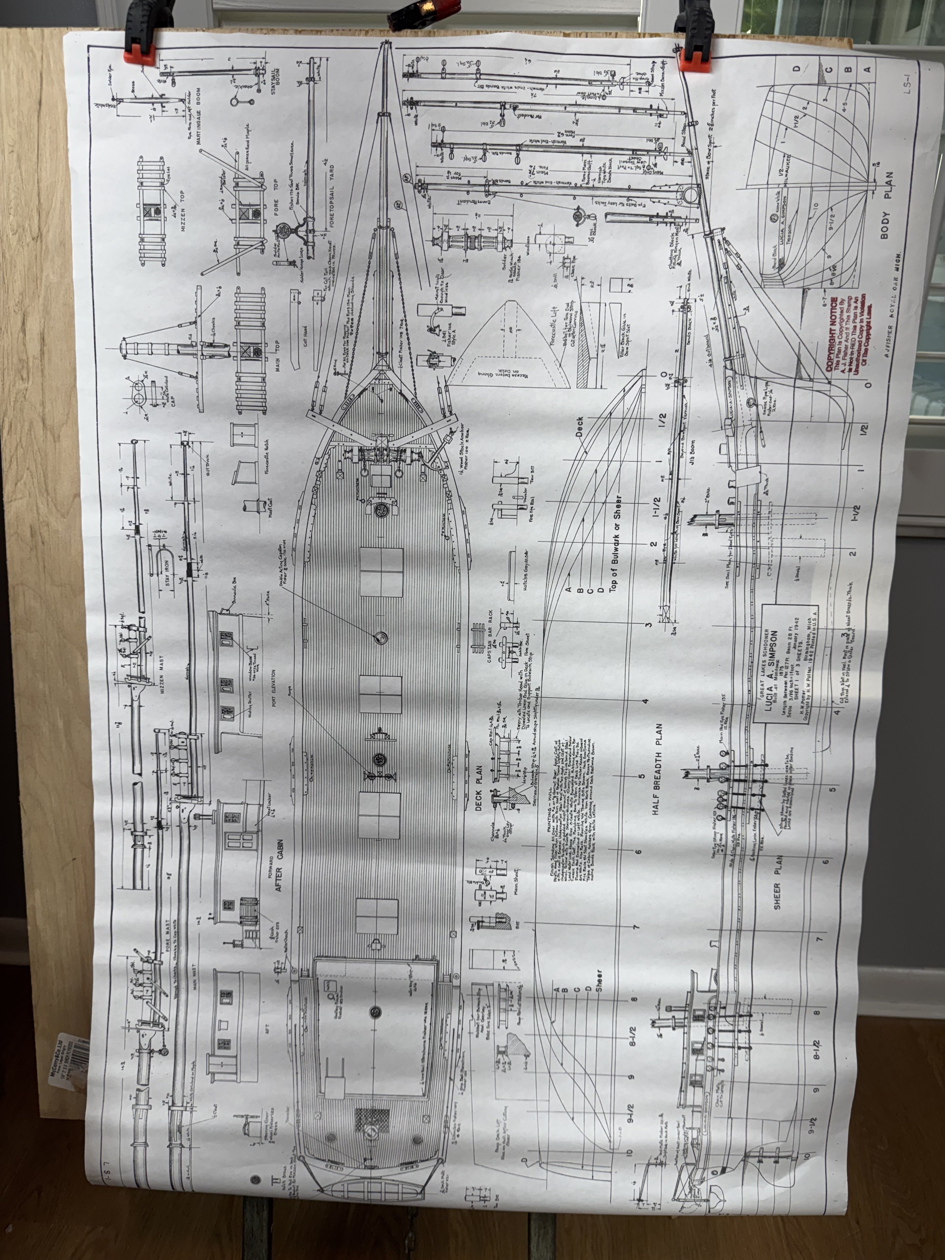
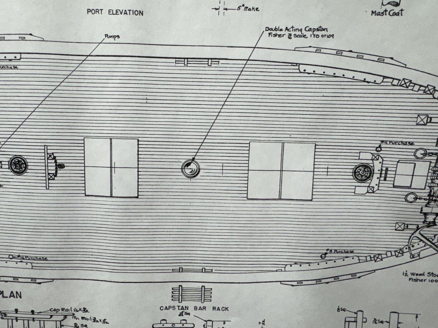
While waiting for glue to dry I studied the drawing (besides two sheets mostly dealing with rigging there is really only one sheet) to see what "things" were going to be needed that at least so far I have not found on the parts list or included with the parts. First item are turnbuckles - 8 required (four for jib boom stays, 2 for bowsprit stays and two for martingales). no mention in parts list or included. Second item - hatch coamings - there are four cargo hatches but all that is included are four 3/16" thick rectangles of various dimensions. Here are two of them on the drawing. Not much to go on and the instructions are almost silent on the subject "Glue the hatch covers on the hatch bases, seal and paint." No hatch covers are included or identified in the parts list. Third item - mast caps, 3 required. There is a drawing of one mast cap on the drawing but none supplied and no material identified to fab them on the parts list. And the drawing shows a mast cap with two round openings but what is needed has a square and round opening. I ordered an assortment of mast caps from Bluejackets as trying to fab them seems in the "too hard" pile since they appear to be readily available and I am generally lazy. I am beginning to get the idea that these kits have been sitting around for awhile - it got here (MA to FL) in 5 days so it must have been "on the shelf" or whoever is minding the store does not have much to do and all (or at least most) of the parts are "on the shelf".
- 121 replies
-
- 4
-
-
- Lucia A Simpson
- AJ Fisher
- (and 1 more)
-
The drawing shows how large to make the rabbet for the bulwark so I made all four. Here is one - I might add that basswood is not very good at holding a sharp edge. There appears to be some confusion (at least I am confused) about how large the bulwark should be and when it is installed. By my measurement it should be 7/16" but the drawing shows 9/16. That is the total height of the bulwark on the original hull but now there is a 1/16" piece on the hull which will be deck level and a 1/16" gap for the scupper slot soooo. I appears that the inner bulwark (that is what the instructions call this but as far as I can tell it is the only bulwark) cannot be installed until the timberheads are there to give it the proper shape and those come after the decking is installed. At this point I am ready to put the sanding sealer on the hull and see what "issues" remain before installing the keel, stem and stern post which are the next steps in the instructions.
- 121 replies
-
- 6
-
-
- Lucia A Simpson
- AJ Fisher
- (and 1 more)
-
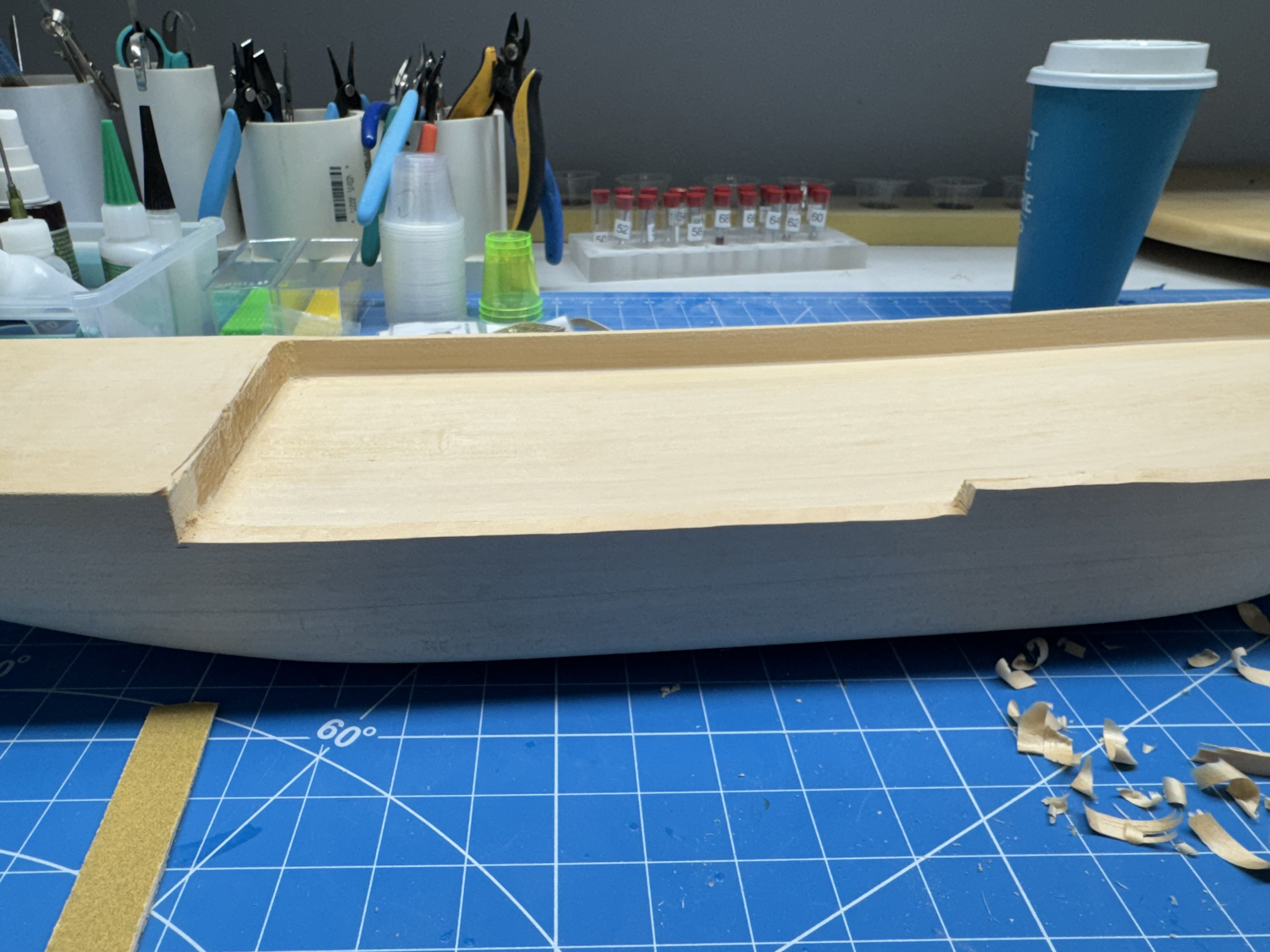
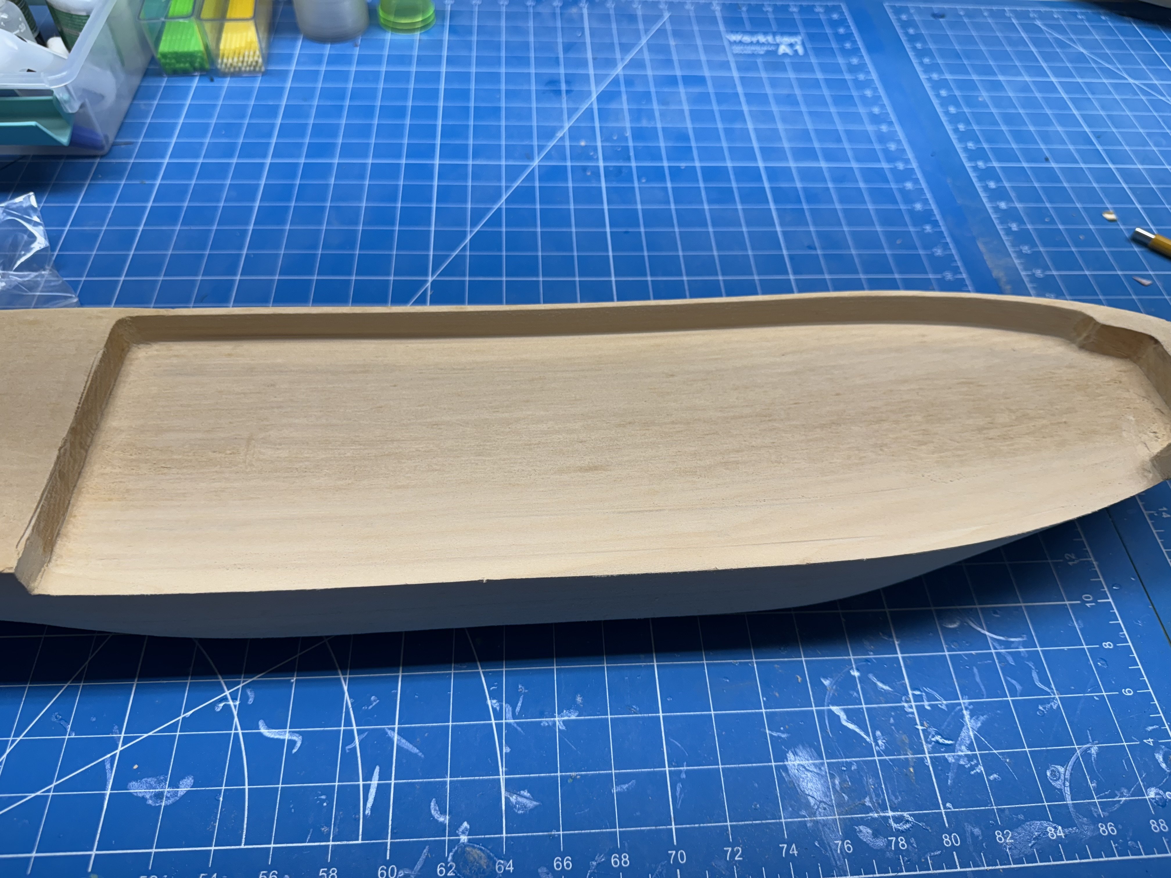
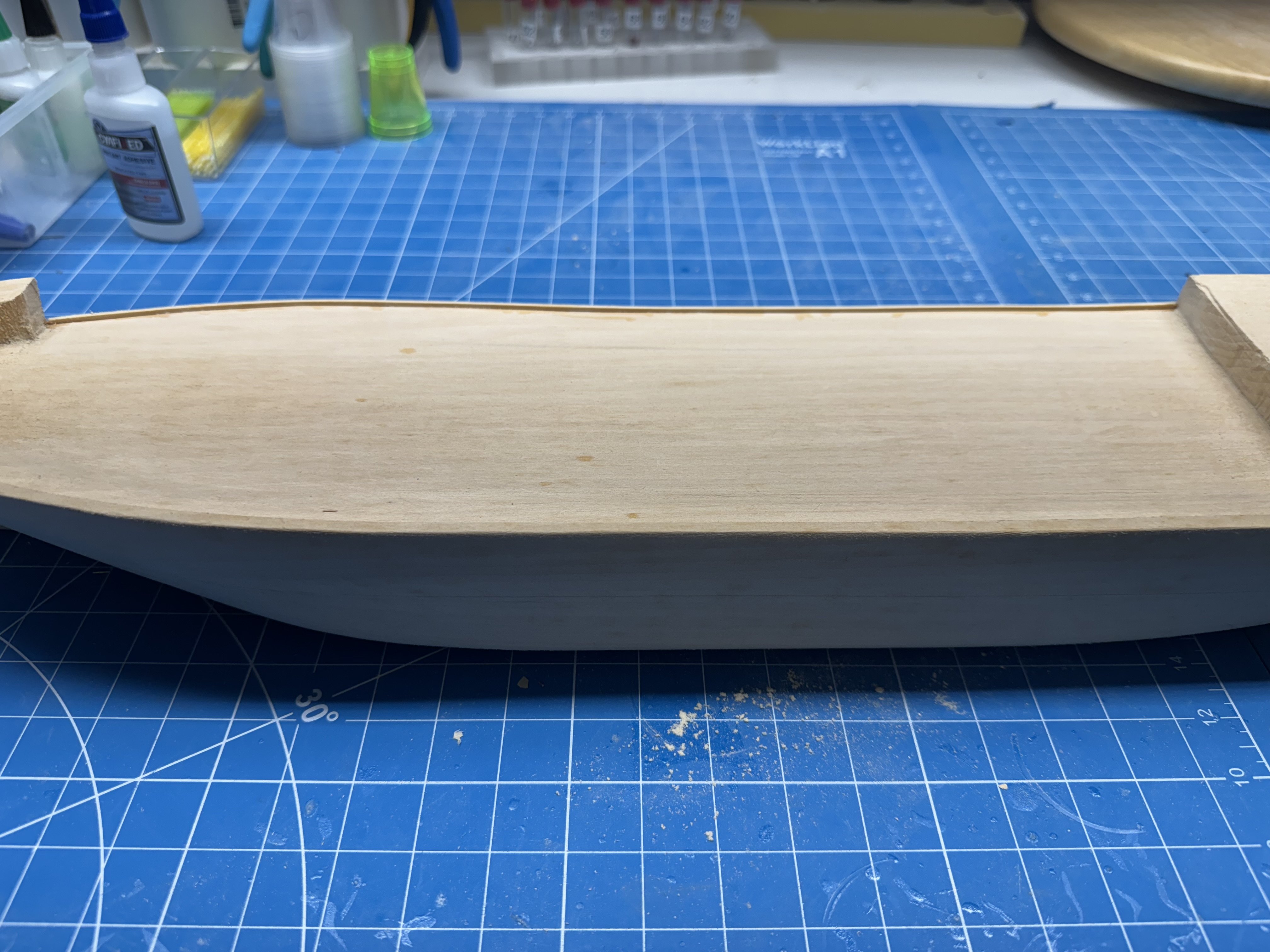
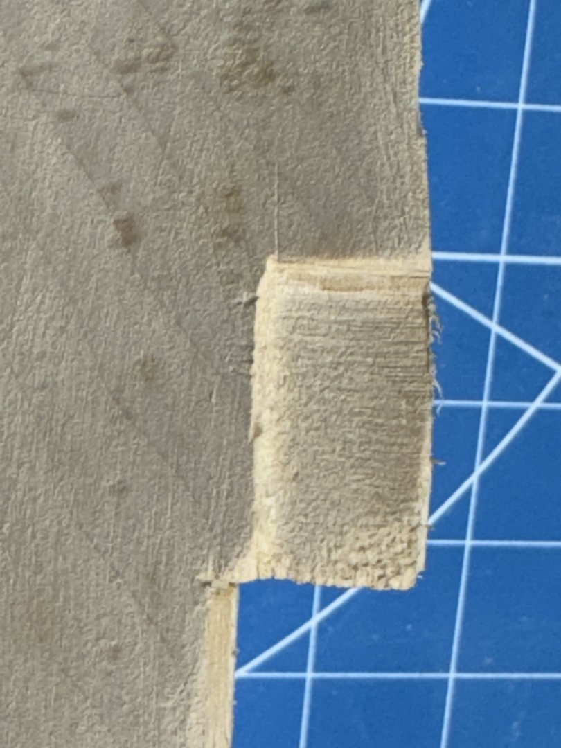
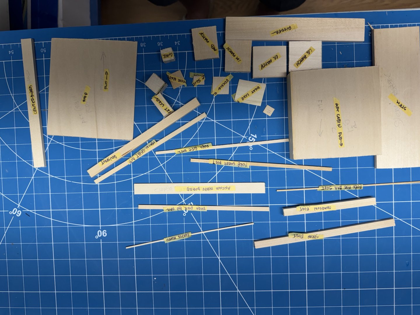
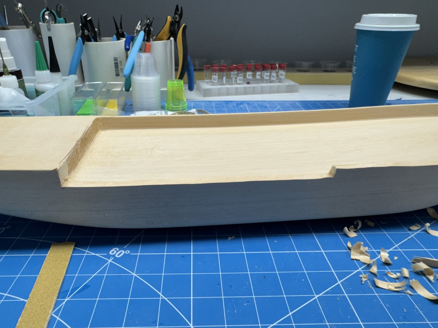
Given that the kit included a "bag of pieces' I thought it prudent to see if all the pieces listed on the parts list were included. I concentrated on the bag with pieces 6" or shorter. I have plenty of basswood pieces if one or more of the 24" pieces is missing or (heaven forbid) gets damaged during construction. Since I would have to "mark them off the list" I thought it a good idea to identify them for ease later on. and indeed everything is accounted for. On to the preformed hull. The instructions say to sand the entire hull exterior with medium then fine grade sandpaper paying attention to the rudder skeg and stem to reduce them to 3/16" to match the keel dimensions. That was not too difficult as there were only a few "blips" where the machine left a dimple that had to be sanded out. In my dream last night I actually thought about actually planking the hull. It would be an interesting activity as the curve at the bilge is much sharper than anything I have attempted before. I will have to think about that some more. Now to the inside of the hull. Although the instruction say that the bulwarks are 3/16" thick I found them to be a bit thicker - more like 1/4". The instructions offer two options - 1) sand the bulwarks down to 1/16" thick and then cut a 1/16" slot from one end to the other for the scuppers. Wow - that sounds like a lot of work and I doubt I could make a thin slot like that look acceptable. 2) Draw a line 1/16" above the deck and remove the bulwarks down to that line (after sanding them to 1/16' thickness), cut a rabbet in the hull just outside the focsle and poop and install a new 1/16" thick bulwark leaving a 1/16" slot above the remaining 1/16" bulwark for the scuppers. I thought it would be easier (for me) to cut the bulwark down (no sanding required) all the way to the existing deck level and the add a 1/16" X 1/16" strip to form the outer edge of the decking (which I also considering doing the "old fashioned way"). It adds another "joint" on the hull but I doubt I could leave a consistent 1/16" "lip" while removing everything above. Here is the hull with one half of one side bulwark removed. One side completely removed. And with the "filler strip" added. On to the other side with a bit less trepidation.


- 121 replies
-
- 7
-
-
- Lucia A Simpson
- AJ Fisher
- (and 1 more)
-
I was not very good at math - indeed the kit is 1/64th scale which will make it easier to substitute a Vanguard 3D printed life boat instead of making one starting with a rectangular block of wood as the instructions suggest. Although I did not specifically point it out the kit contains ZERO laser cut pieces (except for the laser engraved deck planking sheets). Quite a contrast to the Vanguard HMS Sphinx which I just finished which (except for the hull planking) had ZERO strip wood pieces. I guess I will be doing it "the old fashioned way" to quote an old commercial from Smith Barney (I think).
- 121 replies
-
- 4
-
-
- Lucia A Simpson
- AJ Fisher
- (and 1 more)
-
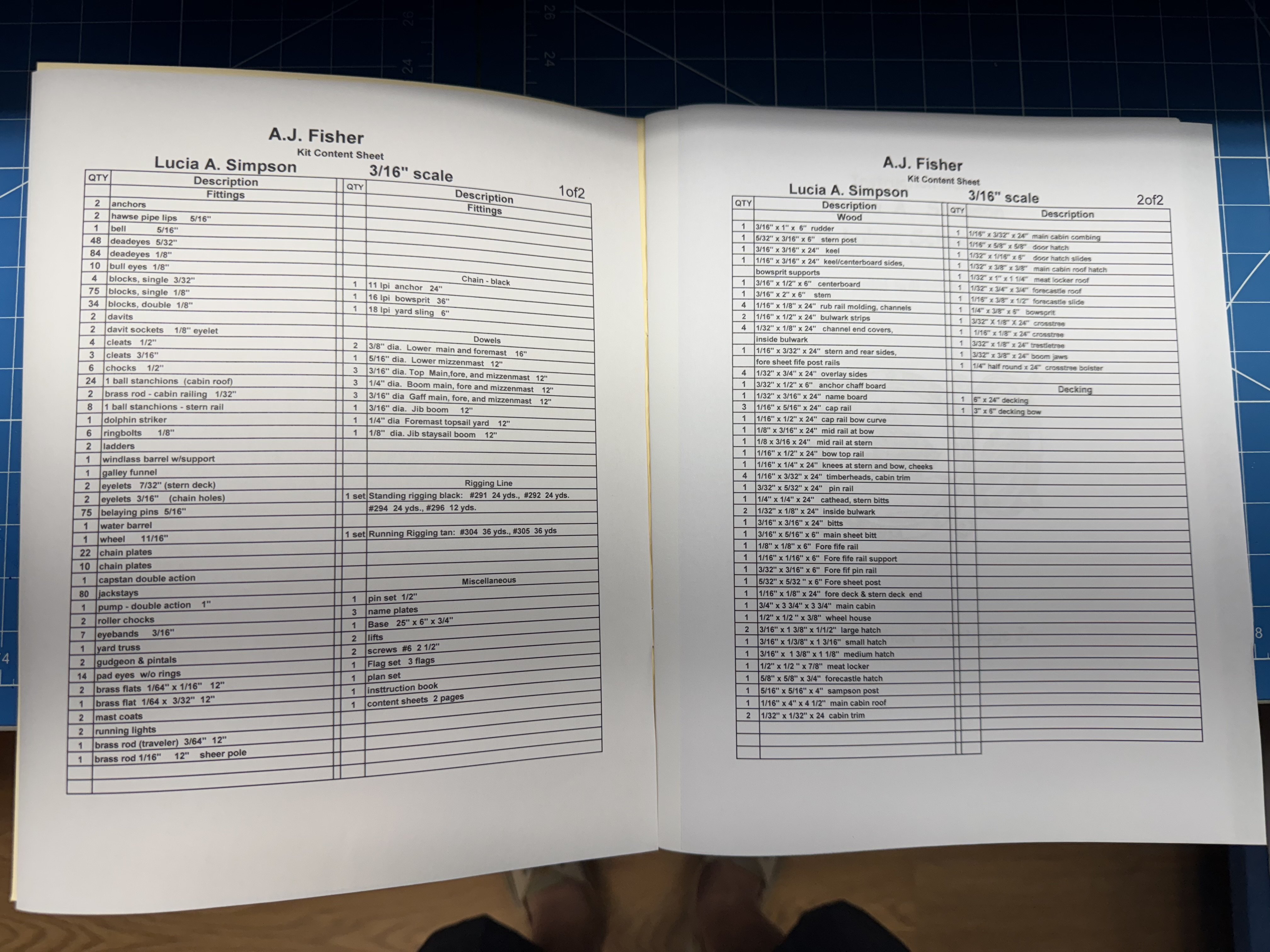
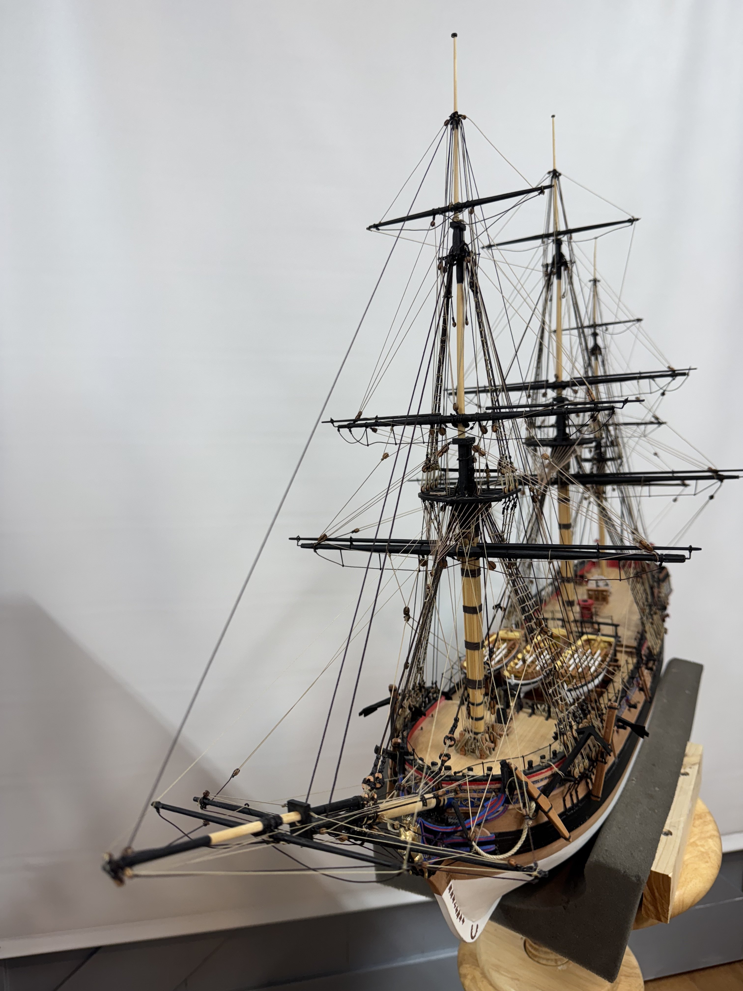
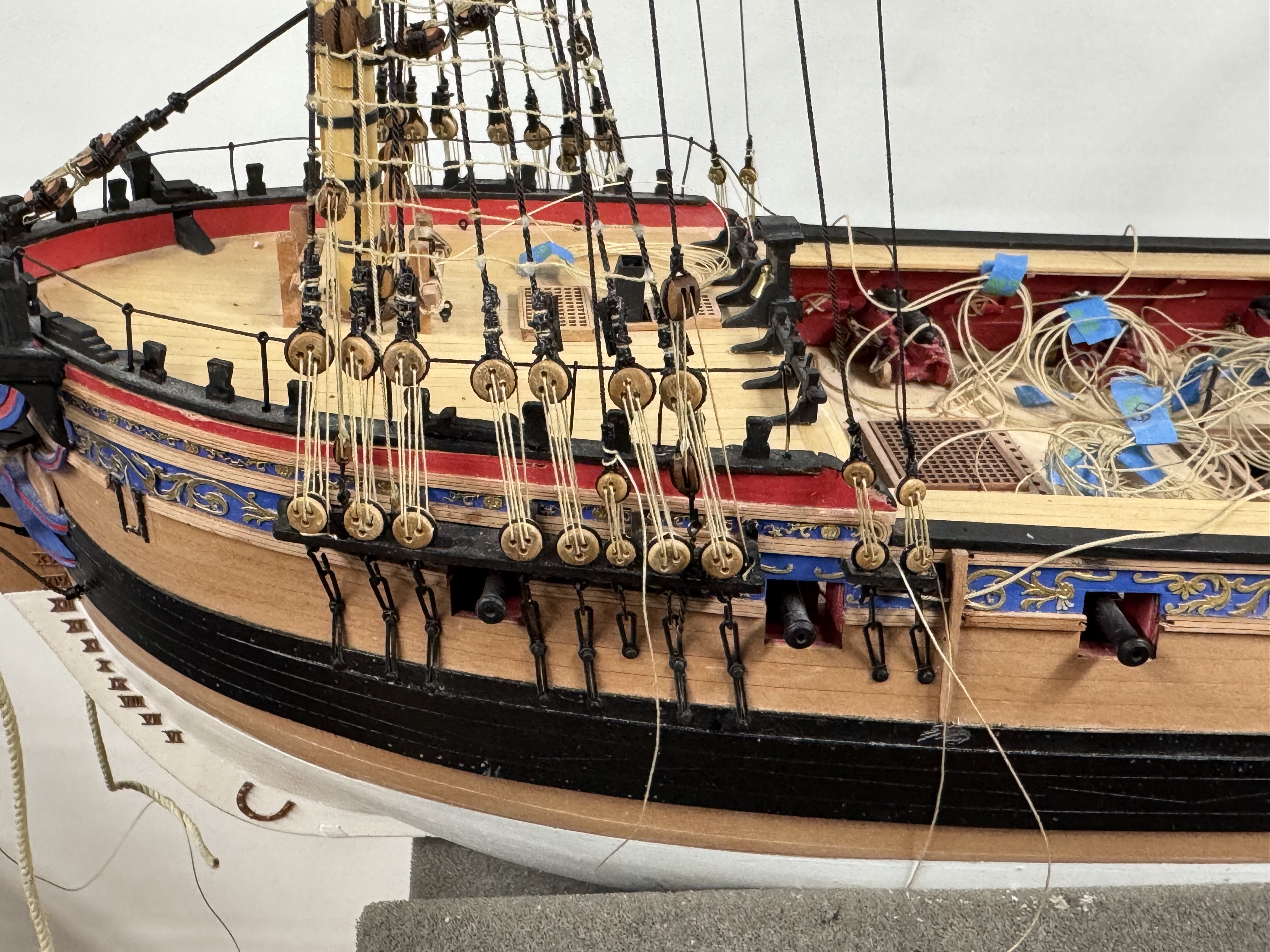
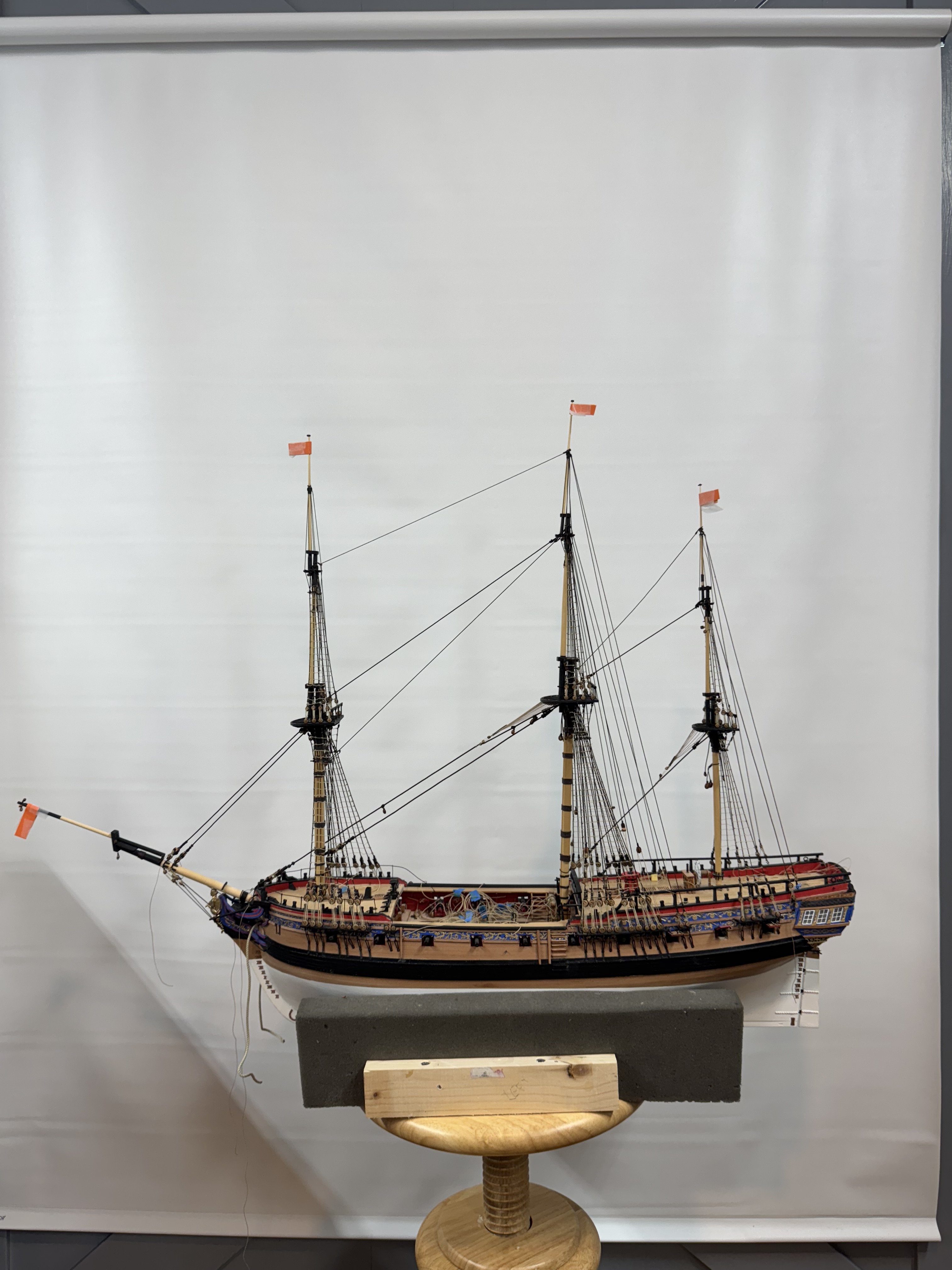
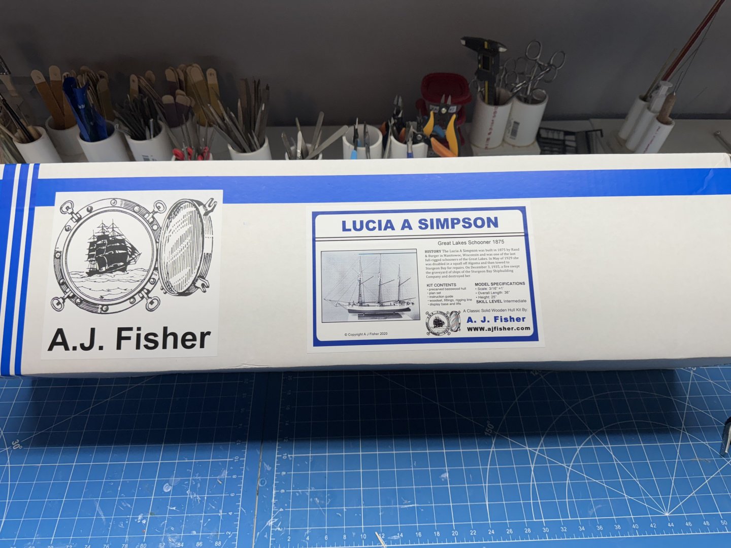
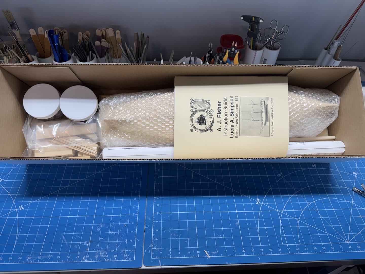
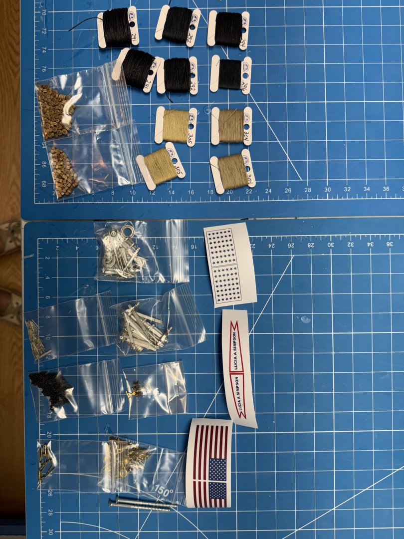
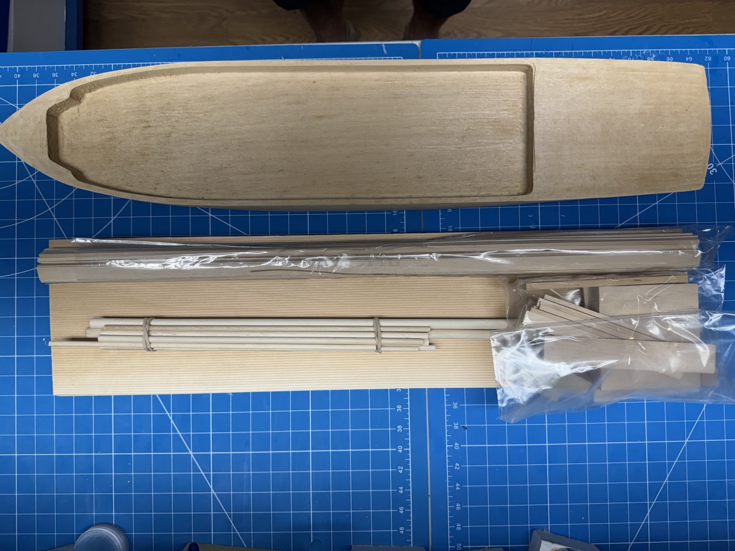
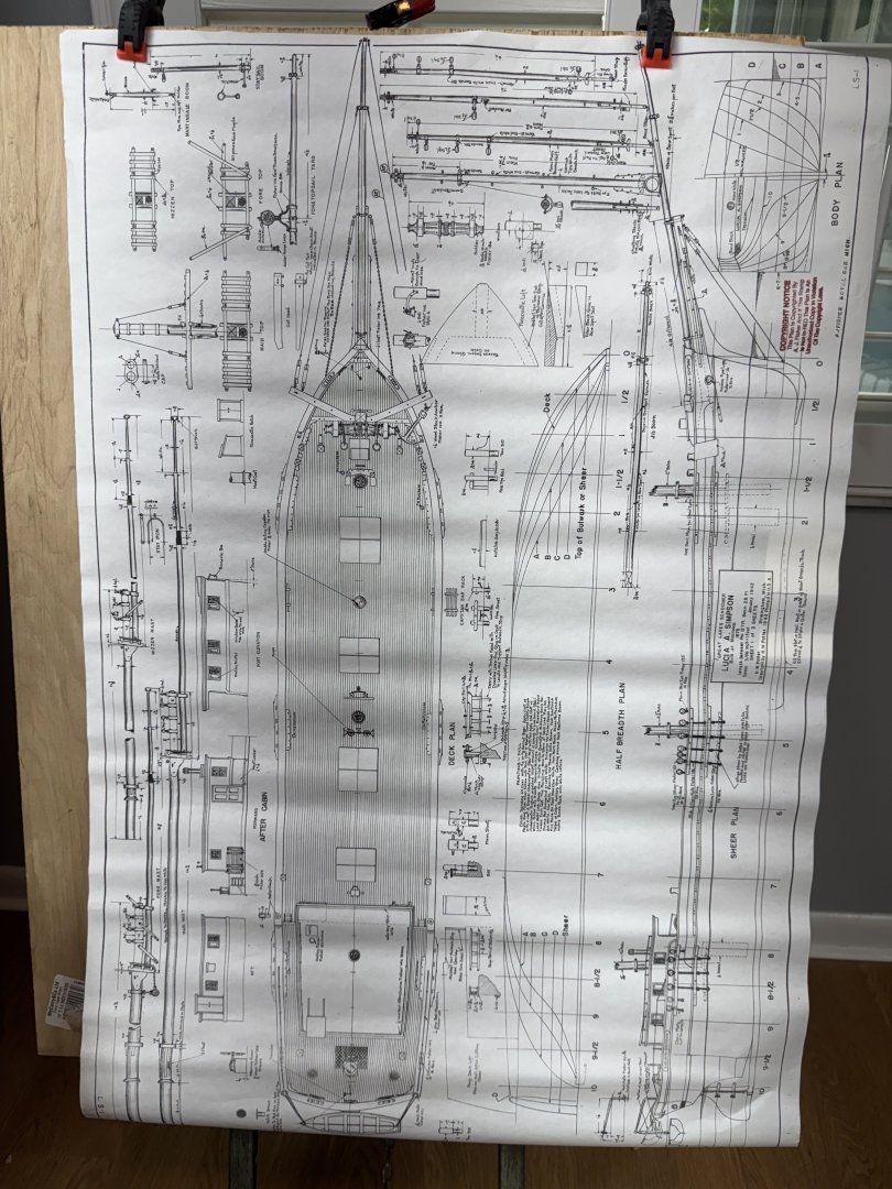
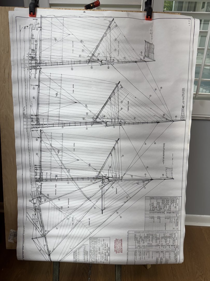
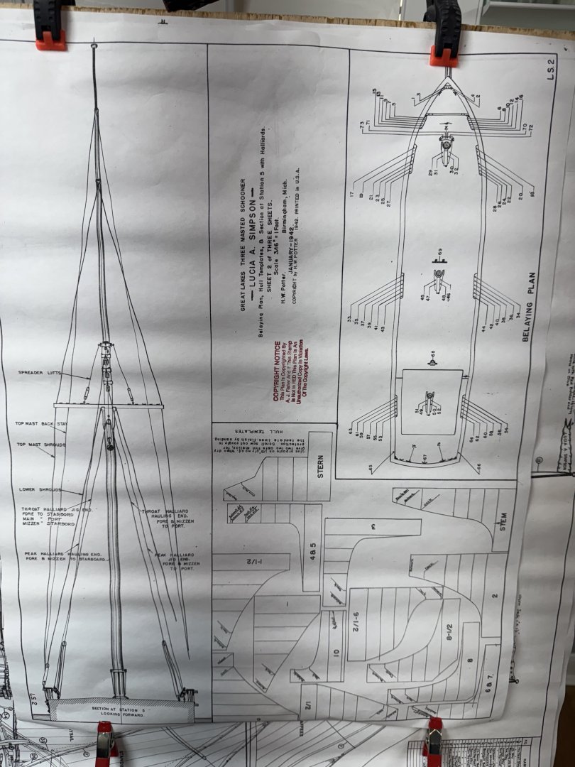
I have searched through the site and find no mention of the Simpson or A. J. Fisher so I suppose this is the first build log for this ship. In case you were wondering the Simpson is a three masted Great Lakes schooner. She was one of over 1700 such vessels that plied the Great Lakes carrying general cargo in the last half of the 19th century. My interest in Great Lakes schooners (aside from spending most of the first 20 years living very near Lake Michigan) was kindled by seeing the Denis Sullivan a replica of a Great Lakes schooner that I saw at the Tall Ships Erie in 2019. After I returned home from Erie (after a visit to Bluejackets and the Maine Maritime Museum at Bath) I started looking for a way to model the Denis Sullivan. Even though the Sullivan was built in the 1990s I could find no real info that would permit building a replica. I settled for the Bluejackets Fannie Gorham, a 3-masted, centerboard schooner. I "stumbled on to" the Simpson after seeing an add in the NRG for A.J. Fisher solid hull models and found there were actually two models of Great Lakes schooners available from them. I picked the Simpson because it was the larger scale (1/64 vs 1/96) and the larger vessel with three masts (the other was a two-master). I ordered the kit by mailing an order form on 3/21 and received the kit today (3/28). Being a solid hull model the kit contents are dominated by the solid hull. The two circular items are plastic "jars" with all of the "fittings, rigging thread and paper flags. A parts list is included along with a 52 page instruction manual. In addition to the hull there are two pieces of engraved decking, a selection of dowels for the masts/booms/gaffs, a display stand (which is warped) and two packages of "strip wood". There also three sheets of plans - one for rigging. The plans were rolled up in the box so I will have to "hang them out to dry" to try and get them more or less flat. One sheet with more details on the hull, spars and fittings. And finally one with a belaying plan, details of mast rigging and hull templates. So now that it is here I better start reading the instruction manual.

- 121 replies
-
- 8
-
-
- Lucia A Simpson
- AJ Fisher
- (and 1 more)
-
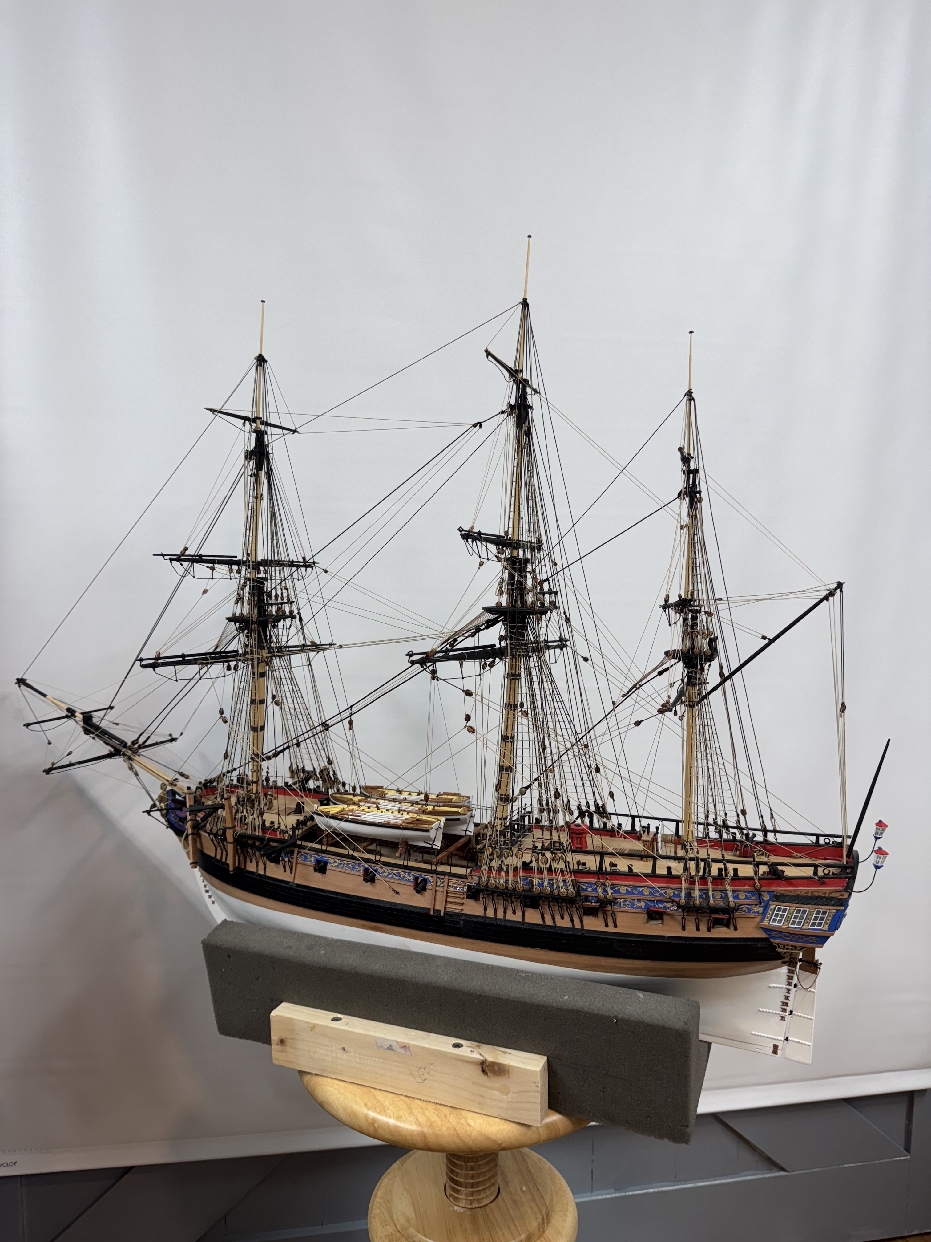
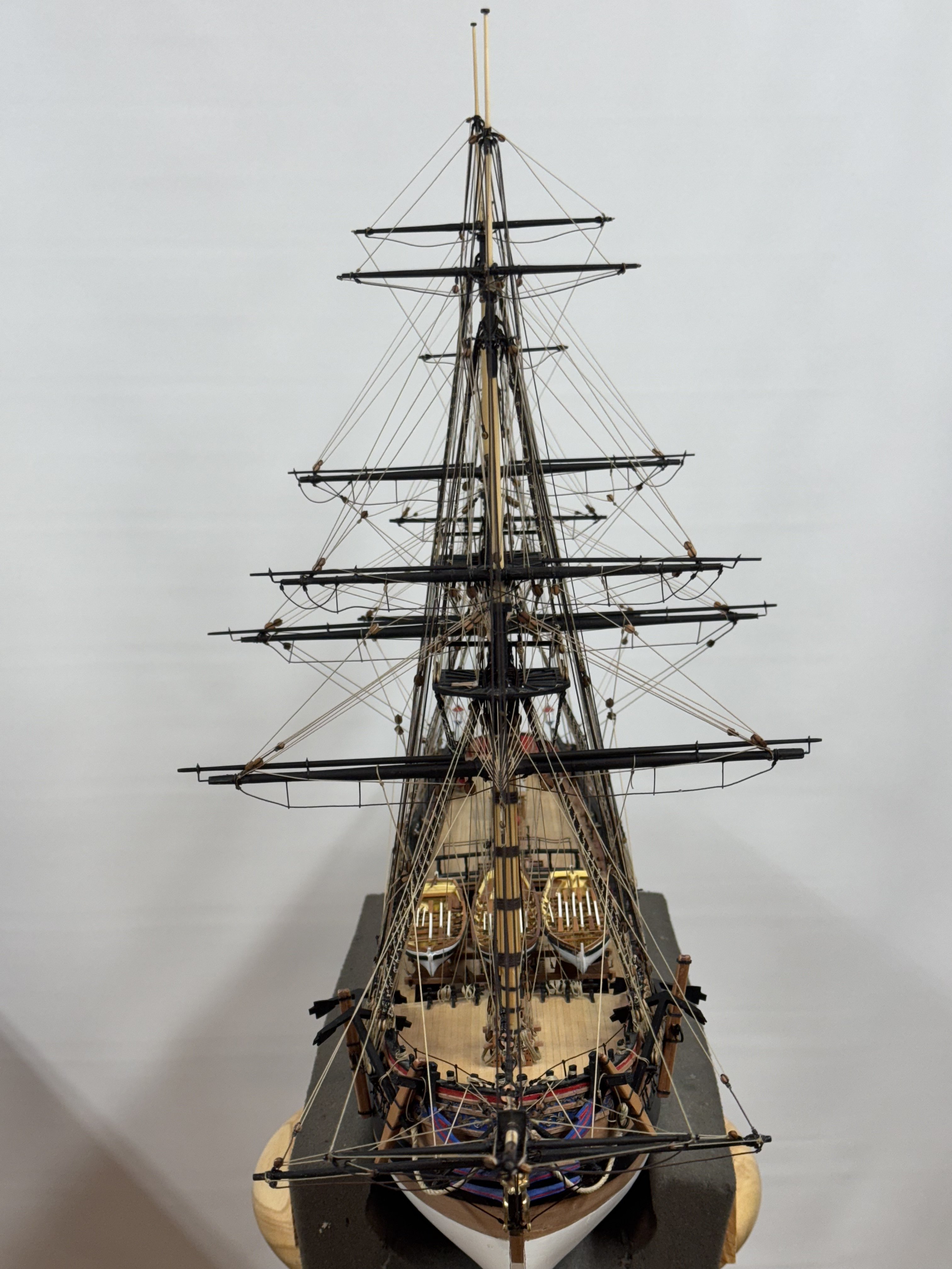
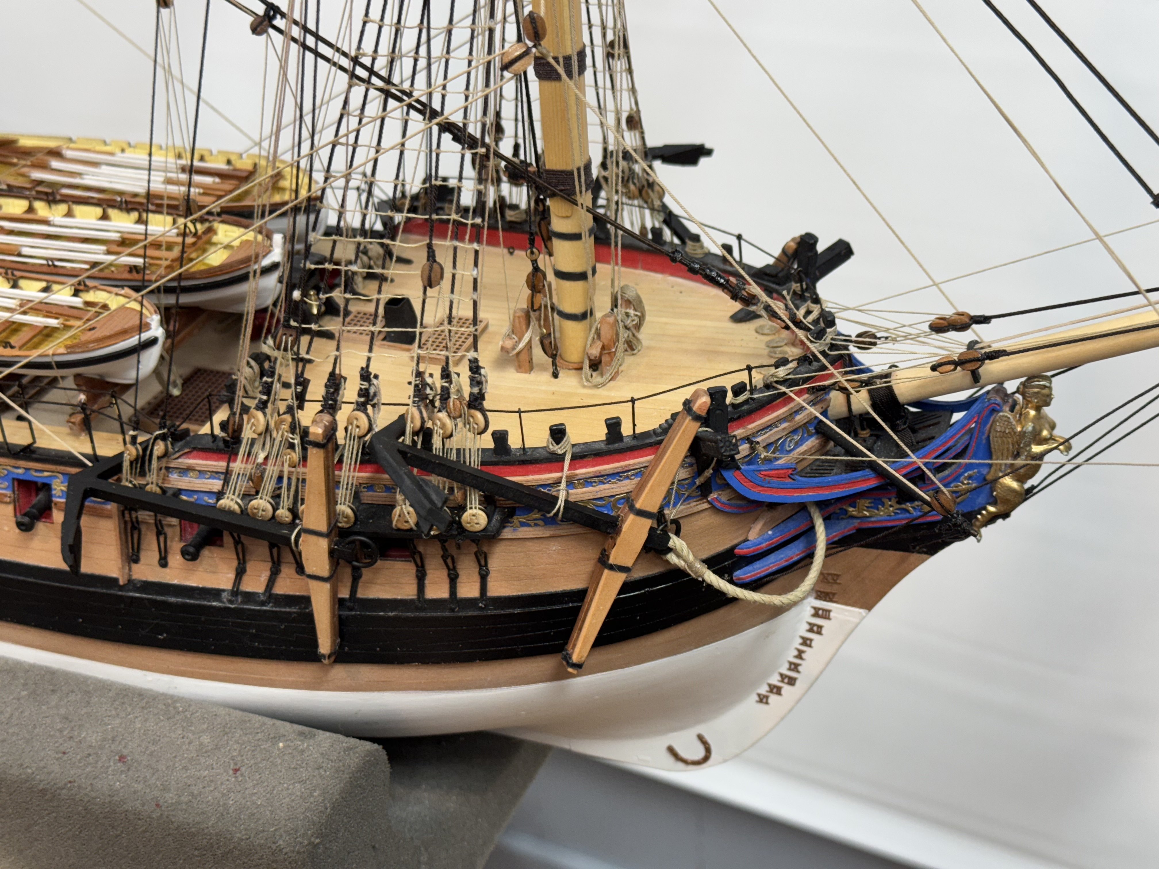
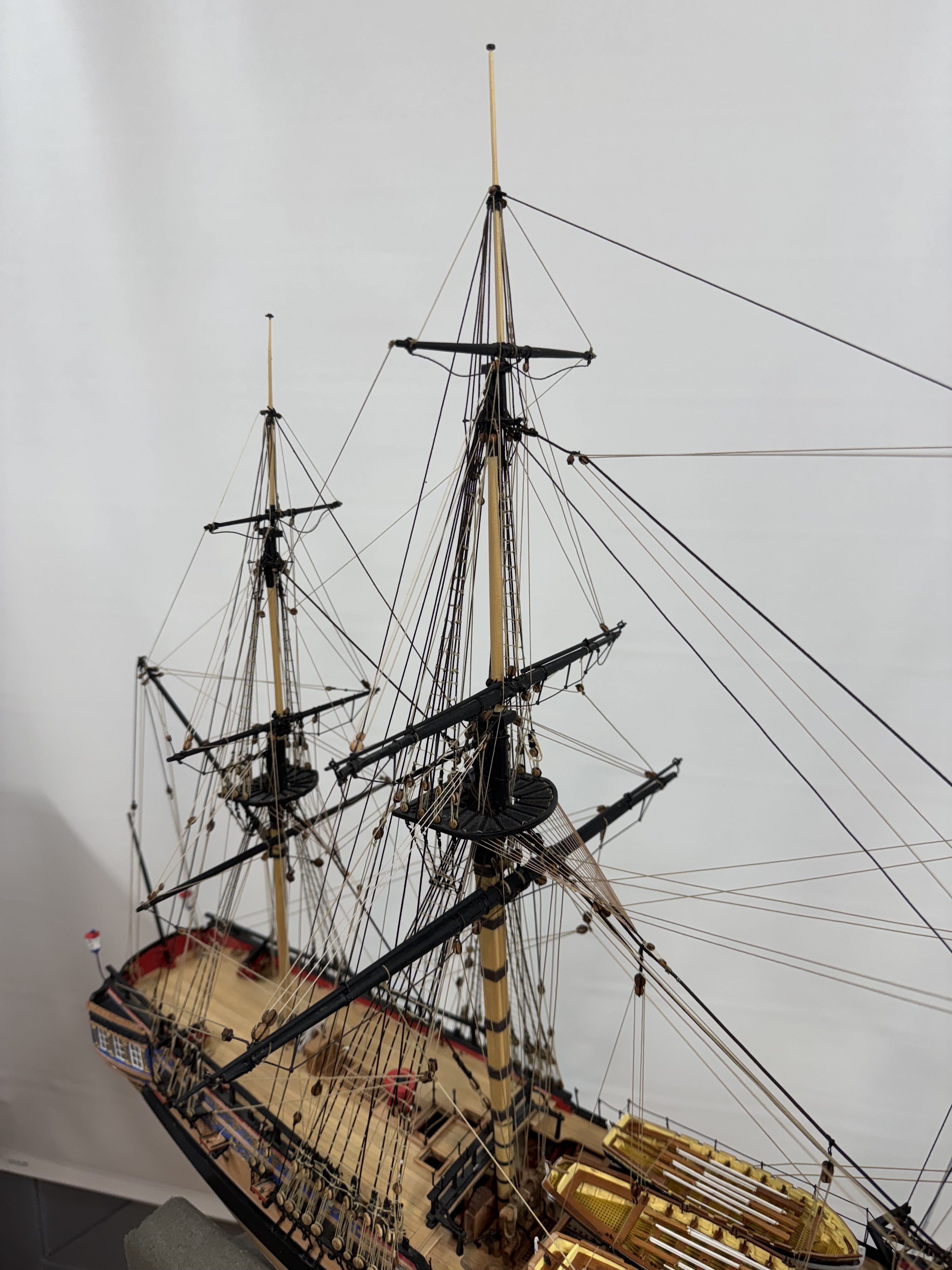
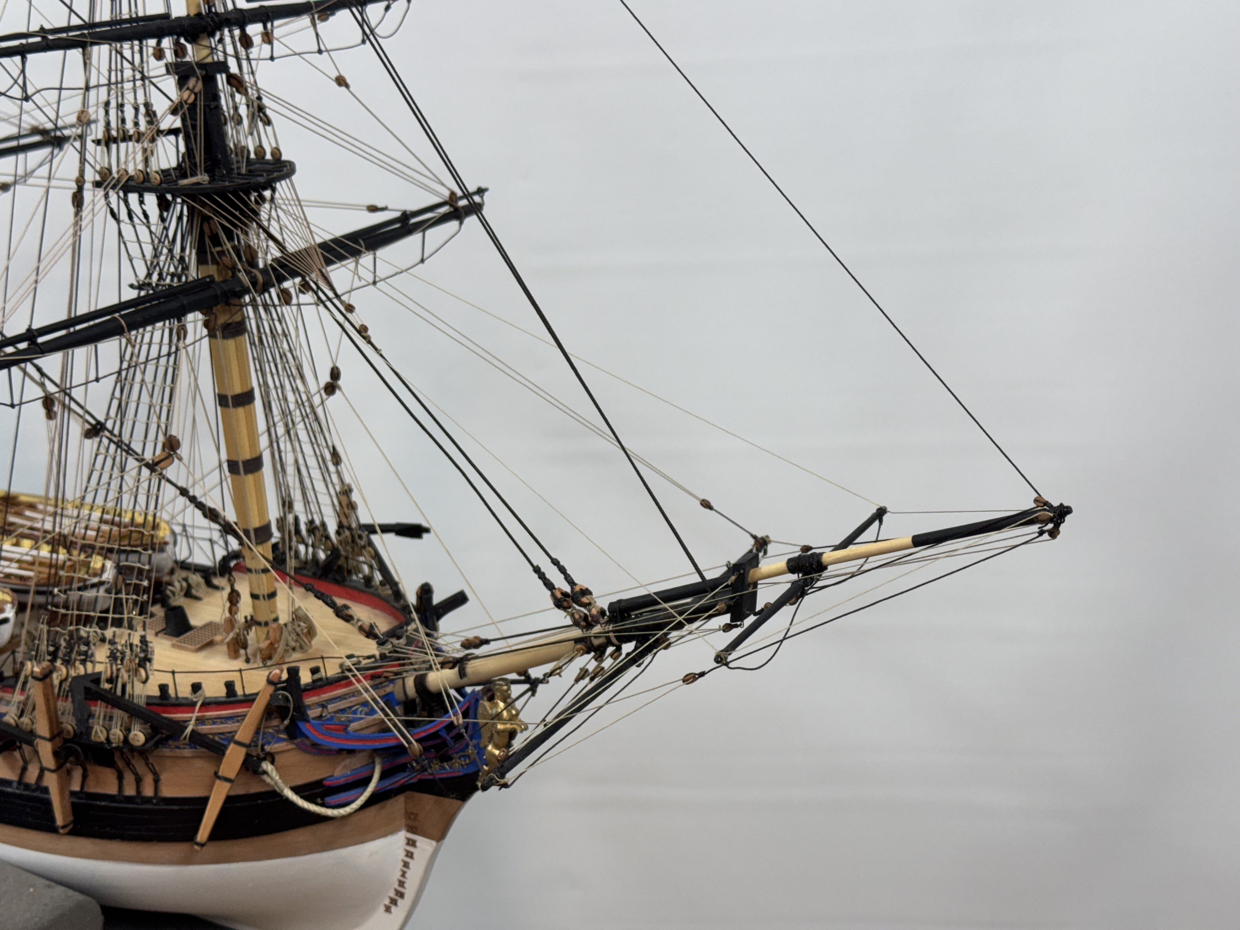
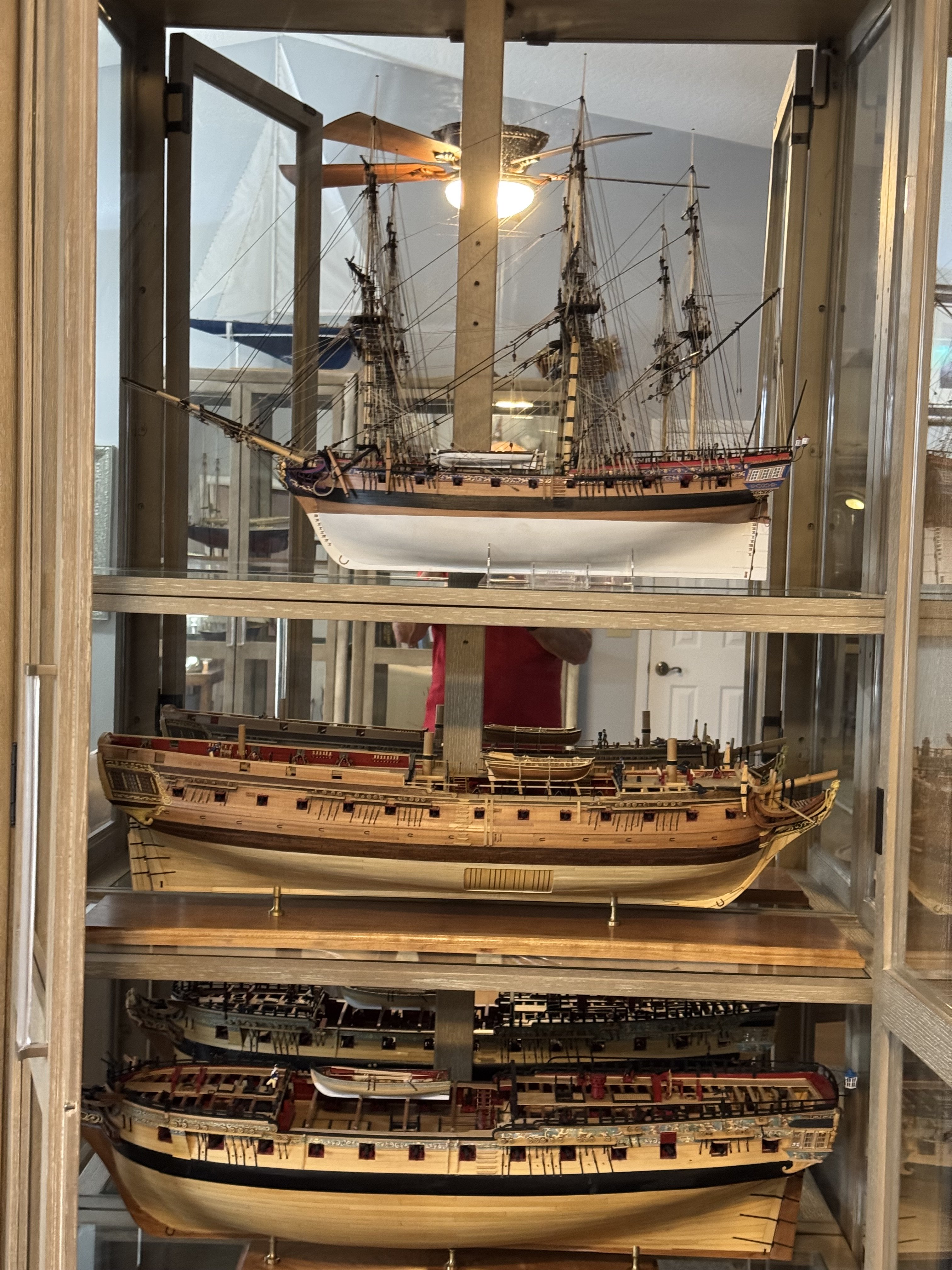
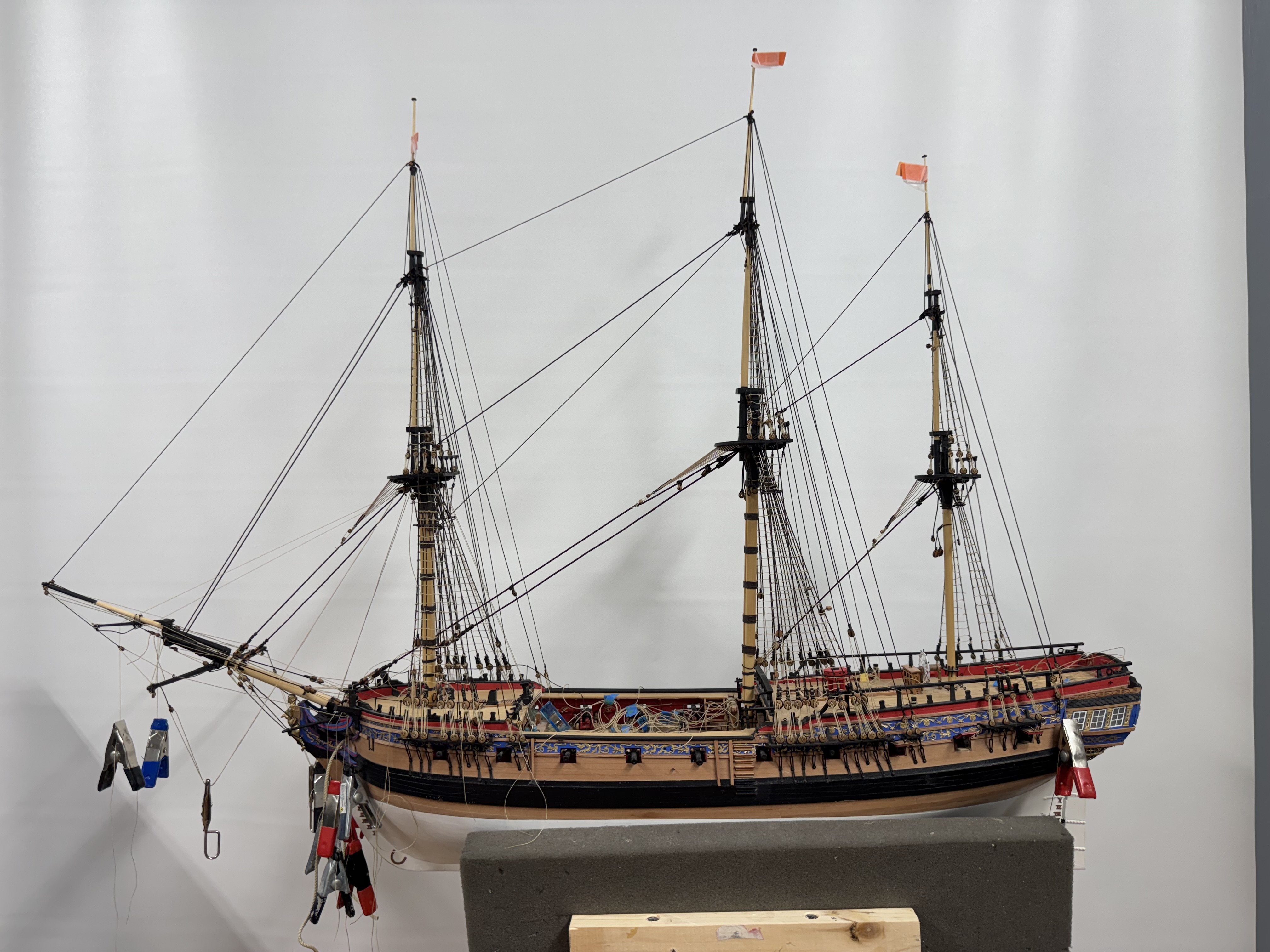
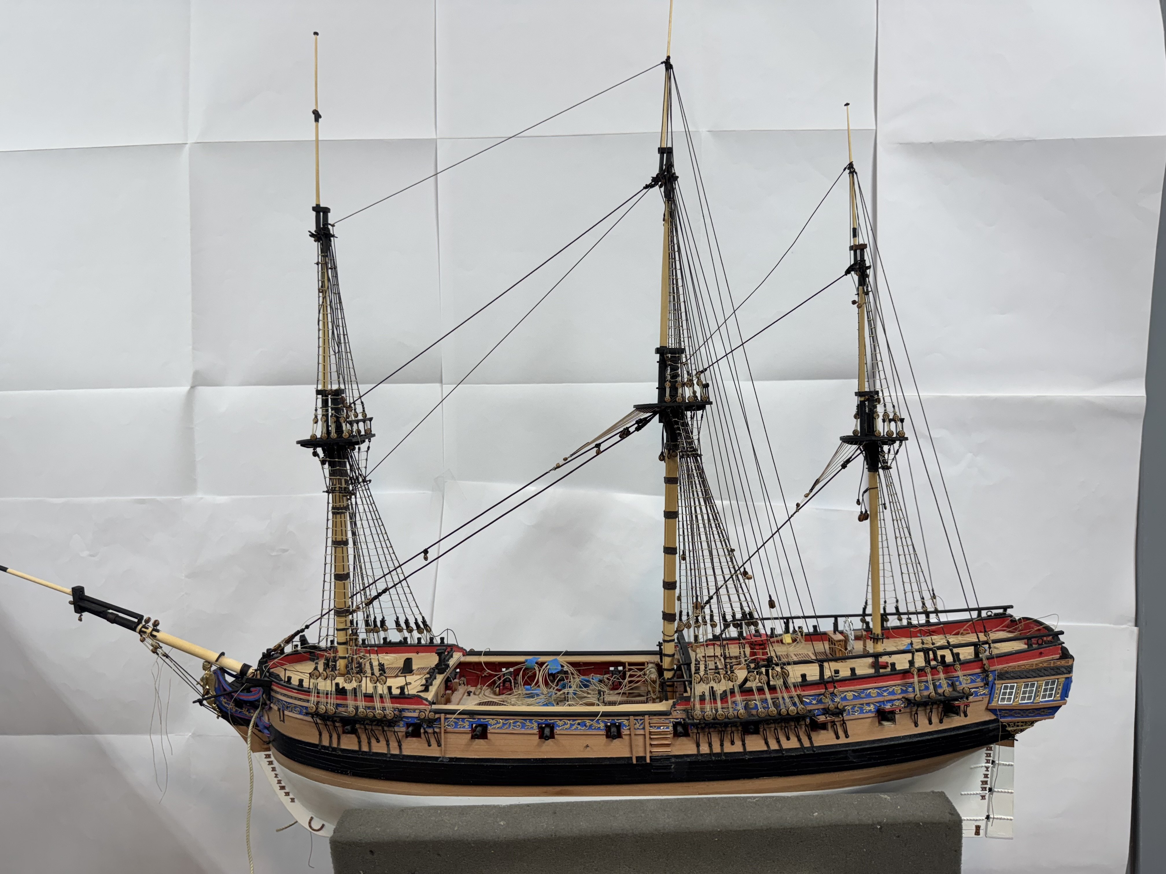
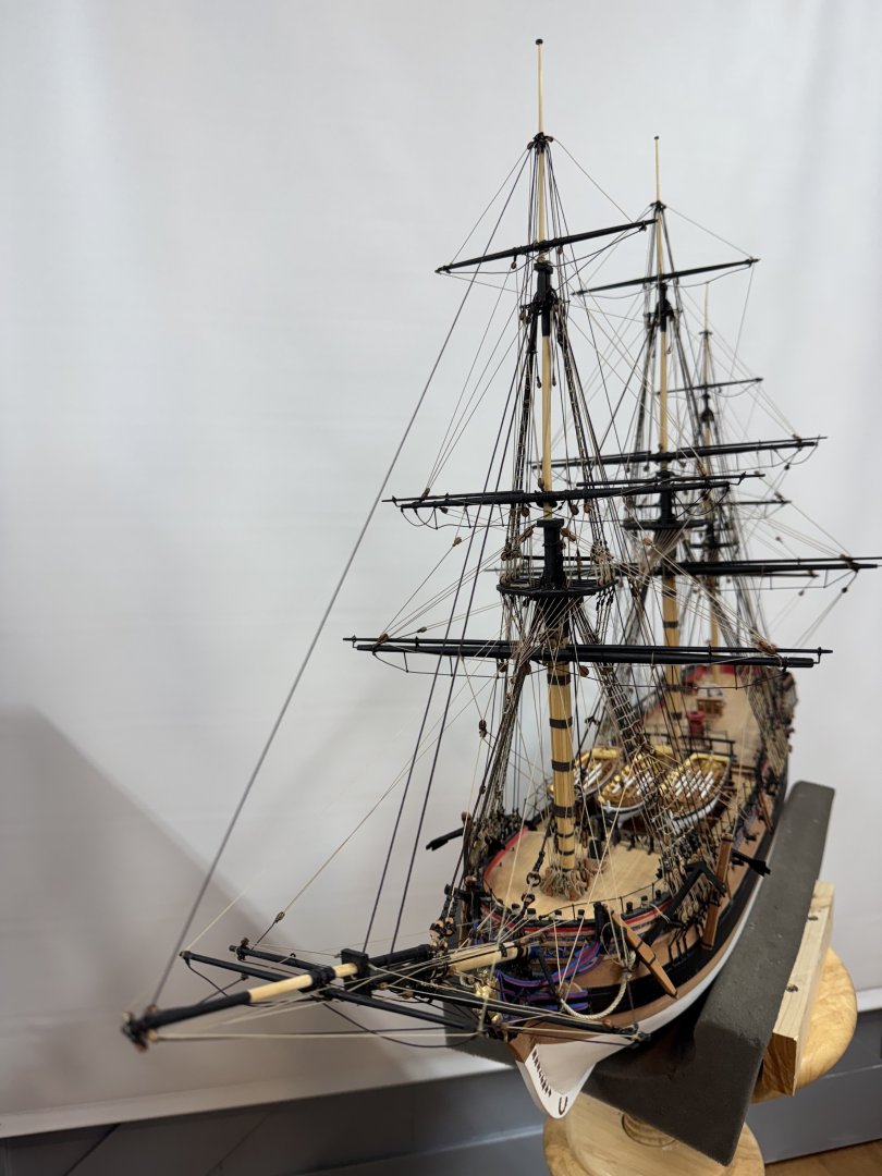
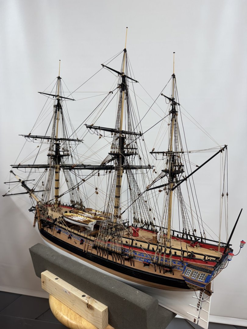
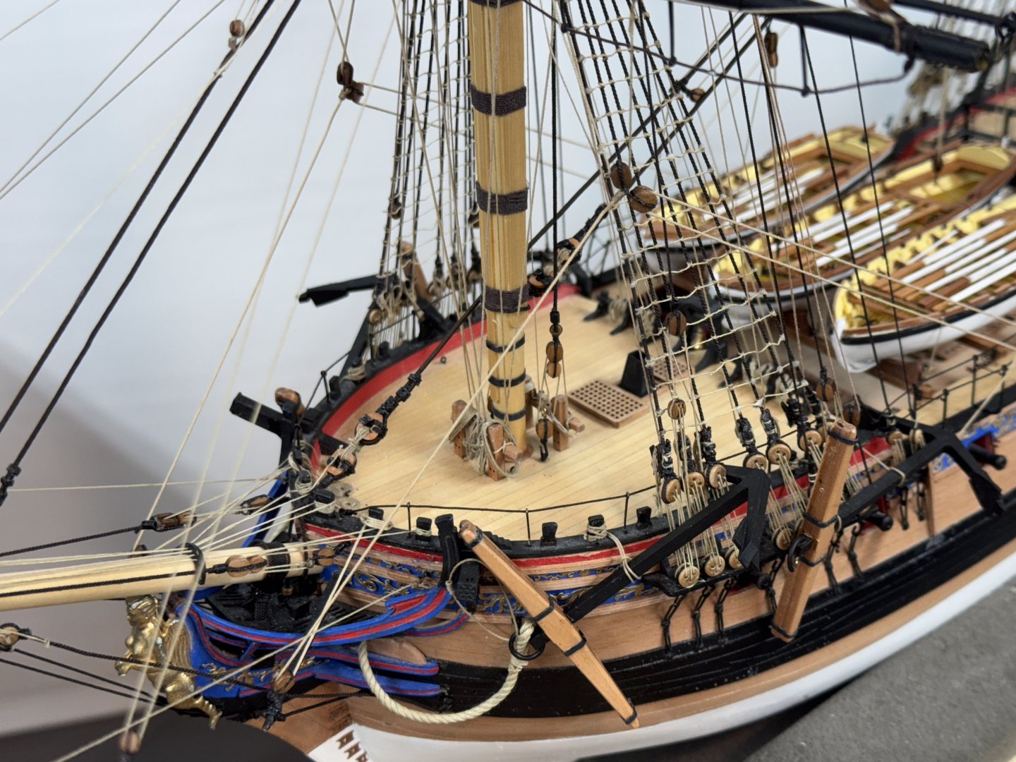
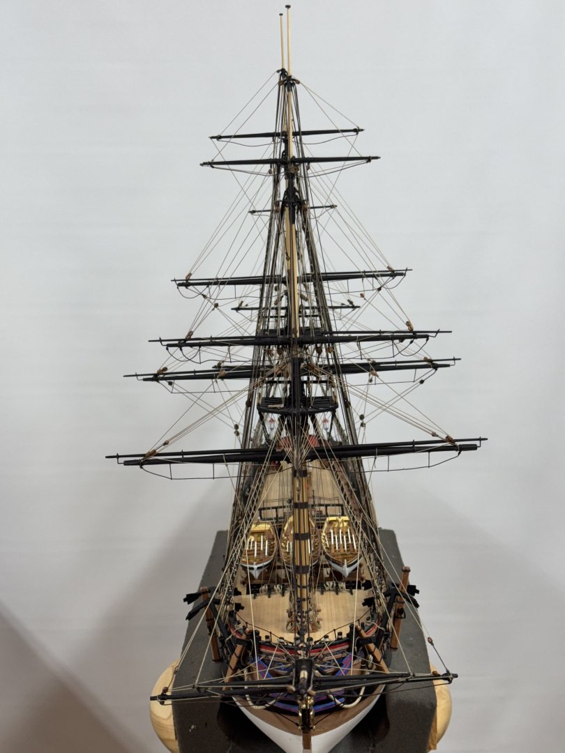
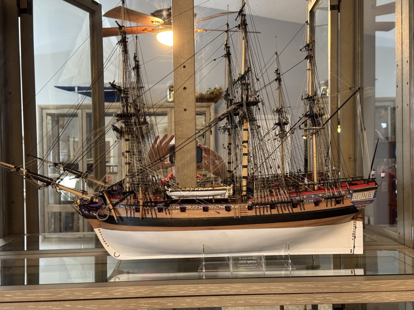
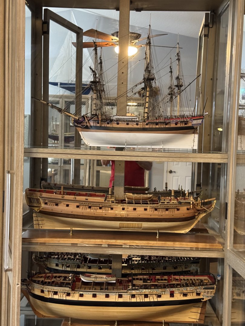
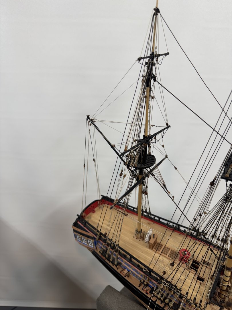
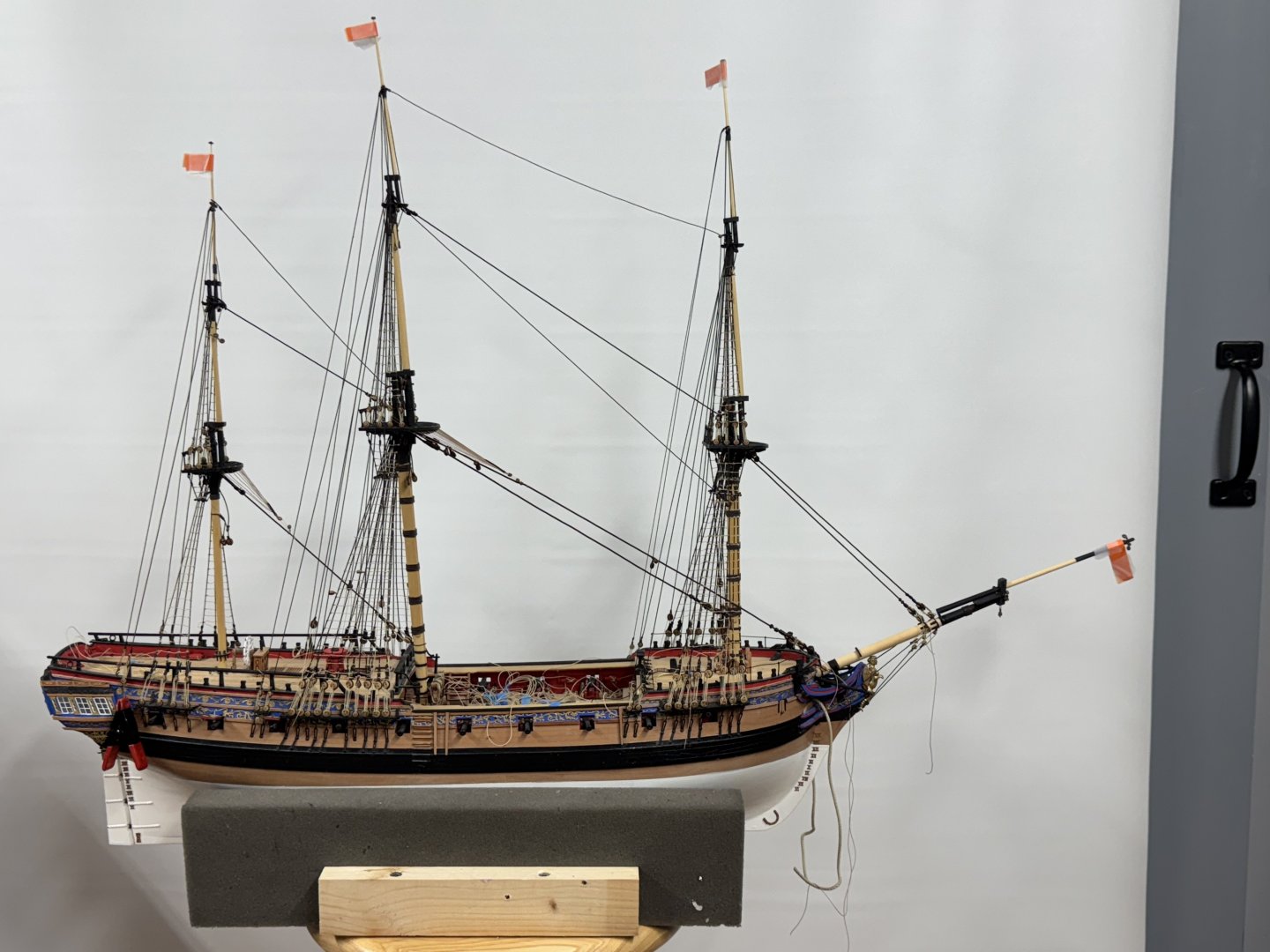
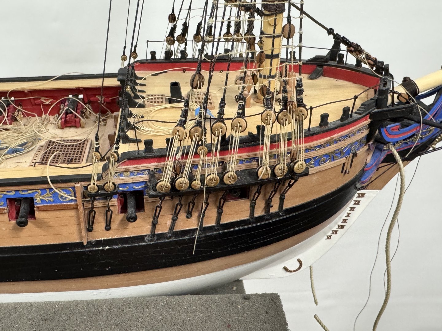
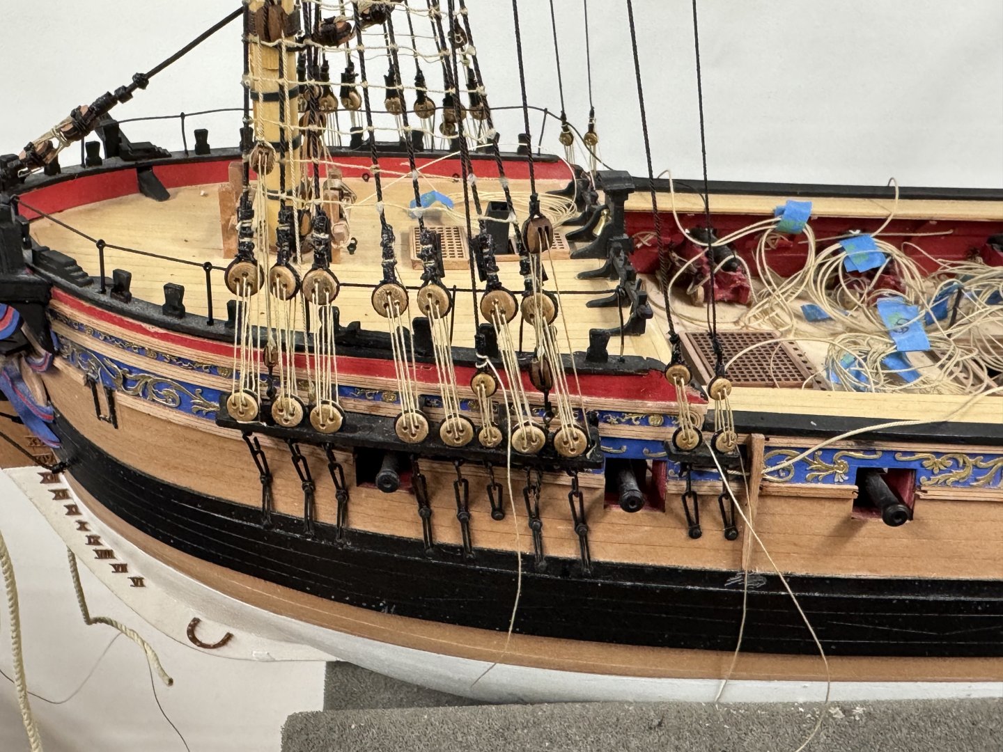
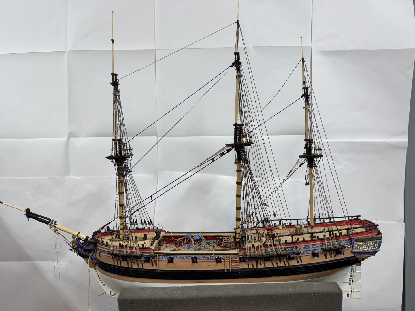
My version of HMS Sphinx is COMPLETED! Here are what she looks like. I would have done some cropping but my experience with this site makes we not waste the effort. And here she is in the display case: Along with Confederacy and Winchelsea


- 422 replies
-
- 19
-
-

-
- Vanguard Models
- Sphinx
- (and 1 more)
-
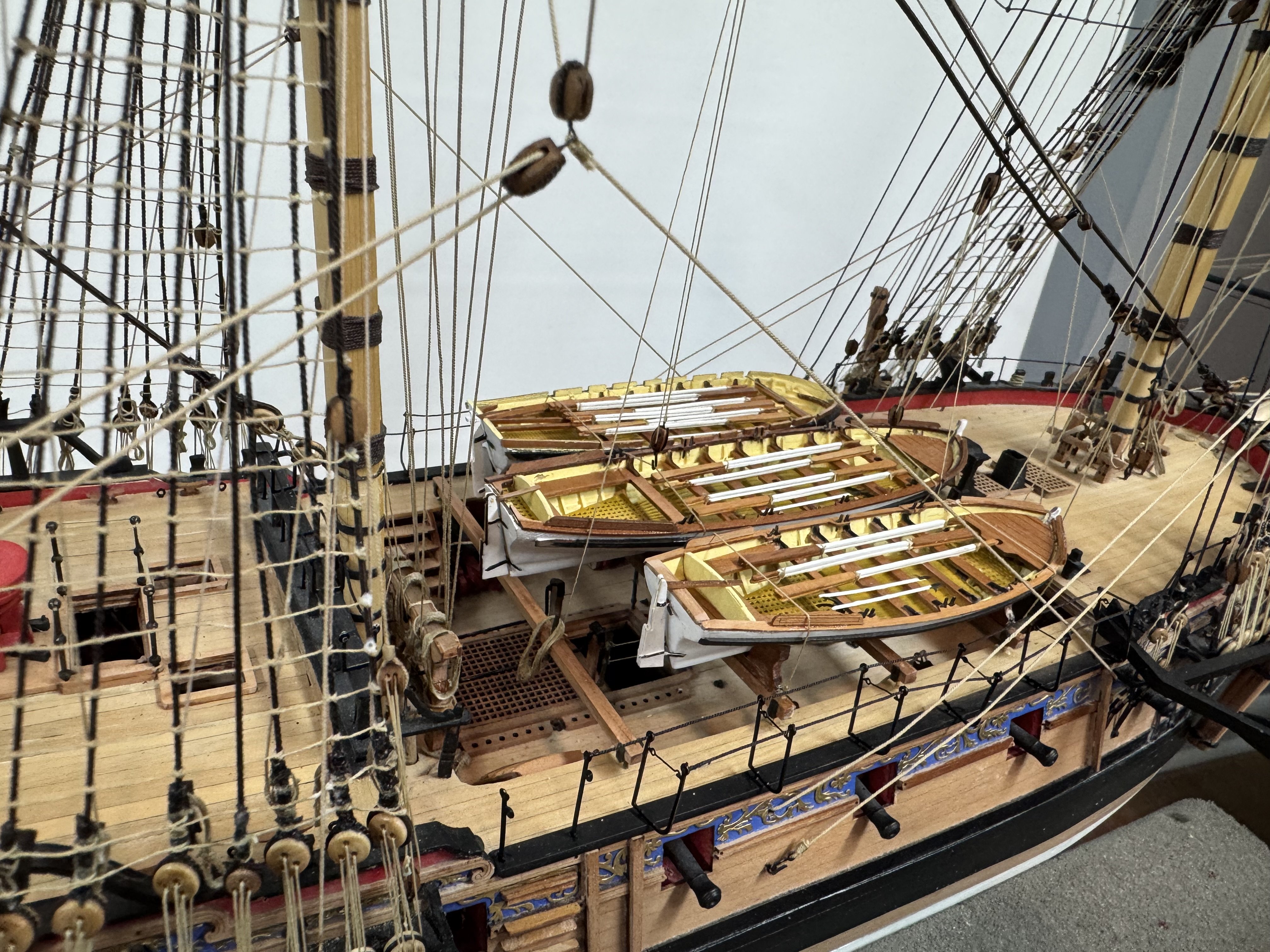
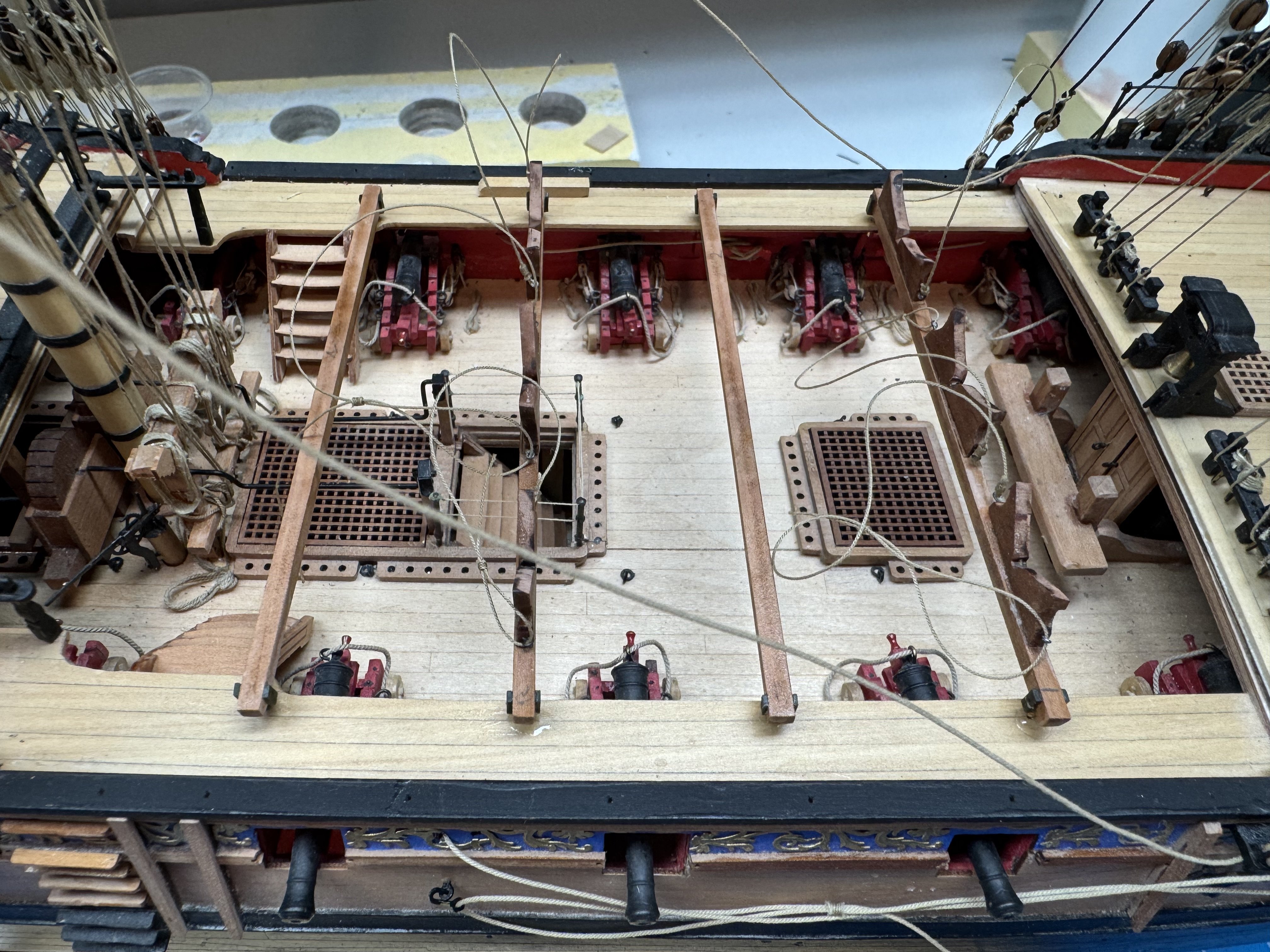
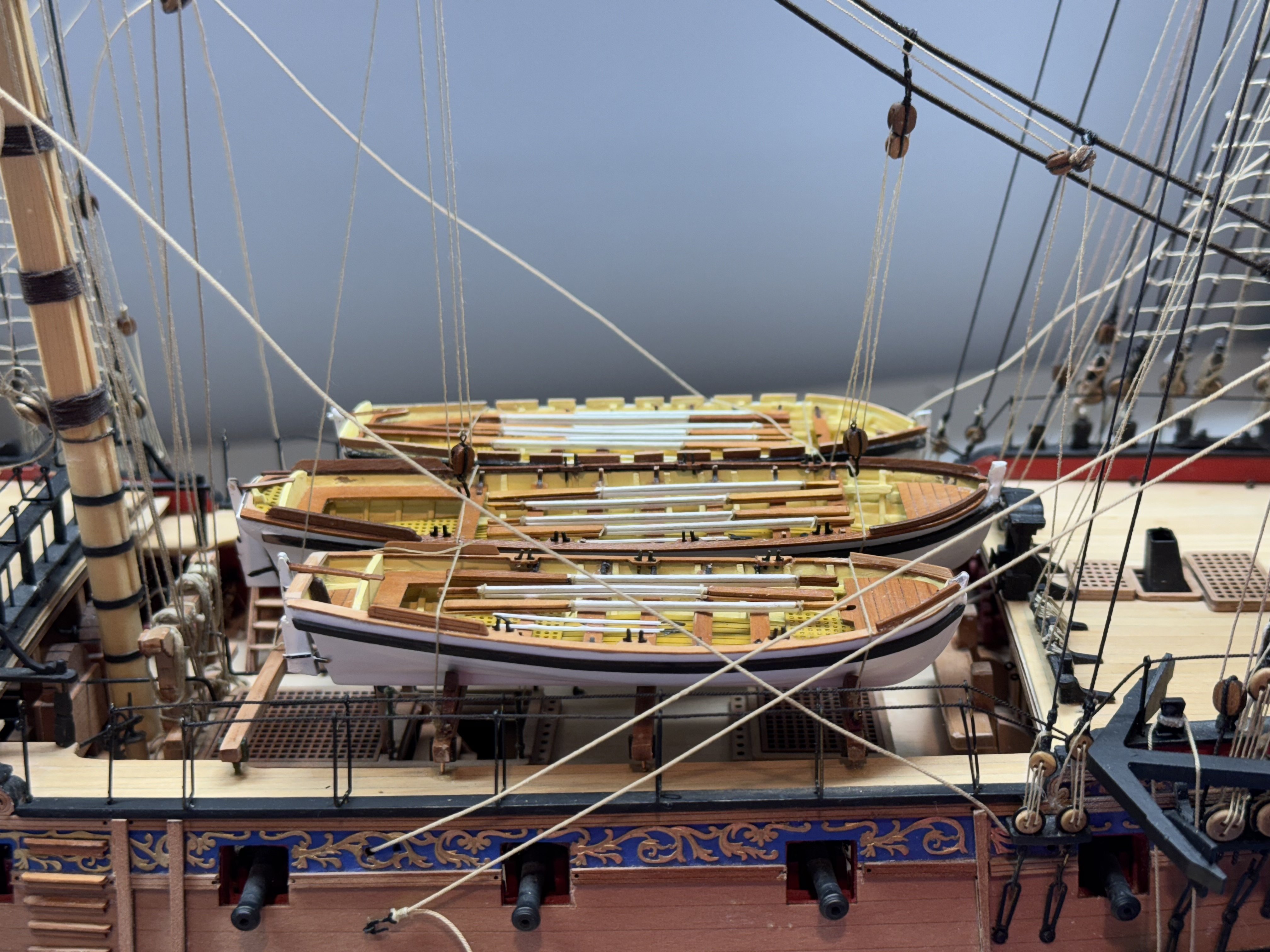
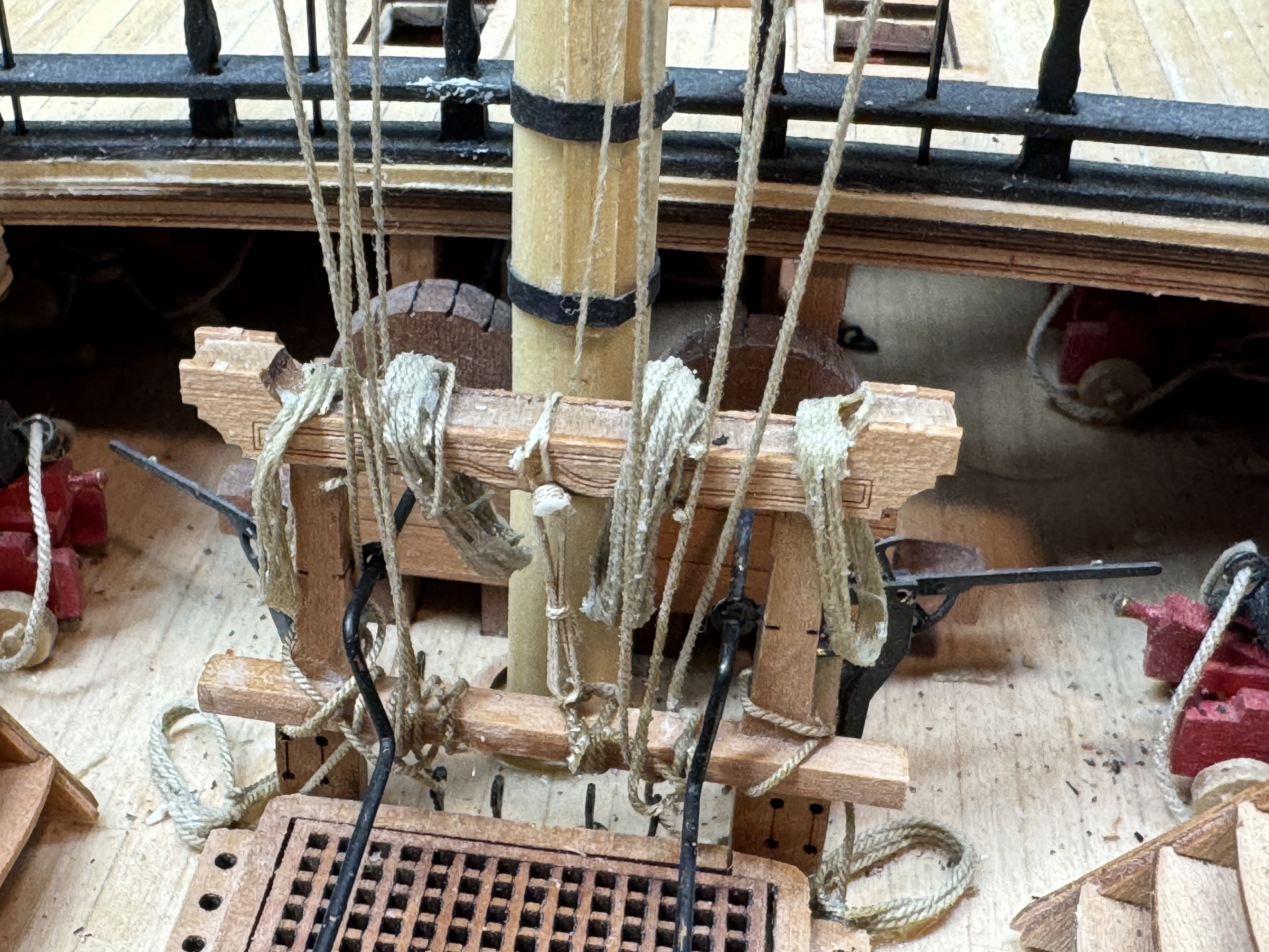
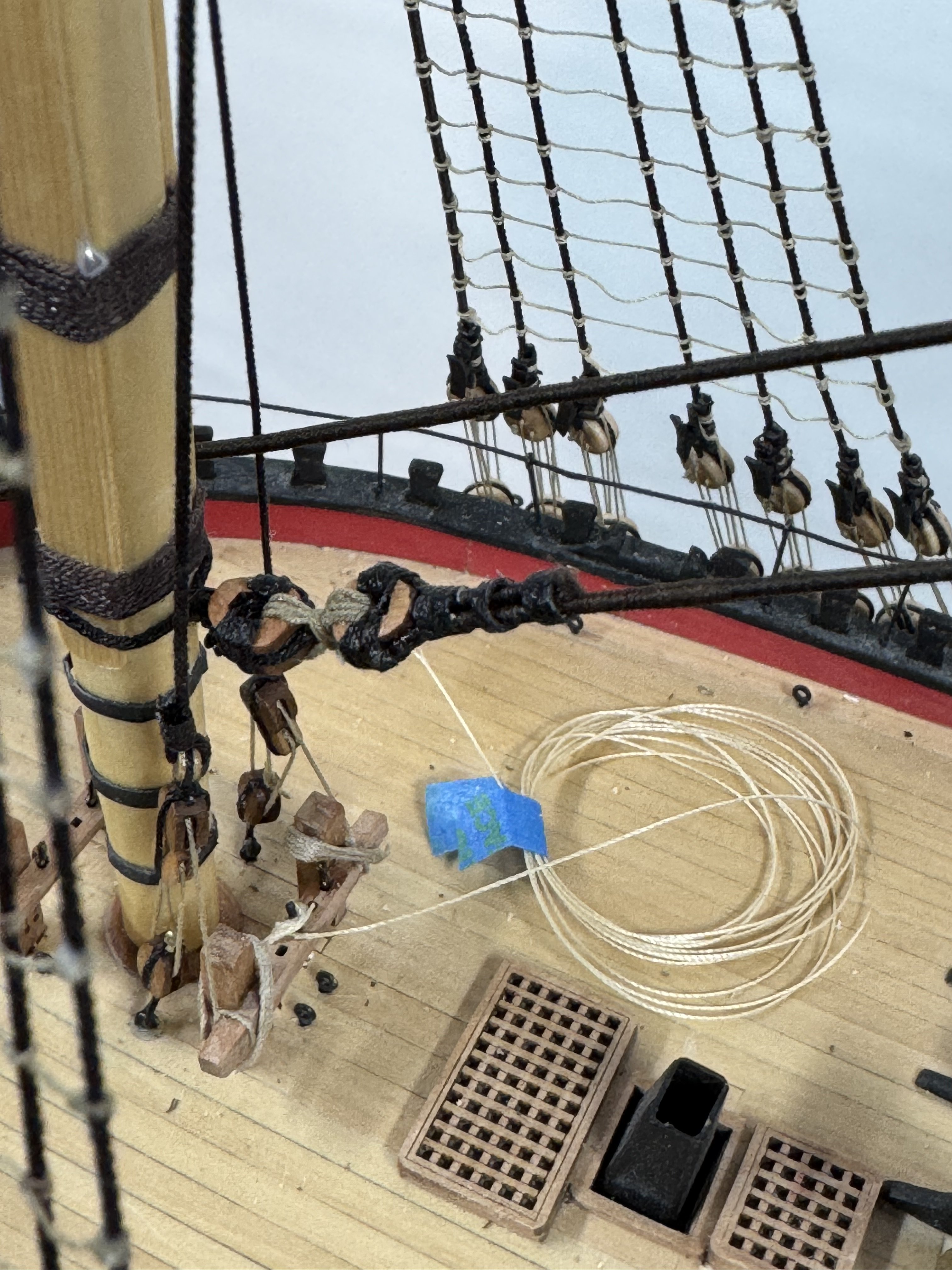
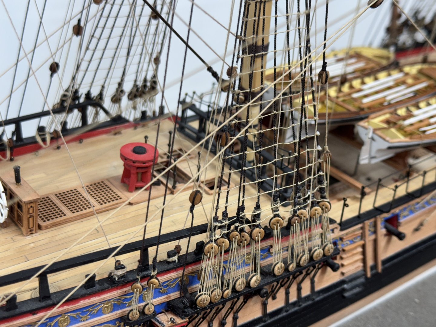
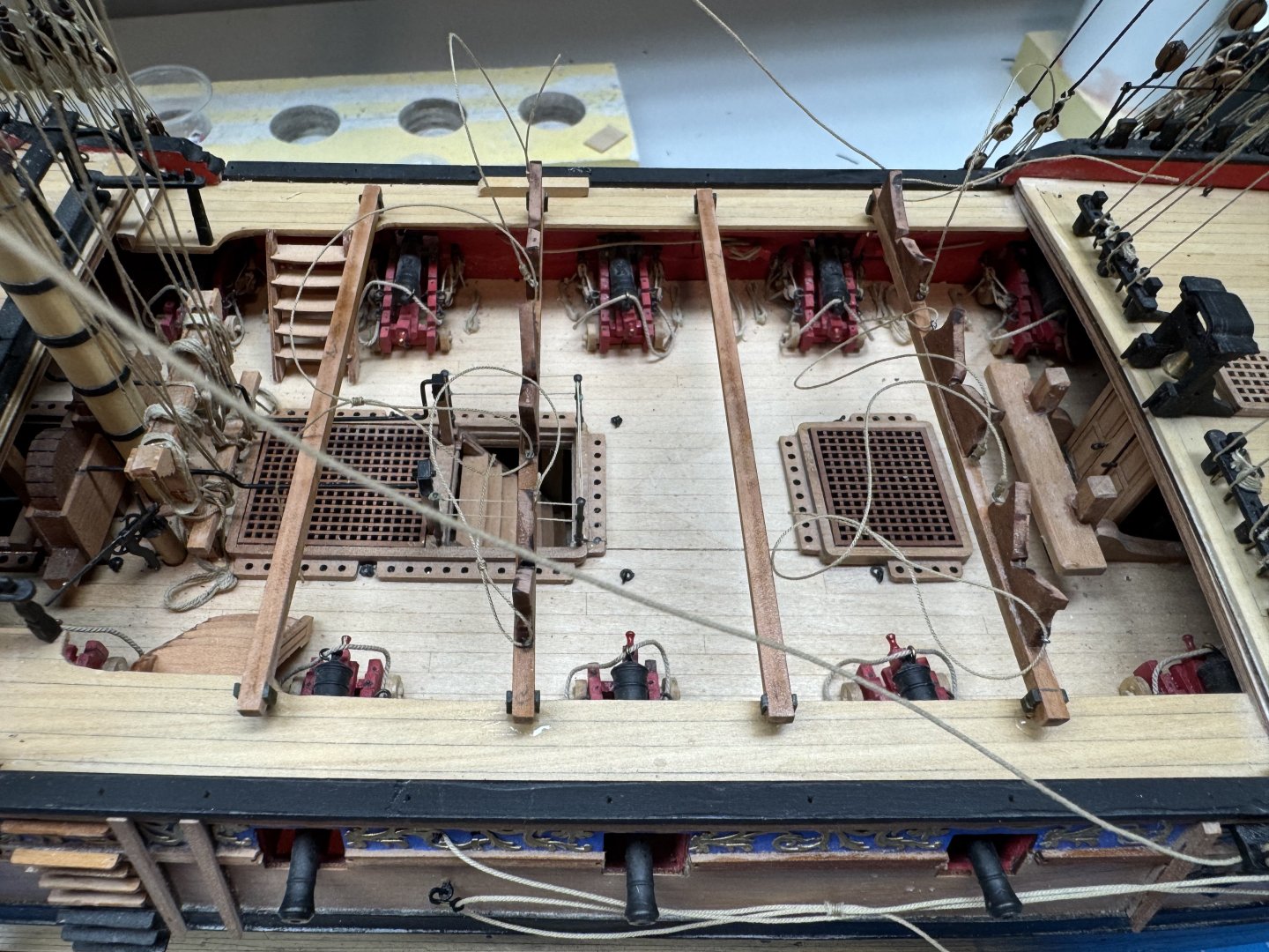
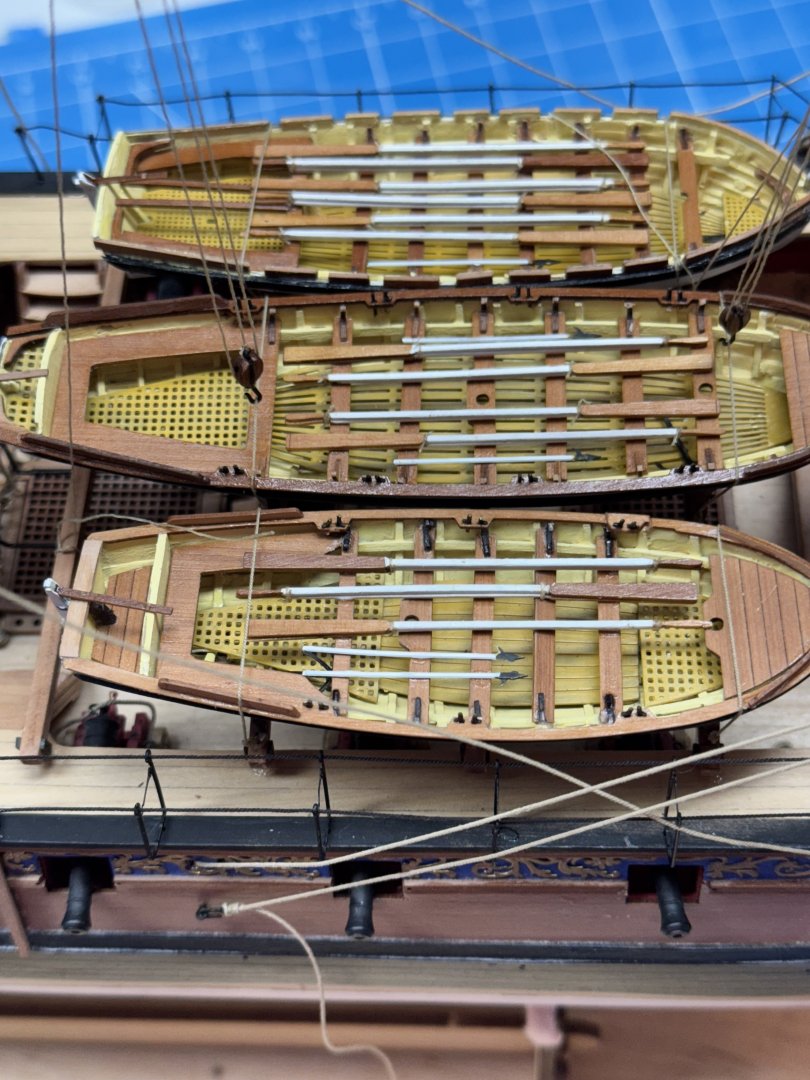
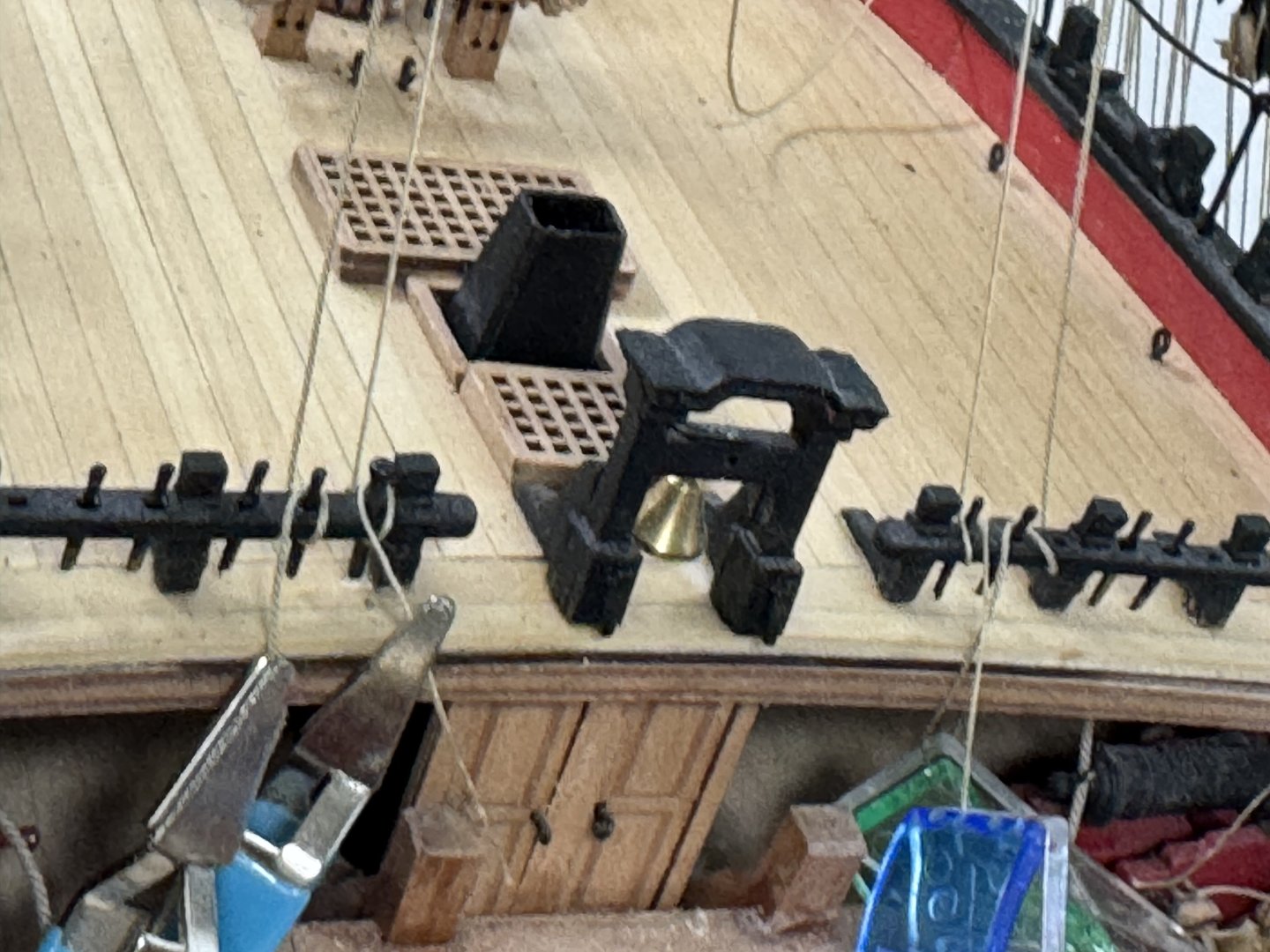
With the line belaying and rope coil placement completed at the bow and waist it is time (finally - I built the ship's boats before I started on the hull) to install the deck beams, chocks and "get the boats aboard". It seemed like a pretty straightforward task - but... The first issue involved the "feet" supplied that stand the deck beams off from the deck. They are made of some kind of plastic which I found to be pretty fragile. I started with the two beams (#2 and 4) which do not have the boat chocks. I managed to get them both in place but subsequent movements caused the little pins that seat in the deck to break off. I had to cut off/sand the remaining foot, drill a hole and CA a .025" phosphor-bronze pin into the hole. Then I used a 3/32" block to keep the beam at the same level as the others while the glue dried. Before it was all over I had to replace the plastic pins in five locations. Then the were the boat chocks. Unless you are using the 3D Printed boat hulls it would pay dividends if you checked first if your boat hulls match the chocks (mine didn't especially the keel notch was way too narrow) and then if the boats will fit side by side (mine wouldn't). I had to remove the outer set of chocks and move them further outboard than the engravings on the beams show. Even having done that they are still "cheek to cheek". But in the end I got the boats aboard. And then rigged the main stay and forward hatch tackles to the main and preventer stays. I plan to route the bitter end of these tackles into a convenient boat where the extra line will be stored. It is really hard getting access to anything amidships at this point so while probably not standard RN practice it will have to do. I should have rigged the tackles with only the center boat in place - too late now. Next up the anchors. And I am toying with the notion to add two more cannon at the aft end of the quarterdeck. I am sure these ships carried more than the 20 guns on the gun deck. They probably had two on the forecastle and four on the qdeck but I only have two identical cannon (and am in no mood to build more) and getting anything on the forecastle at this point would be"really hard".

- 422 replies
-
- 8
-
-
- Vanguard Models
- Sphinx
- (and 1 more)
-
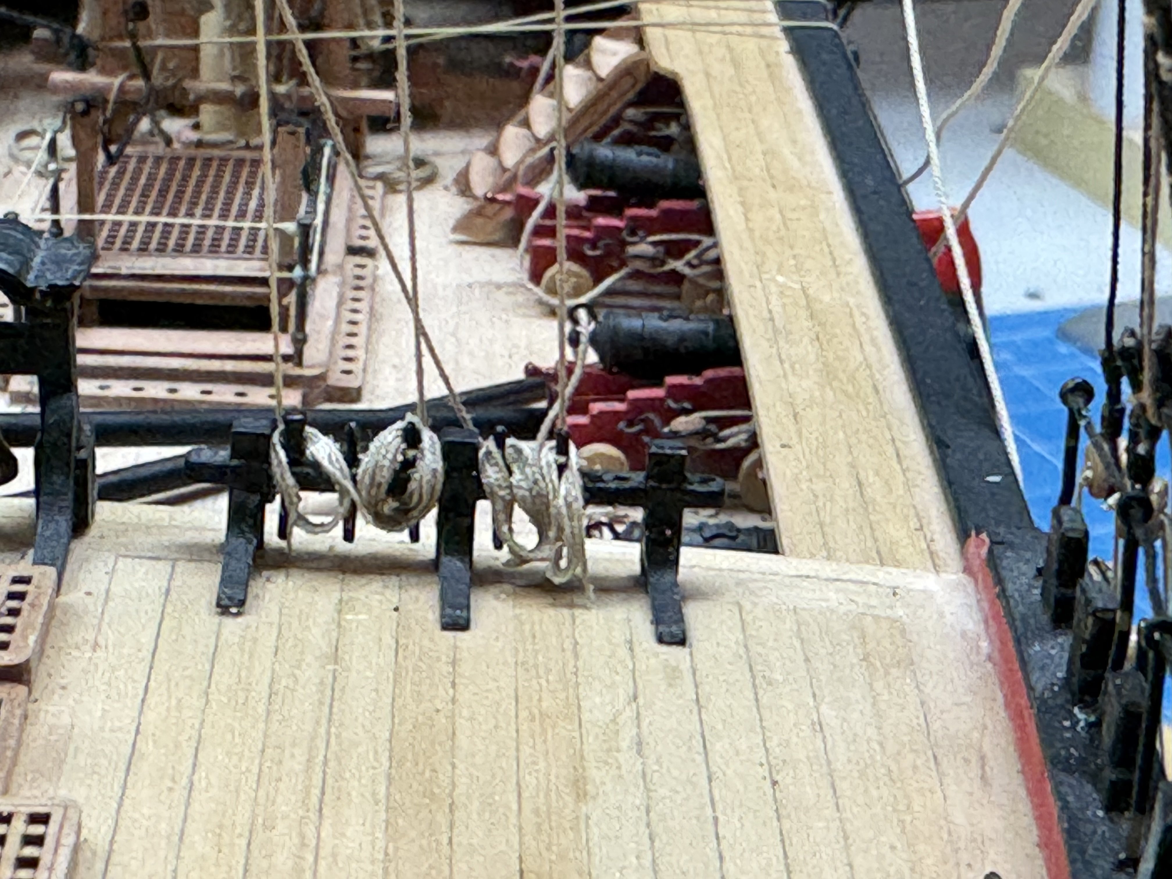
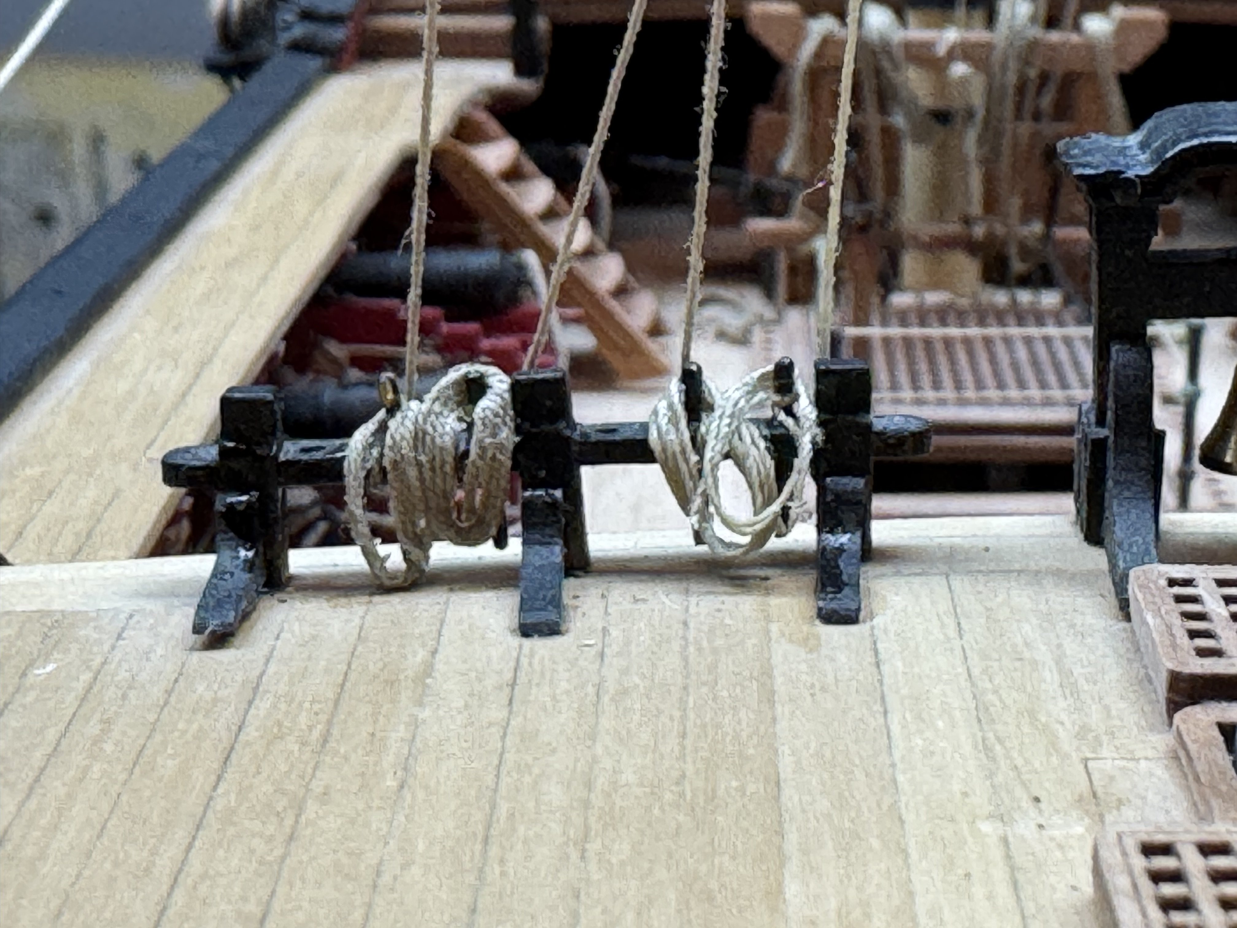
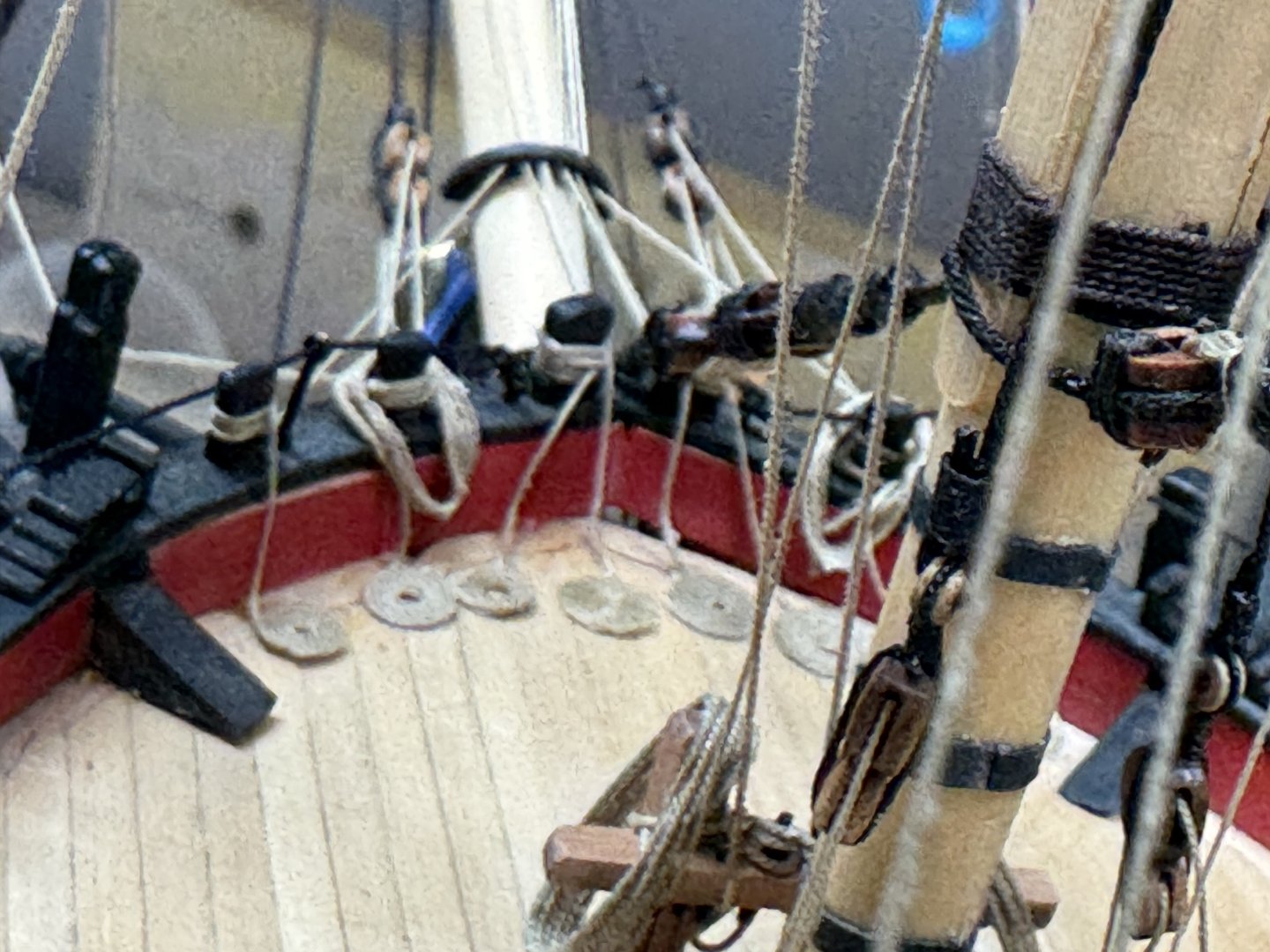
Thanks Thukydides. I have completed the lines going to the two pin rails at the aft end of the forecastle, the knights heads at the bow, the pin rail just aft of the Fore Mast and the Main Topsail Bitts and Gallows. I am continuing to belay the lines to the shroud cleats on the Fore Mast shrouds. It is quite an exercise to get the lines belayed to the cleats from the outside.


- 422 replies
-
- 9
-
-
- Vanguard Models
- Sphinx
- (and 1 more)
-
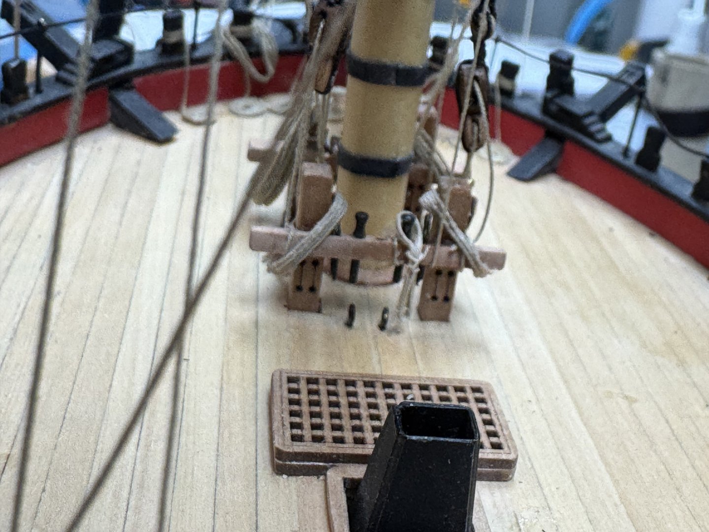
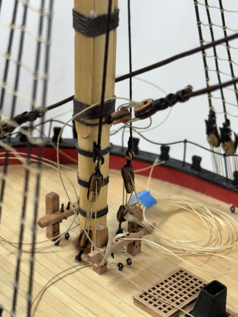
All the lines that need to be run have been (or at least I hope so). Now the task is to tie off the ones (seems like hundreds but is probably more like a few dozen) that are just "holding" and populate the various rigging end points with the appropriate rope coil. I did make a few changes to the belay points on the drawing, most significantly with the fore yard jeers. The drawing shows them belaying at the fore jeer bits behind the fore mast. Since the yard is in front of the mast I changed them to belay at the fore bitts which are forward of the fore mast.. Here is that fore bitts in their completed state.
- 422 replies
-
- 11
-
-
- Vanguard Models
- Sphinx
- (and 1 more)
-
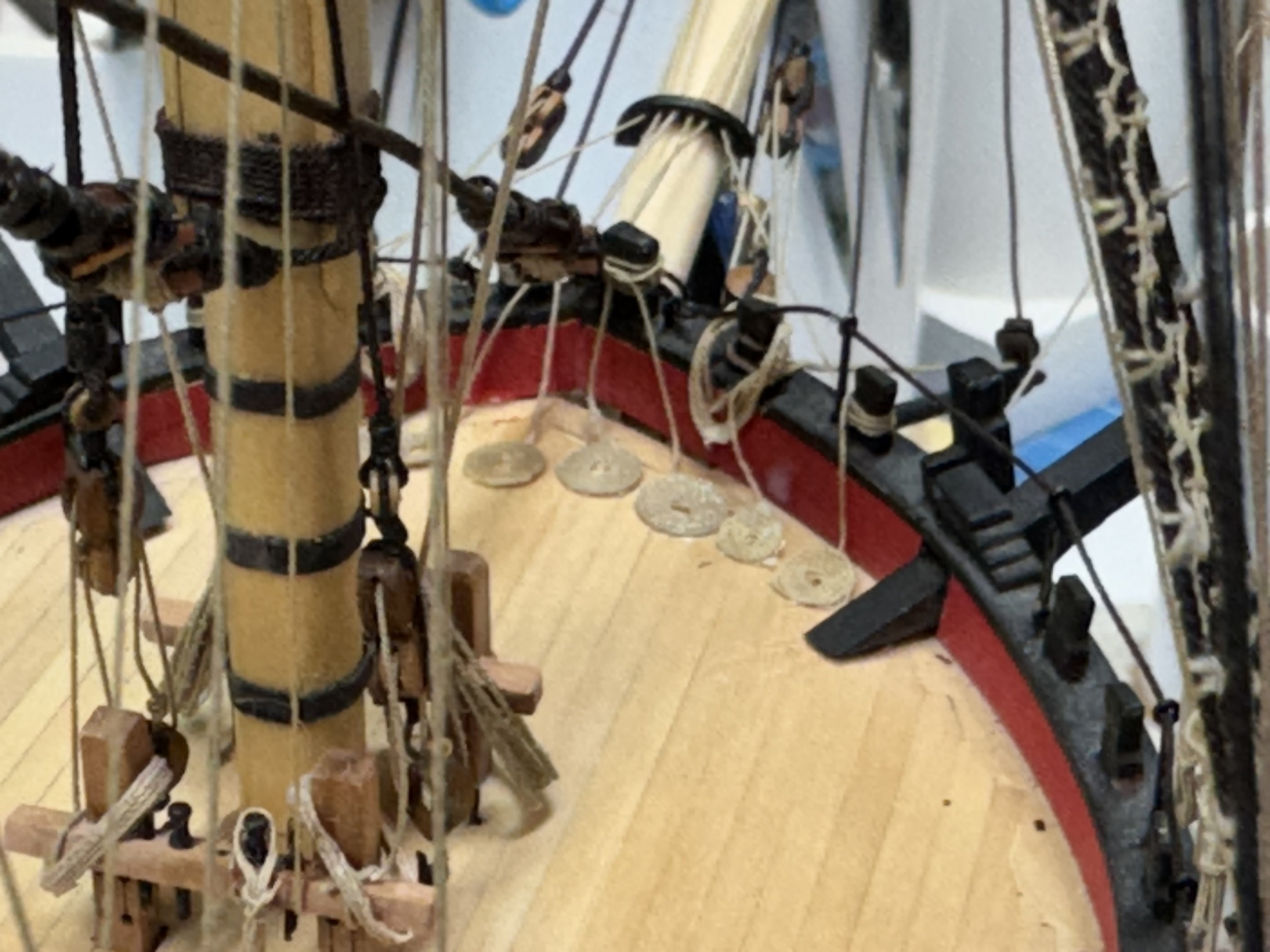
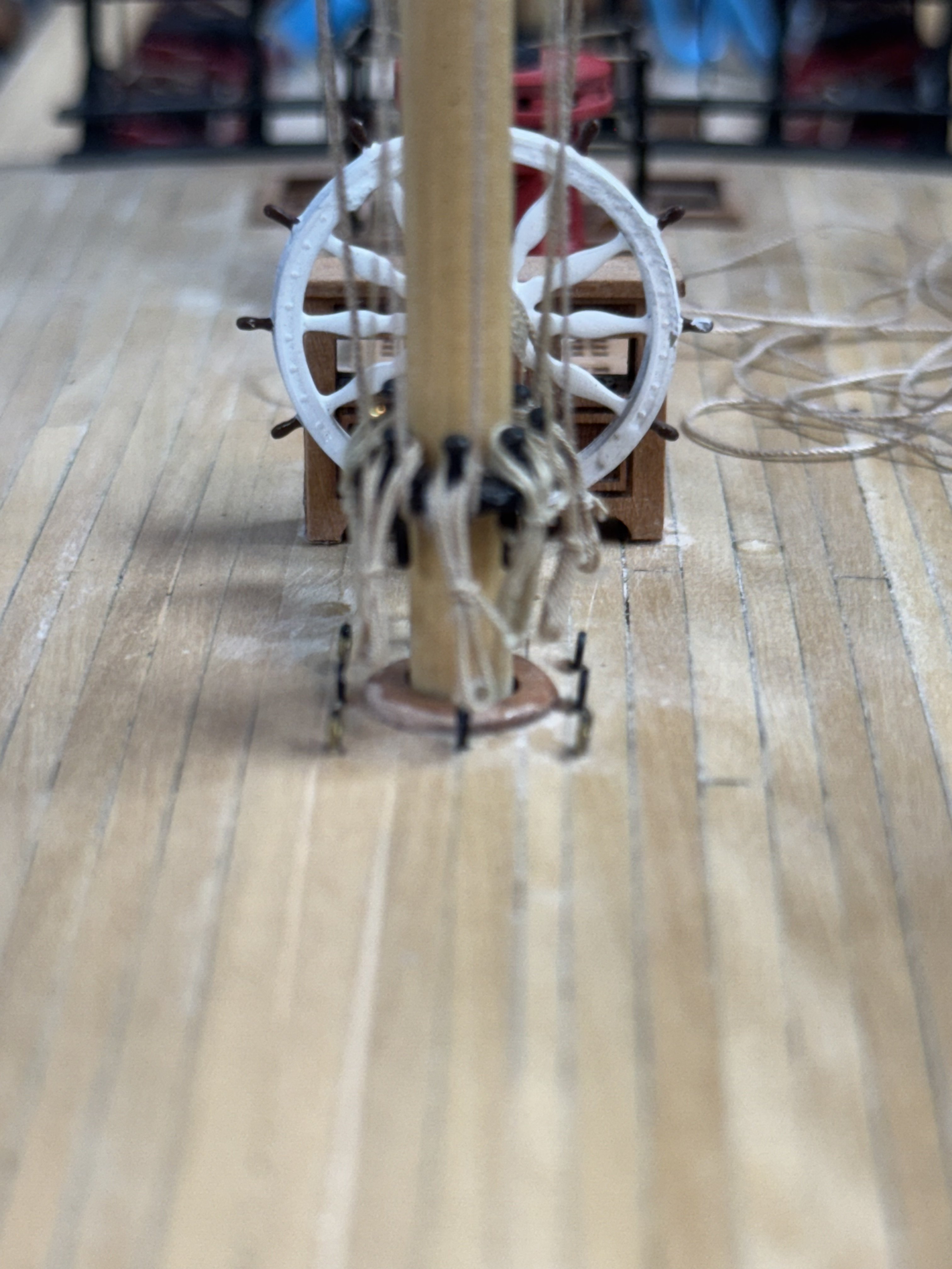
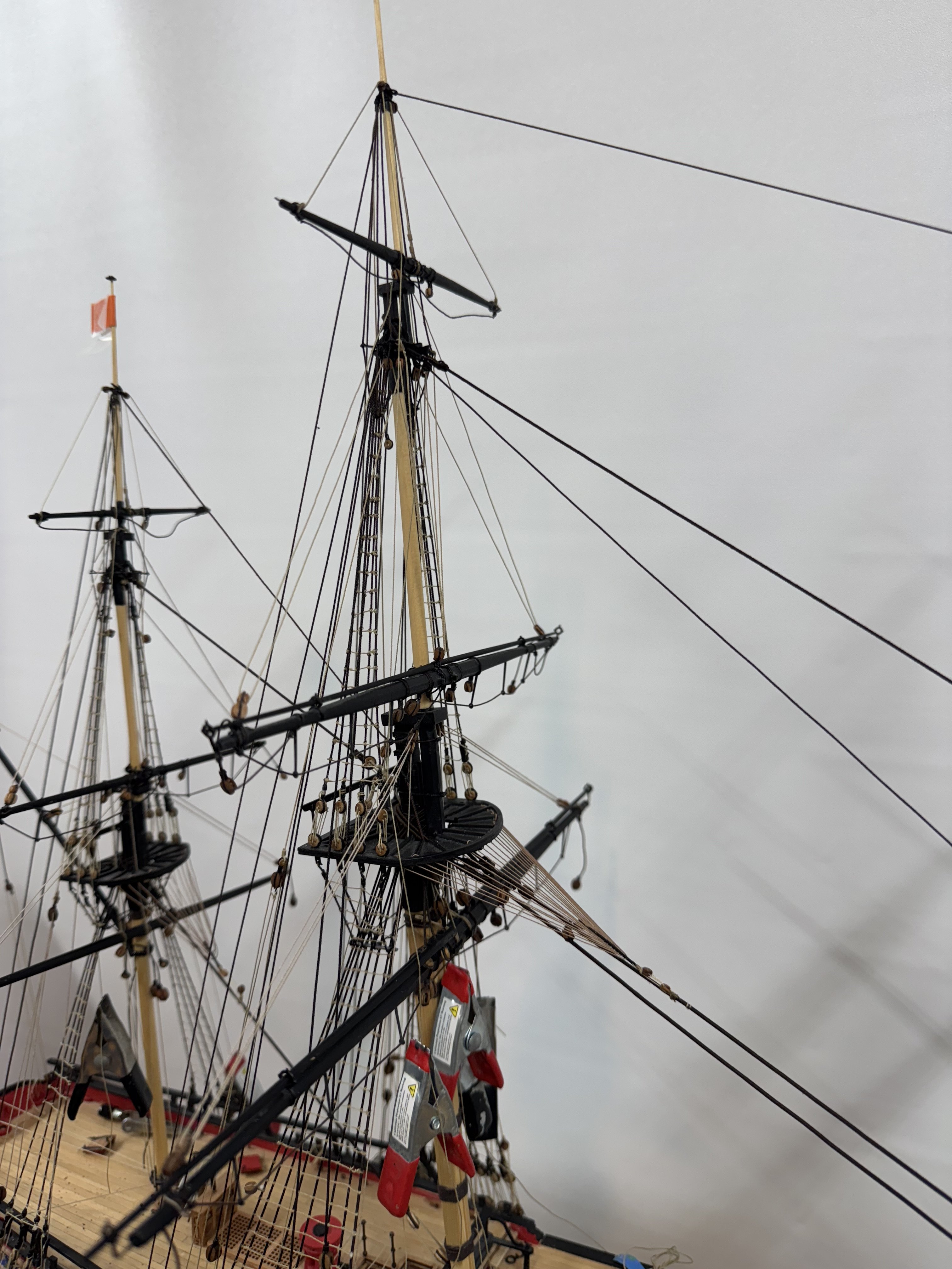
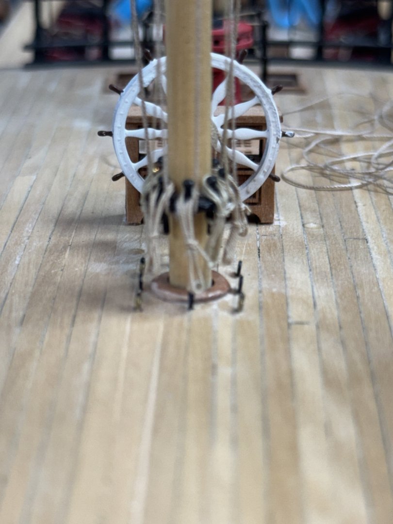
I waited to post again until I had something more or less DONE and now the mizzen mast, gaff and quarter deck are pretty much there. I have all of the mizzen braces, halyards, lifts etc. completed, the ends tied off and rope coils in place. I had not intended to use the round coils which you see at the stern (IMHO they are a pain to make) but the cleats there are so small (and hard to get at AND see what you are doing) that I used coils on the deck for two of the lines on each side. At some point in the distant past I broke off the small cleat in the middle on the port side. I had a few of those cleats left over but estimated my chances of successfully getting it glued on as finite but very, very small so I substituted one of the larger ones and then to keep things symmetrical I broke off the center one on the starboard side and repeated the process. Here is another picture of the mizzen mast The tangle of line is for the main topsail yard braces. The one that terminates at a timberhead rather than a cleat. (Number 63 for those following along). I got all the lines terminated at the mizzen mast pin rack and added rope coils on top to hide the fact that the lines were CAed to the belaying pin and/or pin rack. I also managed to add thew rope around the ship's wheel; not sure how I missed that step but it was only annoying having to work one turn at a time then wait for the H2O/PVA to set, then another turn. I managed to drill holes in the deck approximately where they should be (I think) and glued the ends into the holes. And I added the hammock cranes to the forward end on the qdeck. I had to unrig the mizzen stay deadeye to get the center crane in place. My plan is to add the other hammock cranes and lifelines AFTER all the rigging in the center is finished. They are just too inviting a target and not all that sturdy.


- 422 replies
-
- 10
-
-
- Vanguard Models
- Sphinx
- (and 1 more)
-
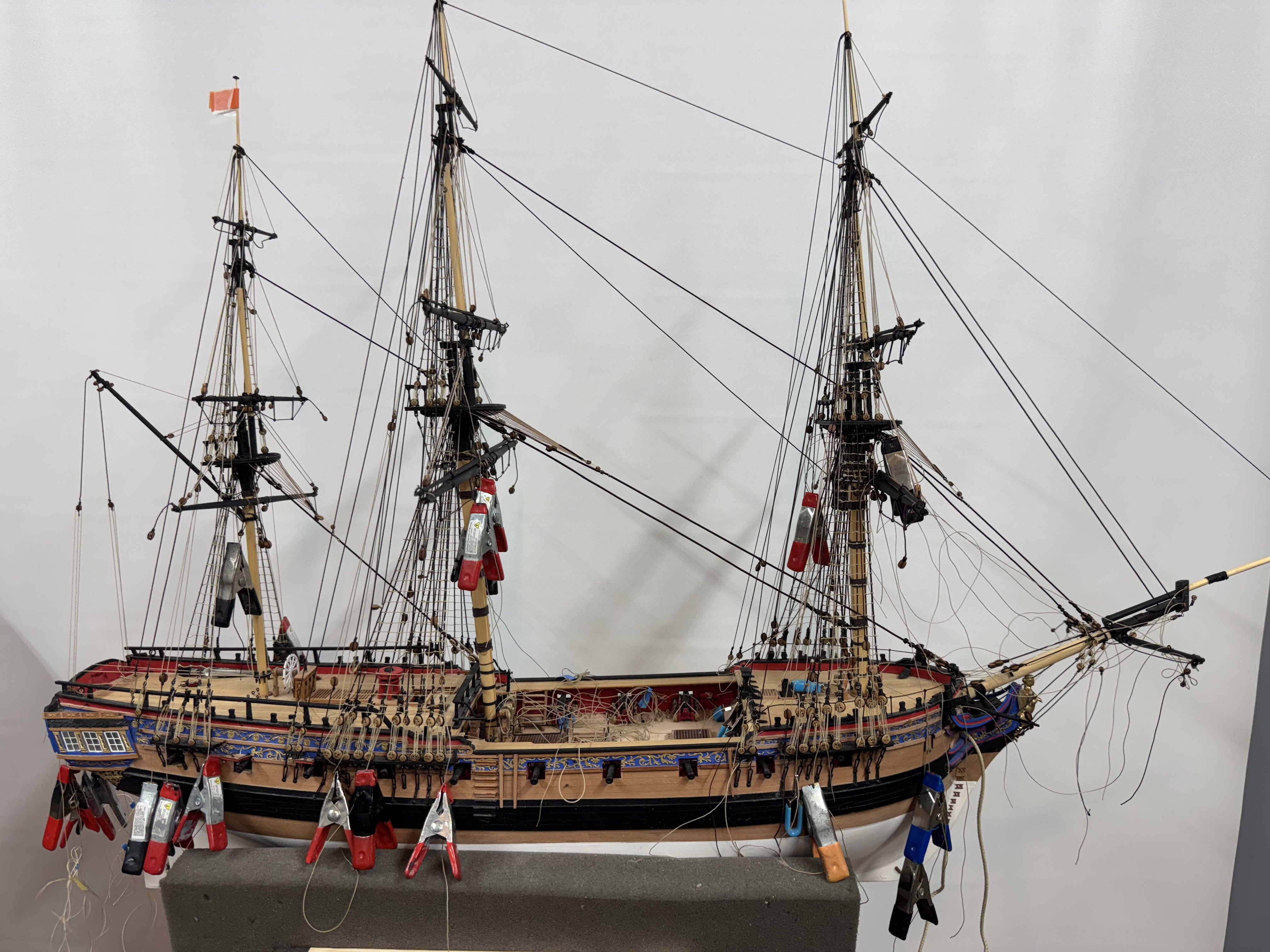
All of the rigging shown on Rigging Plan 3 (except the bow sprit/jib boom) are completed. All the lines have been run to their belay point but not yet secured (hence all the clamps you see hanging about). I am working on trying to find the right jig (I have several from previous builds) to make up the "rope coils" to dress up the belay points (and hide any shortcuts (like CA instead of a "proper" securing) but so far there are so many different types I may have to create some additional templates. The very limited space on the shroud cleats is one area where I do not have anything that will work. On the fore and main I had to remove the blocks under the cross trees and add them further outboard on the cross trees in order to get the lines (topsail lifts) to them. As I originally installed them they were "embedded" in the tops of the topmast shrouds and I would had a devil of a time trying to thread a line through them. Aside from those issues everything went "according to plan" except the gaff lift. The plan shows two double blocks with the standing end on the lower block becket and the bitter end going down from the upper block to the pin rail at the base of the mizzen. As best I can tell this "misses" one of the sheaves on the lower block. I just ignored the problem and left the other lower block sheave empty. It is pretty hard to see under the mizzen platform. I was so close to finishing the mizzen I was not up for moving the standing end to the top or replacing the lower with a single.


- 422 replies
-
- 7
-
-
- Vanguard Models
- Sphinx
- (and 1 more)
-
I obviously can't read a drawing but as Thukydides mentions it was up to the commander whether or not the tar the ratlines. I think the lighter color avoids the shroud/ratlines looking like a spider's web. Fritz - that must be a typo on the drawing should be .1mm not .01mm. As you point out that would way too small.
- 422 replies
-
- 2
-
-
- Vanguard Models
- Sphinx
- (and 1 more)
-
Fritz, In Daivd Antscherl's book on rigging the Swan Class Sixth rater he says the fore and main ratlines are 1.5" and the mizzen 1". I think that in general line sizes are circumference not diameter so at 1/64 scale and in diameter that would be about (using 3.0 for pi to allow my math skills to work) then the 1.5" line would be .5" diameter at full size and .0078" at 1/64th. That book also states that the ratlines were tarred which was not the case in the Sphinx kit as the tan line was specified for the ratlines. I used Syren Ultra tan in the .008" (aka .2mm) size which is twice the size called out in the plans on all three masts. I found the .1mm 100% polyester line supplied with the kit more difficult to work with. I am surprised that the ratline size would vary from mast to mast unless only the smaller lighter sailors were top men on the mizzen mast.
- 422 replies
-
- 1
-
-
- Vanguard Models
- Sphinx
- (and 1 more)
-
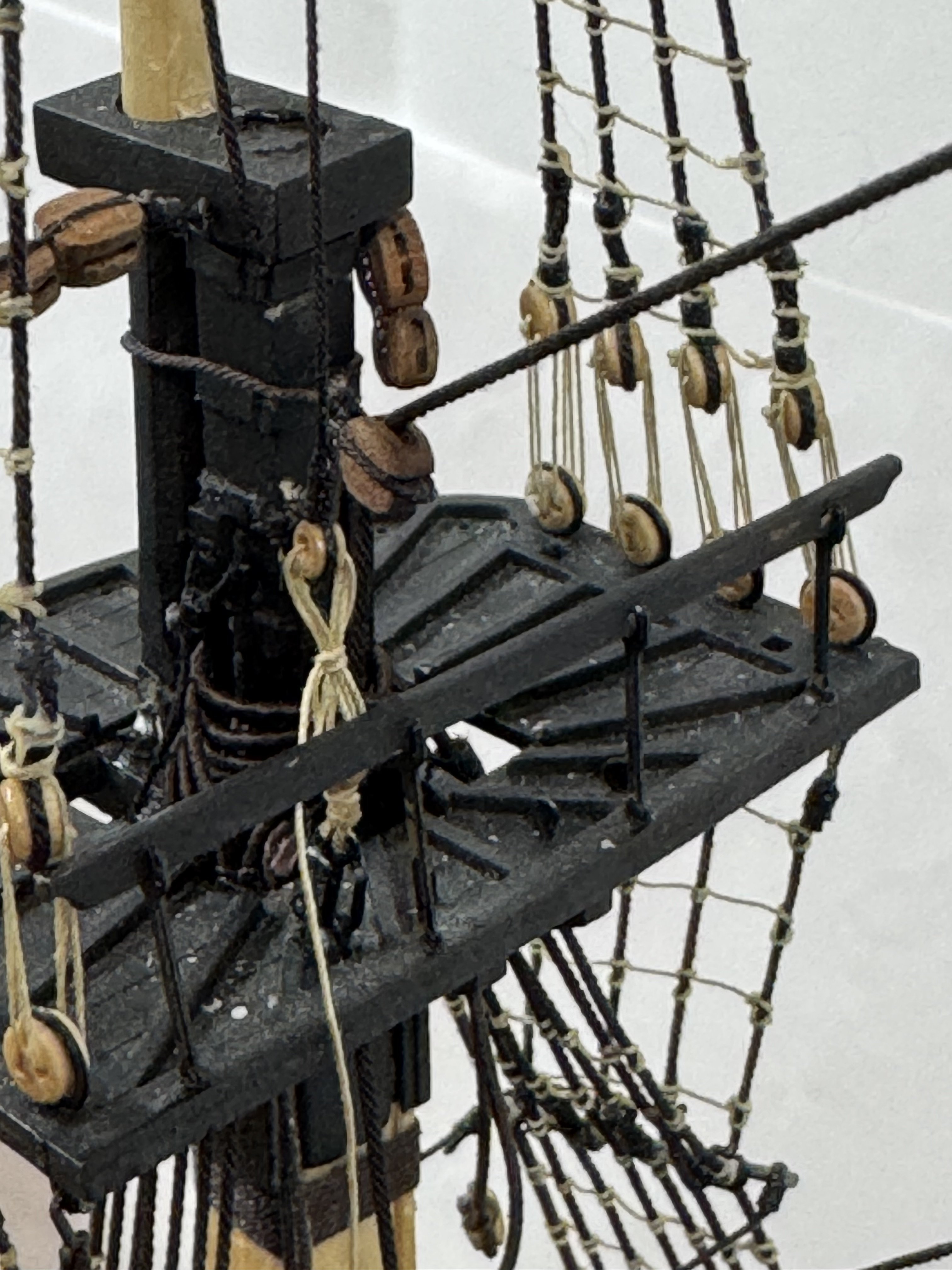
Lifts/halyards on all three fore mast yards completed. Lines are all terminated with weights (clamps) for now. Moving on to main mast yards starting at the top as I did on the fore -mseemed easier to stay out of my own way but I will not have as convenient assess from the front on the main. One item I had to correct was the lift blocks for the fore yard on the mast. Instead of using bridles around the top mast I used eyebolts in the mast cap - then I apparently put the mast cap on backwards (hard to tell since the hole sizes are almost identical) - had to cut the old ones off and fab new ones to mount on mast cap along side the topsail mast. Would have been really "fun" trying to weave the lift lines through the shrouds/ratlines with the blocks in the old position..

- 422 replies
-
- 5
-
-
- Vanguard Models
- Sphinx
- (and 1 more)
-
The fore topgallant and topsail yards are in place with the lifts and halyards reeved and taken to there belay points but not yet secured. The alligator clip is holding the other lines at bay while I rigged the fore yard lifts. The fore yards is just "hanging there at the moment. I thought it better to rig the lifts before securing the yard to the mast. Quite the rats nest. This mast is worse than the main since it has the braces and such from the sprit sails running though under the fore platformas well at the lifts and such for the fore yard. (I keep telling myself that things will get easier.) Here is the fore topgallant yard in place. And the fore topsail yard. I have the repaired jib boom in place and the spirt topsail yard "just hanging there" for now. The more flex it has the less likely an errant elbow or wrist will knock it off again. I will revisit the bowsprit after I get the masts done.


- 422 replies
-
- 4
-
-
- Vanguard Models
- Sphinx
- (and 1 more)
-
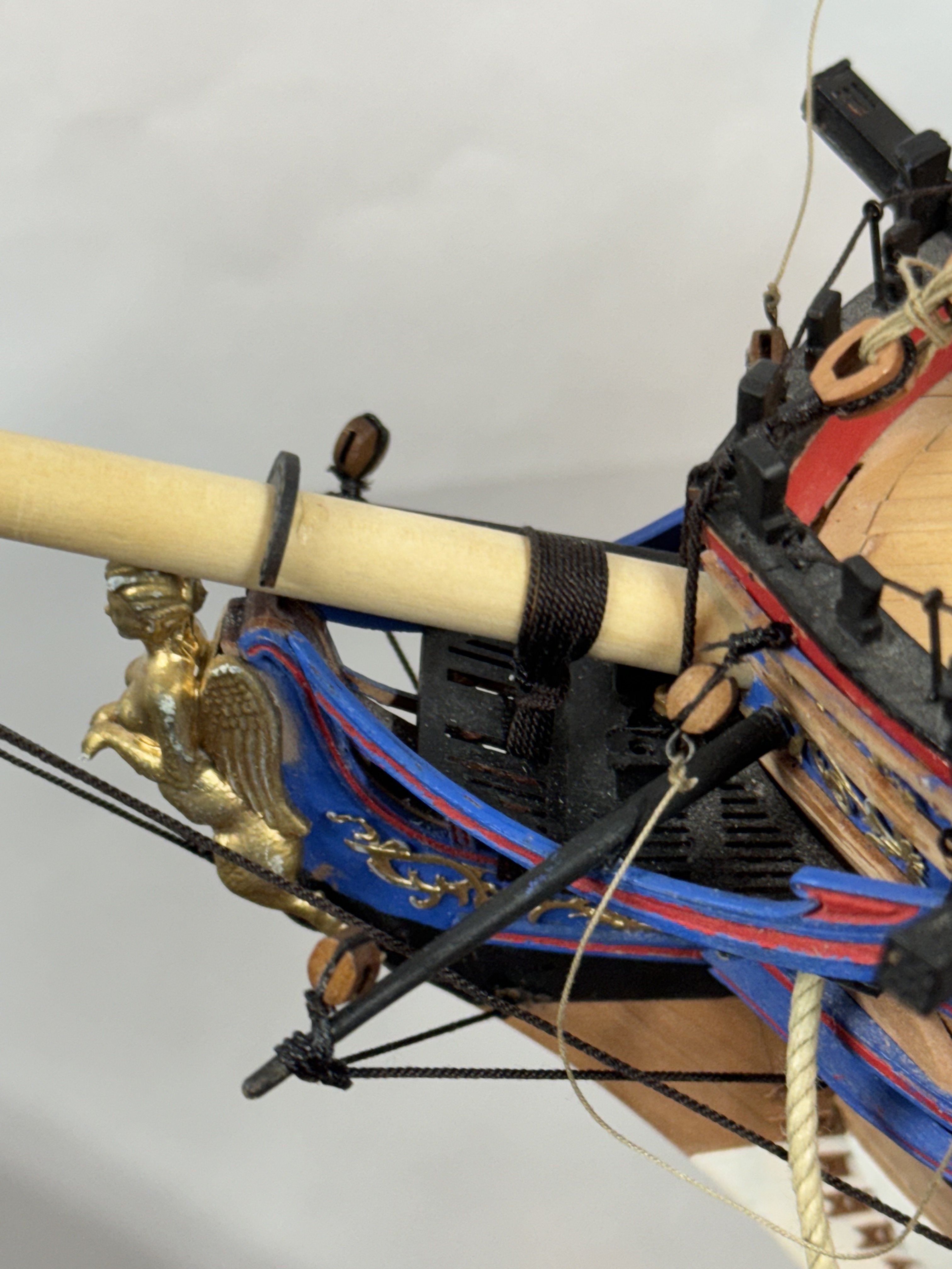
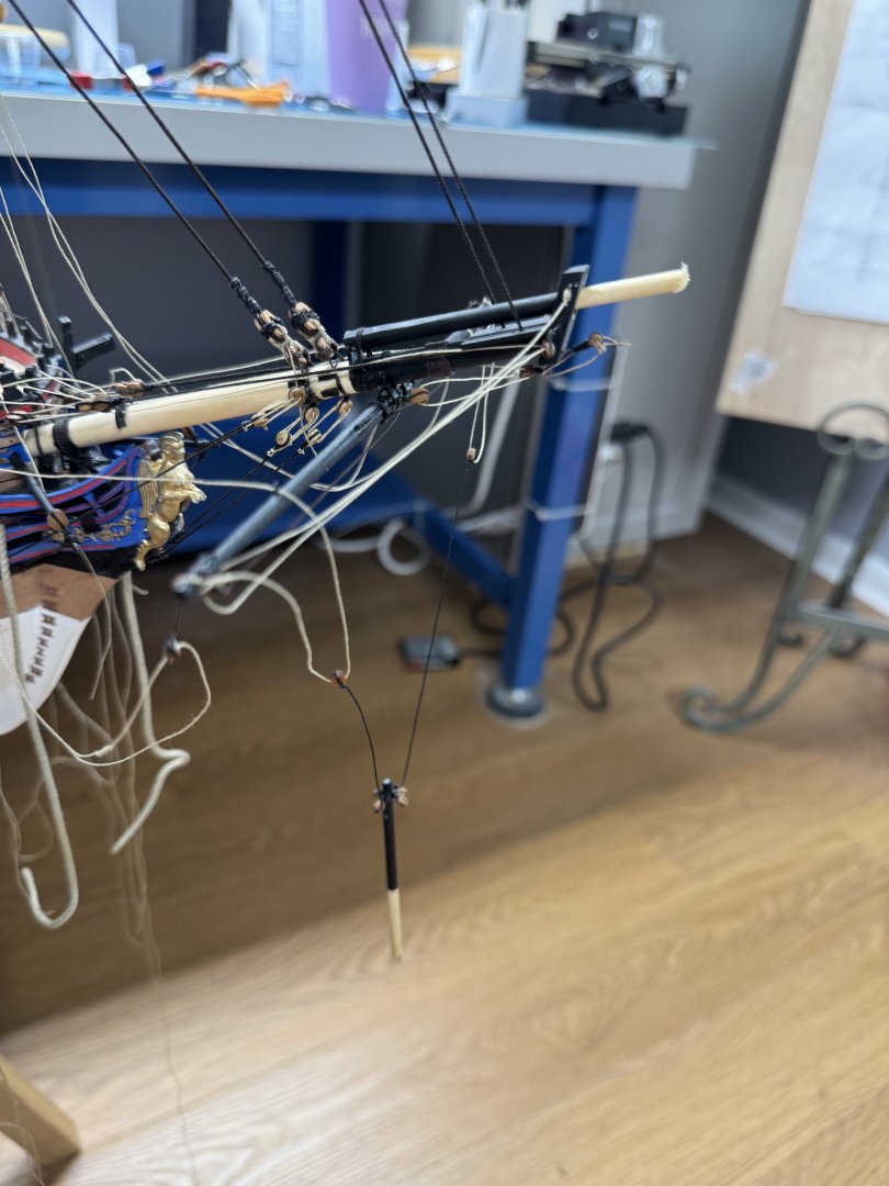
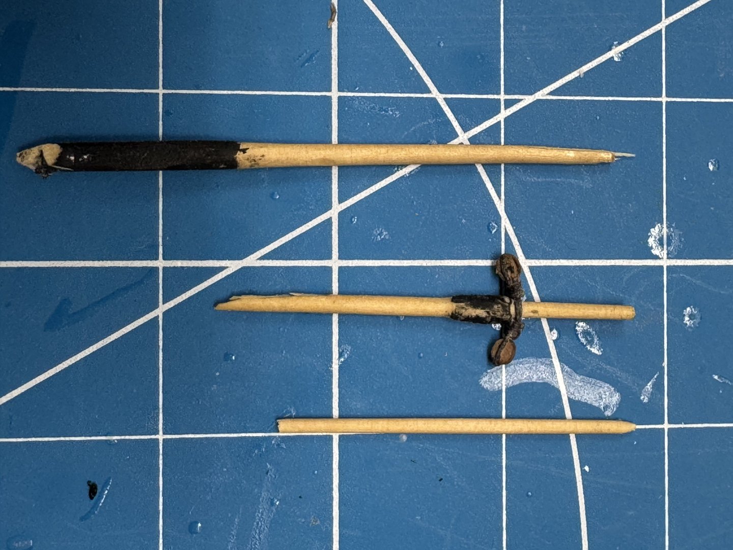
I guess both good and bad things come in threes. I broke the mizzen and fore top gallant masts and now the jib boom. It broke just at the hole where the sprit topsail yard was installed. An obvious weak point. This is the "scene of the crime" after I cleared away most of the "wreckage". I flattened off the two ends of the jib boom, drilled a #60 hole in the center (hopefully) of each end and fit them back together with a .040 phosphor-bronze pin inserted into both ends. A few drops of thin CA and a stand in for the fore top gallant stay to keep the two pieces aligned vertically and let the CA set. I plan on wrapping the affected area in .012 dark brown line to add some additional support. How the sprit topsail yard gets attached is TBD for now but a hole and pin is NOT in the plan..

- 422 replies
-
- 6
-
-
- Vanguard Models
- Sphinx
- (and 1 more)
-
I completed all of the rigging shown on Rigging Sheet 2. Then I added the Spritsail and Sprit topsail yards to the bowsprit and jib boom. I followed the instructions and used small (.032" music wire) pins to hold the yards to the jib boom and bow sprit. If I had it to do over again I would put the pin on the ship not the yard. I had the devils own time trying to "find the hole" and get the yard seated correctly. I used five minute epoxy to attempt a "secure" bond. After the glue dried I fashioned the slings for the yards and glued them in place with CA. Hopefully nothing will fall off between now and completion. With the two yards in place I finished the rigging shown on Rigging sheet 2 and the rigging for the bowsprit and jib boom shown on Rigging Sheet 3. Then I began to contemplate what to do next. Looking at Rigging sheets 3 and 4 I noted that the braces for the two bowsprit yards run through double blocks, two on each side under the foremast platform. Figuring that this is the most uncluttered time to try and run lines through these blocks I secured the two spritsail braces to the fore main stay collar (or thereabouts) and ran them through the blocks on the yard, through the two sets of block and down to the pin rail at the aft end of the forecastle. I ran the sprit topsail braces similarly. I left enough extra line in place so these can be out of the way while getting the fore yard in place. I also added the lines for the fore yard lifts as they start at the two double blocks also under the fore platform. I am tempted to start at the top of the foremast adding the yards and rigging moving down rather than add all the yards and then start rigging the halyards lifts and braces.


- 422 replies
-
- 7
-
-
- Vanguard Models
- Sphinx
- (and 1 more)
-
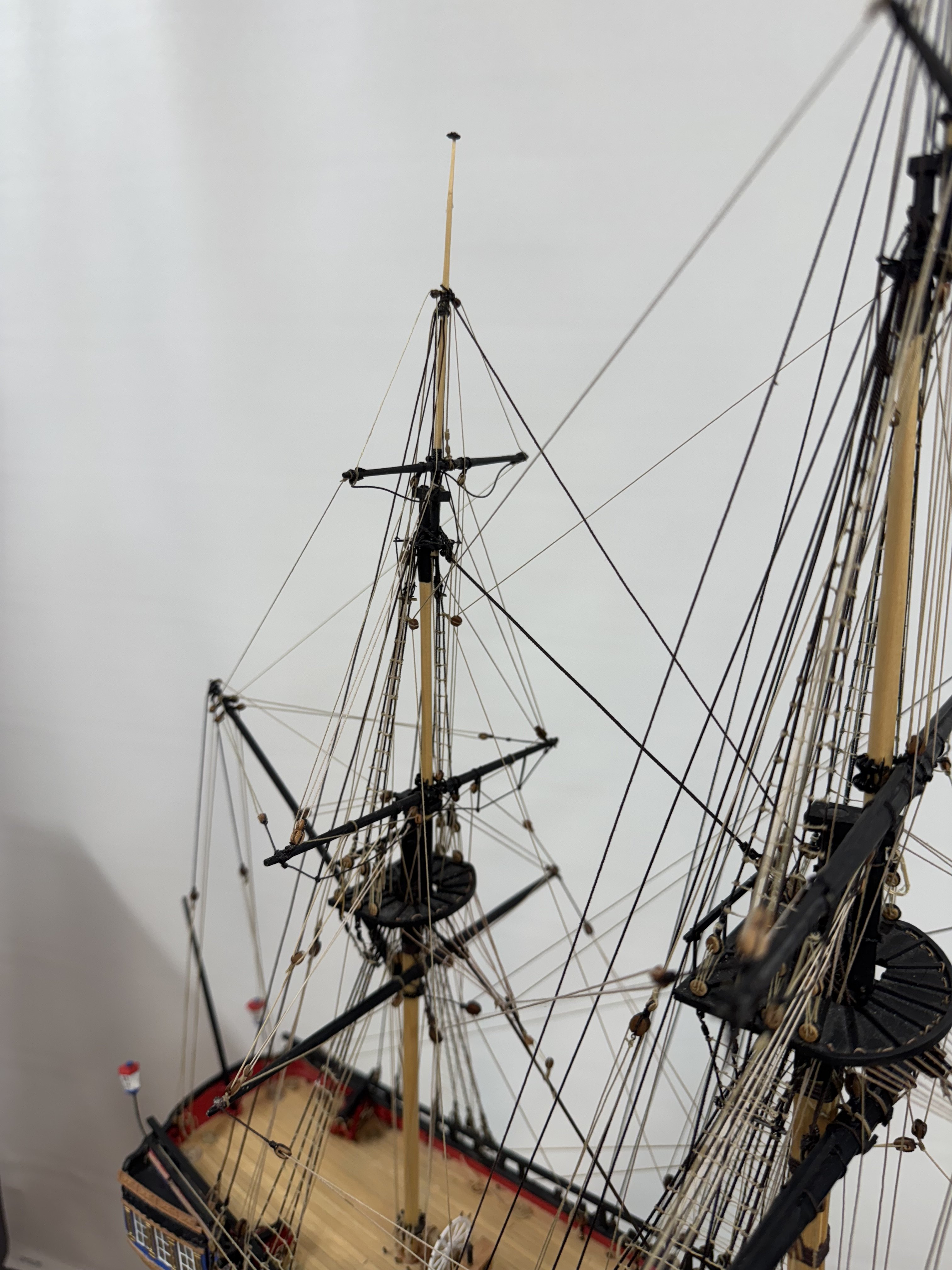
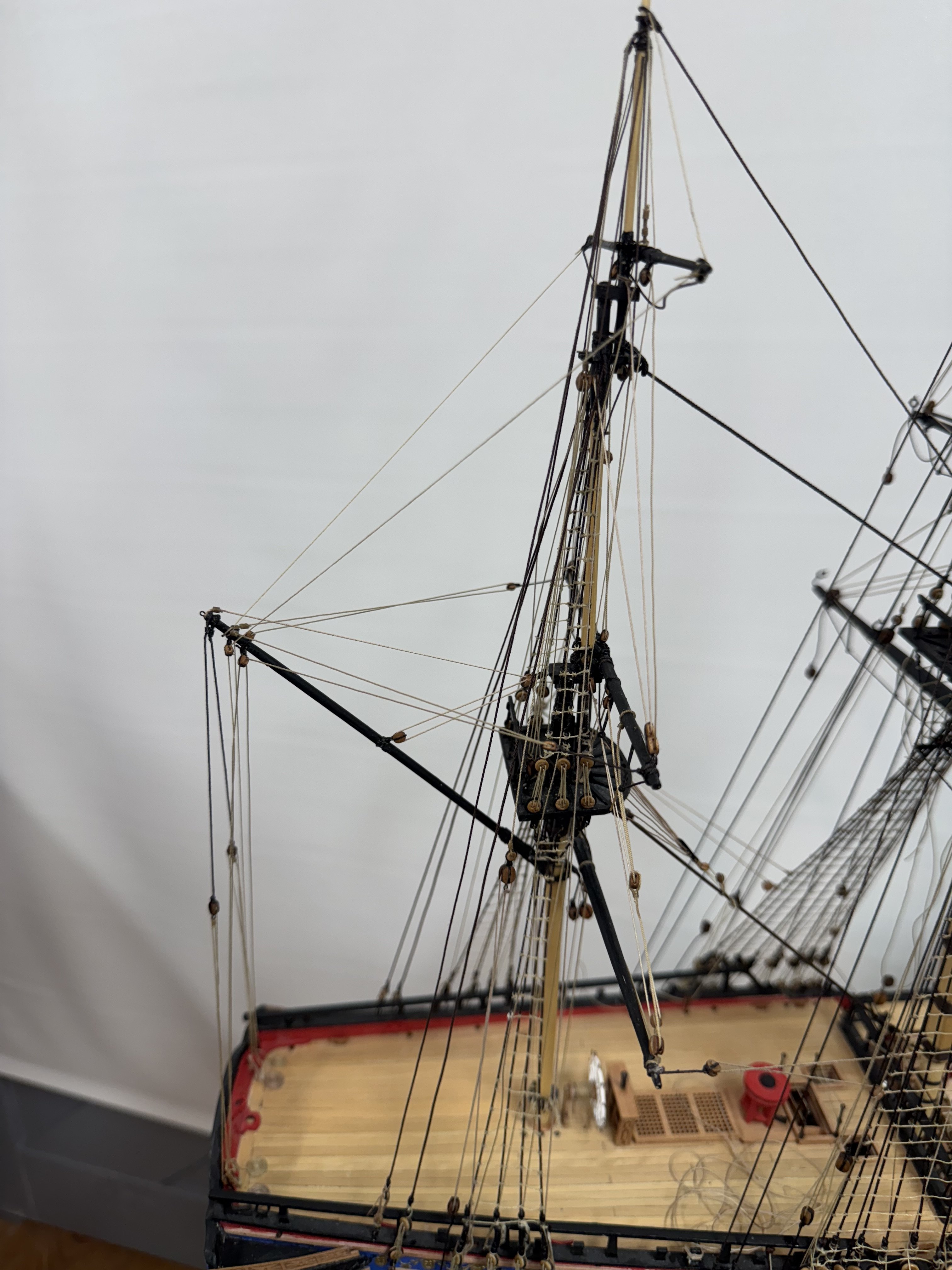
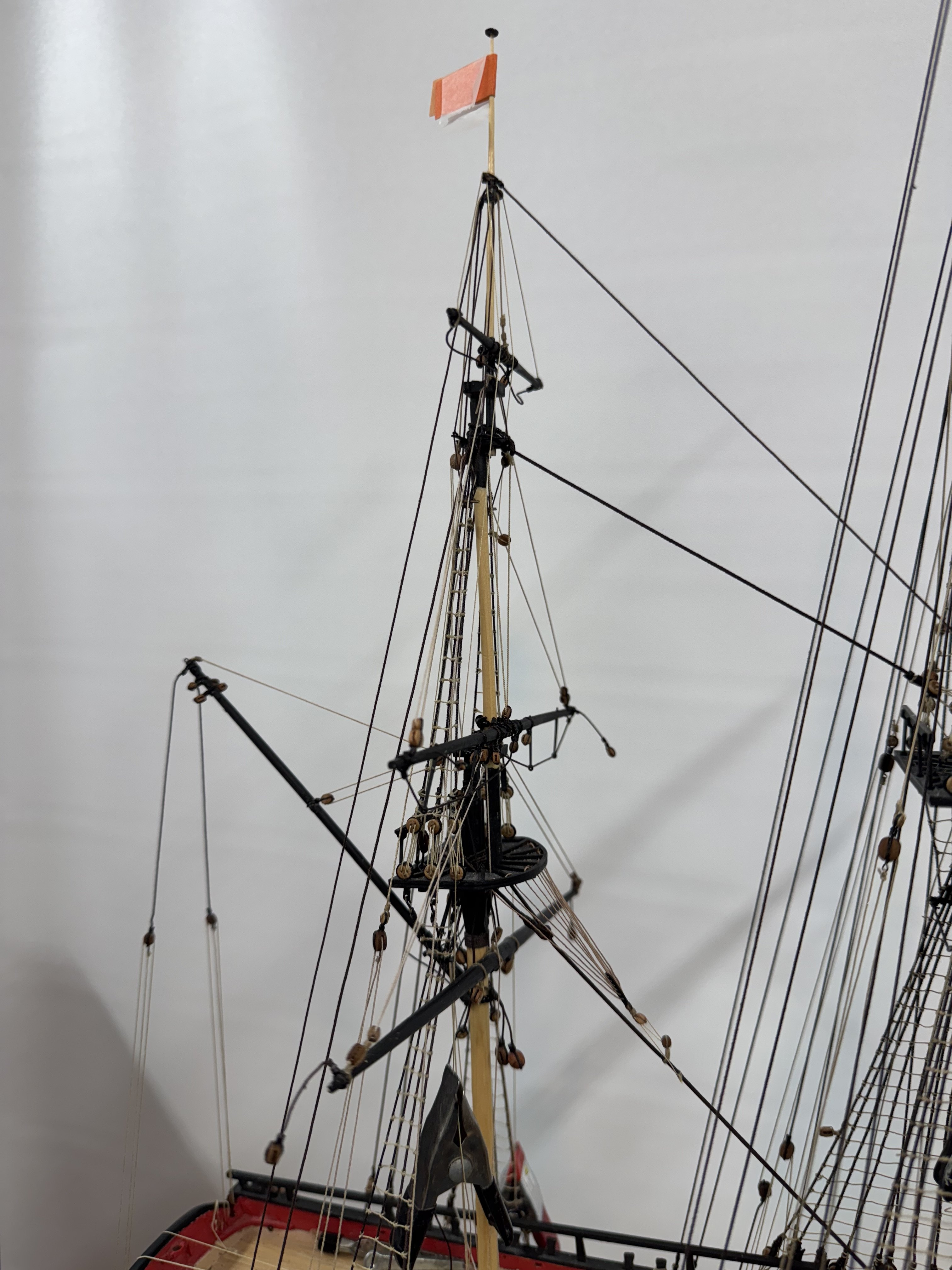
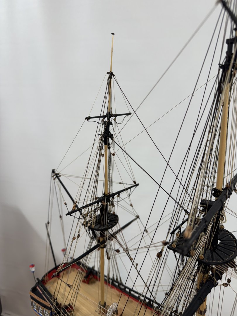
All the back stays are now complete. I tied off the deadeye lanyards but have not "secured" them yet "just in case" I need to tighten or loosen something as the fore mast rigging progresses. As you can see the main top gallant stay looks a little slack here. Hopefully the fore top mast (or top gallant) stays will "take up the slack". Which means that the fore mast crowfeet are next since I do not want to have the fore top mast stays in the way trying to thread the crowsfeet. Here is the model is it stands now and close-ups of the fore mast backstays areas.

- 422 replies
-
- 6
-
-
- Vanguard Models
- Sphinx
- (and 1 more)
-
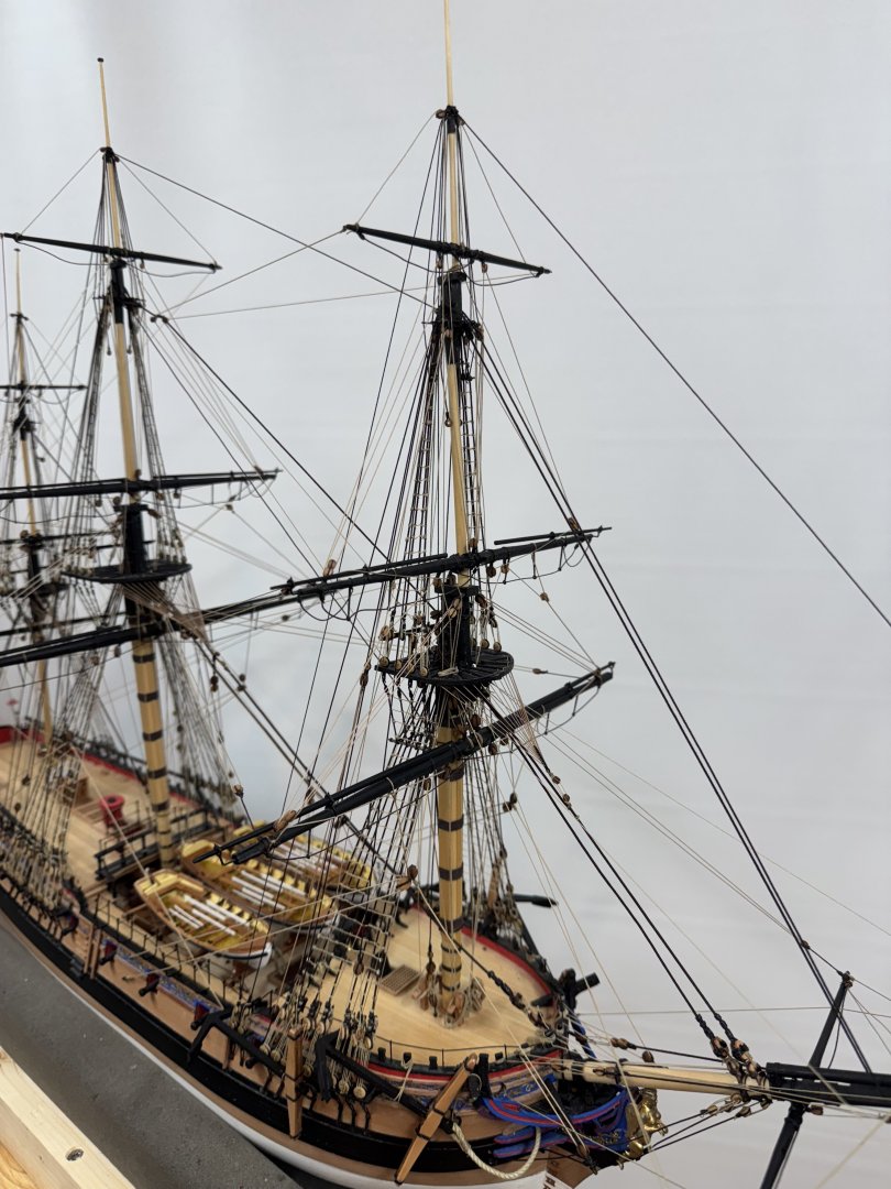
Thanks TJ and Tim - as you can see I have incorporated both suggestions. But not before I snapped off the fore top gallant mast into three pieces. I did not attempt to repair this one - cut down/removed the shrouds and fabricated a replacement which is now ready for rigging the back stays (which I sorta forgot some where along the way). While neglecting the back stays I did manage to get the fore and preventer stays in place. While doing that I noticed that in my hurry to move along I neglected to include the lashings on the sides of the closed hearts on the main and main preventer stays so that was one more thing I had to fix. After a couple of tries doing it with the main preventer in place I finally gave up and cut the lanyards, removed the heart from the fore mast and added the lashings then reinstalled everything. Now on to the fore mast back stays.


- 422 replies
-
- 6
-
-
- Vanguard Models
- Sphinx
- (and 1 more)
-
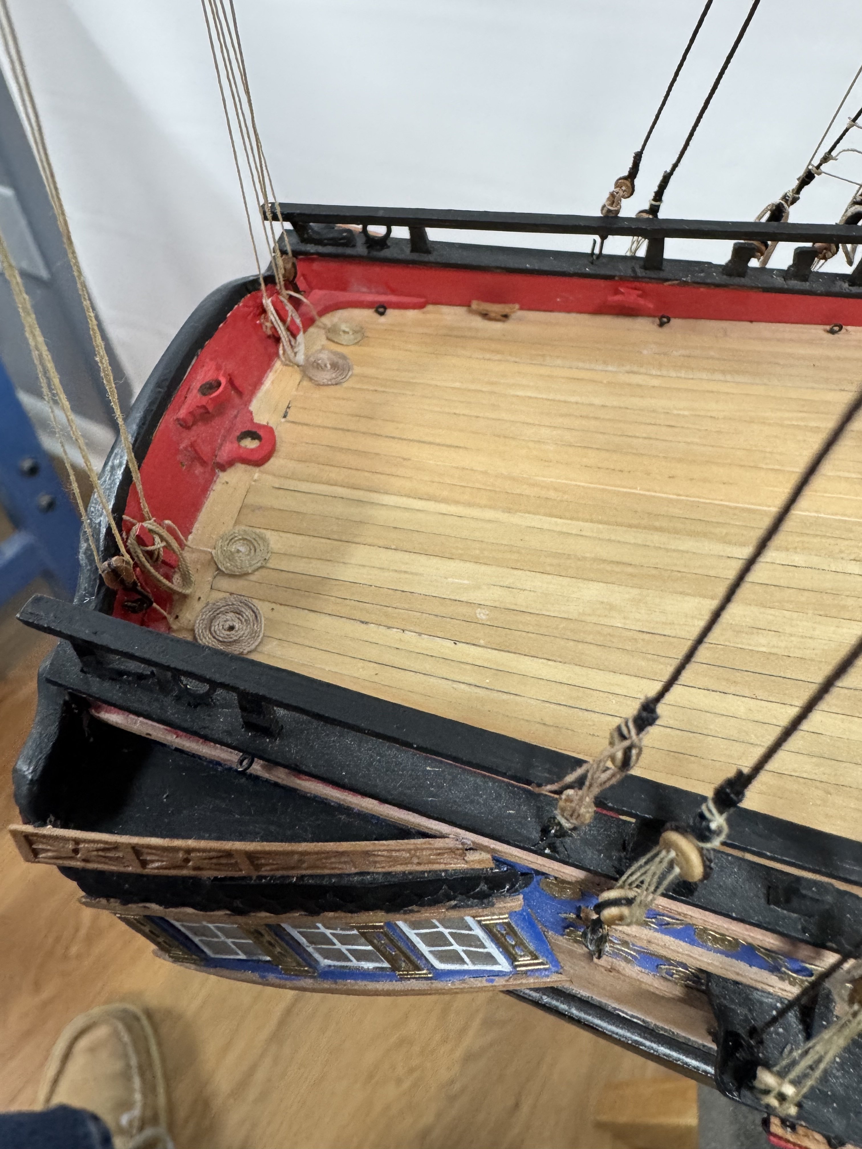
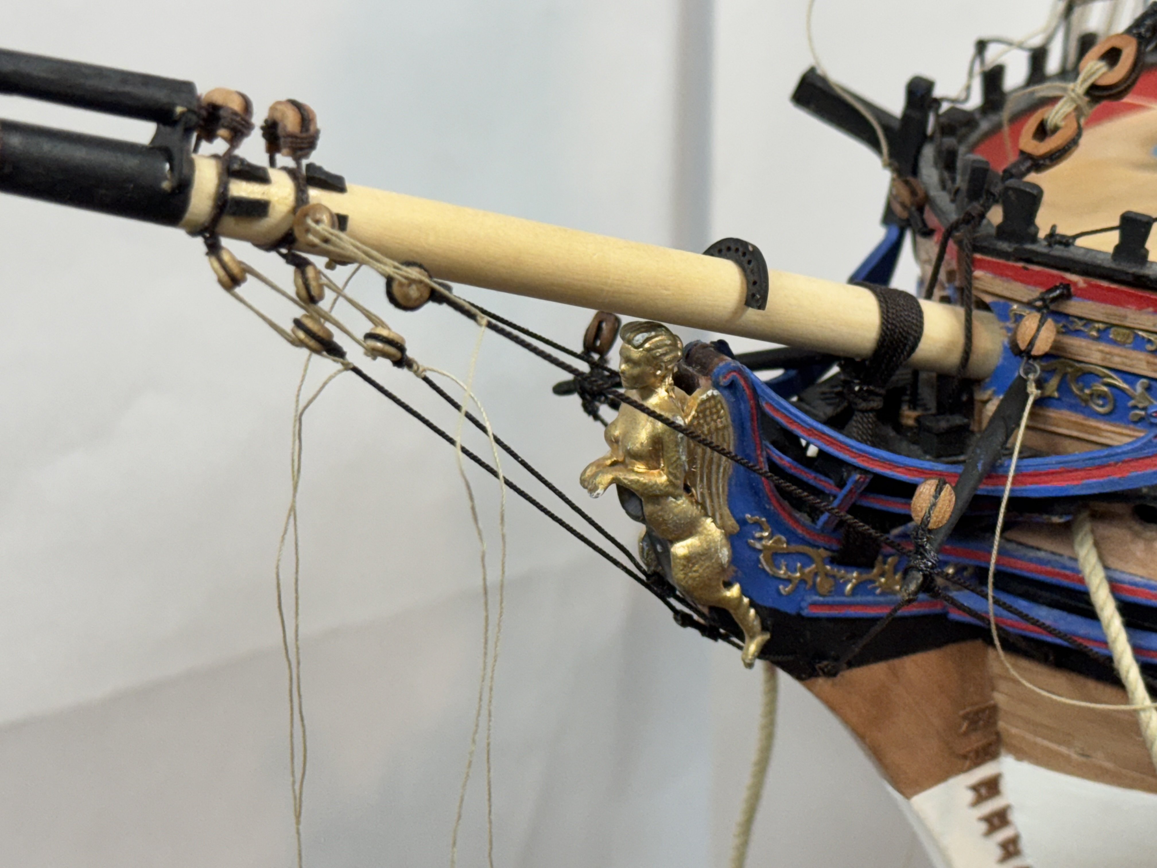
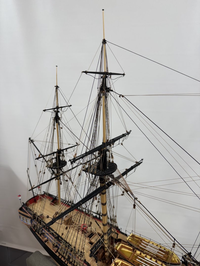
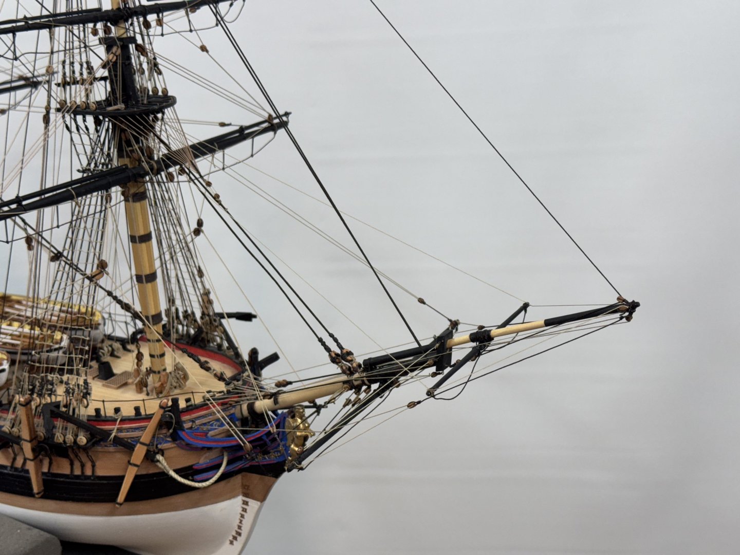
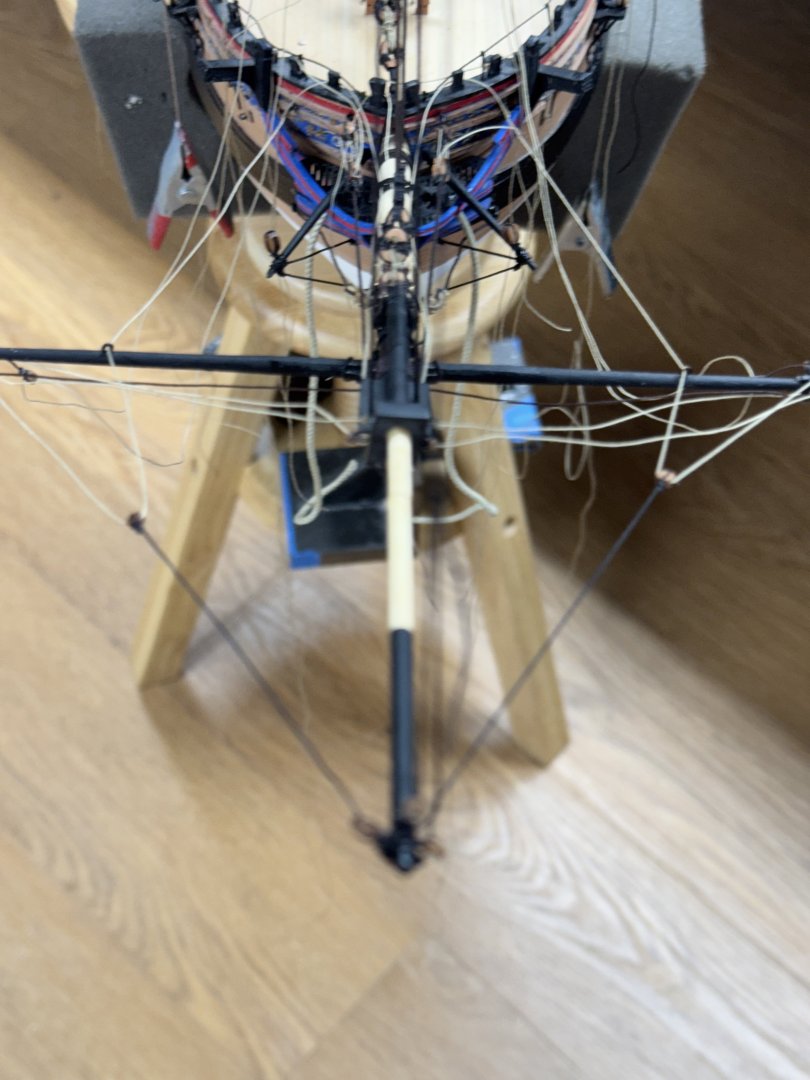
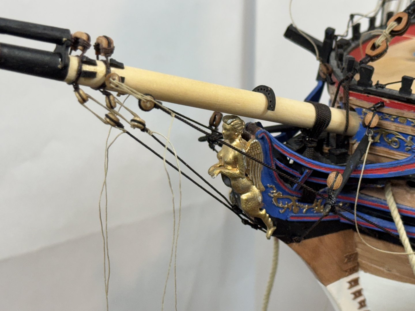
It is beginning to look like a ship! I installed the remaining main stays (Top Mast, Top Mast Preventer and Top Gallant mast). No issues aside from having to work around the shrouds, ratlines etc. Here are the tackle ends on the three upper main mast stays. I have not yet secured the lanyards for the main preventer stay. I seized a small thimble above the double block at the top to provide a convenient place to terminate the stays. And then the moment I have been dreading for a good bit - adding the bowsprit/jib boom. Such an inviting target for wayward elbows, shirt sleeves etc. But I can't add the fore mast stays without so - "Let's be particularly careful from here on". I did the gammoning first but not before I had to undo the boomkin stays as they really got in my way rigging the gammoning, I needed about 1.5" of CA hardened end on the 0.25" Syren Ultra Brown line so I could tread it through the slots in the bow platform floor and find the other end. I also rigged the four bowsprit stays which took a bit of effort trying to thread the deadeyes since I seemed invariably to be on the wrong side when trying to tread the deadeyes. Lanyards have not yet been treated with 60/40 PVA water but that is next. And here is the model as it stands now Not sure the back of the plans is any better than the grey door. I am looking to buy some white poster board to make a better background.


- 422 replies
-
- 8
-
-
- Vanguard Models
- Sphinx
- (and 1 more)