HOLIDAY DONATION DRIVE - SUPPORT MSW - DO YOUR PART TO KEEP THIS GREAT FORUM GOING! (Only 13 donations so far - C'mon guys!)
×


cdrusn89
-
Posts
1,915 -
Joined
-
Last visited
Content Type
Profiles
Forums
Gallery
Events
Everything posted by cdrusn89
-
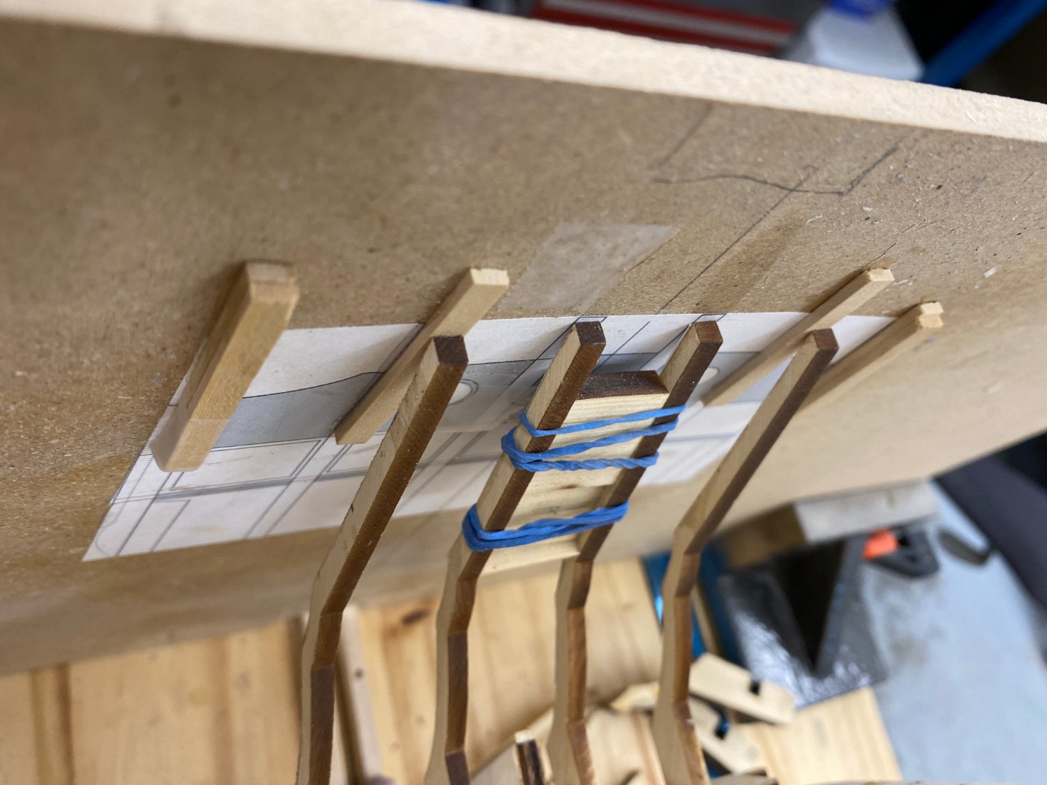
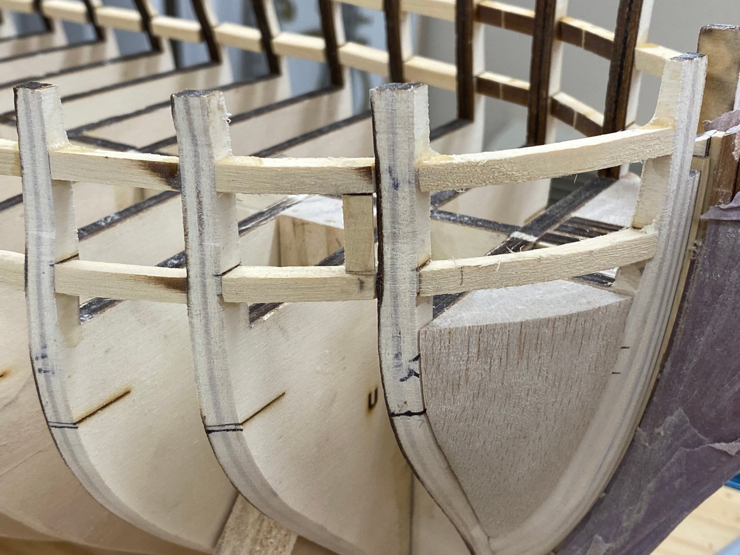
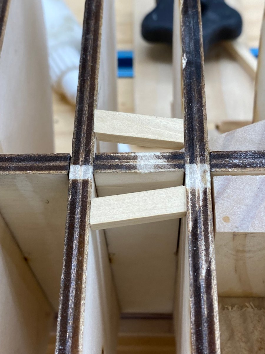
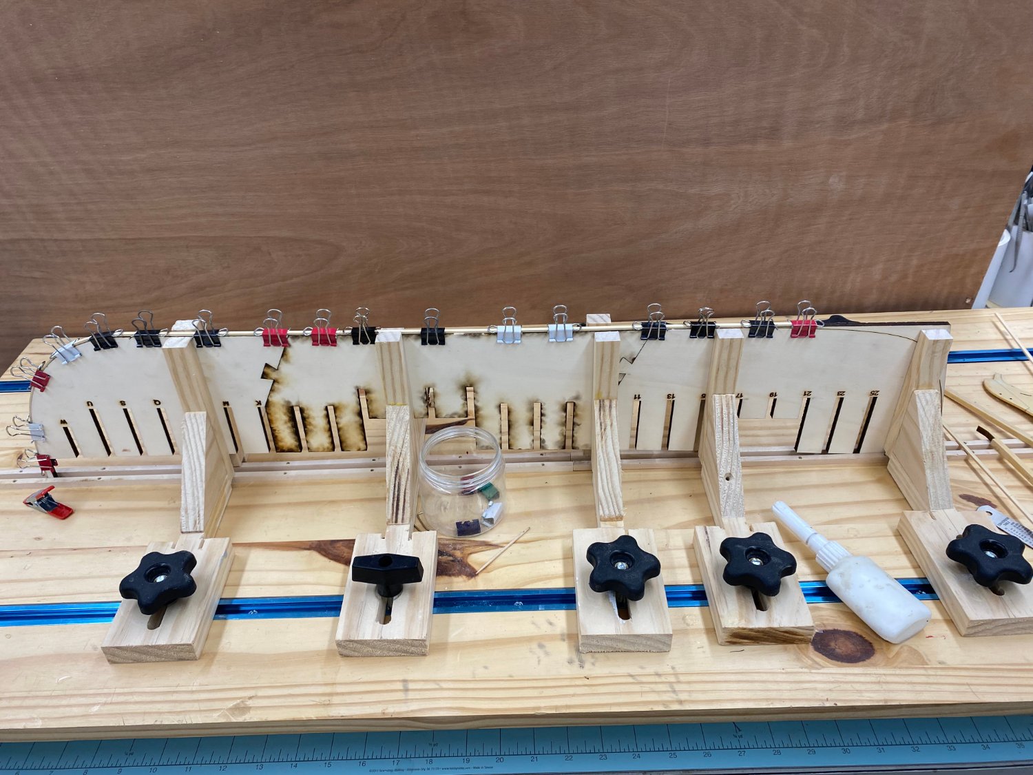
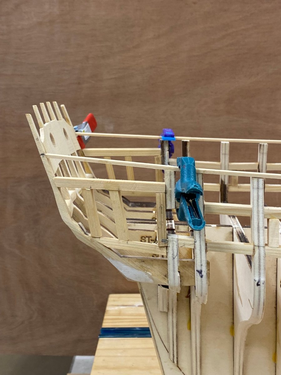
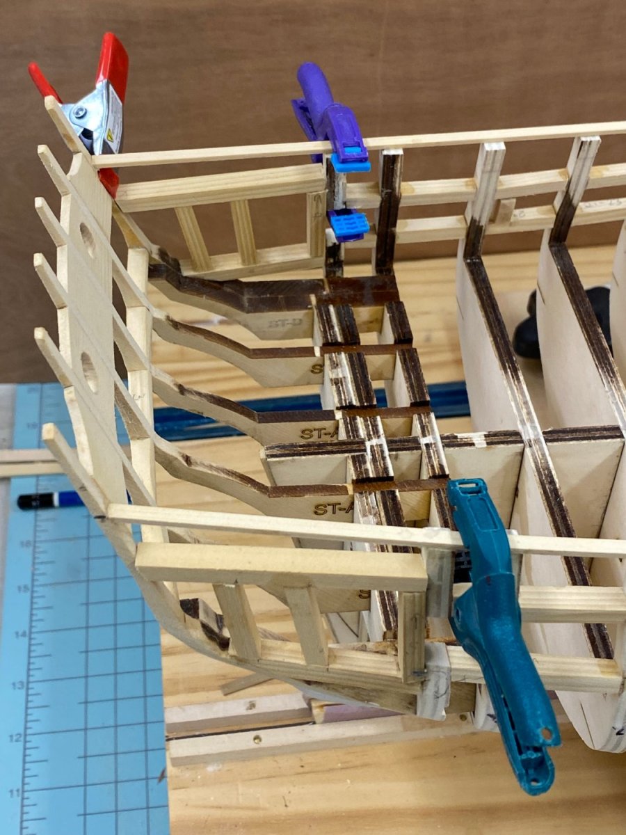
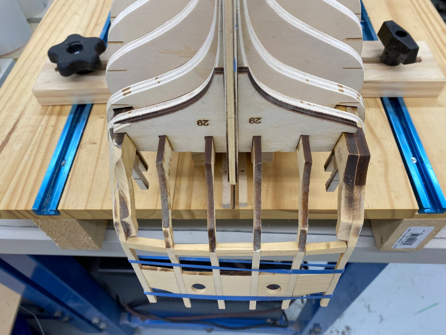
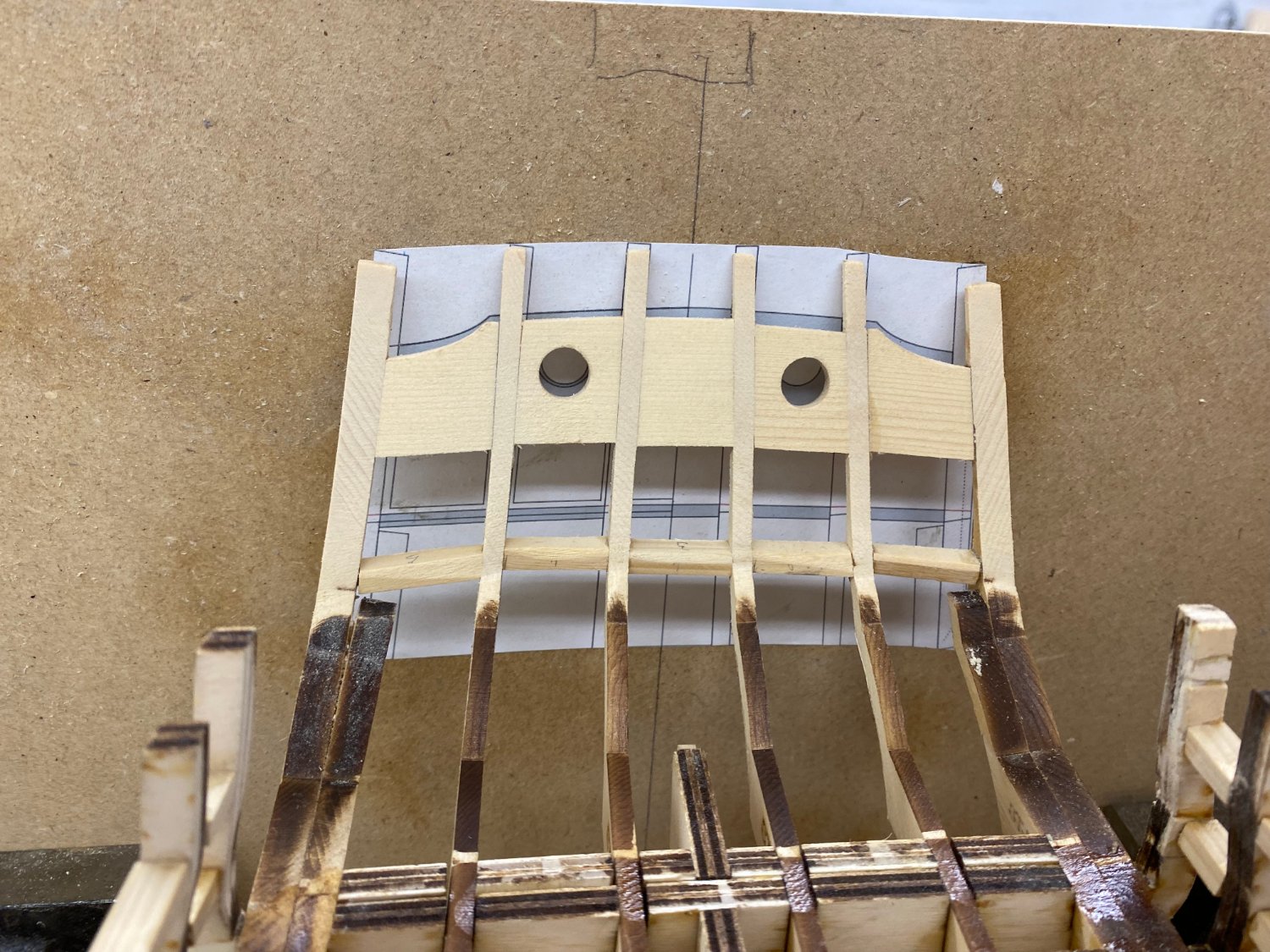
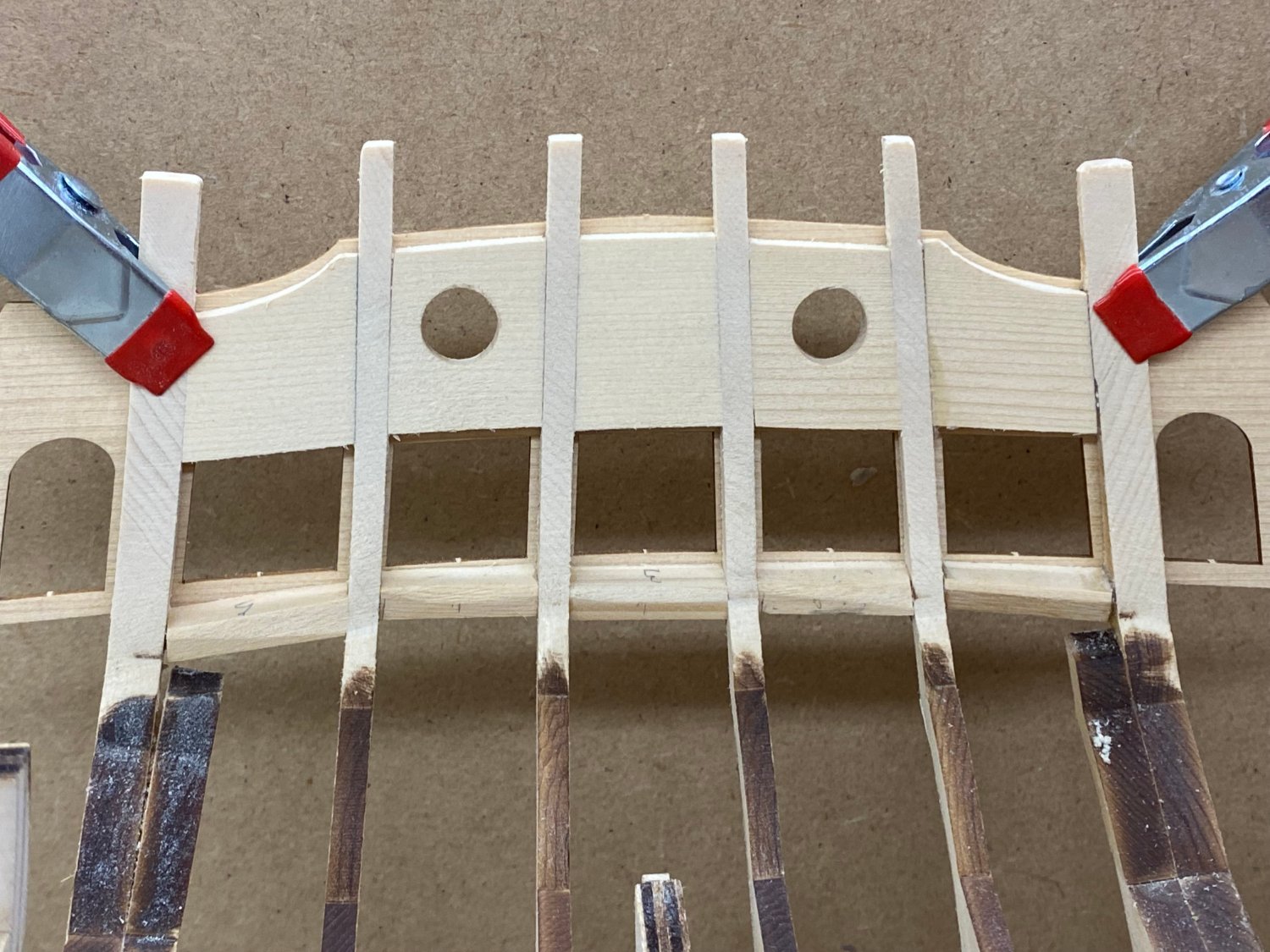
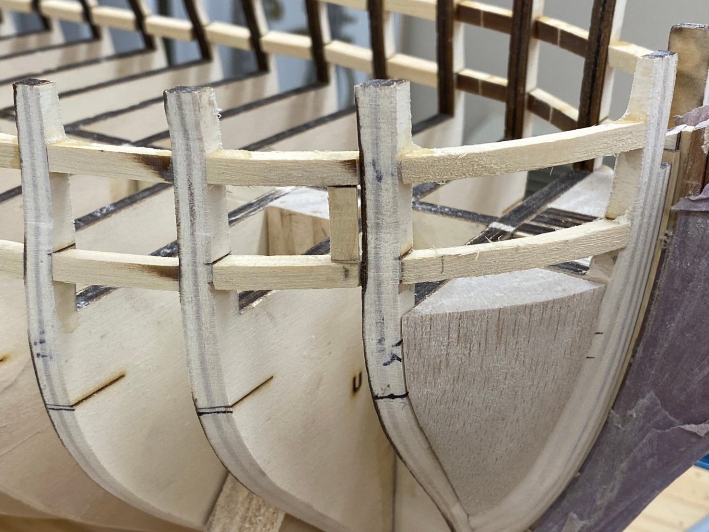
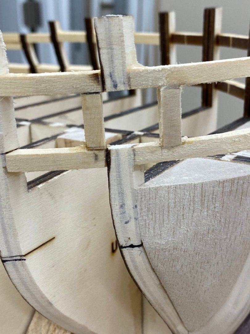
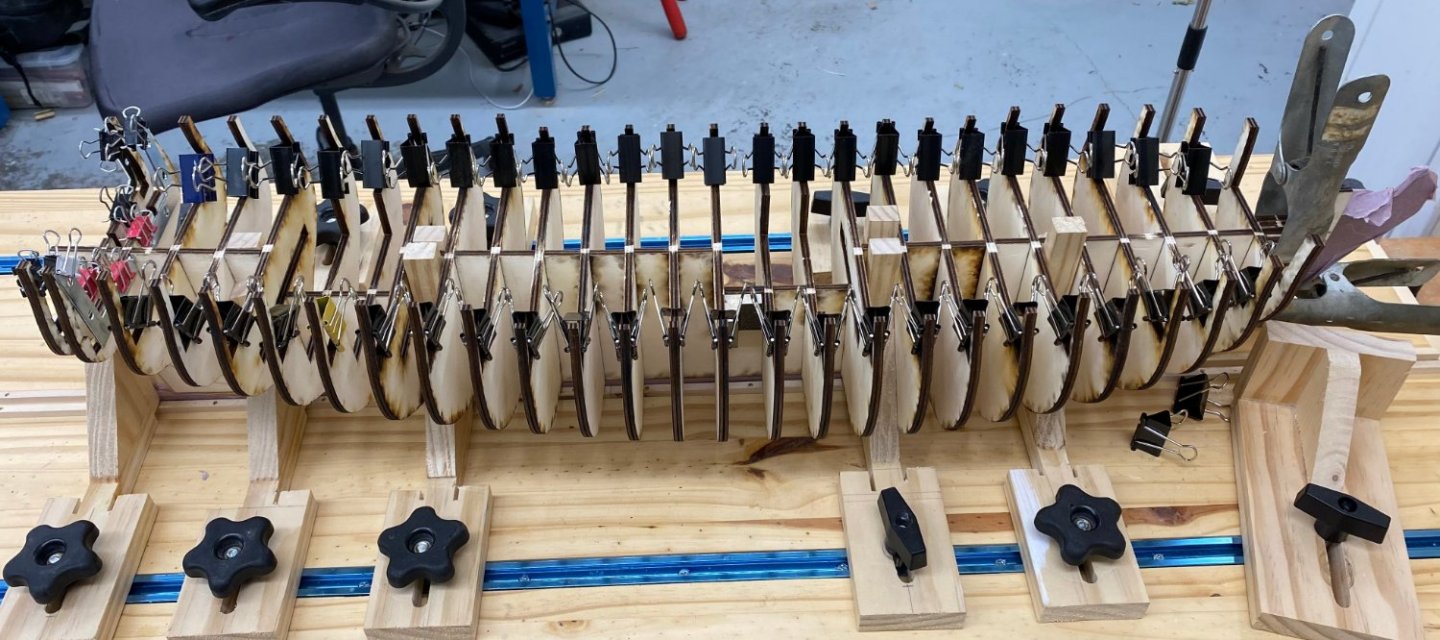
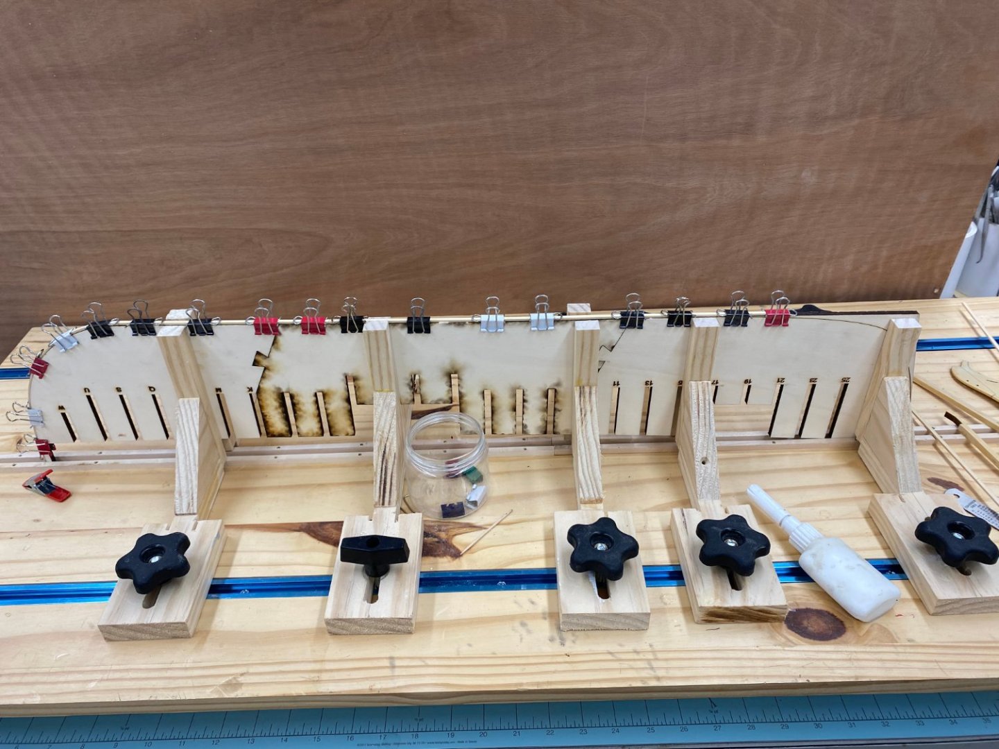
 So I decided to glue the sill and spacer between the A timbers before proceeding to the B and C/D timbers. I also used the disk sander to thin down the spacer to reduce the amount of sanding when all the stern timbers are installed. Here are the B timbers glued in place using the previously explained template.

- 389 replies
-
- 4
-

-
- winchelsea
- Syren Ship Model Company
- (and 1 more)
-
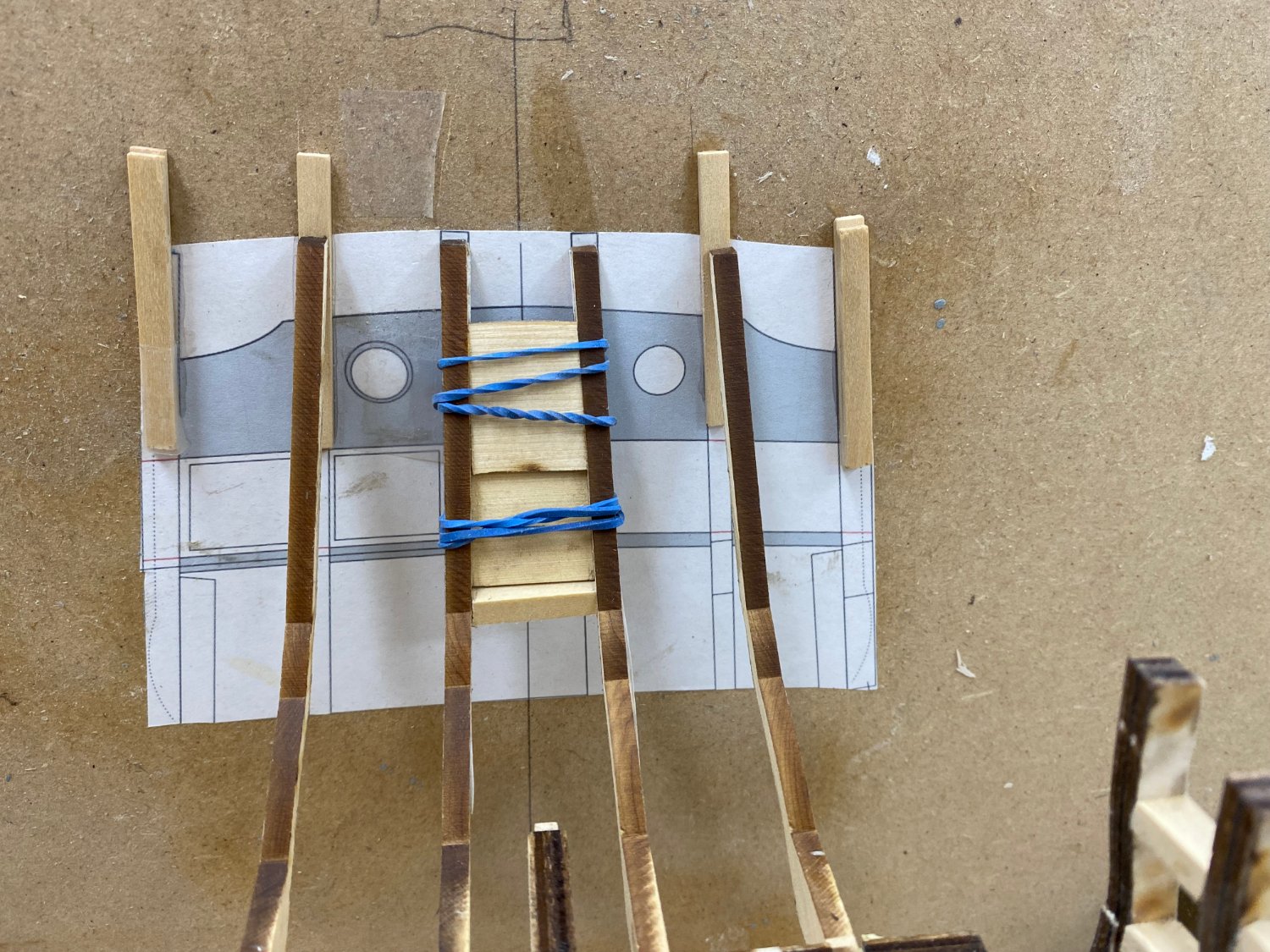
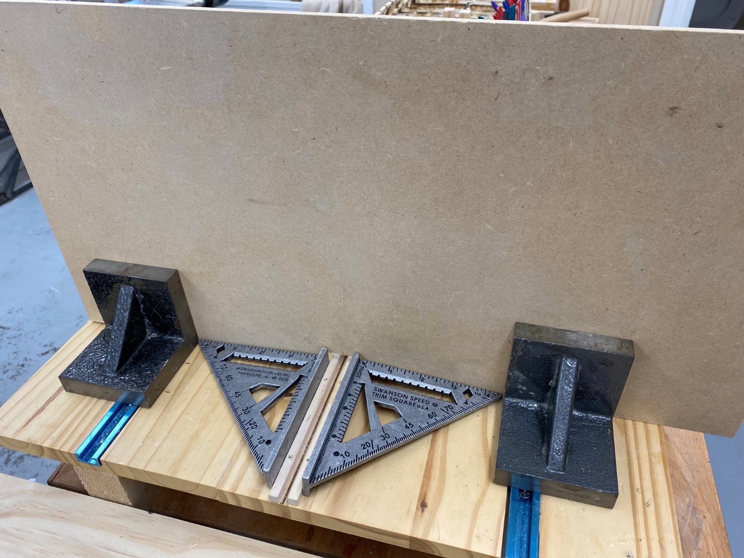
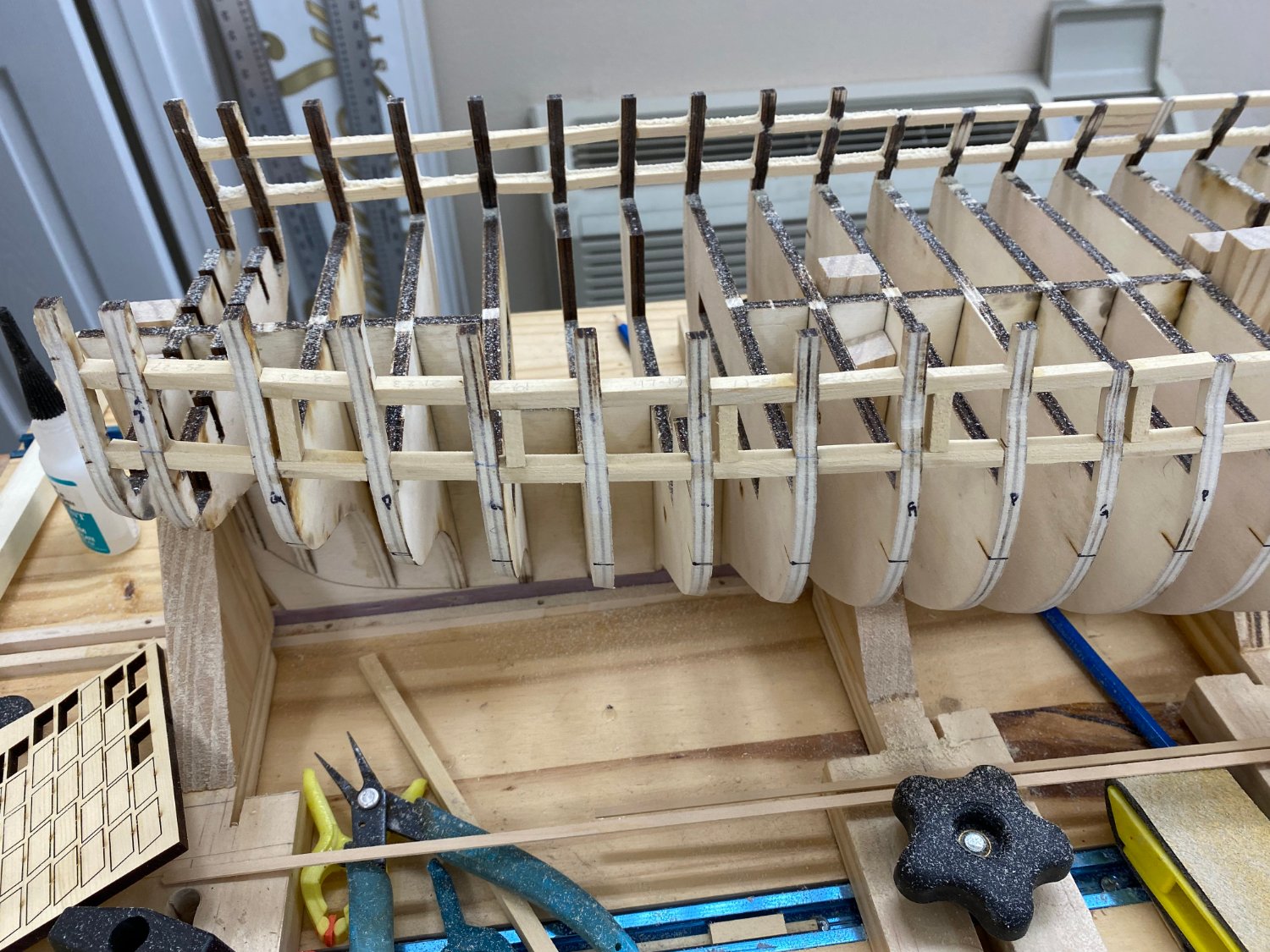
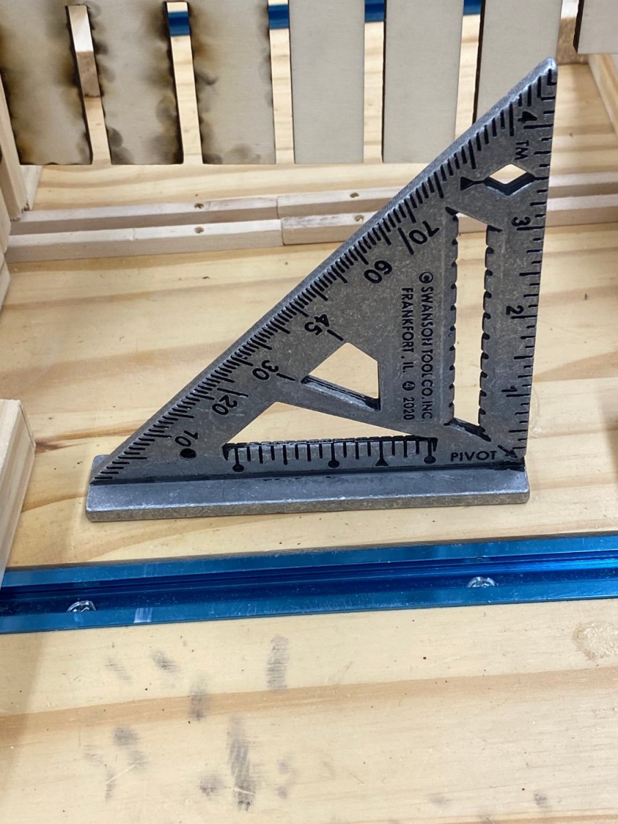
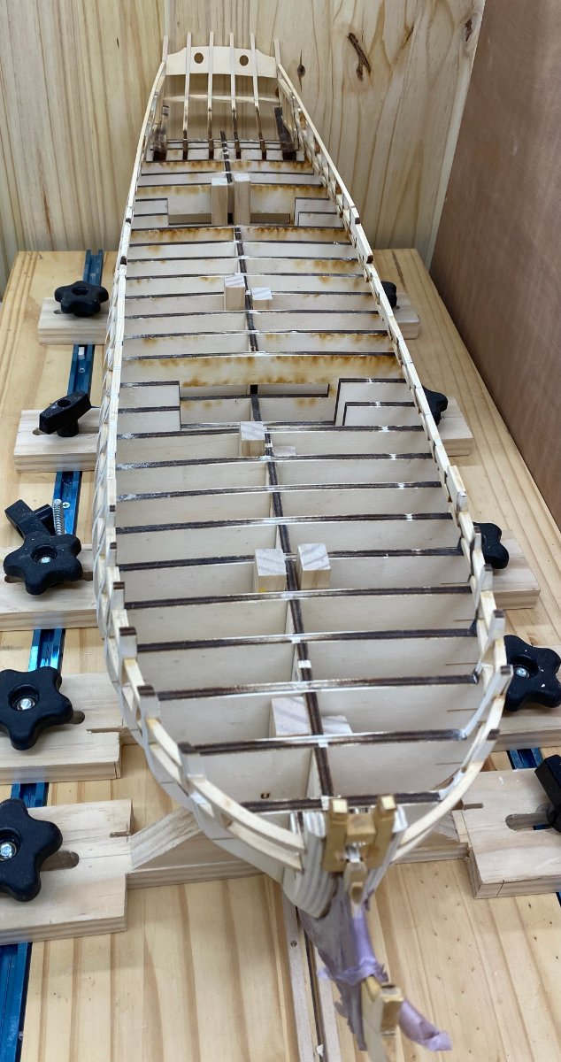
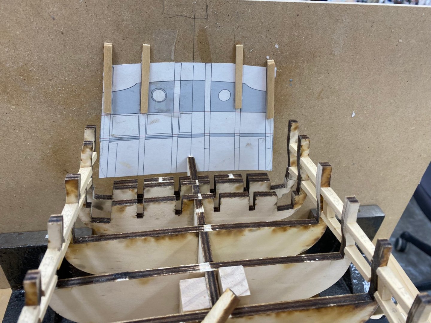
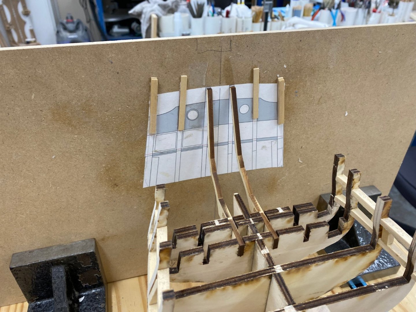
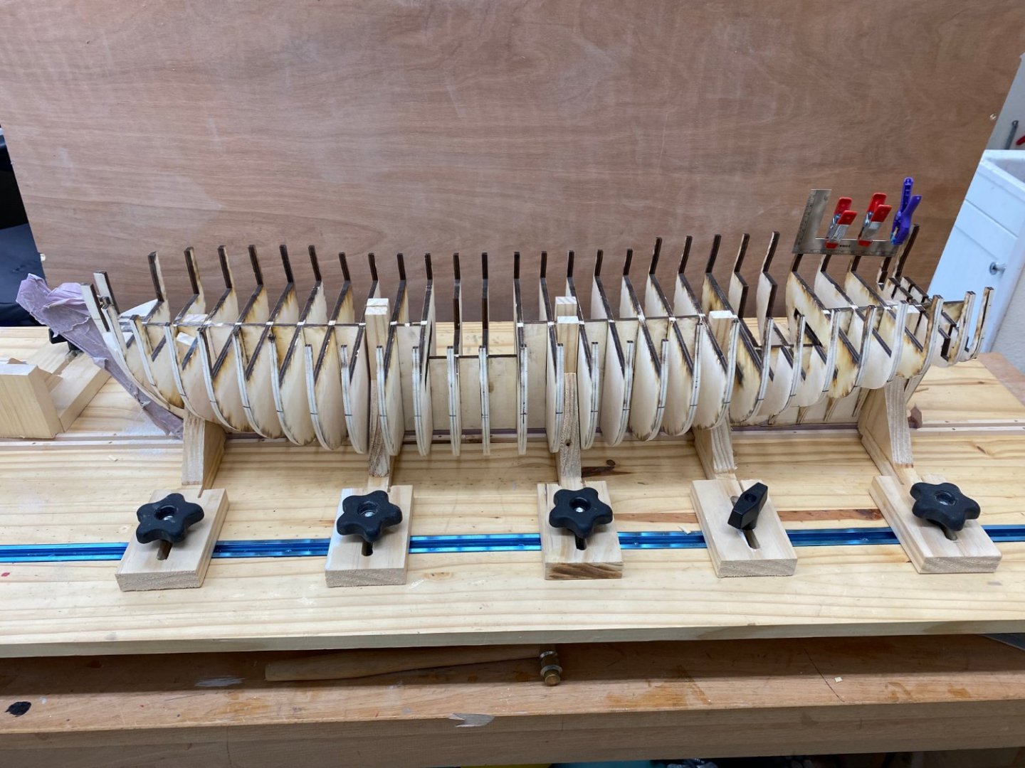
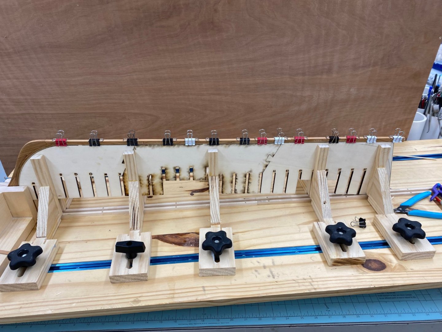
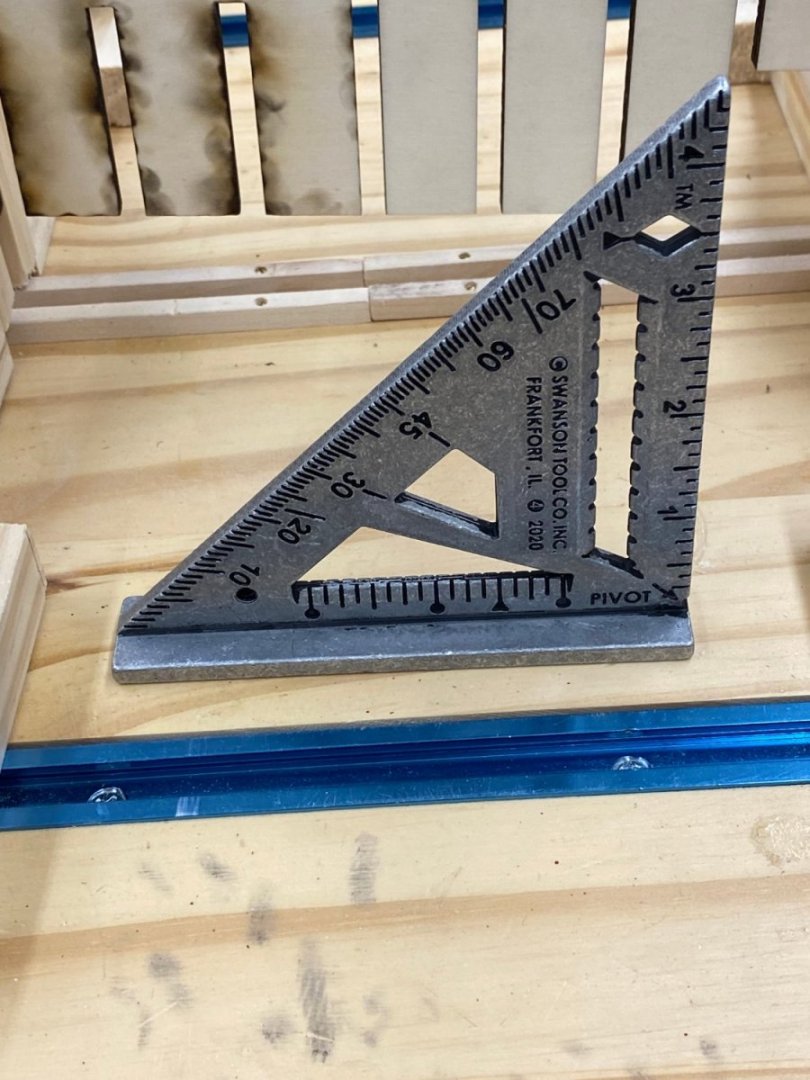
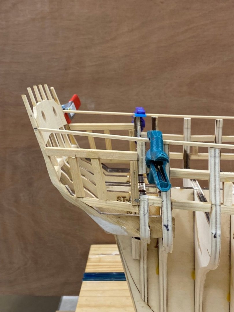
The port side gun ports are complete and have been faired to the hull. So now it is time for everyone's favorite part - STERN TIMBERS. I hopes of not repeating previous errors I added the stern timber template to a sheet of MDF. To that template I added spacers for the two sets of timbers (B and C/D) that are forward of the A timbers. By my measurements the total "offset" is 5/32" (from sheet 4 of the plans extending the centerline at the stern to the end of the transom at the hull) so the B timbers are 5/64" forward of the As and the C/D are 5/23 (aka 10/64")" forward. Here is the template in pla ce with the centyerline on the center keel. Now, of course the stern timbers are going to push this back so I needed a way to support the template and keep is perpendicular to the keel so I used two squares and for machinist blocks. Here you see two of the blocks and the two squares keeping the template perpendicular to the keel slot. The other two machinist blocks are on the other side holding the template vertical. So here we are with the A timbers in their slots and with the template just touching the ends of the timbers. They line up pretty well but the "real" alignment comes with the provided template captured between the two timbers. Now for the thin CA to lock the A timbers in place before something moves - just kidding, I will get my trusty Titebond out and use that to glue the A timbers in place. Hopefully without upsetting my "set-up". I have not decided yet whether to get the A timbers and the sill and spacer glued in before moving on to the B timbers. Seems like a good idea to get these "steady" and then deal with the other sets, one set at a time. But...

- 389 replies
-
- 5
-
-
- winchelsea
- Syren Ship Model Company
- (and 1 more)
-
Thanks Joe - when I built the 1/35 scale Endeavour I filled the entire hull with balsa - I should have invested in a better dust collection system - I am still finding pockets of balsa dust.
- 389 replies
-
- 2
-
-
- winchelsea
- Syren Ship Model Company
- (and 1 more)
-
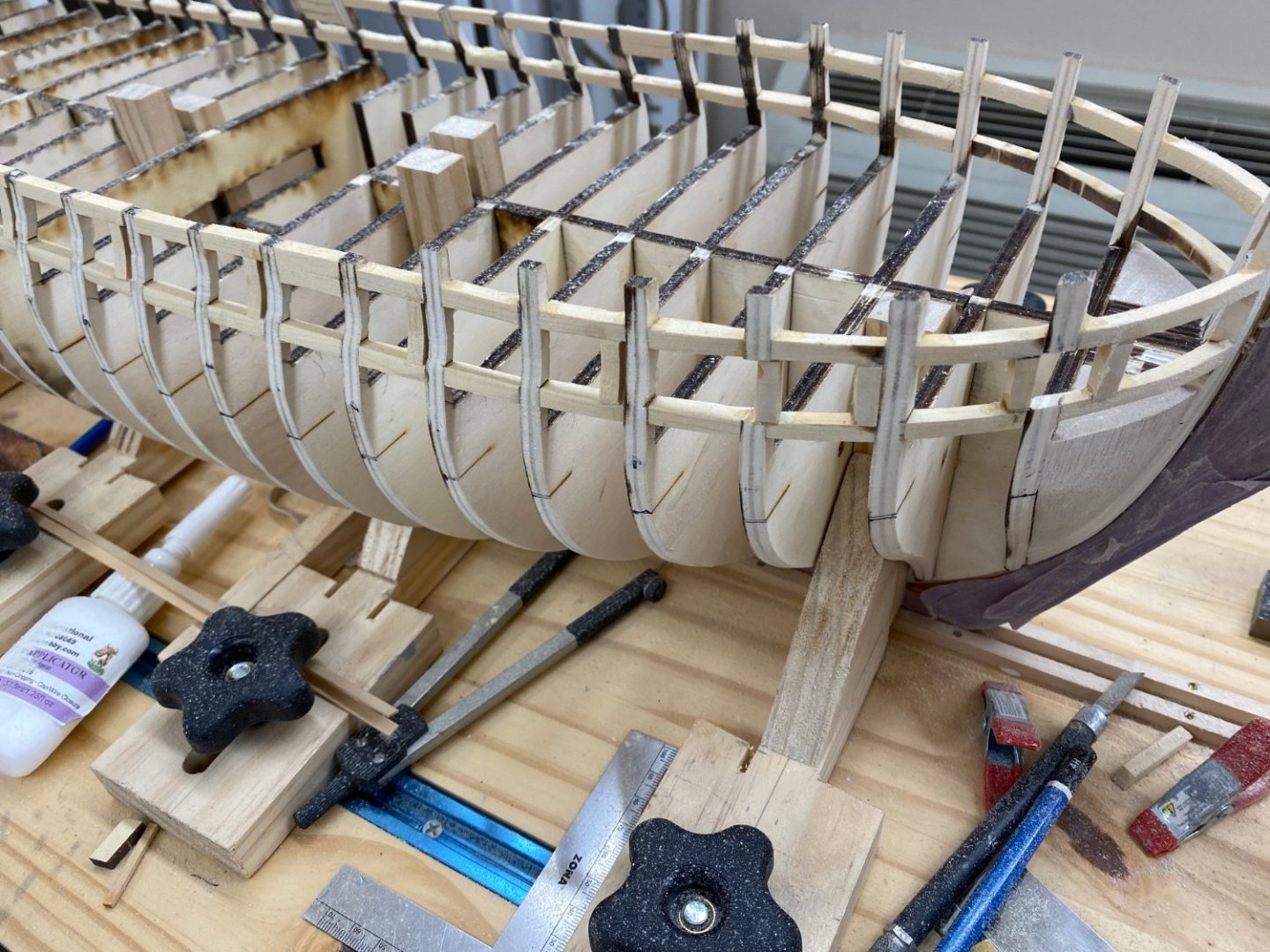
Welcome aboard Joe. Starboard side gun ports complete and faired into the hull. Fairing in the port side now and will get the ports completed tomorrow baring some "unfortunate incident" (like a bulkhead extension breaking). Here is the starboard side.


- 389 replies
-
- 6
-
-
- winchelsea
- Syren Ship Model Company
- (and 1 more)
-
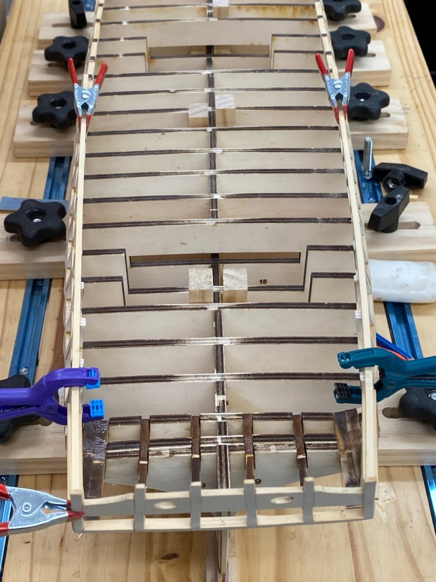
I got all the upper sills completed. As with my previous attempt I added an upper sill at all the bulkhead extensions instead of just where they are shown in the plans. I think it reduces the place where something could "catch" on the hull, like a shirt sleeve or errant tool. Anyway, I decided to depart somewhat from the order of items in the instructions. Since I know from the previous build that the forward bulwarks are going to have to be thinned for the bollard timber installation, I decided to do that now after fairing the upper and lower sills on the outer hull. I think it will be easier to do this before the gun port installations are completed, especially since two of the bulkhead extensions at the bow are going to be cut out for the gun port sides to be installed. So after thinning the interior bulwarks forward I started installing the gun port sides from the bow since that is where two of the three bulkhead extensions have to be cut out. Here is the first side installed: And now with both. The eagle eyed will not the balsa wood filler blocks installed to fair the bulkhead W to the bow fillers. I have used this technique in the past and thought it might prove useful here as well.

- 389 replies
-
- 7
-
-
- winchelsea
- Syren Ship Model Company
- (and 1 more)
-
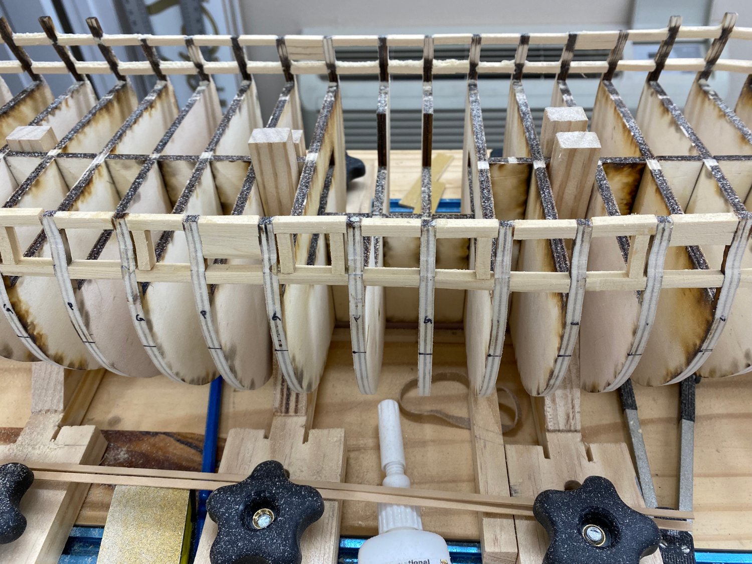
Lower sills are complete - and I think it looks smoother than my first attempt but I am too chicken to actually go back and look at the photos - don't want to face a possible "inconvenient truth". Anyway here is what it looks like. Rubber bands are holding the bulkheads so the sills (which are sized by the distance at the center keel per the instructions) will get a good grip on the bulkheads extensions.
- 389 replies
-
- 7
-
-
- winchelsea
- Syren Ship Model Company
- (and 1 more)
-
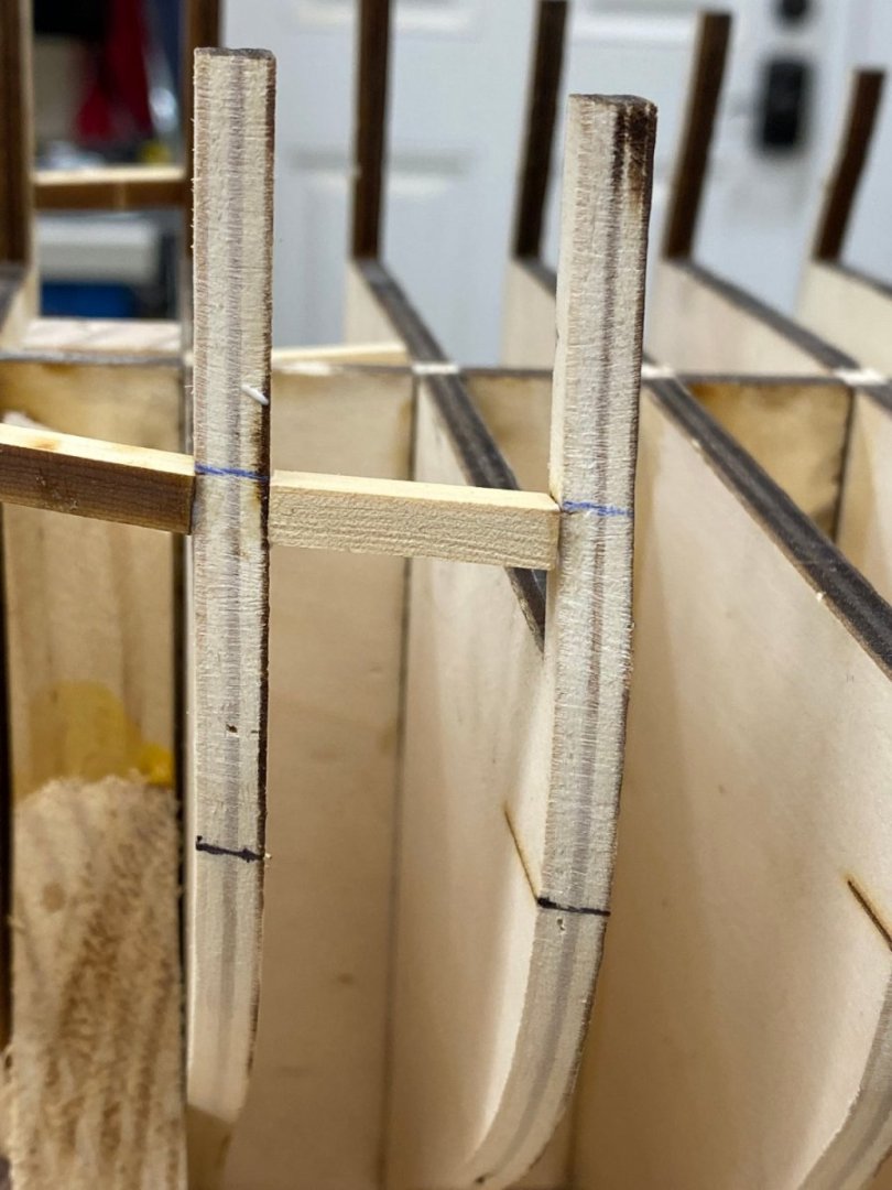
If I remember correctly the last time I did the sill framing I did one side and then the other. Probably not the smartest move I ever made but... So this time I moved the hull over to a place where I can get to both sides without moving the build board and will do one sill on the port side, then the corresponding one on the starboard side. Hopefully this will keep both sides consistent, even if incorrect at least consistent. So with the sheer line marked on both sides I installed the three laser cut sills on each side without having to do much modification to the provided pieces. The next four or five sills need the ends beveled since the frames are still moving out to the maximum beam. To make these I cut some pieces of the 3/16" X 1/4" to just more than the measured distance between frames and then laid them across the frames next to the bulkhead extensions and marked the ends to get handle on the angle of the bevel. I used the disk sander with 320 grit paper to sand the sill to the marked bevel then checked the fit next to the center keel. A few more trips to the disk sander and both pieces fit. Now it is a relatively simple matter to move the pieces to the end of the frames and glue them in place. I have noticed that while the sills fit "snugly" at the center keel at the outboard edge the can be a bit short - at least the ones I have done so far. Nothing large but enough that I have to use a rubber band to keep the sills between the frames. I guess as long as the frame ends are the same distance apart as at the center keel everything should work out "okay". At least that is my hope.

- 389 replies
-
- 5
-
-
- winchelsea
- Syren Ship Model Company
- (and 1 more)
-
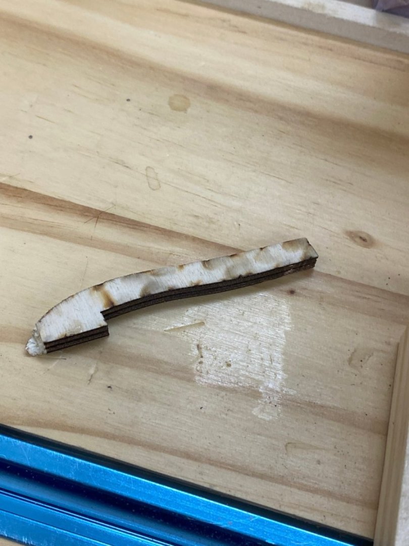
Hull fairing is completed and the line for the lower sills established. That's the good news - the bad news is that I broke off two of the bulkhead extensions this time. And wouldn't you know it they are both at the stern, one on bulkhead 28 and one on bulkhead 27 but luckily not on the same side. Here is the bulkhead 27 break which is the worst one. The bulkhead 28 break was further up the extension. And here is the errant piece. As you can see not much area to get a good glue joint. But since this bulkhead includes one of the notches for the stern timbers I can't use more wood to strengthen the joint without impacting the stern timbers. So I clamped a small ruler to the extensions on bulkheads 25 and 23 and clamped the piece for bulkhead 27 to the ruler, applied some white glue and hope for the best. At least this in not the one that I have to cut a piece out of later - that isa the broken one on the other side. Here is the bulkhead 28 repair. And here is the hull waiting to begin the lower sill installations once the bulkhead 27 repair has dried.


- 389 replies
-
- 7
-
-
- winchelsea
- Syren Ship Model Company
- (and 1 more)
-
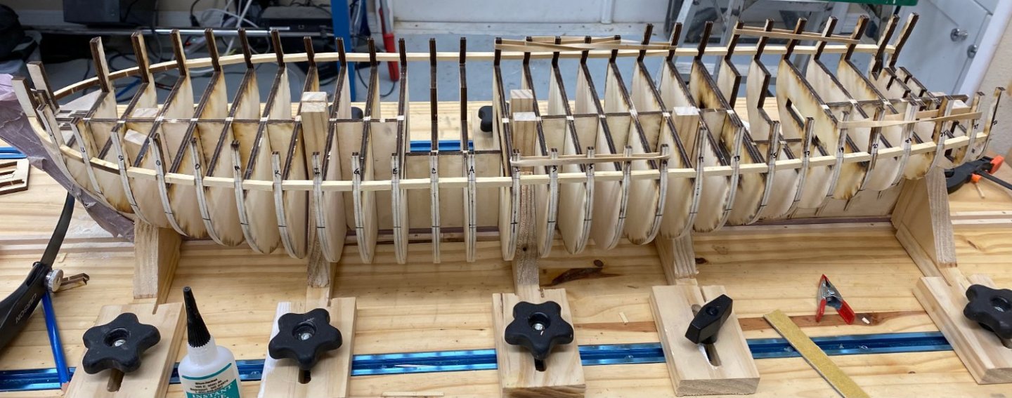
Bulkhead installation completed. Clamps are holding the bow fillers in place. Binder clips are to protect the bulkhead extensions when the hull fairing begins in earnest tomorrow.
- 389 replies
-
- 5
-
-
- winchelsea
- Syren Ship Model Company
- (and 1 more)
-
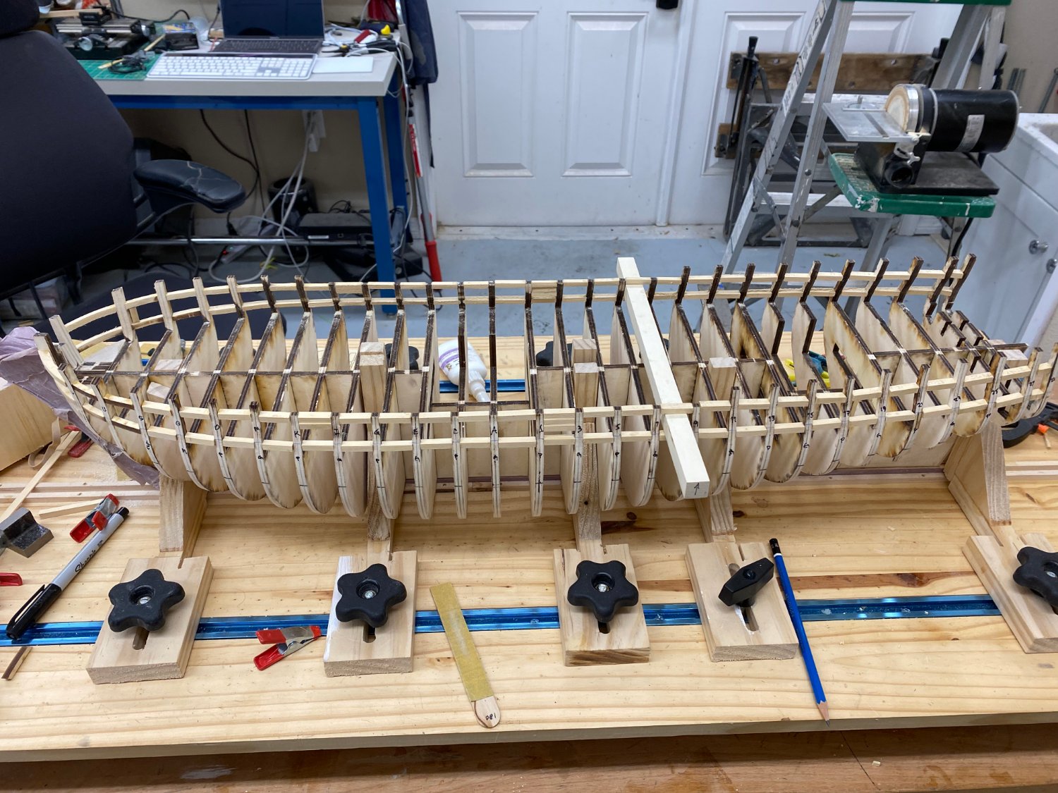
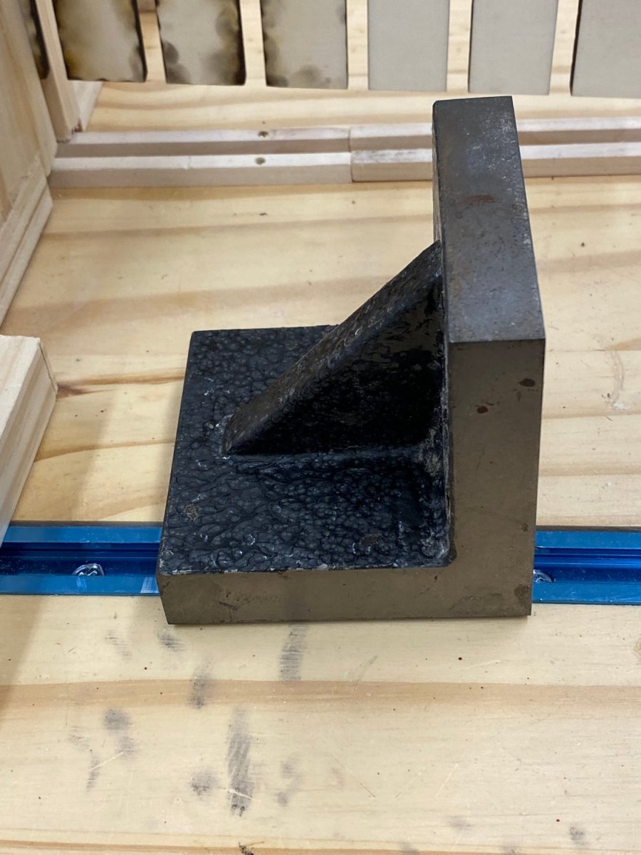
After drying overnight I added the rest of the keel and false keel parts. No surprises as expected. I did buy some 4 1/2" trim squares to assist in adding the bulkheads. Previously I used machinist angle blocks. In trying to figure out how I managed to get the aft two bulkheads so far out of alignment I decided to change "strategy" this time. Before I started at the center of the keel and worked toward each end. This means that unless you are using a squaring piece that is quite short - short enough to fit between the bulkheads - that you are clamping the squaring frame (what ever type you are using) on the forward side of the bulkheads going forward and aft of the ones going aft. As you near the bow and stern there is less and less of the center bulkhead to clamp to and thus the likelihood of error increases just where errors will be the most obvious (and difficult to fix). So my plan is to start at the stern with bulkheads 28, 27, 25, 23 and 21; get them straight and true; then work the bow bulkheads W, U, S, Q and O and do the same. Then proceed with one bulkhead aft, then one forward. This means that as I get to midships I will run out of room between the bulkheads and have to resort to "other means" to get the bulkheads square and true but I believe that an error in this area (especially with the narrow bulkhead spacing) would be easier to correct than at the bow or stern. I will start adding the bulkheads when the glue on the false keel has set and I have covered the stem and keel with masking tape to protect them from what is to come.

- 389 replies
-
- 5
-
-
- winchelsea
- Syren Ship Model Company
- (and 1 more)
-
It took a good bit of sanding but I eventually got the cherry stem to fit the center keel and got it glued on. I will let this set overnight and put the rest of the keel on tomorrow.
- 389 replies
-
- 4
-
-
- winchelsea
- Syren Ship Model Company
- (and 1 more)
-
Here we are again - I glued the center keel together on the granite top of the kitchen island (with parchment paper to protect the granite) and two quartz cutting boards on top. I am pretty sure it is a straight as I can make it. I put in in the build board and added the rabbit strip. Next the bearding line and then the stem. Time to decide which stem/keel to use. I am leaning toward the cherry stem/keel at this point to get so contrast with the cedar hull planking.
- 389 replies
-
- 4
-
-
- winchelsea
- Syren Ship Model Company
- (and 1 more)
-
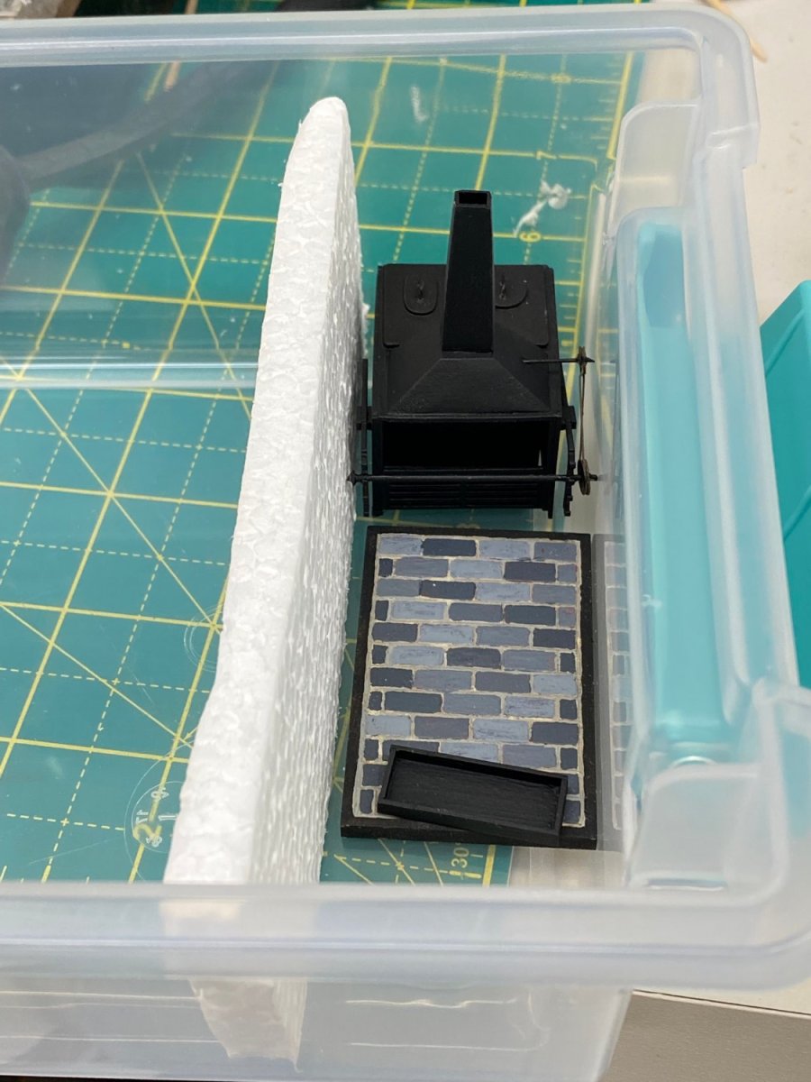
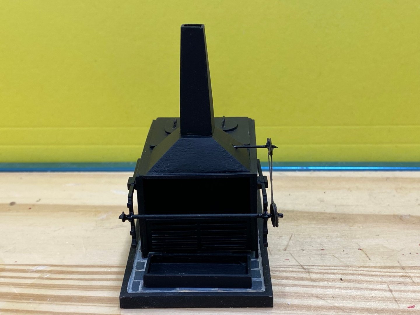
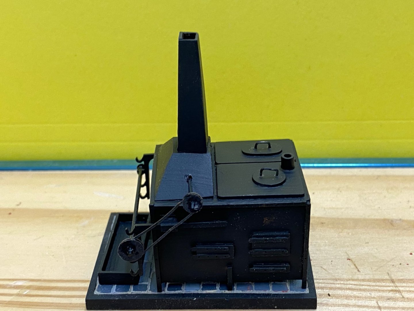
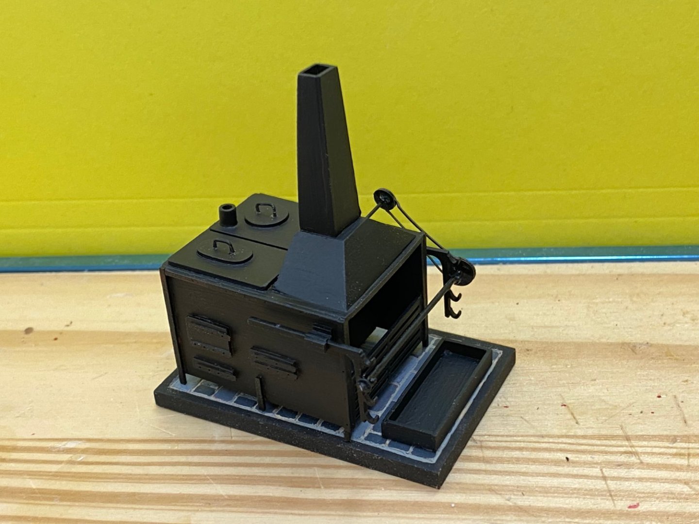
I got the stove finished - just in the nick of time as the plywood pieces arrived today - Thanks Chuck for the expedited service. So here is my version of the stove. I did not get the paint as smooth as I probably should have and being a rookie at the weathering powder business I did not get the "real metal" but based on my experience with building Confederacy, the stove is not in a highly visible location. I looked ahead to where the stove is installed and noted that the platform the stove sits on was completely black. Probably more accurate but since the provided platform had the outline of bricks (I assume bricks) I decided to "get fancy" and deepened the brick lines and painted the base to look more like bricks - gray bricks rather than red. Not that you can really see them but... So here is the stove: Now I have to pack it away somewhere out of the "line of fire" so it will still be okay when install time - probably sometime in 2024. I also added the capstan and some of the pieces (stern lamp kits, chain plates, etc.) that will be needed "later". So now back to the "plywood pieces"!


- 389 replies
-
- 8
-
-
- winchelsea
- Syren Ship Model Company
- (and 1 more)
-
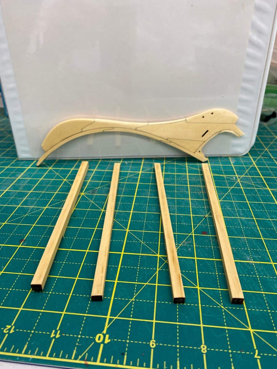
Since I have the Chapter one package (in both cedar and cherry) I decided to get started on the parts that I can before the plywood pieces arrive. I fashioned both stems and keel pieces and have three coats of WoP on each. I have not decided which set to use this time. I used the Alaskan Yellow Cedar (AYC) on the first hull. I used a variety of wood types when I built Confederacy. The different types looked okay at the bow but the stern (hull/rudder) did not come out as well as I had hoped. Still plenty of time to think about what wood goes where. In the meantime I am working on the stove.
- 389 replies
-
- 5
-
-
- winchelsea
- Syren Ship Model Company
- (and 1 more)
-
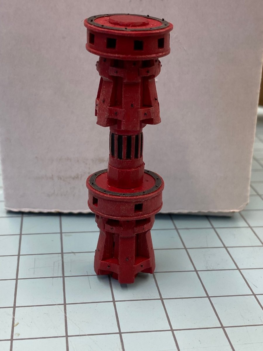
Thanks Chuck, While waiting for the new plywood pieces to arrive I assembled and painted the dual capstan from Chuck's kit. No real surprises except I would (contrary to the instructions) sand off the char on the entire center section, not just the parts that show between the whelps. The three pieces that make up the center section of each capstan are laser cut 1/4" thick pieces which, when stacked one atop the others exhibit a good deal of the laser offset that is part of the laser cutting process. I followed the instructions on the lower capstan but sanded the entire center section on the upper- carefully mind you, you have to preserve the hexagonal shape but getting a solid surface from top to bottom on each side is important also. Anyway, here is what it looks like (two sections are not glued together, upper is just sitting on the lower) before I put it away for "later".

- 389 replies
-
- 8
-
-

-
- winchelsea
- Syren Ship Model Company
- (and 1 more)
-
Chuck/Glenn, Appreciate the advise but the problem is not exclusively with the stern timbers. Clearly that is part of it but I have lost track of "ground truth" so to speak and am not sure if I adjust the stern frame/sill/fillers it is going to solve the problem. I remember now having to narrow the C/D stern timbers on the starboard side where they fit into the bulkhead assembly when I initially dry fit them. That was (I assume now) because that side is canted in slightly making the slots narrower. I should have looked more closely at the time but... I think I am more comfortable staring over and hopefully Chuck will have the new materials on the way shortly. My girlfriend wants bedroom #2 painted so this will give me the time to do that and avoid "model building distractions" while slinging paint and drywall paste.
- 389 replies
-
- 2
-
-
- winchelsea
- Syren Ship Model Company
- (and 1 more)
-
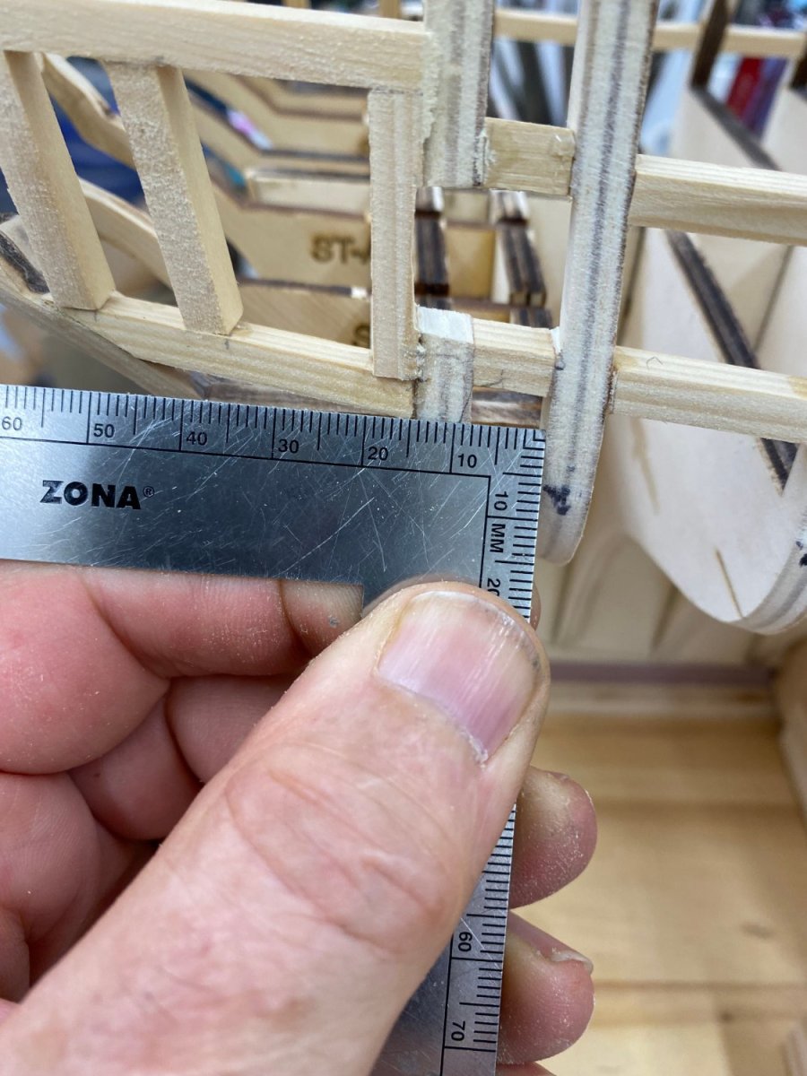
I have made a series of measurements at the stern of the hull and have come to the conclusion that one side is approximately 3mm longer than the other. The error that I apparently introduced while adding the port sills was exacerbated by my misalignment of the stern timbers. I have concluded that this is unrecoverable and have decided to restart my Winchelsea construction. I ordered a new set of hull formers and bulkheads last night. It will be a week or so before I can restart.
- 389 replies
-
- 2
-
-
- winchelsea
- Syren Ship Model Company
- (and 1 more)
-
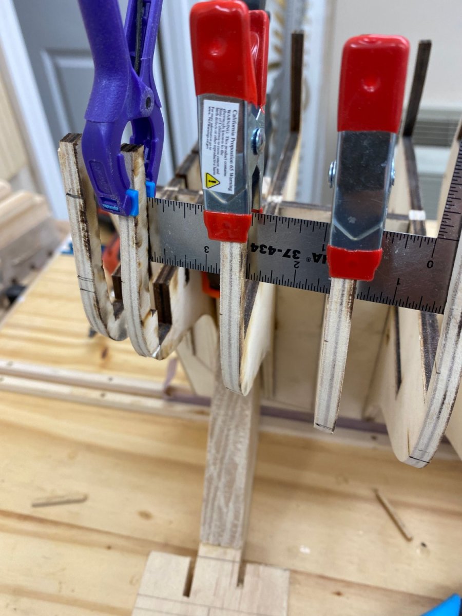
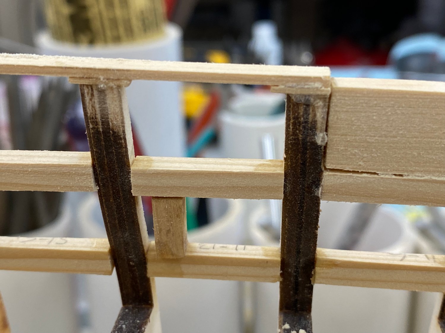
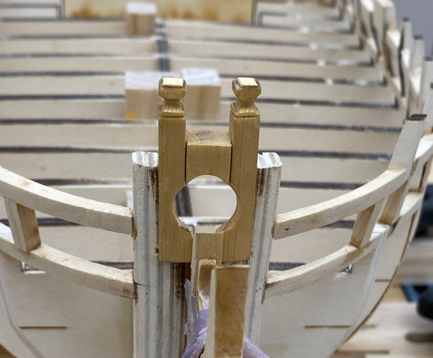
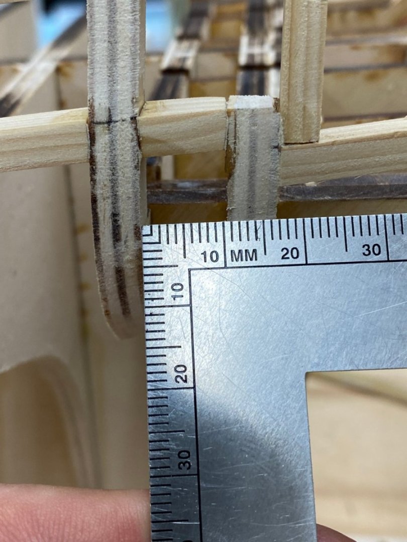
So I installed the bollard timbers that I have been working on while waiting for glue to dry on the hull and faired in the hance pieces and quarter gallery timbers. I believe that completes chapter one 😀 However, I have come across two items to work on my worry beads as we move forward. First, the distance between bulkheads 27 and 28 is not the same on both sides. It is approx 10mm on the port side and about 8.5mm on the starboard side. Ii would seem that the port side has moved aft somehow as the drawing shows the gap to be 8.5mm. I fear this is going to cause all kinds of issues with the quarter galleries, at least on one side. I do not know what, if anything I can do at this point except assume there will be problems on the port side. The other problem occurred when I installed the aft hance pieces. On the starboard side the top of the hance piece fit directly under the piece running across the tops of the bulkhead extensions. however, on the port side the hance piece stuck up above the railing. I added 1/32" shims under the railing on the first two bulkhead extensions to keep the hance piece at the correct level with respect to the railing. Speaking of the bollard timbers - You will note that the additional piece that is added on top to form the upper "layer" appears to be quite "bright" compared to the material below it. I believe that the difference in the wood grain is causing this issue (an issue for me anyway). The bollard timber "blanks" in the carrier sheet are all oriented with the grain running from top to bottom (or the other way round). So when sanding the top of the timber (to get the laser char off for instance) you are sanding across the end grain. The end grain is almost always going to look darker than cross grain. The piece added to the top cross grain and thus lighter. The rest of the hull at the end of Chapter One.


- 389 replies
-
- 4
-
-
- winchelsea
- Syren Ship Model Company
- (and 1 more)
-
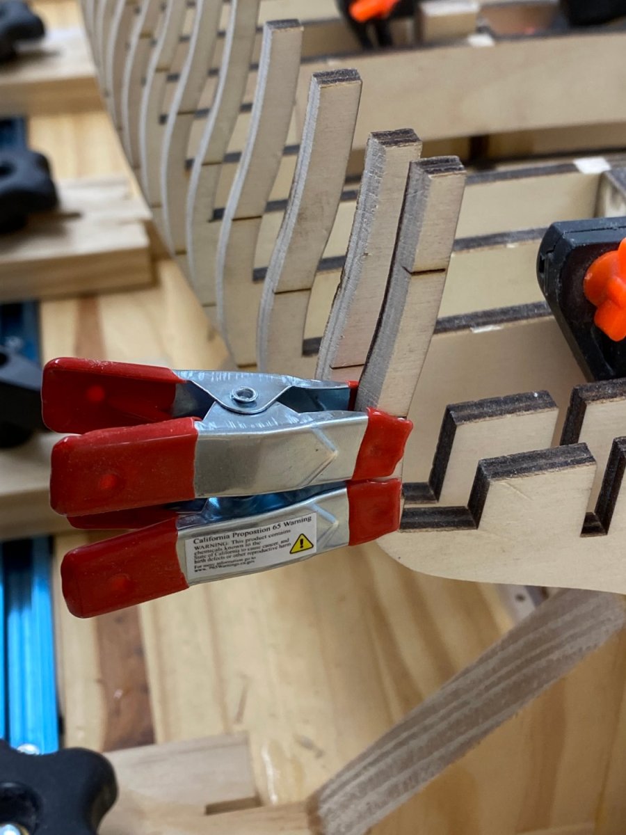
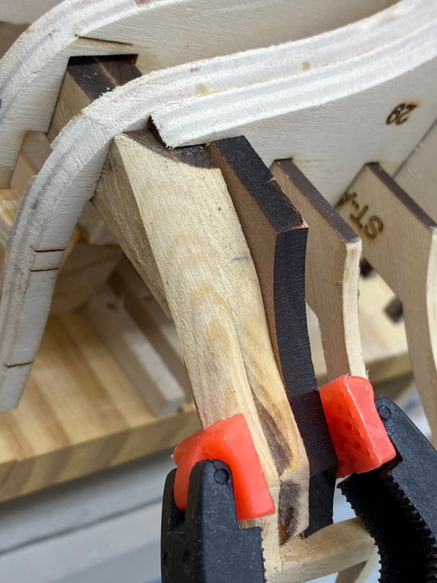
With the fairing done and the over done repaired it is on to the Quarter galley framing. As the instructions say - "should be a piece of cake". One lesson learned (or maybe relearned) is the use the maximum tpi saw you have to cut the bulkhead extensions. I tried the "quick" way and had the glue joints (which are what is holding things together once the bulkhead extension is cut) come apart. So much for a piece of cake. Anyway, I got that repaired and got the framing in place without too much more drama but I did very carefully measure (and remeasure) where the horizontal framing timbers are sup[posed to be. The 1/16 X 1/8 piece across the tops of the bulkhead extensions I glued to the transom and the first two bulkhead extensions - as you can see below. I am going to let them dry before I glue it to the rest of the bulkhead extensions as it needs to curve more than I am will to try and do in one pass. While this has been going on I have been fabbing the bollard timbers and they are almost ready for installation. Time to get the hance pieces from the sheet carrier I guess.


- 389 replies
-
- 5
-
-
- winchelsea
- Syren Ship Model Company
- (and 1 more)
-
After some wood filler and a bit of sanding I think I am ready to call this DONE! On to the QGalley framing.
- 389 replies
-
- 5
-
-
- winchelsea
- Syren Ship Model Company
- (and 1 more)
-
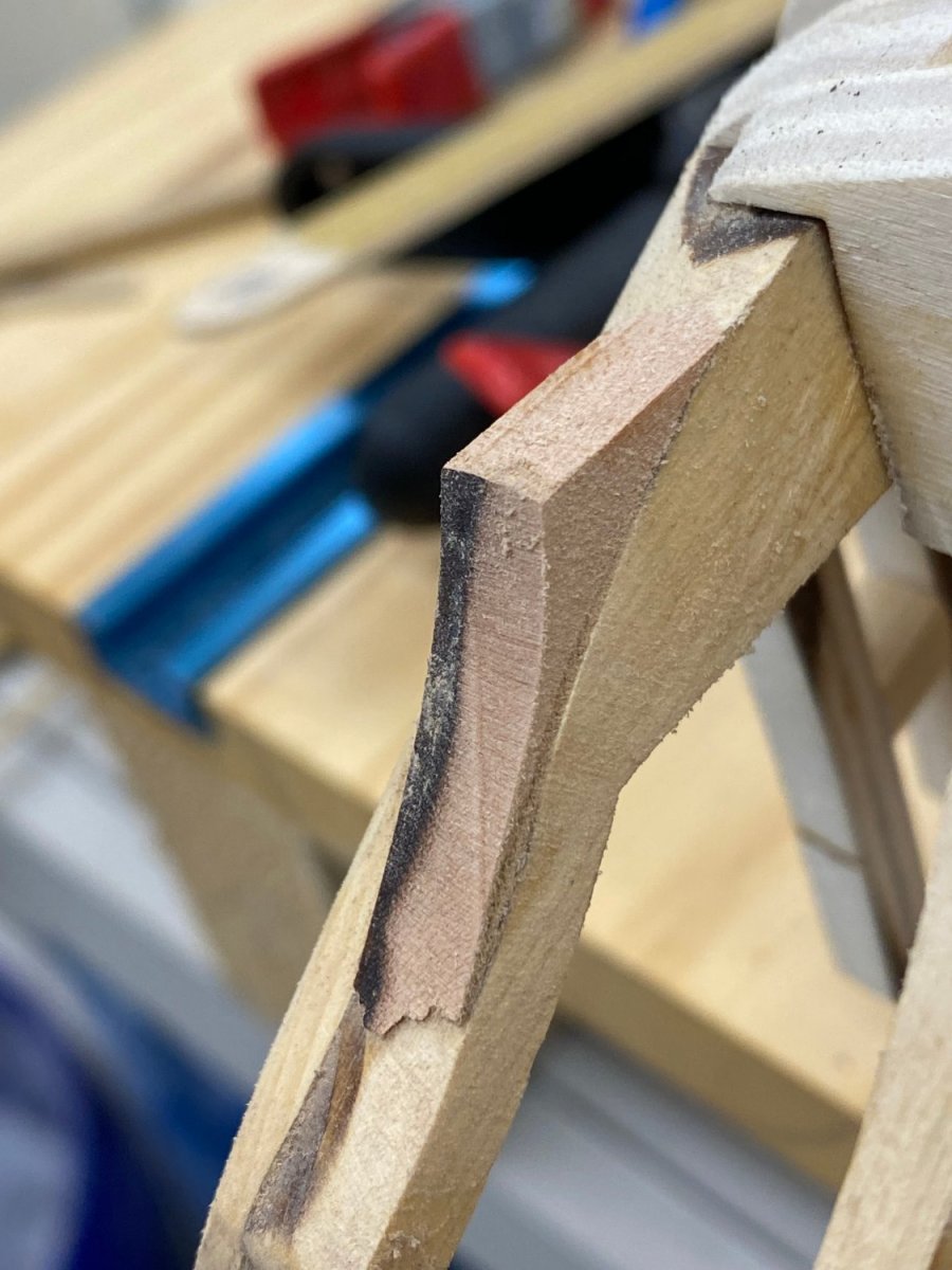
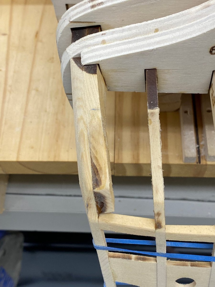
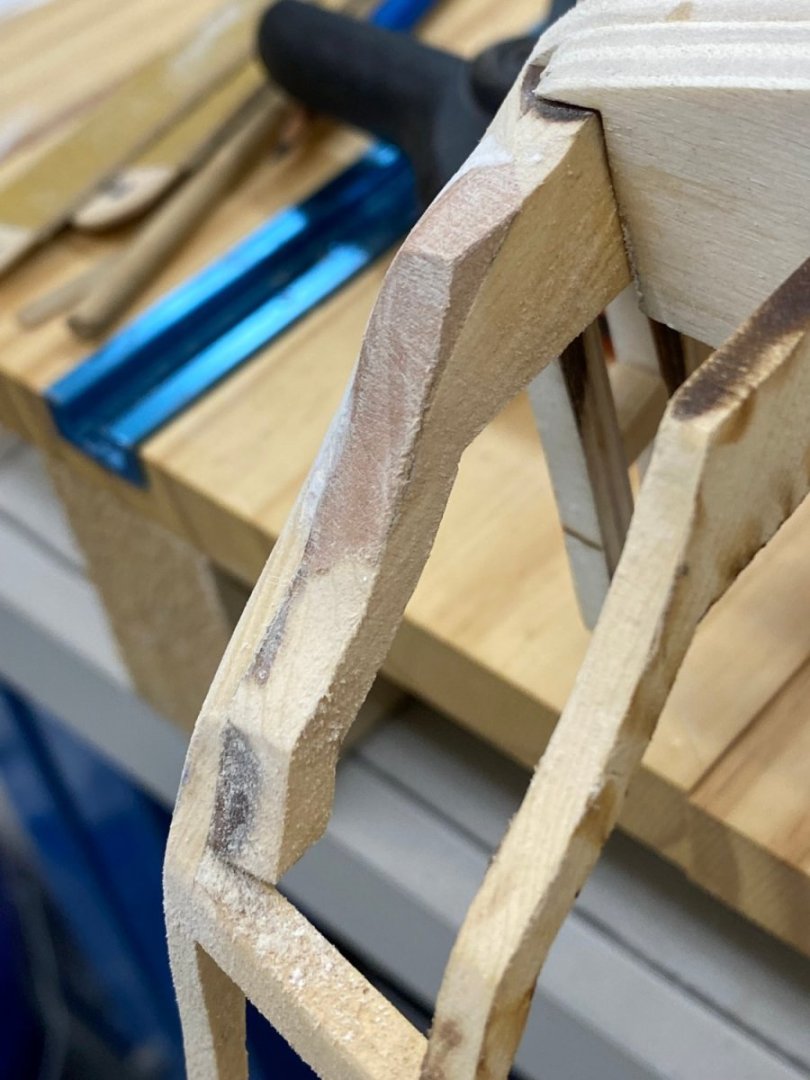
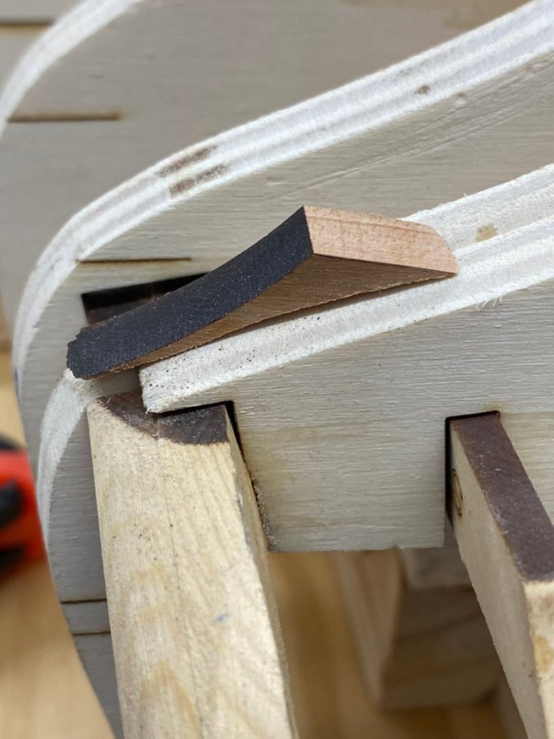
Back to the stern timber "rebuild". Here is the additional piece after the glue set. Because the existing timber had been "faired" the new piece is canted outboard. I check and the port side it also canted outboard but not this much so I need to try and get the "mating surface" of the timber to more closely match the port side. For the curved part I used a piece of 1/2" dowel with a 2" wide piece of 150 grit paper wrapped around near one end and ran the other end over the port side in a back and forth manner using the port side as a "template". The sandpaper only touched the other "C" timber so I did not distort the surfaces of the inner timbers (at least I don't think so). So here is where we are now. I got about 2/3 of the surface "flattened" if you believe the laser char that was removed. I think I will leave it here until I see how the transom planking starts. If more "adjustment" is needed I will address it then. I need to measure how far the "lip" is from bulkhead 29 on each side and adjust the starboard side if it extends aft too far (I think it is about 1/8" to far). After that adjustment I will add some wood filler to blend the outer edge into the "D" timber. Hopefully the port side is how the fairing is supposed to look. Otherwise 🥵


- 389 replies
-
- 3
-
-
- winchelsea
- Syren Ship Model Company
- (and 1 more)
-
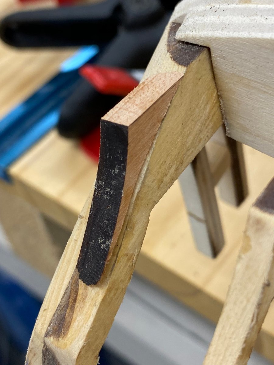
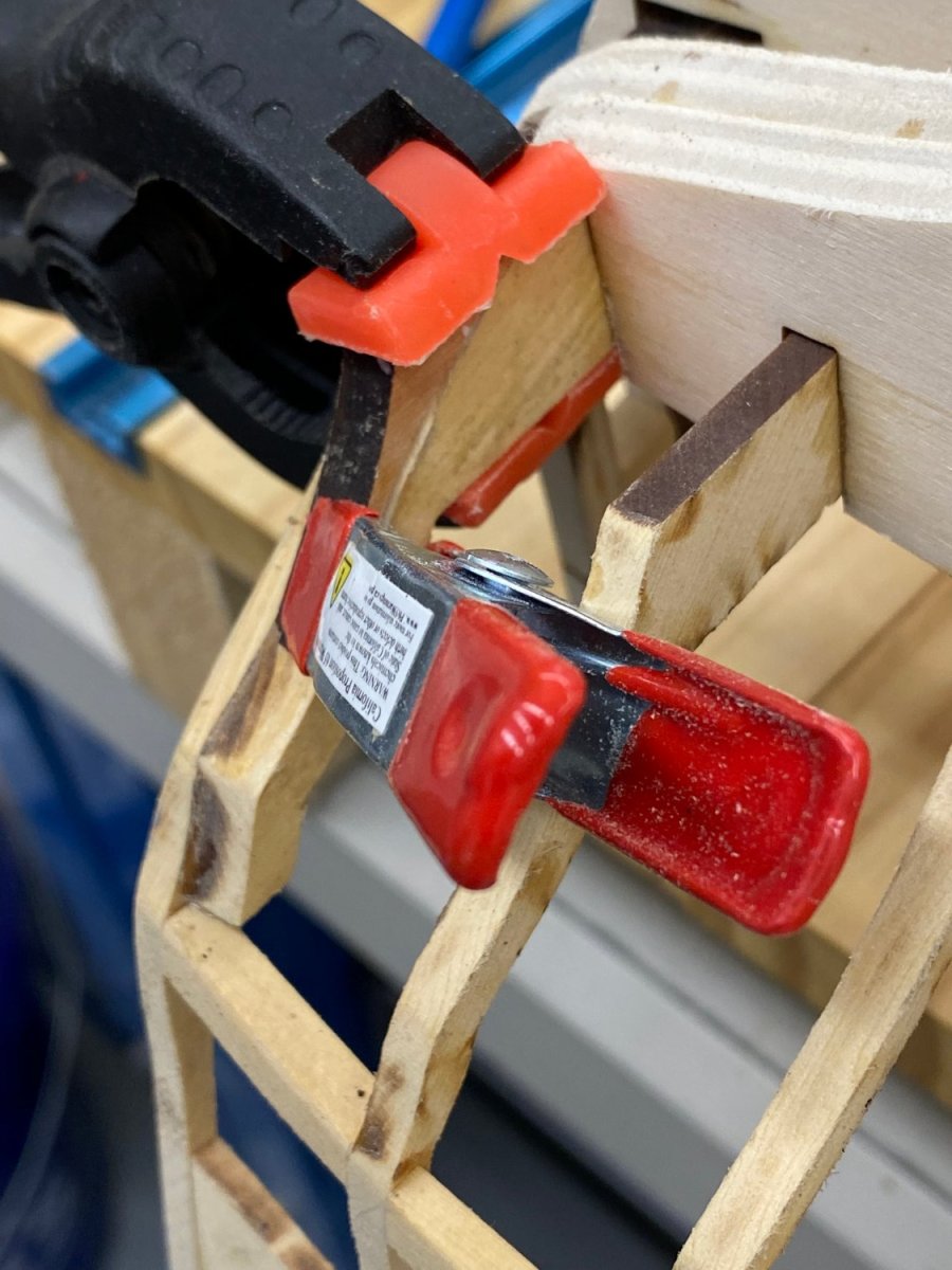
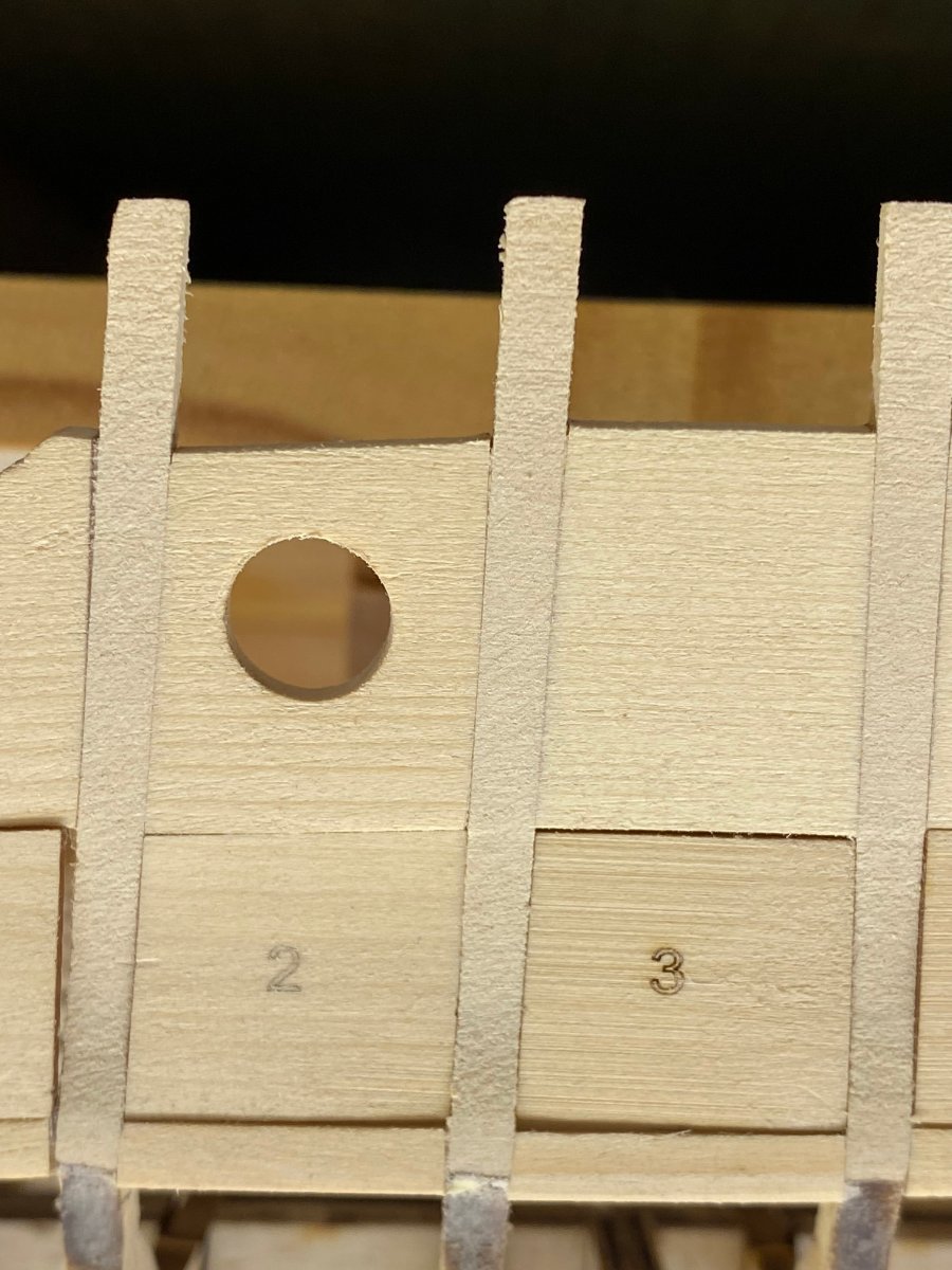
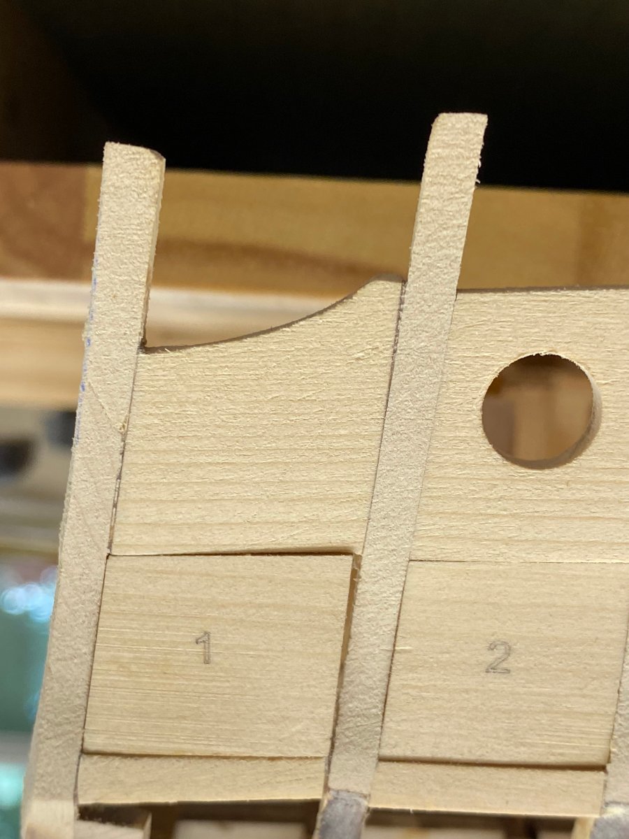
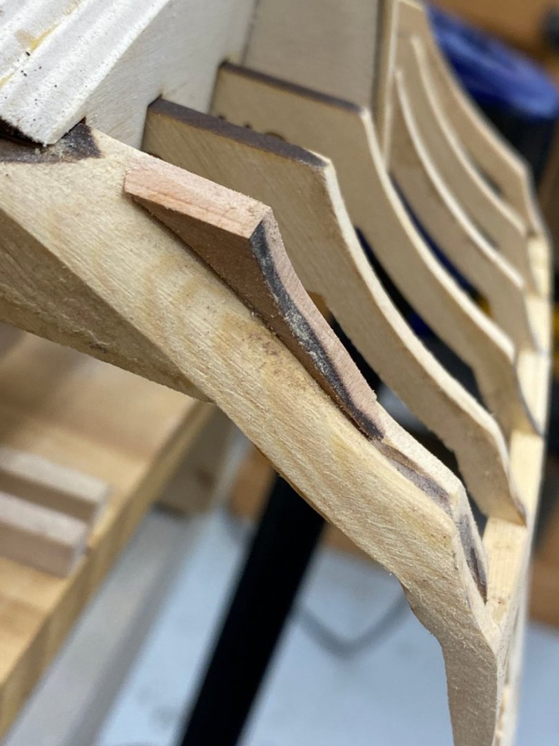
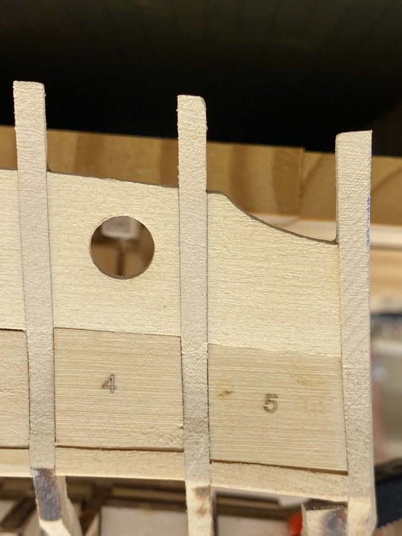
Since I had a "spare" set of the Chapter one laser cut pieces (in Cherry) I decided to sacrifice one of the "C" timbers to provide the fastest (and probably easiest) path to a piece to replace the lip on the starboard side. I had already disposed of the carrier sheet from the cedar package but could have used the Cherry carrier to outline and cut a new cedar version. I purchased the Cherry set in anticipation of switching between wood species if it seemed appropriate (or just for variety) so this seems a reasonable use of the material. In the unlikely event I should need a complete chapter 1 Cherry package I will have to fabricate one "C" timber from scratch using the other one in the package as the template - not very likely as I see things now. After cutting the timber so only the part aft of bulkhead 29 is present, the next task is to figure out how much of the timber needs to be added. Here is the new timber clamped along side the one where the material is to be added. I tried to keep the replacement aligned with the existing but that was not to easy in the confined area so I comported myself that this is going to be a pretty crude estimate anyway so just marked it when I had it " close" to aligned. After a bit of disk sander work and multiple passes with an 80 grit sanding block here is the final shape of the piece to be added. And here it is glued onto the existing timber. While waiting for the glue to set I put the window templates back in place to see how badly off the fit was now that everything has been faired (and several junctions re-glued). I took some mental gymnastics to get the figure out where template #1 should go since the hull is now upside down. Here is #1 I think this is the worst fit - I am tempted to try some light sanding on the timbers to try and get it "better". Here are #2 and 3. Both show a small gap at the bottom and #3 has a smaller gap at the top. Not sure either is large enough to warrant "corrective action". And #4 and 5 Again small gaps at the bottom of both. Probably too small to attempt to remedy. At least that is how I see things. If someone has suggestions please let me know.


- 389 replies
-
- 2
-
-
- winchelsea
- Syren Ship Model Company
- (and 1 more)
-
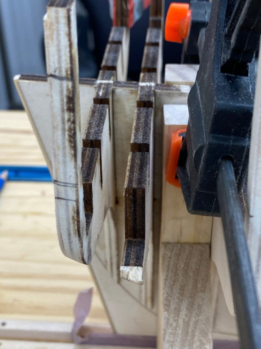
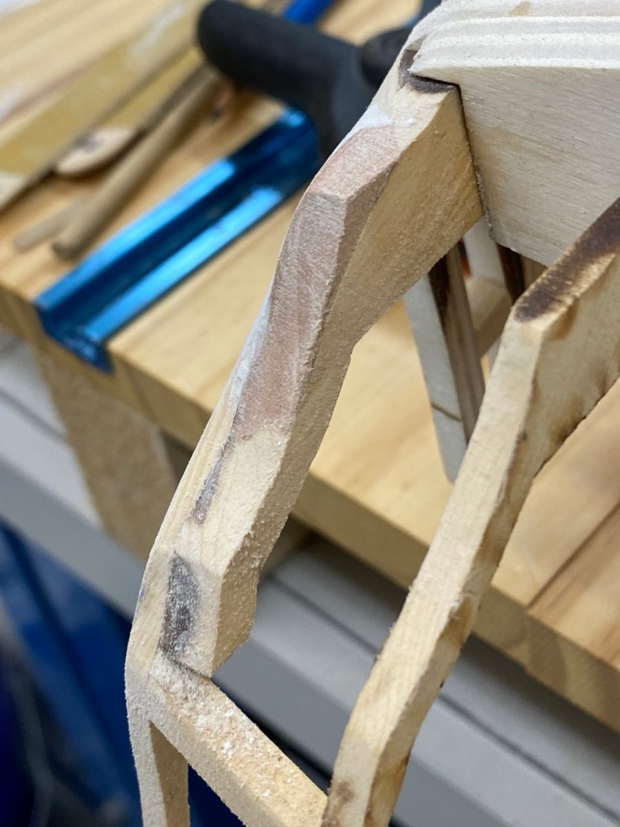
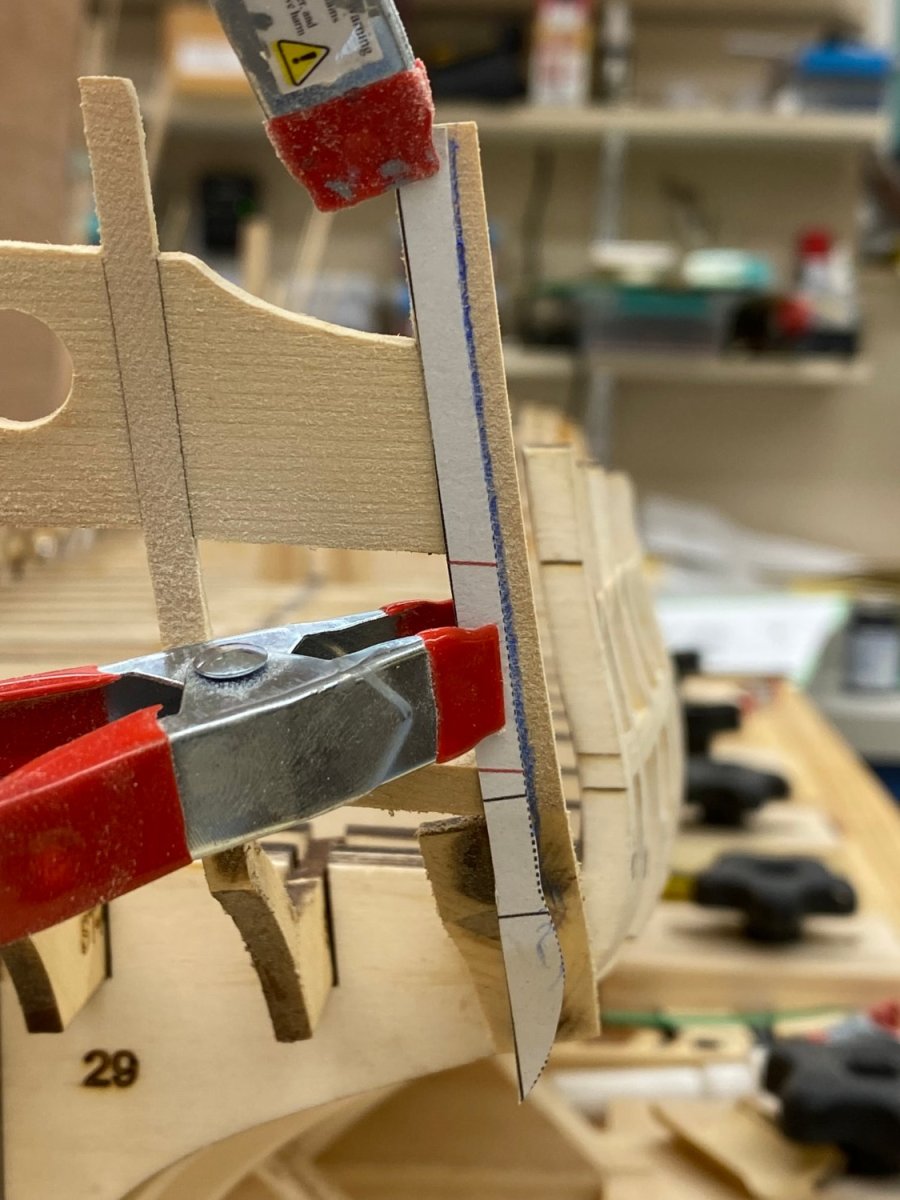
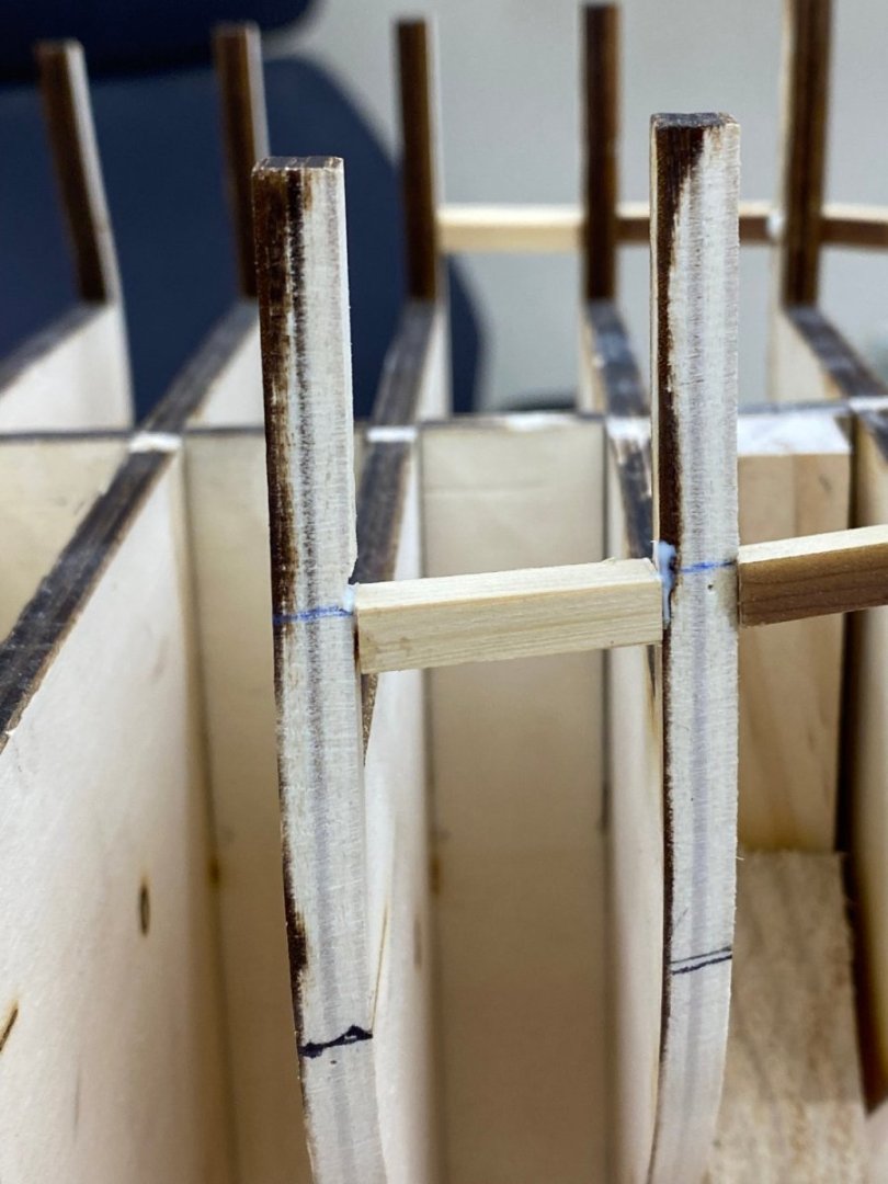
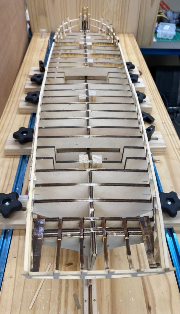
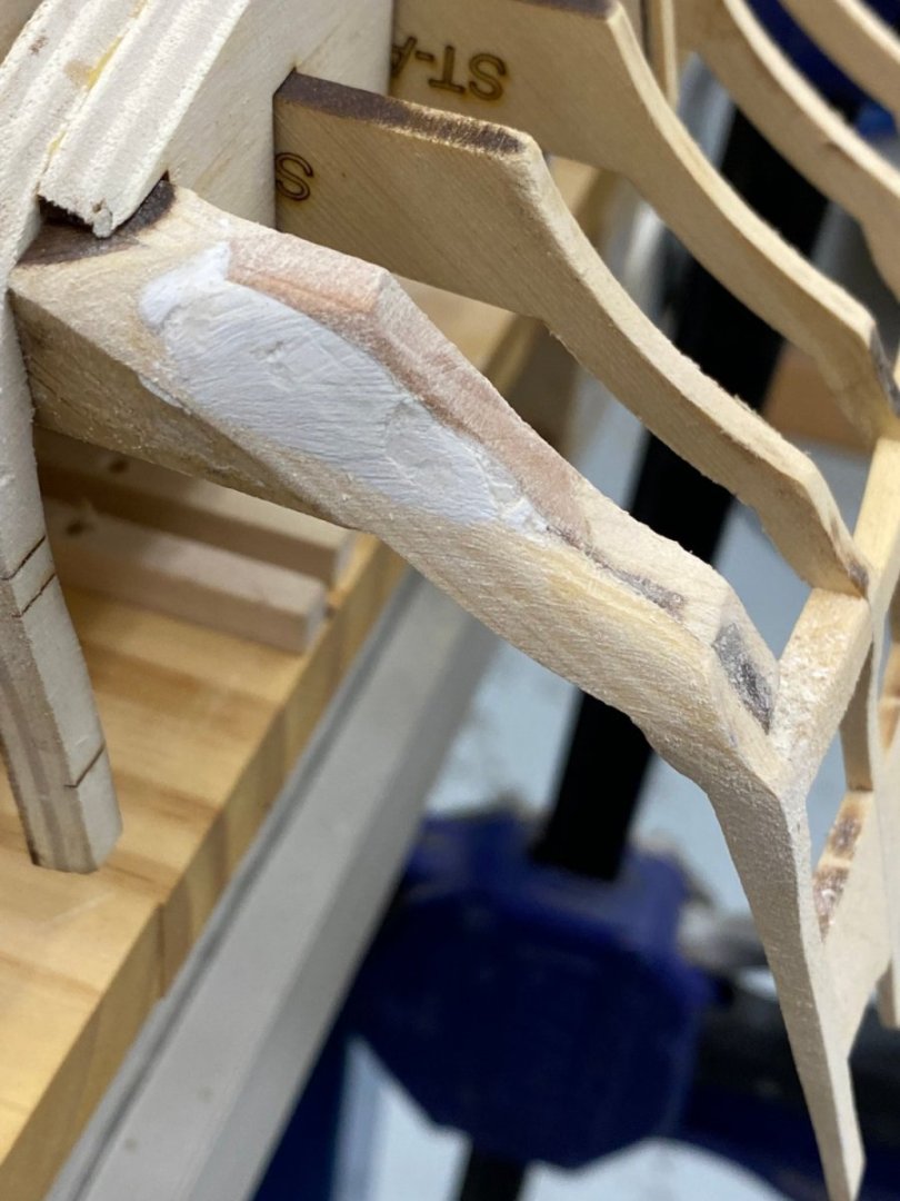
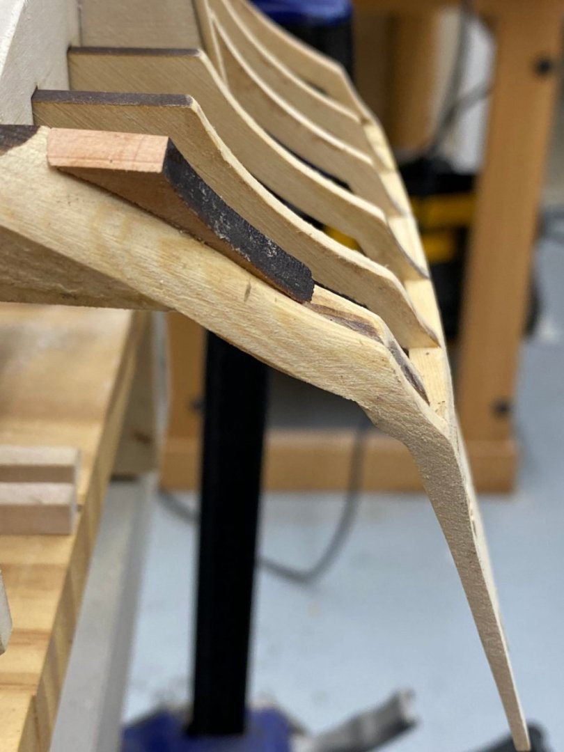
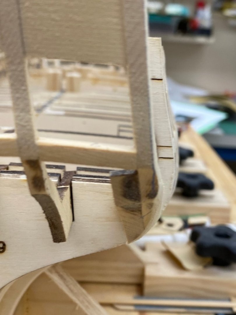
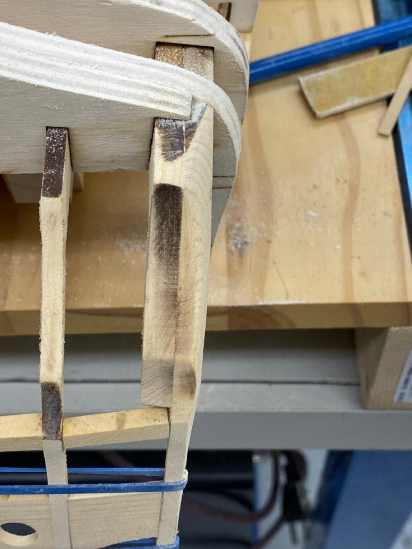
Thanks Frank. To fair the outboard timbers I cut out the stern transom template and extracted the outboard timber profile and traced it on the timbers. As Chuck had warned about not taking enough material off the timber I sanded until all of the blue was gone. In order to fair the underside of the timbers I decided it would be easier if the hull was upside down so I re-engineered the blocks I used previously and to make sure I did not impact the stern timbers, left them "hanging" off the end of the building board. The rubber bands are holding the last failed glue joint back together. I think I had to do that five or six times. For those who follow - use plenty of glue when installing the sills. Having done the starboard side I moved to the port side and am now on faced with a problem. I may have been too "enthusiastic" in the material removal on the starboard side. It appears that I have removed the "lip" where the timber transitions from curving up (if the hull is upside down) to horizontal. When I did the port side I stopped before I got that far. Here is the starboard side as it appears now. The blue tic mark is about where the "lip" would be. And here is the port side. I think I am going to have to find a way to rebuild the lip on the starboard side. Need to think about this a bit.


- 389 replies
-
- 2
-
-
- winchelsea
- Syren Ship Model Company
- (and 1 more)
-
Chuck, I think I understand about fairing the outer stern timbers. Is this the time to install the stern planking fillers?
- 389 replies
-
- 2
-
-
- winchelsea
- Syren Ship Model Company
- (and 1 more)
-
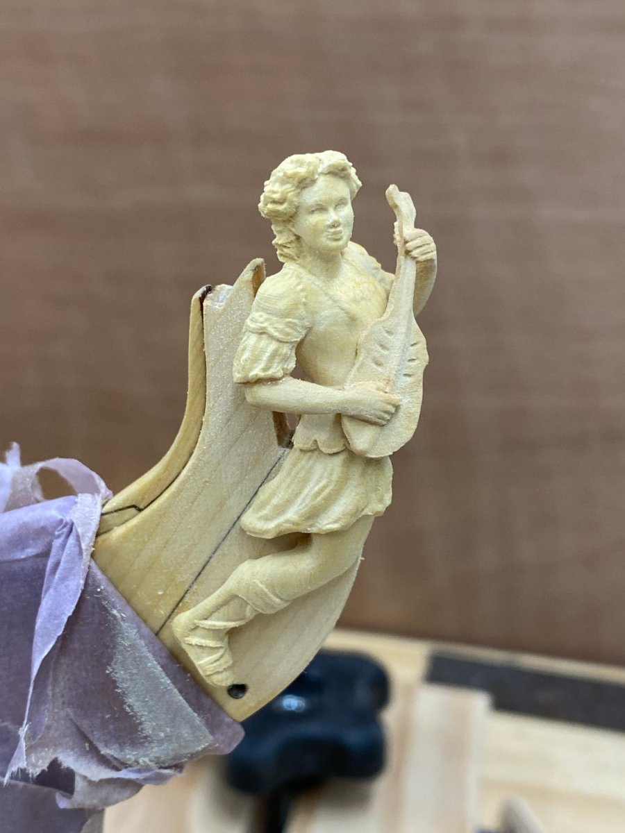
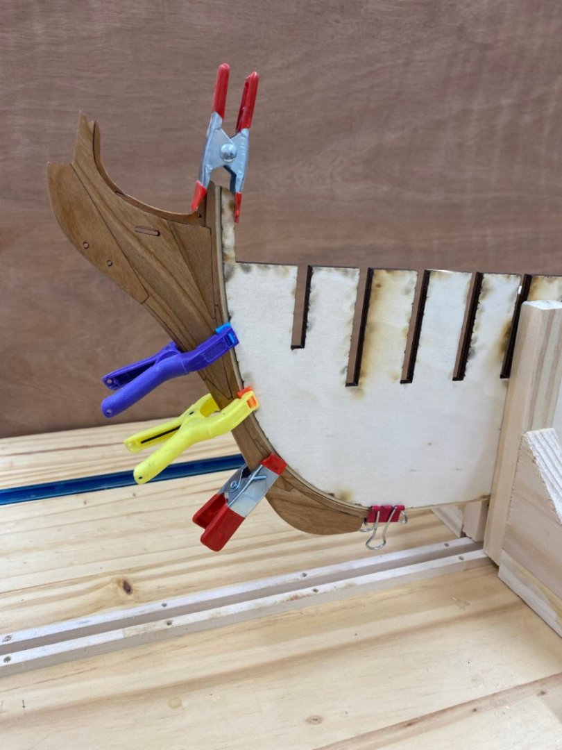
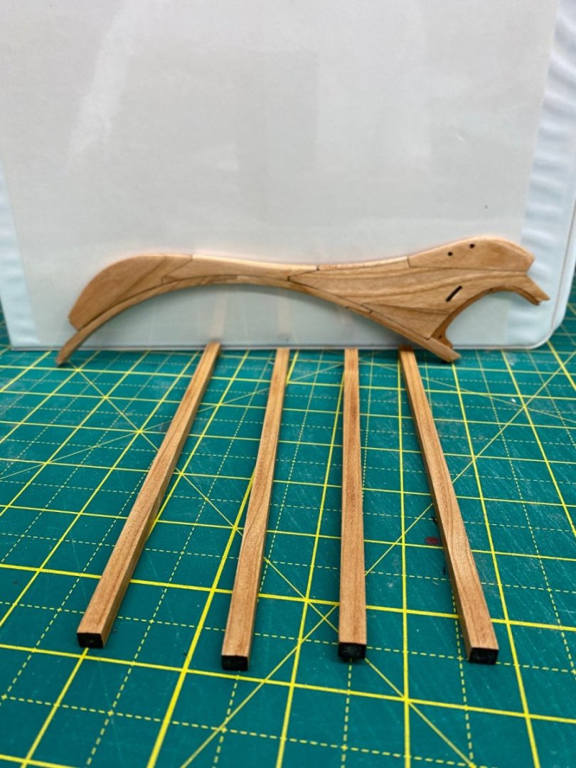
Thanks Glenn - precision is always my intention, not achieved frequently but always my intention 😀 I got the transom thinned down to close to the 3/32" mentioned in the instructions without more than three of four stops to re-glue a seam that came apart. Here it is with the template I glued to a backboard and used in the initial placement of the stern timbers. Close but not exact. Not sure what, if anything, I can or should do about the apparent mis-matches. Some are due to the perspective in the photo and I have not faired the outboard timbers to the hull shape yet. I clipped the stern transom to see if there is a problem with the window openings. Looks like the #5 lower sill is too low at the outboard edge. I will try and get a "really small shim" to fix that but will wait until I actually have the transom in its final position as I did not spend my than a minute adjusting the transom position so this may not be the only "correction" required. The next step is to fair the outer stern timbers and bulkhead 29. By the way did I miss installing the "stern planking fillers"? They are on the drawing and included in Chuck's pre-cut materials but I do not see when they are installed, clearly before planking and if this is the point where the fairing of the stern below the transom is done it would seem that they should by installed and faired in now. On another subject while I was on vacation I got the set of "decorations" in boxwood. As these are supposed to be the Porsche of Winchelsea decorations I wanted to see how the figurehead will look on the stem. I had to do a bit more sanding on get the figure to fit correctly (God forbid trying to sand the figurehead) but here is how it looks. Clearly this is the last time it will be here for a long, long time.


- 389 replies
-
- 4
-
-
- winchelsea
- Syren Ship Model Company
- (and 1 more)