HOLIDAY DONATION DRIVE - SUPPORT MSW - DO YOUR PART TO KEEP THIS GREAT FORUM GOING! (Only 72 donations so far out of 49,000 members - Can we at least get 100? C'mon guys!)
×


cdrusn89
-
Posts
1,915 -
Joined
-
Last visited
Content Type
Profiles
Forums
Gallery
Events
Everything posted by cdrusn89
-
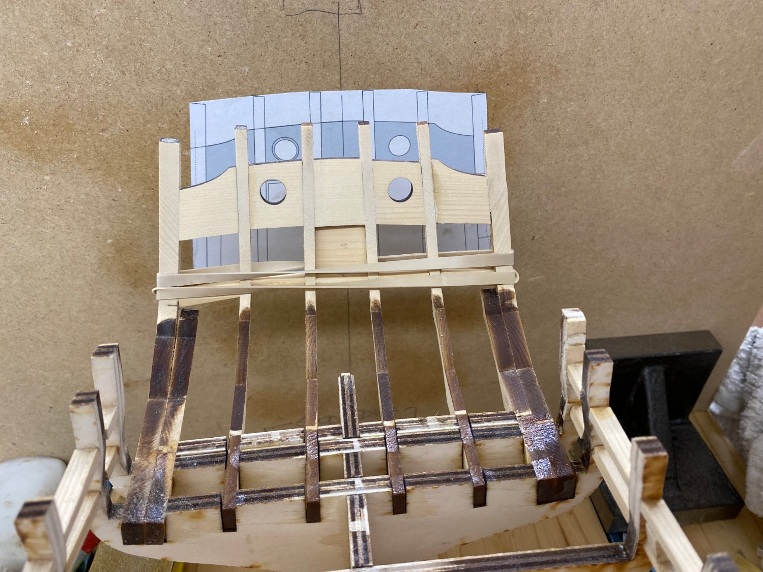
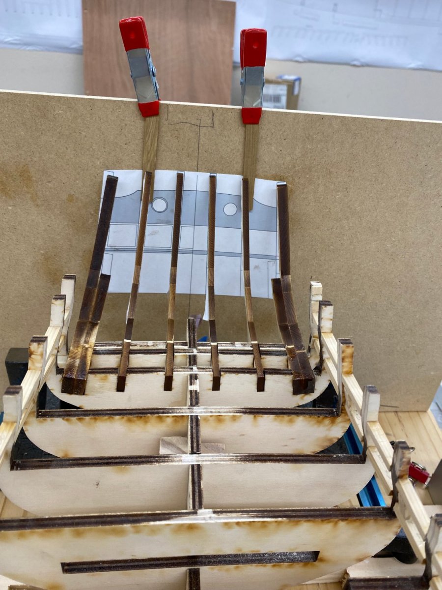
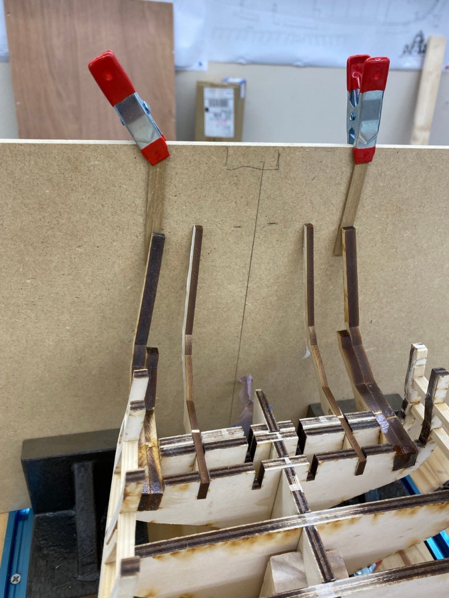
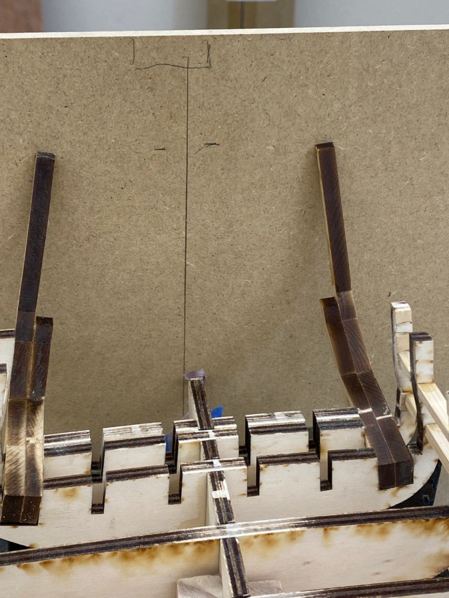
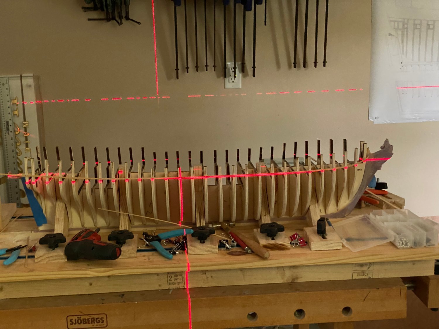
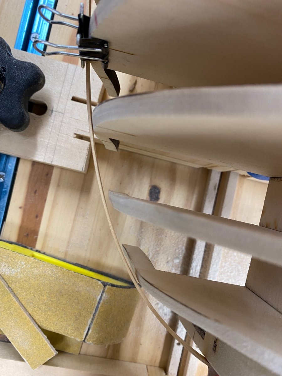
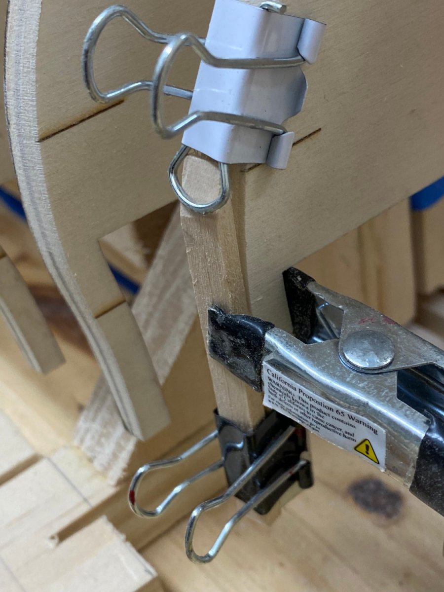
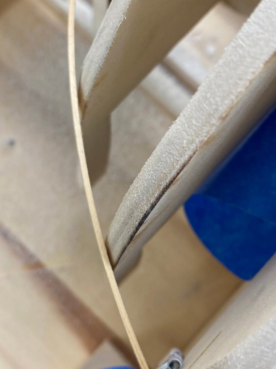
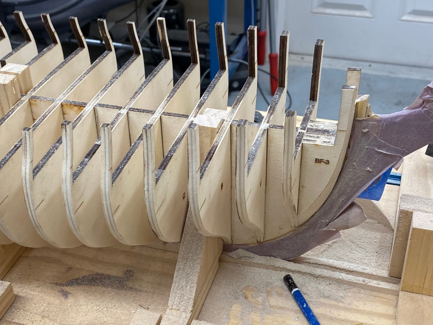
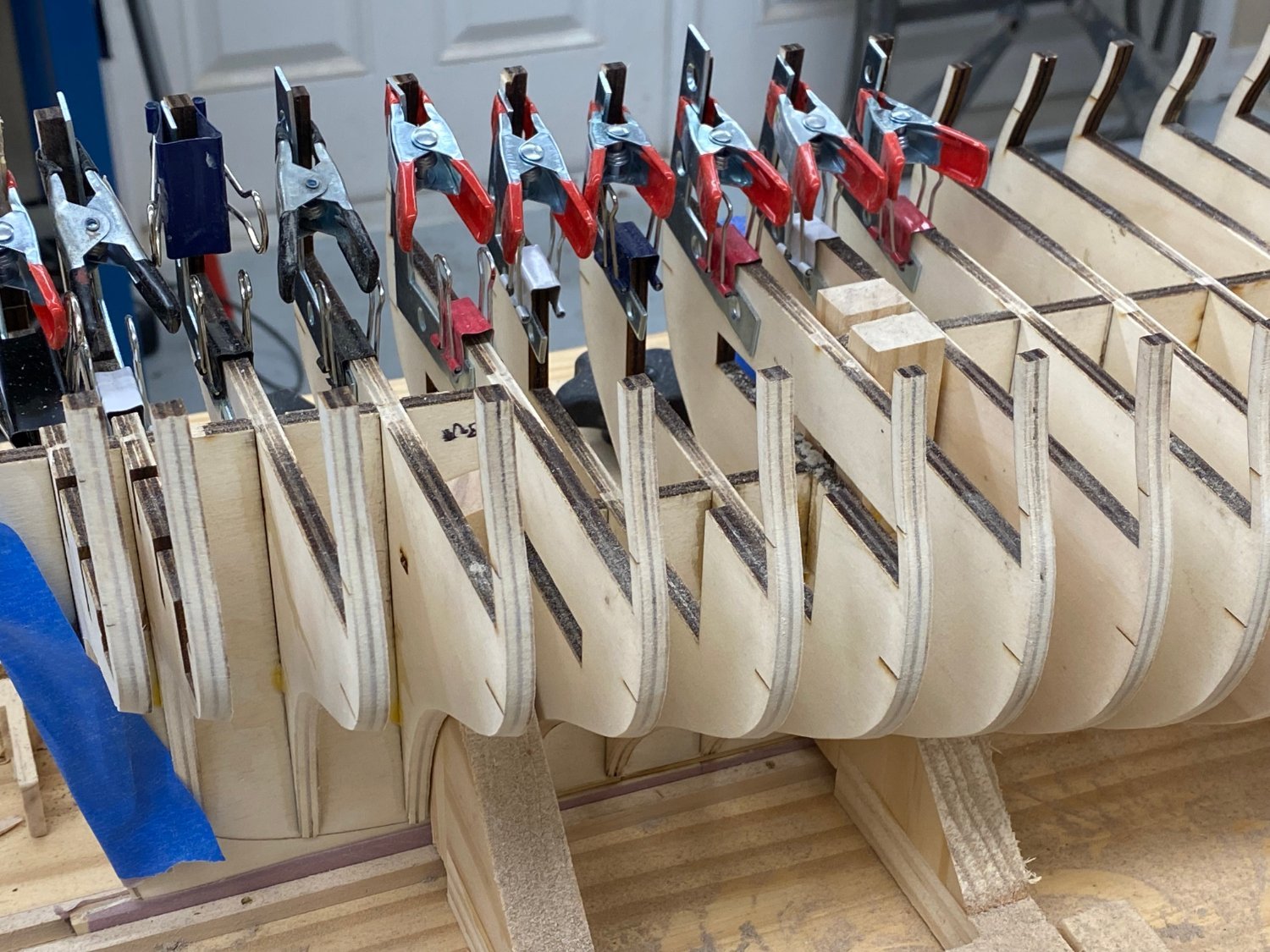
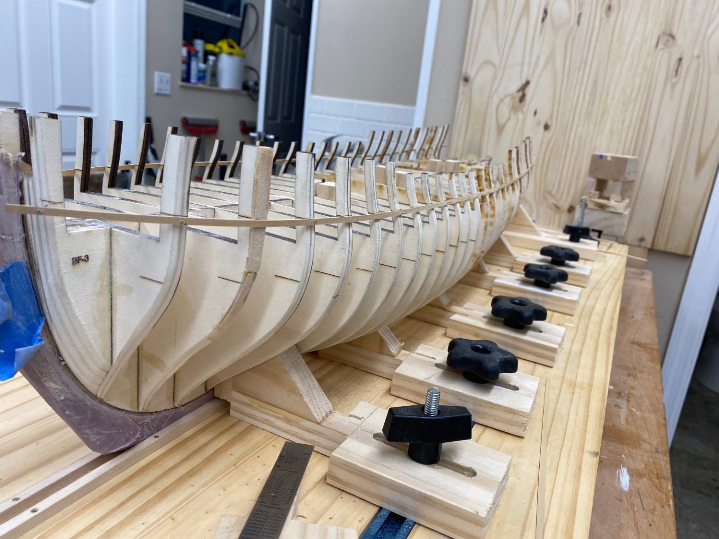
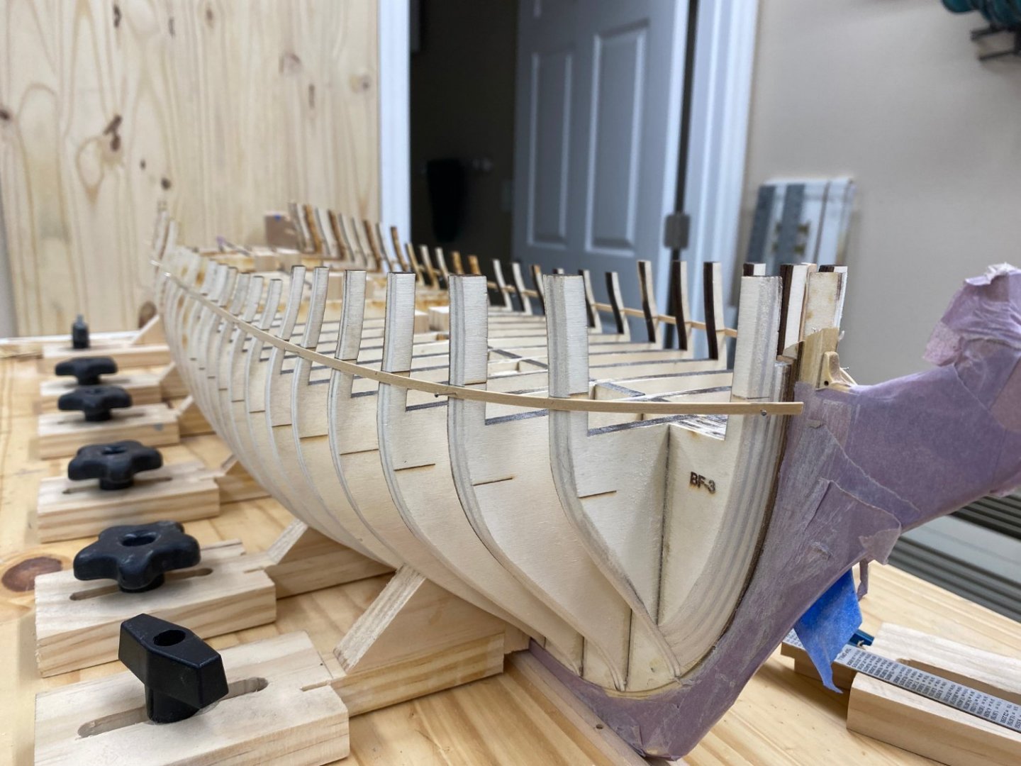
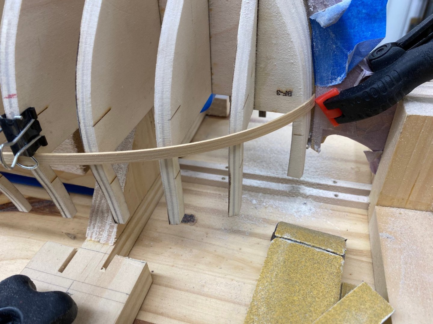
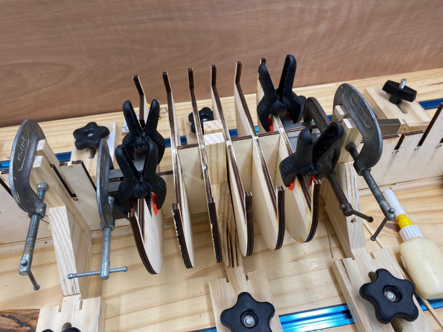
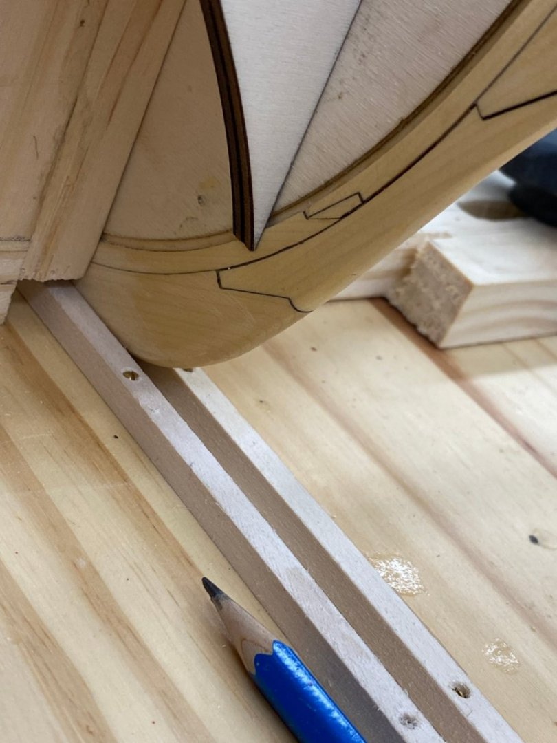
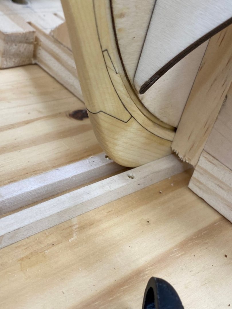
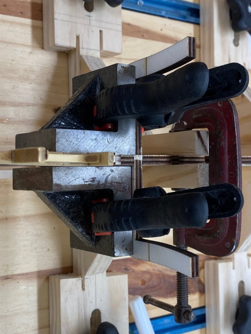
 Back from three weeks on the "Great European Tour" on Viking. Much fun but I think I saw one or two Austrian/German medieval town centers too many. Was ready to come home and face the vagaries on present day air travel. Everything turned out "okay" and on-time in the end. So back to Winchelsea transom. When I left I was so bummed out about the fit of the window frames that I ordered a new set of stern timbers "just in case" the present structure appears unsatisfactory after all the fairing is done. I have that in hand now so am going to continue fairing down to the 3/32" thickness called for and then check the window fit. One issue that has happened at least three times during the fairing to date is glue joints breaking, upper pieces twice and once on the lower. Perhaps I am being too "energetic". The rubber bands in the picture below is holding the lower sill at opening #4 in position while the glue dries. Here is a shot from the other side - the template is two inches behind the transom so it should not match up exactly. That will be one of the checks along with window fit after I get the fairing done. Latest measurement at the top of the upper sills in .1270" while 3/32" = .0938" so I have some more sanding to do.
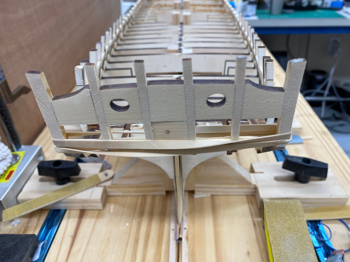


- 389 replies
-
- 9
-

-
- winchelsea
- Syren Ship Model Company
- (and 1 more)
-
Thanks Glenn. I checked four build logs last night but there was not conclusive evidence in any of them. Level with the deck it is!
- 389 replies
-
- 3
-
-
- winchelsea
- Syren Ship Model Company
- (and 1 more)
-
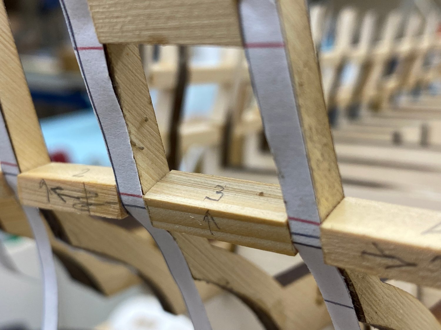
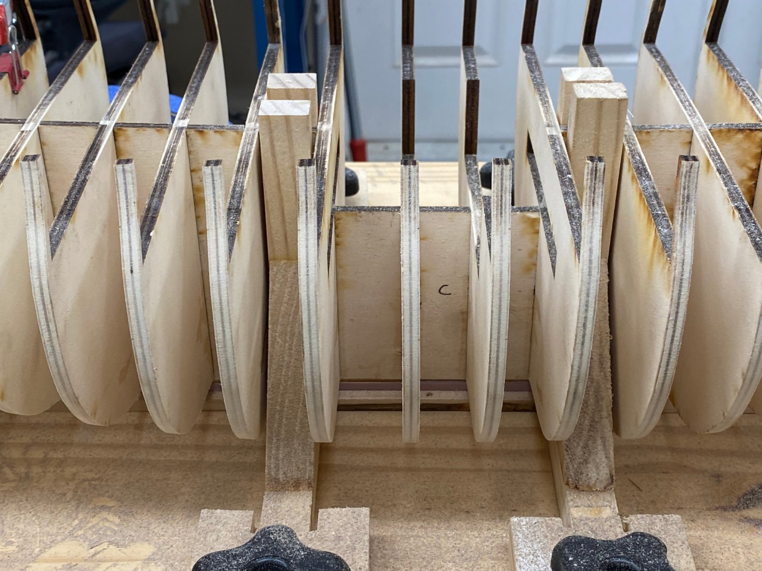
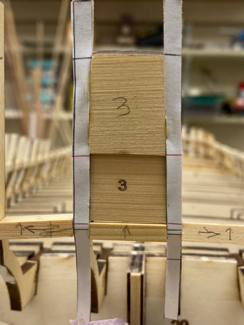
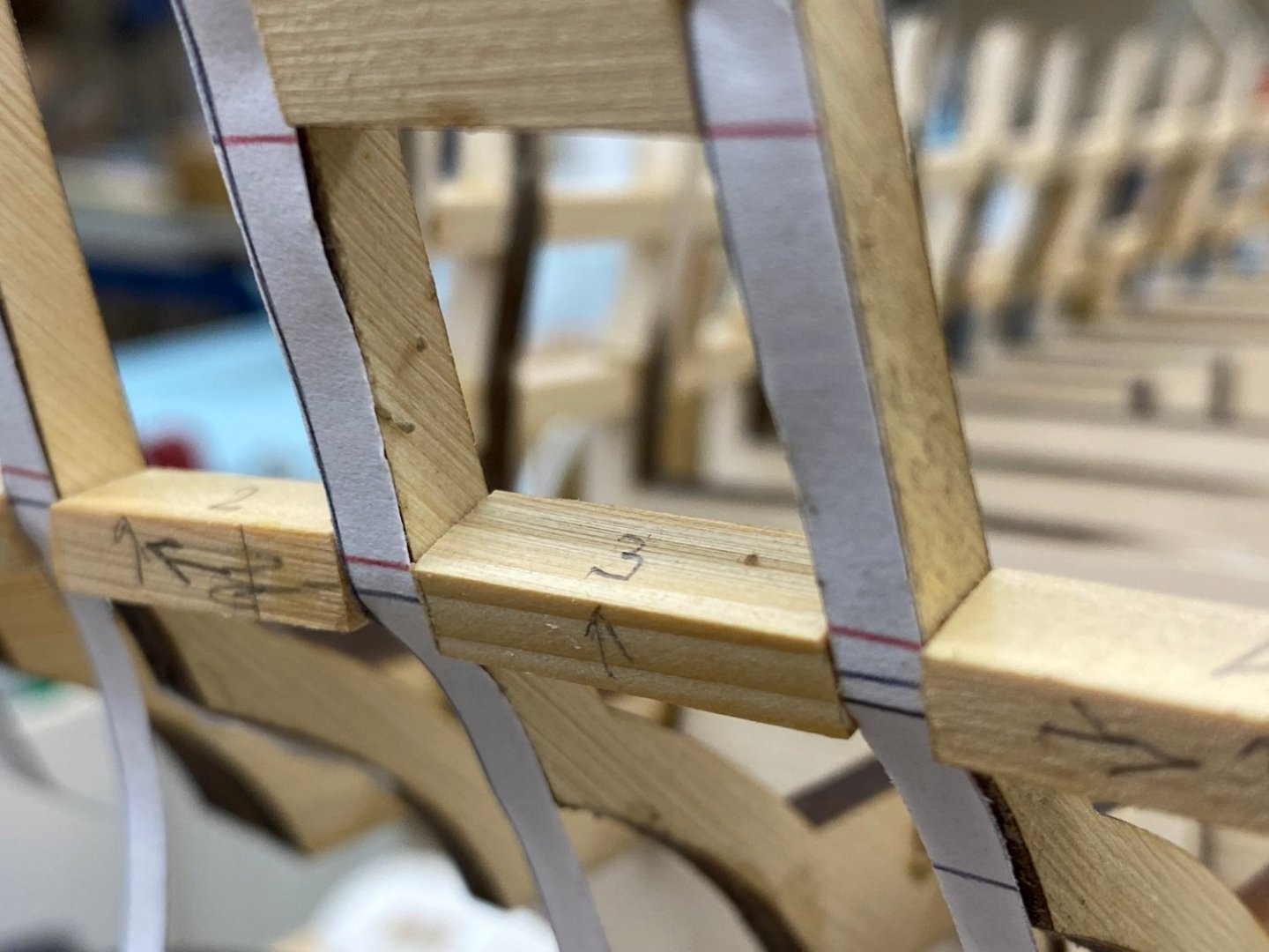
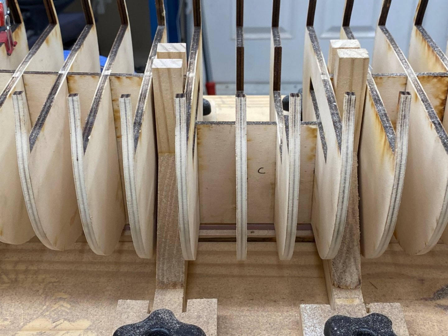
So on to gluing in the stern timber sills and top pieces. Here are the center window frame, sill and top piece in place and everything looks good so I glued to top piece in place. When it dried I thought about the lower sill and wondered whether the sill should be oriented level with the build board as the piece #2 is in the photo below or square with the face of the stern timber as piece #3 is below. The text in the instructions is silent on. the subject and the pictures aren't much help. Depending on where you look you could make a case for either. The framing plan isn't much help either. I am going to look at some other build logs but if someone "knows" the answer (or has a definitive position) please respond.
- 389 replies
-
- 5
-
-
- winchelsea
- Syren Ship Model Company
- (and 1 more)
-
So here are the stern timbers which match up pretty well with the framing template except the starboard C/D timber is a bit too far inboard. I am assuming that at least some of this will be corrected by the sills and framing but that is yet to come.

- 389 replies
-
- 4
-
-
- winchelsea
- Syren Ship Model Company
- (and 1 more)
-
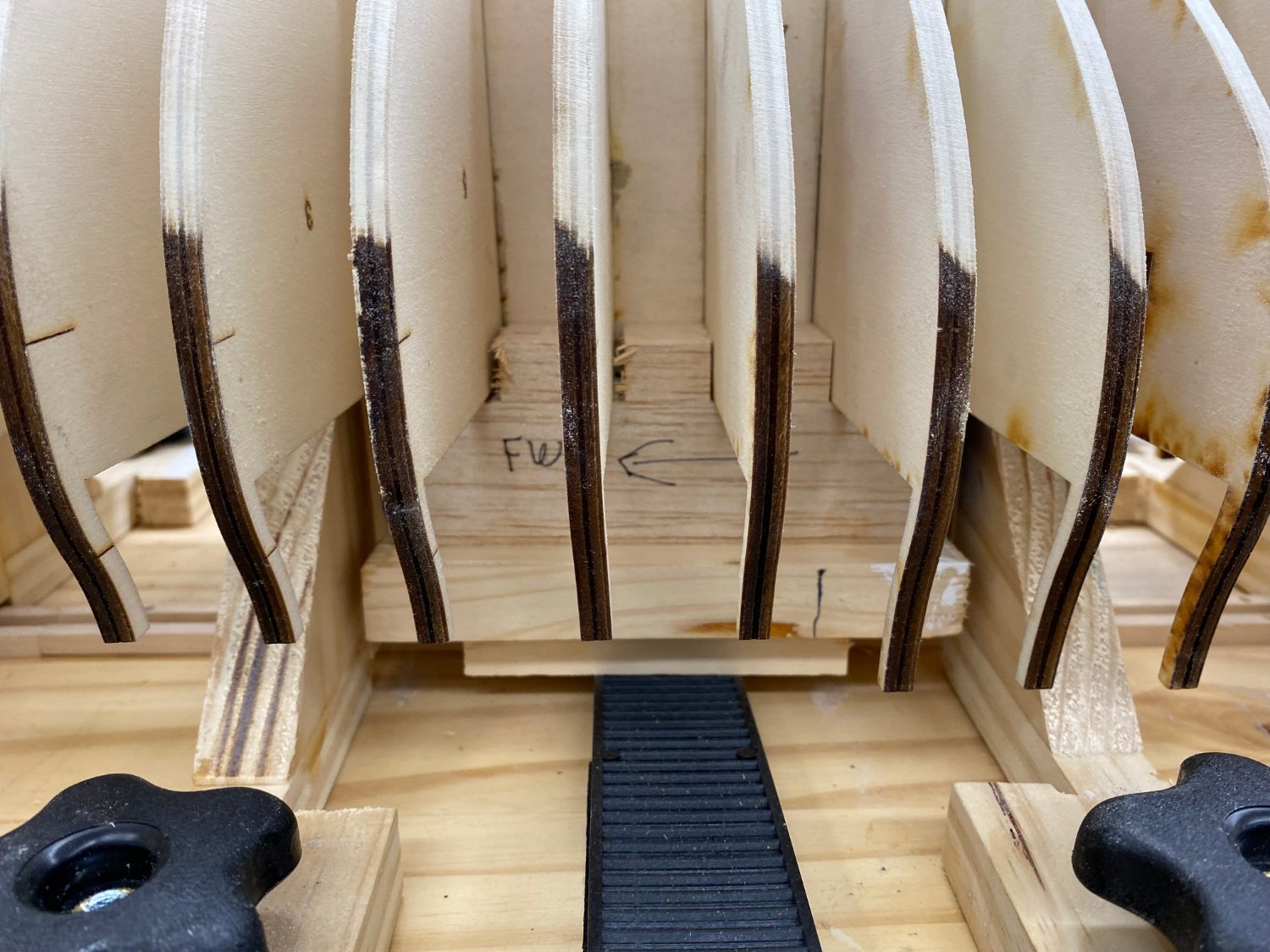
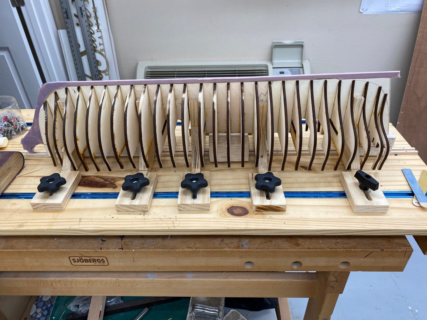
To make sure I got the B timbers 2mm aft of the C/D I got a 2mm thick piece of scrap and clamped it to the fiberboard and then moved the board back into position with the newly added pieces touching the C/D timbers. I then moved the B timbers to rest against the fiberboard and checked the measurements. The ends of the B timbers are now 2mm further aft then the C/D timbers and are ~30mm from the centerline, which agrees with the Stern Framing Plan. More thin CA and on to the A timbers.

- 389 replies
-
- 4
-
-
- winchelsea
- Syren Ship Model Company
- (and 1 more)
-
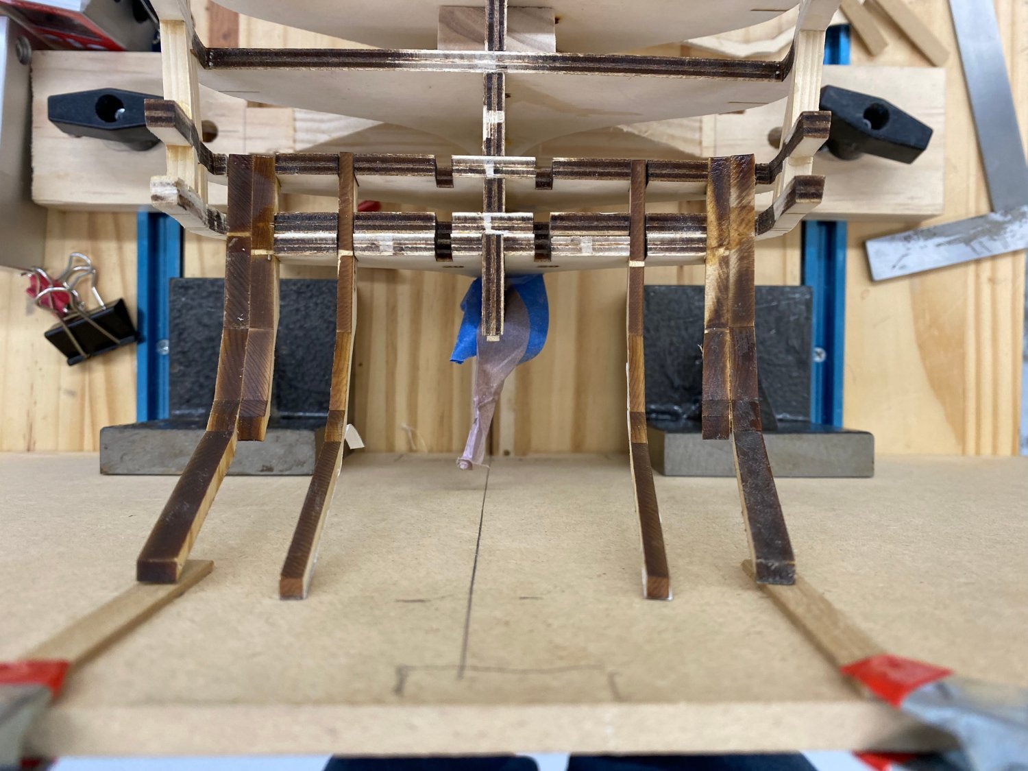
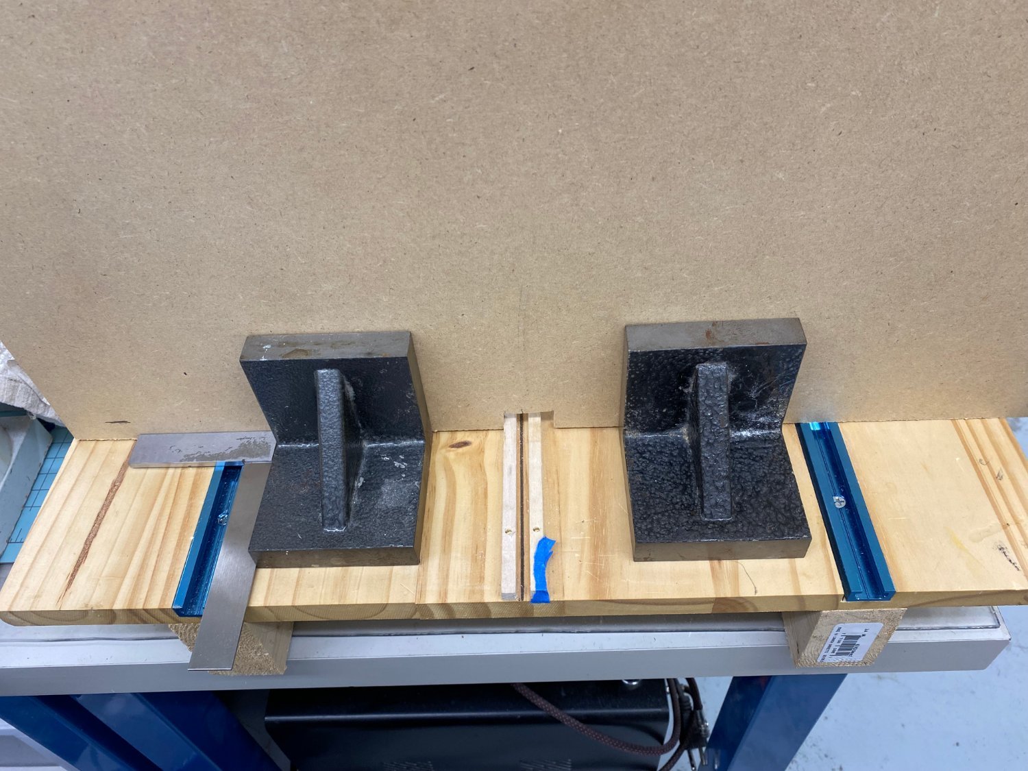
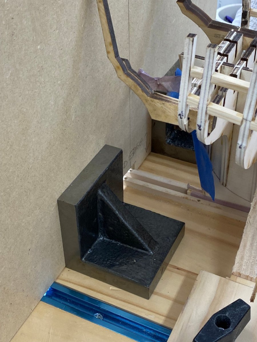
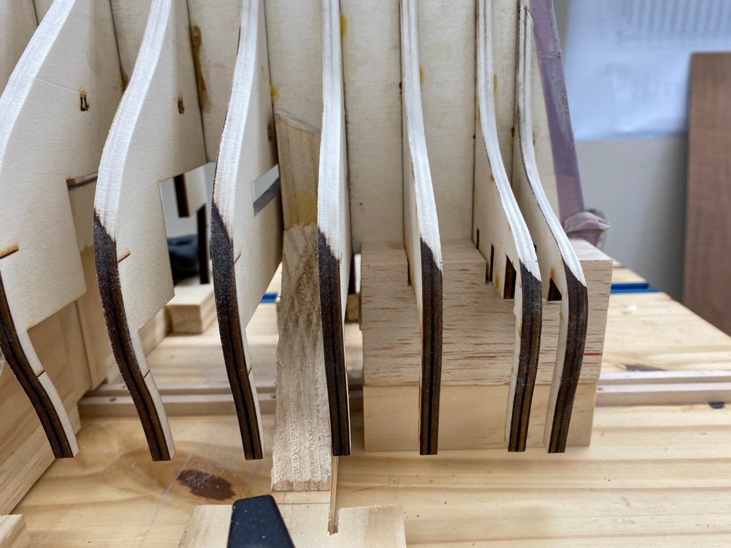
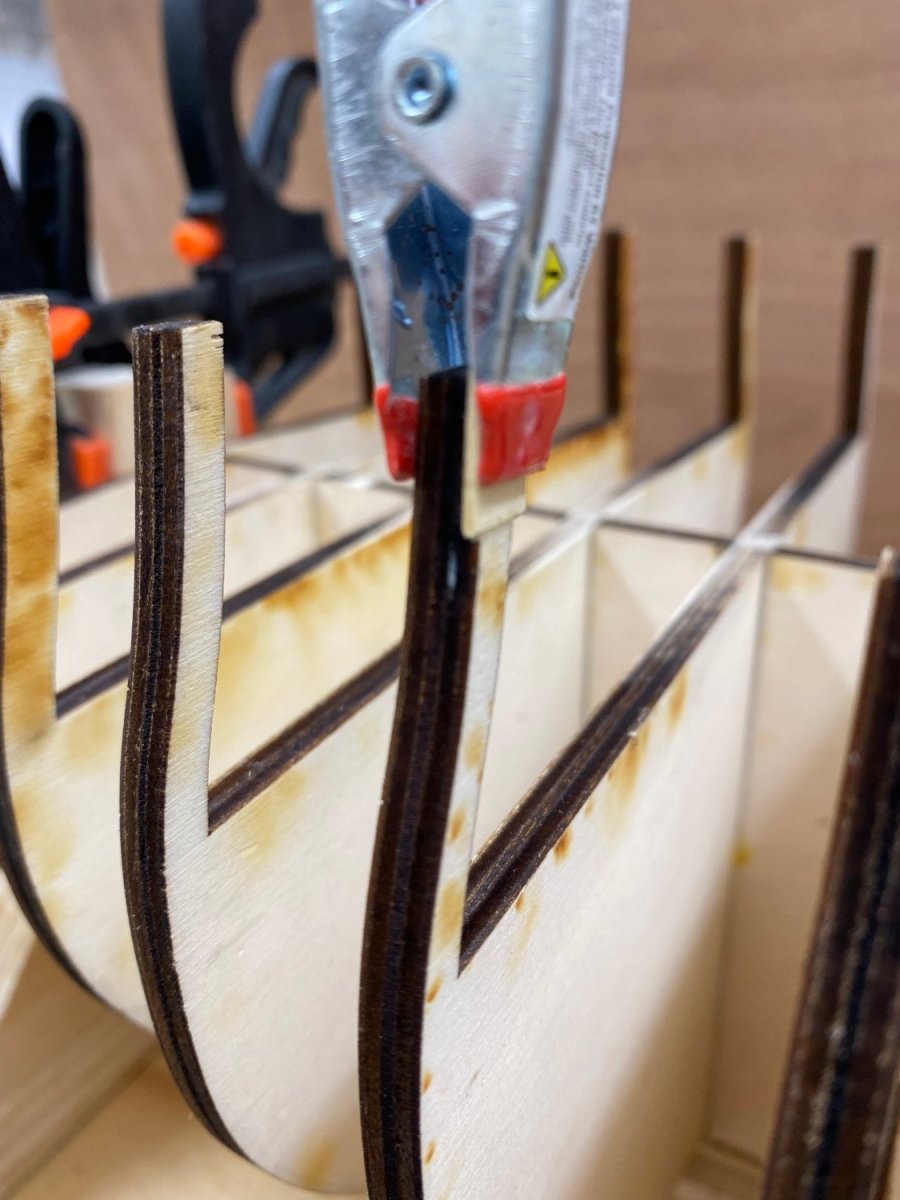
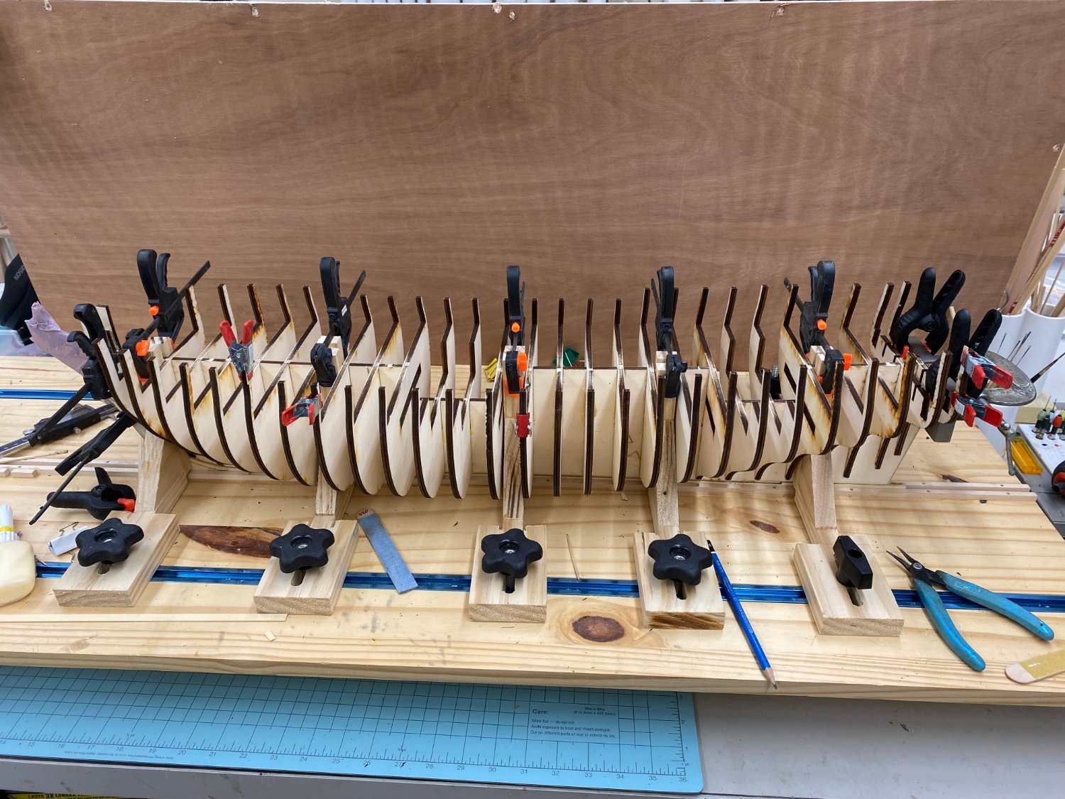
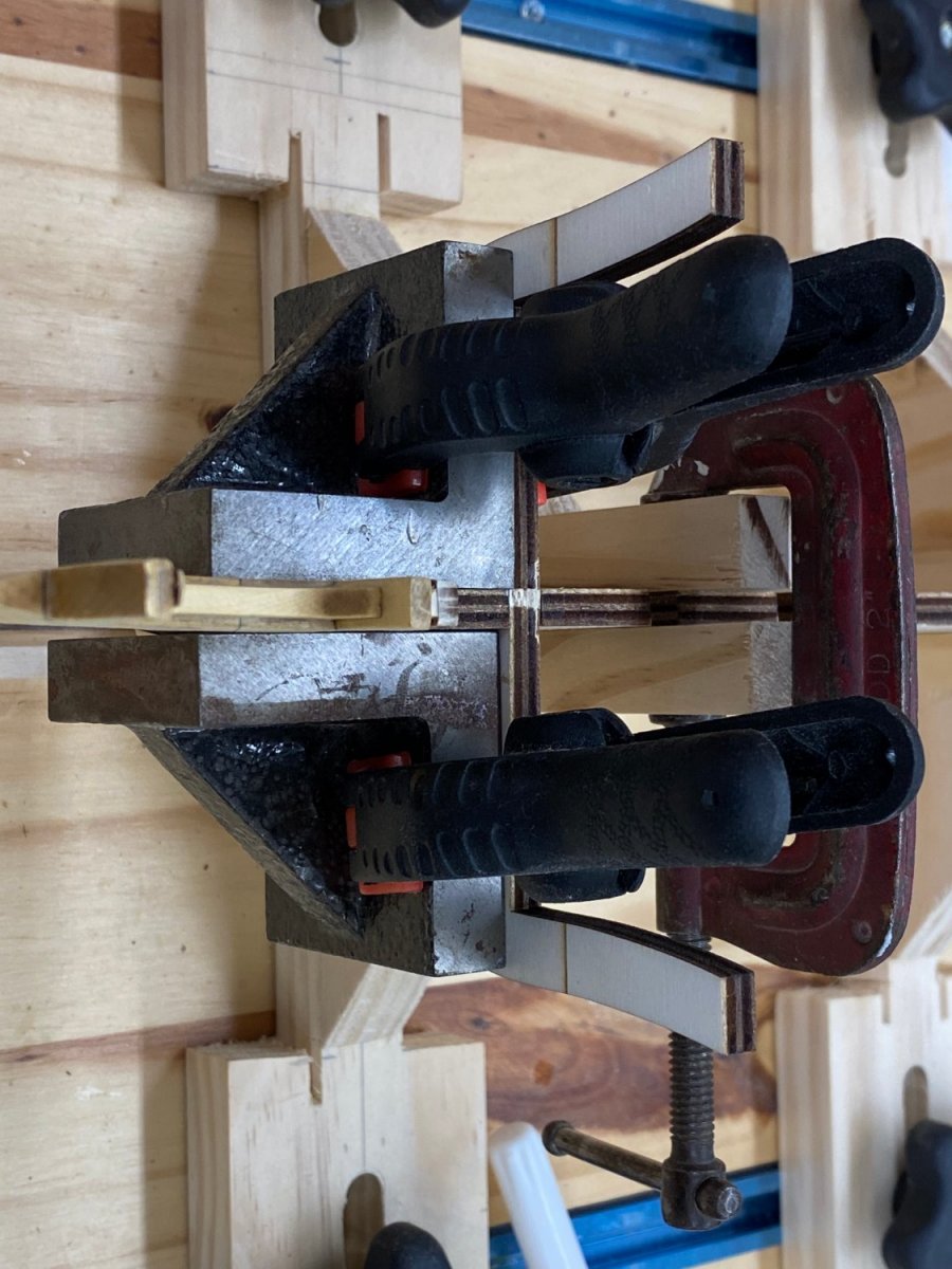
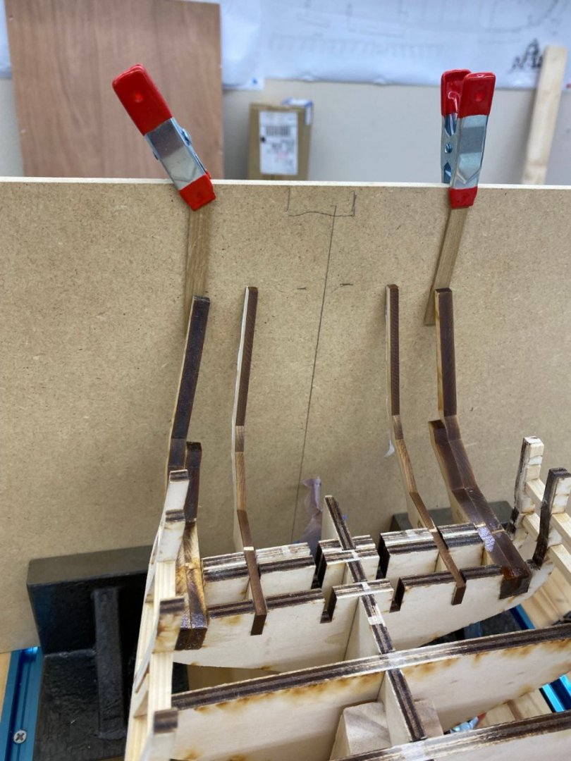
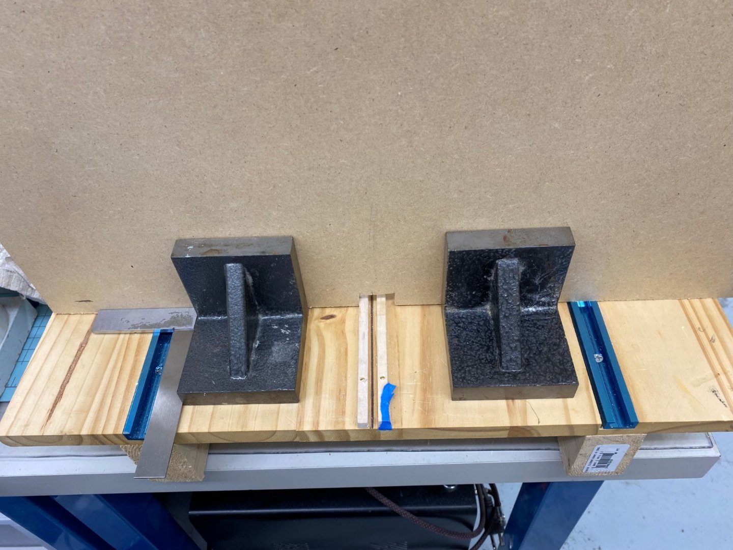
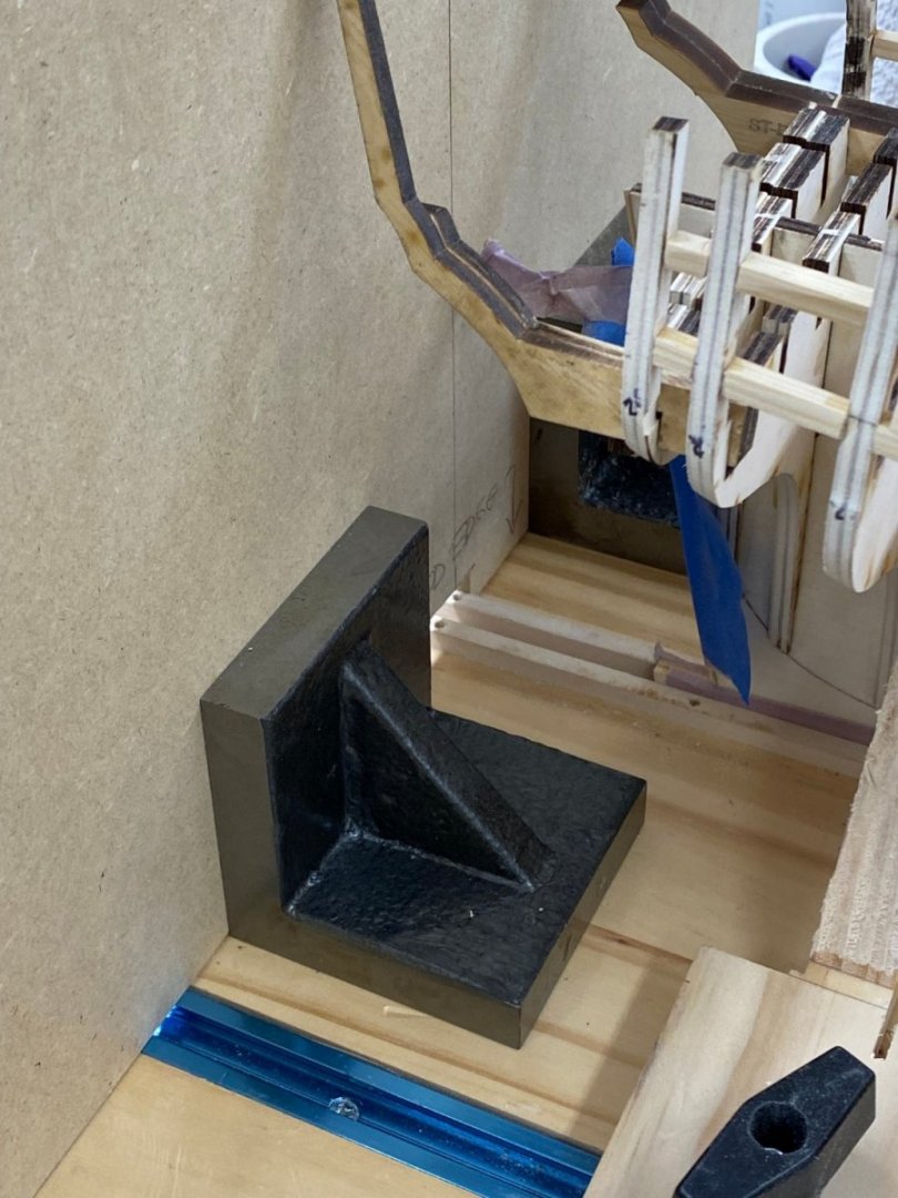
It took a good bit of thinning Stern Timbers C and D (actually I just did D so as not to disturb C location with respect to the outer hull) to get the combined C/D into the slot. I looked carefully at the slot(s) themselves and after I corrected for the laser angle they were straight so I have no explanation for why the C/D was significantly (maybe ~ 1/32") too thick to fit in the slots on Bulkheads 27, 28 and 29. I was puzzled that the instructions made no mention about the stern timbers relative location (fore/aft). The drawings seems to show that the stern is about 4mm longer at the centerline than at the outer edge. I looked at Frank Wouts' build log and saw where Chuck said that the three pairs of stern timbers provide that curve with the A timbers being the furthest aft (Dah). So with that mystery (to me) of how the stern timbers are supposed to be arranged I set about trying to figure out how to do that. Given the arrangement it seemed the best way to proceed was to anchor the C/D timbers first since they are furthest forward and are the hardest to adjust since the support is across three bulkheads with a notch to boot. The A and B timbers are essentially just in slots so they are easier to adjust. With only 2mm of fore/aft spacing between the pairs of stern timbers it is going to require more than a "seaman's eye" to get the timbers in the right places. So I built a "jig" composed of a piece of (flat) fiberboard and four machinist blocks to give me a surface to mark where the stern timbers are located. If I had a handy piece of squared paper I would have glued it (contact cement) on to help with locations but... So here is the jig with the C/D timbers in place. I measured and both C/D timbers are equidistant from the centerline and the same height above the keel (aka build board). Just to be sure everything is level I put a digital level on the hull and got a 0.00 reading with the sensor on bulkheads 17 and 19. So now I glue the C/D timbers in place (with thin CA so I do not have to move anything) and move to the B timbers which should be 2 mm further aft than the C/D timbers.


- 389 replies
-
- 6
-
-
- winchelsea
- Syren Ship Model Company
- (and 1 more)
-
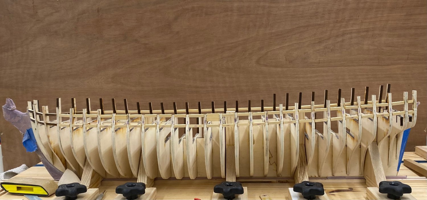
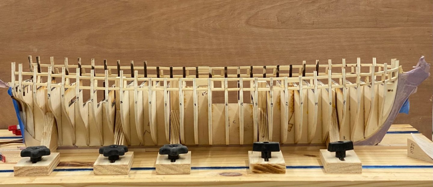
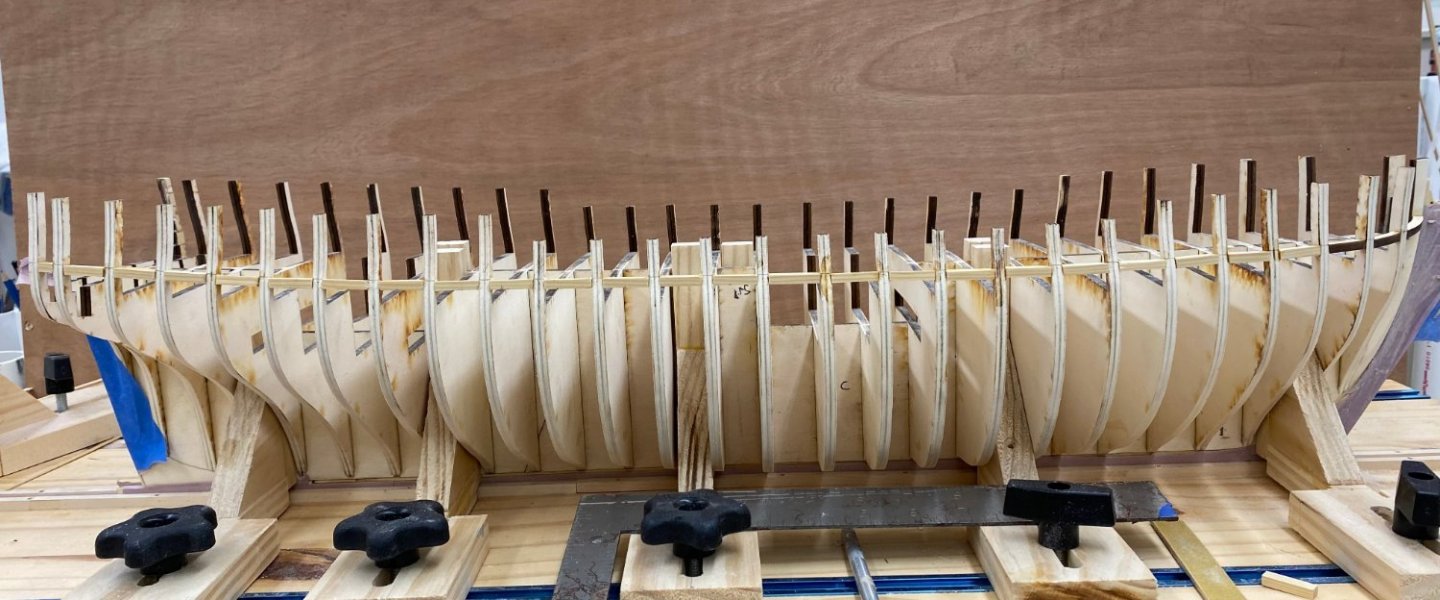
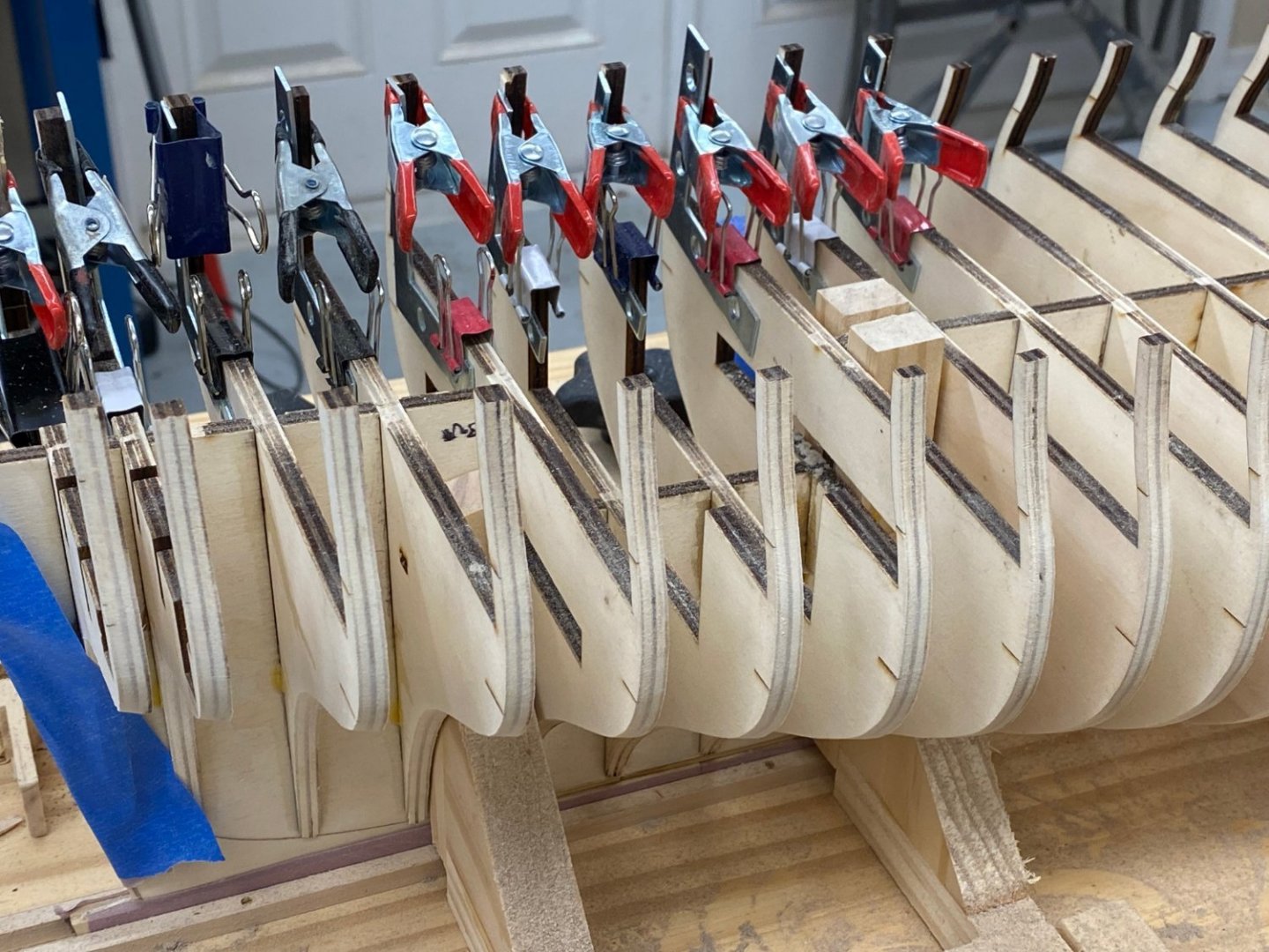
Gunports completed on both sides and fairing completed. I took this opportunity and did some fairing/thinning on the inside as well, especially at the bow as that is necessary before adding the bollard timbers. Stern timbers next - should be interesting.
- 389 replies
-
- 6
-
-
- winchelsea
- Syren Ship Model Company
- (and 1 more)
-
Upper sills done on port side. I got kind of carried away and put an upper sill across every bulkhead, not just those shown in the plans. Hopefully I will not regret this later but I think it will give the hull structure more stability during the additional fairing to come. I am torn between fairing this side and then doing the upper sills and fairing on the starboard side or doing the starboard upper sills now and then fair both sides. I will consider that while I take my afternoon nap.
- 389 replies
-
- 4
-
-
- winchelsea
- Syren Ship Model Company
- (and 1 more)
-
Port side lower sills complete. I used a T-Square on the build board to check that the sill was correctly oriented, i.e. that the sides facing port and starboard are vertical and thus that what will become the bottom of the gun port is not tilted inboard or outboard. I tried "eyeballing" it but when I measured I was consistently off, usually with the sill tilted inboard. Now on to the top sills and other upper "pieces".
- 389 replies
-
- 4
-
-
- winchelsea
- Syren Ship Model Company
- (and 1 more)
-
Thanks Frank, I used balsa fillers on the Charles P Notman (BlueJackets 1/96 scale kit) for most of the hull so I am familiar with the "balsa bulge" that occurs if you are not careful. Almost done with the lower sills. As the instructions say " building the skeleton and framing is not much fun".
- 389 replies
-
- 1
-
-
- winchelsea
- Syren Ship Model Company
- (and 1 more)
-
Starboard side lower sills installed. The ones forward are much easier than those aft. Some of them are angled in two dimensions - a challenge to get fitted correctly. Good thing Chuck includes seven lengths of the 3/16" X 1/4" cedar. I went through two plus pieces getting this far.
- 389 replies
-
- 6
-
-
- winchelsea
- Syren Ship Model Company
- (and 1 more)
-
Glenn, Thanks I have the balsa ones ready to install when I get the hull upside down after the upper wales planking. Yes, when I put the laser level on the plans that sweep of the gun ports is very evident. Hopefully I can faithfully follow that line with the port sills.
- 389 replies
-
- 2
-
-
- winchelsea
- Syren Ship Model Company
- (and 1 more)
-
I looked ahead to Chapter 4 where the false deck is installed and it looks like filler blocks up to the level of the deck will not be a problem so I am going that route.
- 389 replies
-
- 1
-
-
- winchelsea
- Syren Ship Model Company
- (and 1 more)
-
Thanks for the "comeback" Frank. I have been considering using balsa for the fillers but am not sure how far up the gap I should carry them. I saw that you stopped at about the lower mark on bulkhead W. I was thinking about going all the way up to the top of the bow fillers/bulkhead W deck level but am not sure if that will cause some problem later.
- 389 replies
-
- 1
-
-
- winchelsea
- Syren Ship Model Company
- (and 1 more)
-
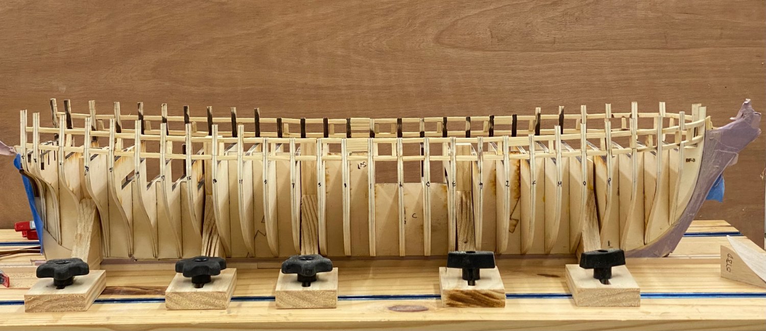
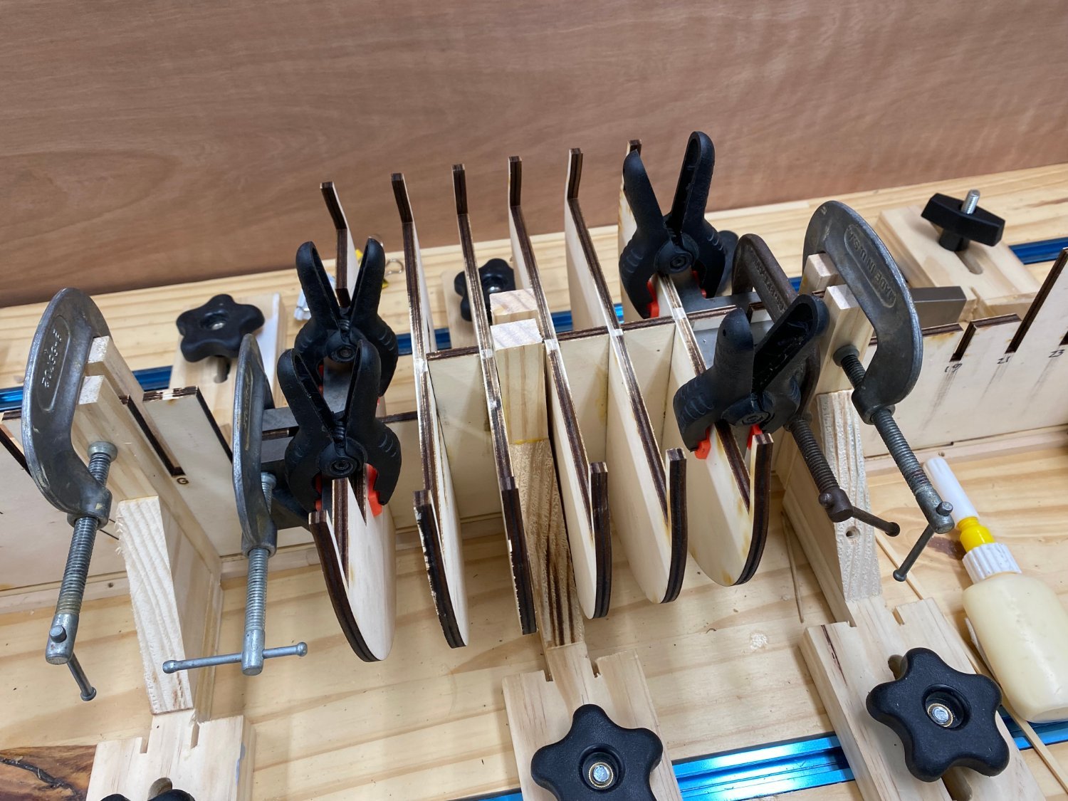
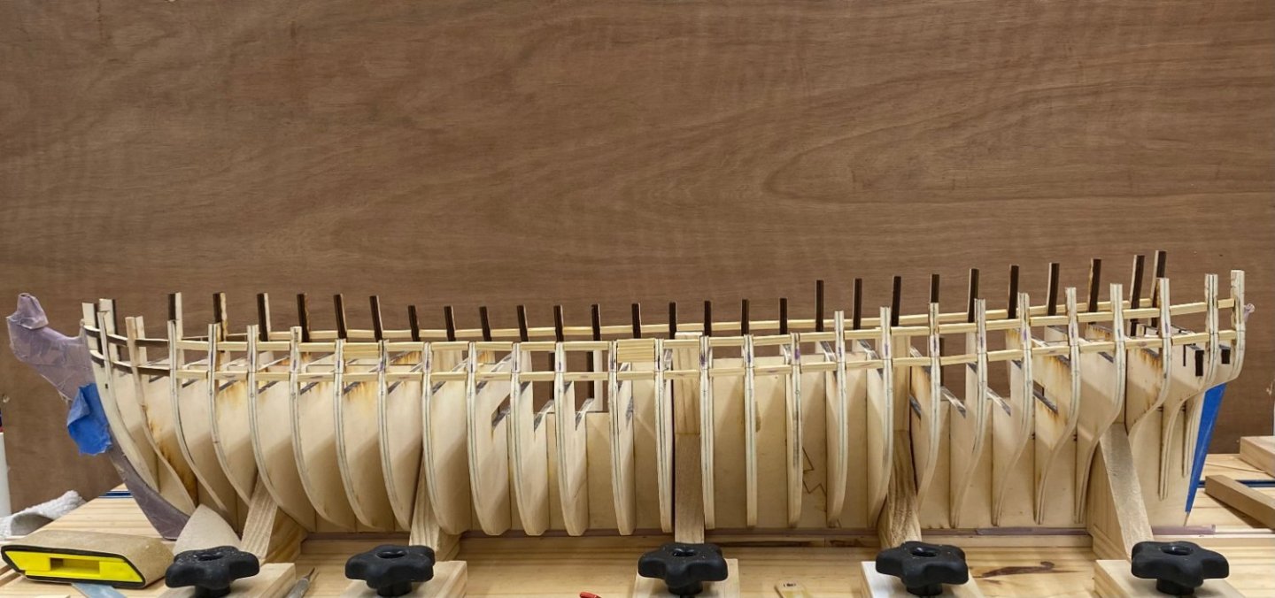
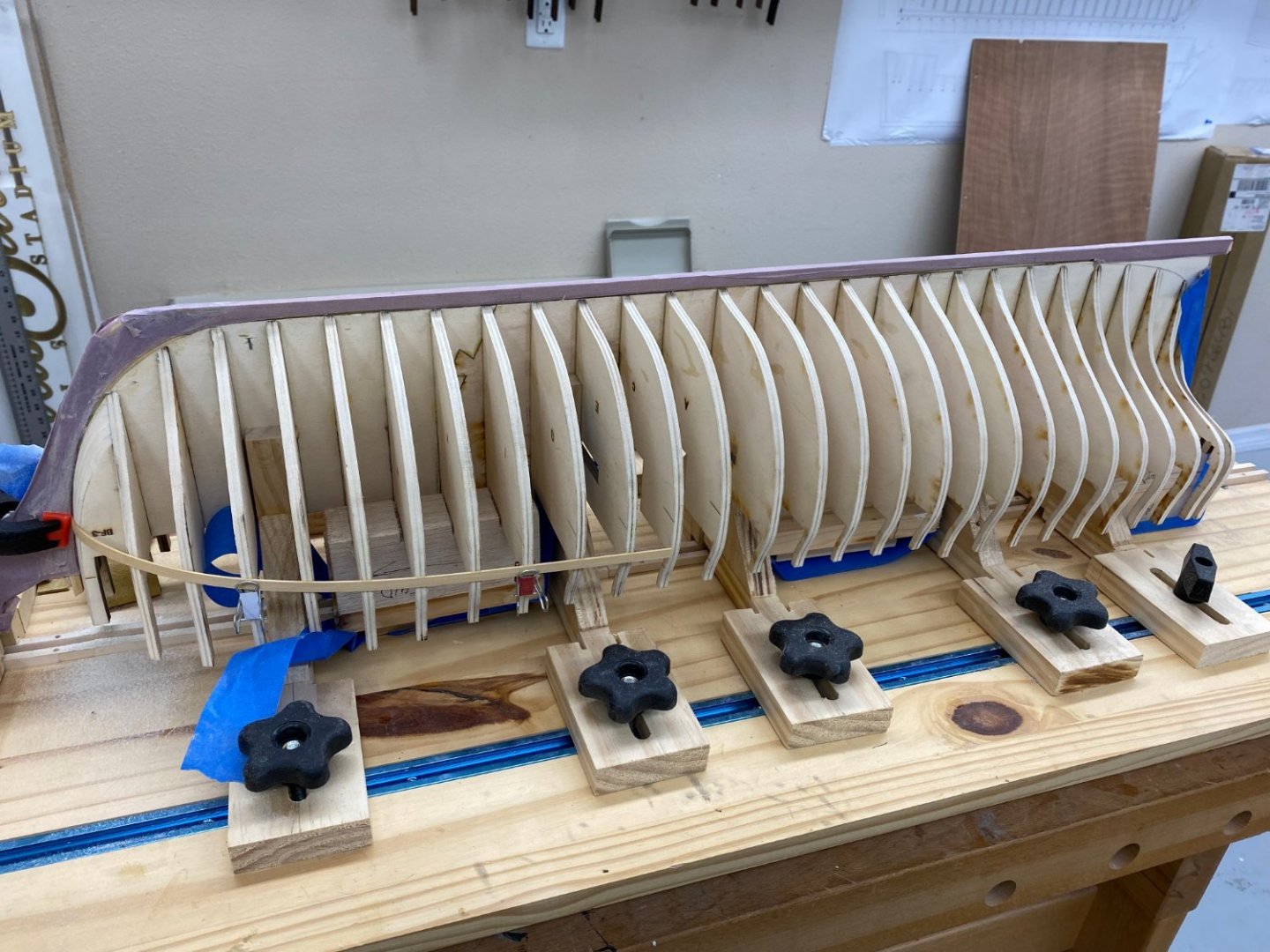
Batten installation competed. Checked both sides again and made two adjustment of less than .1" each. Here are two shots with the battens installed. Off with the battens and on to the port framing.
- 389 replies
-
- 9
-
-
- winchelsea
- Syren Ship Model Company
- (and 1 more)
-
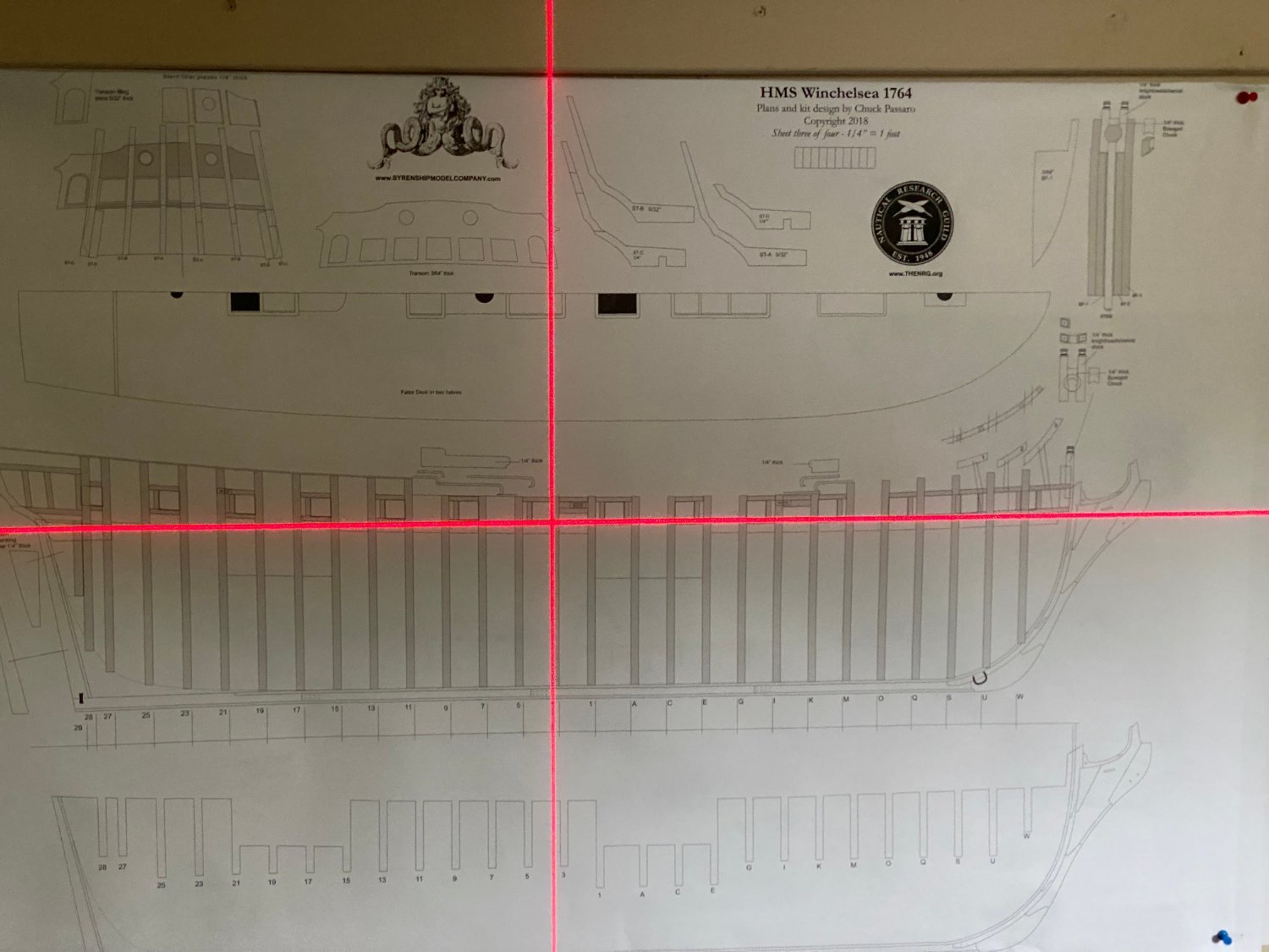
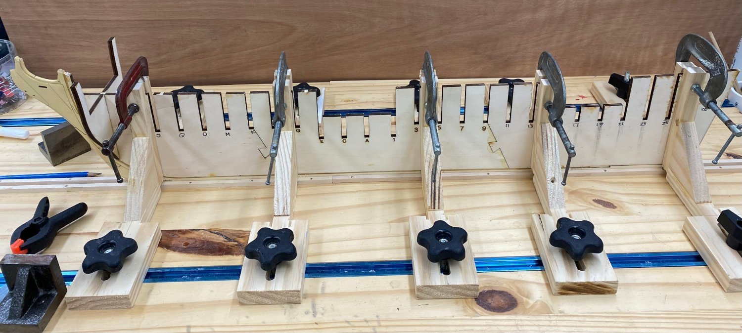
Thanks Rusty - yes much better to find it now. With the bulkhead U issue resolved (as best I can tell at this point) it is time to put the lower sills in. I thought it might be useful (for me) to see how the marked lines line up with the plans. So I pinned a batten (1/32 X 1/8 boxwood which I have in 24" lengths, the longest AYC batten I can make is about 12") on the marks and set up the laser level to see how it looks. I centered the laser on bulkhead 3 and the batten at that point. As you can see the laser follows the batten for about 9 -10 bulkheads going forward and 1 -2 going aft. Then I set the laser up an the plans which are on the wall to see how this compares with the plans. Admittedly it hard to see in the picture so you will have to take my word that they agree very well. And that is assuming that I have the build board, model, and drawing level which, of course, I have tried to ensure that but.. So now to try the other side and then inspect the batten runs to see if there are any "irregularities" although given the above I kinda doubt it.


- 389 replies
-
- 6
-
-
- winchelsea
- Syren Ship Model Company
- (and 1 more)
-
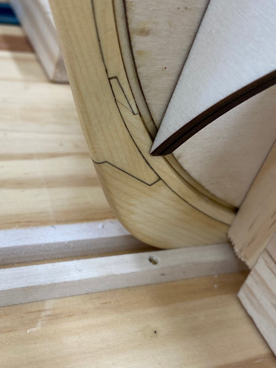
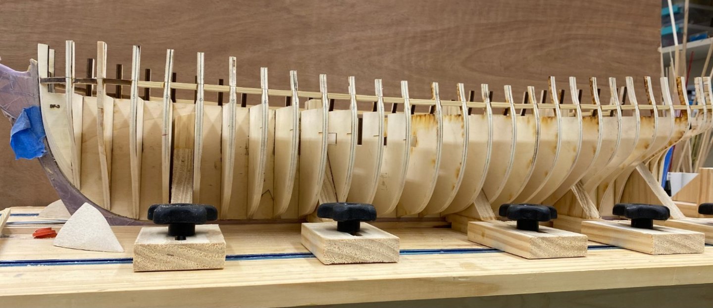
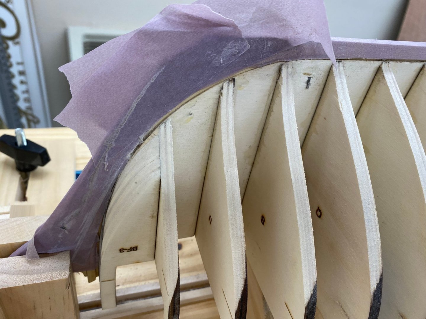
So I finished the fairing, at least I thought so. While checking the lay with a 3/64" X 1/4" piece (general size of the planking) I found that I had been a little over zealous on bulkhead U (second one from bow) on the port side. You can see the gap between the batten and the bulkhead below. And there is a small gap at bulkhead W but I think that may disappear if bulkhead U is fixed first. Here is where the batten is located for reference. So I glued a piece of basswood (make sanding easier) 3/32" X 1/4" to the top portion of the bulkhead (mostly the bulkhead extension) and will CAREFULLY adjust this to get a better fit at bulkhead U. Then we will see how W, looks. I checked the starboard side and it appears I was not as zealous there. And here is the faired (more or less) hull. I have checked the other areas with the batten and the port side forward appears to be the only issue. Not sure how that happened but....


- 389 replies
-
- 8
-
-
- winchelsea
- Syren Ship Model Company
- (and 1 more)
-
Starboard side fairing complete with 100 grit sandpaper. Not sure if a finer grit is required. I used a combination of binder clips and angle brackets - you can see the angle brackets on the aft port side bulkhead extensions in the last picture below.

- 389 replies
-
- 5
-
-
- winchelsea
- Syren Ship Model Company
- (and 1 more)
-
Thanks Frank. I saw from your build log at you added additional fillers at the bow. Did these work out? I am considering doing the same.
- 389 replies
-
- 1
-
-
- winchelsea
- Syren Ship Model Company
- (and 1 more)
-
I got starboard side faired, at least the first pass. I cut some 3/64 X 1/4" and 3/64 X 3/32" yellow cedar from some sheets I had to serve as battens for the fairing.the hull. I used the 3/32" ones at the bow and the 1/4" elsewhere. As it says in the instructions there is quite a bit on material to remove from the bow fillers and first couple of bulkheads. Here is how it looks at this point. I was not satisfied with the support of the hull the way I had it so I created some supports from balsa wood left over from the Endeavour (where all the space between the bulkheads was filled with balsa). I cut grooves for the center bulkhead and three or four bulkheads then glued a spacer on that with grooves to fit over the track that holds the keel when upright. The goal was to have the hull supported at three points and stabilized side to side with the building board clamps. Here are the three blocks. The black shims on the midships one are to press the support up against the hull. As you might expect the hull has sheer both for and aft so unless I was smart enough to incorporate the different heights into the support blocks (I wasn't) that shims would be necessary.


- 389 replies
-
- 4
-
-
- winchelsea
- Syren Ship Model Company
- (and 1 more)
-
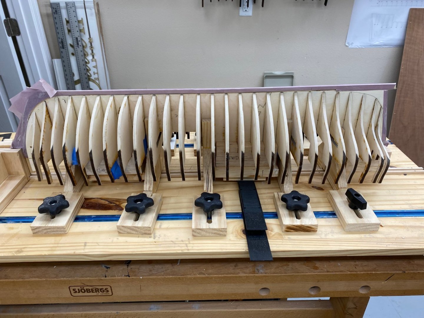
This may the last post for a few days as I have all the bulkheads installed and it is time for fairing the hull. Being a belt and suspenders kinda guy, after the Titebond was completely set I ran a bead of medium CA using a small paint brush down both sides of each seam just to make sure they were bonded together. I put masking tape over the keel and stem to (hopefully) keep them safe from marauding sanding blocks. I turned the model over and added some spacers to keep the bulkhead extensions off the build board. At least through the lower hull fairing this will be its position. When I get it to my liking I will turn it over, add the binder clips on the bulkhead extensions and fair the upper hull. I also moved the build board over to my woodworking bench where I can easily get access to both sides and the build board is clamped onto the bench so it won't move either.

- 389 replies
-
- 5
-
-
- winchelsea
- Syren Ship Model Company
- (and 1 more)
-
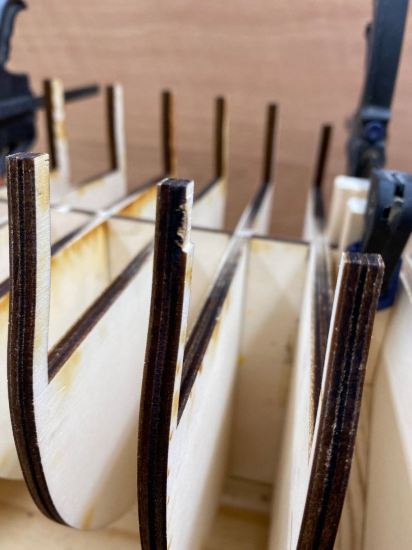
As I mentioned previously I had to complete the laser cuts on several of the bulkheads. In the process the bulkheads "shed" some pieces of the outer ply of the plywood in a few places. I probably should have "fixed" this before installing the offending bulkheads but... Anyway here is what the "ply loss" looks like. This is bulkhead M. I cut a short piece of 1/32" by 5/16" yellow cedar and am gluing it onto the bulkhead. I will have to trim it back to the bulkhead dimensions after it dries. And speaking of bulkheads - we are complete, including the bow fillers, just waiting for the last set of glue to dry. Tomorrow my new set of 1.5" binders clips are supposed to arrive so I will have to wait until they get here to start fairing. I am also planning on getting some of "L" brackets that Chuck shows in the instructions to support those really "tender" bulkhead extensions at the stern. The odd small clips are supporting additional ply layer repairs.


- 389 replies
-
- 6
-
-
- winchelsea
- Syren Ship Model Company
- (and 1 more)
-
Nine bulkheads in place - the six below and three at the bow (done before I started in the middle).
- 389 replies
-
- 8
-
-
- winchelsea
- Syren Ship Model Company
- (and 1 more)
-
Thanks Oldsalt, Plus I can do two bulkheads at once. I just did "S" so I will move to #3 and #5 and move from there. I will have to figure out some way to true up "O" since there will not be enough room to use any of the machinist blocks I have in the 3/4" wide space between bulkheads.
- 389 replies
-
- 1
-
-
- winchelsea
- Syren Ship Model Company
- (and 1 more)
-
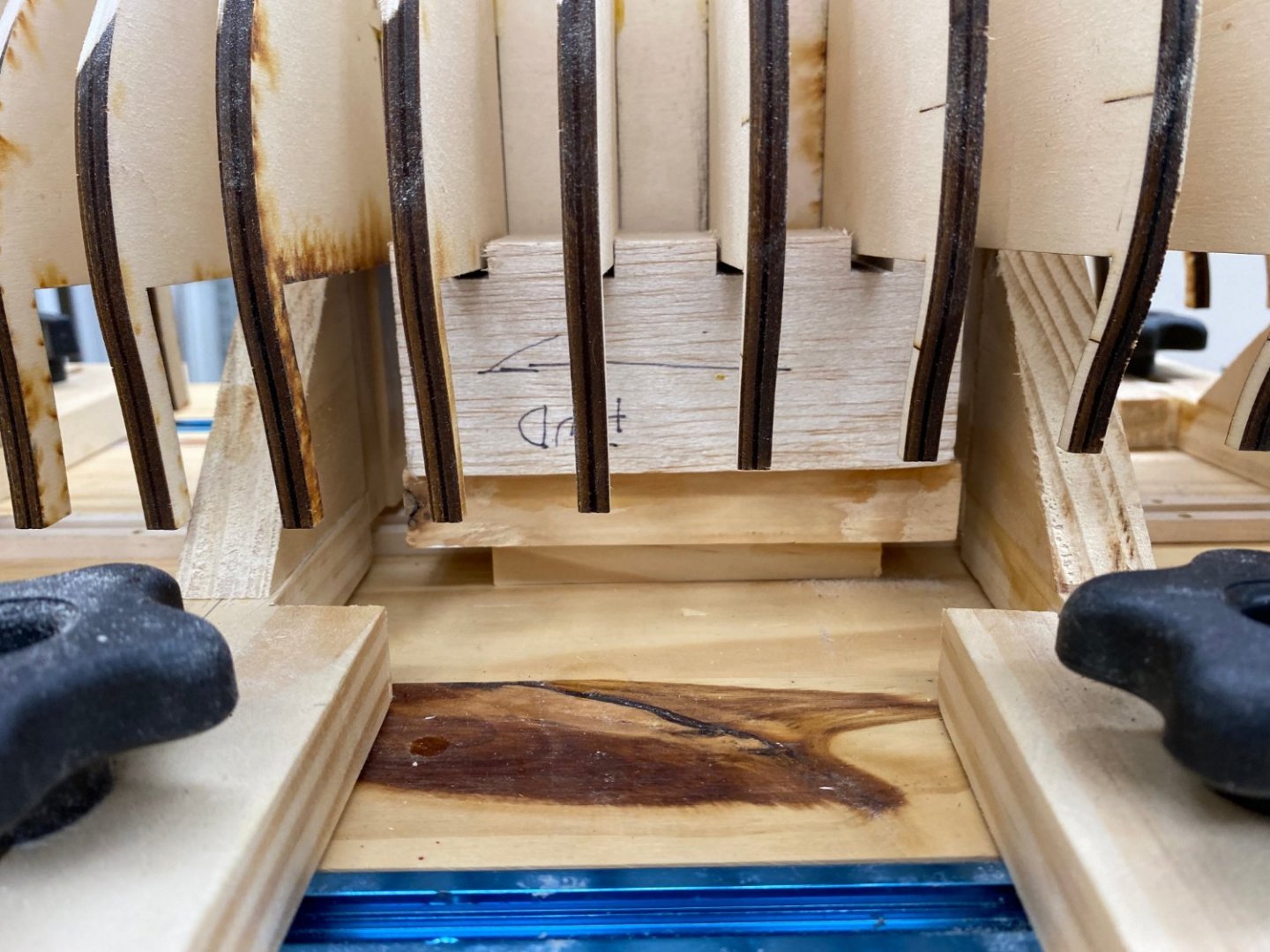
So I drilled two holes in the underside of the center keel assembly using the "big" drill press in the garage. I used a #32 drill which by my calculations and measurements should the correct pilot hole for a #6 wood screw. So with that done it is time to mount the center keel for serious bulkhead installation work. I had to widen the "tracks" that hold the keel on the center of the build board since this keel is just slightly wider than 1/4" even after sanding it to remove the laser char on the sides. I used all five of the vertical supports and put a C-clamp on top just to sure they have a good grip on the center keel. Here is how it looks with the first bulkhead dry fit- I started from the bow for no good reason. When I looked at the bottom of bulkhead W I found that it extended significantly over the rabbet joint. So I will have to trim the ends of this one before it gets glued in. Here is what I found. - Port side Starboard side So I trimmed the ends of the bulkhead back to clear the rabbet joint. Likely even more of this bulkhead will be faired away but I want to protect the stem from that process as much as I can so trimming this, at least this far, now makes good sense (IMHO). Here is the "corrected port side. And with that completed it is time for the glue. Here is bulkhead W (with the letter on the forward side as directed) "glued and trued"(hopefully.


- 389 replies
-
- 3
-
-
- winchelsea
- Syren Ship Model Company
- (and 1 more)