HOLIDAY DONATION DRIVE - SUPPORT MSW - DO YOUR PART TO KEEP THIS GREAT FORUM GOING!
×


cdrusn89
-
Posts
1,915 -
Joined
-
Last visited
Content Type
Profiles
Forums
Gallery
Events
Everything posted by cdrusn89
-
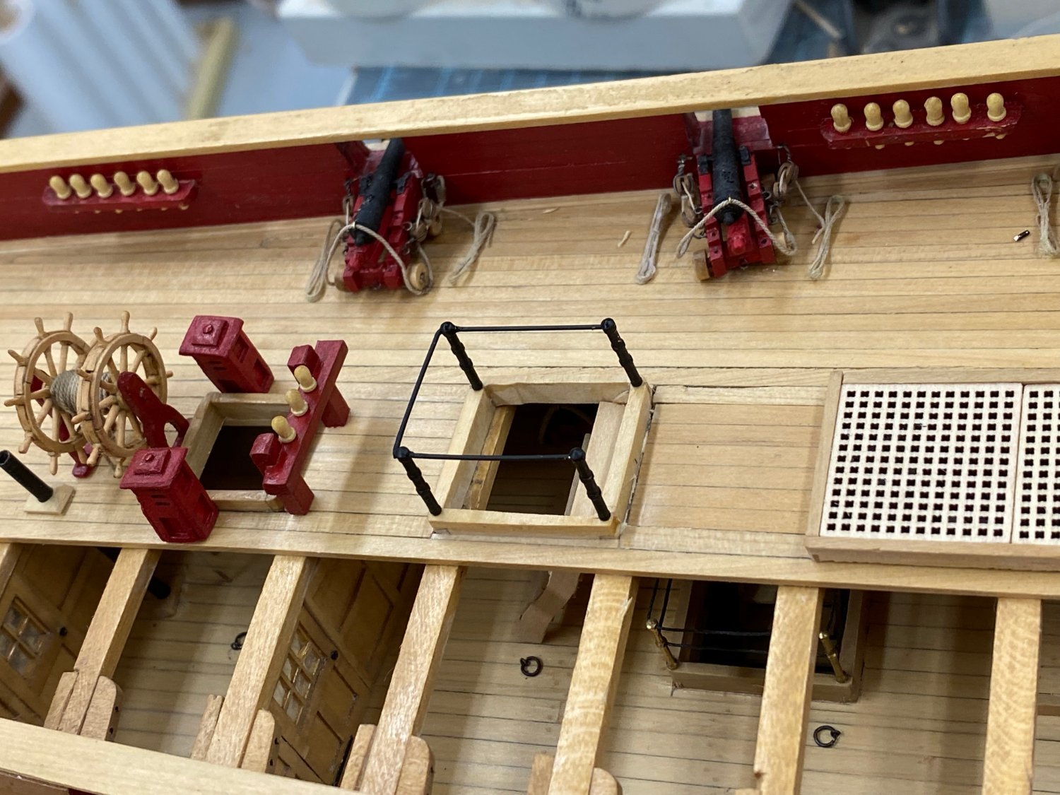
 Thanks Bruce. I actually did all the guns ahead also - then found out the ones I built (from Syren) were too big and got to do it all again. I am saving them for the Wenchelsea which I hope will be next. The final detail on the quarterdeck, the railing around the ladder leading below. I found some really nice looking railing stanchions I got somewhere a long time ago (I think from BlueJackets but ...). They are round (not flat like the photo etched ones) but are drilled for three rows of railings which might look like overkill for the period. Hopefully the extra holes will not detract from their appearance. Here is what they look like before painting. Unfortunately they only came drilled straight through (no special "corner" stanchions) so I had to run the railing "around" the corner. I thought about steel wire but even this short a length may be hard to get a straight piece and keep it straight while installing. So I used some .025" phosphor-bronze wire. It bends and cuts pretty easily (compared to piano wire) and I have plenty as I anticipated it might take several tries to get the bends exactly where they need to be. Anyway here it the quarterdeck in all its glory. Including a few spare pieces of flotsam since removed.
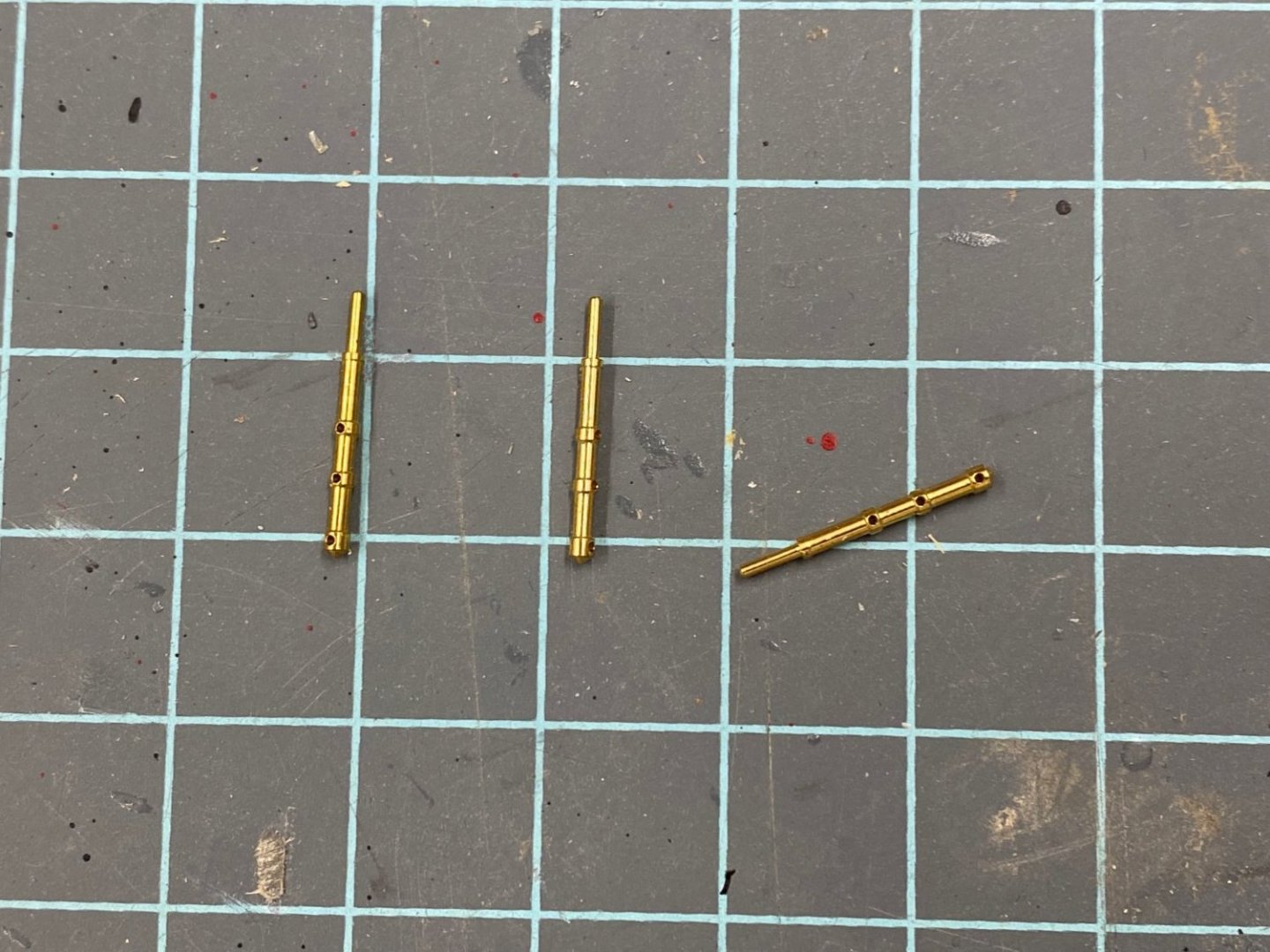

- 370 replies
-
- 4
-

-
- Model Shipways
- Confederacy
- (and 1 more)
-
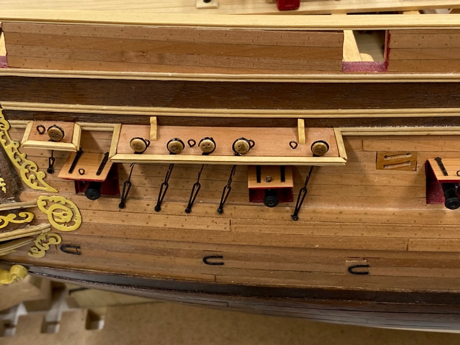
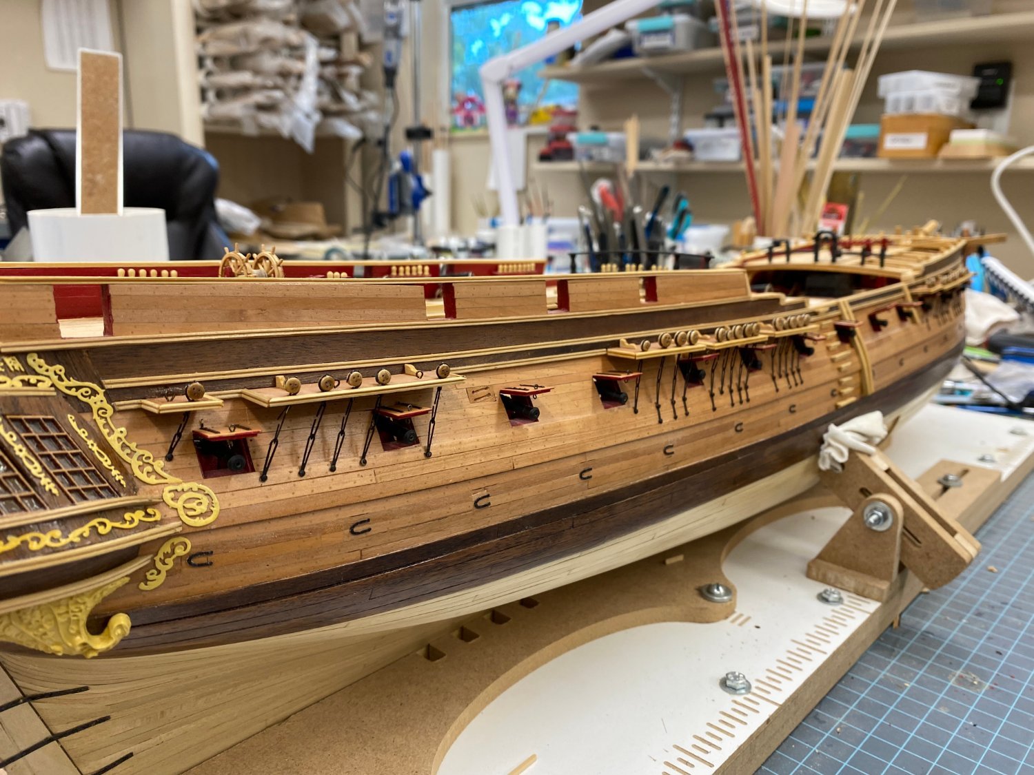
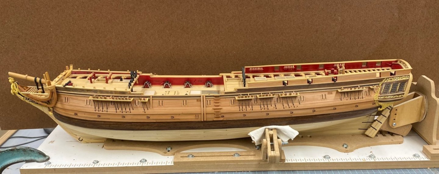
Port side chainplates complete - getting close to "THE END" of this project. There are only three relevant pagers left in the instructions (I already built the anchors and ship's boats). On to the various railings and the gangways. I thought about only putting the gangway on one side but then I could not figure out an "elegant" way of holding up the boat skids on the side with no gangway so I will install both.
- 370 replies
-
- 4
-
-
- Model Shipways
- Confederacy
- (and 1 more)
-
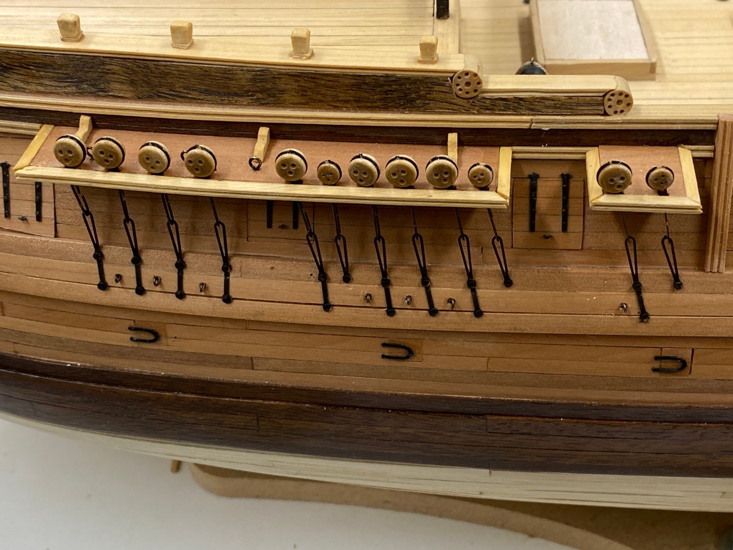
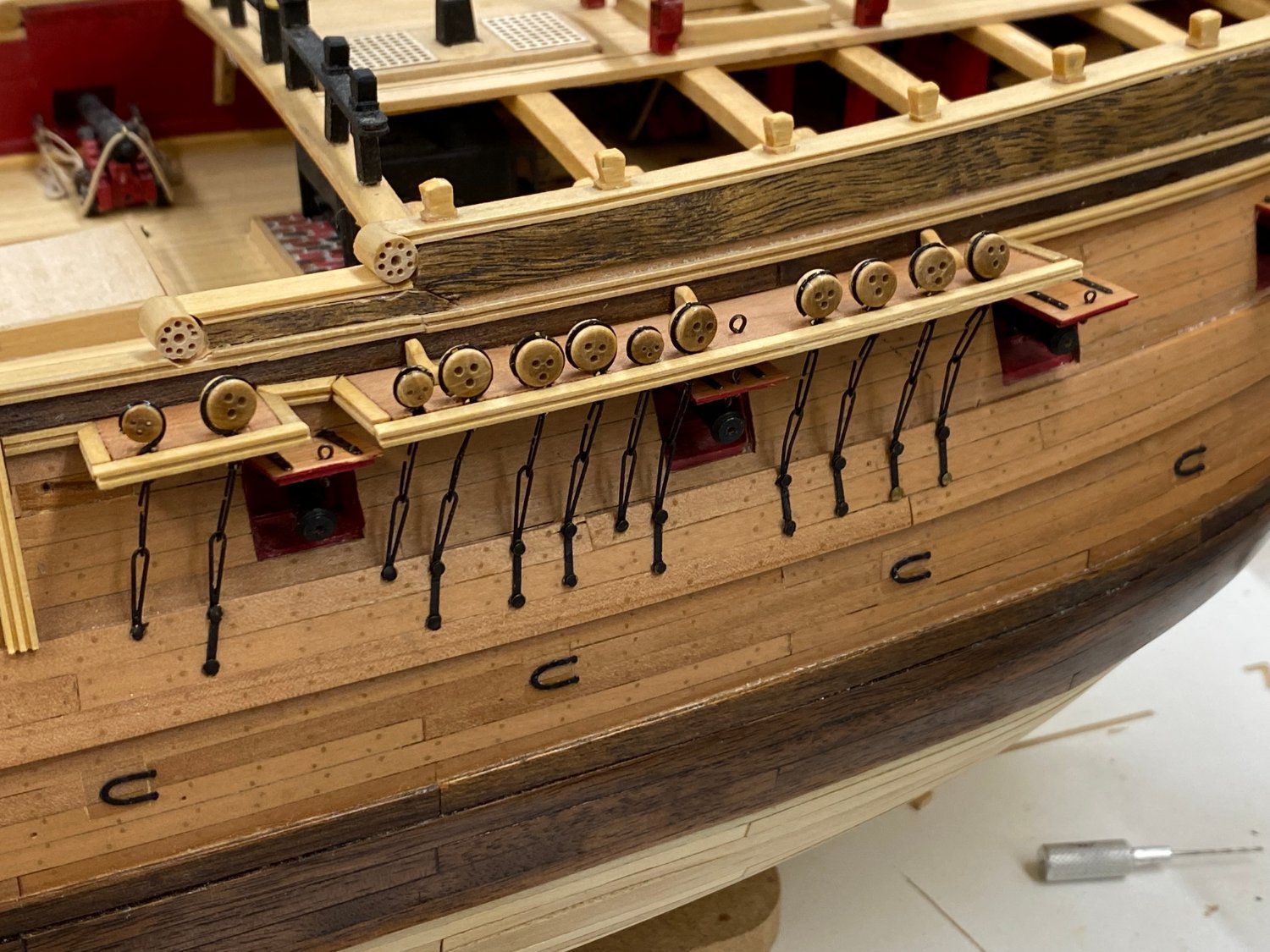
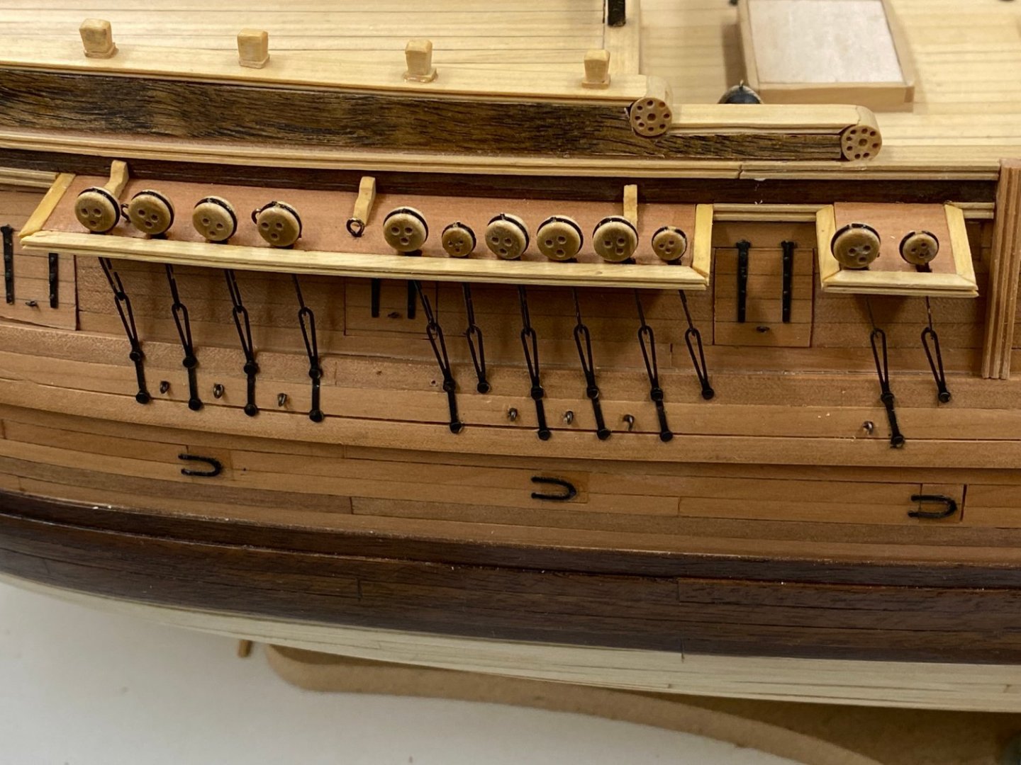
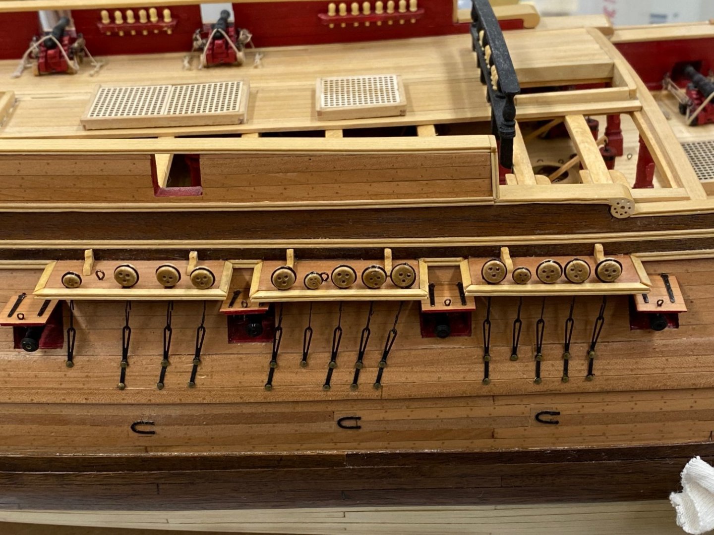
Port side Fore mast chainplates completed. And this time I remembered to put the eyebolts between the preventer plates. I am not sure what these were/would be used for but they are on the plans and mentioned in the instructions sooooo. Unlike the starboard side on this side I remembered to narrow the channels on each side to account for the additional molding piece on each side. I forgot about that "detail" on the starboard side. but am not about to tear it all out and start over. Besides, I probably do not have enough spares of the photo etched chainplates to do another set.
- 370 replies
-
- 1
-
-
- Model Shipways
- Confederacy
- (and 1 more)
-
Main chainplates done. Mizzen is almost done, then on to the port side.
- 370 replies
-
- 1
-
-
- Model Shipways
- Confederacy
- (and 1 more)
-
He's back! From a month long trip to Europe. So I better get to work. We leave again on 6/29. I have struggled since I started this build with what to do about the chainplates. I was not crazy about the photo etched brass that came with the kit, since they are not round and look pretty easy to "mis-handle" so I ordered samples of some of the chainplates that are available commercially. However, I could not find anything that is close to the arrangement shown on the plans and most of what is available would seem to be out of scale compared to what is provided with the kit. So I have decided to use the kit provided materials. I have all the channels installed on the starboard side along with the eyebolts. I have completed the chainplates for the fore mast channels and here they are. The "trim pieces" around the channels are not is "nice" looking as I had hoped but it is too late to try something else so I hope it grows on me. Also getting the bottom of each chainplate to end at the same place is somewhat of a challenge, even with the multiple lengths of one of the links provided.

- 370 replies
-
- 3
-
-
- Model Shipways
- Confederacy
- (and 1 more)
-
This is probably my last post for awhile. I am leaving on a month long trip overseas tomorrow at some point. It will be Memorial Day weekend when I get back so next post will probably be in early June. Keep up the good work everyone.
- 370 replies
-
- 2
-
-
- Model Shipways
- Confederacy
- (and 1 more)
-
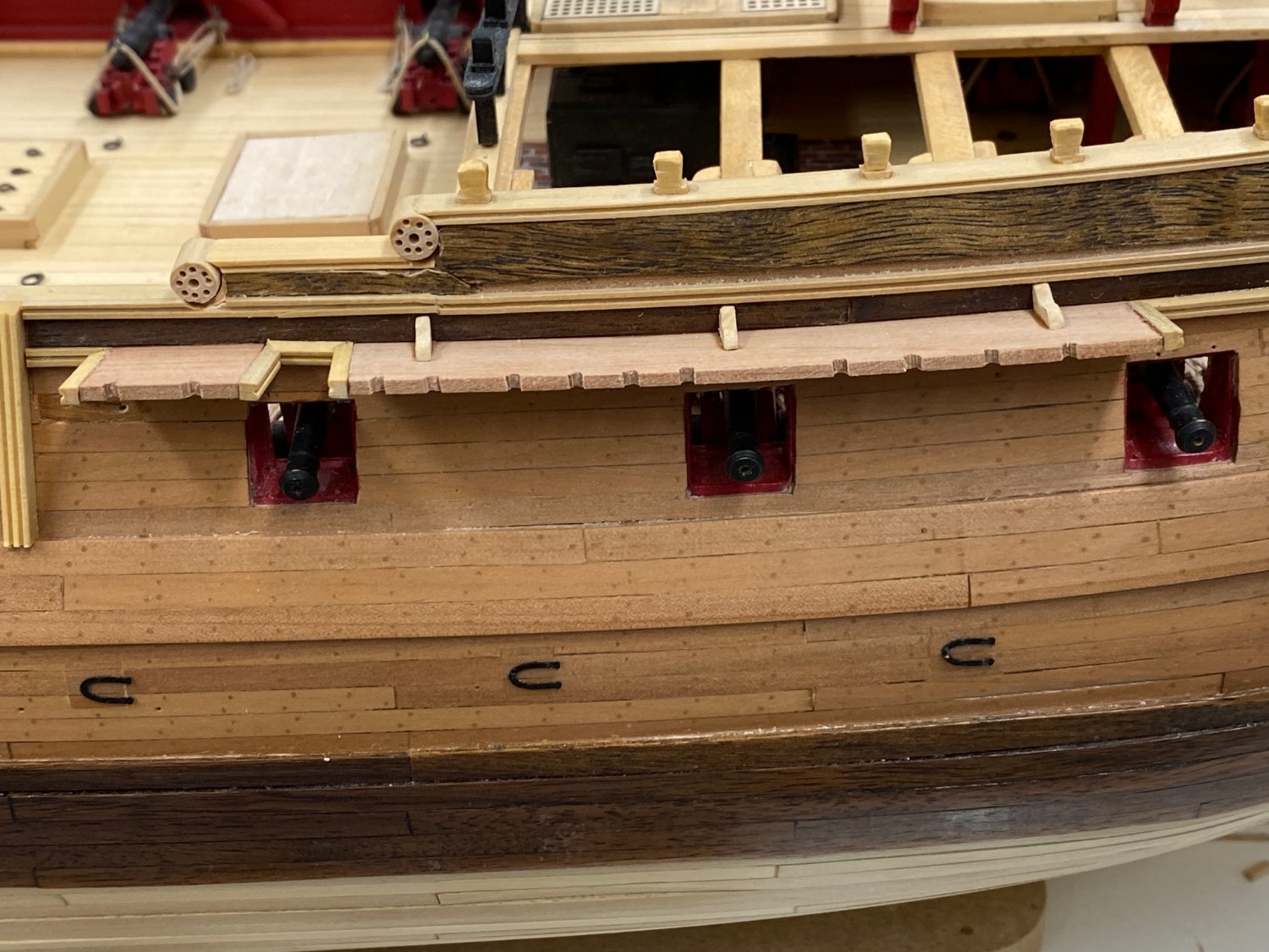
On to the channels now that the gun port doors are "done". The instructions recommend extending the molding strips around the channels by using the provided scrapers to do the ends of the channel,platforms. I decided to do the channels in Swiss pear so scraping the ends of the channel platforms does not really match the instructions intent. So, I decided to add the boxwood molding on the ends of the channel, platforms. The same molding (in boxwood) will cover the outer edge of the channels once the deadeyes and hardware are installed. thus the model will have a more or less continuous boxwood molding strip at the channel level to match to one on the follows the main rail at the gun deck level. I also decided to fab the standards (inverted knees) in boxwood rather than Swiss pear in keeping with my plan of having the detail in boxwood. I made enough for both sides but may reconsider the port side since I did the boarding ladder and fenders in Swiss pear on that side. Here are the forward, starboard channels, molding and standards in place but no WoP yet.

- 370 replies
-
- 4
-
-
- Model Shipways
- Confederacy
- (and 1 more)
-
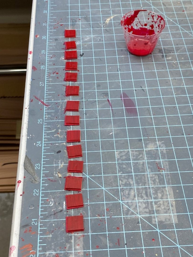
On to the starboard side gun port doors. The port side was done some time ago as I am showing them closed. Luckily I made up plenty of "stock" from which to make the doors so it was just a matter of cutting them to size and matching the plank pattern - not that it will be noticeable with the open doors but... I used the Byrnes table saw and a .040" kerf blade to make the rabbet around the sides but only did three sides. I left the side that faces the hull the full width. I have my doubts about the ability of the sprue to support the door so I think having a full 1/16" bearing surface against the hull might be prudent. And it is not like the absence of the rabbet at the back of the door is going to be noticeable. So here are the 14 doors ready for adding the eyebolts and hinges. And here they are after the details have been added. I just touched up the edges with red paint. Next I will sand to get the "extra" paint off the outside and then add a coat of WoP. The "stock" was already WoPed so (hopefully) the red paint is not soaking into the outside of the doors.
- 370 replies
-
- 3
-
-
- Model Shipways
- Confederacy
- (and 1 more)
-
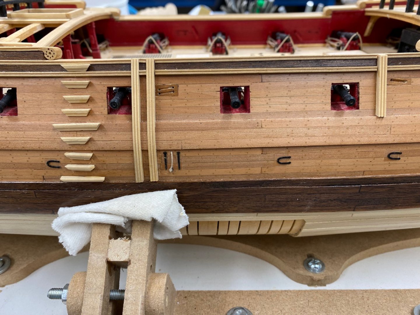
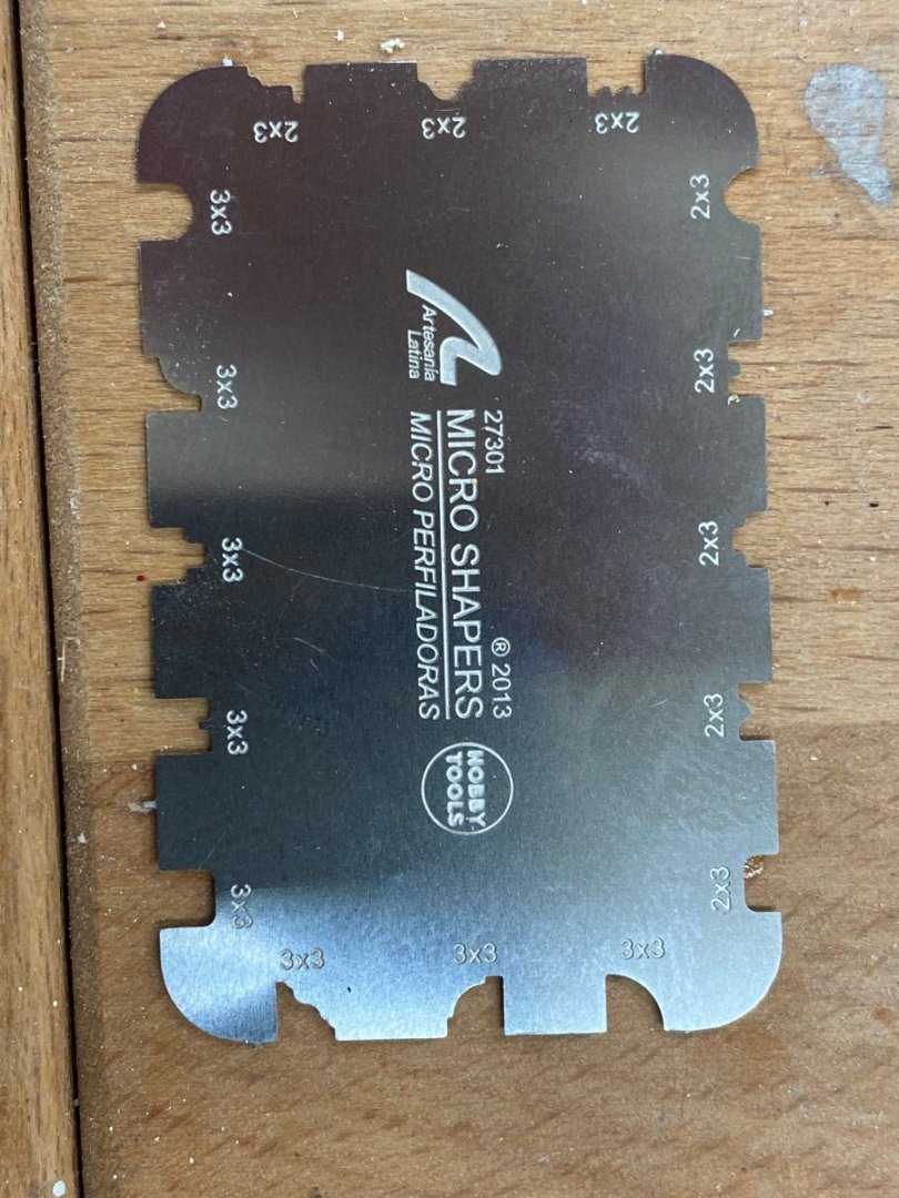
Starboard side boarding ladder and fenders in place but not yet WoPed. I decided to make these items in boxwood instead of Swiss Pear so they would standout like the other "trim" items, at least on this side. I may do the other in Swiss Pear just to be different. The boxwood is much easier to fashion using moulding cutters than the pear. And don't ask about walnut, at least the walnut I have is very "grainy" and not suitable at all (IMHO) to being shaped with a cutter. Here is the starboard side. I used the Artesania Latina cutters shown below. I used the 3X3 cutter on the bottom left for the boarding steps and the 2X3 one on the top right for the fenders. I used the thickness sander to thin down some 1/8" X 1/8" boxwood to either 3X3 or 2X3 mm to fit the cutters.
- 370 replies
-
- 2
-
-
- Model Shipways
- Confederacy
- (and 1 more)
-
I finished the fab of the boomkins and the false rails in boxwood. I glued in the false rails and the boomkins are just sitting in approximately the correct position. As I said before I am going to defer installing the boomkins until the end of the build to keep my elbows (or other appendages) from tearing them off during the remaining construction.

- 370 replies
-
- 6
-
-
- Model Shipways
- Confederacy
- (and 1 more)
-
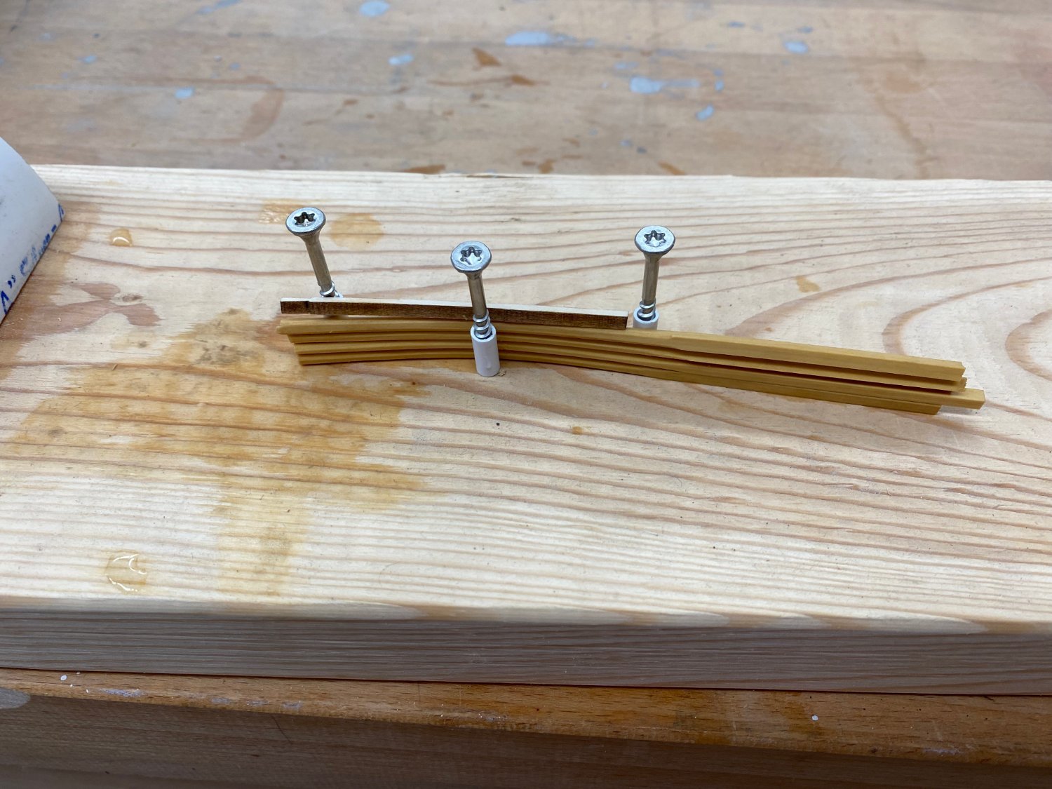
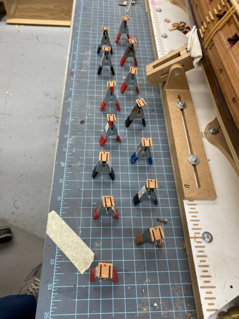
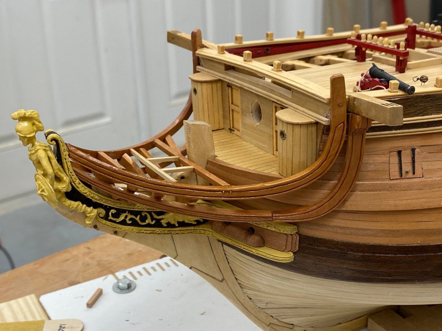
I fabbed the knightsheads from Boxwood previously and had to add a 1/16" "filler" to the bottom to get the profile to match the bowsprit. I could have redone them but I am out of boxwood in 1/8" wide enough to do so instead of thinning out some other piece I took the path of least resistance and added the filler. Here is the bow with the knightsheads installed. I need another coat of WoP but will wait for the boomkins. Speaking of Boomkins, I am thinking that waiting to install them might be the right move. I am nervous of having things sticking out from the hull at this point since there is still a good bit of work that needs to be done; not necessarily at the bow but elbows being what they are I still think waiting until the "last moment" to install these in probably a good idea. I am going to fab the boomkins from boxwood so I cut some 6" lengths of 1/8" X 1/8" boxwood and sanded them to eight sided then soaked them in water and put them in a jig to bend them to approximately the required shape. Here are four pieces (just to be on the safe side) and the laser cut piece from the kit on the jig drying.


- 370 replies
-
- 5
-
-
- Model Shipways
- Confederacy
- (and 1 more)
-
Glue is dry and gammoning is complete. I would suggest that the seats of ease abreast of the bowsprit not be installed until the gammoning is completed. Don't ask how I know this would be better.


- 370 replies
-
- 3
-
-
- Model Shipways
- Confederacy
- (and 1 more)
-
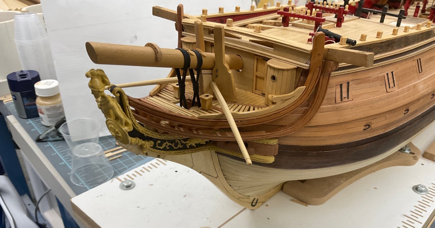
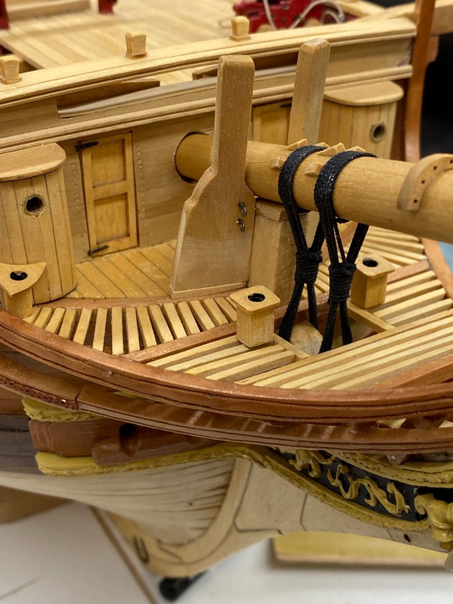
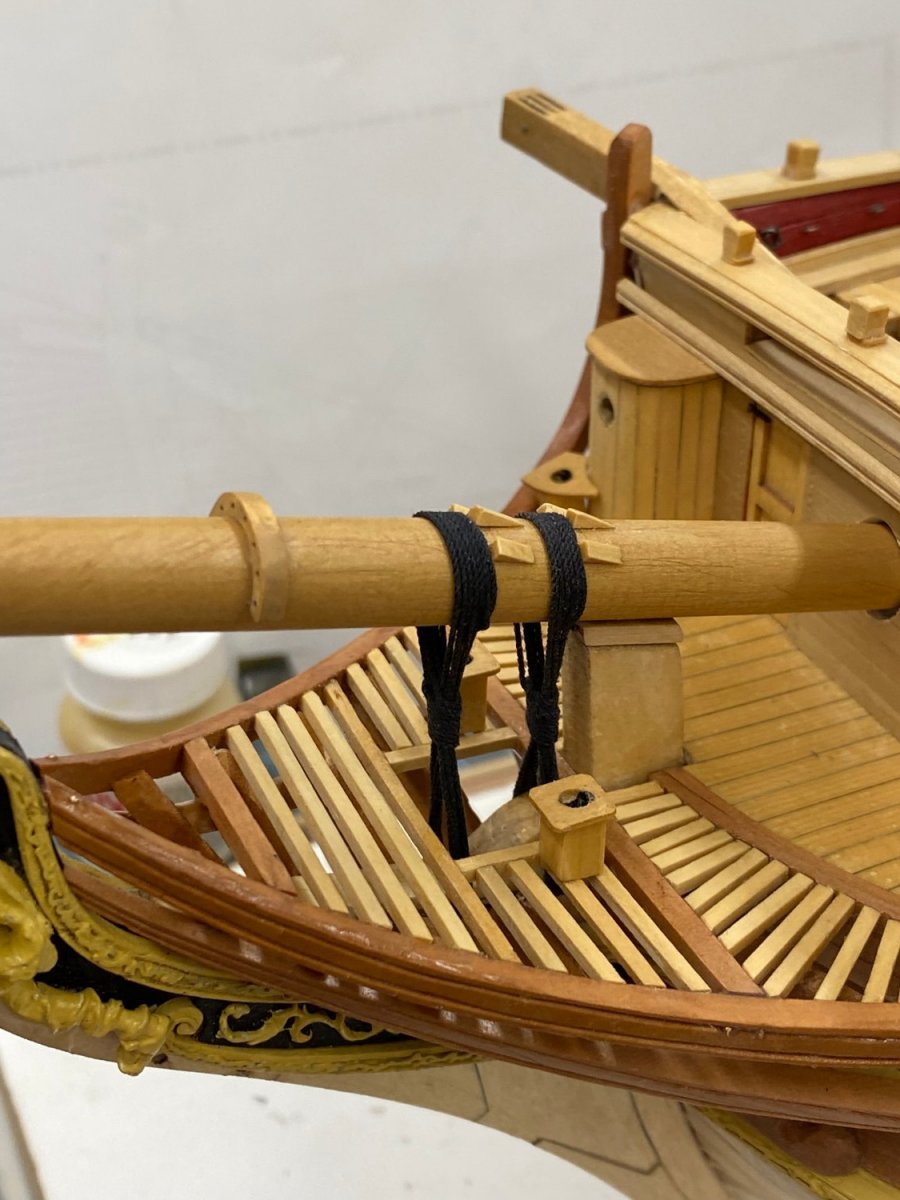
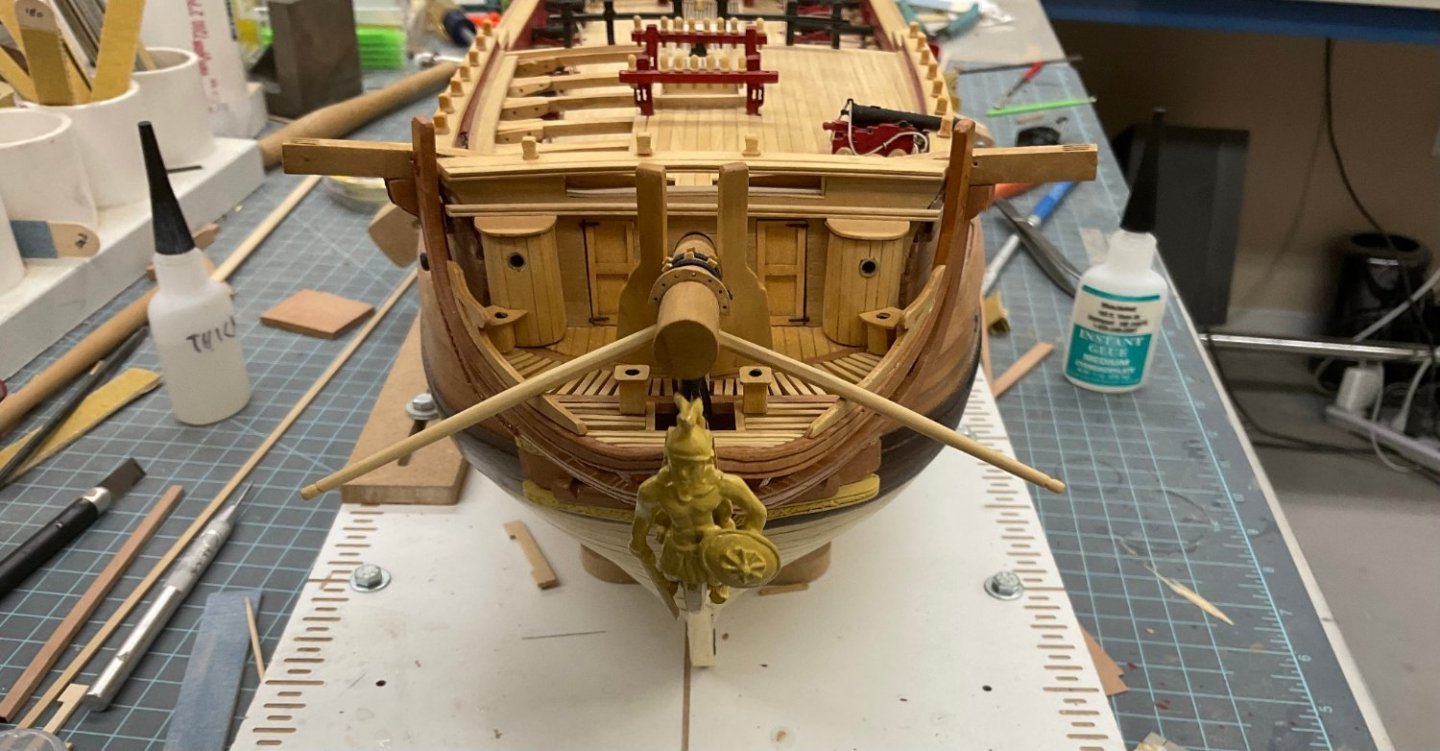
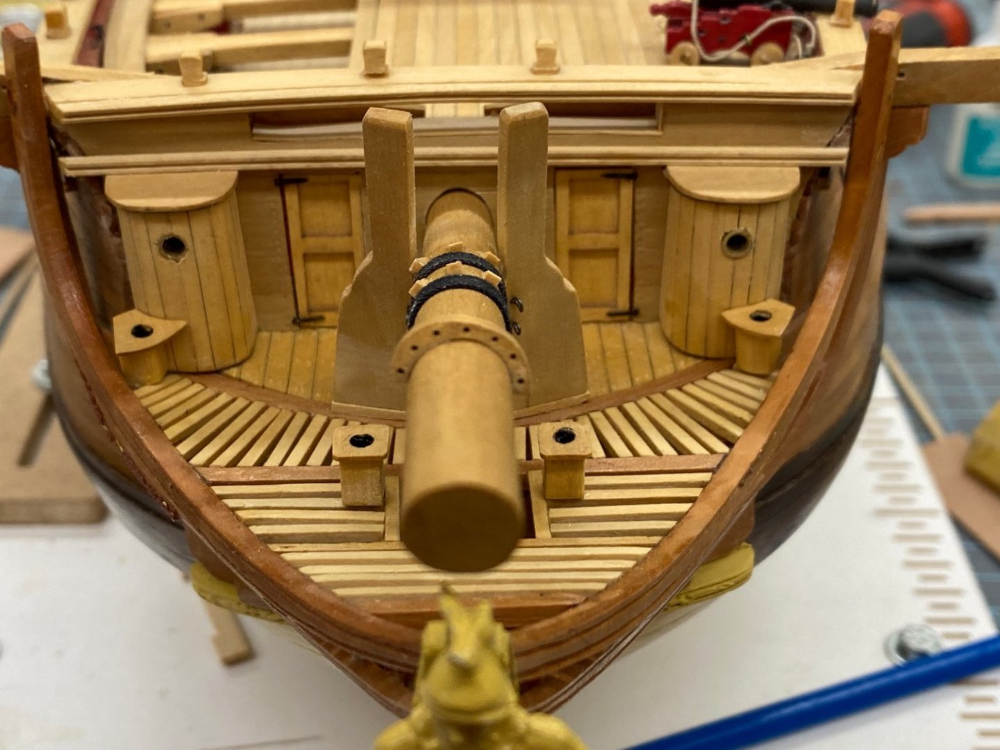
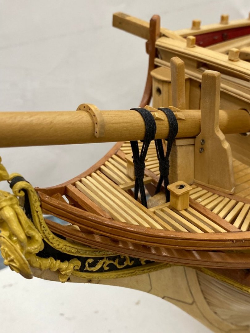
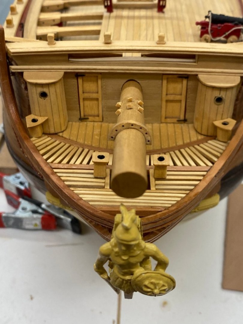
WoP is dry and I glued the seats of ease in place. I dry fit the bowsprit and despite messing around with the tendon I still needed a 1/16" block on top of the stem to keep the bowsprit from sitting DIRECTLY on top of the figurehead. Too late to do much else (IMHO) And here is the bowsprit - waiting for glue to dry before I try the gammoning.

- 370 replies
-
- 4
-
-
- Model Shipways
- Confederacy
- (and 1 more)
-
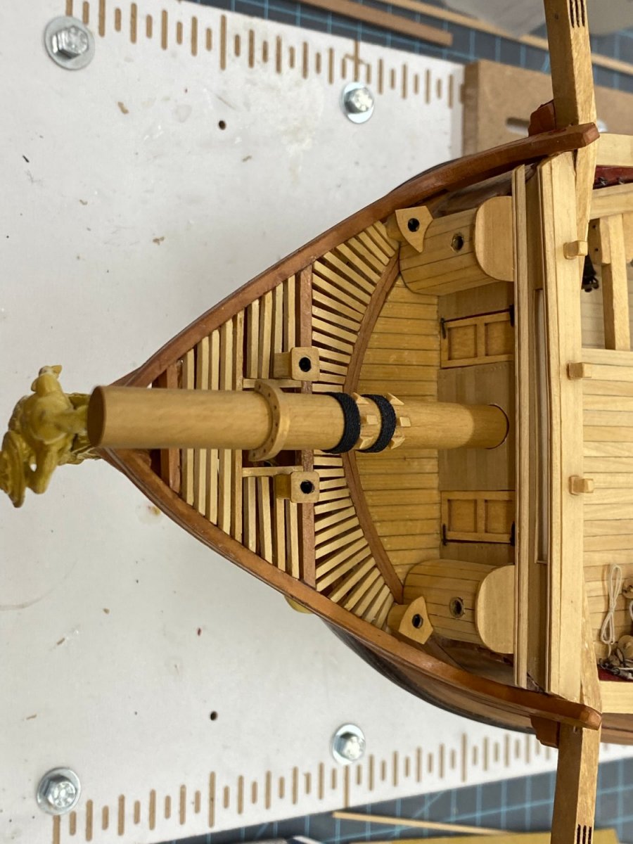
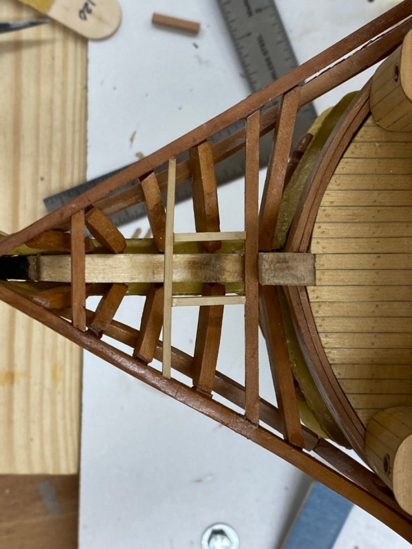
The uploaded image was right side (aft at bottom) up. I do n ot know why the site wants to turen it around. Anyway, the head grating is done, finally. I followed the plans from the forward most cross timber back to the start of the gammoning opening, i.e. five cross timbers between those two. I continued using the same spacing 9more or less) continuing toward the timber at the front of the stem but only have four timbers instead of the six shown in the plans. It is hard to tell from the pictures in the instruction manual whether there is supposed to be a change in spacing because that is not obvious in the plans. I would not want to have done the head gratings using this thin basswood. The boxwood at 1/16" X 1/16" was still pretty flexible and it took a good deal of care to not unintentionally bend one piece trying to get it to fit. It took several (maybe many) tries to get the piece to fit without bending it or what it was bearing against. Plus there were several occasions where a glue joint failed on the perpendicular piece while trying to fit in one of the gratings. Anyway, it is done, a final sanding a WoP next then on to the seats of ease and the bowsprit.
- 370 replies
-
- 4
-
-
- Model Shipways
- Confederacy
- (and 1 more)
-
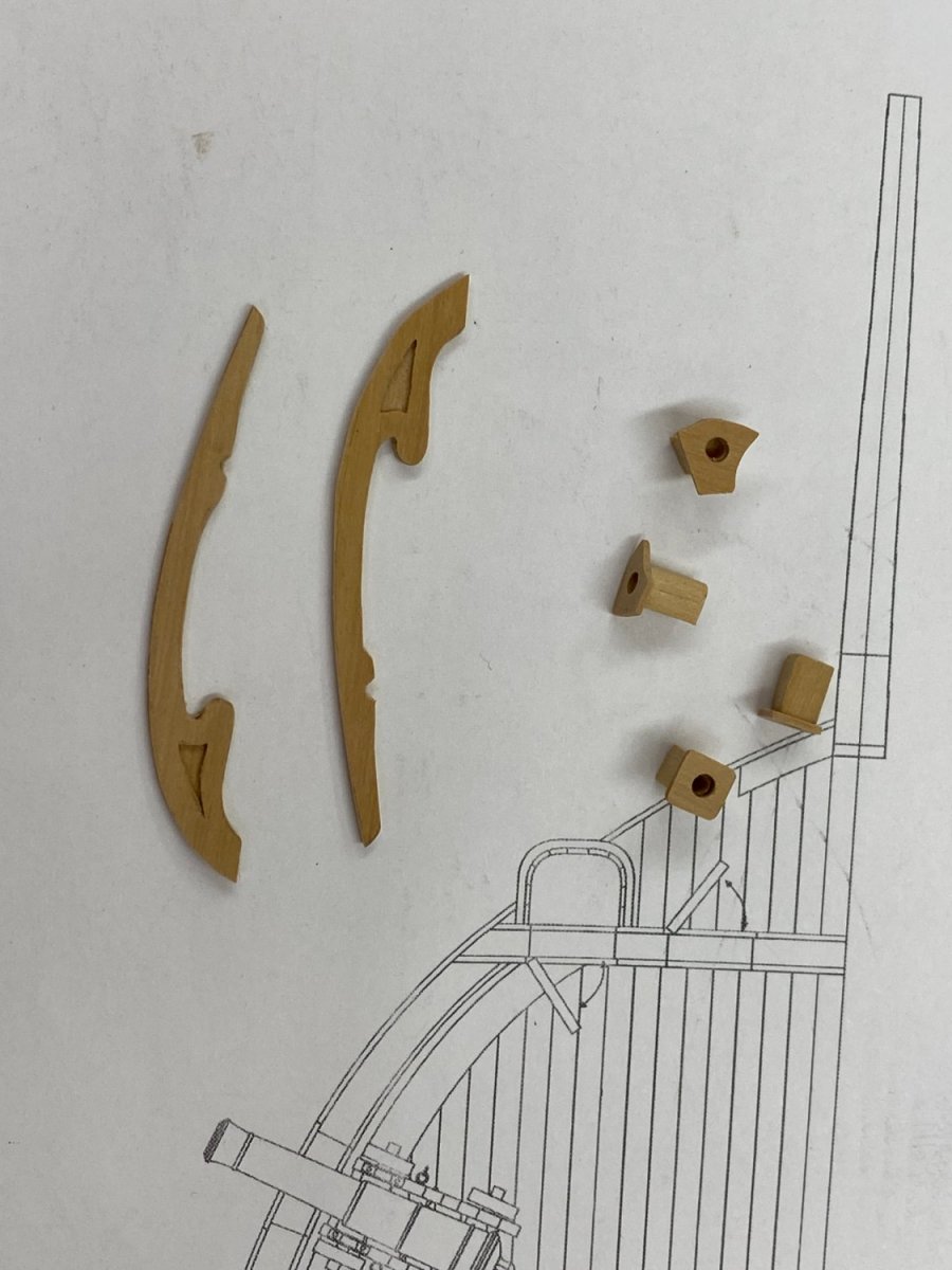
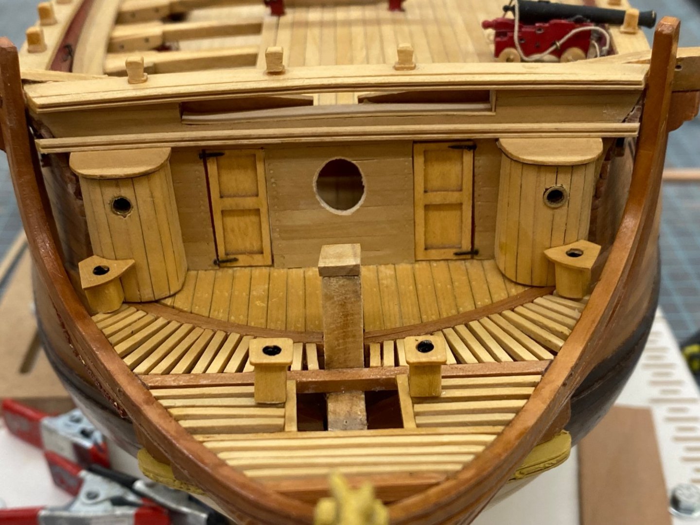
To take a break from the tremendous fun of adding the head gratings (NOT) I fabricated the "seats of ease" and the false rails from boxwood. The seats were relatively easy except trying to get trhe hole in the exact center of the 3/16" X 3/16" base. I decided to drill the hole in the seat before try to shape them, especially the ones by the round house. Boxwood is not as temperamental as basswood in thin sheets but it pays to make thing like holes (especially relatively large ones) away from the edges of the sheet. The false rails were somewhat more of a challenge and again it takes a bit of planning on how you cut the shape to avoid cutting along the grain and then trying to curve across the grain, better to cut, at least partially ,the curve across the grain before cutting along the grain. Here at the seats of ease and false rails after fabrication. They will get a final 320 grit sanding and WoP before installation. Since I had the grating on the starboard side completed I decided to see how they will look. Not sure yet how to "disguise" that the false rail in made of two pieces. Instructions suggest painting to look like wood but I am not inclined to follow that. Even filler will be pretty obvious. I think maybe nothing is the path I am on.


- 370 replies
-
- 4
-
-
- Model Shipways
- Confederacy
- (and 1 more)
-
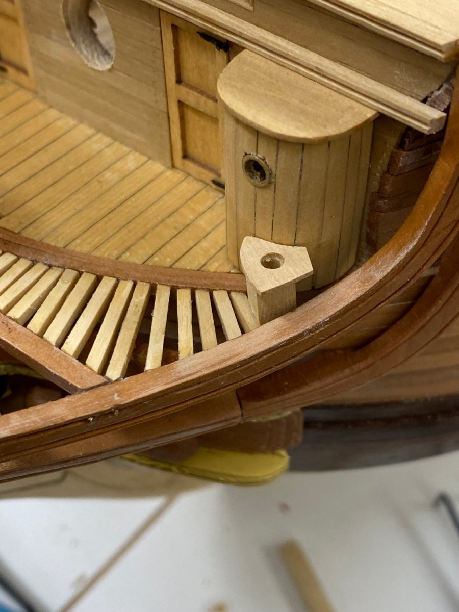
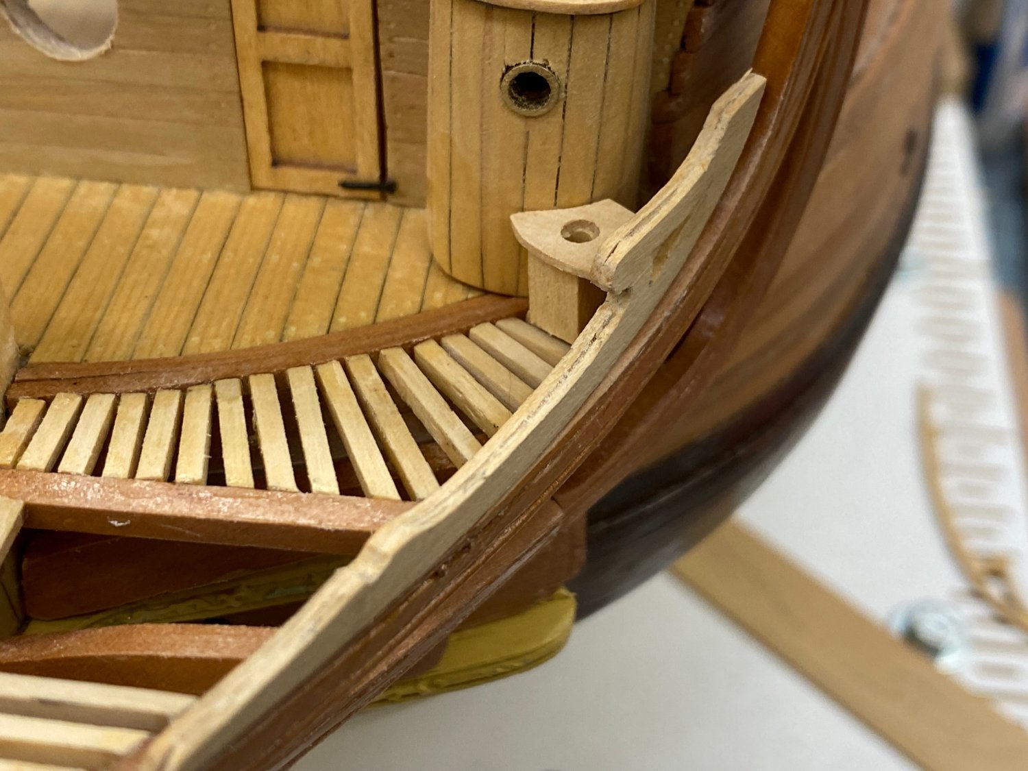
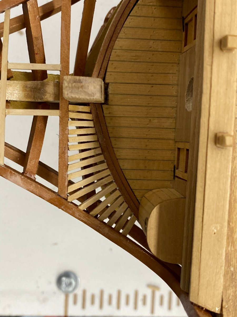
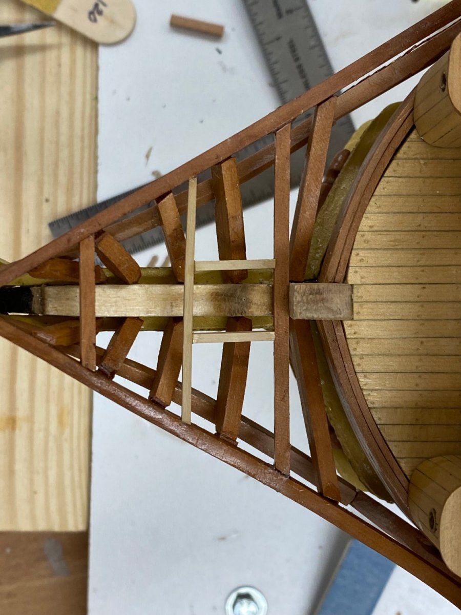
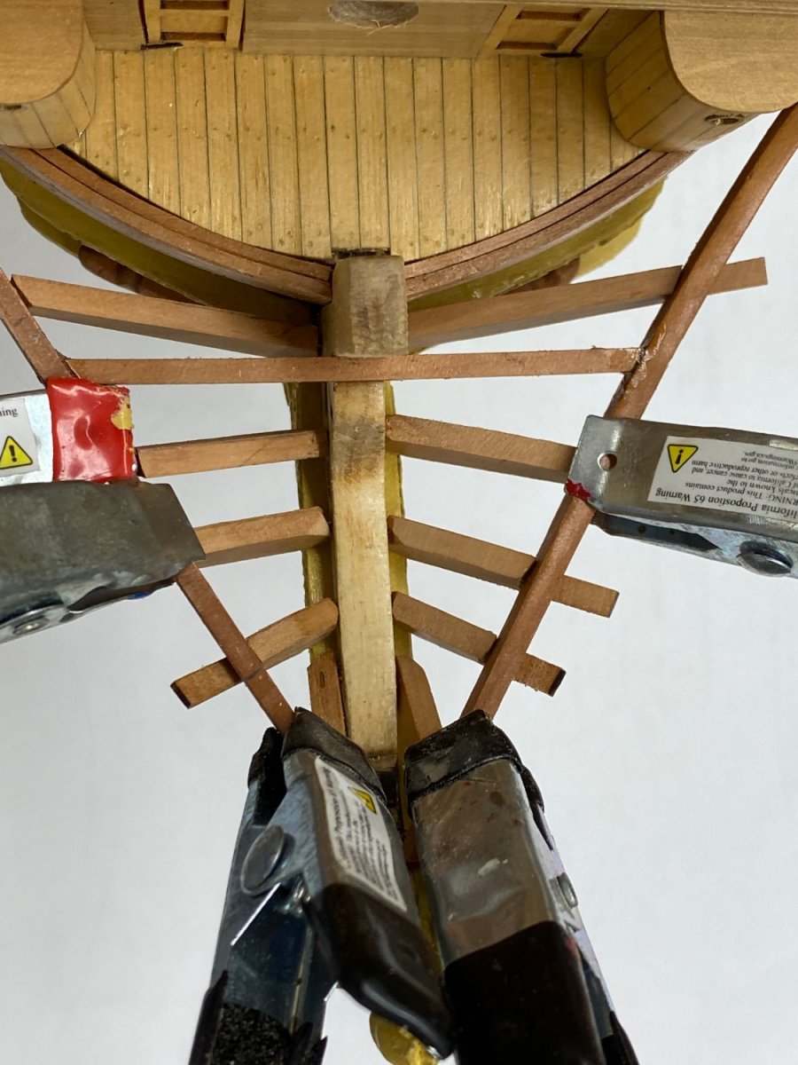
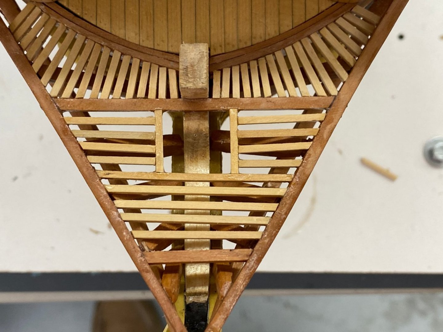
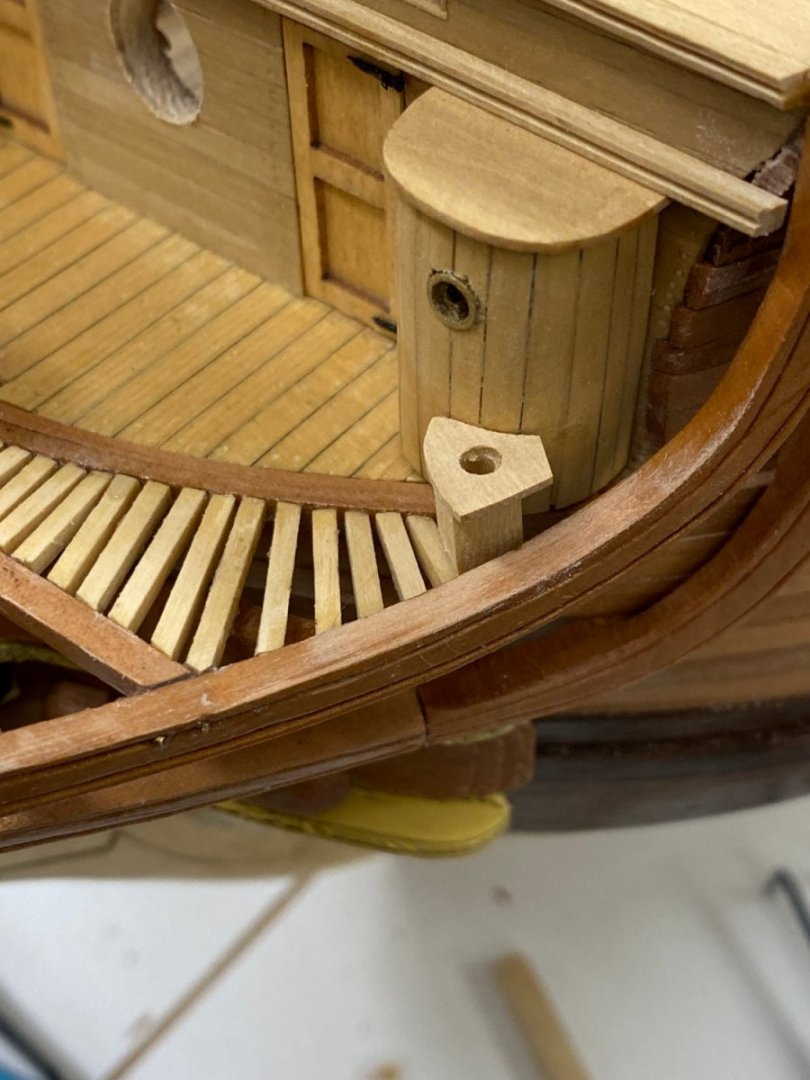
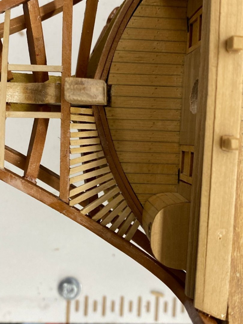
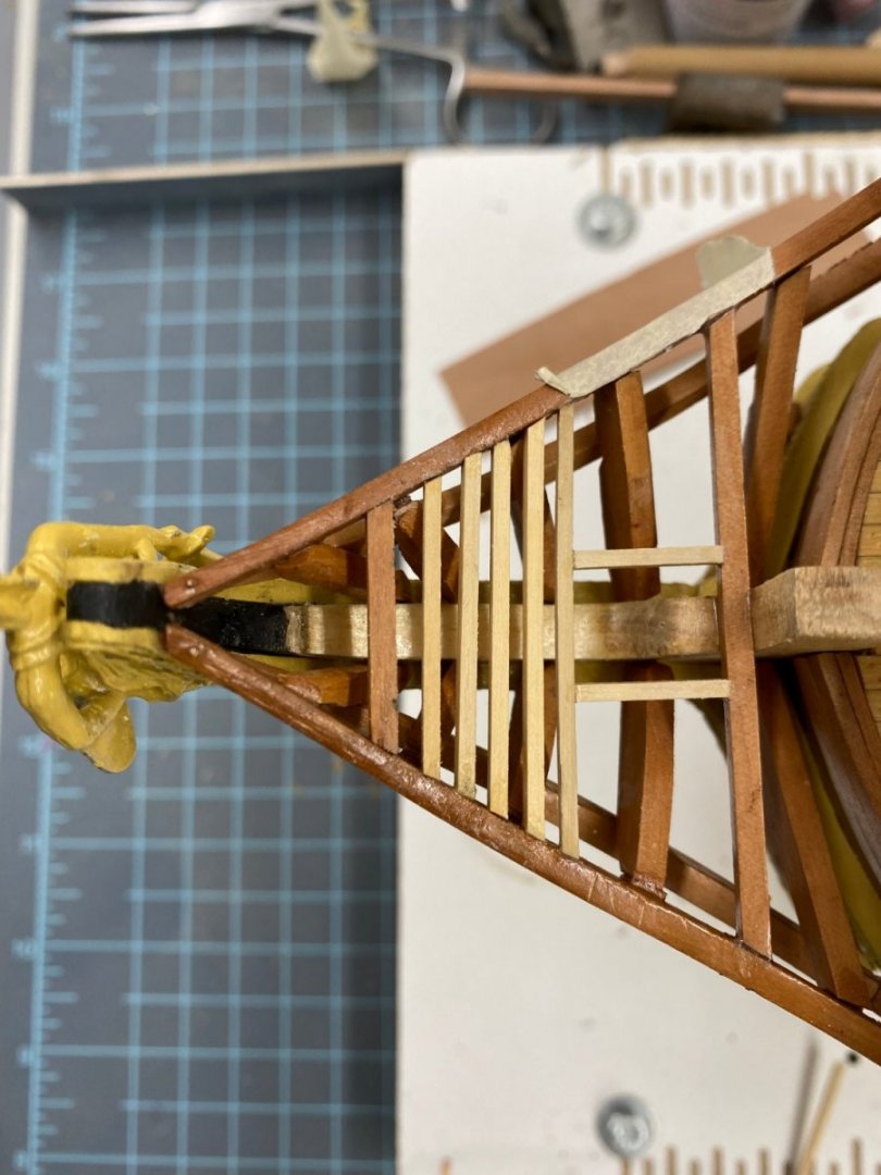
After I got the "slats" to port of the "corner" I took the rod out and glued another to support the starboard side of this section. There should not be a problem with determining that the slats are level with the beakhead deck since (in theory) the head rail is level with the beakhead deck here. For those who may build this kit in the future - work from the edges inboard rather than from the center out. It took me 20 minutes to get the piece next to the stem in place. It is really short and I had to use tweezers with long points to test fit the piece (probably a dozen times). I probably had 3 or 4 of them go flying (somewhere, I will find them some day) because of the thin grip of the tweezers. But, I did get the port side area completed. Not the most even and "fan-like" but with all the other stuff above the gratings it will be hard to notice the inconsistencies (at least that is what I am telling myself). I did manage to get 17 pieces just like the plans show so I guess I got at least that part correct. No to try and do the same on the starboard side.
- 370 replies
-
- 4
-
-
- Model Shipways
- Confederacy
- (and 1 more)
-
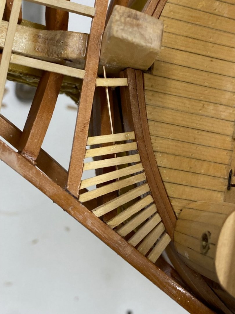
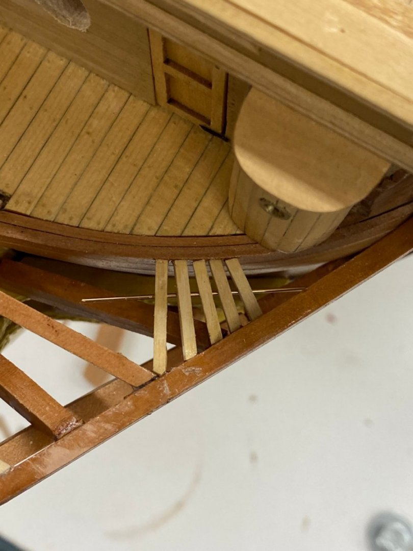
Working the head gratings - still. I got tired of losing the grip on the small pieces of 1/16" X 1/16" material and having them fall through while keeping the aft end of the pieces level with the beakhead deck did not look too difficult. But keeping them level looked like a challenge since the head rail is rising as you proceed aft. To provide some reference for "level", after I got the corner piece and the next one aft installed I glued (thin CA) a piece of .025" phosphor bronze rod to the bottom of these pieces to try and have a way of locating the forward end since the head rail is not going to be any help. Here are the first five pieces and you can see the wire helping to locate the forward end. The plans show 7 pieces so I need two more - they are going to be "really" short.
- 370 replies
-
- 2
-
-
- Model Shipways
- Confederacy
- (and 1 more)
-
More head gratings in place. I haven't decided yet about the framing for the "seats of ease" since you can't see them and handling those little pieces is a real challenge (for me). I am going to try the framing between the beakshead deck and the head rail - plans show 17 pieces on each side. Much fun anticipated.
- 370 replies
-
- 4
-
-
- Model Shipways
- Confederacy
- (and 1 more)
-
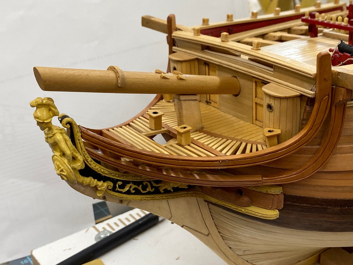
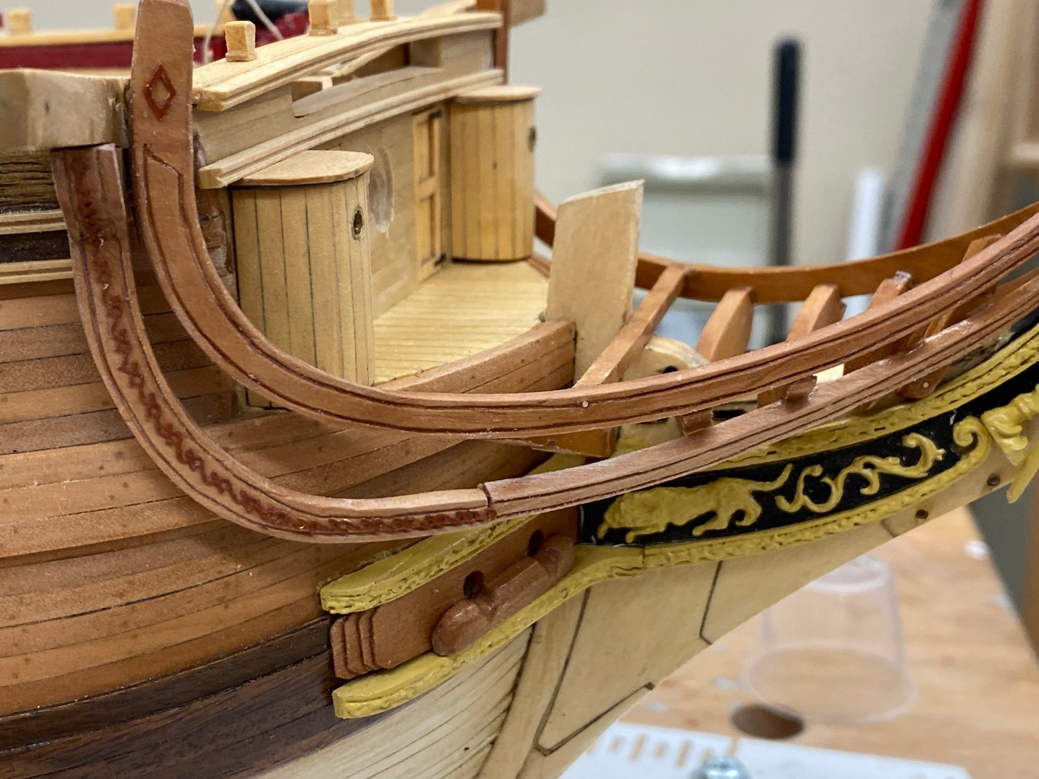
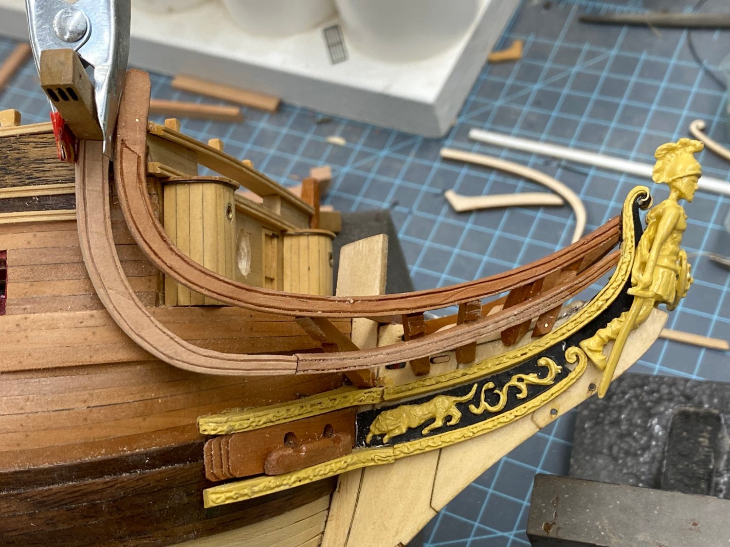
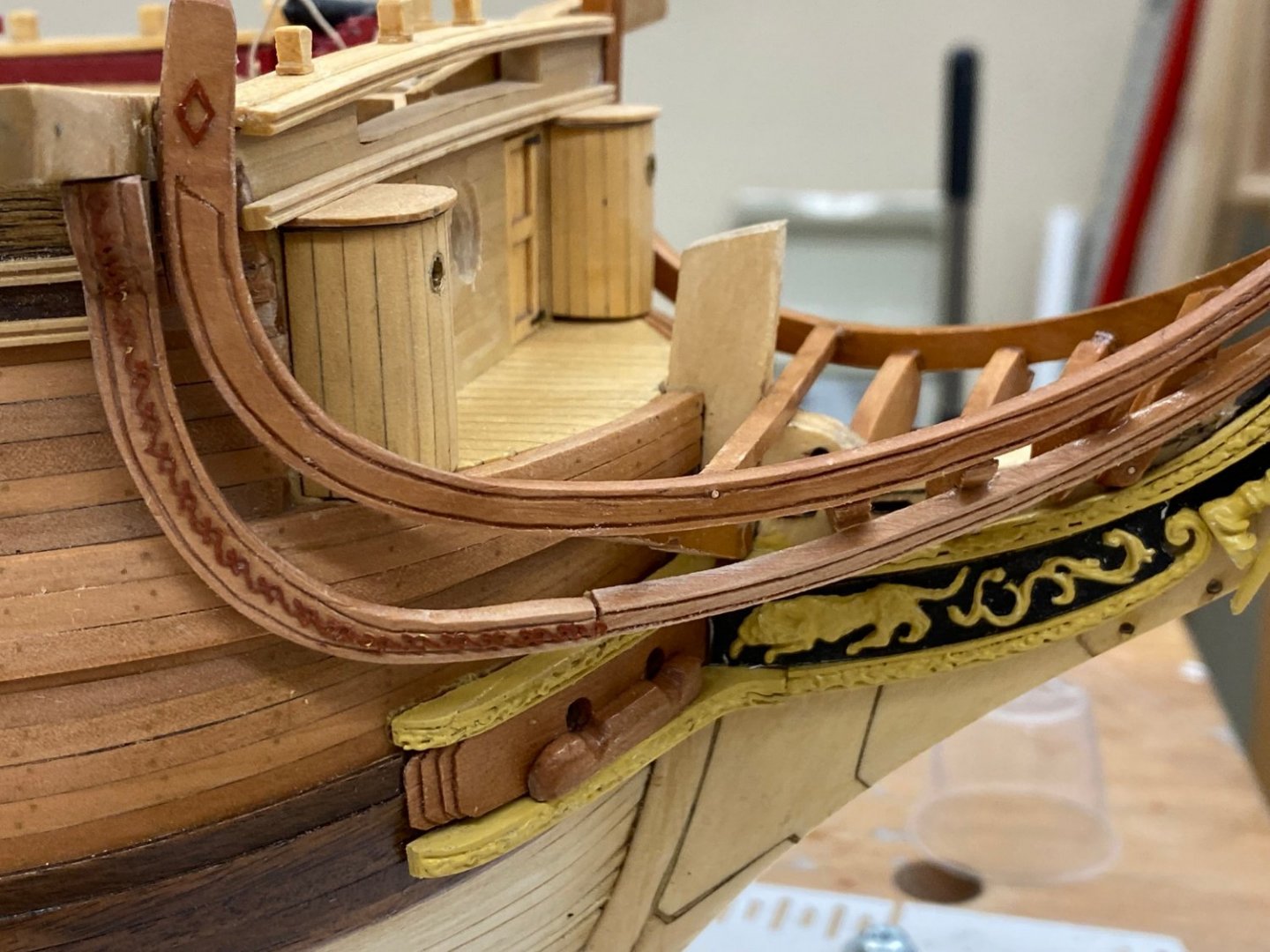
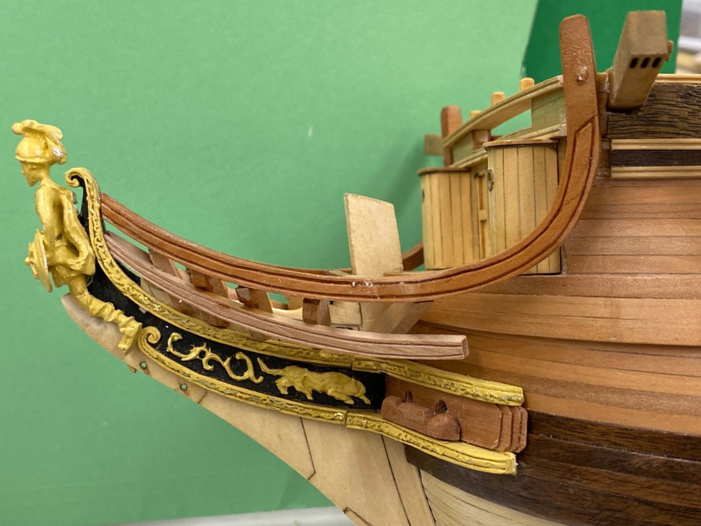
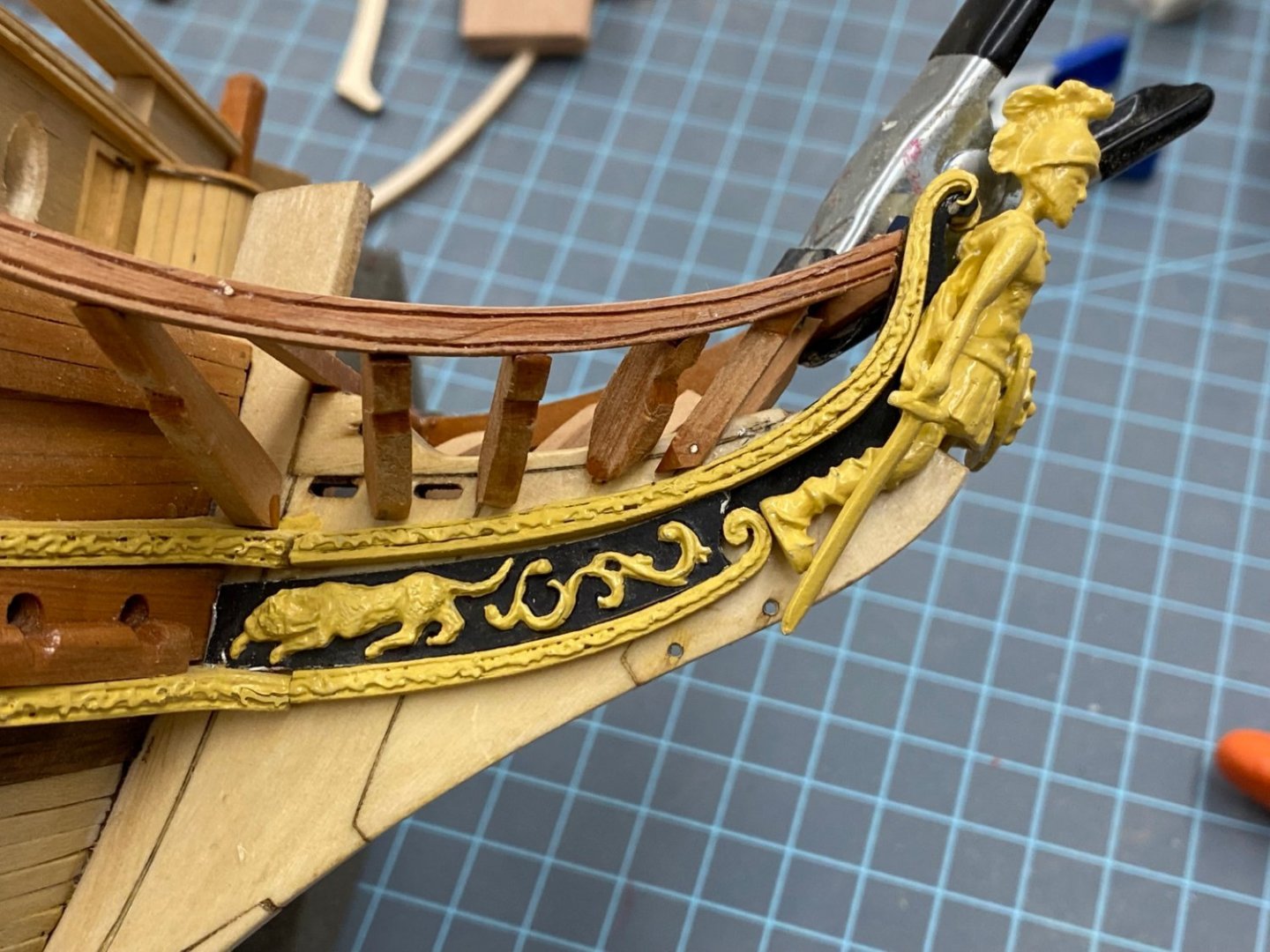
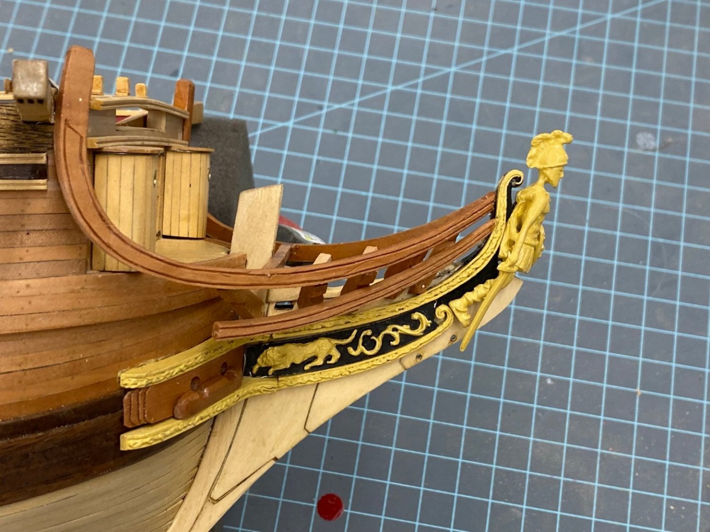
I went back to the starboard side to add the "decorations" and was faced with a choice. I had painted all the decorations as I was doing the stern carvings so the default color for the dedications is sort of yellow. That worked fine at the stern, figurehead and cheeks but for the head rail I thought the yellow would stand out too much (not to mention my likely less than perfect placement) so I decided to paint it something closer to the color of the varnished Swiss Pear. Here is the starboard side with the decorations added. The port side after mid rail is finished and is waiting for the WoP to dry before adding the decorations . N Before I got the final items on the port side done I started the head gratings. Since the structure is in Swiss Pear I toyed with the notion of doing the head grating in Swiss pear as well but decided that the beakhead deck is boxwood that I should make the head grating of boxwood as well. I started (per instructions) with the elements then outline the box for the bowsprit gammoning. Cutting and fitting all those small pieces sounds like as much fun as the head timbers (not really since most of the pieces are somewhat independent of each other, unlike the head timbers). Here is an overhead shot of the bow with the first three head timbers in place.
- 370 replies
-
- 5
-
-
- Model Shipways
- Confederacy
- (and 1 more)
-
Well, at least if I made an error that caused the starboard side mid rail to miss the after two head timbers then I did the same thing on the port side because again, only the first three timbers had to be notched to get the end of the mid rail to approximately where it is on the starboard side. Consistency must be worth a few points. Here is the forward section of the port mid rail awaiting the fabrication and detailing of the after section. I am using the starboard side as the template. It should work, right?
- 370 replies
-
- 4
-
-
- Model Shipways
- Confederacy
- (and 1 more)
-
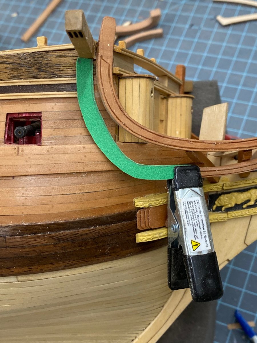
After messing around most of the afternoon trying to fashion the other two pieces of the mid rail (using the kit supplied pieces to make shaping easier than working in the Swiss pear) I finally decided that as long as I am going to fabricate these pieces in Swiss pear, I might as well do it in one piece rather than two. So I made a template out of an old file folder to run from under the cat head to the already attached mid rail. I cut this piece out of 3/16" Swiss pear since the 1/4" thick material is only really needed for the bolster under the cat head (which I will add as a separate piece). I shaped it using the spindle and disk sanders then "adjusted" it with several grits of sanding sticks and a few files. When I was satisfied with the shape I added the molded edges and a pin at the junction with the forward mid rail. Here is what it looks like now - need WoP and the bolster under the cat head. I had to put a notch in the back side to allow the wales to go through, otherwise it would had to bend it and I learned my lesson on adding stress to the model structure. On the port side I will try and get the grain running vertically rather than horizontally as it is here so the part running down from the cat head will look better than it does here. Although after the WoP it may not be as noticable as it is here (at least in the photo).


- 370 replies
-
- 2
-
-
- Model Shipways
- Confederacy
- (and 1 more)
-
I got the starboard side head timbers notched and in place. Not the most "seaman-like" set of head timbers I ever saw but given their location and the head gratings above they will not be very visible. Now for the real fun - getting the mid rail installed. So, as it turns out, if I were to glue the mid rail to all the head timbers it would make the rest of the mid rail quite a convoluted shape. Based on the plans this is not what was intended so I only glued it to the stem and the first three timbers to allow so "flexibility" in where the aft end hangs while I fit the rest of the mid rail.
- 370 replies
-
- 1
-
-
- Model Shipways
- Confederacy
- (and 1 more)
-
Tim, Thanks, it was "touch and go" and still some touch up of the yellow (aka wood) color and WoP. I guess I need to pay more attention to putting stresses on the model and getting enough glue in the right places. I thought maybe he was yelling as some seaman (landsman) who was not getting "with the program". Having seen the modern version of this phenomenon it was the first thing that came to mind. But he could be dancing I guess
-
The head timbers (at least the 10 required before the mid rail is installed) are as complete as I am likely to get them. The next hurdle is finding a way to hold them in place while marking where the mid rail intersects each one, file/chisel a notch in each one, reinstall check the fit, modify as required and repeat as necessary. I am likely to not detail the bottoms of the head timbers as I think this is really overkill and unlikely to ever be observed by anyone. Maybe I will add the decorations but not the molded edge as I am sick of messing with head timbers, or will be by the time I get the mid rail figured out.

- 370 replies
-
- 3
-
-
- Model Shipways
- Confederacy
- (and 1 more)