HOLIDAY DONATION DRIVE - SUPPORT MSW - DO YOUR PART TO KEEP THIS GREAT FORUM GOING! (Only 36 donations so far out of 49,000 members - C'mon guys!)
×


sheepsail
-
Posts
103 -
Joined
-
Last visited
Content Type
Profiles
Forums
Gallery
Events
Everything posted by sheepsail
-

Importing files into Delftship
sheepsail replied to woodartist's topic in CAD and 3D Modelling/Drafting Plans with Software
I just noticed that I somehow uploaded the wrong PDF. That one uploaded is a link to a thread. Part 1-DELFTship_Bkgrd_Images.pdf Part 2-DELFTship_Bkgrd_Images.pdf Part 3-DELFTship_Bkgrd_Images.pdf Part 4-DELFTship_Bkgrd_Images.pdf Part 5-DELFTship_Bkgrd_Images.pdf It is interesting that when I copy the file name, it creates a link to it. Does save searching for it. I think these are buried on the NRG pages. I print these out as I find the hardcopy is easier to use when I am on the WIndows machine. Once I correct the fencepost errors in the Saginaw model, I plan on writing it up in more detail. I got more involved with the physical Forester model which I never imported into DELFTShip. -julie -
Importing files into Delftship
sheepsail replied to woodartist's topic in CAD and 3D Modelling/Drafting Plans with Software
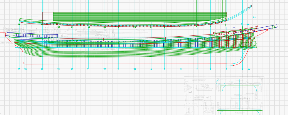
There is a really good tutorial I downloaded. The title is Modelling a ship's hull with Delftship - CAD and 3D Modelling_Drafting Plans with Software - Model Ship World™.pdf When I pasted the title it looks like it attached a link to this thread as well. This is a bit dated, the basics remain. Most of the changes are to the UI graphics. My workflow is to use Lightburn, the laser etching program, which works much like Adobe Illustrator. This is to clean up the drawing. I then export Illustrator. Sadly apple remove support for Postscript and Illustrator in the latest OS. So I have to use an old copy to convert it to PNG. I like PNG as it is not frequency compressed like JPG. DELFTShip has no trouble importing PNG file. There are three background images, which move around to the 6 sides of the cube as the model is moved, so sometimes they are mirrored. Sadly DELFTShip does not import SVG or PDF vector images, only bitmaps. DELFTShip also only runs on Windows, so I have to sneaker net the graphics to a windows machine. The workflow is a bit strange in DELFTShip. It does not use the normal English based verb action syntax. I suspect it is closer to dutch grammar. There are no menus, only Icons. Each Icon group has functions. I also find that there is a lot of keyboard activity using the control rather than the shift key to select things. The three buttons on the mouse, work a bit different as well. Right is used for dragging, rather than pressing down on the scroll wheel. There is also a lot of flipping between the icon ribbons. For some reason one has to edit in the station locations rather than click and drag them. Even though they are highlighted. One really needs to write down the table of offsets. I think the program can import these as a CSV spreadsheet. I have not tried that as yet. Scaling is done either when the images are imported, or in the parameters section. It is easy to get a fencepost, where the model is off by a foot, as the scale starts at zero. I like to number the scale on the drawing. -julie -
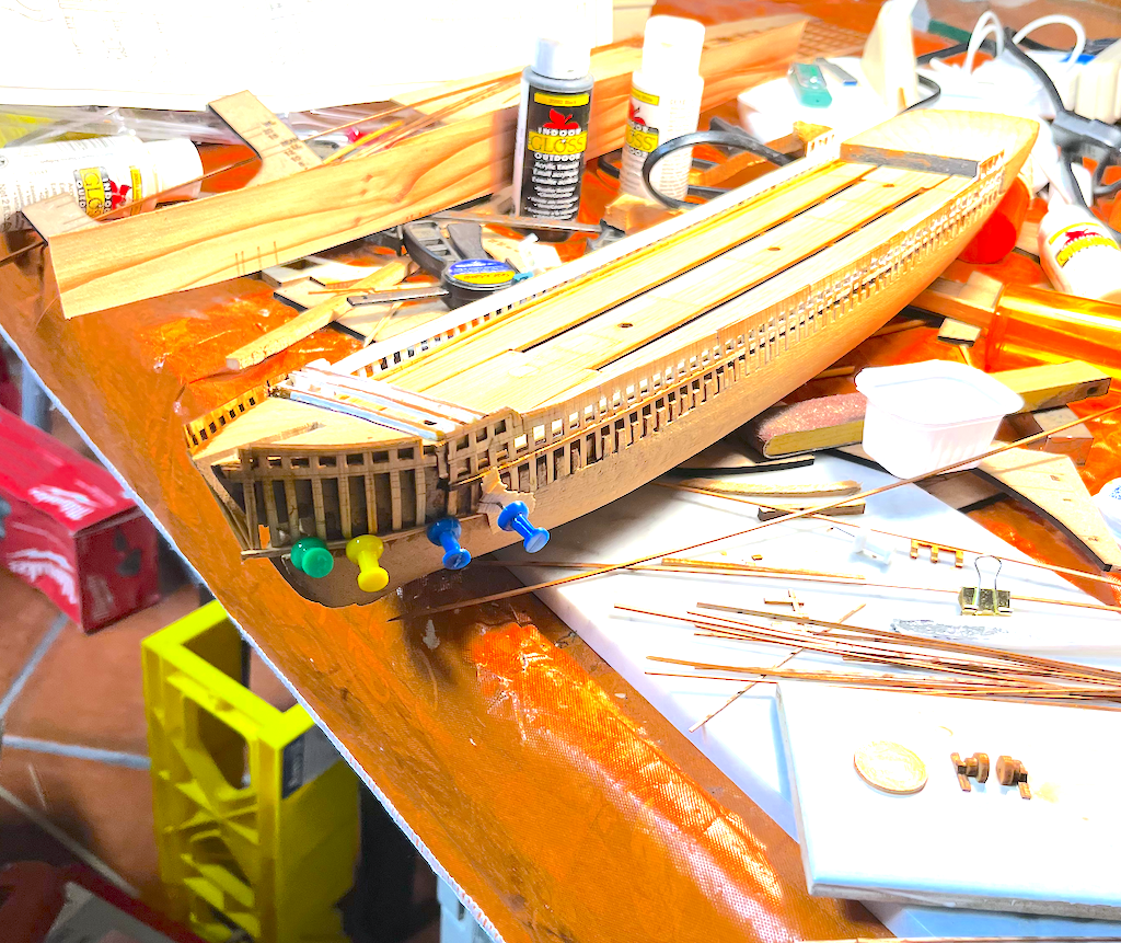
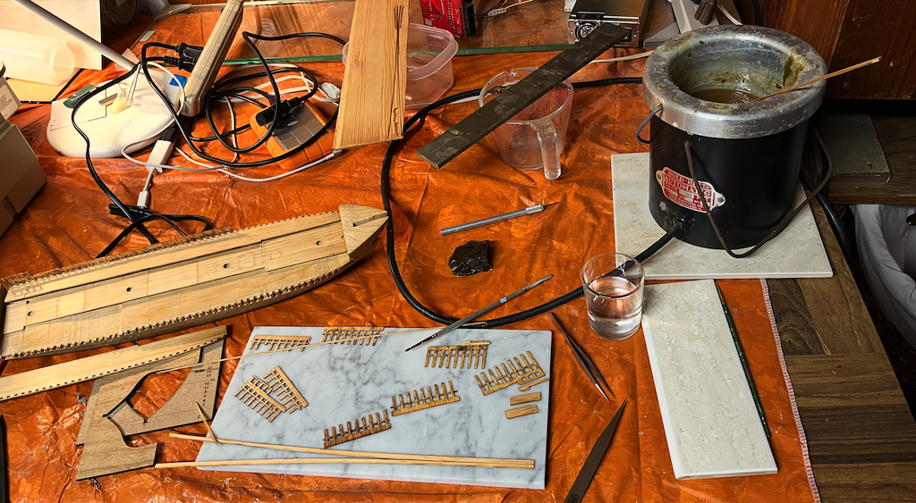
Started planking the hull this week. The hot hide glue is working really well. I find that if I place a few drops into an old plastic spoon. Upper right. I can use a tiny paintbrush to apply a small drop or line to the thin planks which are about 1/32 inch square. Unlike other glues, I can let the blob of unused glue dry and throw it back into the pot. Only minimal clamping is needed. The push pins only need to go in about a milimeter or so. Mostly around the curved parts. On the bulwarks I could use tiny binder clamps. Setup time is fast.

-
Planking disaster
sheepsail replied to sgrez's topic in Building, Framing, Planking and plating a ships hull and deck
Contact cement creeps and stuff shifts about. Has no torsional strength. Can be sort of twisted apart. Does work on stuff like Formica and foam rubber. Not so great on wood to wood joins. I think most people use the casein white glues, such as the Elmer's brand. Had a friend attempt to use gorilla glue for cabinet veneers. Total disaster, humidity caused excess swelling and de-lamination. CA glue is best at gluing skin together. My personal preference is for hide glues, which have been around for centuries. Steep learning curve, and not really the norm anymore. -
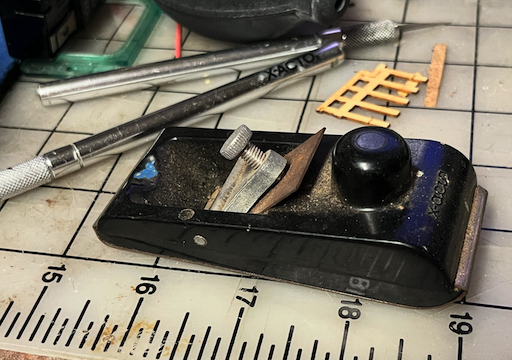
I have a small drum thickness sander to thin down the wood to 1/32. The laser has no issues cutting 1/32 inch sheets. Xacto knifes and micro planes cut through this stuff like butter.
-
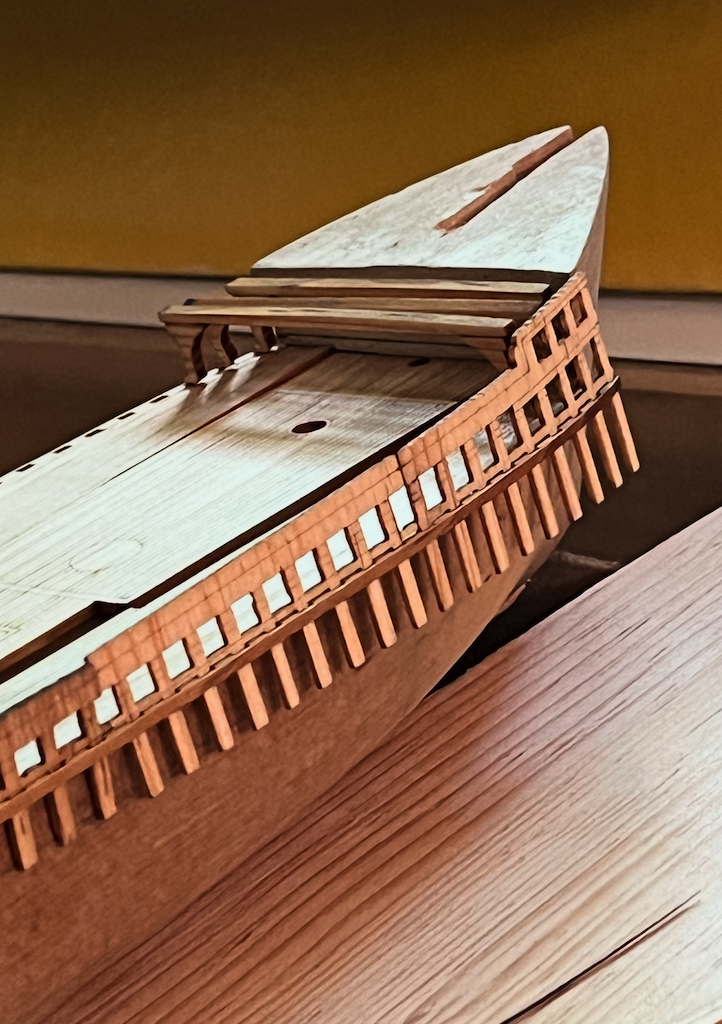
Applying the under supports to the Bow. Feels a bit like more of the same. I borrowed some ideas from the planking section to use push pins. The hull wood is soft enough to press them in. Does leave a big hole. This will all get covered with the "planks." There is a bit of overlap at the stem. I based this grid on the top plan view, and projected it back. The rough kit suppled hull feels a bit undersized when compared to the plans and photographs. The planks where made by tracing some lines off the plans and extending them. The plank wood is about 1/32 thick, which might be a bit large for scale which is 3/32 so that would make the planks 1/3 of a foot or about 4 inches. Ship timbers do seem to be fairly thick, so this might be close. In the lower right, there is some texture for the lower capstan chain winch. This is set next to the ubiquitous coin, which in this case is a penny. For some reason Apple messed up the color calibration in the latest version so the image looks washed out on my screen on the web page, but not in the preview app. If I leave the default settings uploads come out too dark. Ironically I tested this sort of thing for Apple back in the 1990s. The system does work, if one stays inside the walled garden. I left the ends of the planking strips uncut, They still came apart as even the marking pass cuts almost 1/2 through at the lowest setting. Most likely I will need to extend the lower part of the stern. There should be enough material to cover the bulwarks down to around the water line. Below the waterline the planks are pretty much cut and paste. Sorting this stuff out can be a challenge. I probably should have marked the back, like one does piano or organ keys to reposition them. At least this time they did not warp up, so the laser did not shred them. I used an old 2x4, which I think was from a project about 8 or so years ago. Seems pretty dry. Grain is courser than the century old wood. Those blocks are not long enough to cut the full lengths of the planks. This all gets painted.
-
I have an Xacto micro plane, which seems to do the job. Also a wet grinder. Would be nice sometime to find a new blade, although the existing one still works well. -julie
-
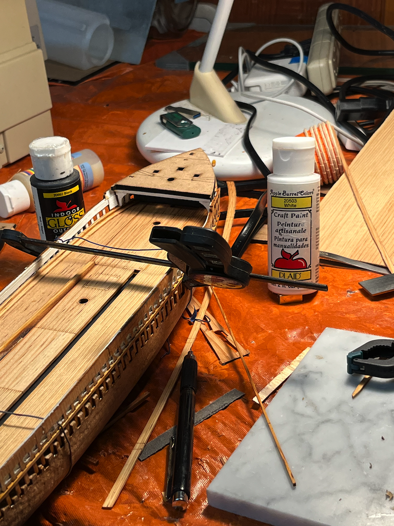
The bottle says 'Plaid' located in Norcross Ga. Label says craft paint. Materials indicate water base acrylic. The grouping is called Apple barrel colors. The gloss says it can be heat set in the oven. They would probably have come from Michael's or Arron Brothers. They are a bit old so could be a bit passed the best buy date. I had to add a bit of water to the brush. Here is a shot of the latest progress with the bottle in the photograph. I had to use stronger clamping on the starboard side. Since the center deck is in place. The deck stringer and forecastle beams are just set in place. There is a bit of a gap as the hull block is a bit wider, or the notches not cut as deep as they should have been. This affects the angles where the forecastle beams attach. Not quite sure how I will compensate for this. I need to wait for the main glue to fully dry and see if I can steam and clamp the bulwarks rail. The deck template is in place as I wanted to see how the shadows work. There probably should be something to represent a locker on the port side. The winch probably should be suggested. May be some time before I get to the deck house. I want to plank the outside of the hull first. Was a bit afraid the bulwarks might be too fragile, The tabs did chip a bit where the laser scored marking lines. Once glued things feel surprisingly strong. Even so there will be no more tossing it into the box with the rest of the sticks. I did glue some of the water ways in place. Not sure yet what to do with the scuppers. These are marked with simple laser lines. The scale and photographs indicate these might be about one meter square. The 'Commerce' has haws pipes in these location. The Ron Cleveland, Rigging of West Coast Barkentines and Schooners, has some stuff on loading which shows how the milled lumber was stacked and chained so the water could align and run out of these holes. One of these holes can just be made out in the rub rail on one of the ref photos I copied in the museum with my phone. As noted the Thayer has a series of slots near the deck level. This was something seen in person, which is probably not too noticeable in photographs. These are large ships. It is hard when working at a small scale to get a feeling for how large some things should be. Probably why they have people in the photo. The deck stringers are over 100 feet in length. According to my scale these are nearly 1 and a half feet on each side. -julie
-
I really can not speak to how well hide glue works in ship modeling as I have no real experience with the more traditional kits and methods. I painted the bulwarks. Not having access to miniature four dimensional dock yard workers, I figured it best to paint things before gluing. My dad had some old paints from various projects. Since I am making this up as I go, using them seemed like the simplest option. The top of the hull, where most of the gouges are was painted with a flat black graphite color. I may make some of the hatches open. The area under the forecastle, behind the galley and crew quarters should disappear in shadow. I am still contemplating modeling some blocks to suggest the capstan winch. Will see what it looks like when I get things together. The milled down sheets from the pipe organ swell shade blades, are not wide enough to cover the whole deck. So I did them in sections. I cut separate thicker pieces for the long deck stringers. Since I had the graphics for some deck stringers. I cut some more without the knee braces. This should help with the installation as there is warping of the decks in three directions. Interesting that when glued up, there are optical illusions which make the straight lines look curved and the curved ones straight. There is a large photograph on the door of the museum to the Forester room. I took a shot of it with my phone. (there are some reflections on the glass.) This shows a bit fuller bow than the model was carved. The station templates do allow for more thickness in these parts. This also shows the ship stripped of most of the fittings. What it looked like shortly before it burned. In the photos, and my recollection the decks were covered with all sorts of junk. The owner at the time was the sort who did a lot of itinerant jobs about town. For the most part hide glue does not need a lot of clamping. I did find that where the forward parts do need to wrap around the bow, that the wood tended to spring back a bit. So I used some telephone wire scrap from a pipe organ relay. When I pre-bent the end of the bulwarks they broke at where I joined the cross grain rails. So I clamped this back after installation of the side and deck structure. Some of this will get filled and sanded so the planking can be laid. The width of the deck was trace from the top view well for shaping these parts. I did cut some test planks from scrap. These feel a bit thicker than scale. For the most part I am finding the parts to align with the traced plans. -julie
-
Thanks for the correction. I could not remember all of the acronym. I posted this yesterday when working with the machine, and did not bother to look it up. Here is a link to the extinct Mediterranean plant. It is quite fascinating Must have tasted good, as it was eaten into extinction. In the end it was worth more than gold.
-
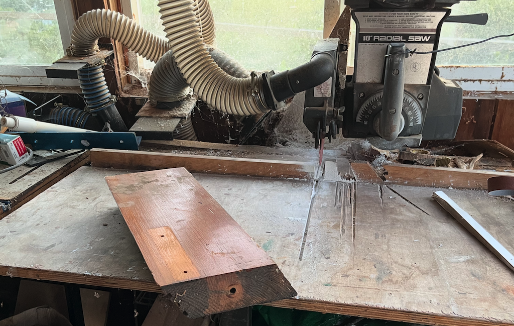
A few other note about the machines. For the most part these are industrial machines. They require an industrial space, with active ventilation flues. Why most of them are placed in shared workspaces or libraries. It takes a fairly powerful laser to cut through 1/4 inch of wood. In addition to the ventilation, there is active cooling involved. Even after cutting the parts tend to outgass from the burned edges. The stuff I cut last night smells a bit like toasted Christmas trees this morning. I have been typically spending 3 or so hours per session. Of this the actual cutting is perhap 10 to 15 minutes. The rest is prep and set up. It probably took a month or so to create the base drawings in lightburn. When actually cutting one has to plan how it fits onto the material. There is also time needed for cleanup. Be ware of the smaller machines. The ones what use small diode lasers and DVD type mechanisms. Even these have large heat sinks. I have a few of these that were popular a decade or so back. Typically they only have about 2x2 inch work area. Sometimes these diode lasers are installed on 3D printer frames. Some of these only will move the laser head in a raster pattern. The resulting accuracy is only as good as the lead screw or syncro/servo belting. -julie
-
Check out my 'Forester' log. I am using a large format engraver in the local Makerspace. I use lightburn and DELFTship. There is stuff on this in the 3D forums. BYTW: I think lazar was a now extinct plant used for food in ancient Rome, till it was all eaten. Laser is Light Amplitude Stimulus Energy Radiation.
-
Old Solid Round Stone Identification Assistance
sheepsail replied to Ashland1's topic in Nautical/Naval History
Dolomite balls were used to make the pyramids and other large megalithic structures. Bang two stones together and one does not need iron or steel hammers and chisels. It has been shown that working sitting in quarry trenches can cut through anything using similar stones. In a leather sling, they also work well for catapult ammunition. Such things also make good ballast stones. They pack well. -julie -
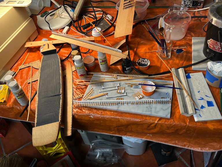
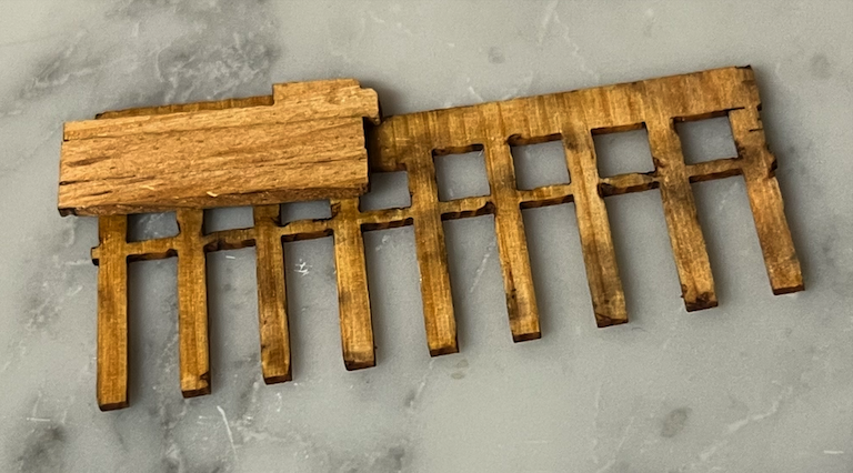
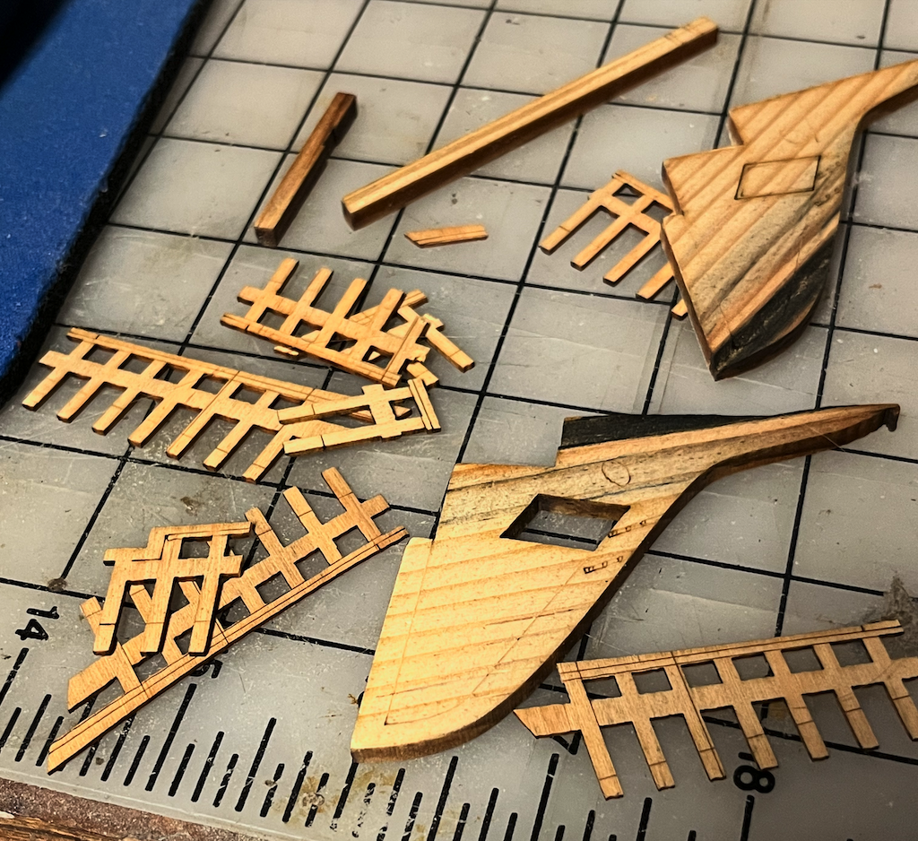
Setting up the workspace in preparation for gluing. My preference is for using traditional hot hide glue. On the Mechanical Music and pipe organ forums, glue is a sordid topic, what was known as the 'glue wars.' The short of it is that in the 1970s restorers started using the PVA and PVC glues. Several companies went out of business as the resulting instruments were seen a ruined due to early failures. Hide glues have been around for centuries they have known lasting properties. One is that with heat and moisture they are for the most part reversible. They are also easy to clean. Usually only minimal clamping is needed. After a few moments the glue forms what some call a death grip. The main disadvantage is that due to the organic nature, It has a distinctive smell. Basically it is expired gelatin. Add sugar and you get gumi bears, which do actually work pretty good as a glue substitute. Gumi candy also makes great printing transfer rollers. I personally have nothing against CA glues. I use them a lot in other things. I find though that it tends to not have much torsional strength. One can usually break the bond by twisting. Resin glues and epoxies have their place as well. Since I am working with century old wood I figured to stay traditional. It is what I am used to working with. So here is the first part glued. And the second ... The first part is about the size of a toothpick. I was able to trace over the plans. which only show a couple of cross sections. This was used to create the beams for the upper deck, Which I think is the one called a forecastle but never pronounced that way. It looks like this is around station 3. For some reason the plans show a hawse pipe. The photographs actually have a large rectangular opening, which I think is what they call a scupper. I noticed on the C. A. Thayer, these were a series of holes at the deck level. The Commerce, does have this haws pipe structure around station 3. I think these holes were also used for the mooring lines to pass through. Photographs of the forester bulwarks show clearly visible timberheads. The plans call the the rails, the Rail stringer and Ceiling. Since they are different thicknesses I cut them as two different pieces. That makes for one long toothpick. what looks large in the plans is only a few millimeters when cut out. Here is the port side glued up and half the starbord side. The resulting structure is quite strong while remaining flexable. There are a few places where the laser cut a bit deep into lower tabs at the top of beam line. These broke off. Since I had everything ready to glue, and I also have the tabs, I figured to glue the back once things are together. I still have plenty of other parts to cut. Next up will be to paint these rails. I do not want to get paint on the nicely etch deck pieces. I also want to pre bend the forward parts where it starts to curve. -julie

-
Yes, most are black and white. There is a cut with the Bonhams promotional poster and one of the auctioned fakes in color from 1997. Pereyni also faked other maritime artist some what are shown in color. You really should read the book. It is a real eye opener. There is also a big spoiler I do not want to mention here, what affects the current state of how things get done in our modern society. Ironically the fakes can sell for as much and are almost as collectable. -julie
-
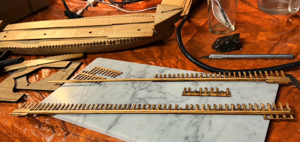
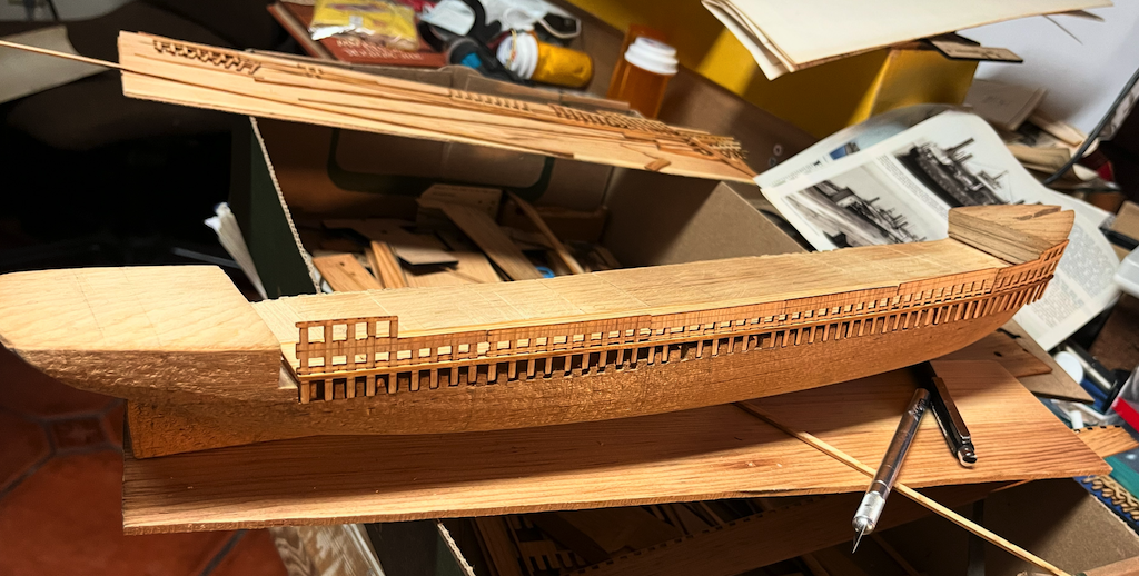
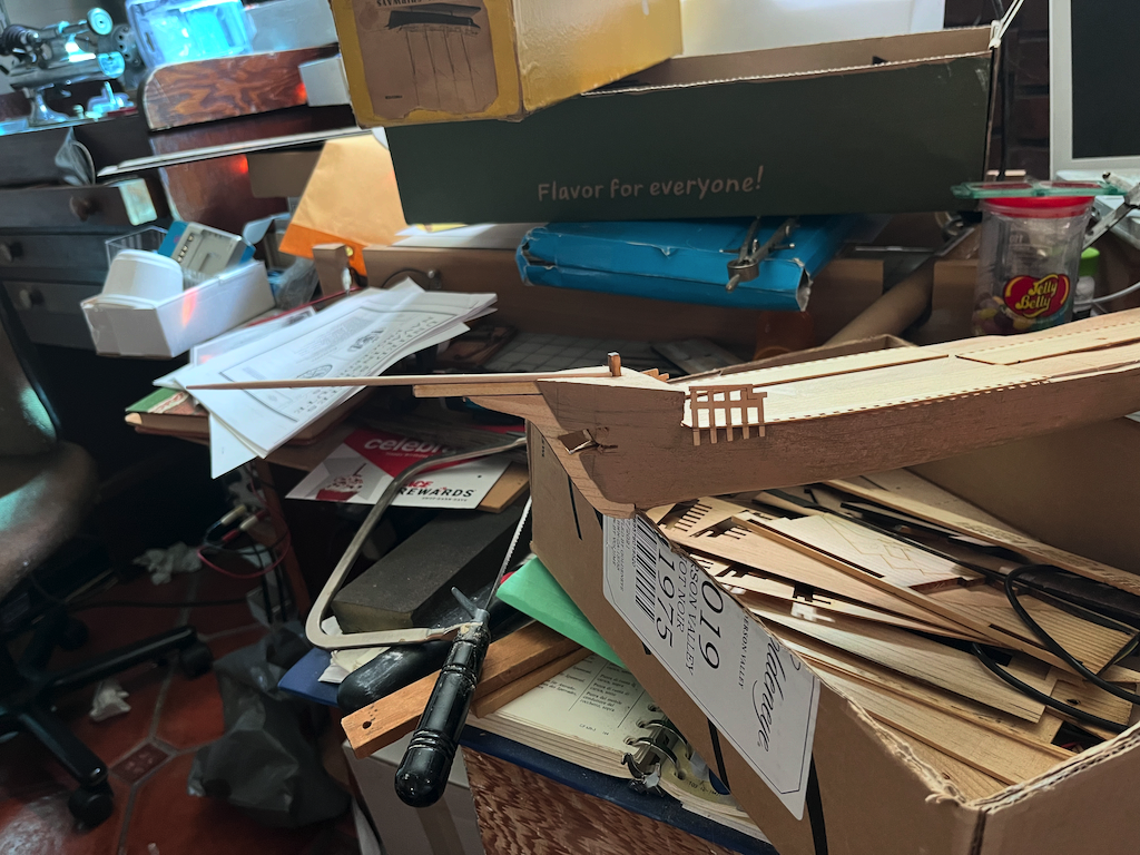
Dry fit of the bulwarks pieces on the hull block. 108 notches cut into the hull for the timberhead posts. To get the grain to align each subsection has 9 posts. They fit surprisingly well feel a bit like pressing together lego blocks. The ubiquitous #11 blade worked well so each notch only took a few minutes. So this only took three days with a lot of breaks between sections. Does show a bit where the saw gouged out the hull. Decided to leave this rough since it will be hidden. There does remain an option to leave some of the deck hatches open. The bow has a whole superstructure that follows the same lines. The hull carving seems to be a bit undersized from the drawings in this area. The test planks are around 2mm so this will bring it in line with the forward templates. This wood is surprisingly workable. Did break off a few of the lower posts where the laser weakened the wood. I could recut these, however I am motivated to install some of these parts to see what they look like. The next step should be gluing some of this together along with some preliminary inside painting, The long rail and ceiling stringers will glue with a cross grain direction, sort of like homemade plywood. -julie
-
The link to the Wikipedia on Ken Pereny's book, where he makes claims to the forgeries. No one could prove any collusion which is why he titled the book Caveat Emptor. He describes in the book in detail how he did the forgeries. And how he got off of the FBI charges once the statute of limitations expired. Buttersworth is not exactly a household name, So I was surprised to see it here. Forgers tend to target deep pocket collectors who have everything and want something no one else can have. In the watch world there are names like Patek Philipe, Audumars Puget, and Jager-Le Coultre, who leave brands like Rolex and Omega in the dust. You only hear of these names if you are in certain circles. Note: this is all off the top of my head, so I may have the spelling of names wrong. (I am actually carving bulwark slots on my model while leaving these forums open, which I check between each subsection. - One subsection left to do.) -julie
-
Accidently clicked on this thread. All I can say is AMAZING. Also interesting to see Buttersworth mentioned outside art fraud books. One of the most forged 20th century artists. I would not trust any Buttersworth to be accurate. Probably as real as a Rolex watch.
-
On the watch forums, there are complaints about used second hand watches. mostly Swiss, being hit with 35% tariff even if coming from other countries. Even sending a watch to another country for repair, can get hit with import duty. Turns out the Tariff is based on country of origin. China was shipping things through Vietnam, so this is a way of closing that loophole. So anything coming from Europe through Canada still gets hit with the higher rate. Otherwise China could simply ship to Canada or Mexico first. Not sure how some of this affects collectables aka antiques. These though are subject to capitol gains tax according to the armchair experts on the watch forums. eBay has to report some of this to the IRS if one sells too much. This is all uncharted water. No one really knows what is true anymore. Especially with computers where anything you tell me three times is true. Or so said the Red queen to Alice ... -julie
-
I am finding this build most inspiring. Getting a feel for 'scale.' My 'Forester' is 1:128. Which is way smaller than I wanted. I am using CAD (lightburn) and a laser to cut part. It always amazes me when I print them out and they are so small. I could almost use toothpicks as raw stock. In my research on other local shipwrecks, I learned about the local train ferry's . At 424 feet these were some of the largest wooden ships built. (Which I find hard to believe. What about the Orient express and cross channel ferries? ) The local ferries could load 4 trains on each. 116 feet wide! A relation is into Model train's. I believe mostly in the HO scale. I asked if anyone ever modeled these. A magazine article showed up in the mailbox from a 'Railroad Model Craftsman' Noted that the resulting model was over 5 feet. They also modeled the slipway which used counterweights to load the trains. So the result was over 9 feet including the rail yard. The remains of these slipways are still visible on the shoreline. One of the ferries was abandoned in Antioch, nearby near the local coal mines. The engine A frames still visible as of 2007. I think these mines were soft coal. The article noted that the oil burned to hot, so they had to return to using coal. They had 4 distinctive smoke stacks and were side wheel powered. The ferries ran from 1879 till the bridge was built in the 1930s. The other ferry is buried underneath the California Maritime Academy in Vallejo. Both completely forgotten. I had to look up HO scale which is 1:87. Looks like the toy cars are 1:64 which would be the scale, I was thinking of using for my next model. I actually have my grid set to 3/16 which means each square in the CAD is 2 feet. Normally I work in mm scale on pipe organs and watches, so working in inch feet in ways feels strange. Looking at my architect scale and the model at hand it looks like if one was to model one of the ferries, the results would be close to a meter or so in length (I grew up in the 1970s with both systems. Learned like language it is ludicrous to convert between the two. Just use what ever is more convenient as long as one is not landing on mars.) Curiously I had to look up the Nemi ships, which I thought were similar is size to the ferries. Turn out at 70 meters by 20 meters they were half as large. Since giggle AI tells me this is 230 feet by 60 feet. Even if 20 meters is 20 meters and the size of the Bocci court in the back yard. Of course we could use football fields and furlongs, to be just as descriptive. It is so easy to not get a feel of scale from the photographs of the Hard coal stern wheeler. This just means that I am in awe of the modeling skills here and look forward to the next installment of this build. Great work. -julie
- 457 replies
-
- 4
-

-

-
- sternwheeler
- Hard Coal Navy
- (and 1 more)
-
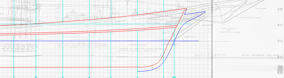
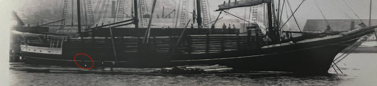
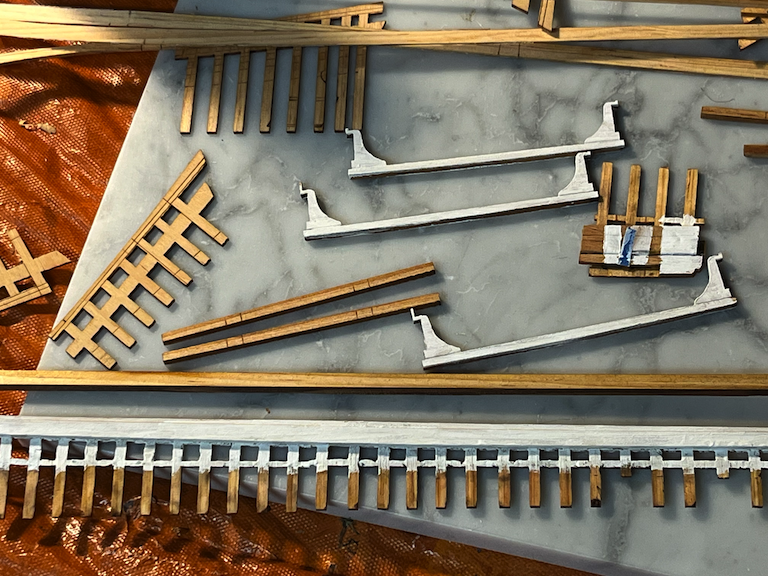
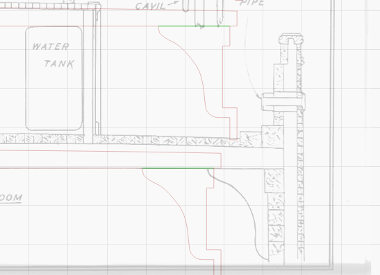
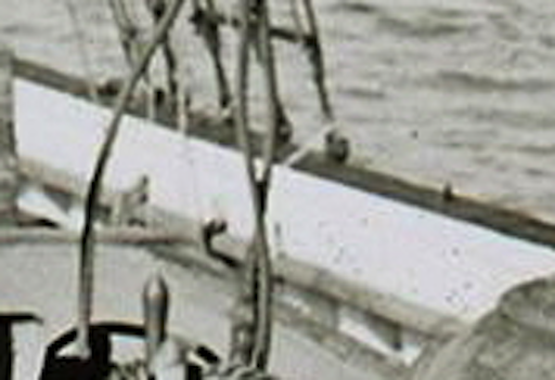
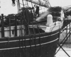
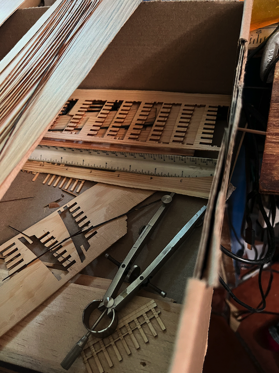
More time yesterday with the laser. The hardest part is figuring out what parts to cut first. The deck and bullwarks is the obvious choice. When making the test pieces, it seemed logical to extend the decks the full length. The wood must be spliced, in the photos and at this scale that is hard to see. I probably should have cut the waterways. Really wanted the side planking to experiment with. More on that below. One thing intrigued me is a zoom in from this photo. Which will probably be referenced a lot in these build logs. Since the upper deck seems to have beams and knees visible, this looked like it would be fun to model. These need to work with the timberheads I really wanted to see what this would look like. This is also an area where the bandsaw cut deep and angled from when I removed the crew quarters deck house. I was quite pleased with the results. Most of this will be lost in shadow. Does mean I will need to think about how I am going to paint things and with what. It also brings up whether or not to model some of the chain windlass. Most of that stucture is in the solid part. I used the station what intersects the capstan as a reference point when I sawed the blockhouse off. There are also hints in the sparse plans that there was a locker on the port side. There is a door visible in the cross section. A corner of this is shown attached to one of the port side bits. Using the laser to mark the machine sanded planks, looks like no other finish will really be needed. It feels odd to be working with hundred year old wood. Does seem to make a difference in a way. Wurlitzer was in North Tonawanda NY. This to be close to the locally supplied materials. These instruments were mass produced. In the thousands for so many to survive. There were also West coast theater organ builders. Always thought it interesting that there was a desire for the pipe organ to be imported from some distance away. All this came to a collapse when sound films became popular. The silent film era lasted such a short time from about 1925 to 1927. By the early 1930s few theaters were being built. The market saturated as pretty much every town had a theater or two, and the large cities dozens. The hull planks were not as successful. Since this was somewhat a test I used the last board which was only sanded on one side. The other side was painted with a flat black paint. The test plank also does not run the full length of the ship. I had marked out using a diagram I found in the planking subsection of a 4 butt order. I figured that I could run the program twice. Extra planks would no be a bad thing to have either. I figured not to cut through the outer edges of the planks. Since the planks are over long I labeled this edges with letters. Used the wrong setting and these cut through. The other edge was off the board. The first cuts came out great. These are not closed paths so the cut in the draw edit order. After a bit the aft planks started to curl up. The laser then proceeded to shred through the loose planks. Not a complete loss. These were test planks anyway. Most of the forward planks did not curl. These are surprisingly robust, springy and supple. I can line up three or so and lay them on top of the model. There they flow much like the planks in the photo what inspired me to build this ship. The laser only goes so far. There is still a lot of hand work needed. I noticed that in the box, along with scrap pieces, that the tools of the trade do remain. -julie
-
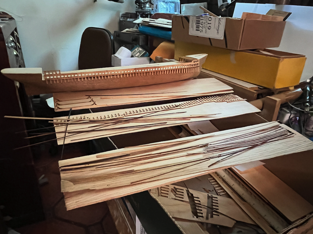
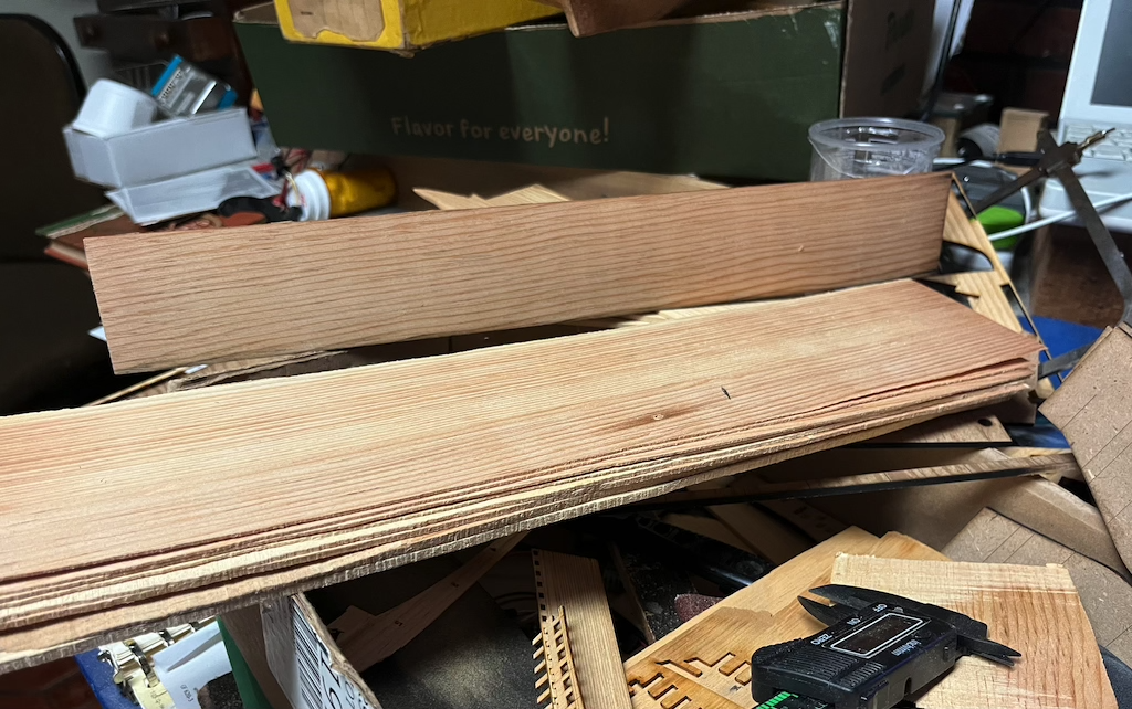
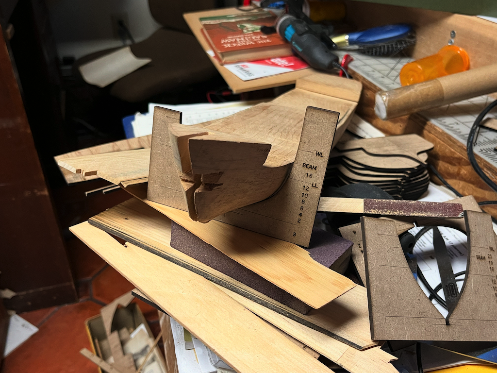
Planed down the block of wood with the thickness sander in preparation for more laser time this week. It is amazing how little of the block is left. The first slice was in the thickness direction which shows the height, in the background, of the block. This was sliced into 3/16th strips, which would be around two feet at the 3/32 scale. The sander will go down to around 0.04 which is about what the plans show the planking thickness. This would be around 5 inches of scale. 4.8 inches is the quick calculation. Did more tracing of the plan documents. The plans show plank placements, so I traced over them. on the bow side I simply copied and pasted the first planking line. This extends out a bit. Since there is some 2 to 3D projection involved, it will be interesting to see how this wraps around the model. The sheets are thin enough to actually do some of this warping while test fitting. Moved some of the timberheads around and decided to extend the deck all the way. The band saw bought deeper into the deck space than I initially thought. In places it is almost 1/4 inch below the 'top of beam' line. It is easy to get lost in the zoomed in scale of the program. A single pixel can represent three inches. So it often seems there should be more space, than the scale allows for. A similar effect happens when I work on watches where the world of small, can feel quite large. The aft section required a lot more warping to match the drawing lines. I had removed quite a bit of the aft cabin, all the way back to station 14. So it looked best to draw things down to the point which was marked load line. This is about where the side view drawing ends. There may also be a bit of camera keystone distortion in this area. There are some definite creases in the paper which were hard to iron out. One could spend a lot of time on this. Or I could build a large format scanner, which would also take forever. I have 600 pipe organ (orchestrion rolls) which have been waiting 25 years for me to do a similar project. I am not all that fond of filling up my phone with a bunch of images, since once captured are hard to delete. There was also a small sheet with a couple of cross sections. This says sheet 3 of three. Which seems odd as there should me more, like the arrangements of the cabins. The C. A. Thayer documents note that the cabins were remodeled a few times. Photos of the Forester show a much wider companionway. What is interesting is overlaying and scaling these drawings, show that they are quite consistent. With the deck and side planking lining up. -julie
-
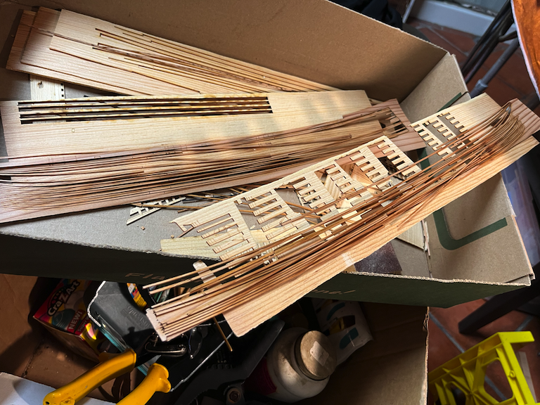
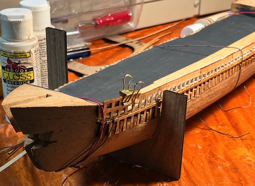
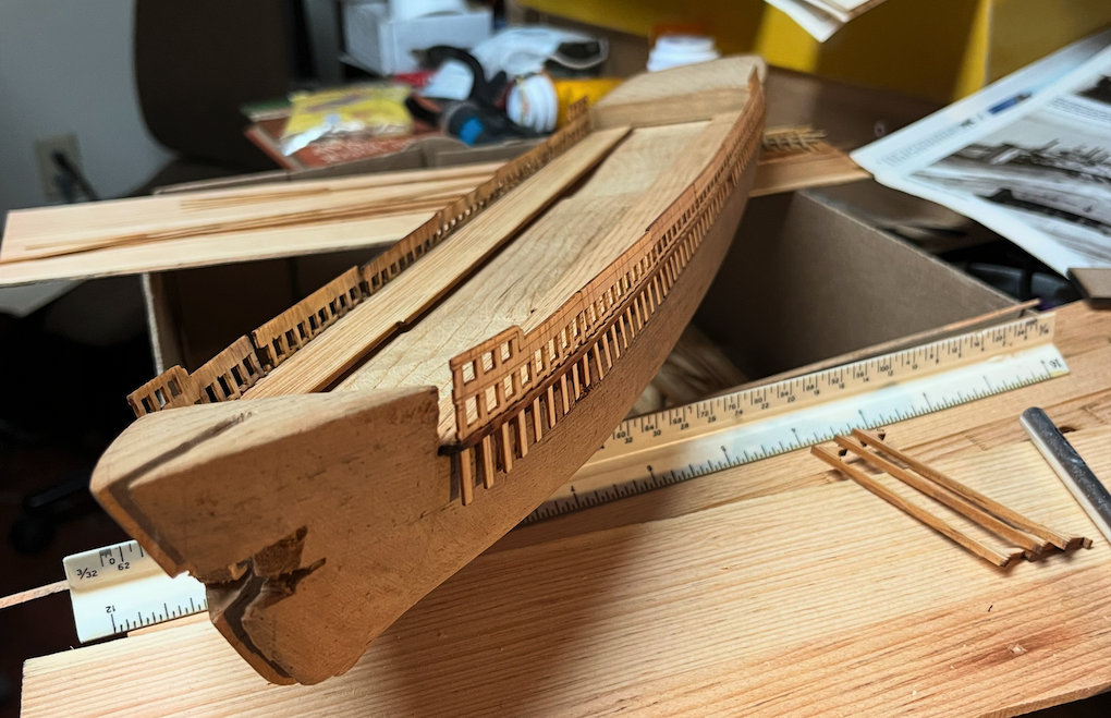
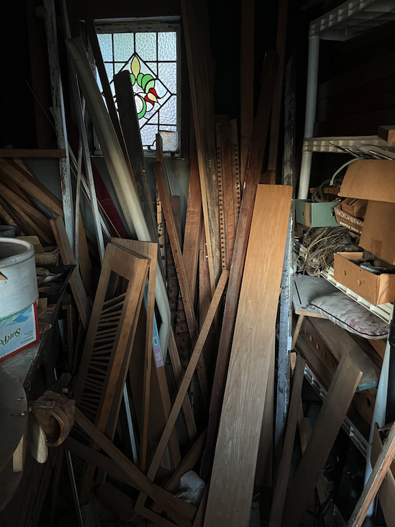
A lot happening near these waters this week. Last week I did some more hacking on the bow of my model. I thought I had updated this log, Not seeing these images will start with them first. Over the last 25 or so years, I have been an organ builder. Mostly making small crank organs. Over the years I have collected a fair amount of wood, which has been in my workshop for some time now. . Some of these scraps are quite old. When a large Wurlitzer was installed the framing for the swell shades what control volume was too short. Since re-framing the chambers was out of the question the bottom foot of the shutter blades was cut off. In order to block sound this is dense wood. The organ dates to the 1920s, so this wood is at least 100 years old. With tight straight grain. I was able to use the band saw and slice off some thin strips, which could then be run through the thickness drum sander. I wanted to see how thin I could sand a piece. I then proceeded to hack up the bow of my model. Probably should not continuing to use the band saw on it, but it is so tempting. Lumber ships have doors in the bow for loading long timbers into the hold. I decided to open up this section. Turns out angles projected on one side, do not mirror on the other. This is where things get a bit interesting. Over the weekend, thelocal San Francisco Model Shipbuilders met at the Vallejo Maritime museum. I was able to meet Clare Hess @catopower In person. Clare was kind enough to loan me his research on West coast lumber schooners. Mostly relating to the C. A. Thayer. This was a large folder which included the unpublished Ron Cleveland Rigging of West Coast Barkentines and Schooners. What was most interesting was a section at the end what described how the lumber was loaded, using the donkey engine and some of the mast booms as cranes. I can not thank Clare enough for this topical info. I had already cut out the lumber ports as seen above. Not quite sure if they can be modeled. From what I learned is they were calked in place, So it looks like they were plugs inserted from the inside. which would be tricky with the solid model. An added treat, was after the meeting, a few of us went to Mare island, for lunch. Some of the Local Tall ships are currently berthed while the Hyde street pier is being refurbished. So it was interesting to see the C. A. Thayer in person. Since it never rains but pours; Clare also loaned me his Saginaw notes as well. I was going to write up some of the DELFTShip stuff as well, only to discover I had a fundamental error in my virtual model as I had the Saginaw at 152 feet instead of 155 feet. A lot of the work I have been doing is tracing over the plans with laser cutting software. I have yet to put the Forester hull into DELFTShip since this one is a physical model. Mostly I use Mac, and DELFTShip only runs on windows. I did not have the thin slabs of wood prepared last week. I was not able to access the Laser until yesterday. Now things are starting to look like kit parts. I did not have enough time to set up all the timberheads. The focus was more on the stem and bowsprit. The century old wood cuts wonderful. The thin stuff is so flexible, although it is easy to break it. Eventually the bulwarks will be glued cross grain. There is some distortion where the parts have steep curvature. Most of this will be covered with the outer planking and molding. I wanted to try setting up some of the deck. Since I over cut the hull with the band saw, I projected the centers of the timberheads onto one of the thin pieces of stock. This gives a place for them to fit into a sort of socket. Here things are with everything just set in place. One of the sticks that came in the kit box looks like it is intended for a jib boom. So it is quite fascinating to see things together for the first time. -julie
-
Make me realize how lucky I am to have the wreak of the Forester so close. Where I can even got down at low tide and pick up pieces and examine them. Not something most people can do. Even with countless photographs, there are still many questions. So many of these were identical, it is hard to tell them apart and know if the detail is a different ship, or was it changed over the years. Tracing over the kit drawings, shows even more discrepancy. Even when you have the evidence, questions remain. -julie
-
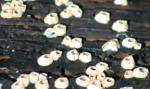
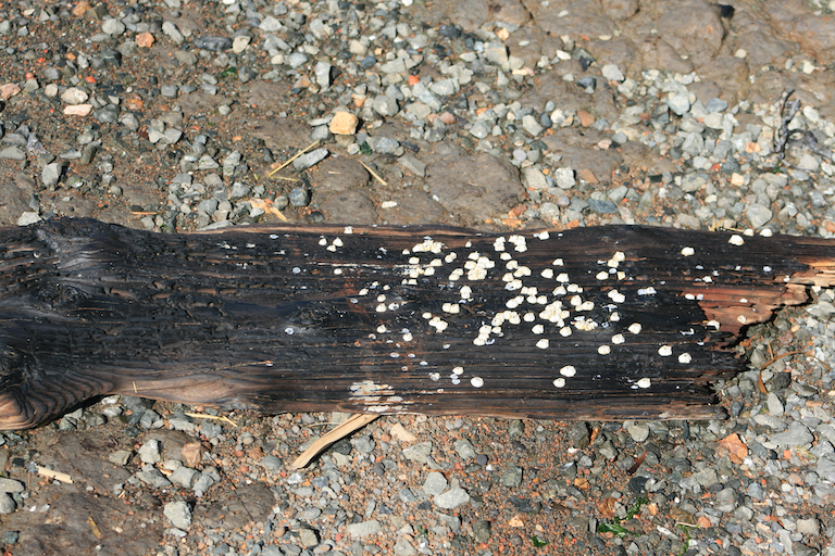
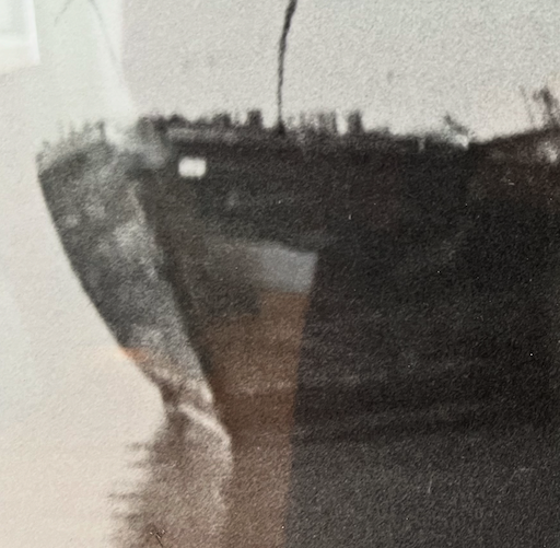
Another field trip this morning. There was a -0.3 foot tide. So most of the wreak was exposed. There is a YT video of a kid running around the wreak when it is in this condition. I found though that the mud is pretty soft, so one would sink down about a foot or so into it. I loaded in more of the plans to lightburn. Then copied over the existing templates what I cut with the laser. There was too much tilt between the two images. Bit lazy to re photograph them. I was attempting to align the two half images with the shroud stays. So having looked for a couple days at these on the plan this was the photo I wanted. Shows some nice construction detail. I also notice there were a few of these braces visible near the stern. This is the port side looking aft. Such would be a good candidate for the fiber laser, such could be cut from old used razor blades. Looks like the ship has a few visitors. See if you can spot them. There was an interesting piece of driftwood. I took some photos of it. There was a time when such things were fair game, now with 1000s of people enjoying this it is probably best to leave it in place. Would be fun to use some actual wood in the model. Not sure how often that is done. But this is not the place to do that. Besides I like the pun. I probably should make one of those archeological poles with the tape on them. Although for the most part it is hard to get close to the actual wreak. Which is quite large. The driftwood was about 2 feet by 10 or so inches. It is interesting to study the wood. Looks like common fir, not to different than framing lumber. Nice straight grain. Probably excellent for making a violin, since it has been pickled in brine for 50 years. Here is a closeup of the critters what were attached to it. Can not really have a ship without barnacles. While I was there, group of about 20 people came by to pose for a group photo with the wreak in the background. Pretty good for something that has been rotting away for 50 years. Probably will not be much visible in the next 10 to 20 years or so. Surprising that there is so much metal. Some accounts were that some of these ships were burned just to recover the metal. What looked earlier like carriage bolts, are probably spikes used to hold things together. Which make me think of Nemi and Sutton Hoo where only the spikes were left. I am thinking of hacking away more of the bow on the model, slotting back to the samson post. May also cut into the front where the lumber loading doors were. In the photo the planking changes direction at that point. Wonder how they closed them to keep them water tight? No hinges are visible in the photographs. The instructions show some large (almost out of scale) hinges. -julie