HOLIDAY DONATION DRIVE - SUPPORT MSW - DO YOUR PART TO KEEP THIS GREAT FORUM GOING! (Only 66 donations so far out of 49,000 members - Can we at least get100? C'mon guys!)
×


FlounderFillet5
-
Posts
139 -
Joined
-
Last visited
Content Type
Profiles
Forums
Gallery
Events
Everything posted by FlounderFillet5
-
Gulf, after writing this post, I am adding this little blurb. I am sorry before you read this that it is so long and kind of off topic (it is all about CA vs wood glue and when it is appropriate to use each). I don't mean to high jack your build log or anything but I though it was relevant info and it is a response to Mike's post above. So, I think the answer to that is that it depends. Items that aren't under a lot of stress should have no problem. This false keel piece should have no problem considering it is glued to the hull, possibly pained over (depending on how far down the hull you paint), and then copper plated over. This thing should stay secure indefinitely, I would think. Other things, like if you plank the hull of the ship or if the method Gulf used to bend a piece of wood to the shape of the false keel piece, where you are bending wood and the wood wants to unbend, I would use wood glue because that will be a very strong joint and the joint will be under pressure until the wood finally gives up (I'm only guessing that the wood will, over time, take the shape you bent it to, but that may take years, I'm not sure). On this build, the only parts I would be concerned about using CA on would be the cleats, on which, the running rigging will be tied. Those cleats will be subject to the tension in the lines which may be significant in this scale. I think Chuck's solution to this makes it so CA should be fine, however. He instructs you to cut off the little prong thing from the bottom of the cleat base, drill a small hole (I think I used a #76 or #78 drill hit here), glue a small piece of wire in the hole so that a short post (slightly shorter than the bulwark stanchions are thick) protrudes. Then, to secure the cleats to the bulwark stanchions or the base of the masts, just drill a hole into them deep enough to take the entire post on the base of the cleat and use CA to secure it in place. I am pretty confident that CA should be sufficient over time when you follow Chuck's method. I know this was a long post but I hope it helps. Keep in mind that I have not been modelling for years and don't know difinitively whether or not what I said in this post is absolutely true, but these are my thoughts on the subject and when I think about it, these points seem reasonable and likely in my mind. Take my advice with a grain of salt or correct me if you know better than me, as I said, these are just my thoughts on the subject.
- 85 replies
-
- 1
-

-
- phantom
- model shipways
- (and 1 more)
-
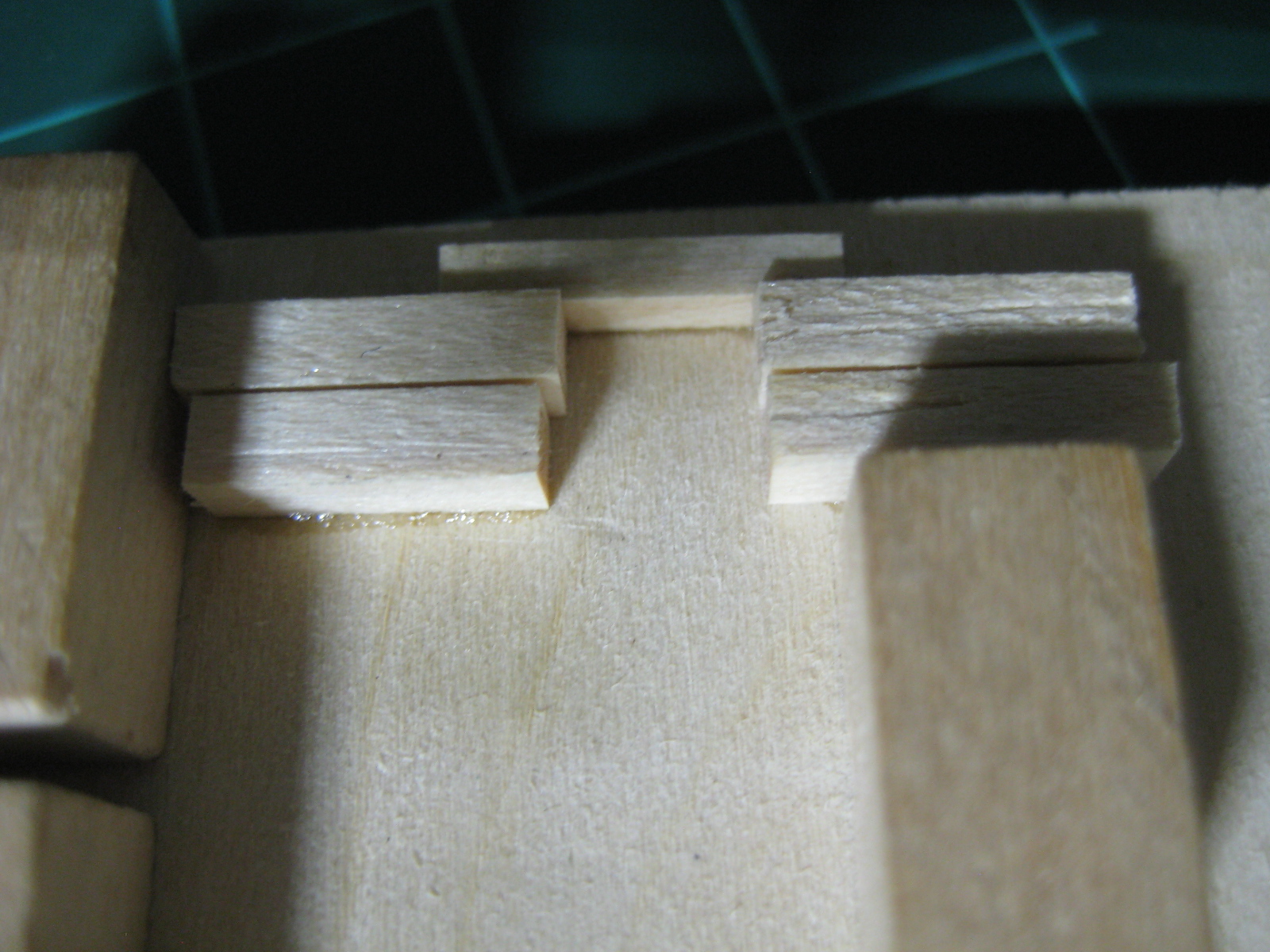
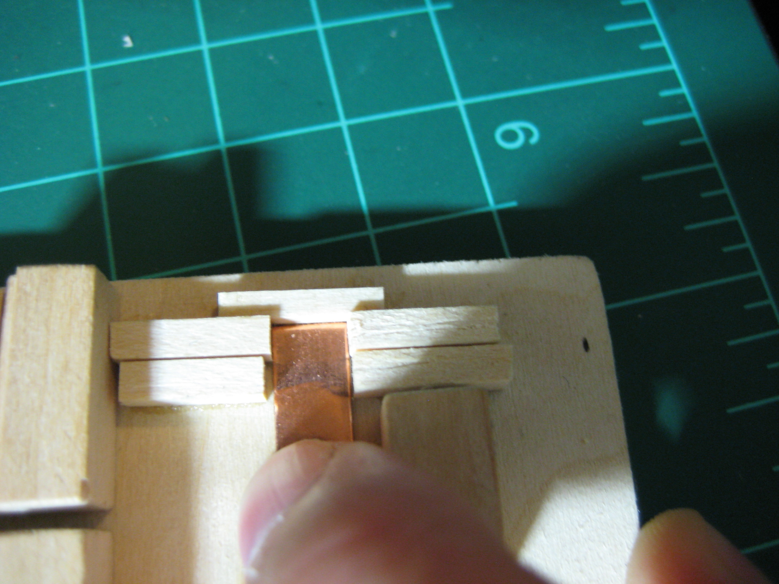
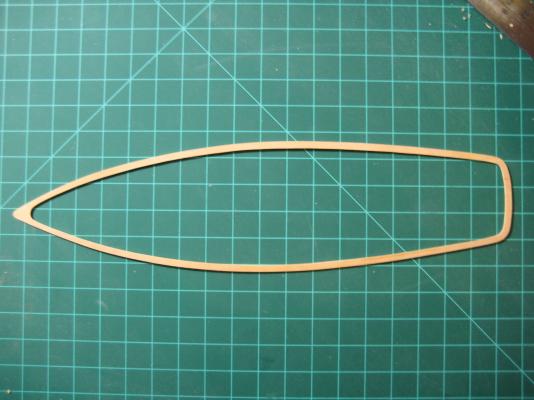
I think I just used some medium CA to glue the pieces together and held them together by hand for about 30 secs until they were relatively secure. Once they finished drying completely, it was easy to cut the piece out. To be honest I don't think I have used almost any wood glue on this build, the CA has been suitable for most things. I think wood glue is more useful for builds that you are planning the hull where you might need to adjust a bit before clamping.
-
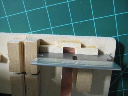
Gulf, What I did to make the shallow cuts was I had a second plexiglass sheet that I made a mistake on while cutting the little slit for the saw blade and I used both stacked on one another to make the saw blade not protrude nearly as much. When I tested it on some wood, it was still too deep of a cut and cut right through the wood so I began trying to use scraps of wood of various thicknesses to sandwich between the two plexiglass sheets until I found the setup that gave me the depth of cut I was looking for. Just keep in mind that this was not a precise method and was likely not the safest one either so if you try it out, be sure to have safety in mind and clamp down your plexiglass sandwich quite well so nothing slips and you don't end up shedding blood like I did earlier in the build haha. Sam, I think the Admiral would not take too kindly to me taking a ship building leave of absence from school but that sure would be nice! Lol. I have actually been doing a little bit of work on my Benjamin Latham kit (build log to come) but I'm a little intimidated by the whole POB thing and I might come back to my Phantom to make some good progress before school starts back up again. I still need to build my little home made wood turning lathe for the masts on this ship and I think this break might be the perfect opportunity to do so. If I do, I will probably document that little side project here as I will be using it on this build.
-
Gulf, glad to see you back in the boat yard! I can say that I have had very little luck with bending wood as I get similar results as what you got but for the false keel on the Phantom, it will be painted over/copper plated over and you won't be able to tell which way the grain of the wood is going. I did it chucks way and was happy with the result. Hope this helps bud, Max
-
Gulf, That is a useful link for the conversion calculator.. saves a little time from doing it in your head. I have seen a few other builds in the past with various flags flying and they definitely add something to the finished model. When I get closer to completing mine, I will have to do a little bit of research to see what would have realistically been flying back in the day. I have seen some that have the flags that represent 1868, some that show there is a pilot on board and others that were to lead other nearby ships and communicate. As for your template problem, the #4 template is clearly wrong where it has the centerline marked. I think I just moved the centerline over 1/16" from where the template goes flat for the false keel. You basically want a 1/8" wide flat area on the bottom of the hull to fix the false keel to. There should be no flat area showing on either side of the false keel and that is where the shape of the hull begins. My suggestion for fixing that template is to just measure 1/16" over from the point where it goes from the shape of the hull to the flat bottom part and make that your new centerline. Adam, you crack me up too man! grate.. haha But you are absolutely right in that as long as you like what you made, that's all that matters. Well thats it for me for now. Until next time,
-
Hey Gulf, The build is coming along very well so far, keep up the great work as you are on your way to a fine model as long as you stay patient and pay attention to detail all the way through. About the grating, I'm not sure if you were referencing my Phantom build but that was something I felt a need to change since the kit supplied grating was, in my opinion, grossly oversized. I think the conversion ratio you are looking for is going to be the same scale as your kit. In the case of the Phantom, it would 1:96 or sometimes it is more useful to go with 1ft = 1/8in. I had some trouble finding good source material for doing research on the Phantom so I just try to think of either what size a part from the kit would be in full scale to decide if it would be reasonable( like with the grating, take a measurement of the width of the holes and think about what it would equate to full scale. If I recall correctly, the holes in the grate would have been a foot or more square... At that size, you would fall in and break ankles!). The other way to do it is think of what the size of something in full scale would be and then scale it down accordingly. Right now, I am working on either filing the kit supplied cleats down or scratch building new ones because I figure they would be about 18-24" long in full scale but the kit supplied cleats were something like 3/8" long which would be about 3ft once sized up. There is likely a more accurate way to go about making sure your model is in scale but I figure a little bit of common sense and thought can go a long way. Hope this helps!
- 85 replies
-
- 2
-
-
- phantom
- model shipways
- (and 1 more)
-
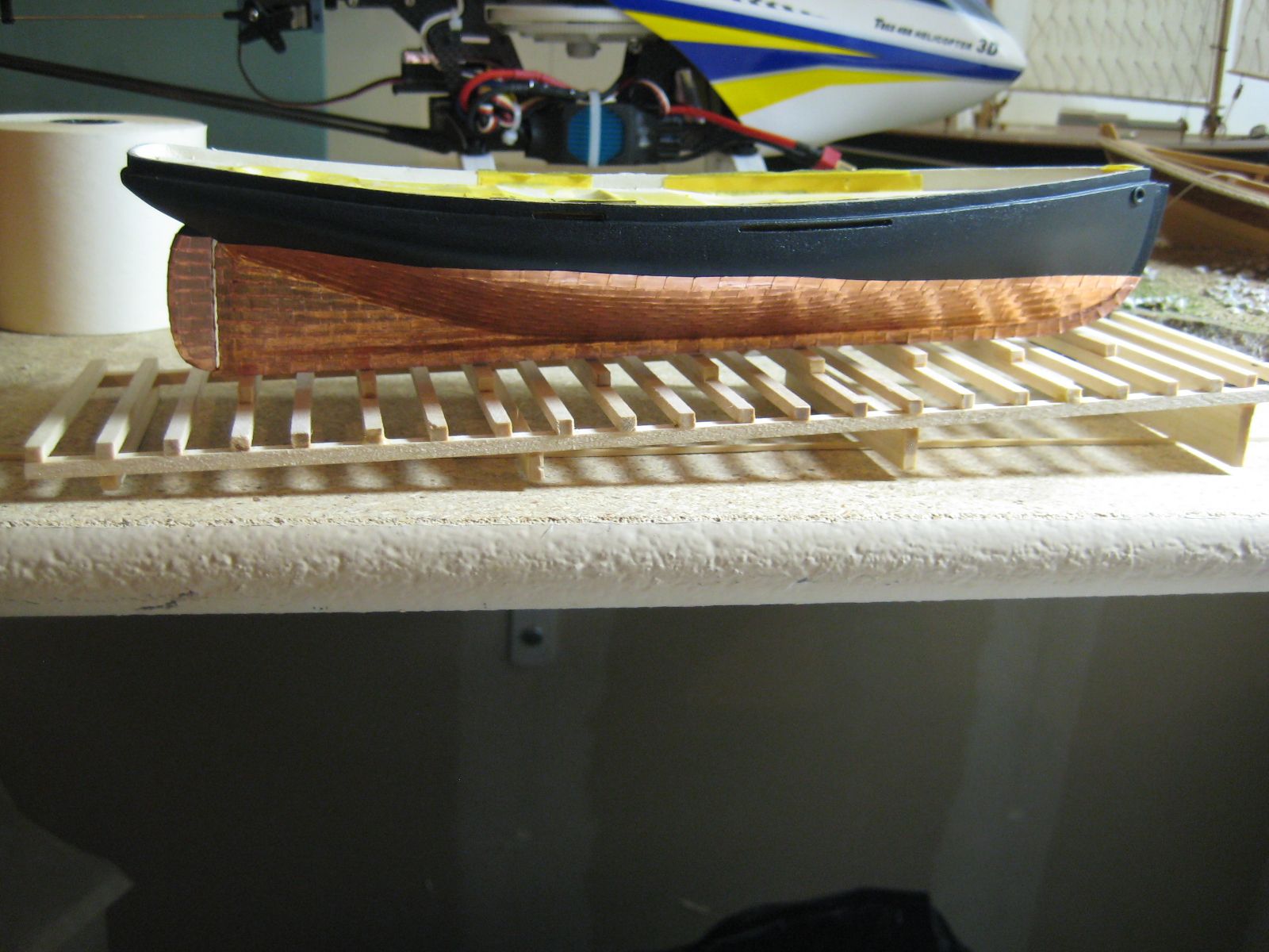
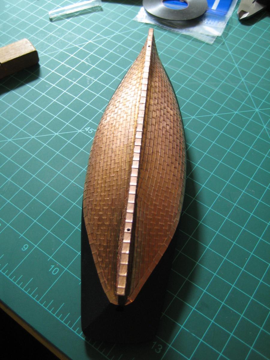
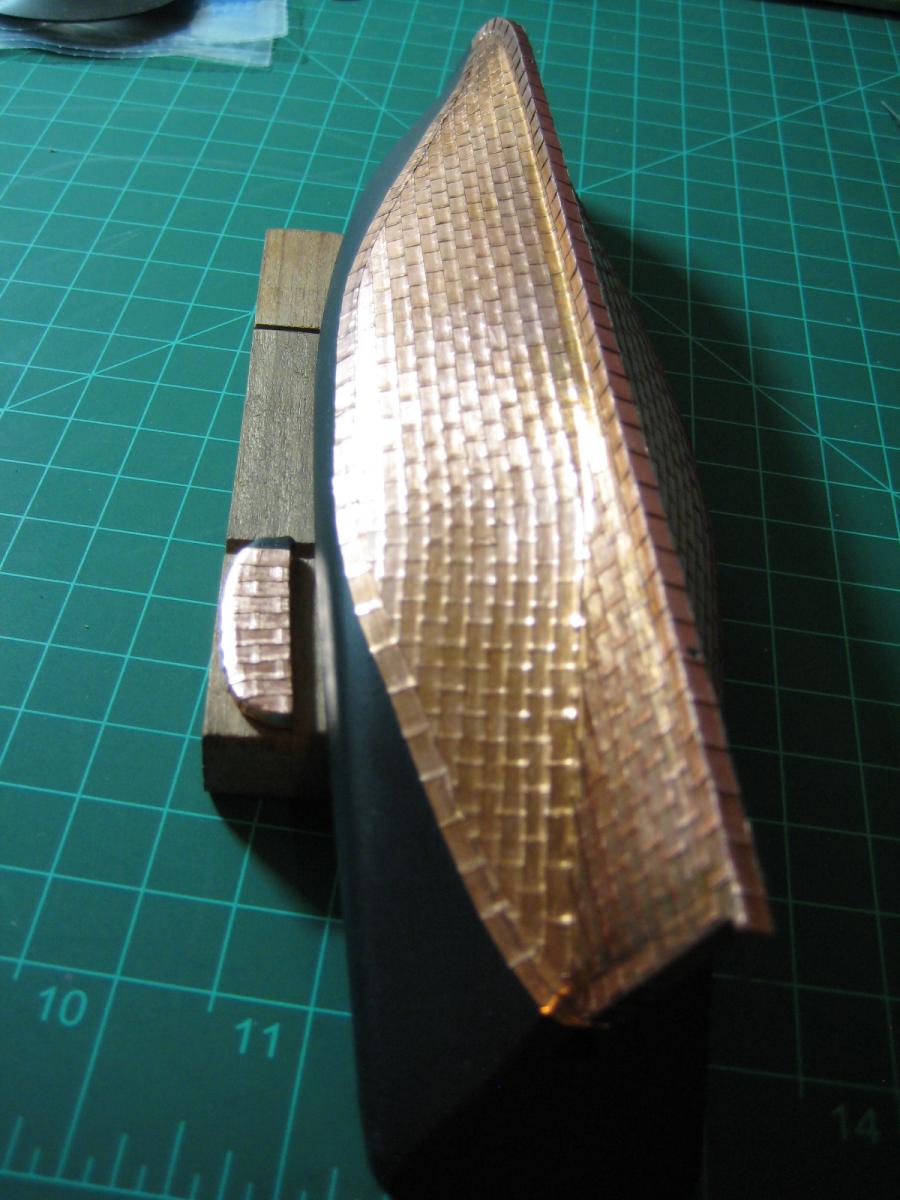
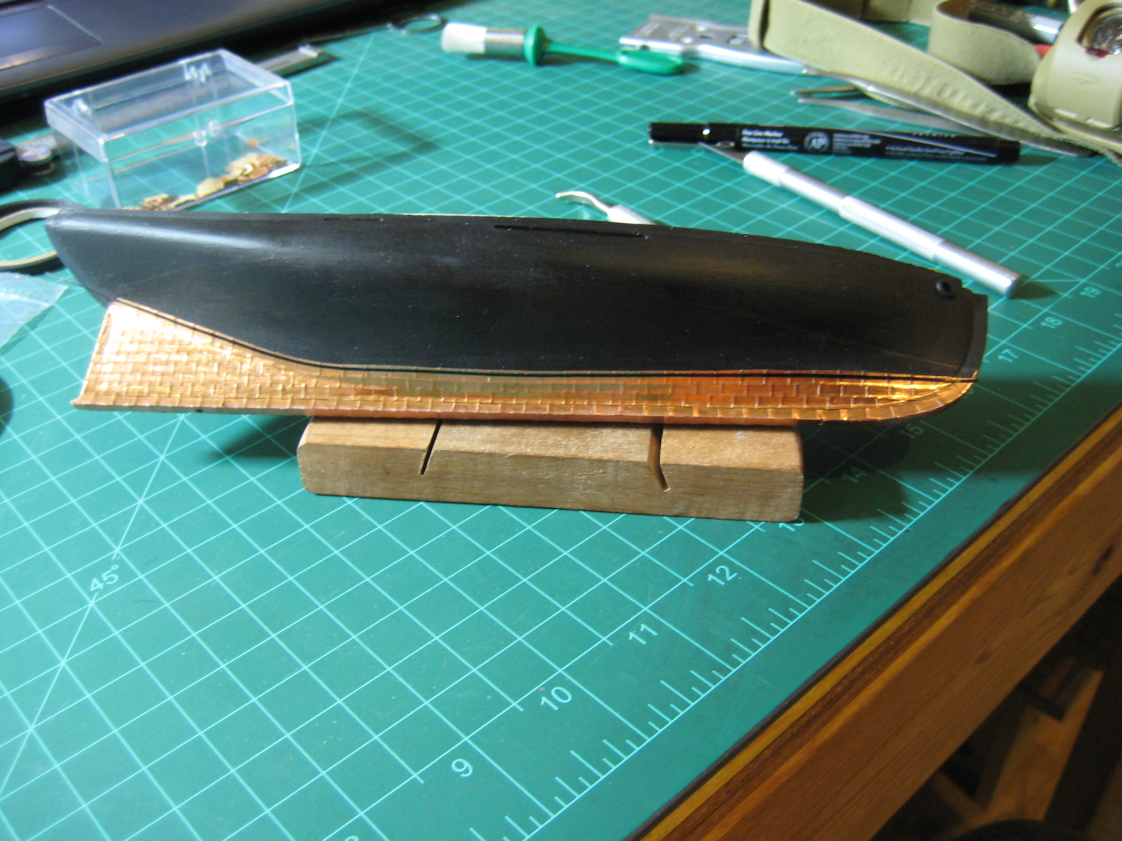
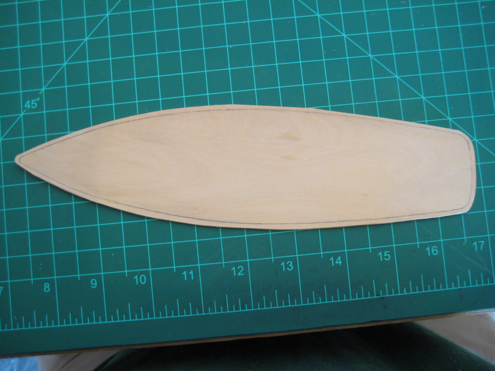
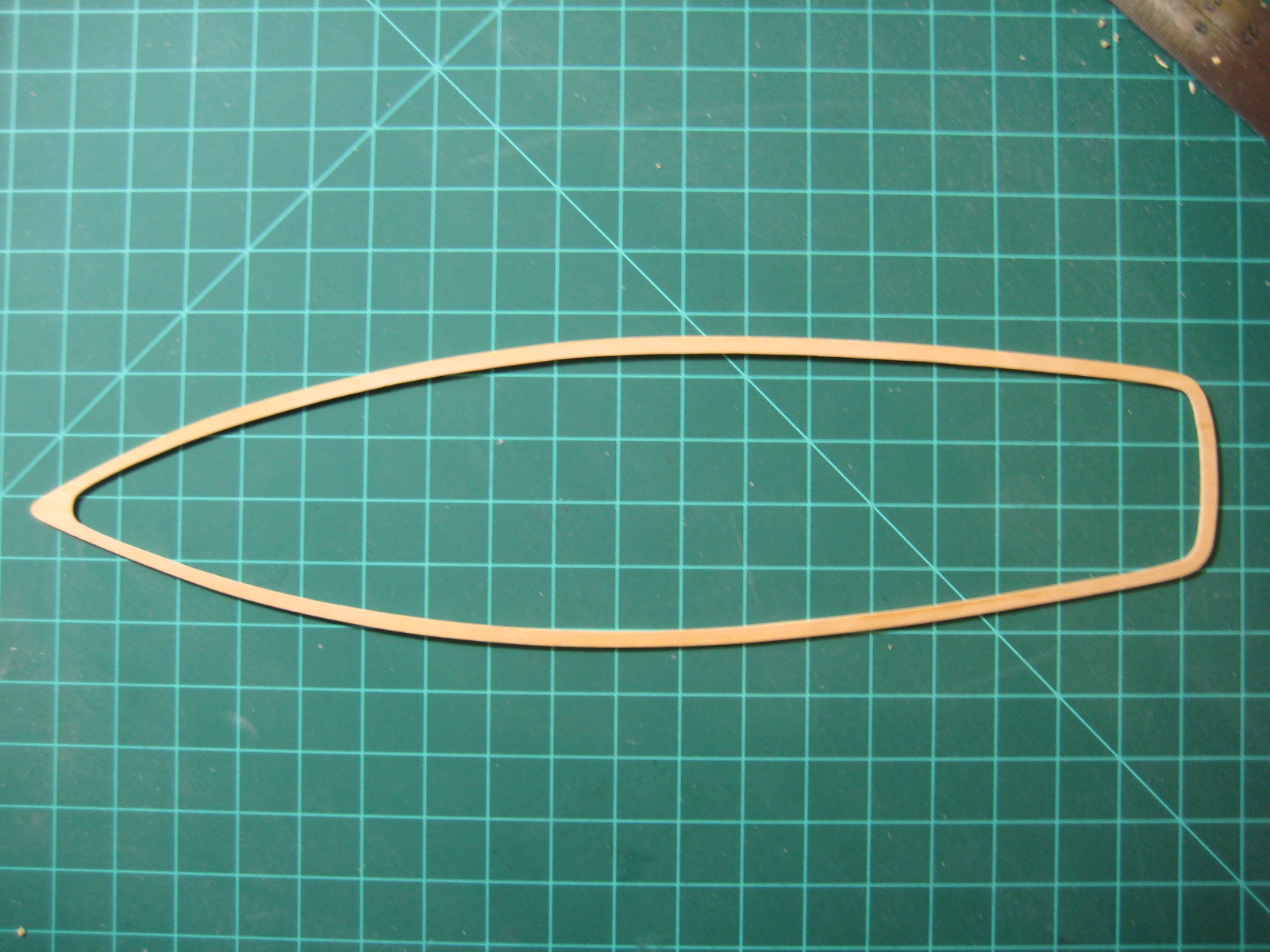
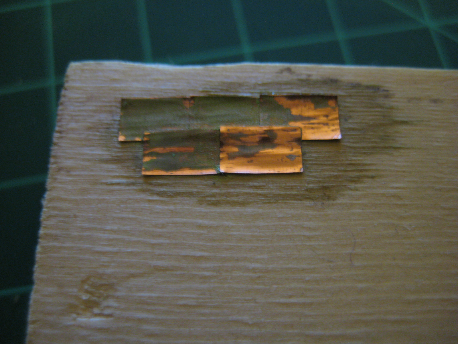
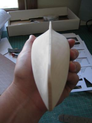
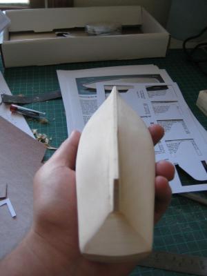
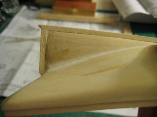
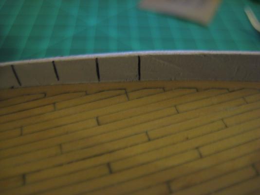
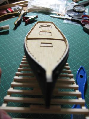
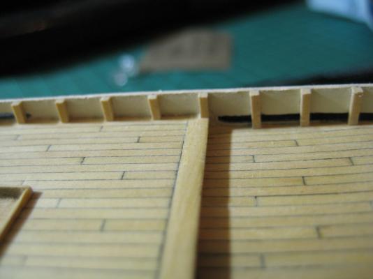
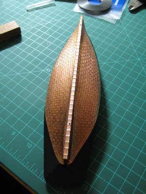
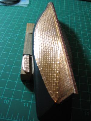
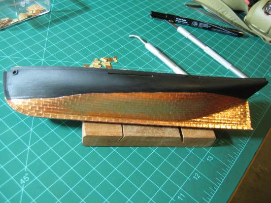
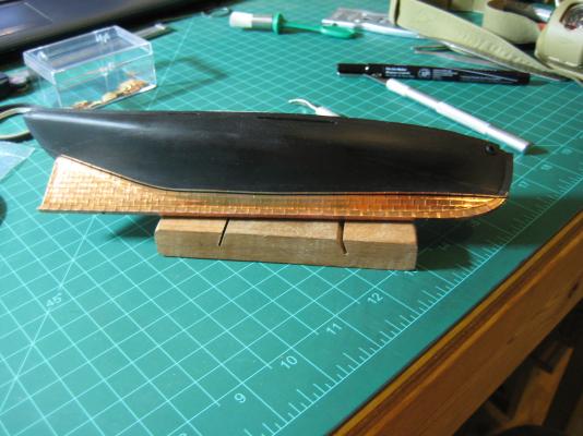
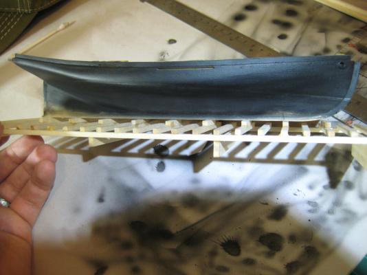
Gulf, I found that following the templates turns out a nice shape. The templates for amid ship pretty much don't have you thin that area down at all, maybe 1mm to 2mm (just guessing there). Once you get to the area of the hull leading to the sternpost area, that is where you begin to thin down to the 1/8" thickness pretty far. Here are some pics to show what I mean. Here is a photo of the thinned keel from the bow before the false keel was installed. And from the stern. You can see here that the thinned area extends down much further at this end of the hull. Now here is one from the side showing the sternpost area where the thinned part extends down. Now one with the hull being coppered. the first plate on the bottom covers the false keel, then you can see where the thinning ends on the second plate. Here you can see that even if your shaping of the hull is not perfect, the results after you copper can still look nice. Don't mind the waterline on this side of the ship haha. I hope this helps. Let me know if you have any other questions or anything, I will do my best to help.


-
Looking good! Minwax wipe on poly in satin works well also.
-
Interesting article, thanks for sharing.
-
Ditto, happy birthday!
-
Hamilton, thanks for the support, the bulwarks were a little bit tough and I ended up shedding some blood, making a late night trip to the ER and getting my first stitches ever. They better look good! If you are interested, when I was carving out the bulwarks at the aft end of the ship where the grain of wood is not ideal for carving the way that is needed for the bulwarks and the wood gave way and I learned very quickly to make sure the area behind whatever you are working on is clear. I wanted to just use some gap filling CA and call it good but the wife insisted we go to the ER when she saw that there was fat coming out of the wound, probably the right call. lol. Mark, welcome to my build log and thanks for the kind words! Feel free to ask away if you think of any questions, I'll answer to the best of my ability. As for the build, I have been working on carving out a new cap rail since the one I carved out originally did not fit properly and it was not wide enough to cover the bulwark stanchions. It has proven difficult because the wood at the aft end (same area that broke and gave me stitches) keeps breaking and then I have to re-glue it together and make a little more progress before it breaks again. I will post pictures once I finish carving it out. On a side note, I think I underestimated how little time I will have for the next few months to work on this build. Again, I will work on it when I can but my courses will take up most of my time.
-
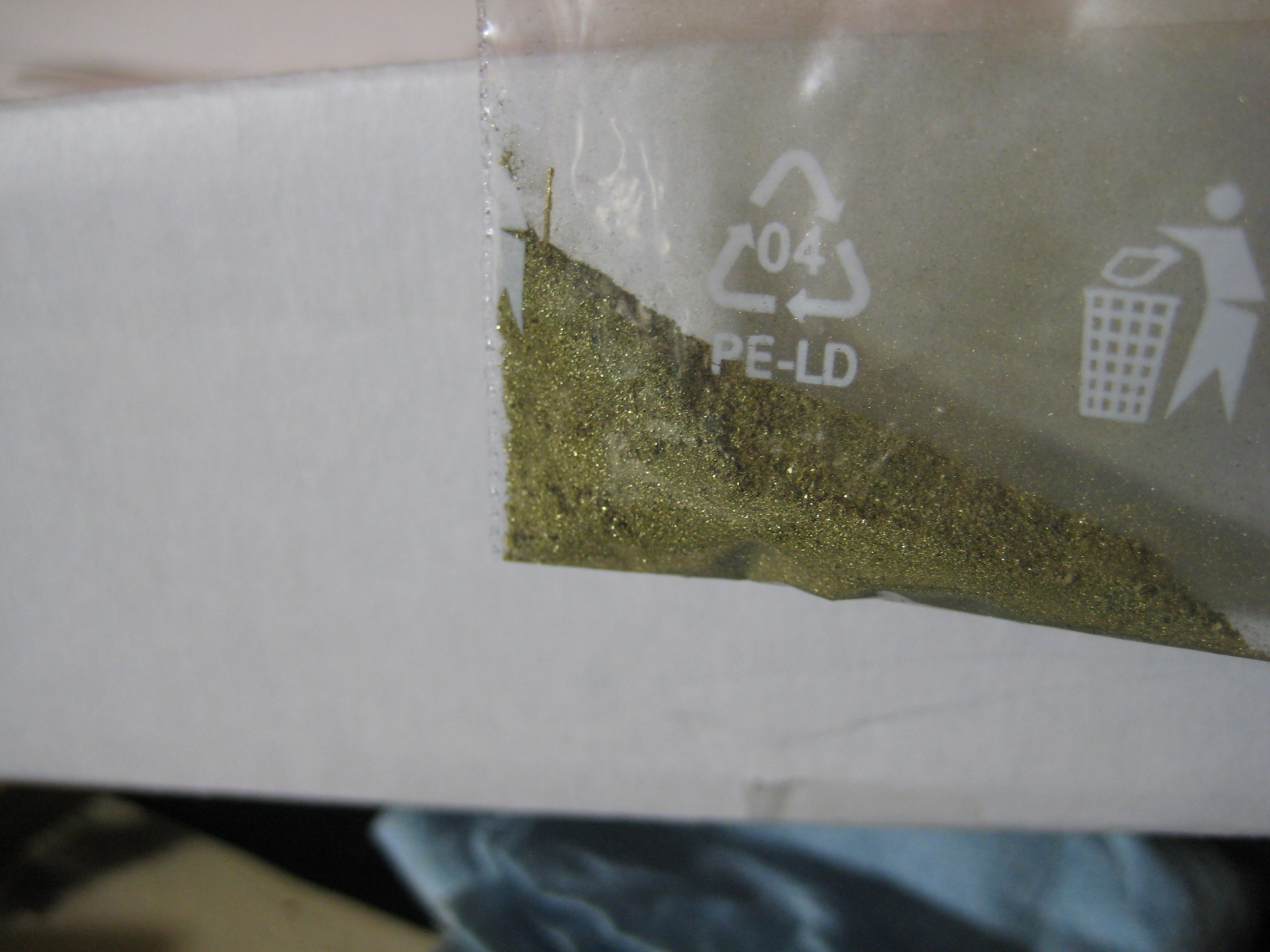
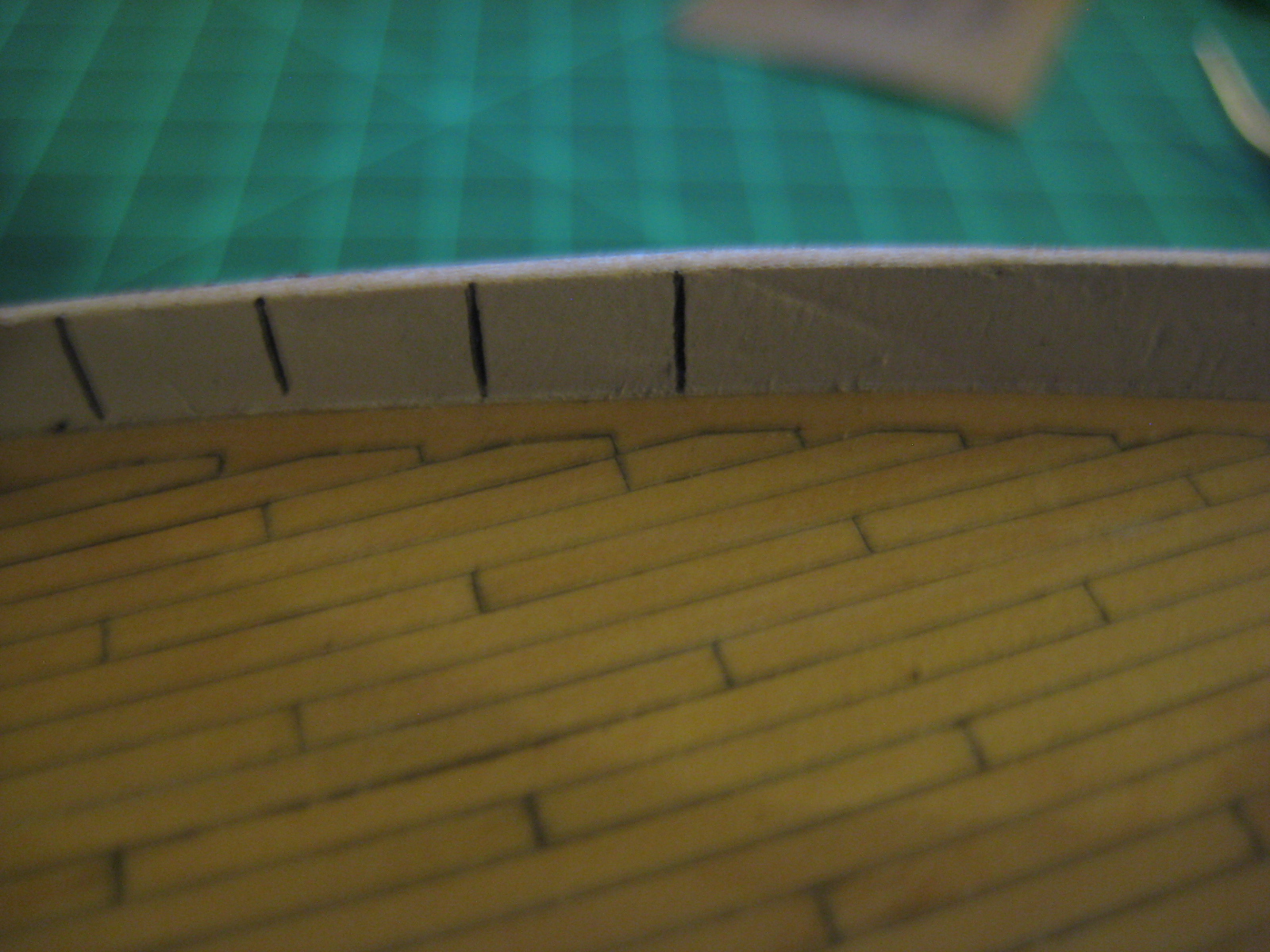
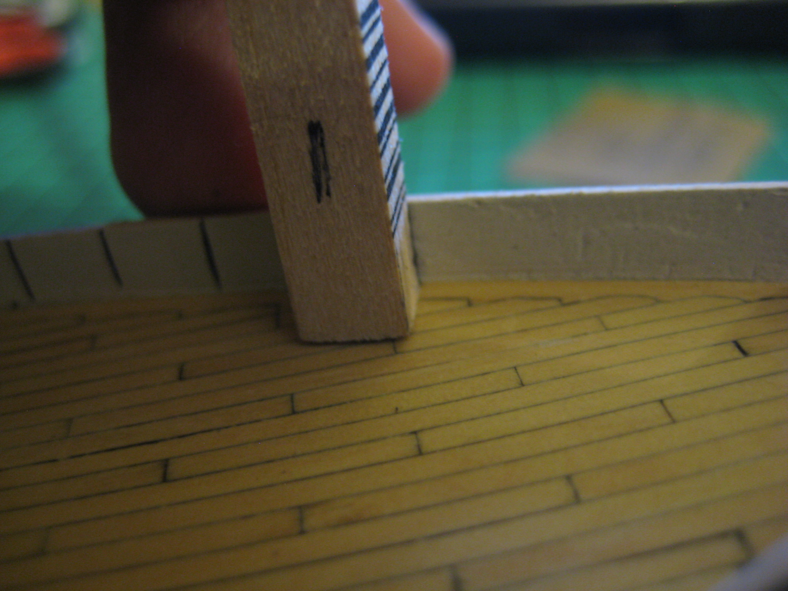
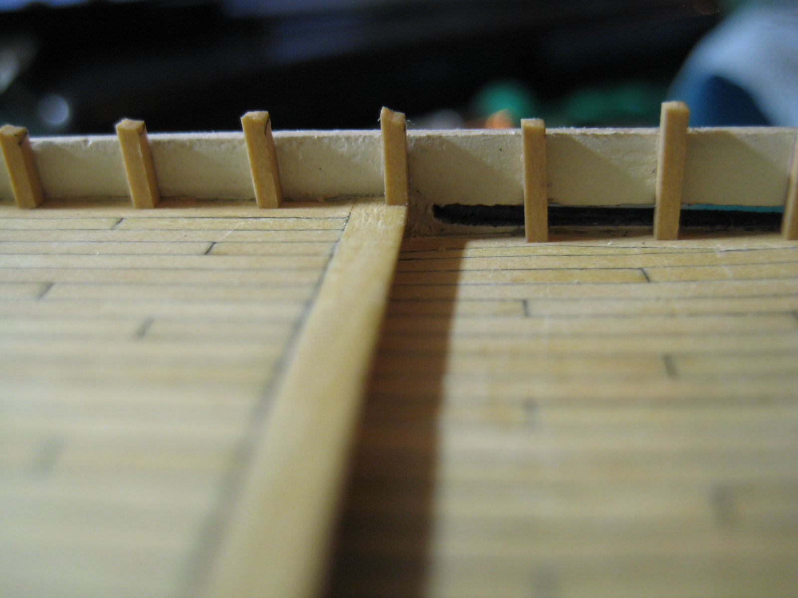
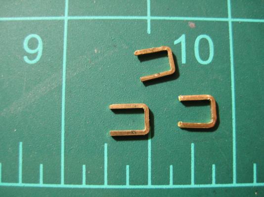
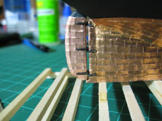
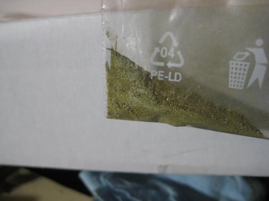
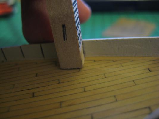
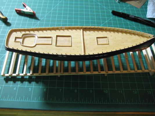
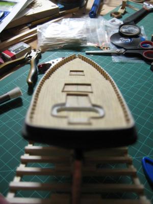
Hey guys, Wayne, thanks for stopping in! I just noticed we have the same quote in our signatures just with different wording, how funny. Hamilton, as I mentioned in my previous post, I am so relieved to have finally finished the coppering and I agree that the build will start to move along at a better pace now. In fact, this update has multiple mini projects which were completed. Update time: This update is a bit picture heavy, sorry. Also, this update is one in which the camera shows every flaw! Anyways, I created the pintles and gudgeons for attaching the rudder and it is now attached. The work of creating and installing the bulwark stanchions is also finished. I cut a strip of brass measuring 1/32" x 1/64" off of a sheet of 1/32" thick brass I had laying around. Then, to create the bends in the material, I clamped about 3/16" in a set of pliers and used my jeweler's hammer to hammer it flat against the flat side of the pliers I was using. Then, just bent the second bend the best I could in the tight space about 1/8" up the strip and snipped off. I was happy to get to use my jeweler's hammer for this because I just picked it up at the IPMS nationals which had something like 20,000 square feet dedicated to vendors and came fairly close to my stomping grounds. On a side note, it was mostly all plastic models in the competition but there were about 5 wooden ship models there as well, one being the MS Niagara which is a ship I will likely build in the future (debating on that being my next project). Back on topic, here are the rudder pintles before being painted and attached. I then painted them black along with the gudgeons and used epoxy to affix it all to the rudder and hull. Chuck used a piece of wire in the hinge but I figured that won't be seen and the epoxy should be more than capable of holding the rudder in place. The full scale measurements of the pintles and gudgeons are 3" tall and 1.5" thick which seemed reasonable to me. Everything in this picture looks horrendous! Once I saw the picture I looked very closely and decided I may do a little touch up of the paint but most of the flaws are not noticeable to the naked eye and it definitely passes the 5-foot test as it stands now. When I was cutting the brass strip, it created a bunch of brass dust which I thought I would save for a future project maybe to be used as gold inside a chest or something. I don't know for sure if it will prove to be of any use but I really did think it looked a lot like gold lol. Next, the bulwark stanchions. I took pictures every step of the way except for ripping the strip of wood I used for them, so there are a lot of pictures here. First, I marked the locations where the bulwark stanchions will be by using a strip of 1/4" square basswood and a sharpie. I must have screwed up a little bit on the rear quarterdecks because one side has one more than the other. No big deal but I thought I would mention it. Next, I cut small lengths of wood from the 3/64" square strip of boxwood I ripped from a 3/64" thick sheet. These dimensions are from Chuck's practicum where he calls for 1.2mm wood and these are about 1.15mm, pretty close. Following Chuck's instructions, I made each one a little too long. Next, each one was filed down to be flush with the top of the bulwarks. Here are a couple pictures of the bulwark stanchions installed from both the bow and stern of the ship. Now on to installing the cap rail, bulwark details like cleats and eye bolts, fabricating the splash rail and fairleads, and then drilling the mast holes. I like when there are a bunch of small projects to work on, it makes the build more enjoyable for me. See you next time!

-
Hey guys, Alas, the copper plating is finished! It is such a relief to have finally finished that project. I think it looks passable but there is definite room for improvement. I give the guys who do a great copper job all the credit in the world, wow. Anyway, here are the pictures of the finished project. Im not sure what happened to the waterline on this side. The line had faded almost completely but I thought I could make it out, apparently not. The port side waterline came out a bit better, still not perfect though. Well, I am super happy to be done with this portion of the build. Next will be installing the rudder, cutting and installing the bulwark stanchions, and then the cap rail, bowsprit and the small details around deck level. The build should be picking up in productivity, which will be nice considering I will have much less time for the next few months. Until next time,

-
Hey guys, Popping in with a quick update. First, replying to posts. Tom, I haven't had too much trouble getting the paper off the backs of the plates, I find that most of the plates have a small separation somewhere on its perimeter where I can get my tweezers in. Your way may be easier or more efficient but I have already cut most of my plates, I might need to do one more batch of plates to finish up the copper job. Sam, As always, I am doing my best. This process is slow and difficult to get just right. But I'm getting through it and its turning out alright. Now for the update: I have been working long and hard on knocking this copper job out. It is very slow, mind numbing work. It should be done in the next few days and it should definitely be done before my personal deadline of next Monday when classes start back up. That reminds me, with classes gearing up, I may not have much time to work this semester as it is looking like a very difficult and time consuming semester. I will get in some building where I can though! As for the copper job, I have finally completed the port side of the hull with the exception of the final band at the waterline. I am going to hold off on the final band until both sides are done and I can do a quick touch-up of the hull's paint. At this point, what's one more coat? haha. A pic of the port side pretty much completed. I have been using Chartpak graphic tape to line up the plates. It works like a charm to get everything pretty even; All you need to do is burnish the plates up to the tape and that's it. I found that technique in someone else's build log a while back but I can't recall whose, just know that it is not an original idea. At first, I was only able to find 1/8" which worked decent but it was a little hard to get it properly lined up. I recently found some 1/32" and 1/64" tape at a local art supply store and they work much better. I prefer the 1/32" out of the two and that is what is pictured below. Let me know what you guys think. It is far from perfect but it is coming along.
-
So I just have to out my two cents in on the beer issue, if we are talking about Colorado beer can we go with some New Belgium beer like fat tire or 1554 please? Hell, I would even take craft blue moon from coors field! Jay, are you going to the IPMS Nationals in Loveland this weekend? If nothing else, it will be a gigantic hobby shop to peruse and they will be having seminars on models building techniques.
-
Sam, Like Yves said, it doesn't look to bad as a start. I am interested in seeing how she turns out and the improvements you make on her. Good luck and I will be following along!
-
So here is where everything stands for now. I ordered and just received the inexpensive drill press from Rio Grande, Thanks for that recommendation! It is kinda a cheap chinese drill press but it seems to have little vibration or bit wobble so it will serve my purposes. I am building a DIY lathe with an $18 hand drill I picked up at Harbor Freight which will be used to shape masts and spars for this build as well as future builds until I can get a proper lathe for scratch building down the line... maybe it will be a christmas present from the admiral. I have needed a mini table saw more than a couple times during this build and am sure that requirement won't be going anywhere in future builds, especially once I move over to scratch. It seems like there are so many uses for a table saw other than just ripping planks and whatnot, I have already made a scale grate for my current model as well as cut a new strip of wood for the bowsprit among other little things, and that was all with a DIY dremel table saw project I made. It has served its purpose but a proper saw like the JimSaw would do a much better job and make it a much faster and less painful experience(Not actually painful, but emotionally painful at times... lol). The draw plate is not something I have needed yet but I am sure I will use it in the future and it is so inexpensive to just add to an order of other tools. The disc sander would have made my life soo much easier on this build and I am sure it will continue to prove useful in the future. I am very excited for this tool. I also really want the thickness sander but that will wait until scratch building is closer and I can convince the admiral on that tool. And about keeping the admiral happy, we are planning a vacation to Mexico for early next year which will give us both something to look forward to and keep us both happy in the months to come. Again, thanks for all the recommendations!
-
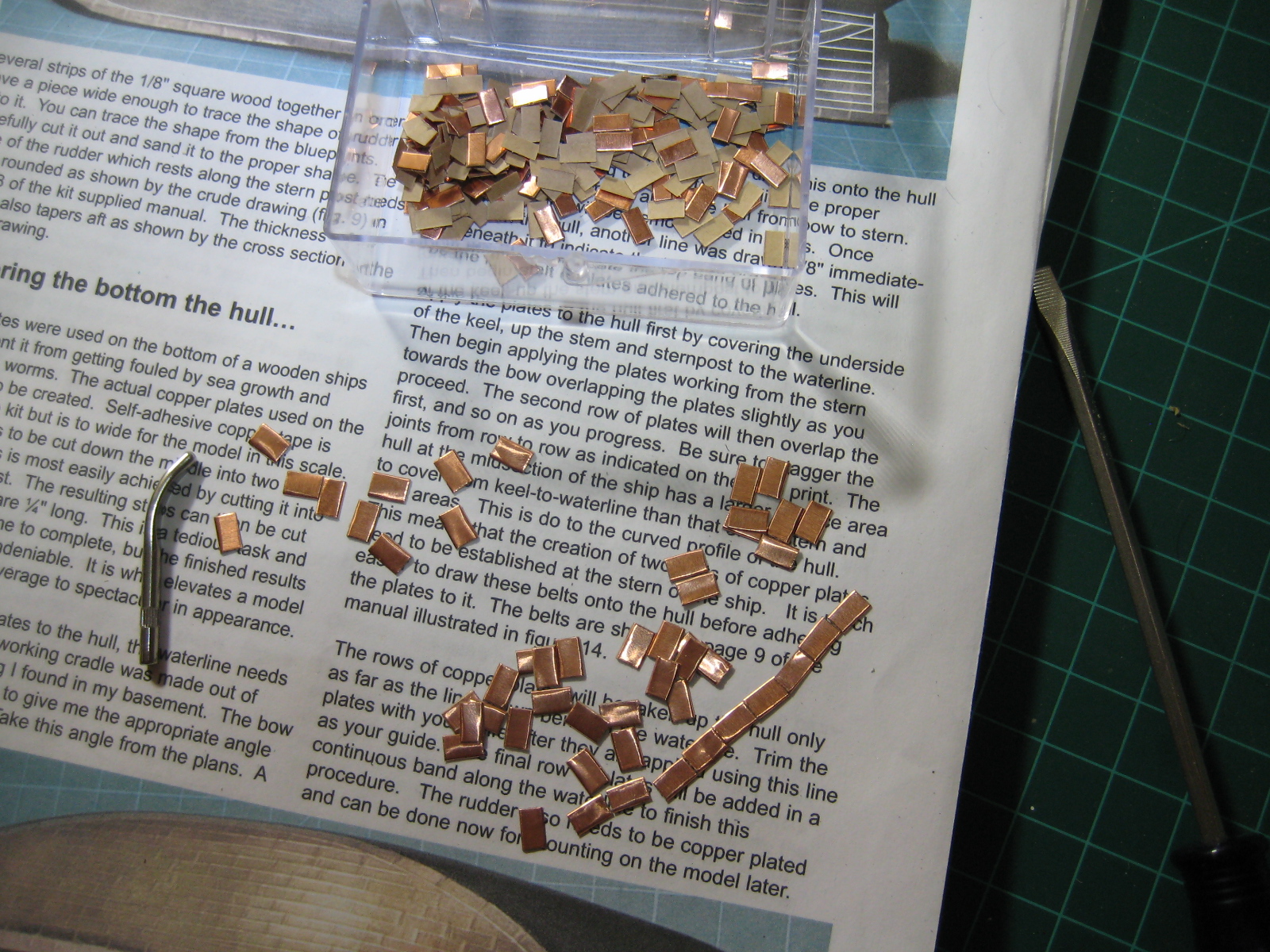
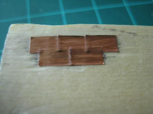
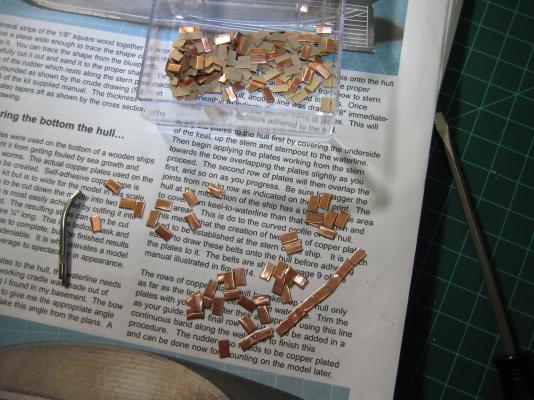
For anyone interested in the little jig I am using to cut the copper tape into plates, here it is. This is not an original idea, I got the idea from more than one other build logs, SteveM's comes to mind but I am not 100% sure that is where I got it. Pretty simple, Chuck's practicum tells you to cut the 1/4" tape into two strips of 1/8" strips and cut 1/4" lengths from those. That seems like it introduces more opportunity for human error to compound and produce a sub par product(in my newbie hands at least). The solution? Cut 1/8" pieces from the already sized 1/4" wide tape. I can see that Chuck's method would produce plates with one perfectly straight side length wise for all the plates which would be nice but this method seems to produce acceptable plates. Here are the pictures: Rinse and repeat about 1,500 times and you're done!


-
Hamilton, you are right, I have discovered that Pandora is my friend for this process! lol Gulfmedic, I understand about life taking priority. I had to put my build on hold for about 6 months or so and am now just getting back to it, no worries, she will be there when you have time for her. One lesson I learned from one of the more experienced members on MSW 1.0 was to treat every little step as a project of its own. That way, you will be completing lots of little projects and feel some accomplishment AND once you finish your model in that manner, you will have a much better looking model than if you just rush to finish her. Thanks for the support, sometimes I feel like I am WAY too long winded. The Dremel table saw is quite useful, I am still planning on upgrading to a Byrnes saw, hopefully soon, but this DIY one has proven its worth already. One thing of note, you may want to make it a little bit taller because with the dremel 4000 at least, the cord hangs down further than the surface the table saw is sitting on. Just something to keep in mind.
-
Sam, thank you. I am doing my best on this model to see where my skills were when I got into this hobby and I figure it will give me a great reference down the line once I build my skill set and am doing that 100 gunner you speak of. Gulfmedic, so far I have only been using the plans, Chuck's practicum, and what I remember from all the old build logs on the original MSW. I tried finding information on this ship when I first got the kit but had very limited success. The other big thing is just thinking about things before building them. I try and think of the scale and figure out what would make sense full scale first. For instance, the deck houses' roof planking and the foootboards that go around them are all 1/64" thick. I had a bunch of 1/32" thick strips of wood but when I thought about it, I realized that would mean they would all be 3" at full scale which seemed awfully thick in my mind. So I made a little jig and thinned the strips down to 1/64" so that they would be 1.5" at full scale which still might be slightly oversized but it is definitely closer to the right size. By the way, glad to see you back around these parts again. Your Phantom build is off to a great start, do you see any time to work on her in the near future? If you have any other questions, ask away, I am always willing to help where I can. Adam, I figured that it would change a bit over time but haven't really seen many pictures of what it looks like. If you have them, would you mind uploading a couple pics, maybe one from around when you first built her and another from now so we can see the difference? Don't go out of your way, but if you have them, I would love to see them. I have come to the conclusion that the 100% Patina-It is way to concentrated for this application, I might play around with some diluted solutions to see if I get a more desirable result. Update: As for the build, this coppering business is very slow going, I think it is going to take a while to finish up, I have been spending a LOT of time working on it and just don't make much progress. I also started building a homemade hand drill lathe that I plan to use later in this build once I get to shaping the masts and spars. I basically started that project to break the monotony of coppering haha. I am also trying to find some suitable material and a good technique for doing the masts as I am leaning toward adding them to this project to fill in the upper area of the model. In my mind, the models with very complex rigging look nice with or without the sails but I feel like there will be something to be desired with this model if I don't add them.
-
Hamilton, this is my first ever attempt at coppering but it is proving to be tedious as you said. It is taking forever and I only have the bottom of the keel and one side of the keel done(the first row on the side of the keel, not one half of the hull being coppered) and am working on the other. Like yours, my kit came supplied with a roll of 1/4" wide copper tape which I am then using a small jig to cut 1/8" long pieces off of. I will post a picture of this when I start cutting more plates. Are you currently coppering a hull or are you already done?
-
Hey guys, Thanks for all the responses! The wife has already signed on to make me some sails, hopefully they will turn out really nice. I am trying to find some material that will look good on my current build which is 1/96 scale. She has also gotten a kick out of this thread, though Pompey2 is in the dog house! As for the tools, I think I might go ahead and pull the trigger on some Byrnes tools, specifically the table saw, disc sander, and drawplate come next month. I might also go ahead and pick up the table top drill press from Rio Grande as that seems like it would be a helpful addition to my workshop and be a little more precise than the dremel workstation I currently have. Still not set in stone but thats kinda what I am leaning towards. I would love to get a lathe but maybe I will just build a hand drill lathe for the masts and spars and buy an actual lathe later on down the road. Same with the thickness sander and bandsaw, those can wait until I decide to start scratch building.
-
Thanks for the responses! Those links really helped, just out of curiosity, what do you guys recommend as to the size of nozzle? Are all the needles the same than the only thing that changes is the nozzle? I am very new to this and don't know how it all works. Also, what are the different benefits of going with .5mm or .35mm ect?
-
Hey guys, First, responses to your posts. Adam, ever since I first opened the kit to see the contents, that grating has bothered me so I am glad I was able to make something I can live with as a replacement. Too bad I don't have a Byrnes saw yet, as it would have come out much nicer I am sure. Hamilton, as always, thanks for the kind words and encouragement! That totally makes sense to just focus on building some skills with your first kit, I built a few Midwest kits before starting this one which really gave me some confidence to go ahead with this build. I am sure this build would go MUCH faster if I wasn't trying to improvise so much, hopefully it all pays off in the end! It has been a while since my last update so here is a quick one. I have been working on a variety of little items for the ship: I cut the caprail, I am working on the rails for the sliding tops of the companionways, I have been cutting a TON of copper plates, and started experimenting with Patina-It. Oh, and I almost forgot to mention why the updates haven't really been coming. I have been experimenting and practicing with my new airbrush and I finally built up the confidence to paint the hull and inside bulwarks with it. I have found out first hand that spraying acrylics definitely has its fair share of difficulties like tip dry and whatnot. Fun to practice though! Here are a couple pics of the caprail. I started with a 1/32" thick sheet of boxwood, pressed it against the bulwarks and traced the outside. I then cut out about 1/16"-1/8" wide of that line and sanded to shape. Once it roughly overhung the exterior of the bulwarks by 1/16"-1/32", I cut out the interior and went to work with my needle files until it was about right. I am a little concerned that I didn't leave enough overhang on the interior to fully cover and hang over the stanchions but that can probably be fixed by sanding them a little thinner. A picture of the hull exterior with two coats of Golden fluid acrylic bone black with matte medium and airbrush medium mixed in. The waterline is also drawn on. 250 copper plates in the box and some oversized plates for the keel, stem, and stern post. A few spare copper plates on a scrap piece of wood, burnished and ready for patina experimentation. First try using Patina-It. I used some 0000 steel wool to remove the finish and then applied two coats of Patina-It with this result. I will be trying many different methods of application and see if anything seems like it will look good on the model. Maybe a more sporadic application so it isn't as solid. Let me know if you guys have any experience or ideas about using this stuff. Now it is on to coppering the hull and I expect this project to really start moving along.


-
Hey guys, I recently aquired a used Iwata HP-C airbrush which seems to have been discontinued a few years back and was replaced by the HP-C Plus. I have no idea what size nozzle or pin it has in it but I am thinking I probably should get a new set of at least a .5mm nozzle ect because I am having some trouble spraying the Golden fluid acrylics thinned with Golden airbrush medium. Does anyone know where I can get these parts? Are they standard over all Iwata brushes? If not, will the HP-C Plus parts work in my brush? Thanks for the help guys, I am brand new to airbrushing and trying to figure this all out.