


Elia
-
Posts
548 -
Joined
-
Last visited
Reputation Activity
-

 Elia reacted to Leo-zd in Yacht America by Leo-zd - FINISHED - 1:200
I think that nobody on this forum need the presentation of the original, of "the mother of regatta's boats" the .
Maybe the best description was the dialogue between the Queen and the Commodore oduring the regatta around the Isle of Wight, August, 22, 1851:
Queen Victoria: Who is the first,
Commodore:"America, your Majesty."
Queen Victoria: Who is the second,
Commodore:"There is no second, your Majesty."
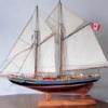
As the other models, in small scale 1:200, reduced Mamoli drawings in 1:66 , in fact i had the complete kit, i made it an the big one was a marriage gift for one cousin
The model was made with complete double planking, second planking with walnut 1*1mm, the deck is also some light wood, strips 1*1mm.
As in that time (before internet) I hadn't to many references, but honestly I didn't searched to much, i decided to put the table (improbable elliptic shape 😕 ) in the "salon" undo the big windowed portion, then on the table put the chart , square/triangle and the other "useful" parts )
Honestly I was convinced that it could't be visible, which is right, without lens you could't see nothing but some colored, a bit bigger, dust
On all models so on this on the keel I made two small holes and put inside pieces of small piles (part of medic needles or similar ) so for the support later i use small profiles with pieces of steel rods fitting in that pipes. The rods are slightly curved so for put in or out is needed some force, nothing extra but enough to hold firmly together the support and the model with simply possibility to separate.
On the last photo are the three models, Flying Fish and America in 1:200 and Shenandoah in 1:100
as a comparison of dimensions
Also in this model is evident the out scale of elements but I hadn't the patience nor the materials and tools to made it in scale.
To finish the model I have to arrange the rigging and the sails which I usually make from the paper which could be find inside shoes or cloth boxes, also the support has to be made.
-
 Elia got a reaction from newbuilder101 in San Felipe by newbuilder101 (Sherry) – Scale 1:96
Sherry,
It is great to see another update on your build, and those cannon look great! As one who doesn't own a lathe and has to find alternative processes and materials to what typically would be lathe turnings, i appreciate and applaud your extremely sharp looking 'mixed medium' cannons. Well done!
Cheers
Elia
-
 Elia got a reaction from Dimitris71 in Arethusa 1907 by Elia - Knockabout Banks Fishing Schooner
Hi Lawerence,
Thank you very much for the compliments. I look forward to seeing your Annie take shape. It looks like a beauty of a ship that will be quite attractive as a model. I thoroughly enjoyed building up the hull and planking my model. While there is a decent amount of spiling to the hull planks, these fishermen have such attractive hull shapes once planked. And there is actually quite a bit of variety inthe shapes - plumb stems, spoon bows, Fredonia hulls, sharpshooter and clipper bows, deep and shallow draft hulls, not to mention jib booms, pole bowsprits, semi-knockabouts, and knockabout rigs...
With the cold winter weather upon us my basement shop, my man cave, with the emphasis on "cave", is quite uncomfortable for modeling so right now I'm slowly puttering on the masts and spars. I built a dory I intend to use as a master and cast a bunch of them...but that is progressing slowly too.
Cheers
Elia
-
 Elia got a reaction from Rustyj in Arethusa 1907 by Elia - Knockabout Banks Fishing Schooner
Hi Lawerence,
Thank you very much for the compliments. I look forward to seeing your Annie take shape. It looks like a beauty of a ship that will be quite attractive as a model. I thoroughly enjoyed building up the hull and planking my model. While there is a decent amount of spiling to the hull planks, these fishermen have such attractive hull shapes once planked. And there is actually quite a bit of variety inthe shapes - plumb stems, spoon bows, Fredonia hulls, sharpshooter and clipper bows, deep and shallow draft hulls, not to mention jib booms, pole bowsprits, semi-knockabouts, and knockabout rigs...
With the cold winter weather upon us my basement shop, my man cave, with the emphasis on "cave", is quite uncomfortable for modeling so right now I'm slowly puttering on the masts and spars. I built a dory I intend to use as a master and cast a bunch of them...but that is progressing slowly too.
Cheers
Elia
-
Elia reacted to newbuilder101 in San Felipe by newbuilder101 (Sherry) – Scale 1:96
Thank-you everyone for all the comments!
Well, an update is long overdue - I almost feel I should introduce myself again!
I struggled in the summer with which route to take for my cannons. I tried making molds and casting with resin with only limited success. The summer flew by and winter appeared and casting became a problem due to mess and allergies, or at least some reaction to the fumes. Ideally working outside is the best option, but at -20 degrees Celsius, it's not an option!
I had seen some paper cannons that Doris made and I thought I would give that a try. It would be easier if my scale was larger, but I don't find it too difficult. I know they are not perfect, but I am relatively pleased with the outcome and will continue with this process.
I am currently experimenting with weathering the cannons, so the painted one is not necessarily what the finished product will look like.
-
 Elia got a reaction from canoe21 in Arethusa 1907 by Elia - Knockabout Banks Fishing Schooner
Hi Lawerence,
Thank you very much for the compliments. I look forward to seeing your Annie take shape. It looks like a beauty of a ship that will be quite attractive as a model. I thoroughly enjoyed building up the hull and planking my model. While there is a decent amount of spiling to the hull planks, these fishermen have such attractive hull shapes once planked. And there is actually quite a bit of variety inthe shapes - plumb stems, spoon bows, Fredonia hulls, sharpshooter and clipper bows, deep and shallow draft hulls, not to mention jib booms, pole bowsprits, semi-knockabouts, and knockabout rigs...
With the cold winter weather upon us my basement shop, my man cave, with the emphasis on "cave", is quite uncomfortable for modeling so right now I'm slowly puttering on the masts and spars. I built a dory I intend to use as a master and cast a bunch of them...but that is progressing slowly too.
Cheers
Elia
-
Elia reacted to Omega1234 in Rainbow by Omega1234 - FINISHED - J-Class Racing Yacht
Hi Elia. Many thanks for the compliment, but trust me, your work is on a whole level higher than mine.
Seeing as I'm painting the hull, I wasn't concerned about scale width planks; therefore, the widest planks were two millimeters, whilst the thinnest were slightly less than half a millimeter.
Hope this helps!
All the best
Patrick
-
 Elia got a reaction from Omega1234 in Rainbow by Omega1234 - FINISHED - J-Class Racing Yacht
Beautiful. And always amazing to see. My recent dory (1/48 scale) is about the same length, three planks per side, and your tiny J class looks so so much better. Impressive.
Patrick, how wide are those planks at their widest point?
Cheers
Elia
-
Elia reacted to Omega1234 in Rainbow by Omega1234 - FINISHED - J-Class Racing Yacht
Hi everyone
Well, as promised, here are the latest photos of Rainbow's hull. She has emerged from the temporary frame jig in all her fragile glory. There's still a lot of sanding and filling to patch up the little inevitable hollows that occur when planking, but, it's a milestone to have released the hull from the jig. The simulated internal ribbing will also need to be added...monotonous job it may be, but necessary to ensure some degree of structural rigidity.
I've also made a temporary work stand to hold her from this point on.
Hope you enjoy the photos.
Cheers
Patrick
-
Elia got a reaction from Omega1234 in Arethusa 1907 by Elia - Knockabout Banks Fishing Schooner
Hi Dimitris,
Thank you for the compliment, for the 'likes', and for stopping in on Arethusa. I work slowly these days, enough so that you could take another long break from MSW and still catch up with my progess again.
Cheers,
Elia
-
 Elia got a reaction from PeteB in Arethusa 1907 by Elia - Knockabout Banks Fishing Schooner
Rusty, Robert, Druxey, Mark,
Many thanks for popping in here and for the kind words.
Dick (rhcronan),
While I've been puttering along with my rails I took a little side excursion and snapped some pictures of (a) Eric Ronnberg Jr.'s Arethusa model photo reproductions he had provided to me, and (b )some of the sketches I had made early one in my Arethusa build. Here are forum sized images of them. I think they should help illustrate the stem ironwork on a knockabout...at least Arethusa. I did the sketches based on H.I. Chapelle's book appendix of American Fishing Schooners, and much of those sketches agree with Eric Ronnberg Jr.'s model quite well. I've included the sketches for both the standing and rugging rigging at the stem (along with the jumbo stay on a post forward of the Samson post). I hope these help you on your Helen B. Thomas model. If you are so interested PM me and we can arrange for my sending you higher resolution images.
Cheers,
Elia
-
Elia got a reaction from PeteB in Arethusa 1907 by Elia - Knockabout Banks Fishing Schooner
...more....
-
Elia got a reaction from PeteB in Arethusa 1907 by Elia - Knockabout Banks Fishing Schooner
the saga continues...
-
Elia got a reaction from PeteB in Arethusa 1907 by Elia - Knockabout Banks Fishing Schooner
continued...
-
Elia reacted to Omega1234 in Rainbow by Omega1234 - FINISHED - J-Class Racing Yacht
Hi everyone
Here's the progress so far. Rainbow's frames have been assembled on her keel and the first plank has been temporarily positioned to check the sheer line. I've taken care to ensure that the frames have been waxed to stop them sticking to the planks. That way, if all goes according to plan, I should be able to lift the hull off the temporary frames without any problems.
Here're the photos.
All the best
Patrick
-
Elia reacted to Omega1234 in Rainbow by Omega1234 - FINISHED - J-Class Racing Yacht
Hi everyone
Oh no! Not another J Class yacht model? Yes, I say! They are amongst the most beautiful racing machines ever designed...and Rainbow, is no exception.
My model (loosely based on Amati plans) will be fully detailed inside; much the same as my previous models, eg Ingomar. The interior wil be viewable via an open deck and large cutaways of the hull.
Hope you can join me on Rainbow's journey!
All the best
Patrick
-
Elia reacted to von stetina in Lightning by von stetina - 1/96 - extreme clipper
Hi guys,
Here are some pics of the upper masts and most of the stays on. She wasn't a lofty ship as launched. The Brits added more when they took delivery, McKay gave her an extra wide rig instead, with the main yard being 95 feet long. I feel that he wanted to get power this way, maybe to minimize heeling as she was a passenger ship. Any of your views on this would be interesting.
Bruce
-
Elia reacted to von stetina in Lightning by von stetina - 1/96 - extreme clipper
Hi Ed,
I've noticed the changes in photos. In MacGregor's Book there are some good photos. YA is there changed to the closer mast doublings done by putting a sort of dogleg to clear the shrouds, and iron mast caps. I don't remember if she had been switched to bullseyes for upper shrouds or not. I have 3 different plans of 3 different ships done by Crothers and the differences are interesting.
I found it at only one small RR business They are the only place I found it in 10 foot bulk packs, everyone sells it by the foot. I'll look up their name and post it later or e mail it you. I found that for Lifghtning I needed more than 9 feet.
Enlarge the case...it really brings home the size of these ships doesn't it. I read somewhere that one could build two 74 gun ships with the timber it took to build some of the big clippers.
Shop foreman shown below. winking.
-
Elia reacted to von stetina in Lightning by von stetina - 1/96 - extreme clipper
A look at the backstays. Originally I had intended to us Conservators wax on all of the rigging. However I found that it didn't lay down fuzz well enough so for the running rigging I switched to beeswax. On the heavier lines of standing rigging the Conservators wax was good, but when used on the finer stuff I wasn't happy.
I keep bumping fingers into the thin lines and they slacken. I was trying deal with the idea of doing some over when I just wiped a finger of, um, spit, down the line. It tightened right up! So now besides being careful I just do this.
I'm not to this point yet but in Wingrove's ship modeling book he says to put the yards on by doing the highest first and working down. Have any of you done this?
-
Elia reacted to von stetina in Lightning by von stetina - 1/96 - extreme clipper
It felt great to finally put on the spreaders. Waiting to put them on until now allowed me to position the length and spread correctly. Putting them on too early could have resulted in a bad fit.
They are made of brass also. Another thing I wanted to mention is the use of bullseyes instead of deadeyes here. This is correct for the period.
Time to spend some time with the wife, I'll post more later.
Bruce
-
Elia reacted to von stetina in Lightning by von stetina - 1/96 - extreme clipper
The spanker boom and gaff rigged in place. Using the correct different sizes of rigging bring on the appearance of reality. Seeing the blocks in place is bringing the ship to life for me. Just as doing the rigging on my oil paintings brings the ship to iofe for me.
I took a piece of brass tubing and ovaled it out to wrap my coils of line around to be put on the belaying pins. A touch of white glue fixed their positions.
OH! I forgot to tell you, the flying jib boom is made of brass. The wooden one would have broken. I kept bumping the brass one. Next ship at 1/8 scale I'll do more of this.
Bruce
-
Elia reacted to von stetina in Lightning by von stetina - 1/96 - extreme clipper
The bow is complete. Notice the different size chain. The chain was difficult to size so that there was no slack. I did this by removing links and adjusting the bullseyes.
I bumped the chain with a finger and it went slack....pre stretch the chain first!
Bruce
-
Elia reacted to von stetina in Lightning by von stetina - 1/96 - extreme clipper
A look at the overall project. It's such a relief to be able to button up my model safely in the temporary case. You might notice that the ship is mounted on it's base at this point. It was time for the stability and safety of being fixed in place. The supports on the side are blackened brass. I experimented with different looks for this and settled on the simplest way. The model will need to be shipped a long way and need this stability.
-
Elia reacted to von stetina in Lightning by von stetina - 1/96 - extreme clipper
As soon as the ratlines are done I will mount the davits and boats. Braces go over this area so I think it's time to put them on. Another thing to catch a finger on...
I have no pictures yet but I'm doing the ratlines. I quickly learned to use tape wrapped around the tweezers to limit the amount they open. They would damage the work when they opened.
For doing work shaping blocks I modified a set of tweezers. A lot of blocks are tiny at this scale. Some smaller than a grain of rice. I'll try to remember to take a picture of them.
All the photos for a bit. I've a brass Fairfield coal drag conveyor and a stock pen to build to bring some money in. It kills me to have to take time off from the Lightning. I'll keep an eye though to reply to anyone.
Bruce
-
Elia reacted to jbelwood in Grand Banks Dory color
Glad I didn't do a build on this one as I had to trash my first attempt and start over. I chose this model
to get my feet wet in building large scale boats but primarily to gain experience in clinker built boats. My
biggest oversight with the dory was not realizing the importance of maintaining the curved bottom (rocker).
The rocker disappeared when I removed the frame from the template too soon. Tried to add the planks
with a totally flat bottom. Obviously lost the required sheer to attach the planks properly.
Anyway, short of trashing what I did, I salvaged the frames, stem, transom and bottom and started afresh.
Now I had to get a couple of sheets of 1/32 basswood. My LHS was out of stock and no longer able to get
more from their supplier, Midwest. Apparently, Midwest no longer offers this. Next called Model Expo. Guess
what, they also cannot get this from Midwest, their supplier. Called Bluejacket and was able to get more.
Thank you Nic.
Rather than ramble on about my frustrations, here are a couple of photos as she looks today. The inside
is stained with MinWax Golden Oak. Nothing else is painted. The oars were build according to plan and took
about an hour each. This is a great teaching experience. Hope to finish the model soon.
John Elwood