
Supplies of the Ship Modeler's Handbook are running out. Get your copy NOW before they are gone! Click on photo to order.
×

Jeronimo
-
Posts
729 -
Joined
-
Last visited
Reputation Activity
-

 Jeronimo reacted to Jadesworld in LE BONHOMME RICHARD by Jeronimo - FINISHED
Hello Karl.
Each time you post photos I am totally amazed on the realism of your build.
Everything and detail is there.
WOW is the only way to discribe this build.
Regards Jade.
-
Jeronimo reacted to AnobiumPunctatum in LE BONHOMME RICHARD by Jeronimo - FINISHED
I hope that I have the possibility to see this fantastic model sometimes in real life.
-
Jeronimo reacted to CaptainSteve in LE BONHOMME RICHARD by Jeronimo - FINISHED
Jeronimo,
I was trying to find the words to describe this magnificent build, but words fail me.
I'm speechless !!
Even though I will probably never venture to the dark-side of modelling (scratch-building), I'll be following along from now on just for the stunning eye-candy.
You are a master-modeller !!
Keep it coming.
-
Jeronimo reacted to Jim Lad in LE BONHOMME RICHARD by Jeronimo - FINISHED
More delightful "eye candy". Thanks very much for the update, Karl!
John
-
Jeronimo reacted to dvm27 in LE BONHOMME RICHARD by Jeronimo - FINISHED
Wonderful work, as always, Karl. Are you cutting the mortises for the carlings with the beams already glued in place or prior to fixing the beams?
-
Jeronimo reacted to jaerschen in LE BONHOMME RICHARD by Jeronimo - FINISHED
I'm speechless at this great work
-
Jeronimo reacted to md1400cs in LE BONHOMME RICHARD by Jeronimo - FINISHED
Karl,
Too perfect to easily comprehend. Stunning
Michael
-
Jeronimo reacted to Erebus and Terror in LE BONHOMME RICHARD by Jeronimo - FINISHED
Truly inspiring work - a work of art.
-
Jeronimo reacted to archjofo in LE BONHOMME RICHARD by Jeronimo - FINISHED
Hello Karl,
Your excellent work inspires me again and again.
The interior is meticulously detailed exactly.
-
 Jeronimo got a reaction from JerryGreening in LE BONHOMME RICHARD by Jeronimo - FINISHED
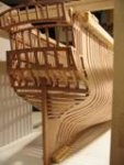
Hello friends,
new pictures of the construction , BHR model.
Karl
T e i l 33
-
 Jeronimo got a reaction from Hannerl in LE BONHOMME RICHARD by Jeronimo - FINISHED
Hello friends,
new pictures of the construction , BHR model.
Karl
T e i l 33
-
Jeronimo got a reaction from JerryGreening in LE BONHOMME RICHARD by Jeronimo - FINISHED
Hello everyone for the kind words and comments.
These are the last pictures of the
LE BONHOMME RICHARD 1779 Part 2.
Regards Karl
T e i l 24
-
 Jeronimo got a reaction from rek in LE BONHOMME RICHARD by Jeronimo - FINISHED
Hello Mark and Gaetan.
Thank you very much.
Karl
-
 Jeronimo got a reaction from Luca in LE BONHOMME RICHARD by Jeronimo - FINISHED
Hello friends,
new pictures of the construction , BHR model.
Karl
T e i l 33
-
Jeronimo got a reaction from JerryGreening in LE BONHOMME RICHARD by Jeronimo - FINISHED
Hello,
assembly of iron knees and
A Hold
5 Shot- locker
6 Pump well
B Orlop-Deck
9 scuttle providing acces to the shot-locker
Karl
T e i l 32
-
 Jeronimo got a reaction from sonicmcdude in LE BONHOMME RICHARD by Jeronimo - FINISHED
Hello friends,
new pictures of the construction , BHR model.
Karl
T e i l 33
-
Jeronimo reacted to archjofo in La Créole 1827 by archjofo - Scale 1/48 - French corvette
Hi Alex,
I am very pleased about your nice comment.
Here is an update of the report:
Completion of the fittings for the carronades.
So now the fittings are manufactured for the carronades. For assembling the brass parts still need to be blacked.
In the following picture you can see almost all the parts to build a Carronade.
All parts are now neatly sorted in a plastic box, ready for final assembly. Thus, over 50 items come together for a Carronade. For 20 carronades which means about 1000 parts.
-
Jeronimo reacted to archjofo in La Créole 1827 by archjofo - Scale 1/48 - French corvette
Hello,
many thanks for your nice comments!
Here are some photos for making the carronades pipe supports.
-
Jeronimo reacted to archjofo in La Créole 1827 by archjofo - Scale 1/48 - French corvette
Hello Friends,
the aligning the carronade was performed with an iron bar.
For this I made the metal fittings.
-
 Jeronimo got a reaction from native one in LE BONHOMME RICHARD by Jeronimo - FINISHED
Hello friends,
new pictures of the construction , BHR model.
Karl
T e i l 33
-
 Jeronimo got a reaction from JerryTodd in LE BONHOMME RICHARD by Jeronimo - FINISHED
Hello friends,
new pictures of the construction , BHR model.
Karl
T e i l 33
-
 Jeronimo got a reaction from Wishmaster in LE BONHOMME RICHARD by Jeronimo - FINISHED
Hello friends,
new pictures of the construction , BHR model.
Karl
T e i l 33
-
Jeronimo reacted to Alex M in HMS Sphynx 1775 by Alex M - Scale 1/48 - English 20-Gun Frigate
Hi guys, thanks you all for warm words!
Nearly nothing time to work at the model, so only a small update. The chains are now completted.
The next task is the bulkheads of cabins, so here the doors under construction. The door windows are done the same way as at the stern, but here I have glued wood strips at both sides of plastic sheet. The images show the making step by step.
Alex
-
Jeronimo reacted to Tarjack in HMY Royal Caroline 1749 by Tarjack - 1:50 - bone model
Hello people,
and once again a story of small things with great effect.
The eye and ring bolts on the gun carriages have brought me to the brink of power capacity.
But now it's done. The fasteners on the gun carriages are ready, now only missing the trunnion straps and rigging
But see for yourself
The eyebolts
The Rings
The Ringbolts
Final assembly
Have fun
-
Jeronimo reacted to Tarjack in HMY Royal Caroline 1749 by Tarjack - 1:50 - bone model
This Eyebolt is the first from 140 Bolt´s i need on the ship
And.......... 40 ring bolts ..... 30 double disc Blocks ..... 30 mono-disk blocks
80 hooks .......... and and and...........so there is no end
Have fun