Jump to content

Jeronimo

Members
  • Posts

    716
  • Joined

  • Last visited

Reputation Activity

  1. Like
    Jeronimo reacted to EdT in HMS Victory by EdT - FINISHED - 1:96 - POB   
    HMS Victory
    1:96 Scratchbuild Project
    Part 16 – Shrouds and Ratlines 


    Shrouds
     
    The shrouds for the Victory model were made from multiple strands of linen, twisted up on the ropemaking machine as described earlier, except for the topgallant mast shrouds, which were too small.  A heavy black mercerized cotton polyester thread was used for these.   All the shrouds are laid up left handed and are four strand if the size could be obtained that way.  If not, three strand rope, though not historic, was used. 
     
    The lower and topmast shrouds are all served over some of their length.  The first shroud in each set was served over its whole length, because of the rubbing it took from the yard and other rigging.  All these shrouds were served where they wrapped around the masthead.  The following picture shows the served portion of shrouds just below the foretop.


    The next picture shows the served shrouds where they are wrapped around the masthead above the top.


    Once served, the shrouds go over the masthead in a specific sequence.  Shrouds are generally paired in twos and after draping around the masthead are lashed together with a seizing.  Some of these lashings can be seen in the above picture.  For appearance sake, care has been taken to place these pairs neatly on top of one another and have them oriented so they do not twist over each other as they descend to there proper deadeye.
     
    Once all the shrouds were lashed into their positions at the top, the next task was to secure deadeyes to their bottom ends.  These needed to be secured at the right length or the deadeyes would not be aligned when the shrouds were pulled tight by their lanyards.  The following sketch, shows how this was accomplished on the model.


    This picture is a composite showing a number of separate steps to attach the shrouds to their deadeyes.  First a thin piece of rectangular hardwood about 1/32” thick was cut to be used as a jig for lashing up the shrouds.  This was placed on the channel just behind the bottom row of deadeyes, which were installed earlier.  Spots were marked at the bottom of this on either side of a few of the deadeyes. The wood was removed and small holes, to take thin copper wire were drilled on these marks.  The wood was then returned to the channel and the wire twisted around some of the bottom deadeye chains as shown.   A horizontal line was then drawn on the wood at the desired line for the top row of deadeyes.  Each shroud was then pulled down to its bottom deadeye and a line drawn at the location where it passed over the horizontal line.  The wood was again removed and two holes were drilled at roughly the spacing of deadeye holes on the horizontal line either side of each shroud line.  Thin wire was then used to secure each top deadeye to the wood as shown above.  The wood was then returned to the channel and secured as before.
     
    Having done this, each shroud could be connected to its proper deadeye, assured that it would take its final place along a neat horizontal row with its mates.
     
    To secure each shroud it was pulled with moderate tension around the deadeye and clamped back on itself higher up.  The short leg of the seized shroud should always be to the right when viewed from the outside. Once tensioned and clamped each shroud was seized with three lashings as shown and the excess clipped off.  The shrouds remained attached to the wood after it was removed from the channel to avoid mixing up the shrouds.   Starting at the front they were then removed one at a time, first one side then the other, for installation of the lanyards and initial tensioning.  All lower and topmast shrouds were installed in this way.


    The above picture shows the finished fore channel.  The various stays that were installed between the lower shrouds were rigged up individually, not part of the above process.
     
    Rigging of the lanyards was straightforward.  A knot was put in one end of a lanyard rope, to which some beeswax thinned in turpentine had been applied and rubbed off.  The other end was wetted with CA and clipped at an angle with scissors to give it a sharp end.  This was then threaded from the back through the top left deadeye hole, down through the left front hole on the lower, then from the back through the middle hole in the upper, and so on until all the holes were filled and the lanyard had emerged from the lower right hole at the back.  This loose end was then pulled up to put some initial tension on the shroud.  This process was then repeated, side to side, front to back, until all the lanyards were installed. 
     
    Final tension was applied when the forward stays for the mast were installed and tensioned.  Each shroud was then tensioned in turn and the end of the lanyard secured in what was a somewhat sloppy, if historical way – as follows.  The loose end of lanyard was brought through the small opening between the top deadeye and the first seizing on the shroud.  It was then wrapped several times around the shroud and secured to the shroud above these turns with its own seizing.  It was very hard to get all these loose ends to look relatively uniform.
     
    Here is another picture.


    Once the lower shrouds were installed, futtock staves made from blackened stiff wire were lashed to each shroud some distance below the top.  A number of horizontal catharpins were then lashed to a shroud on either side at this stave.  It was important to get uniform initial tension on these catharpins because they are part of the system of lines, which secures the topmast shrouds.  If they are too tight the lower shrouds will be pulled inward. If they are too loose tension on the topmast shrouds transferred through the futtock shrouds will pull the lower shrouds outward.  The following picture shows how these lines interact with each other. [/size]


    Here, the lower, futtock and topmast shrouds are all installed, including their ratlines.  The horizontal futtock stave across the shrouds on one side and the catharpins lashed across between them can be seen.  It can also be seen that the topmast shrouds transfer their tension through their lower deadeye chains (which are not secured to the top platform), down through the futtock shrouds to the catharpins.  Also, the forward lower mast stay is putting forward tension on the lower shrouds.  All this required a bit of care in tensioning.
     

     Ratlines
     
    The ratlines are relatively easy to install but it is a repetitive and somewhat tiresome task, especially higher up where arm fatigue can set in.  The ratlines are much smaller rope than the shrouds.   They are set 13 inches apart.  On the prototype they were lashed through eye splices at both ends to the outer shrouds and tied with a clove hitch to each shroud in between.  On the model all the shroud connections were done with clove hitches.  The process is shown below.


    First, a card with lines 13 inches apart was mounted directly behind the shrouds as a guide.  Then thread was tied to the leftmost shroud with a clove hitch and touched with a small drop of CA.  The thread was passed over the front of the next shroud, the end pushed behind the shroud, pulled out from the left of the shroud under itself, pushed behind above itself and then pulled out through its loop with tweezers.  I’m sorry if this is complete gibberish, but after a few knots this process became quite mechanical, and so many knots were done that I can recall the exact process easily after three years. 
     
    Once the knot was loosely formed, the end was pulled to straighten out the ratline between the last shrouds, then gripped at this point tightly with the tweezers and the knot pulled tight.  This last step is shown below.


    After tying off to the last shroud, tension was examined and, if necessary, adjusted by loosening and resetting each knot, before applying a final drop of CA to the last knot.  With practice few adjustments were needed.
     
    One last task to be done on the fore lower shrouds was to install the tiny boxwood shroud cleats, which were used to belay a number of lines.  Space for belaying points was scarce in the on the forecastle and there were many lines to be belayed in this area, hence the use of shroud cleats.  These were carved individually and lashed to the shrouds with fine thread.  They are shown below.


    The rigging experience will continue in the next part.
     
     
    Ed Tosti
     
     
  2. Like
    Jeronimo reacted to EdT in HMS Victory by EdT - FINISHED - 1:96 - POB   
    HMS Victory
    1:96 Scratchbuild Project
    Part 15 – Deadeyes and Blocks
     
     
    Deadeyes


    Deadeyes were used to restrain and to put tension on various standing rigging lines. The larger deadeyes in the above picture, on the fore channel, are anchoring lower shrouds and the smaller ones are securing topmast backstays. With three holes each, a pair of deadeyes takes the strain on the shroud over six lengths of lanyard. Discounting friction, this means that pulling on the lanyard with a force of 100 pounds, puts 600 pounds of tension in the shroud. Lower shrouds were tensioned by a block and tackle attached to the burton pendants, suspended from the masthead. The tension on the shrouds thus got the benefit of the additional leverage from that tackle as well.
     
    Deadeyes are simple devices, round blocks of wood grooved around their circumference. This groove was sized to take, for example a shroud on the top deadeye, and an iron ring – a deadeye chain link – on the bottom one. Each deadeye also has three lanyard holes. These three were slightly off vertical center and the holes had their edges relieved to reduce friction and wear on the lanyard by providing a rounded surface. On the model, these last two features were omitted.
     
    Model deadeyes were made from boxwood. First, dowels were turned to the deadeye diameter in the lathe. After cutting grooves with a rounded tool, they were parted off using a shaped parting tool that would give them their rounded edges. They were then set up in a three jaw chuck mounted on an indexing head so that holes could be drilled precisely 120 degrees apart in the deadeye face. A picture of this process is shown below.


    In this step the deadeye is setup off center of the drill by the radius of the hole location. The first hole is drilled. Then the indexing head is rotated by a number of clicks equaling 120 degrees and the next hole drilled. This is repeated and the deadeye removed from the chuck. The indexing head makes this process easy because it can be used for all deadeye sizes. Deadeyes down to 7 inch diameter, a bit more than 1/16 inch, were drilled this way – albeit with some failures at this small size. This approach resulted in very uniform deadeye holes, which is an advantage because on the ship they are all lined up next to each other for comparison.
     
    Obviously a rotary index head could also be used. In the absence of either of these rather expensive tools, a jig could be made for each size with alignment holes for the drilling. Longridge describes such a device.
     
    Once drilled, the deadeyes were touched up with sandpaper then dropped into a jar containing black acrylic ink. After removal from the jar they were allowed to dry thoroughly, then immersed in diluted tung oil for 24 hours. When removed they were rubbed dry, their holes cleared of any oil, and allowed to dry for a couple days. They were then treated with beeswax diluted in turpentine to make the lanyards slide more easily.
     
    Dead eye chains were made from elongated loops of brass wire, silver soldered together, shaped to fit their deadeyes and then assembled into chains of the right length. These assemblies were then attached to chain plates nailed through predrilled holes the middle wale with blackened brass nails to represent bolts. Chains vary in length, getting longer toward the aft end of the channel due to the increasing rake of the shrouds. If the middle links in these three link chains are made by wrapping wire around a strip of wood, then cutting off and soldering as described in an earlier part, tapering the wood strip will yield loops of uniformly increasing size. From the resulting collection of loops, correct lengths can be selected.
     
    Deadeyes in the tops were done the same way, but their chain loops were fastened to the futtock shrouds by small hooks formed from brass wire.
     
     
    Blocks
     
    Victory’s collection of blocks varies from 26” triple jeer blocks down to single 5” blocks for ensign halyards, with almost every size in between. The rigging schedule discussed earlier was valuable in making sure the correct blocks were selected for each line and for totaling up the numbers required. The following table was helpful in making these blocks proportionally and dimensionally correct. Its just a spreadsheet with a lot of measurement conversions based on information from Lee’s, The Masting and Rigging of English Ships of War 1625-1860, in which he lists proportions of common blocks based on rope circumference.


    This table just multiplies out all those proportions and reduces them to scale dimensions, which can be used to size the model block. So, if for example the rigging schedule calls for a fifteen inch, double block, the entry with the nearest shell length (in red) is 14.87 inches. At the bottom this gives block dimensions of .155 inch length, .109inch breadth, .097 inch width, a sheave hole diameter of .019 inch and a hole spacing of .035 inch. Blocks of this size would then be made to roughly these dimensions. Although it may seem so, this table is not about precise sizes, only about reasonably correct proportions.
     
    There are of course, some “uncommon” blocks. Clue line blocks have broad upper shoulders to protect against chafing by the sails; topsail sheet blocks have a shoulder at the bottom to prevent fouling of the lift against the yard; lower single blocks on topsail yard tyes are long but of narrow width; to name a few.
     
    Although it is possible to put sheaves in the larger blocks at this scale, I decided not to do this, since the sheaves would be mostly hidden by rope. So, all blocks are merely drilled to simulate sheaves.
     
    To make the blocks, strips of boxwood were ripped to the width and breadth dimensions. Grooves for the sheave holes and for the groove on the sides to hold the strap were scored down the strip with formed scraper cutters. A picture of one of these cutters with some blocks and a finished strip is shone below.


    The picture below shows some leftover unused strips at different stages.


    In this picture the top strip has been scored on all four sides. The next one down has had spacing holes drilled along the side face. These are spaced using the calibrated wheel on the milling machine cross feed. The purpose of these holes is to accurately define the length of the block and to provide a small groove at the top and bottom to help seat the strap. The strip is then rotated in the machine and the top and bottom rope holes are drilled in the grooves at the correct spacing, again using the cross feed wheel calibrations. The fourth strip shows some of these holes on a strip that has also had some additional work. The last strip shows some of the first shaping. This is done with files as shown below.


    First, small v-grooves are cut around the circumference of the strip with a triangular file at the location of the side holes to define the top and bottom of the block. The rounded shape is then filed on each block, which is then parted off with a fine saw and given some final sanding to remove burrs and polish the block. No further finish was applied to these. After this, the blocks were strung up on wire and placed in labeled cardstock holders as shown below.


    Here are a few pictures showing some of the different blocks on the model.


    This picture shows blocks at the end of a lower yard. The large topsail sheet block has the shoulder described earlier. It is in a strap with a loop at the bottom to go over the yard end and has a smaller block for the yard lift seized in the same strap. The brace block has not yet been rigged. It is connected through two loops so it rotate freely. Most of the blocks were attached before the yards were installed.

     
    Several pairs of blocks are strapped over the bolster at the top of the lower masts. The yard lifts are connected to an eye in the strap of a block, run out the yardarm then come back up through the block and run down to the deck. Another similar pair guides rigging from above through “lubbers hole” in the maintop down to the deck. A lot of smaller rigging for the upper yards is rigged through blocks in the top. The larger unrigged block strapped to the masthead will soon take the main topmast stay.


    The largest blocks on the ship are the jeer blocks for raising and lowering the fore and main lower yards. They are 26” long, a double and a triple. The upper jeer blocks are suspended by double straps, which are secured to the masthead by several turns of lashing. The lower ones have double straps looped around the yard inside the sling cleats. All these large straps are served. At the bottom of the yard, just outside the sling cleats is a clue line block with shouldered sides described earlier. A dozen small blocks are suspended under the top to guide buntlines, leechlines and spritsail braces from forward to the aft side of the mast and down to the bitts forward of the waist.
     
    The next part will continue the discussion of rigging.
     
     
    Ed Tosti
  3. Like
    Jeronimo got a reaction from Archi in LE BONHOMME RICHARD by Jeronimo - FINISHED   
    Hello,
     
    Foremast, Foretop, Bibbs, Rubbing-paunch
     
    Karl


    T e i l  23


  4. Like
    Jeronimo got a reaction from JerryGreening in LE BONHOMME RICHARD by Jeronimo - FINISHED   
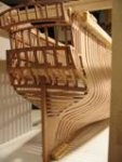
    Amendments of Cathead-rope
     
    Karl


  5. Like
    Jeronimo reacted to EdT in HMS Naiad 1797 by EdT - FINISHED - 1:60 - 38-gun frigate   
    Martin, I do not intend to paint anything. We do not know what the original decoration was so this is all speculative. We do know that at the time, the Admiralty was cracking down on decorative carving and trying (we don't know how successfully) to eliminate it.
     
    Yes Druxey, I agree on the open space. A few months ago I added some more water lilies. If I were doing these figures again, I believe I would also extend the arms of the figures just outside the ports up to the cap rail as in the original painting. I don't have the heart for that at this stage, although I may include a pattern for that pose in Vol2.
     
    Attached photo taken in February.
     
    Ed

  6. Like
    Jeronimo reacted to EdT in HMS Naiad 1797 by EdT - FINISHED - 1:60 - 38-gun frigate   
    1:60 HMS Naiad 1797
    Part 144–Stern Galleries 10 – Taffrail Figures Cont.
    Posted 7/23/12
     
    Work continues on the taffrail figures. The first picture shows the almost complete central figure temporarily pasted in place. The others were permanently installed last week.


    The next picture is a closer view of the central figure, a naiad in a pool of water surrounded by water lilies.


    There is no finish on these figures so the relief is still somewhat obscured by the sanding dust. These actually look better in real life – not always the case with the Naiad model photos. I may do something with the finish to accentuate the relief. Perhaps the wax will suffice but I may go to Tung oil. We’ll see. First some tests. Fortunately there are lots of first draft figures to practice on.
     
    The next picture shows the taffrail with the additional groupings of water lilies added.


    These are just pasted on. Some more fitting of all the last parts is needed to integrate them into the taffrail.
    The last picture shows a view from below the starboard quarter. The angled lighting helps with the relief in this photo.


    Ed
  7. Like
    Jeronimo reacted to EdT in HMS Naiad 1797 by EdT - FINISHED - 1:60 - 38-gun frigate   
    1:60 HMS Naiad 1797
    Part 143–Stern Galleries 9–
    Taffrail Figures Cont.
    Posted 7/16/12
     
    The work on the stern galleries continues. Progress seems slow. There has been a lot of rework. In the first picture the holes for the two chase ports are finally getting cut.


    After drilling holes as shown, the rough opening was cut using a jeweler’s saw and the holes were refined to the line on the pattern with files followed by a sanding dowel.
     
    The next picture shows the beading for one of the holes


    These were turned on the lathe from a piece of flat stock glued to a chucked piece with paper between the pieces. The inner diameter was turned first to match the opening and the outer diameter turned to give the width of the bead.
     
    At the same time work on the two figures over the stern windows was completed. The two are shown in the next picture picture as they near completion.


    These are a later version of the same pose shown in an earlier post - with more relief – but they are still friezes, not fully sculpted figure like the quarter posts. They were carved stepwise together to help keep the similar.
     
    The next picture shows the second figure being glued to the taffrail.


    Before this step and after removal from the carving block the carvings were sanded on the back surface to a thinner depth and the back of the figures carved to add some relief. Starting with a thicker carving blank allows for some error and some flexibility in the amount of relief of each part of the pose. This can be seen in the next picture..


    The back sides of the head, arm and leg in this view can be seen to be carved back where the meet the taffrail.
     
    The next picture shows the inverted model at its current stage.


    The aft windows of the quarter galleries have be reworked to incorporate a solid panel behind the simulated window grid. This seems to have been the most common practice for these windows.
     
    The last picture is another view of the stern at present.


    The central figure for the taffrail has not yet been added. There is also some additional “gingerbread” in the form of water lily carvings to be added, perhaps some additional bead rails and the name board.
     
    Ed
  8. Like
    Jeronimo reacted to EdT in HMS Naiad 1797 by EdT - FINISHED - 1:60 - 38-gun frigate   
    1:60 HMS Naiad 1797
    Part 142–Stern Galleries 8–Quarter Gallery Windows
    Posted 7/16/12
     
    There were some comments on milling the windows. Milling these small pieces, for me at least, was the easiest part of the job – compared to assembling these and fitting them into the window openings. These later steps require a steady hand and that is a problem. The first picture shows the milling setup used to notch the pieces
    .


    The slotting saw blade is about 2” thick (.028”). The only one I had of this size was 4” in diameter, hence the oversize blade in the picture. Two-inch thick stock is held down in the jig with two screws with large round heads. The angle is set to the angle of the windows, in this case the quarter gallery windows. A small strip helps keep the wood tight to the jig, but many of the cuts required holding down the piece. Once set up the cutting of the slots was easy using the calibrated wheels to match the 9” x 10” size of the panes.
     
    The next step is a bit more fun. The next picture shows a window being assembled.


    In the next picture an inside grille is being fit into its frame.


    This was done by sanding the frames until they just fit. The inside grilles were installed deep enough in the frame to allow a second grille to be fit over the glass – a piece of transparency film.
     
    In the next picture the forward window with its glass and outer grille has been installed.


    The outer grille of the second window is fit into place and slight differences between the inner and outer matching grilles are being filed out. Also, a slight bevel was put on the outer mullions at this stage. The outer grille was then removed, the glass fitted and the grille glued back in over it.
     
    The last picture shows the finished quarter gallery windows.


    Ed
  9. Like
    Jeronimo reacted to EdT in HMS Naiad 1797 by EdT - FINISHED - 1:60 - 38-gun frigate   
    1:60 HMS Naiad 1797
    Part 141–Stern Galleries 7–Quarter pieces/Stern lights
    Posted 7/11/12
     
    With all the excitement over the shingles, which were corrected in the last post, I was evidently distracted enough to install the quarter piece figures incorrectly. I posted the incorrect installation in the last post before realizing that I had installed them on the quarter pieces instead of making them appear as an integral part of the quarter pieces - as I had intended. Senility may be approaching. So, the first picture shows the corrected installation on the starboaed side.


    In this picture the quarter piece has been beveled off and the figure installed as if it were part of the piece. This was the original plan. The next picture shows another view.


    In addition to being more correct, the figures look better. They appear to be more upright (as designed) and not falling forward so much due to the angle of the stern.
     
    After some redesign and some process development (with some suggestions and help from Keith), I returned to the work on the stern lights. The next picture shows work on the window grilles assembly.


    The lapped joints were cut with a .028” slotting saw blade on the milling machine, using the calibration wheels to size the 10” X 9” panes, so the mullions are about 2” square. The horizontal mullions are being fixed to the frames first in this picture because the tight fit helps hold the assembly together better initially than the lapped corners would do. The angles of the central five windows could be achieved by angling the frames while the glue was soft. The outer windows and the quarter gallery windows will have their parts milled at an angle.
     
    The central window installation is shown in the next picture.


    The outer grilles were installed first. The frames were sanded to get a tight fit. A thin sheet of plastic was then inserted on the inside and the inside grille fastened over it, so the plastic itself is not glued. (The glass is still hard to keep clean.) The quarter gallery windows will have to be completely installed from the outside – inside grilles first. This picture also shows a pattern fragment pasted to the taffrail to facilitate cutting the chase ports.
     
    The next picture shows the windows from a different angle and also the figure on the port quarter piece.


    The last picture shows the windows from the inside.


    Ed
  10. Like
    Jeronimo reacted to EdT in HMS Naiad 1797 by EdT - FINISHED - 1:60 - 38-gun frigate   
    1:60 HMS Naiad 1797
    Part 140–Stern Galleries 6–Quarter Galleries/Trim
    Posted 6/26/12
     
     
    Comments on the last part convinced me that my shingled roof over the quarter gallery needed to be reworked. I still do not know how these were constructed on the original ships – they may have been lead sheet – but the way they were handled on contemporary models is clear. I decided to mimic that, but still using individual shingles. The new shingles are paper thin and wider. The next picture shows these. There is still a bit of work to do on the front tiles.


    The decked area above the shingled finishing piece is only pinned at this stage, pending the final cleanup of the shingles. This picture also shows the cap molding fitted to the top of the taffrail and also the permanent attachment of one of the Naiads.
     
    The next picture shows another view of the shingles – and the starboard quarter piece Naiad.


    And one more for good measure.


    This picture also shows the central stern window installed and more of the taffrail cap molding.
     
    The next picture shows another view of the window, the entire cap molding, and both quarter piece Naiad figures.


    With the figures glued on, the fingers of their raised hands can be carved. Although I tried to give the arms some strength by running the wood grain from the outside foot to the hand, I didn’t want to risk an arm fracture so the detailing of the hands was deferred until the they were fixed in place on the rail.
     
    This first window, although glued in, is a test. The window parts were milled so the grid parts interlock and also fit into mortises in the sides, tops and bottom frame pieces. The grid mullions are 1 ¾” square (.028”), so all the notches were dadoed with a .028” thick circular blade on the mill with the pane size and the notch depth set with the mill’s calibrating wheels. The frame was made slightly oversize and custom fit into the windw opening.
     
    The window has a thin piece of clear plastic sandwiched between two grids. This can be seen in the next picture.


    The grids have to be matched. They are also beveled after assembly on the side away from the glass to avoid a squared appearance. The sandwich construction allows them to appear correct when viewed from both sides – but it doubles the work.
     
    I can only deal with the fitting of these tiny window parts in small doses, so I am splitting time between that and some of the other work to keep my sanity.
     
     
    Ed
  11. Like
    Jeronimo reacted to EdT in HMS Naiad 1797 by EdT - FINISHED - 1:60 - 38-gun frigate   
    1:60 HMS Naiad 1797
    Part 139–Stern Galleries 5 –Quarter Galleries/Trim
    Posted 6/24/12
     
    The quarter galleries and some trim needed to be installed before moving on to the windows. Before doing that I set the model up on the shipway for some dimensional checks. This is always a good idea, but in this case it was a very good idea, because I found that the upper stools on the quarter galleries were set over a foot too low. So the stools and the construction on top of them had to be removed and scrapped. This also explained why the pieces cut from the patterns did not quite fit in the original installation. I spent some time with the drawings , unsuccessfully trying to solve this mystery.
     
    In the first picture the new stools have been installed at the correct height. This was done on both sides


    This picture also shows the two lower rails and the planking between them installed on the starboard side. The port side will be left unplanked with only the main structural members modeled.
     
    In the next picture the window mullions and lower sills have been installed and the upper rail and capping of the lower sills is being glued and clamped in place.


    The clamping of all these parts was quite awkward. The alignment and spacing of the three window mullions has to be precise or the windows will look odd. This could not be done accurately using the mortises for these previously cut into the lower sill, so after aligning and end gluing the mullions to the stools, they were bolted through the top stool and secured at the bottom by the sills between them and the outer capping being installed here..
     
    The next picture shows this construction after removal of the clamps and pins.


    At this stage the upper finishing was fit and installed on top of the upper stool. The next picture shows this in place and the roof shingles over it being installed.


    These were sliced off of a shaped, cross-grain strip with a razor blade. There are three rows as shown in the next picture.


    In this picture the top and an integral outside molding is being fitted. There will be some fretwork placed on top of this but that will be done much later after completion of the side planking.
     
    Trim cove pieces to fit over the quarter gallery windows below the taffrail were made by machining a circular section of molding as shown in the next picture.


    This could have been turned on the lathe, but the milling machine was used instead with a rotary table. This allowed the same round cutter to be used that was used to make the larger central section of this molding. The next picture shows these two end pieces added to the taffrail.


    The diameter of these end moldings was determined from the drawing showing the true view of the taffrail. This view was used to make the patterns for cutting out the outer taffrail, so the curved pieces fit almost perfectly – a slight bit of clamping pressure helped on one of them.
     
    Ed
  12. Like
    Jeronimo reacted to Michiel in Prins Willem 1650 by Michiel - 1:50 - POB Zeeland ship from own plans   
    The underwaterschip is now painted:


    I see now on the picture that some corrections are still in order :mellow:
     
    the bow:


    and the first work on the second gundeck:


    Have fun,
    Michiel
  13. Like
    Jeronimo reacted to Michiel in Prins Willem 1650 by Michiel - 1:50 - POB Zeeland ship from own plans   
    What was done before part 3:
     
    some more details shots:
     

    batteries and switch for the lighting
     

    inner planking
     

    First carving
     

    Cabin
     

    More carving
     

    just before painting...


    Have fun,
    Michiel
  14. Like
    Jeronimo reacted to Michiel in Prins Willem 1650 by Michiel - 1:50 - POB Zeeland ship from own plans   
    another part finished for the lower deck.


    This time fully scratch in every sense: the wood is pear from the garden, saved from the firewood pile..
  15. Like
    Jeronimo reacted to Michiel in Prins Willem 1650 by Michiel - 1:50 - POB Zeeland ship from own plans   
    Some more progress on the planking of the gundeck...


    Wooden nails in the planks and iron bolds in the schaarstokken.
     
    Best,
    Michiel
  16. Like
    Jeronimo reacted to Michiel in Prins Willem 1650 by Michiel - 1:50 - POB Zeeland ship from own plans   
    In the meanwhile I also finished the rack of muskets, so that asks for new photo's of the cabin:


    Best,
    Michiel
  17. Like
    Jeronimo reacted to Michiel in Prins Willem 1650 by Michiel - 1:50 - POB Zeeland ship from own plans   
    Thanks Sherry,
     
    Here's some more:
     
    in total there will be 5 ankers of different sizes and, related different rope strengths. Three on port and 2 on starboard.


    And as can be seen here already I started making the iron bolds:


    Any guess what they are made from?
     
    cheers,
    Michiel
  18. Like
    Jeronimo got a reaction from Luca in LE BONHOMME RICHARD by Jeronimo - FINISHED   
    Amendments of Cathead-rope
     
    Karl


  19. Like
    Jeronimo got a reaction from Stockholm tar in LE BONHOMME RICHARD by Jeronimo - FINISHED   
    Amendments of Cathead-rope
     
    Karl


  20. Like
    Jeronimo got a reaction from gieb8688 in LE BONHOMME RICHARD by Jeronimo - FINISHED   
    Amendments of Cathead-rope
     
    Karl


  21. Like
    Jeronimo got a reaction from archjofo in LE BONHOMME RICHARD by Jeronimo - FINISHED   
    Amendments of Cathead-rope
     
    Karl


  22. Like
    Jeronimo got a reaction from janos in LE BONHOMME RICHARD by Jeronimo - FINISHED   
    Amendments of Cathead-rope
     
    Karl


  23. Like
    Jeronimo got a reaction from Michiel in LE BONHOMME RICHARD by Jeronimo - FINISHED   
    Amendments of Cathead-rope
     
    Karl


  24. Like
    Jeronimo got a reaction from Wishmaster in LE BONHOMME RICHARD by Jeronimo - FINISHED   
    Hello,
     
    Foremast, Foretop, Bibbs, Rubbing-paunch
     
    Karl


    T e i l  23


  25. Like
    Jeronimo got a reaction from dafi in LE BONHOMME RICHARD by Jeronimo - FINISHED   
    Hello friends,
    I have a mistake of the rope from the Cathead to the three block-in.
    Change takes place coming soon.
     
    Vielen Dank an Günter Ulrich für den Tip.
     
    Regards Karl

×
×
  • Create New...