HOLIDAY DONATION DRIVE - SUPPORT MSW - DO YOUR PART TO KEEP THIS GREAT FORUM GOING! (83 donations so far out of 49,000 members - C'mon guys!)
×


Glenn-UK
-
Posts
3,162 -
Joined
-
Last visited
Content Type
Profiles
Forums
Gallery
Events
Everything posted by Glenn-UK
-
 Looks great and very neat work 👏
 -
Possibly, but I have no experience with shellac. My thoughts are you just need something which is clear when dry and will provide some level of adhesion when as it dries.
-
It works well, pe parts can be adjusted when first positioned and no nasty ca overspill issues
-
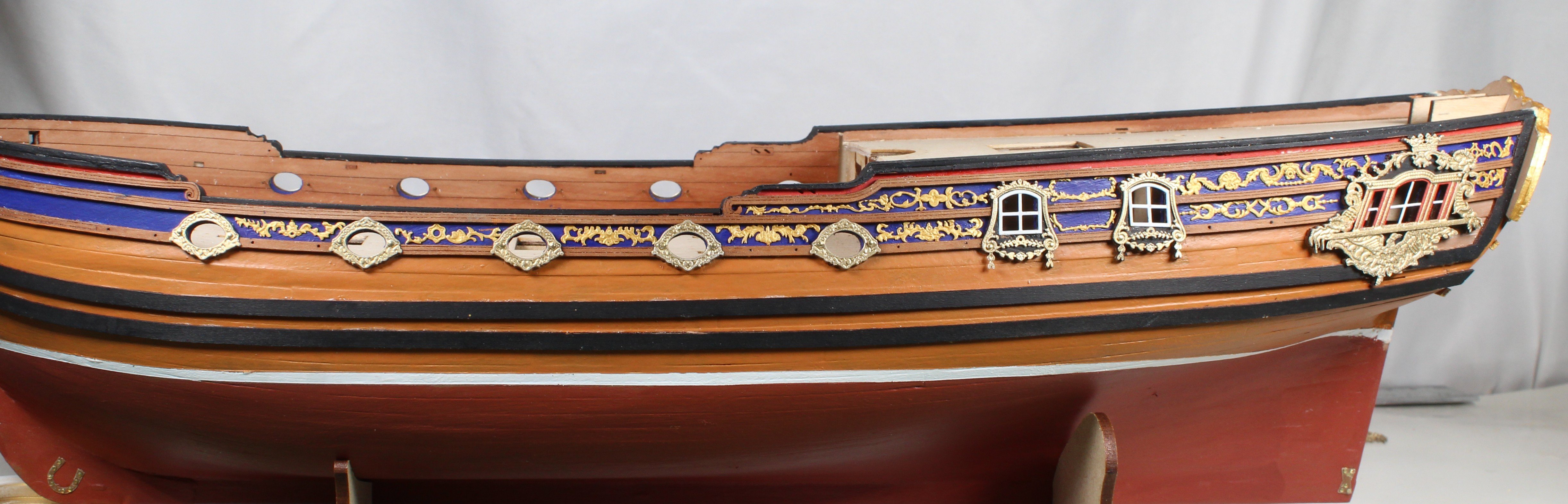
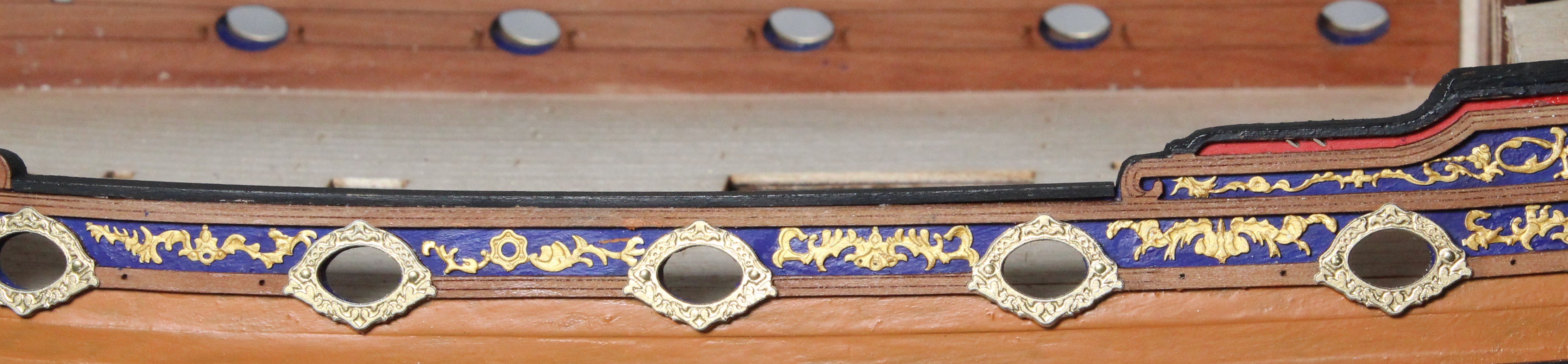
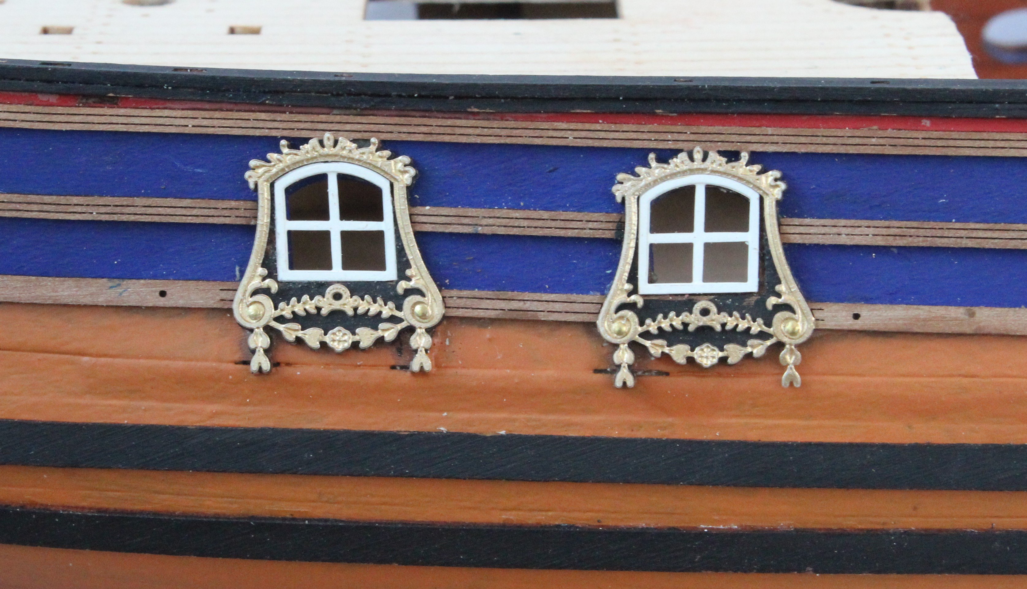
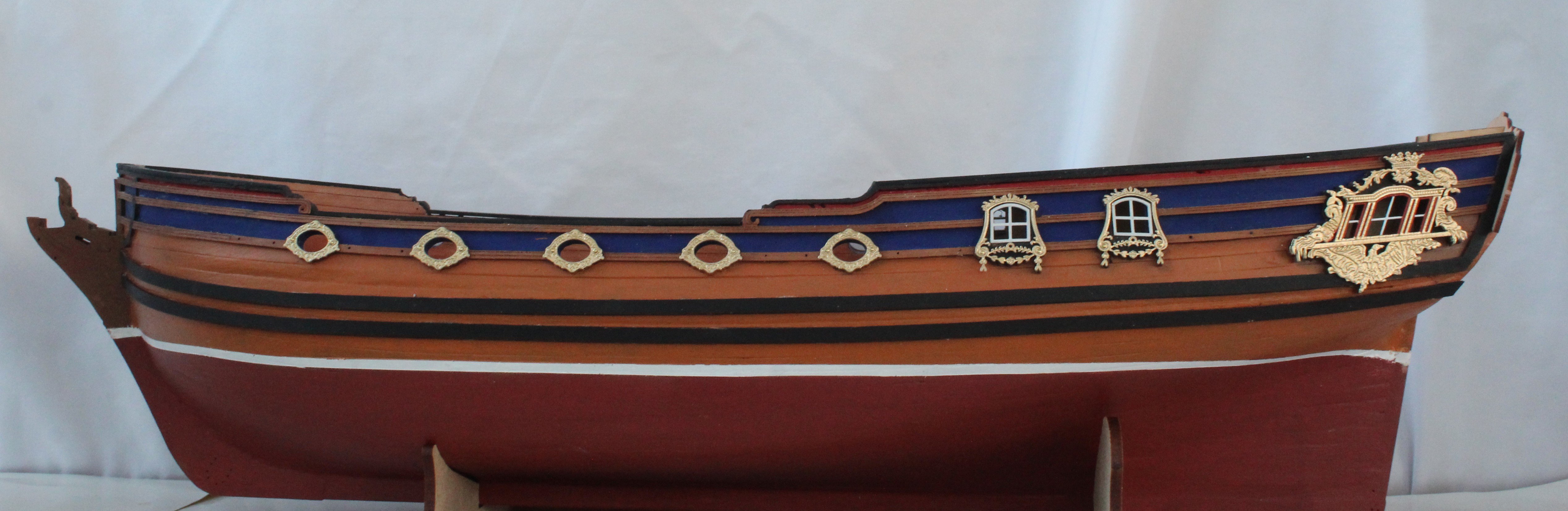
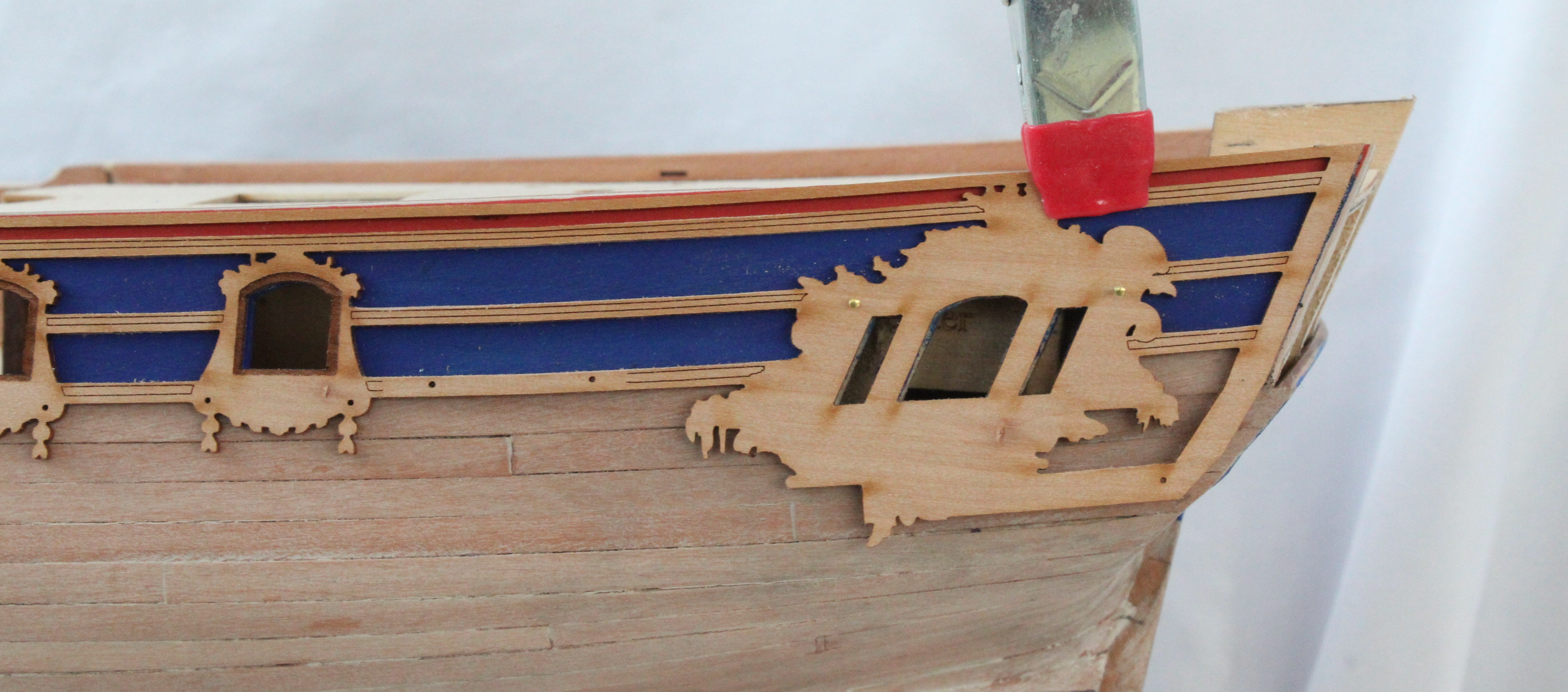
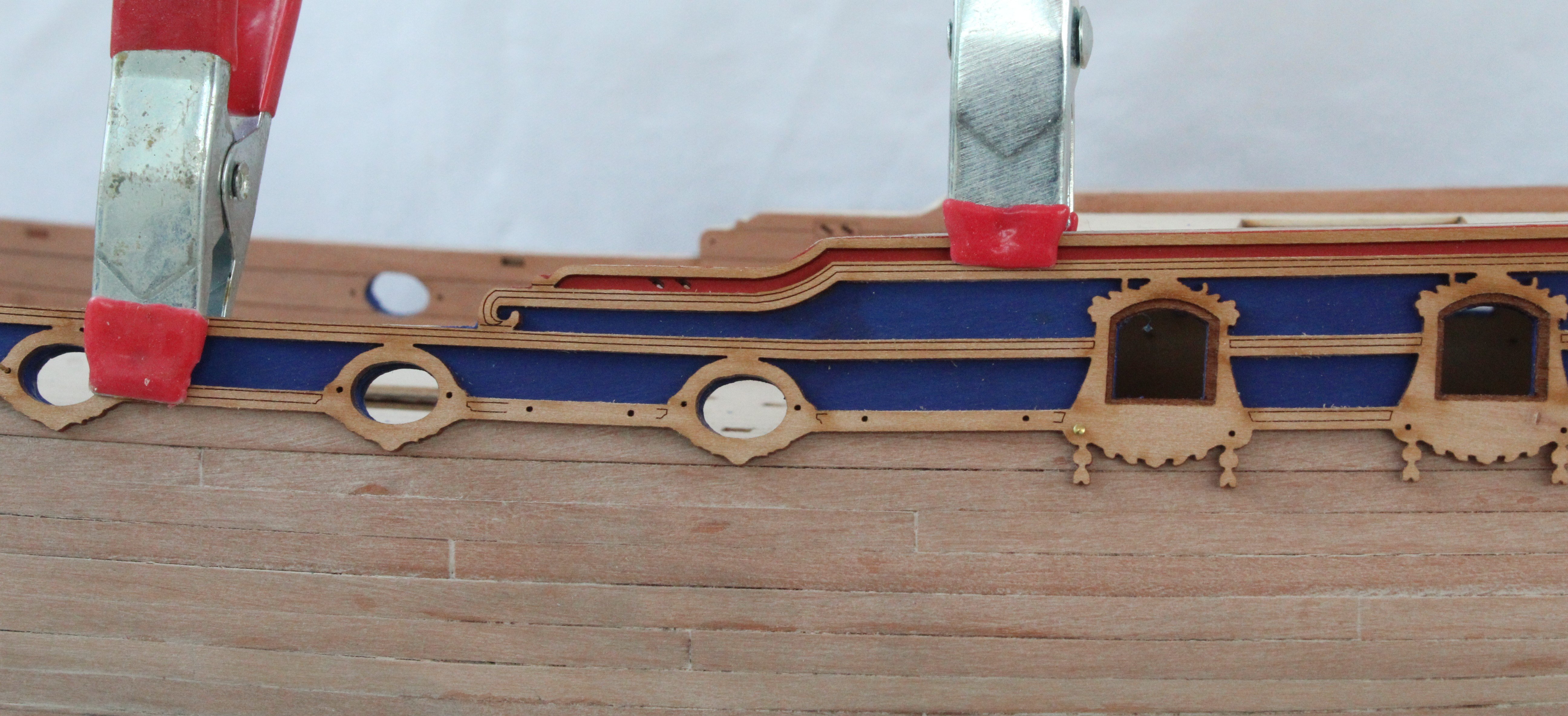
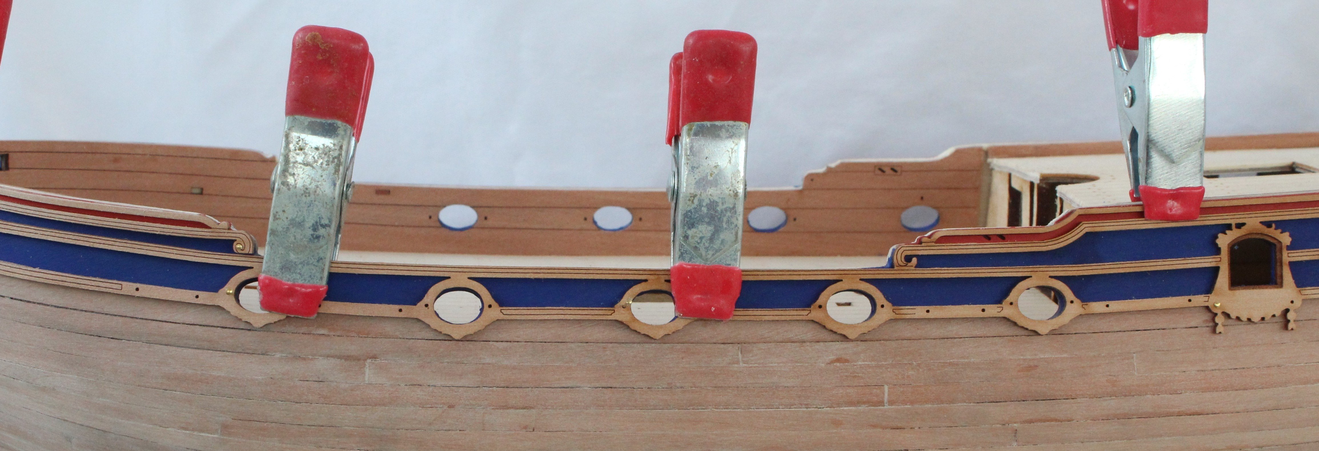
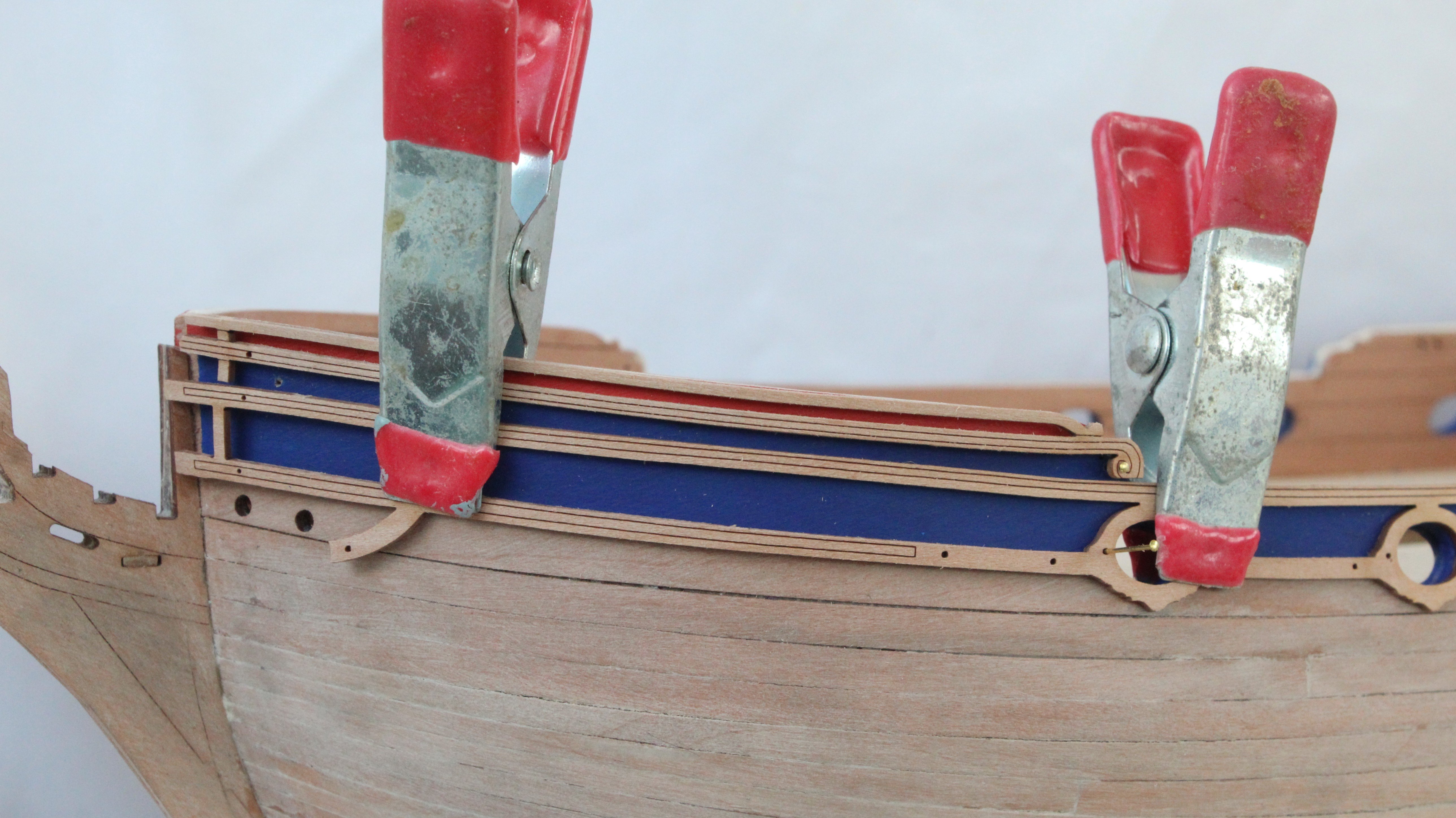
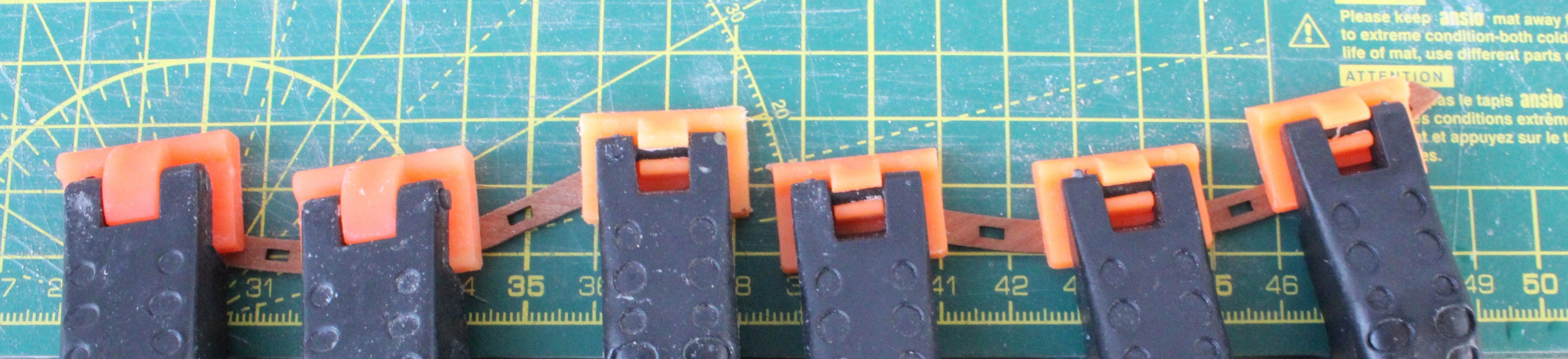
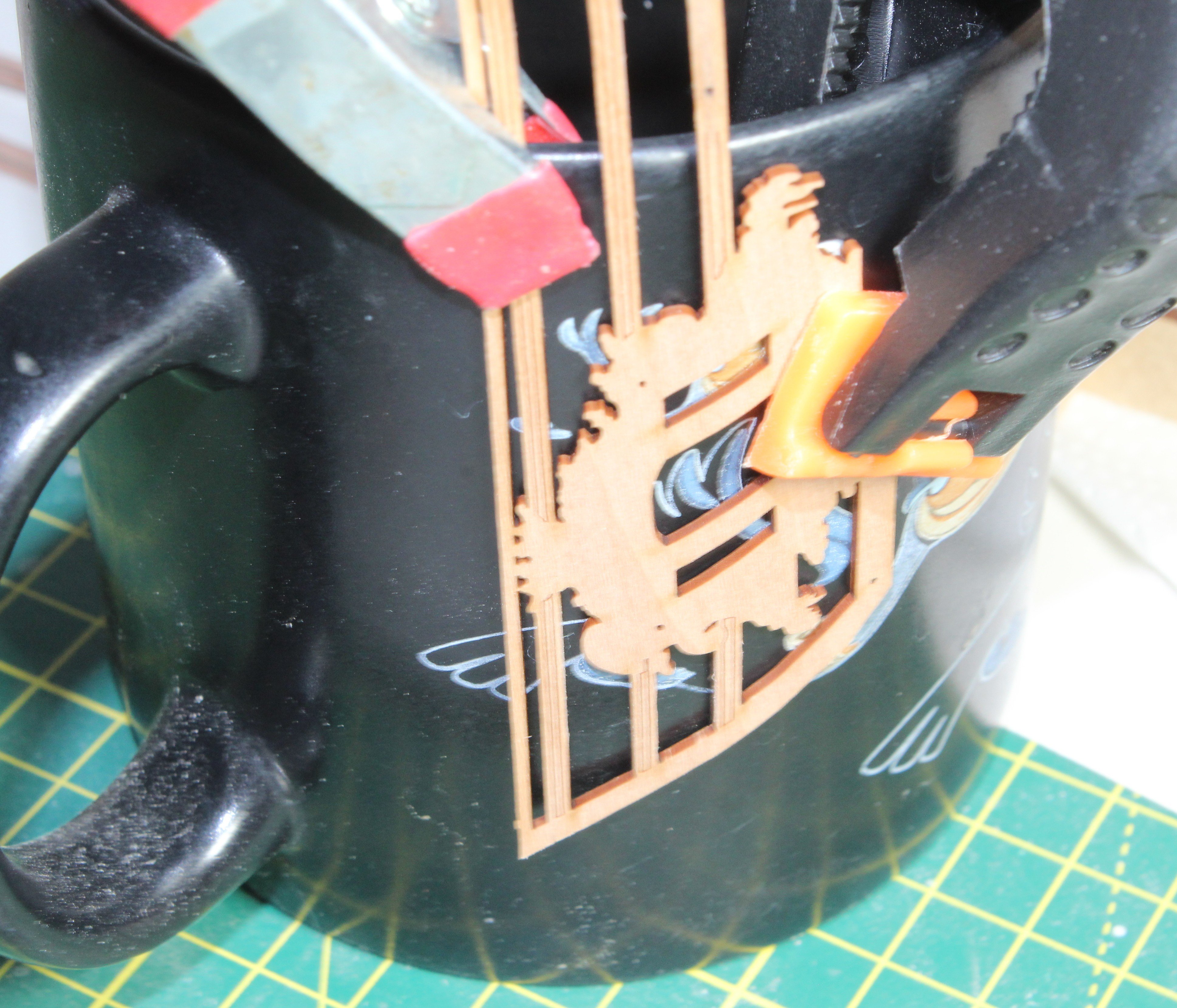
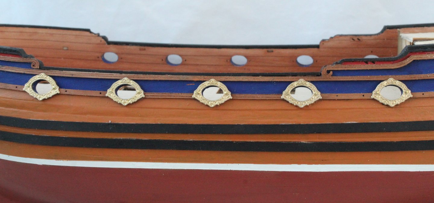
Build Log – Post 32 (29th Dec 2025) Task 53 – Hull Decorations I have now started to add the PE decorative patterns to the hull. I am coating each section of the hull with a thin coat of polyurethane varnish. I then wait for a few minutes to allow the varnish to get tacky before placing the PE pattern in place. Once the pattern has been positioned and being held in place by the varnish, I then apply a top coat of varnish. So far, this method seems to be working really well. Photos


-
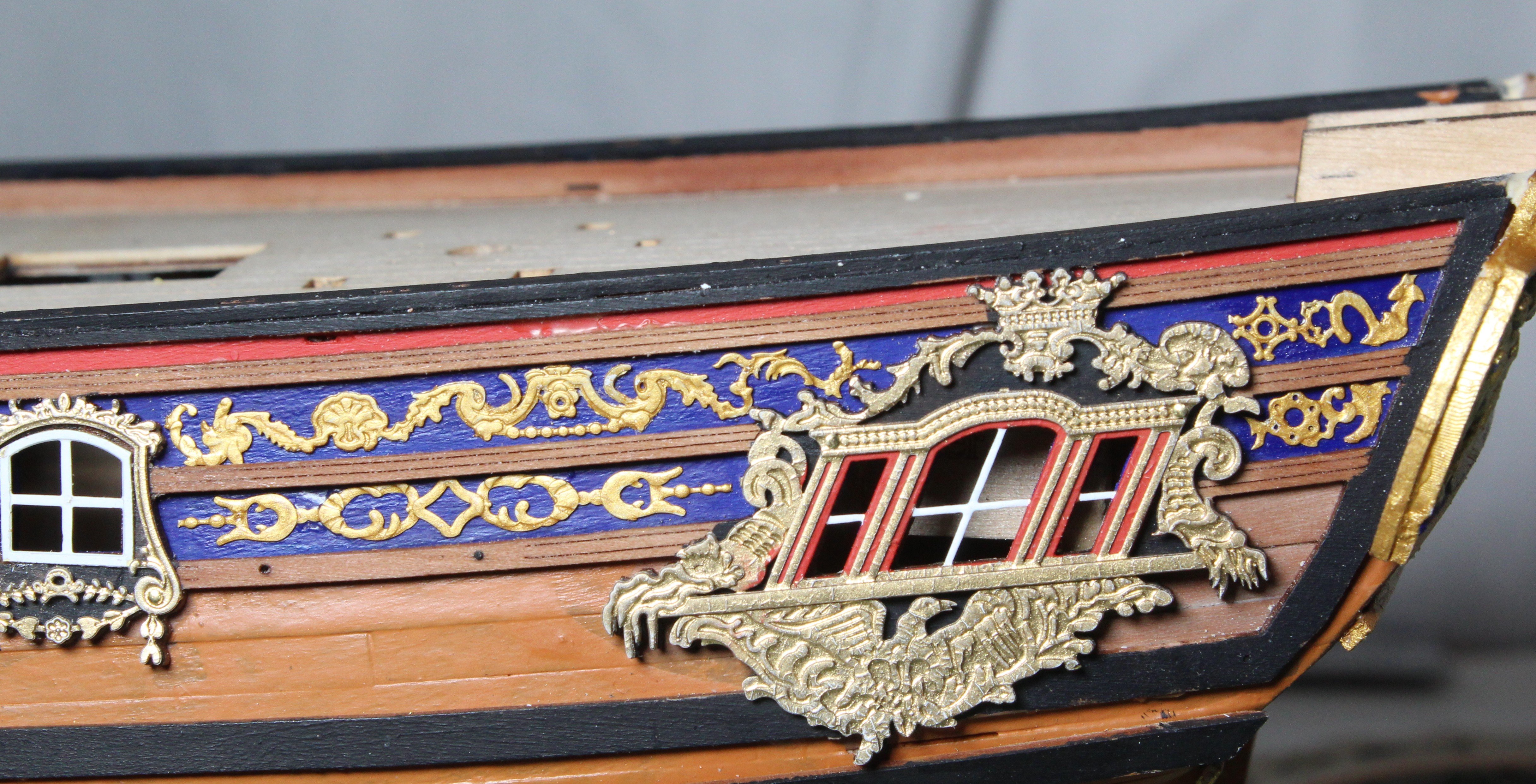
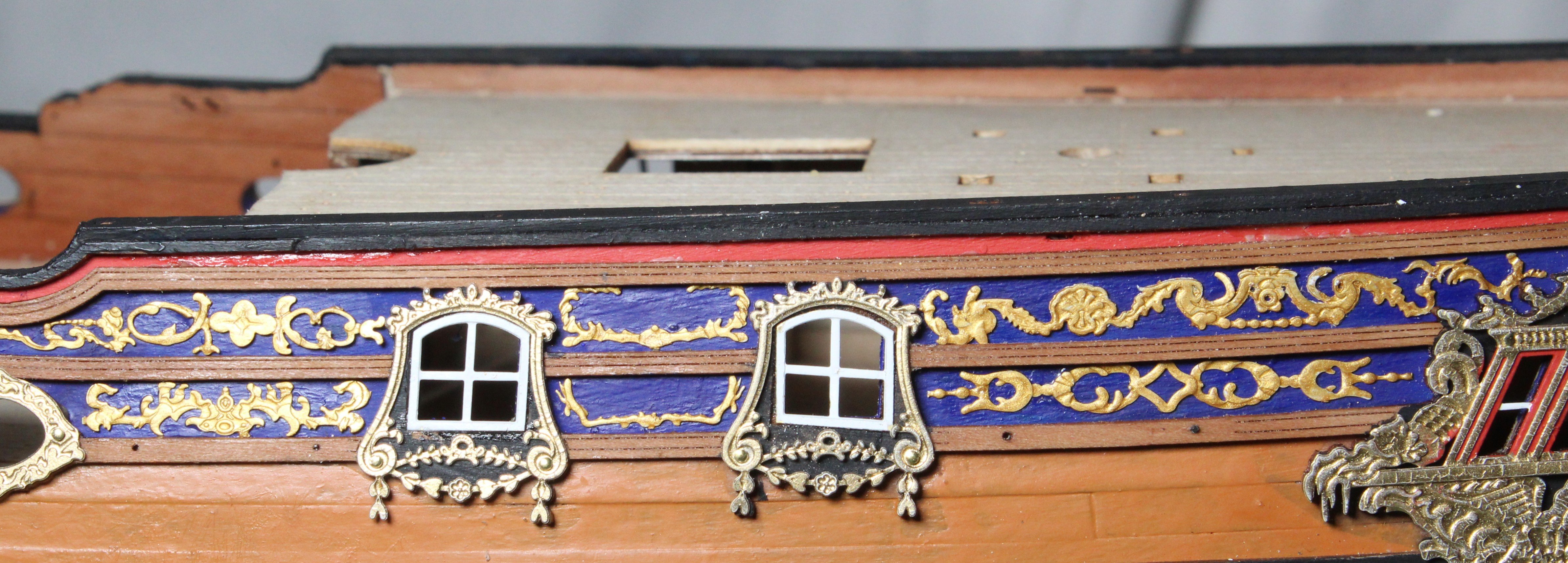
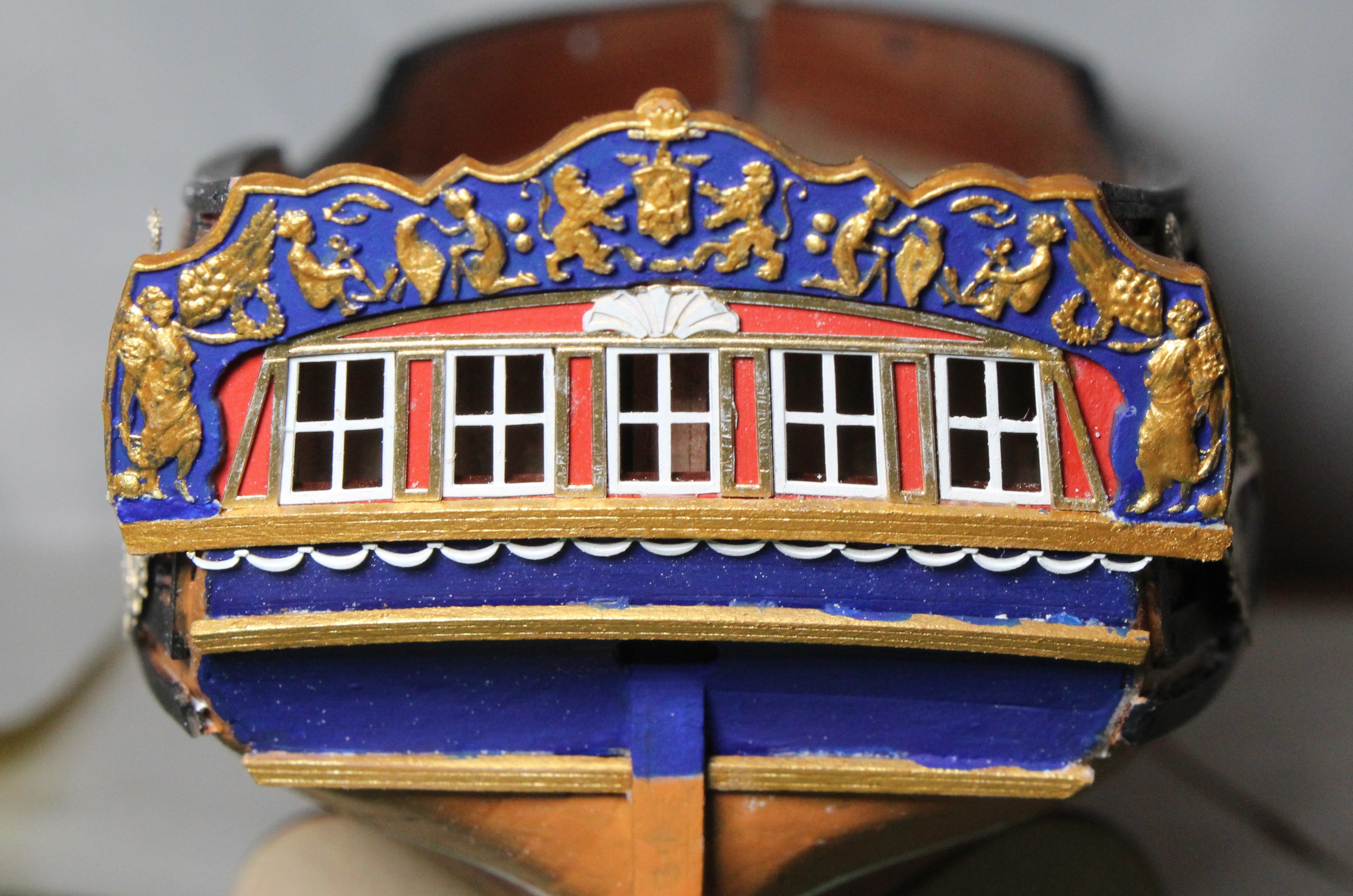
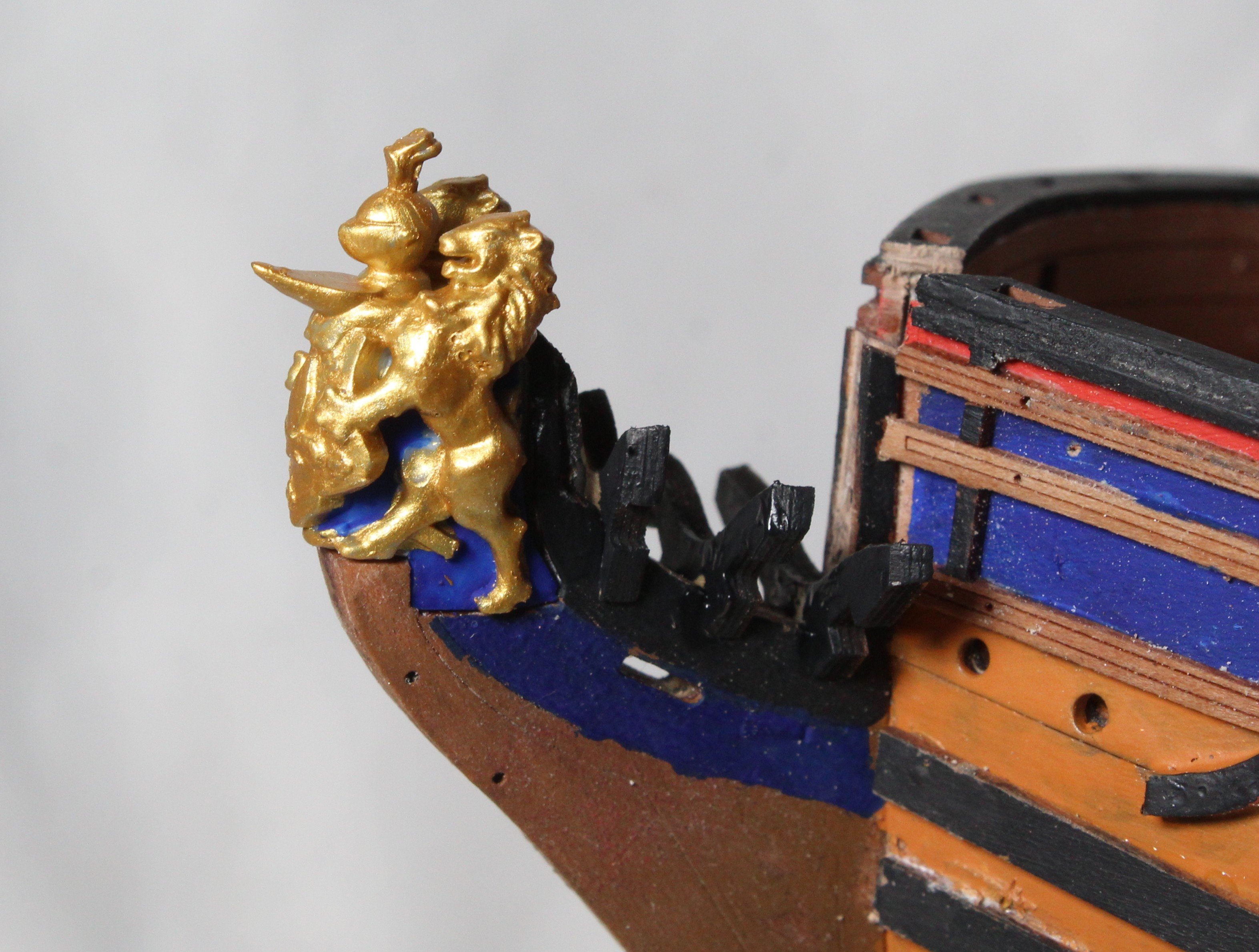
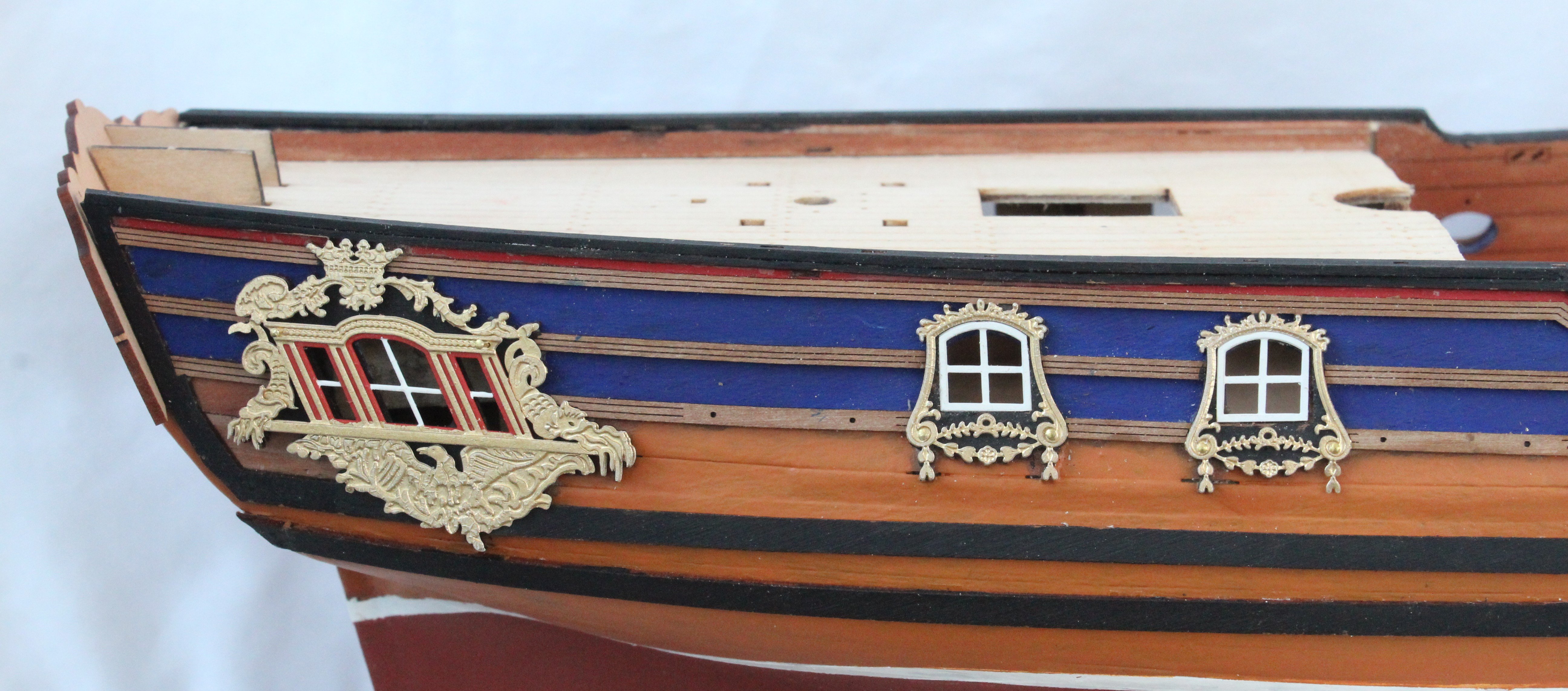
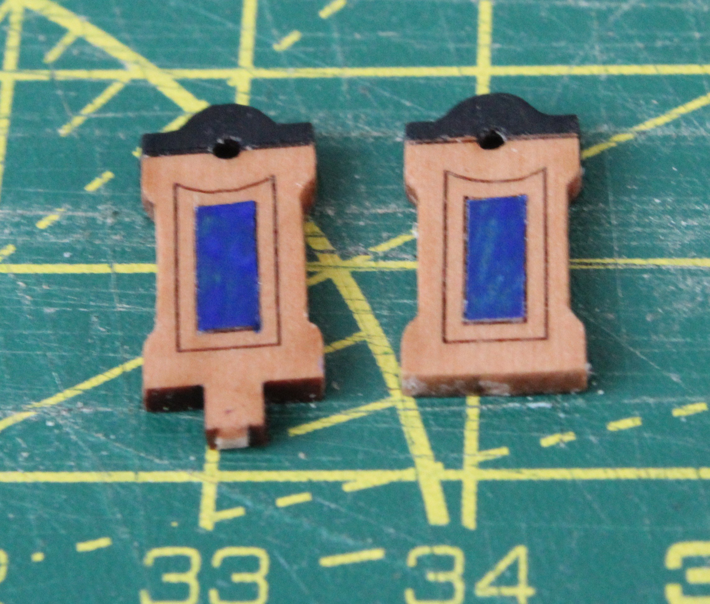
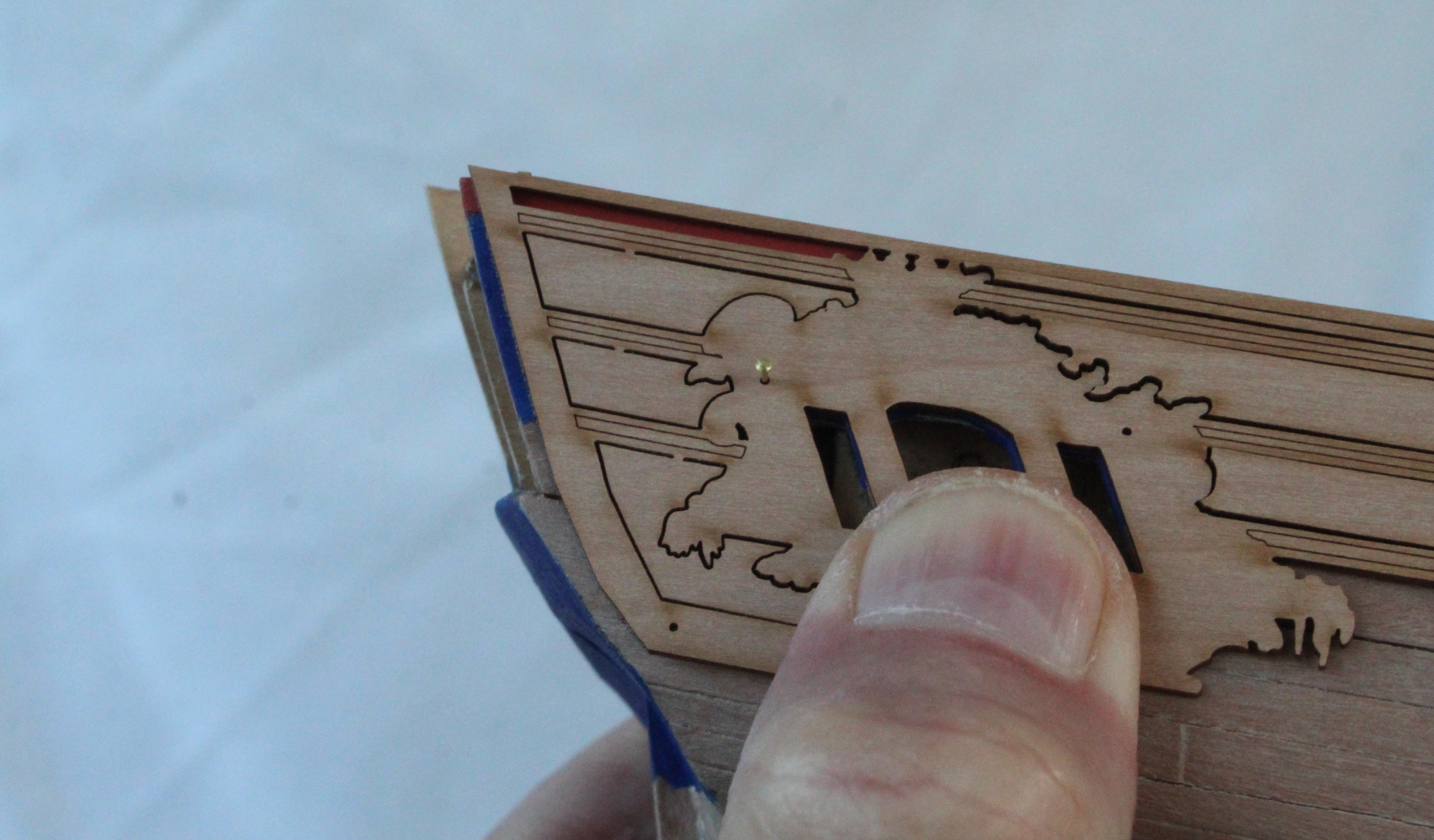
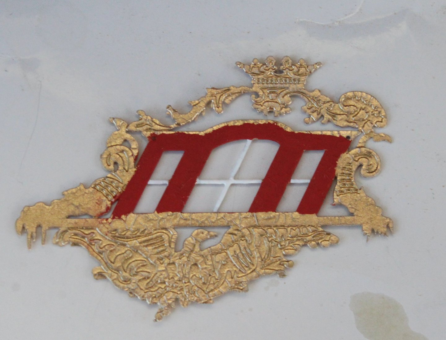
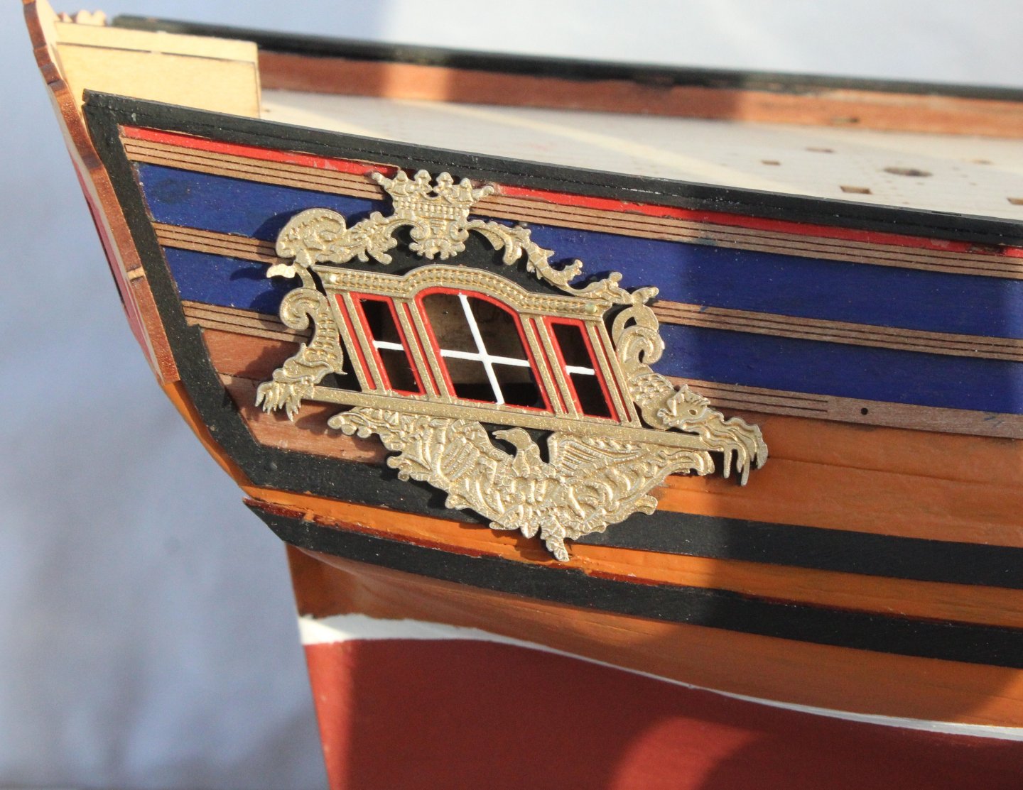
Build Log – Post 31 (24th Dec 2025) Task 51 – Upper Stern Counter Over the last few days I have been adding the various items to the upper stern counter. The first task was to add the white painted window frames. Next the window surround PE part was added. This had been painted gold with a white crest. The next item to fit was the 3D printed surround. The part was soaked in hot water for 15 seconds and then clamped to the stern counter for 1 minute so the bend could be added. The bent part was then dropped in cold water to cool off. The part was then painted imperial blue. Once the paint had dried the various raised shaped were painted gold. Once I was happy with the painted part it was added to the upper stern counter. Next I added the various rails, which had been painted gold. Finally, the final PE pattern, which had been painted white was glued beneath the upper rail. As can be seen in the photo below a little bit of paint touch up work is still required. Task 52 – Figurehead The figurehead has now been painted and test fitted.


-
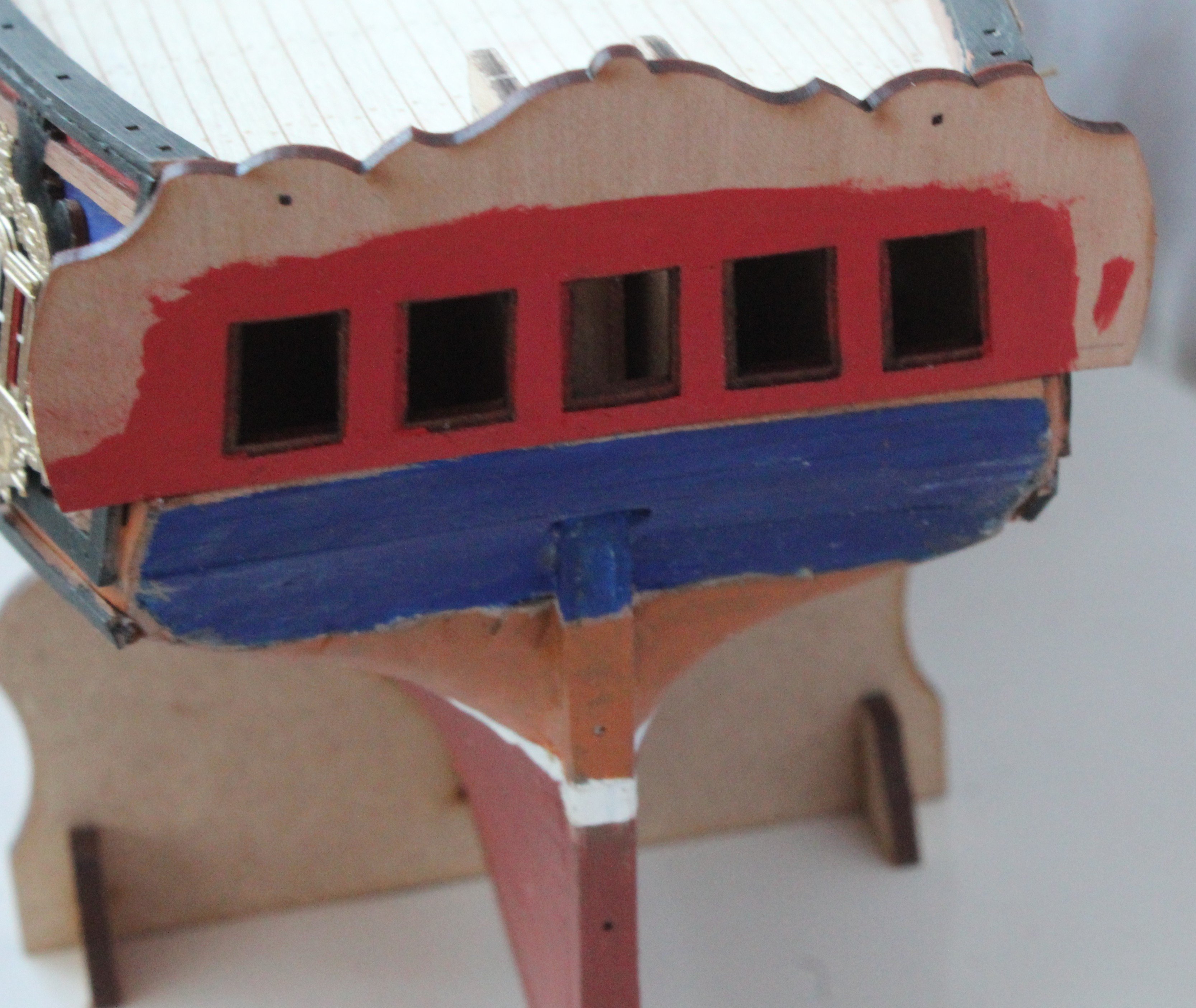
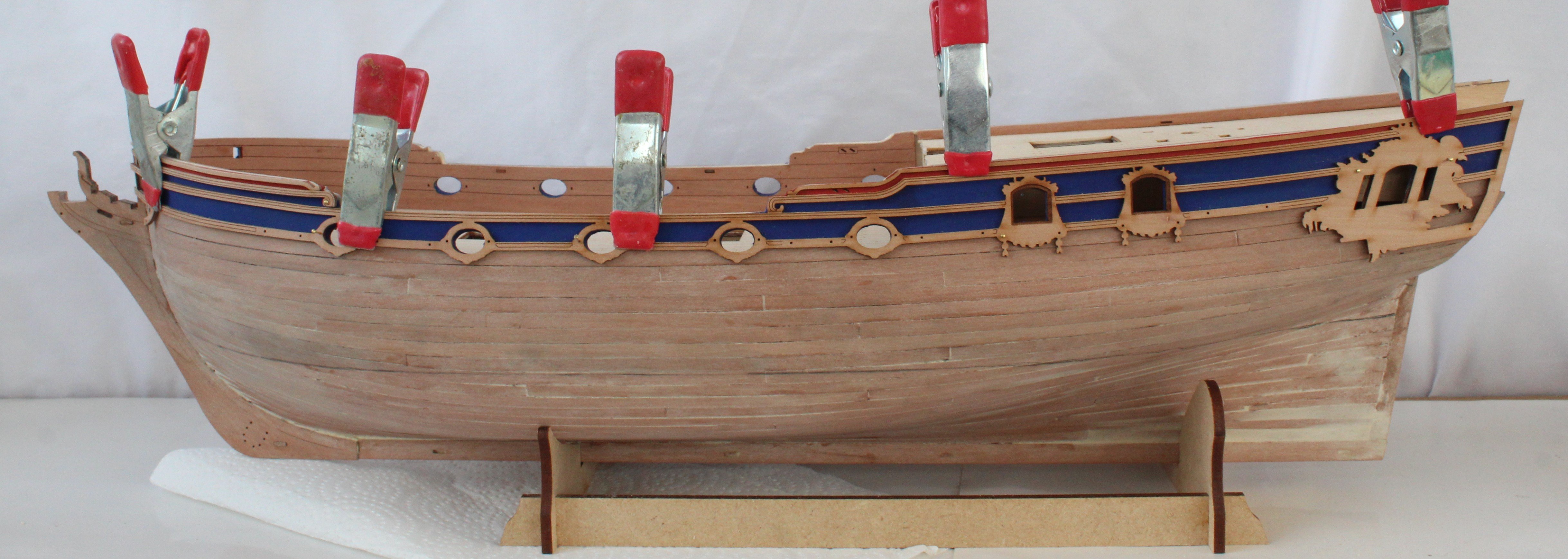
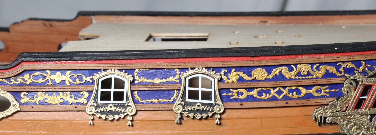
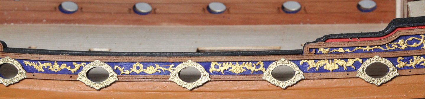
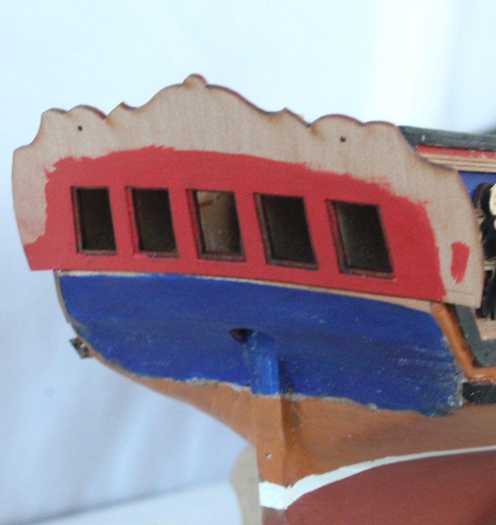
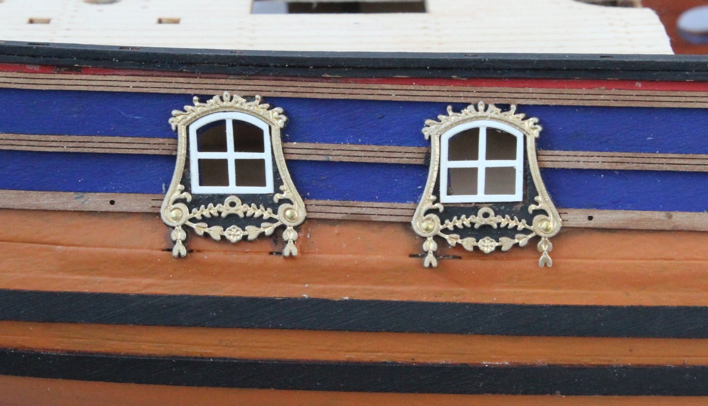
Build Log – Post 30 (19th Dec 2025) Task 50 – Upper Stern Counter Once the wales had been glued place I moved on to adding the upper stern counter pattern which was a relatively straightforward task. I did apply the red paint before this part was glued to place. Task 51 – Test Fitting Hull PE Patterns The main cabin decorative window comprises two PE parts. I had previously sprayed these parts with gold paint. The lower PE part window frame area then needed a red outline and window frames painted white. Using the pin holes to correctly align these two parts (not glued for the time being) a test fit was undertaken. I was happy with how this looks. I then glued the 4 off window frame PE parts to the side windows and test fitted the window surround patterns. Again, everything looks good. I will need to fill the gaps in the planking Next I decided to test fit the gun port surrounds. With these decorative patterns temporarily in place the build is starting to look like a royal ship fit for a duchess.


-
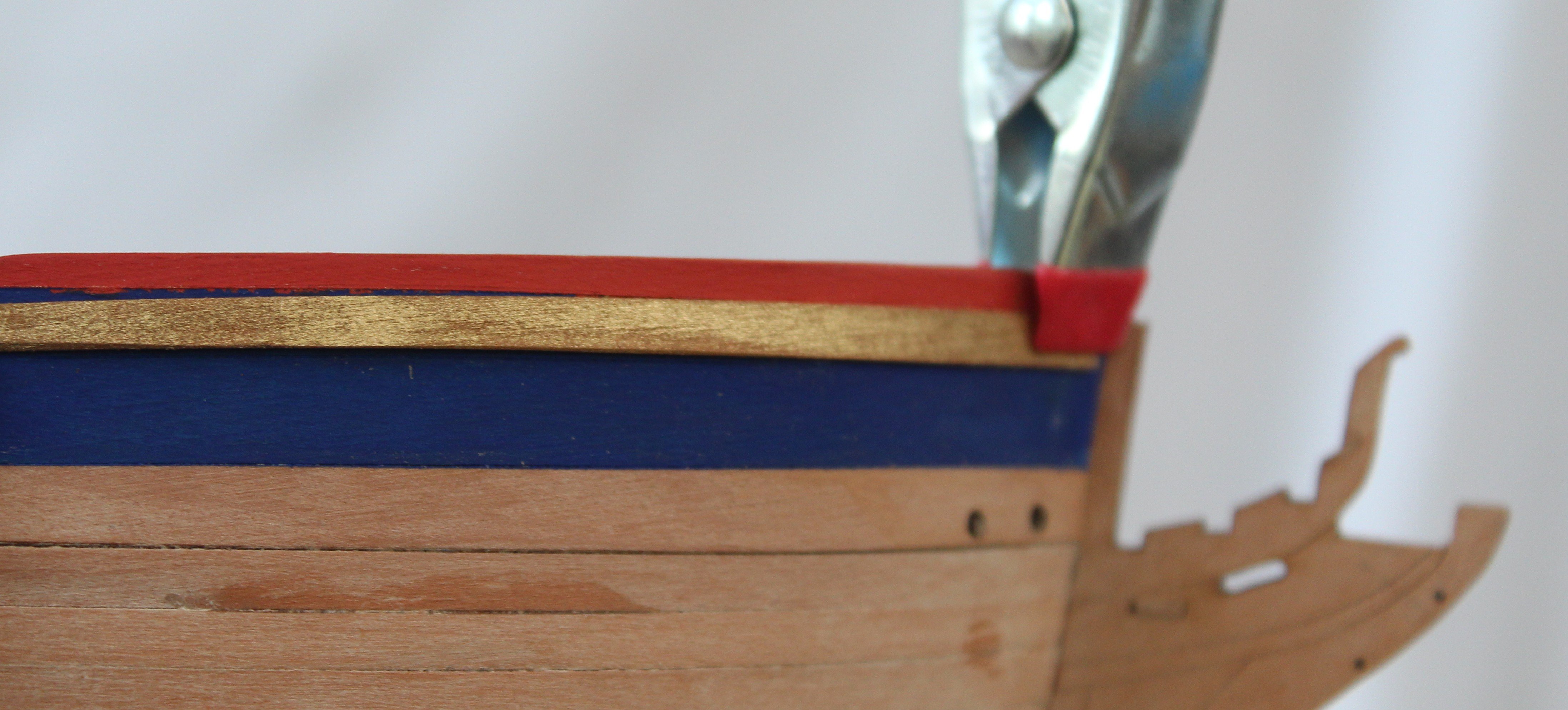
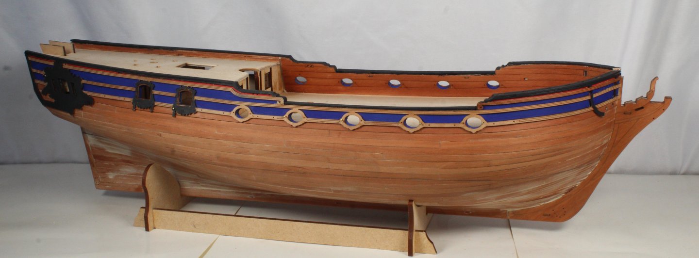
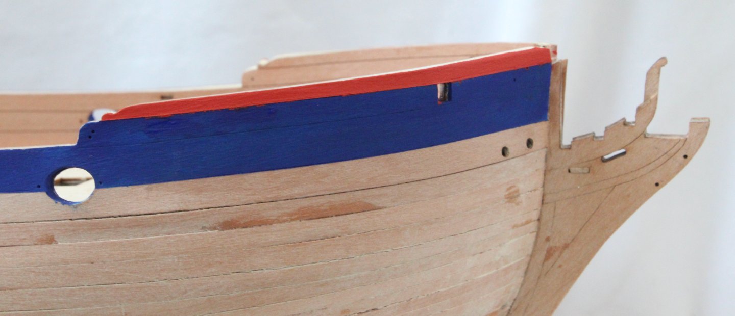
Build Log – Post 29 (17th - 18th Dec 2025) Task 49 – Painting the Hull I went off the reservation with this task *** the build instructions are to leave it a plain wood finish above the water line and a painted white hull below the waterline. This is exactly what I did with my previous DOK build and it does look great. However, on this build I decided to experiment with a different paint finish. I really like the Plasti-kote Red Oxide finish I have used on some previous build. I also liked having a thin white band for the waterline. With the waterline drawn I added some masking tape above and below the waterline and added a white band. After a couple of coats of white paint, the tape was removed. A new thin strip of tape was then placed oved the painted waterline. I then added three coats of red oxide paint below the water line. I opted to decant the paint from the spray can and apply with a paint brush. I also added a different paint finish above the water line (leather). The finished paint scheme is shown below. Whilst it may not be in keeping with how ships of this period looked I quite the colour scheme, noting it may not be to everyone’s taste. This paint scheme is probably more common for fishing boats. Next task will be to add the wales.

-
Build Log – Post 28 (16th Dec 2025) Task 48 – Main Rails and Gunwales Adding the main rails has been a bit of nightmare as I made a schoolboy error by applying a coat of tung oil to the hull. This meant that when I was ready to add the main rails it was difficult to get the to hold, once dried. The rails are now in place and hopefully they will now stay in place. Next the gunwales were added. They were painted black before they were fitted. Once fitted I decided to paint the upper bow and stern rail black. Photos Current status of the build Bow area main rails Midships main rail Stern area Gunwales


-
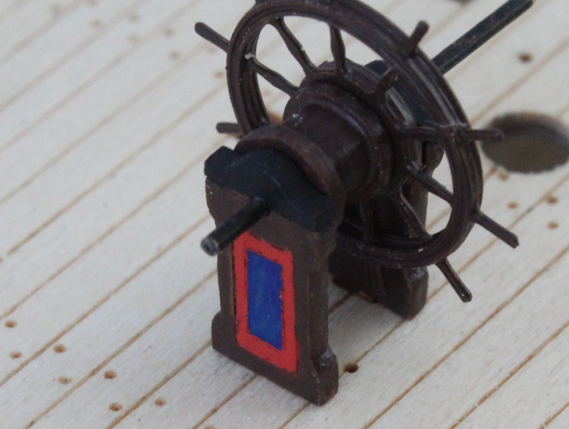
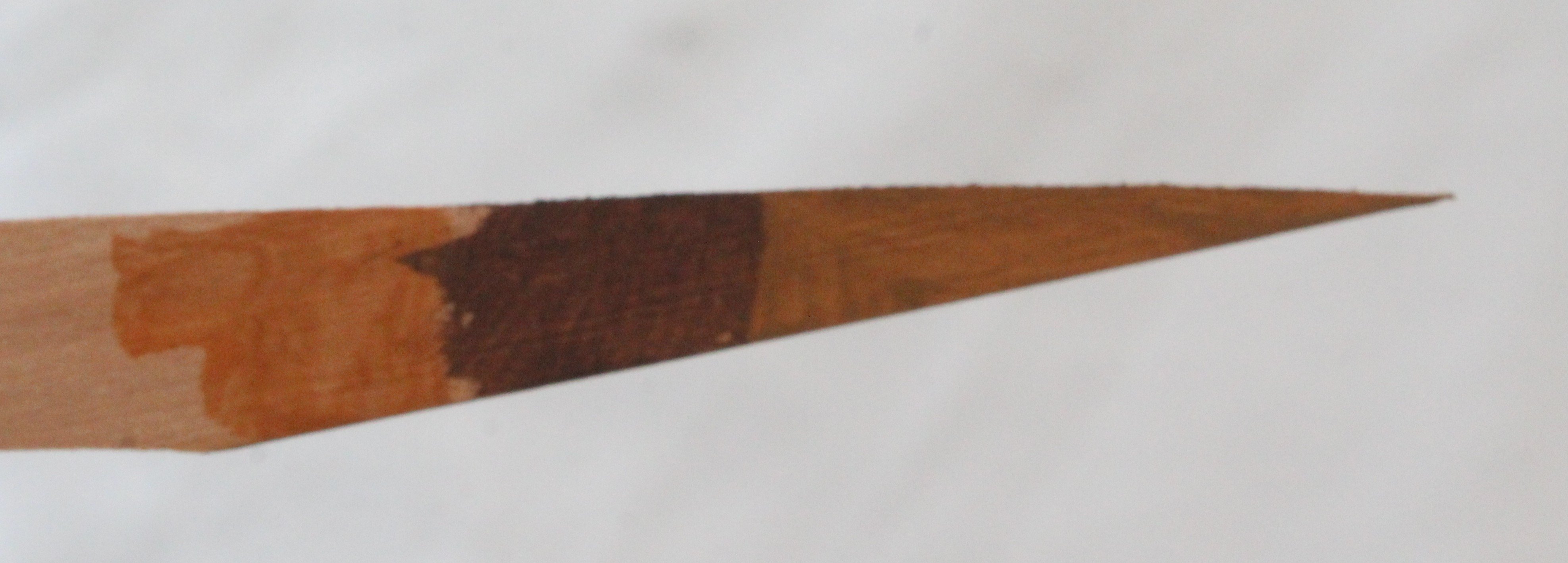
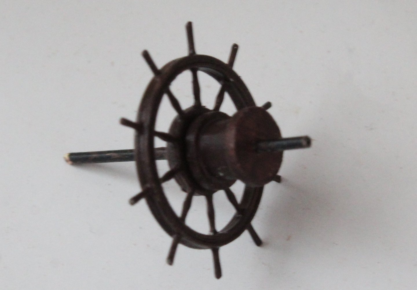
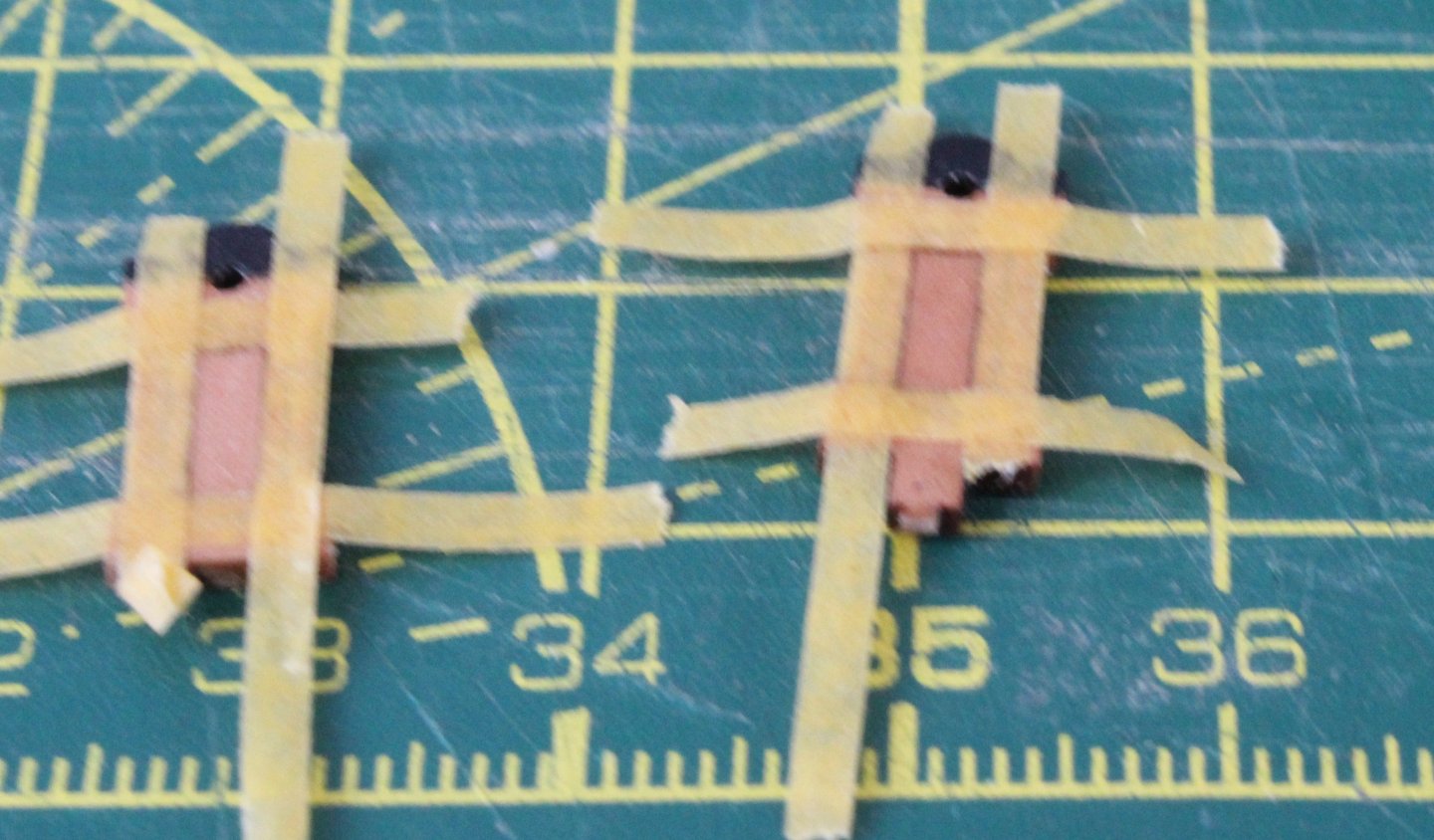
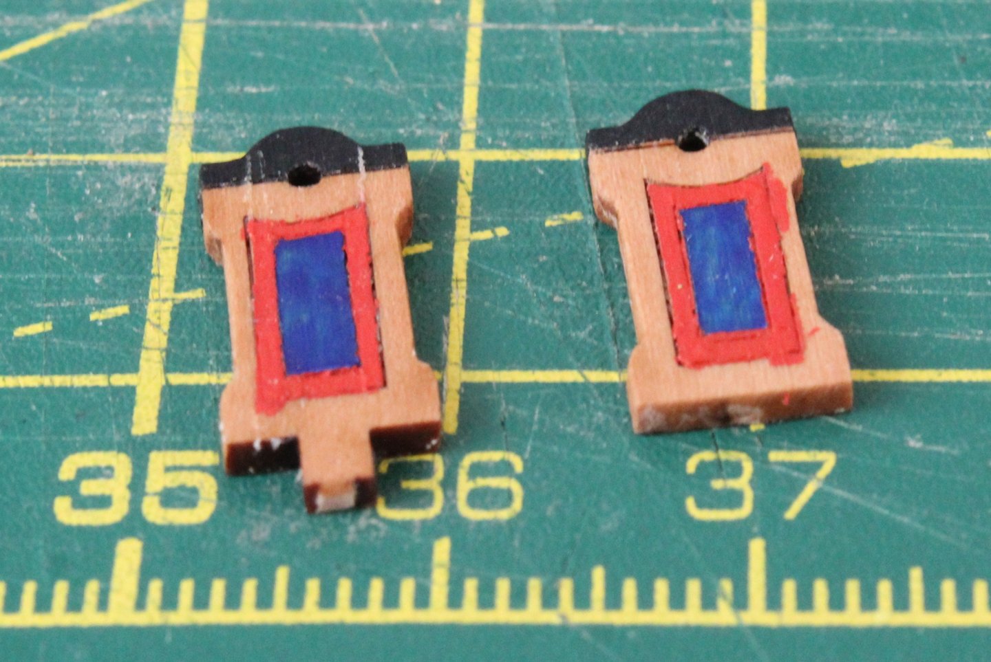
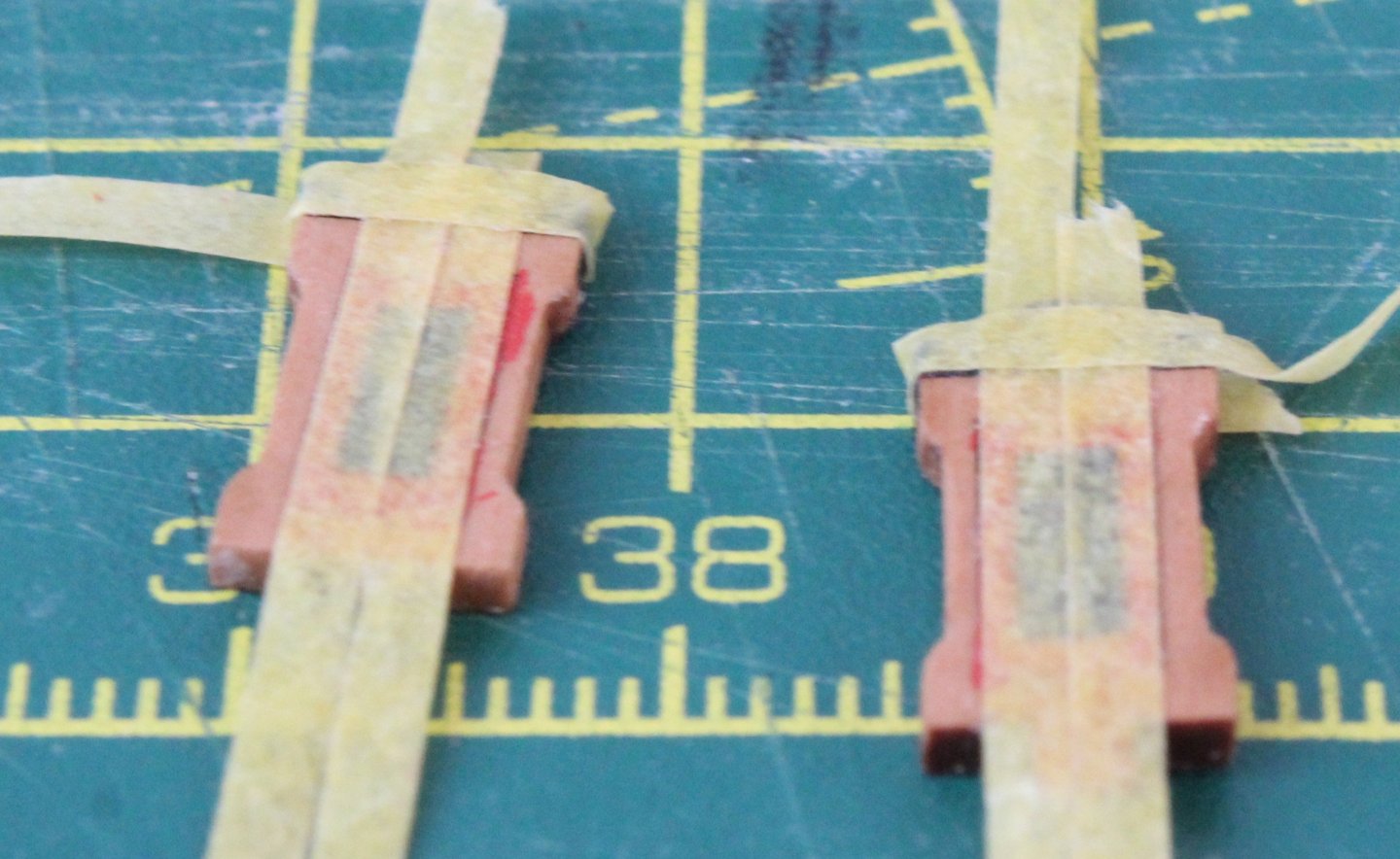
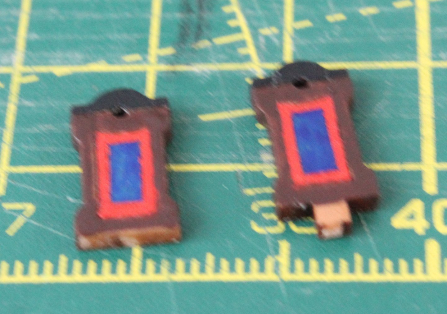
Build Log - Day 27 (10th & 11th Dec 2025) Task 46 – Ships Wheel My time in the shipyard is very limited this week therefore I am tackling some small tasks such as the ships wheel assembly. The ships wheel is made up from 5 PE parts which were glued together, using a 1mm rod to ensure everything was aligned. Next the cable drum assembly, comprising three wooden parts were glued together, once again using a 1mm rod to ensure everything was aligned. I then painted the drum and ship wheel a dark walnut colour, as can be seen below. The two end panels have nice some laser-etch lines and I decided, as this is a royal yacht, to embellish these with some paint. In the photo below I have taped the two panels so the centre section can be painted royal blue and the second photo shows the end result, noting I had already added black paint the top section. In the next set of photos more tape is used so I could add a red outline to the blue insert. More tape was then added so the external edges of the panels could be painted dark walnut. Test fit of the ship wheel assembly, noting the ship wheel assembly has not been glued together Task 47 – Main Rail Thoughts Before I glue the main rails in place I thought I would experiment with some different finishes. This is the current natural wood finish. It looks Ok but I think it would look better if it were a bit darker in colour. Gold, look nice but I am not convinced this is the best option but would fit in with the opulence of a royal yacht. Leather, this looks OK but I am not sure this colour really complements the red and blue. Dark Walnut, again looks OK but I think it is too dark.


-
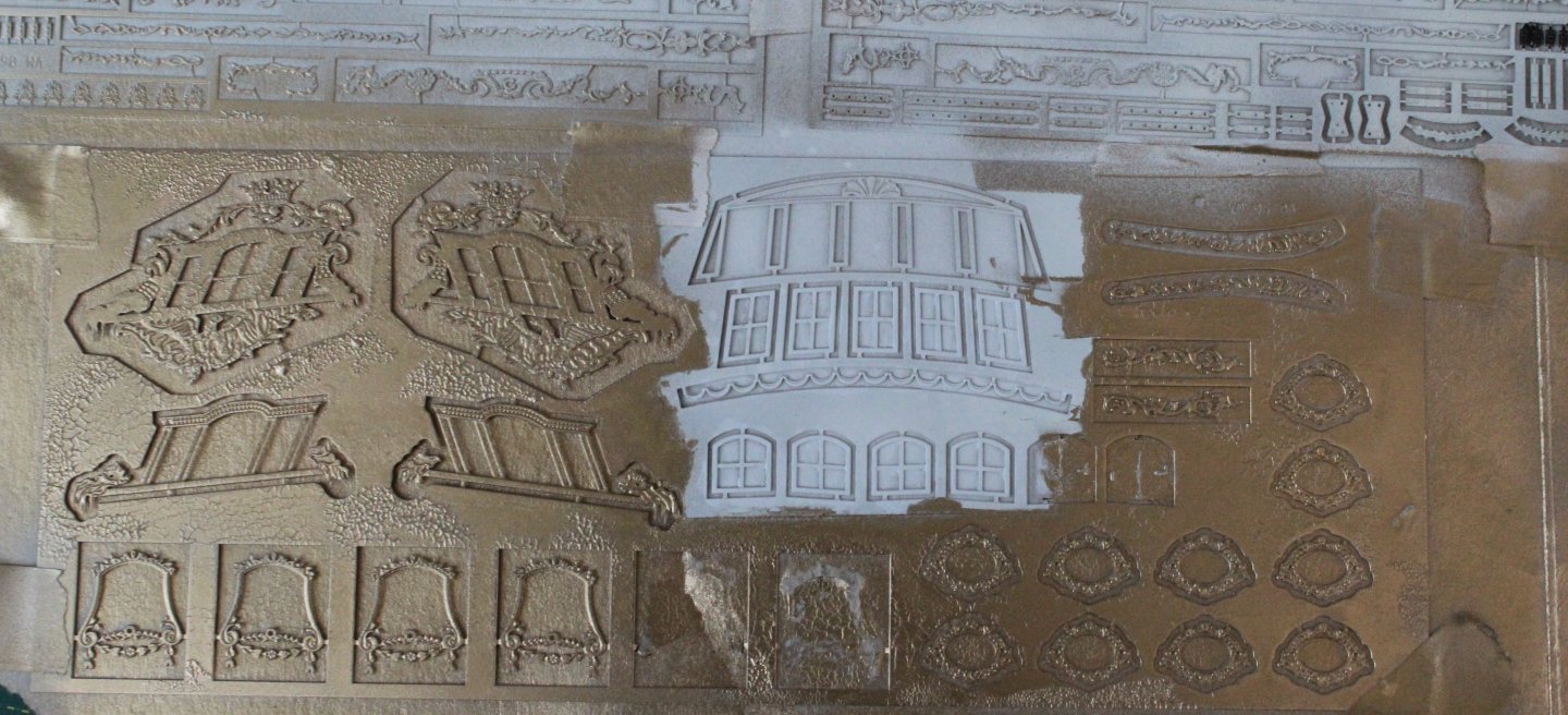
Build Log - Day 26 (9th Dec 2025) Task 45 – Mid Deck Bulkhead The first task today was to start preparing the various PE parts for the main rails and mid deck bulkhead. After cleaning I sprayed a white primer to the PE sheets. Once the paint had dried, I taped over the items which will be painted white and then sprayed the paints with a brilliant gold paint. The mid-section bulkhead comprises to wooden patterns which need to be glued together. However before doing this I embarked making this bulkhead fit for a Duchess. I painted the top section of the rear pattern royal imperial blue and the lower section walnut brown. The upper most pattern had a more complex painting scheme. The window section was painted black. The outer framework was painted red. The outer and inner door framework sections were also painted red, and the middle section was painted walnut brown. The door was painted imperial blue. Finally, I added a walnut brown finish to the frames for the 4 off inner door decorative panels. With the painting complete the two sections were glued together. I then added two eyebolts fitted with rings for the door handles (painted black). The window frames and window decorative patterns were then test fitted. I am really pleased with how this panel now looks and feel it was worth the time and effort taken. The right-hand window frame was dislodged when positioning the panel for the attached photo so it is slightly askew but will be fixed in place when the frames are glued. The door hinges also need to be added, which I have painted black. There is also a decorative gold painted PE part to add above the door frame.

-
With the introduction of 3D printed parts more depth can be added. For example, there is a nice 3D printed pattern which is added the stern with this kit
-
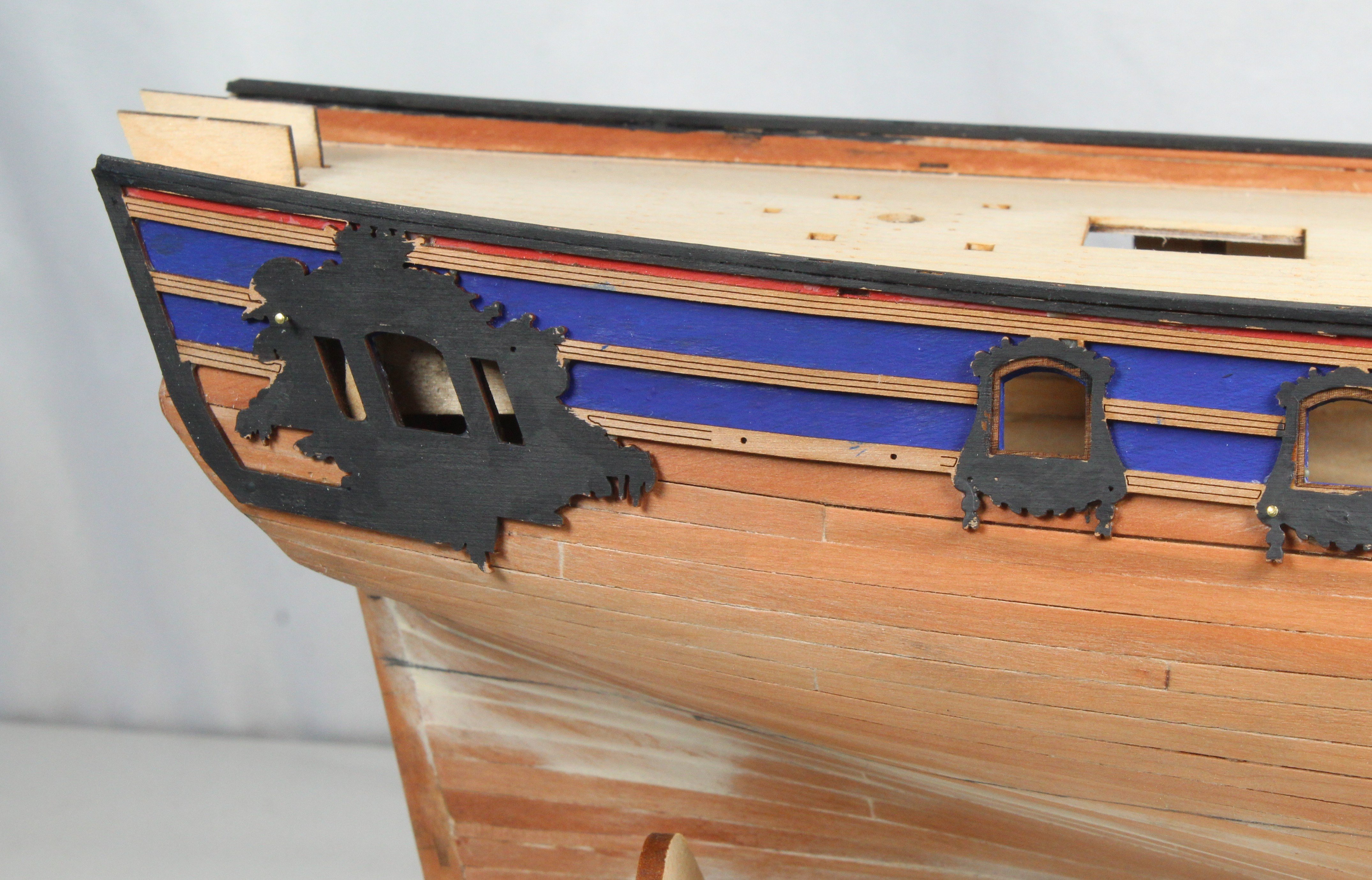
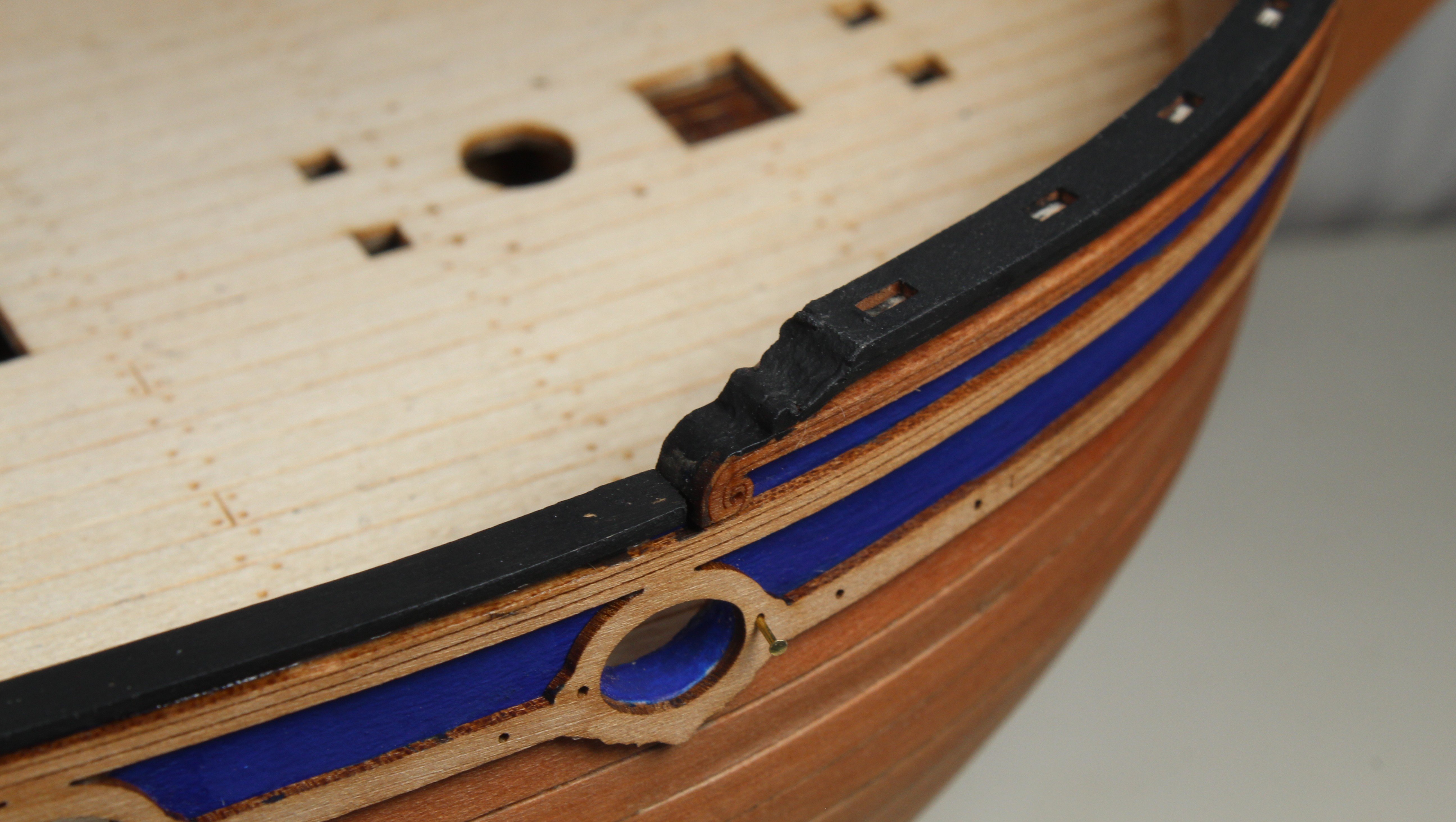
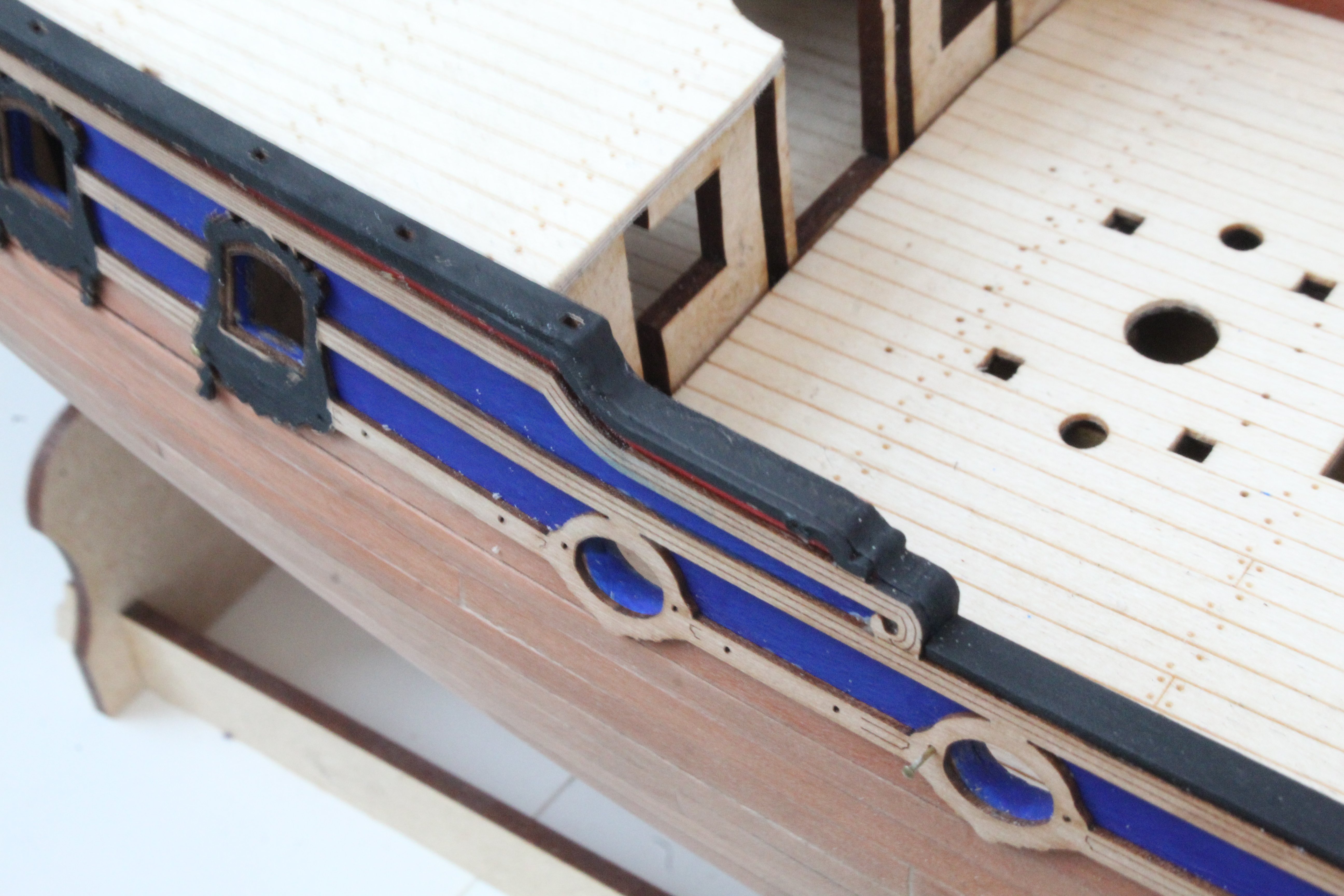
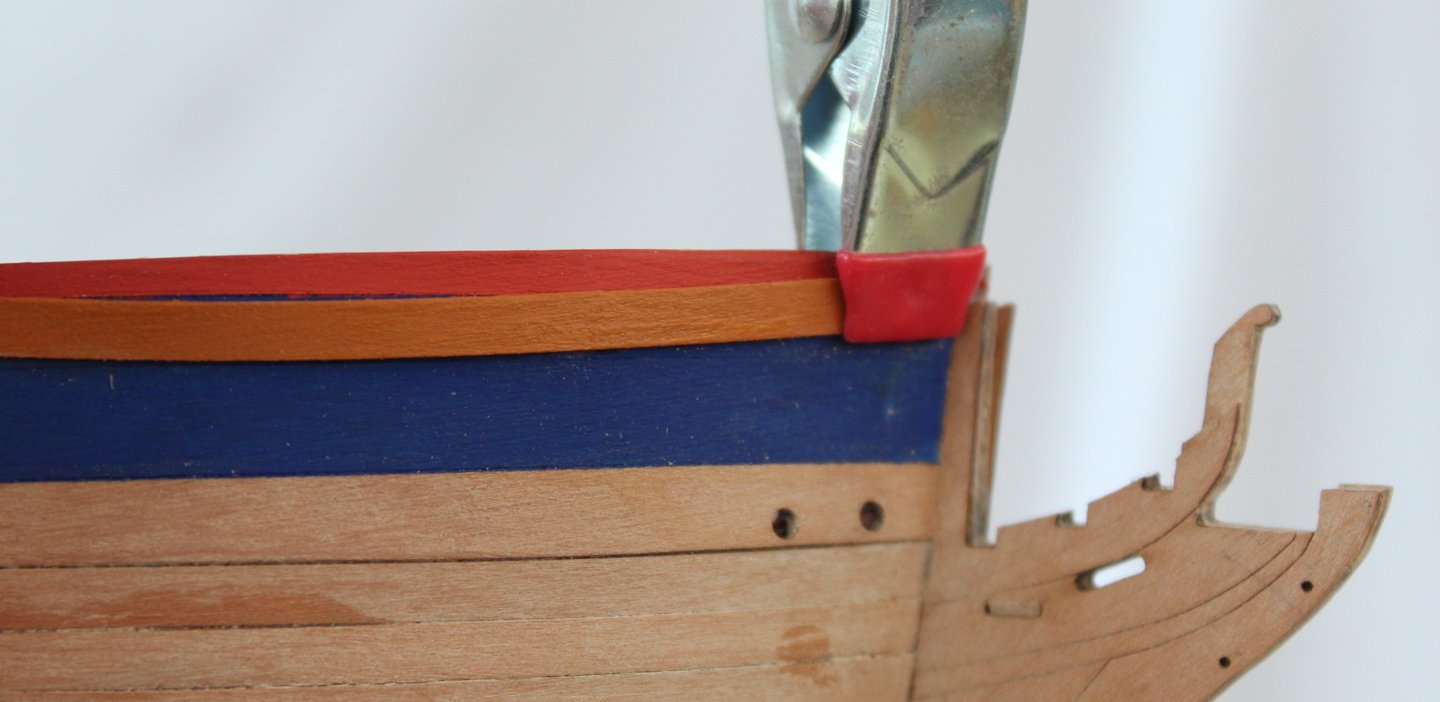
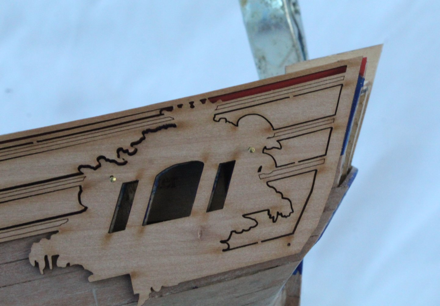
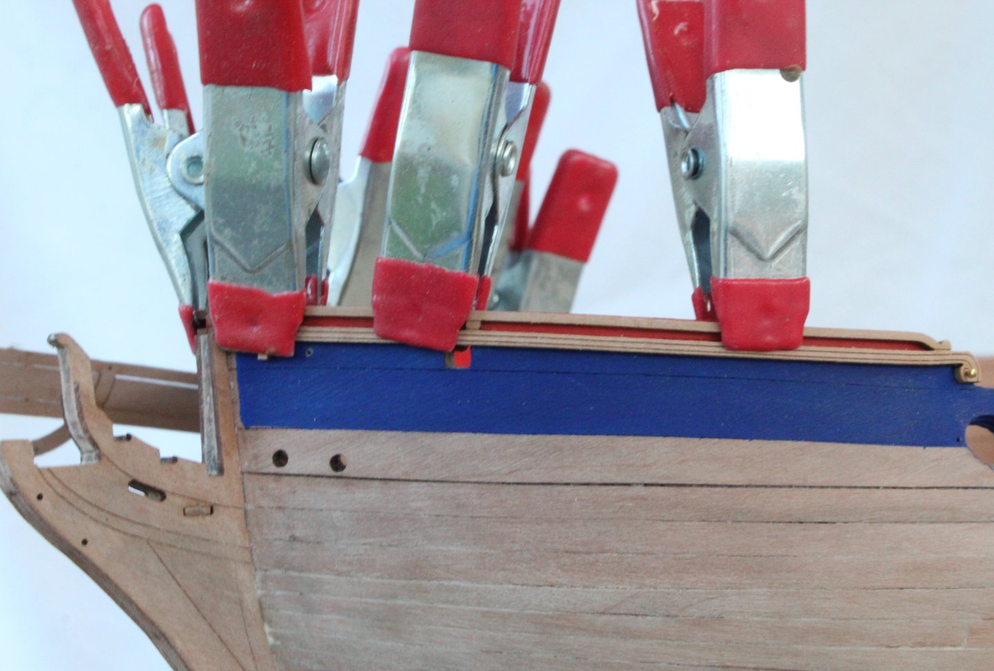
Build Log - Day 25 (7th & 8th Dec 2025) Task 45 – Main Rails Prep Work I am currently doing some more prep work this time related to the main rail patterns as it is important to get a good fit with these decorative patterns. When test fitting the main rail it can be seen that stern frame counters still need to be trimmed so they are flush with the end of the main rail. I marked the end position of the main rail pattern on the hull and then with the patterns removed, using some different grit sanding sticks, the stern frames were sanded to the marked lines. I did manage snap off the four dangly bits from the two rear window shapes on the right-hand main rail pattern when removing the laser char so it may take me a bit of time to sort out before that part can be fitted. After carefully removing the laser char the bow main rail patterns they were soaked in hot water and then clamped to my bending jig (see earlier posts regarding the jig). Once the patterns had fully dried (after 18 hours) they were test fitted and were a good fit. The next set of photos shows the test fit of the main rail patterns. They do look nice. I will have to trim the bow section of the lower main rail patterns, so they fit flush with the stem post. The bow gunwale patterns did need a slight adjustment to the curve at the bow end, so they accurately follow the curve of my hull. The patterns were soaked in hot water for 30 minutes and then clamped to get the required new curve. Once the clamps were removed I was happy with the fit. I also test fitted the midship and upper deck gunwales and I was happy with how they looked. I am also adding a slight lateral bend to the rear section main rail so it follows the curve of the hull, as can be seen below.


-
It is AK11180 Imperial Blue, acrylic. The red is AK11092 Matt Red acrylic. The wood colour is Admiralty paints AP9119W (walnut). Not sure why I said oak and I have updated my post accordingly.
-
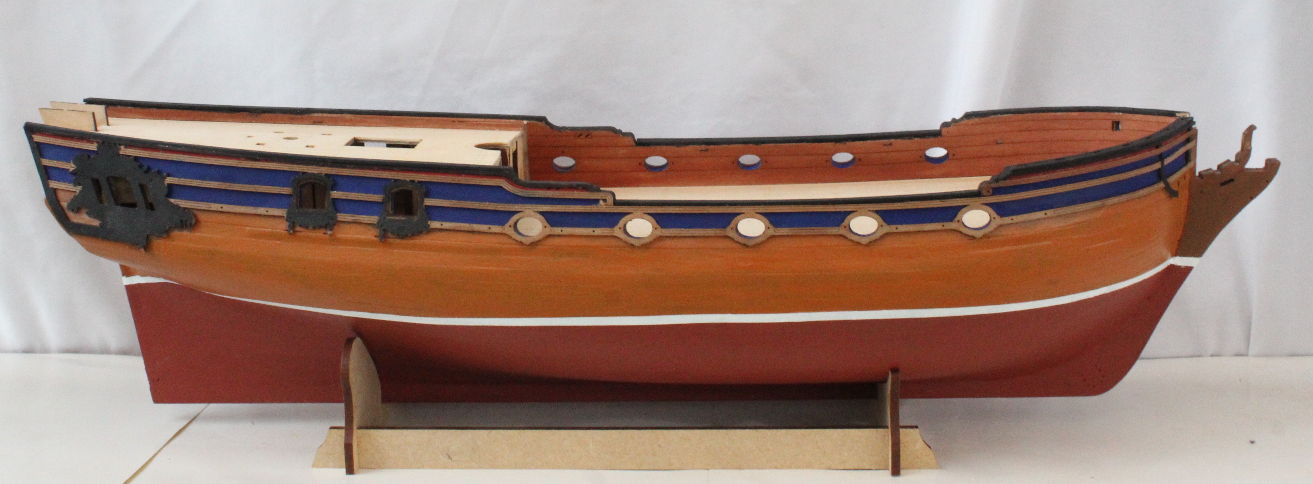
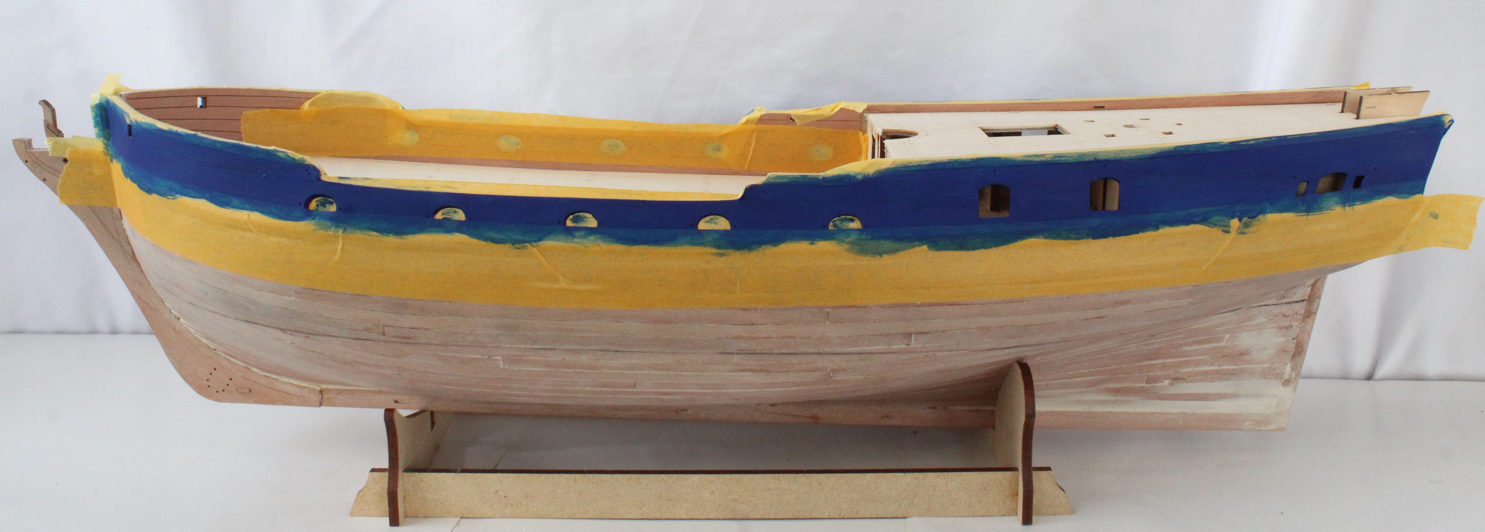
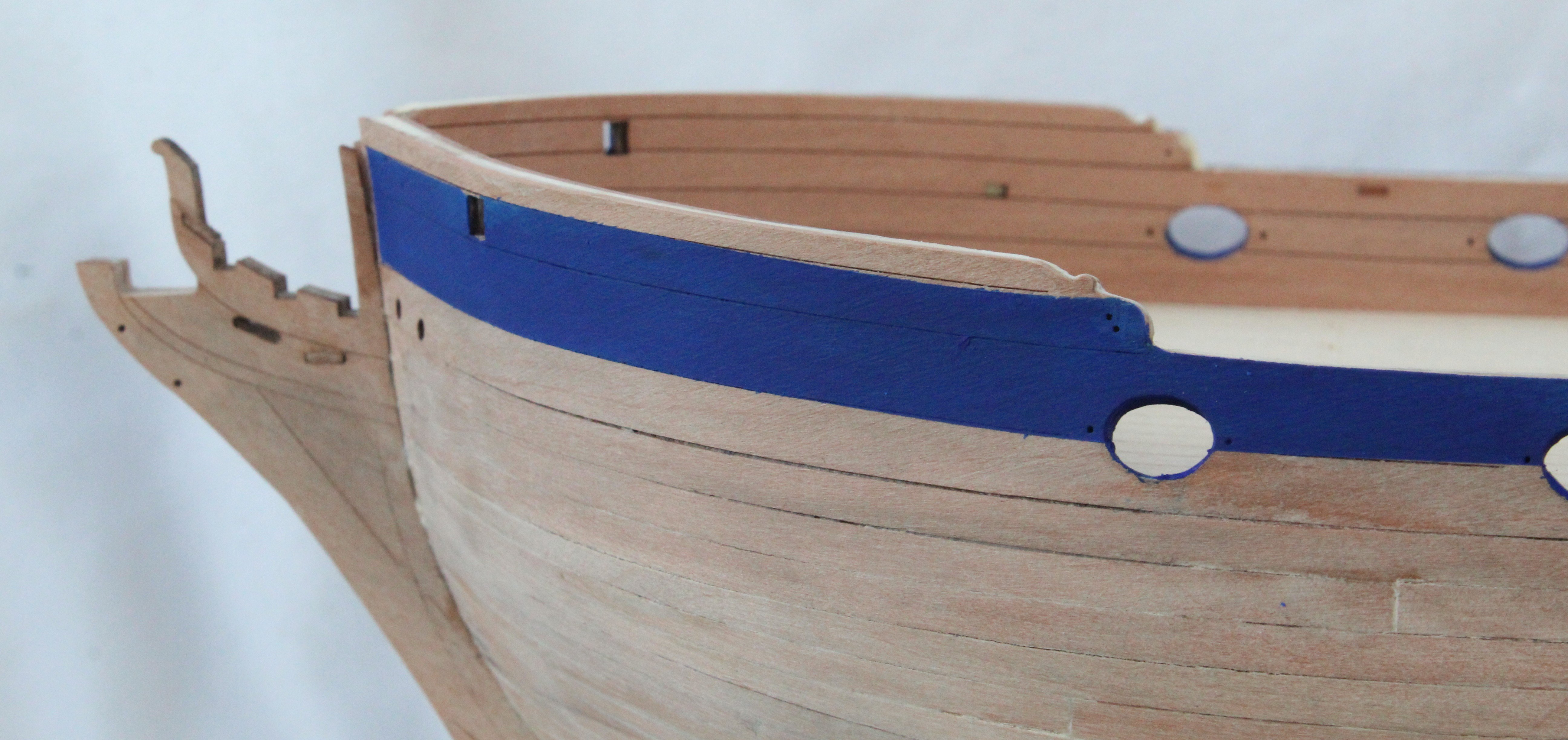
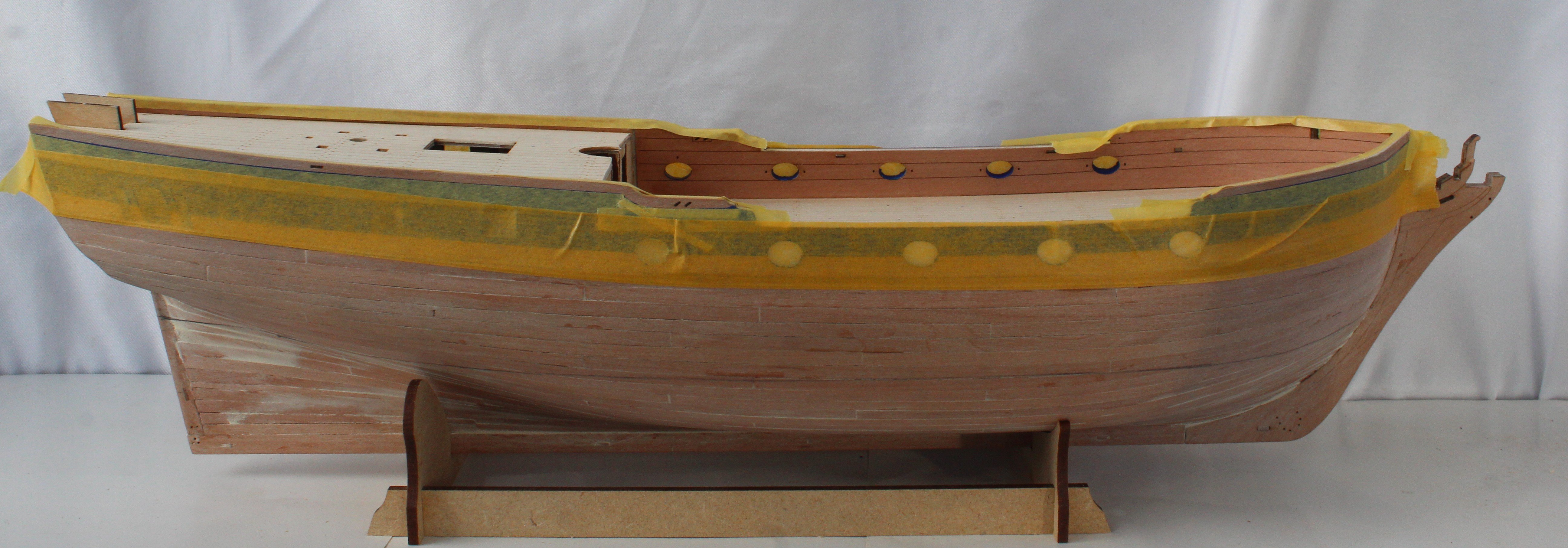
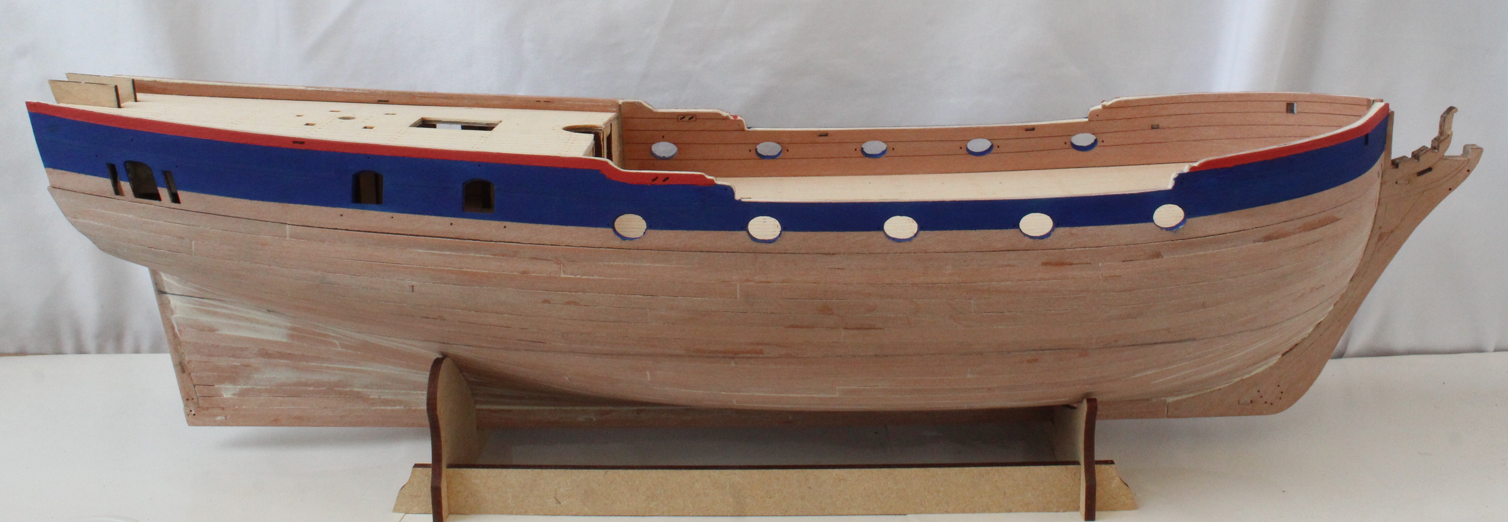
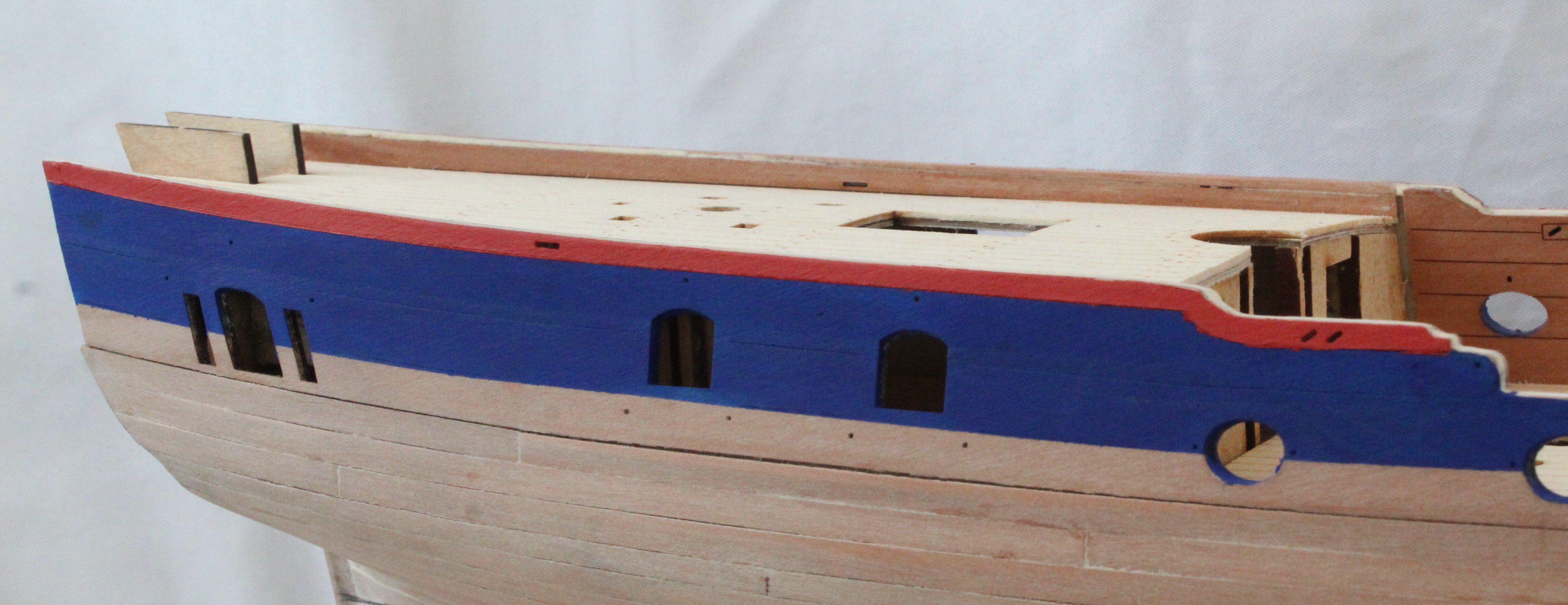
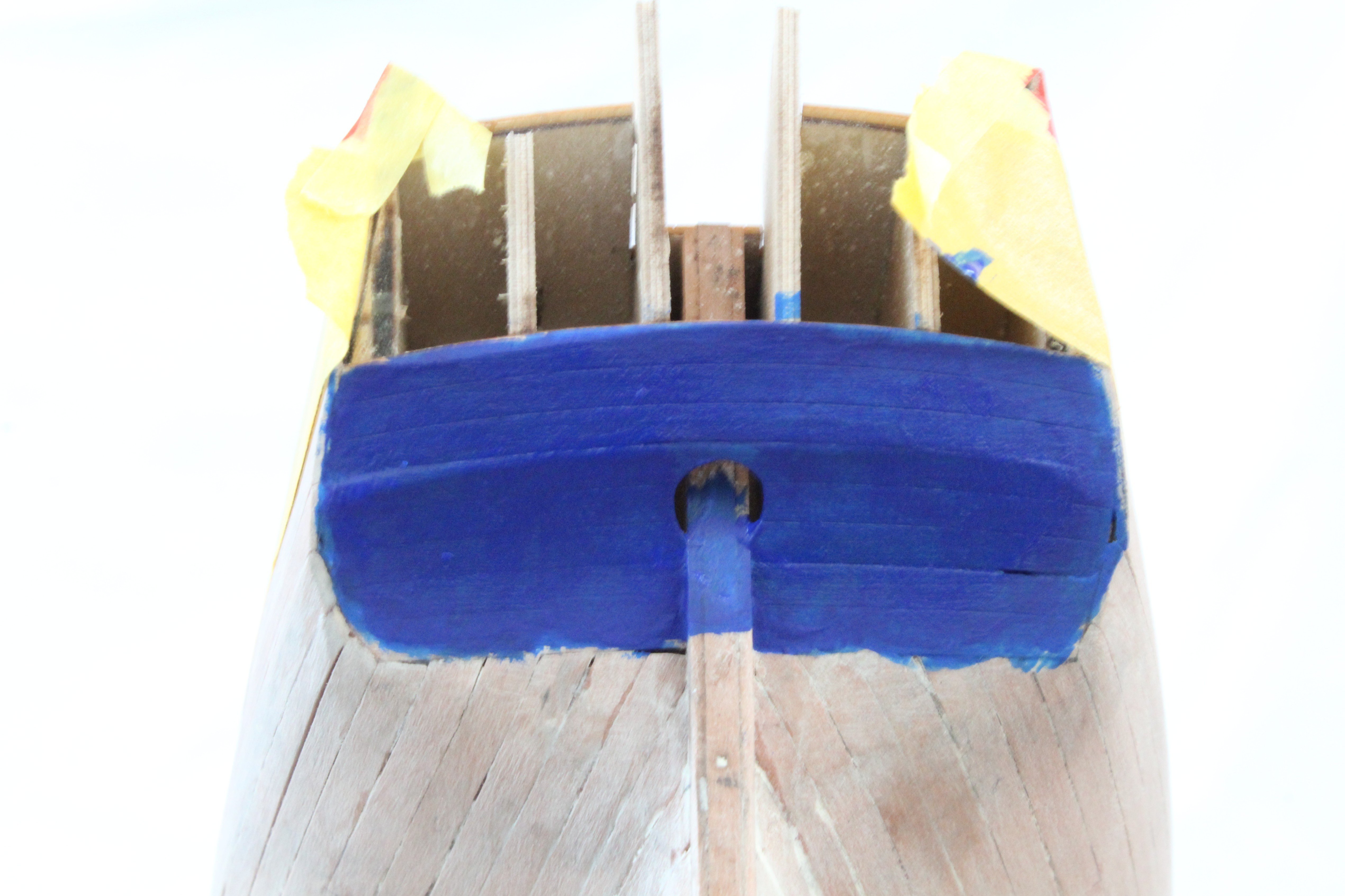
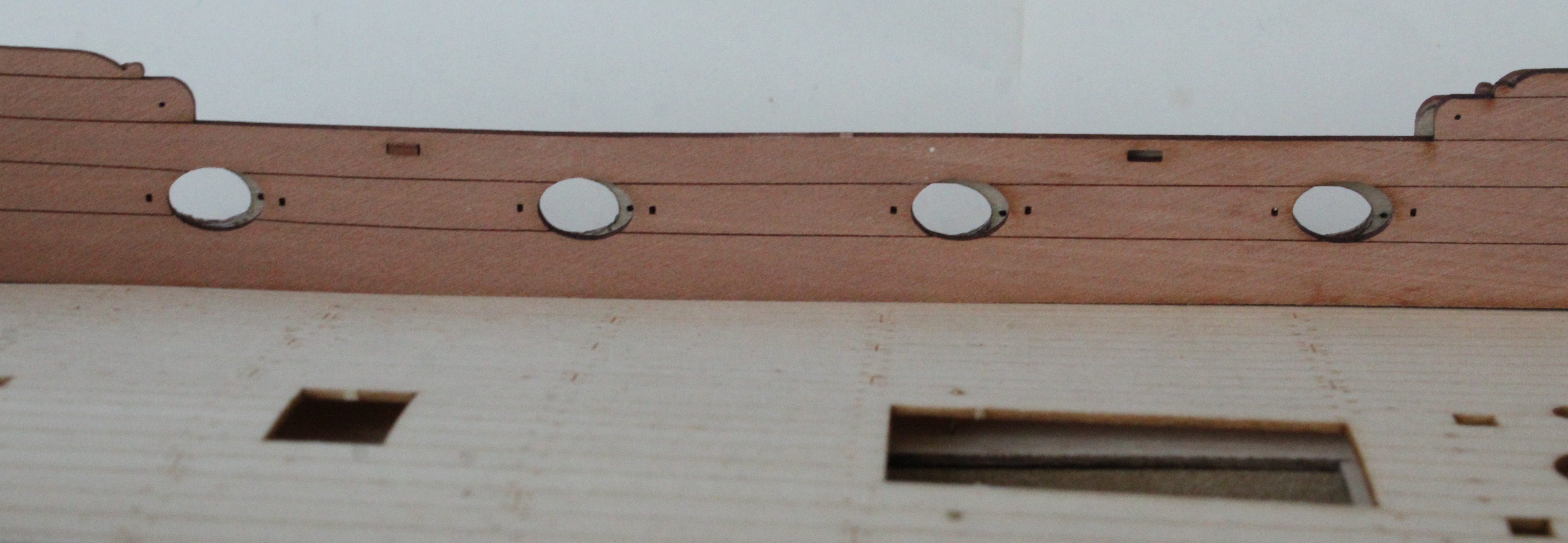
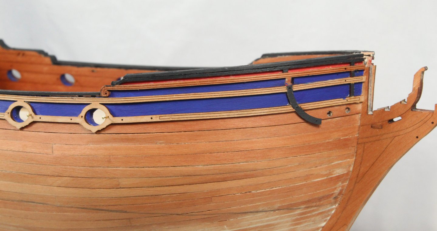
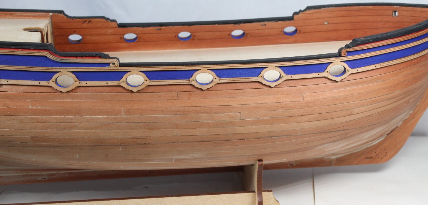
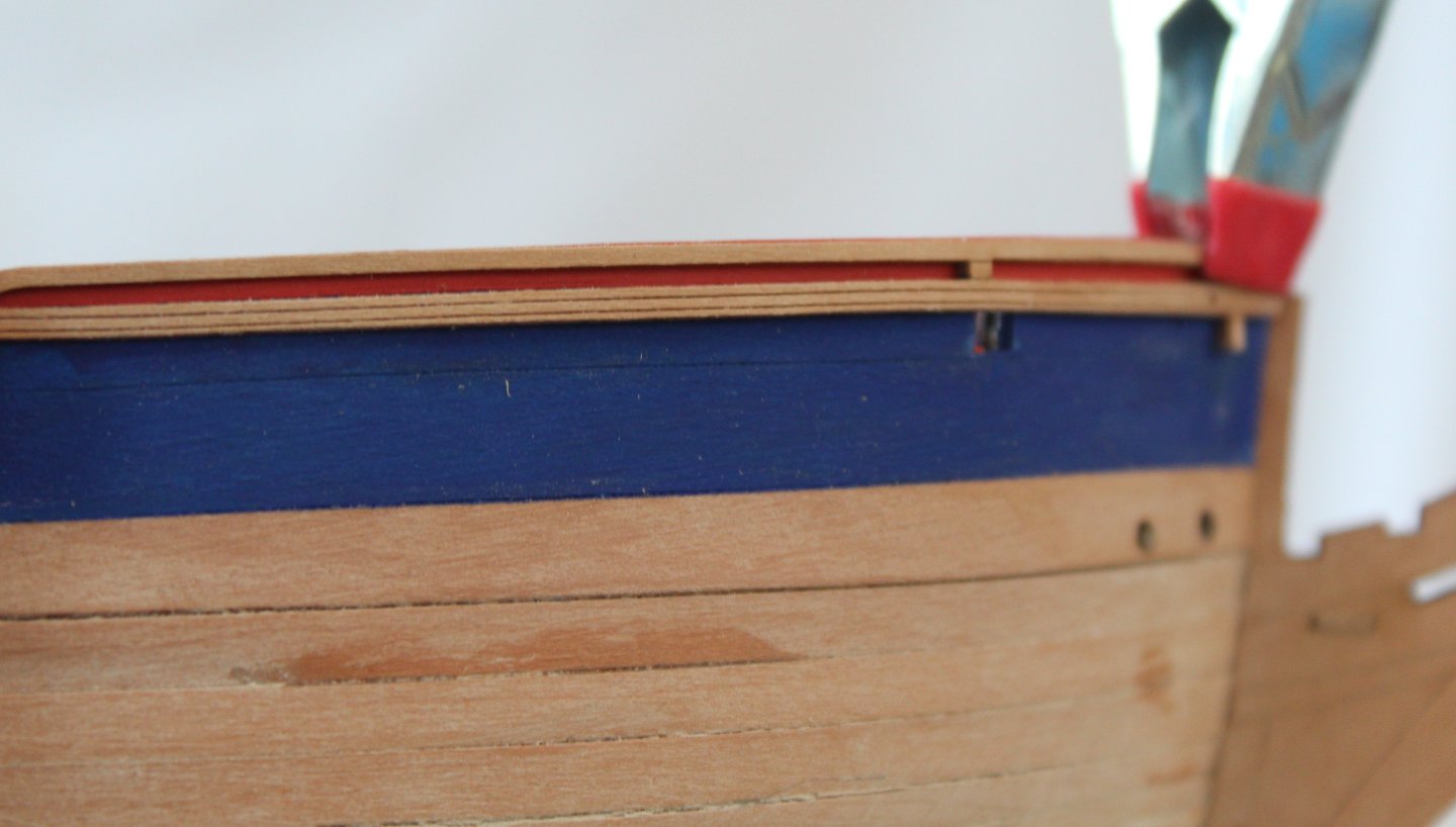
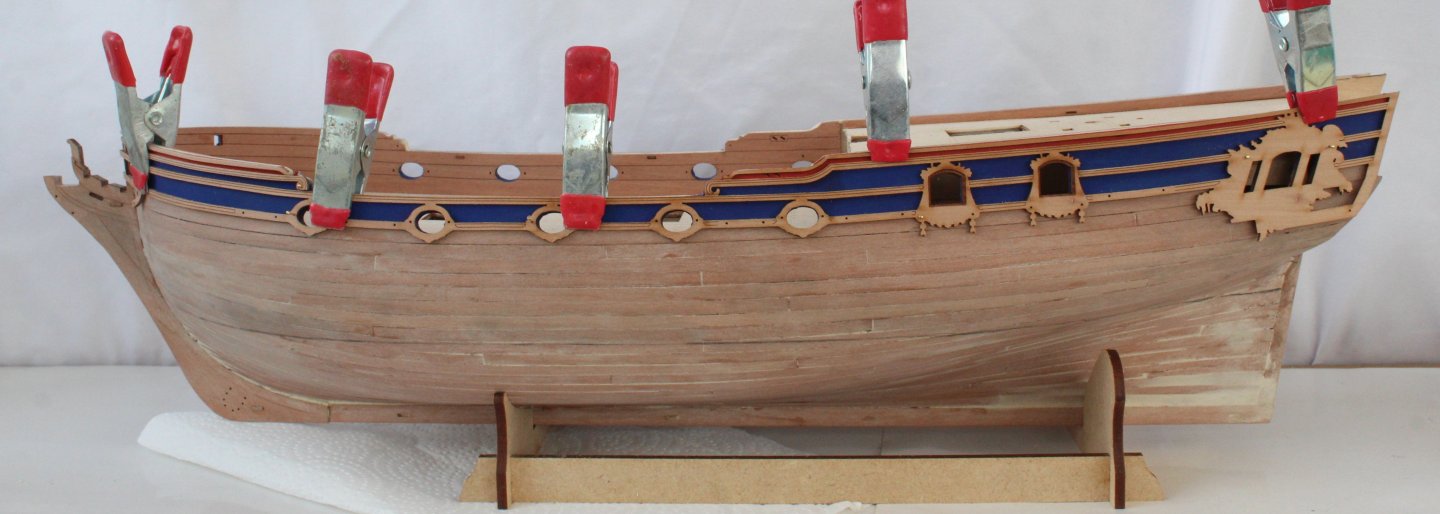
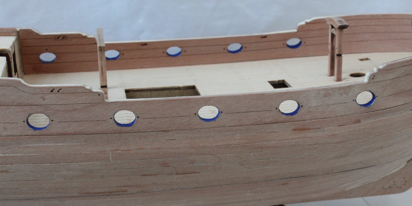
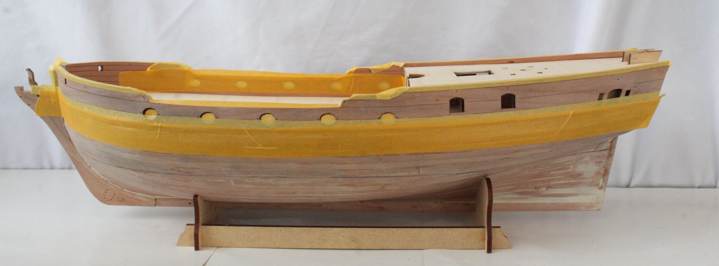
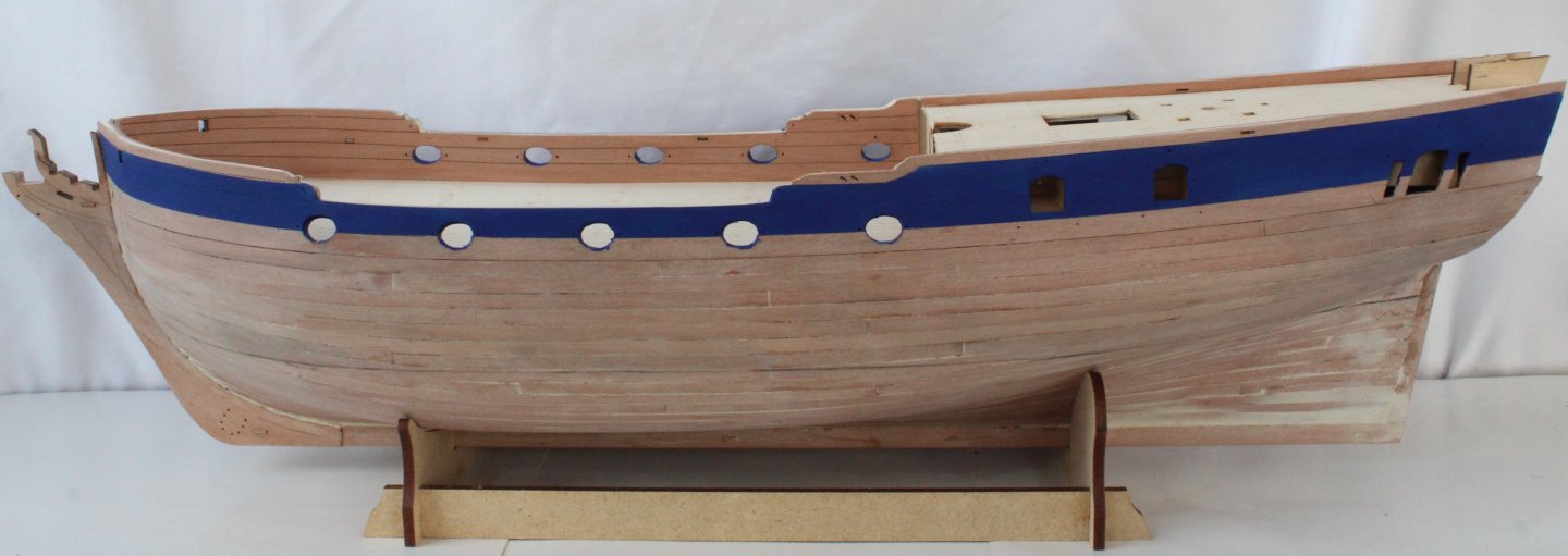
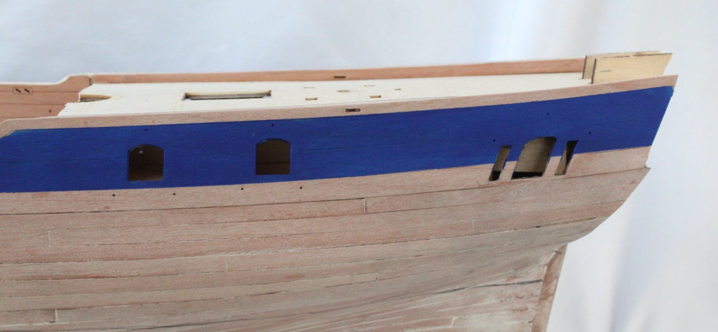
Build Log - Day 24 (5th & 6th Dec 2025) Task 44 – Painting The Hull The first task was to apply a WOP finish to the hull, inner bulwarks, stern counter and decks. I used a 50 / 50 mix of Rustins Clear Satin polyurethane and white sprit for this. Two coats were applied. Next the gunport oval openings were painted blue. Tape was attached to the inner bulwarks to prevent leakage. Next the hull was taped up so the blue band could be painted. I brushed on 4 coats of diluted blue paint. The tape was then removed and new tape added so the red paint band could be added. I brushed on 4 coats of diluted red paint. The lower stern counter was also painted blue. Photos Gun Ports Painted Hull taped and ready for the blue paint Hull after blue paint has been added Hull taped and ready for the red paint Hull after red paint has been added. Rails will be added which will hide and paint overspills between the colours. Stern counter painted. Rails will be added which will hide the paint overspills with the hull below the stern counter. Testing different wood-coloured paints which I might use on the hull. I am currently drawn toward the right hand walnut wood colour.


-
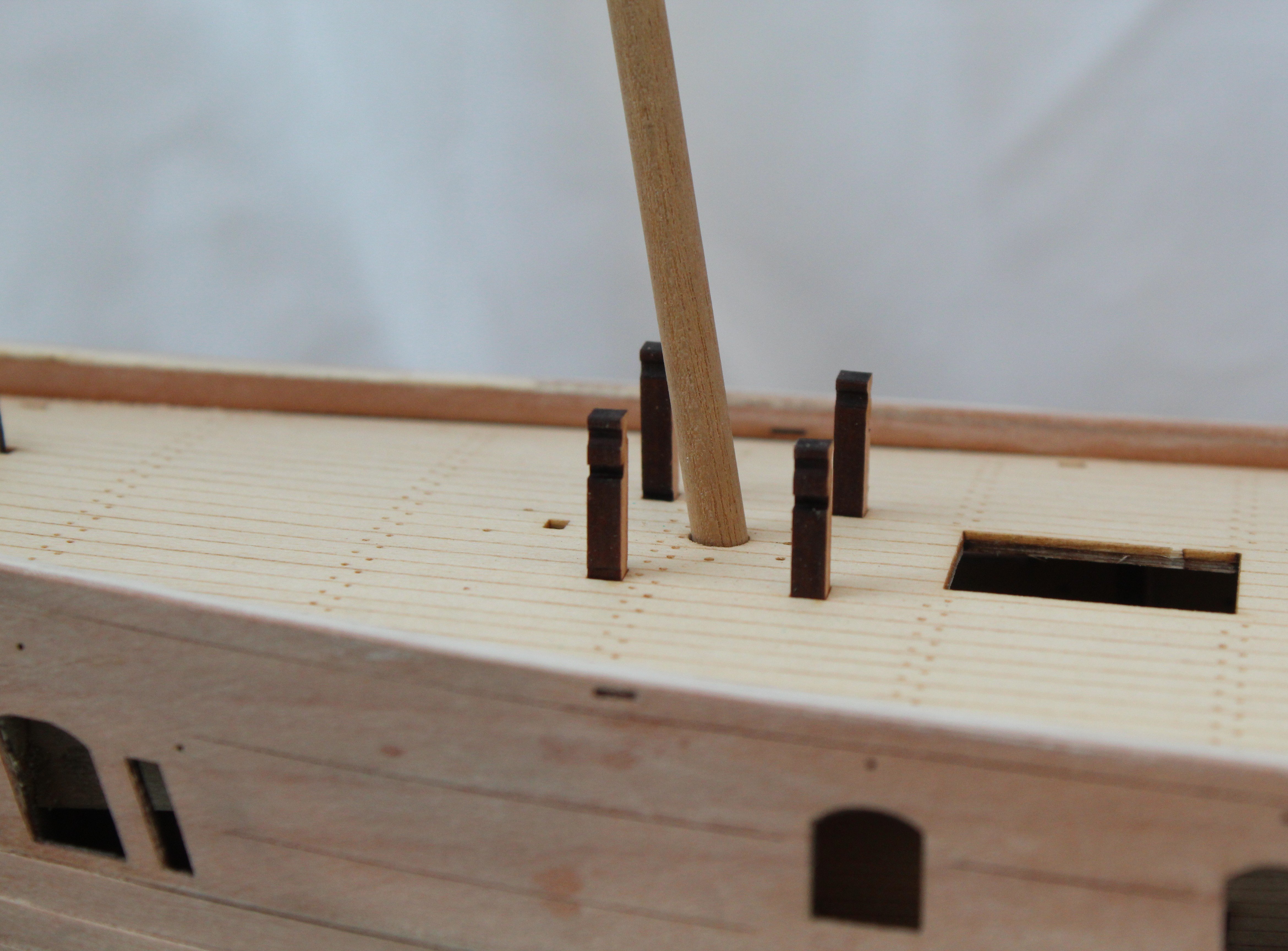
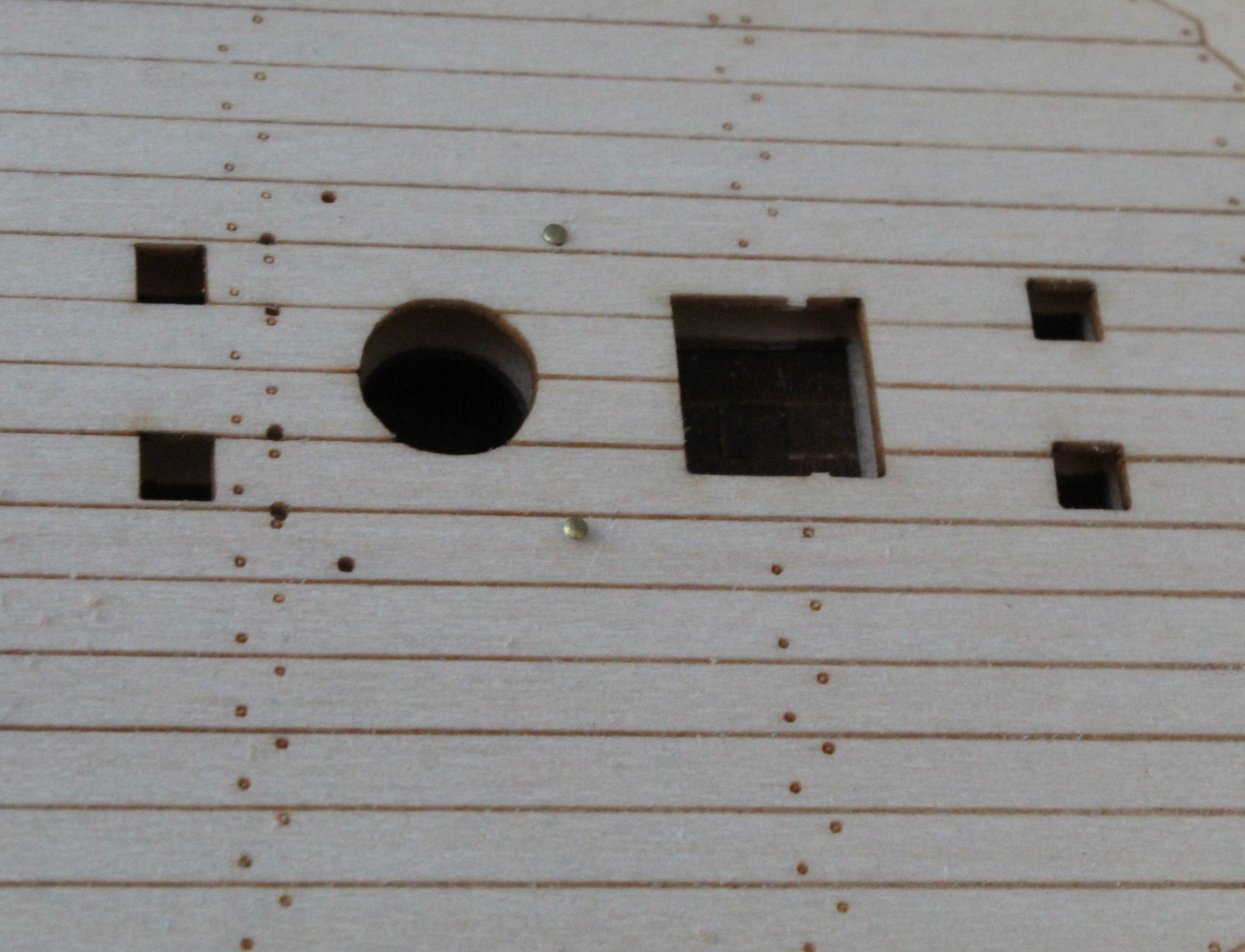
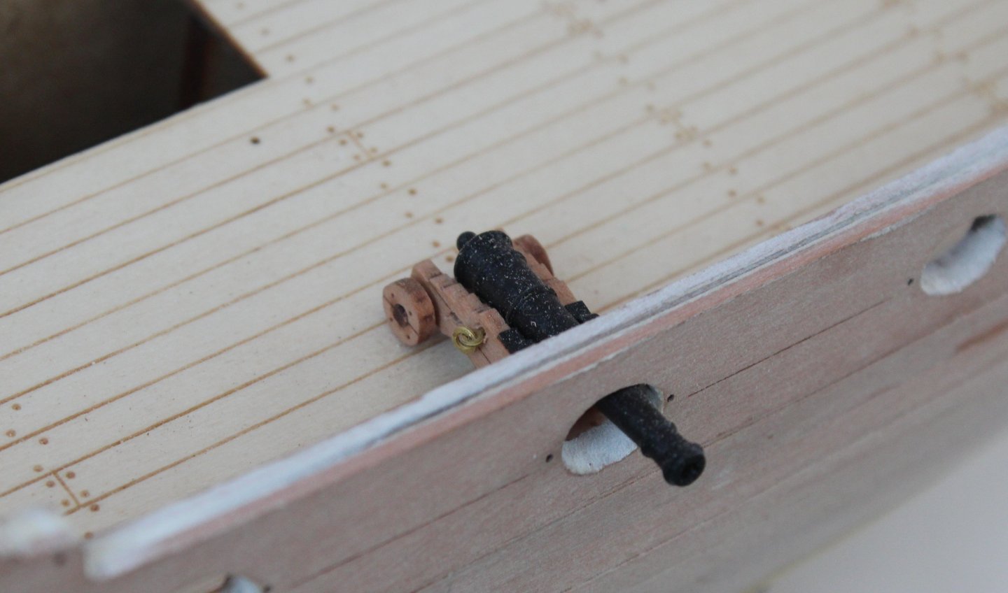
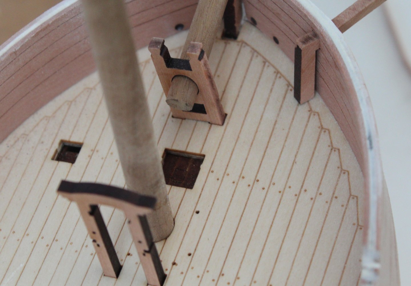
Build Log - Day 23 (3rd Dec 2025) Task 43 – More Prep Work I have now sanded the tops of the bulwarks level and did test fit the gunwales. All looks good. I did brush on some diluted wood filler around the curved sections that are not covered by the gunwales so the laminations between the layers will not be visible once painted. The gunport opening were also sanded smooth and coated with diluted wood filler so that, when painted, the laminations between the layers should not be visible. I copied this method from @DelF. I am currently waiting for a delivery of some Rustins Polyurethane clear satin varnish so I can apply a WOP finish to the hull before embarking on the painting tasks. I have also ordered some different coloured paints. Depending on the test results I might then paint the hull and inner bulwarks with a wooden paint finish. I also took the opportunity to test fit some of the deck items which locate in the various deck openings. Thankfully no problems detected. Photos Picture of the hull with some deck items, masts and bowsprit test fitted. Gun ports sanded and coated with diluted wood filler. Checking a cannon with a gunport Checking the bitts and mast on the upper deck Checking the cabin pattern, main mast and bitts Checking the foremast, bowsprit and bitts.


-
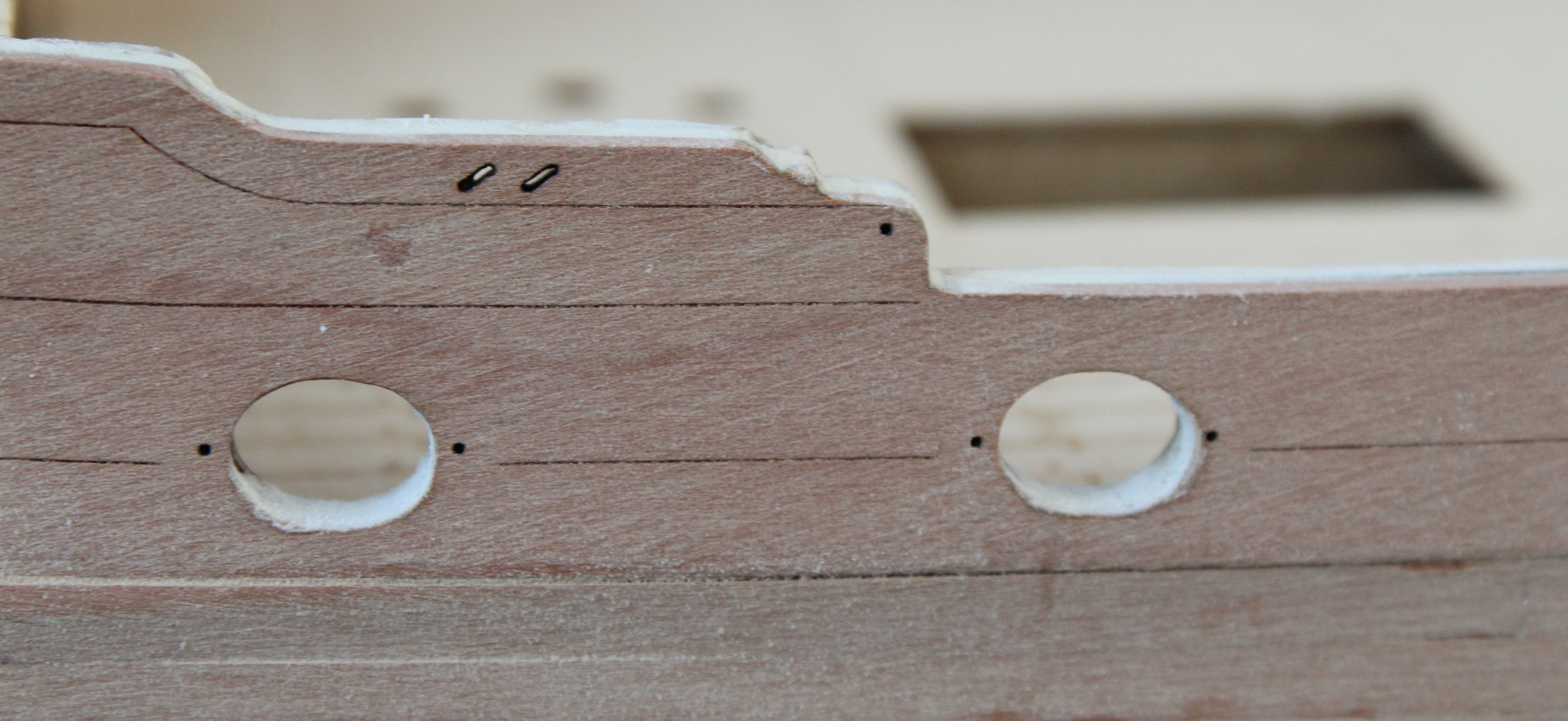
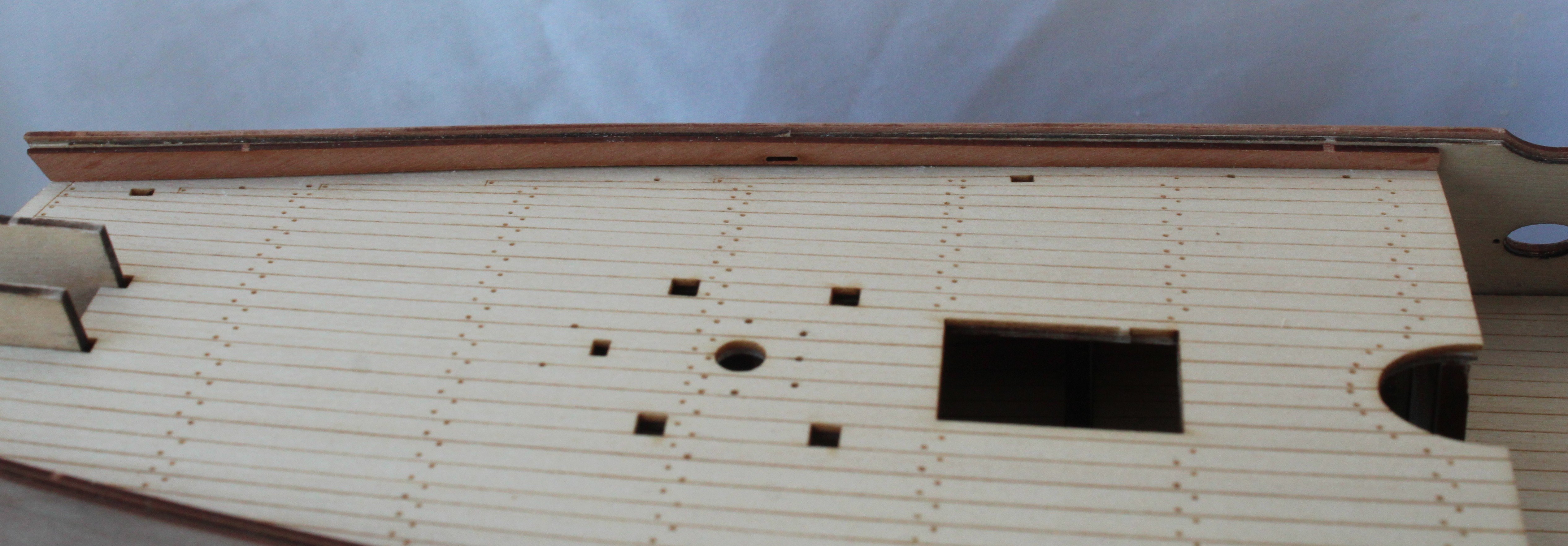
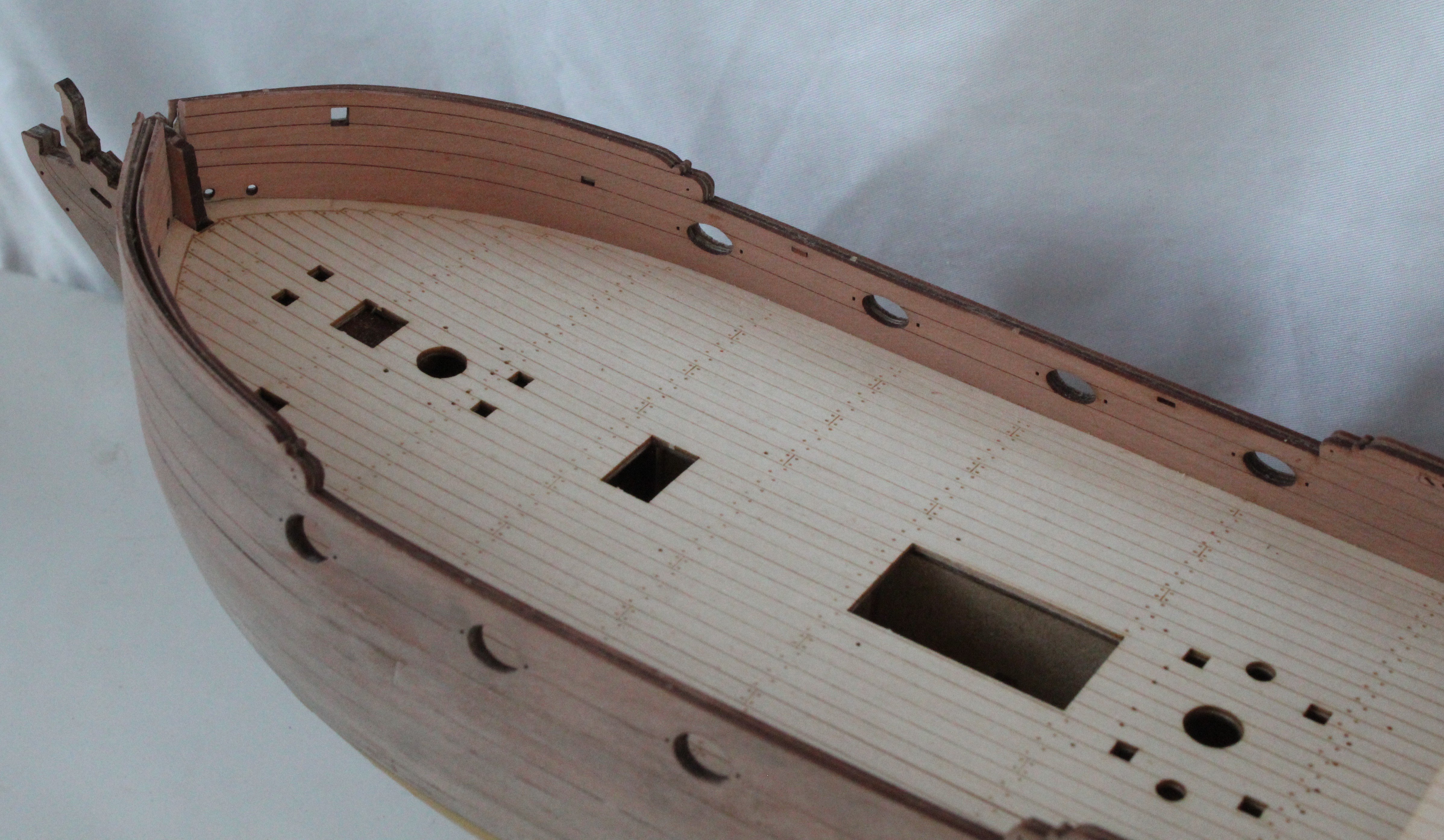
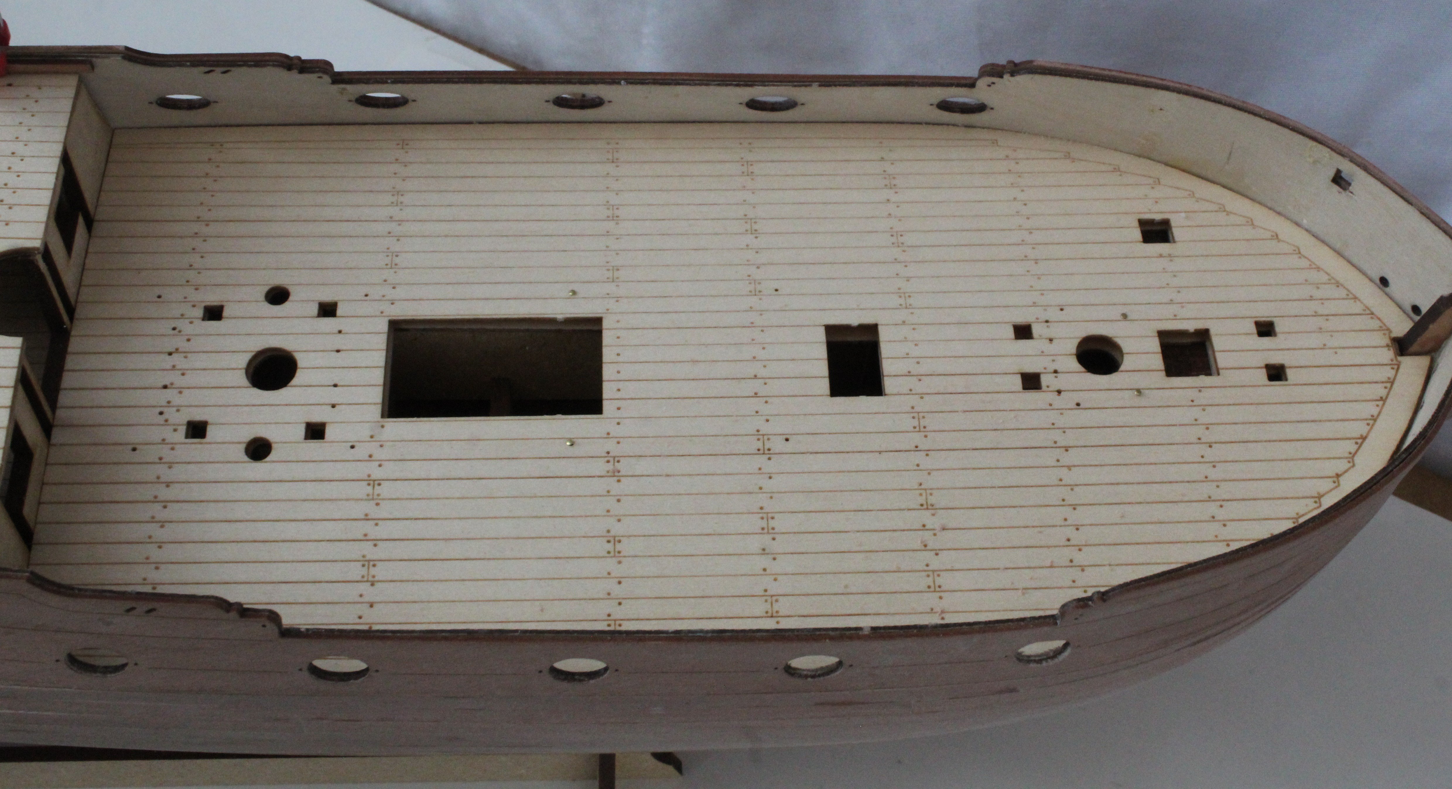
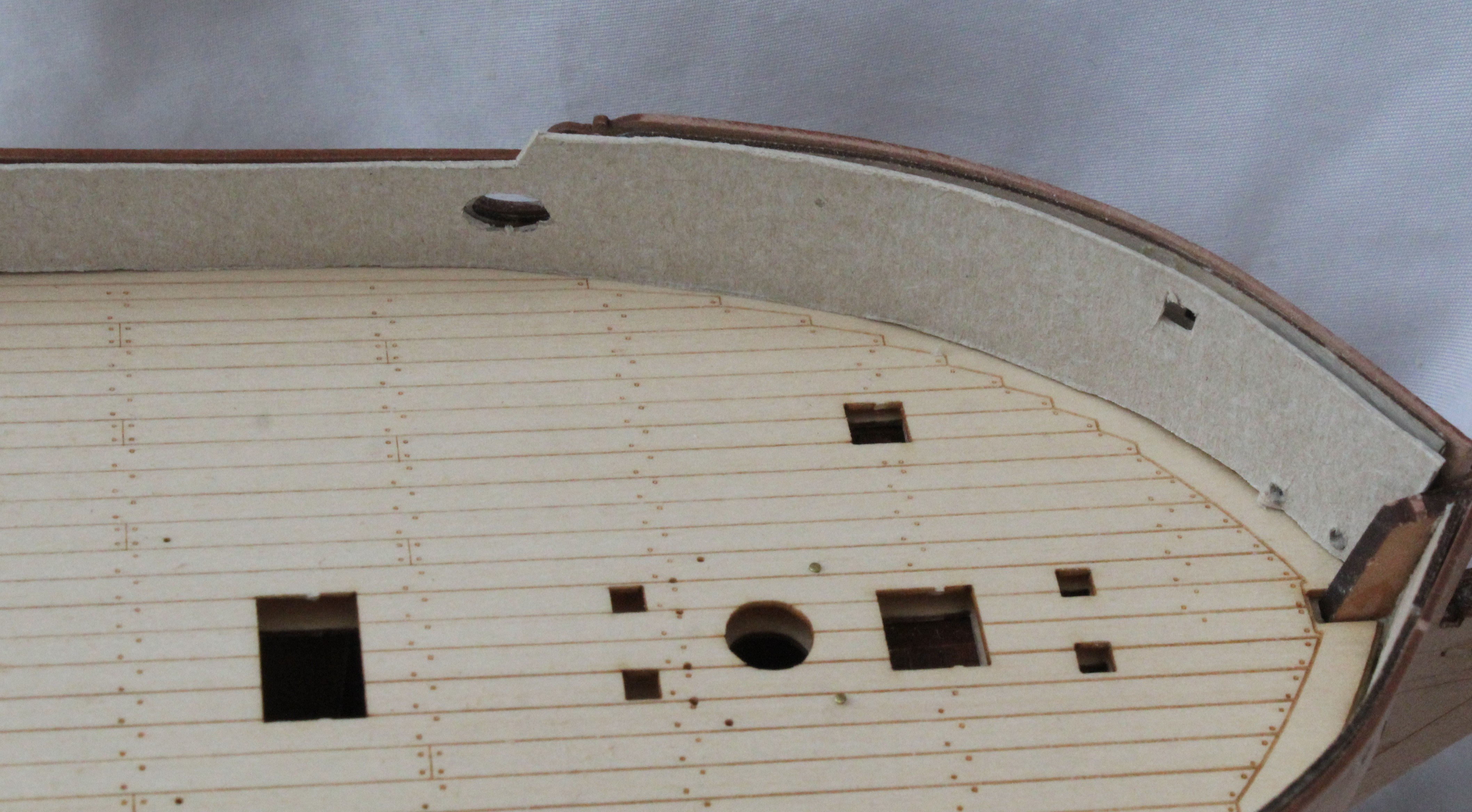
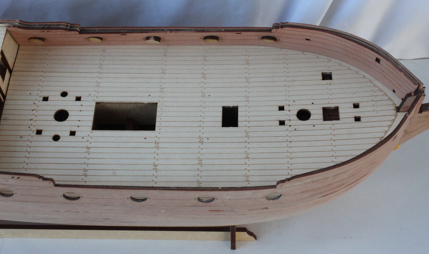
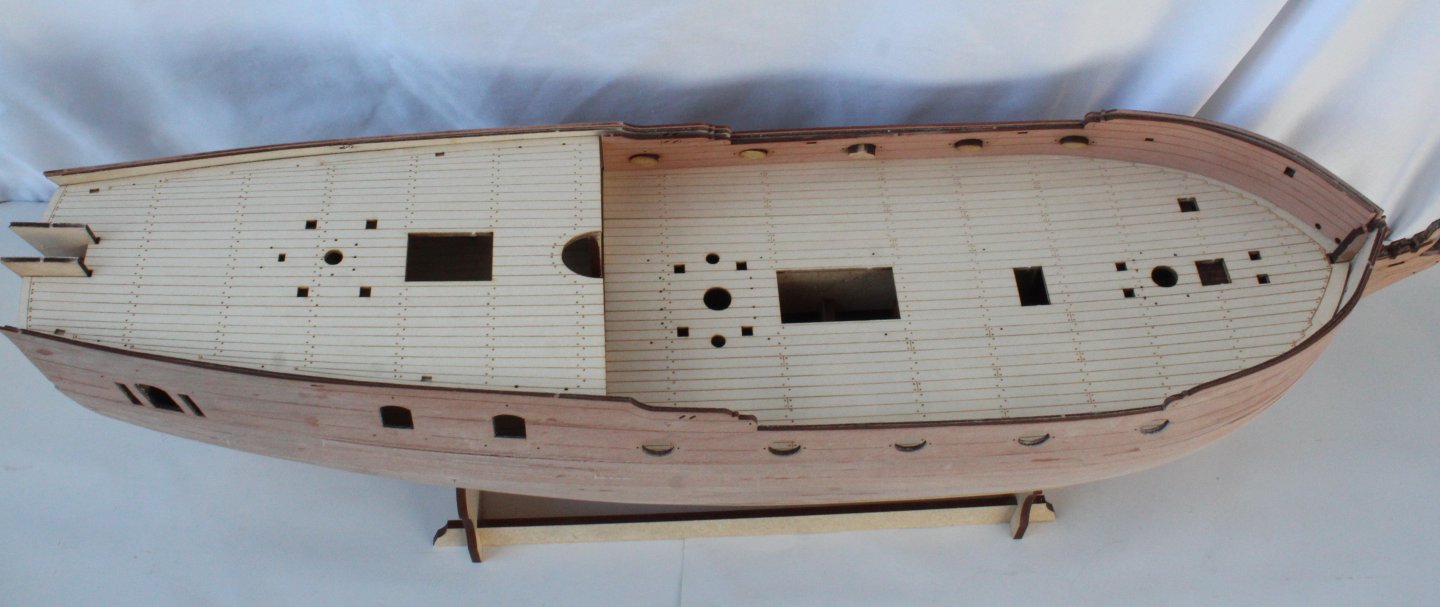
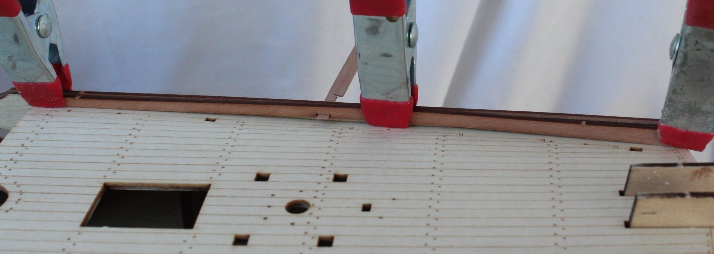
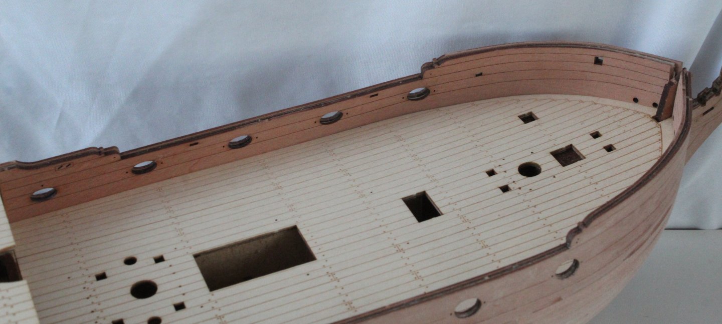
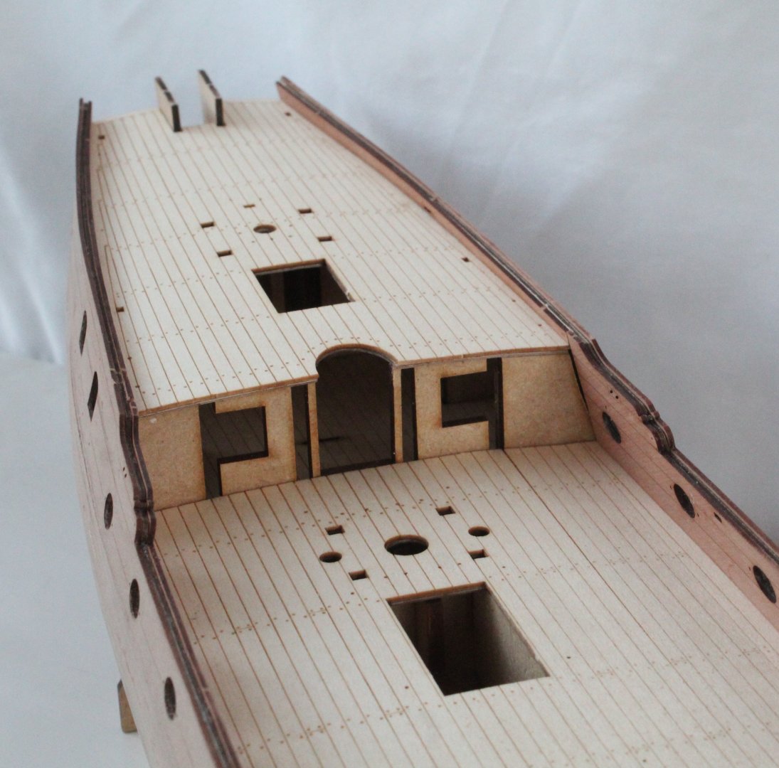
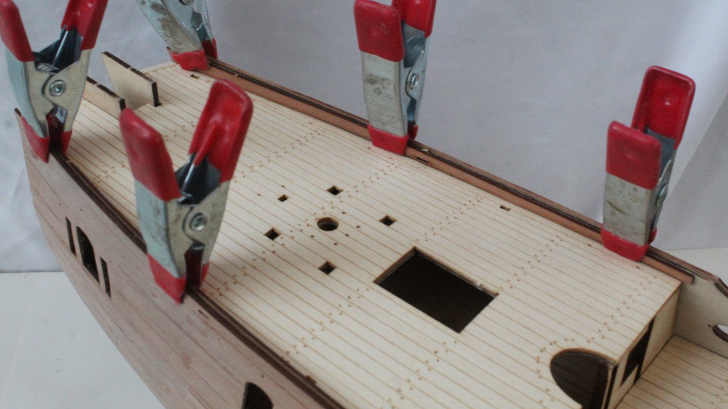
Build Log - Day 22 (2nd Dec 2025) Task 42 – Laser Etched Decks and Inner Bulwark patterns It took a few attempts before I was happy with the dry fit of the lower deck inner bulwark patterns. I ended up taking about 1mm from the front edge and then I had to sand a bit from the bottom edge. When test fitting the patterns I used both the cathead and the oval locator plugs to check the alignment. The two laser etched deck patterns were then glued in place. I used some pins pushed through the eyebolt holes to make sure these patterns were aligned with the deck bases. When test fitting the upper deck bulwark patterns I noted, when properly aligned, there was a gap between the bottom edge and the deck in the mid-section. I did consider making some new patterns, but I decided to sit these patterns flush with the deck when they were glued in place. The lower deck inner bulwark patterns were then glued in place. I used the catheads and oval locator plugs to position these patterns before clamping. Once clamped the catheads and locator plugs were removed. Photos Lower deck trial fit with bulwarks Laser Etched Decks Fitted The next photos shows the mid-section gap when the upper deck inner bulwark is aligned. Upper deck inner bulwark glued in place, without the gap with the deck. The lower deck inner bulwark pattern clamped in place after gluing. The oval locators were removed after this photo was taken. You may also note that I have drawn and taped the preliminary water line The current build status


-
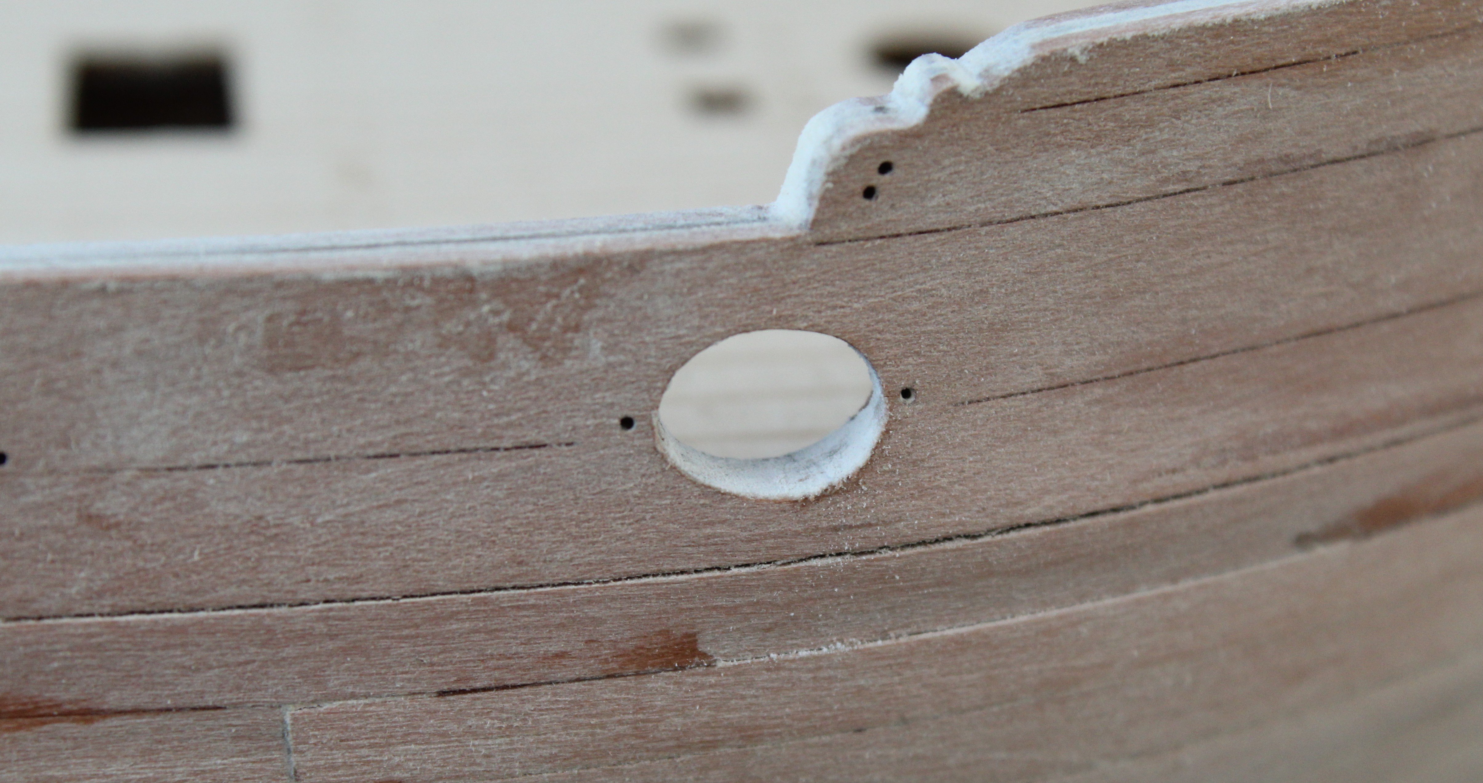
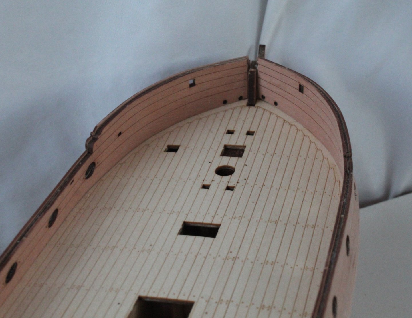
Build Log - Day 21 (1st Dec 2025) Task 41 – Prep for adding Laser Etched Decks and Inner Bulwark patterns It will take me a few days to complete the next task of adding the two laser engraved decks and associated inner bulwark patterns. The first task was to remove the bulkhead ears that protrude above the decks. These snapped of easily and the deck base was then sanded to remove any remaining excess bulkhead ear material. Once that was done, I did a test fit of the upper deck and bulwarks. Everything seems to be well aligned. Pins were also used to double check the deck was properly aligned with the deck base. Next I did a trial fit of the lower deck. This is a bit tighter and did require a little bit of sanding to ensure a good fit. Pins were once again used to double check the deck was properly aligned with the deck base. Using the same template used when bending the outer bulwark patterns the right-hand side inner bulwark pattern, after a 30-minute soaking in hot water, was clamped to it. Once it had dried out, I did a test fit. I will need to make some minor adjustments to this pattern to ensure it is properly aligned such as sanding a bit from the bottom of bow section of this pattern. I also need to add a chamfer to the leading edge, so it locks in with the stem post. I made a cardboard copy of the left-hand bulwark pattern to see what modifications, if any, would be required. The left-hand pattern, after soaking, was clamped to the bending template and will now be left to fully dry out overnight. Photos Upper deck trial fit with bulwarks Lower deck trial fit Pins used to check lower deck alignment Right-hand inner bulwark alignment. I need to sand a bit from the bottom of bow section of this pattern. I also need to add a chamfer to the leading edge, so it locks in with the stem post. Left-hand side card template test fit.


-
Thanks Ronald Kevin? 🤣
-
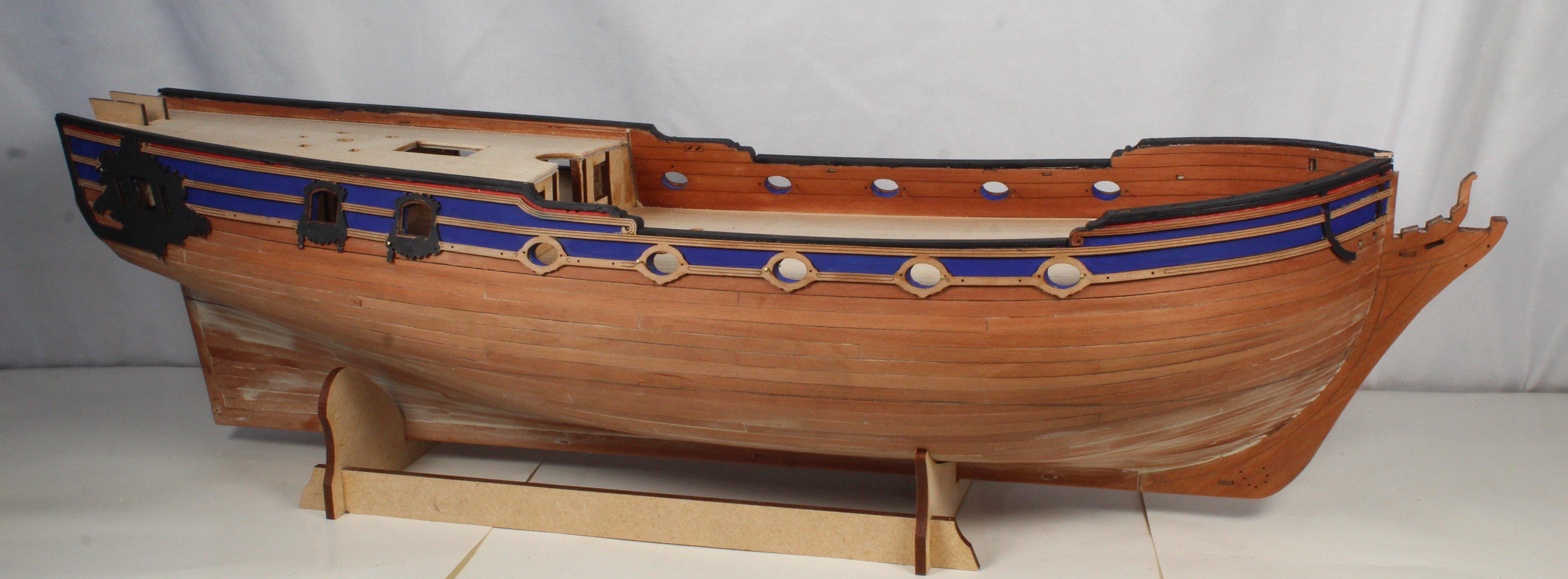
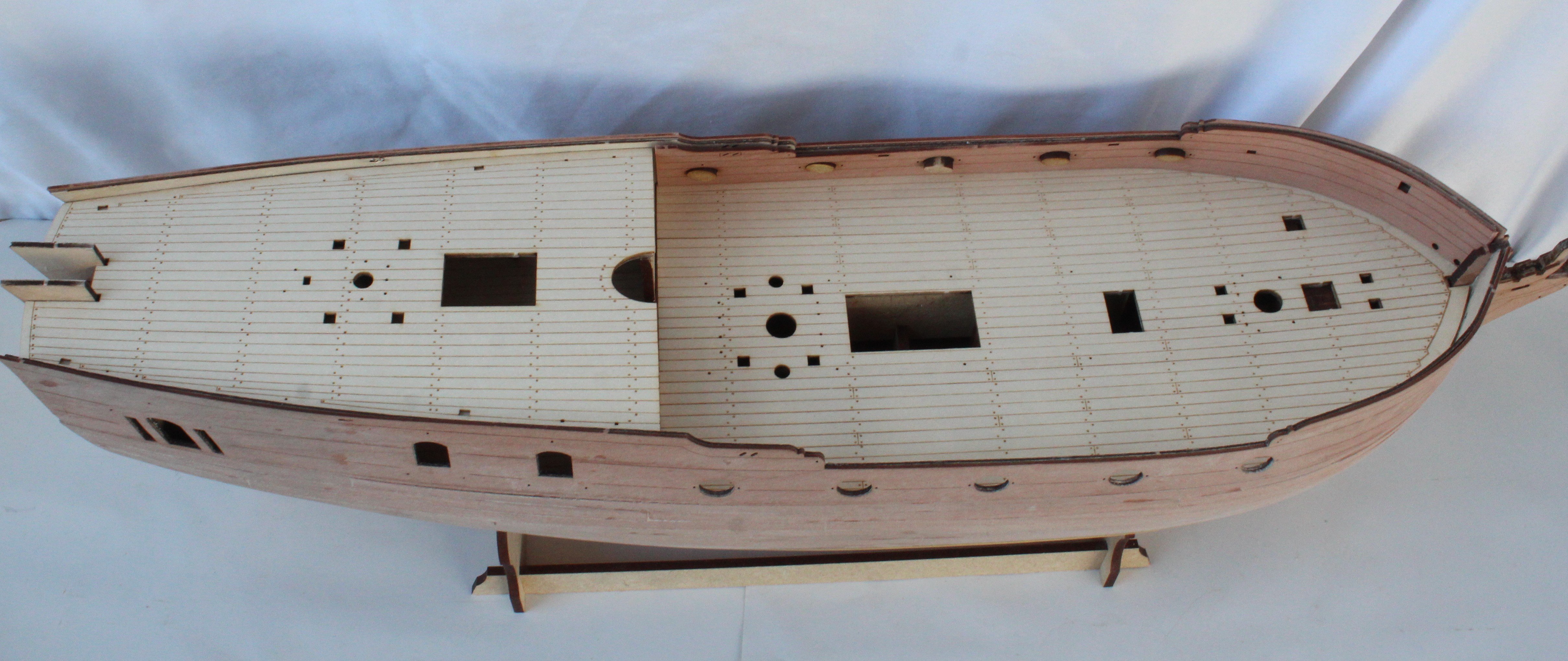
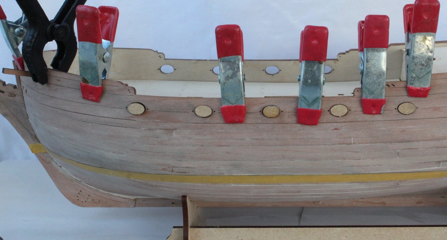
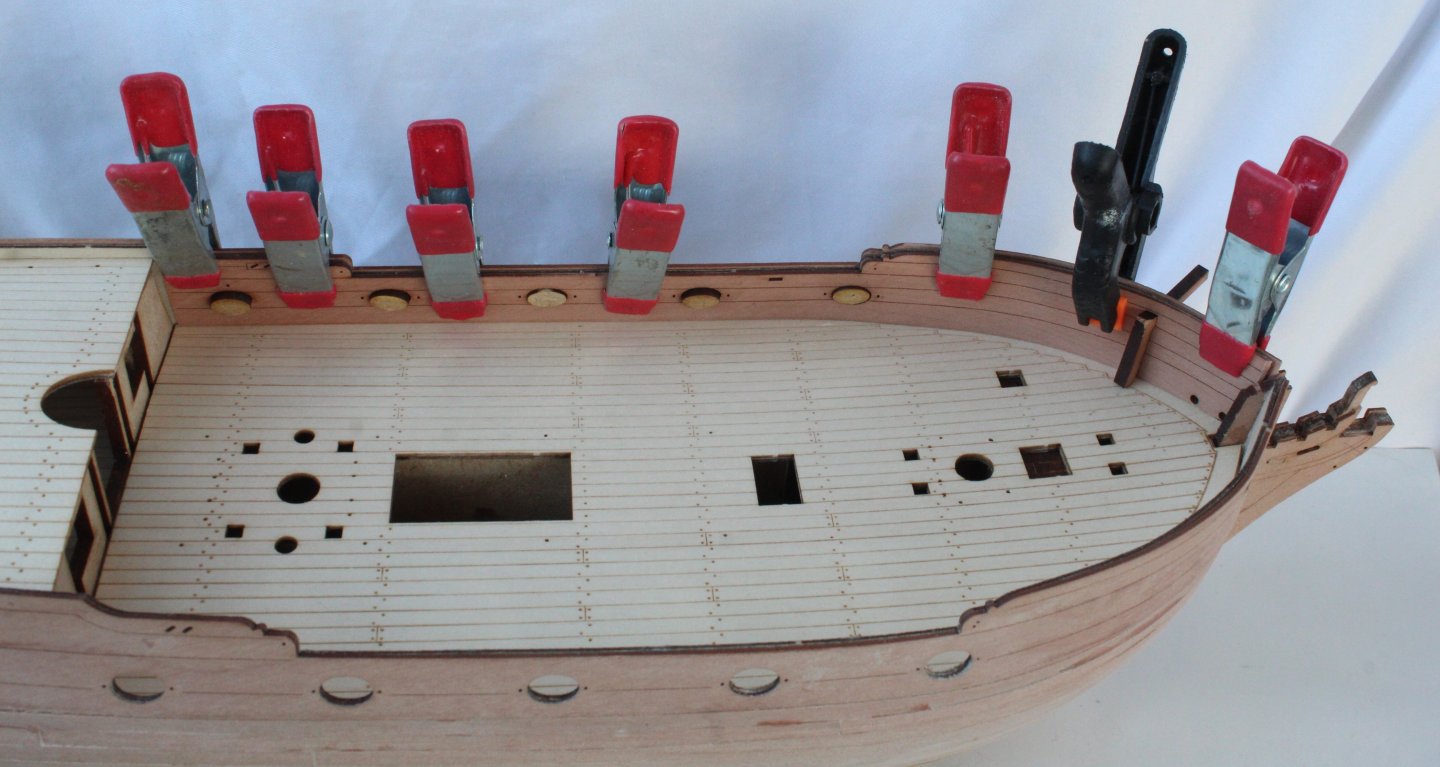
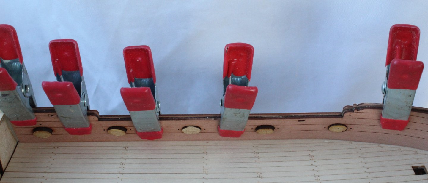
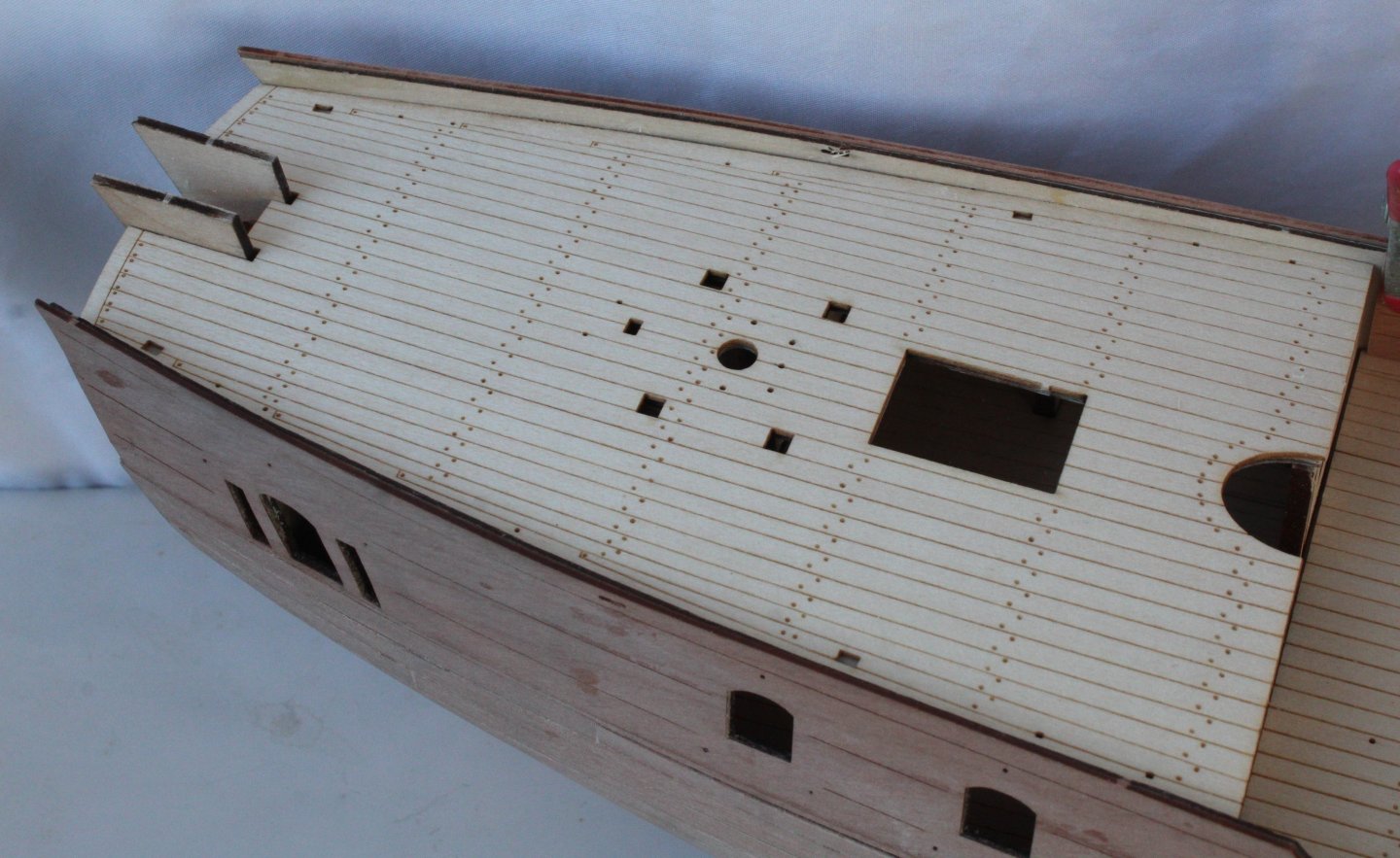
Build Log - Day 20 (28th - 30th Nov 2025) Task 40 – Completion of second planking I have now completed the second planking task. I am pleased with how the hull now looks, noting there will be a few areas to add some wood filler when it is time to paint the hull below the waterline. Photos Right-Hand Side Left-Hand Side Bow Stern


-
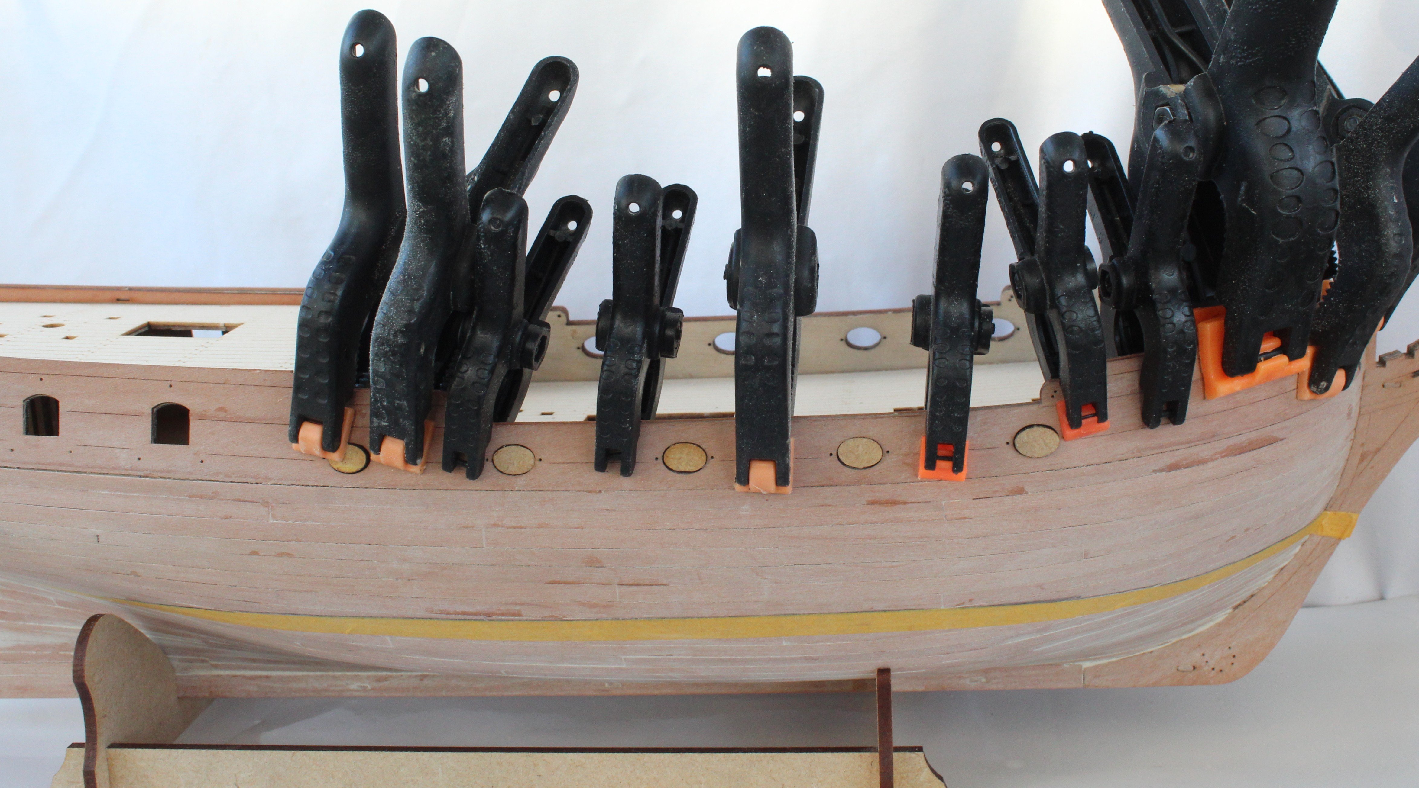
Build Log - Day 19 (26th – 27th Nov 2025) Task 39 – Start of second planking layer on left-hand side I am now working slowly and steadily with adding the second planking layer on the left-hand side. In the following photo I have completed the first banding section of 5 tapered planks around the bow. I am doing my best to match these planks up with the right-hand side. The next photo shows the first banding section around the stern After completing the first banding section I took some measurements and then added some tic marks for the remaining bow planks, as can be seen in the next photo. I used my digital callipers to help mark the positions. The next set of photos were taken after I had completed the second banding area. Now that I have completed the joint with the stern counter I will add some tic mark for the stern section for tapering.


-
Build Log - Day 18 (25th Nov 2025) Task 38 – Completion of second planking layer on right-hand side Following on from my last post in did not take me too long to complete the right-hand side second planking. My working method has evolved during this task. Using paper templates to get the right shape for the bow lateral band has certainly made a big positive difference. Also using a 4-butt shift pattern for the planking made the task much easier, especially with getting good joints with the stern counter and post. Although by no means perfect, I am pleased with how the planking looks and it is much better than any of my previous models. I am now debating whether to paint the section below the waterline white or to leave it with just a nice varnish. There is no need to decide just yet, and of course I will consult with my daughter-in-law before making a final decision. In the photos below I have brushed some water on the planking to give an impression of how it will look once varnished. It also highlights all the flaws. Photos The completed hull The stern area Midships, shows the 4-butt shift pattern Bow area


-
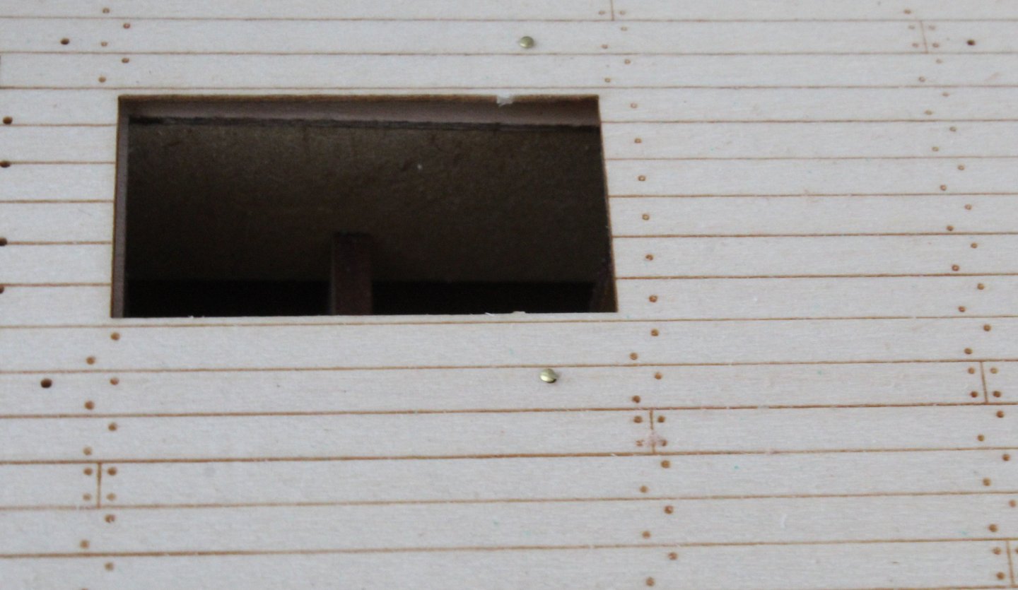
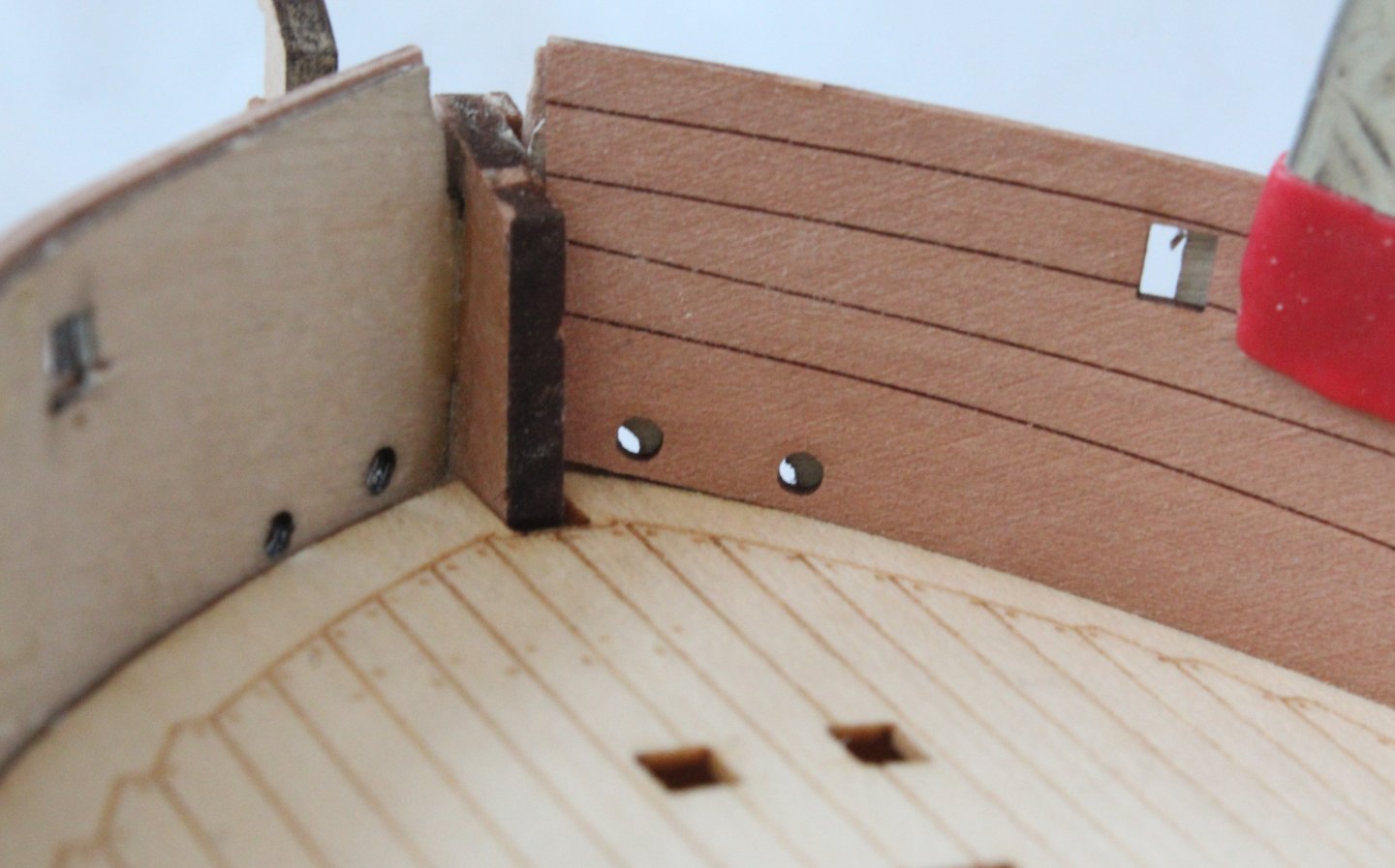
Build Log - Day 17 (23rd -24th Nov 2025) Task 37 – Plans to complete 2nd planking on right-hand side Work is progressing with adding the second planking to the right-hand side. I have now reached the stage where the final two / three runs are required. The following is a photo of the current build status. There is some glare reflection from the lights as I took these pictures in the evening with my LED spotlights. I have now started work on adding the next plank, and in the next photo I am using a spare piece of planking material to gauge the shaping of the final bow plank. The next photo shows the stern area, the pencil line shows where the final two planks will fit. There is a bit of damage to one of the stern planks, I am not sure what happened there. In the next photo I am checking that two full planks will fill the gap. However, when checking the midship section the gap is approximately 2.5 plank widths, which is a bit frustrating. In the next photo I am checking where the gap is back to 2 plank widths on the bow. My plan, to complete the planking is try and leave a rectangular 2mm shape for the final midship infill.


-
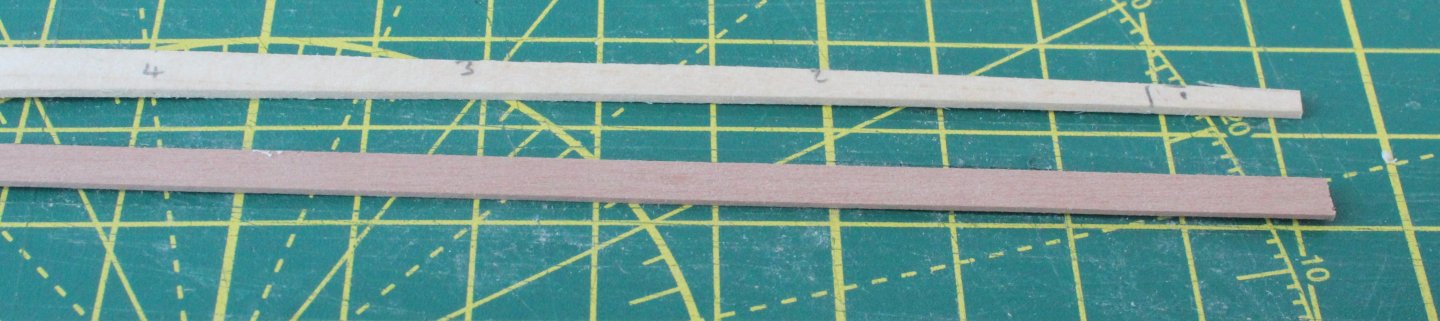
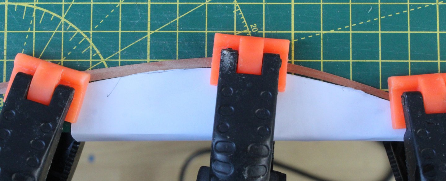
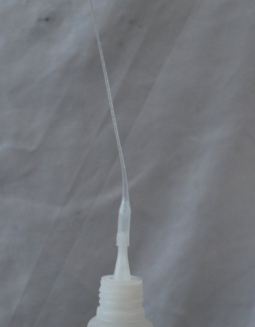
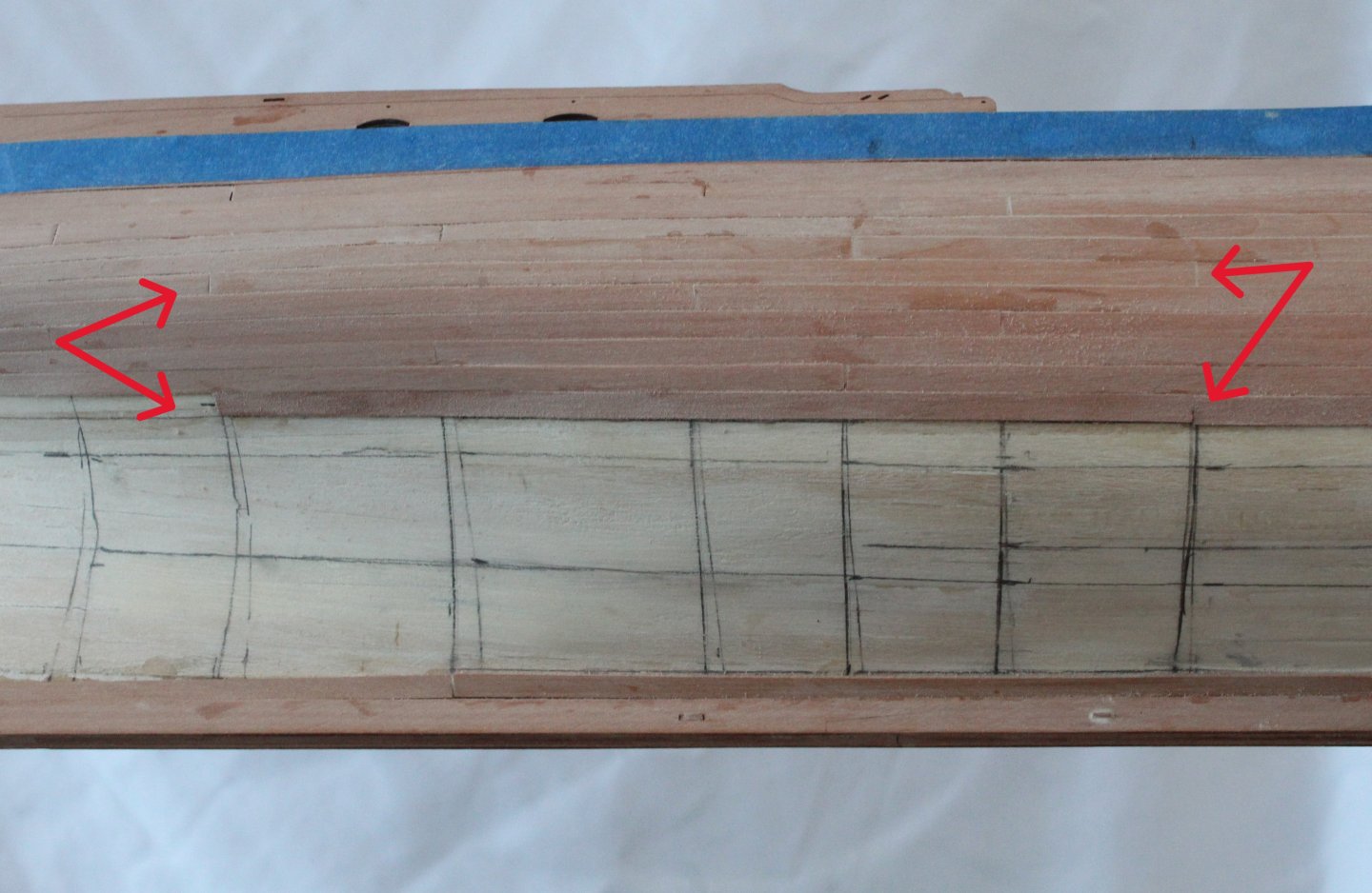
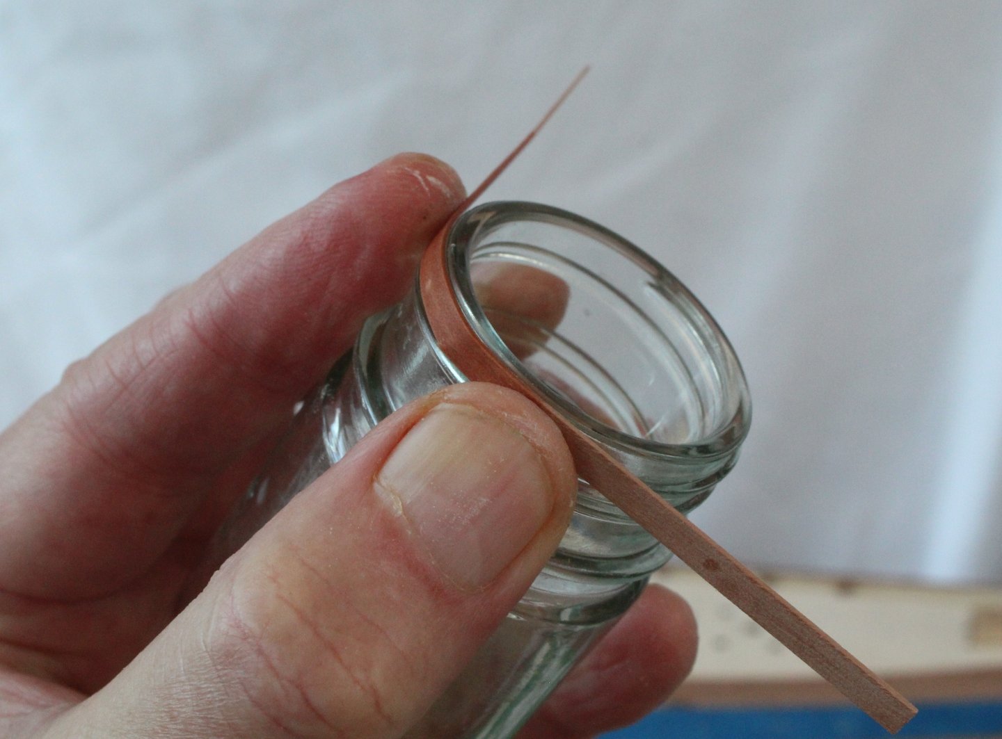
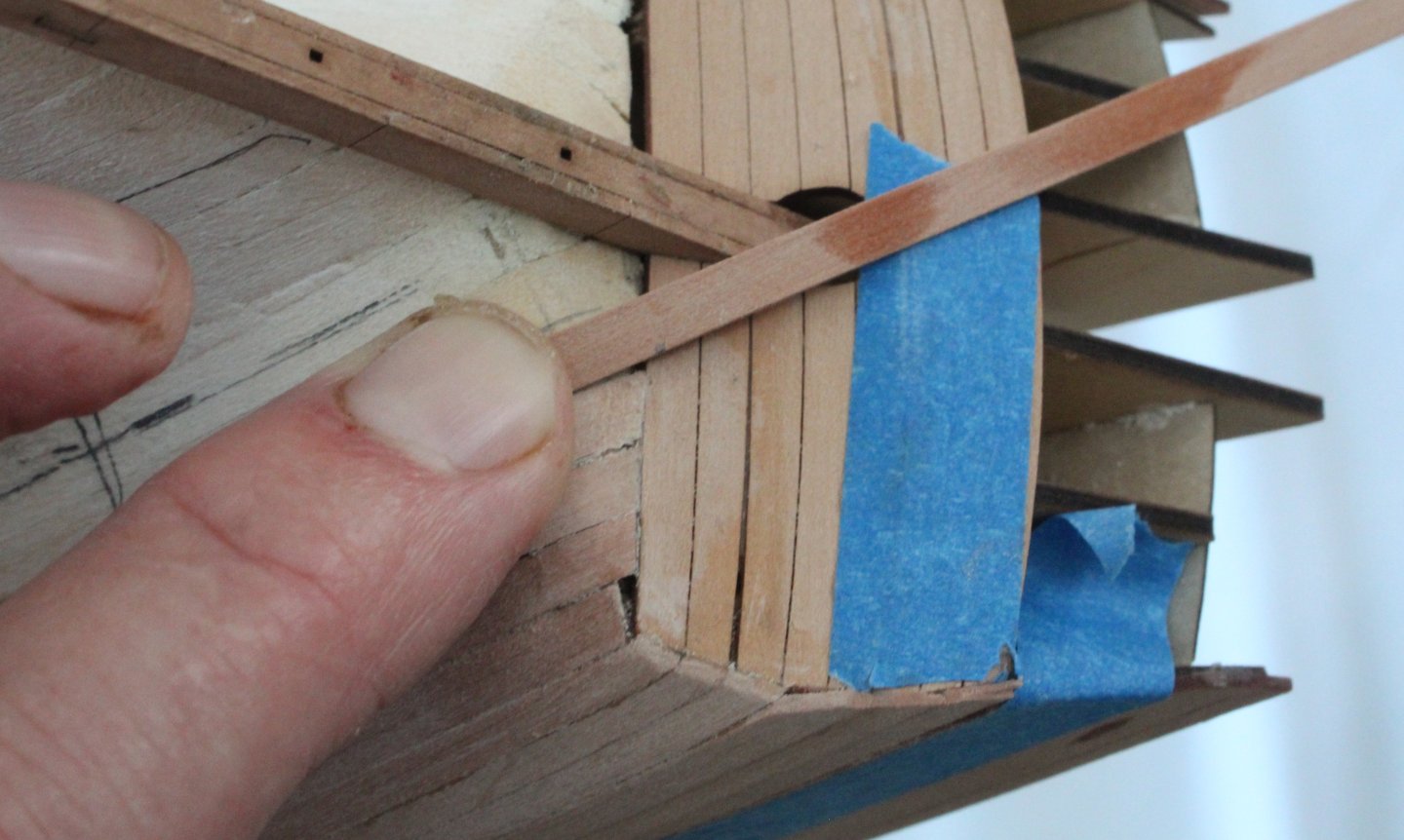
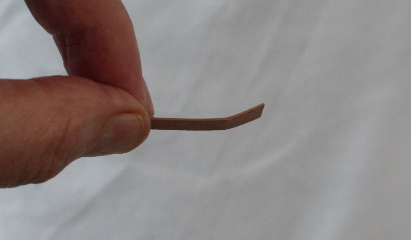
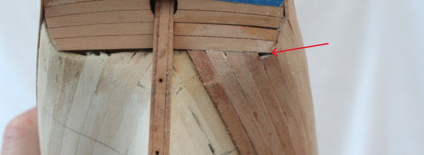
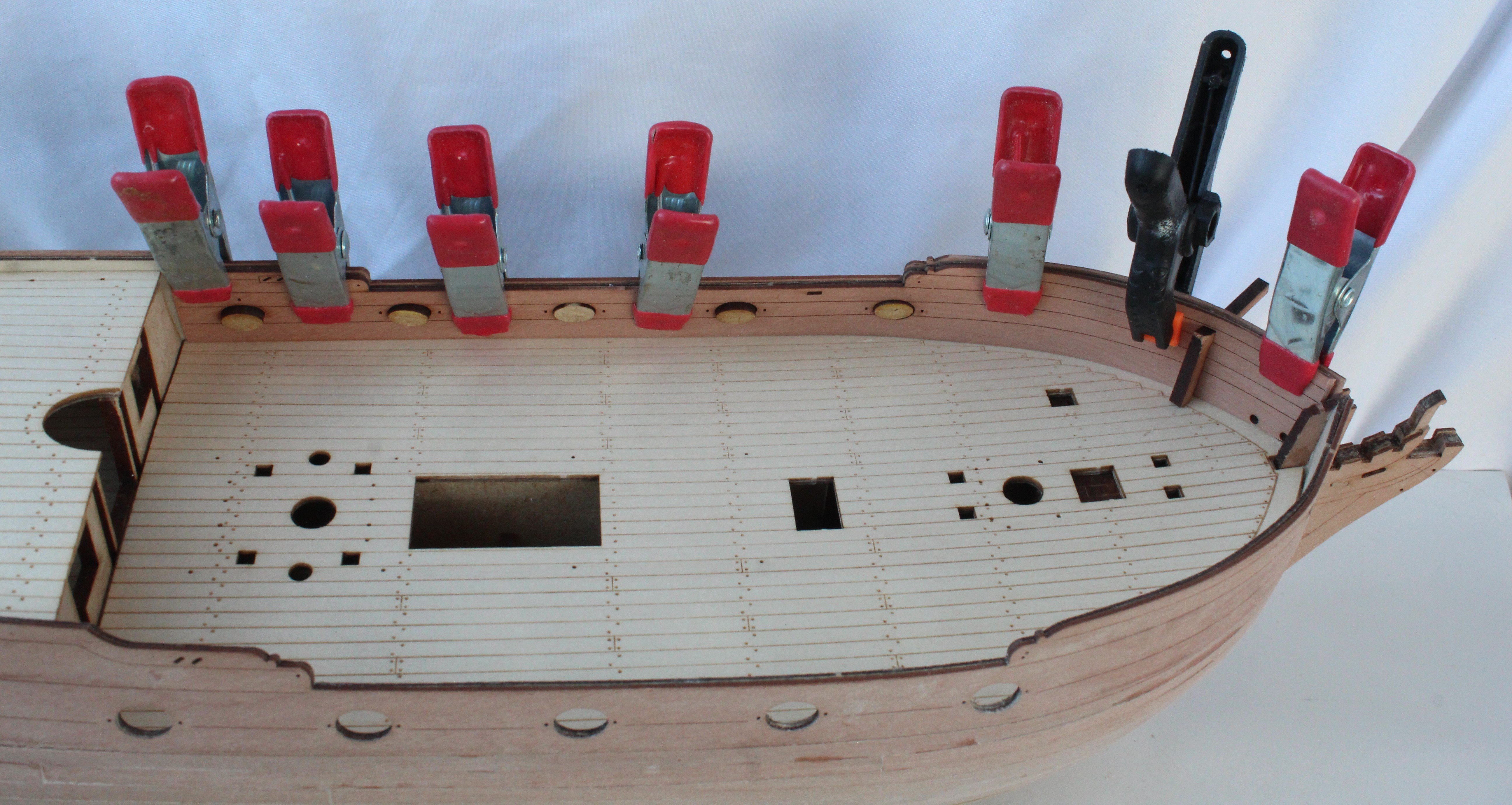
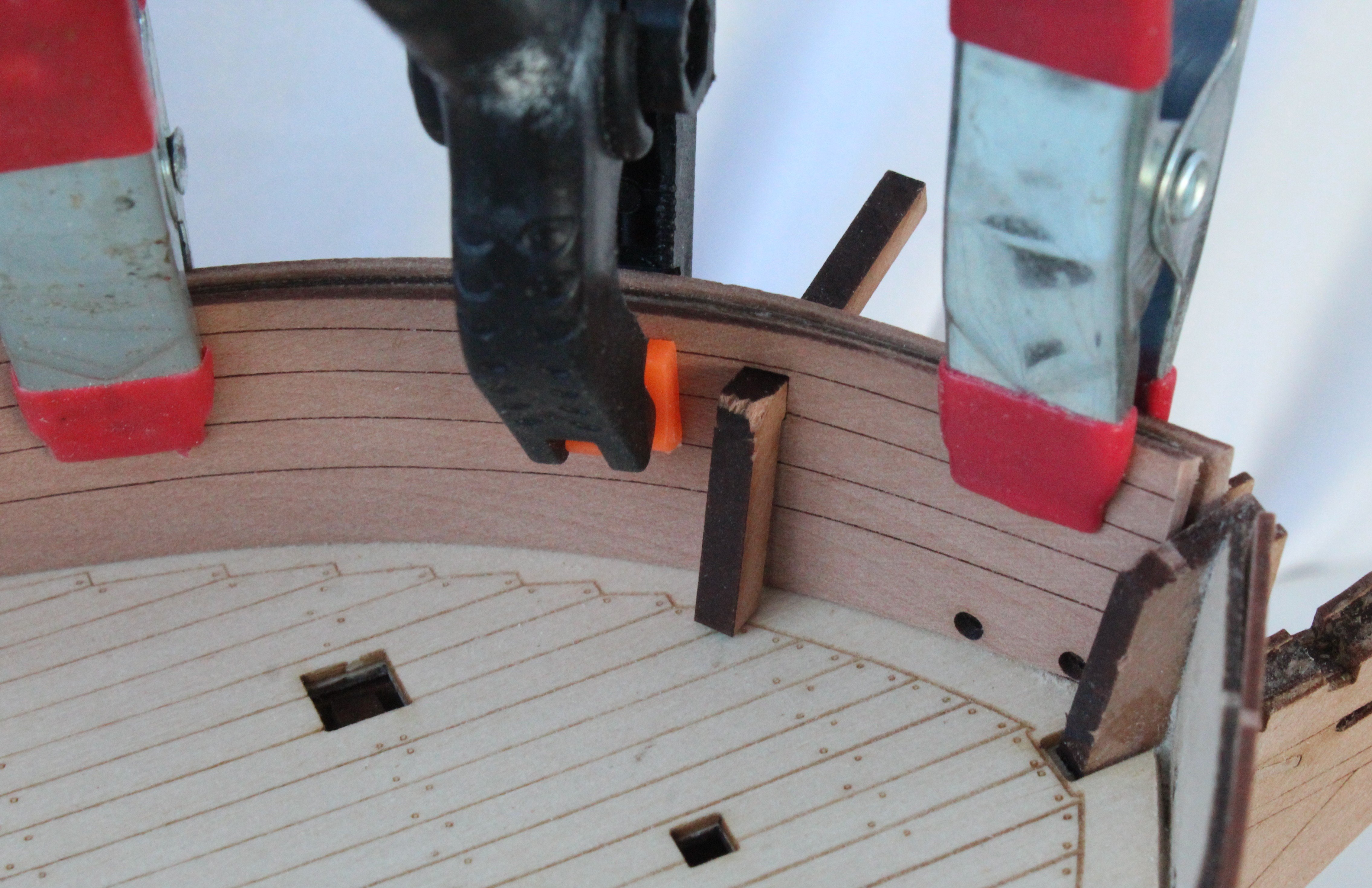
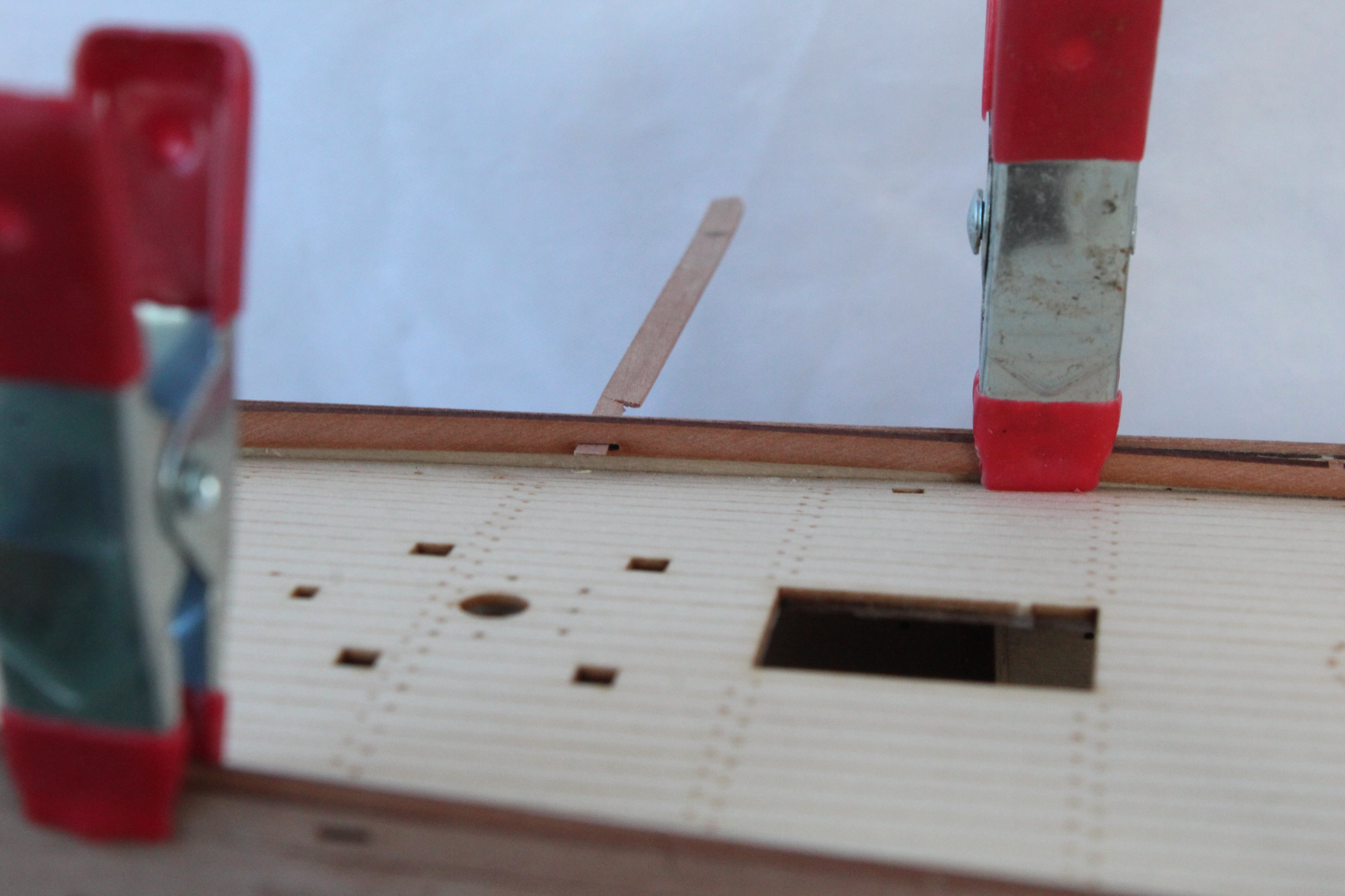
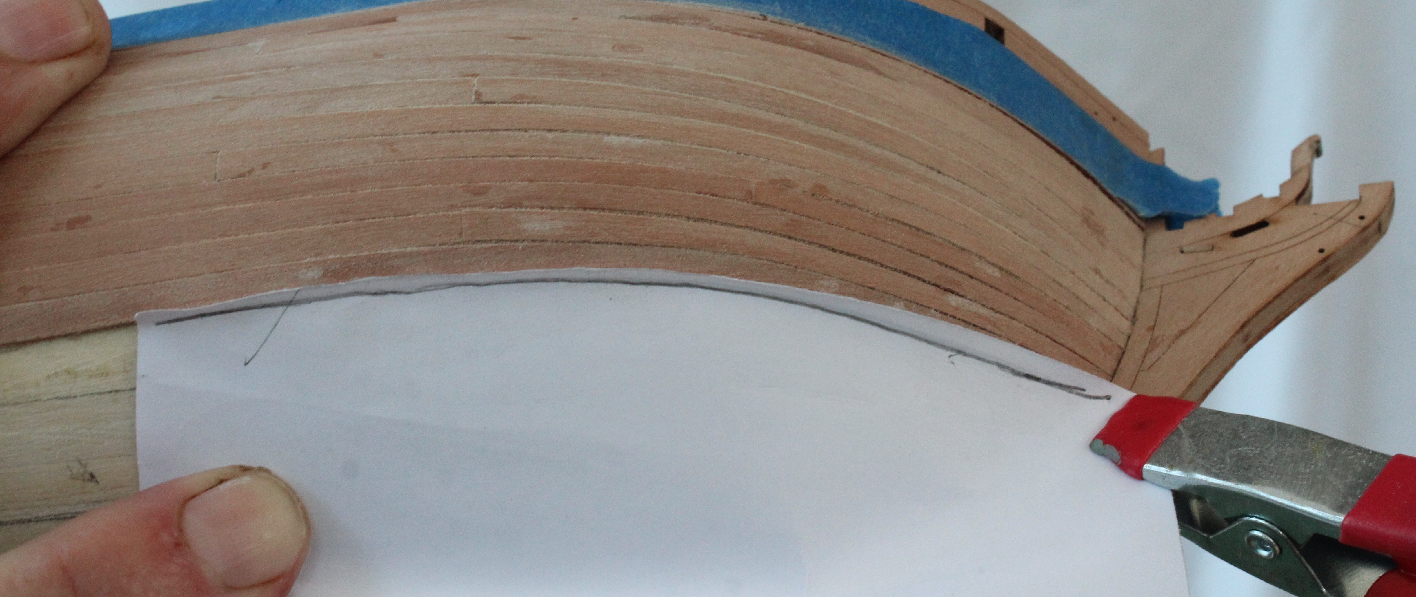
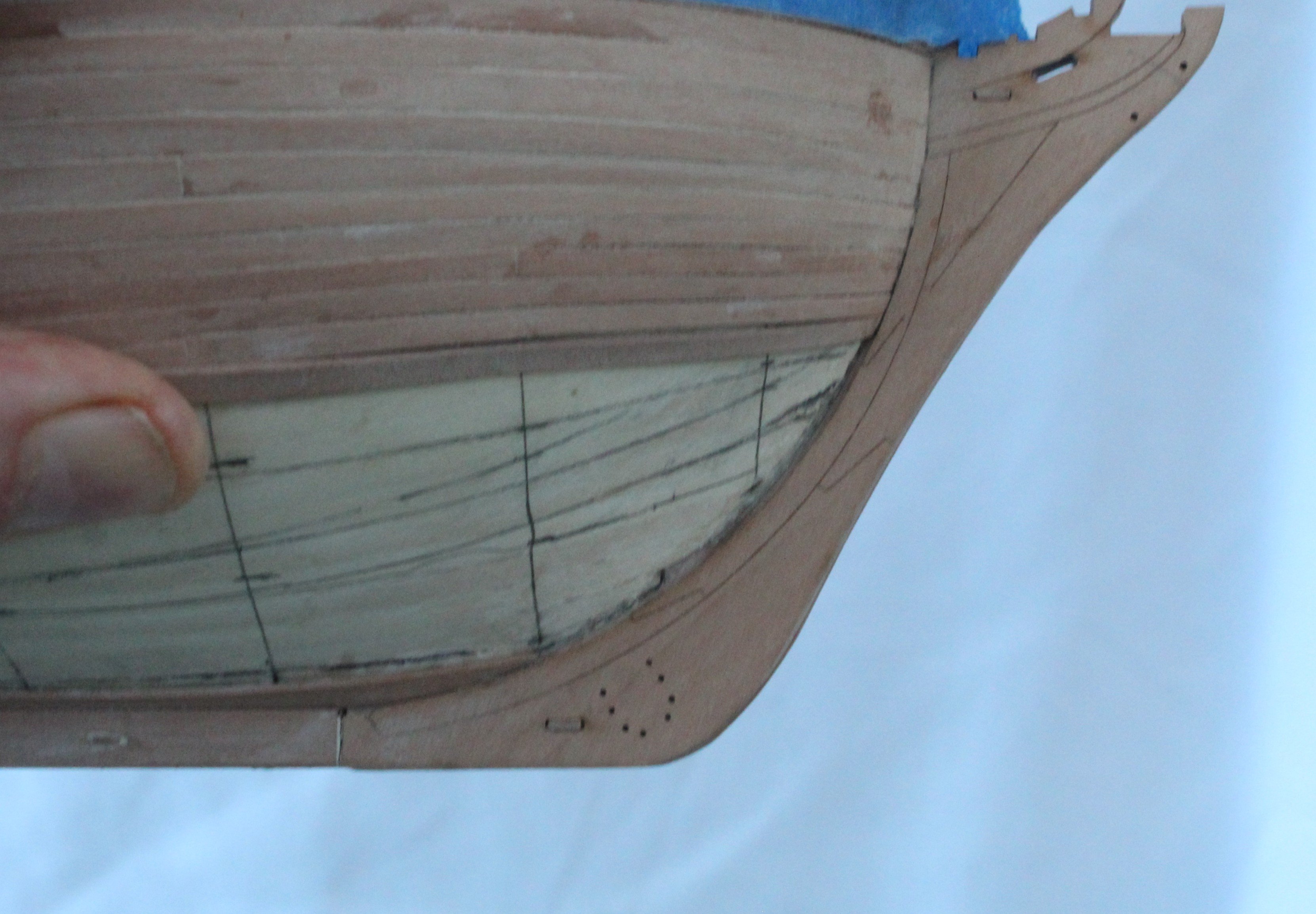
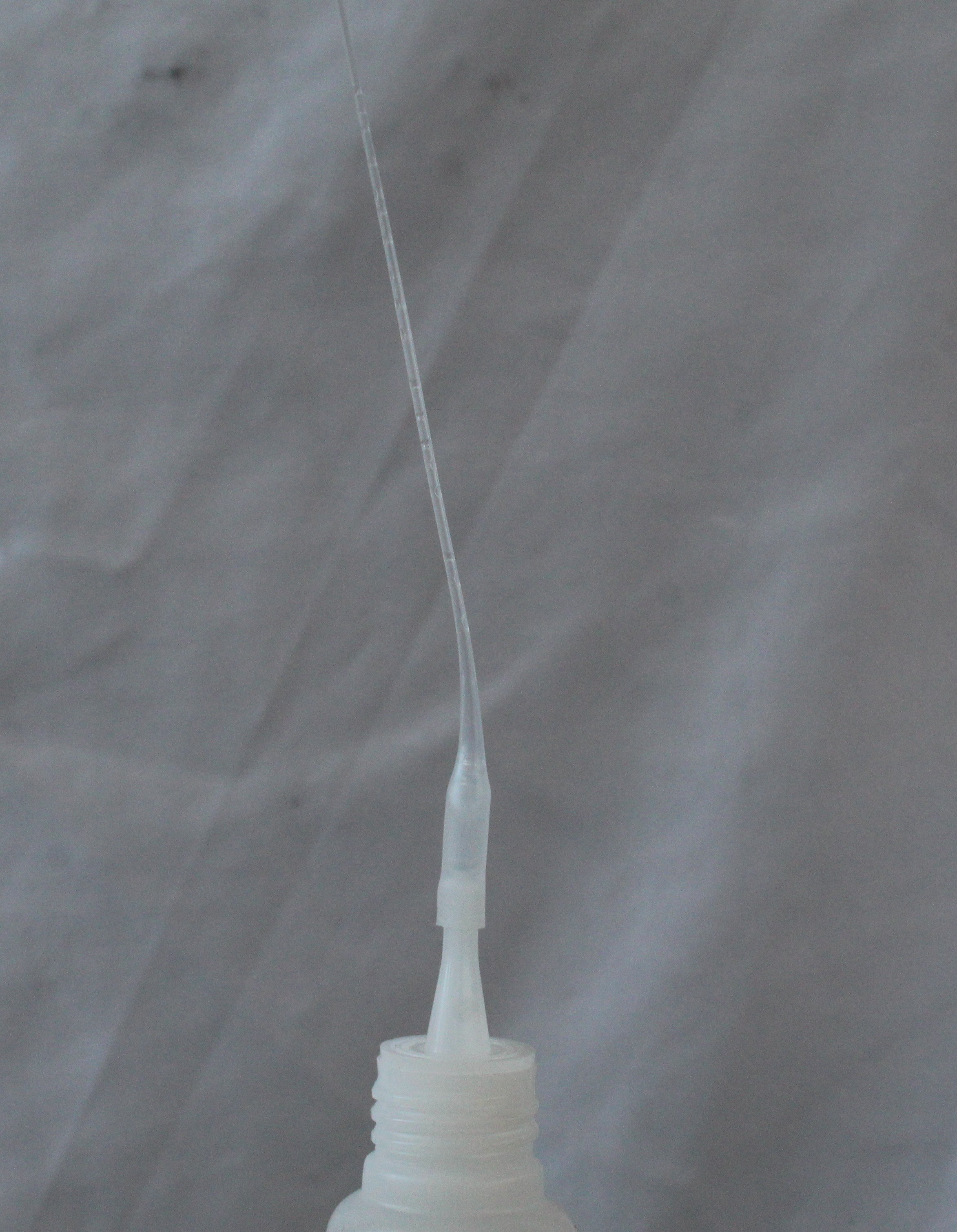
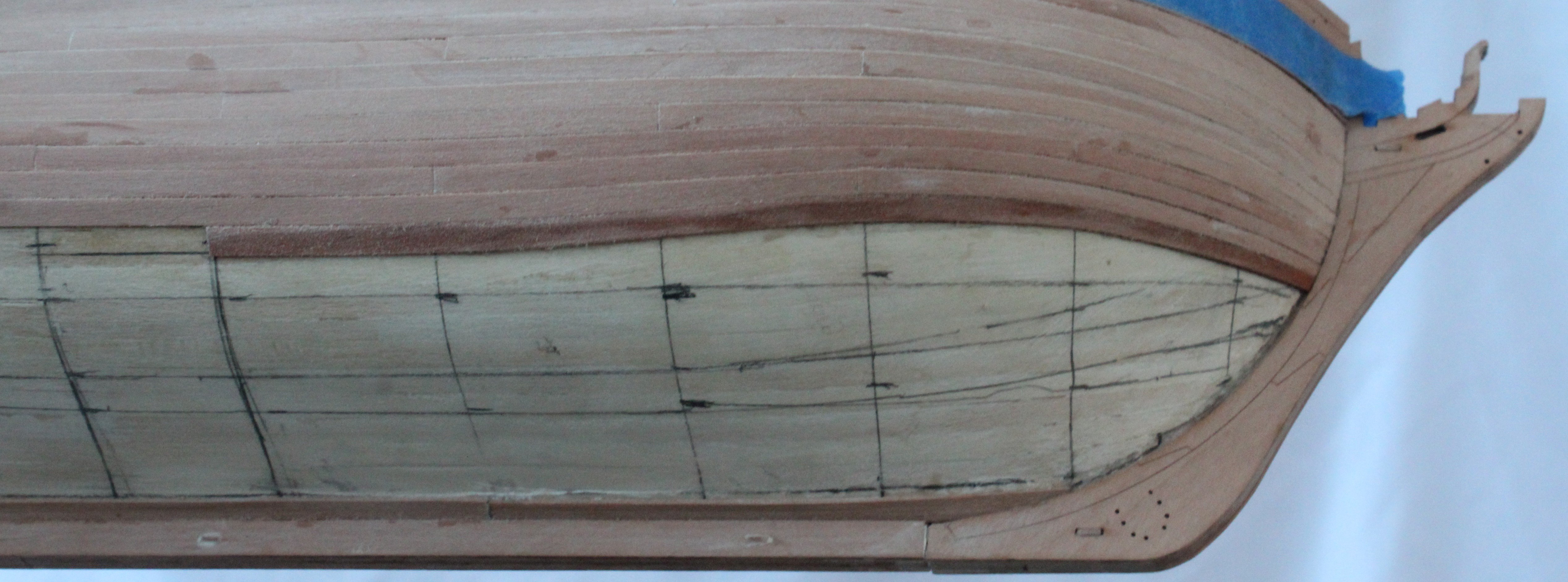
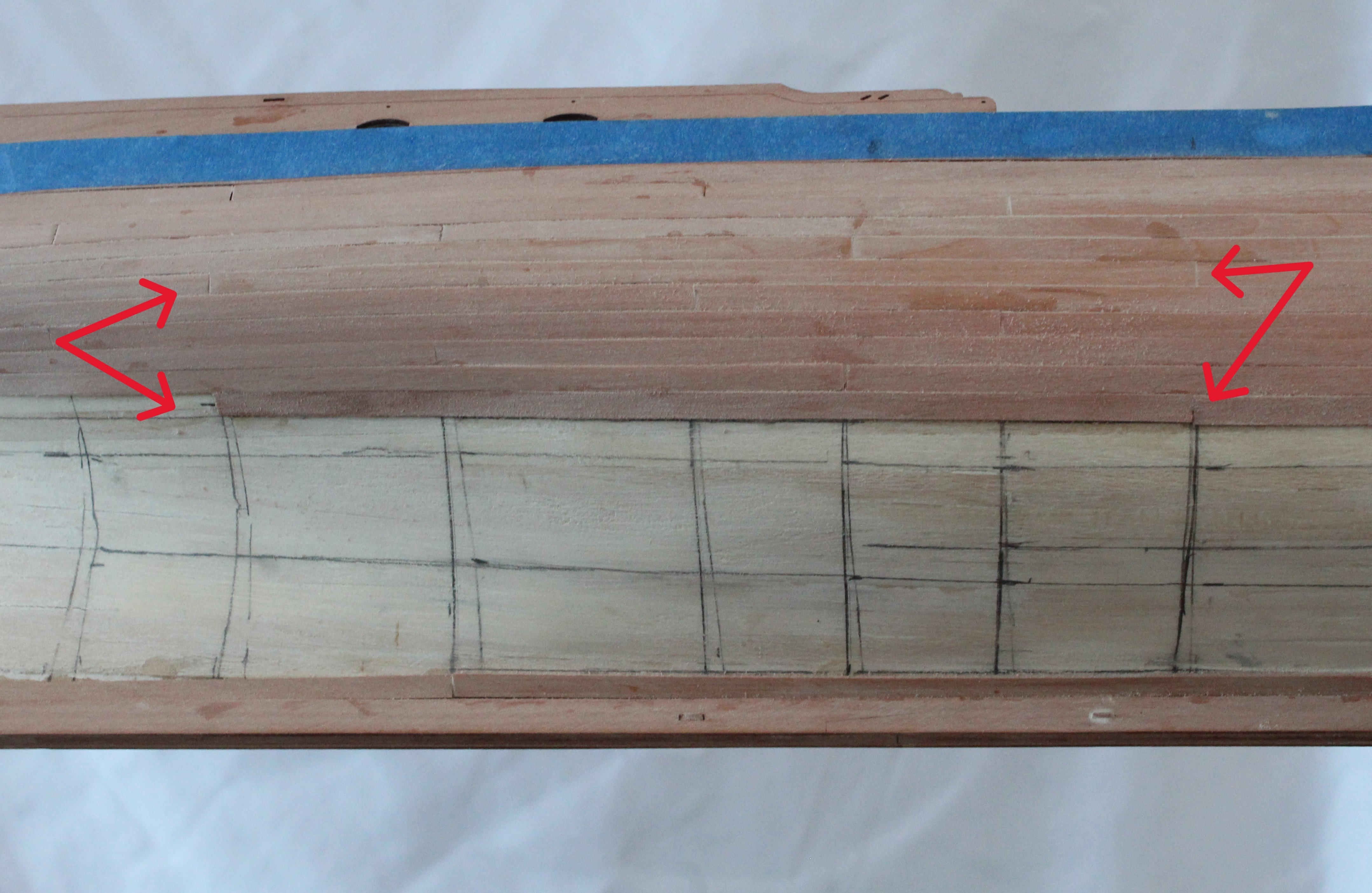
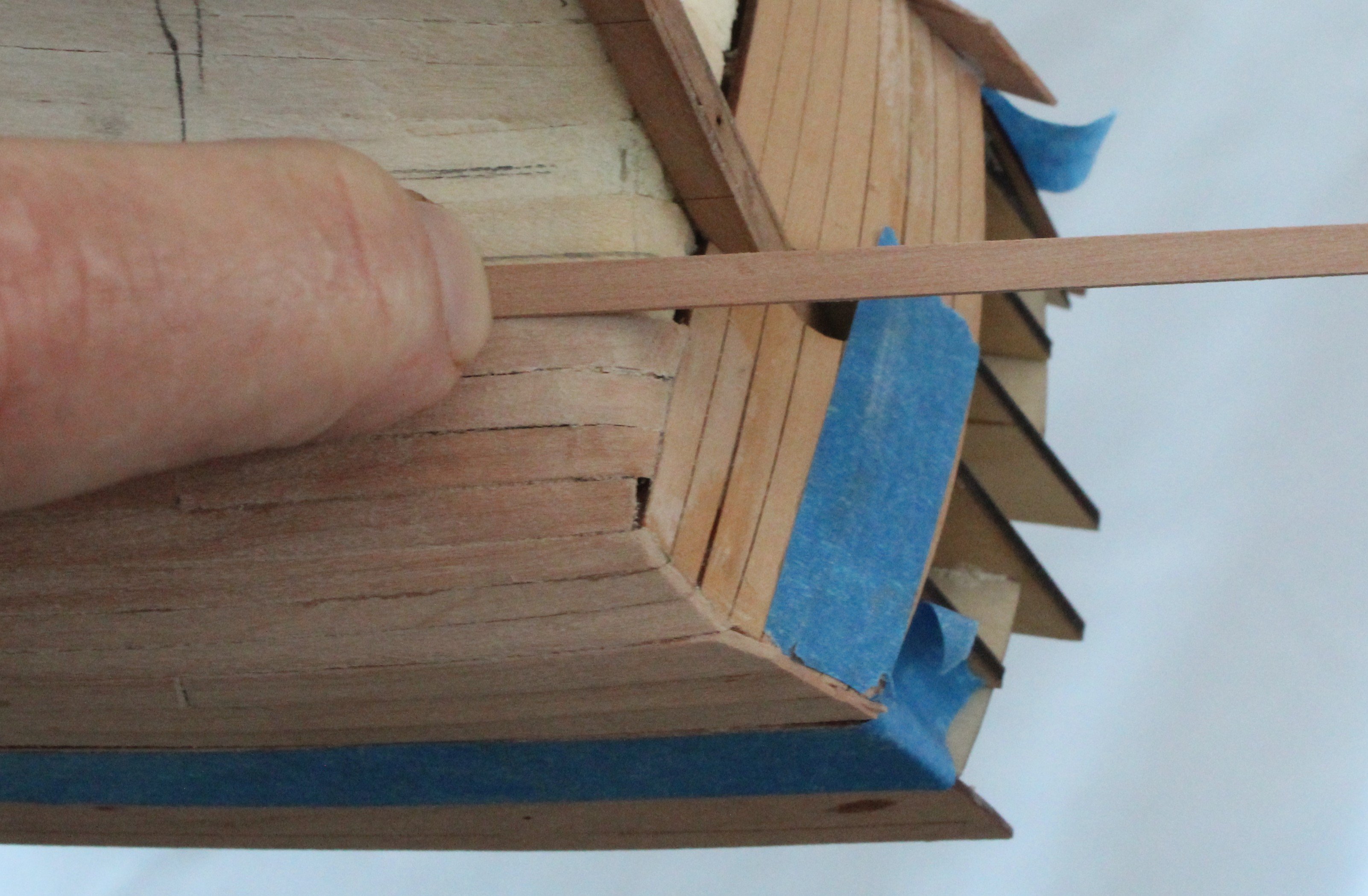
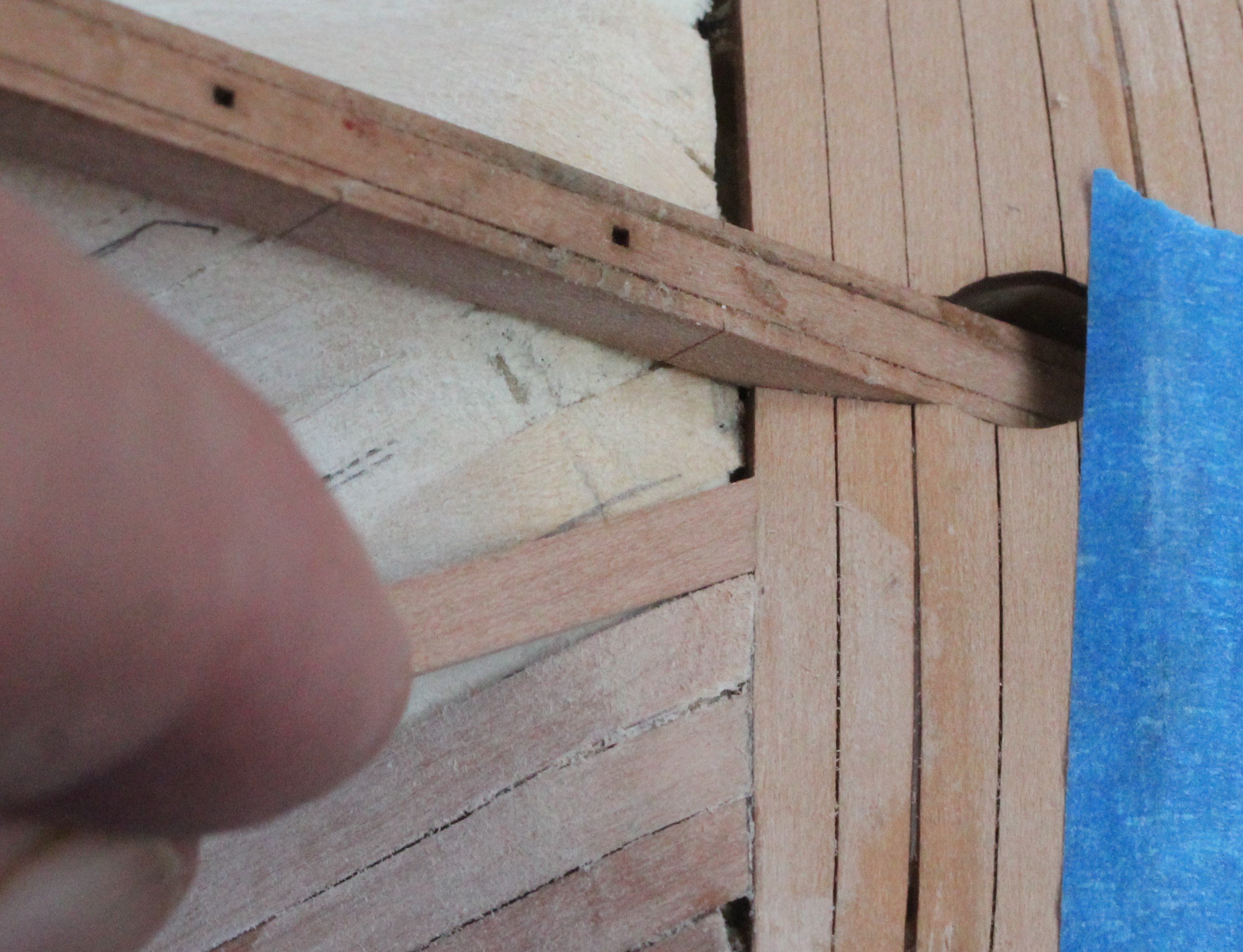
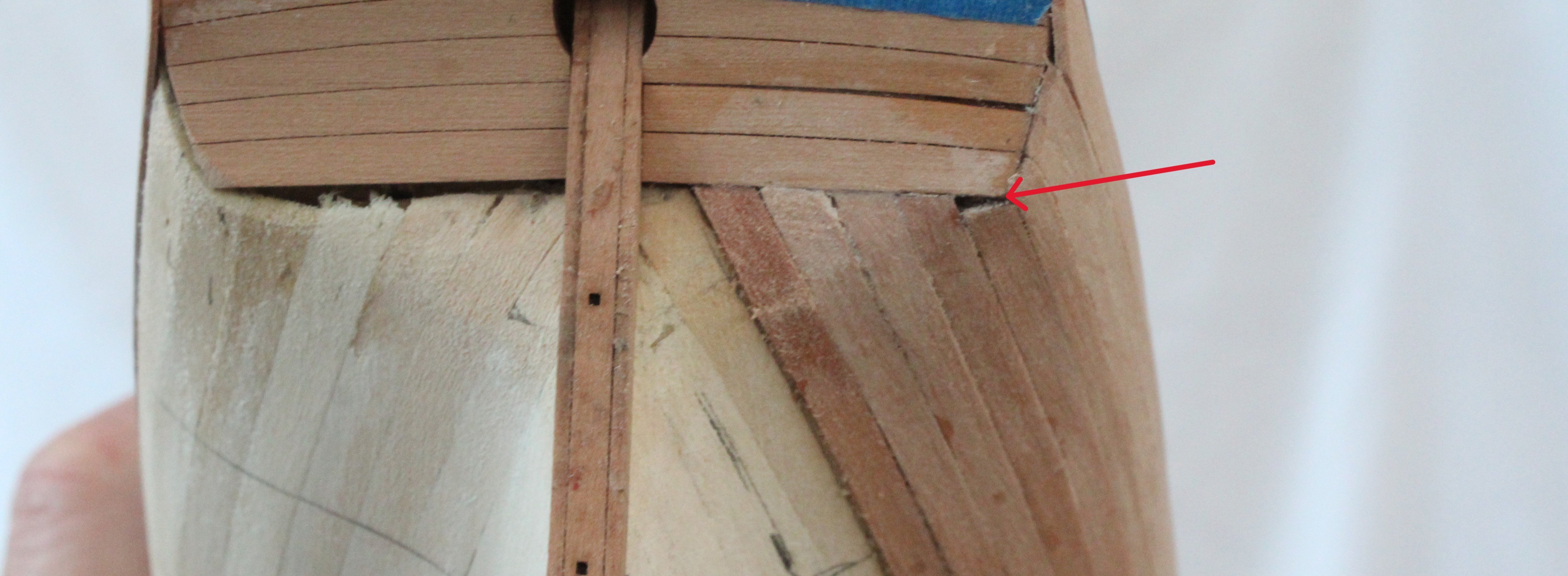
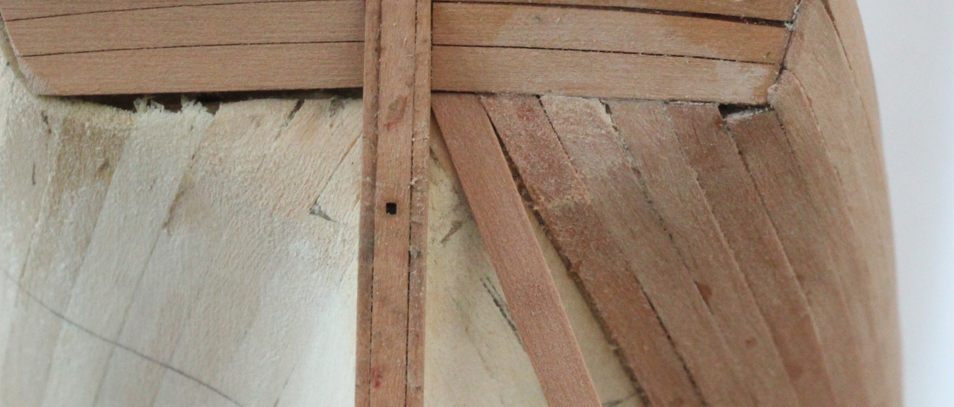
Build Log - Day 16 (20th – 22nd Nov 2025) Task 36 – Adding one planking layer I thought I would share, in detail, the method which I am now using to fit the second layer of planks. Step 1 – Creating a paper template for the lateral bend A piece of paper is folded underneath the plank. I then use a pencil to trace the required bend, as shown in the photo below. Next I cut along the pencil line and this becomes the template for the lateral bend. Step 2 – Tapering the plank Using the various bulkhead measurements taken when creating the banding areas, I use my digital callipers to mark the required widths. You will note, in the photo below, I also have a guide plank to indicate the positions of the various bulkheads. Step 3 – Lateral bend of the plank Once the taper has been applied the plank is then laterally bent. The paper template is used to set the required curve, as shown in the next photo. Water is brushed on to the plank and a hair dryer is used to apply the heat. Step 4 – Test Fit Once the plank has been bent as per the template it is test fitted. As can be seen in the next photo the plank sits flush with the previous plank without any force added. The plank is then cut to the required length as per the 4-butt shift pattern. Step 5 – Gluing the plank Glue is applied to the hull, using the following attachment to the super glue container. This attachment has proved to be an invaluable asset in this respect. I brush some water on the underside of the plank to aid the adhesive with the ca glue. The plank is then carefully fitted, working from the stem post. I am happy with how this plank (still damp) looks, once glued in place. Step 6 – Midships Plank The midships plank is cut to size, a slight bevel is applied to the top edge. Glue is then added to the hull before the damped plank is fitted. The red arrows shows the 4-butt shift joints. Step 7 – Stern Post Plank This is the plank that takes the most effort to fit. With the plank in position, as shown below, the underside is marked where the sharp bend to the lower stern counter pattern starts. The bend area is then wetted and a bend applied. I usually start with a gentle manipulation with my hand to get the start of the bend. Next I use a bottle to complete the task. A hairdryer is used when the plank is being bent around the bottle. The bent plank fit is then checked, as shown below. The bend looks OK. The pencil dot is where the plank need to terminate with the stern counter. Using the pencil mark on the plank I use the following template to cut the correct angle. The next photo shows the stern post plank prior to fitting. The dampened plank is then glued in position. This time I work from the stern post to the midships to ensure I get a good join with the stern counter. Apart from one plank (red arrow), where I worked from midships to stern counter when the plank was fitted, I am really pleased with how the joints with the stern counter looks. As can be seen in the final photo of this post the remaining stern counter gap to fill is exactly one full planks width which is ideal.