HOLIDAY DONATION DRIVE - SUPPORT MSW - DO YOUR PART TO KEEP THIS GREAT FORUM GOING! (89 donations so far out of 49,000 members - C'mon guys!)
×


Glenn-UK
-
Posts
3,162 -
Joined
-
Last visited
Content Type
Profiles
Forums
Gallery
Events
Everything posted by Glenn-UK
-
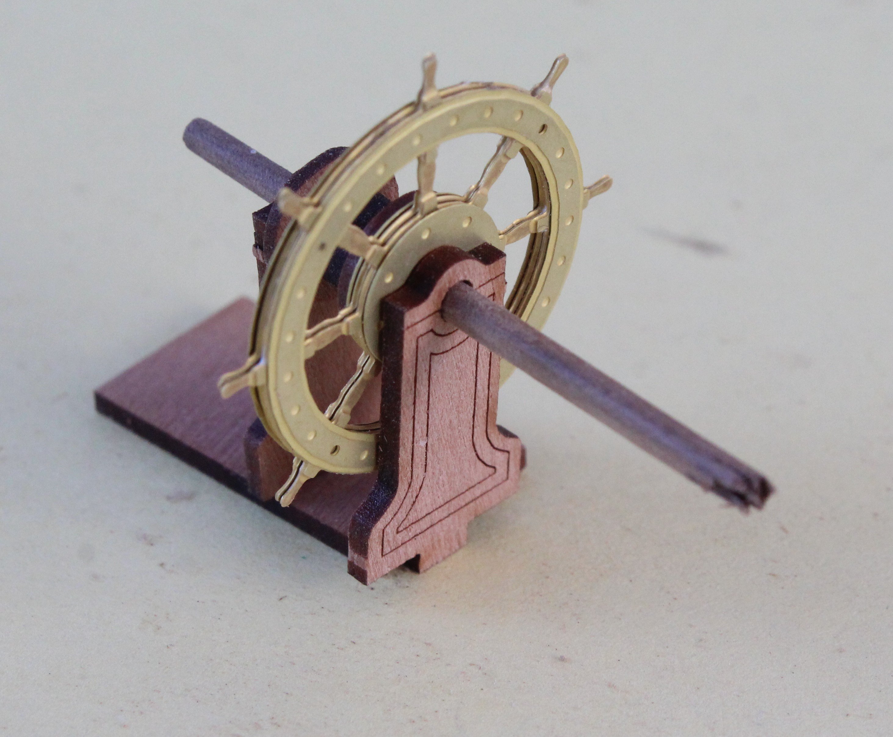
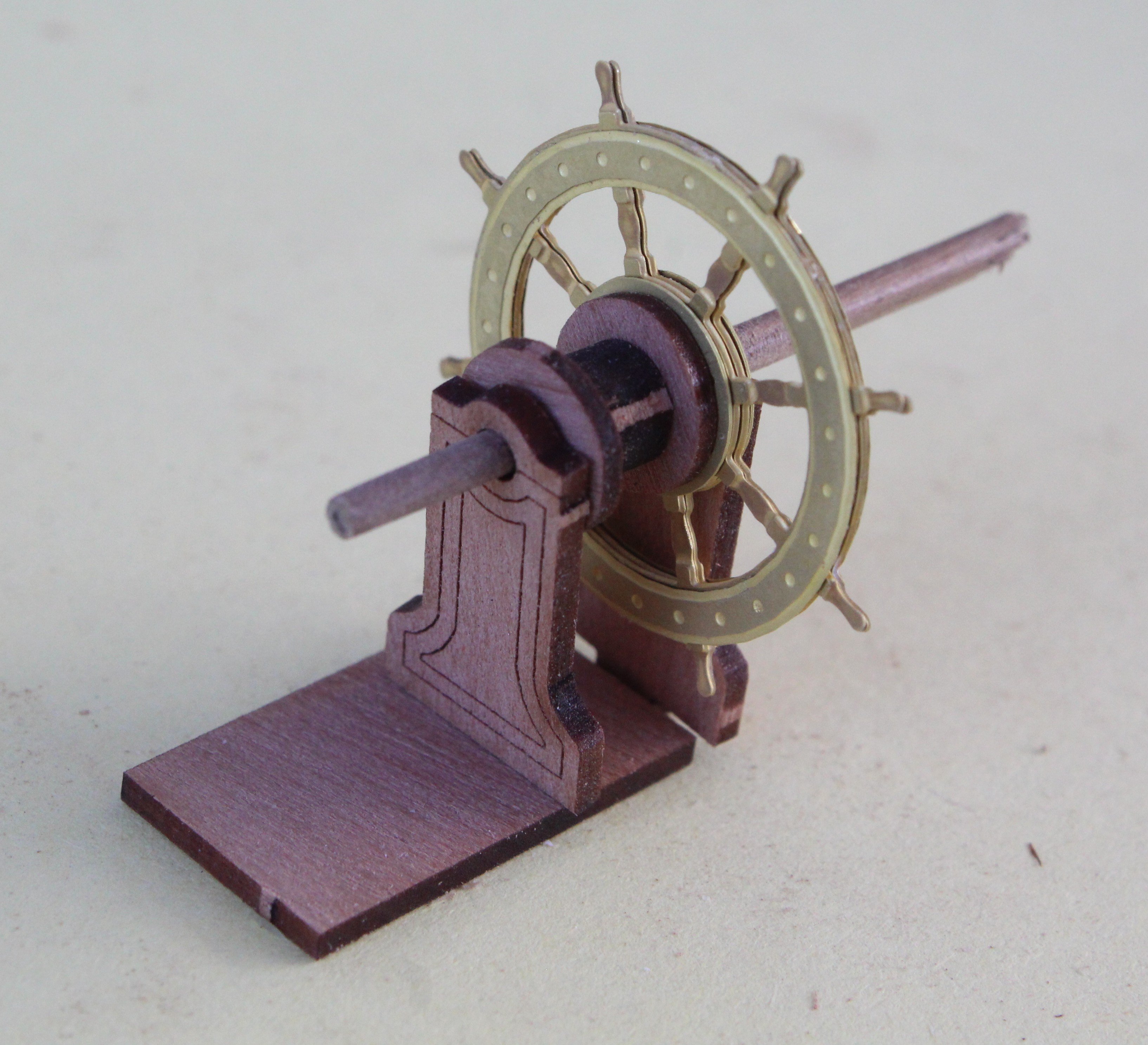
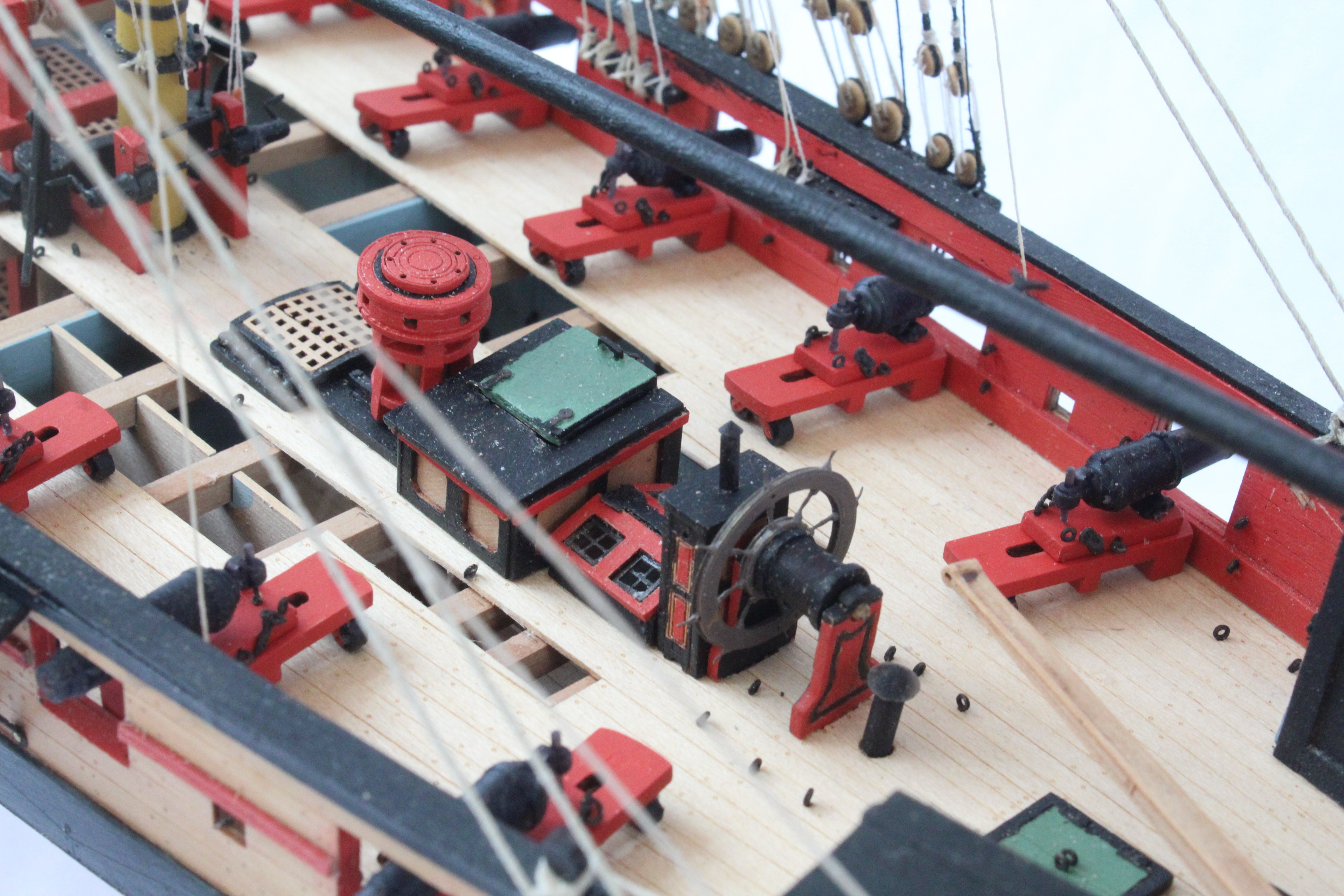
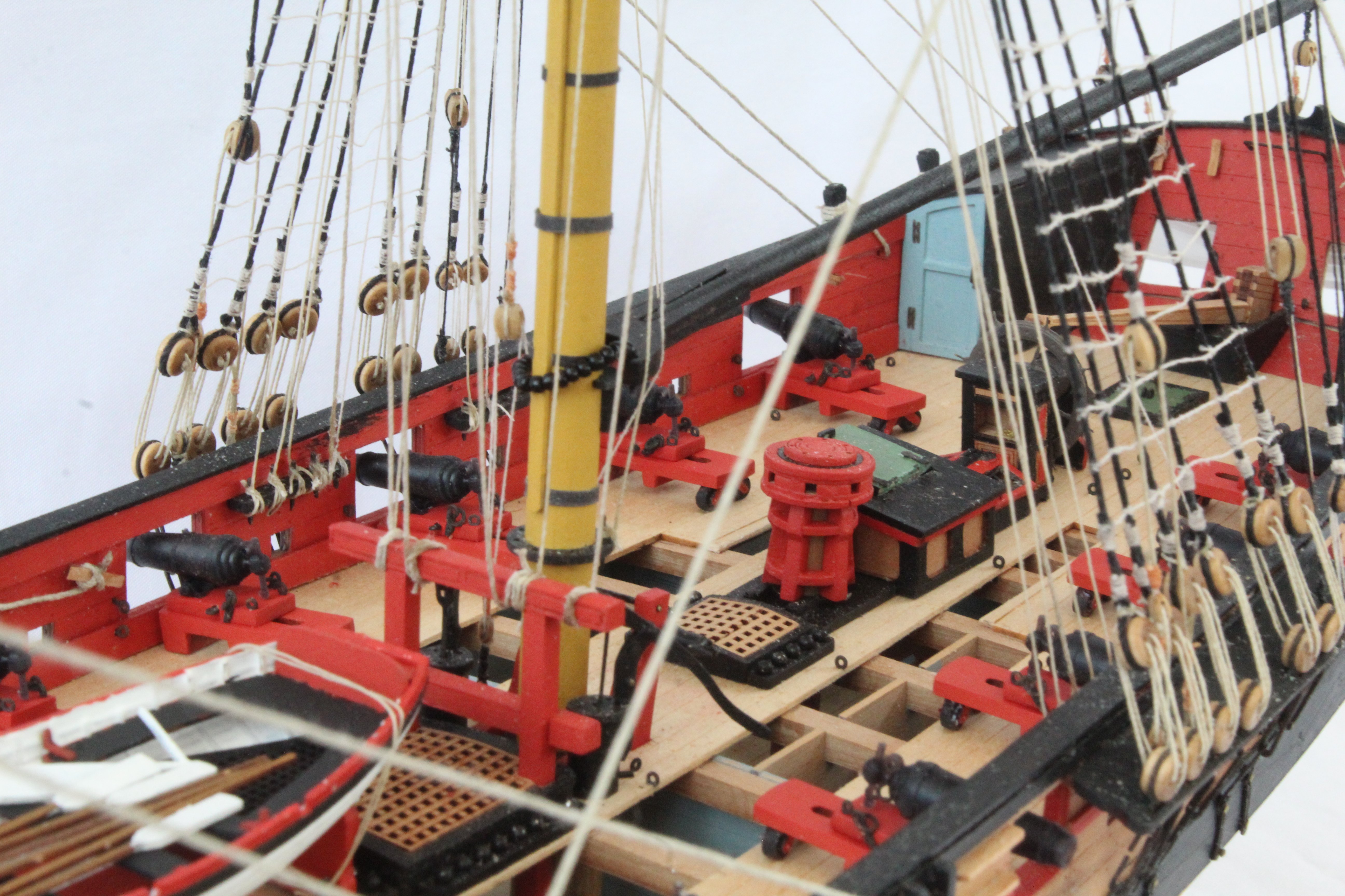
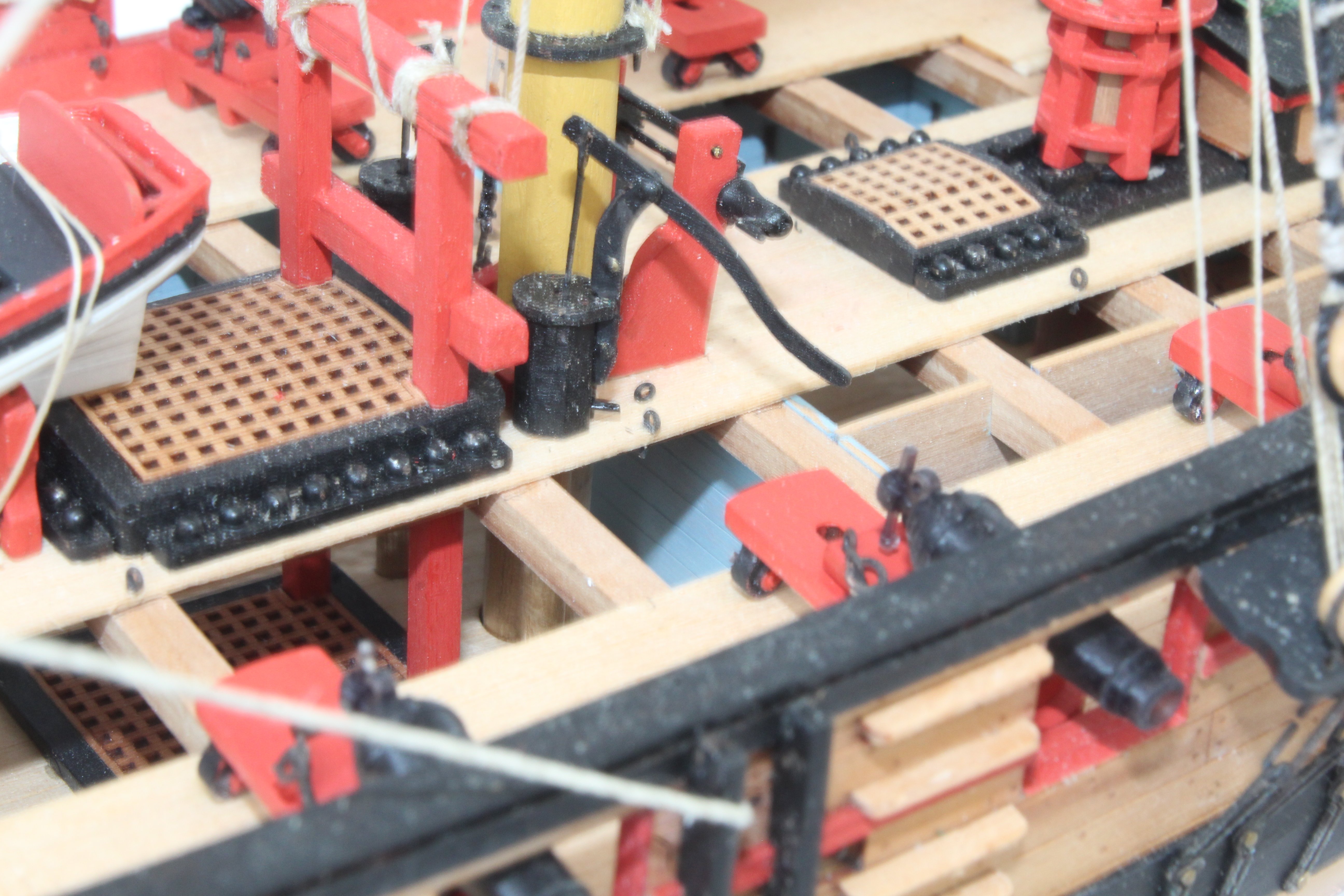
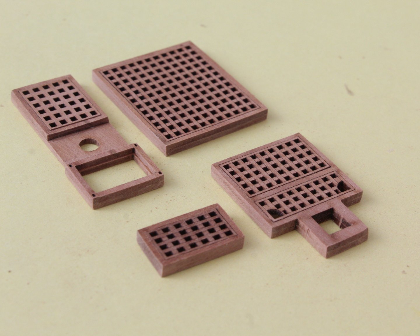
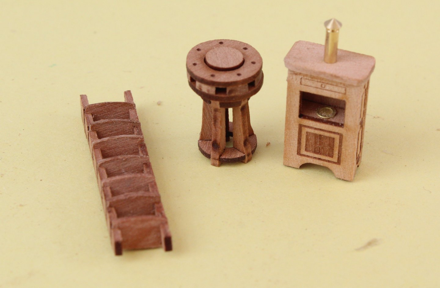
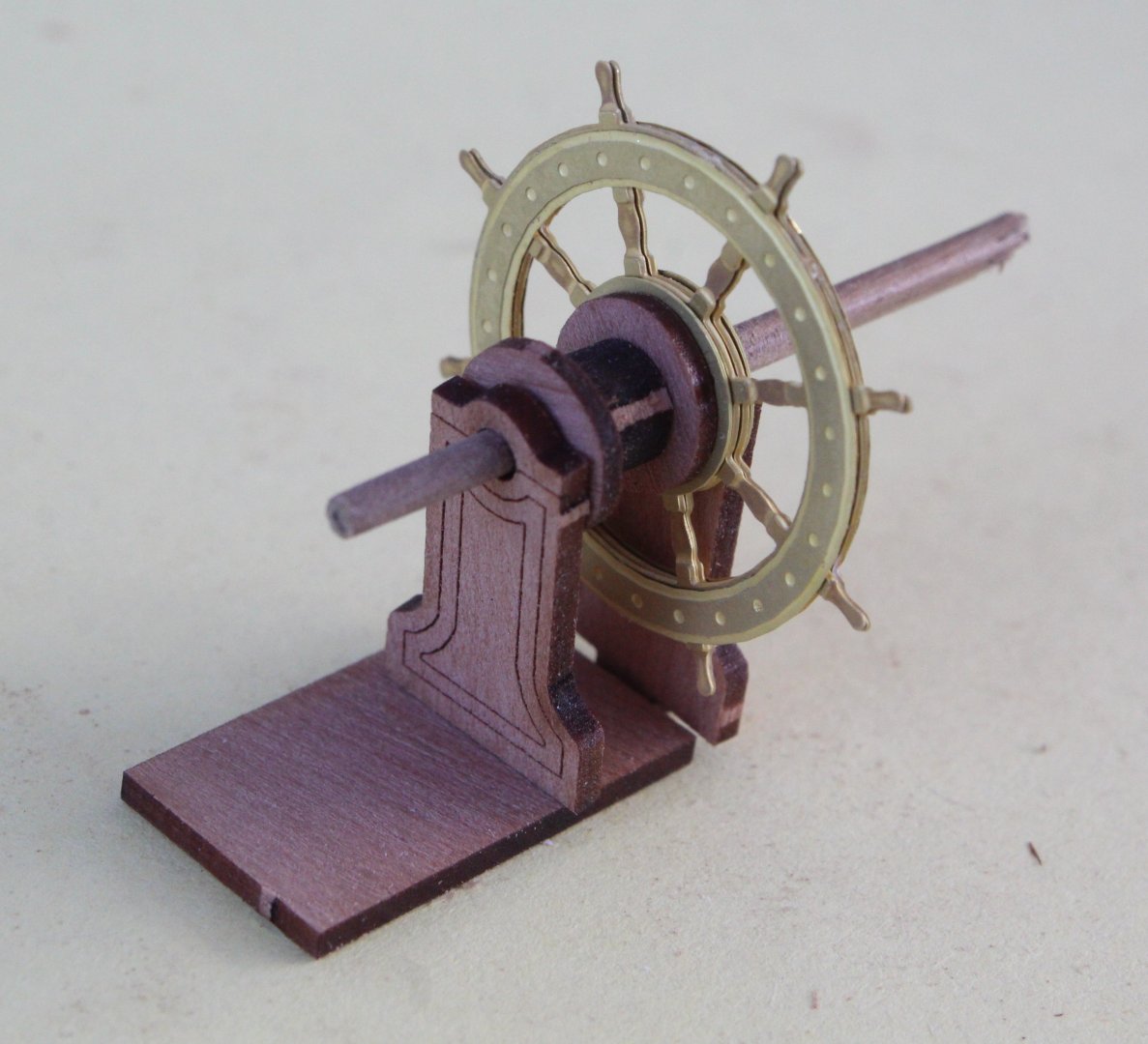
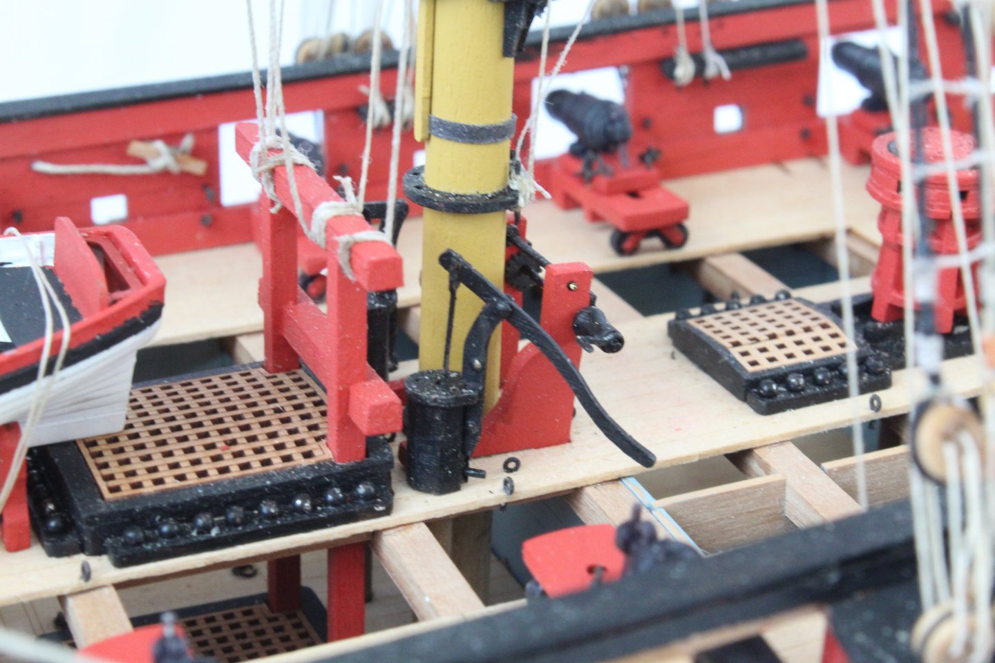
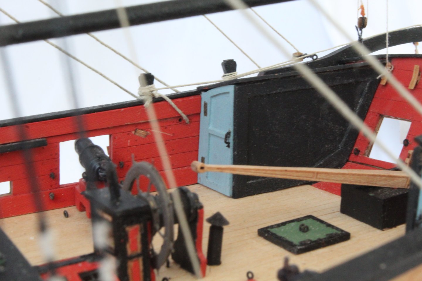
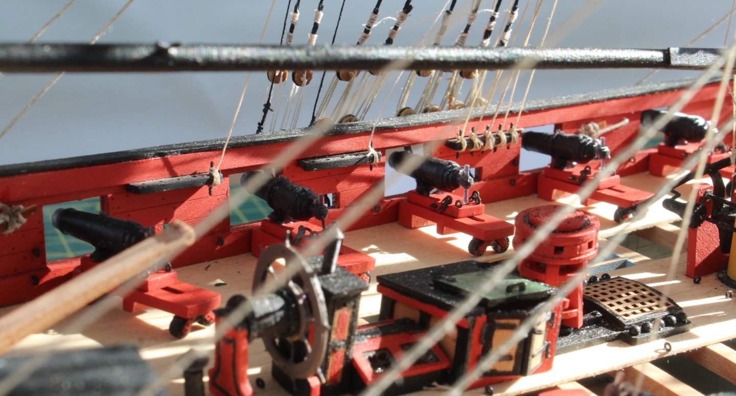
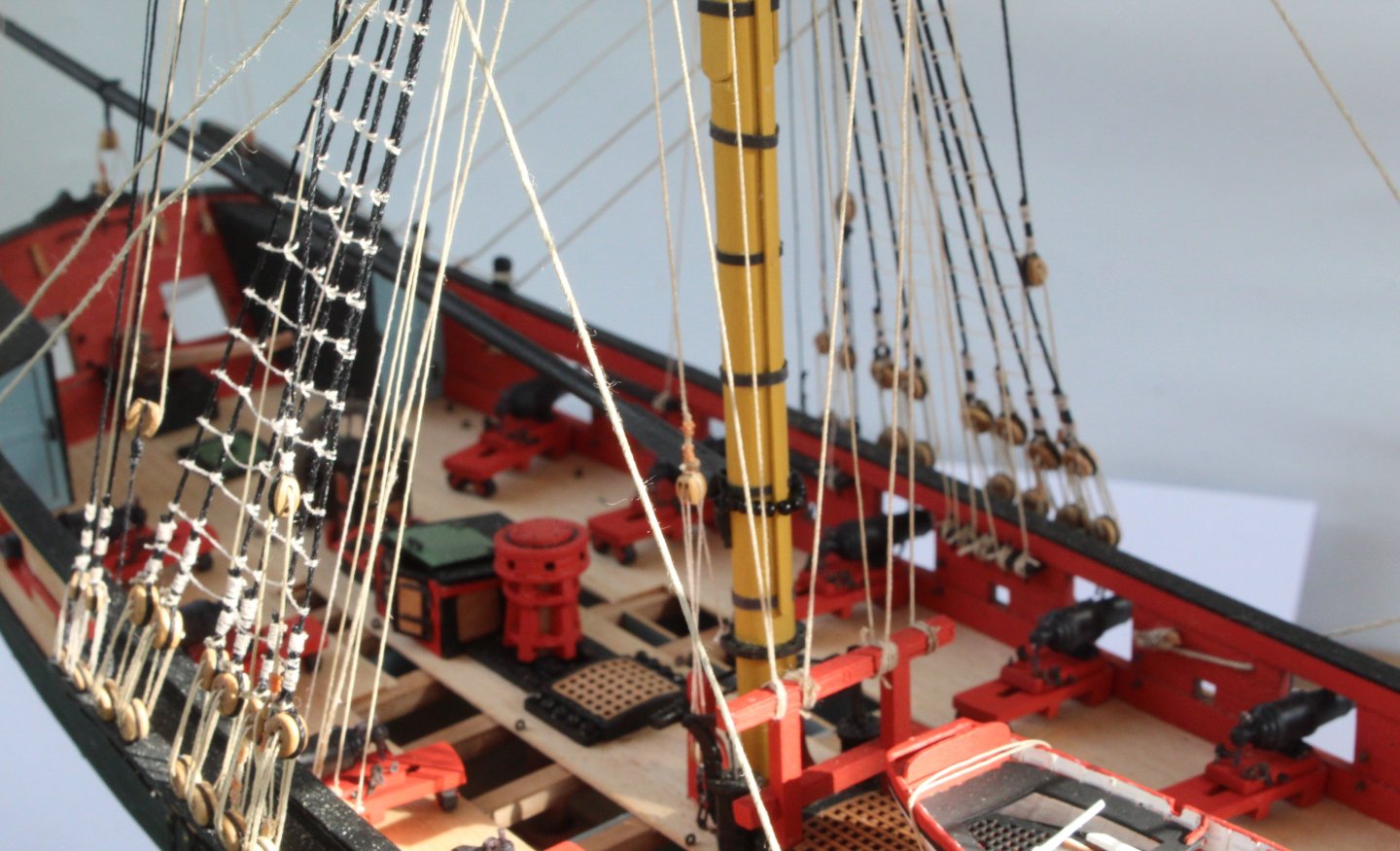
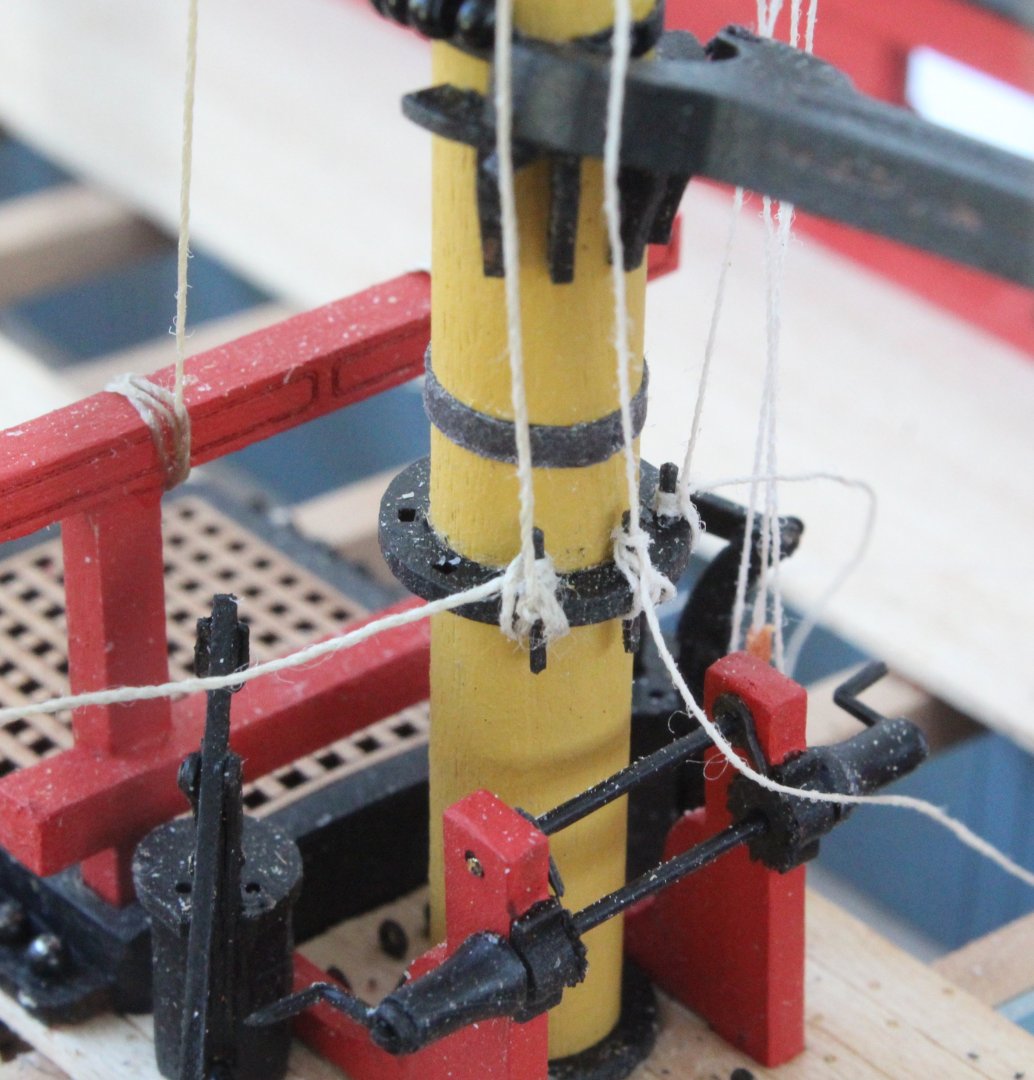
 I have continued to work on building up some of the deck items and I will continue with this approach for the time being before returning to the hull assembly. All the hatches have now been assembled. The coamings are only dry fitted at the moment as I intend to paint the hatch frames black. The ladder was probably the easiest assembly of this type I have assembled. I have also assembled the binnacle (eyebolts to follow) and the capstan. My current thinking is to apply a varnish finish to the binnacle and to maybe to paint the laser etched decorative patterns black, red or green. I will probably paint the lower section of the capstan black and to paint the top section red or green. The top circular infill will be painted black. I have assembled the ships wheel PE parts and have done a dry fit of the ships wheel assembly, as can be seen in the the two photos below. I have also ordered a 24mm Ships Wheel from Syren which is currently on it way to the UK from the USA. I can then make a decision which ships wheel I prefer. I have also order the boxwood elm tree pump kit from Syren. I can then decide which pump assembly I prefer when it arrives. I might even amalgamate the two pump kits. I have also ordered a serving machine and a set of the 3D printed rigging blocks and deadeyes from Syren as I am keen to try adding served shroud and stays when rigging. I do particularly like the look of the 3D printed deadeyes so thought I would it was worth getting a set for this build to try out.
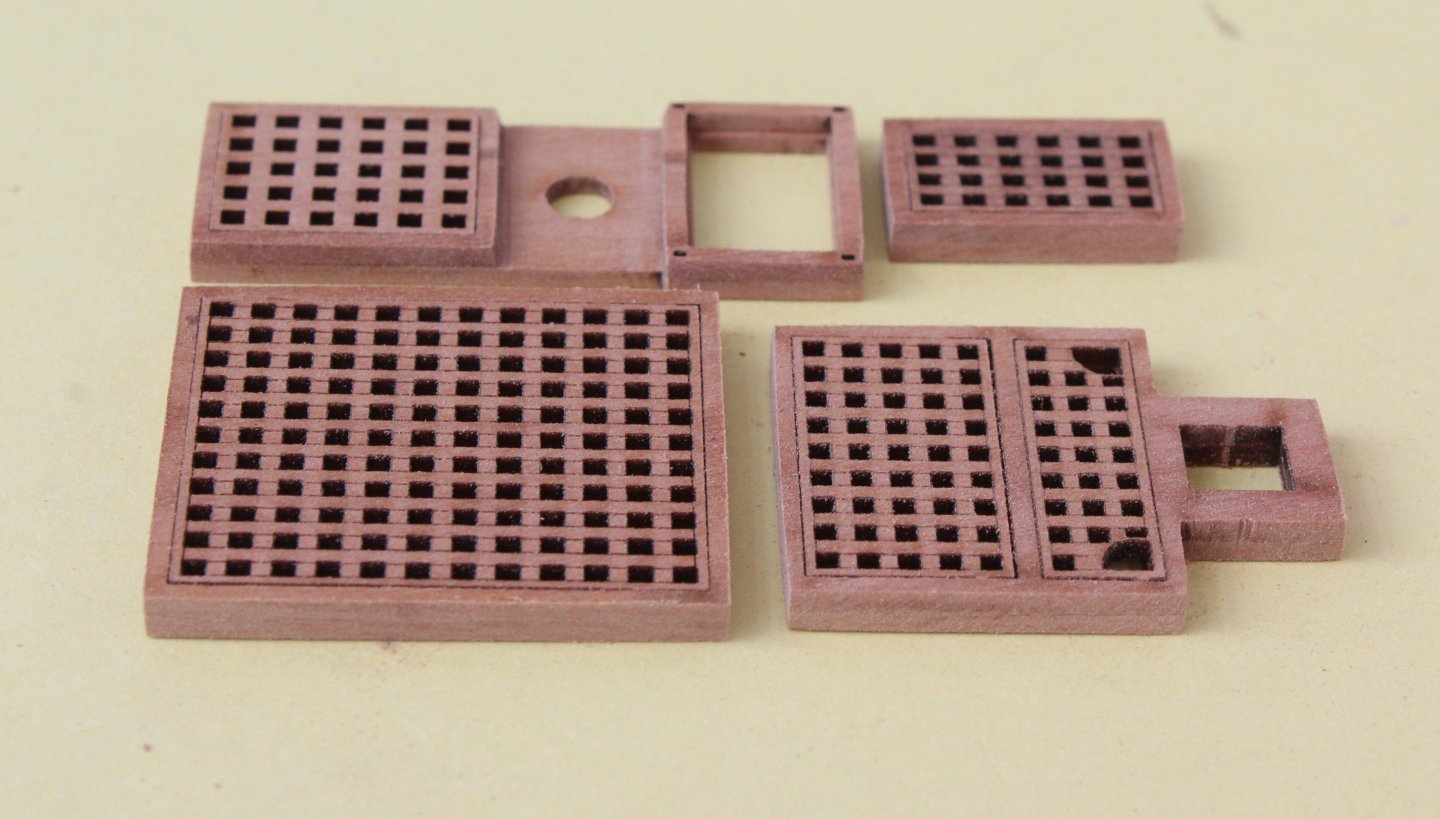

-
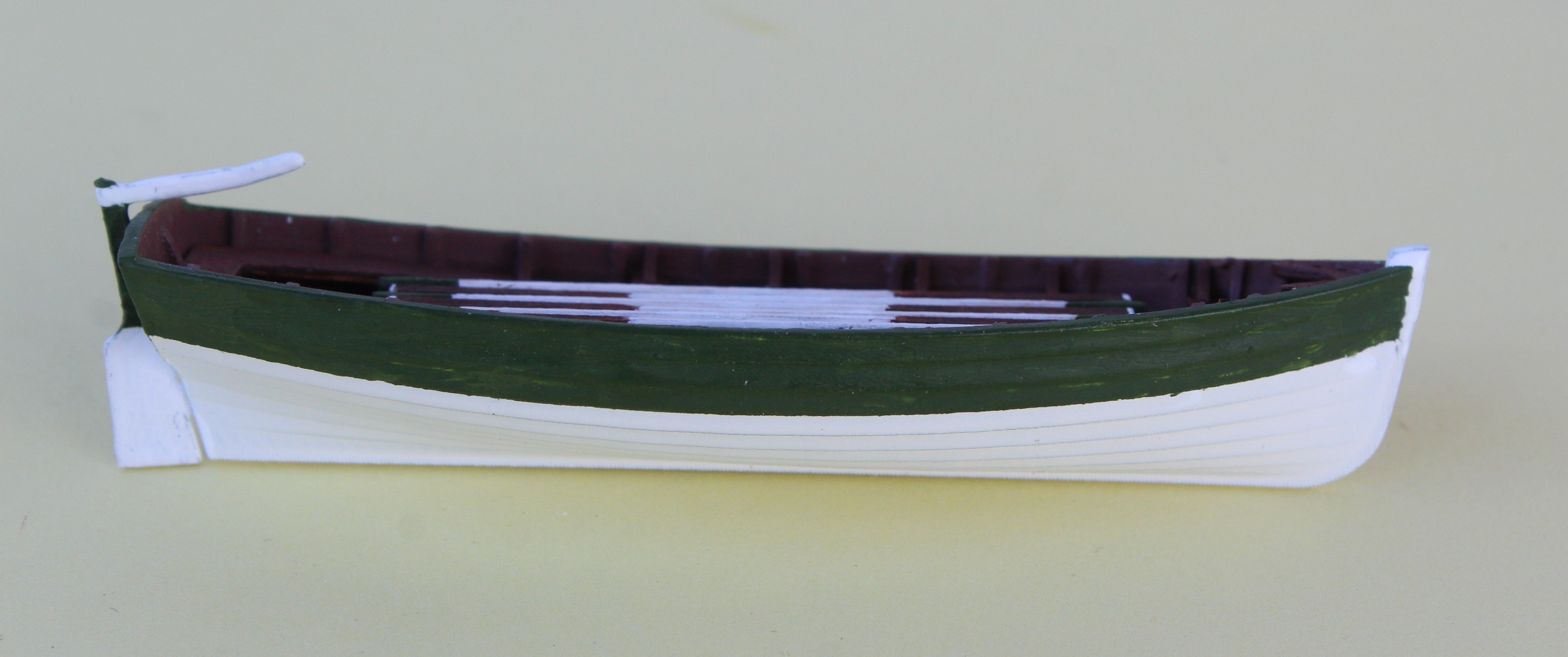
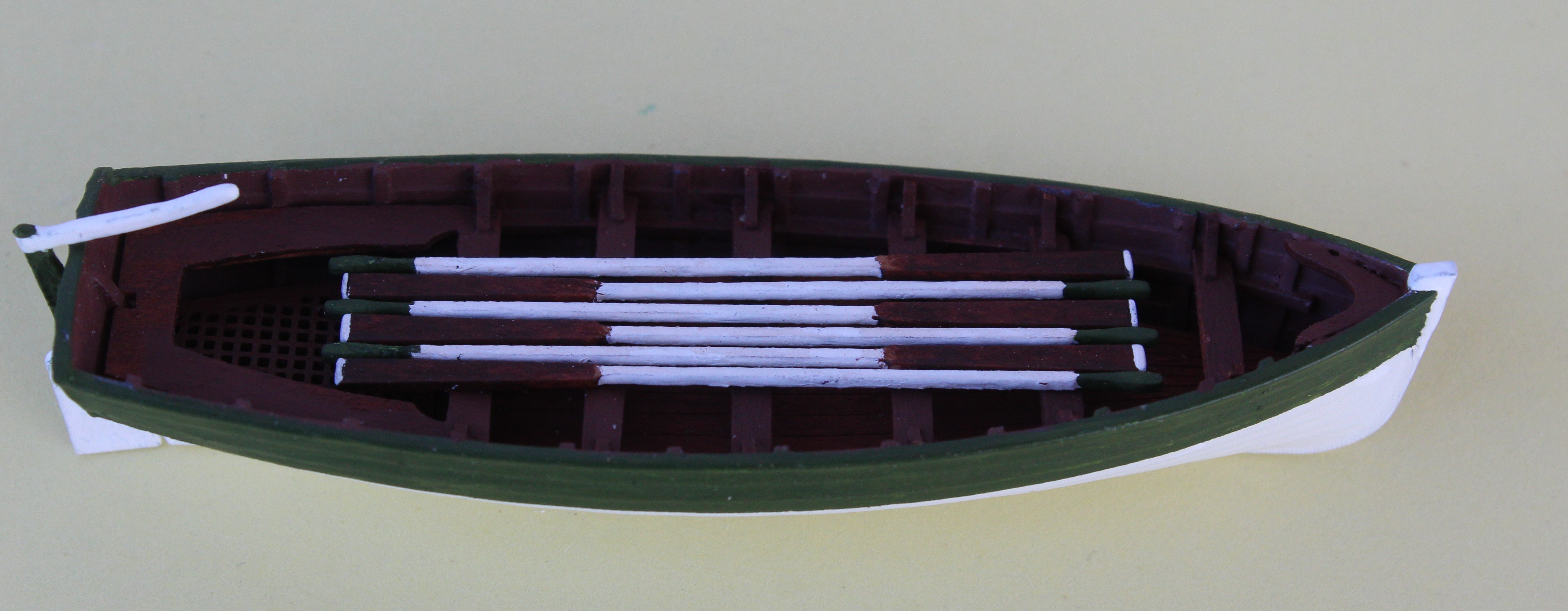
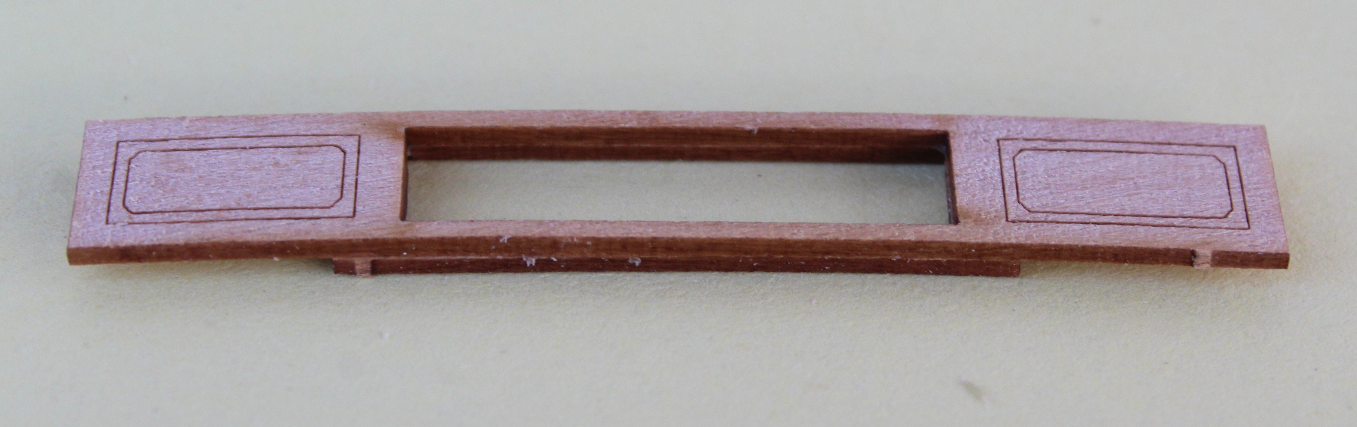
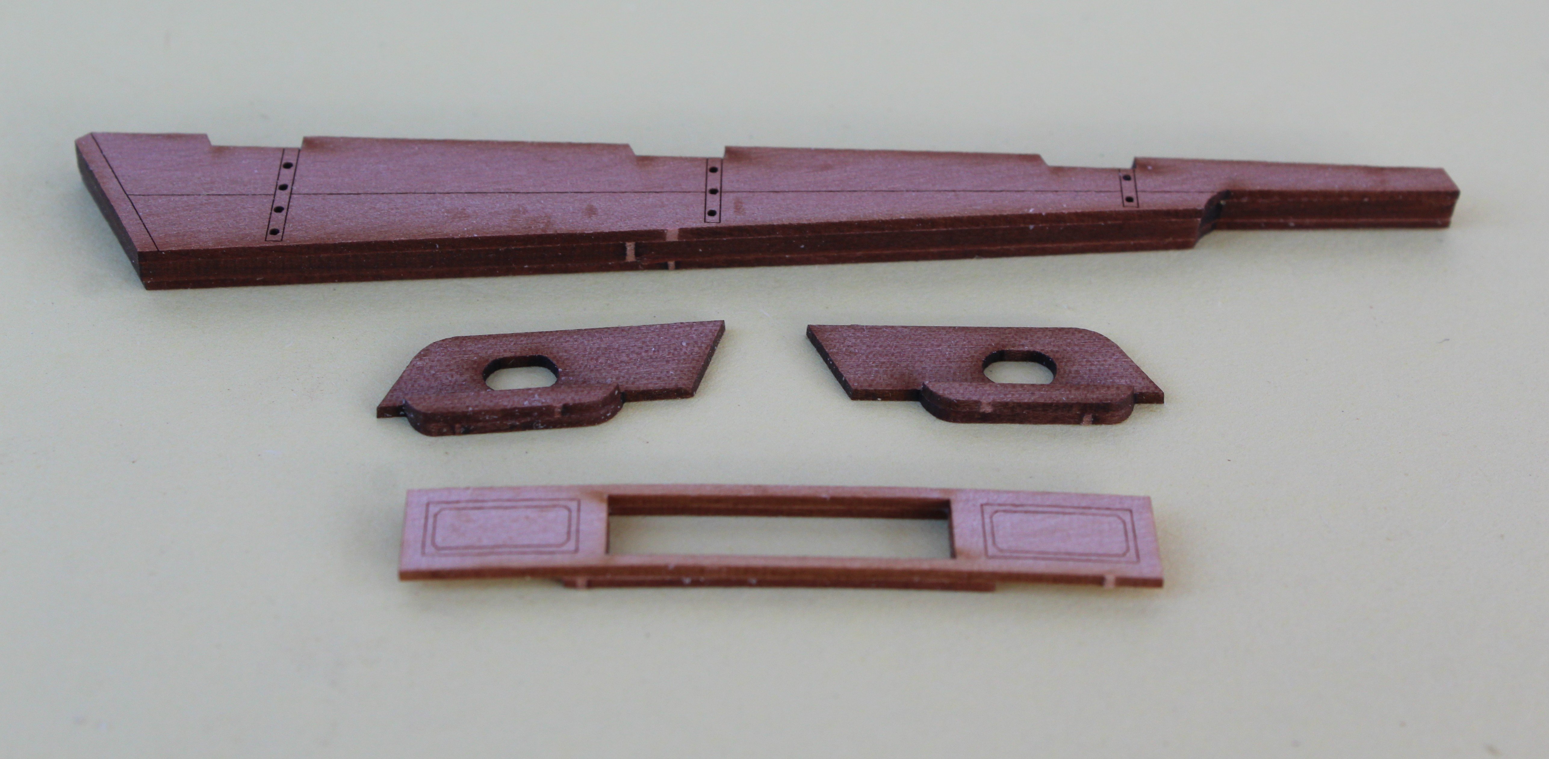
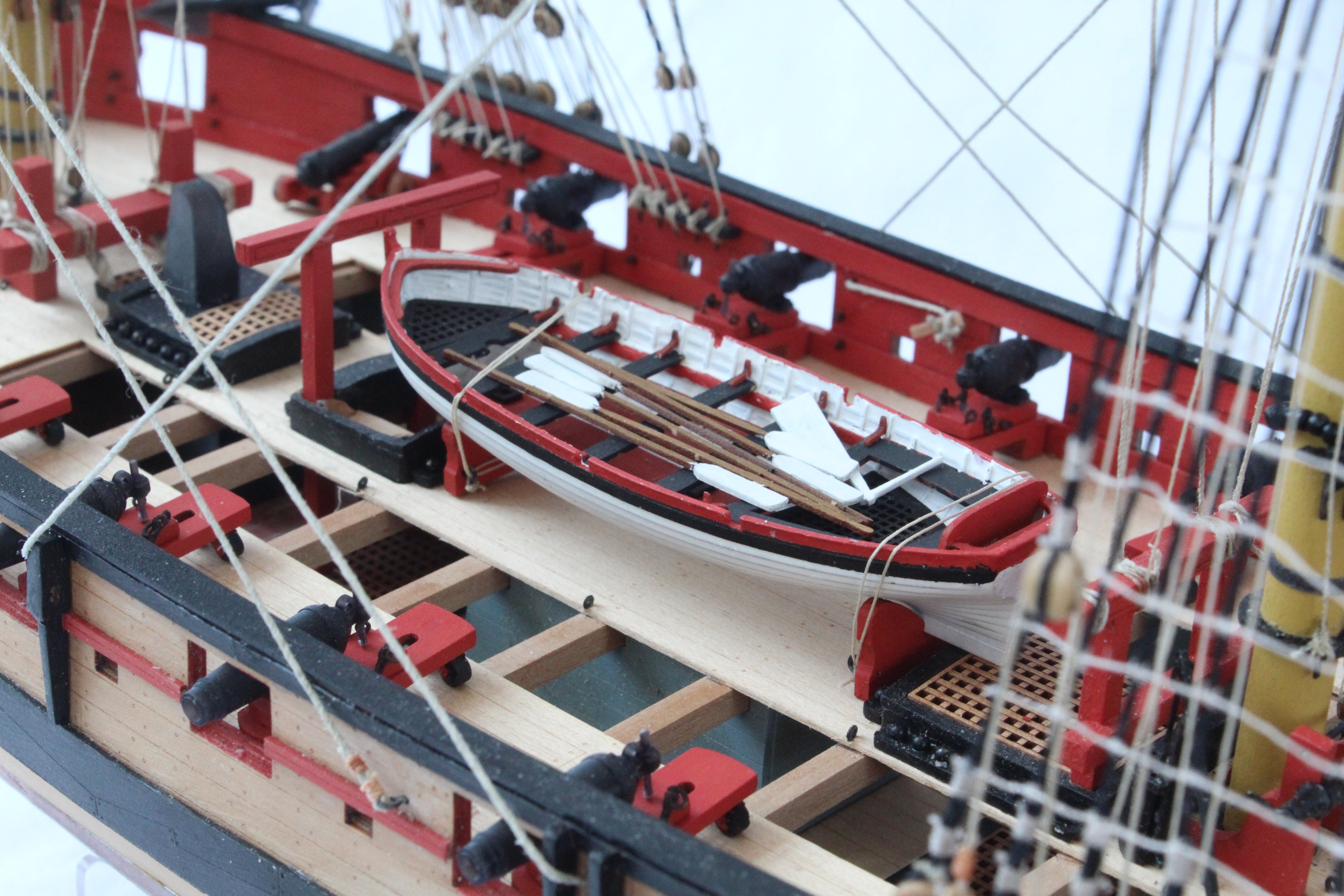
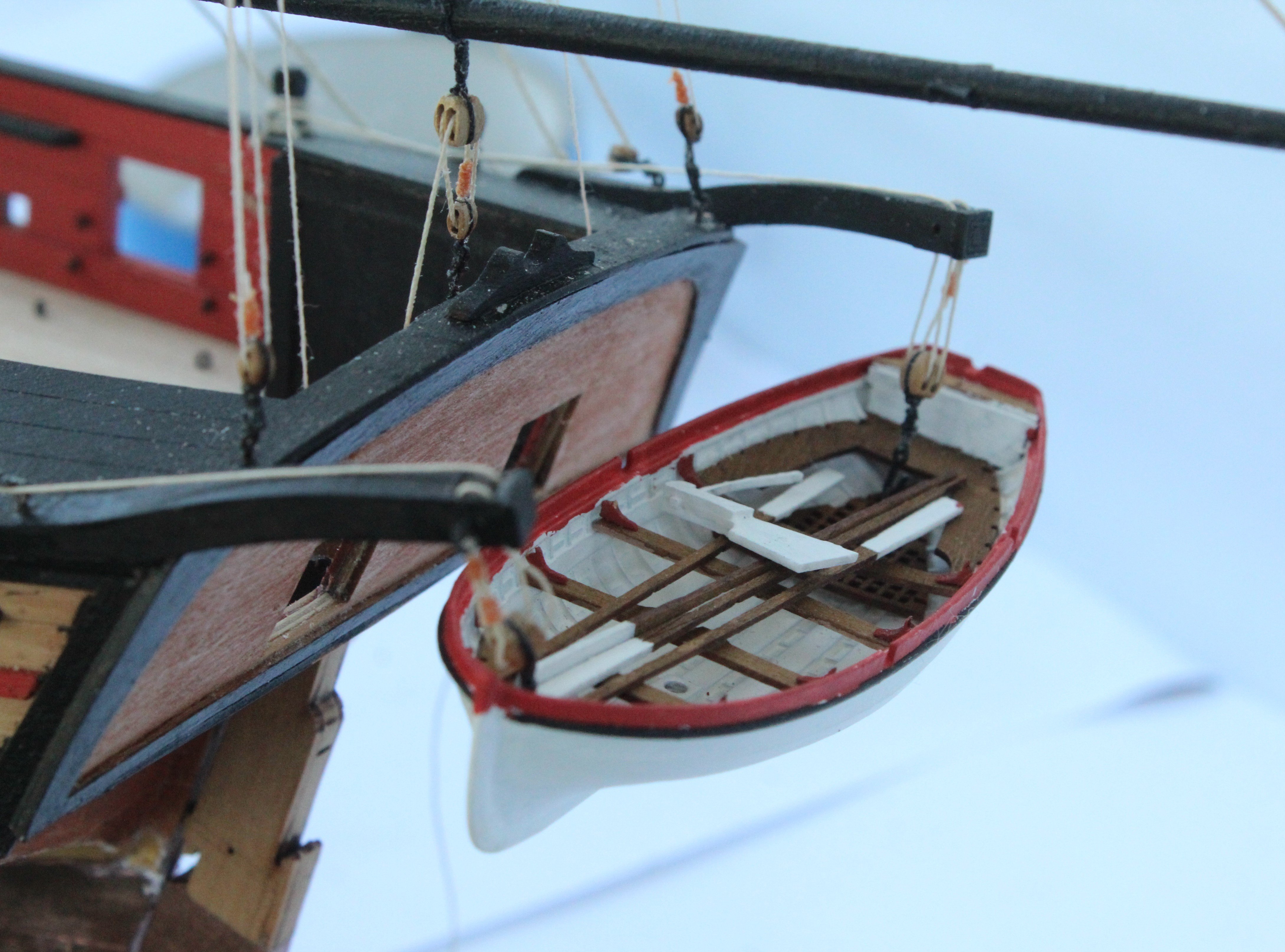
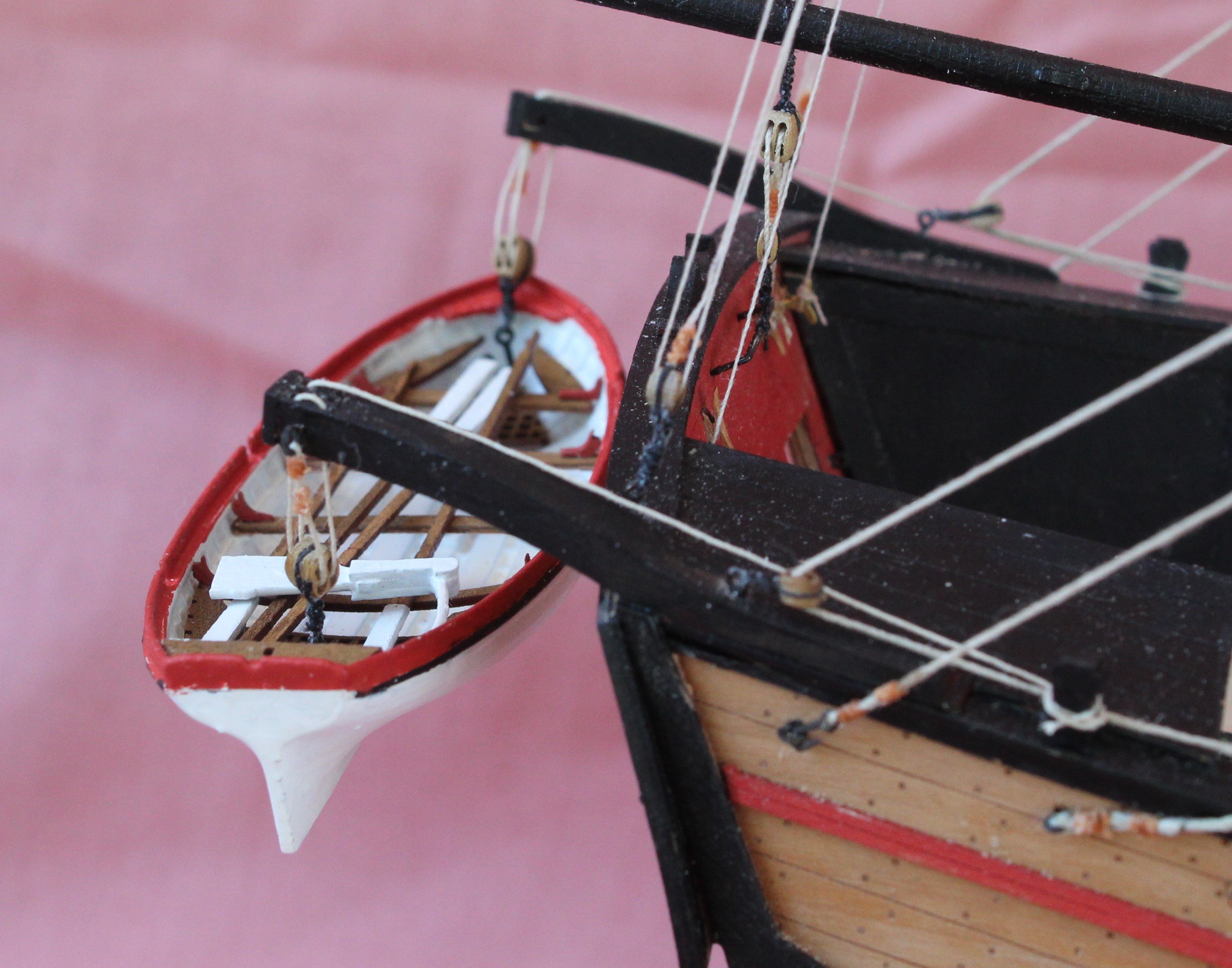
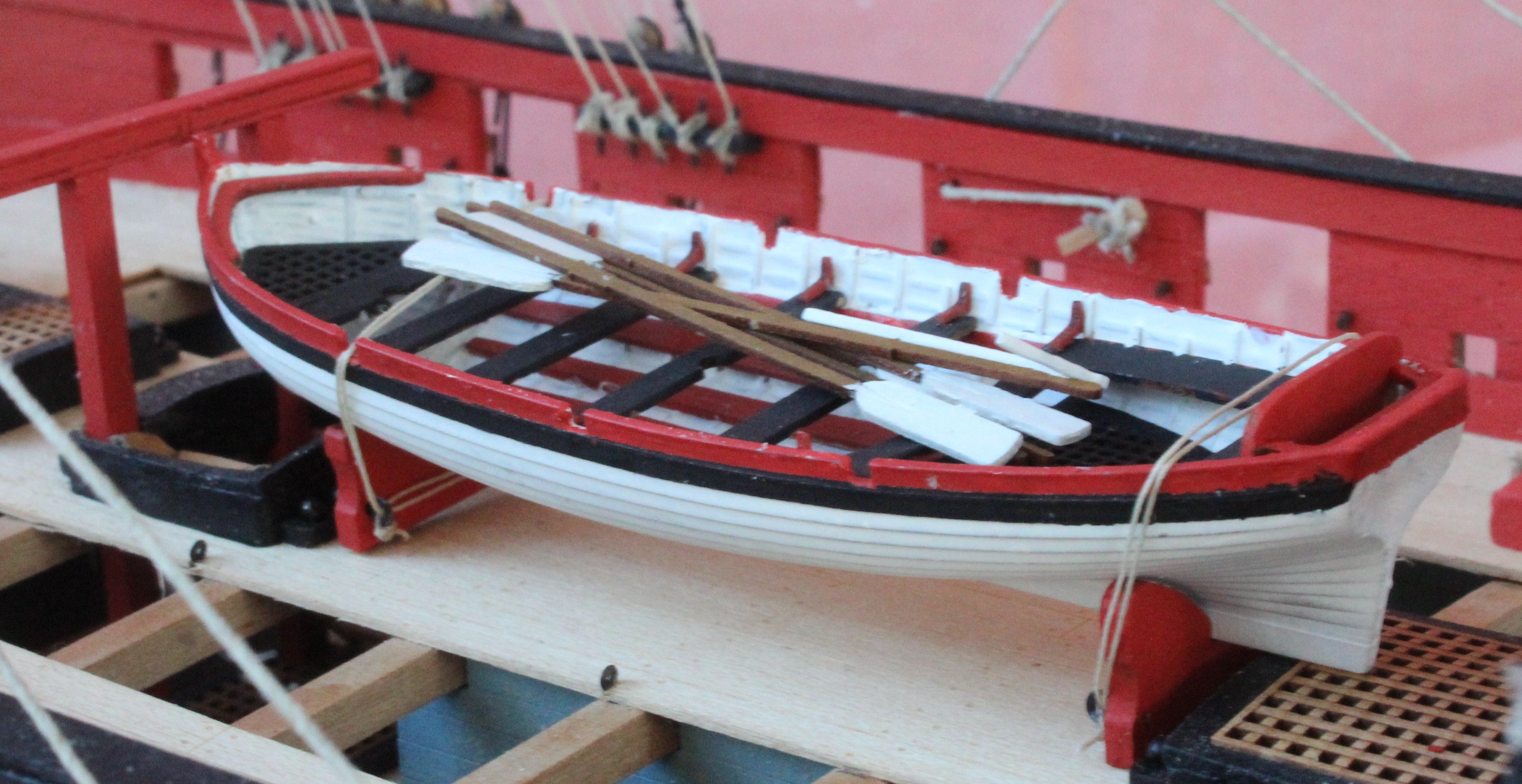
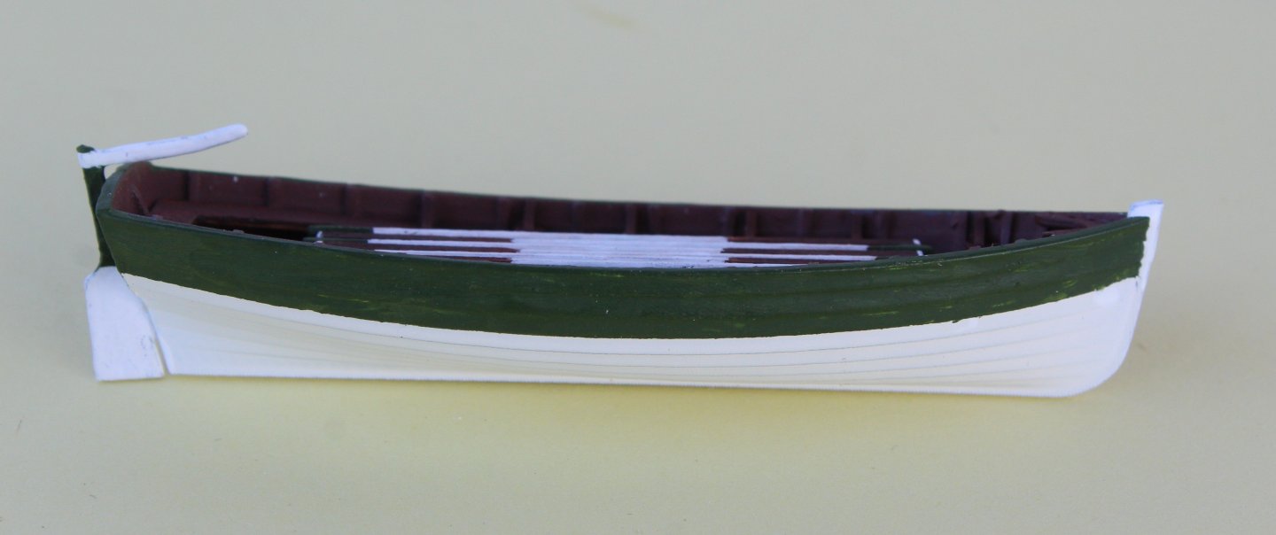
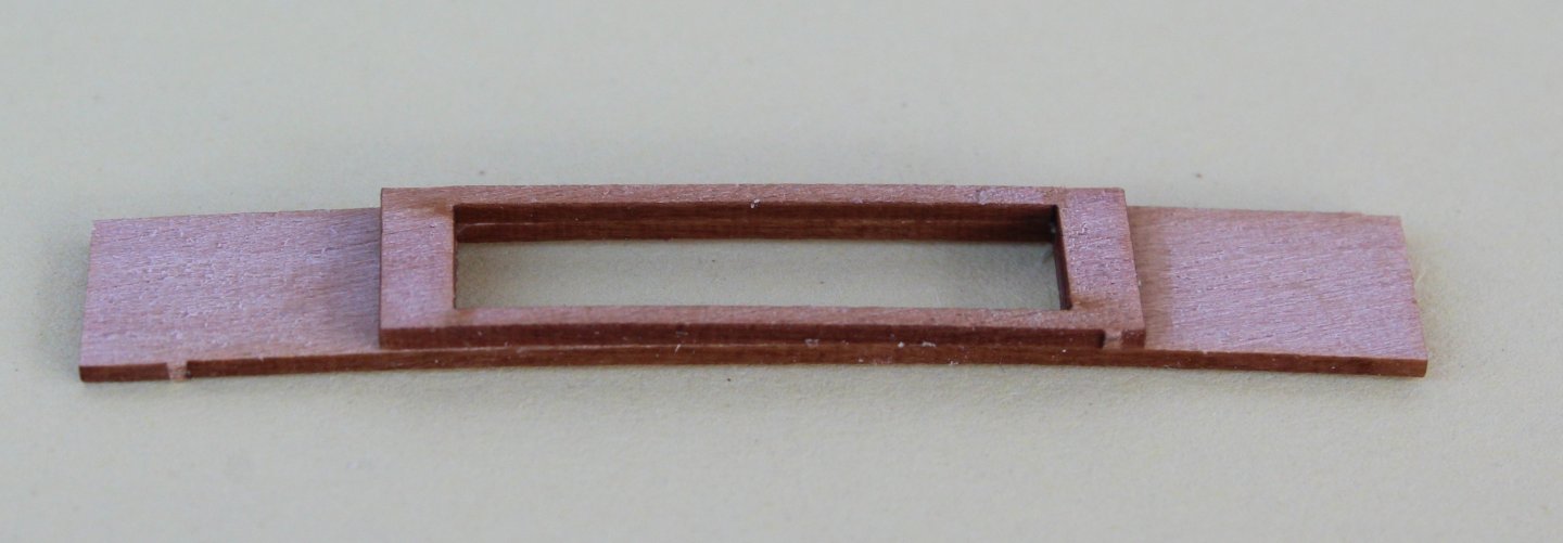
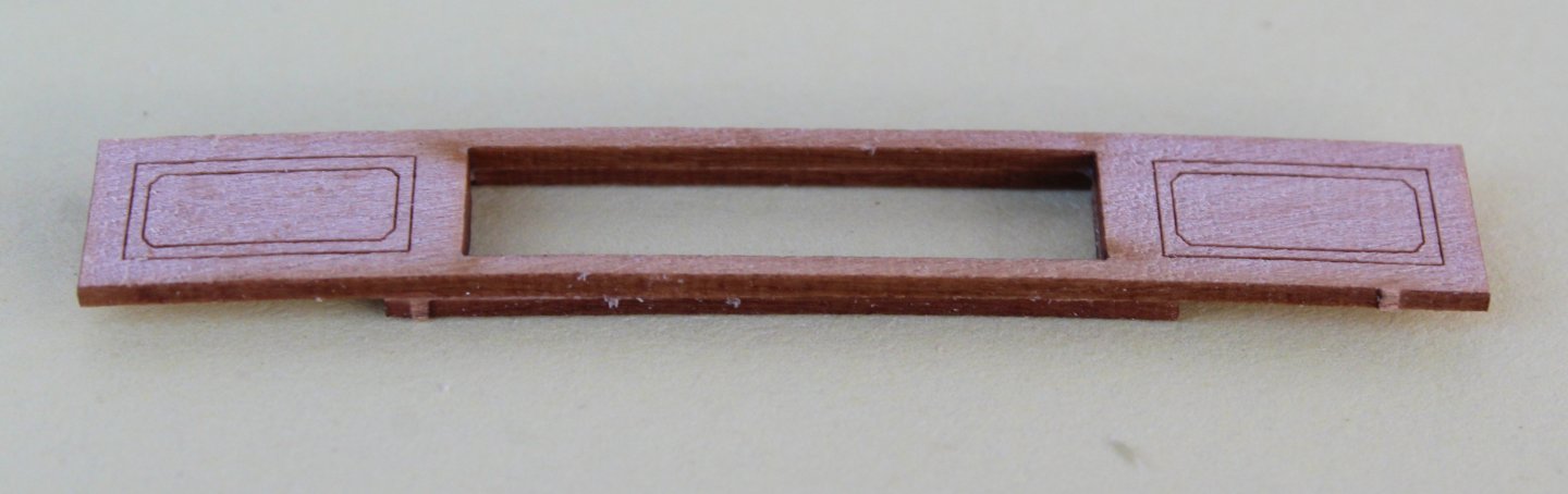
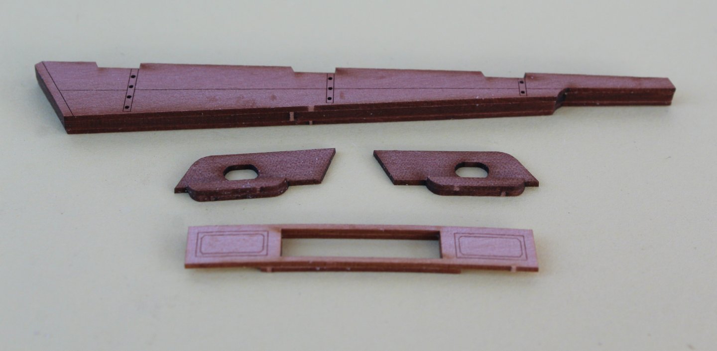
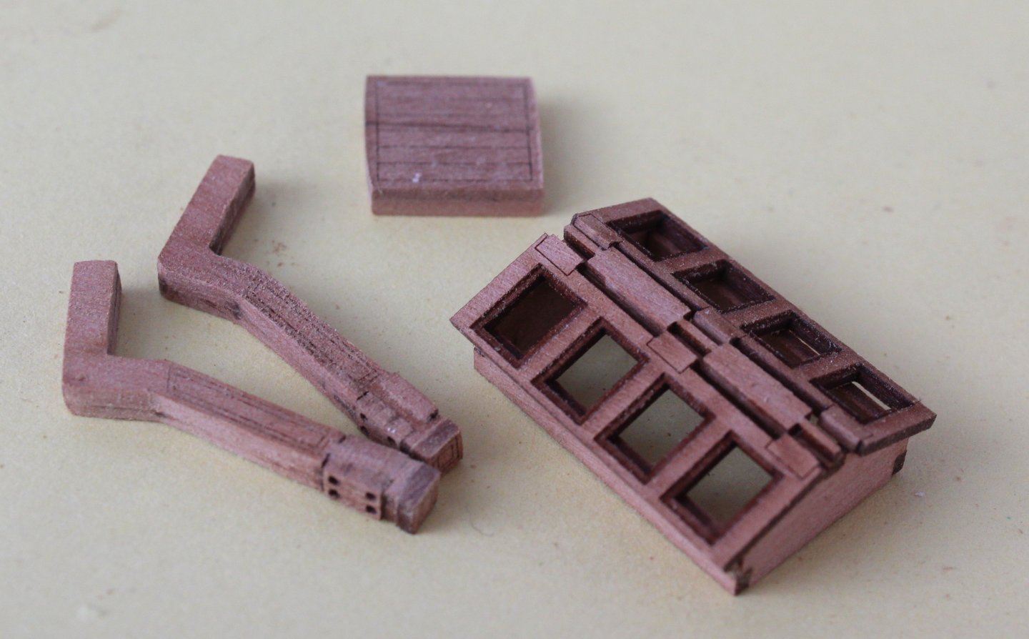
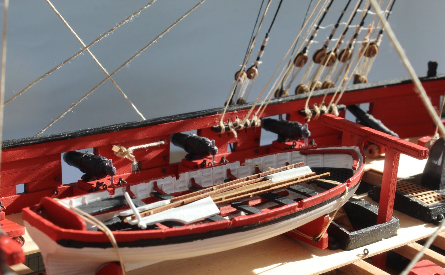
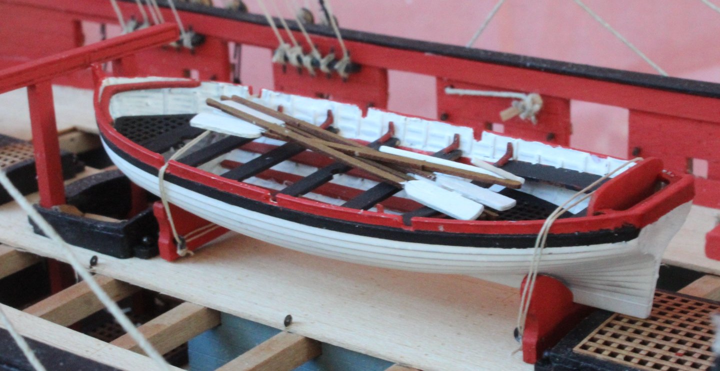
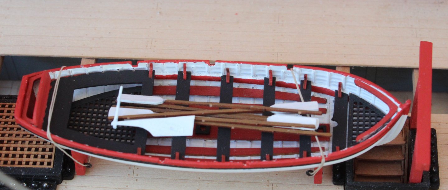
I have finished building and painting the 20ft cutter. As you will note I have added the white tips to the oars. I am really pleased with the end result. The tiller housing comprises an inner and outer pattern which have to be aligned and glued together. I took great care to ensure the parts were properly aligned and once I was happy the parts were clamped whilst the glue cured. I then moved on to adding the hawse bolsters to the hawse patterns and the outer patterns to the rudder. I used some pins to ensure the rudder outer patterns were correctly aligned. Next I assembled the catheads swiftly followed by the bread hatch. Finally I built the skylight frame. In the photo below the skylight window frames have be placed in position but they are not glued in place as I have not decided on the finally colour scheme for the deck items.

-
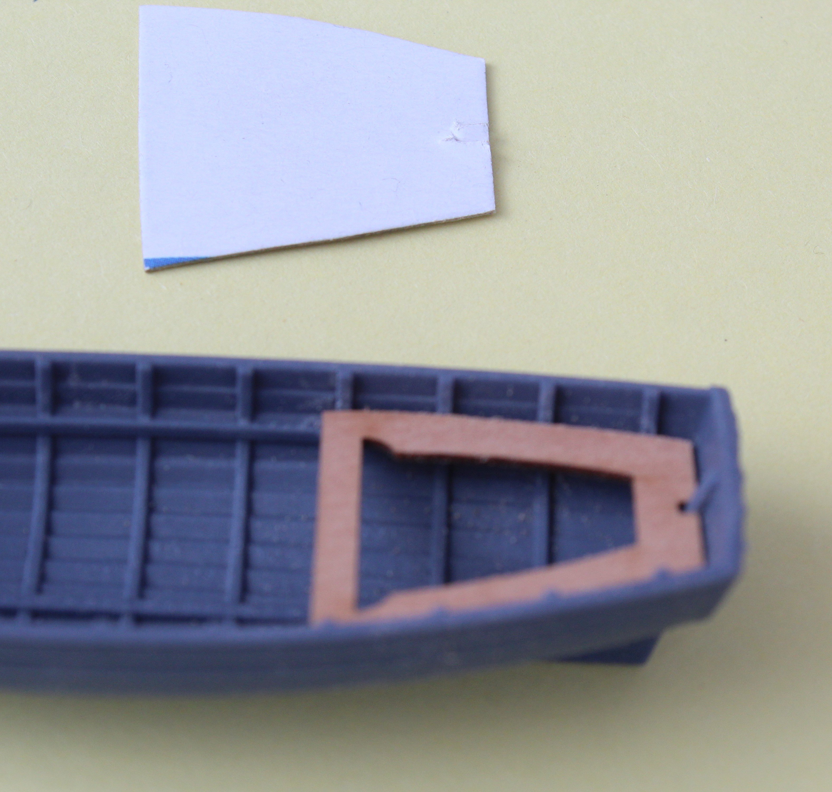
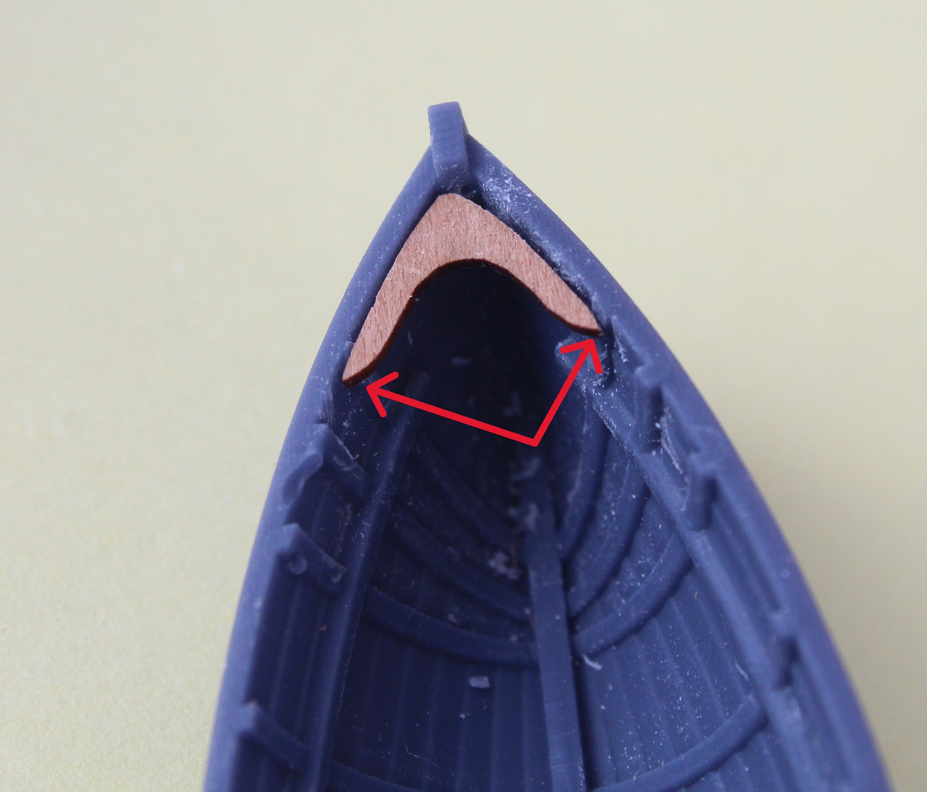
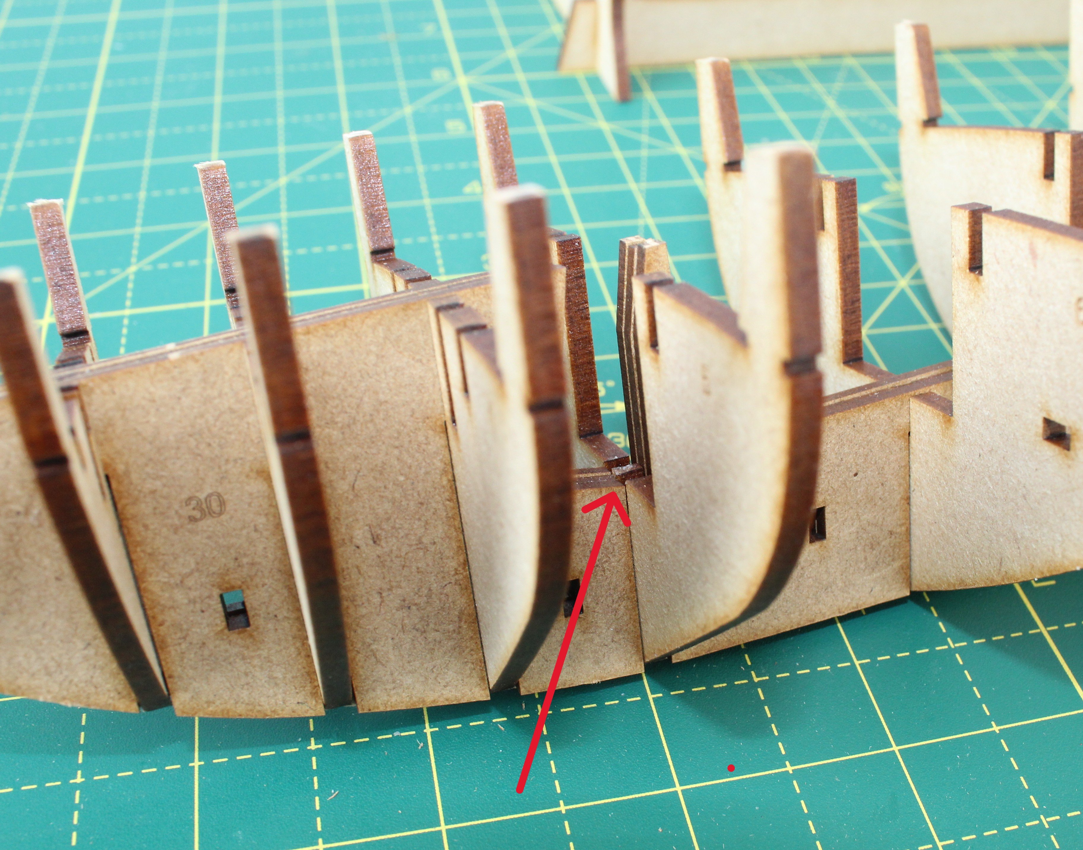
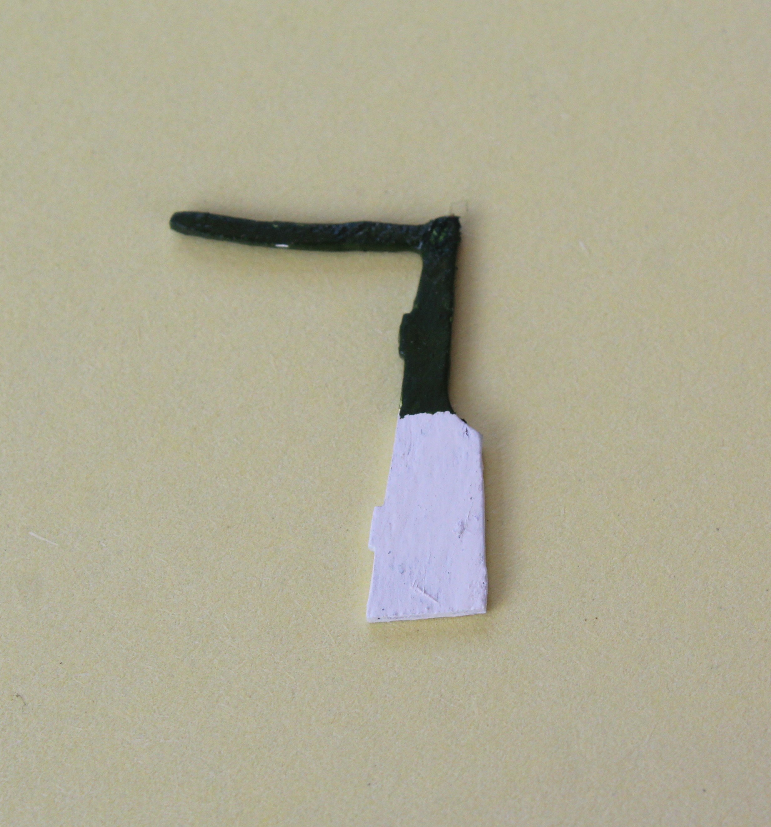
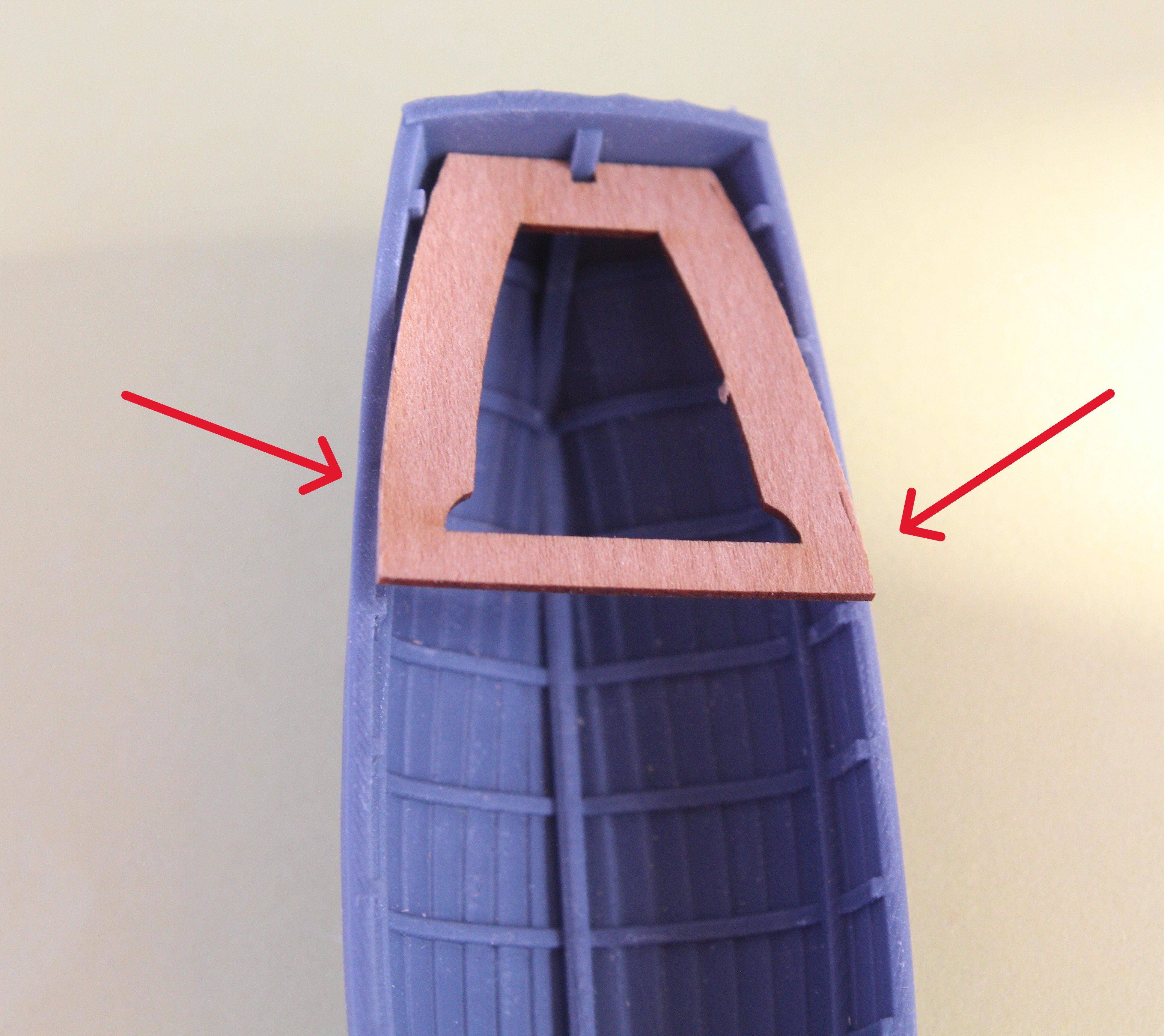
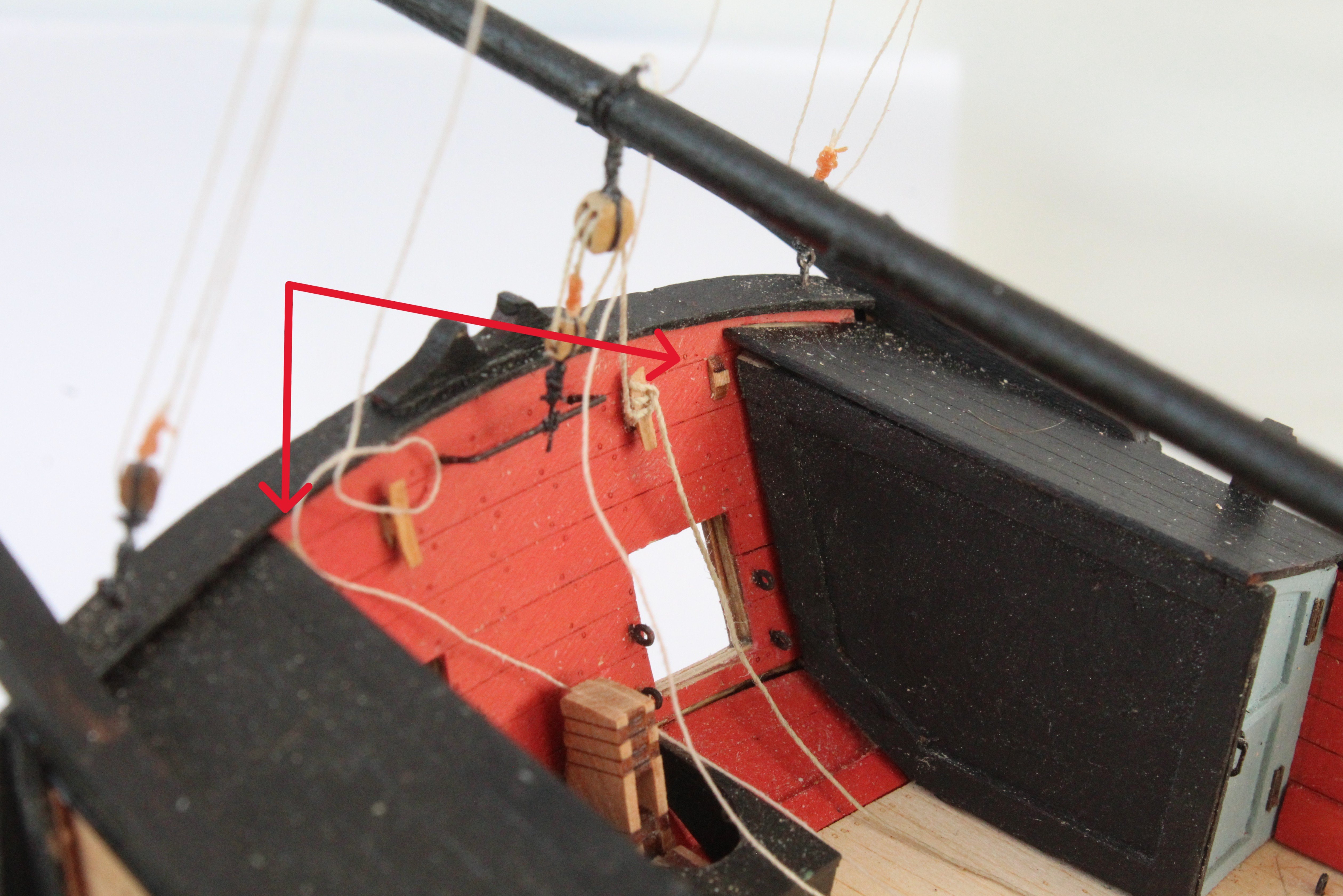
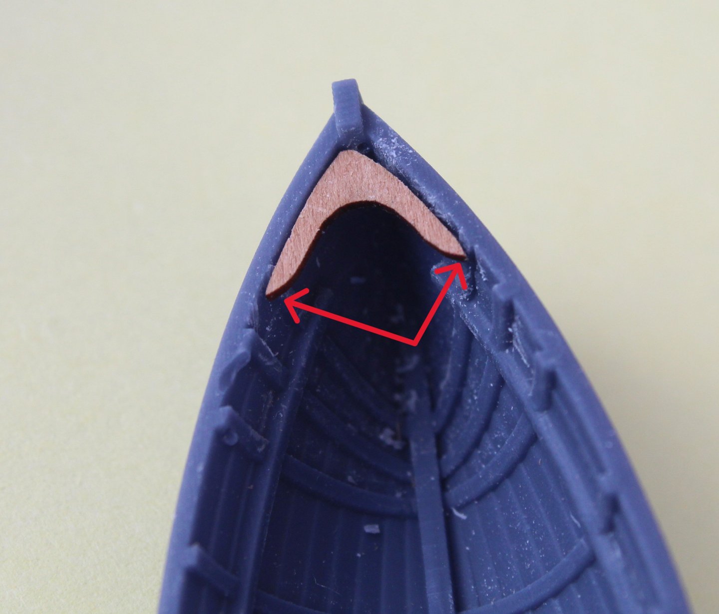
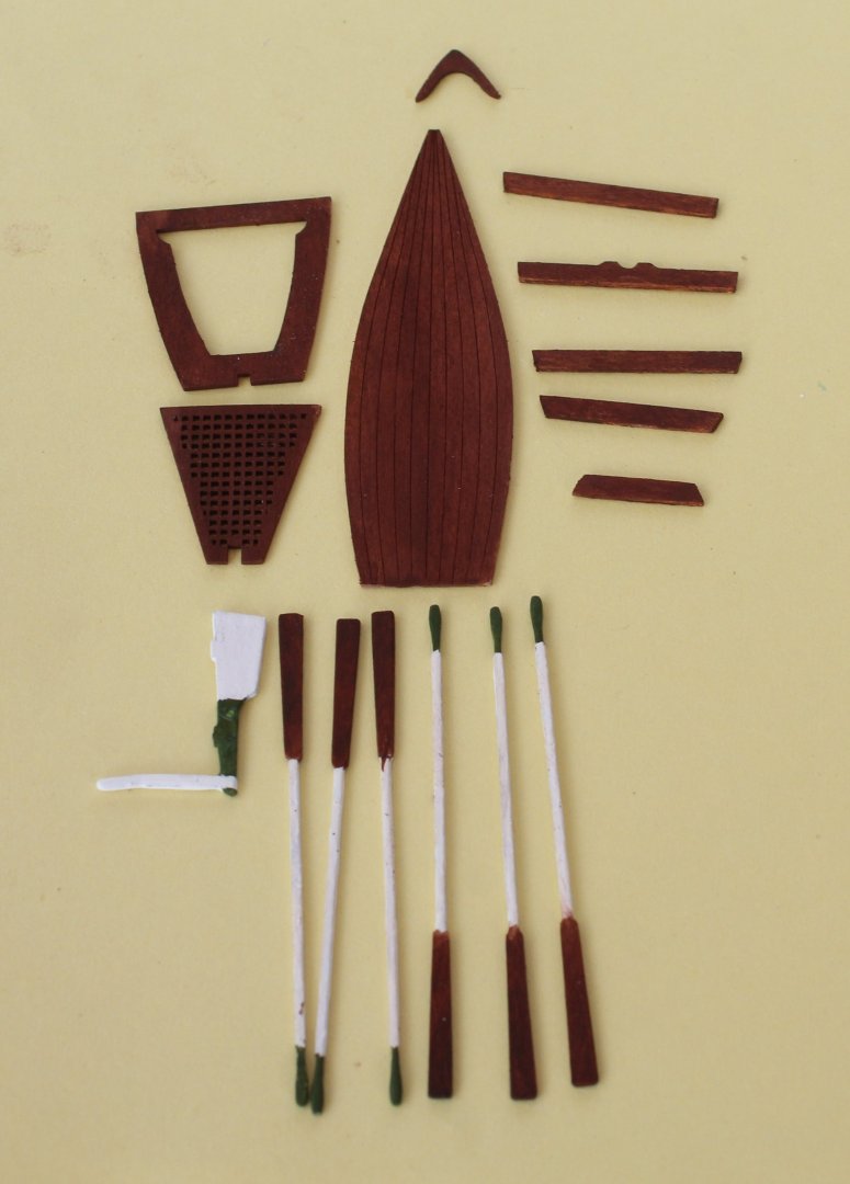
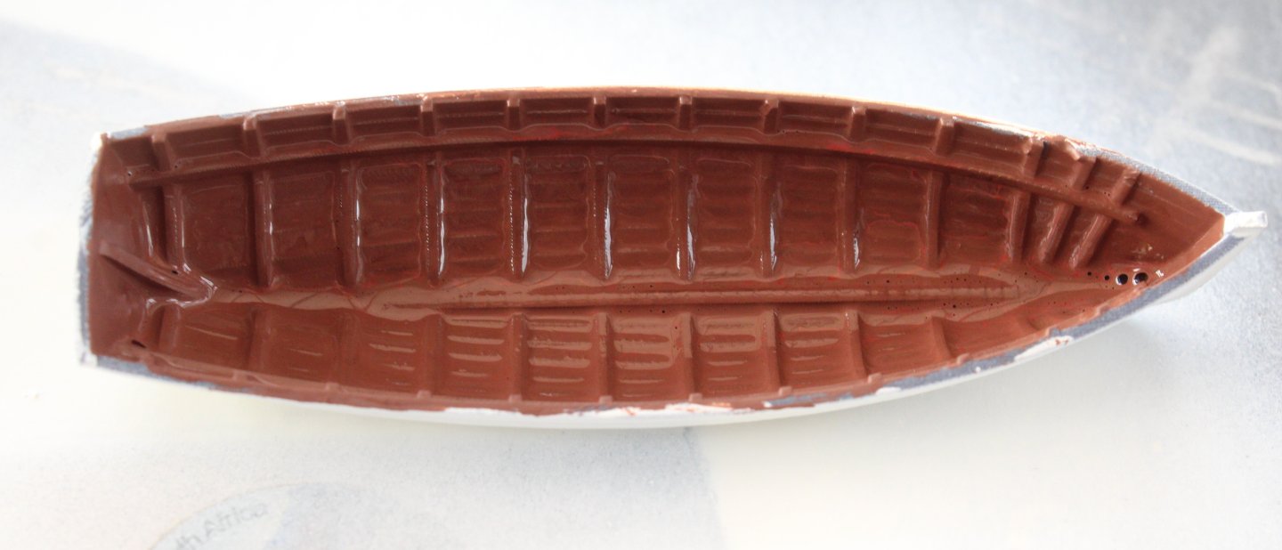
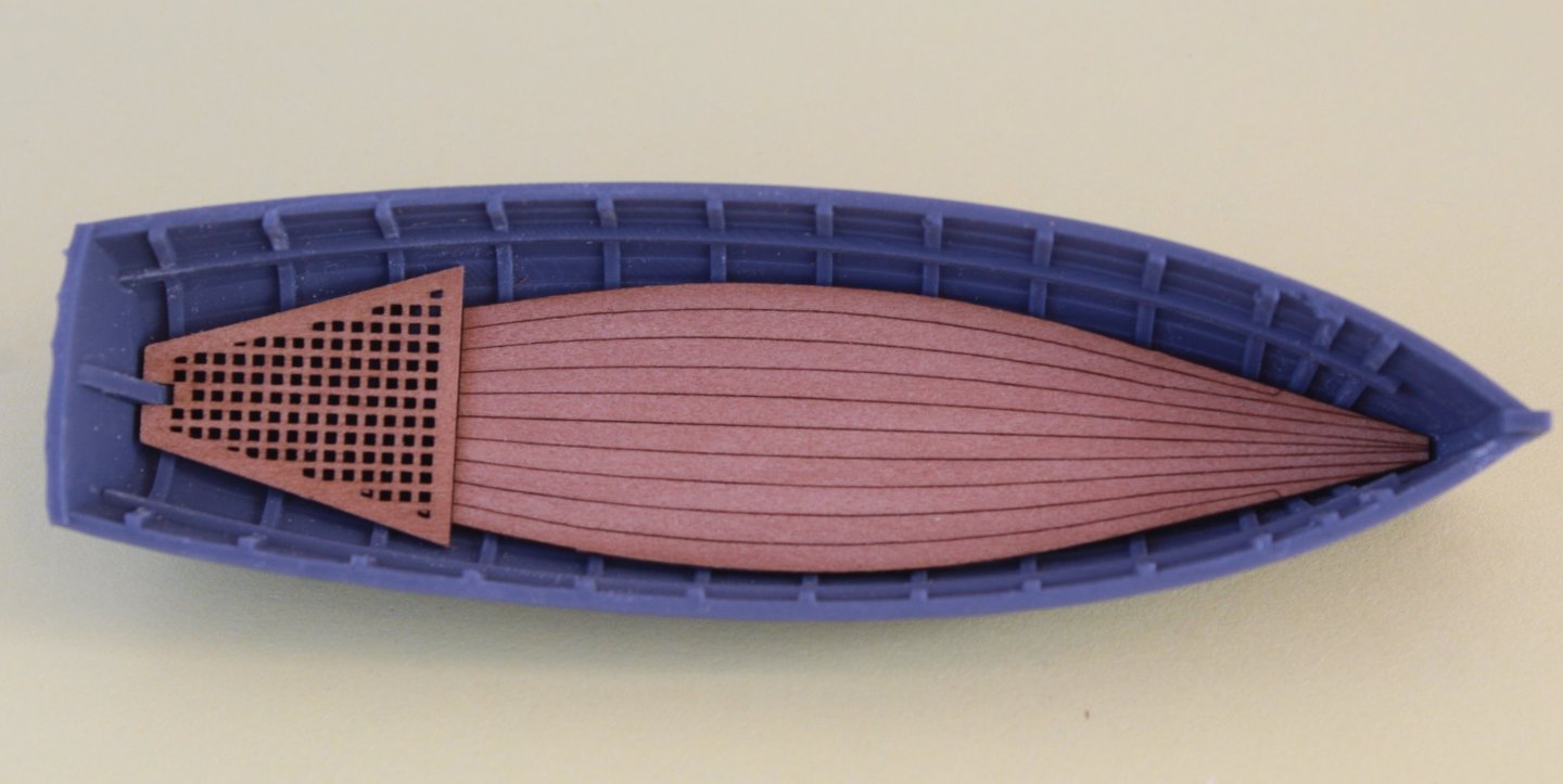
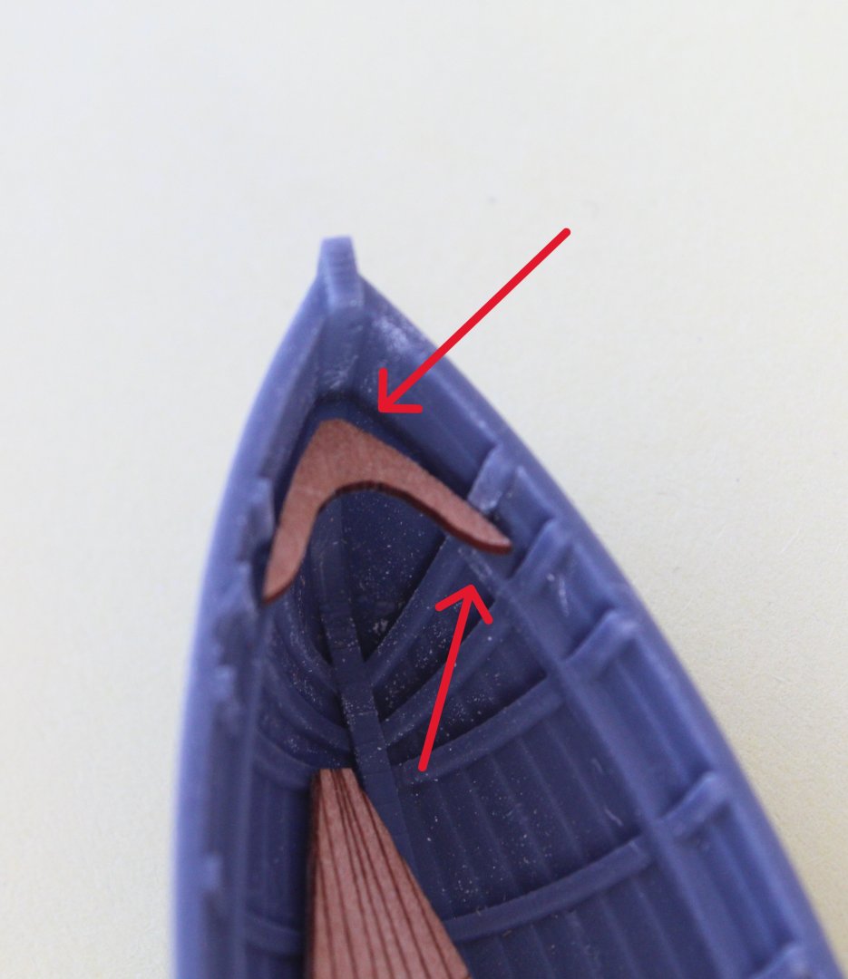
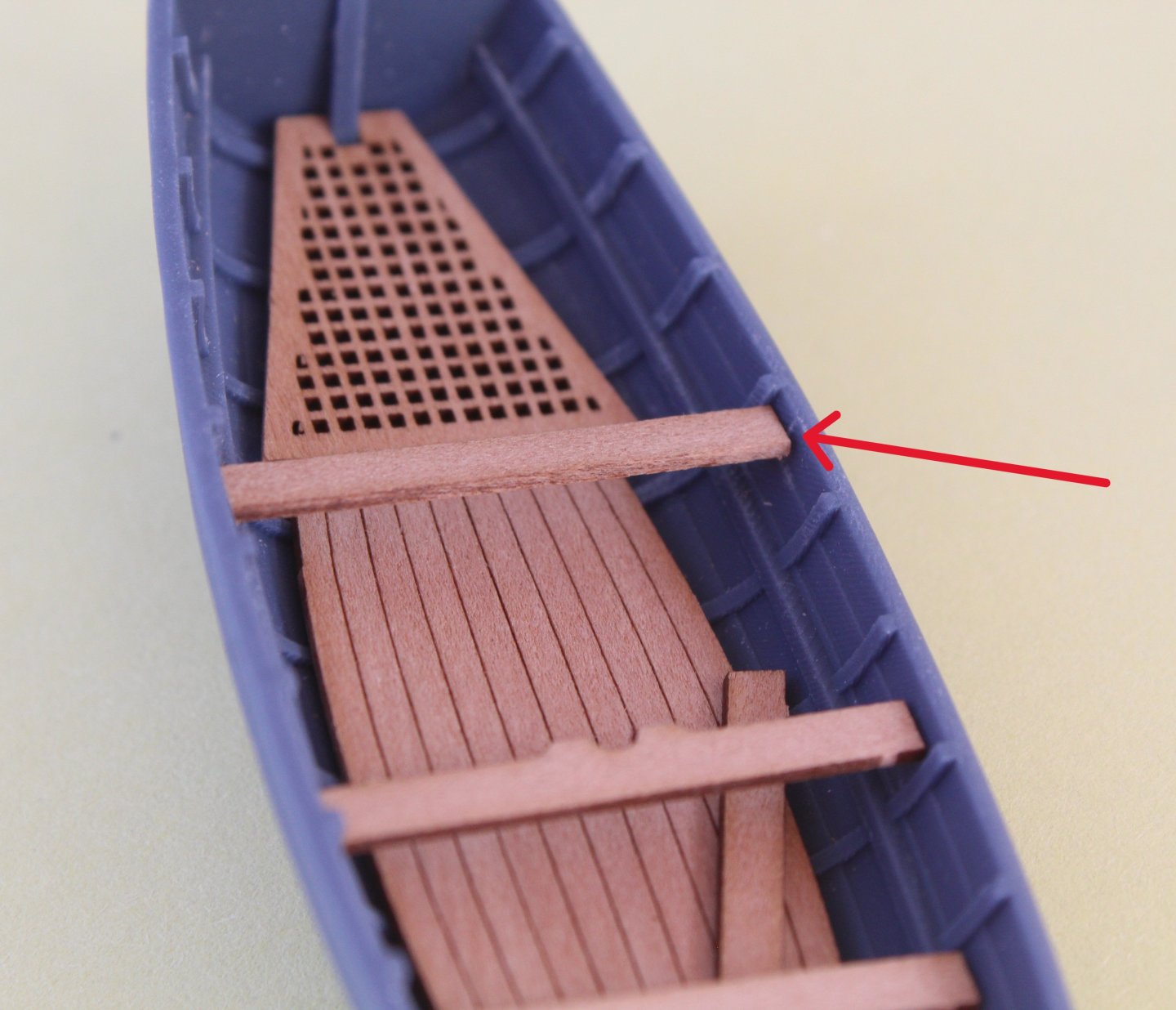
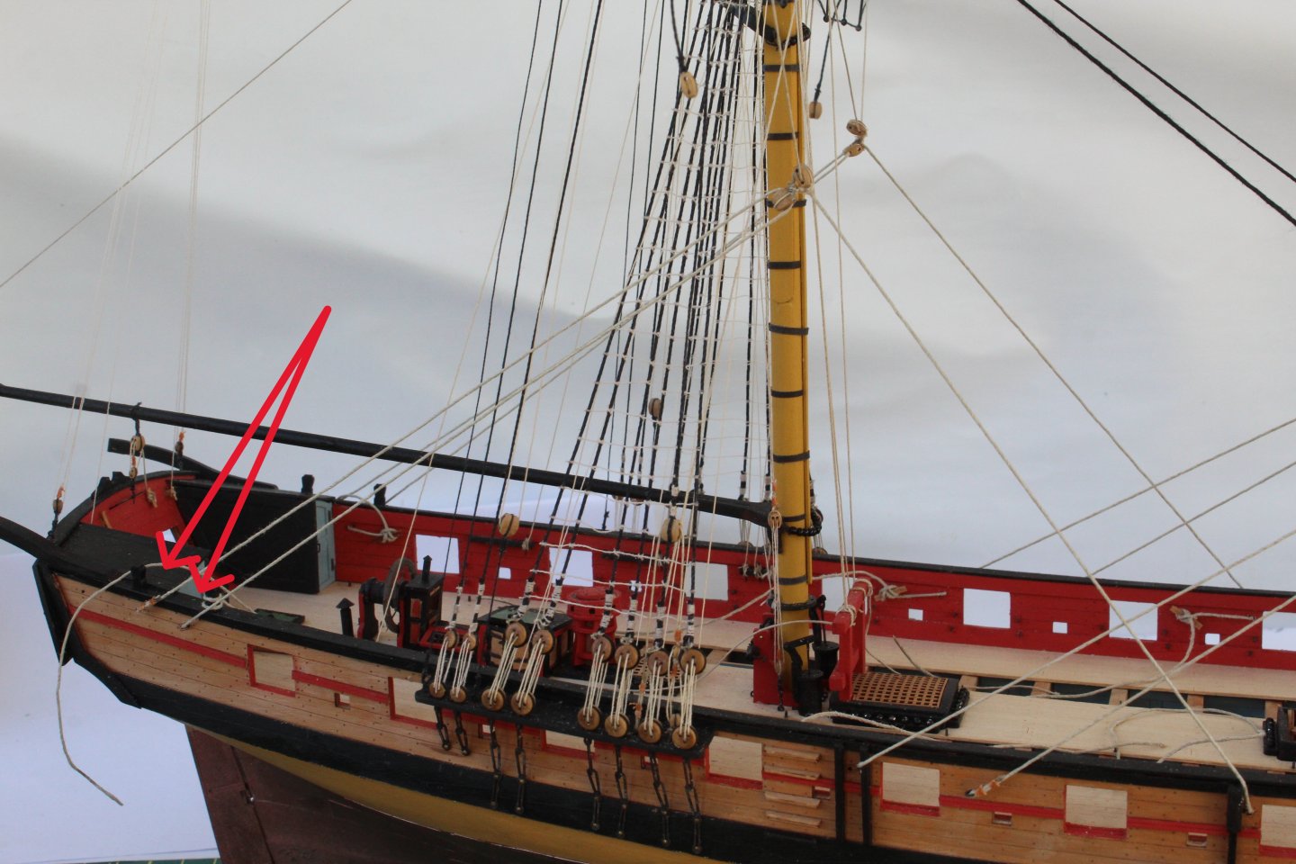
I have spent a bit more time working on the 20ft cutter today. I made a cardboard template of the stern sheet (rear seat). Once I was happy with how the template fitted I was able to adjust the actual part so it was a good fit. Next I removed the top section of the leading 3D printed bulkhead (red arrows in the photo below) to aid the fitting of the bow knee. When sanding the laser char from the rudder the tiller arm did break off into several small bits. I was able to make a replacement tiller which was glued in place. You cant see the join in the photo below which is taken part way through the painting process, as the tiller arm will be painted white later on. I have also started to paint the oars, noting the ends will be have a white tip added, as indicated by the red arrow in the photo below. The boat fittings are now ready to be fitted, noting I will need to touch up the white bits on the oars and to also add the white tips. The hull has been painted white, noting the top outer section will be painted green. I have painted the internal hull withe a dark brown. It does look a bit chocolatey but I think it will pass muster when all the deck fittings have been added. I have fitted bulkheads 1 -16 to the keel. The keel inner patterns have also been fitted. I have not fitted the locating pegs which will be the next task. I was a bit concerned with the fitting of bulkhead 5 which sits proud of the top of the keel, as can be seen in the photo below. I did check and confirm the bulkhead was fully seated and when I looked at a photo on Jim's prototype build log I noted his looked the same - phew!


-
Welcome to all the followers.
-
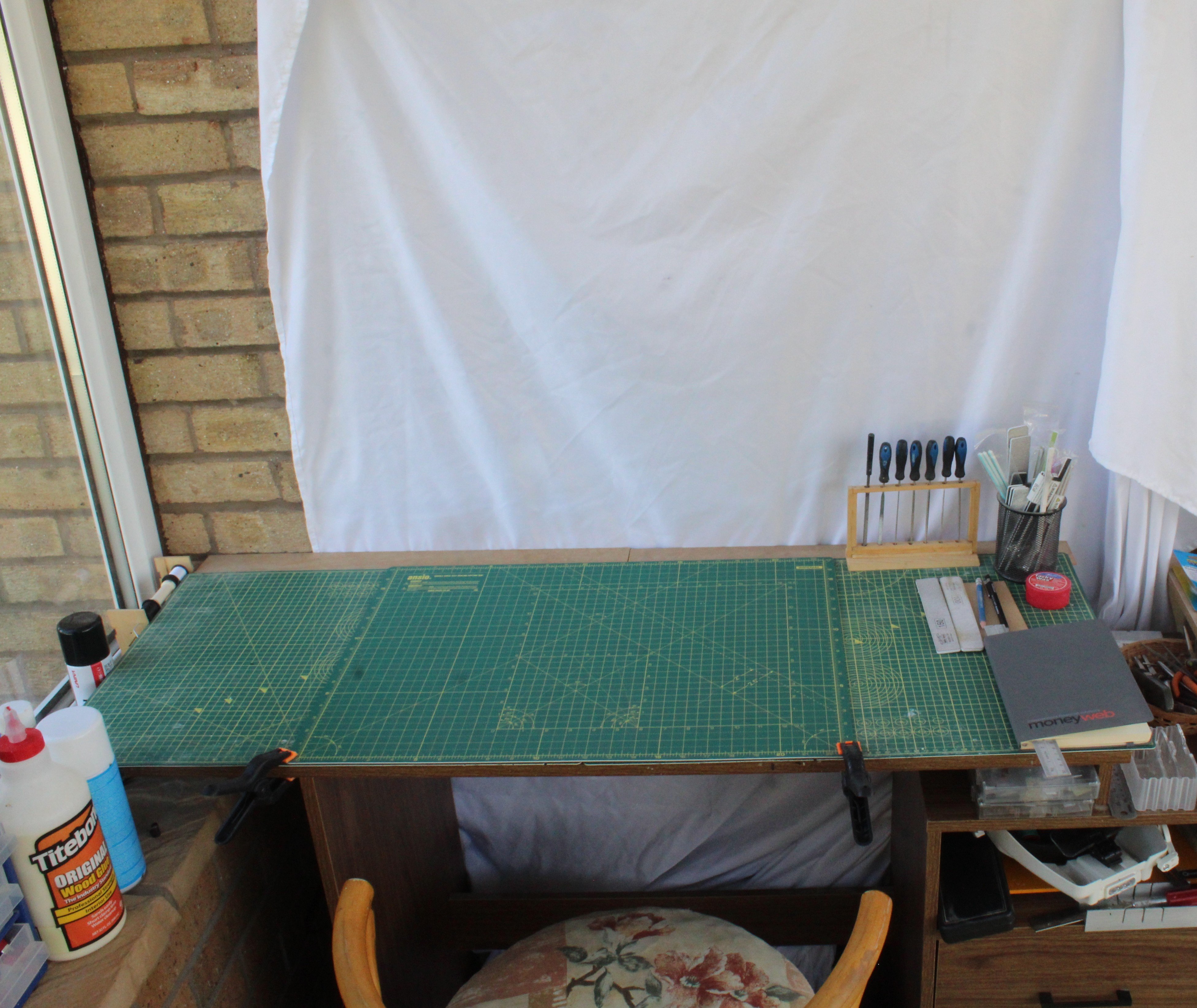
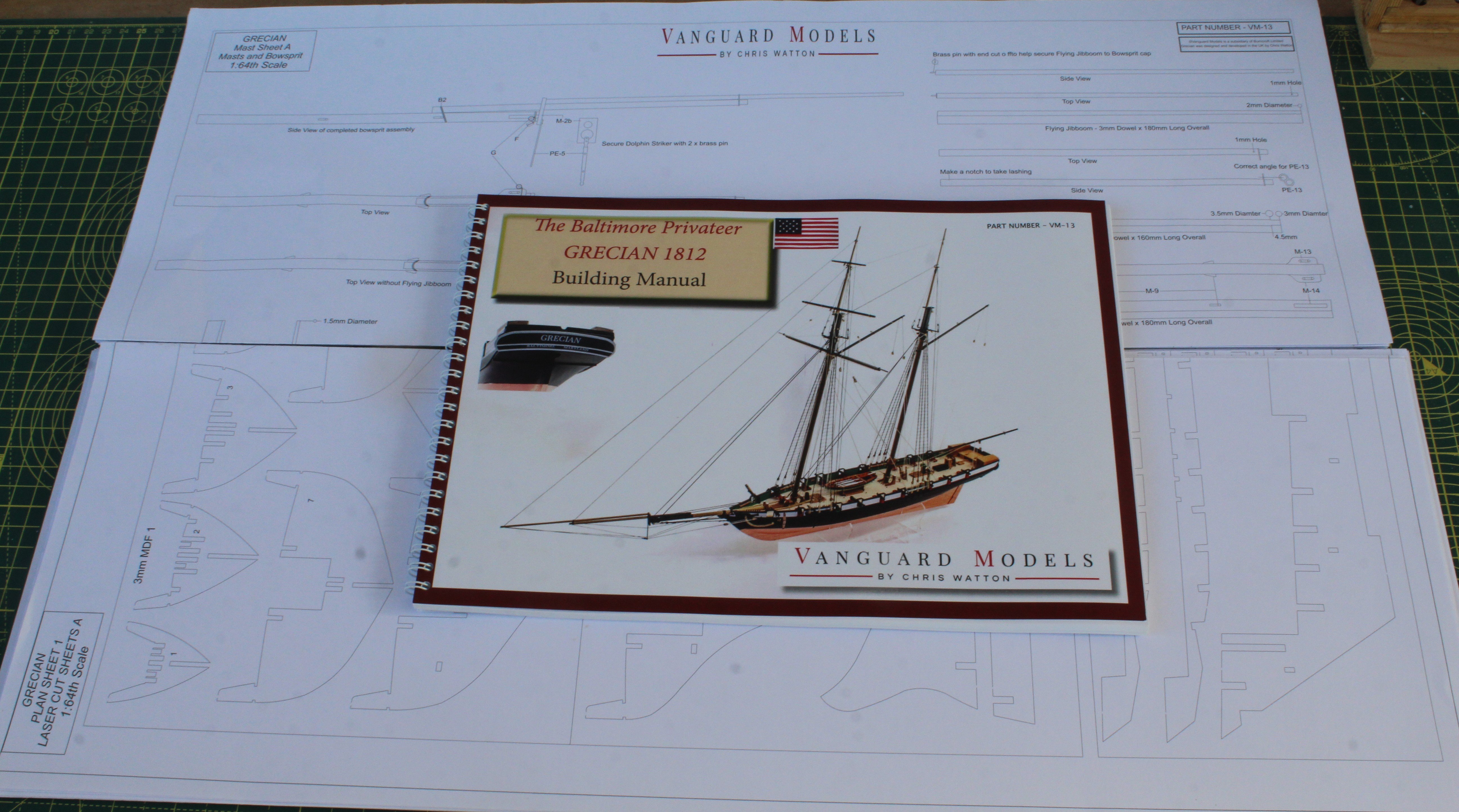
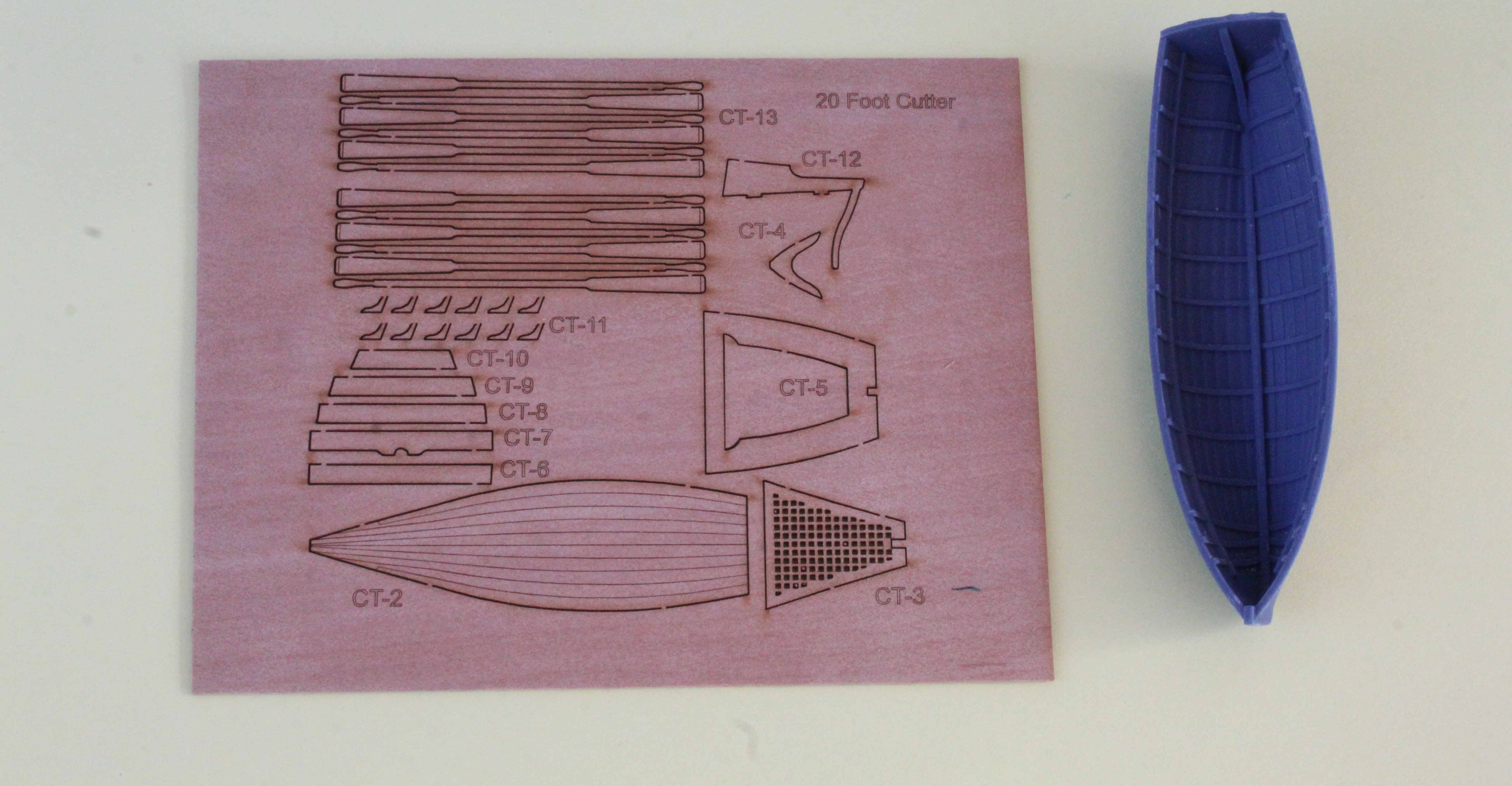
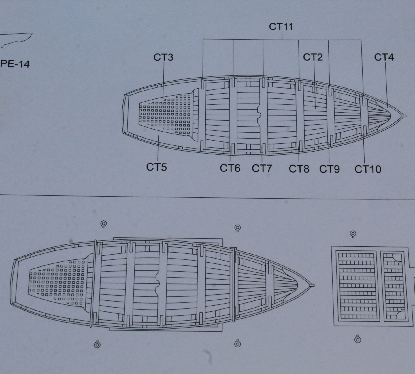
I am starting another Vanguard Models kit, this time I am going to build "The Baltimore Privateer Schooner Grecian". Grecian was an American schooner launched in 1812. During the War of 1812 she received a letter of marque. The Royal Navy captured her on 5 February 1814 and took her into service as HMS Grecian. I think this will be an interesting boat to build given the sleek lines of the hull. I am also thinking about trialing some different ideas during this build process such as trying out the 3D printed blocks and deadeyes from Syren. I am not sure about the green paint finish but I do like the way @ECK Grecian looks so it still a definite maybe. At the moment I am more inclined toward using the AK11817 RLM 65 (1938) Grey or the AK11180 Imperial Blue instead. The shipyard has had a good clean and tidy up and is ready now ready and waiting for me to start work on the Grecian. The kit finally arrived this afternoon. I thought I would start this project with building the 20 foot cutter. It seems to be a simple task. There is a 3d printed hull and a 1mm wooden sheet with all the fittings. Before painting the hull and fittings I thought it would it be a good idea to test fit the fittings. The floor and rear floor both seem to be a good fit. The bow knee and/or hull will need a bit of fettling as the 3D printed bulkheads appears to be preventing the bow knee from sitting on the ledge. (Post Amendment The knee is located at the top and not on the ledge) I have similar issue with fitting the stern sheet (rear seat). The various thwart seats seemed to be a good fit however the thwart / seat knee will require a slight adjustment.


-
Thanks Maurice. She has now been put on display in our living room.
-
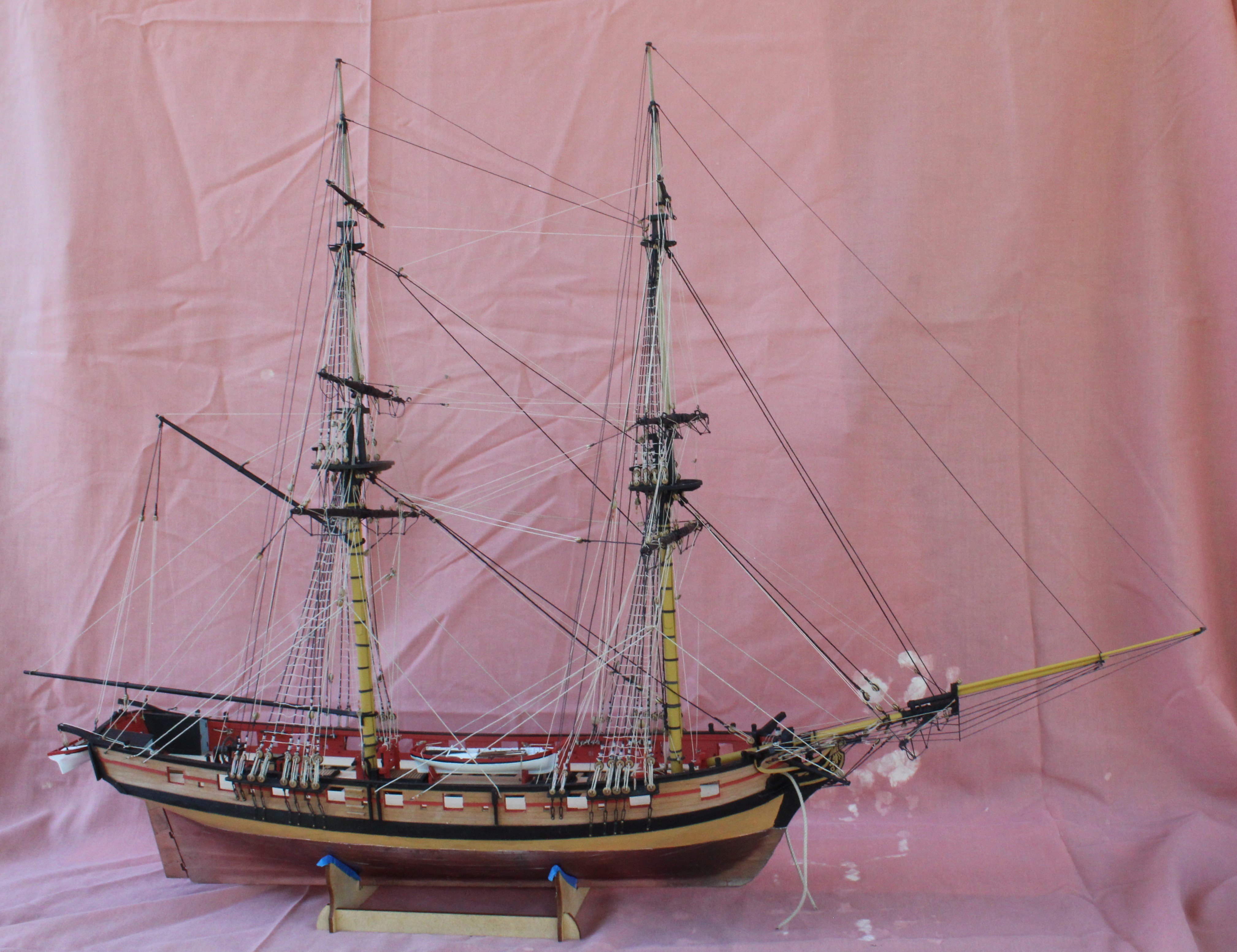
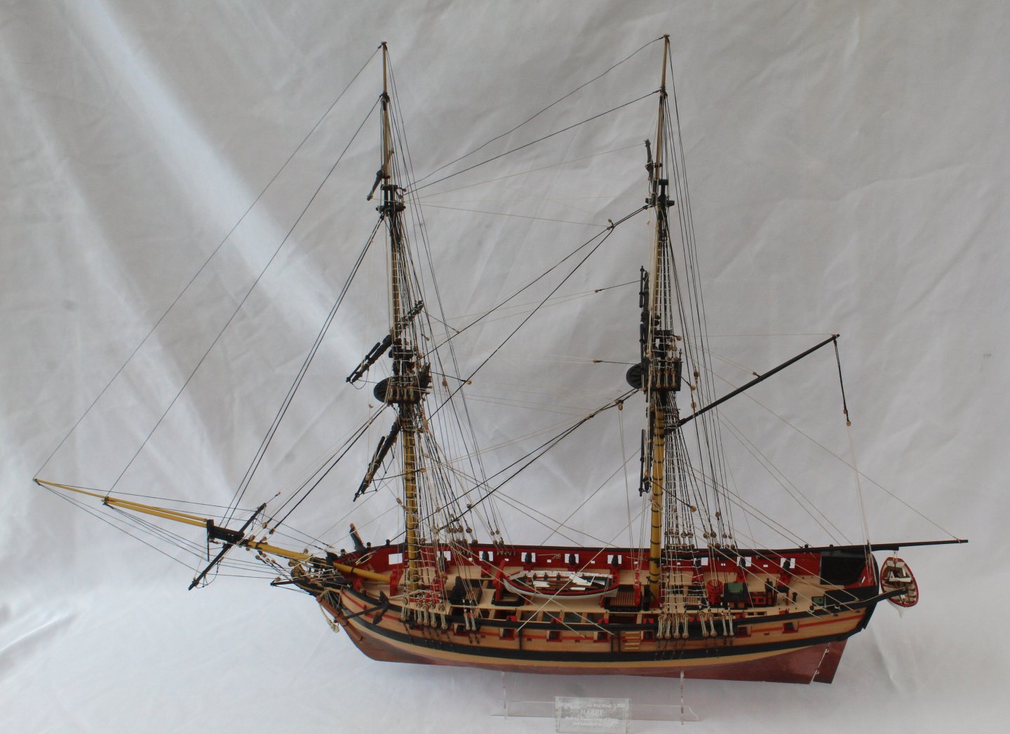
I have now completed all the the work on my Harpy build. This has been one of my most enjoyable builds. I have made a few mistakes during the build and rigging process but overall I am very happy with how the finished model looks. @chris watton continues to set a very high bar with the standard of his kits and I am looking forward to starting my next project which will be The Baltimore Privateer Schooner Grecian. Many thanks to everyone who has viewed my build log and for the likes and comments.


- 241 replies
-
- 16
-

-

-
- Vanguarrd Models
- Harpy
- (and 1 more)
-
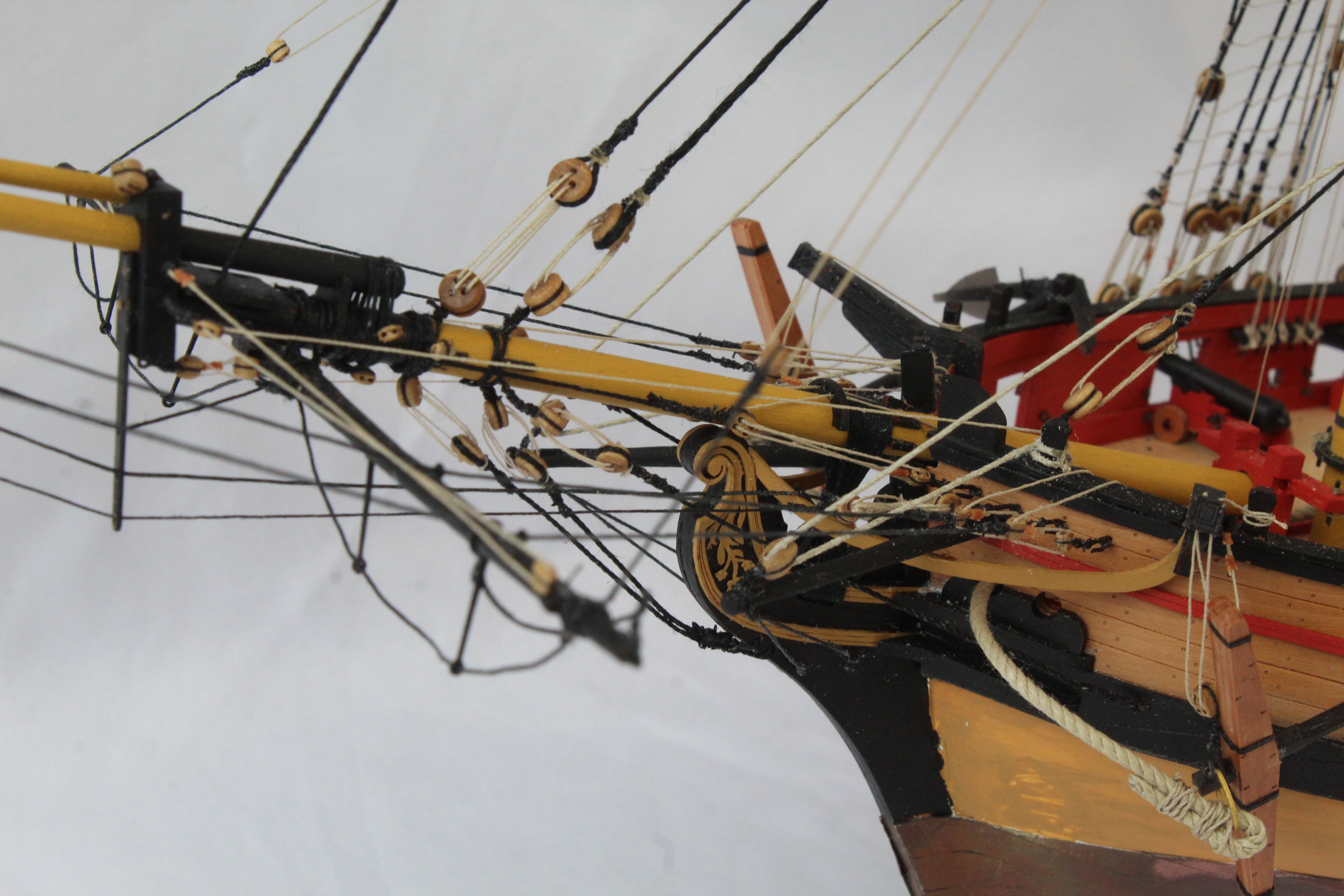
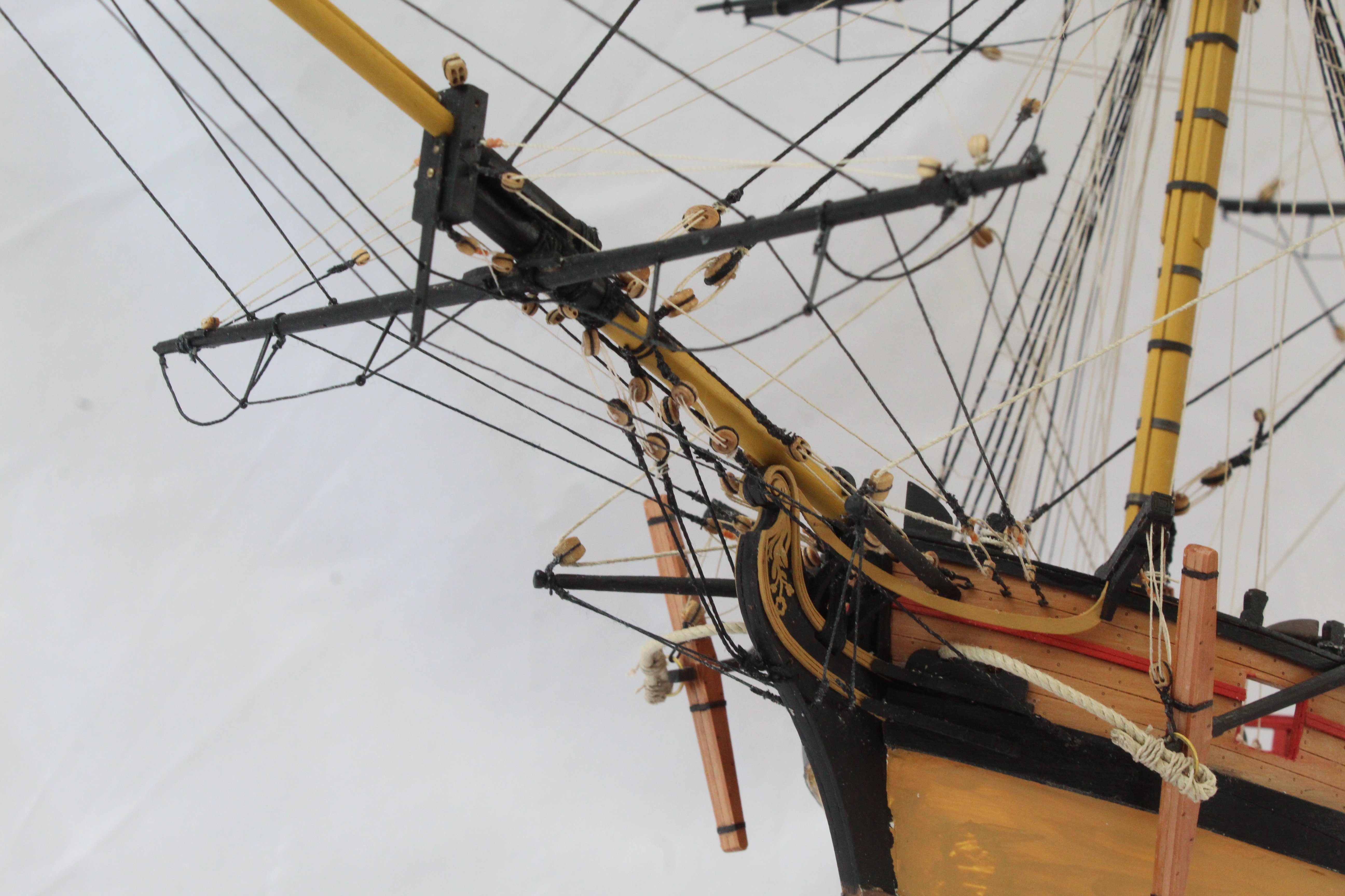
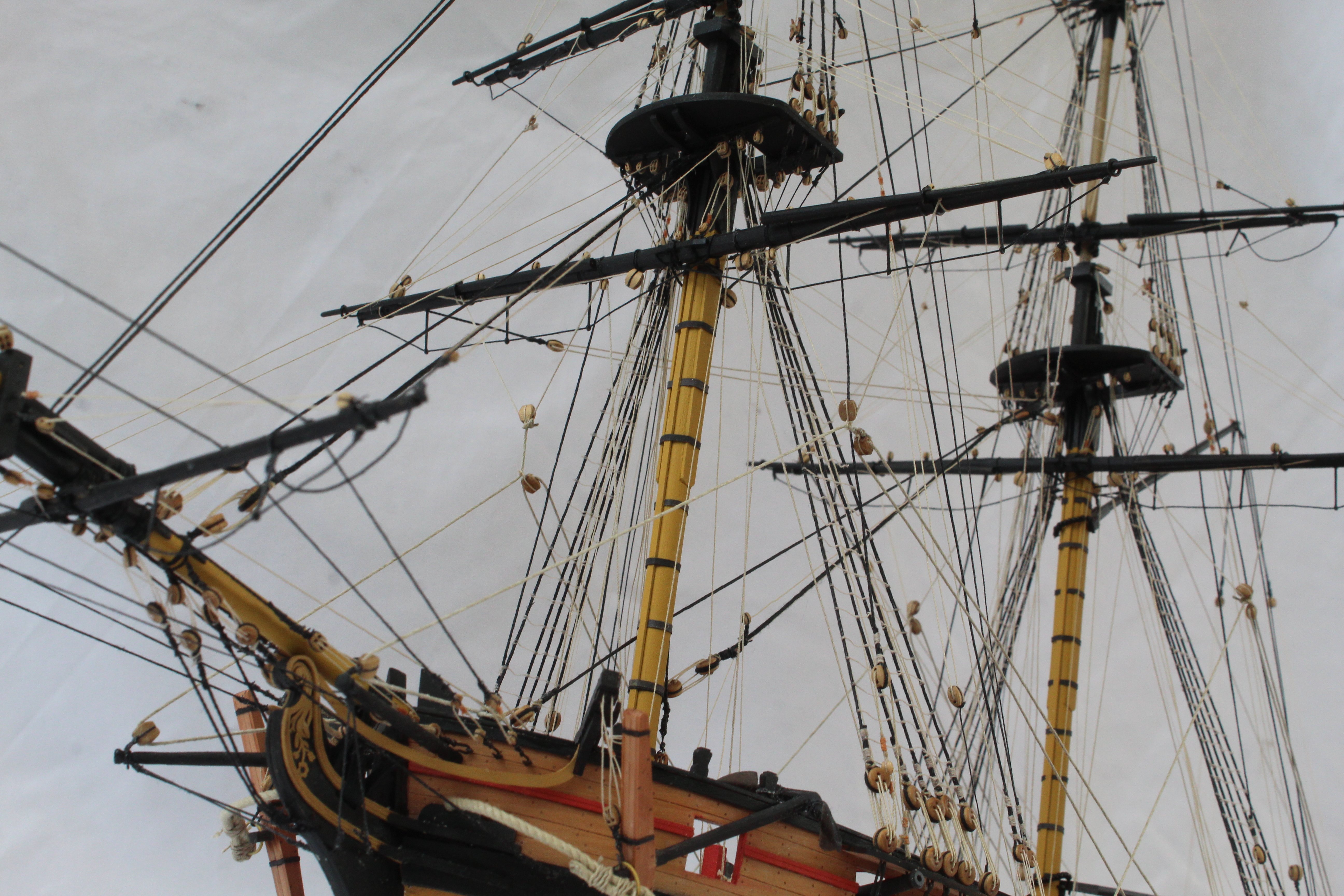
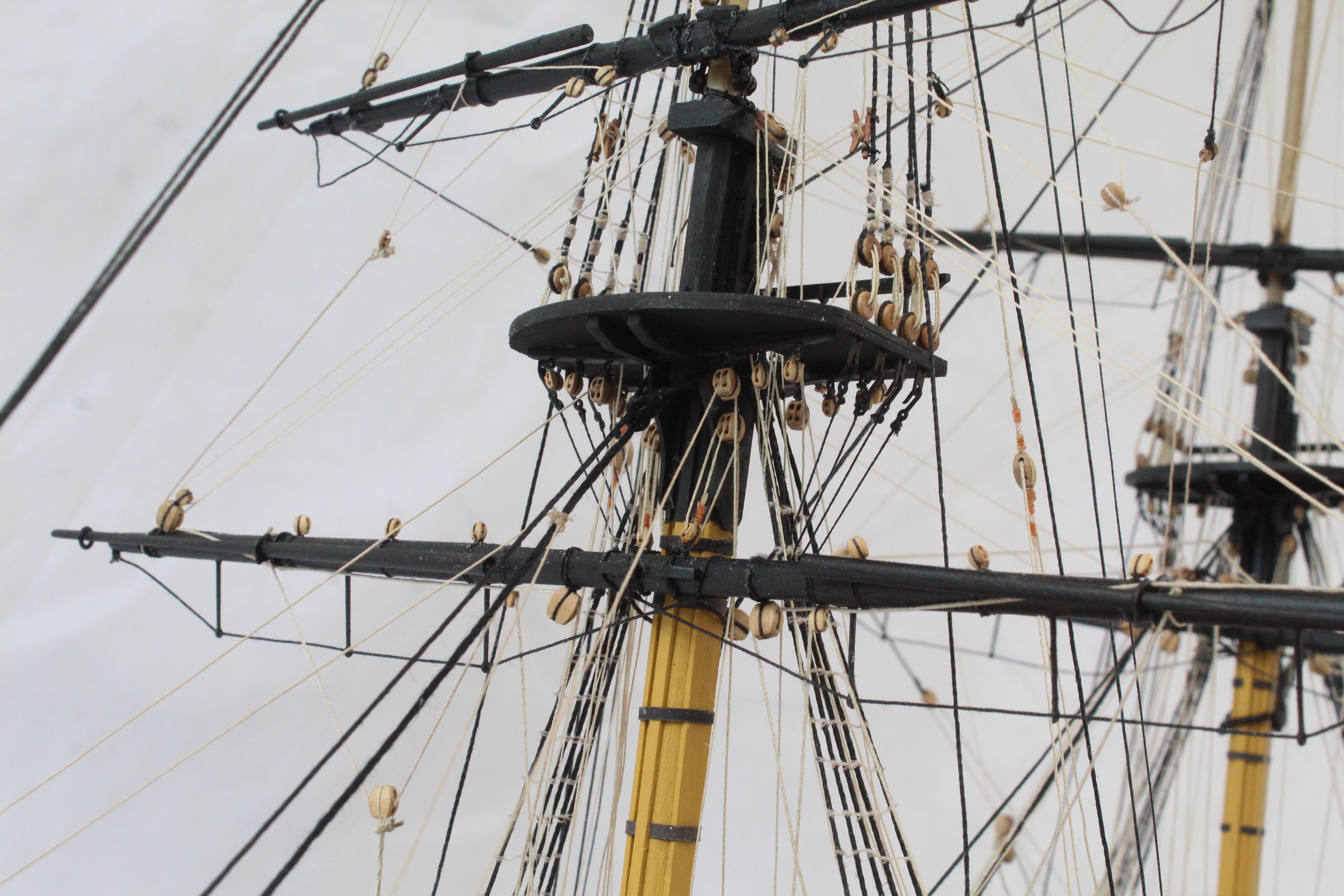
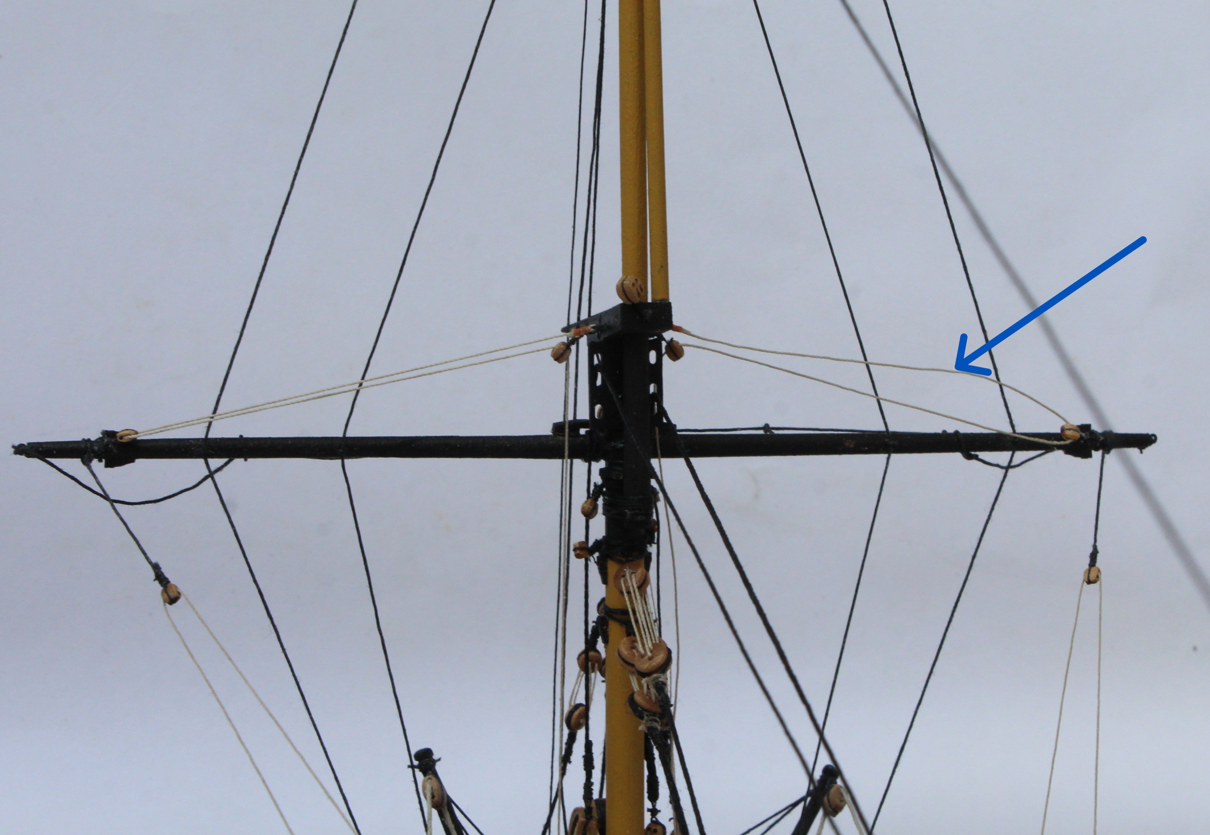
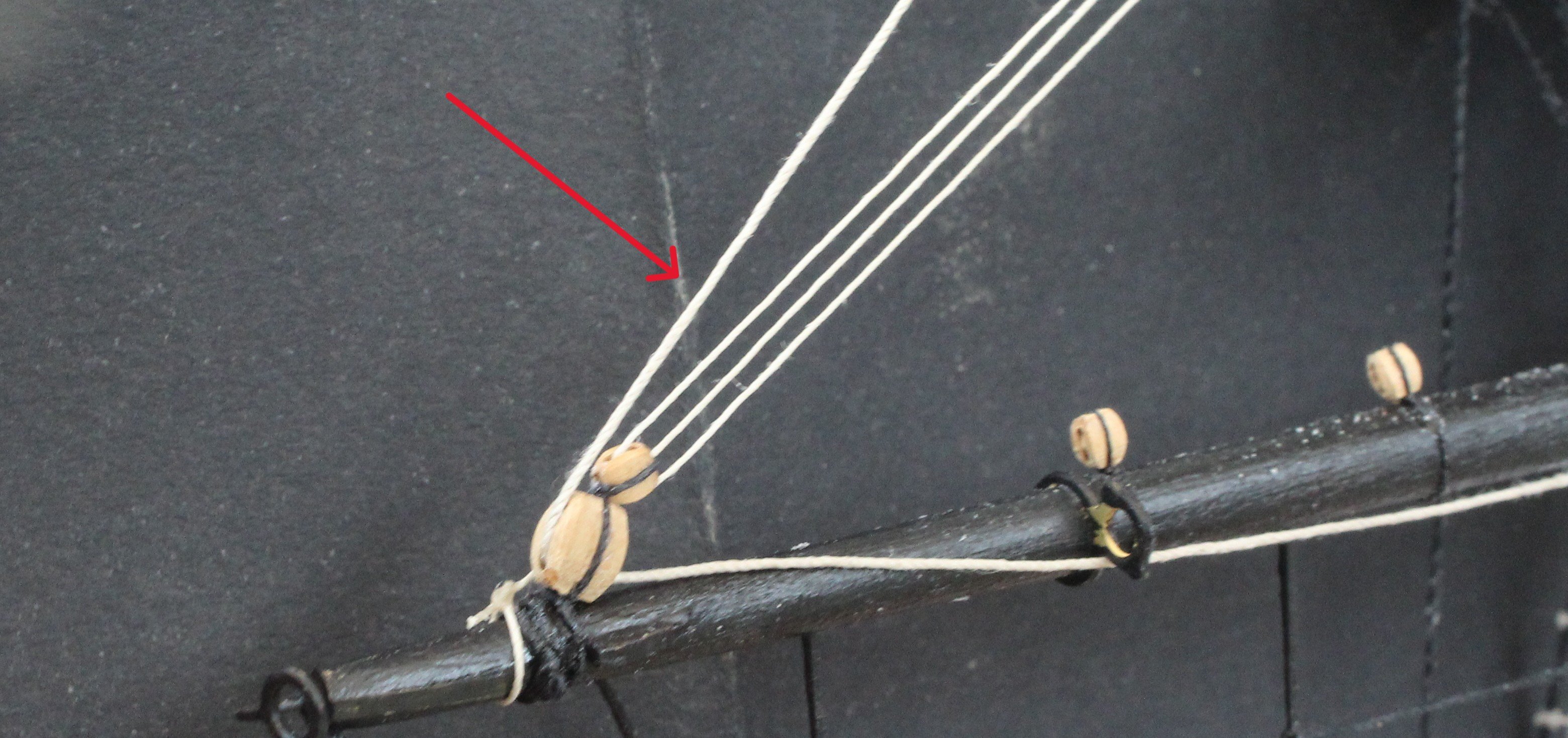
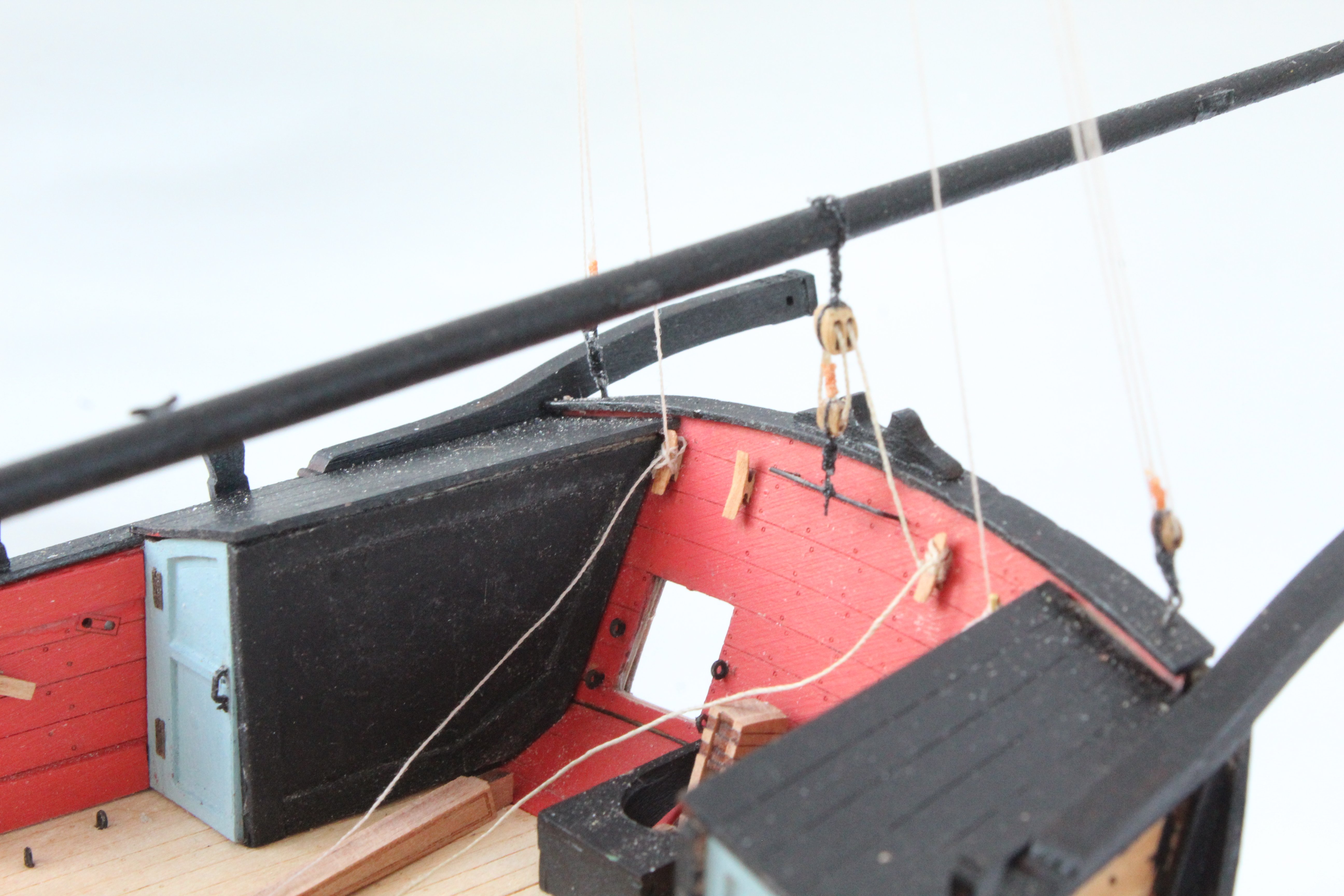
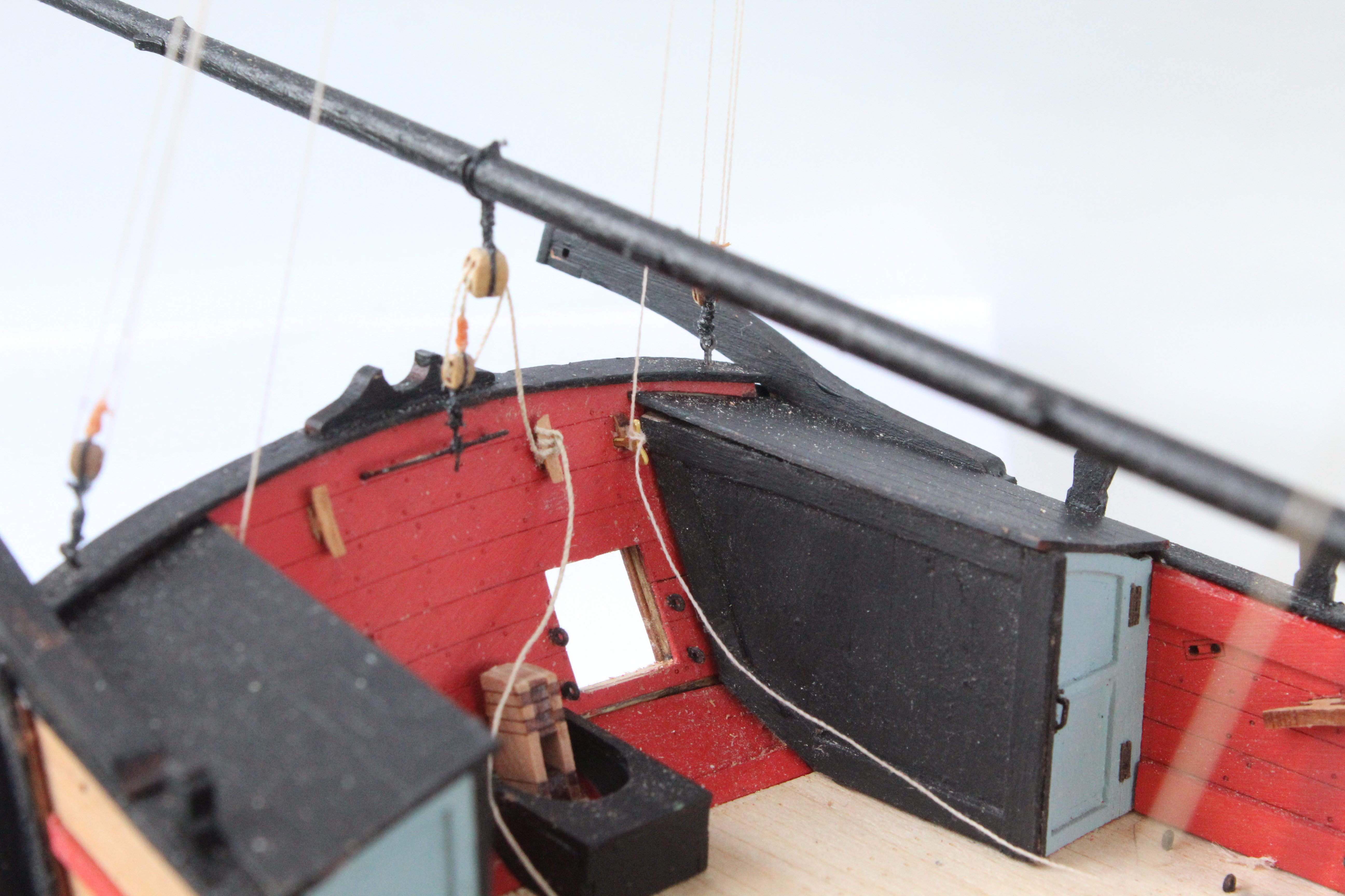
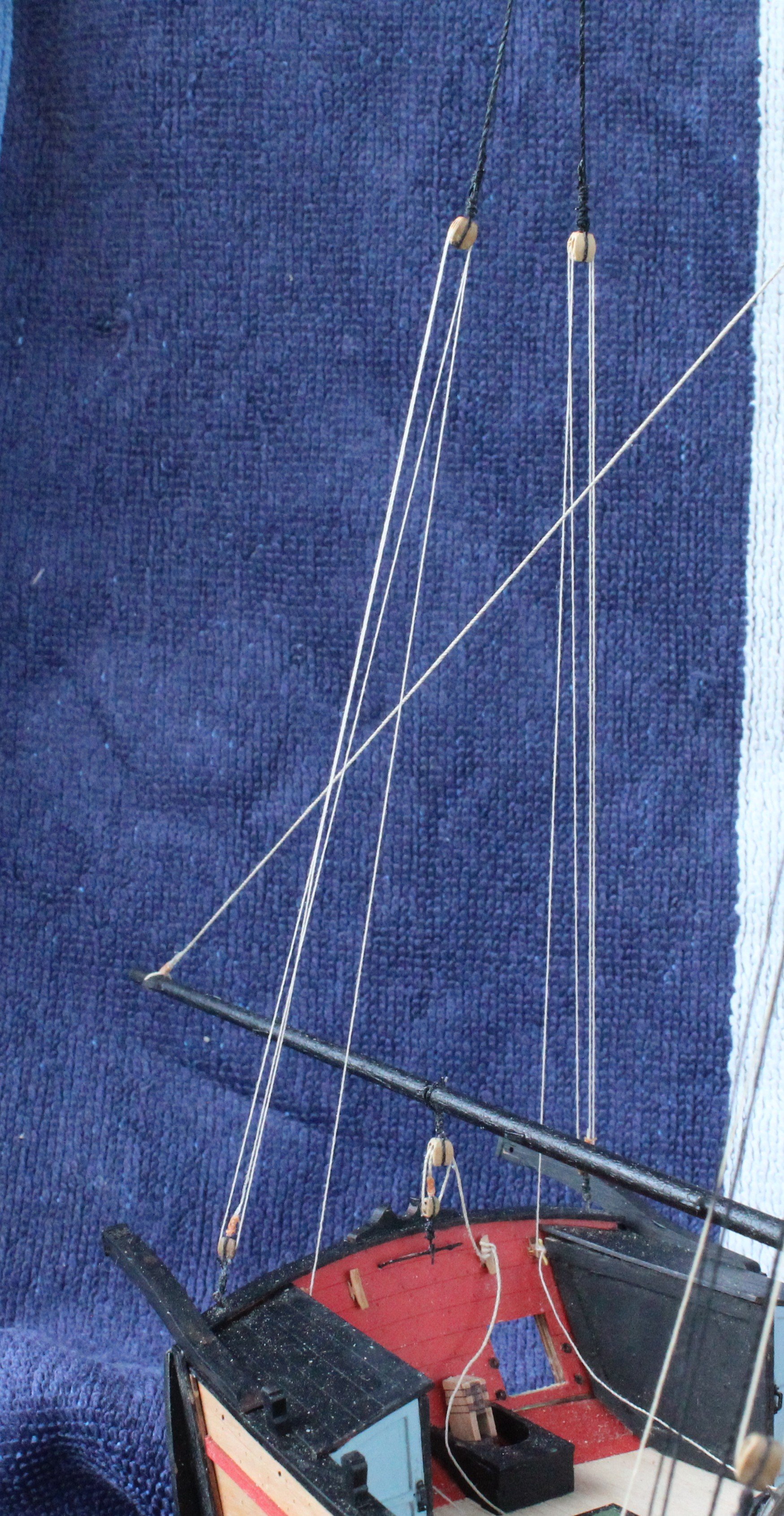
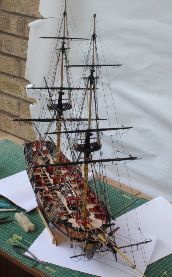
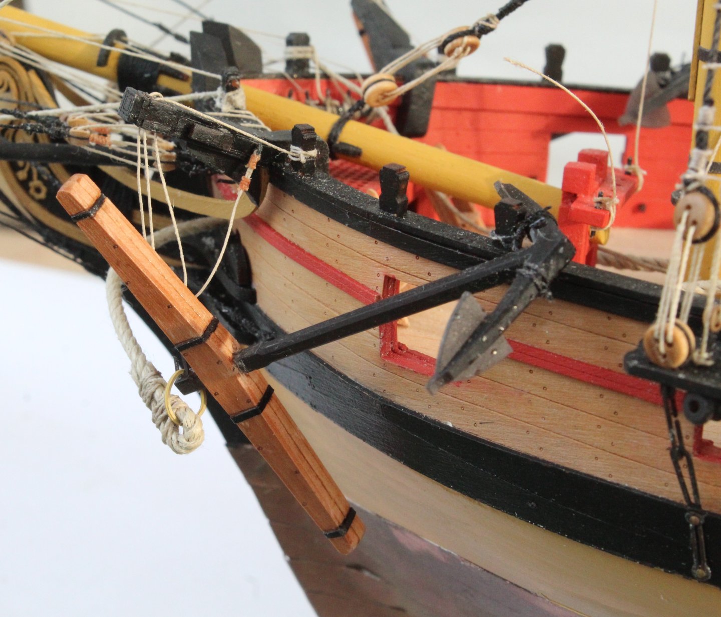
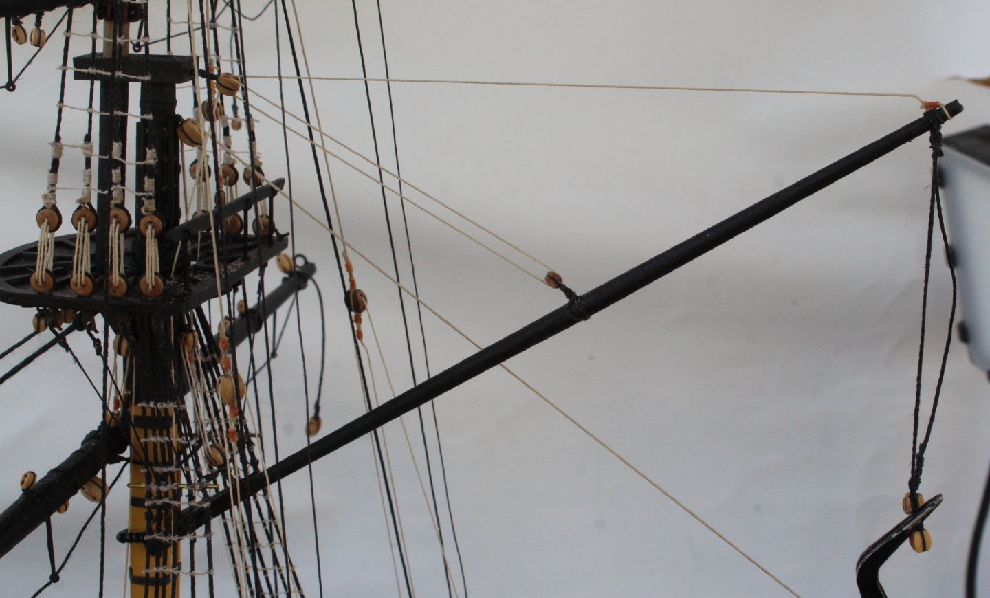
Not much more left to do. This morning I have redone the spritsail yard braces so the spritsail yard is now set square with relation to the bowsprit. As a result I will have to tighten up one of the lifts, as can be seen in the photo below. I did end redoing the starboard side anchor rigging with the double block properly rigged. All the stunsail booms have been added. There is still a little bit more of tiding up to do and to make the perspex stand. To complete this, hopefully, penultimate build log post I have added photo of the Harpy on the workbench.


- 241 replies
-
- 7
-
-
- Vanguarrd Models
- Harpy
- (and 1 more)
-
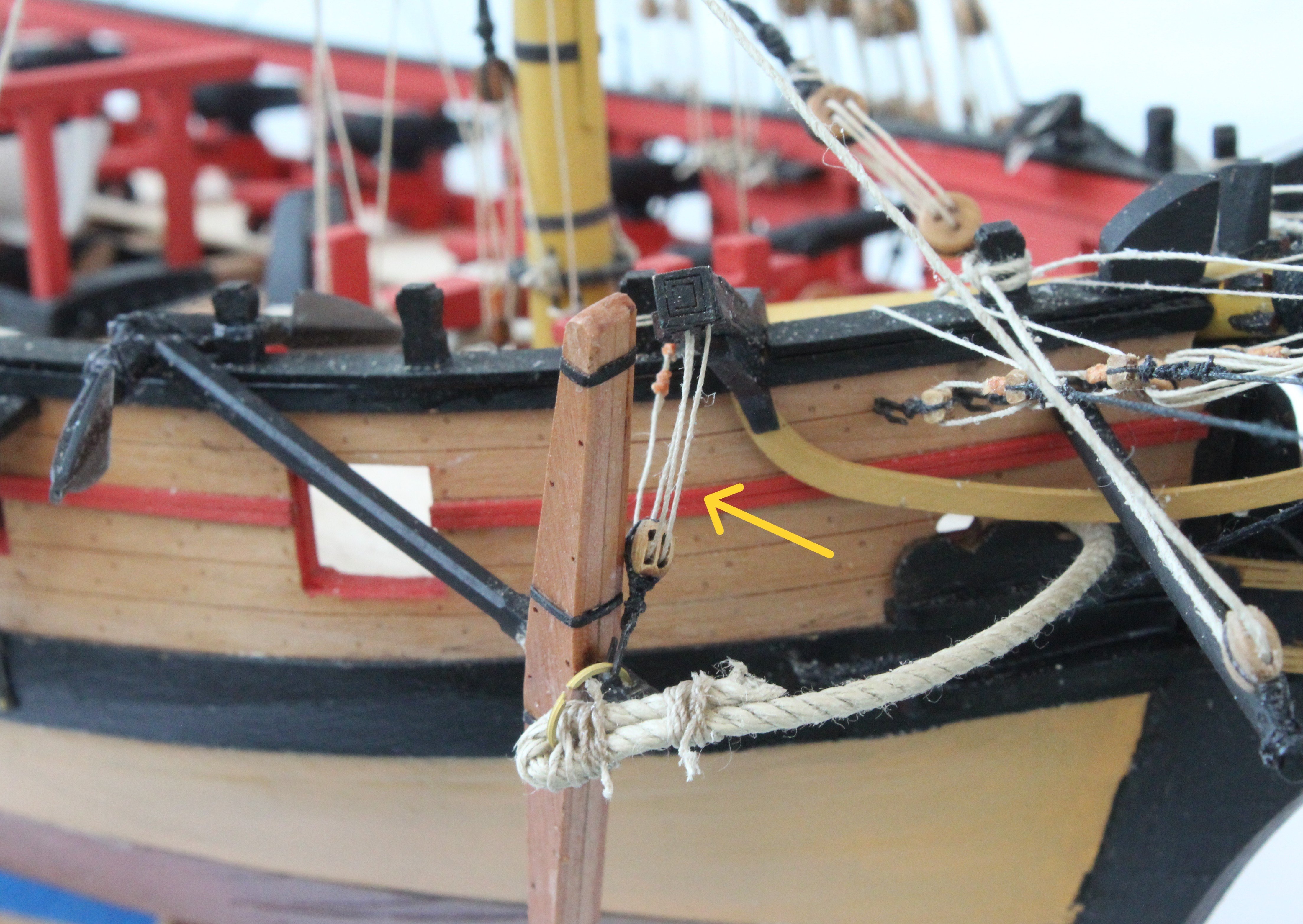
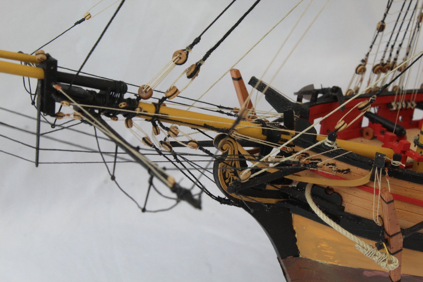
Just a quick update. The port side anchor as now been rigged, and this time I did reeve the thread through the double block correctly, as can be seen in the photos below. The end is now very much in sight for this build.

- 241 replies
-
- 4
-
-
- Vanguarrd Models
- Harpy
- (and 1 more)
-
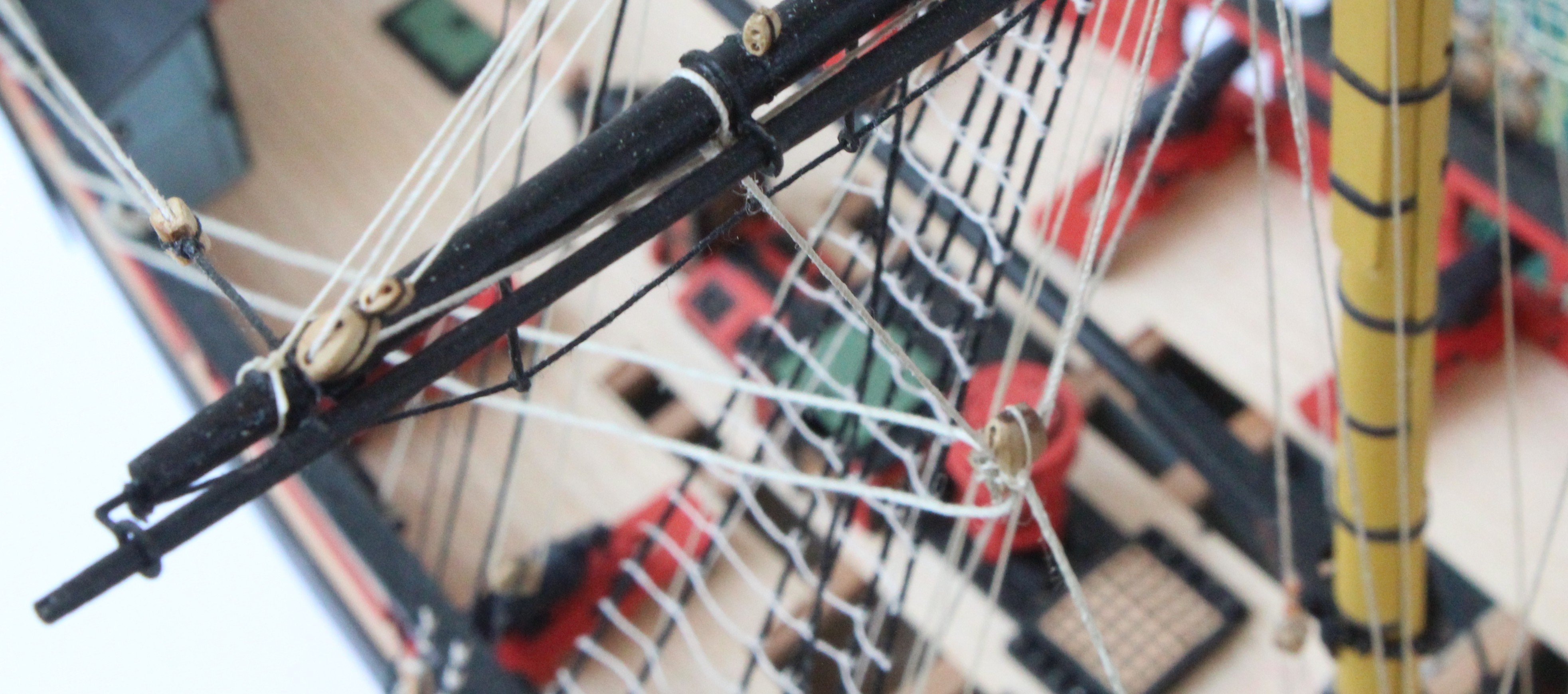
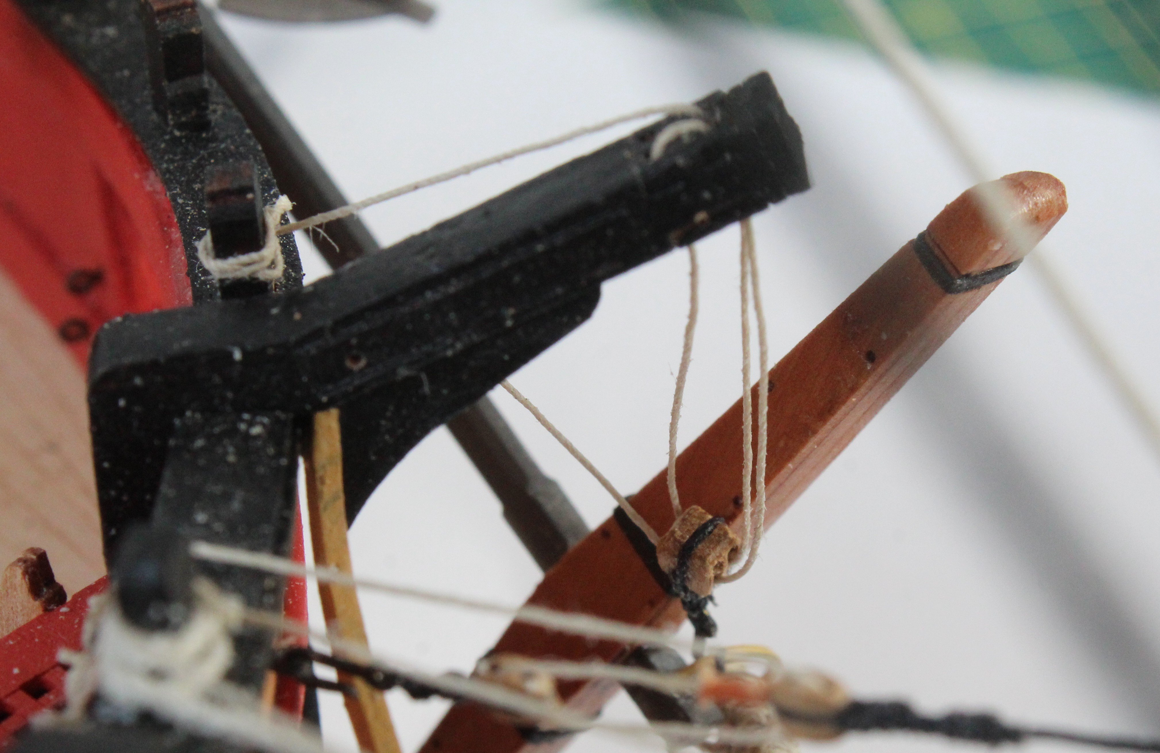
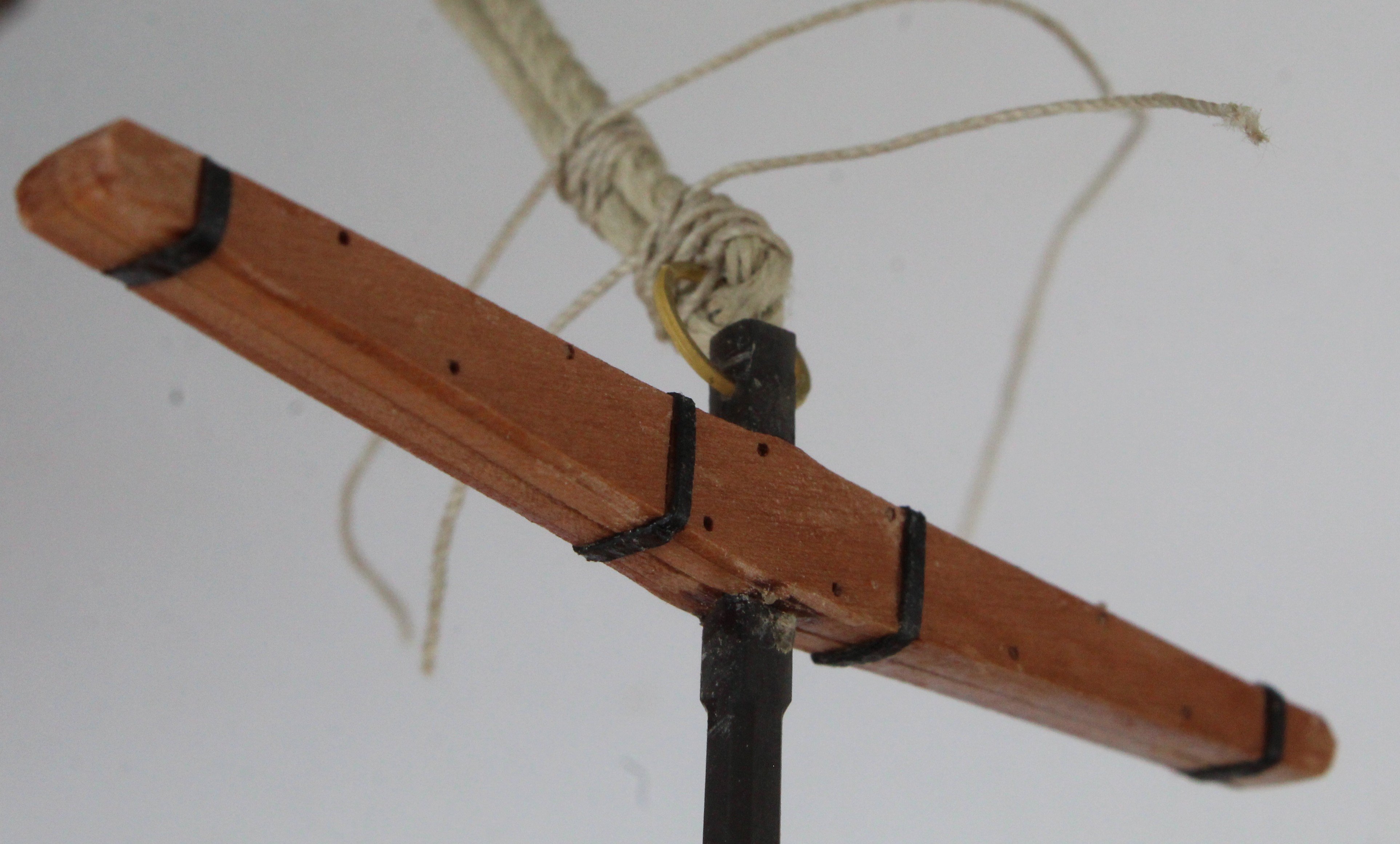
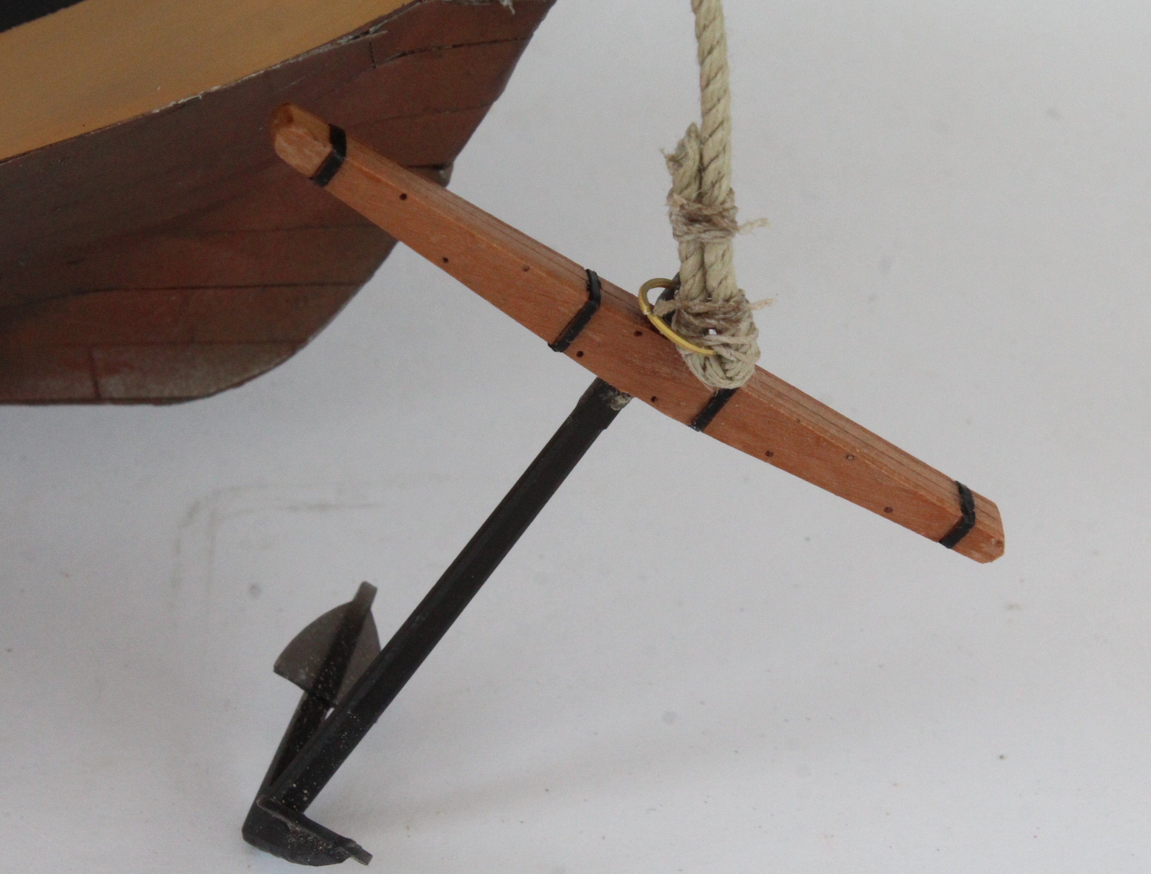
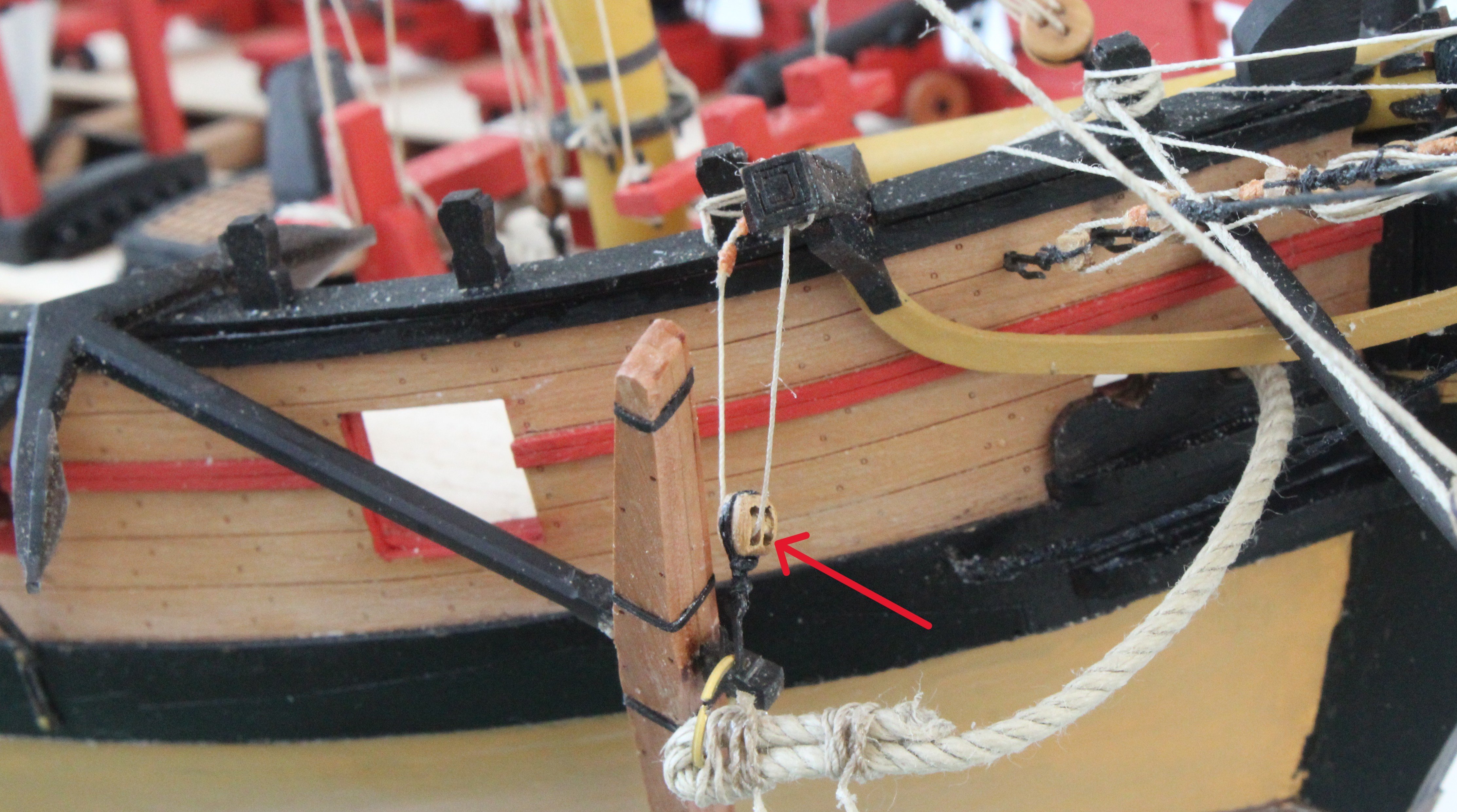
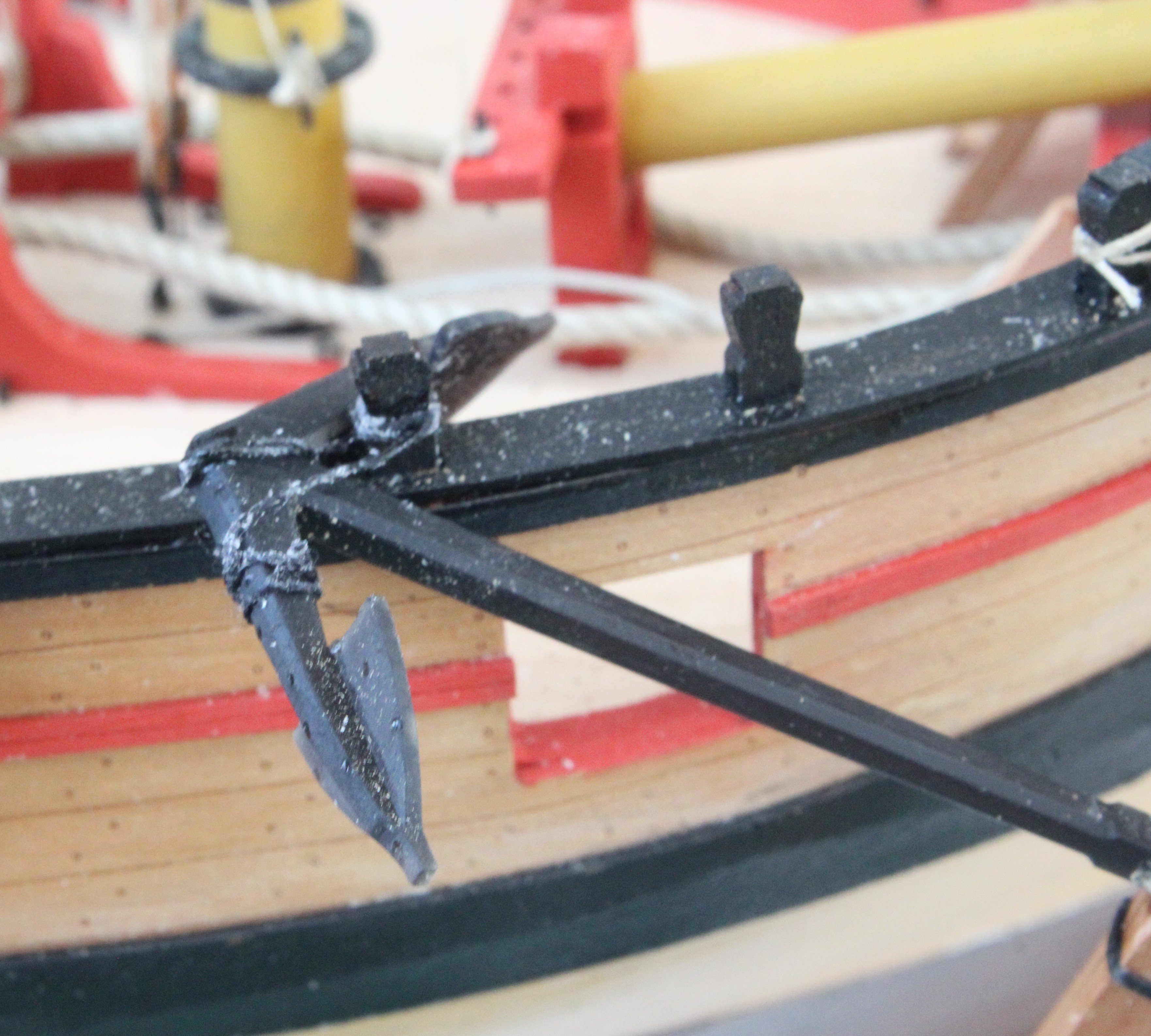
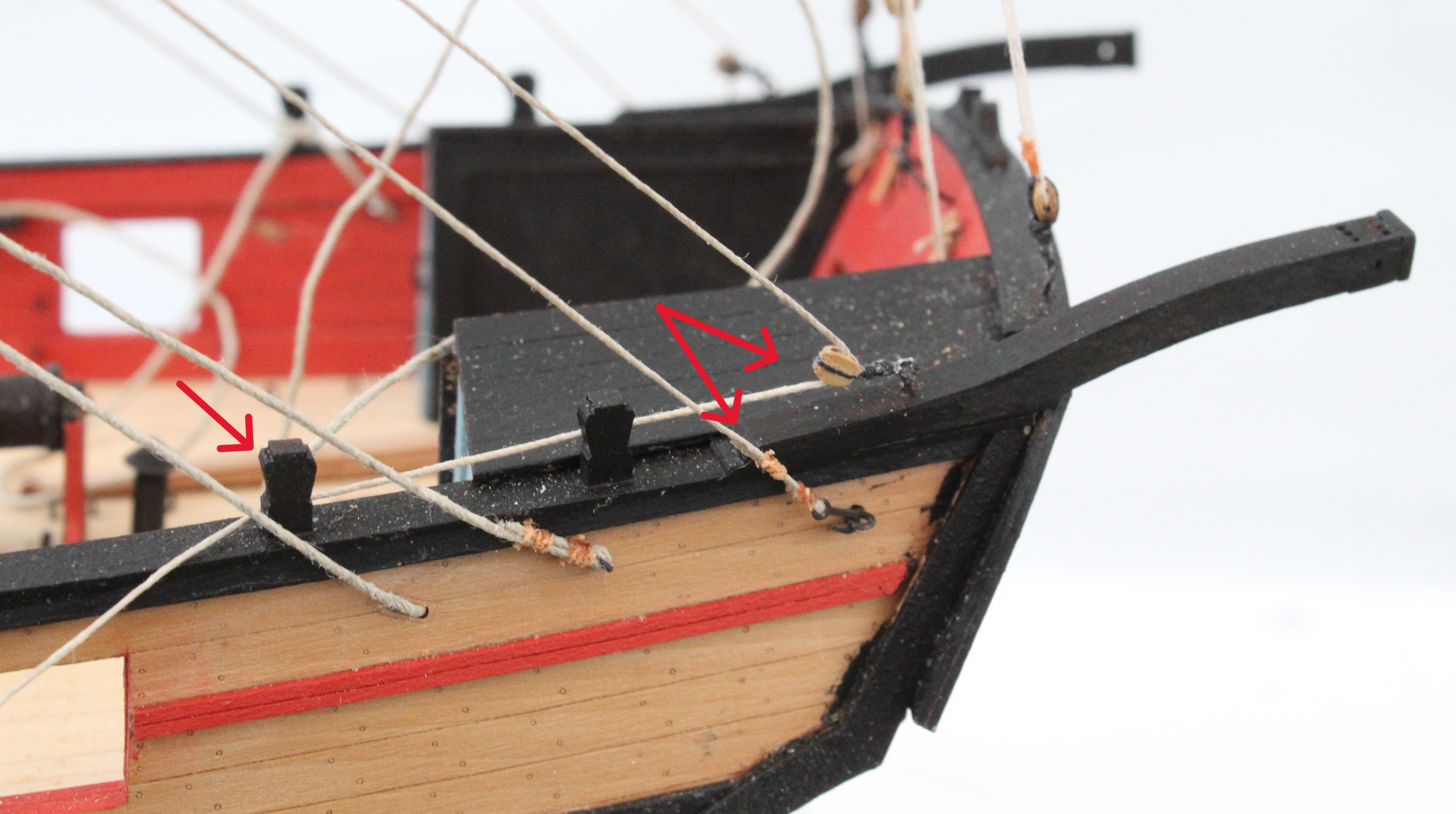
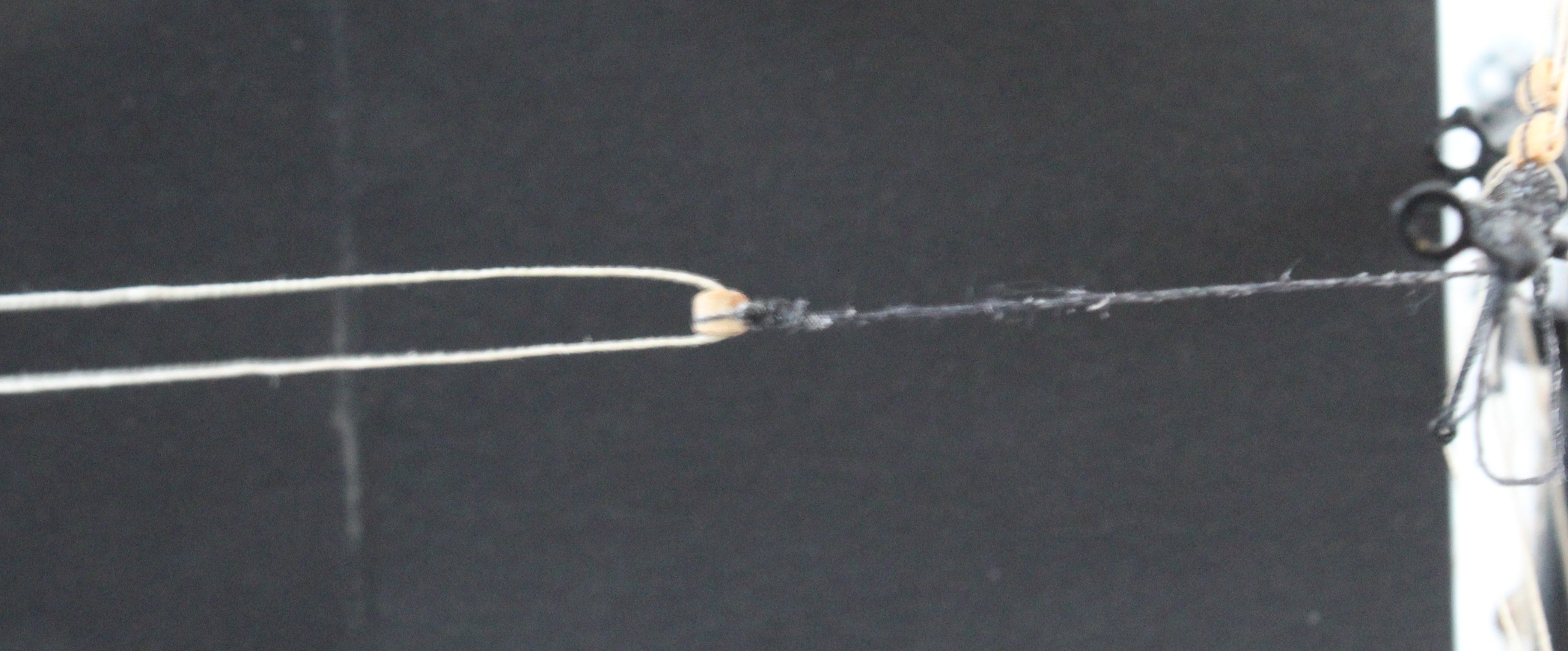
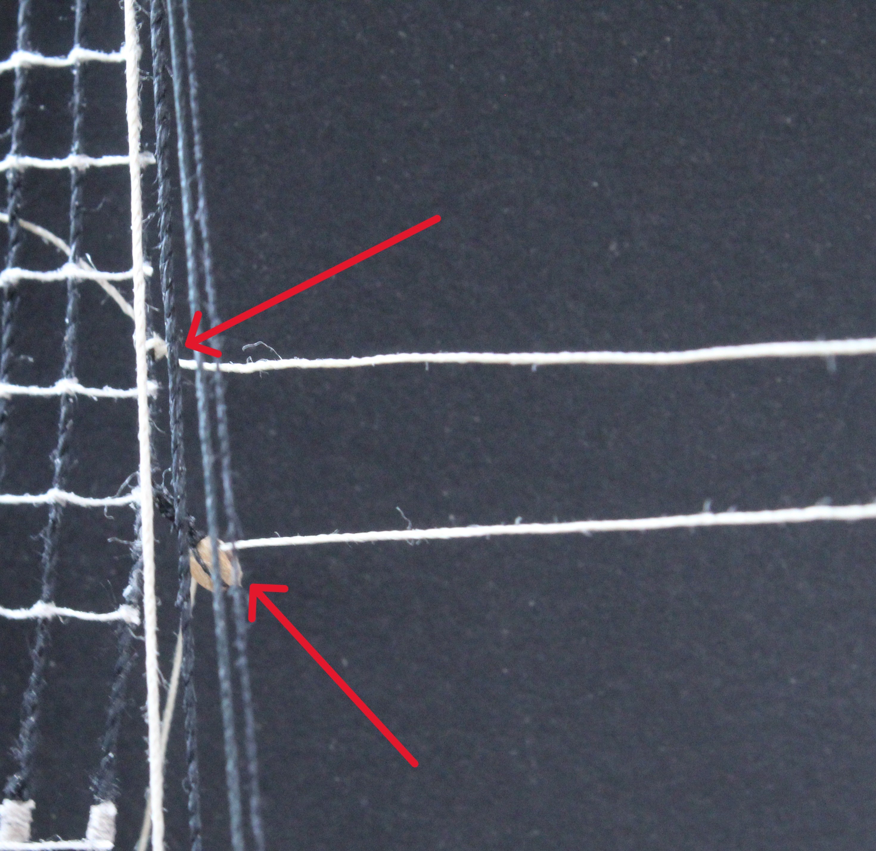
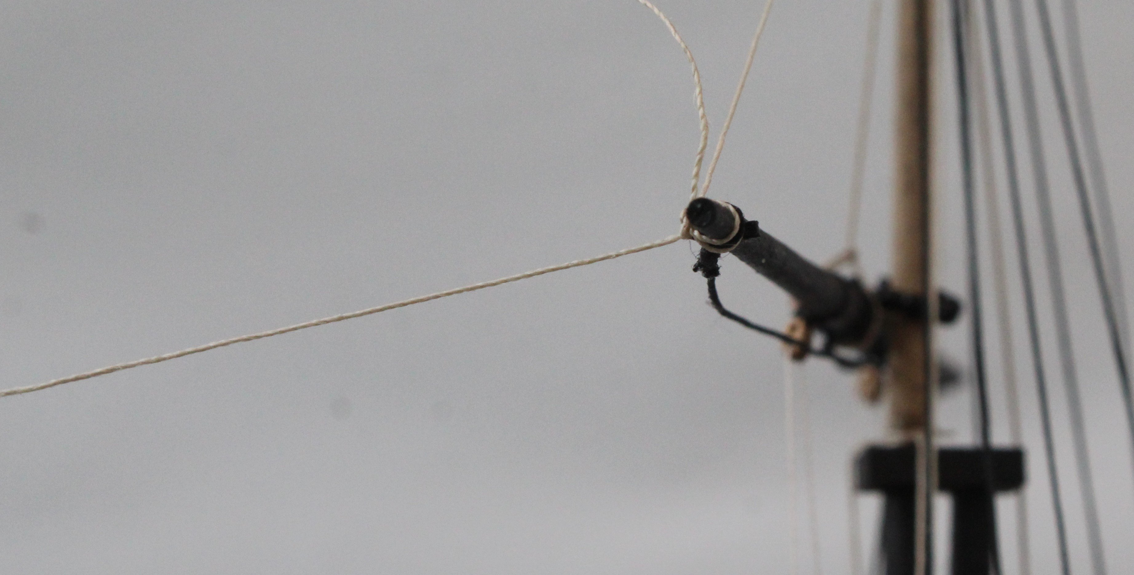
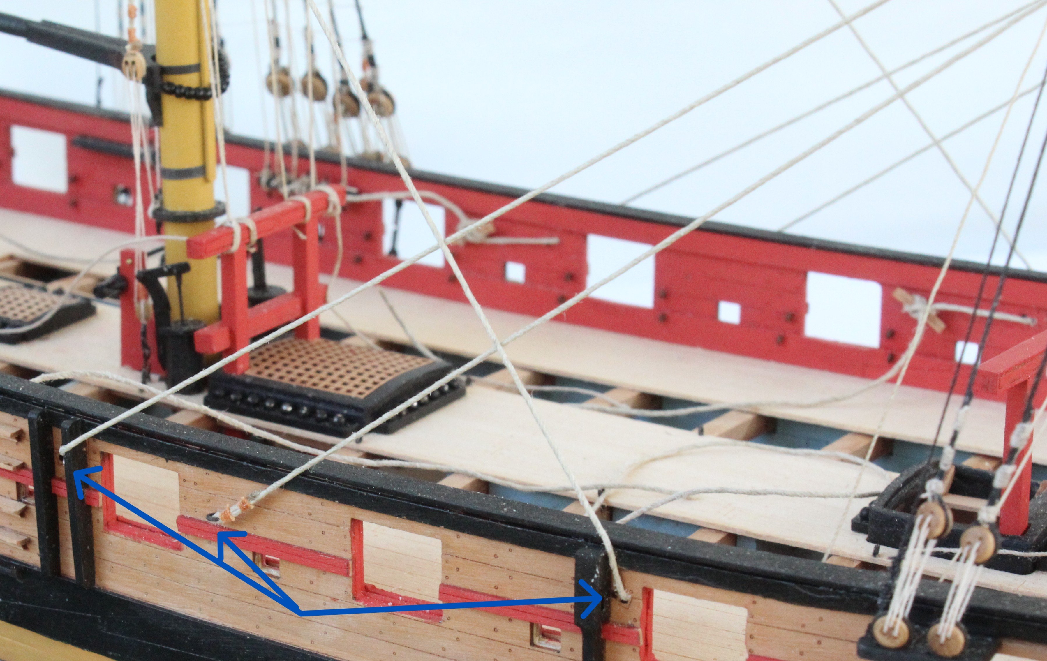
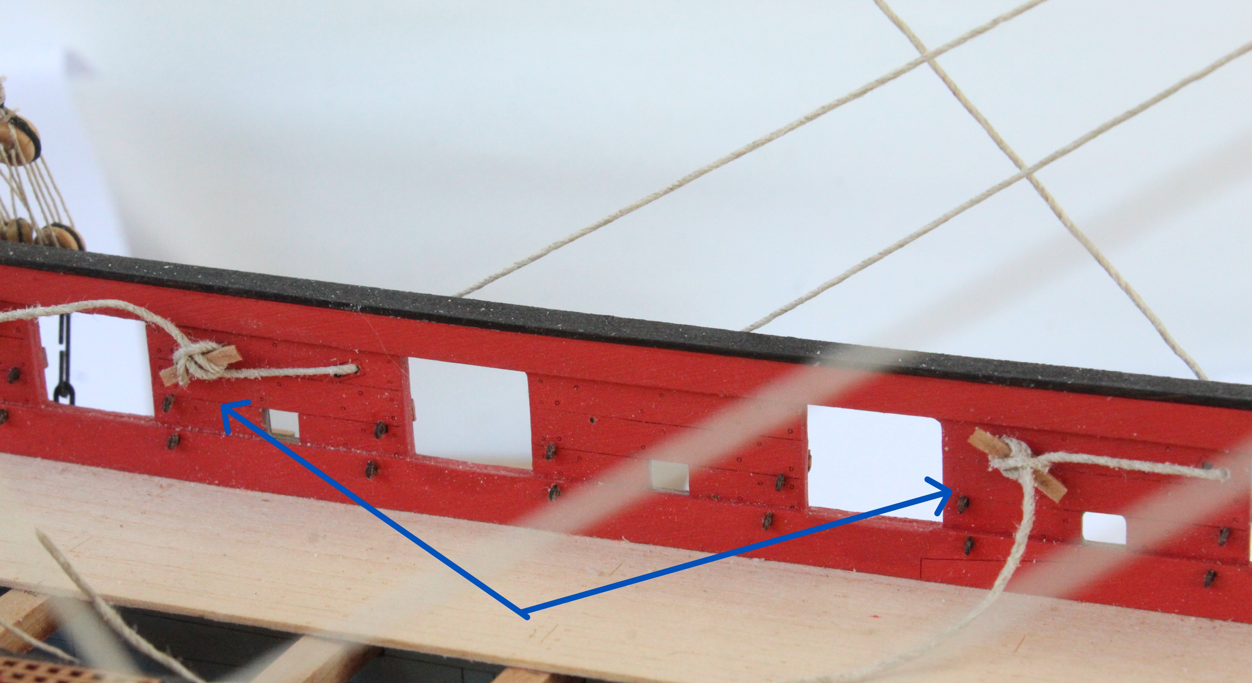
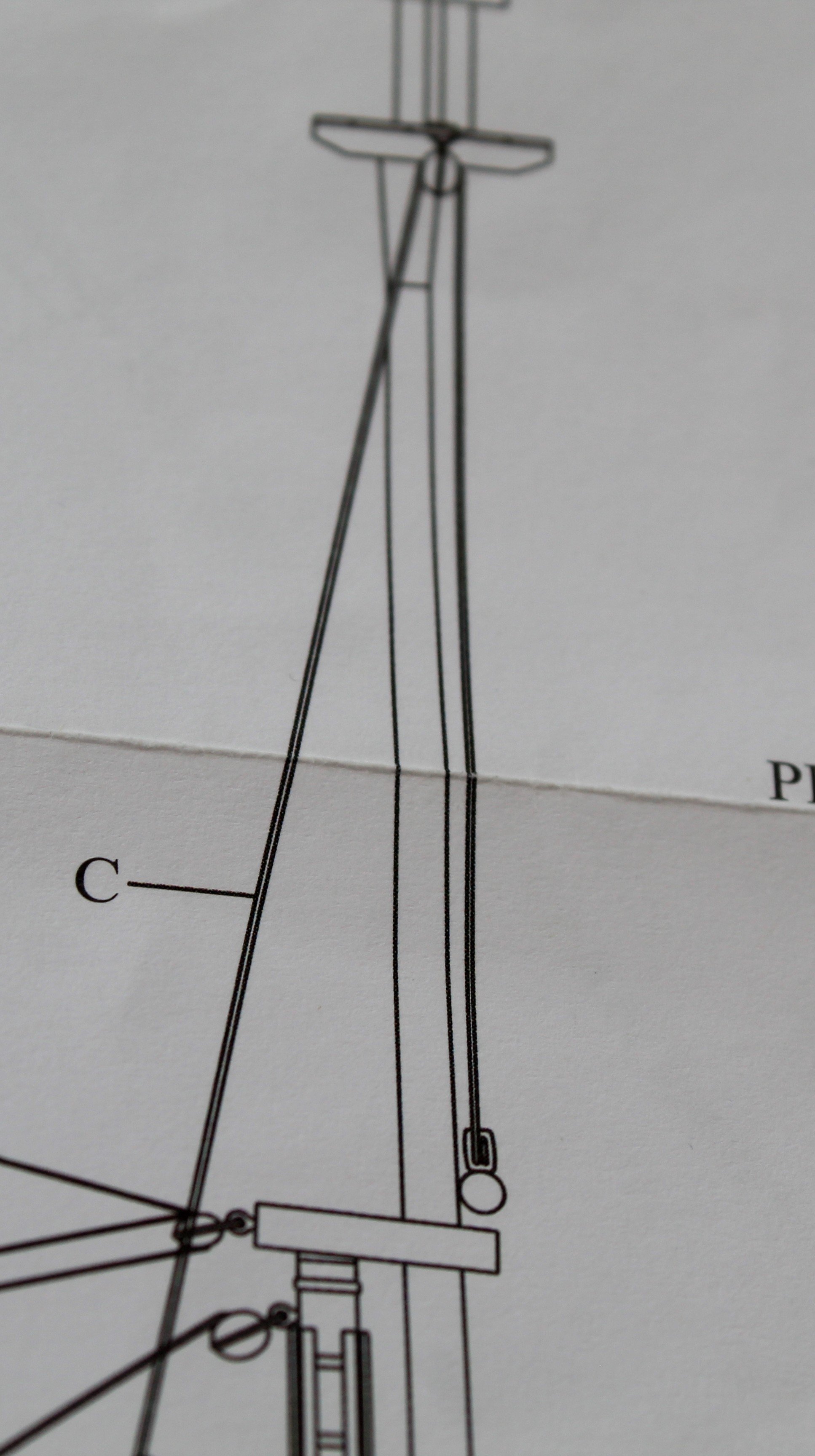
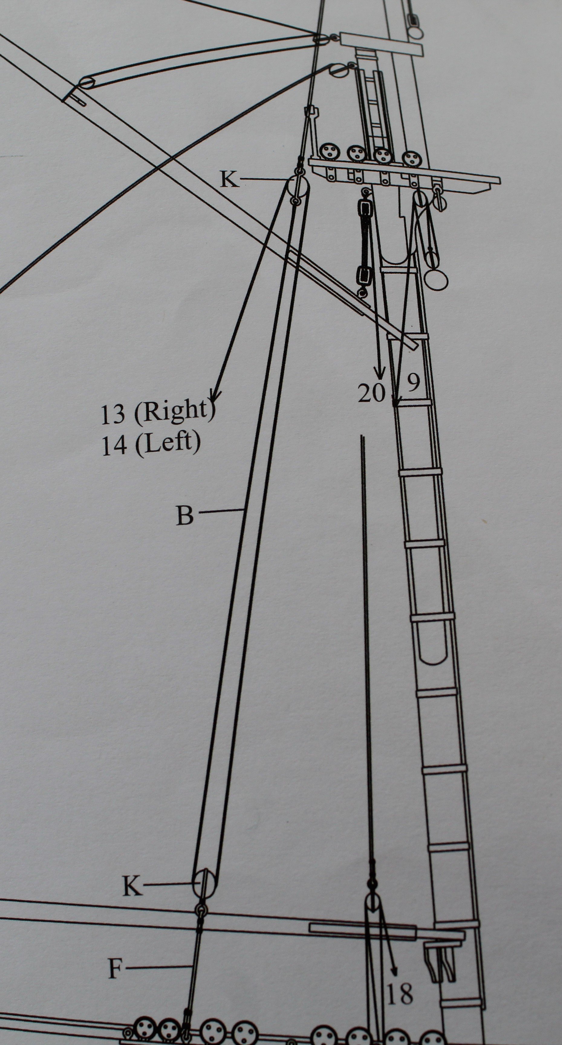
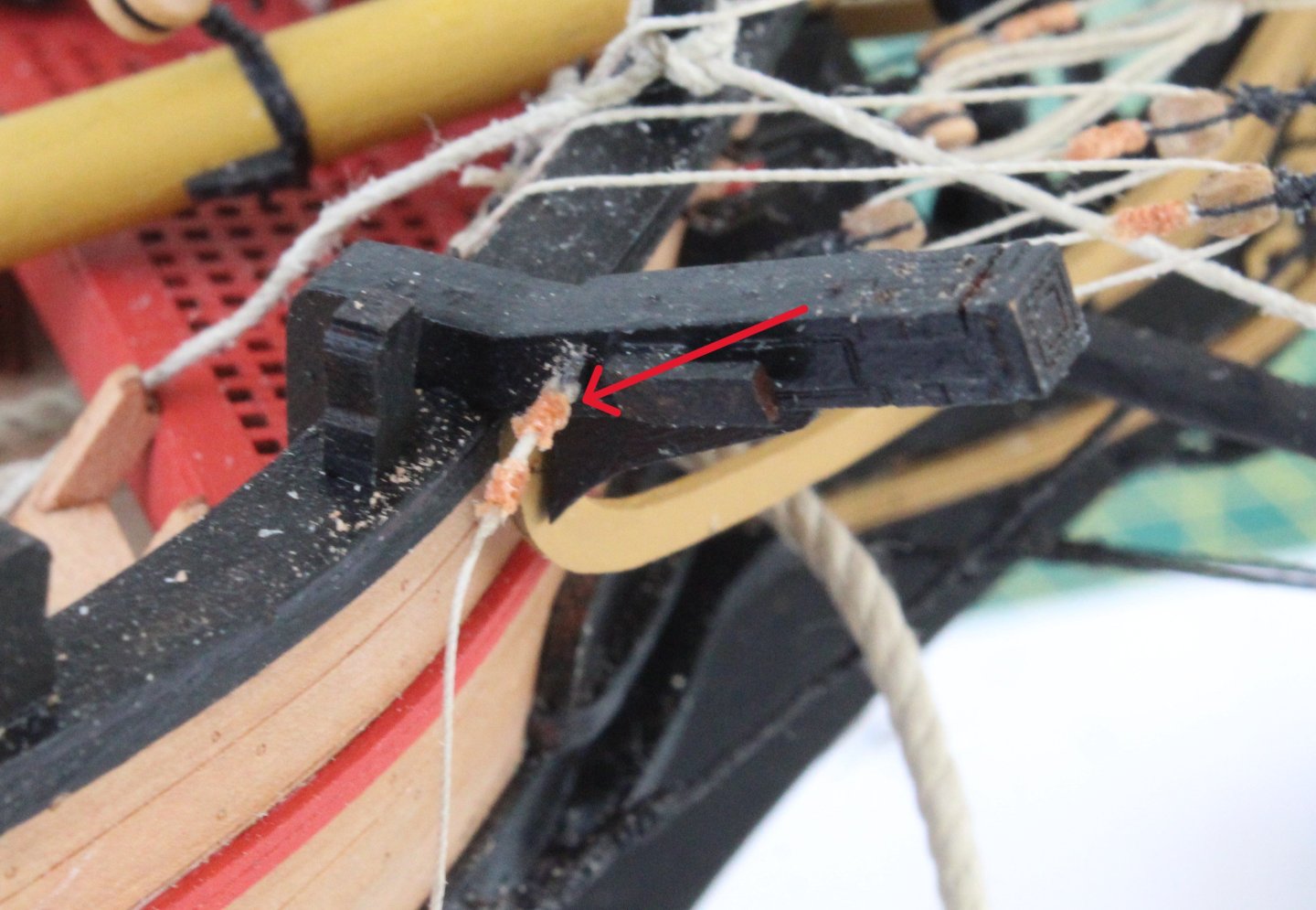
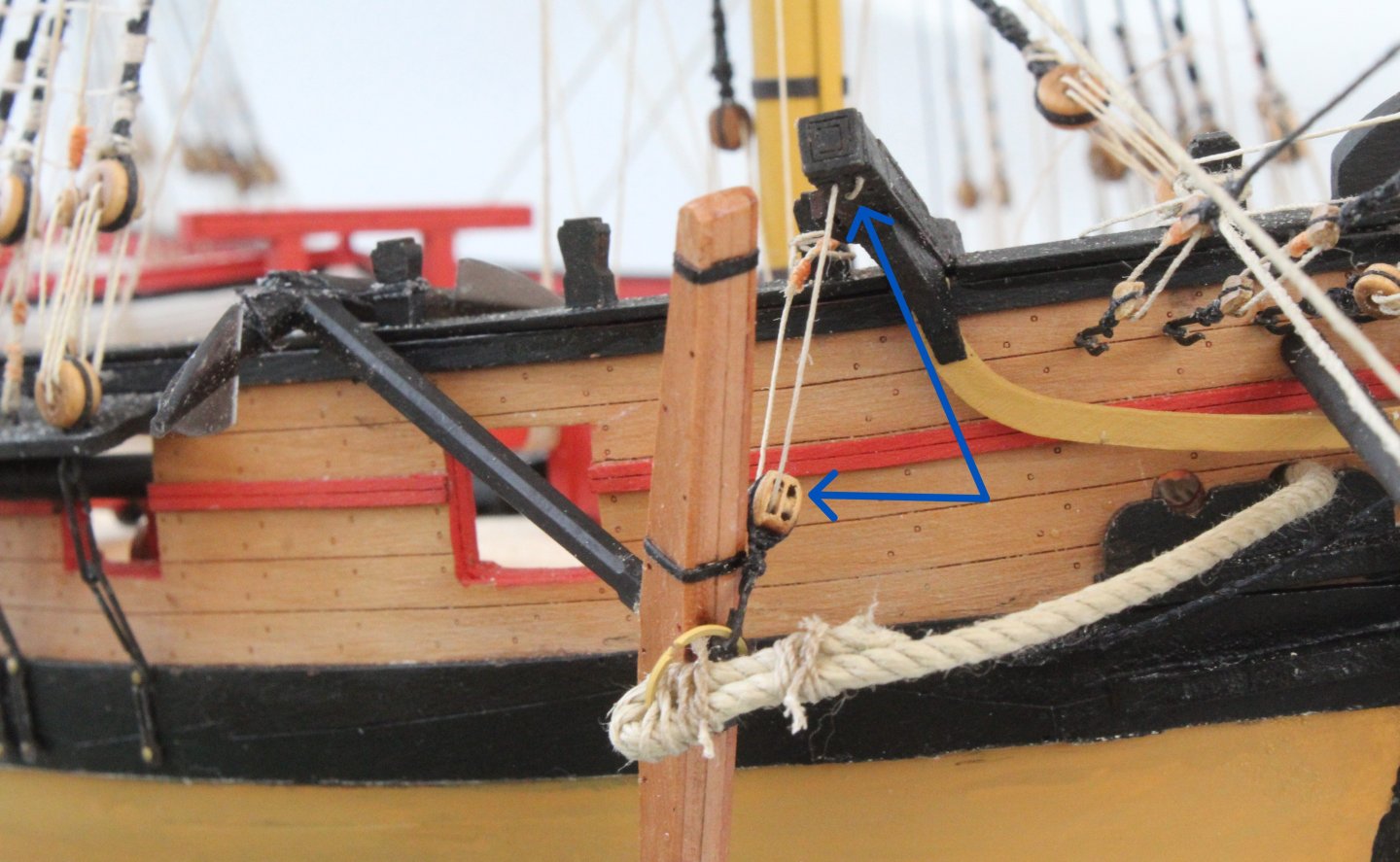
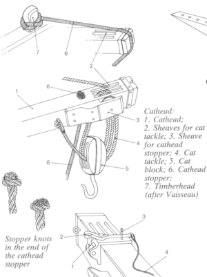
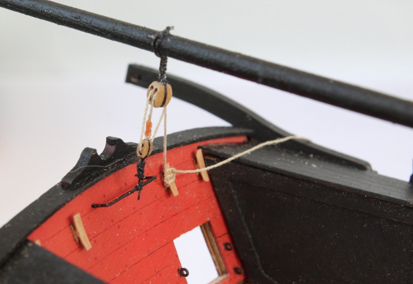
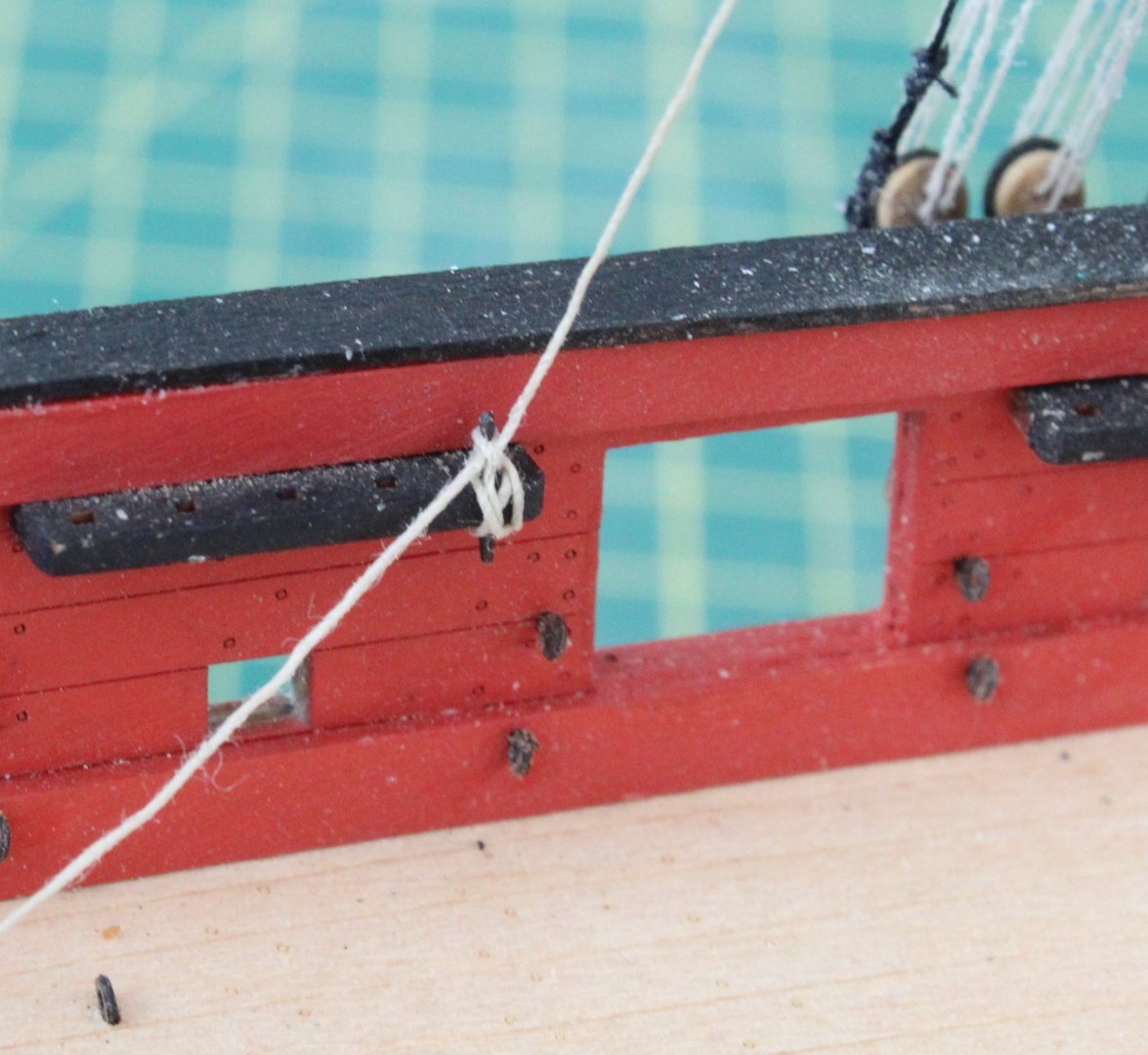
Working on fitting the anchors today. I am using the following picture as the basis for this task. The first task was to seize the hawse rope to the anchor, as is shown in the next two photos. Next an eyebolt, seized with some 0.25mm natural thread was added to the cathead. The rigging was then reeved through the double block and the cathead, noting I had a senior moment and inexplicably forgot to reeve, as it drops down from the cathead, back through the double block, as can be seen in the next photo. The anchor was then secured to a timberhead. The completed anchor fitting is shown below, noting I have not corrected my error. In the interest of being correct I should correct my mistake but I am not sure if I can be bothered at this stage, noting once built the Harpy will not be on display. My enjoyment is in the building of the models and once completed the tend to languish on the sidelines. I do have two small Vanguard model fishing boats on display in our living room and my completed Sphinx model is currently on display in our dining room. I did sell my completed Indefatigable model to a Captain Horatio Hornblower fan where it is on display and can be appreciated. I will repat the above for the port side anchor and this time I will try to reeve the thread correctly.


- 241 replies
-
- 6
-
-
- Vanguarrd Models
- Harpy
- (and 1 more)
-
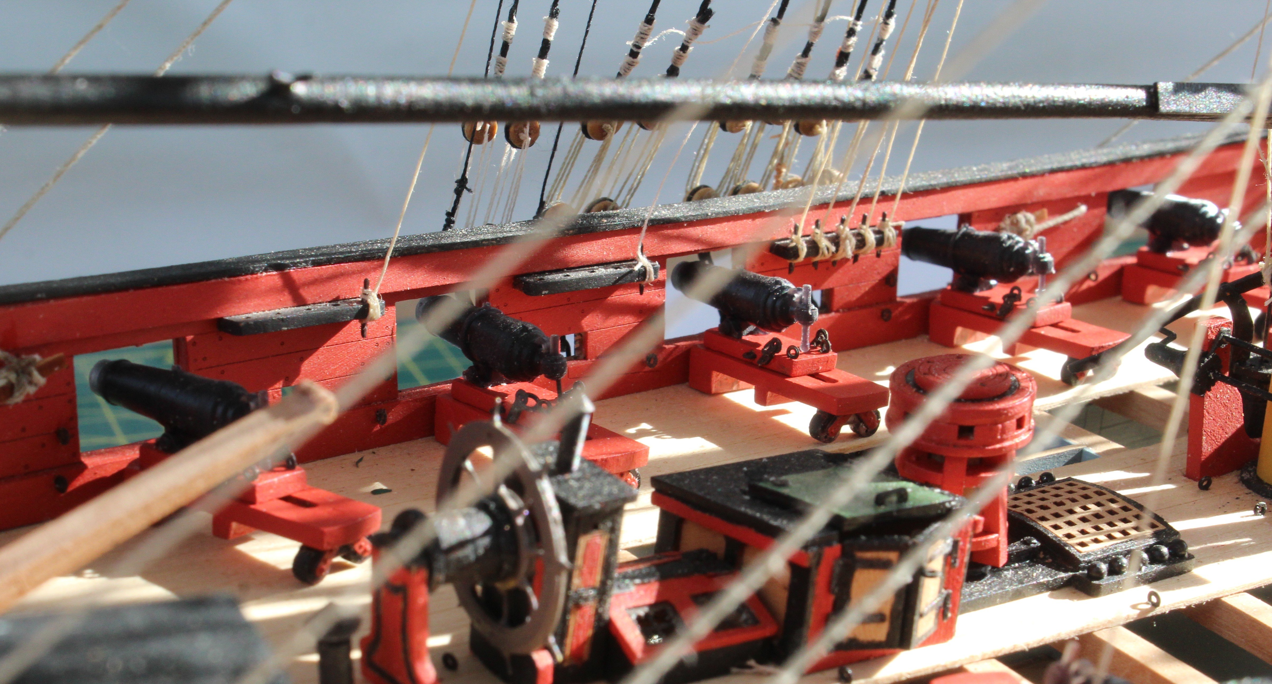
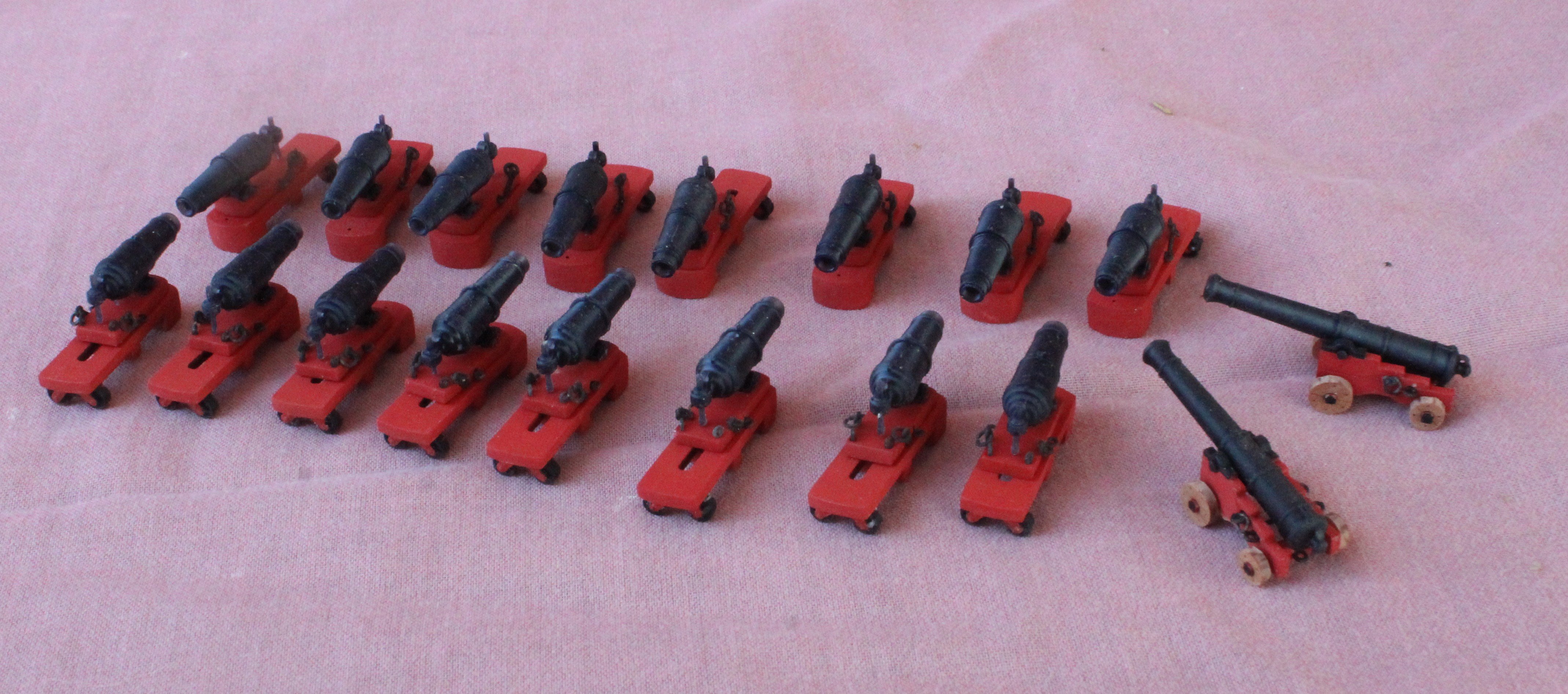
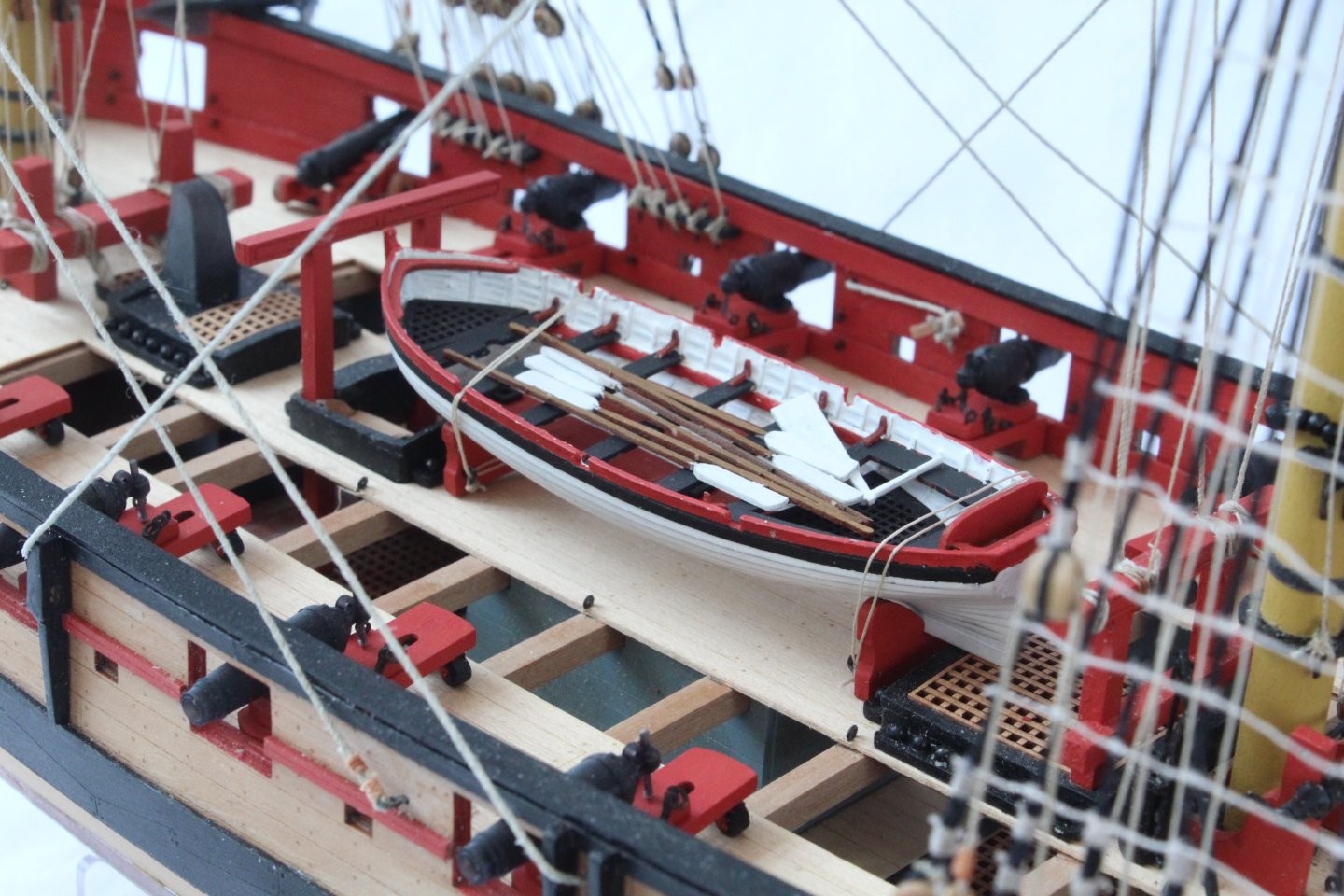
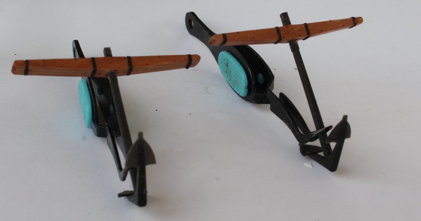
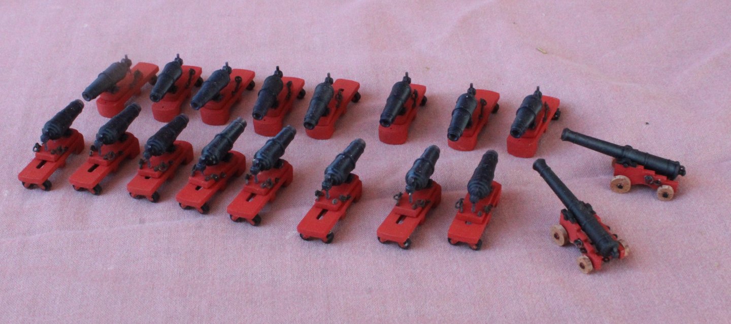
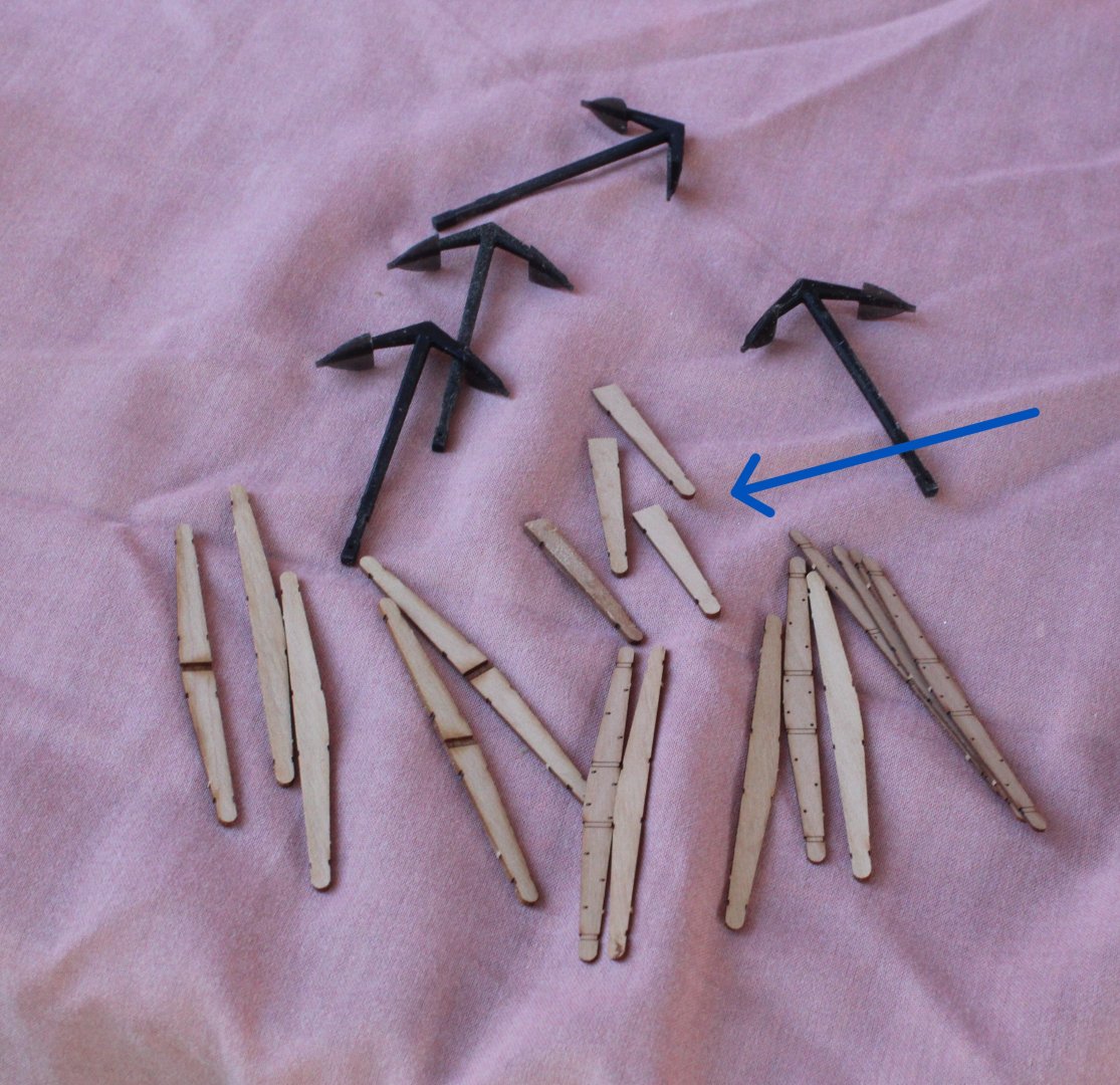
Just a quick update. I have now made two anchors and, as indicated in my last post, I am not going to fit the other two anchors. The completed anchors have had a coat of varnish. The weaponry has been placed on the deck.


- 241 replies
-
- 11
-
-
- Vanguarrd Models
- Harpy
- (and 1 more)
-
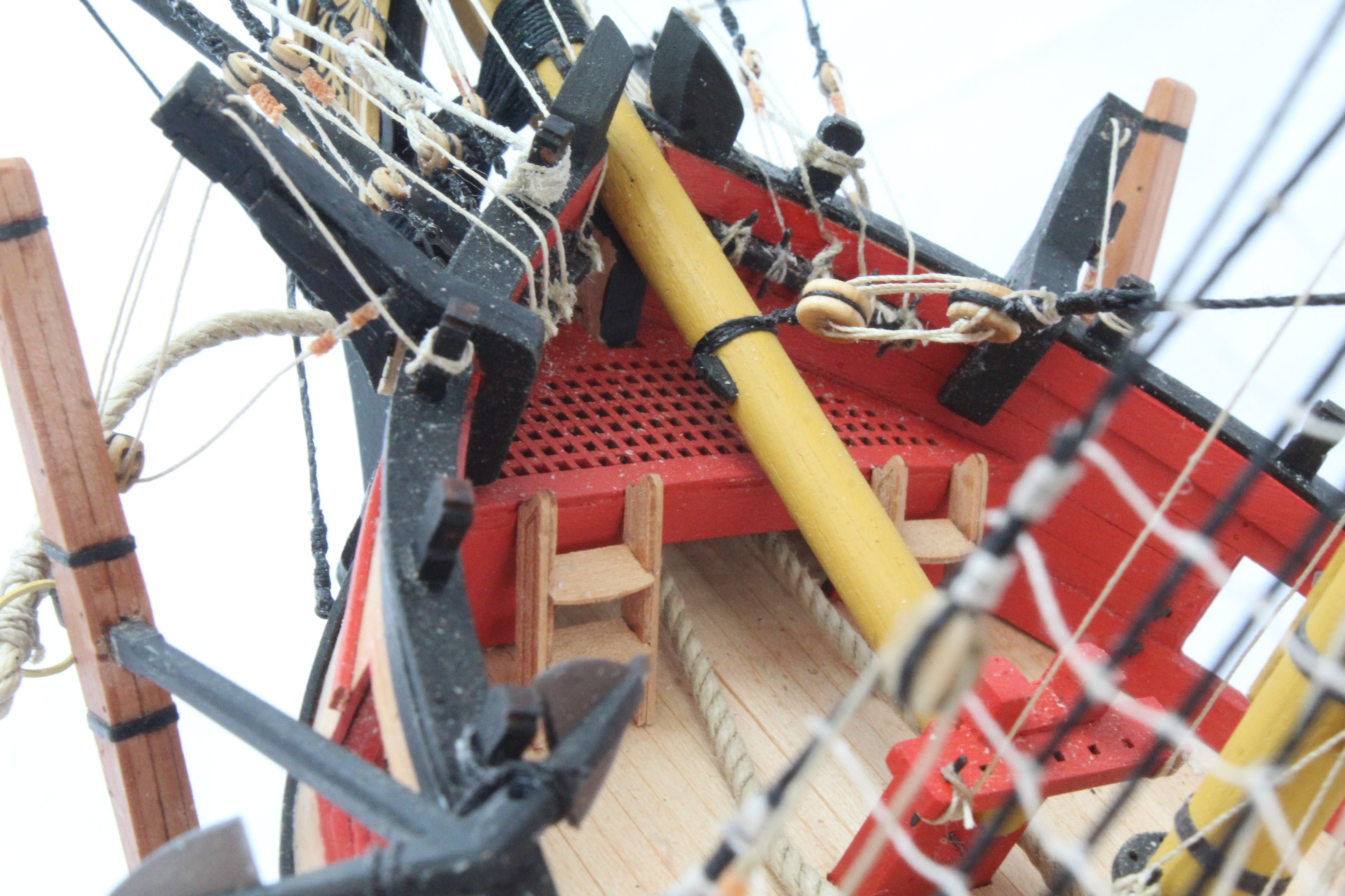
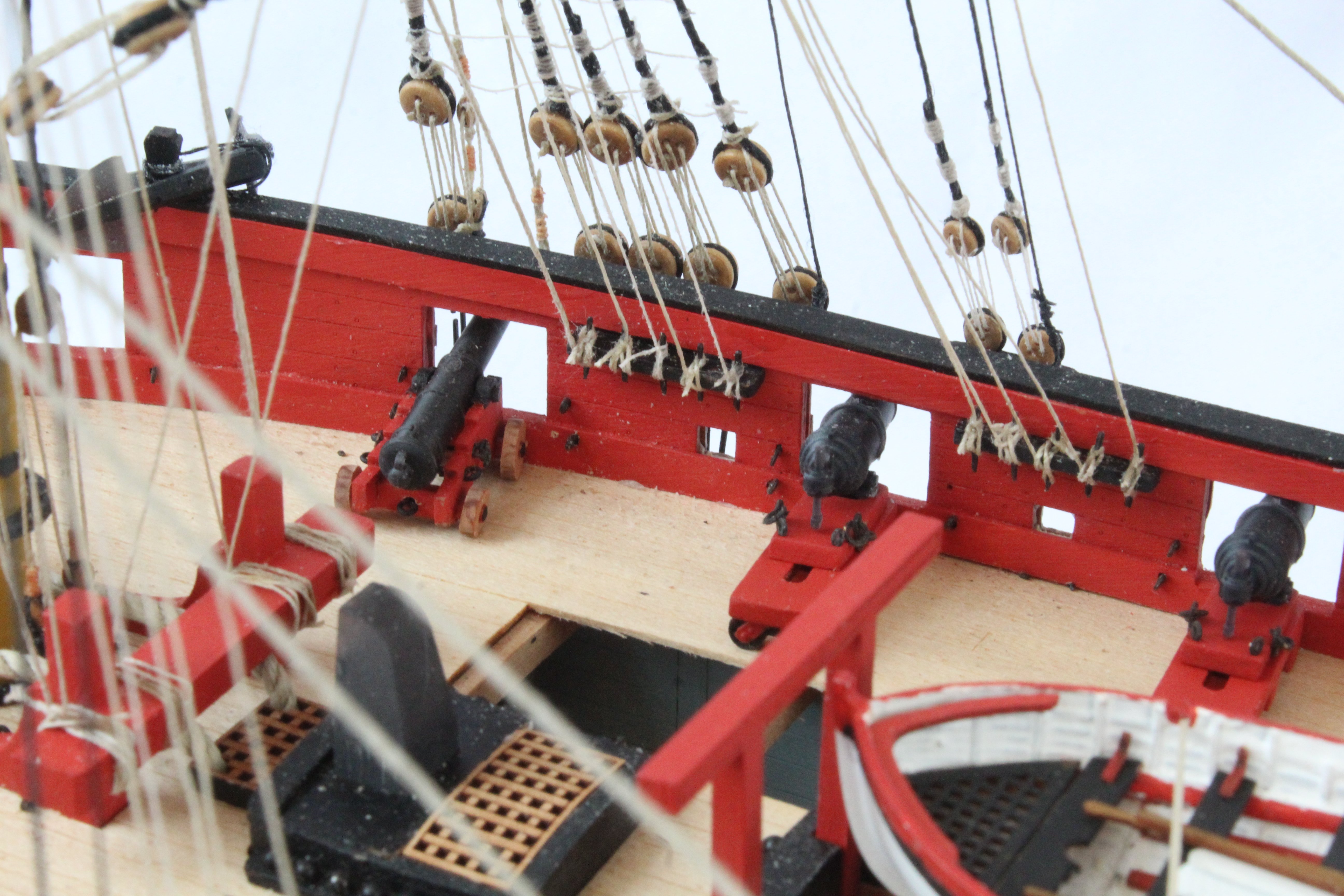
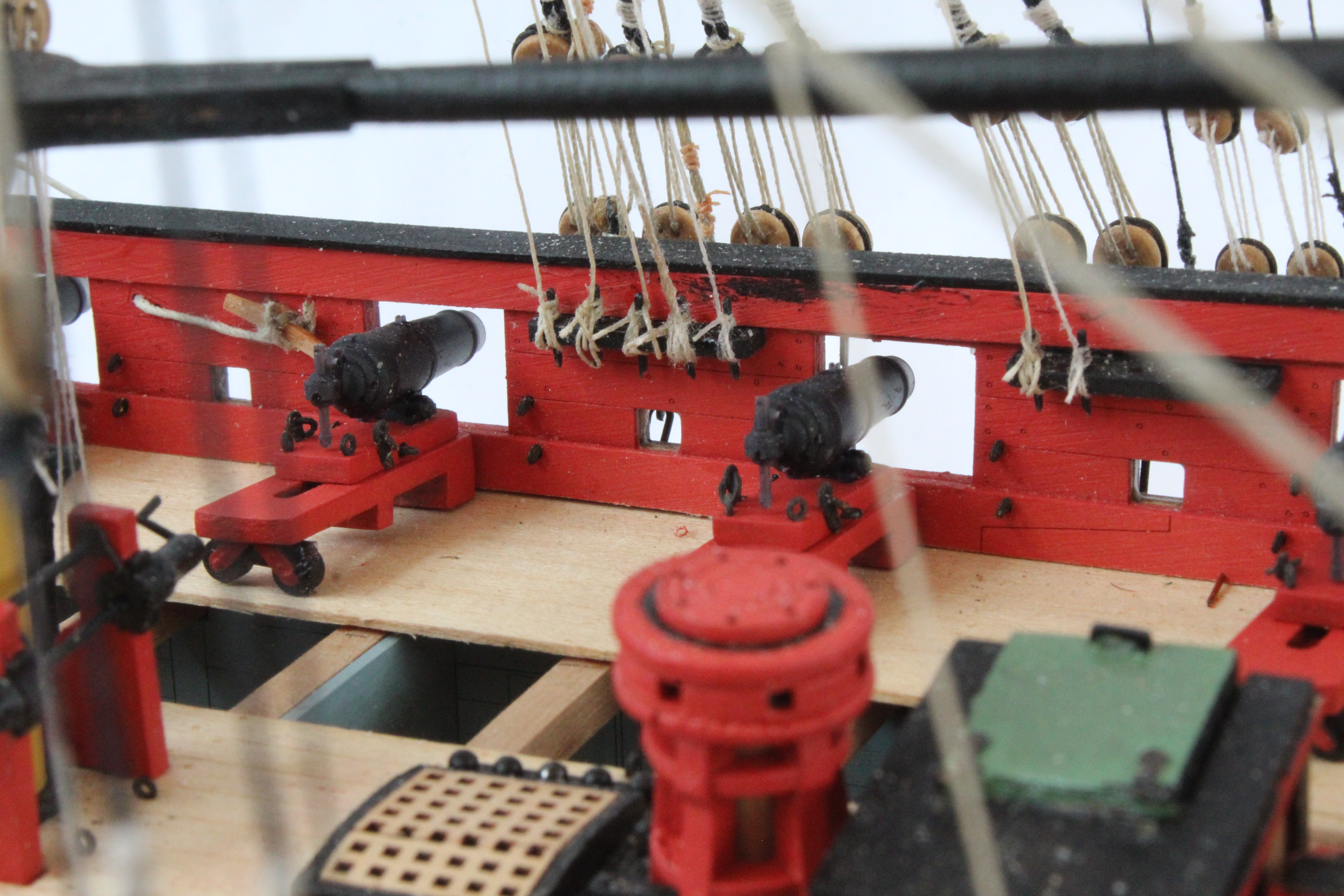
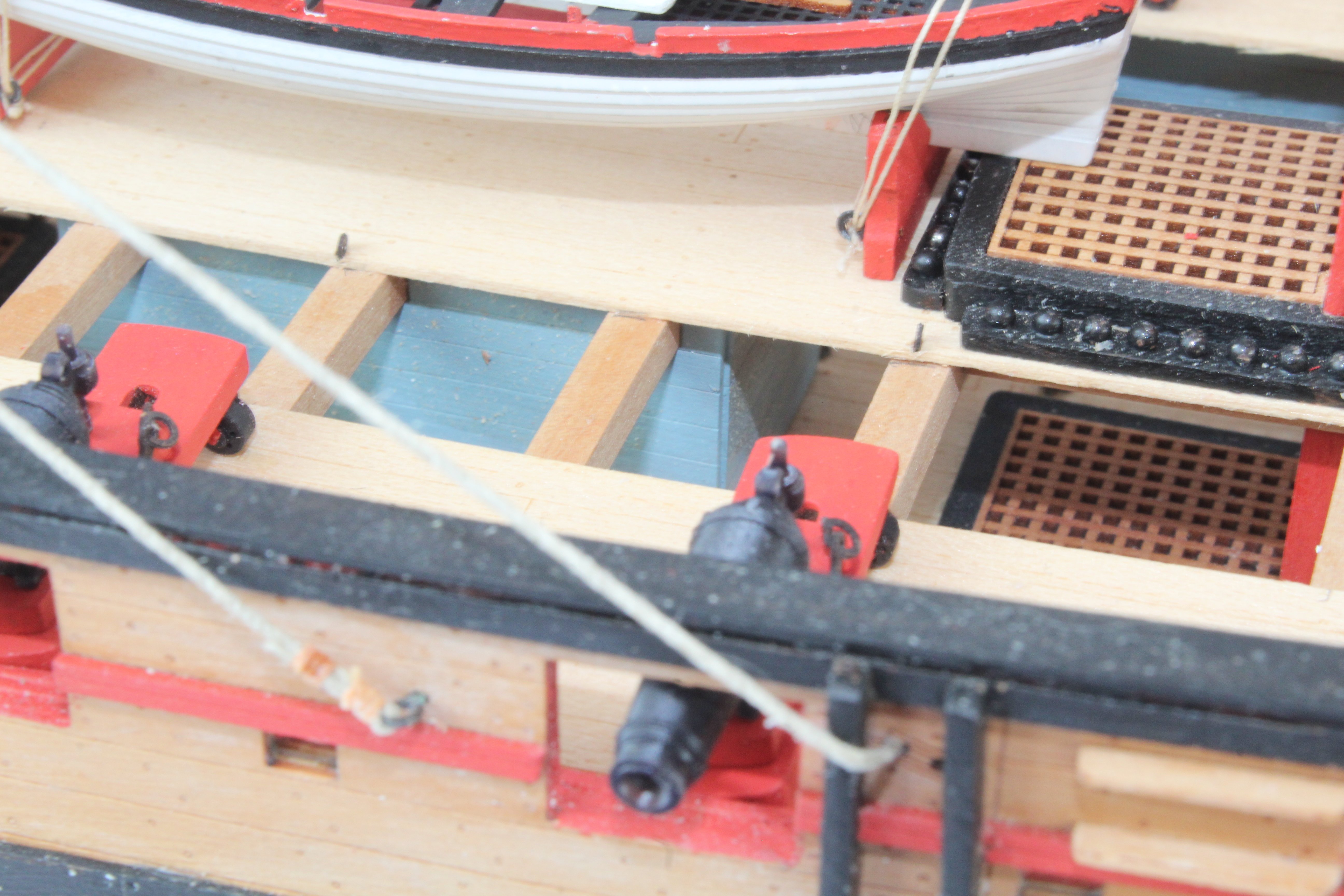
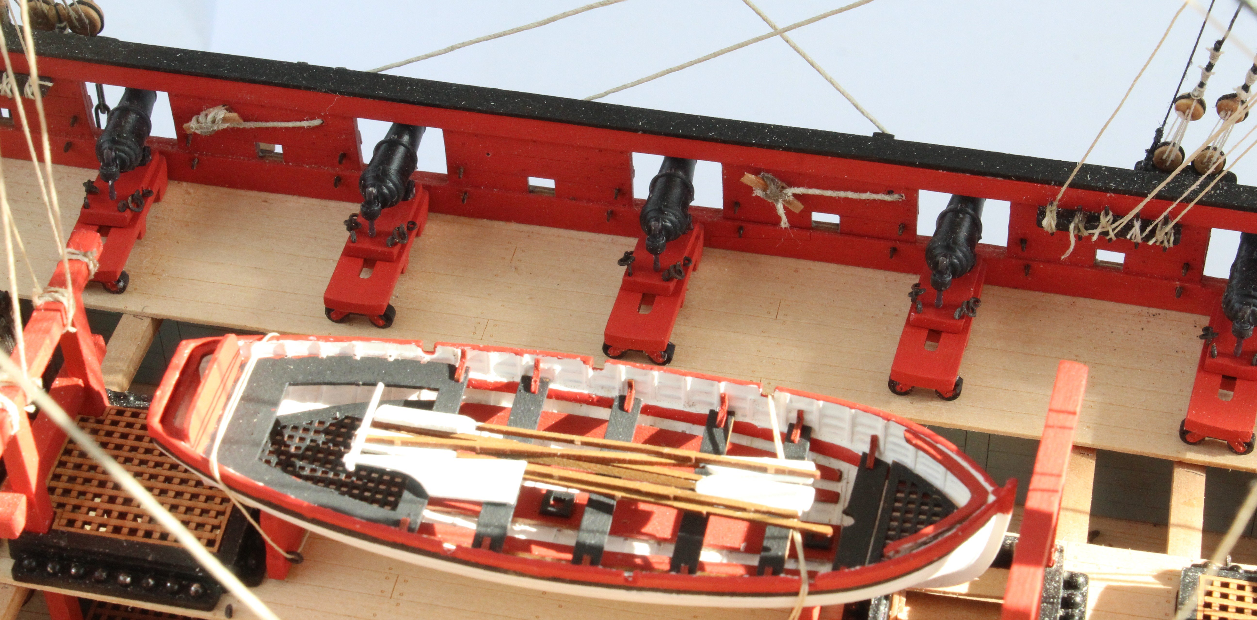
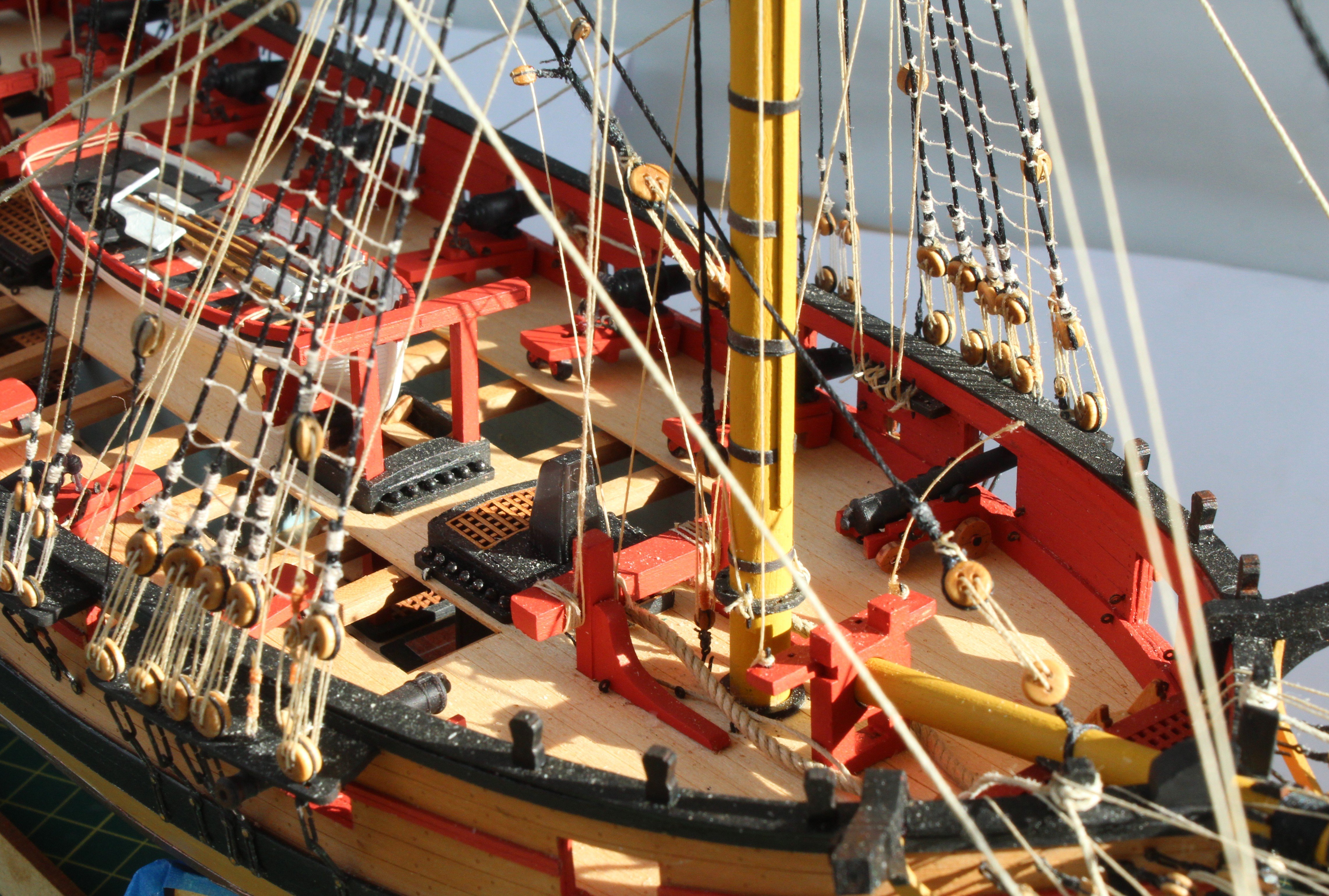
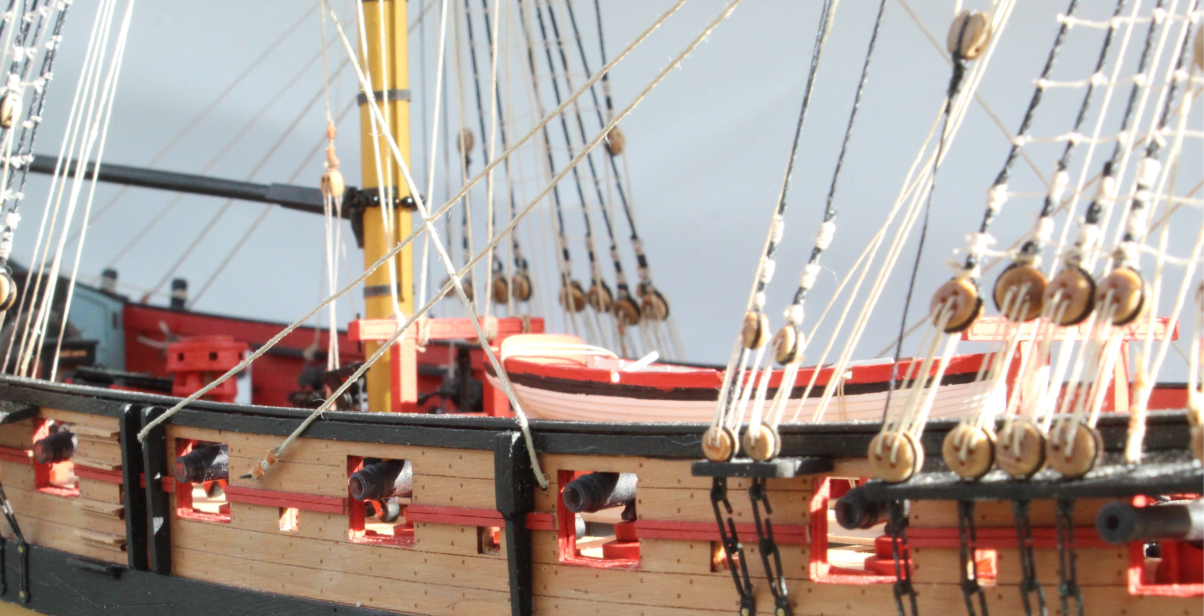
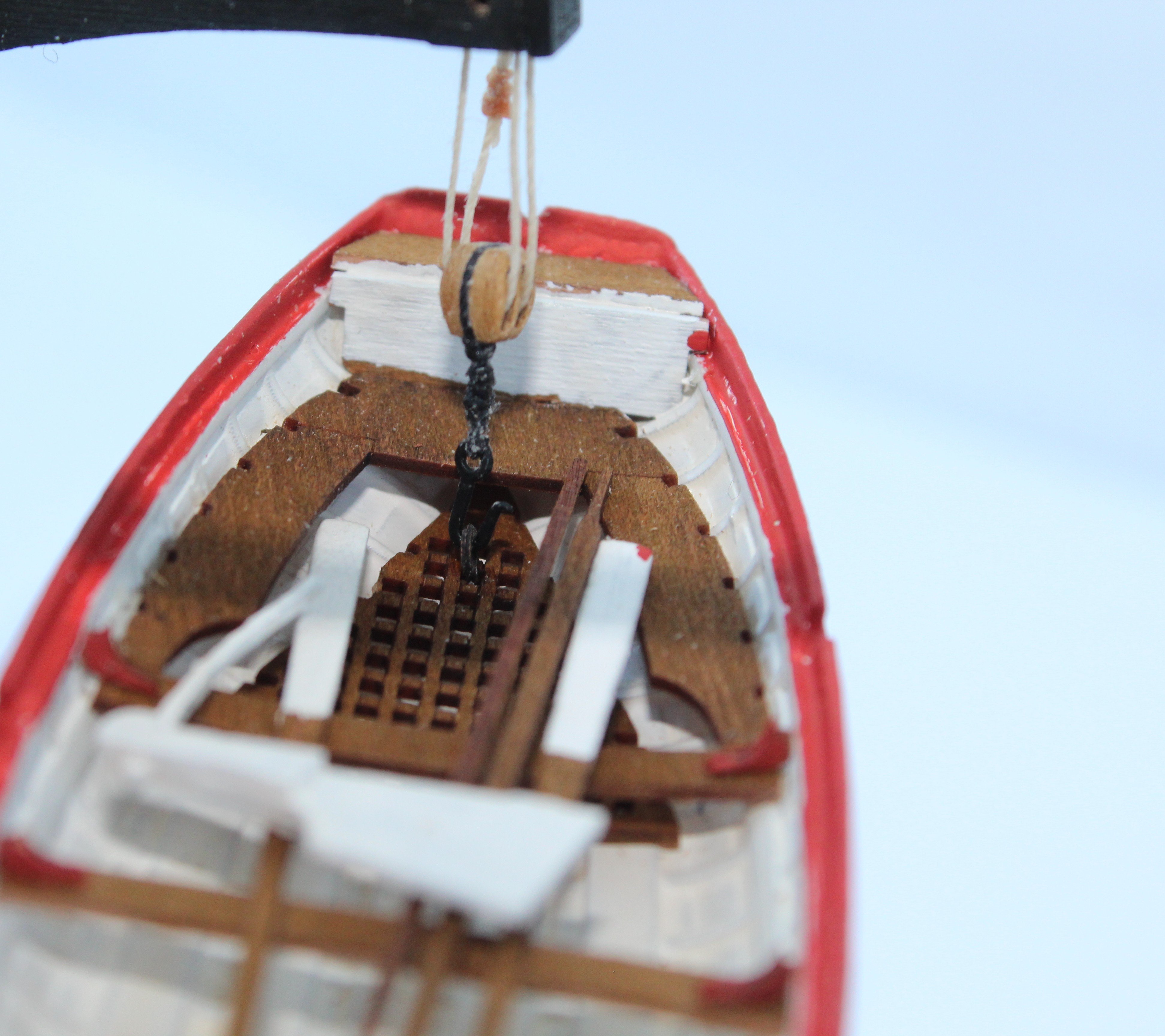
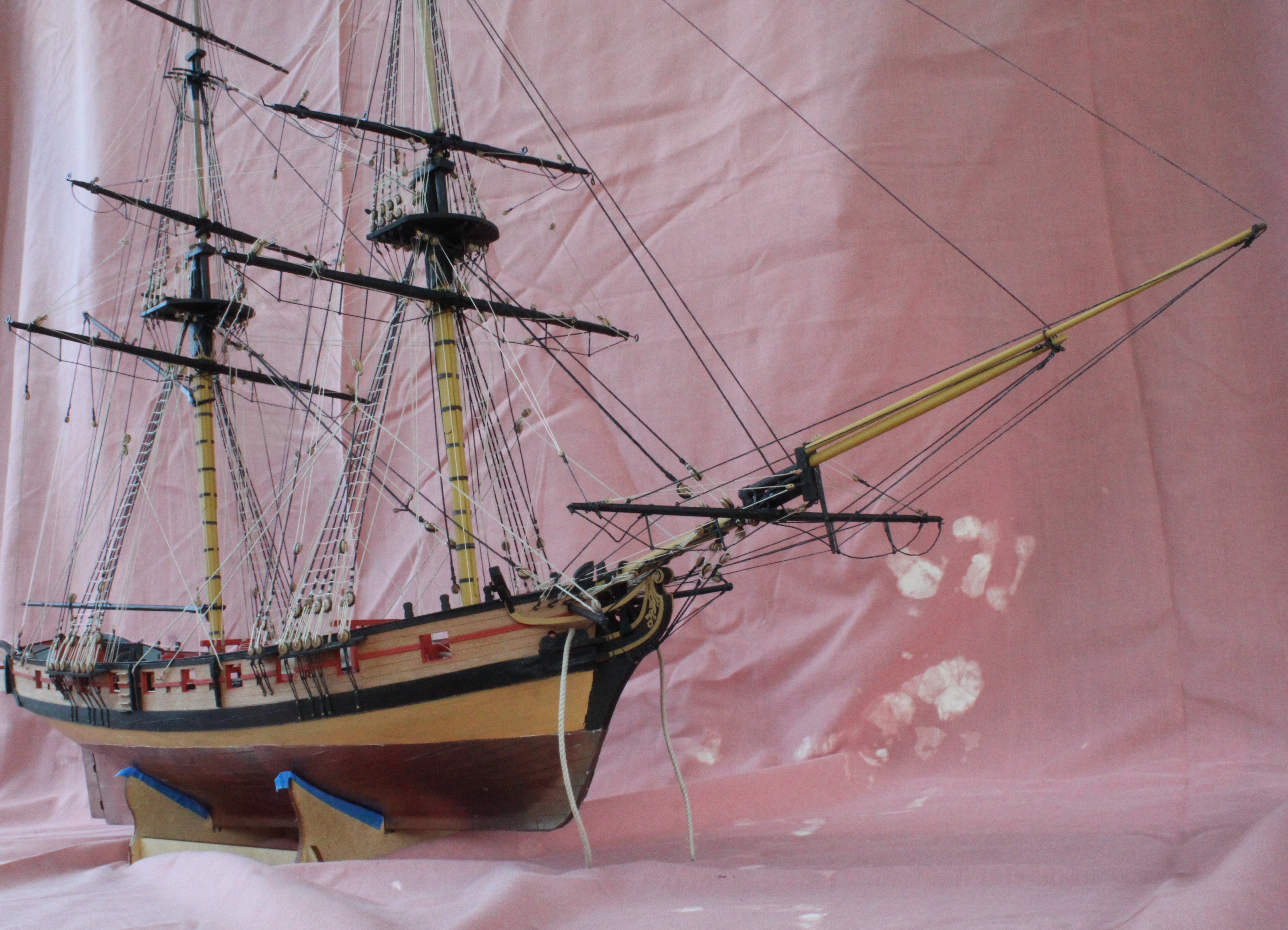
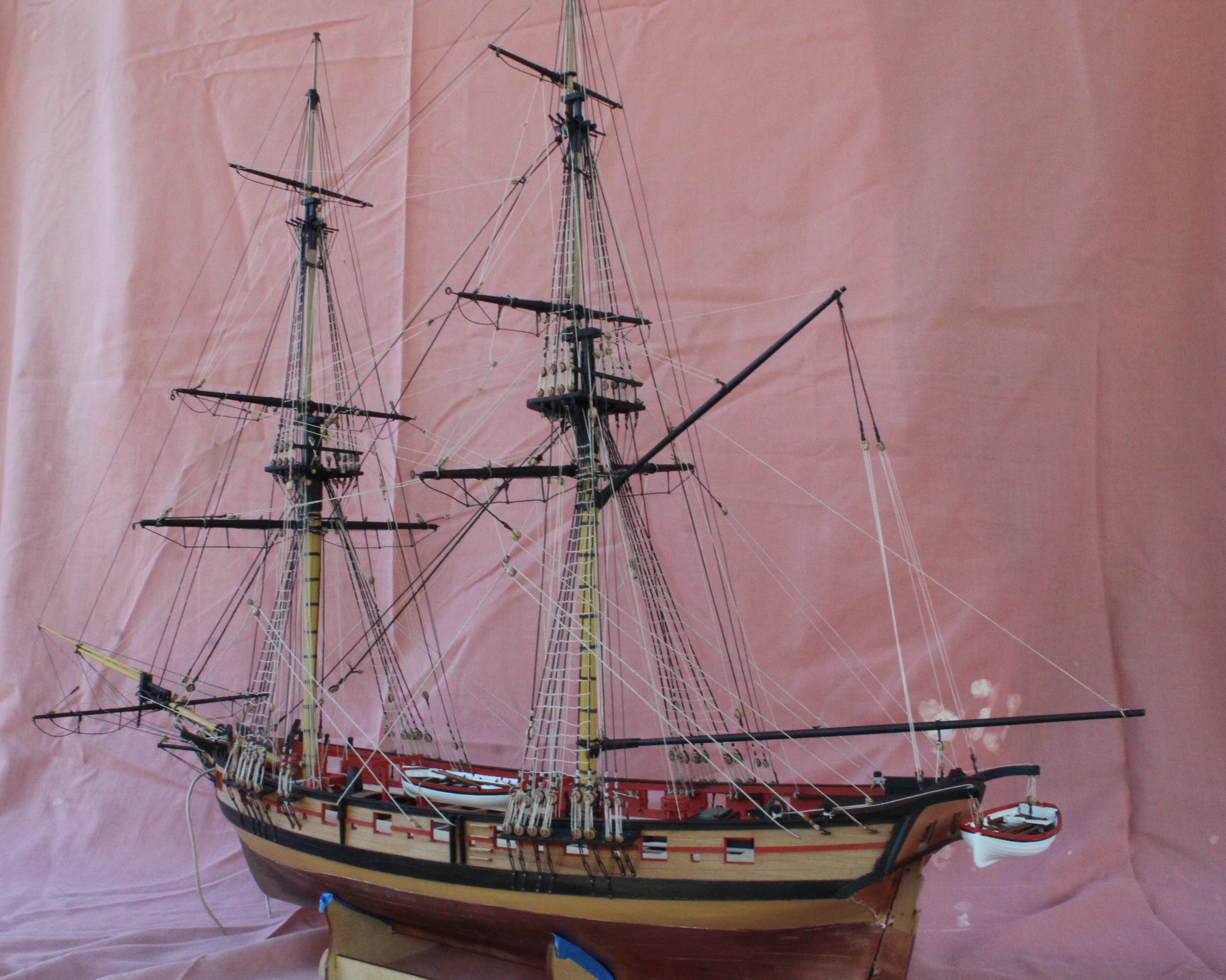
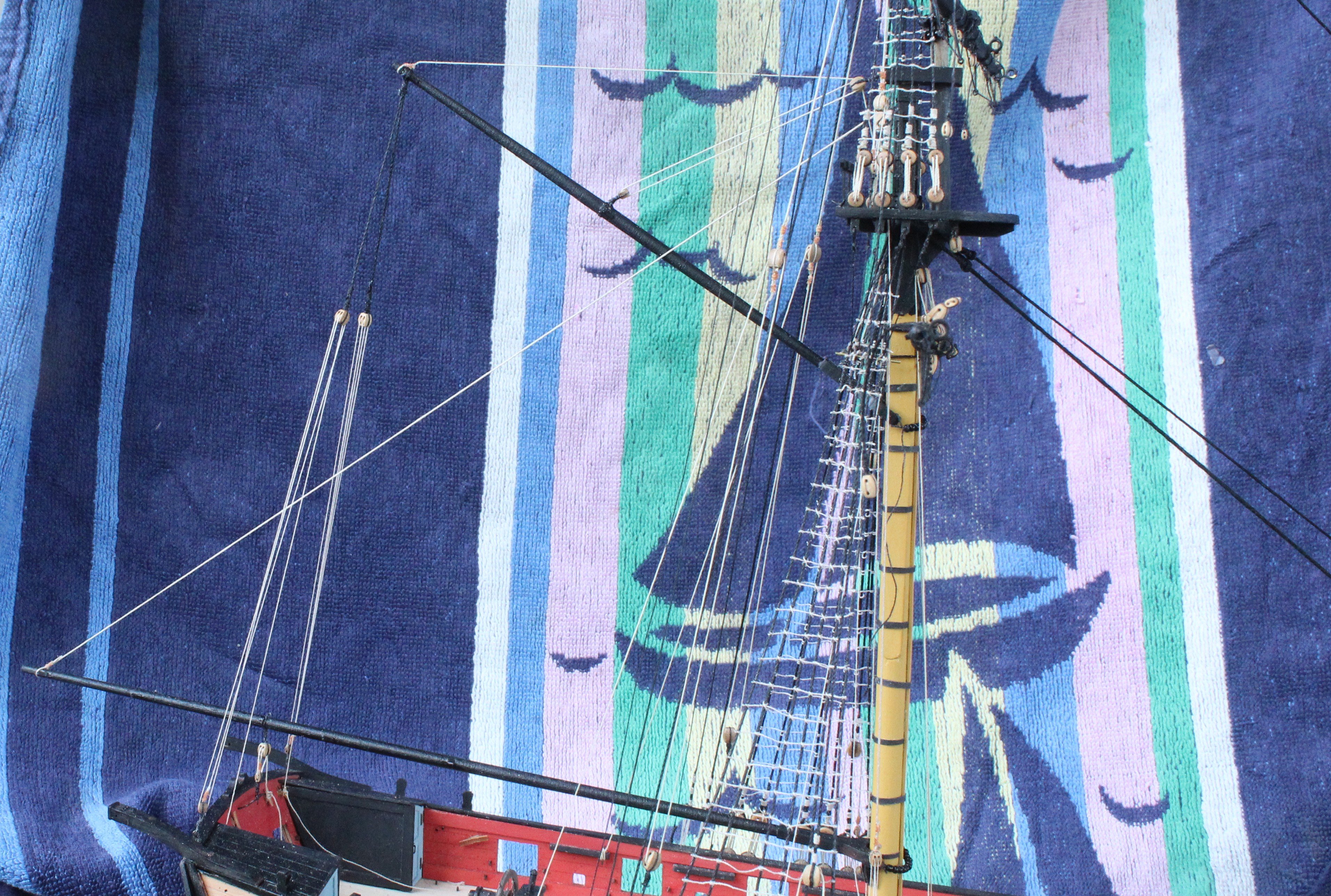
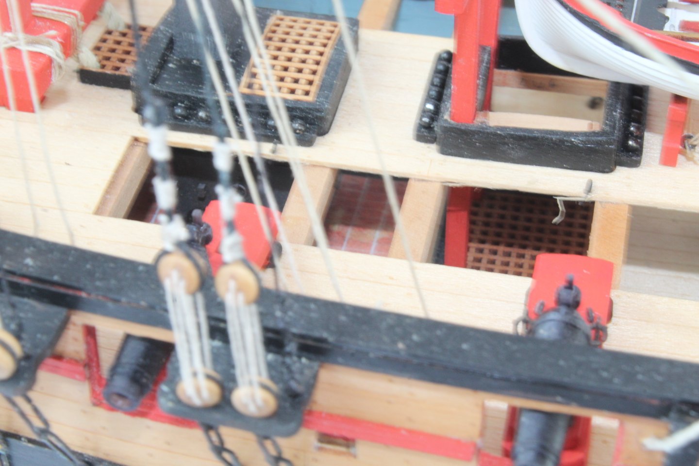
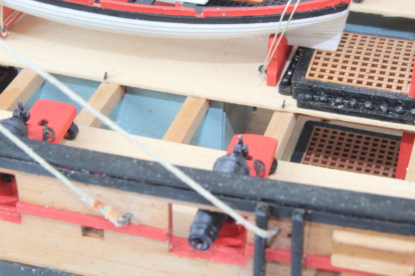
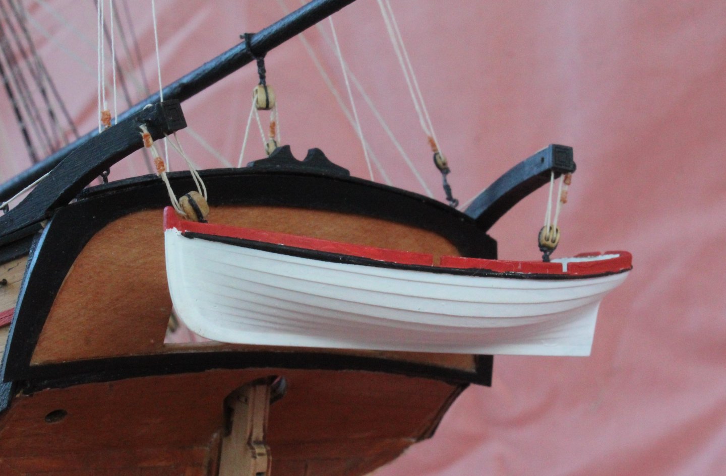
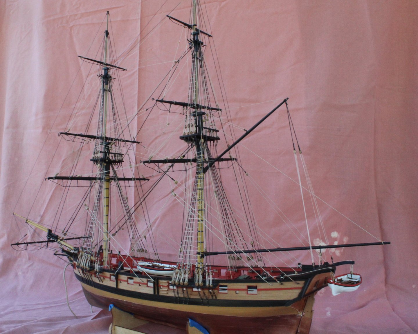
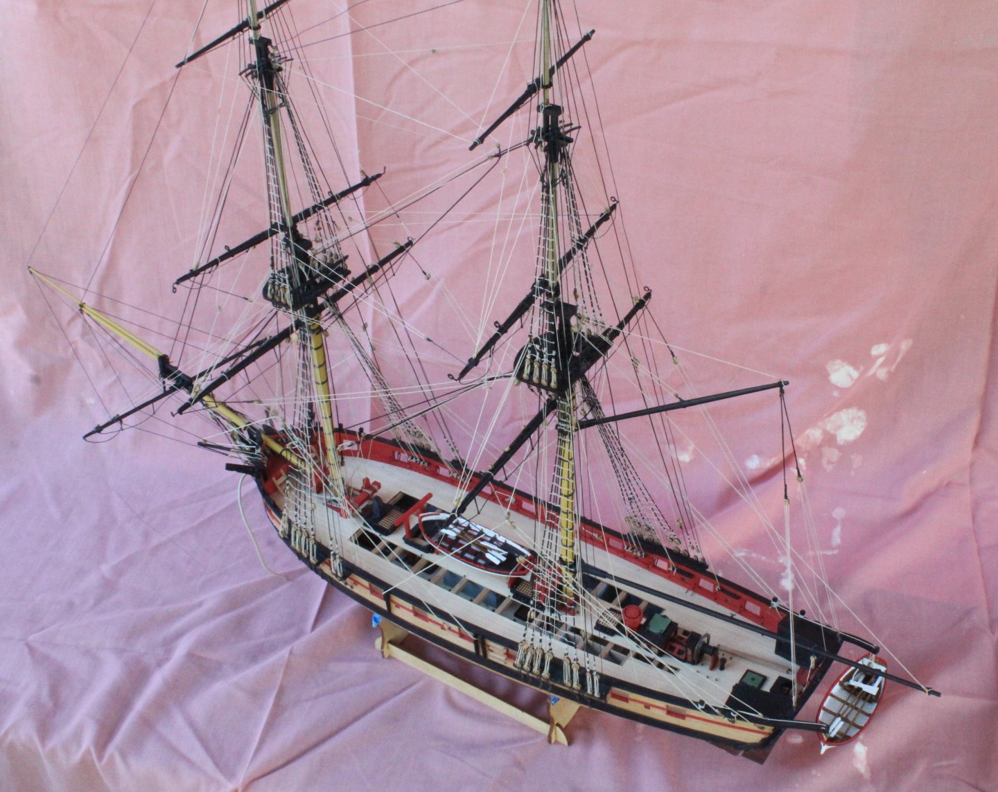
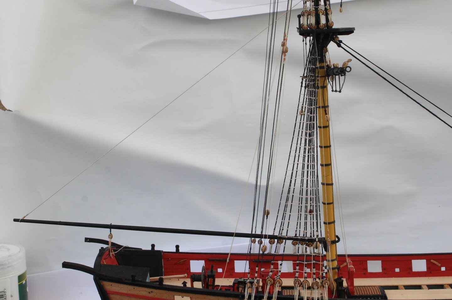
The end is in sight as I only have to install the weaponry, anchors and make the perplex stand. I have not added the bowline rigging. I am still in two minds weather to add these or not. I might redo the spritsail yard braces as it is currently (unintentionally) set at a jaunty angle to bowsprit. The first task today was to hang one of the 18ft cutter from the rear of the ship. I opted to use a hook and eyelet to hold the cutter. Next the 22ft cutter was added to the deck. The cannons have been brought out of storage and are ready to be added. I am only planning to fit a set of anchors on this model. As can be seen in the photo below I have had a few issues with breakages. After much deliberation I placed an order for the The Baltimore Privateer Schooner Grecian as I think this fits in better with the timeframe to complete and to then be ready for the release of the Surprise. The Grecian is not a boat that really appeals to me but I think it will be an interesting project to complete nonetheless I have taken a few photos of the current Harpy build status, as shown below. The white blotches on the background are paint stains as the backing used is an old decorating dust cover.


- 241 replies
-
- 8
-
-
- Vanguarrd Models
- Harpy
- (and 1 more)
-
I am also very tempted by the Syren's 3D-printed blocks, especially the deadeyes. I might order as set of deadeyes for my next build.
- 241 replies
-
- 1
-
-
- Vanguarrd Models
- Harpy
- (and 1 more)
-
Machined ones, much better than the standard kit ones.
- 241 replies
-
- 1
-
-
- Vanguarrd Models
- Harpy
- (and 1 more)
-
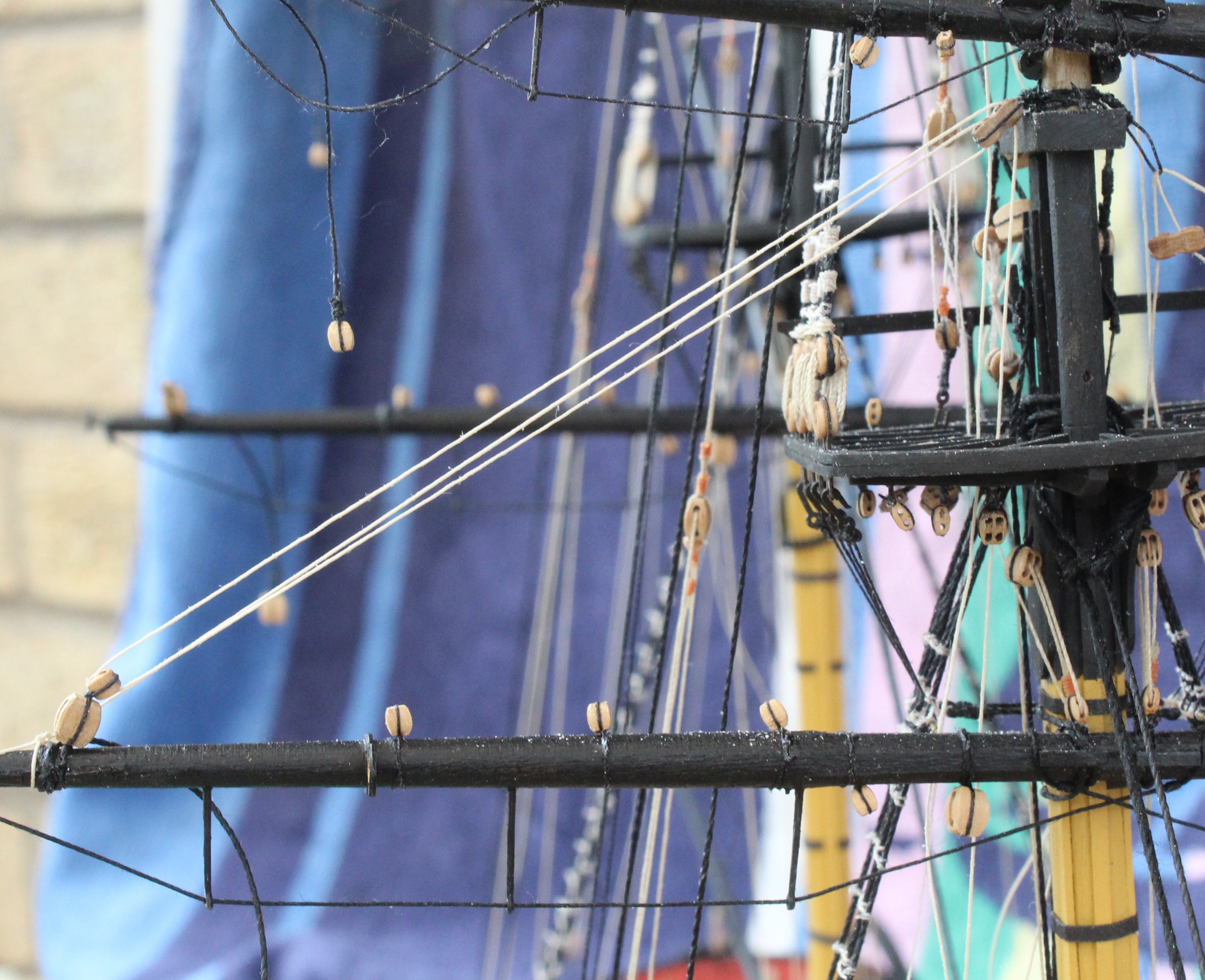
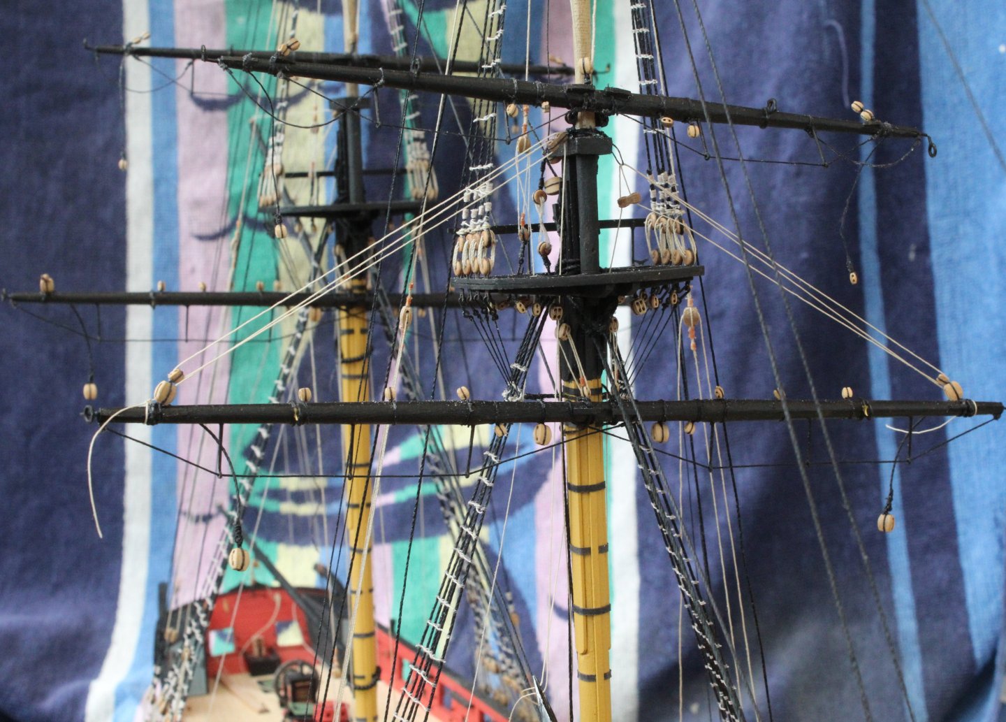
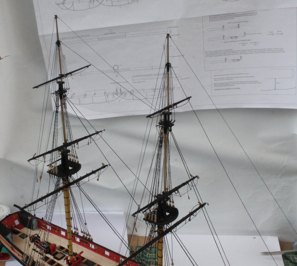
Work is progressing nicely on adding the braces for all the various yards. I have run in the brace rigging for all yards on the left hand side. Once I have run in the right hand right hand side rigging the braces can be tensioned and belayed. In the following set of photos I have shown where all the rigging has been run. There is some fuzz on rigging lines which is not visible to the naked eye. As the end of this project nears I am thinking about which model to build next (as I wait in the wings for Jim to complete the prototype build for the Surprise). I am currently considering either the The Baltimore Privateer Schooner Grecian or HMS Speedy. I have previously partly built HMS Speedy but had to ditch the project partway through the build. I would like to build the HM Brig Sloop Flirt - Master Shipwright Edition but as this kit is currently out of stock so that is not currently an option. Main Yard Braces Main topsail yard braces Main topgallant yard braces Fore Lower yard braces Fore Topsail braces Fore topgallant braces Spritsail yard braces


- 241 replies
-
- 5
-
-
- Vanguarrd Models
- Harpy
- (and 1 more)
-
I have now completed the clews, tacks and sheet rigging. The following set of photos are related to the work related to the lower yards on the main and fore masts. My first attempt at seizing the double blocks failed when tension was applied. thankfully all was good second time around. Belaying the rigging was not to bad to do. I have already started work and rigging the braces, and once that is done the final rigging task will be the bowlines. I would expect to complete the model later his month. The final photo shows the current rigging status.


- 241 replies
-
- 5
-
-
- Vanguarrd Models
- Harpy
- (and 1 more)
-
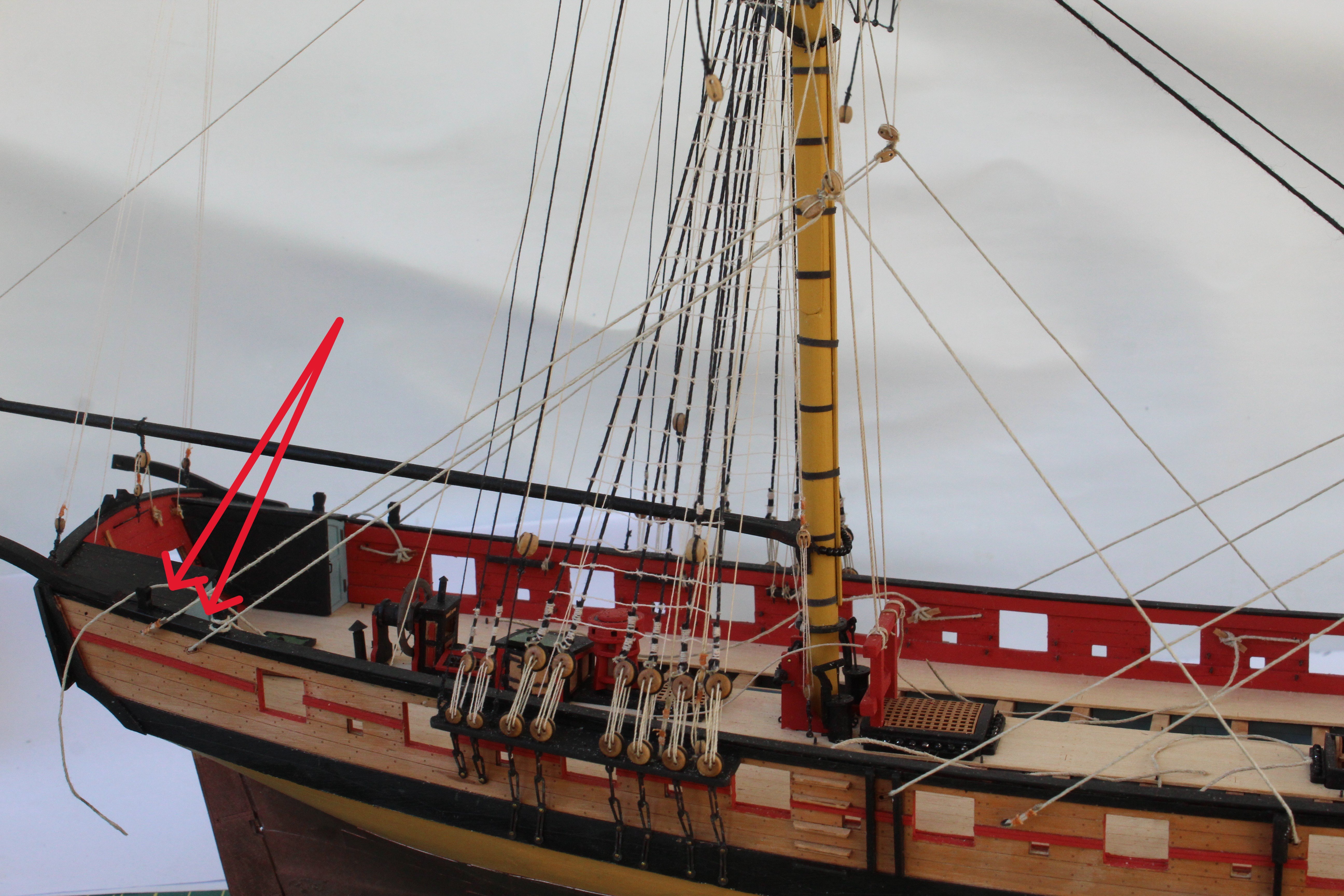
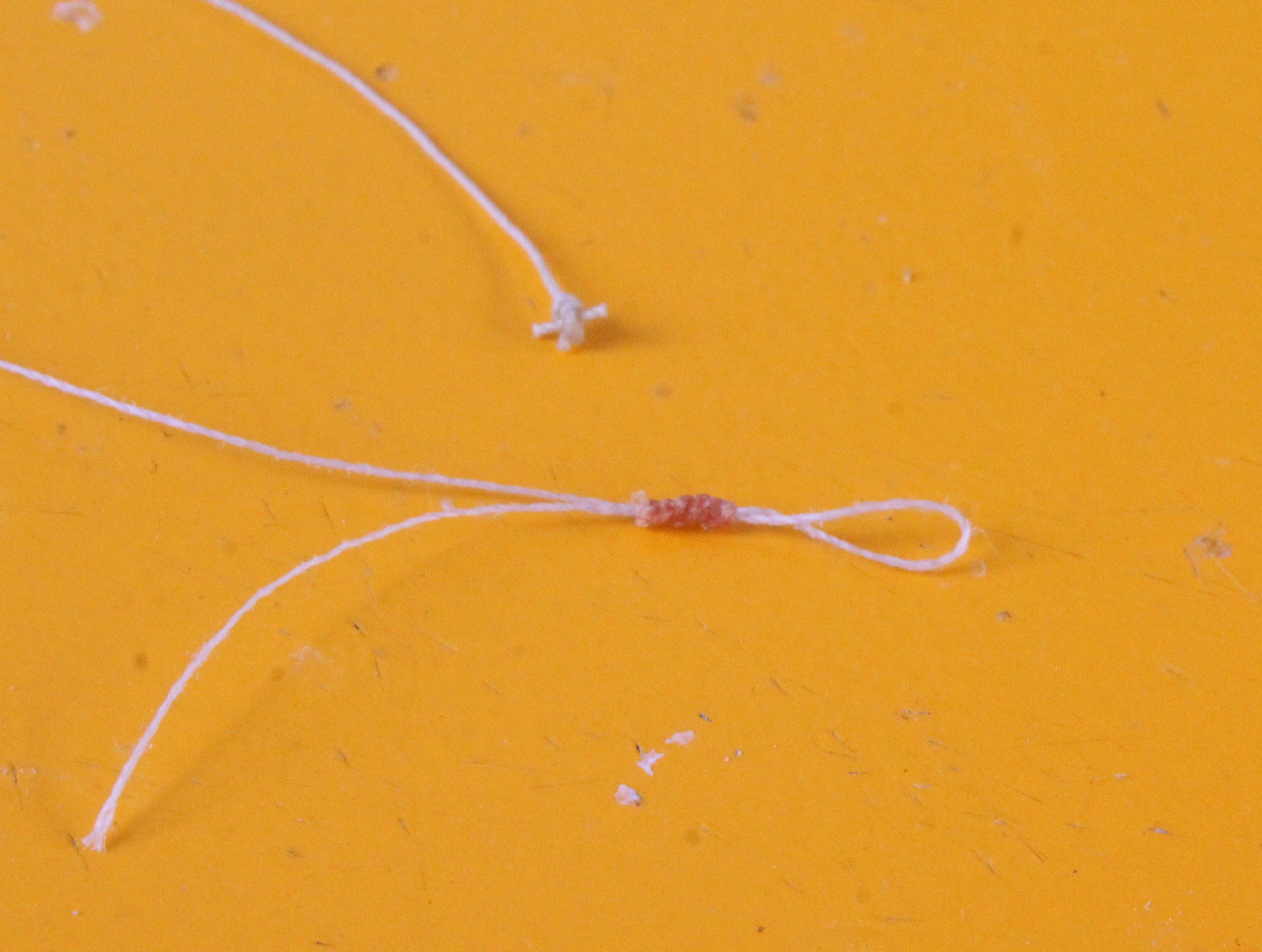
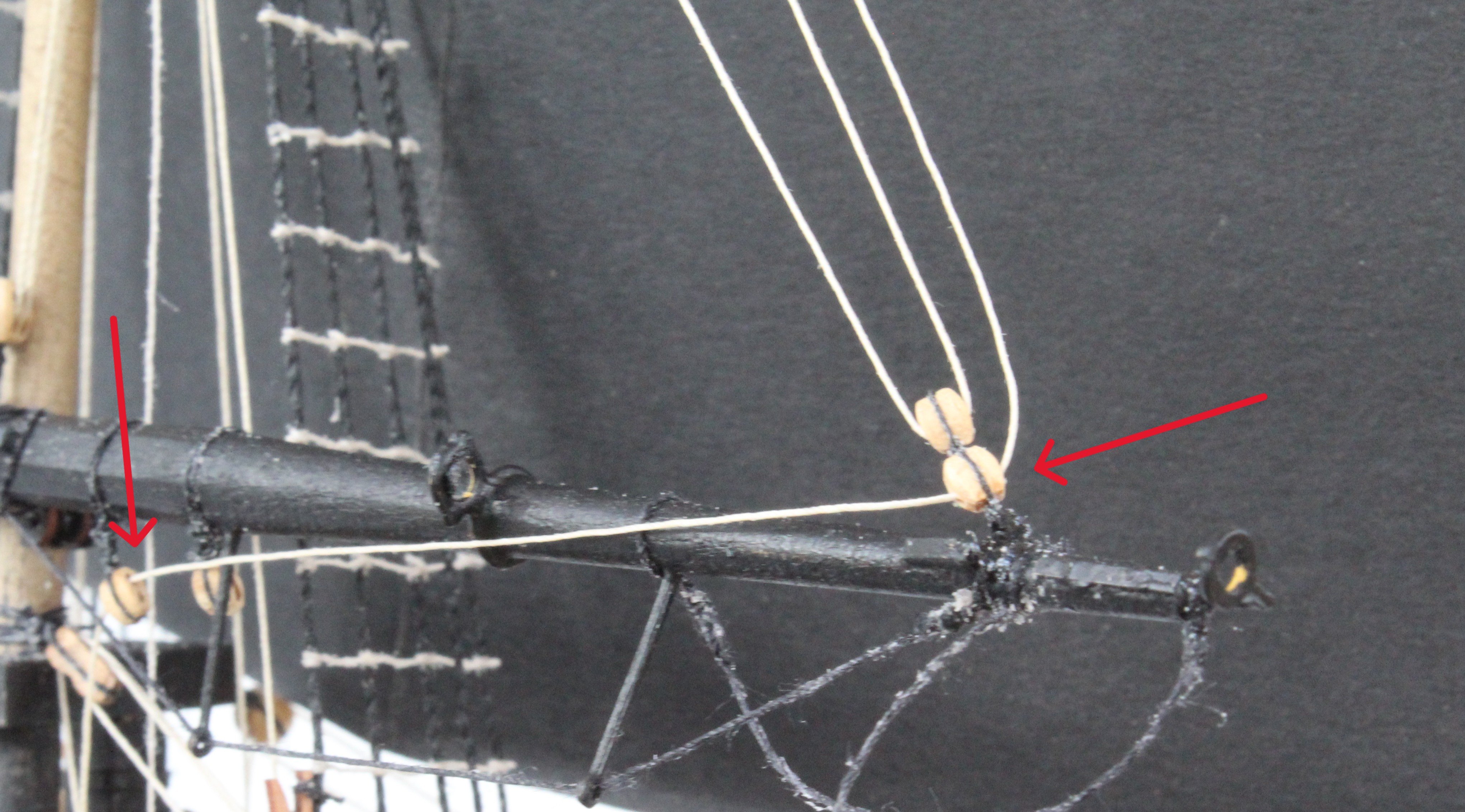
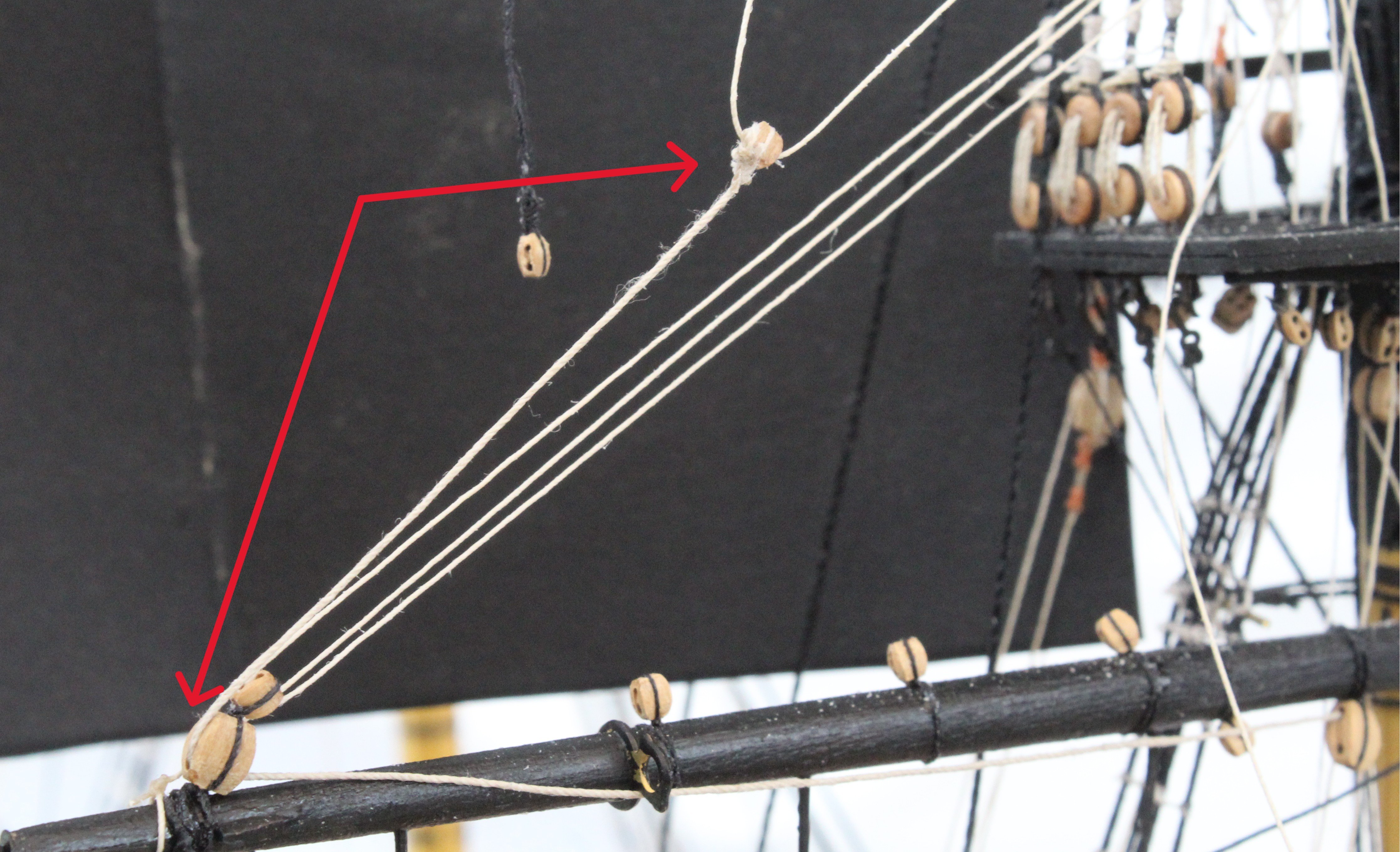
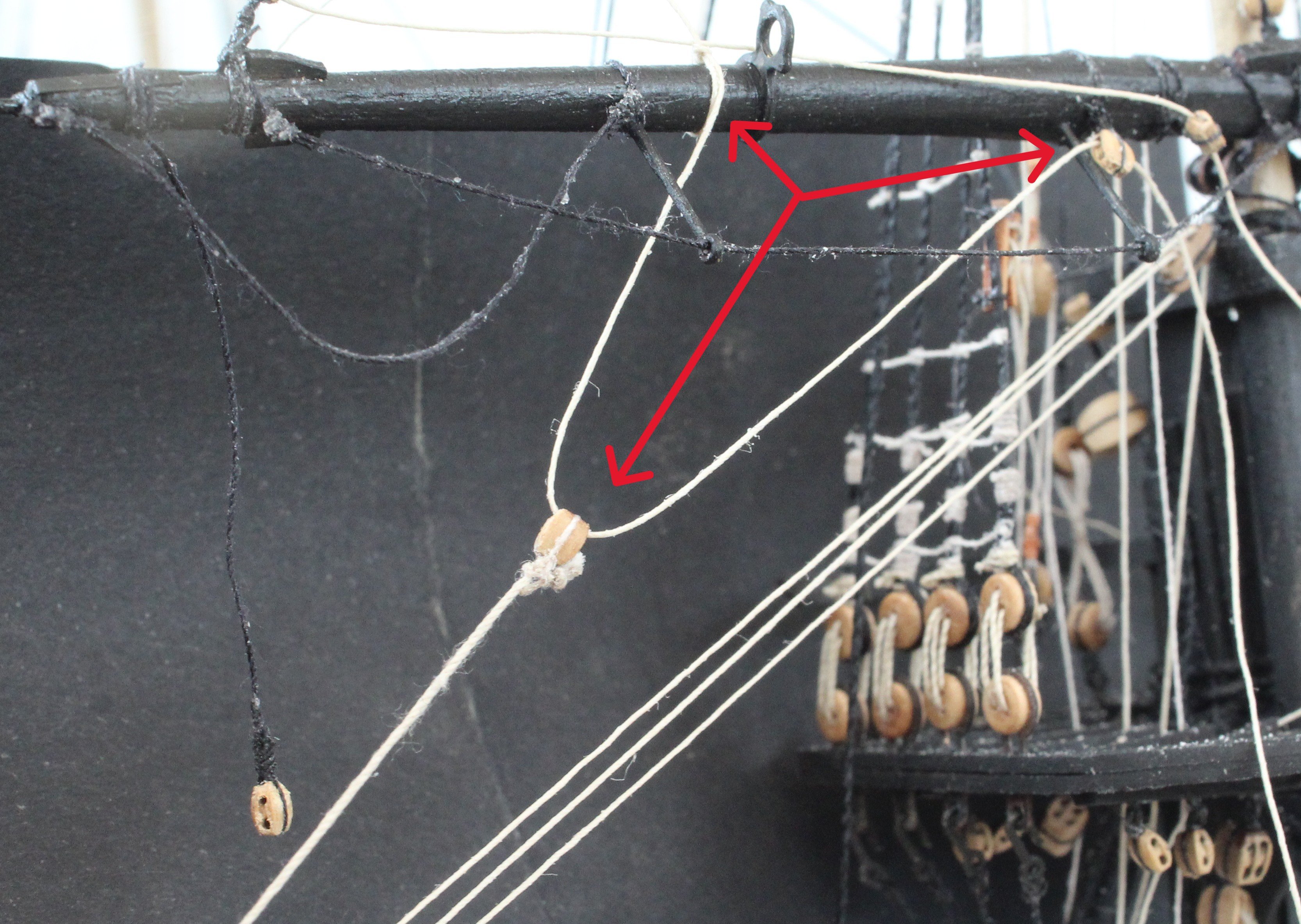
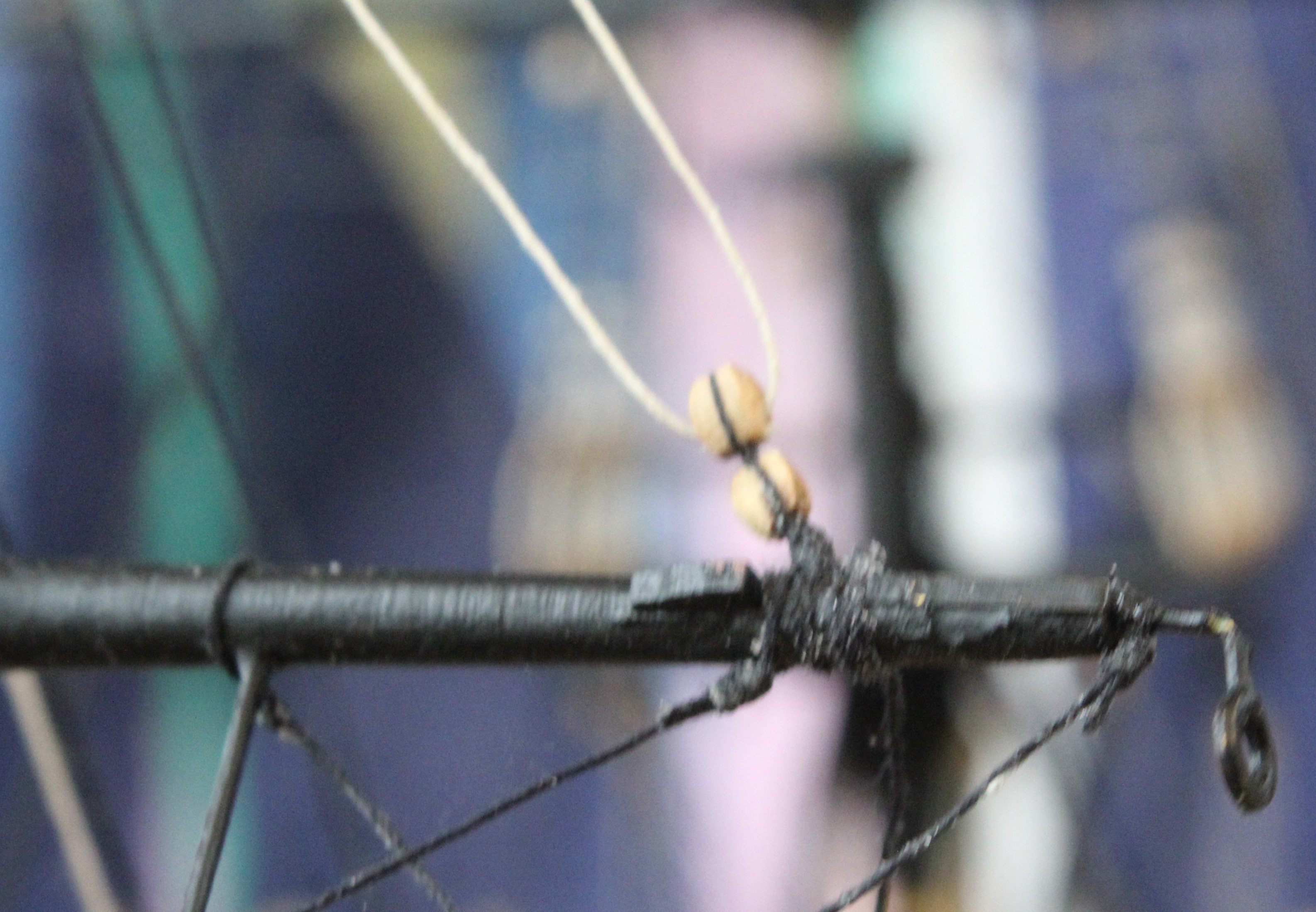
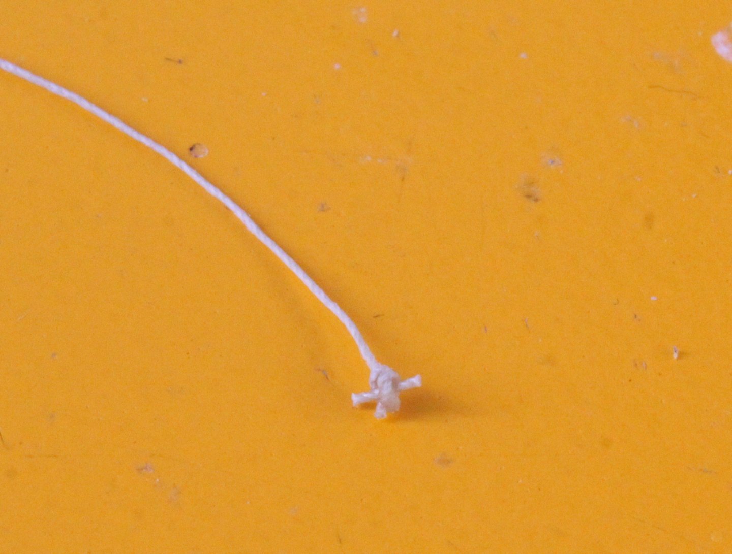
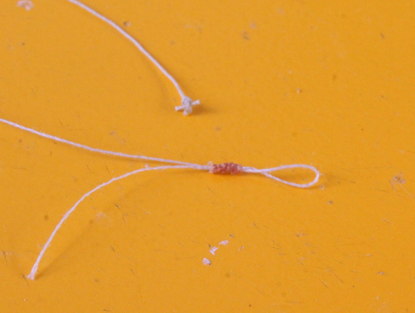
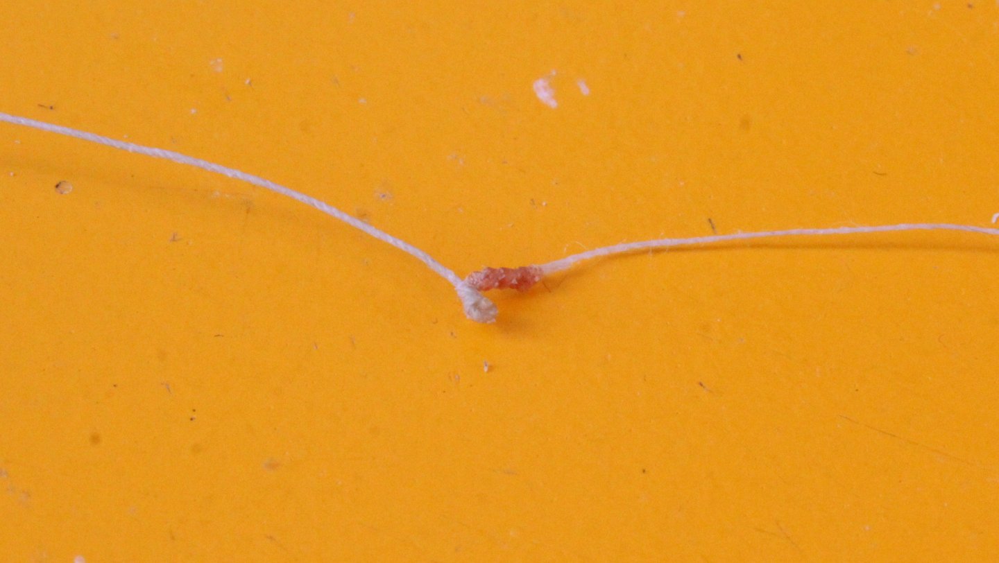
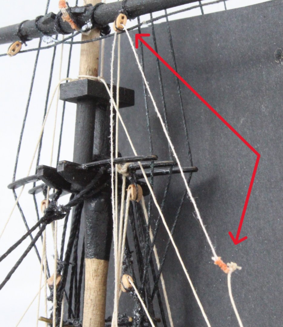
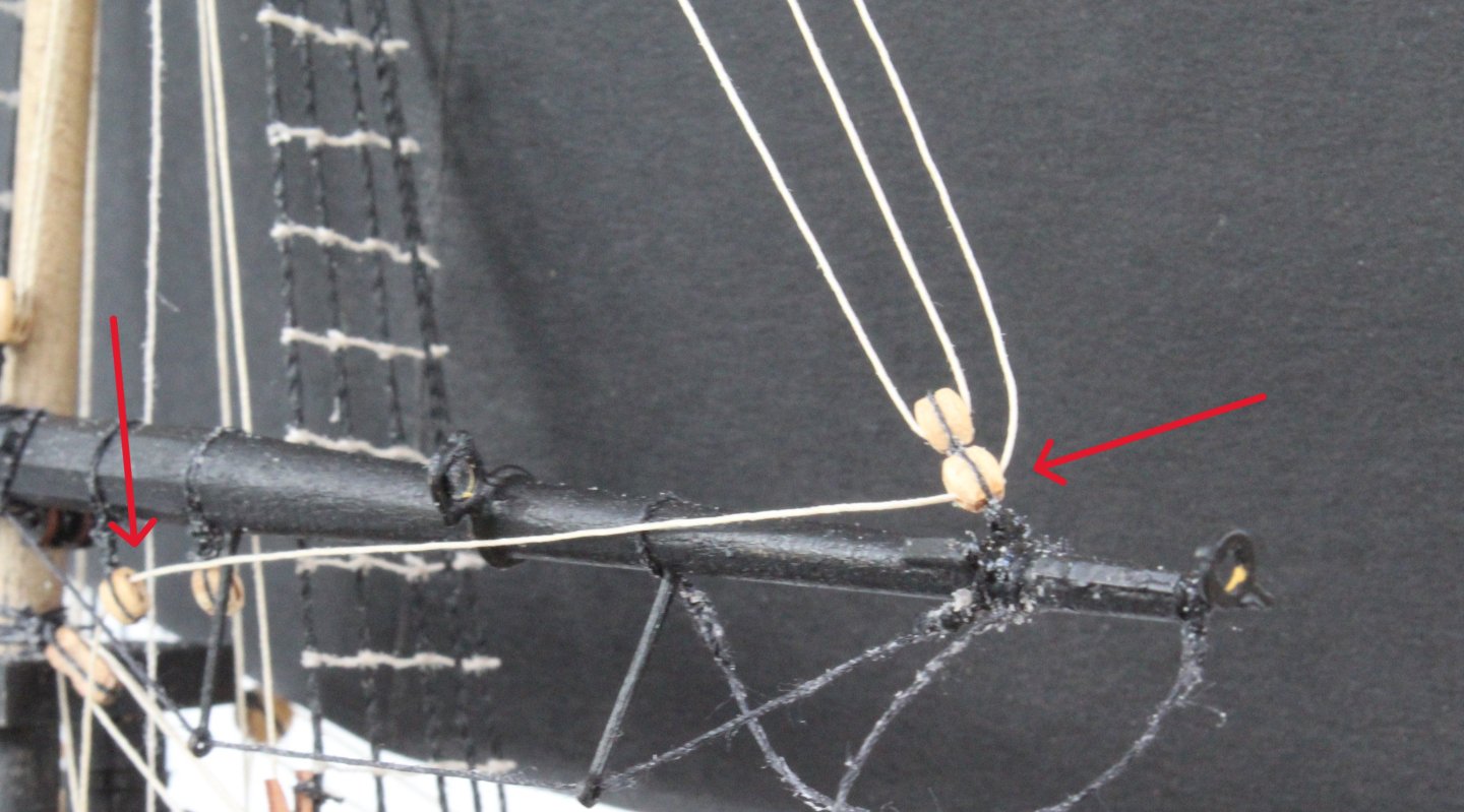
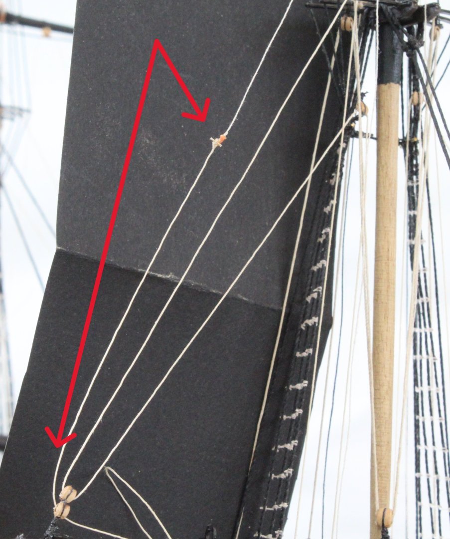
I have made a start on adding the clews, tacks and sheet rigging. The first task was to add pin to the end of a length of thread. The pin is a small length of thread which has been stiffened with ca glue. This is shown in the photo below. The pinned thread is to be passed through a loop. I created the loop in a second length of thread, as shown below. With the pined thread in place the loop is closed up and the excess thread trimmed, as shown in the next photo. In the real world the pin acts a quick release mechanism. The next set of photos shows the rigging in place, noting it has not be tensioned or belayed. The red arrows indicate the rigging, The pin release rigging between the topsail and main yard is attached to a single block, and the next photo shows the method I am using to create this. The red arrow shows the pinned thread which has been placed in a loop which will be drawn tight around the pinned thread. The final set of photos shows this rigging in place, and once again this rigging has not been tensioned or belayed.

- 241 replies
-
- 5
-
-
- Vanguarrd Models
- Harpy
- (and 1 more)
-
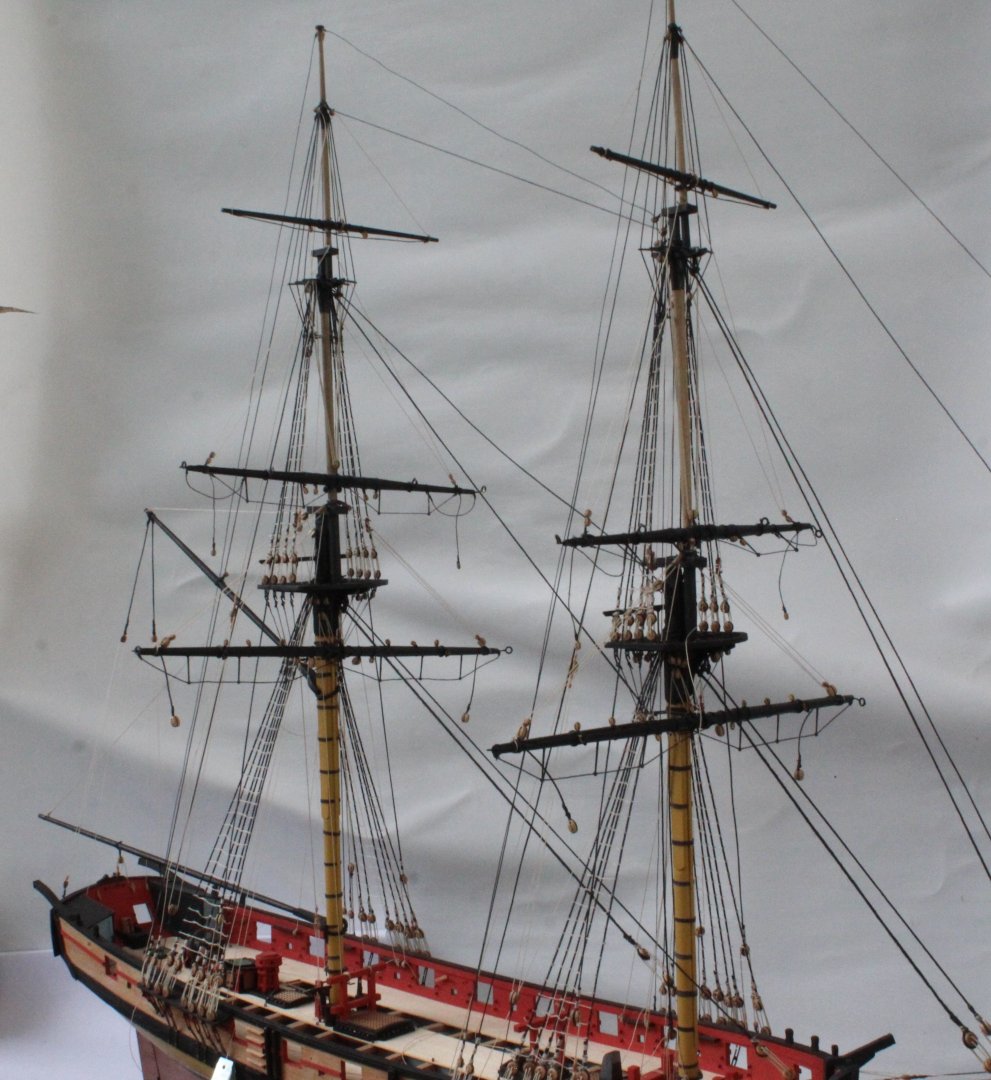
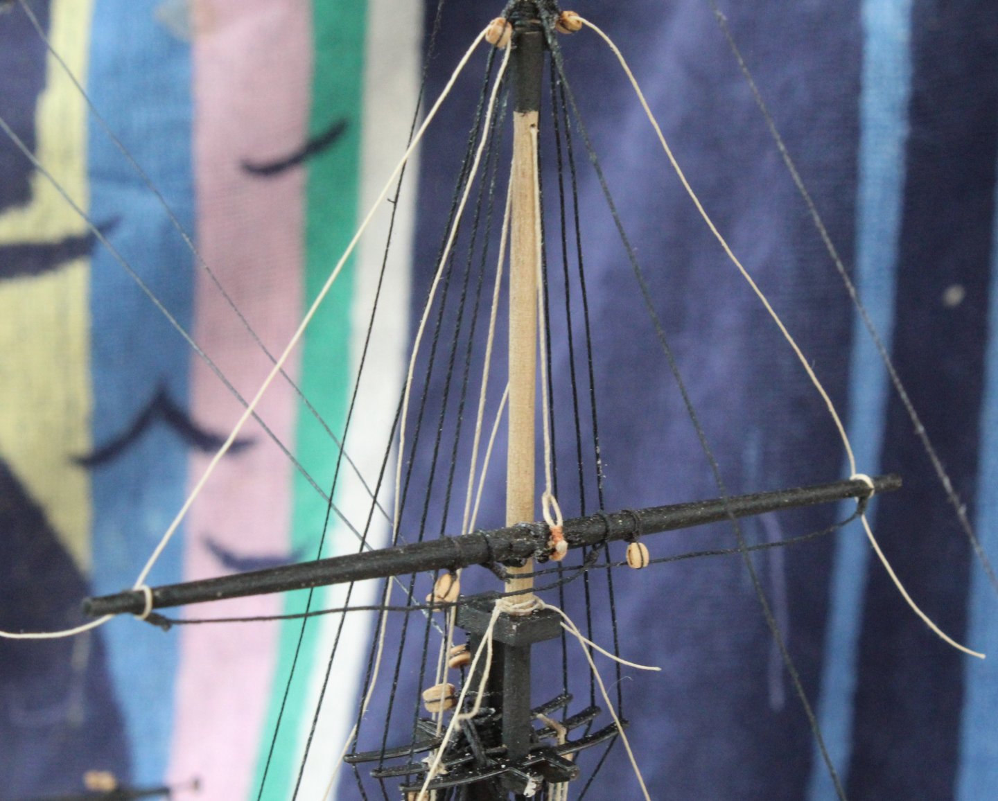
All the yard lifts have been rigged and belayed fore both the fore and main mast assemblies. For the most part I was able to set the lift tension so each yard was set at 90 degrees with the mast when belayed. The main yard lifts is shown in the photo below. The next two photo's shows the current build status. The lift rigging is difficult to see as the natural thread is not really visible when set against the white background. Clews, tacks and sheet rigging will be my next task which will take a few days to complete.
- 241 replies
-
- 8
-
-
-
- Vanguarrd Models
- Harpy
- (and 1 more)
-
I predict a riot when this kit is released
-
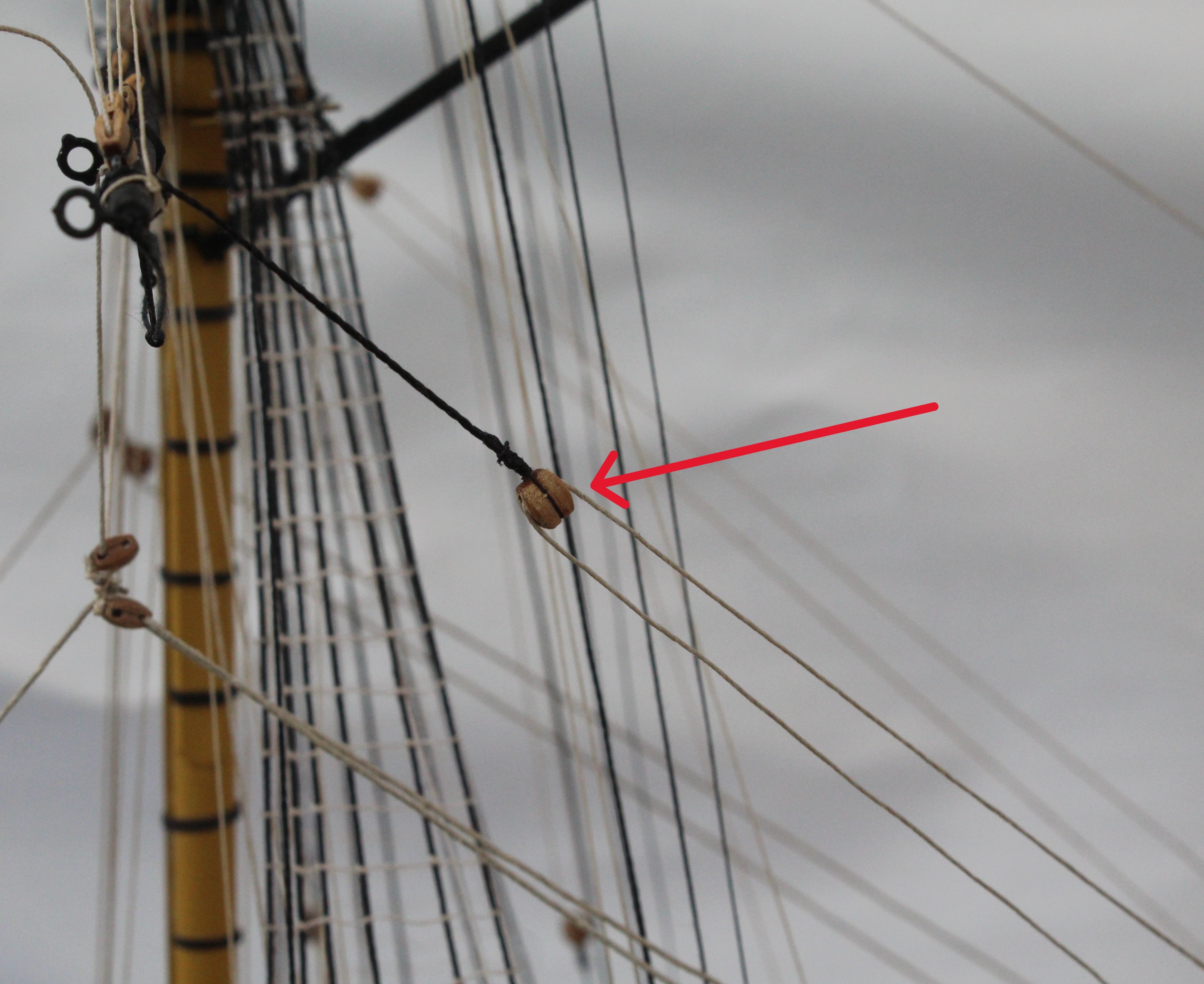
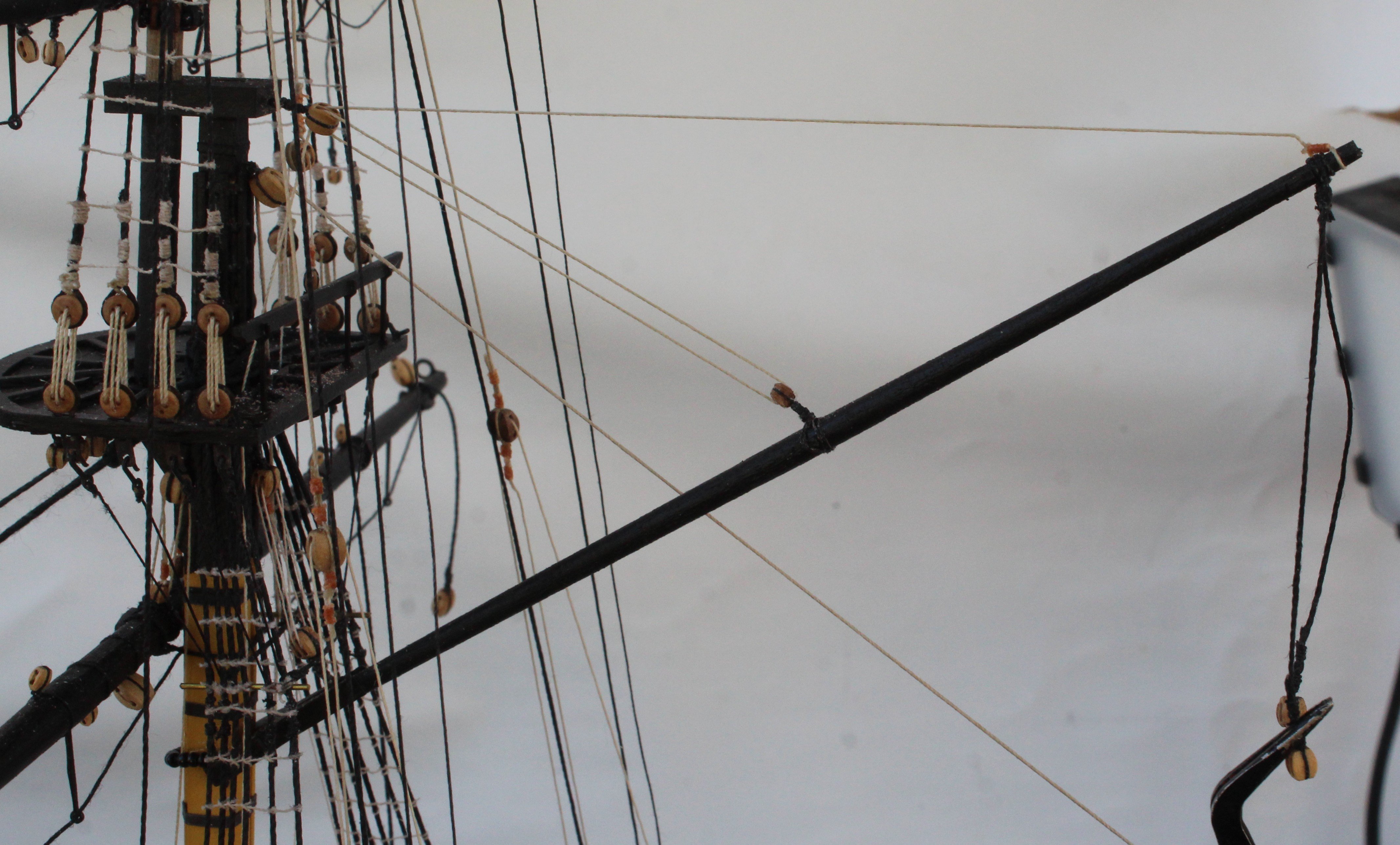
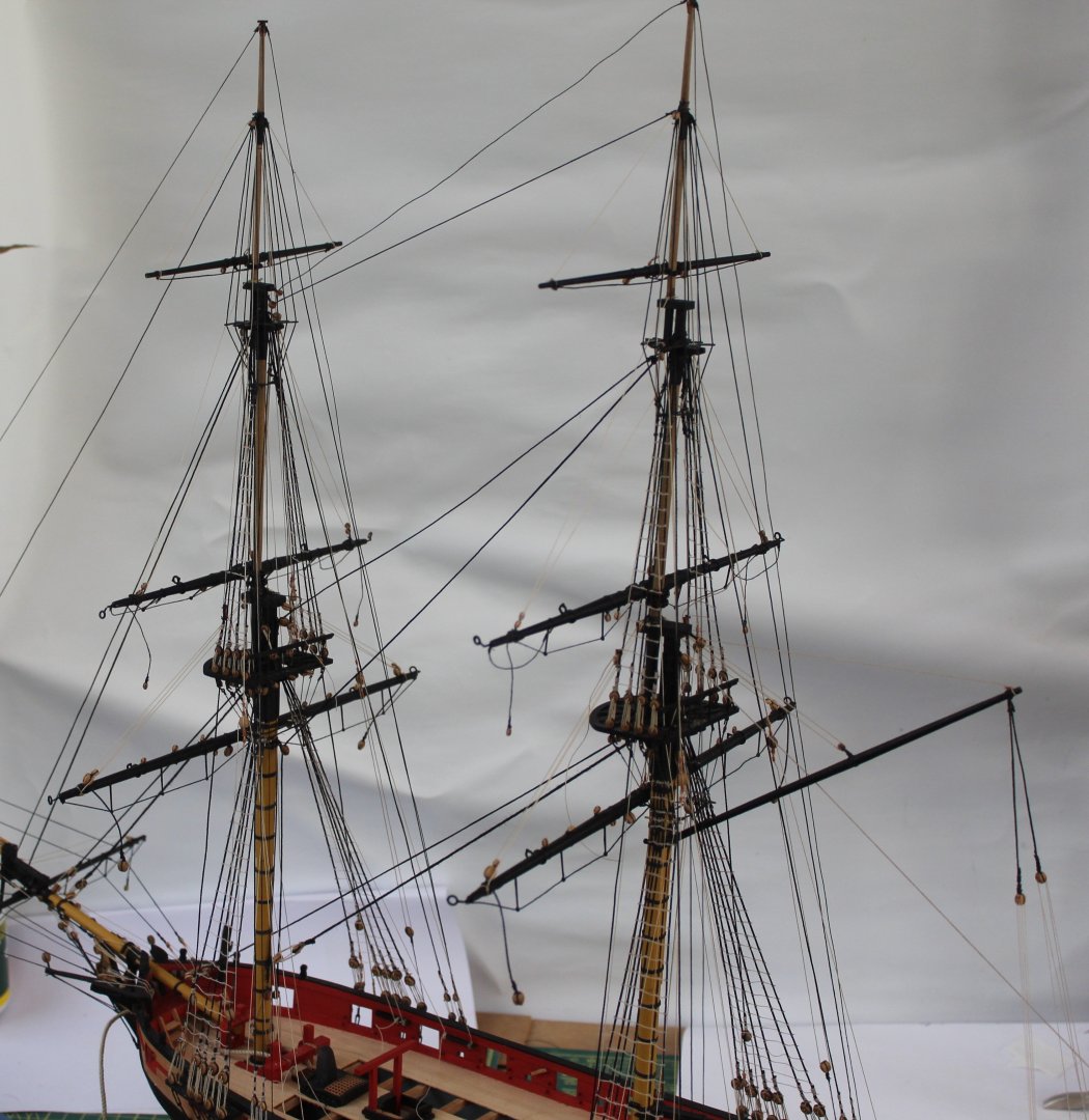
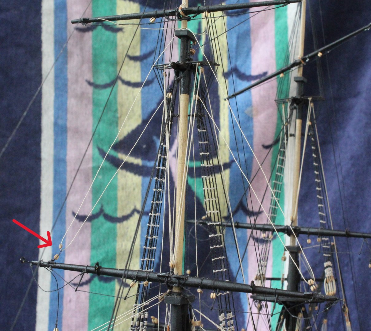
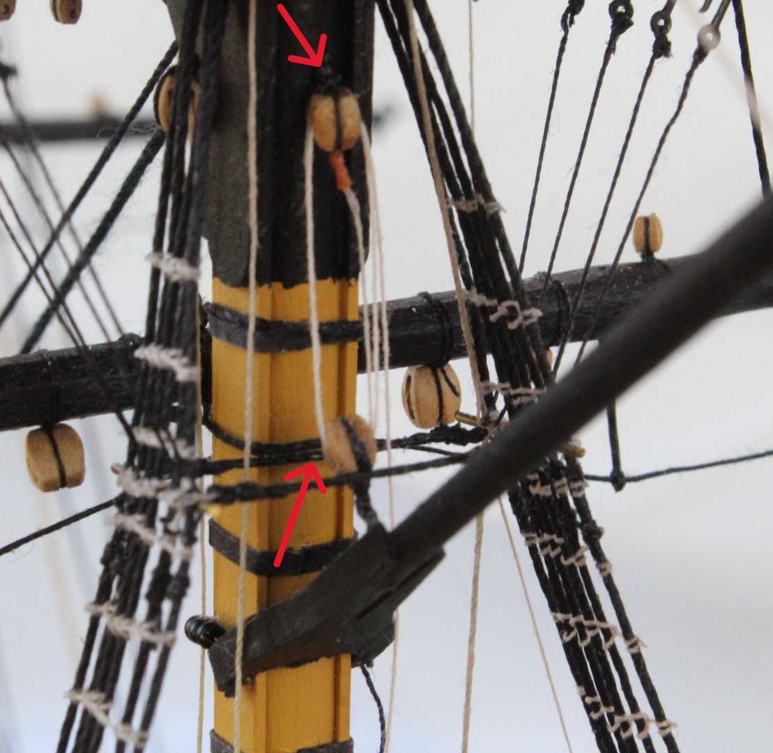
I have managed to sort out the issue with the damaged cleat and the vangs have now been belayed. The main and driver booms rigging can be seen in the next two photos. I have now started to rig the lifts for the fore yard fore topsail yard and fore topgallant yard. The next set of photos shows the fore yard lift rigging. The rigging will be belayed to pins on the inner bulwark pin rack which will be entertaining when setting the tension so the yard is set level. The next set of photos shows the fore topsail yard lifts. The rigging will be belayed to pins on the inner bulwark pin rack, next to the foreyard lift belaying pin. The arrow in the first photo shows a block which has separated from the seizing. The arrows in the third photo shows the lift rigging. The final photo shows the fore topgallant yard lift. The rigging will be belayed to cleats located on the back of the topsail shroud rigging.


- 241 replies
-
- 7
-
-
- Vanguarrd Models
- Harpy
- (and 1 more)
-
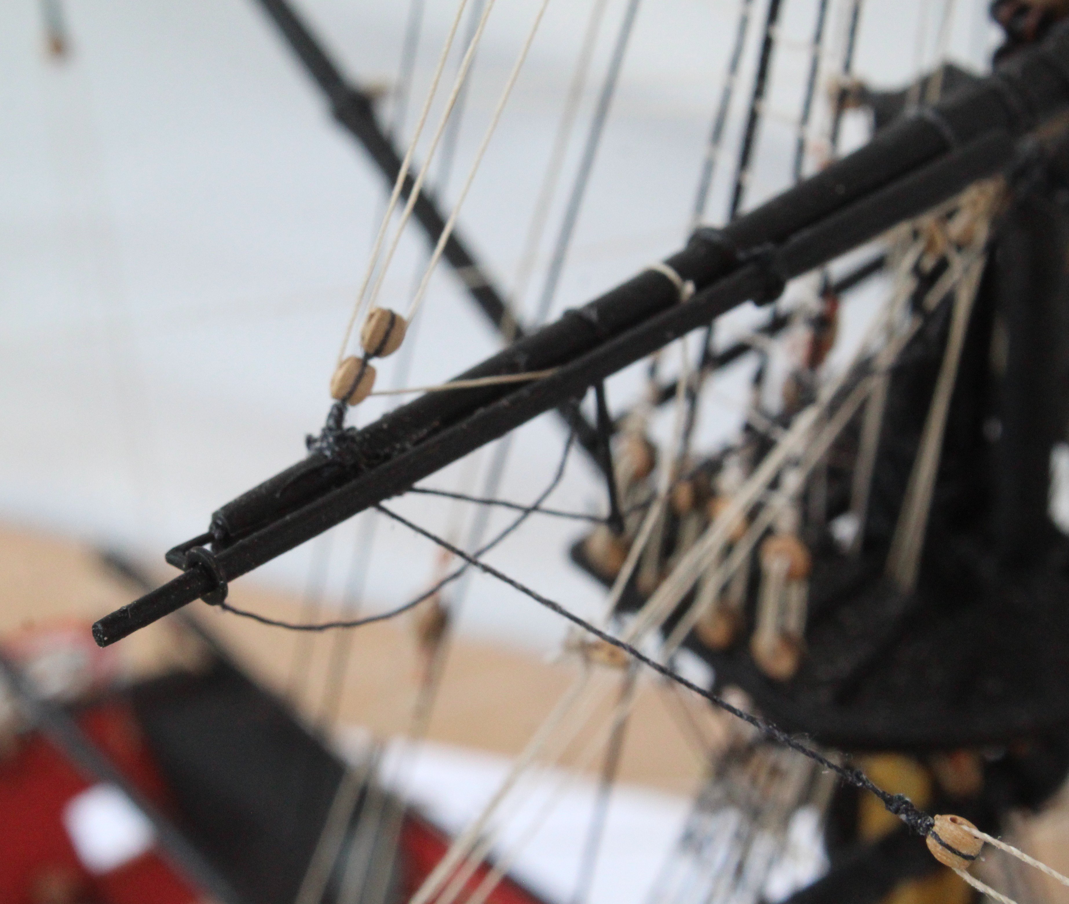
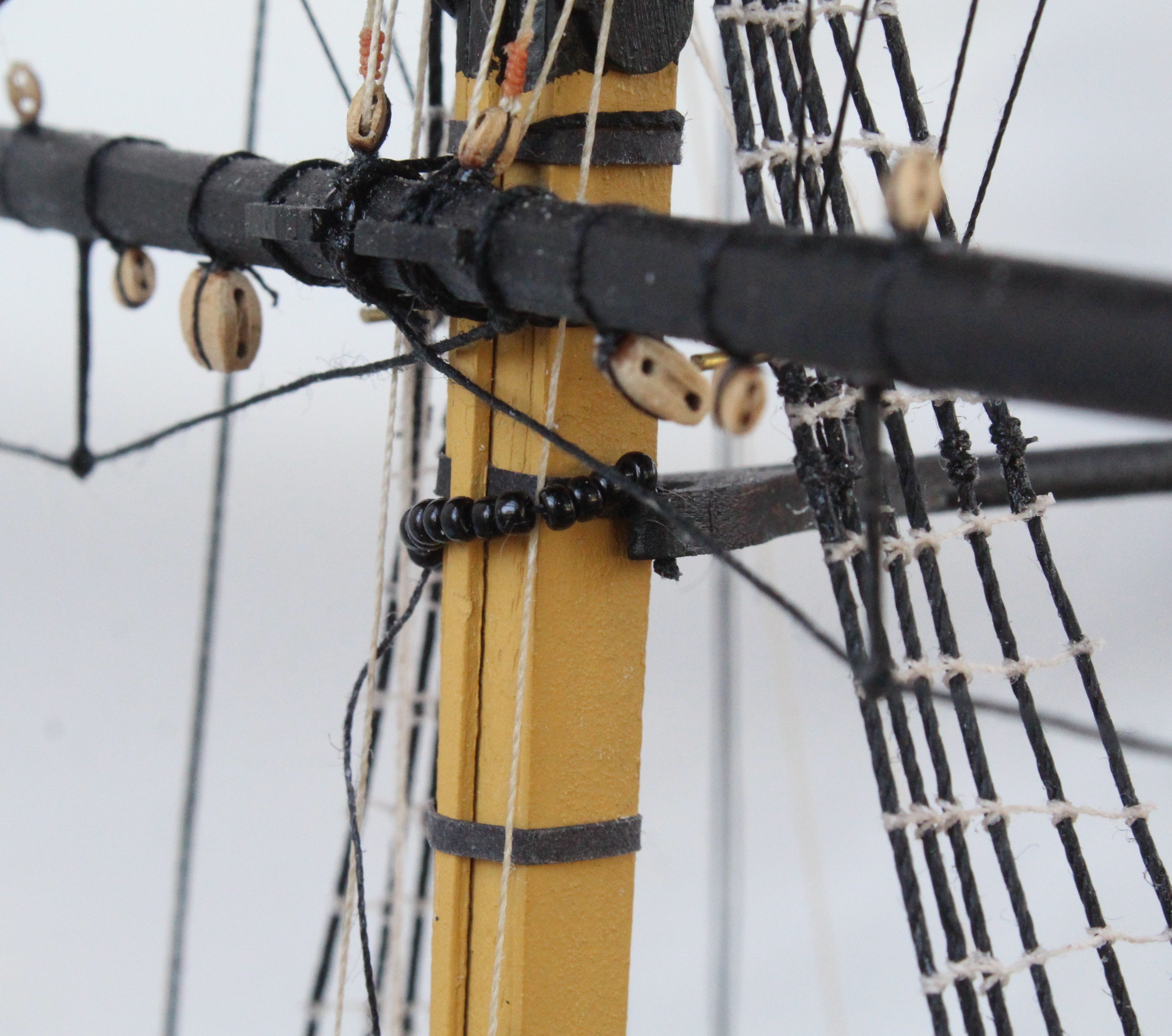
Today I have been installing the driver boom. The first photo below shows the WIP when adding the parral beads. The next photo shows the inter-block rigging for the driver boom tye. The next section of the rigging has been added as shown on the next photo. I am using pliers to add tension to the vangs, whilst the rigging is belayed. The next photo shows a double block reeved. The inter-block rigging for the two vangs have been added, as shown below. I am having a problem belaying the vang rigging as the cleats are located very close to the side cabins making it very difficult to tie off. I have also hit a snag as can be seen in the photo below as one cleat has seared off. I am not sure what I am going to so at the moment. Grandkid duties tomorrow so I have a couple of days to consider my options.


- 241 replies
-
- 5
-
-
- Vanguarrd Models
- Harpy
- (and 1 more)
-
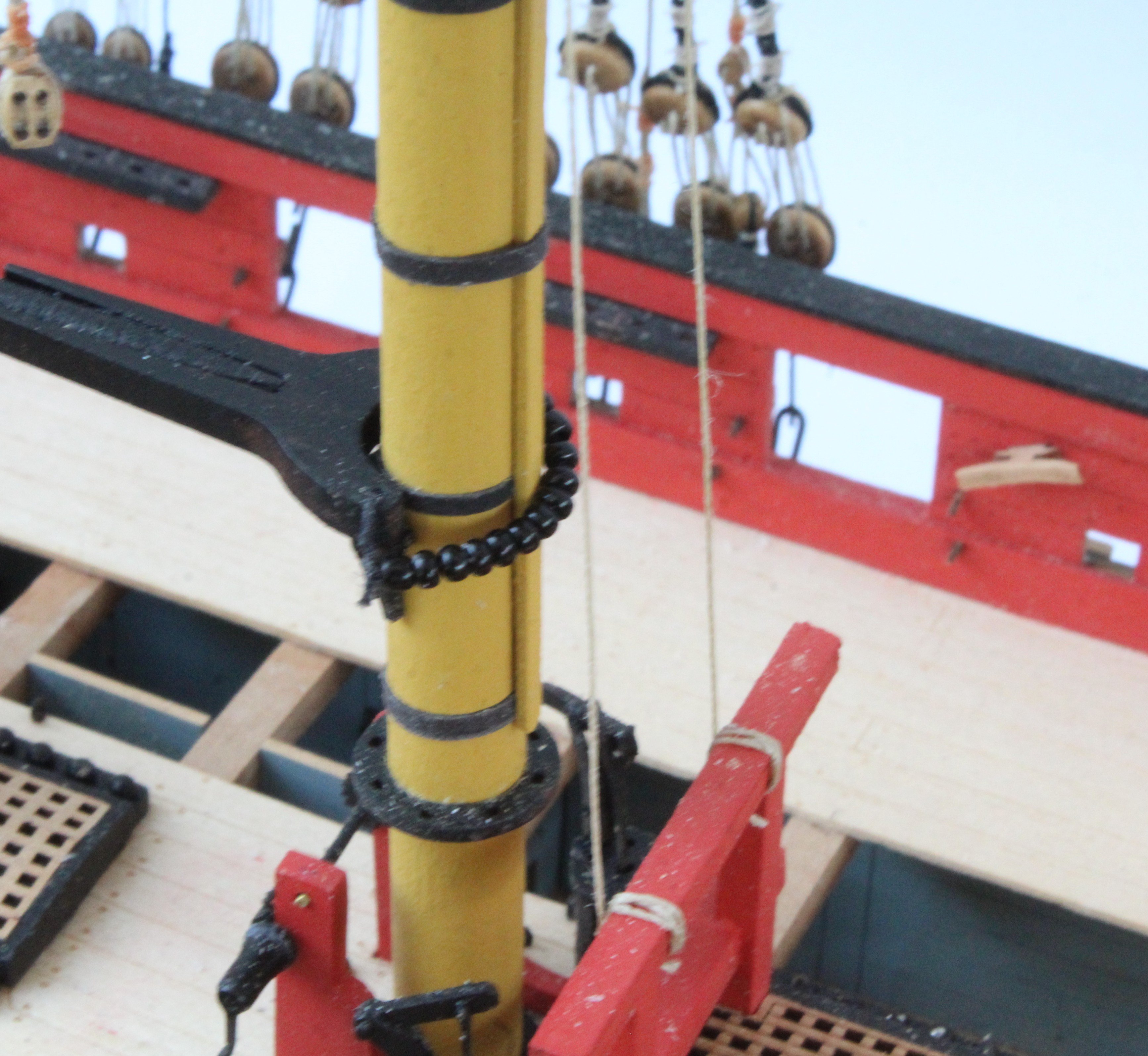
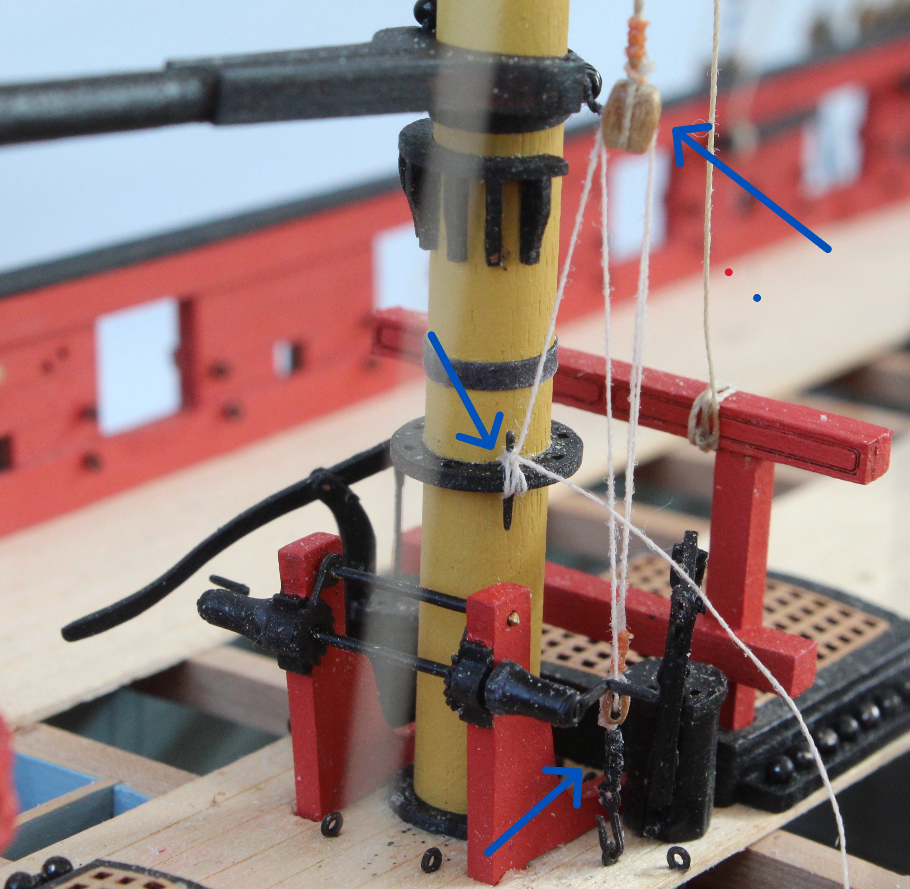
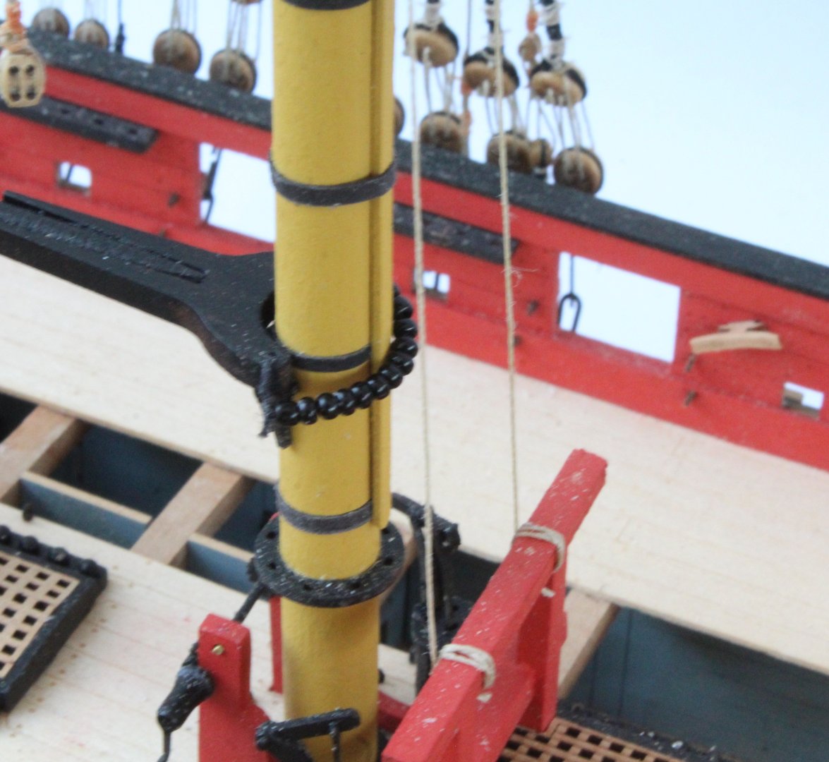
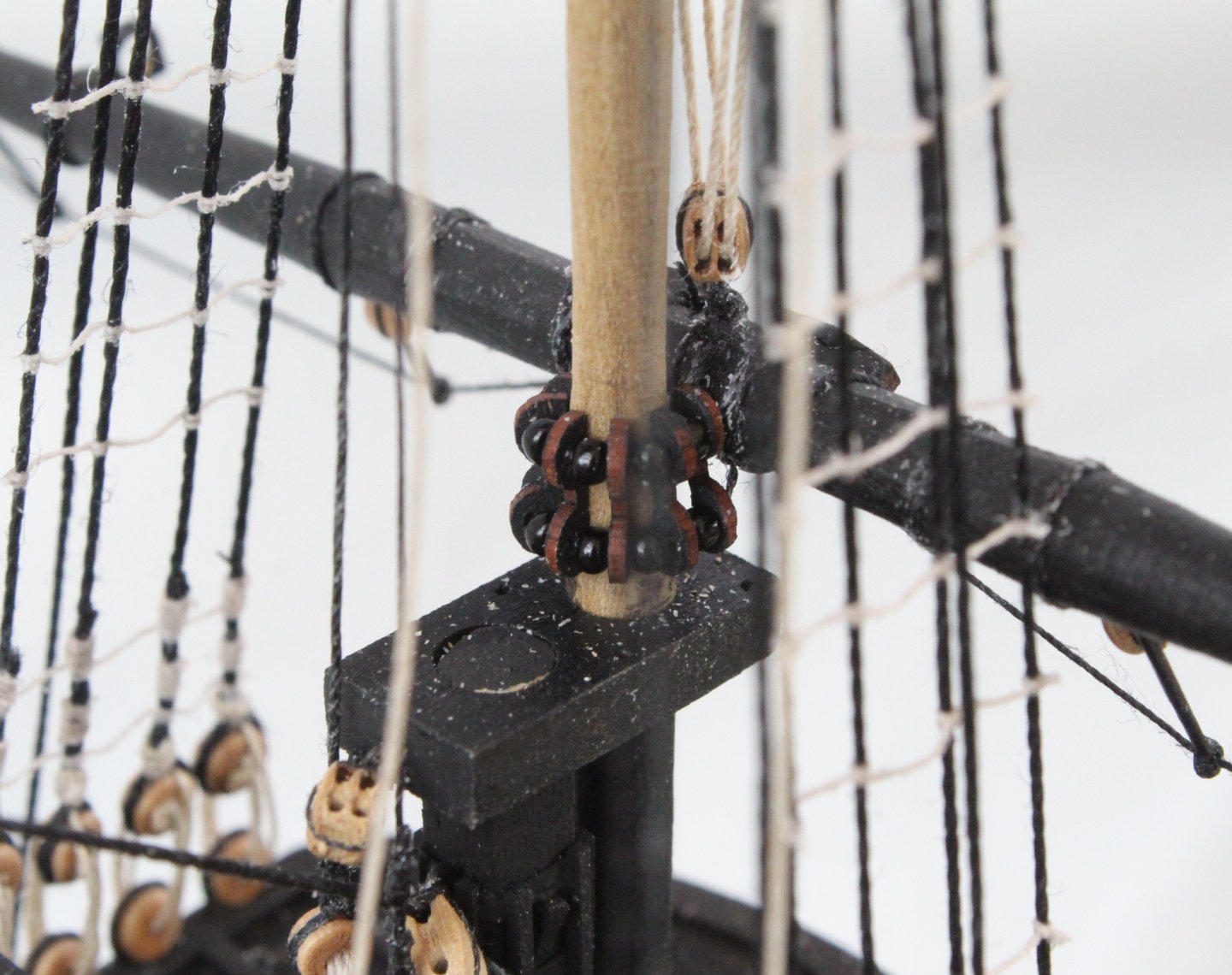
Today the Main Boom was installed. The first task was to secure the boom to the main mast with parral beads. Next a length of thread was added to the end of the boom, as can be seen in the next photo. This thread was then reeved through a block secured to the back of the main mast, as shown below. The end of the boom was then belayed using a double block arrangement, as shown below. Finally the thread that had been reeved through the main mast block was belayed to the deck via a double block arrangement, as shown below. Finally a photo of the completed installation. Next up will be the installation of the driver boom. Once that is done I will move on to rigging all the yard lifts, clews, sheets and tacks. Once they have been rigged the final task will be to rig all the yard braces and bowlines.

- 241 replies
-
- 8
-
-
- Vanguarrd Models
- Harpy
- (and 1 more)
-
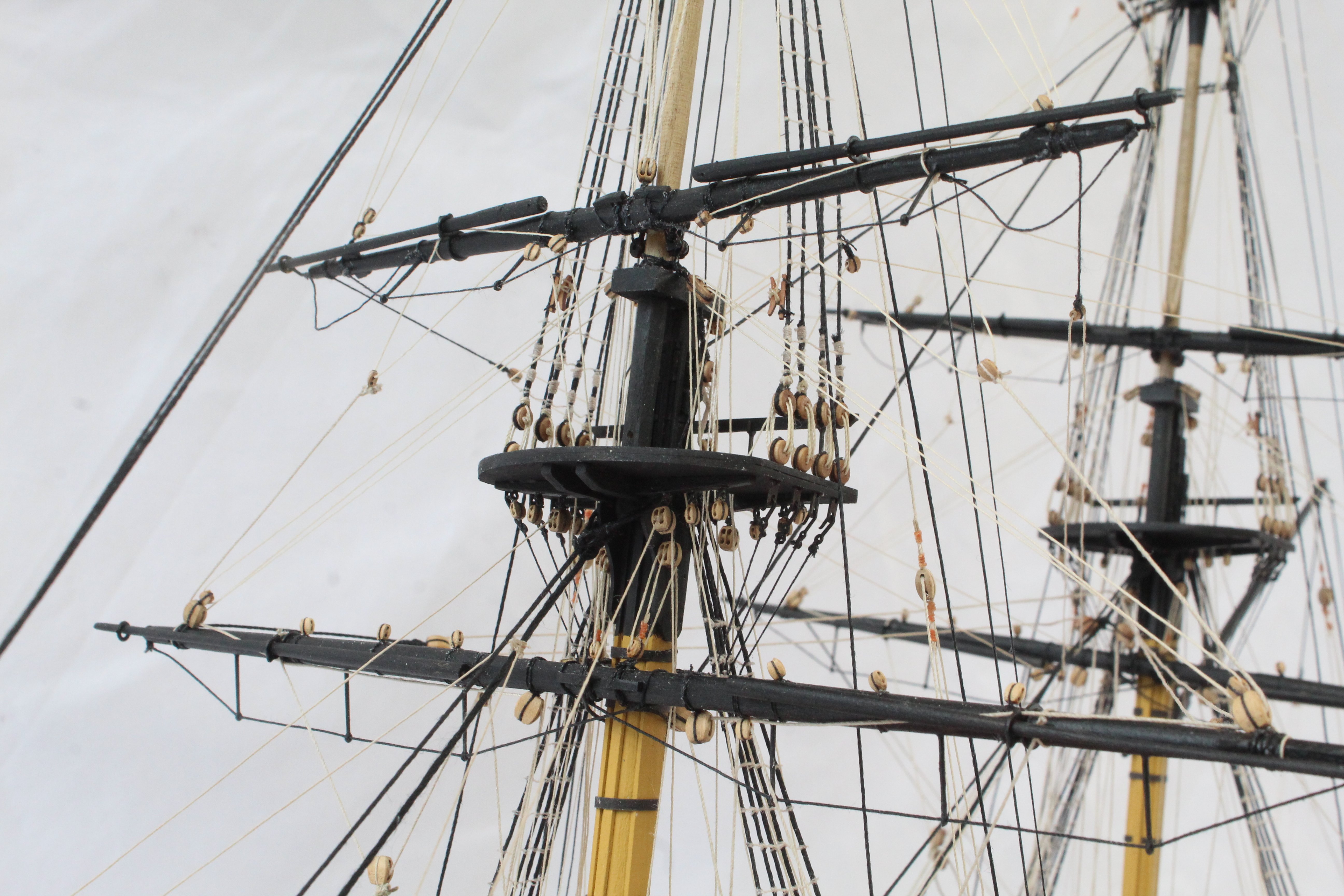
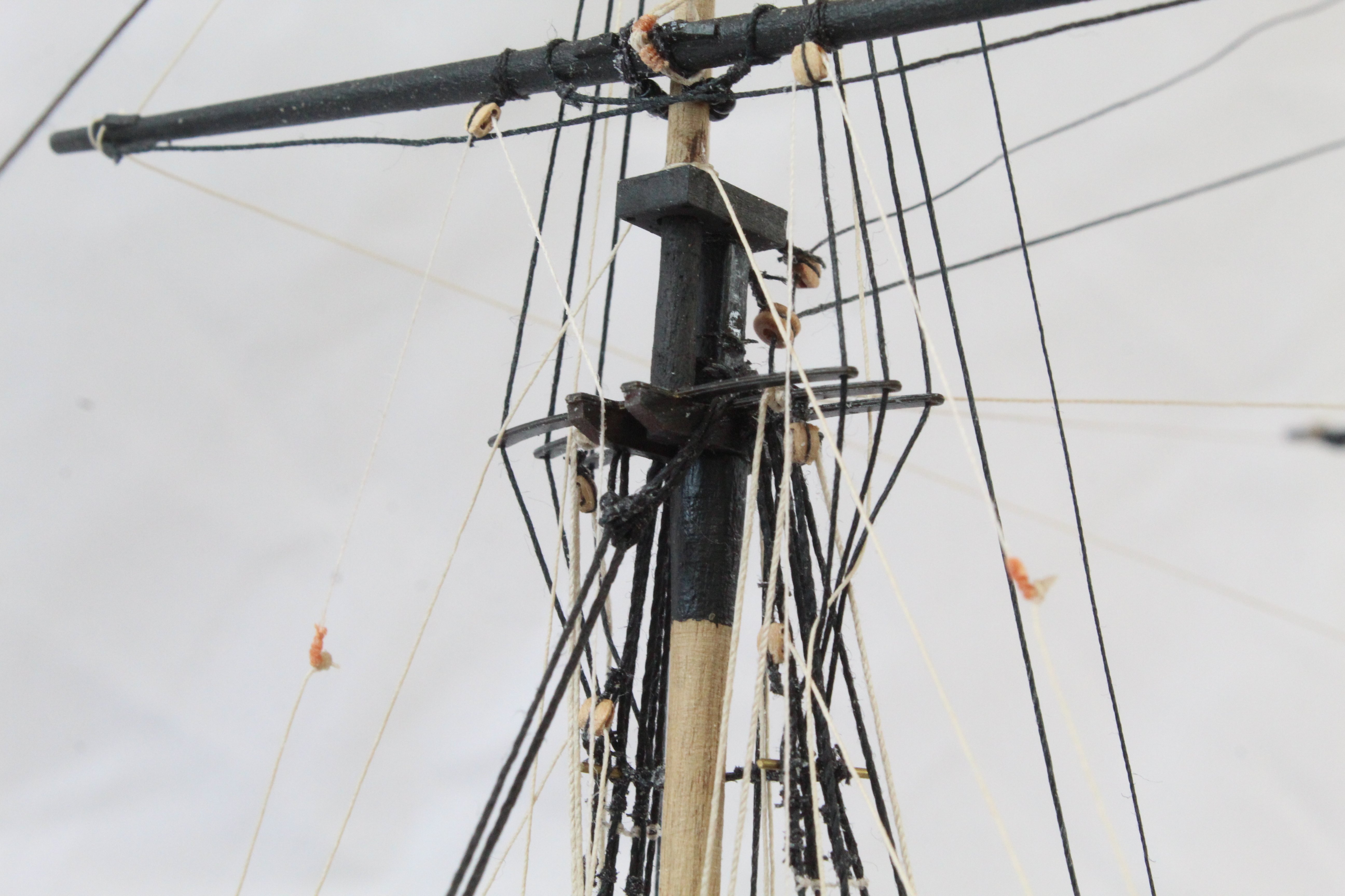
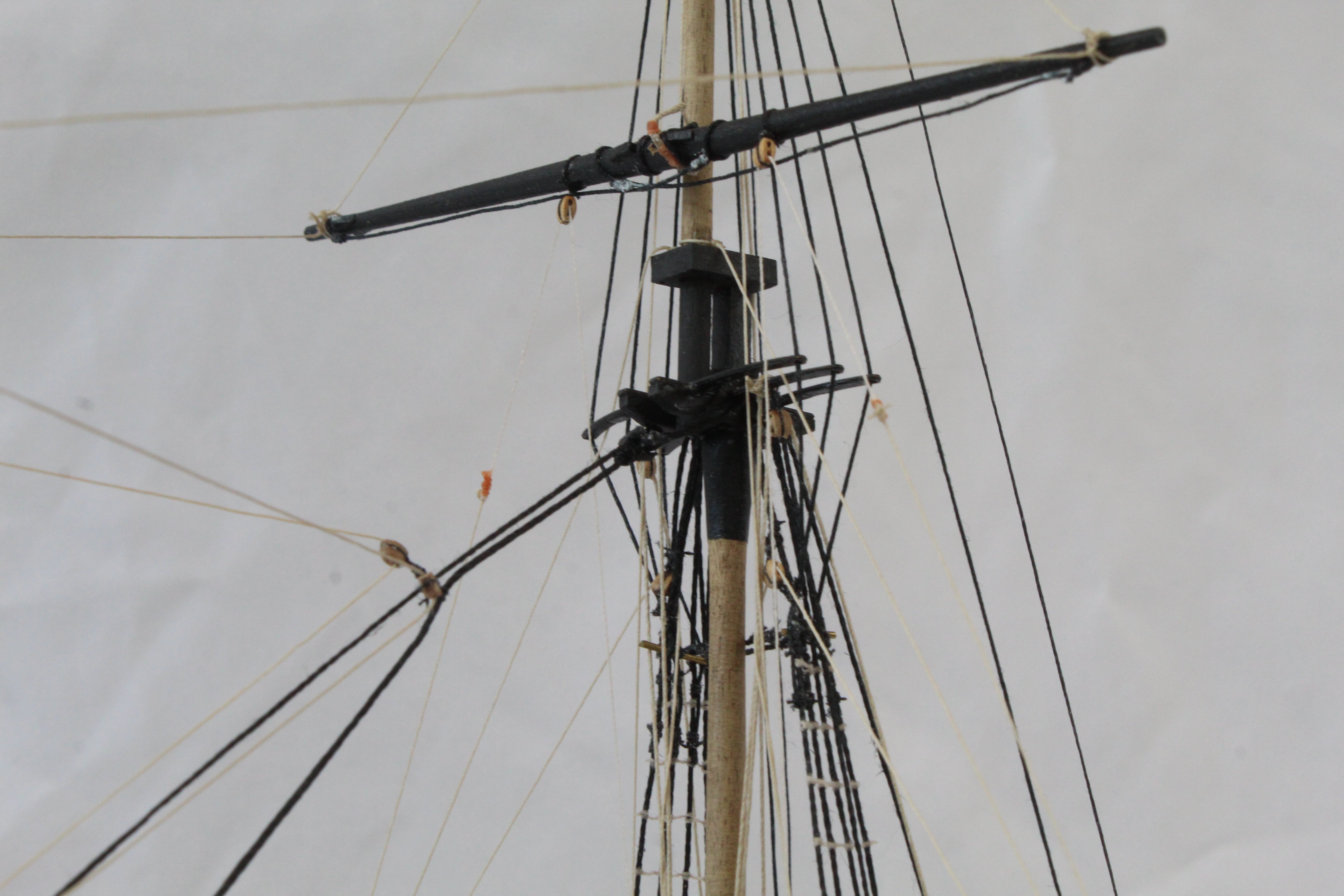
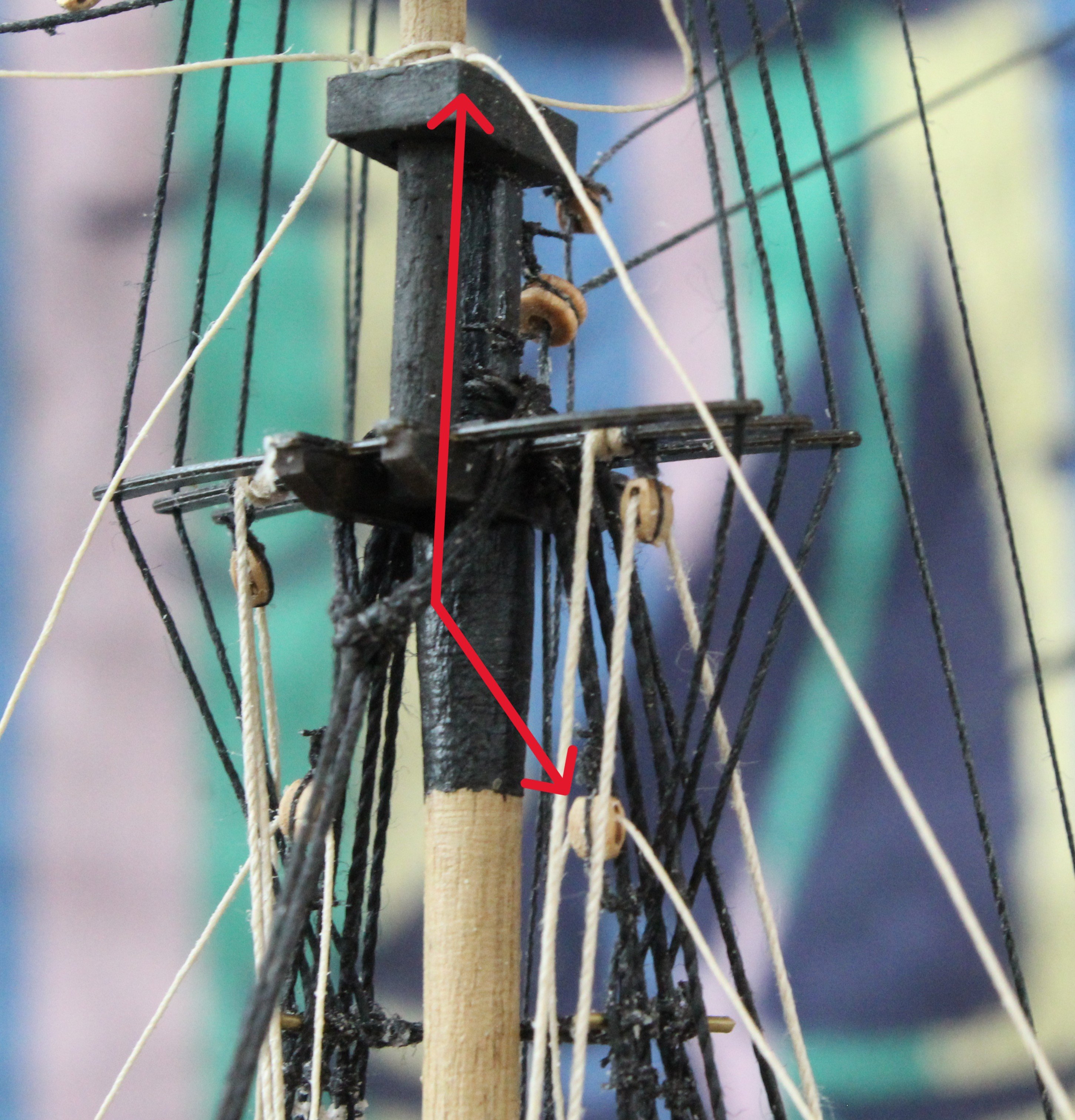
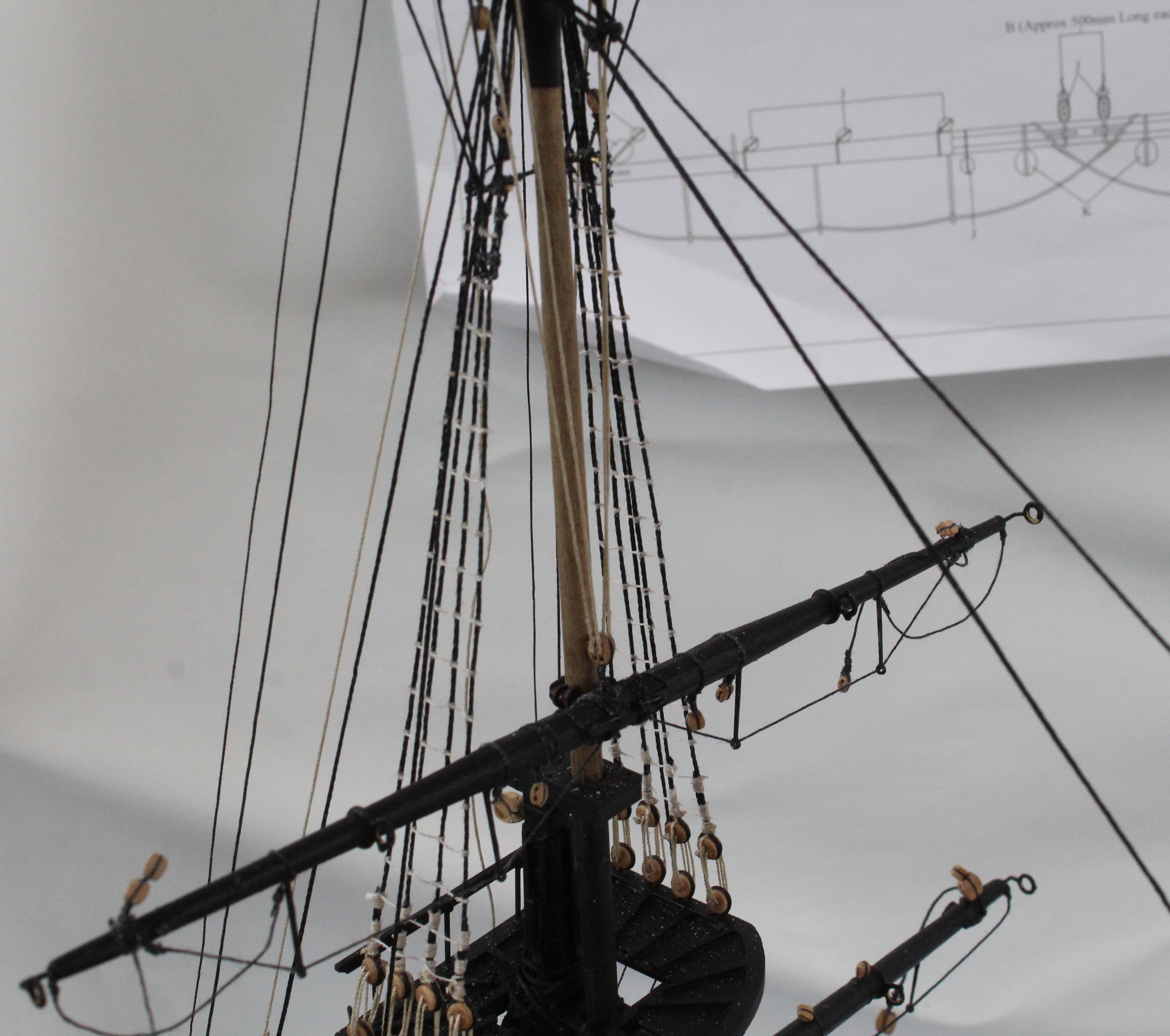
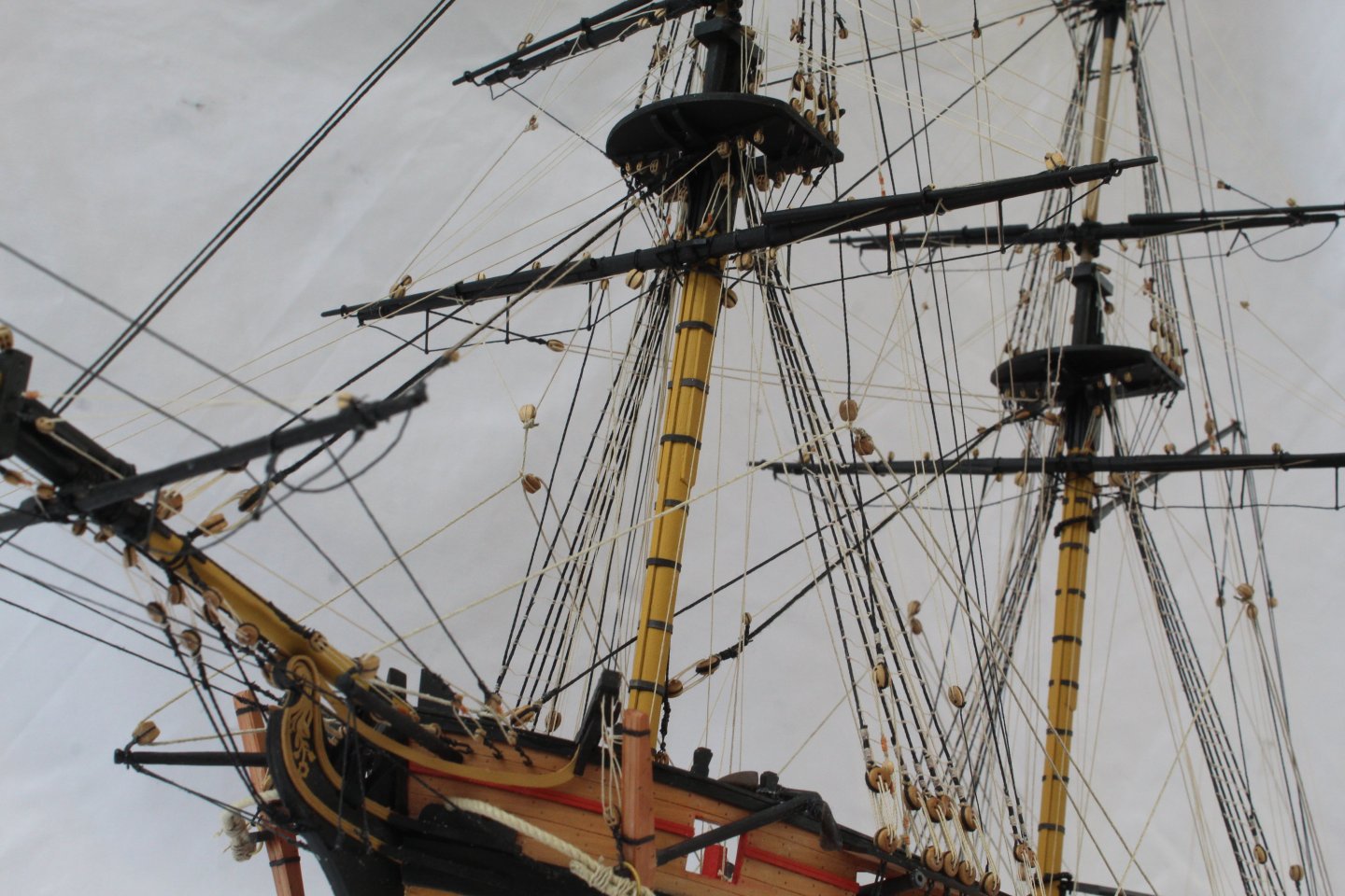
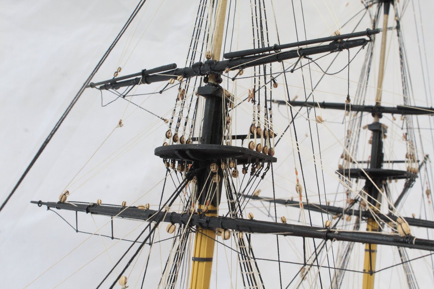
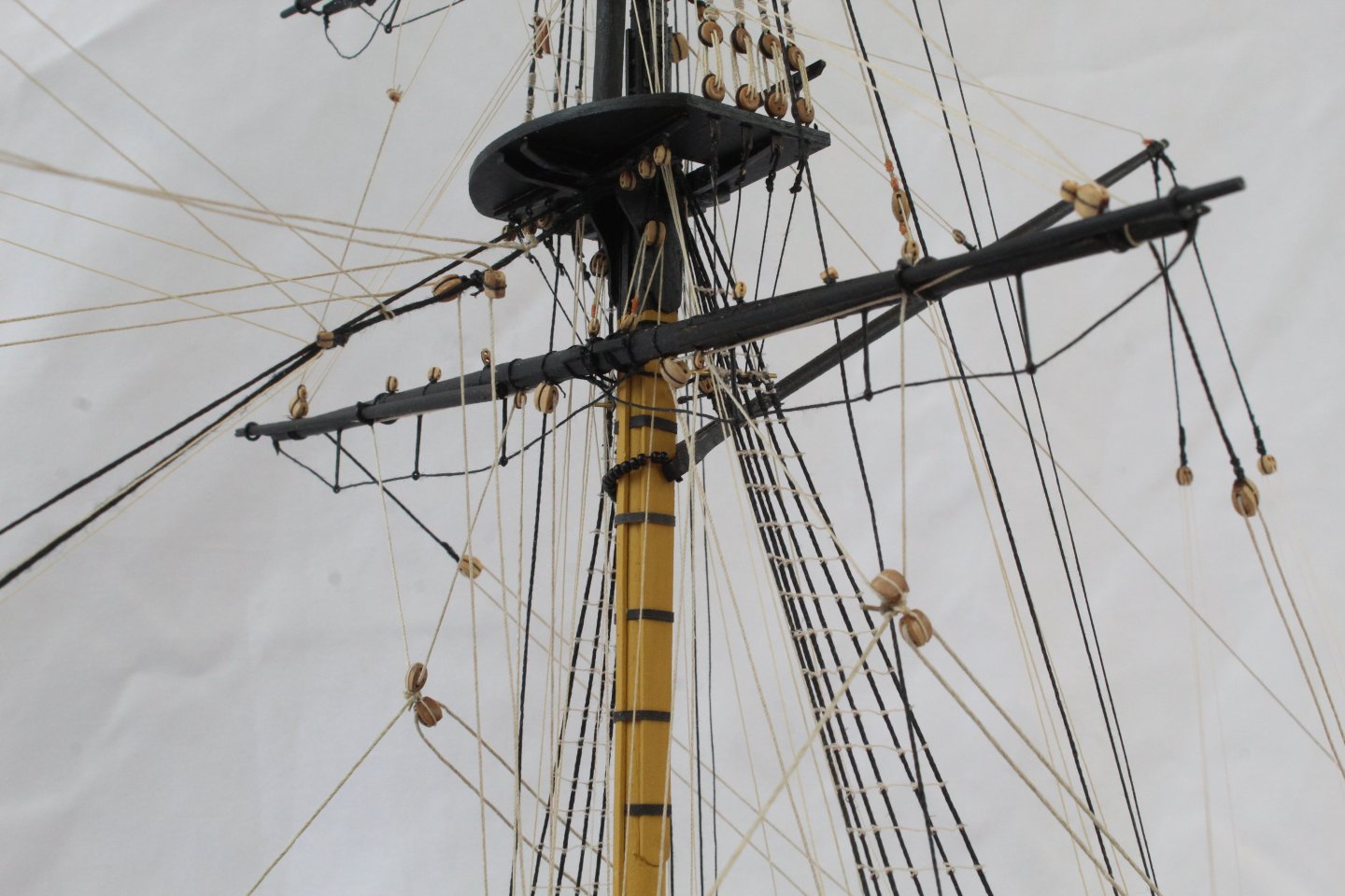
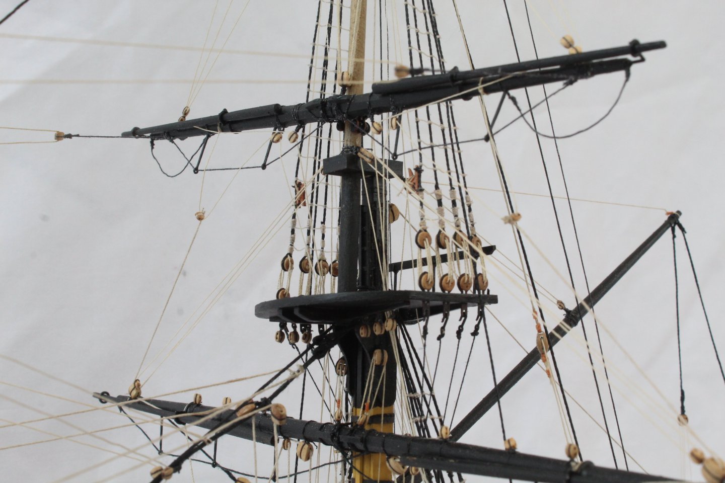
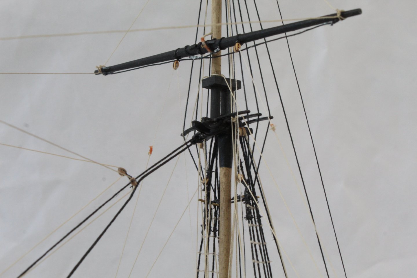
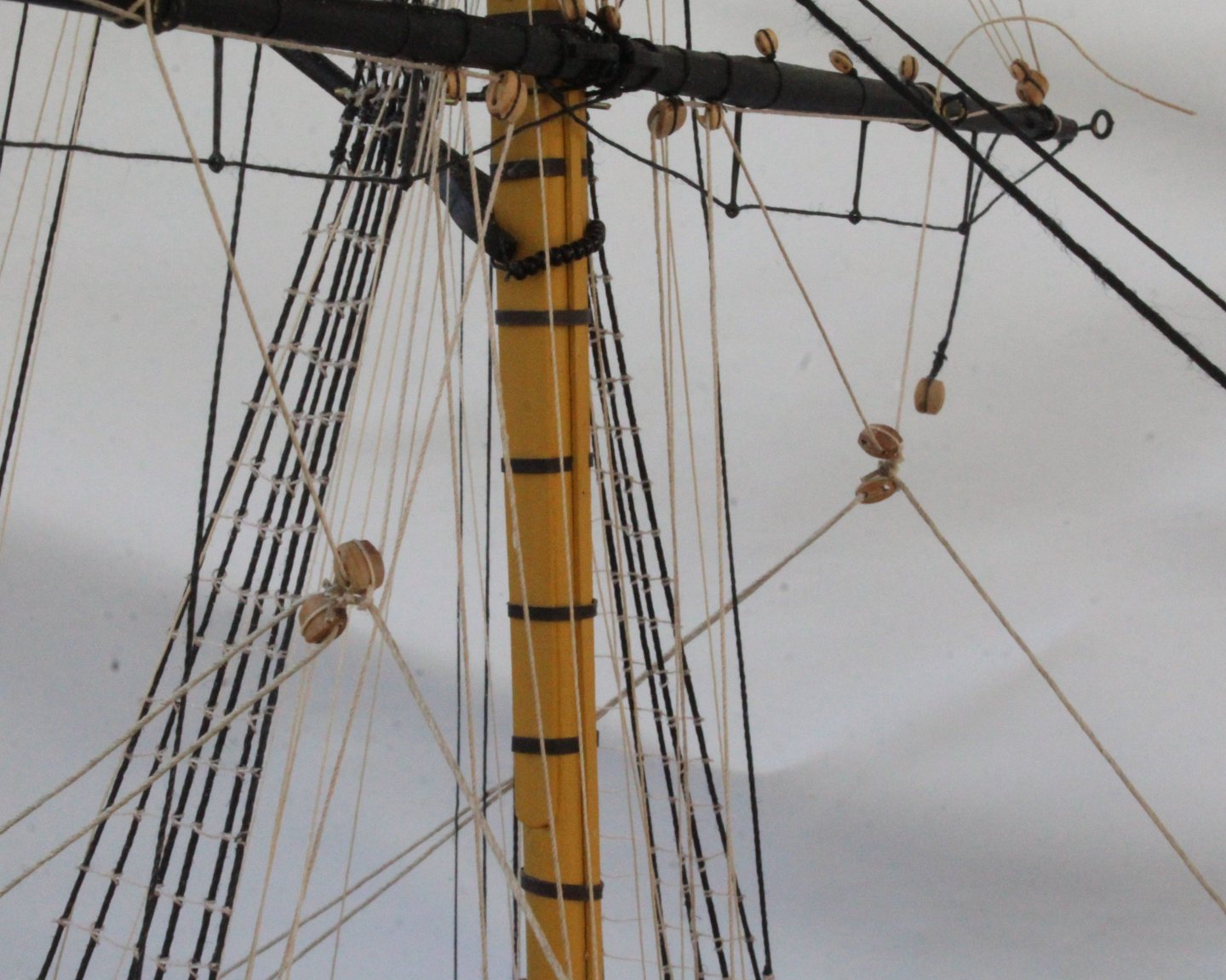
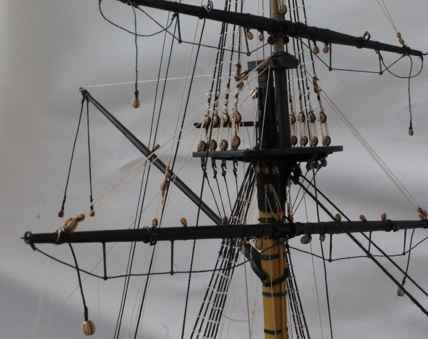
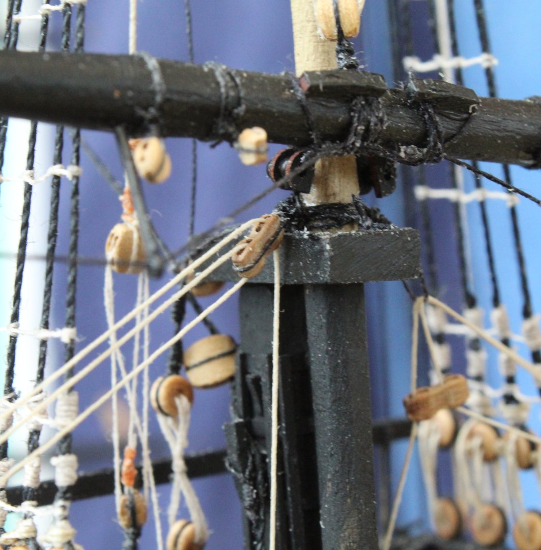
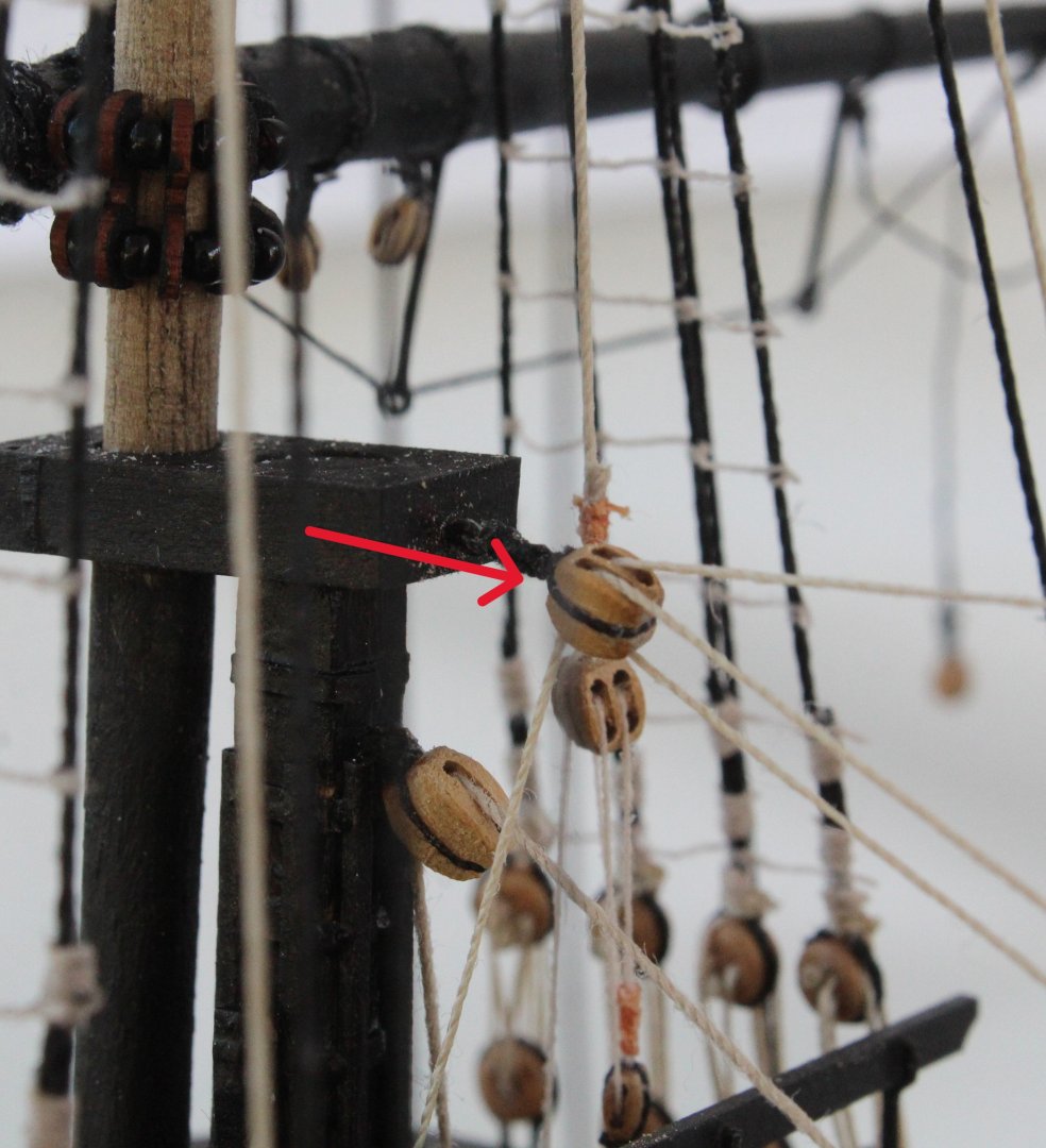
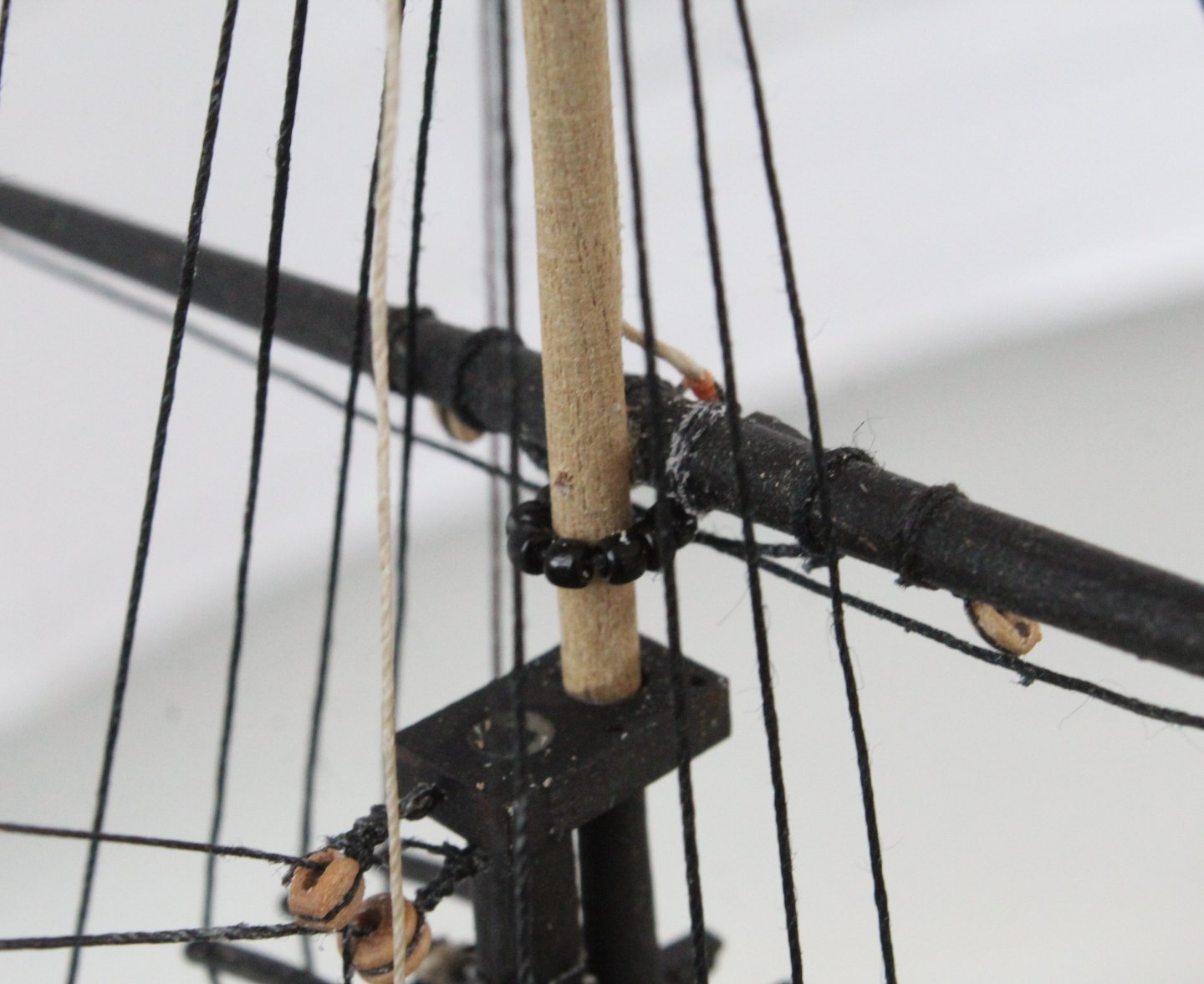
The main and foremast topsail and top gallant yards have now been added complete with tyes and lifts rigged. Here is a picture of the current state of the build. Now a picture showing the fore topsail yard with the parral beads in place. The parrel beads around the fore topgallant yard is shown in the next picture. Next is a photo of the topsail yard lfts which are now fully rigged and belayed. The final two photos show the lifts for the main topgallant yard, noting I have not belayed which will be via a double block arrangement, with the lower block hooked to an eyebolt on the lower platform.


- 241 replies
-
- 7
-
-
- Vanguarrd Models
- Harpy
- (and 1 more)
-
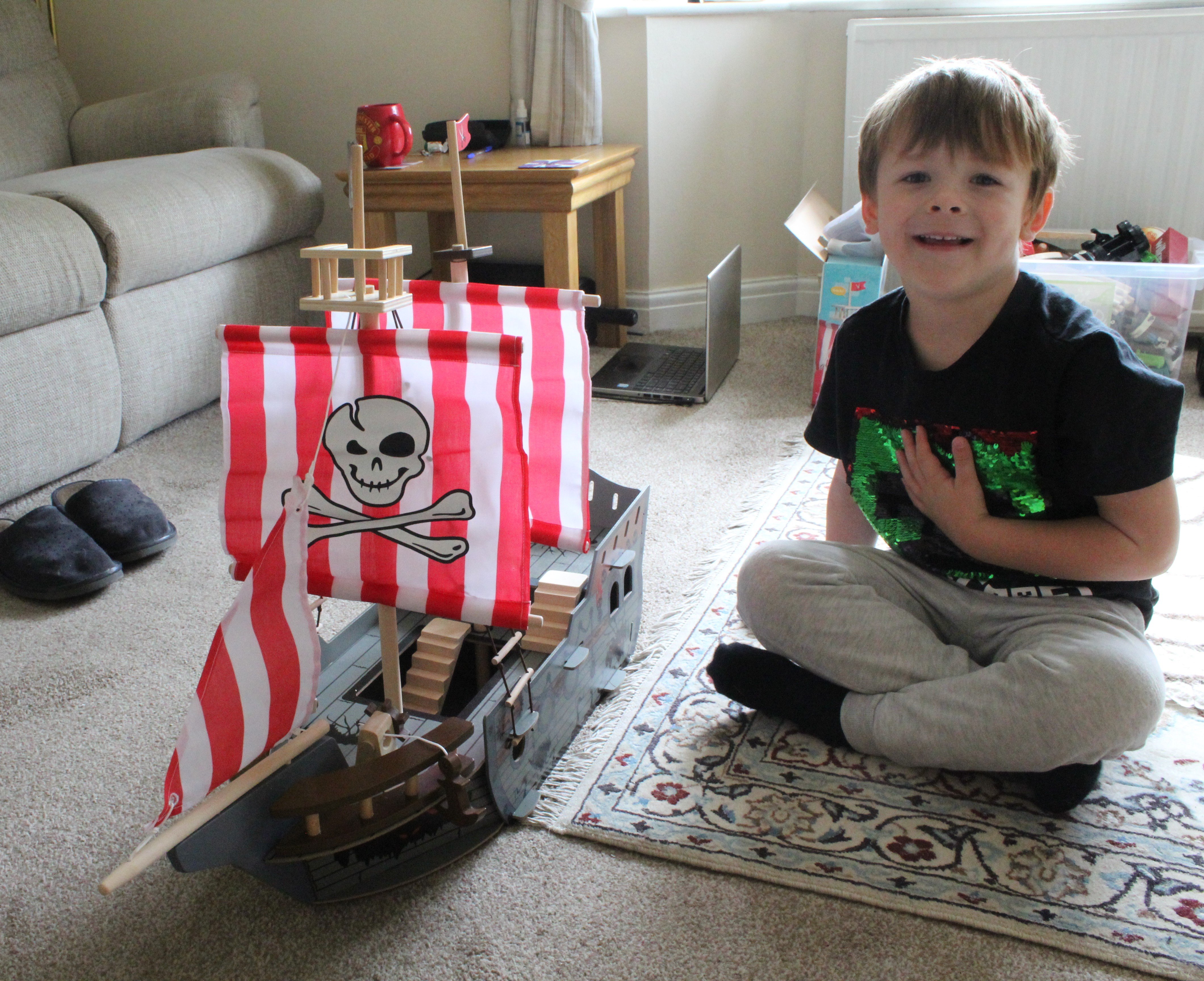
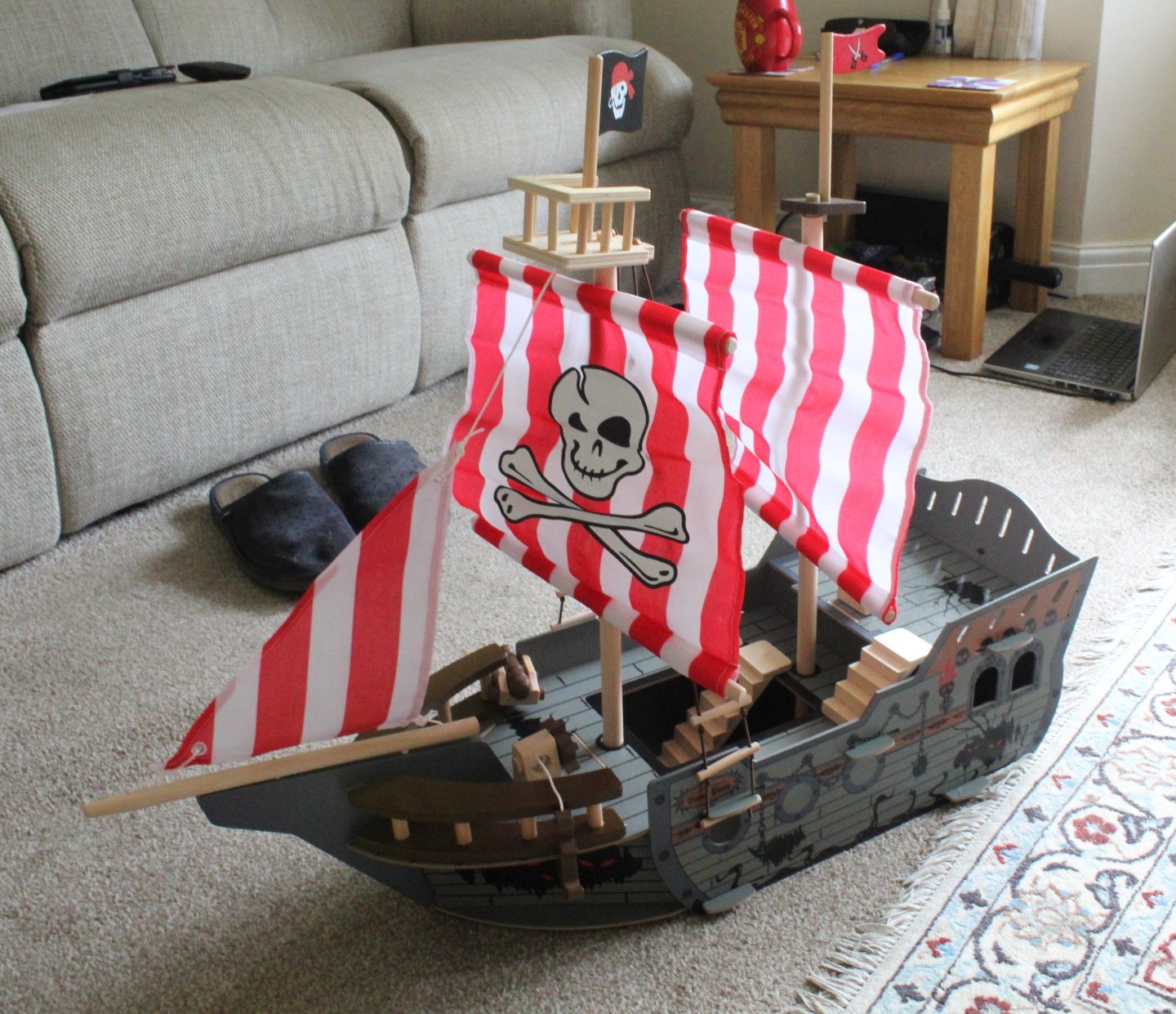
Shiver Me Timbers Todays task was to build a swashbuckling pirate ship ready for a battle on the seas. The kit came with 29 pieces and is suitable for 3+ although the kit did say "Adult Assembly Required". As with most of the kits I build I did have to strip it down and start again as I did miss adding a vital part. I did have have a willing helper and after 40 minutes of hard work the kit was completed.

- 241 replies
-
- 12
-
-

-
- Vanguarrd Models
- Harpy
- (and 1 more)
-
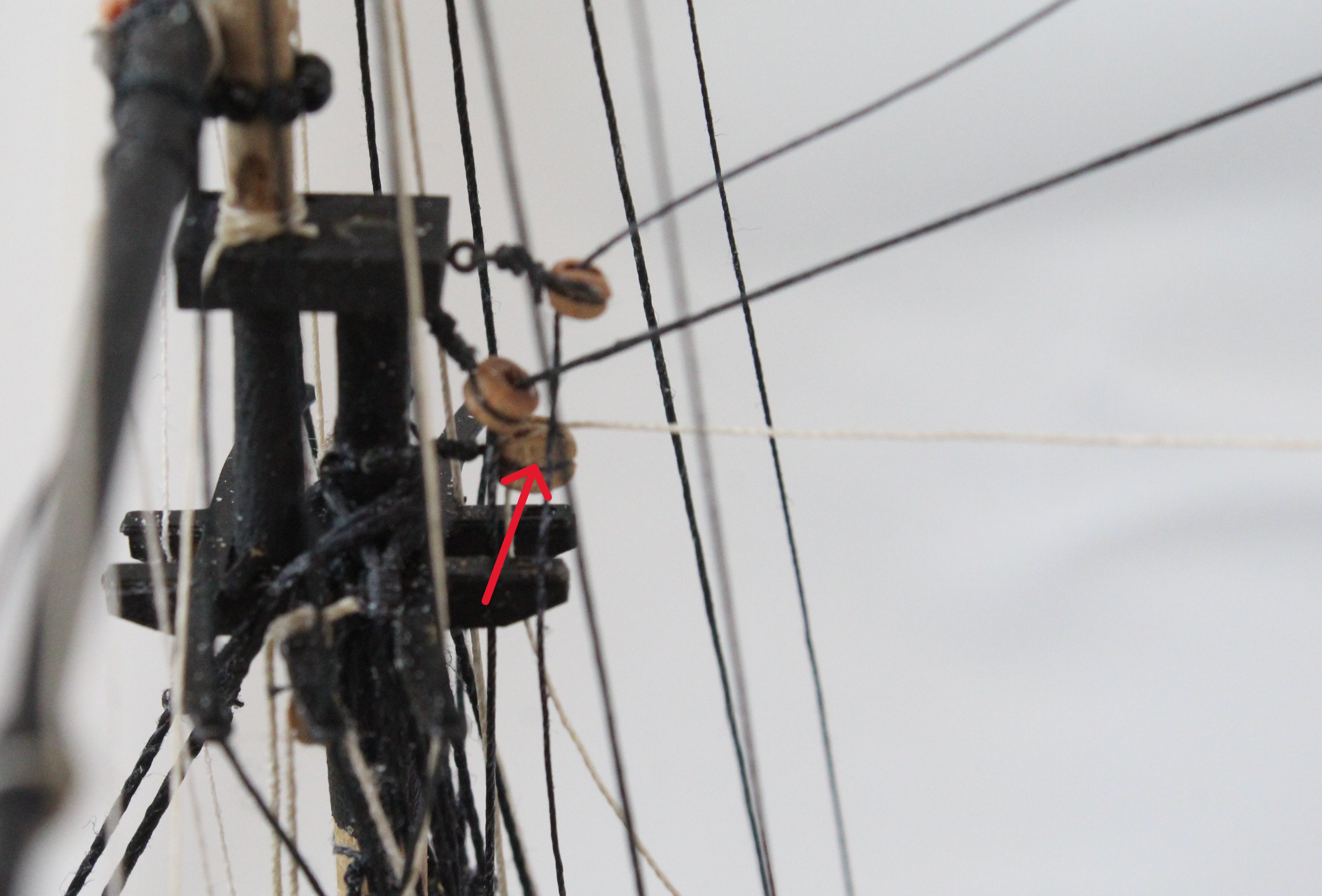
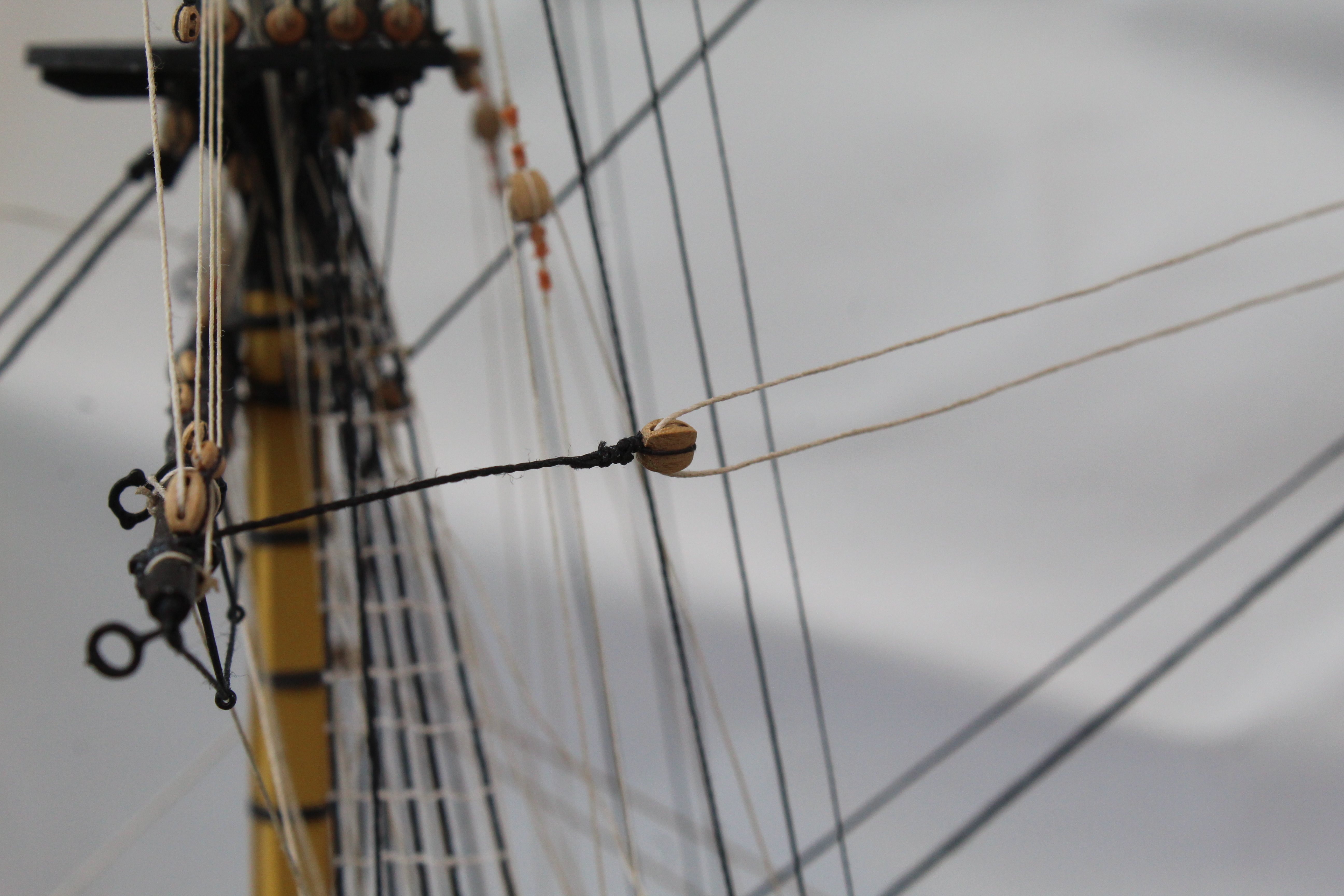
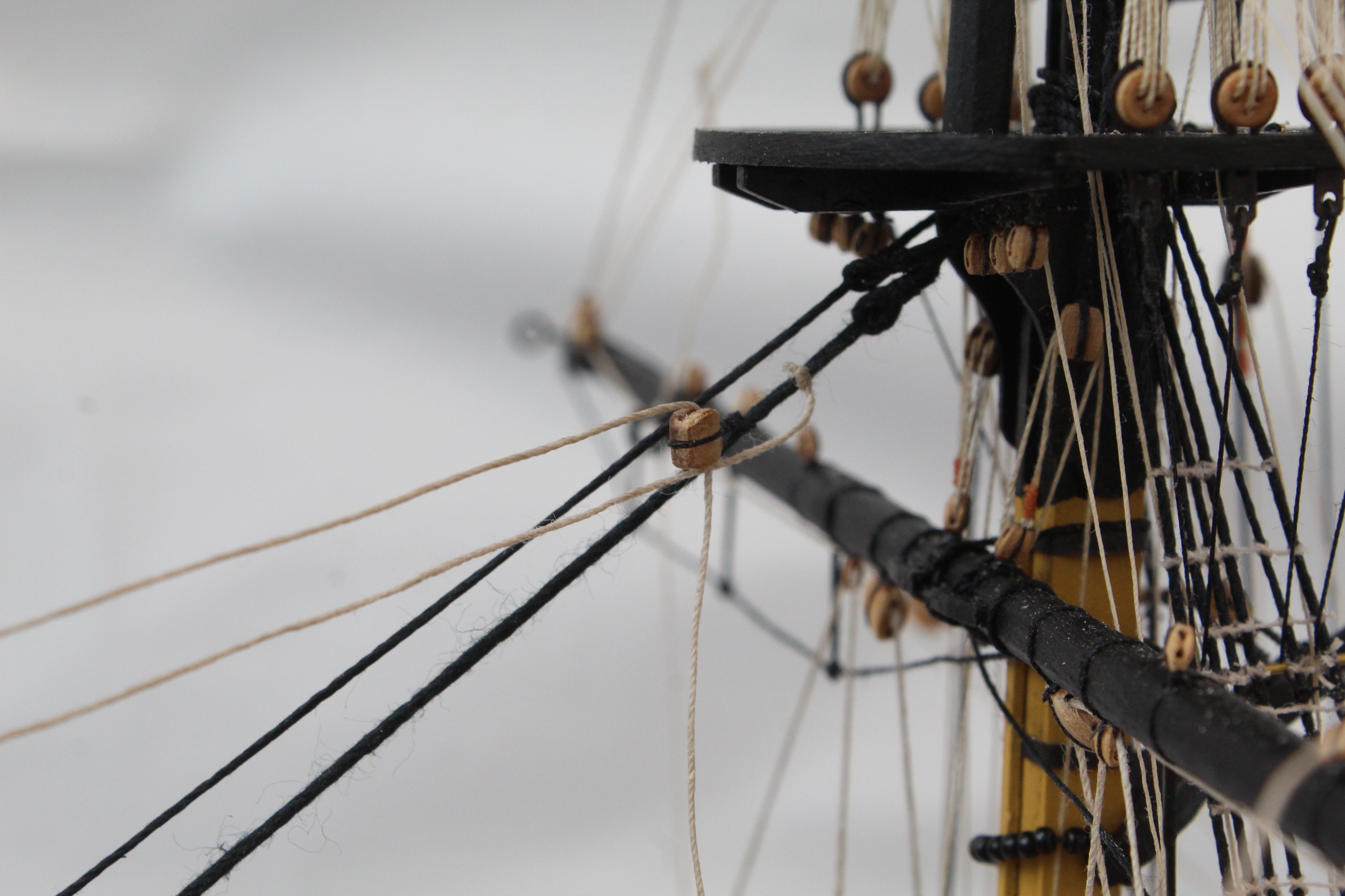
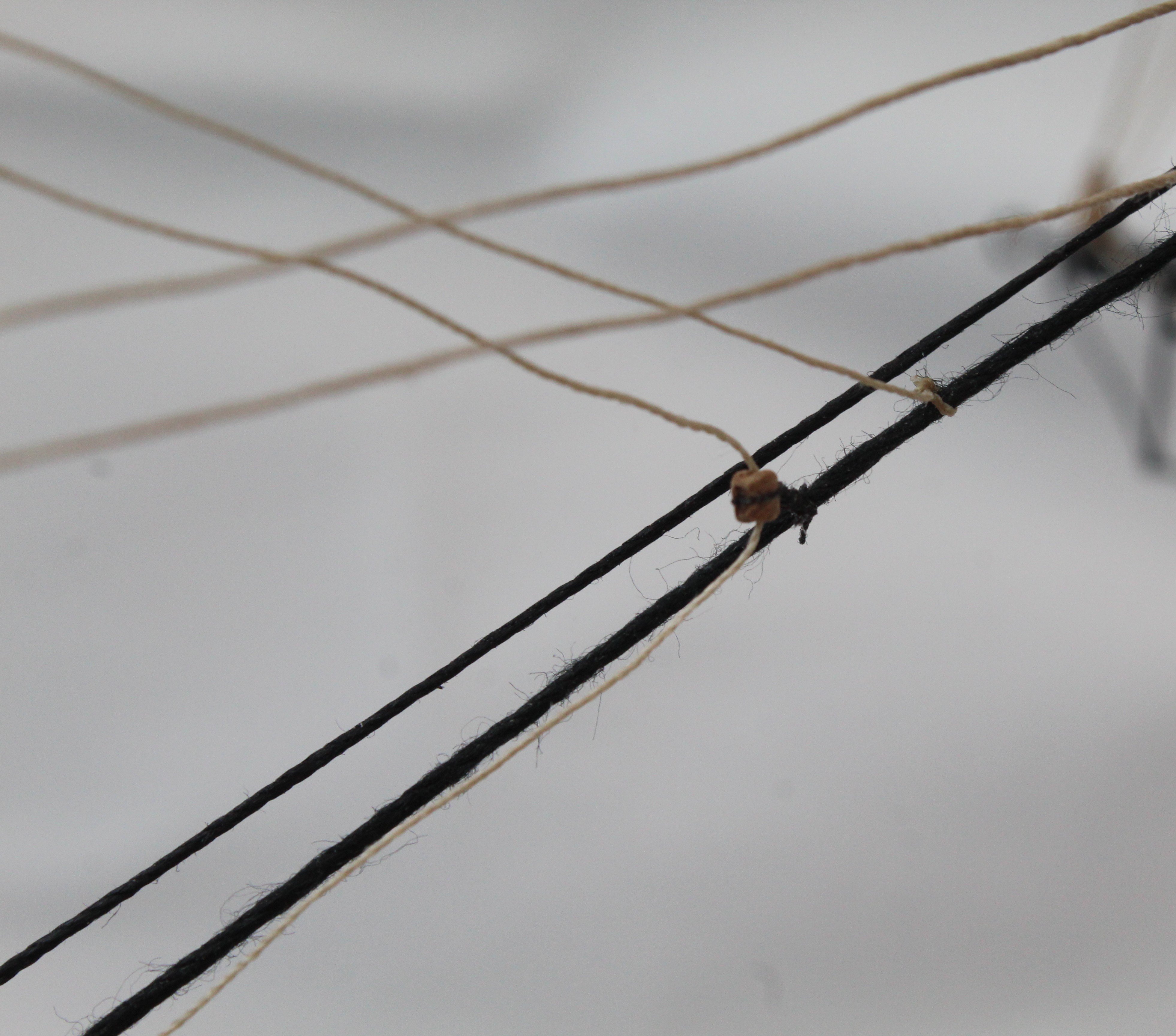
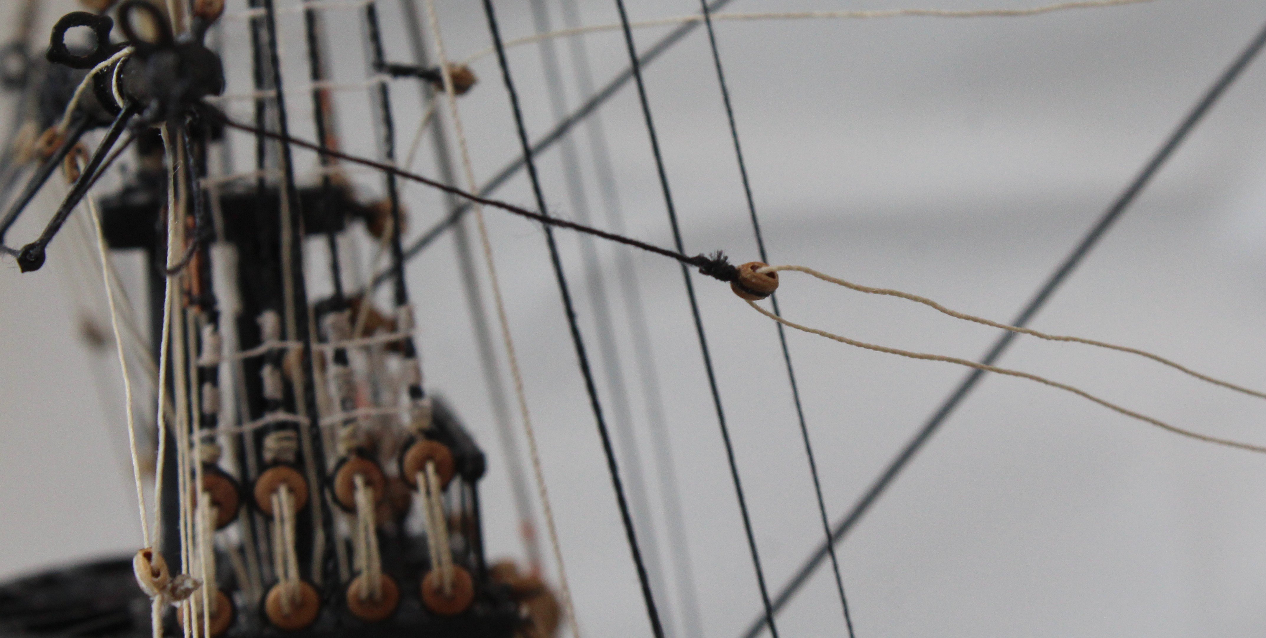
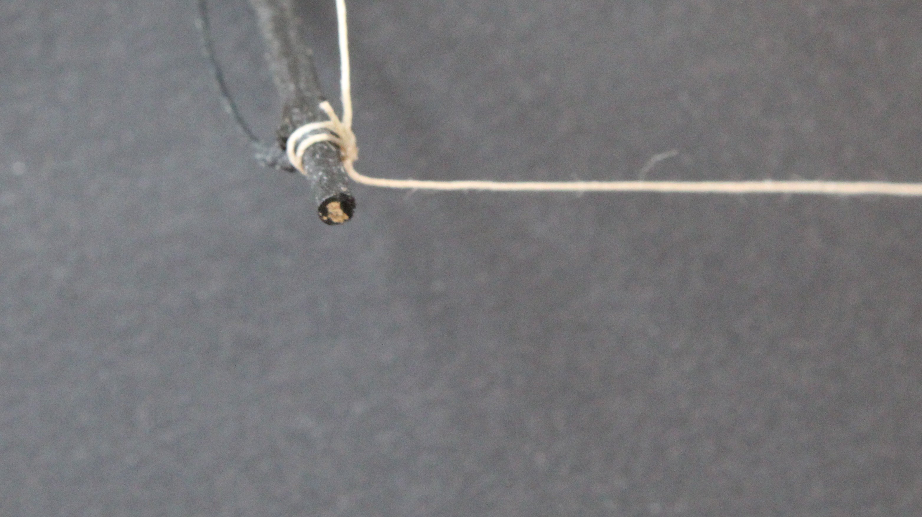
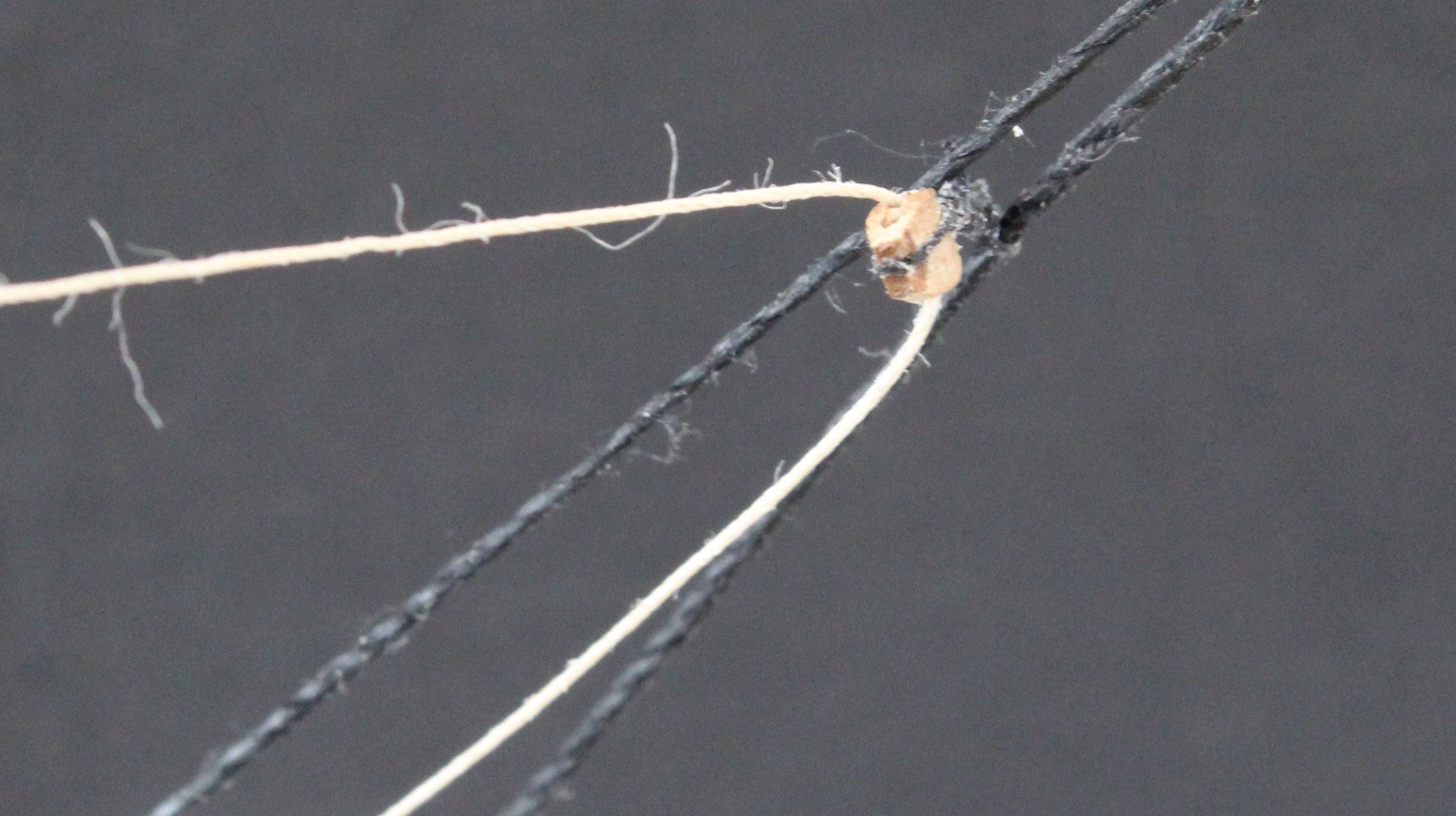
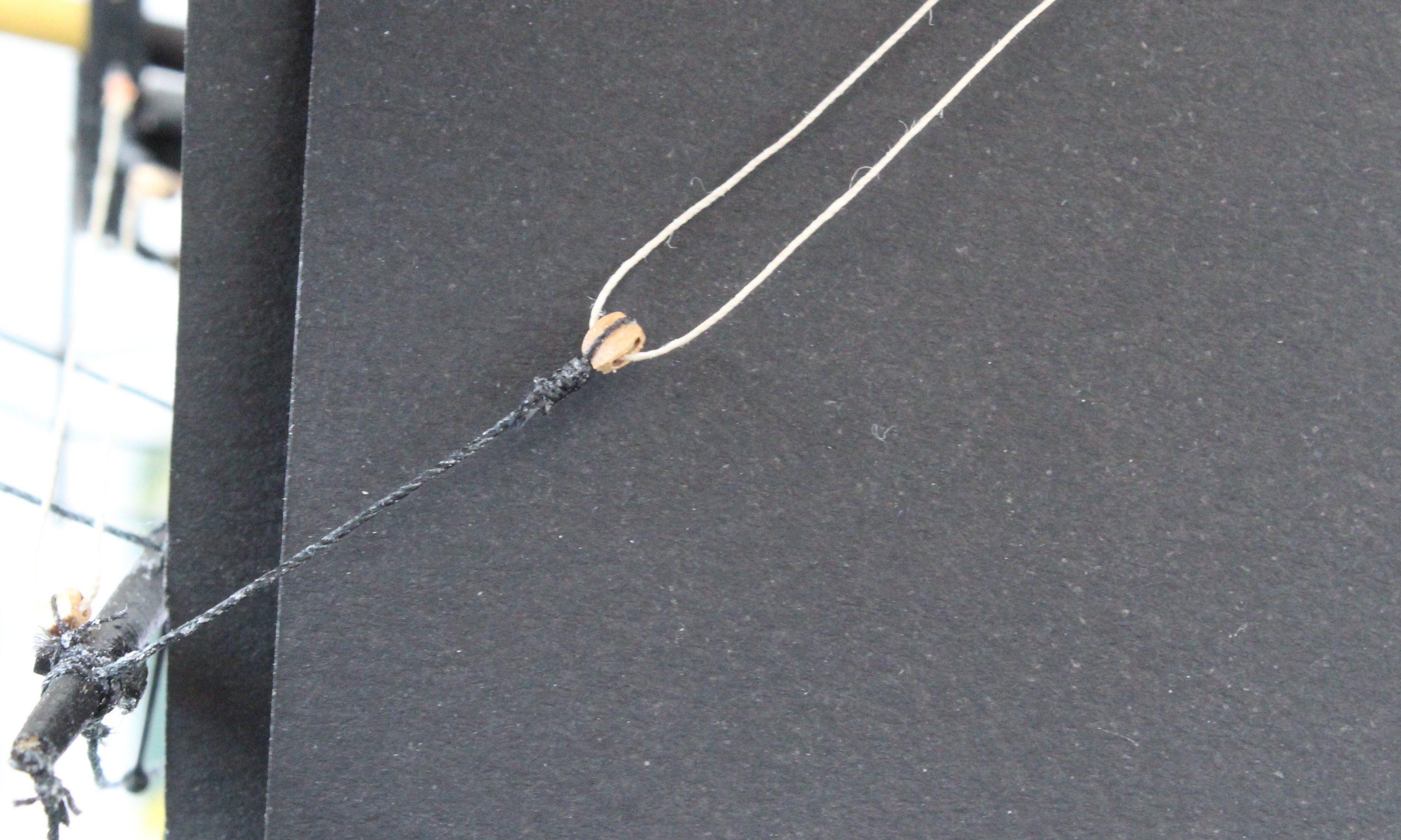
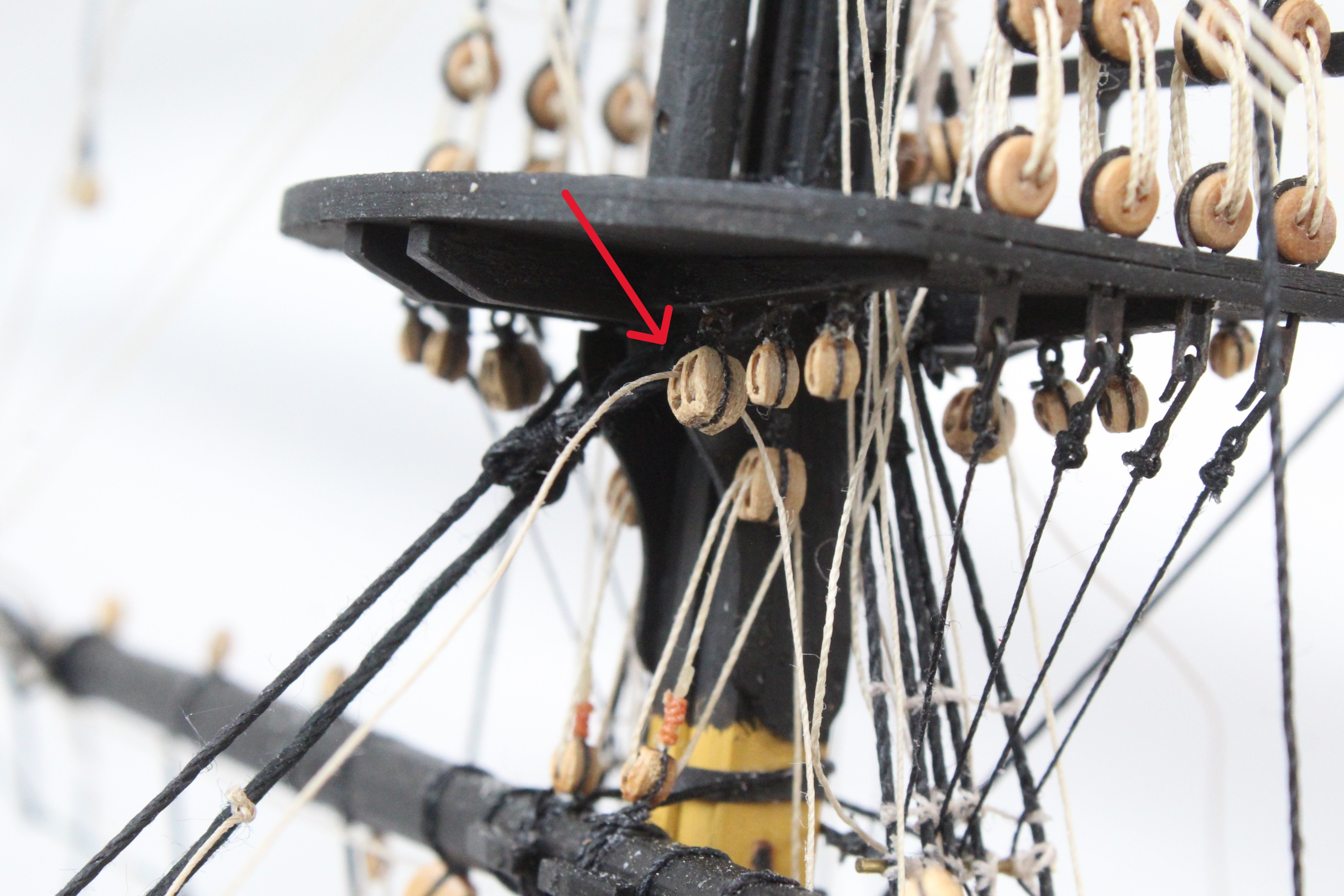
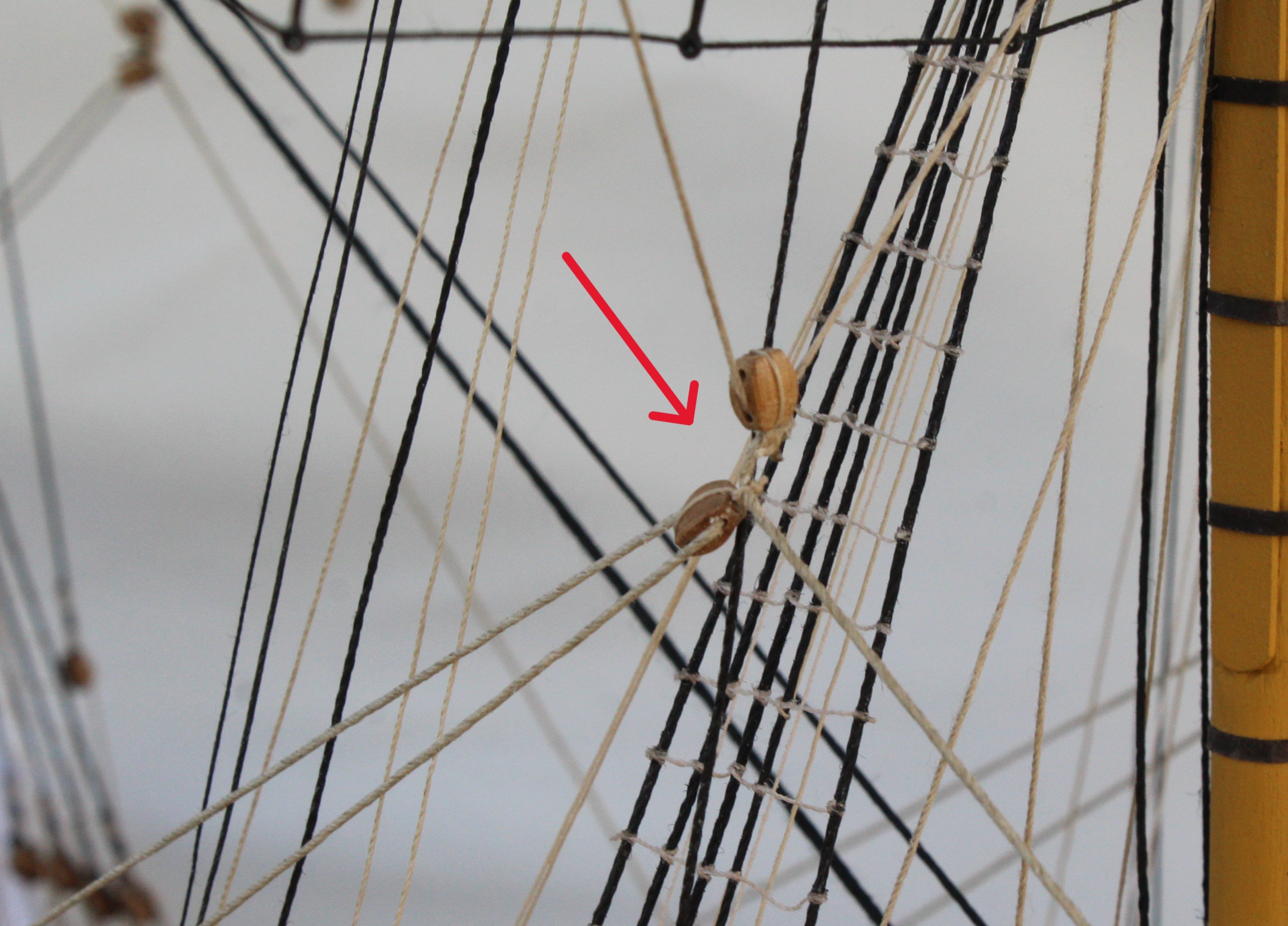
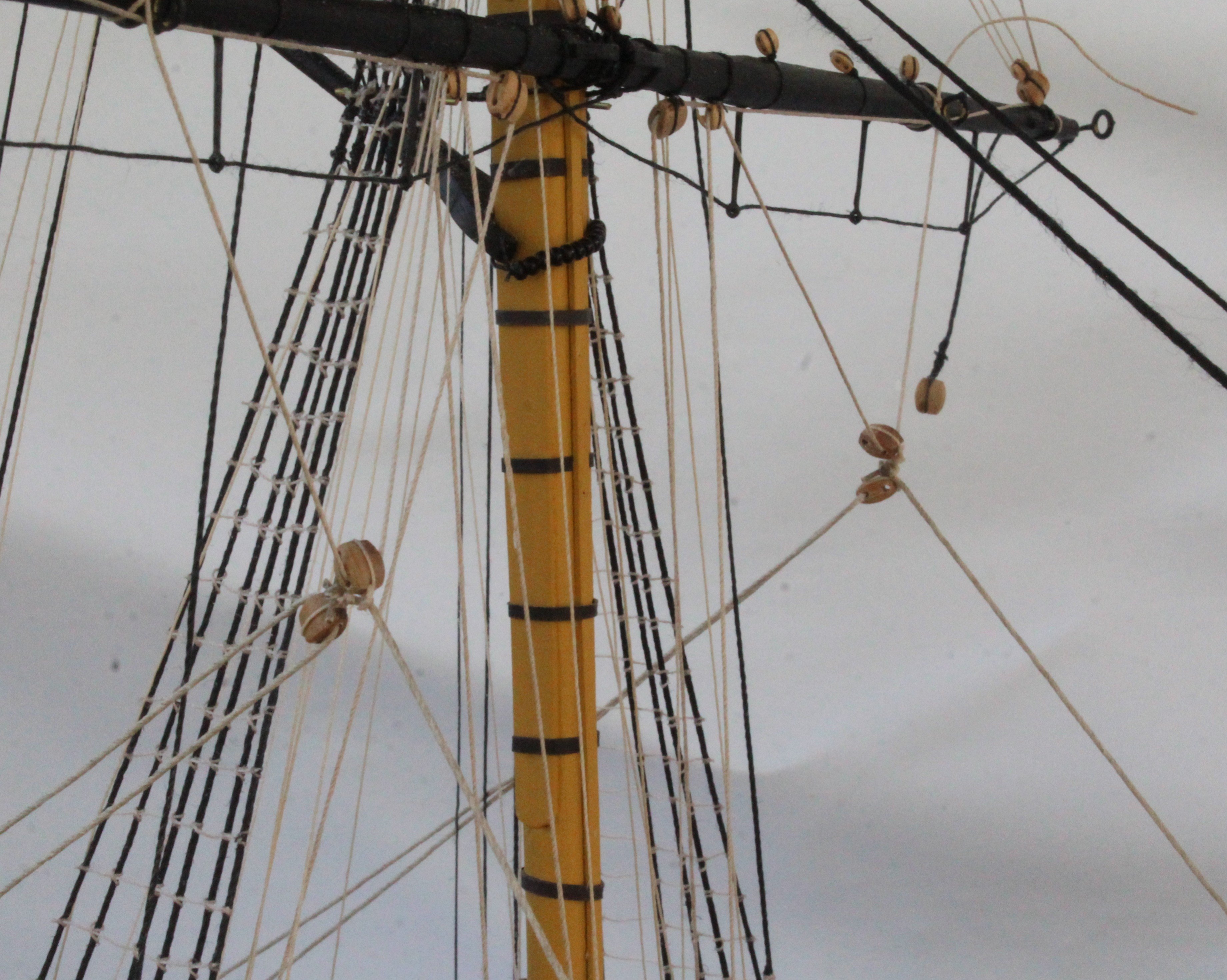
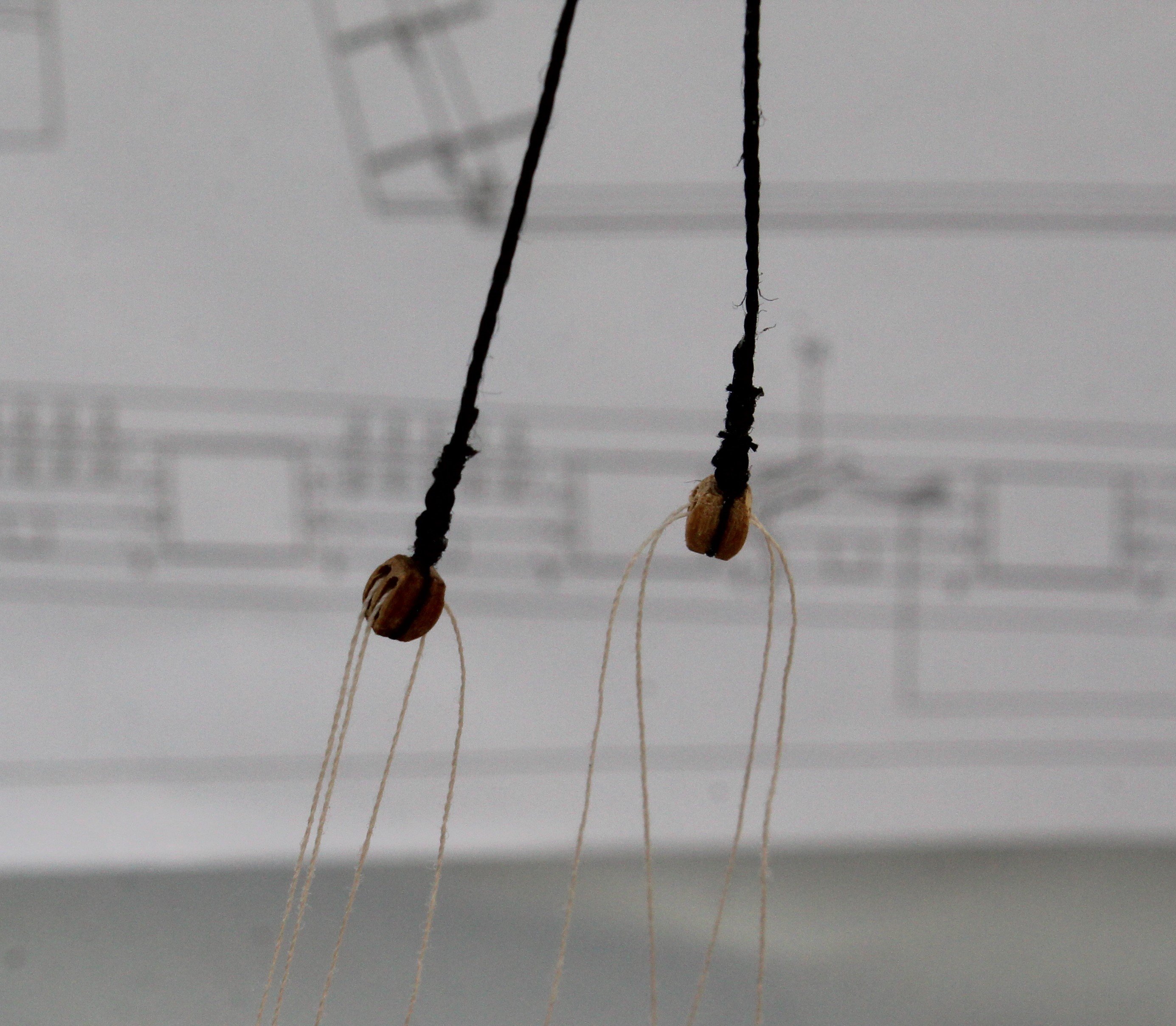
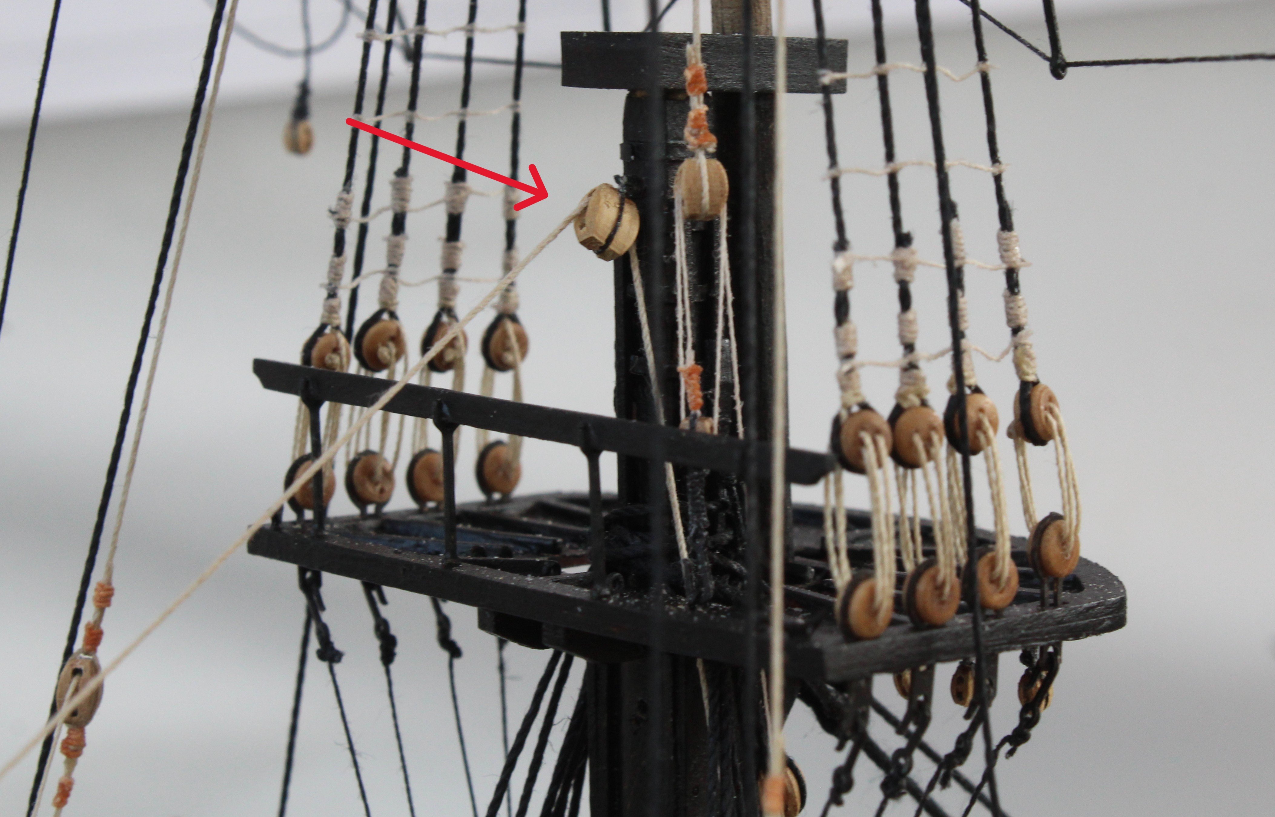
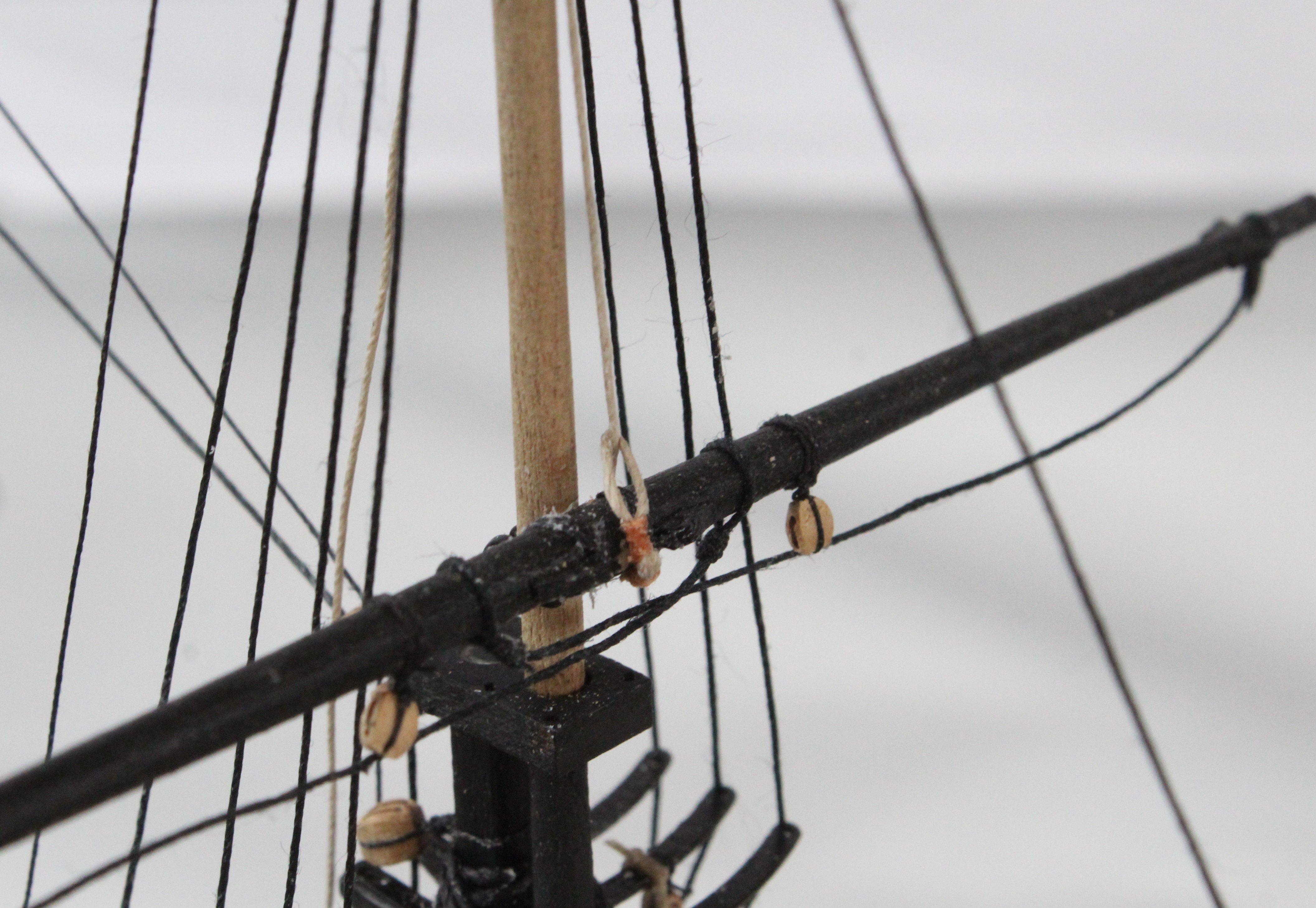
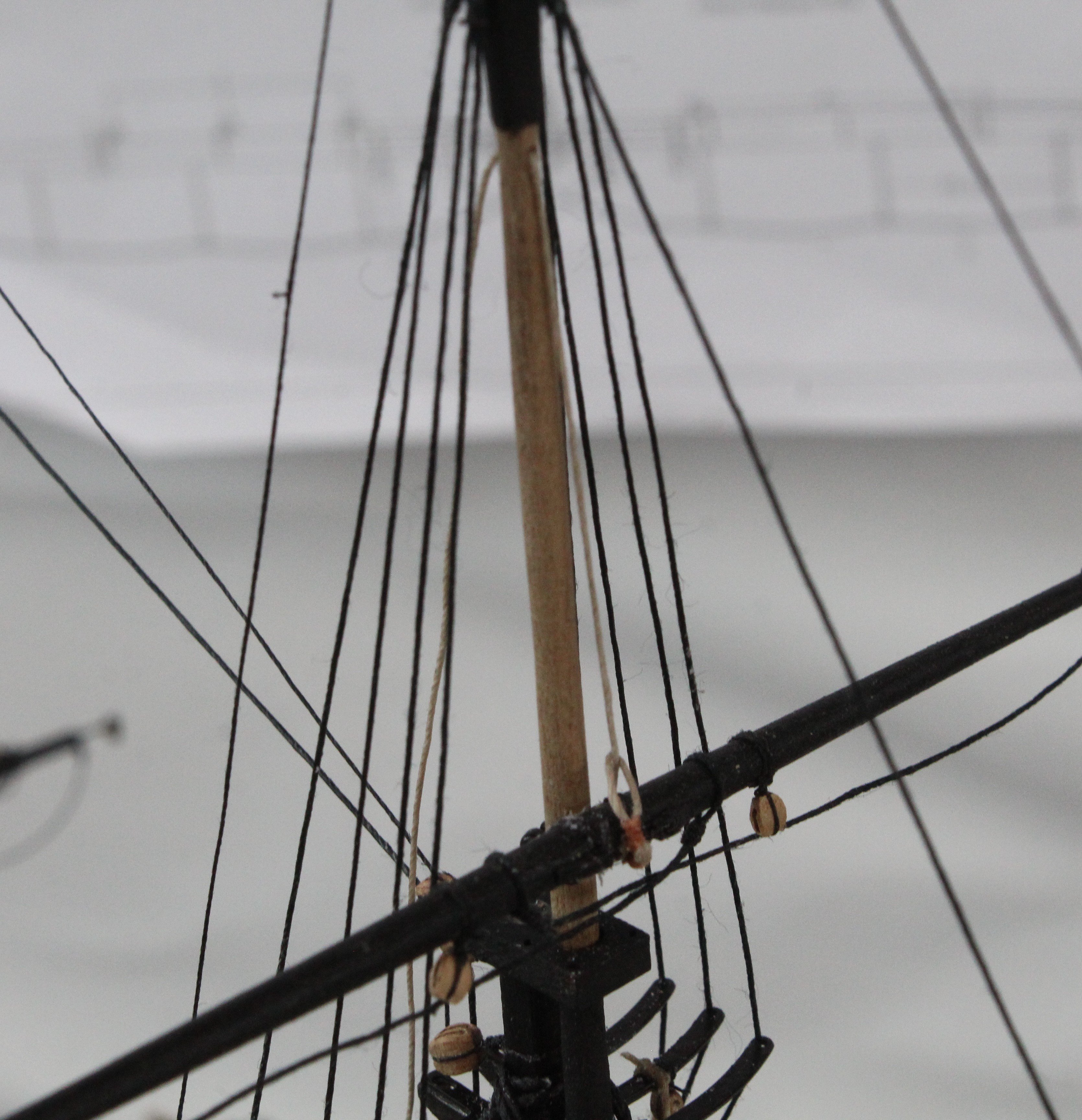
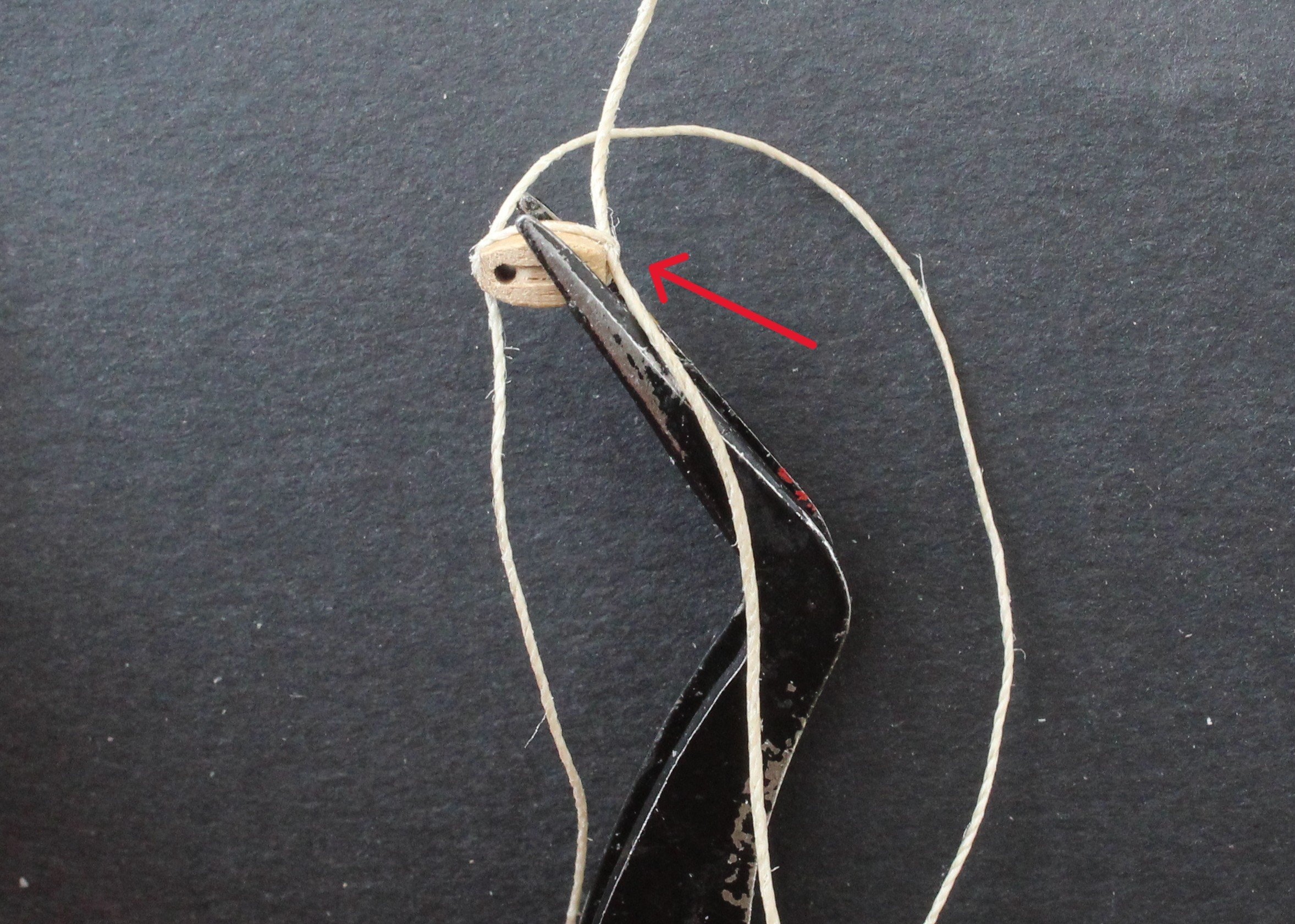
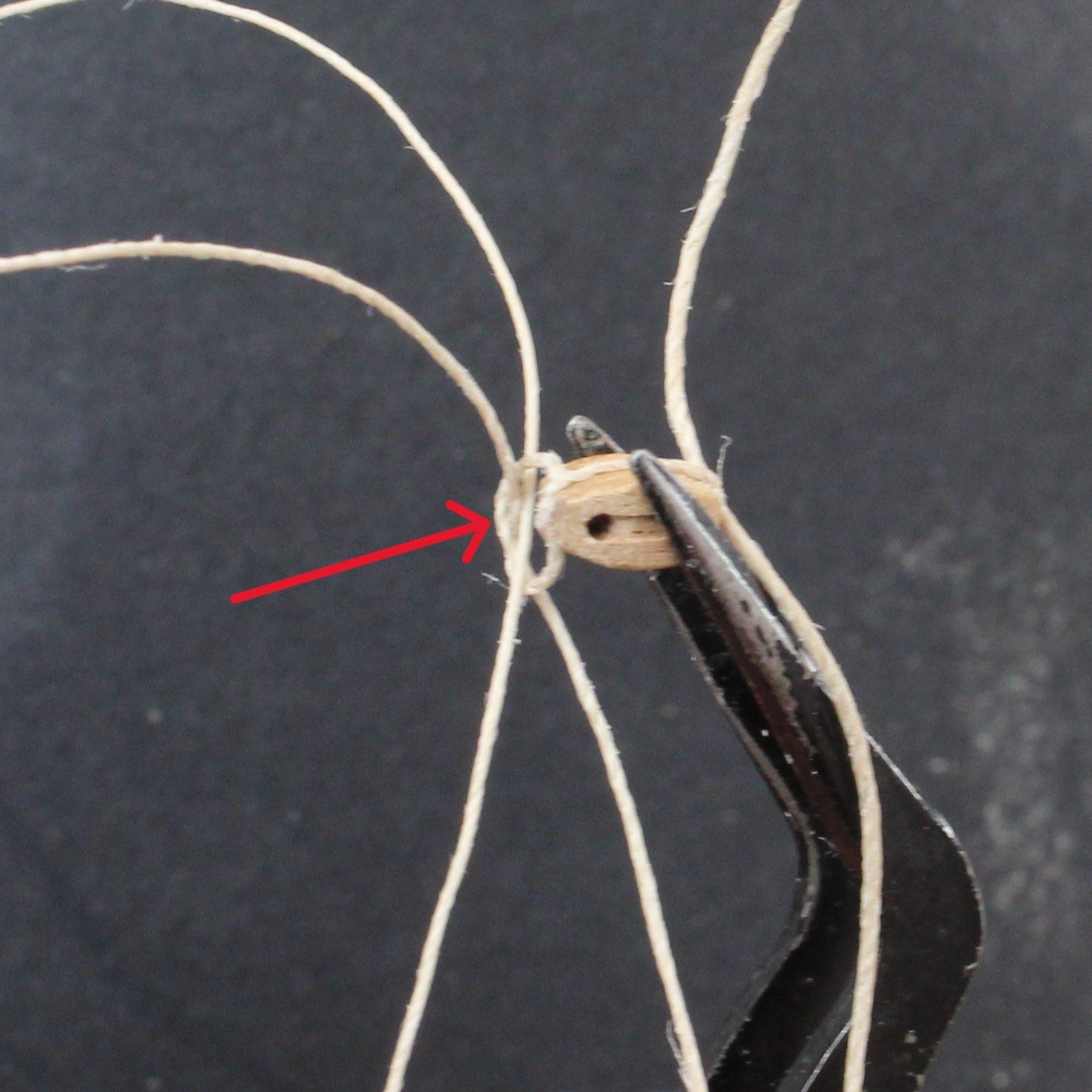
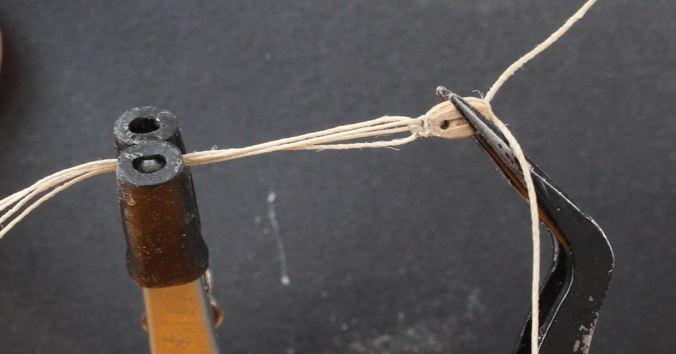
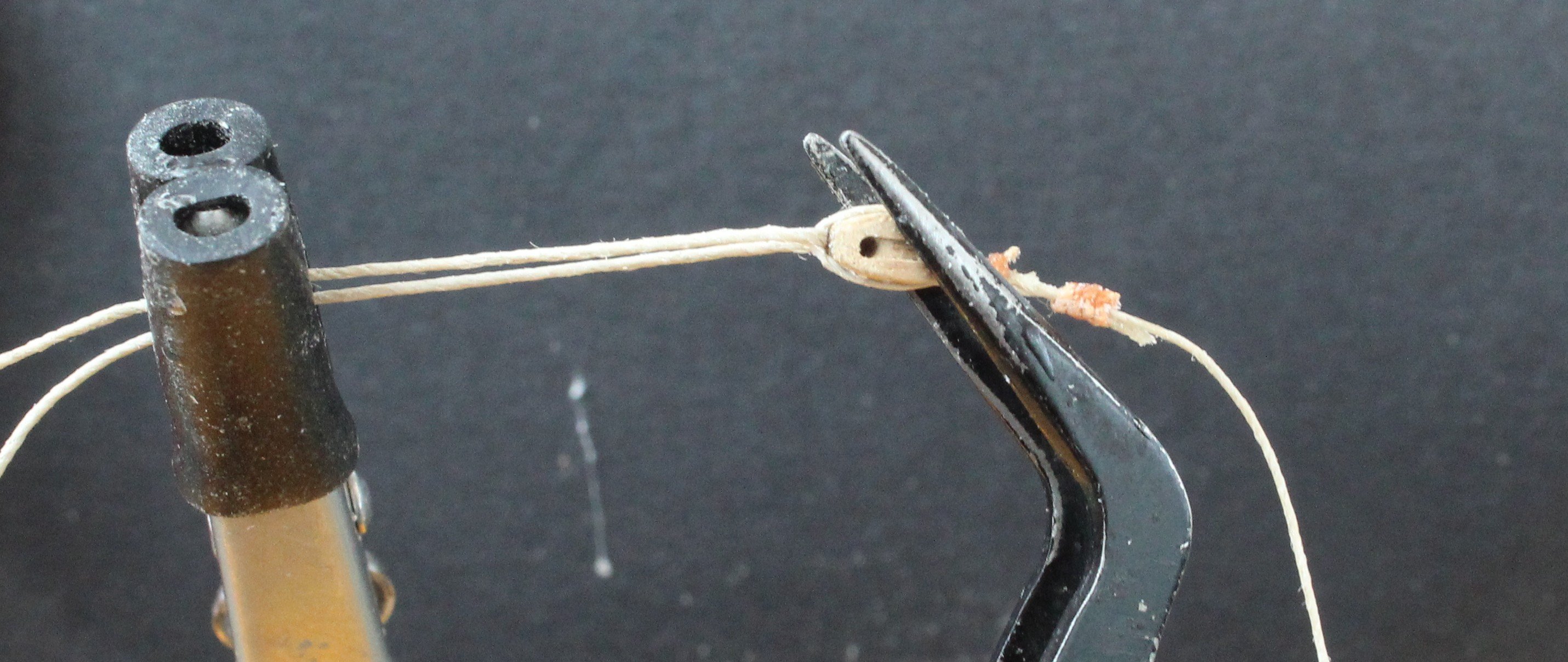
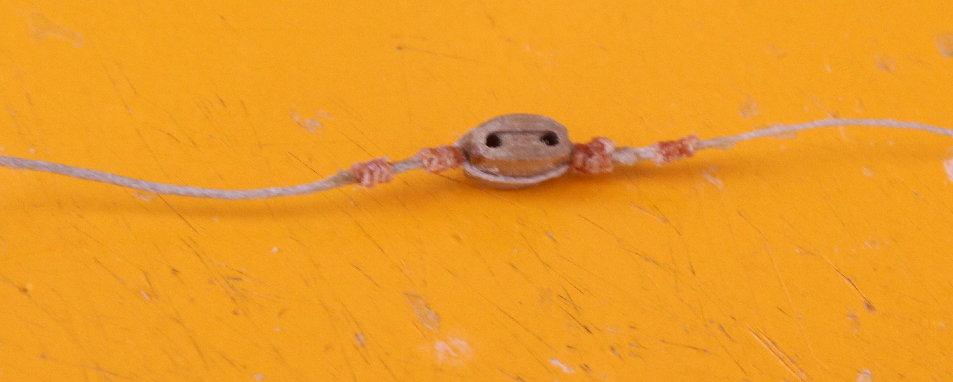
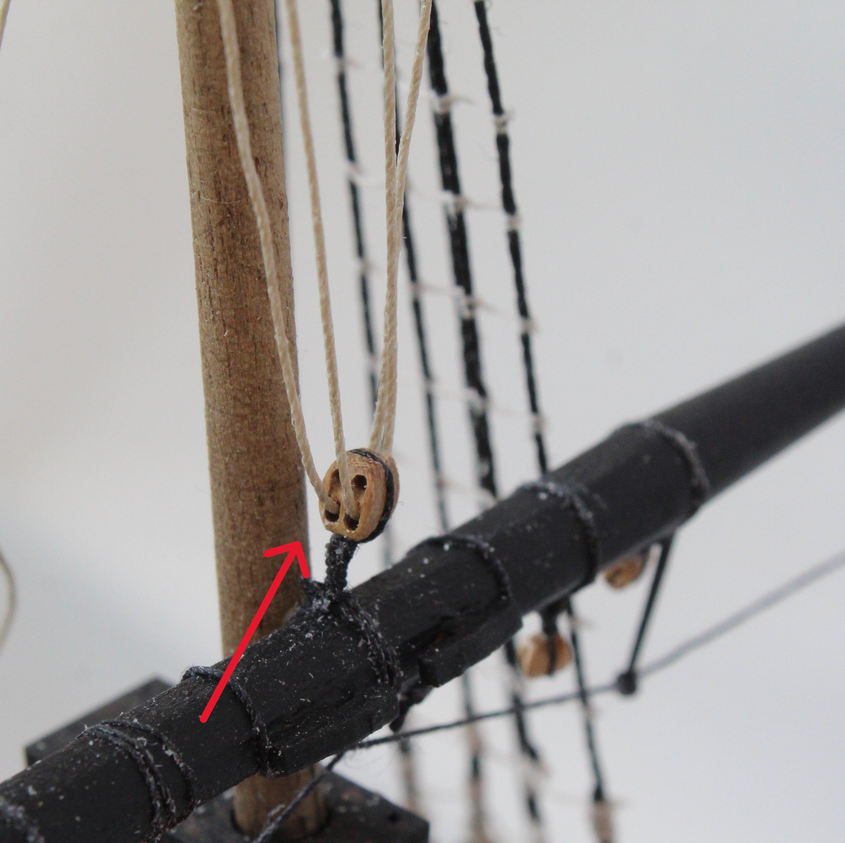
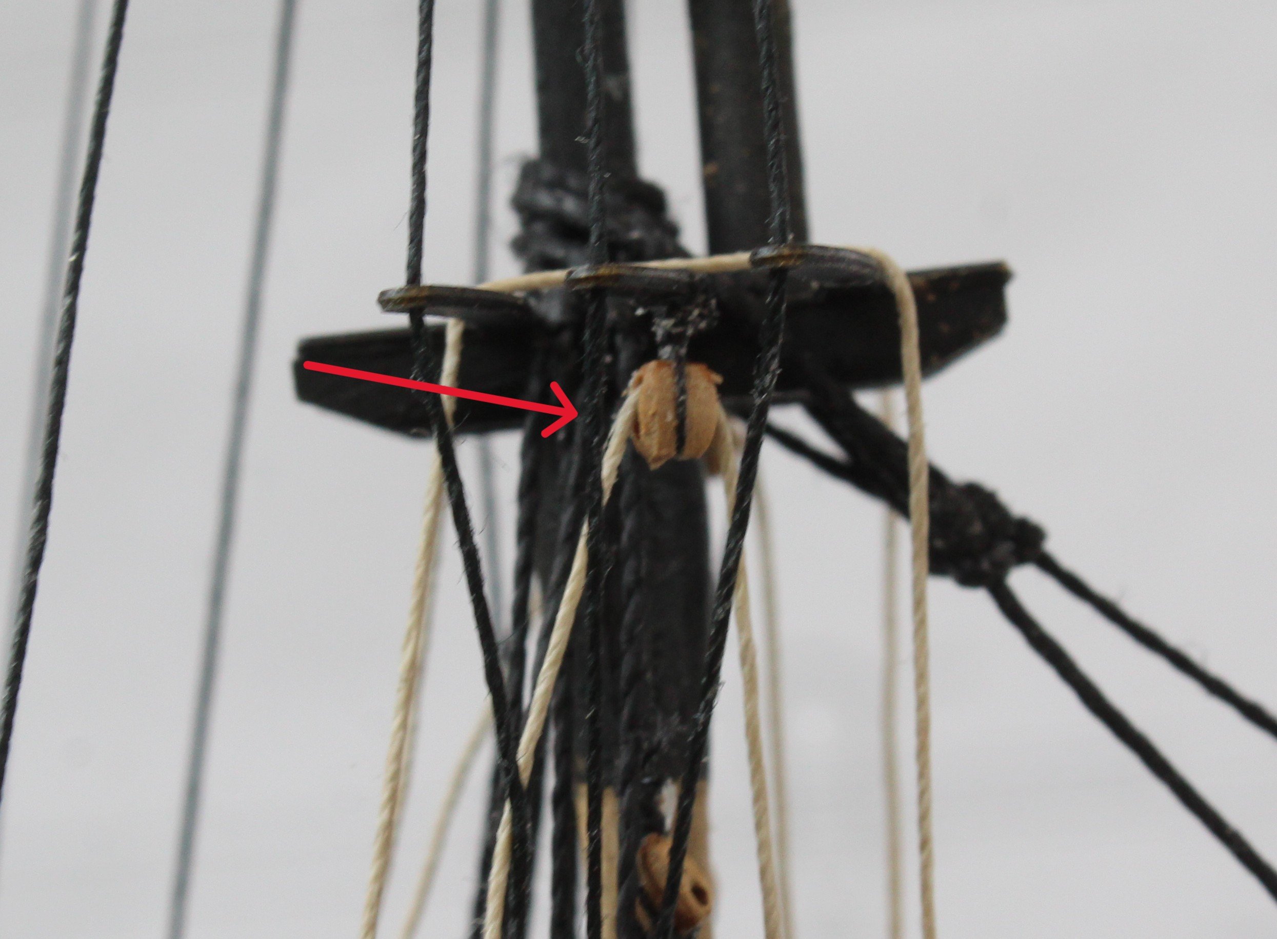
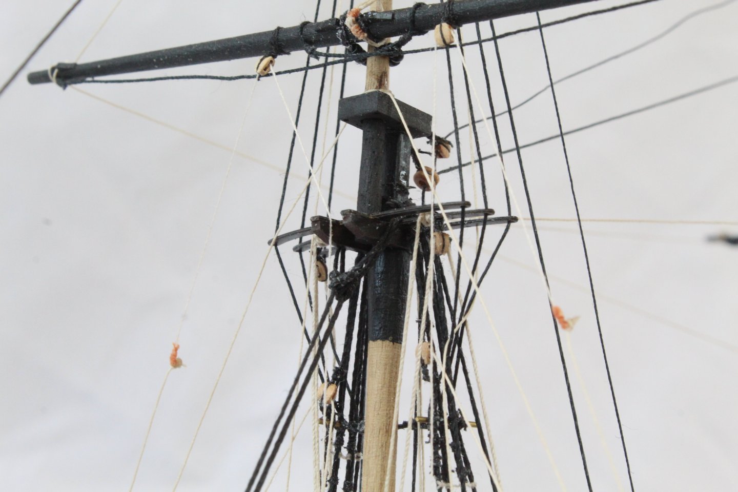
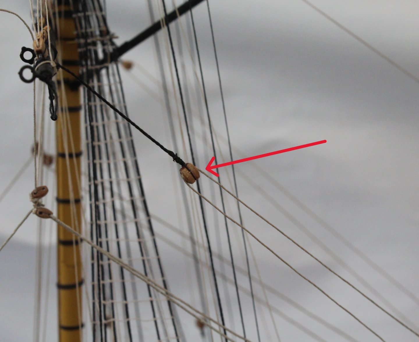
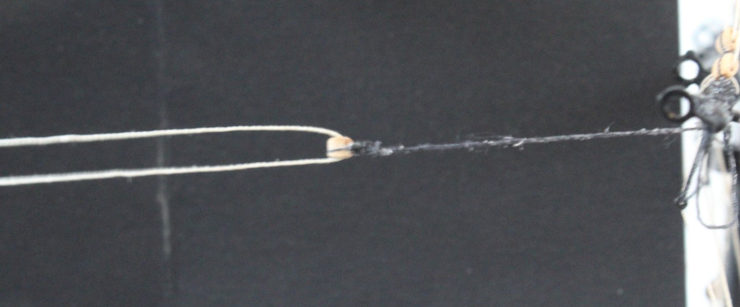
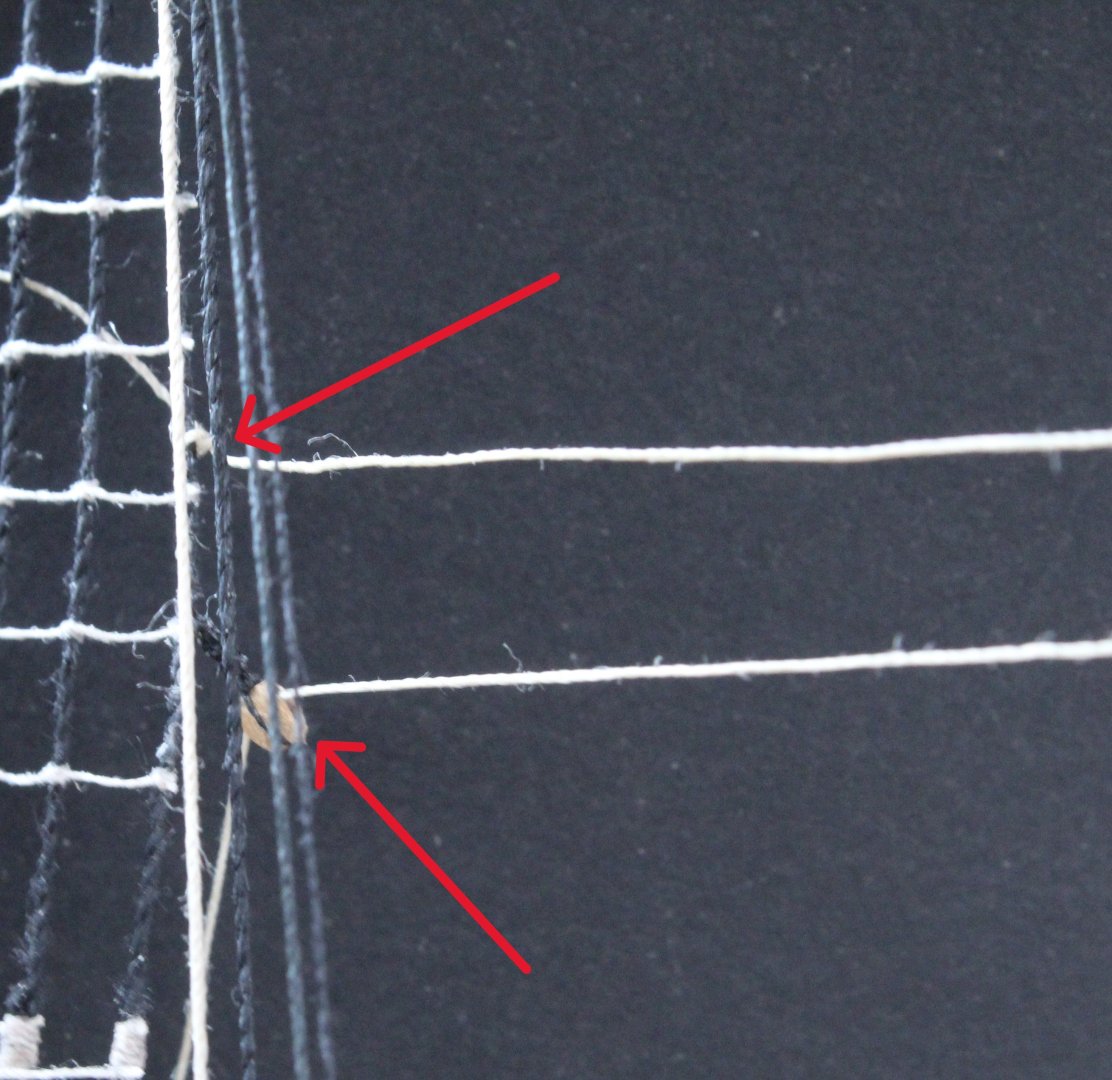
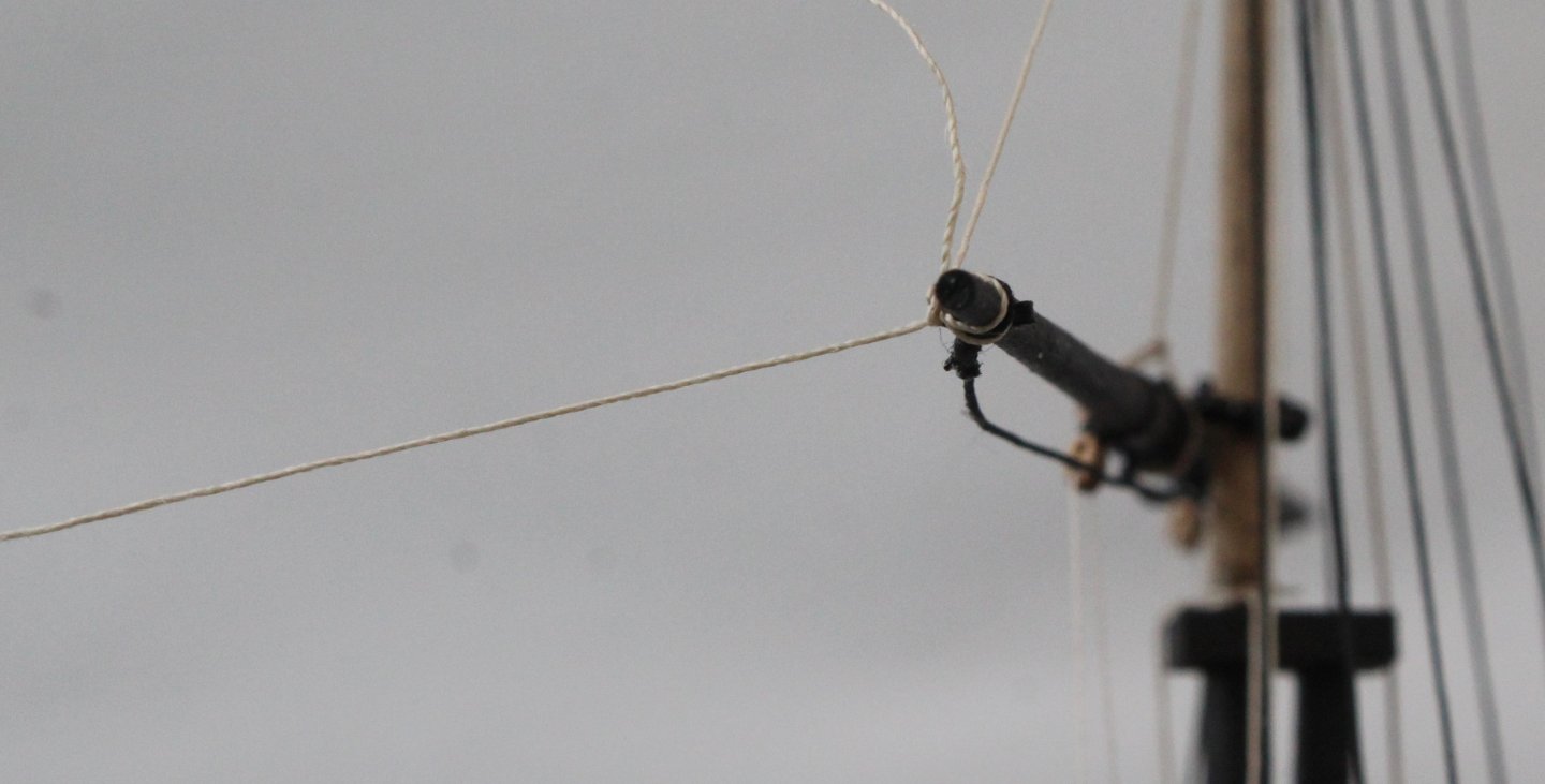
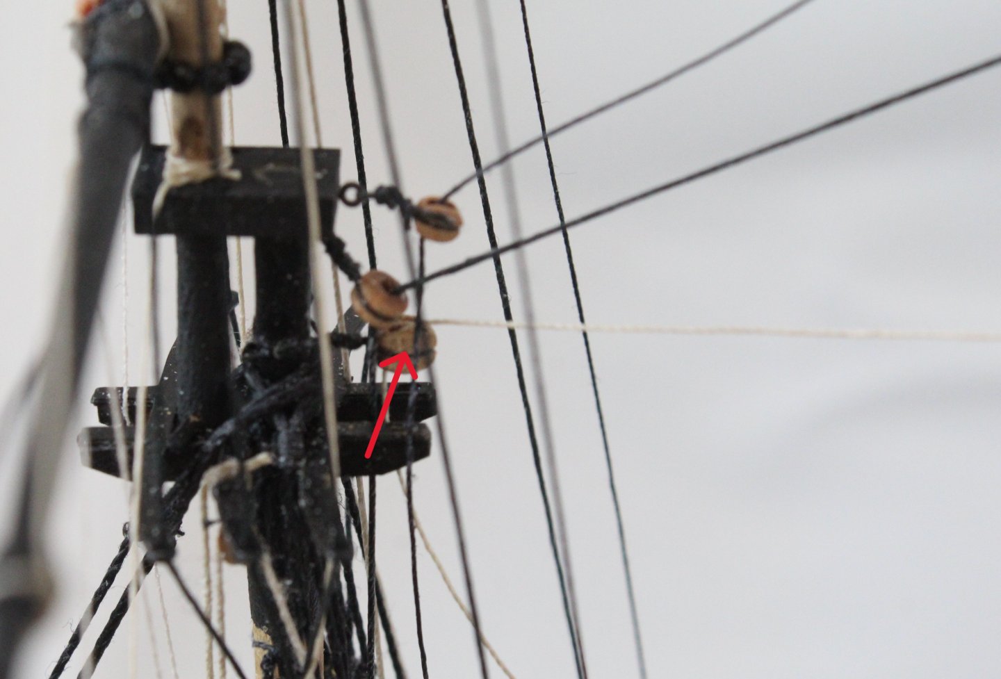
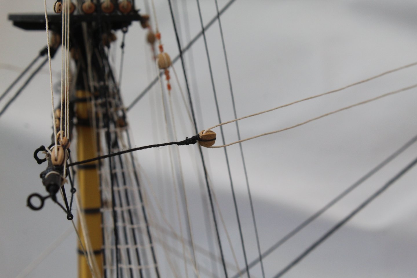
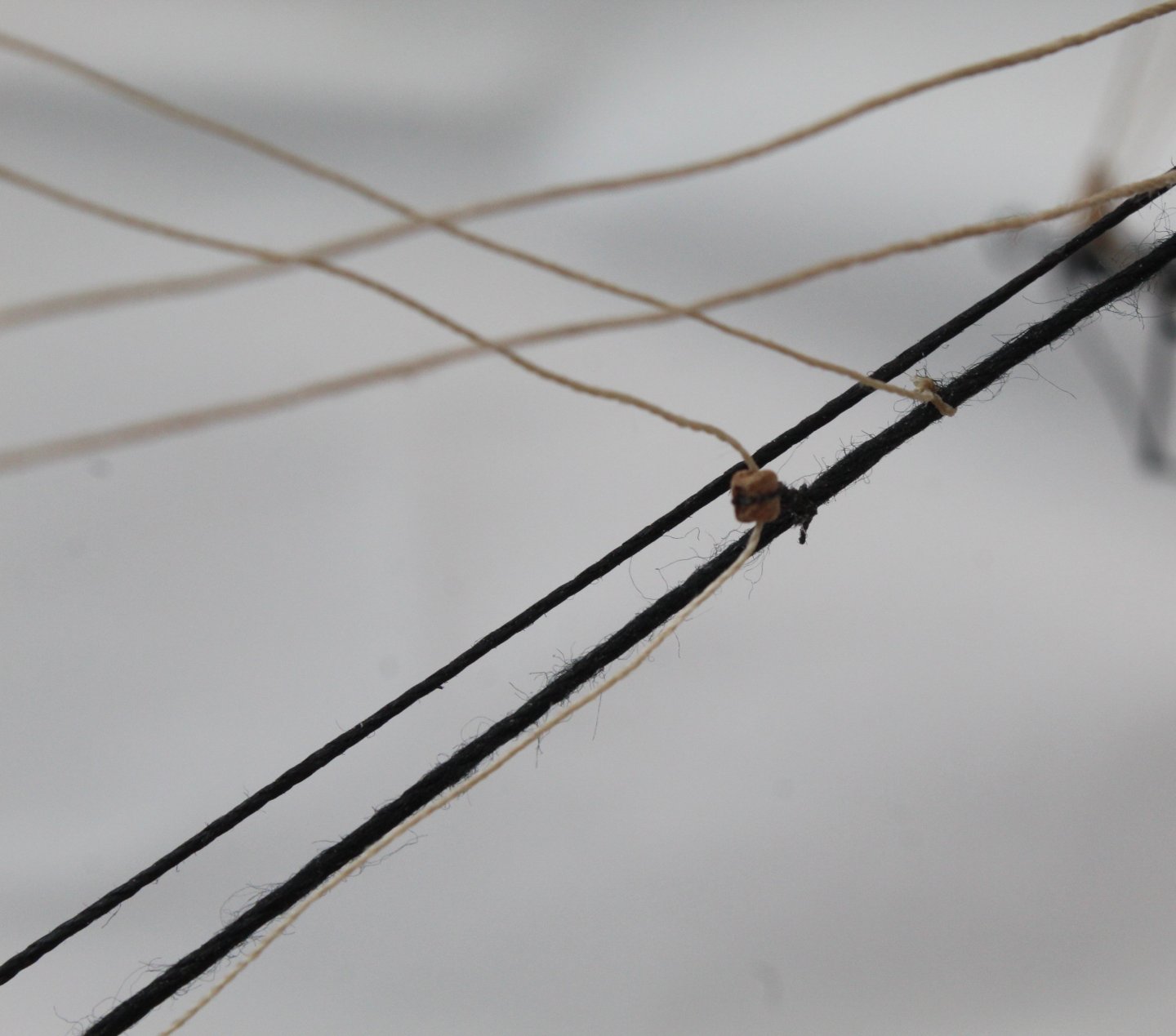
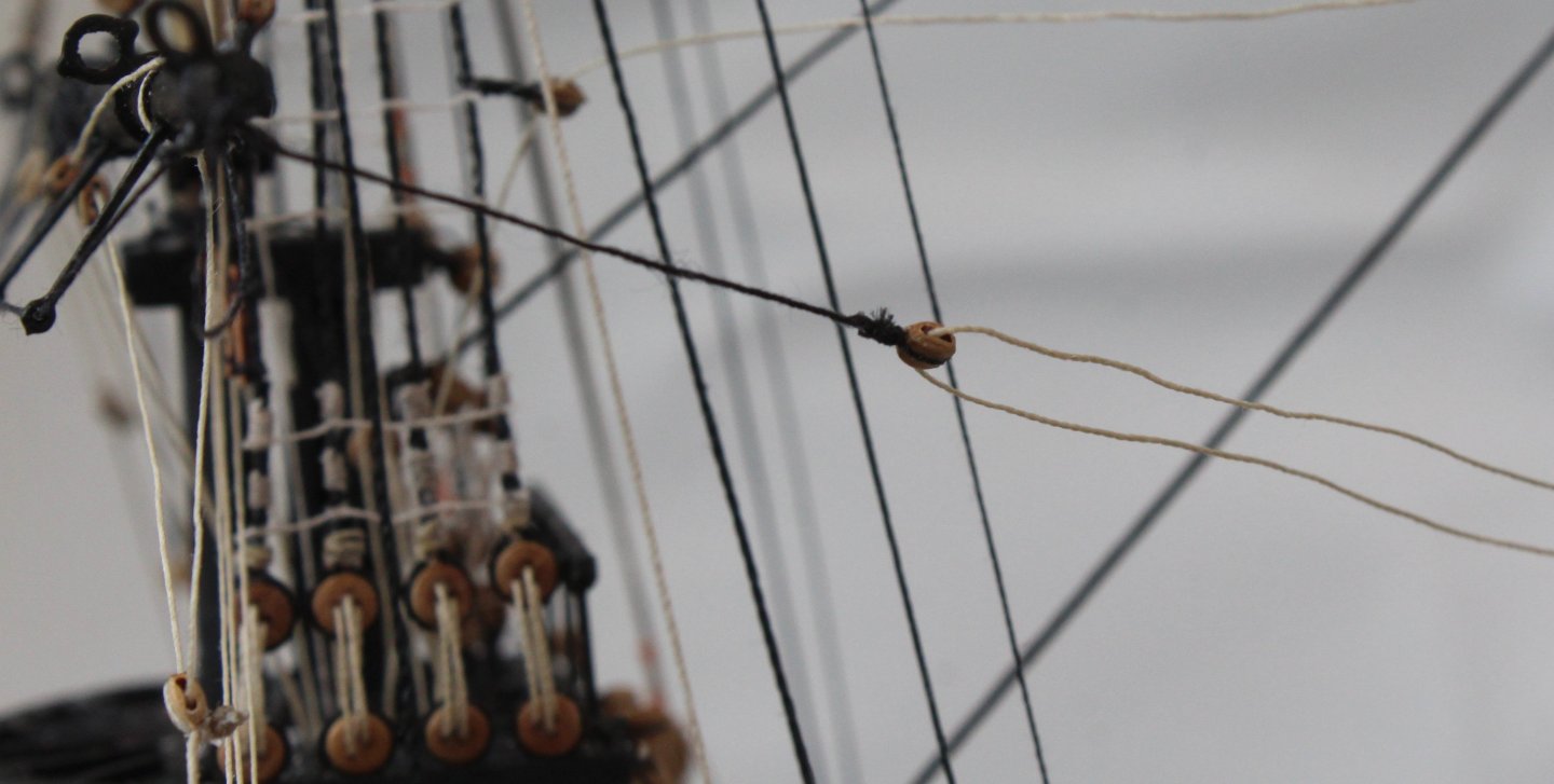
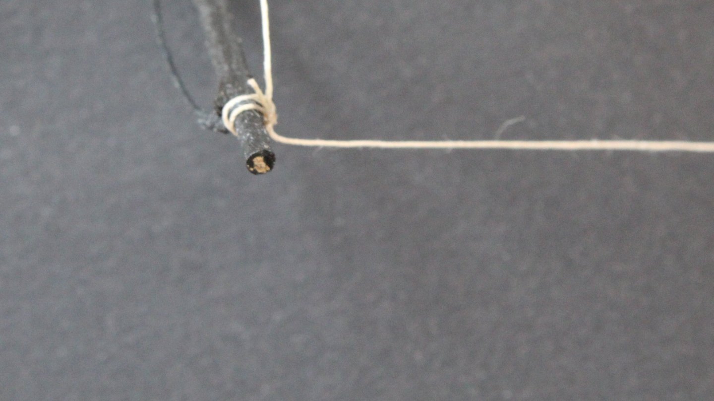
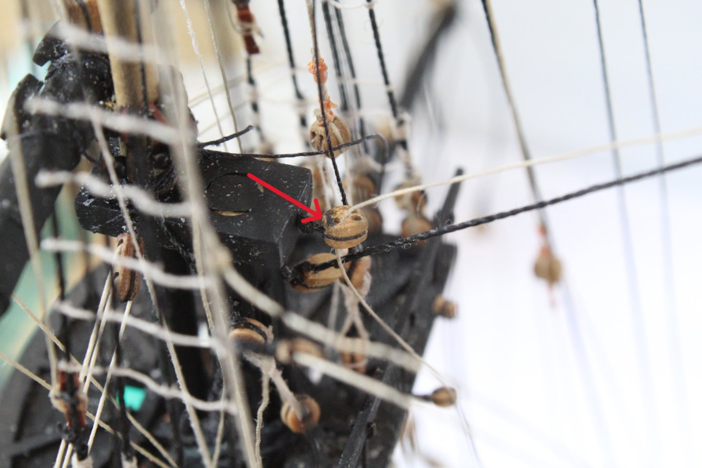
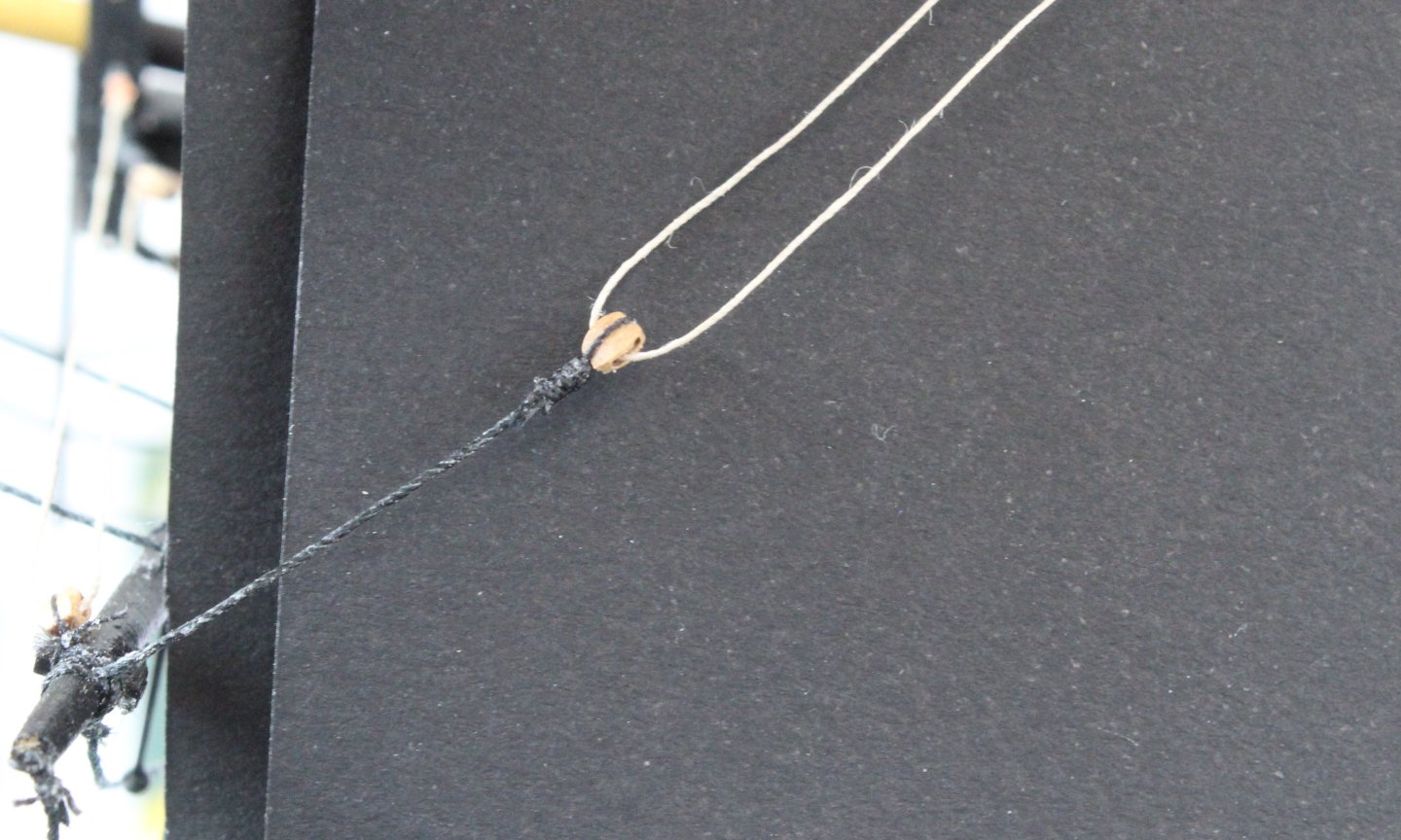
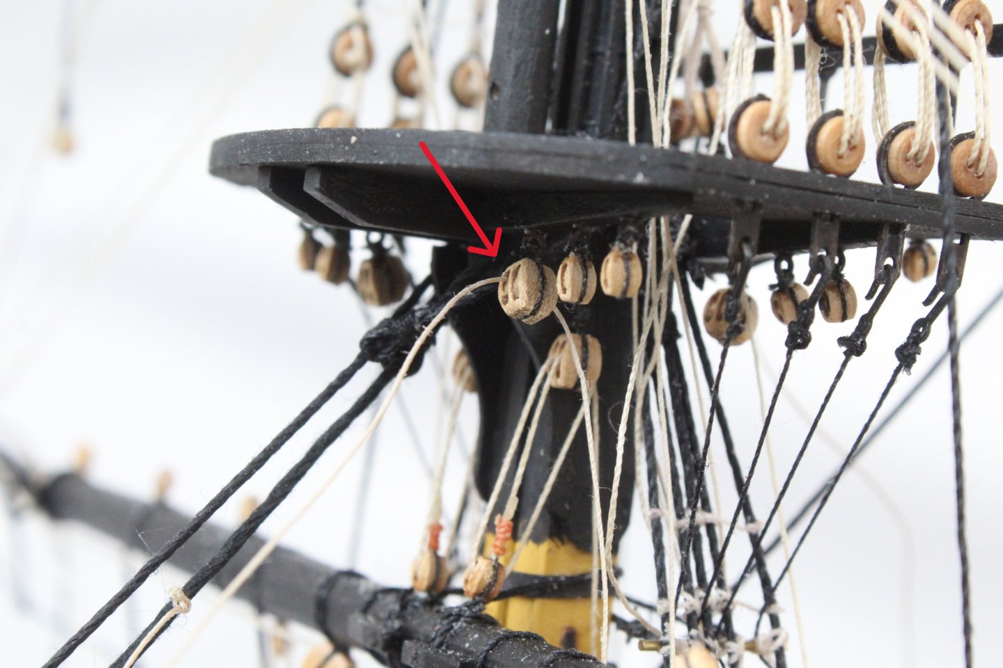
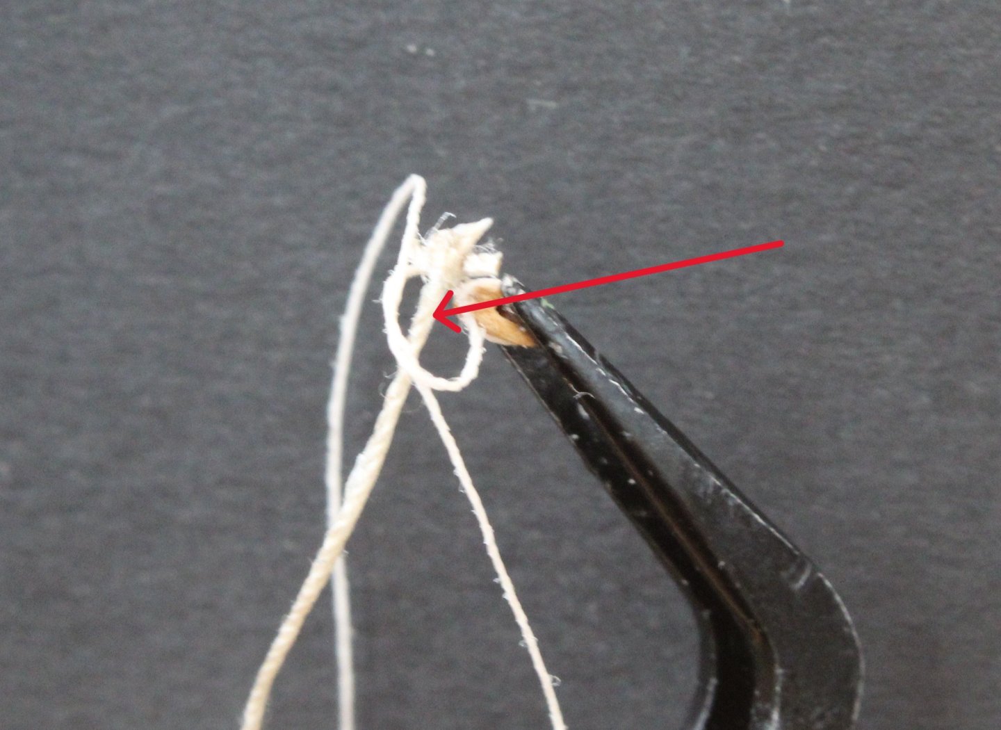
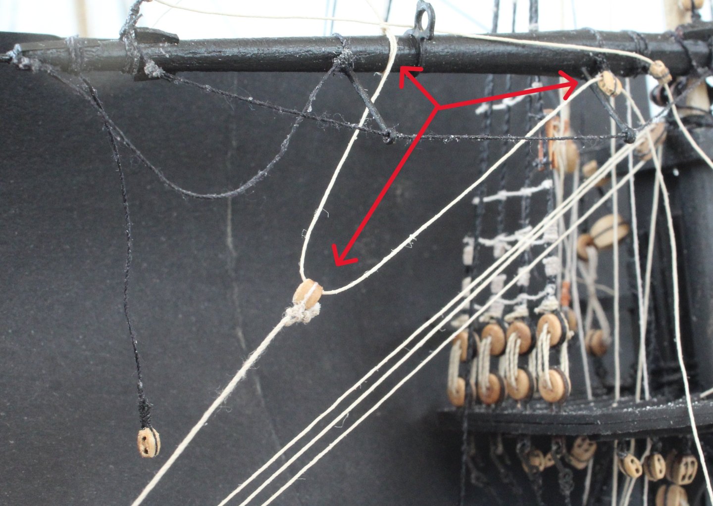
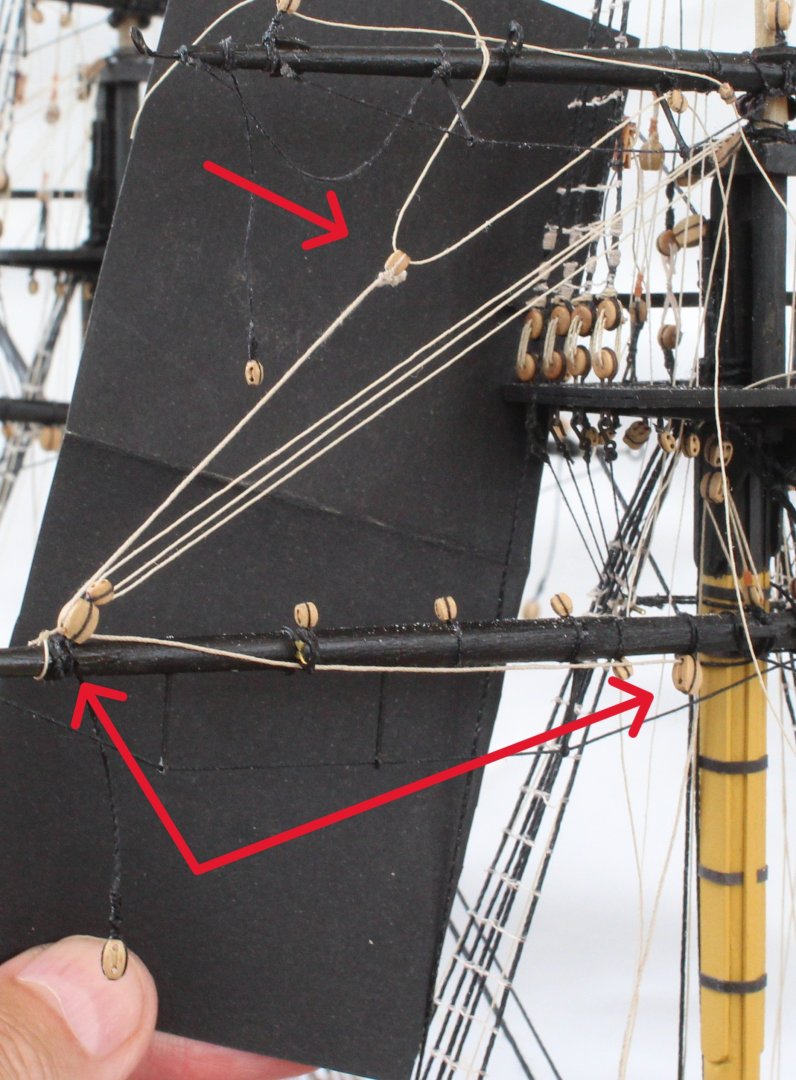
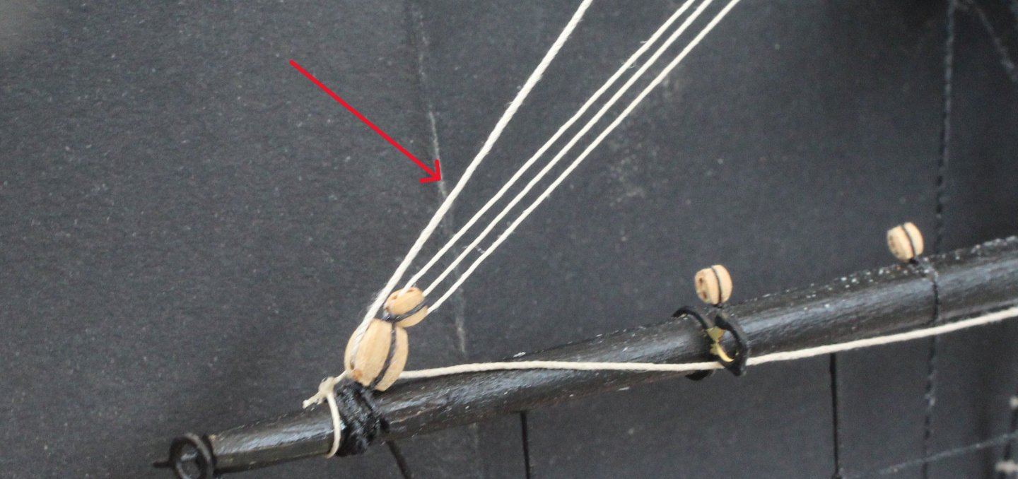
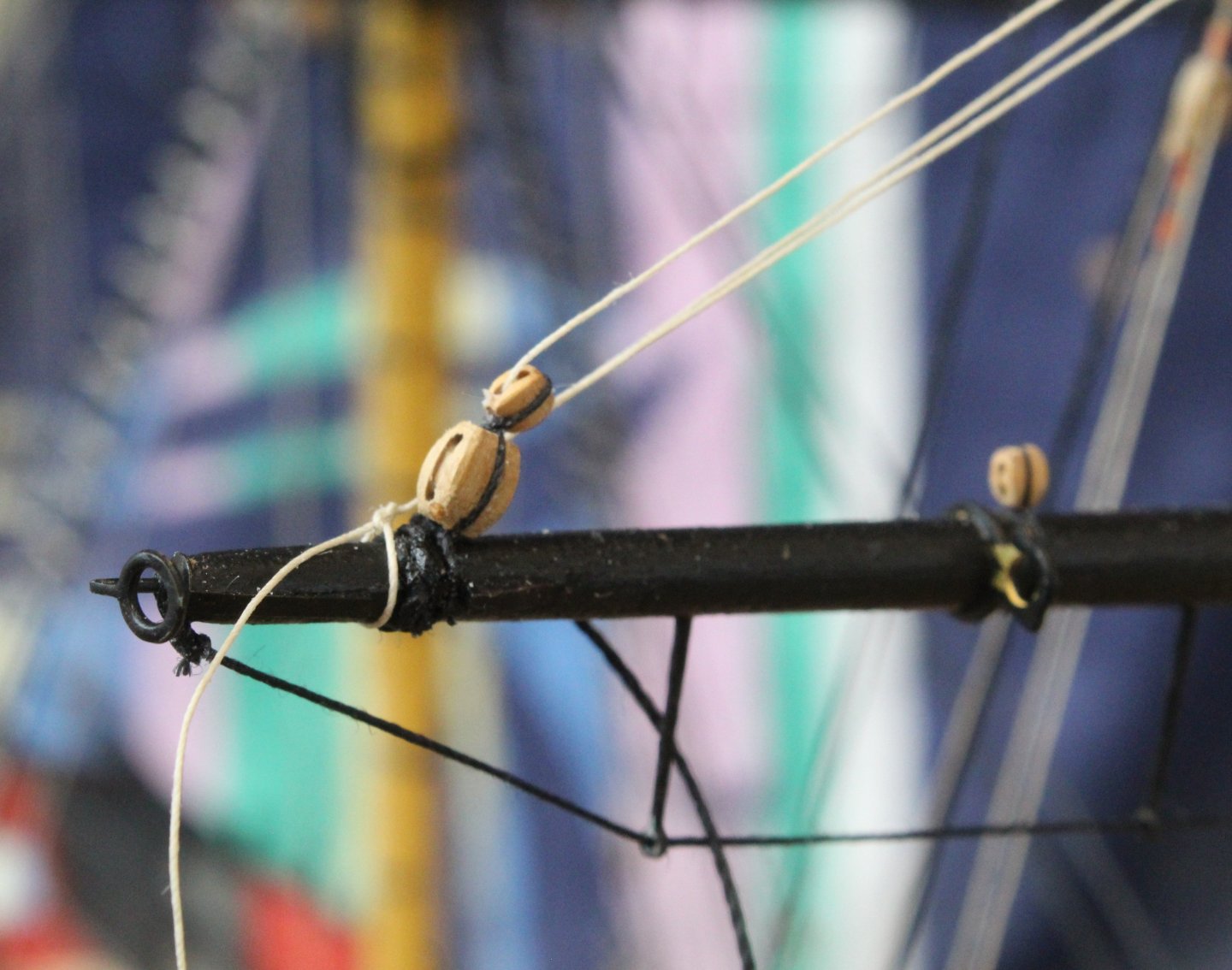
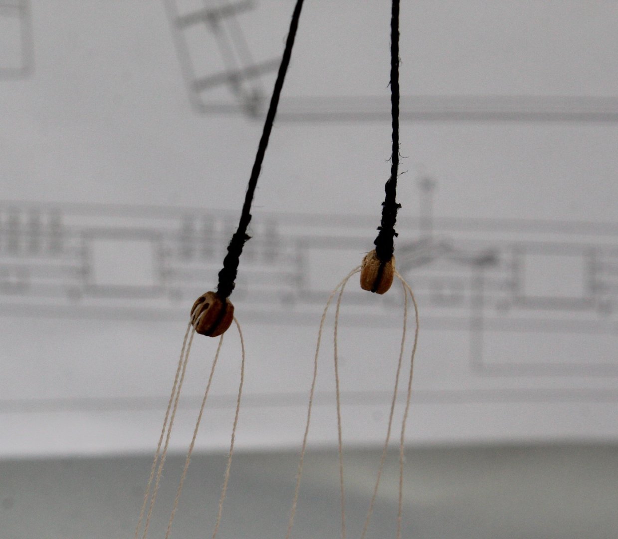
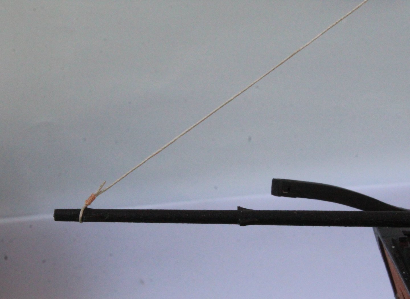
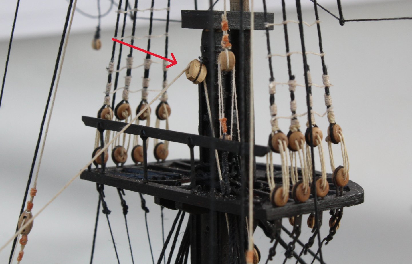
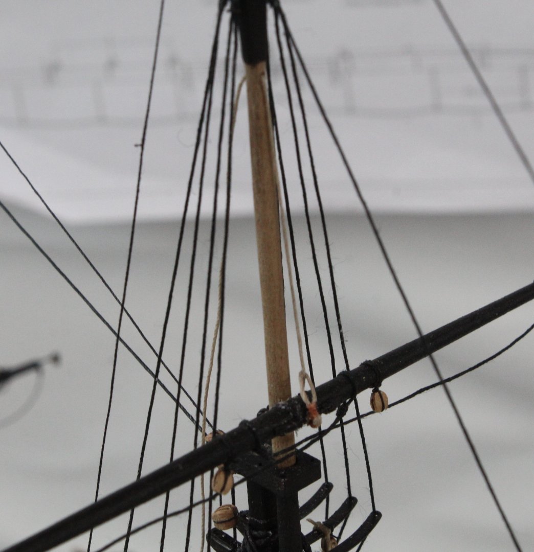
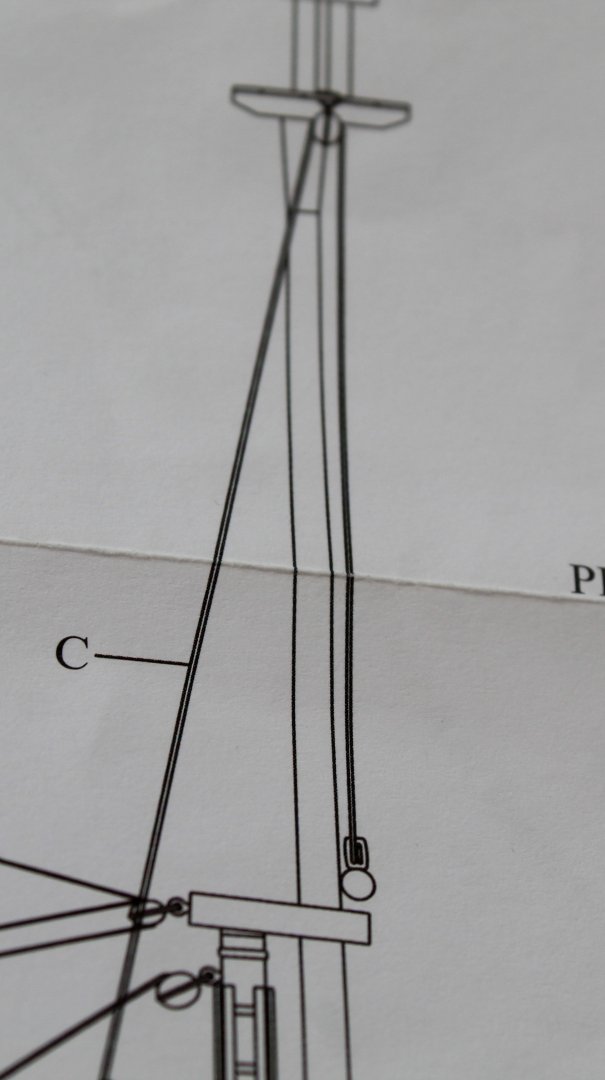
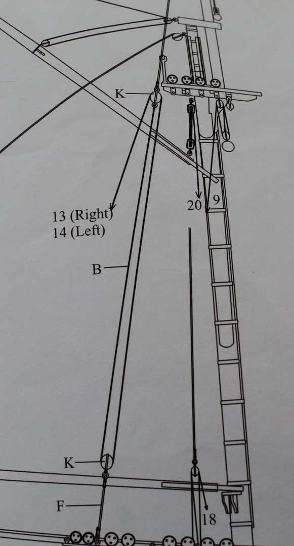
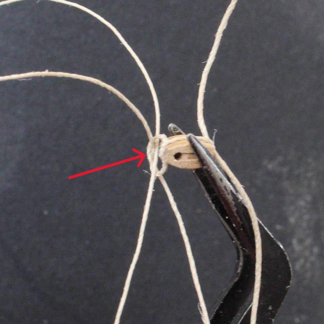
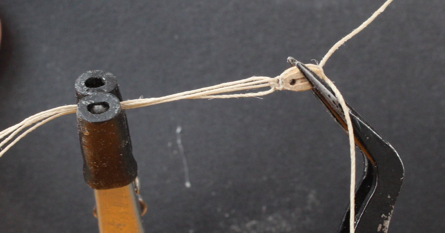
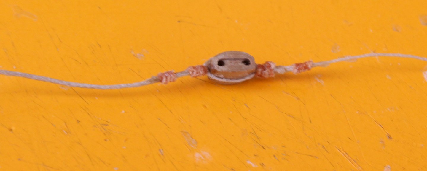
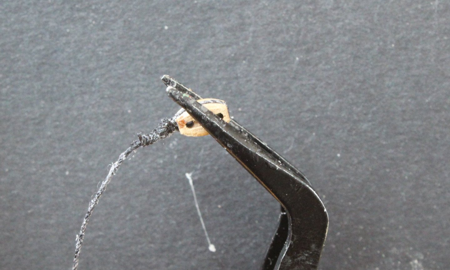
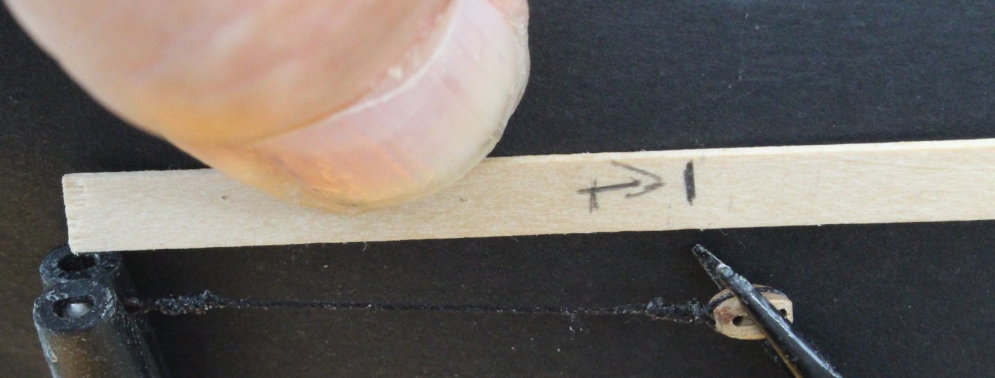
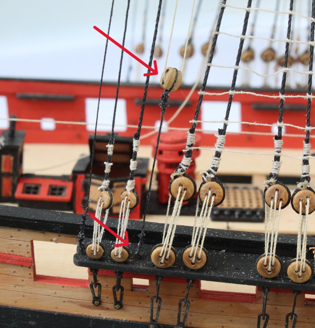
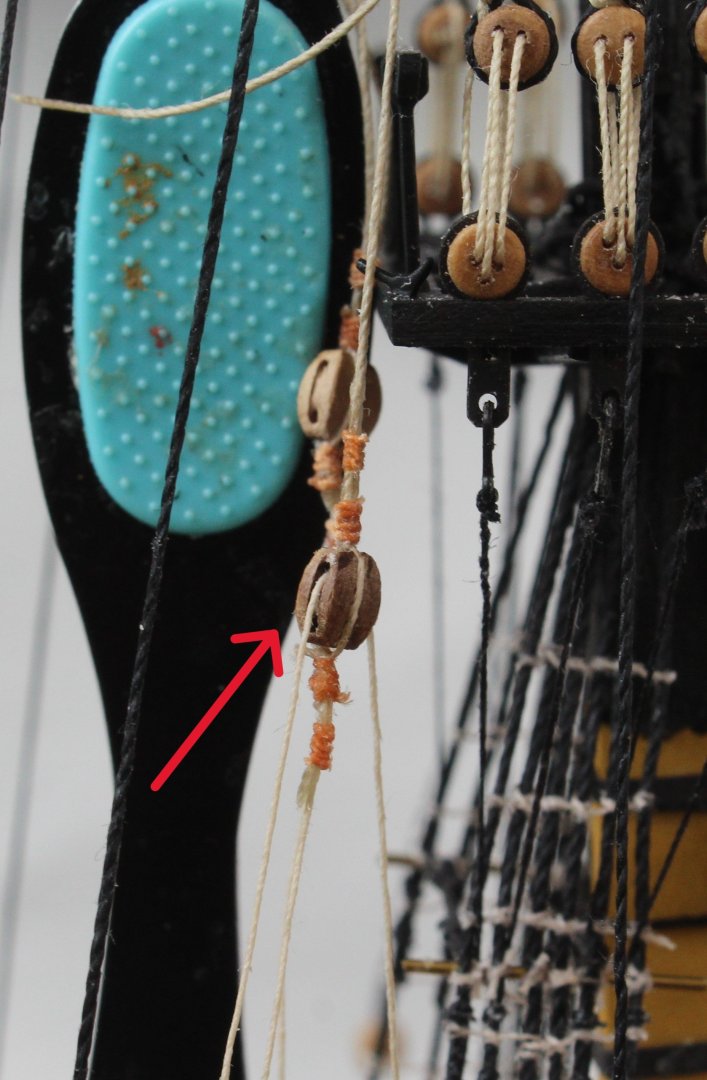
This post details the method I have used to rig the topsail sail tyes. As can be seen in the first two photos below the rigging is fed through a double block on the topsail yard and is the reeved through a single block located on the topsail platform. The rigging is then belayed to the deck via two 5mm single blocks. Starting with the upper 5mm single block the tye thread is held in place as the block seizing is added as shown by the red arrow in the photo below. The lower thread is then added, held in place with a reef knot. The lower thread is then held in the quad hands so the seizing can be added, The block is then reversed so the seizing can be added to the upper tye thread. The completed upper 5mm block is shown in the next photo. These threads are then reeved through the 3mm single block and the 4mm double block, the 4mm block is shown in the photo below. A length of thread is then seized around the lower 5mm single block. An eyebolt is then added to the thread, using a template to set the distance between the eyebolt and single block. The next set of photos shows the completed rigging.


- 241 replies
-
- 8
-
-
- Vanguarrd Models
- Harpy
- (and 1 more)