HOLIDAY DONATION DRIVE - SUPPORT MSW - DO YOUR PART TO KEEP THIS GREAT FORUM GOING! (89 donations so far out of 49,000 members - C'mon guys!)
×


Glenn-UK
-
Posts
3,163 -
Joined
-
Last visited
Content Type
Profiles
Forums
Gallery
Events
Everything posted by Glenn-UK
-
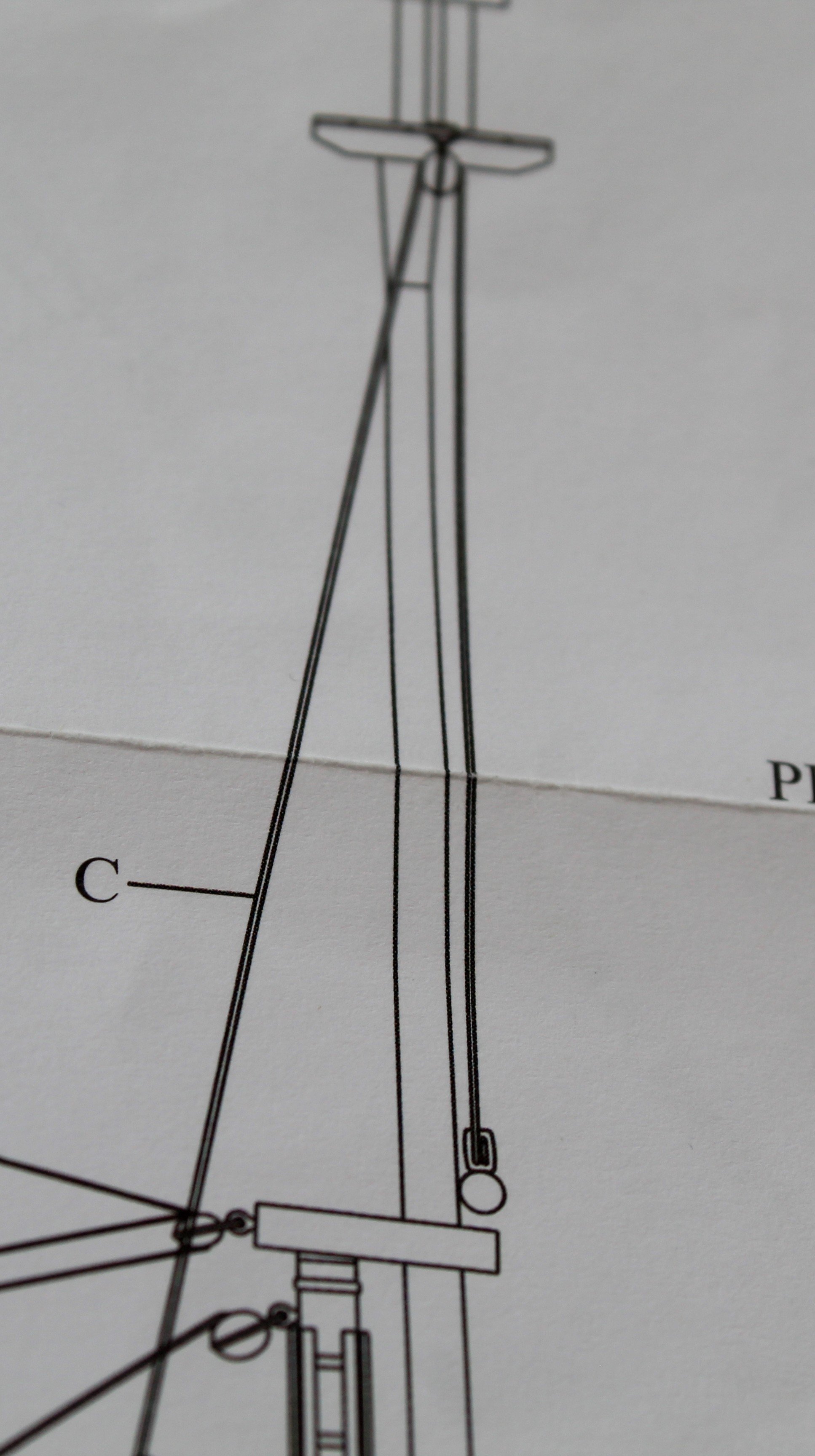
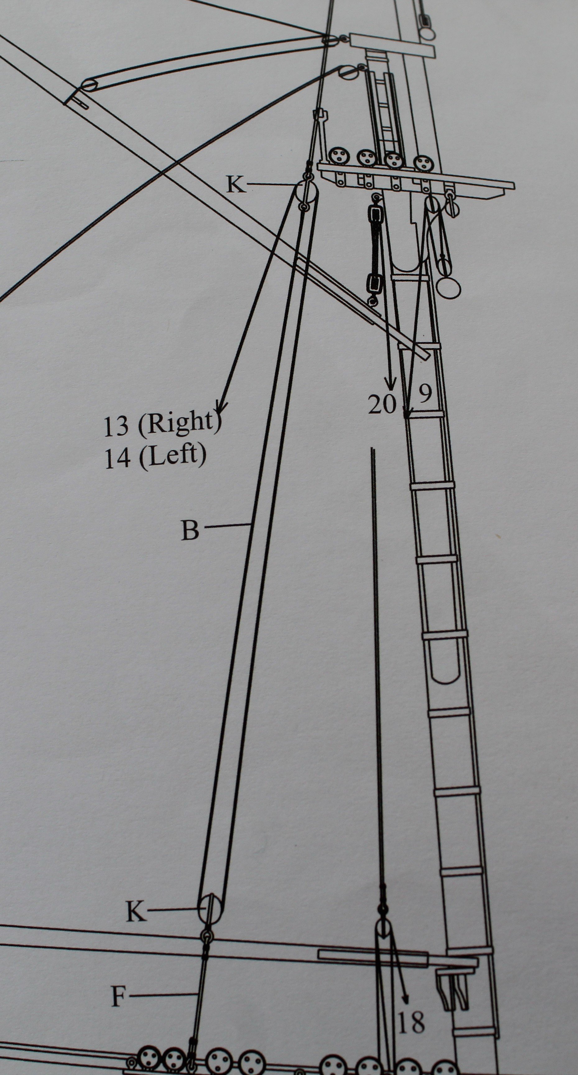
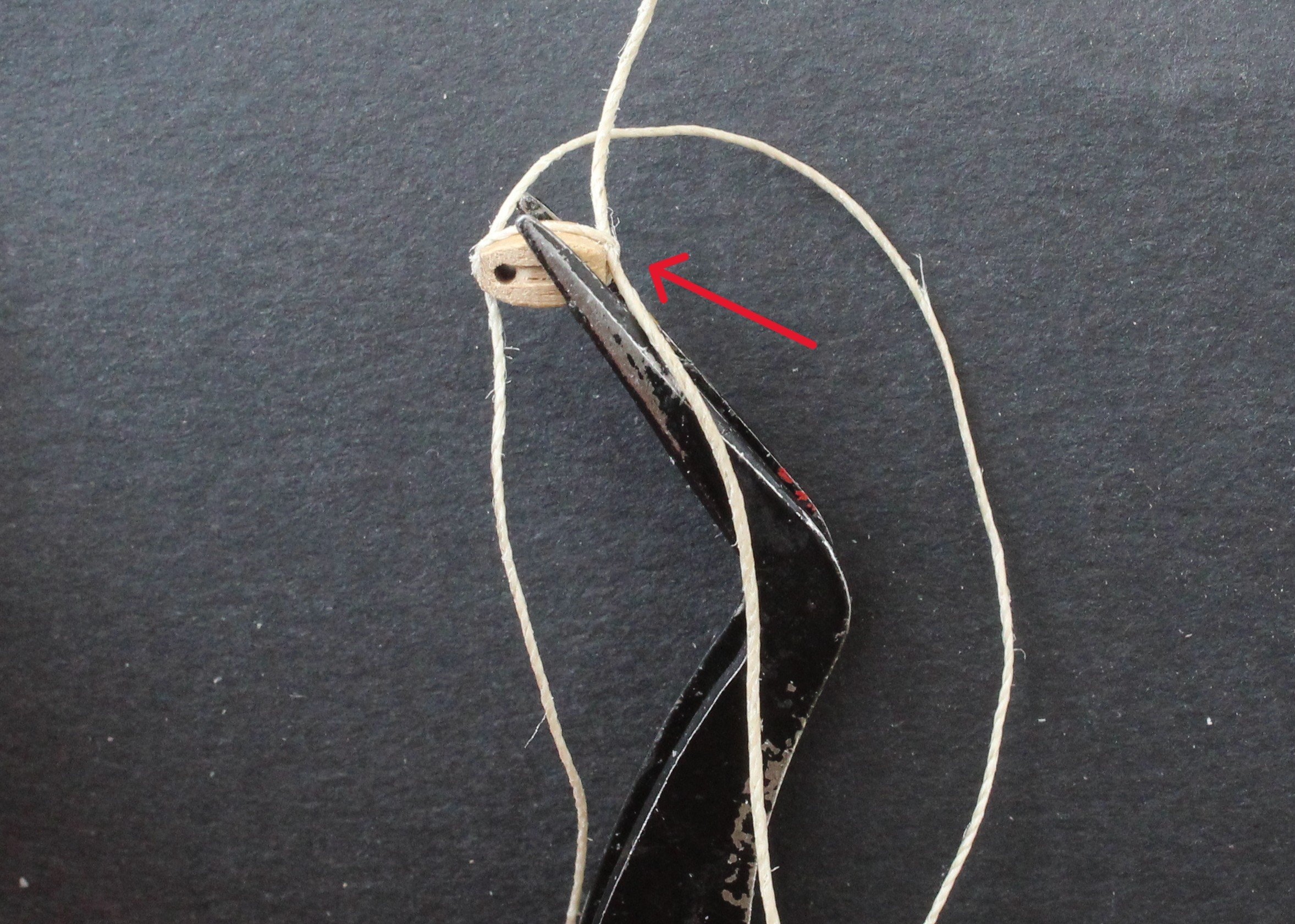
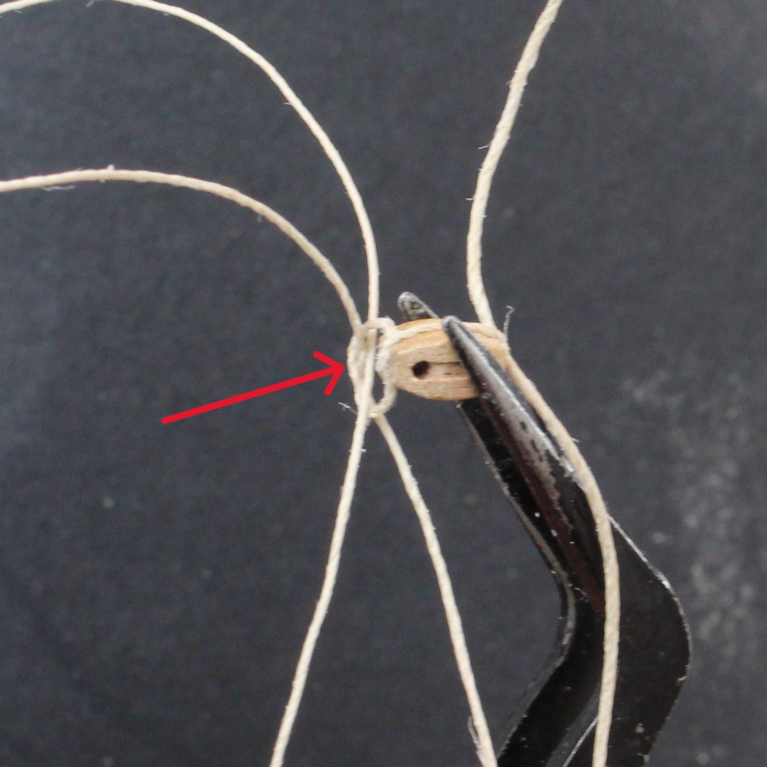
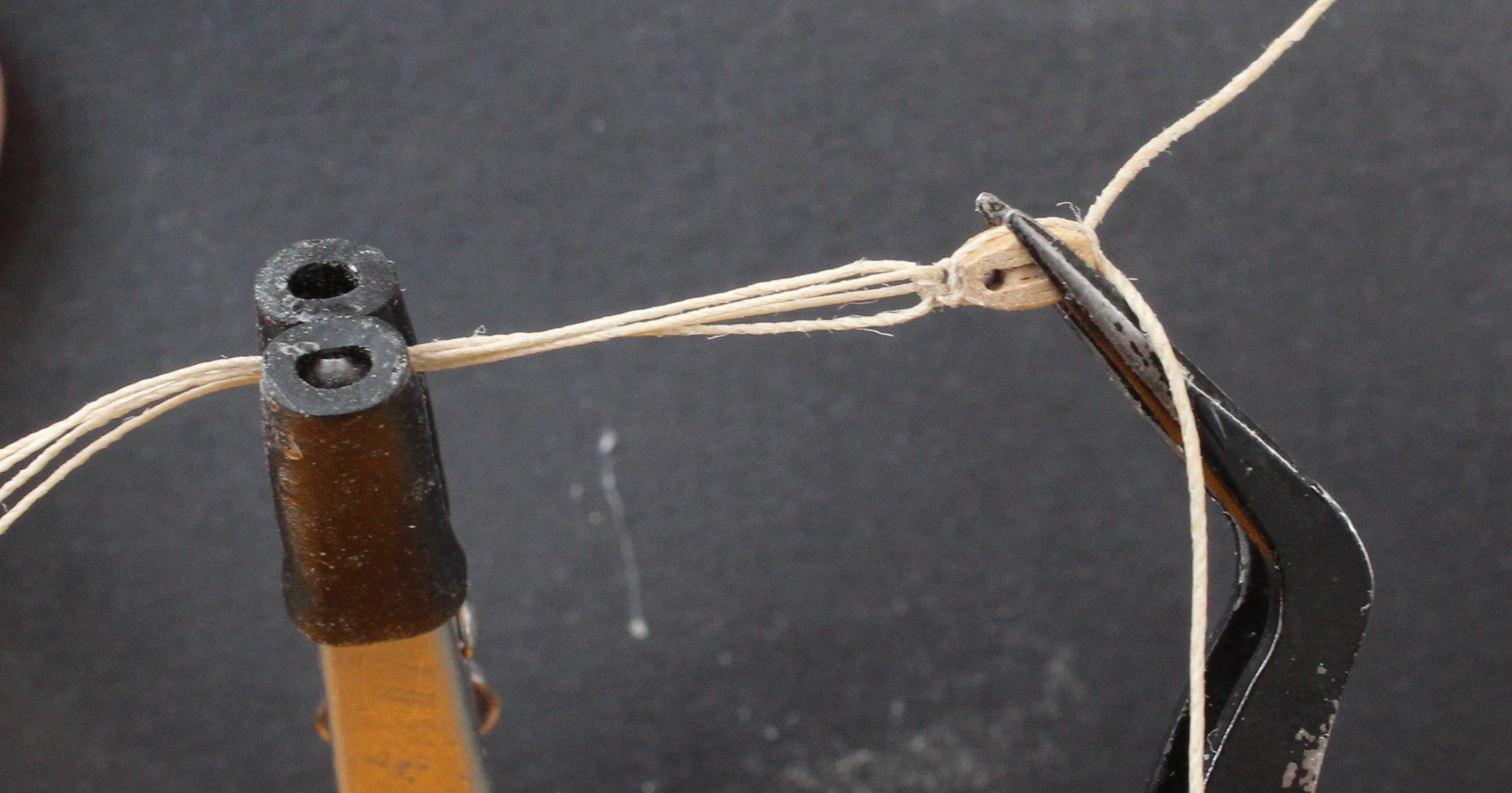
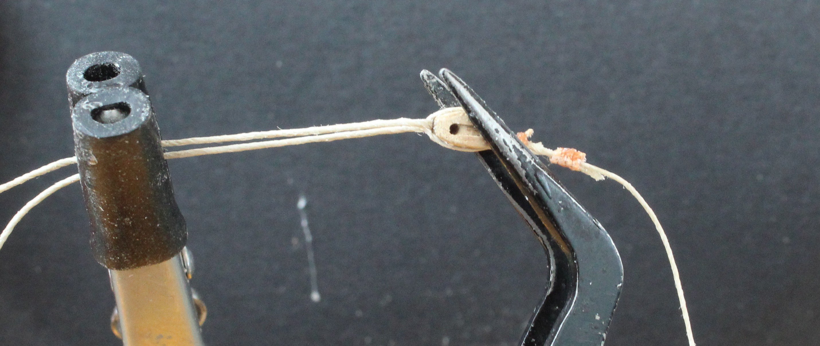
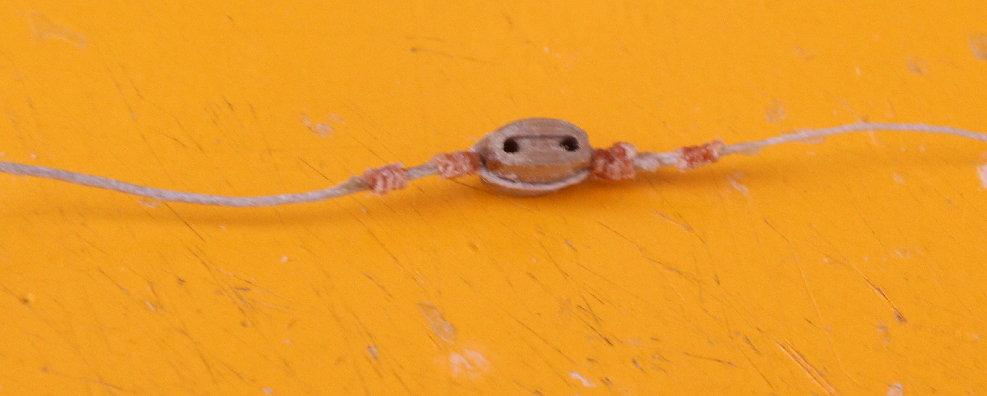
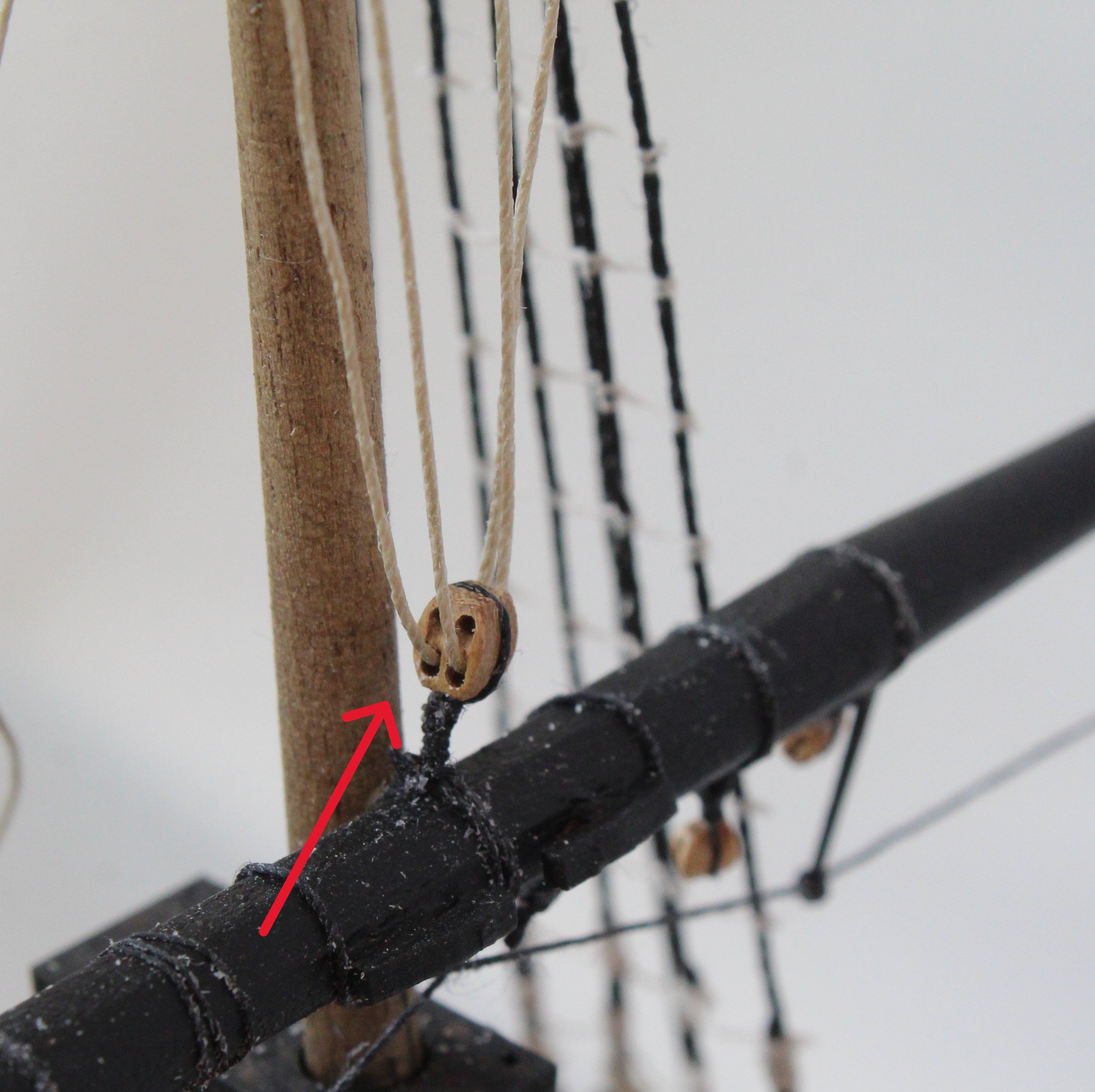
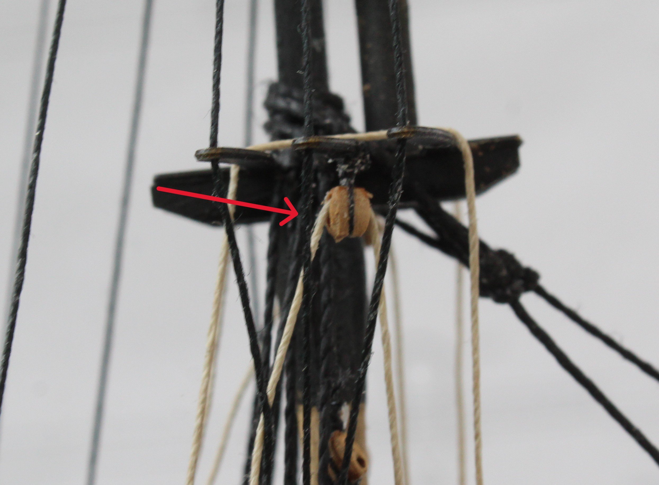
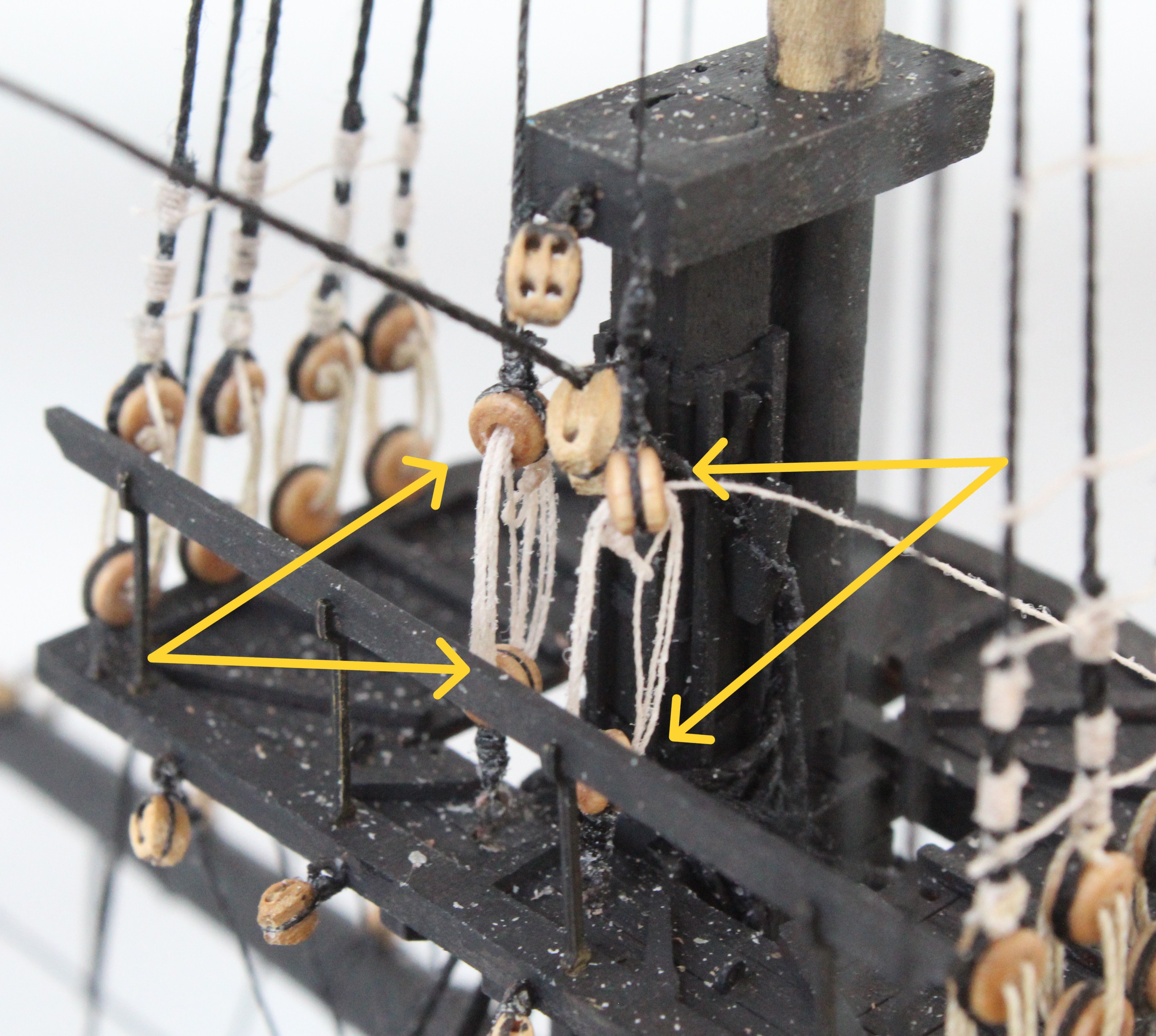
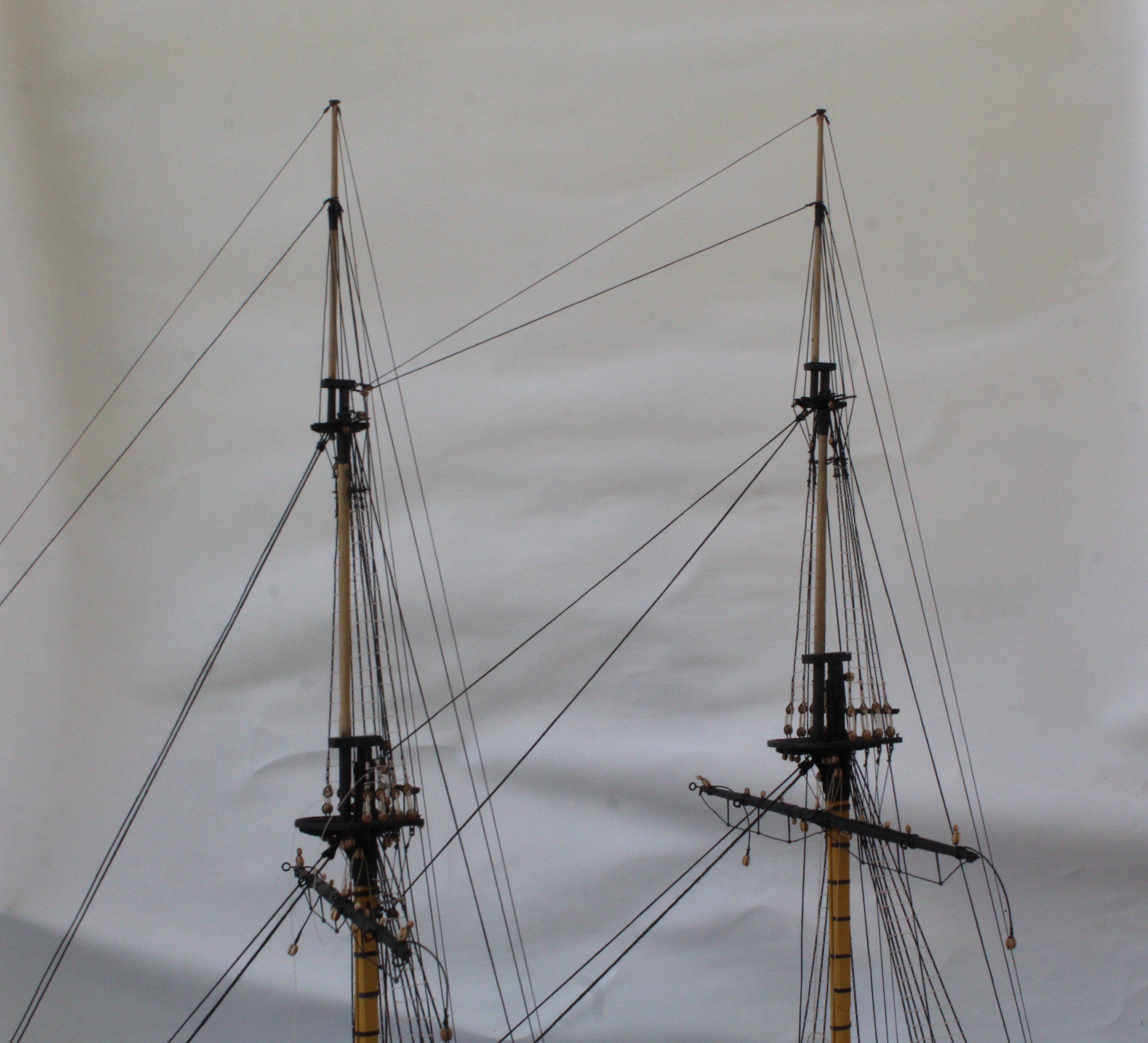
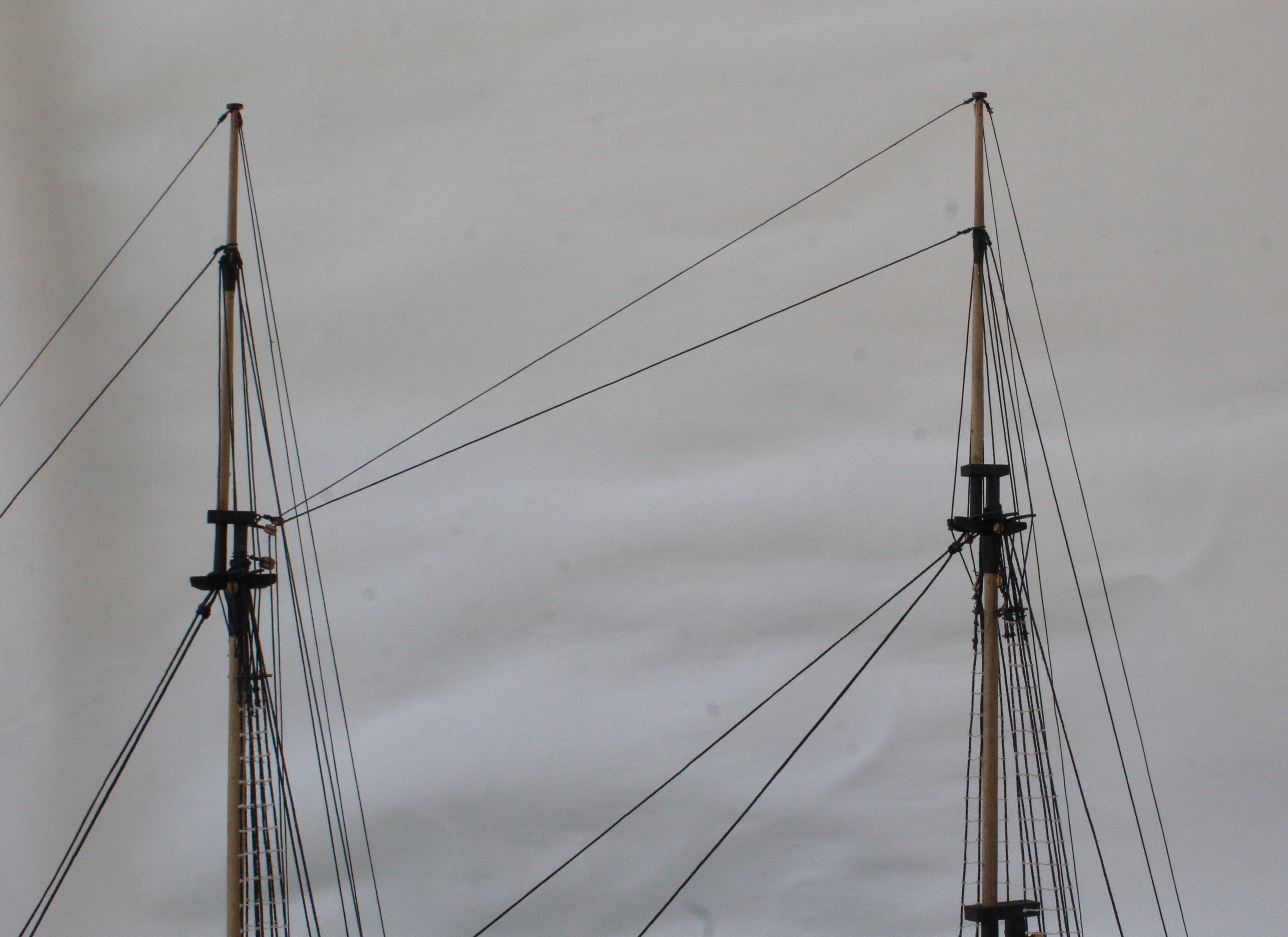
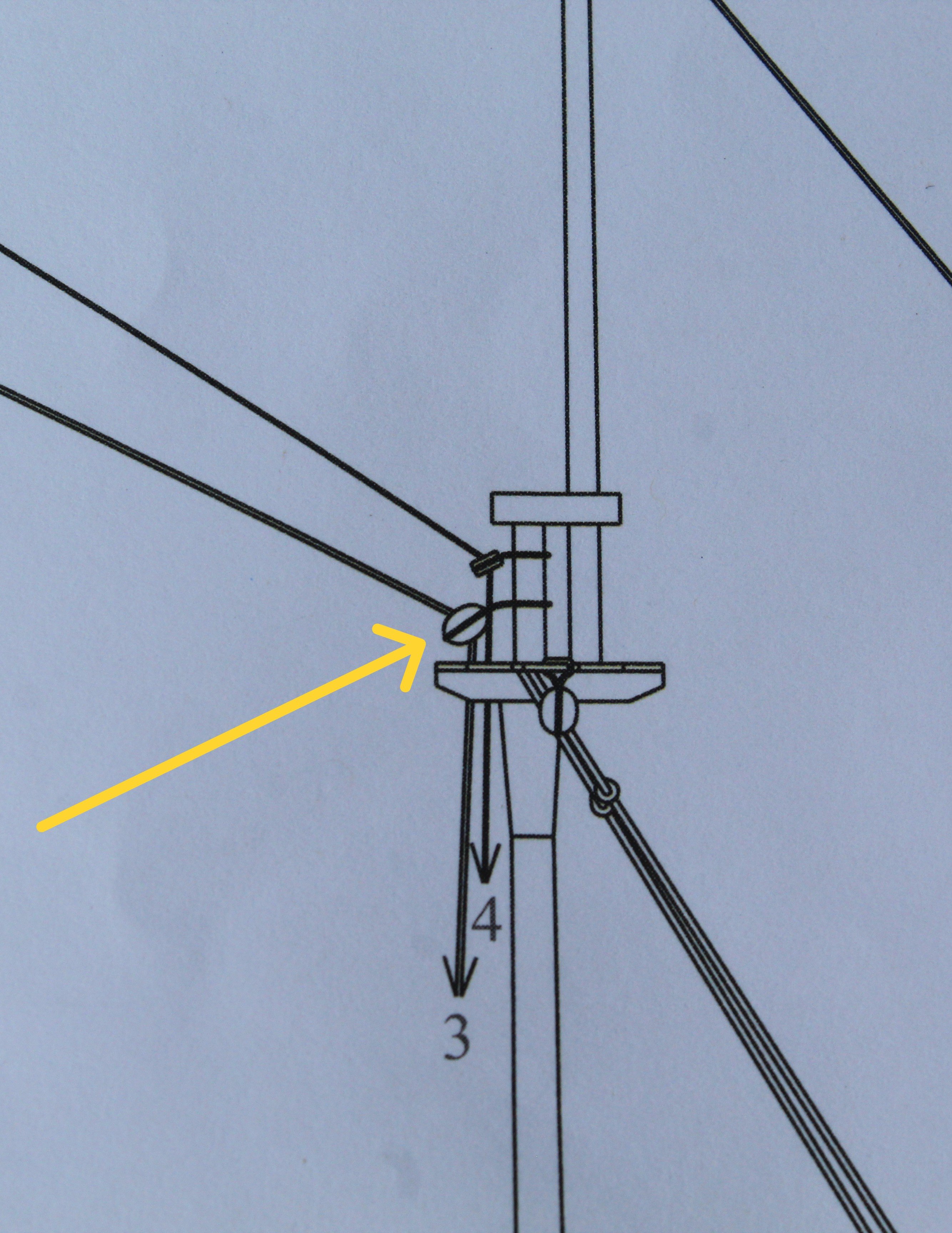
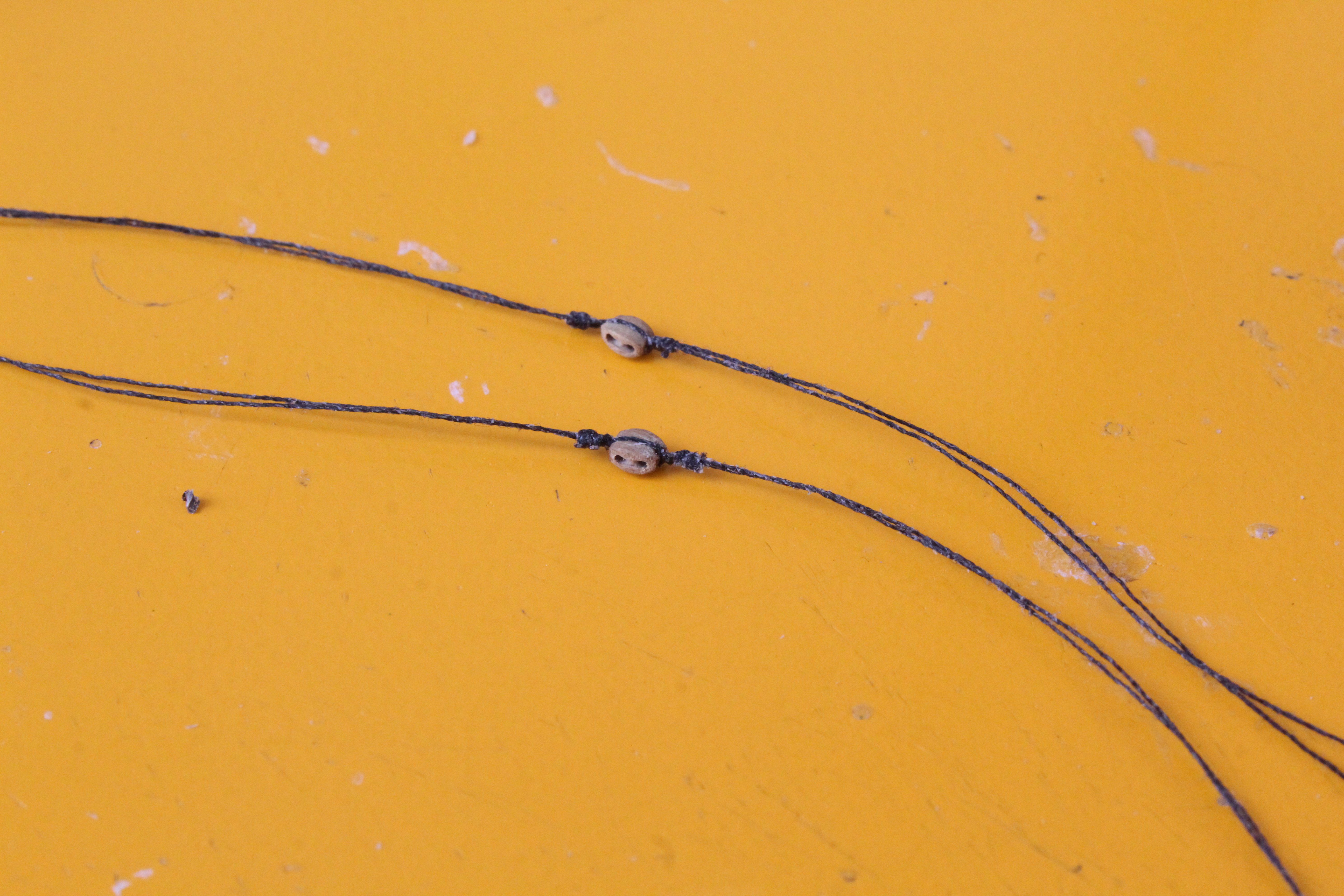
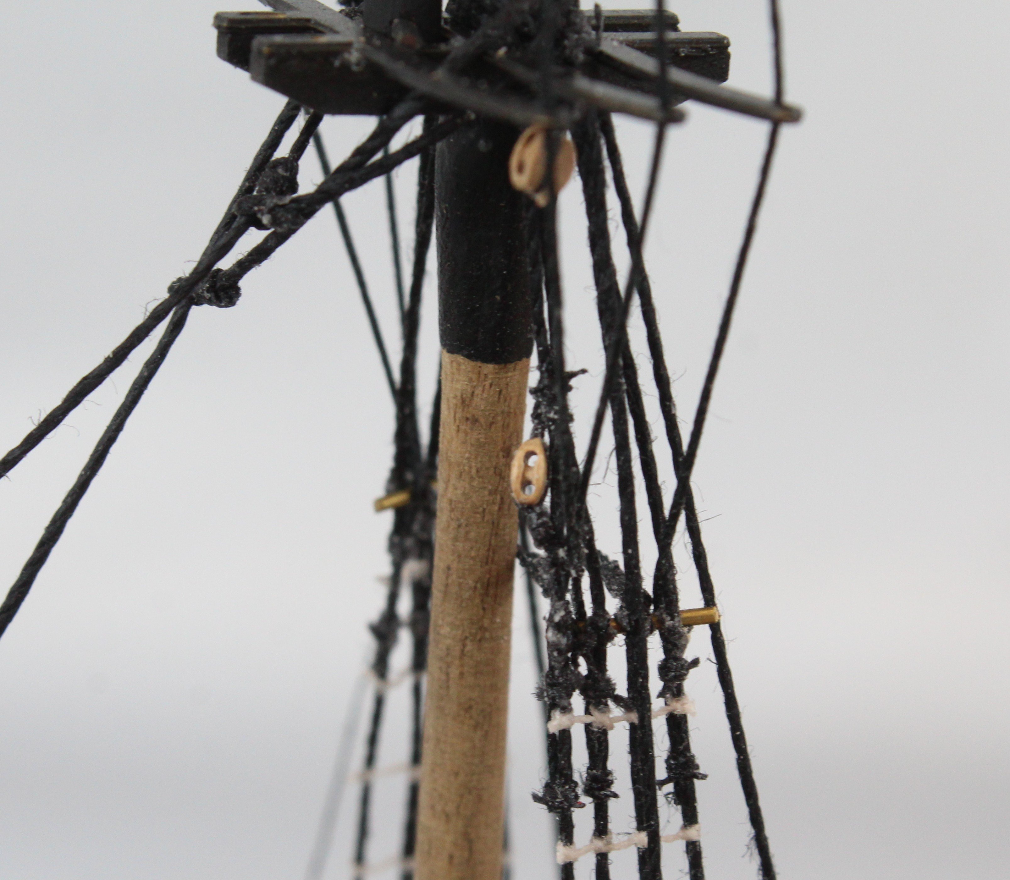
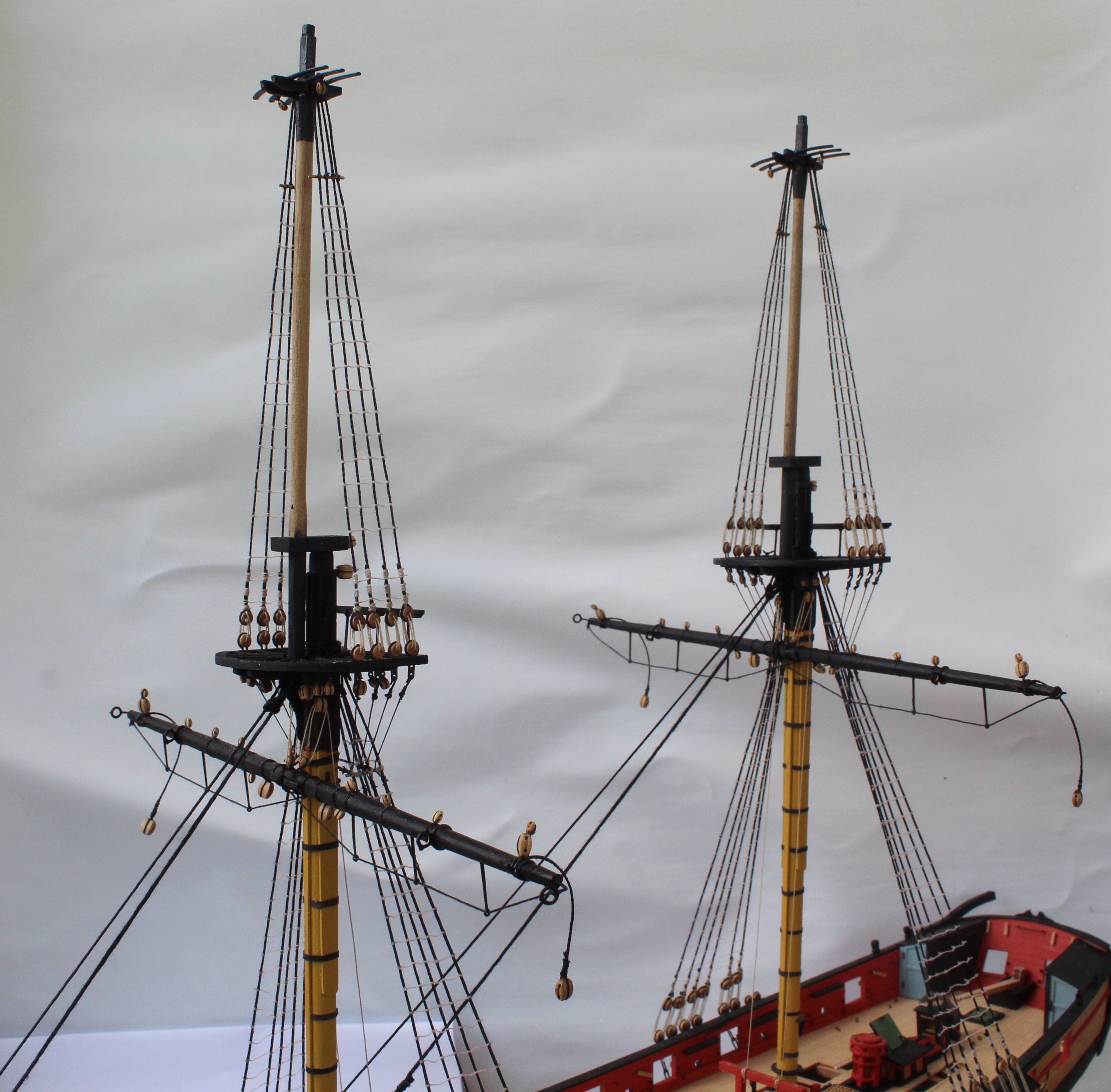
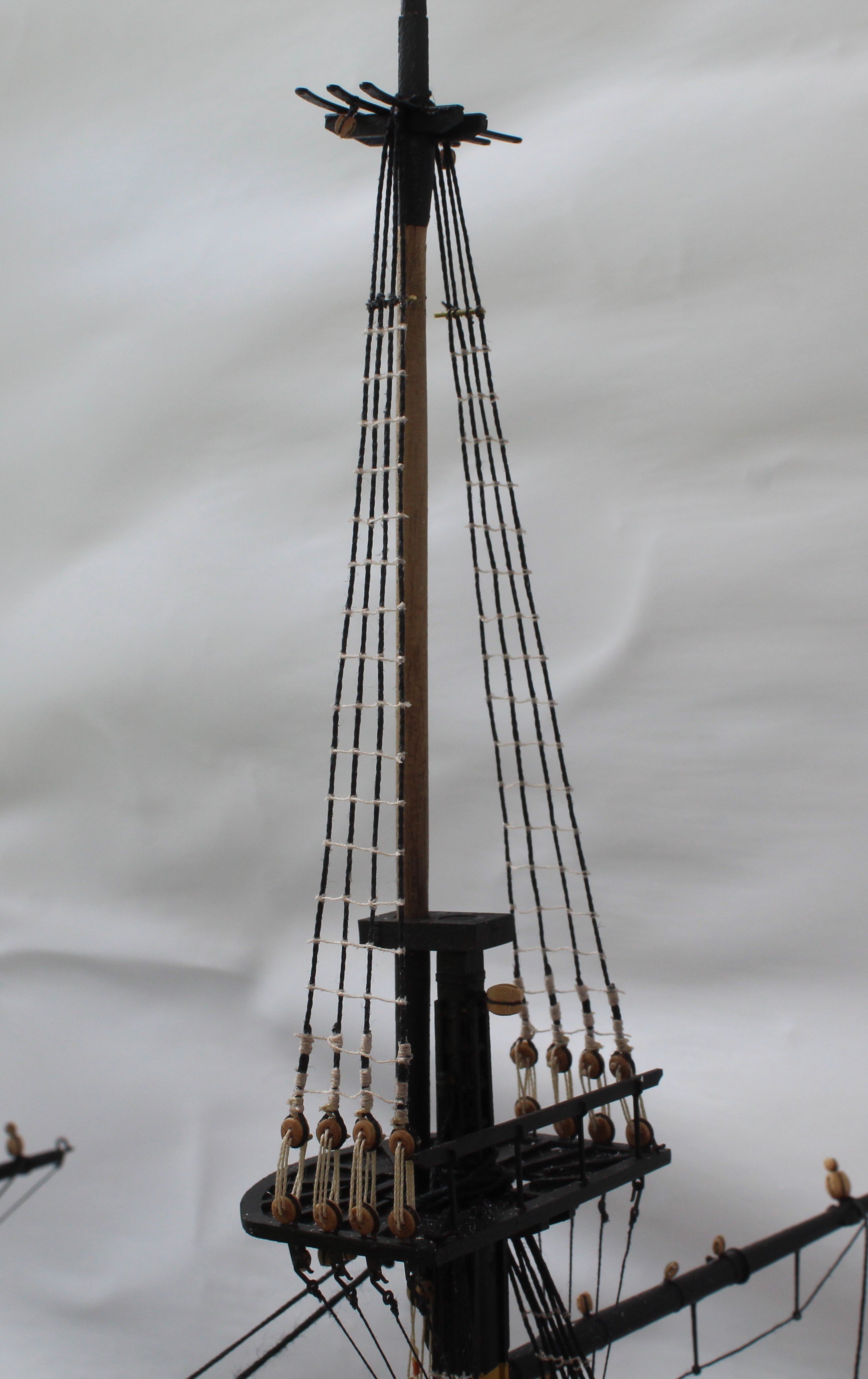
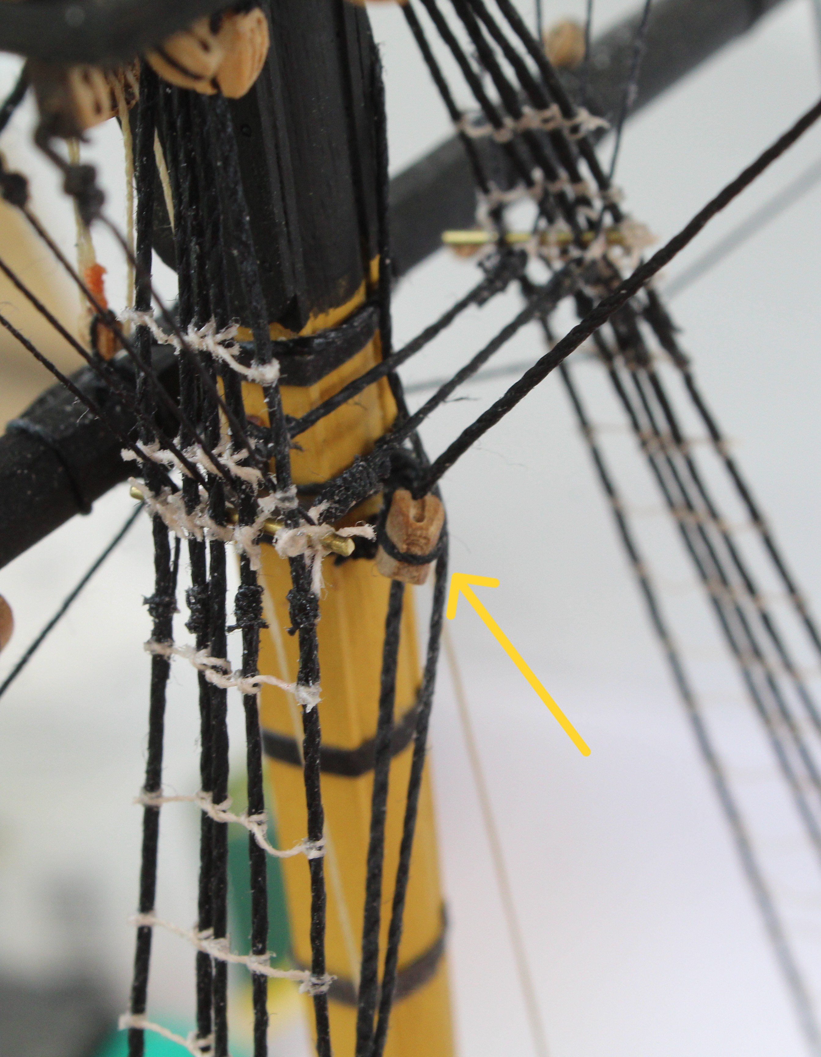
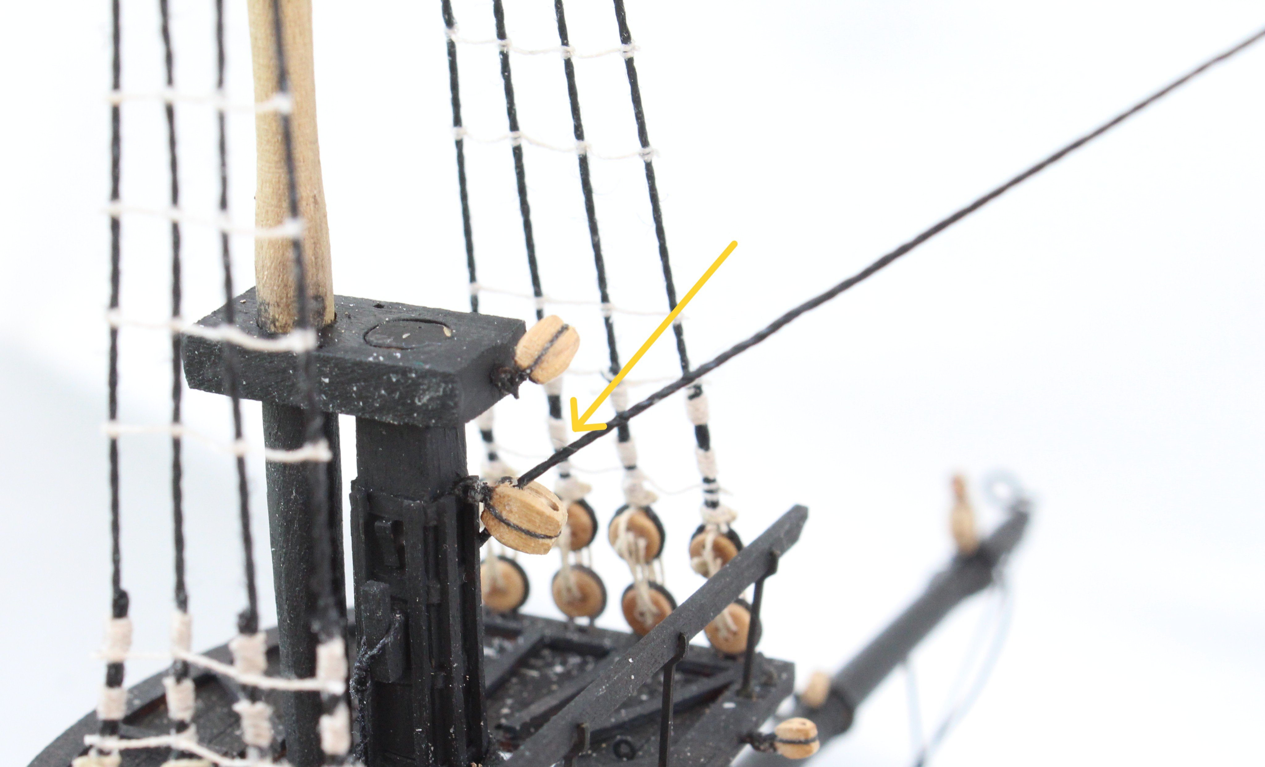
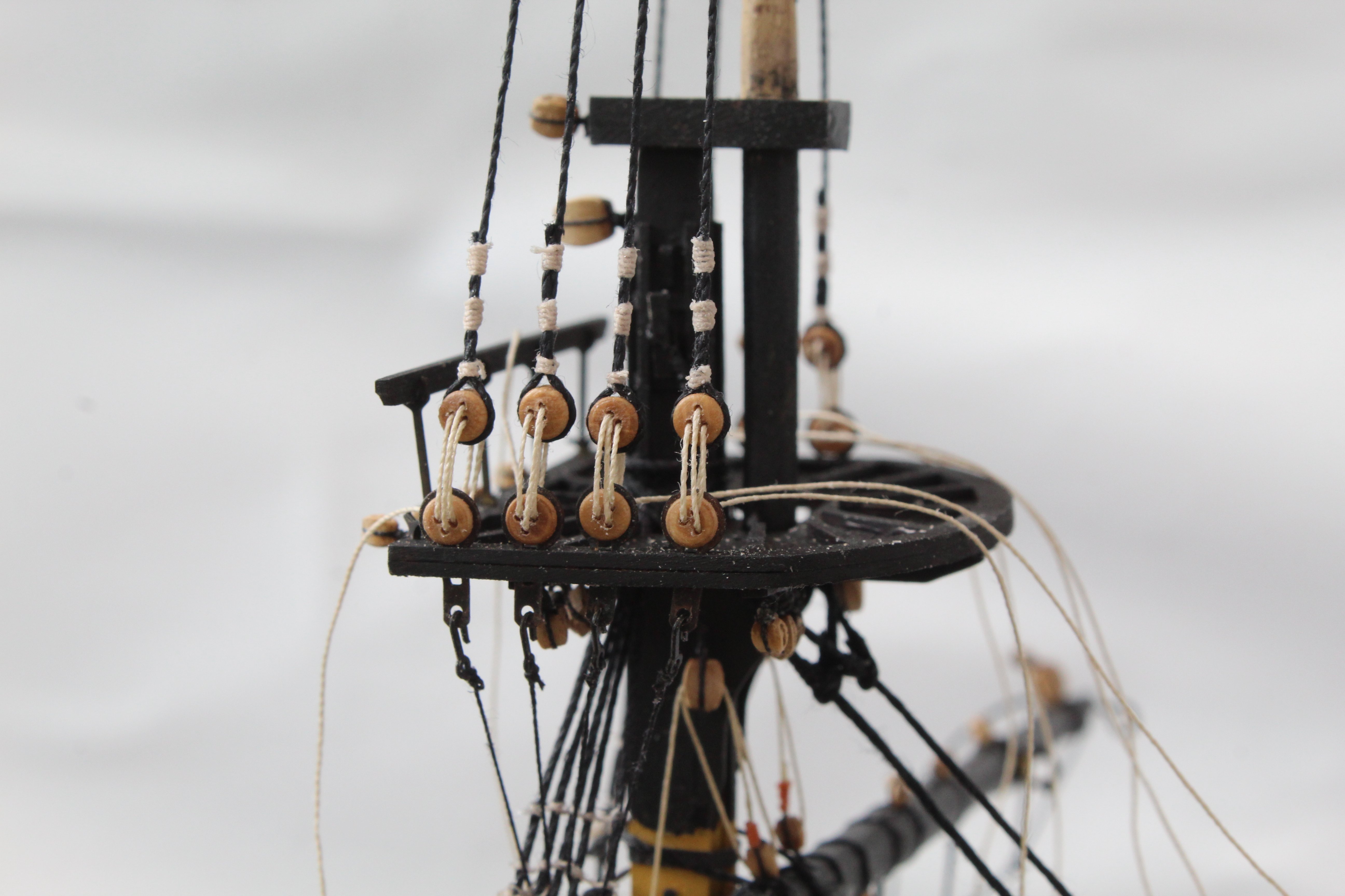
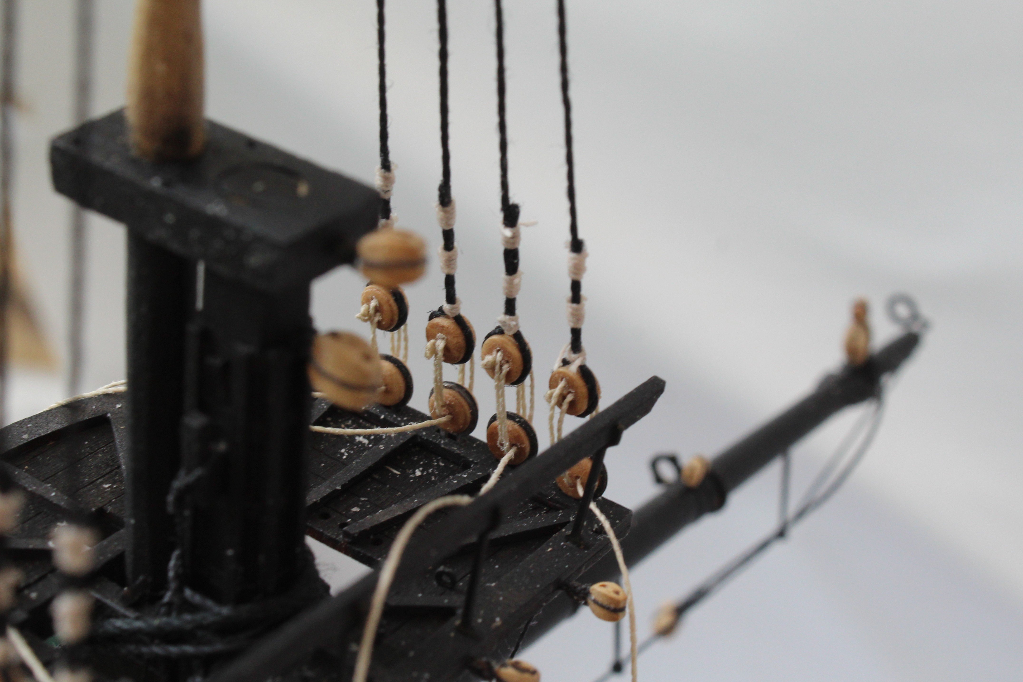
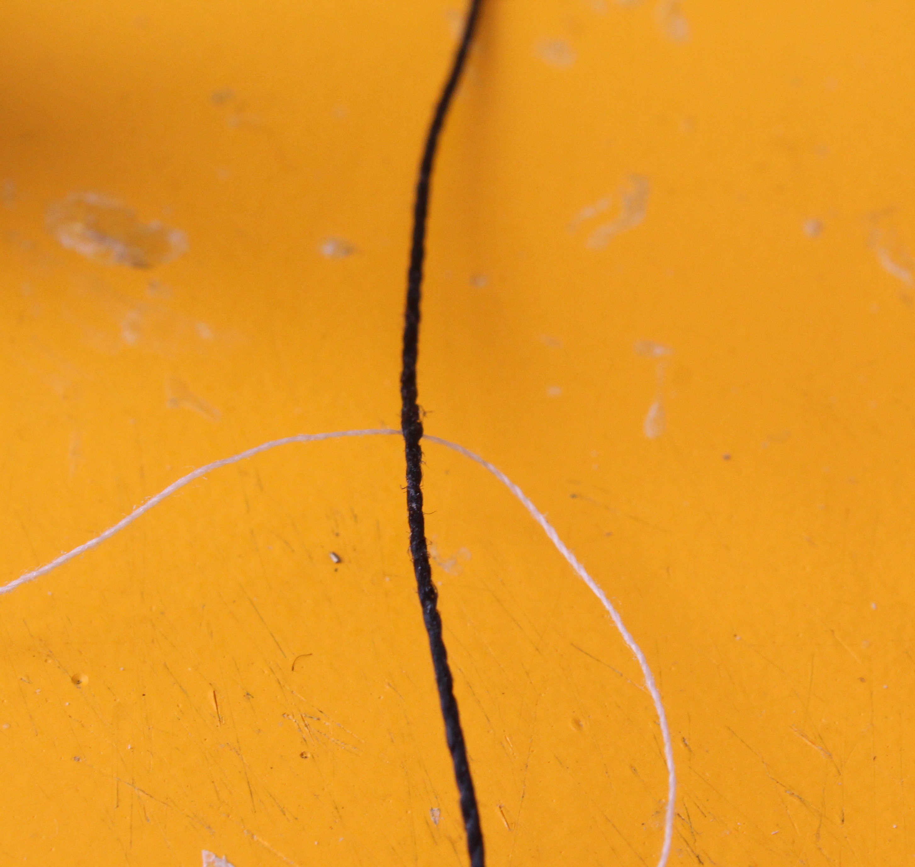
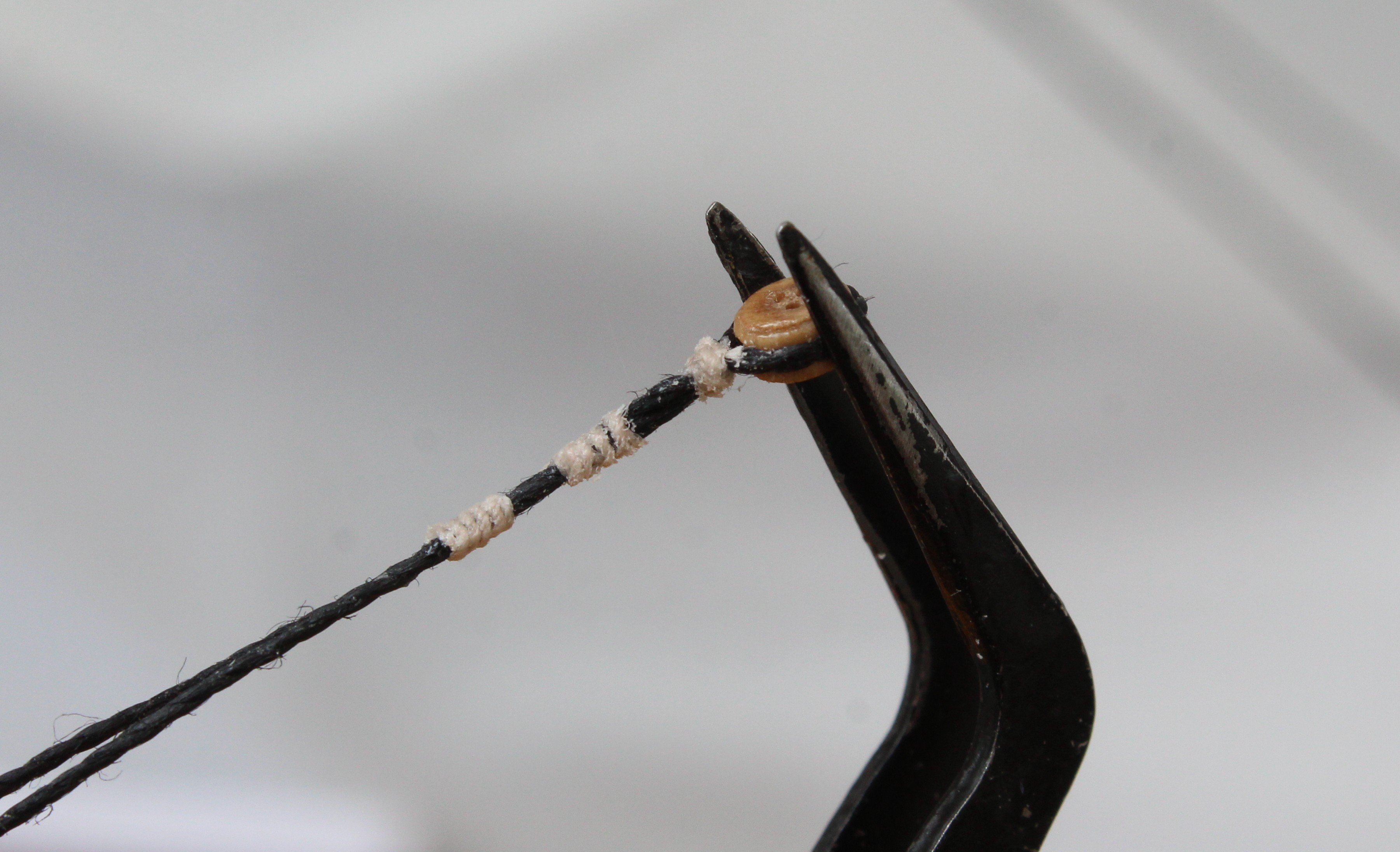
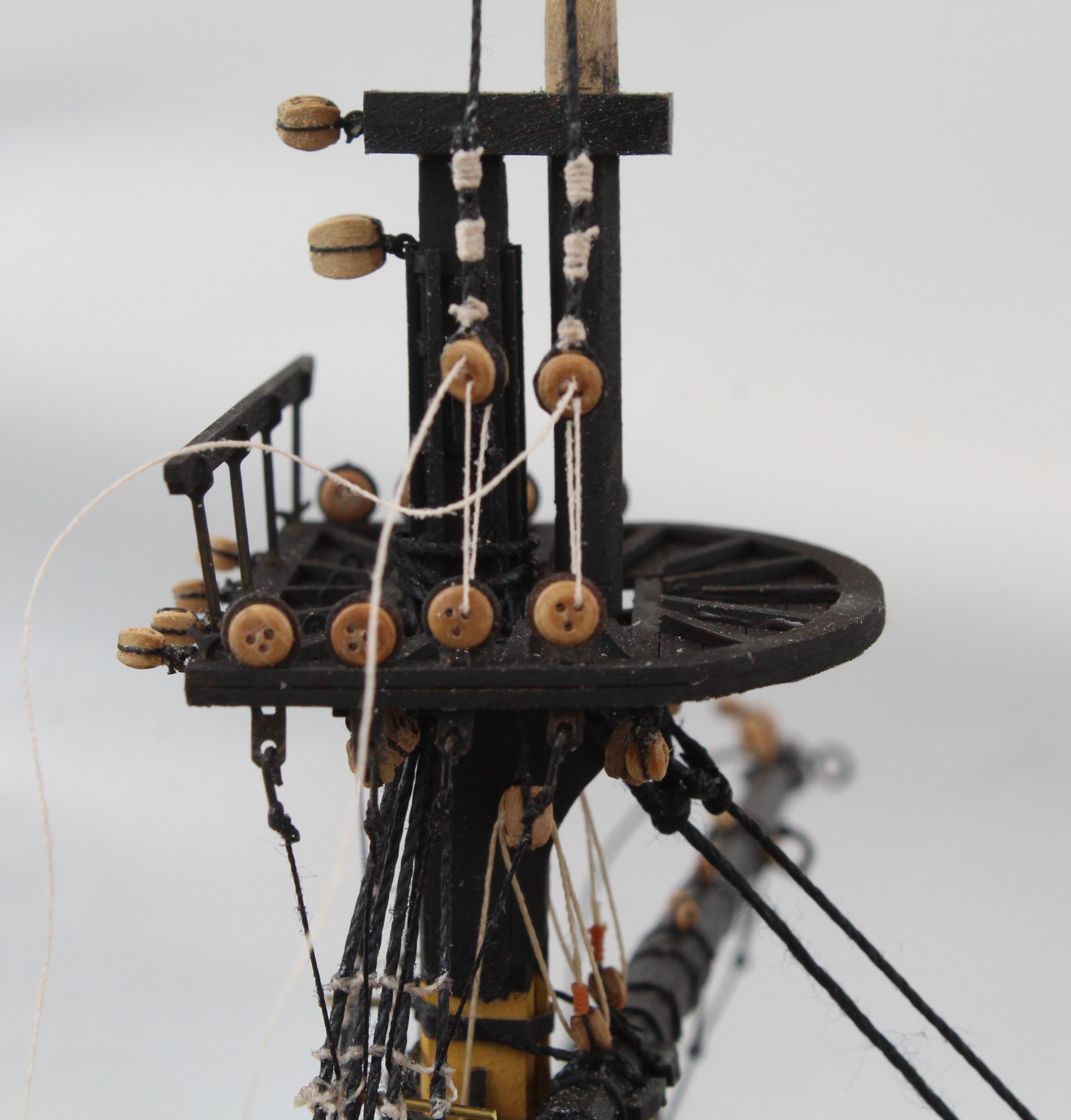
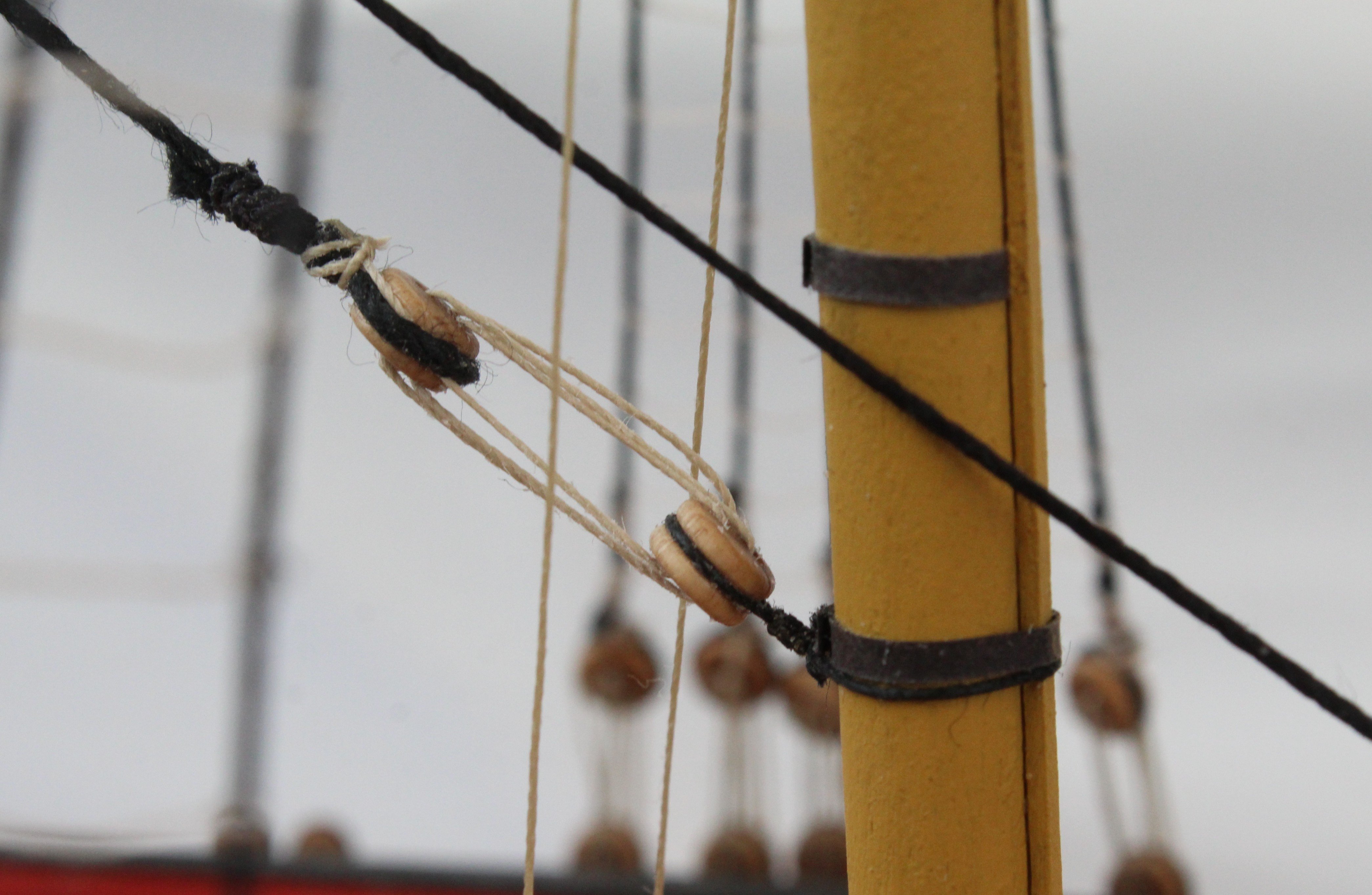
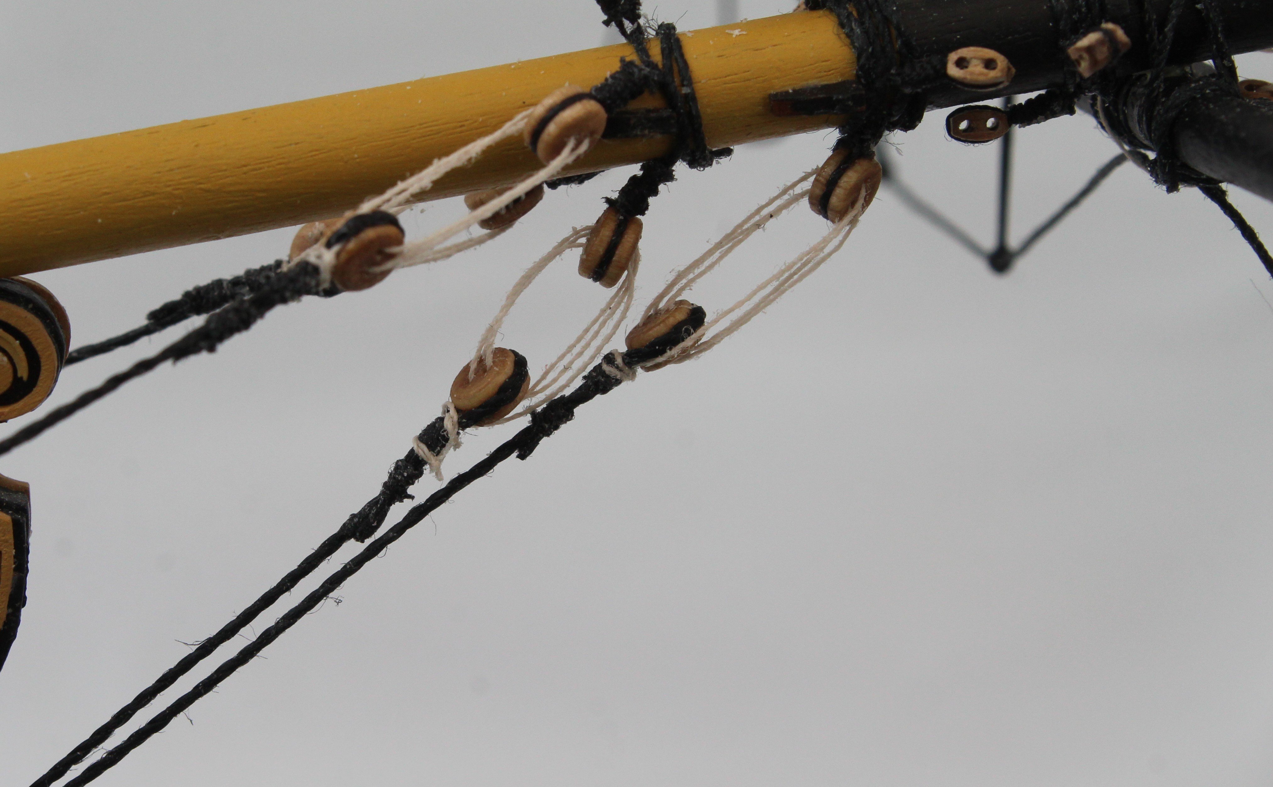
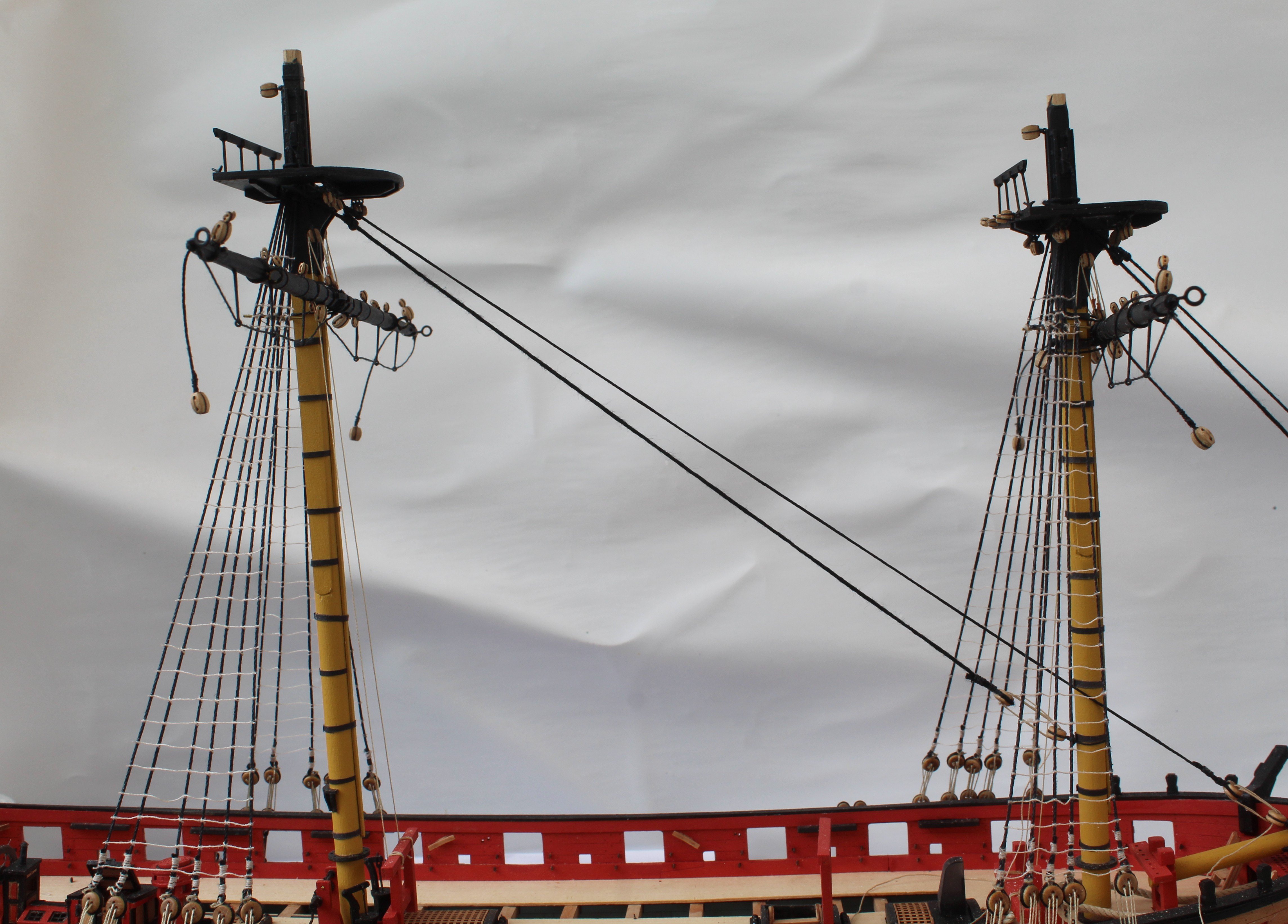
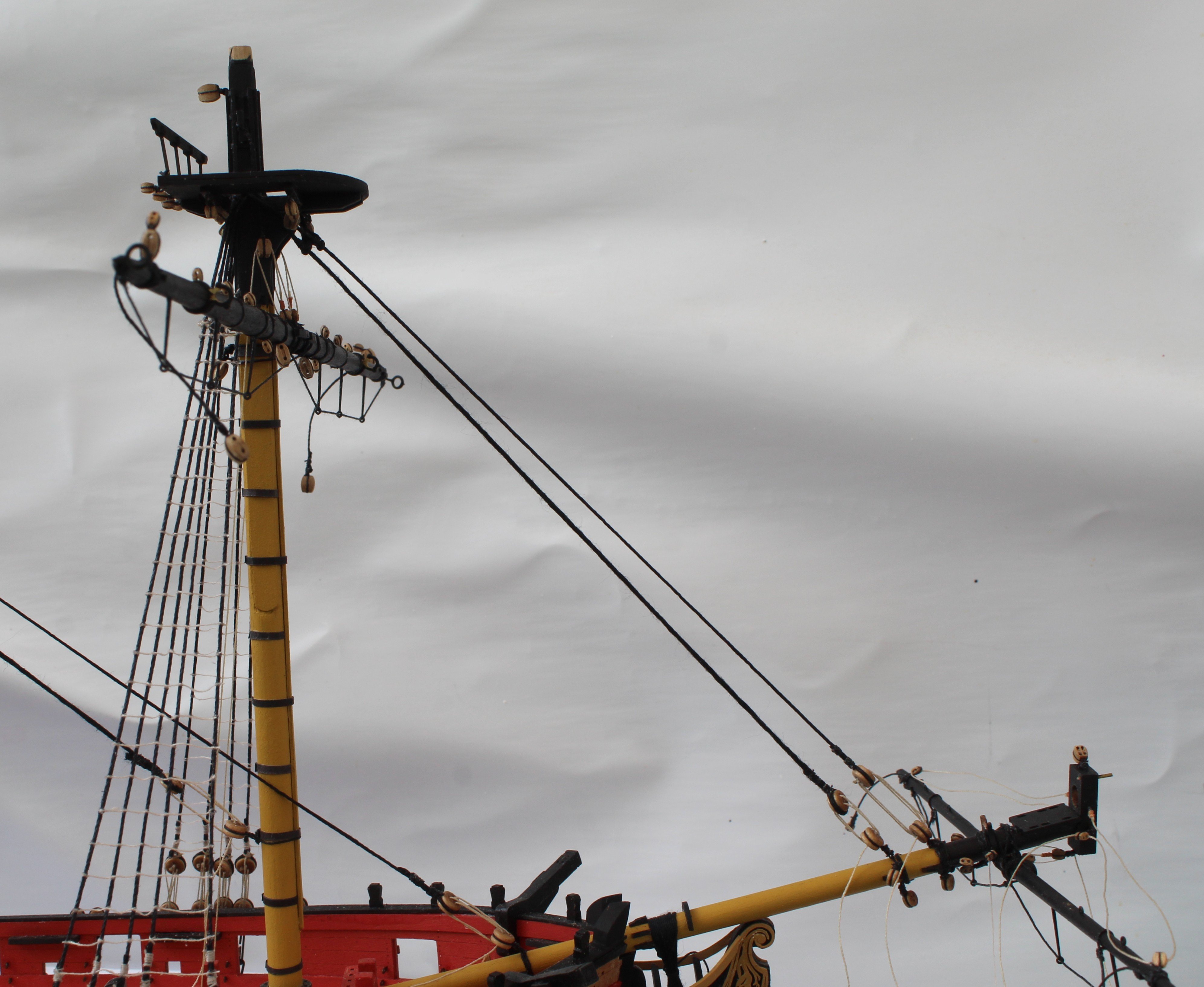
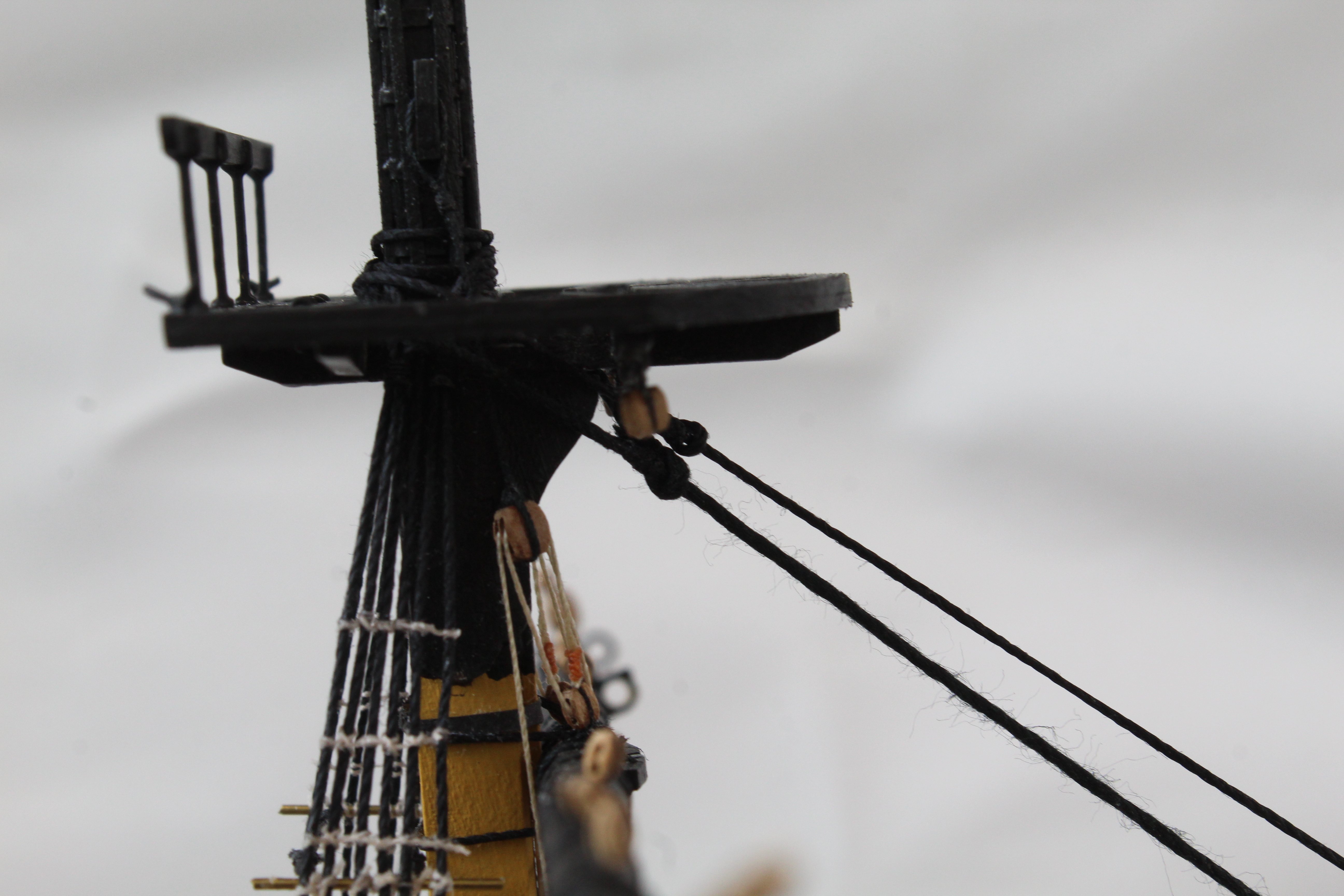
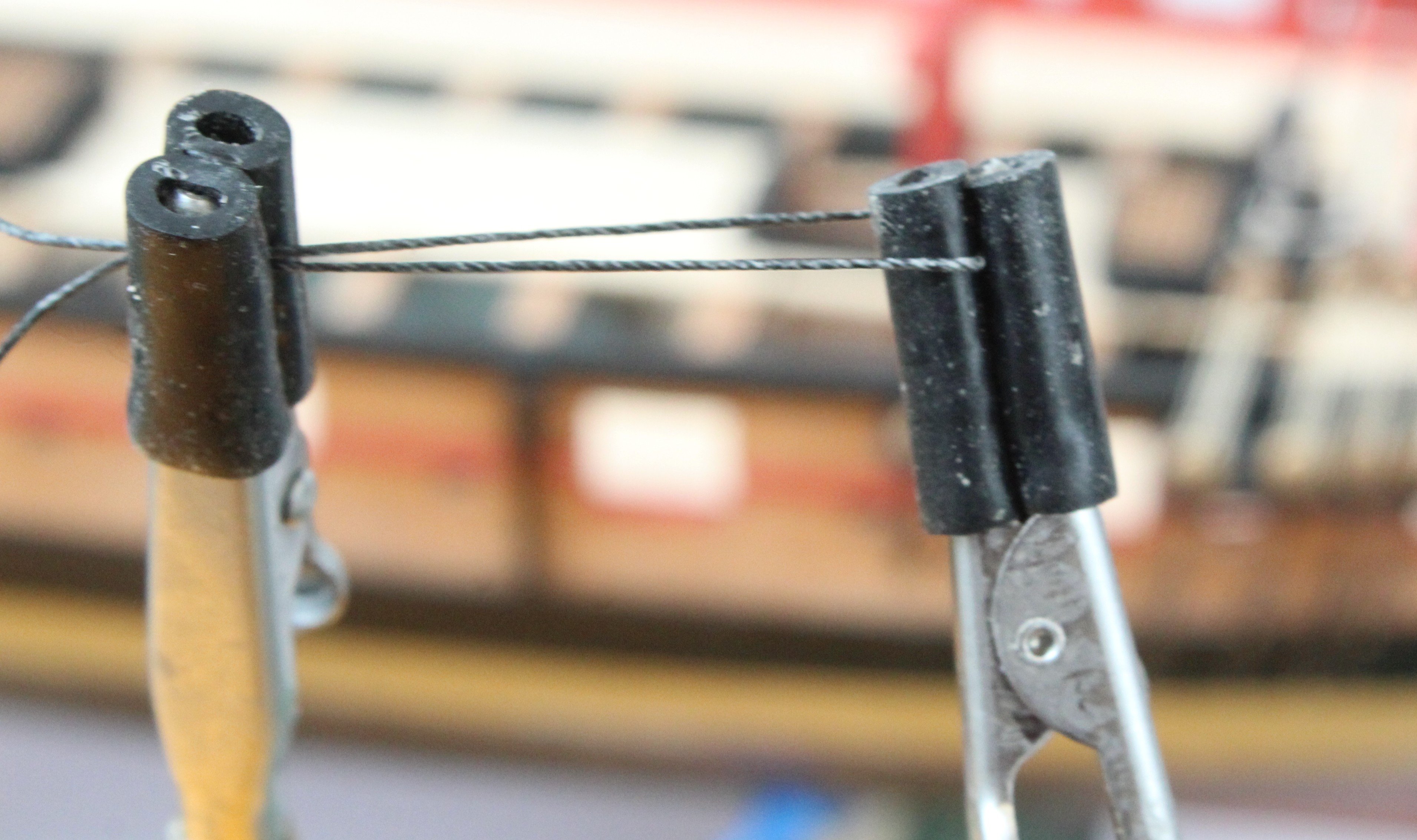
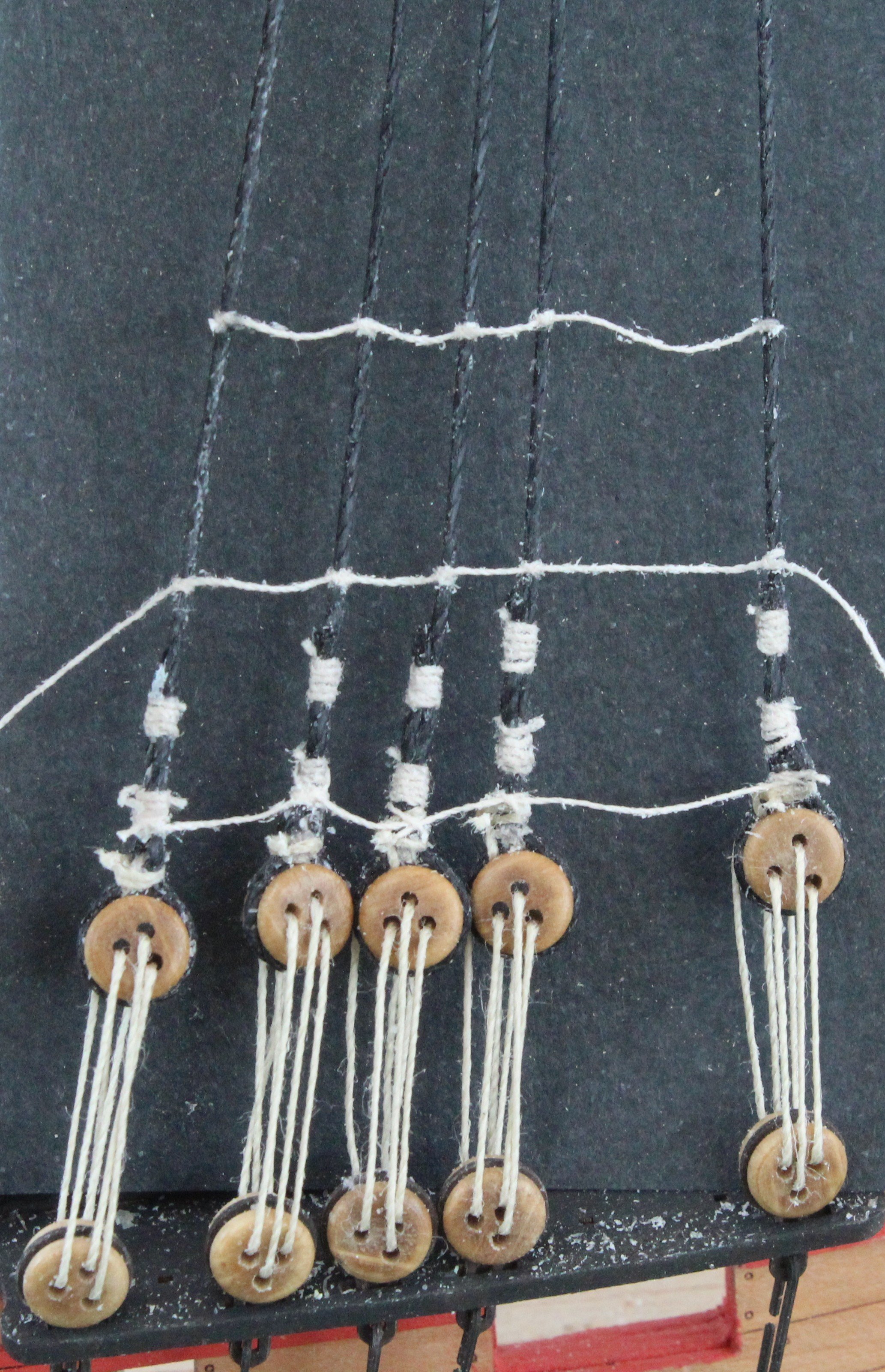
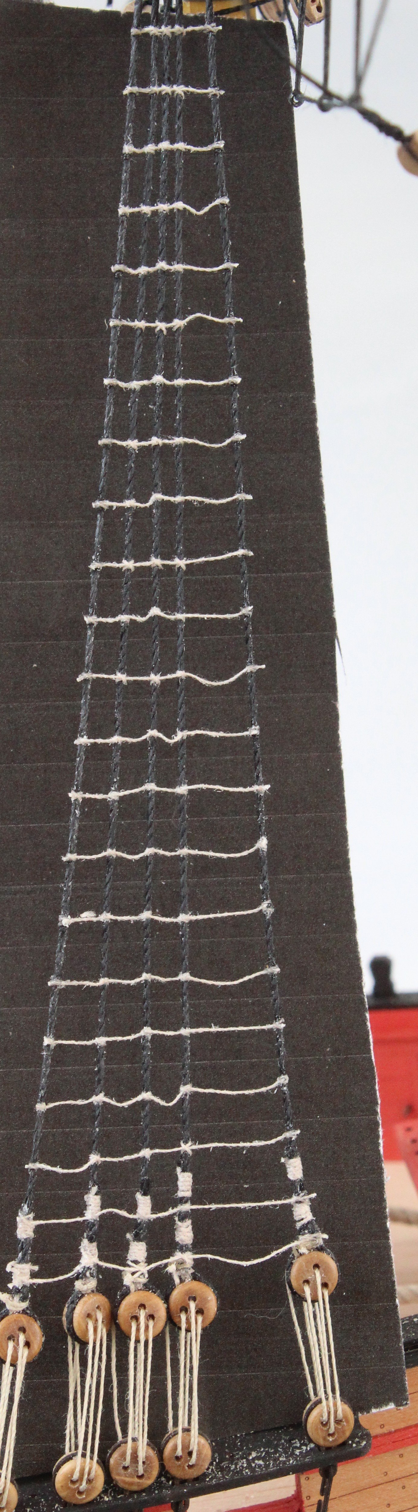
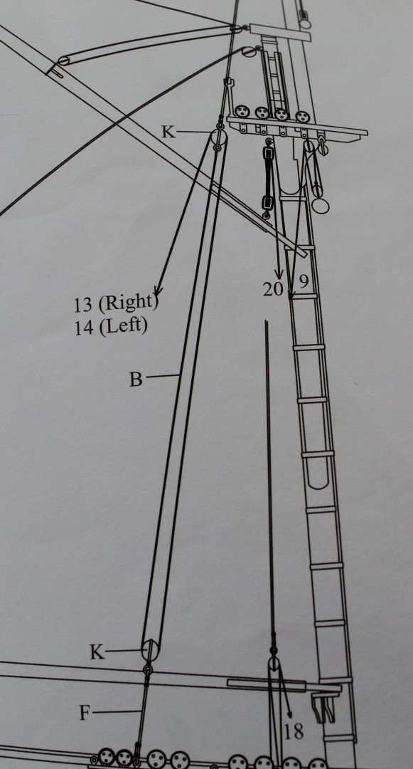
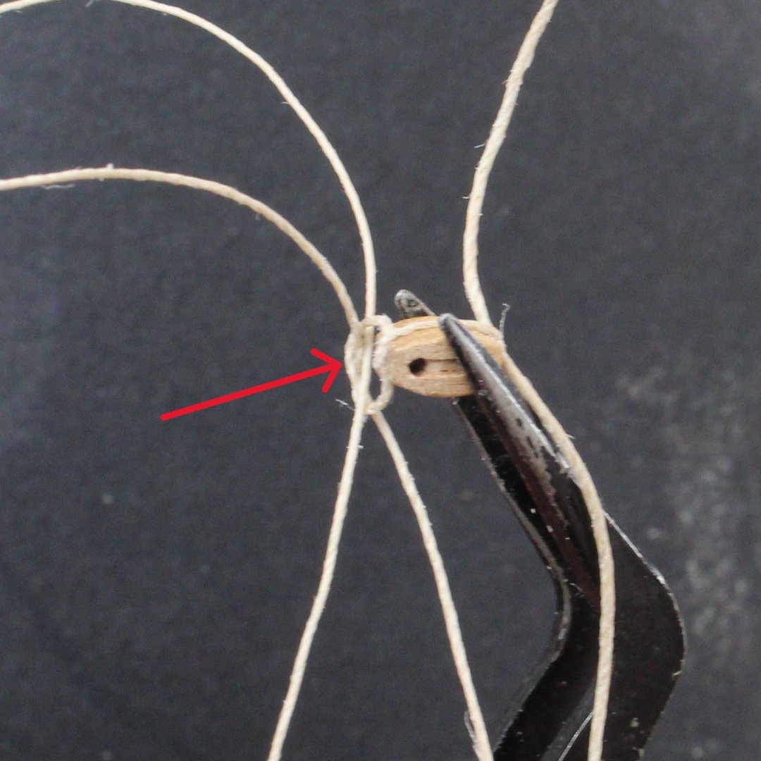
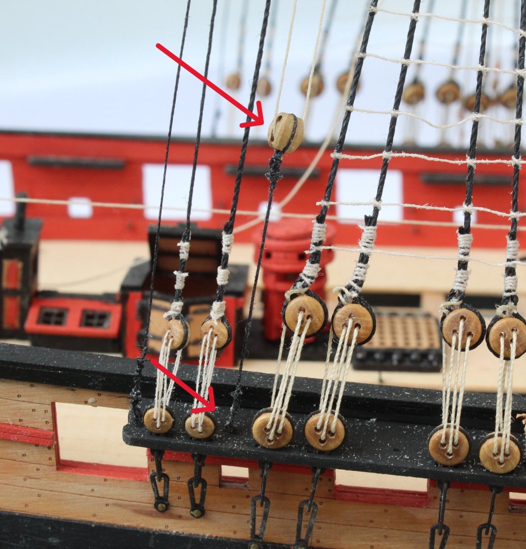
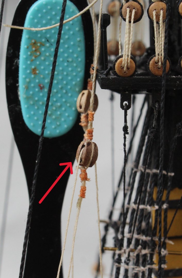
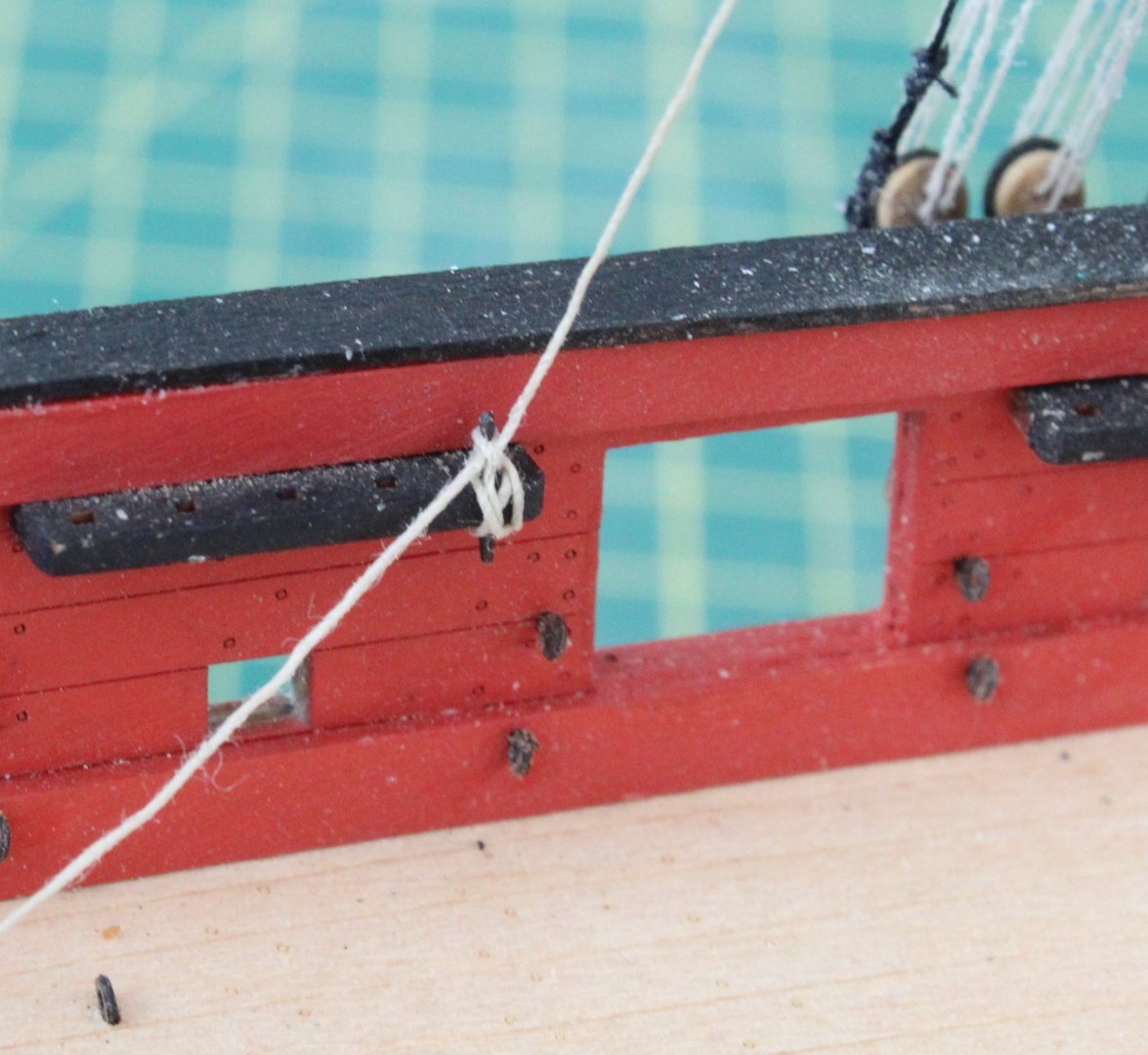
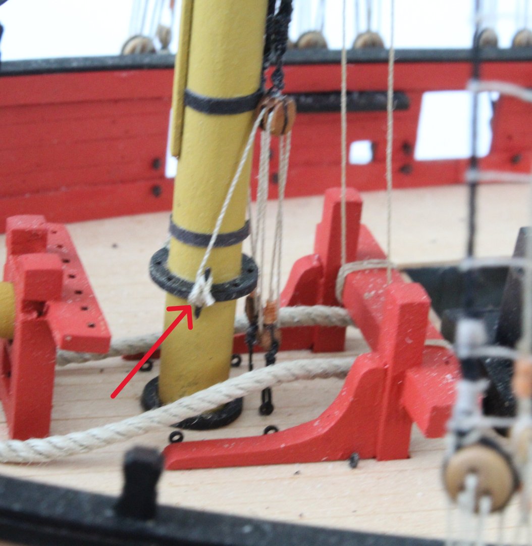
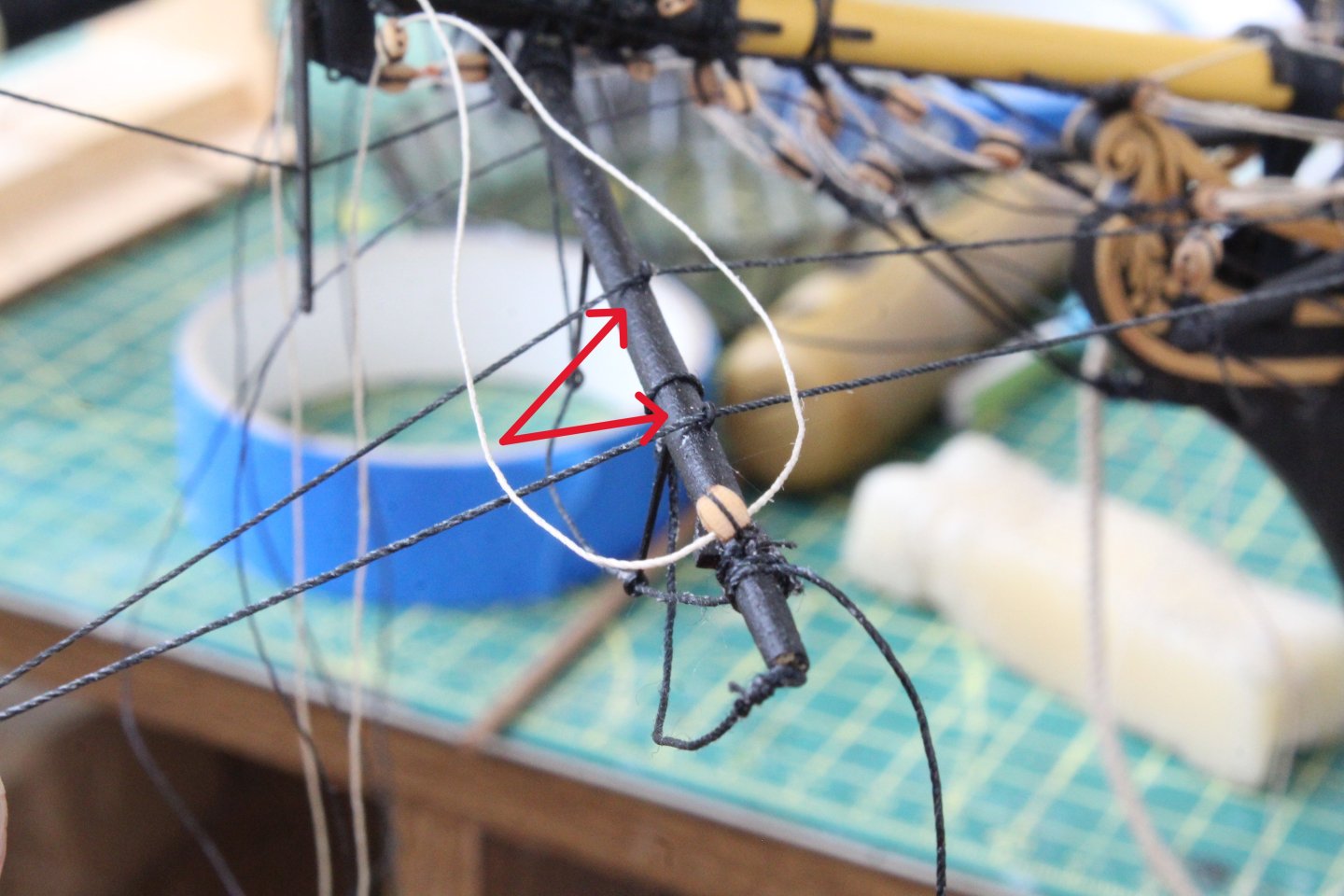
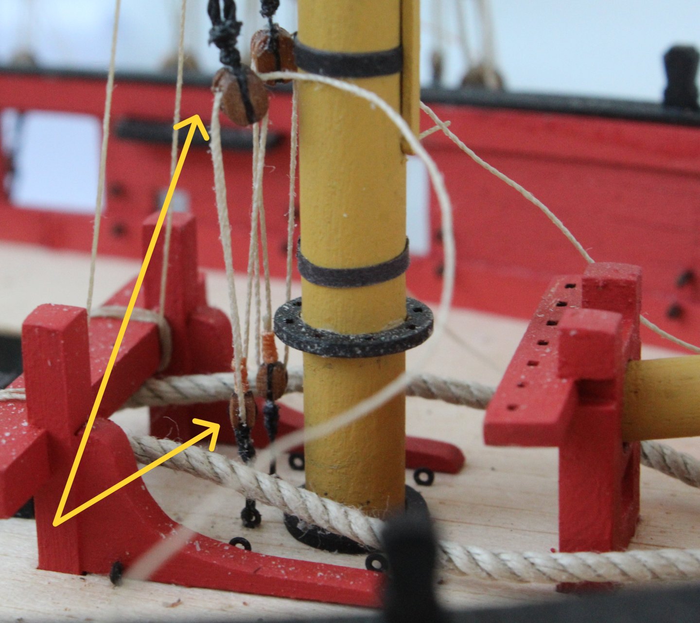
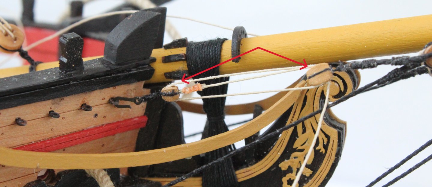
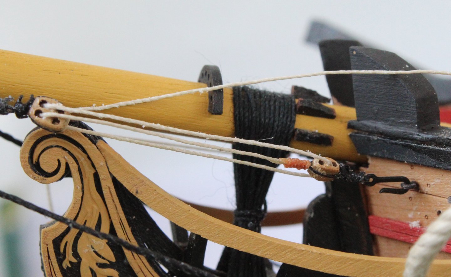
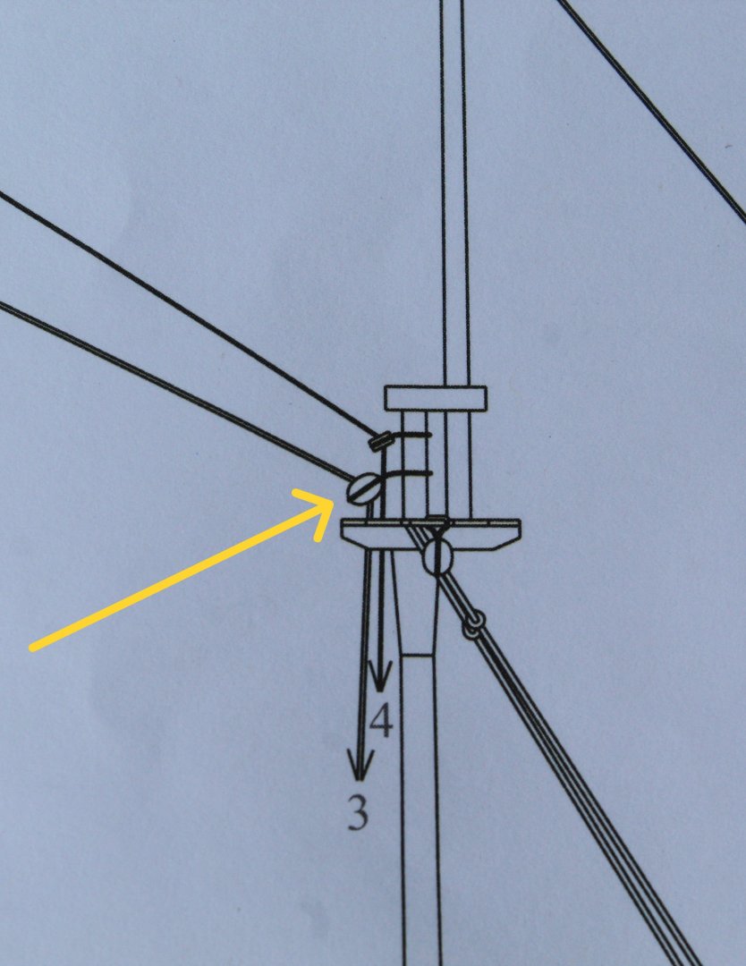
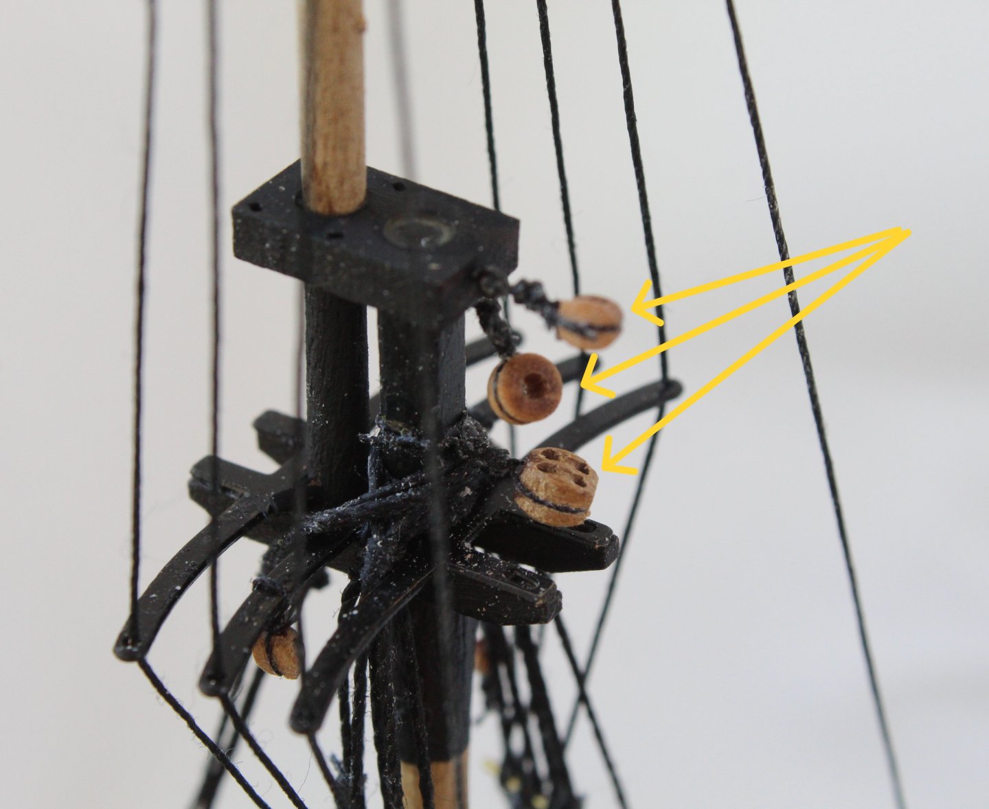
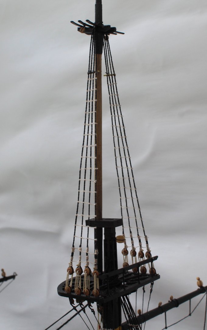
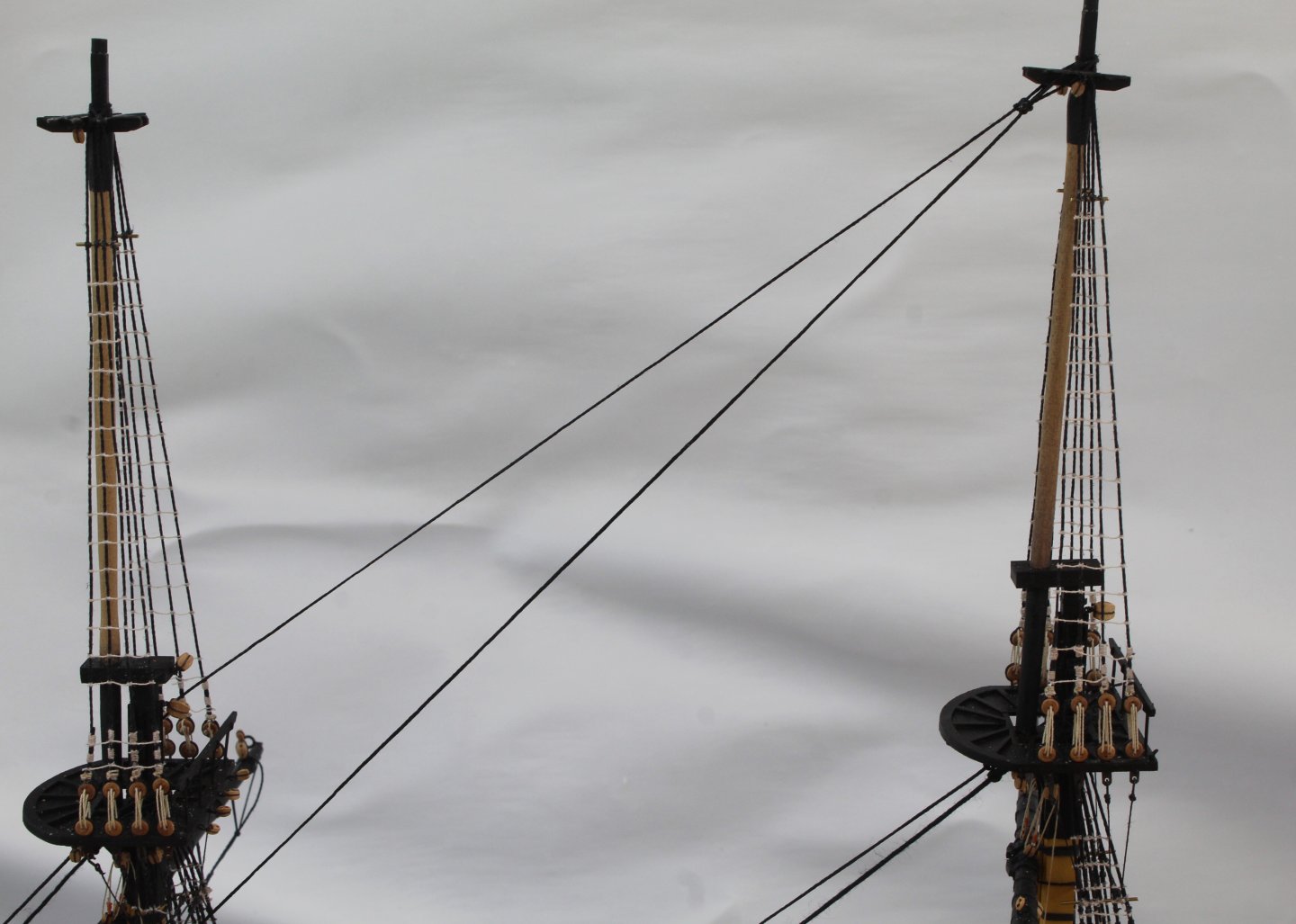
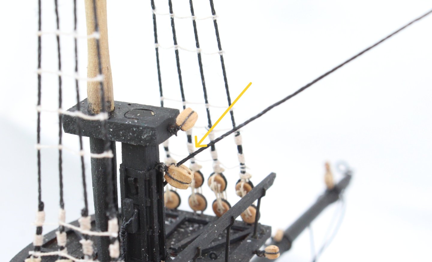
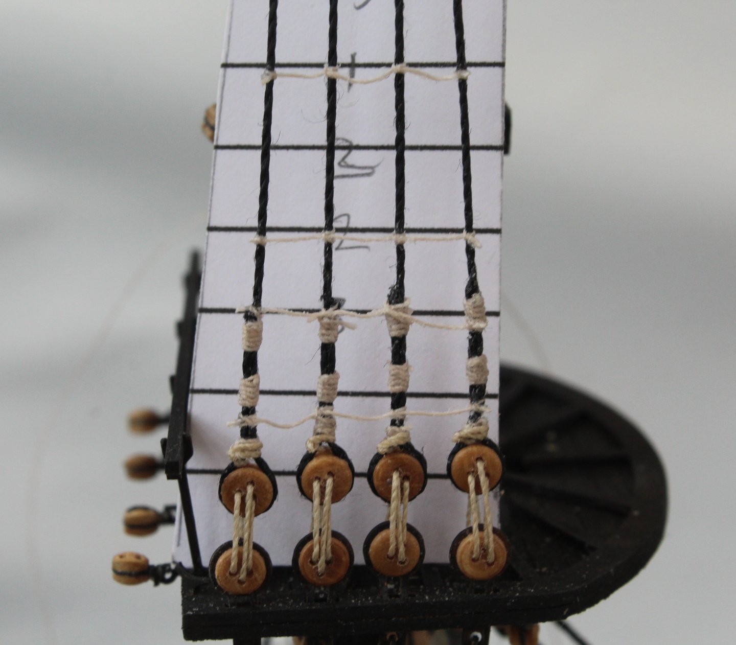
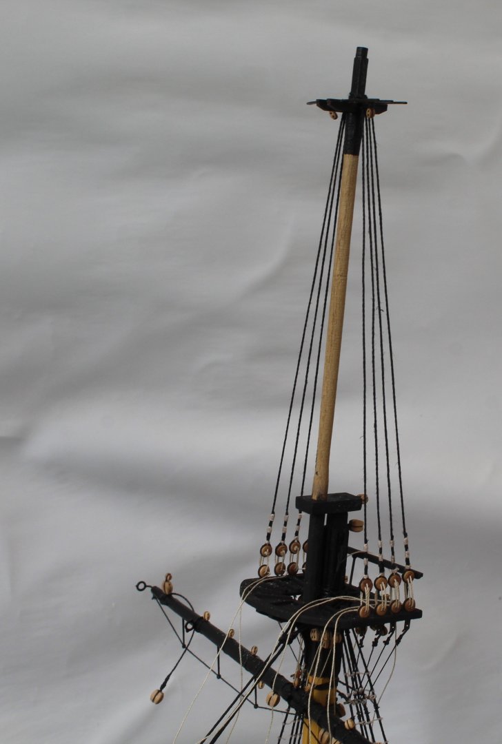
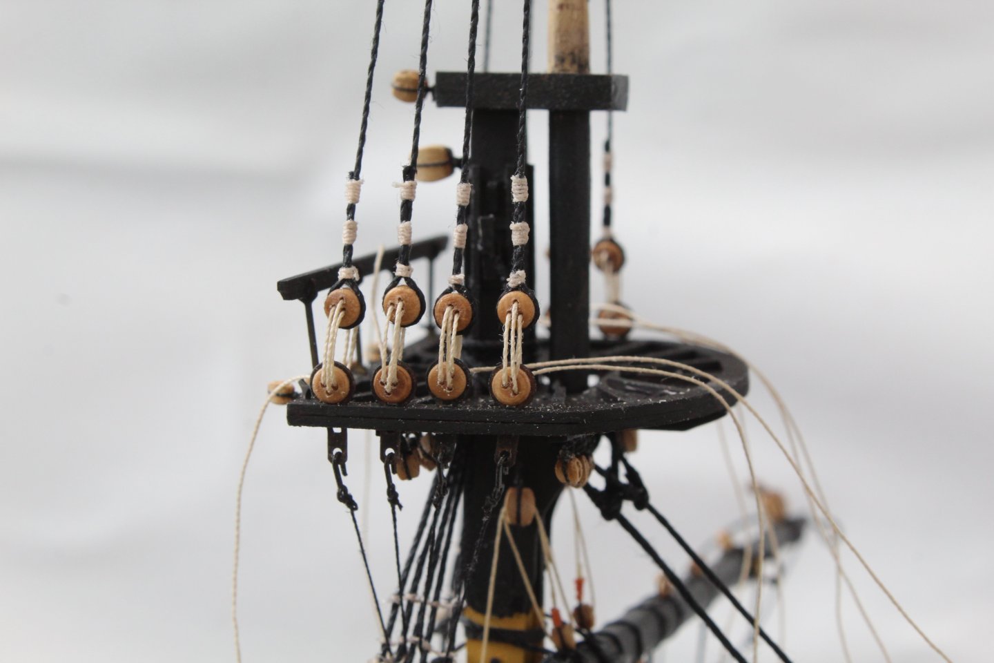
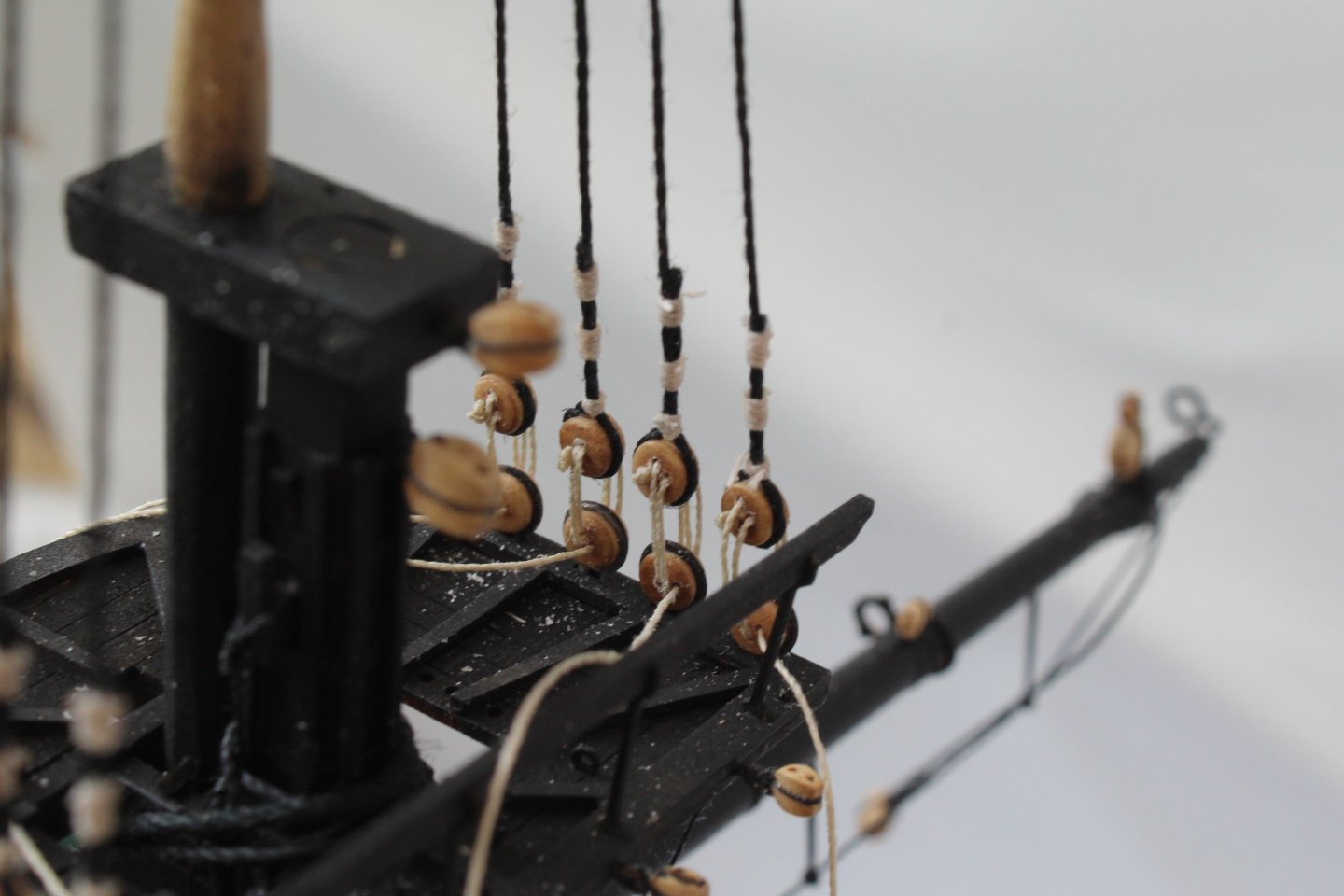
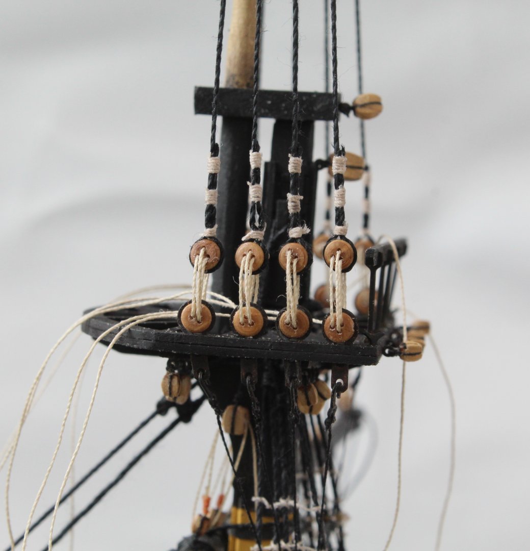
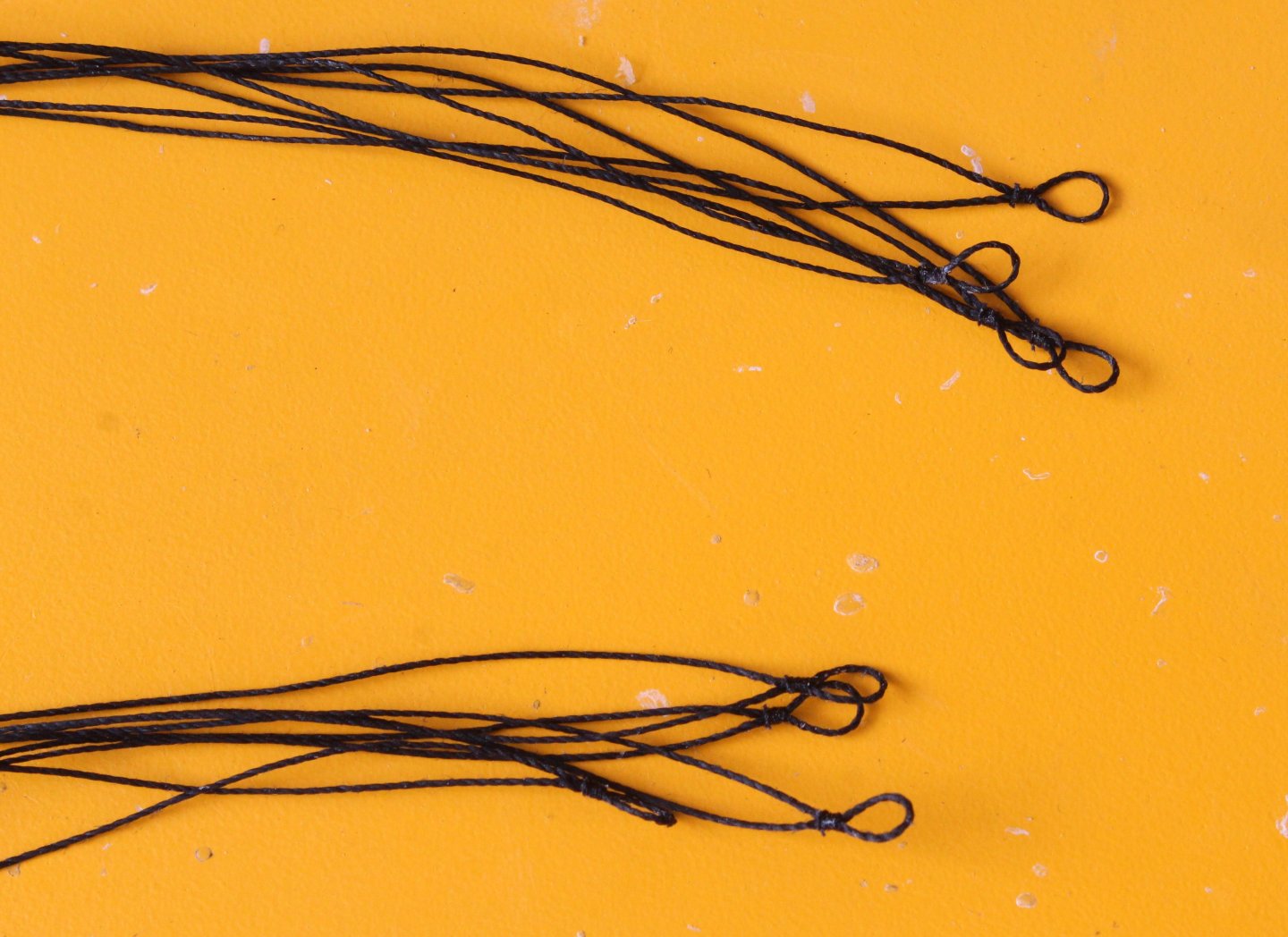
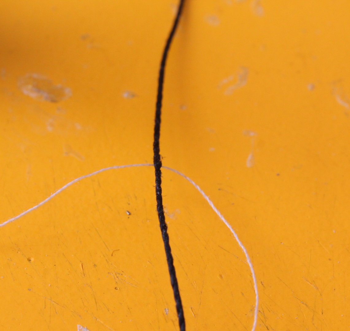
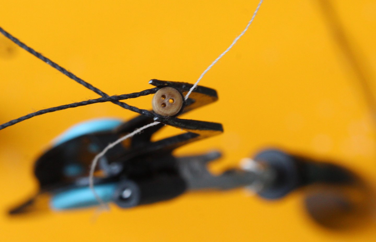
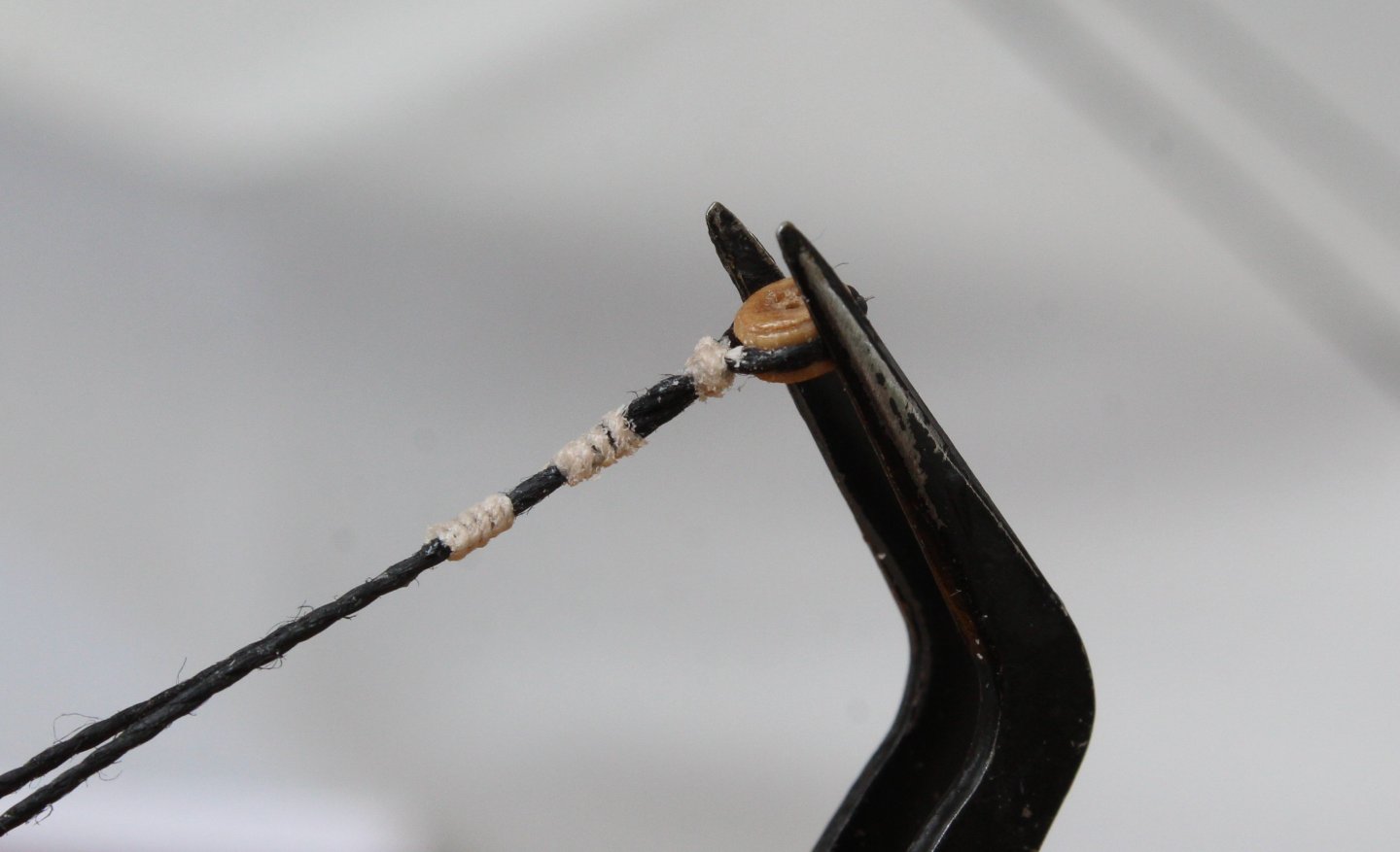
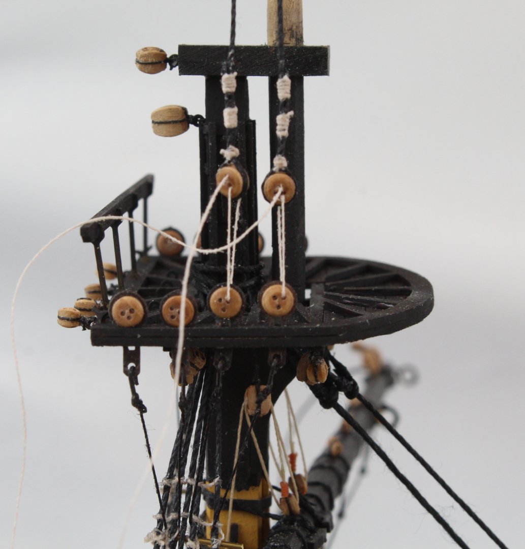
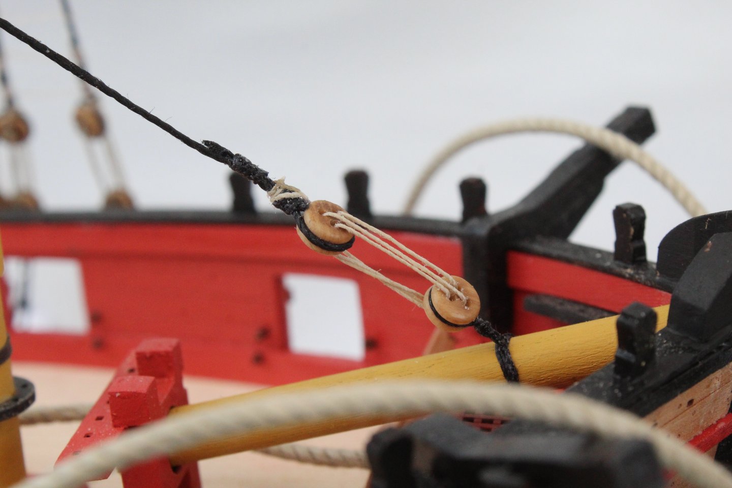
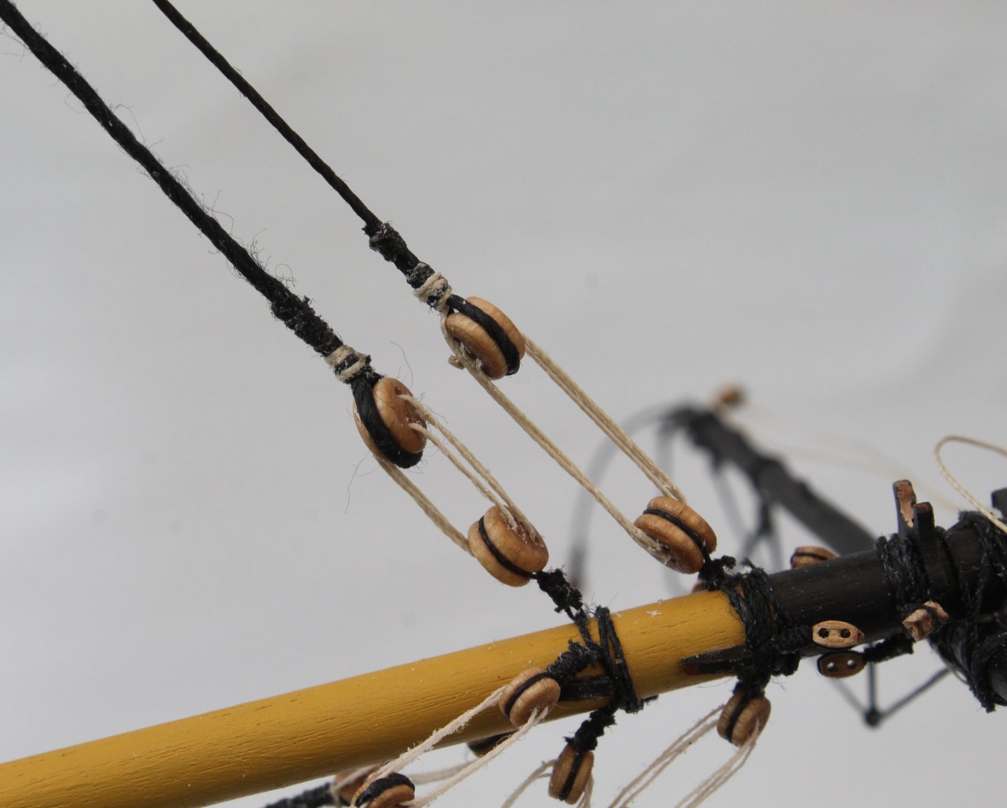
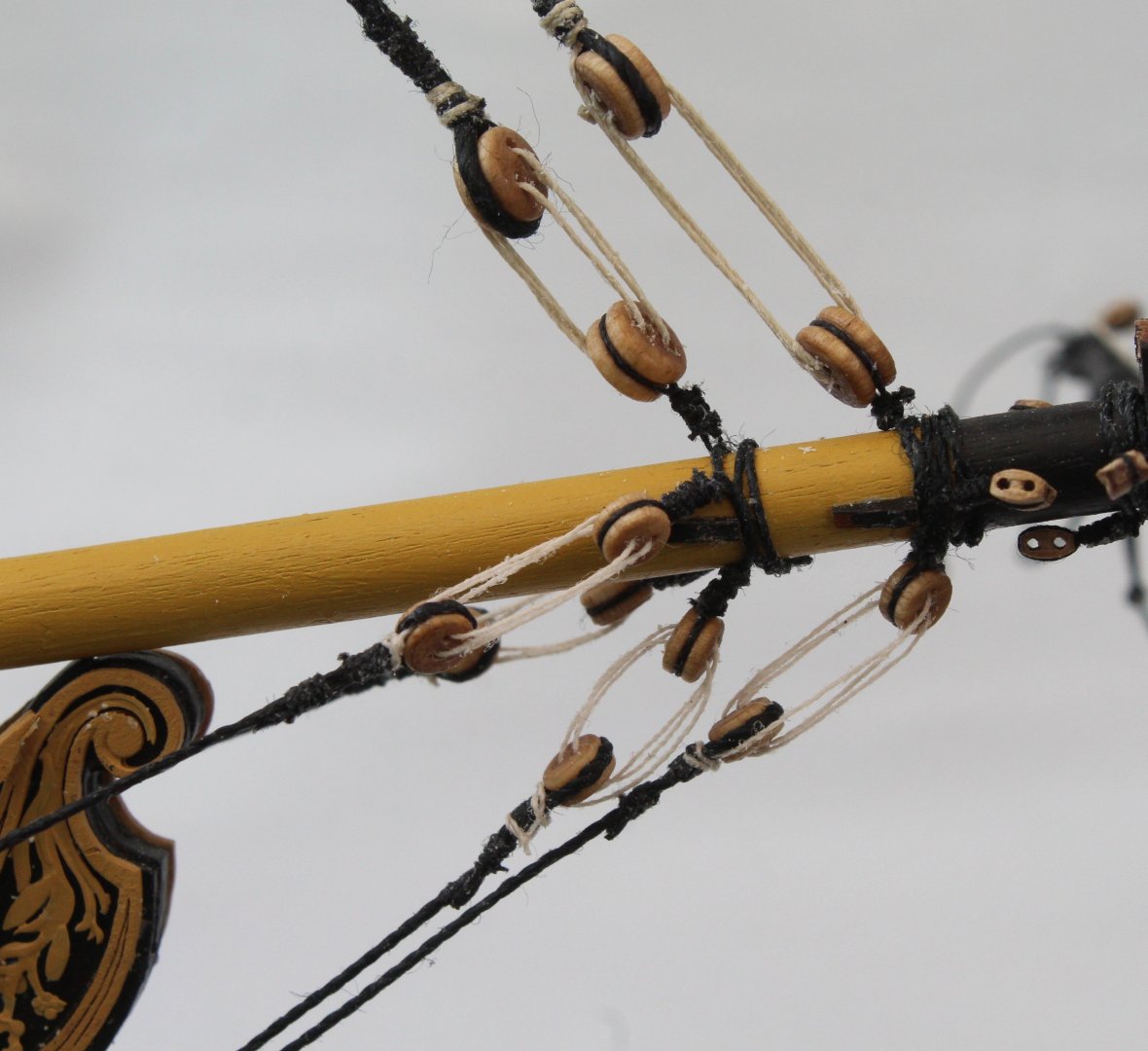
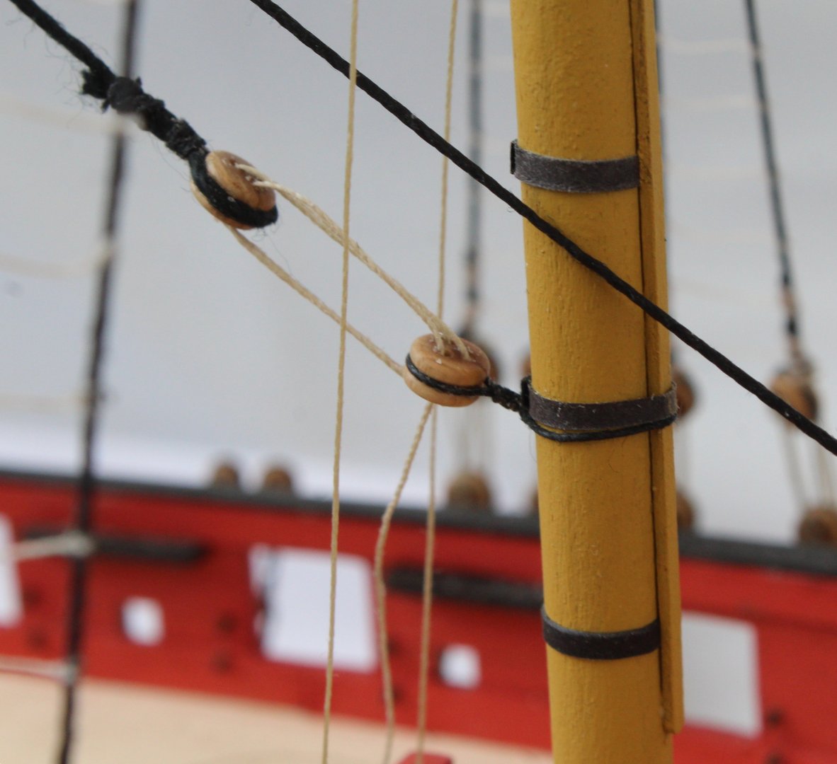
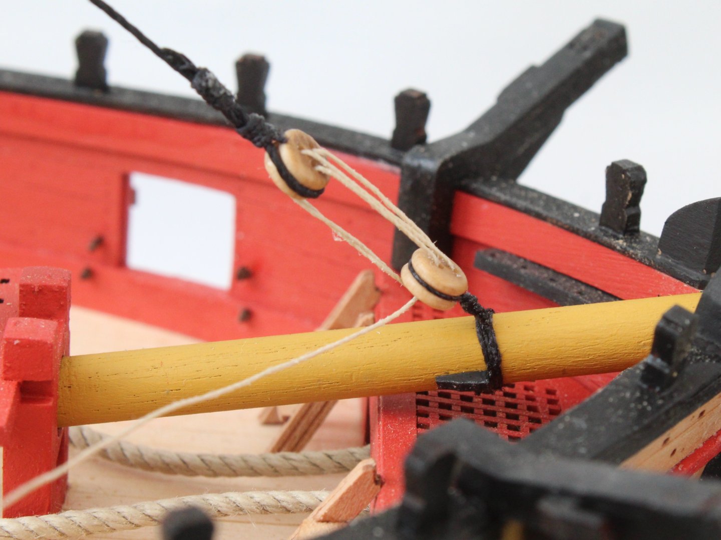
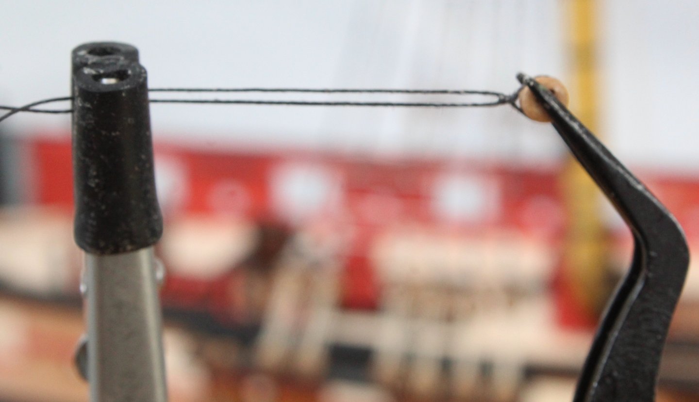
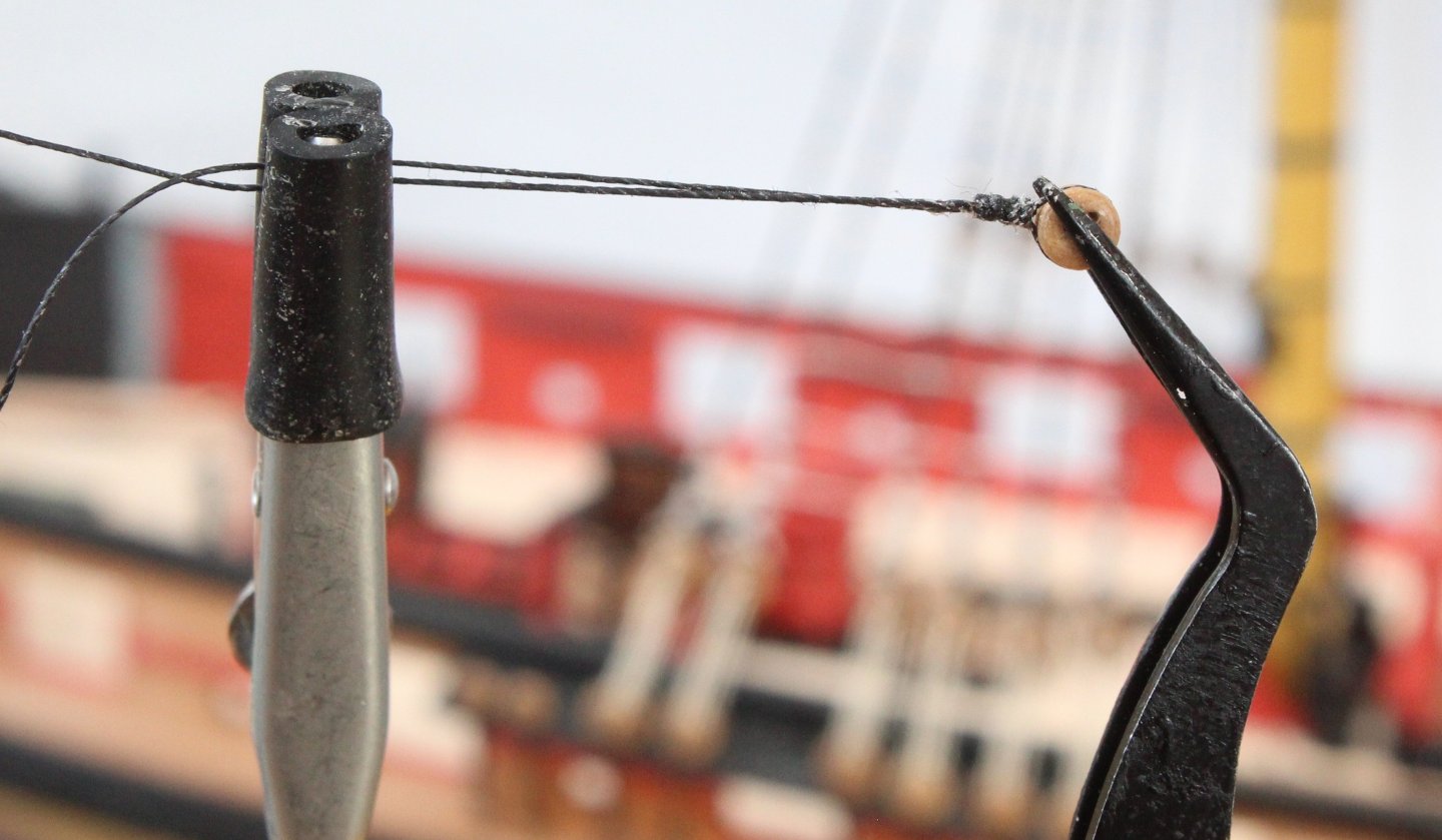
 This post details the method I have used to rig the topsail sail tyes. As can be seen in the first two photos below the rigging is fed through a double block on the topsail yard and is the reeved through a single block located on the topsail platform. The rigging is then belayed to the deck via two 5mm single blocks. Starting with the upper 5mm single block the tye thread is held in place as the block seizing is added as shown by the red arrow in the photo below. The lower thread is then added, held in place with a reef knot. The lower thread is then held in the quad hands so the seizing can be added, The block is then reversed so the seizing can be added to the upper tye thread. The completed upper 5mm block is shown in the next photo. These threads are then reeved through the 3mm single block and the 4mm double block, the 4mm block is shown in the photo below. A length of thread is then seized around the lower 5mm single block. An eyebolt is then added to the thread, using a template to set the distance between the eyebolt and single block. The next set of photos shows the completed rigging.
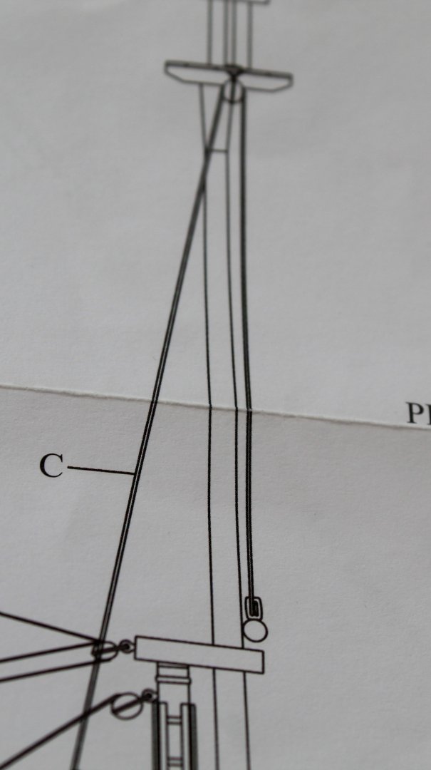


- 241 replies
-
- 8
-

-
- Vanguarrd Models
- Harpy
- (and 1 more)
-
Well done on completing a fantastic looking model, one you can be really proud of. 👏👏👏
- 332 replies
-
- 2
-
-

-
- Harpy
- Vanguard Models
- (and 1 more)
-
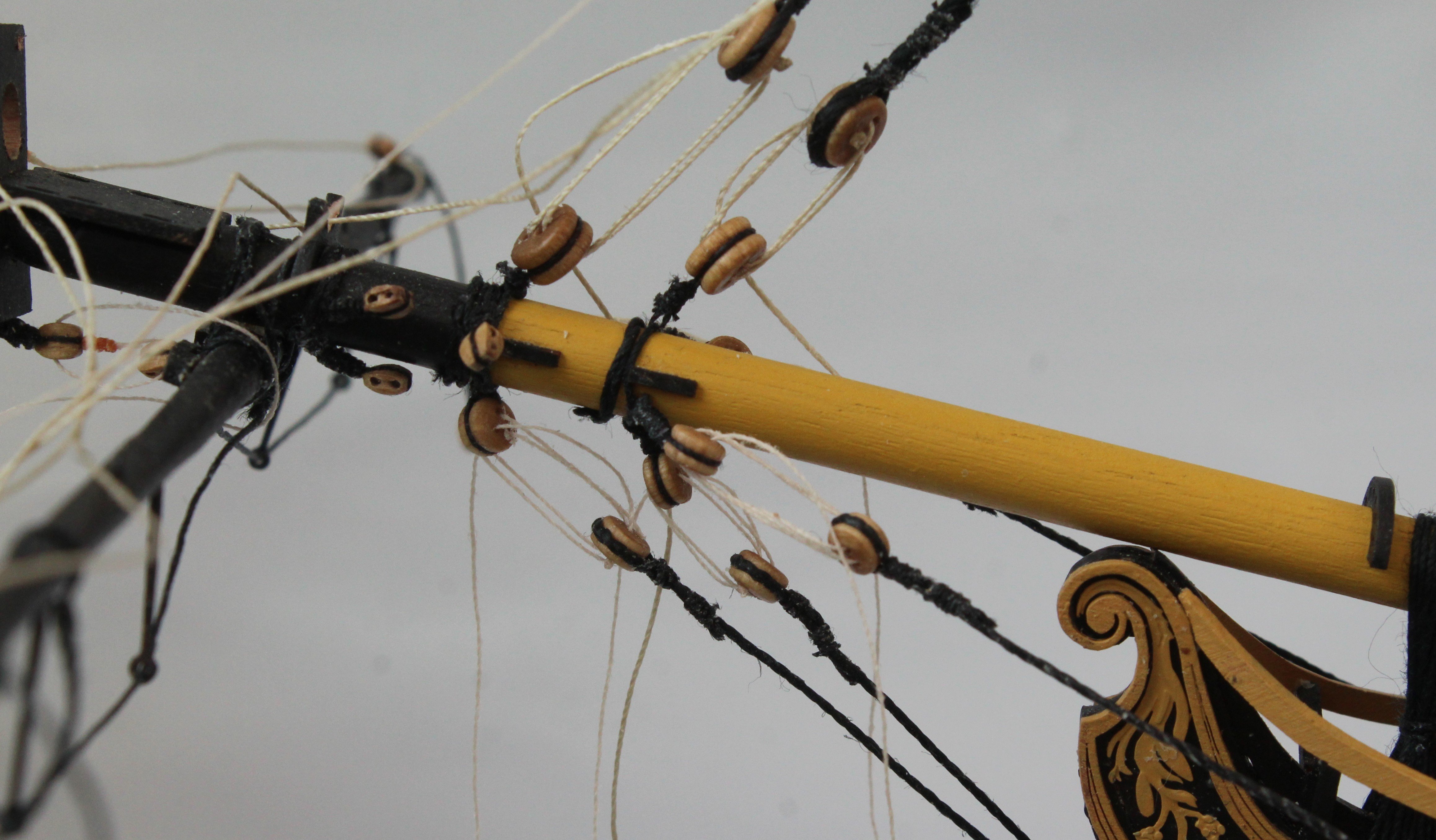
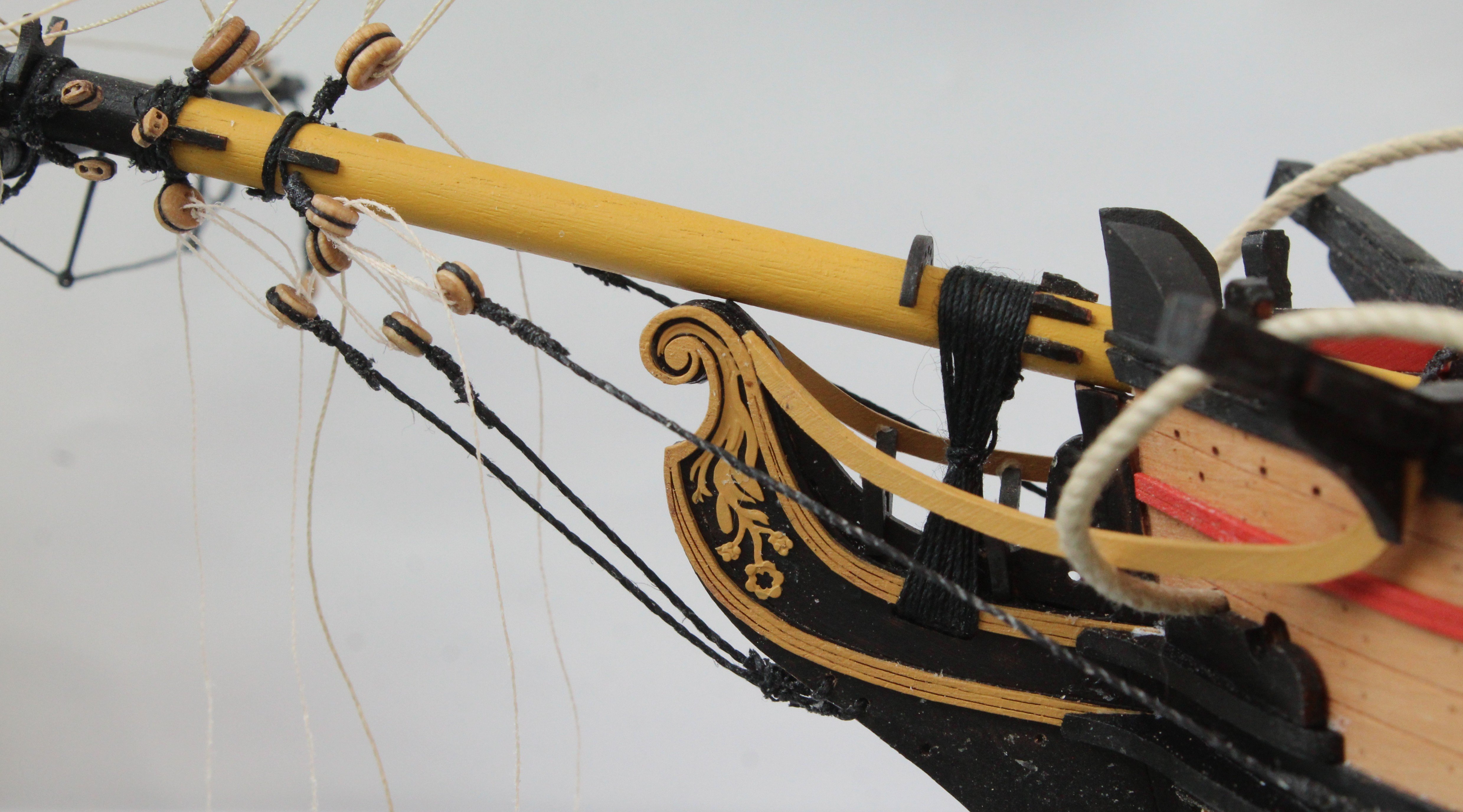
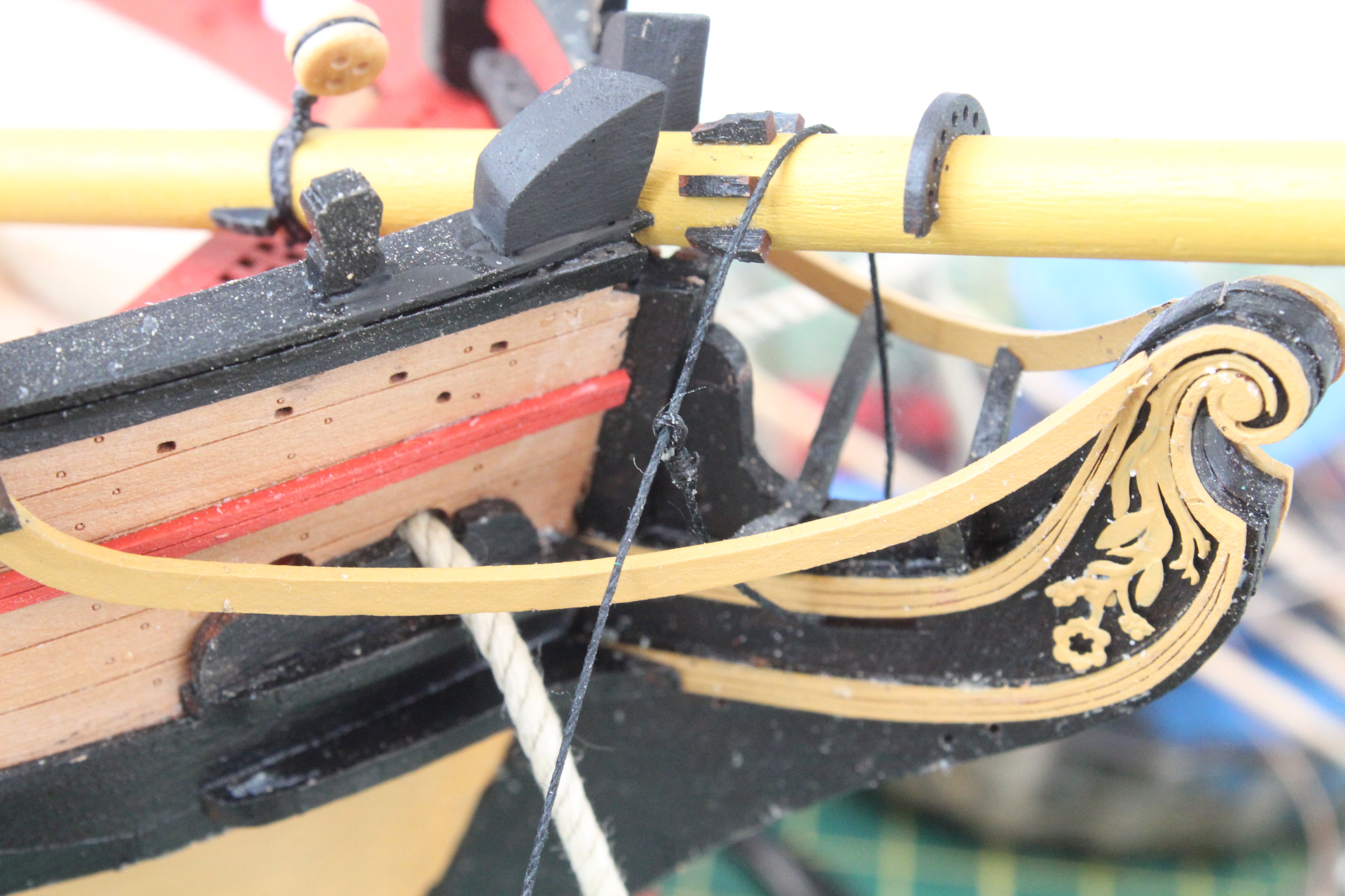
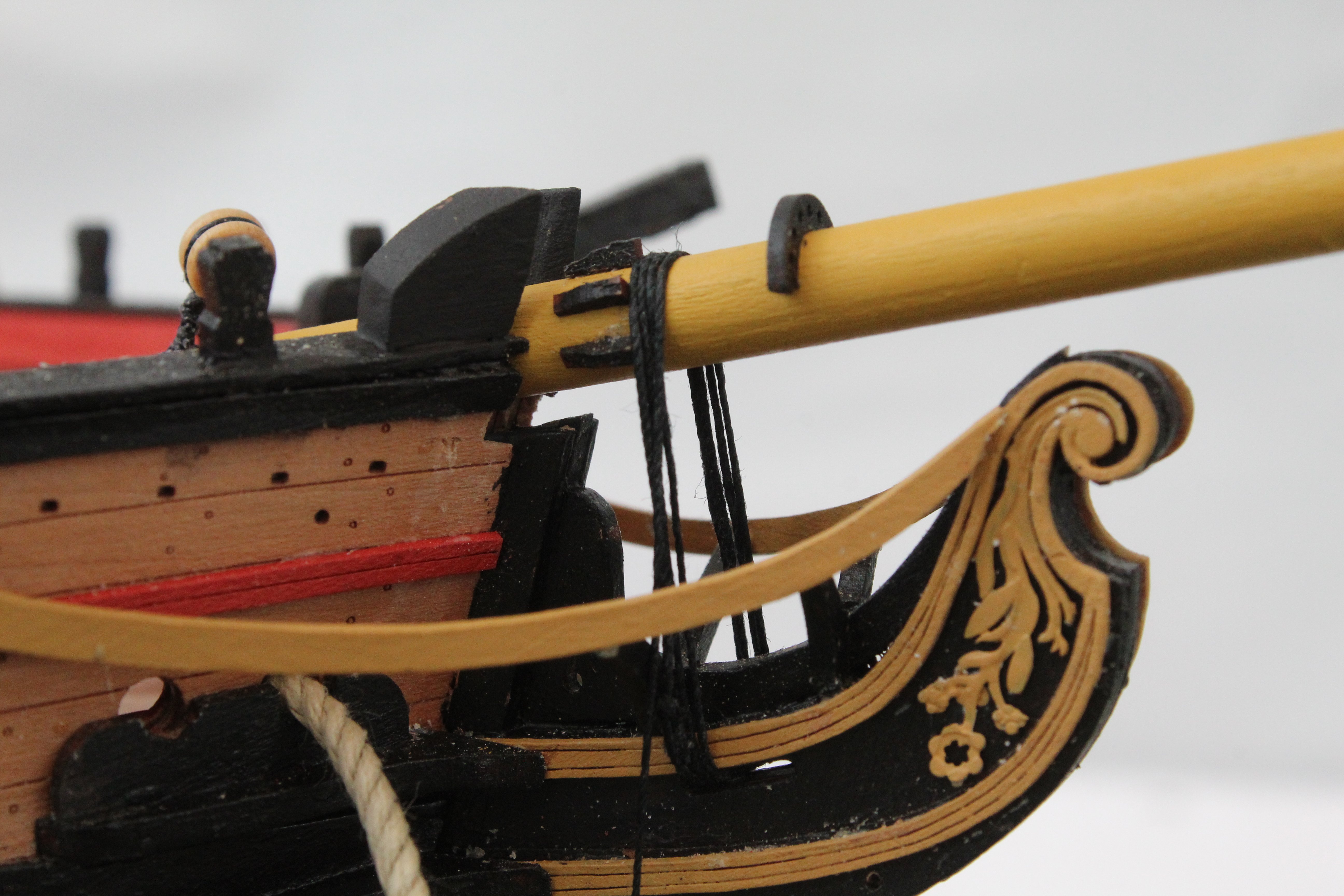
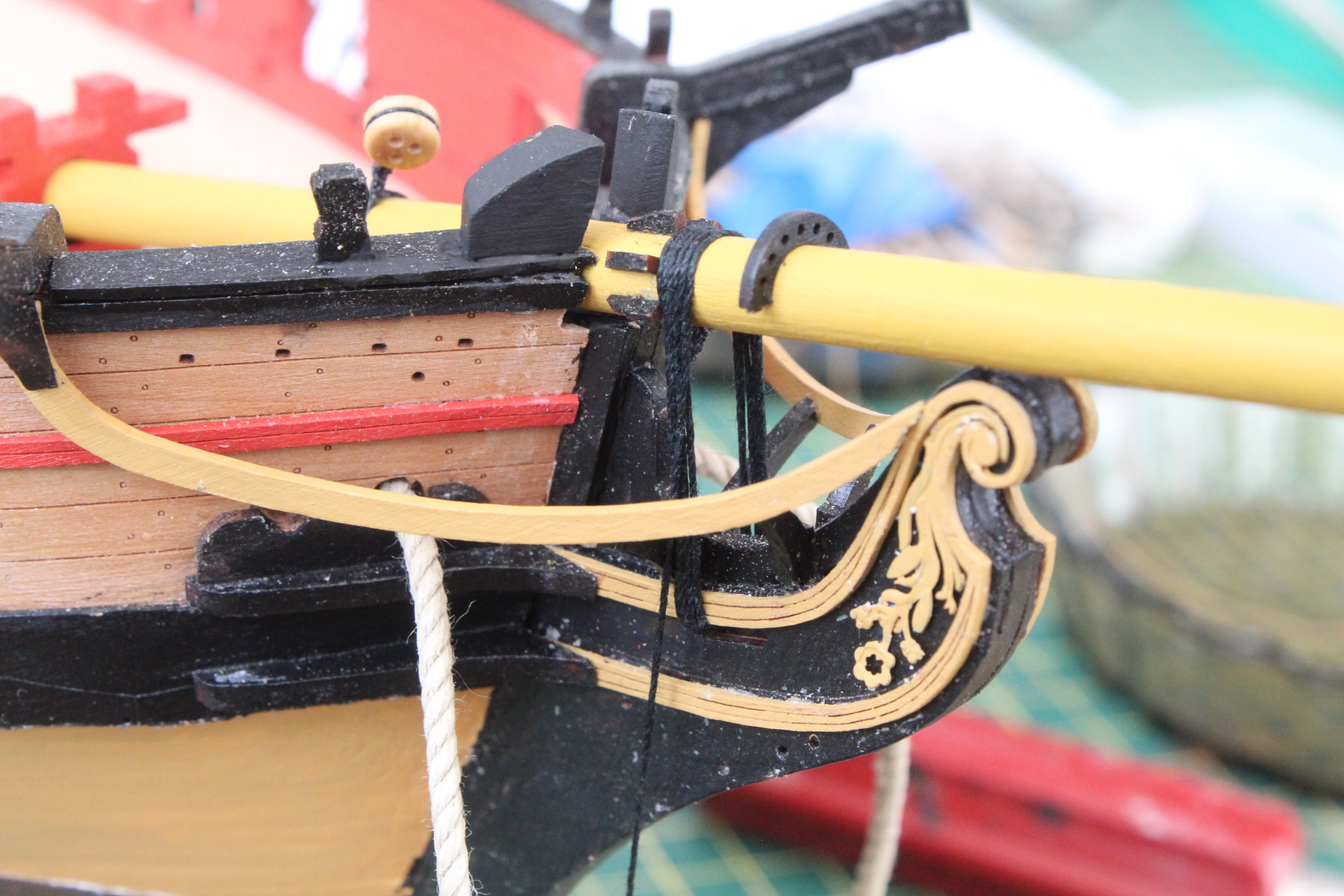
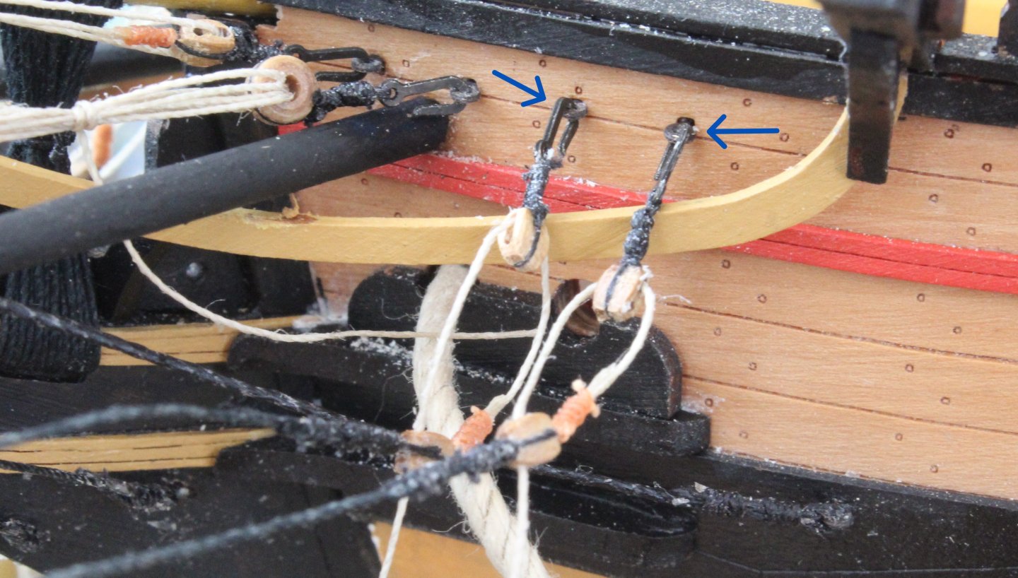
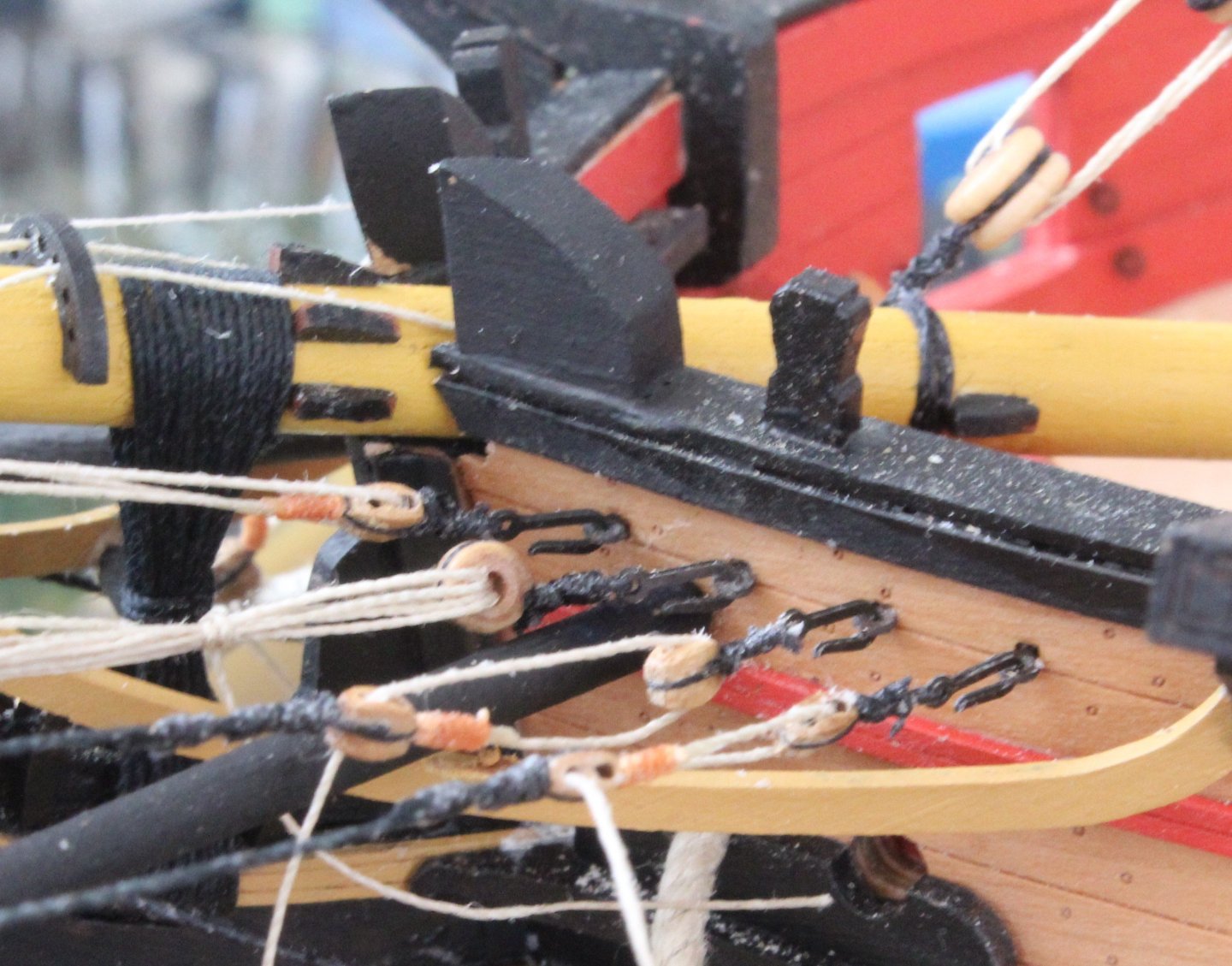
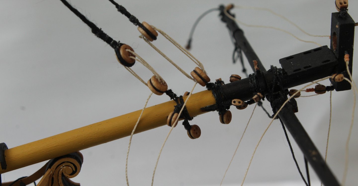
I spent a bit of time yesterday belying the rigging that had been run in, some of which can be seen in the first three first photos below. With the jibboom and flying jibboom added their respective shroud rigging were next to be added. I opted to use hooks to secure these blocks to the bow for ease of installation, as can be seen in the two photo below, noting the plan sheet shows these blocks should be seized directly to the eyebolts. The free ends of the inter-block rigging will be belayed to pins located on the bow inner bulwark belay pin racks. The shrouds are also feed through eyelets located on the spritsail yard before being secured to the ends of the jibboom and flying jibboom.

- 241 replies
-
- 9
-
-
- Vanguarrd Models
- Harpy
- (and 1 more)
-
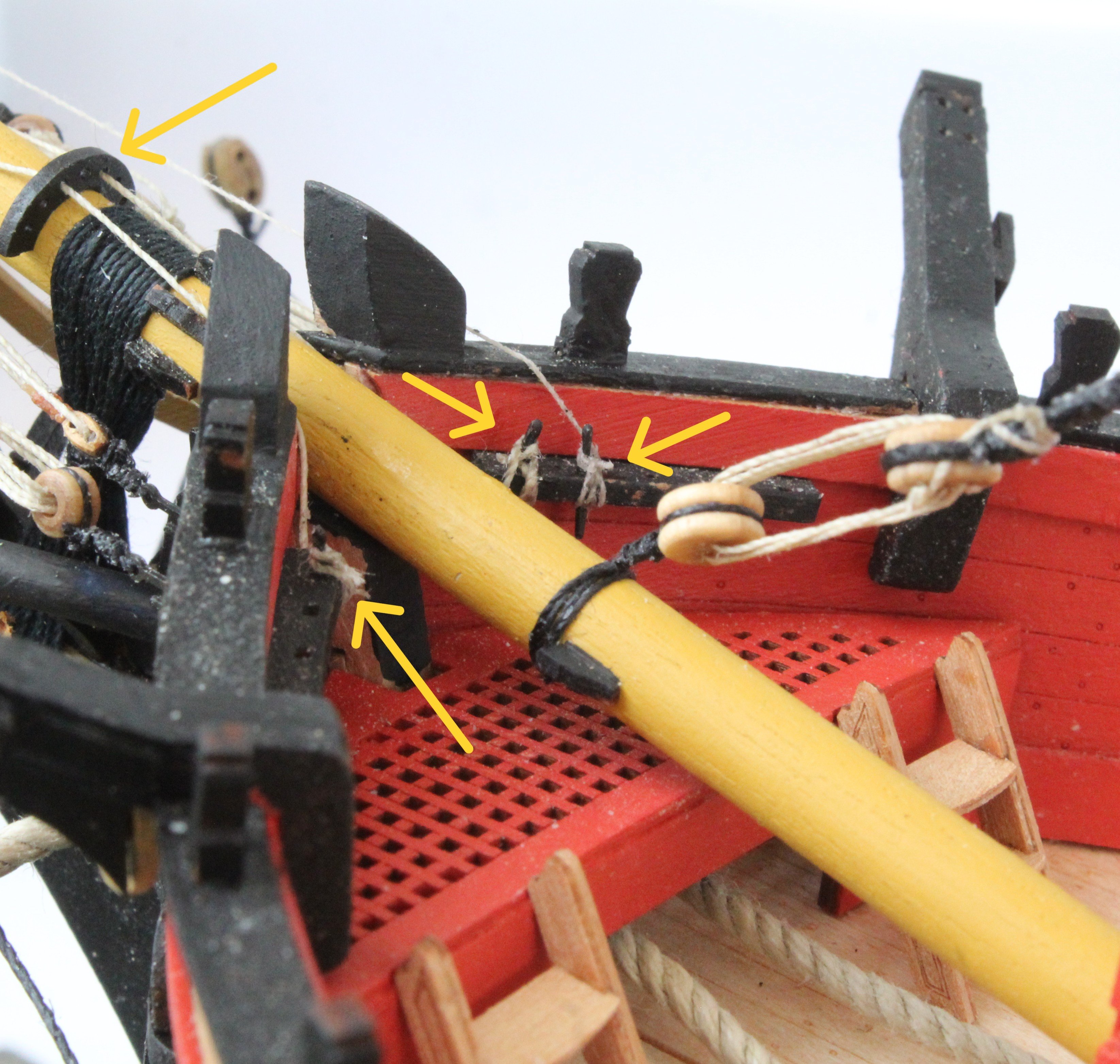
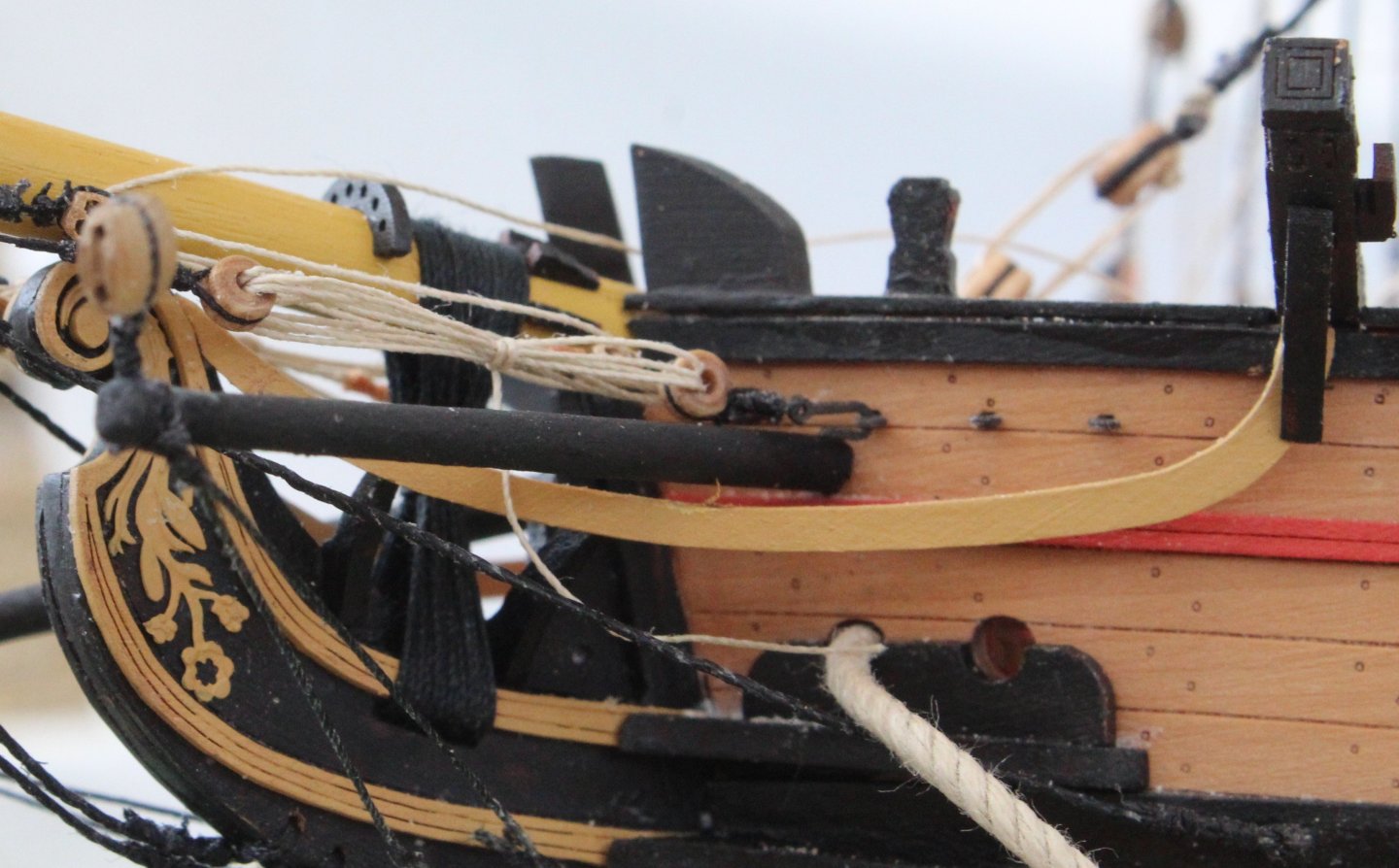
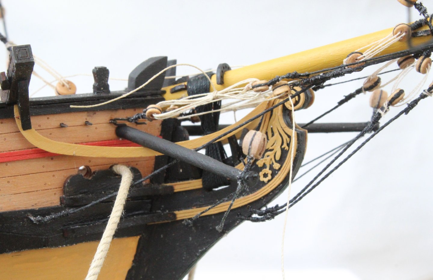
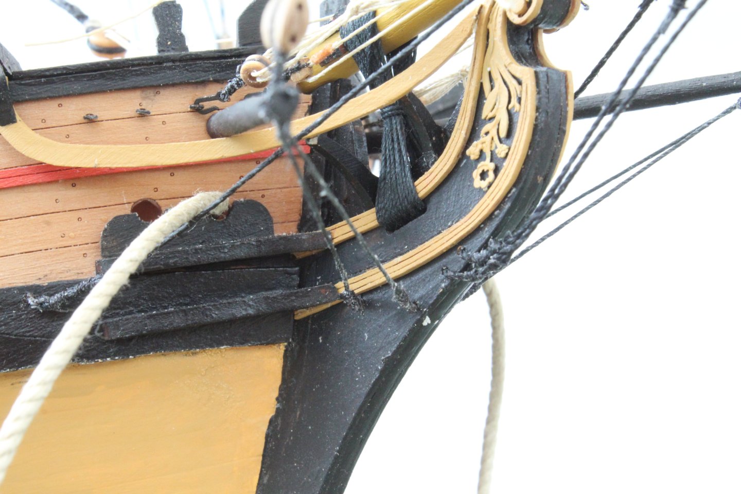
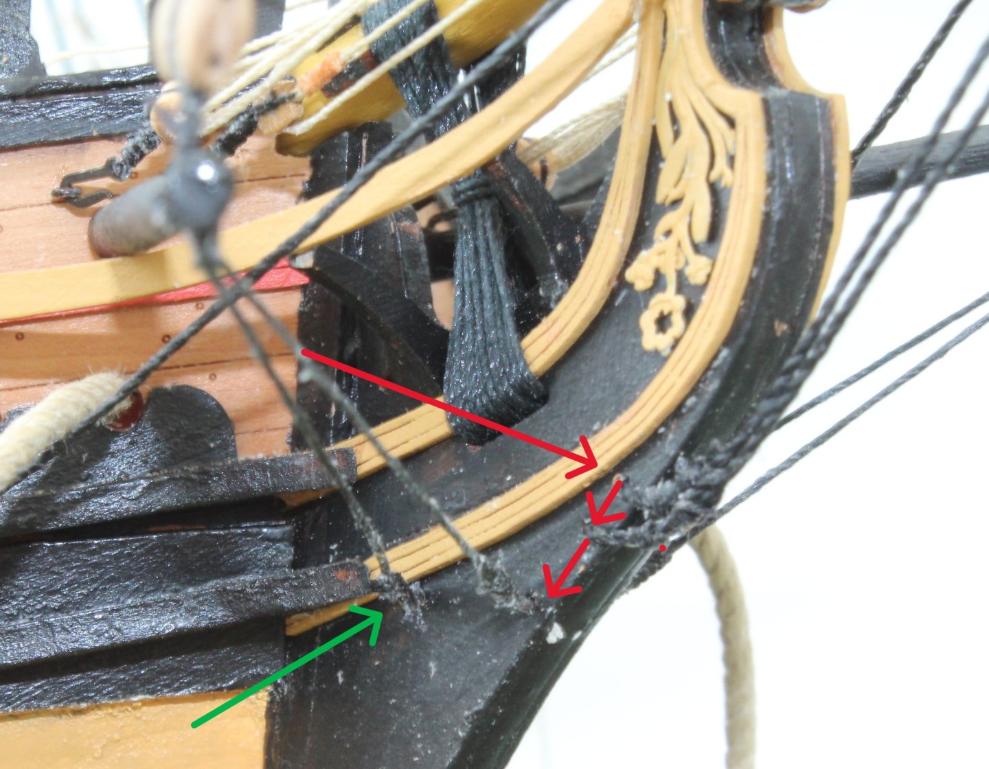
The two boomkins have now been added. It was a simple task to cut and shape two lengths of 3mm dowel as per the plan sheet. Once painted they were glued in place. The shroud were added along with the 5mm single blocks. The boomkin shrouds were added, as shown below. Can you spot the error I made? The next photo shows the error. The green arrow shows what I did right. The three red arrows shows where the various shrouds should have been placed. Thankfully, as far as I am concerned, it does not matter as no one will notice this once the model has been completed.

- 241 replies
-
- 8
-
-
- Vanguarrd Models
- Harpy
- (and 1 more)
-
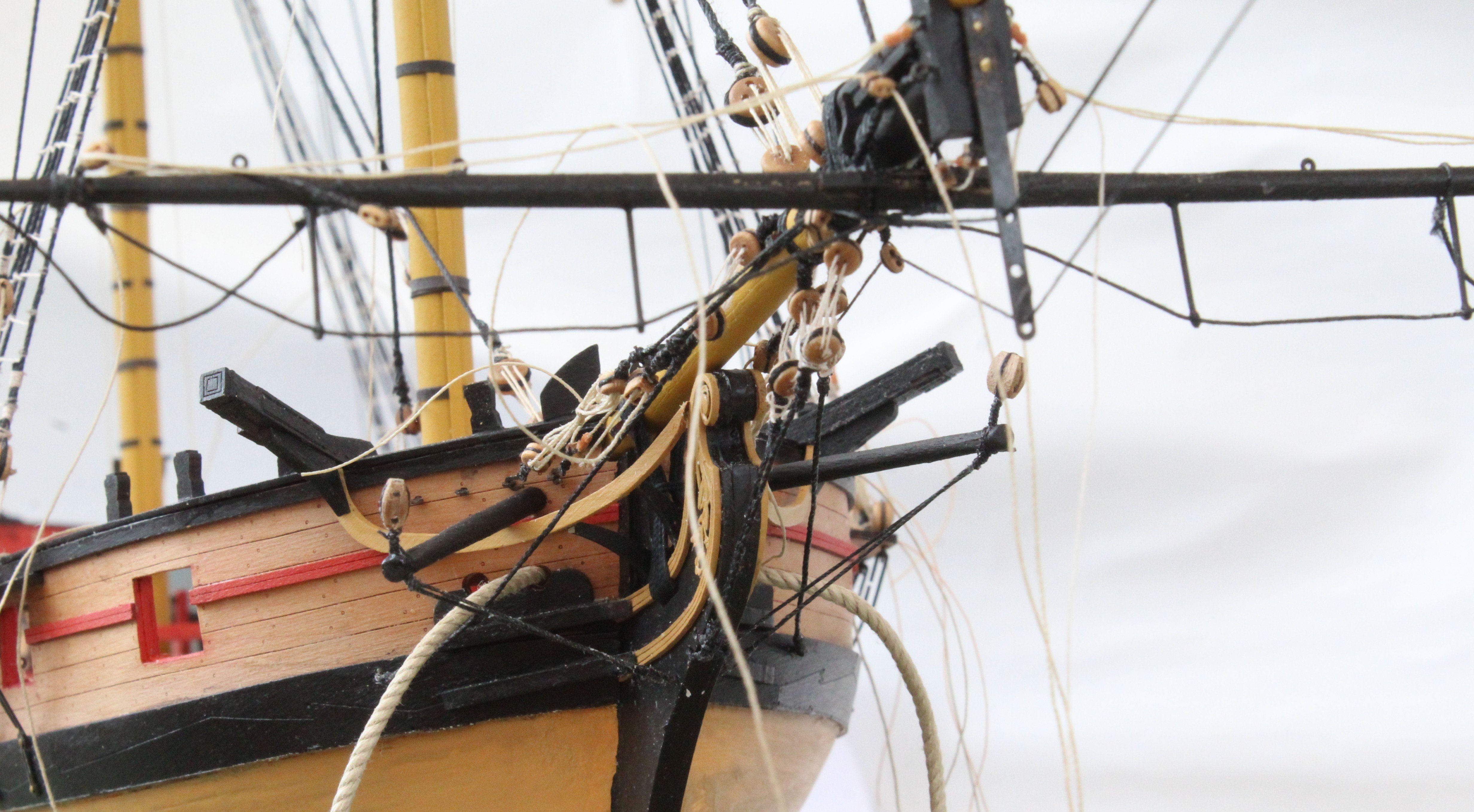
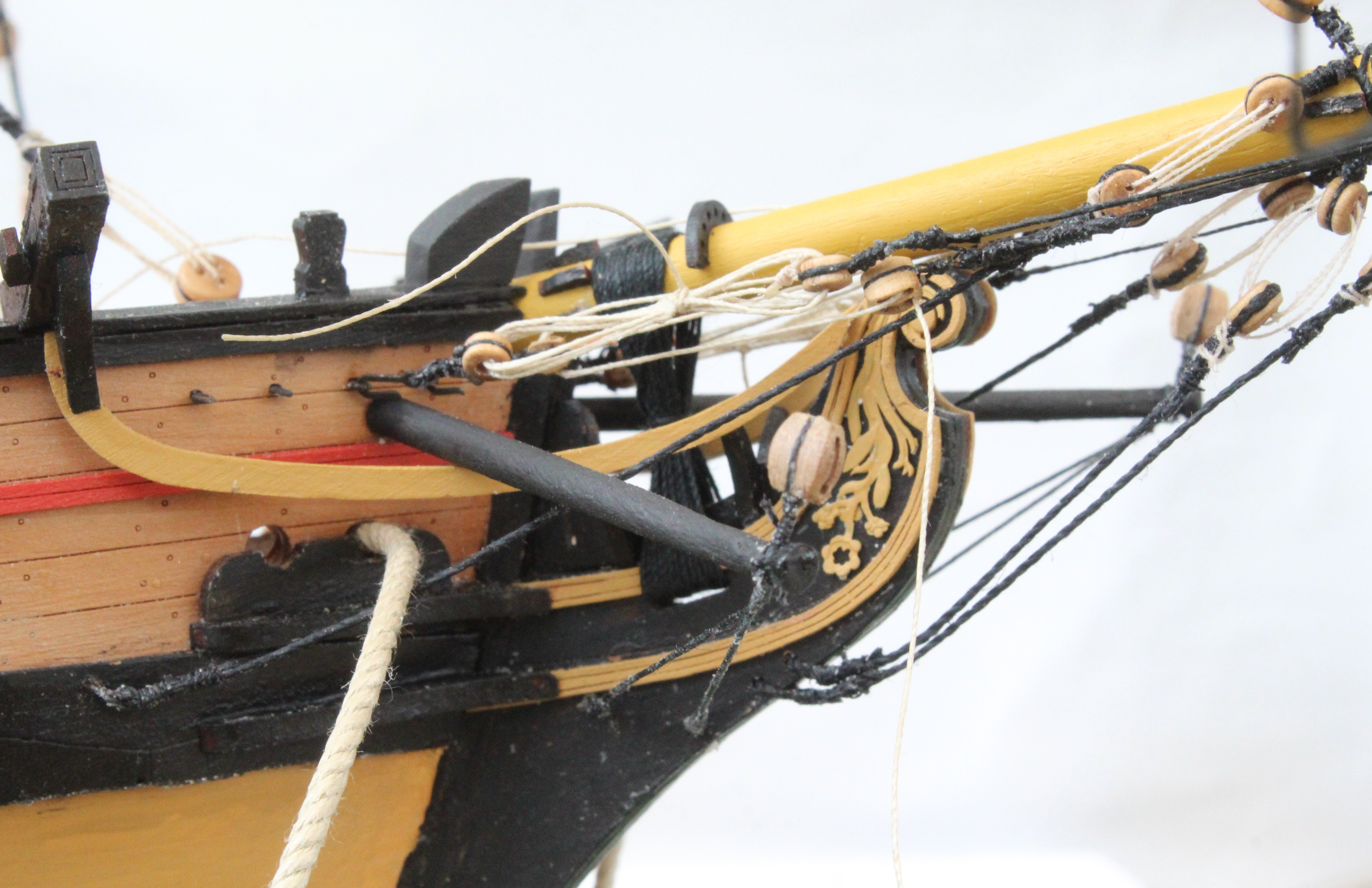
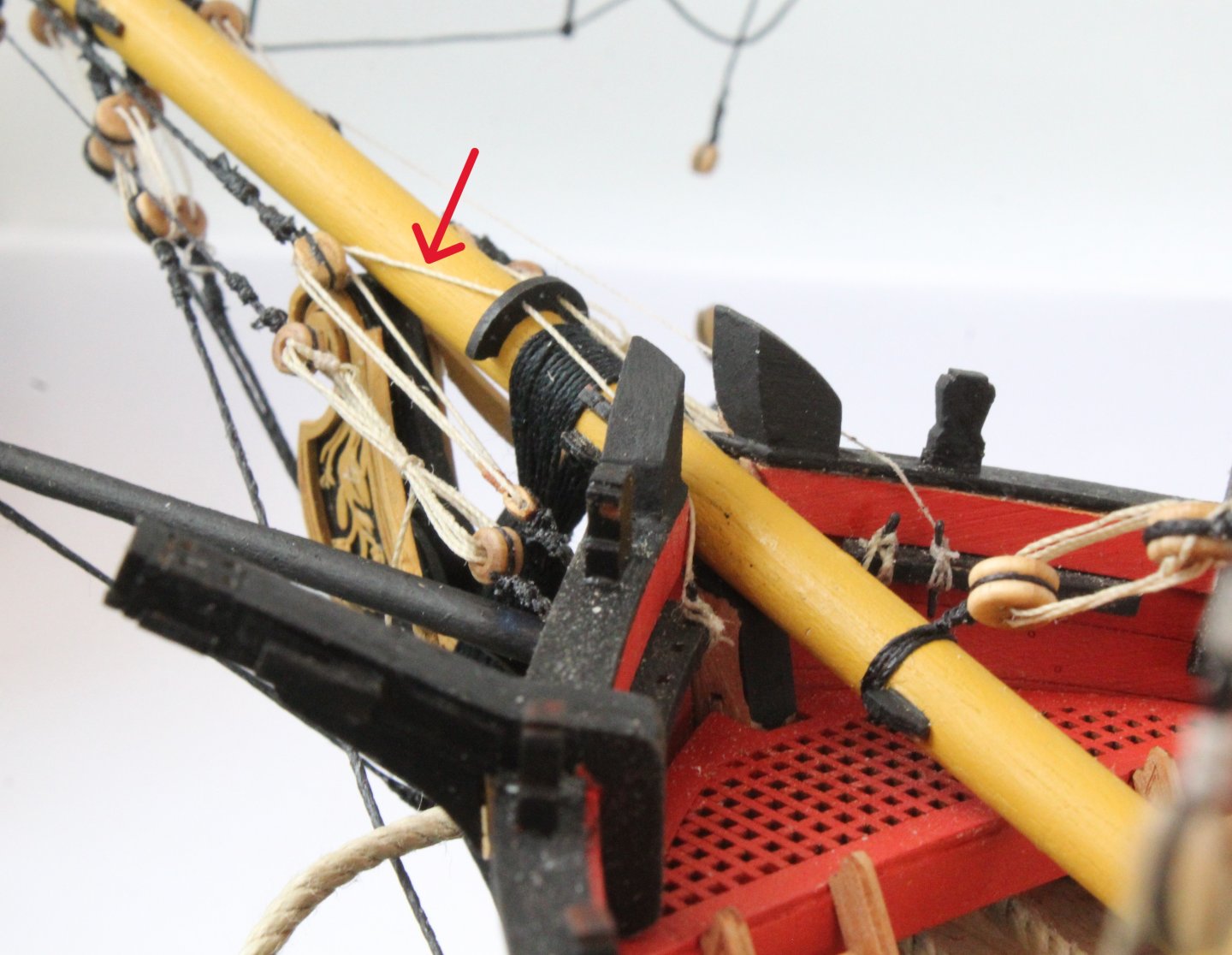
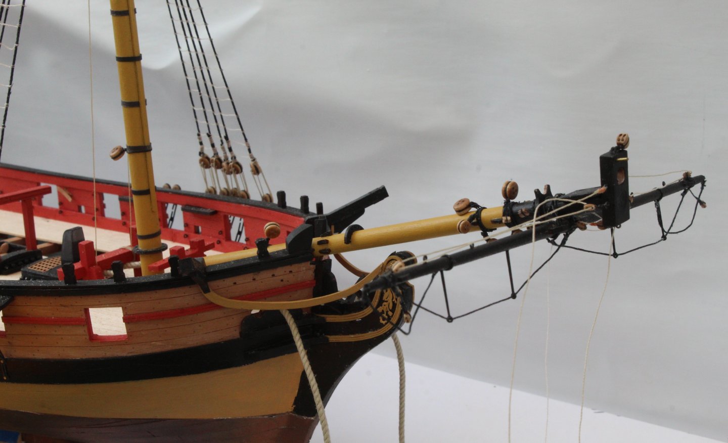
Before moving on to making and adding the boomkins I decided I should add both the jibboom and flying jibboom so the fore topsail and fore topgallant stays could be rigged. The first two photos show the jibboom and flying jibboom in place. The dolphin striker was also added. As you will note, when looking at the photo, I made an error with where the fore topsail sail stay should be reeved. I used the upper hole rather than the middle hole. I only realised this error after I had added the thimble to the stay end. I concluded that I could accept this mistake rather than running in a new stay. Both stays are belayed using thimbles, with the reciprocal thimbles for each stay hooked to eyebolts on the bow, as can be seen in the next photo. The next photo shows the foremast with the all the various mast stays in place. The final photo of this post shows the current status of the Harpy rigging.


- 241 replies
-
- 9
-
-
- Vanguarrd Models
- Harpy
- (and 1 more)
-
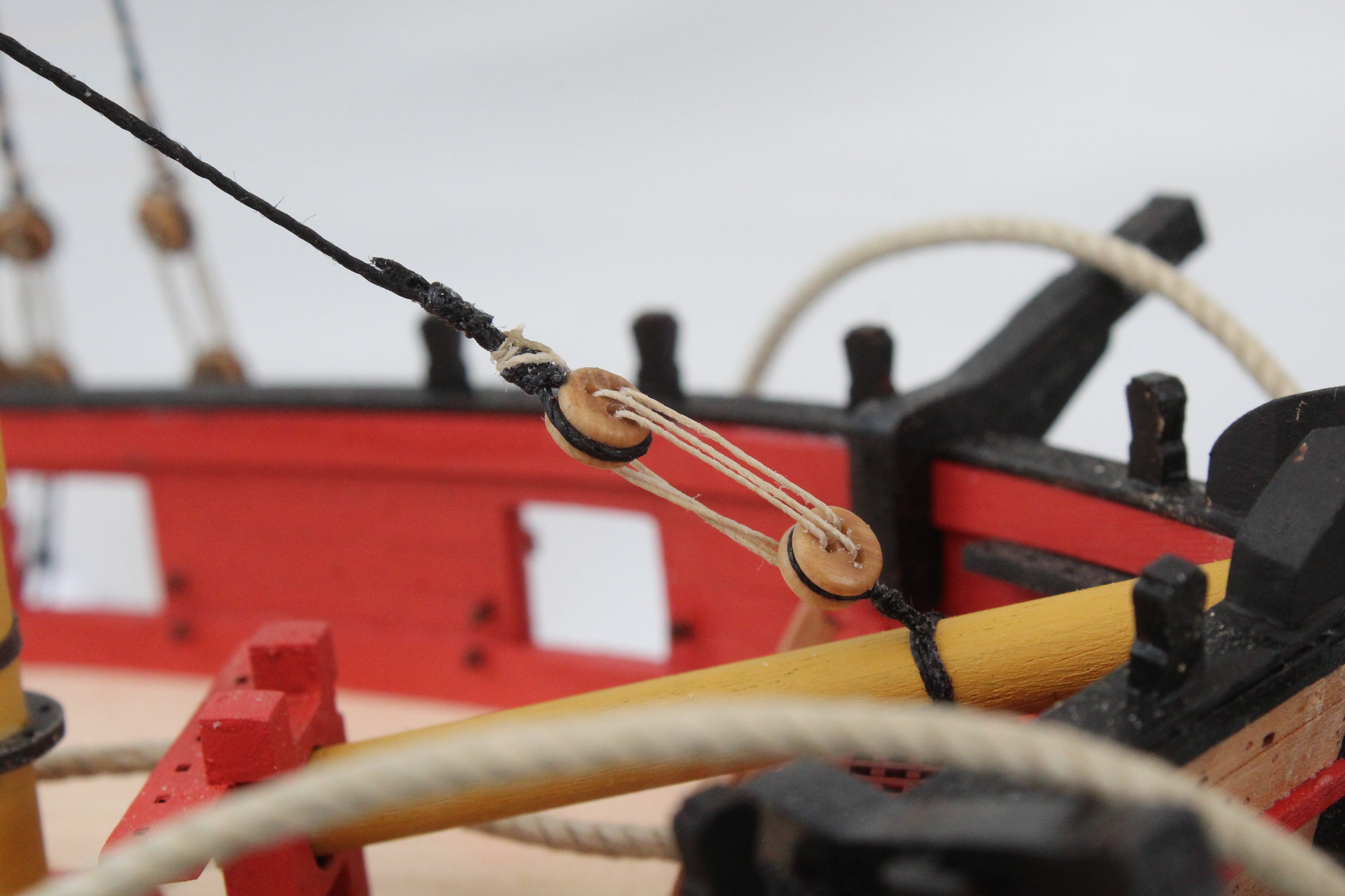
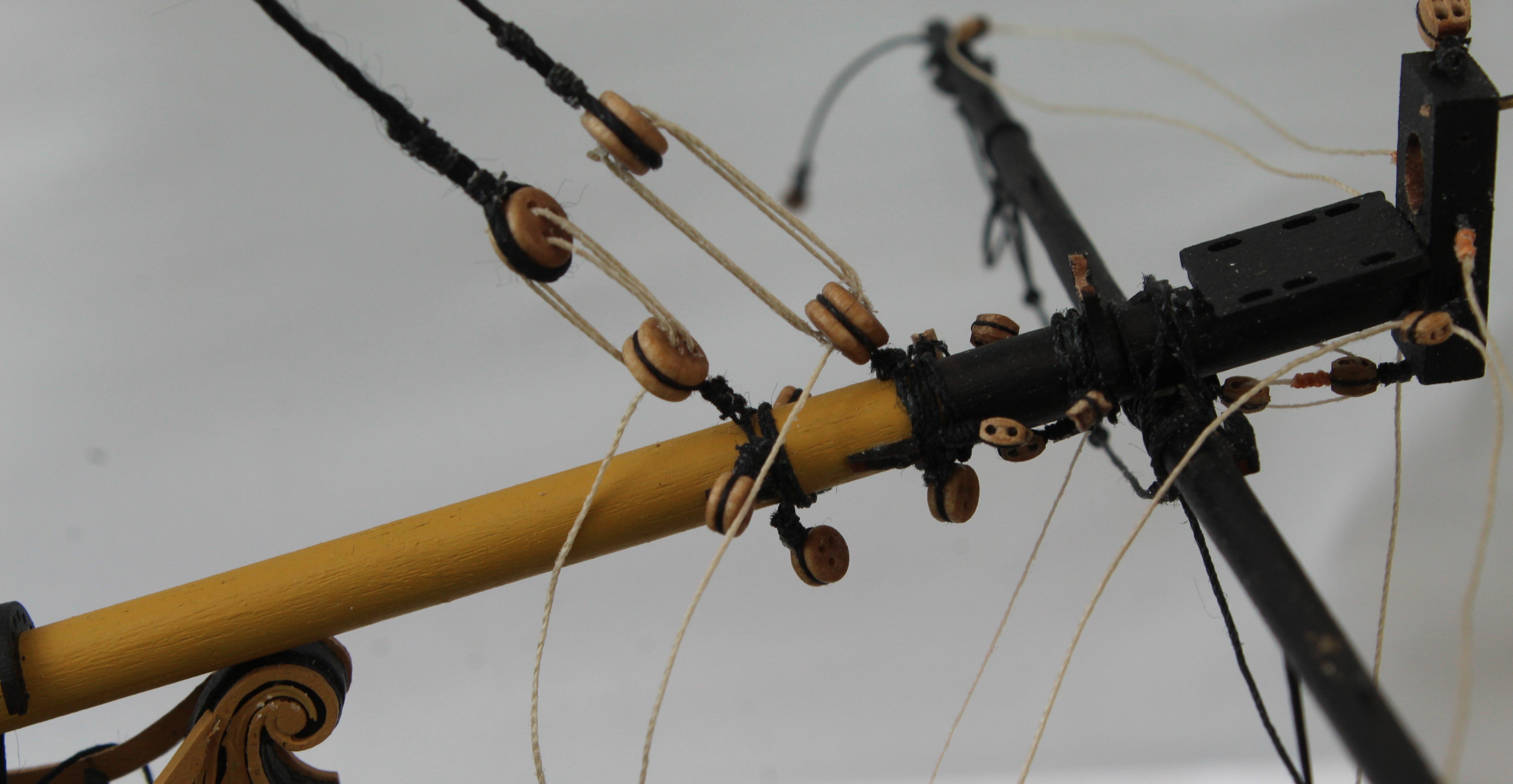
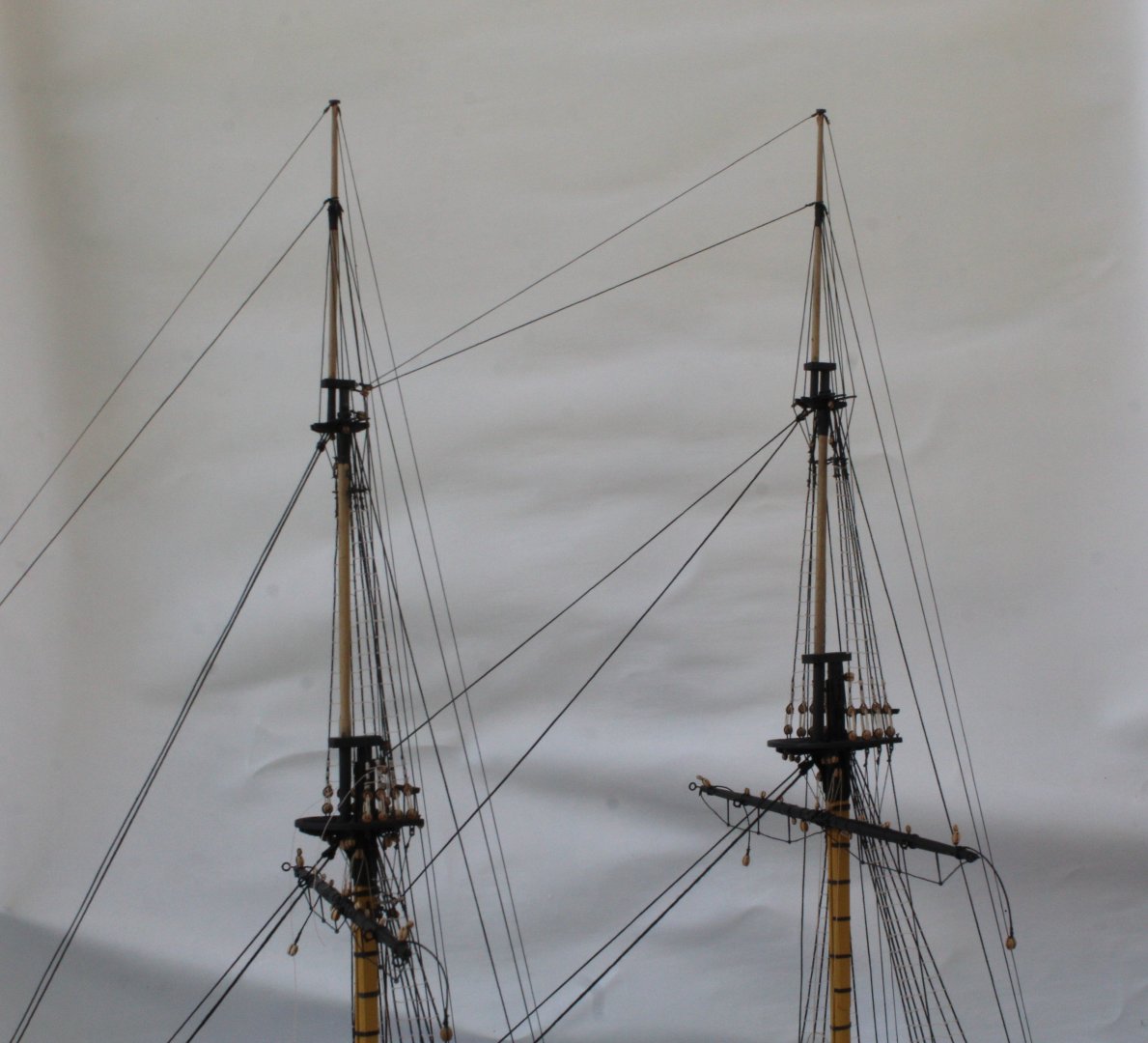
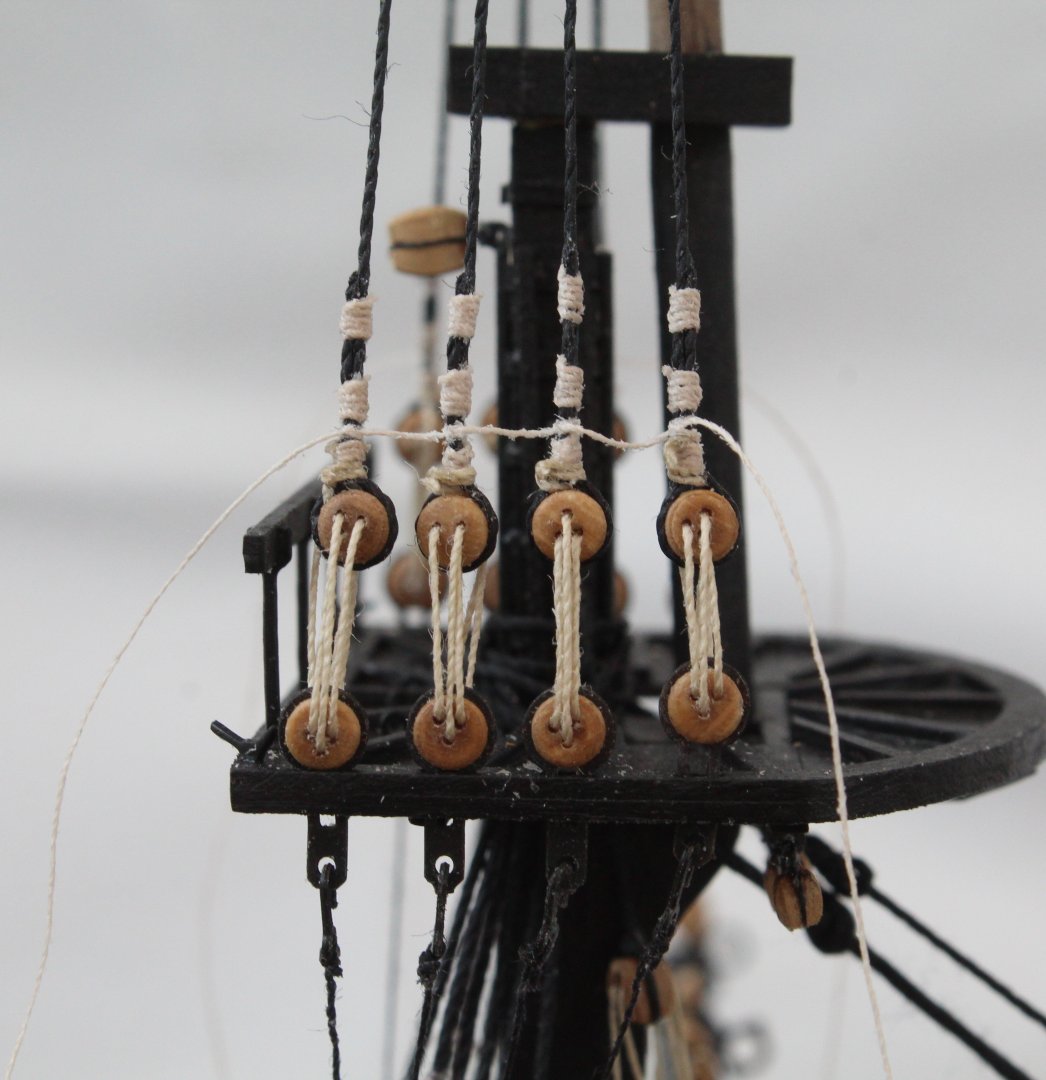
Time is still limited in the shipyard (aka sauna) due to the current heatwave in the UK meaning much more time is being spent lounging in the garden topping up my tan. 😎☀️ The work that has been undertaken is as follows: a) adding the belaying blocks for the main topsail stays as shown in the photo below, The free ends of the inter-block rigging will be tied off to a belying pin located on the pin rack on the foremast. b) adding the thimbles to the main topgallant stays which are linked to the thimbles located on the foremast main platform, as shown below. The free ends will be tied off around the inter-thimble rigging. c) Adding the blocks to the fore topsail stays as shown in the next two photos. The free ends of the inter-block rigging will be tied off to a belaying pin located on the pin rack at the front of the inner bulwarks,. The final set of photos shows the current build status. My next task will be to make, add and rig the two boomkins.

- 241 replies
-
- 7
-
-
- Vanguarrd Models
- Harpy
- (and 1 more)
-
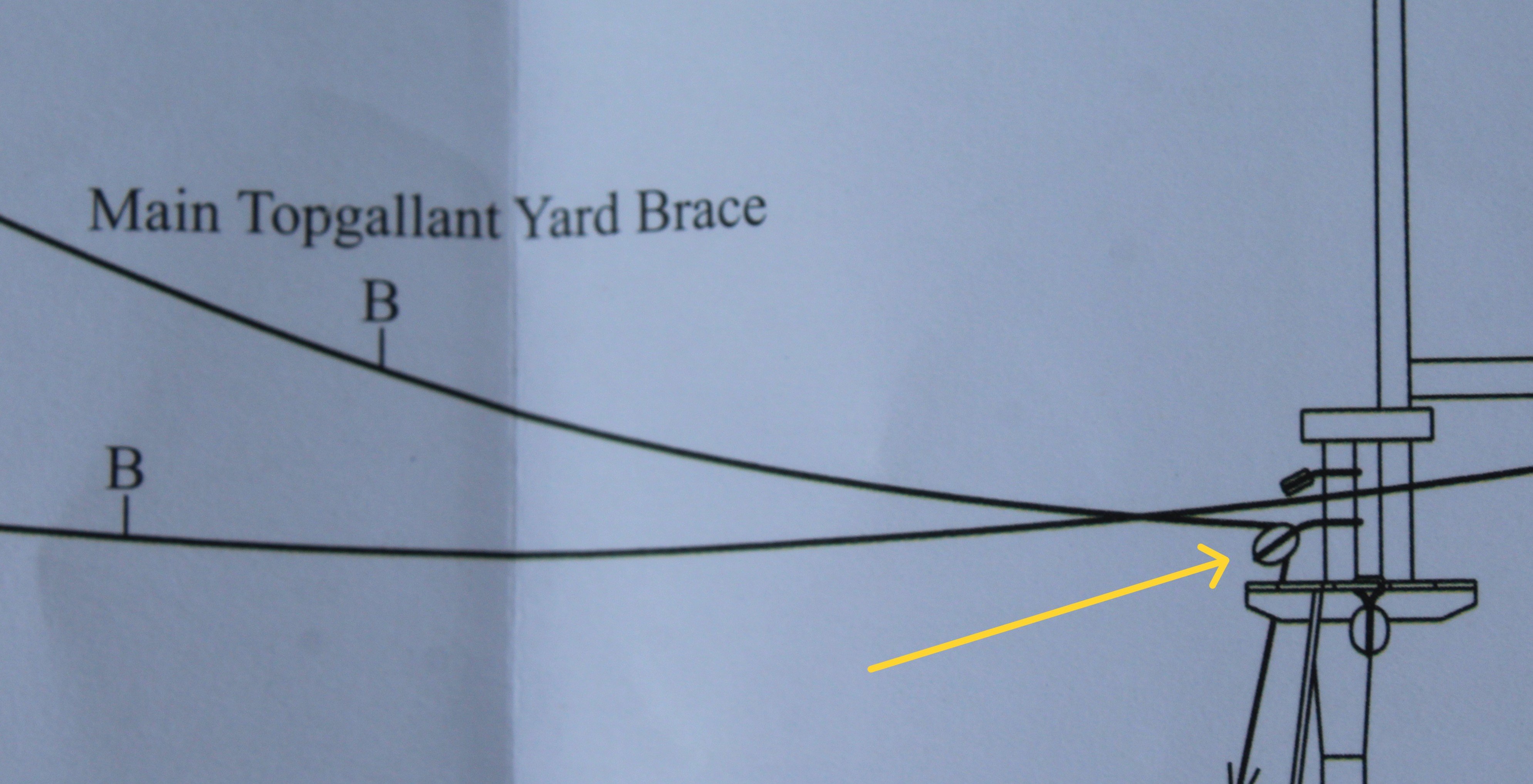
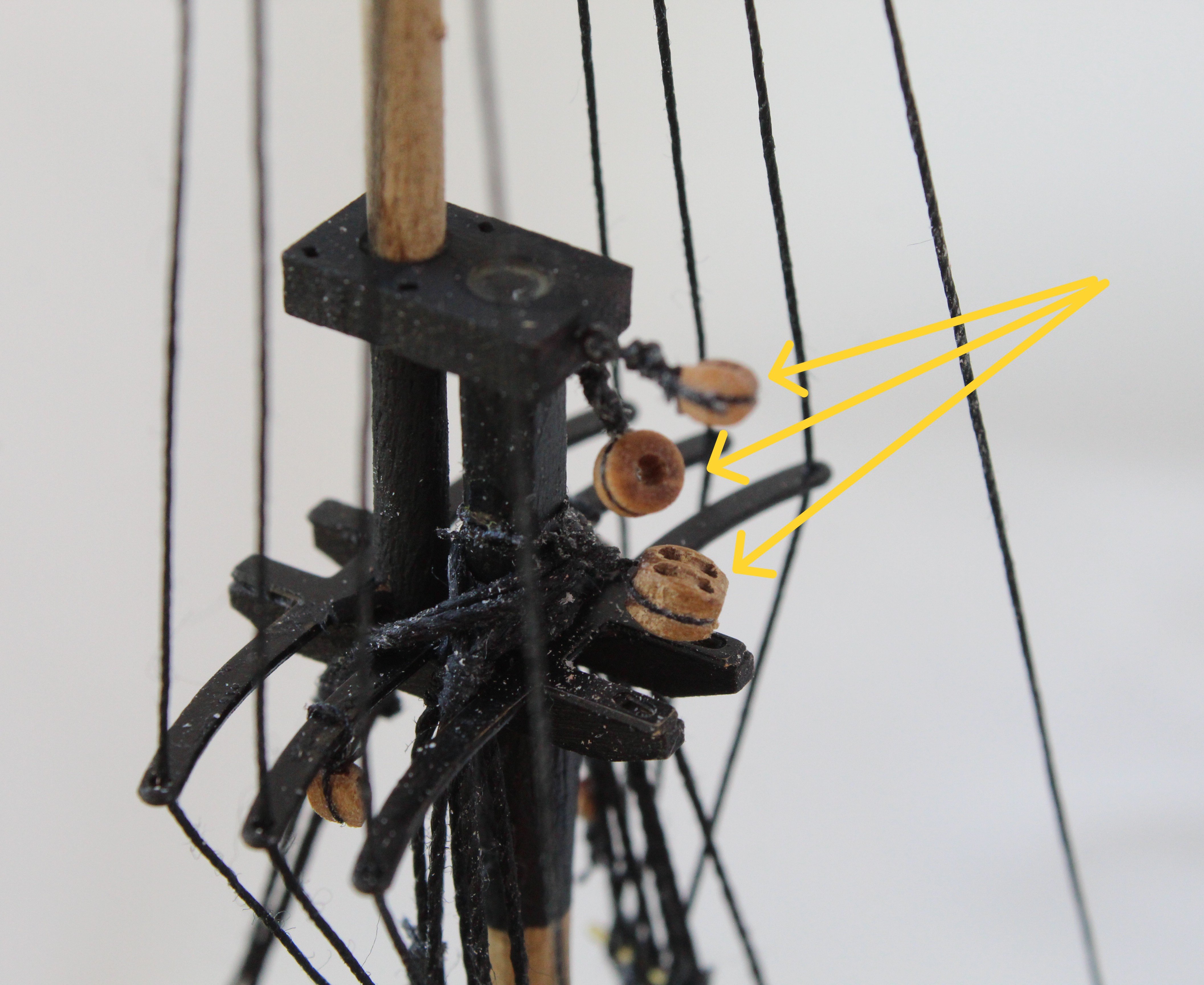
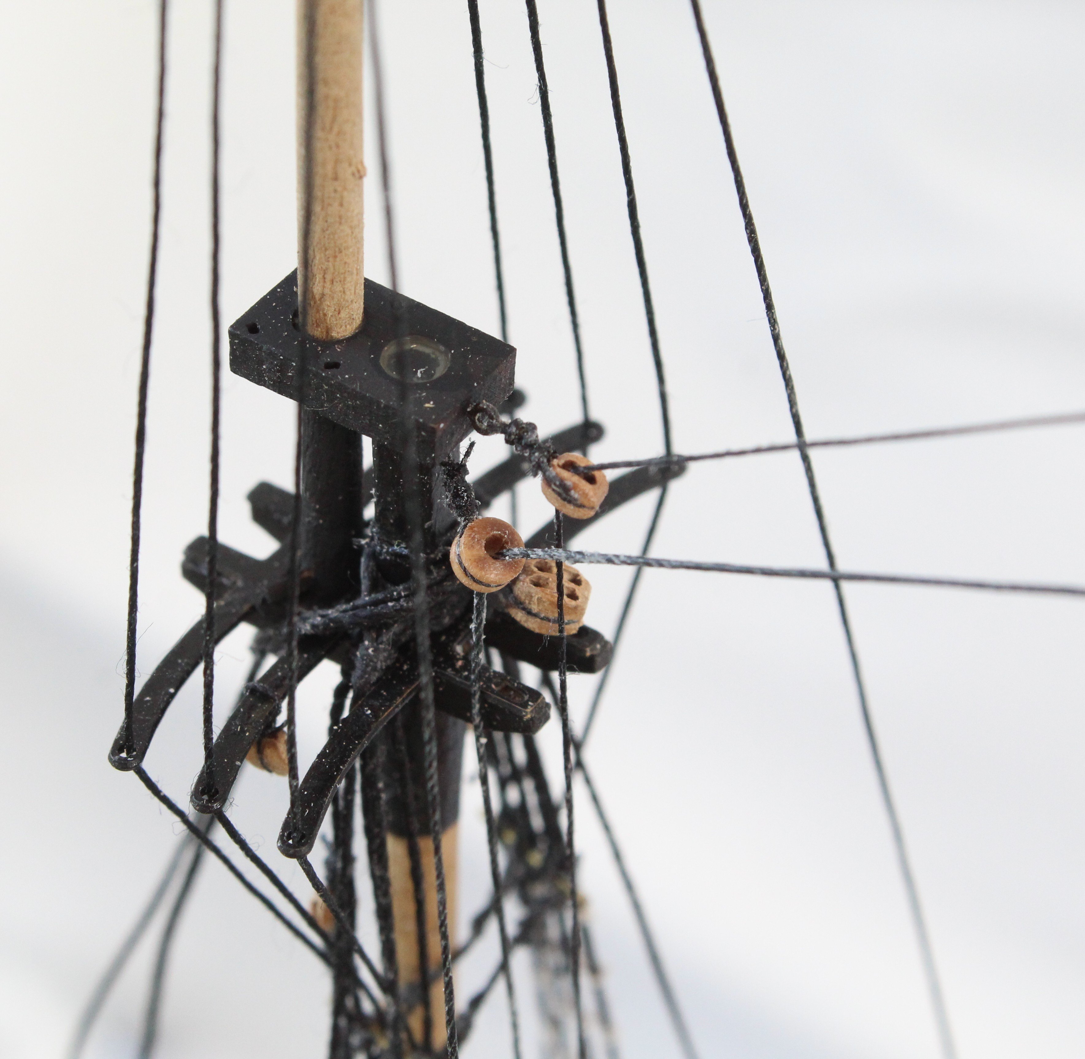
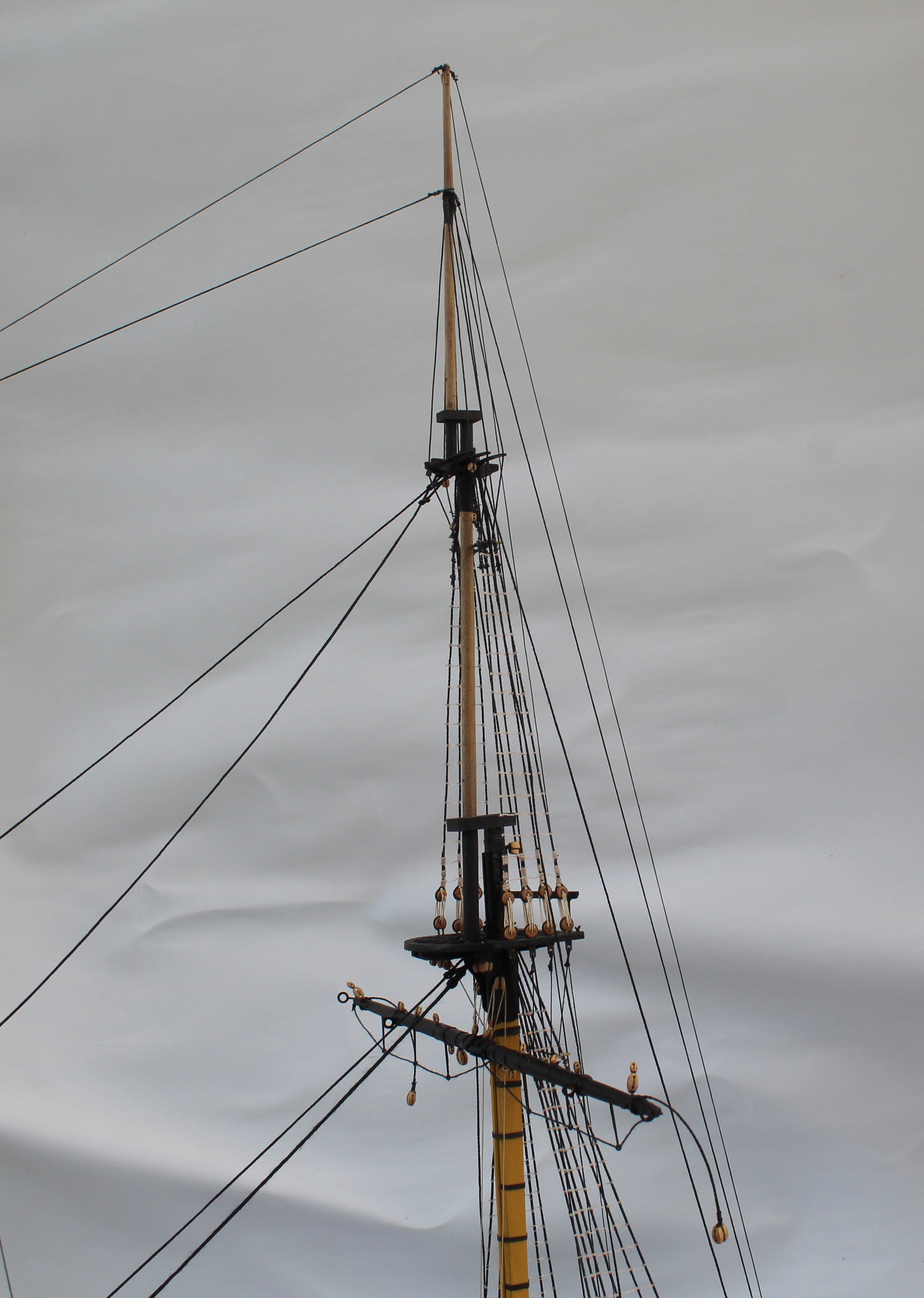
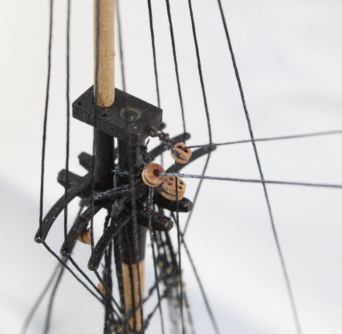
I have now completed adding the shrouds to both the main and fore topgallant masts. Both the main and fore topgallant mast stays have also been run in. I now have a number of rigged threads to belay. When looking at the plan sheets for the main topgallant mast stays I noted a slight anomaly. There is a 4mm double block fitted to the top of the fore topsail mast which is used for the main topgallant mast stay, as shown below. I could not understands why this was a double block and then noted that this double block is also used for the two topgallant yard braces which made much more sense. I decided to add an additional 3mm single block to the fore topsail mast cap for reeving the stay. The next two photos shows these blocks. The next two photos show the various back stays that are belayed to the channel. The next photo shows the main topgallant mast stays, which have been rigged but are waiting to be belayed. The final two photos shows the current build status.


- 241 replies
-
- 5
-
-
- Vanguarrd Models
- Harpy
- (and 1 more)
-
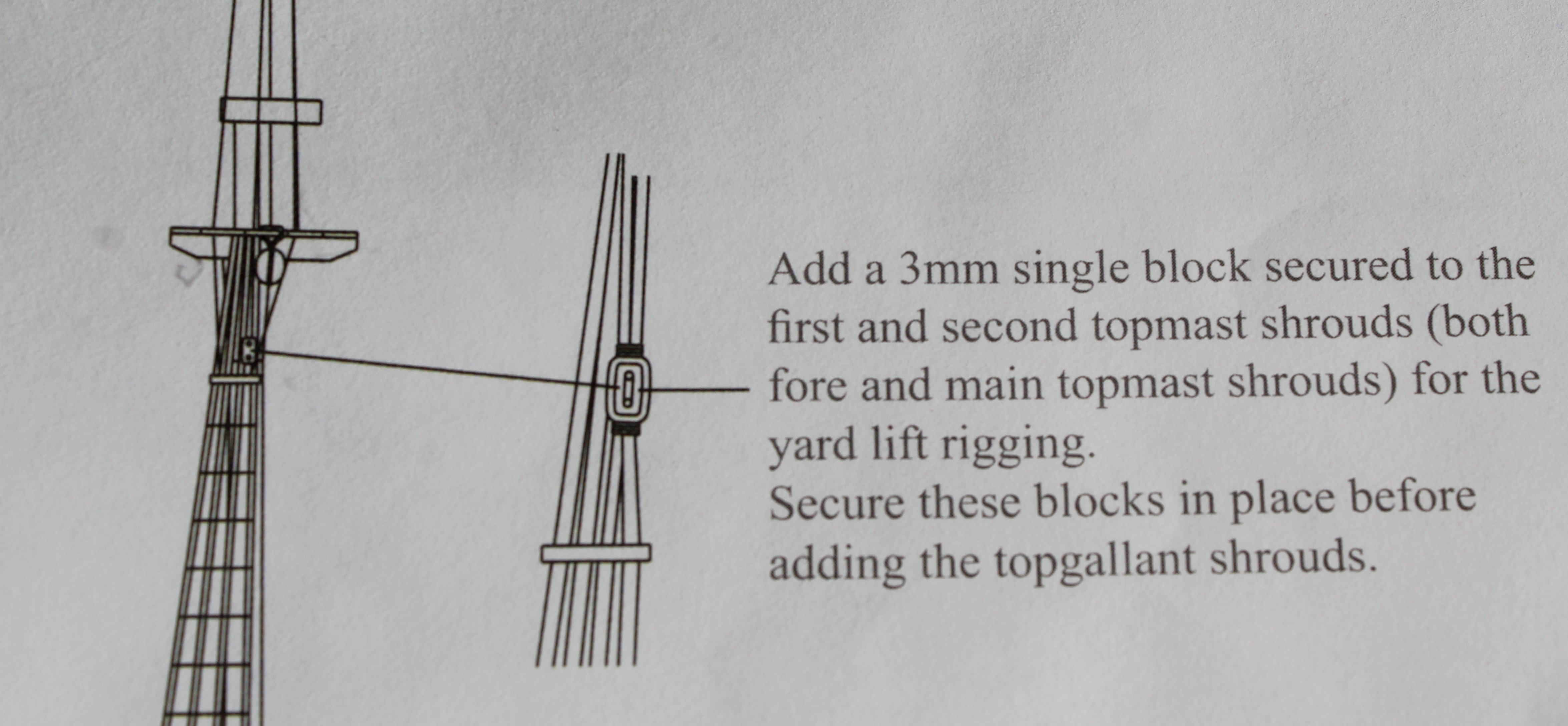
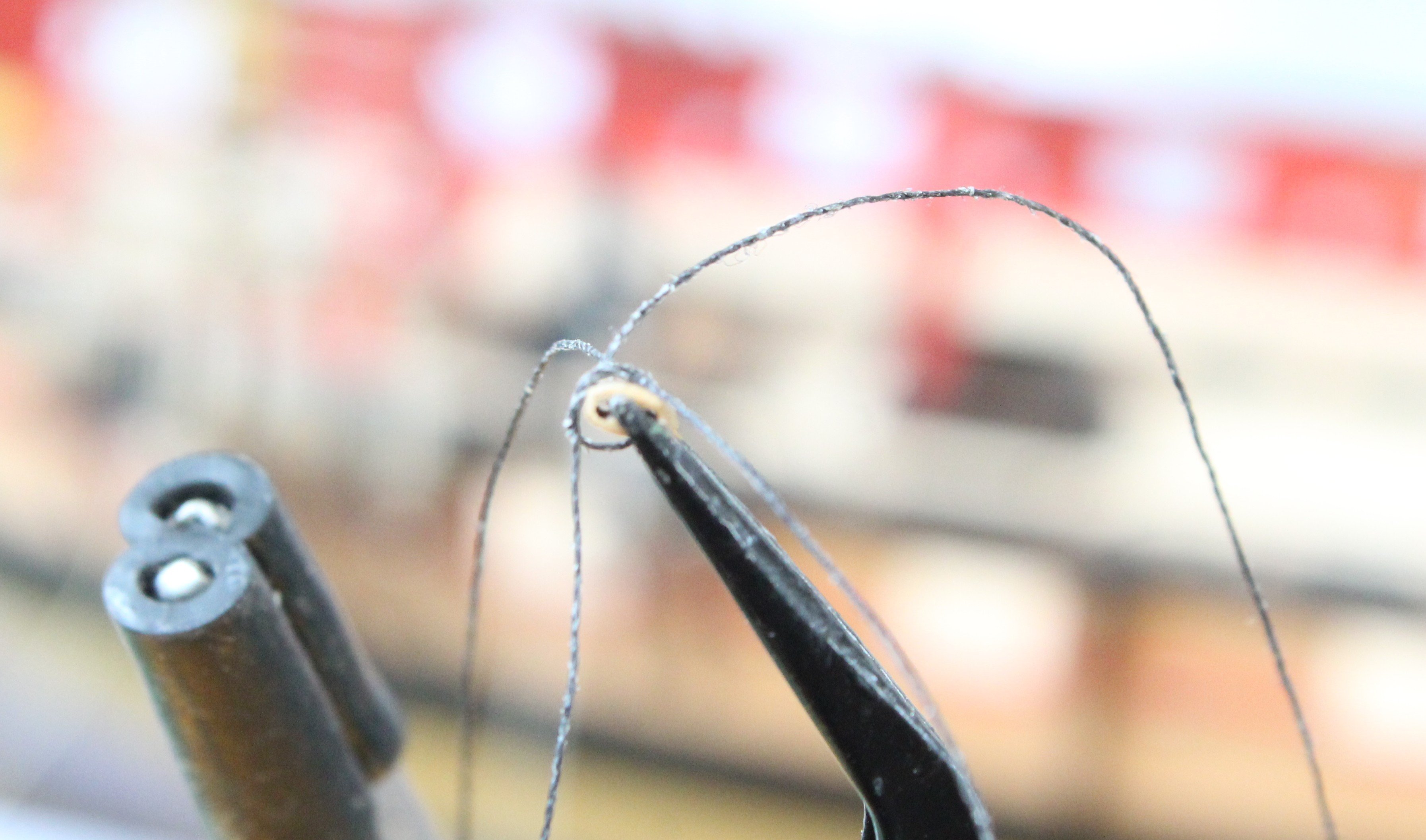
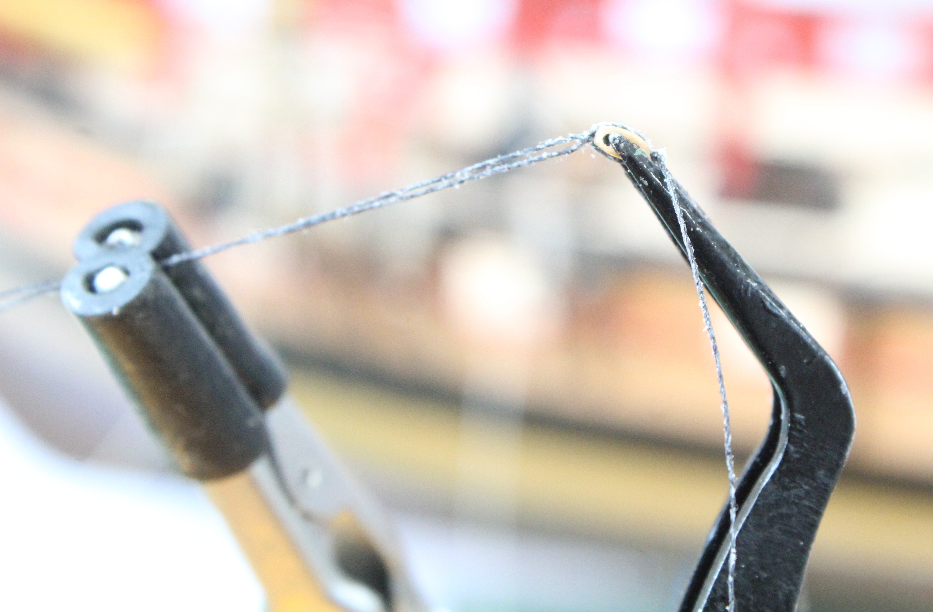
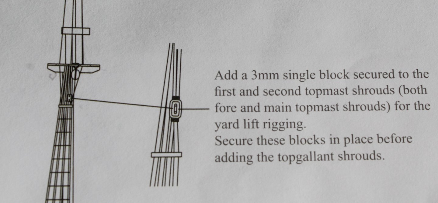
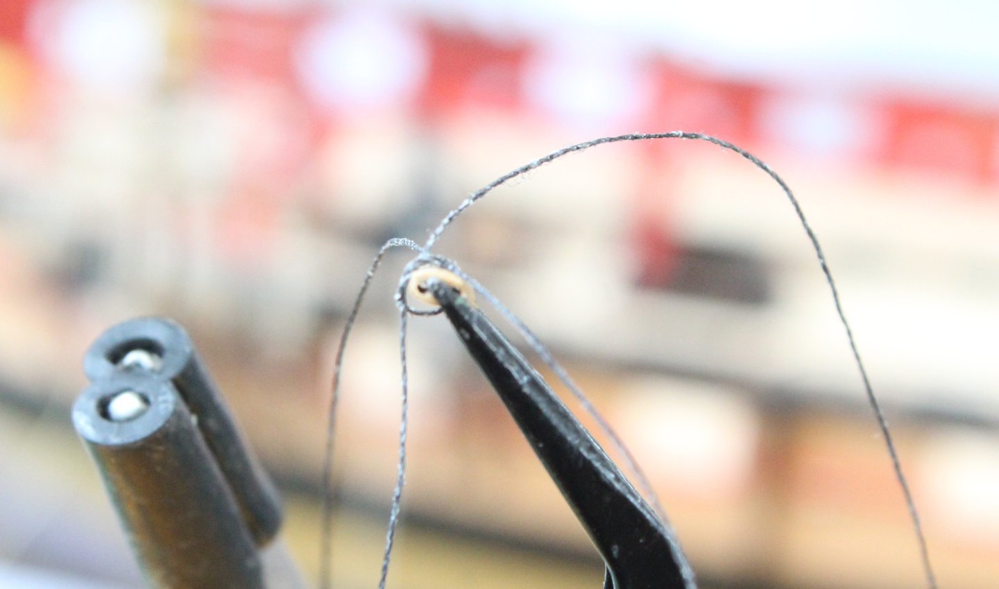
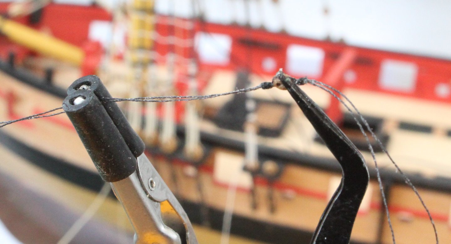
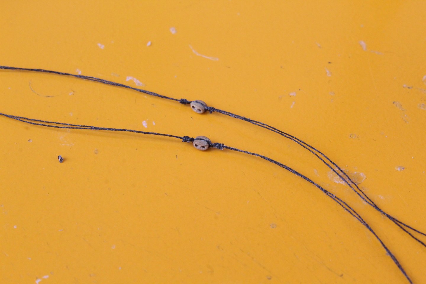
The next task undertaken was adding the shrouds to both the main and fore topgallant masts. This was a fairly straightforward task. I did fix the wayward catharpin which can be seen in the second photo. I did not look at the rigging plans properly as I missed the following note which I should have done before adding the topgallant shrouds. Thankfully this is not a show stopper error as I did find it possible to add these blocks with the topgallant shrouds in situ. There were not fixed in place as per the plan requirements but they are acceptable to me. I started the process of adding these blocks by seizing the 3mm blocks. I used two lengths of threads so I could have thread available at each end of the block. In the photo below the first thread has been wrapped around the block and held in place with a simple crossover knot. The second thread was inserted in the under the first thread as the crossover knot was tightened. With the thread held in the quad hands the first thread was seized, as can be seen below. The block was then reversed in the quad hands so the second thread could be seized, as shown below. The first two blocks are now ready to be added. The first block has been fitted.

- 241 replies
-
- 6
-
-
- Vanguarrd Models
- Harpy
- (and 1 more)
-
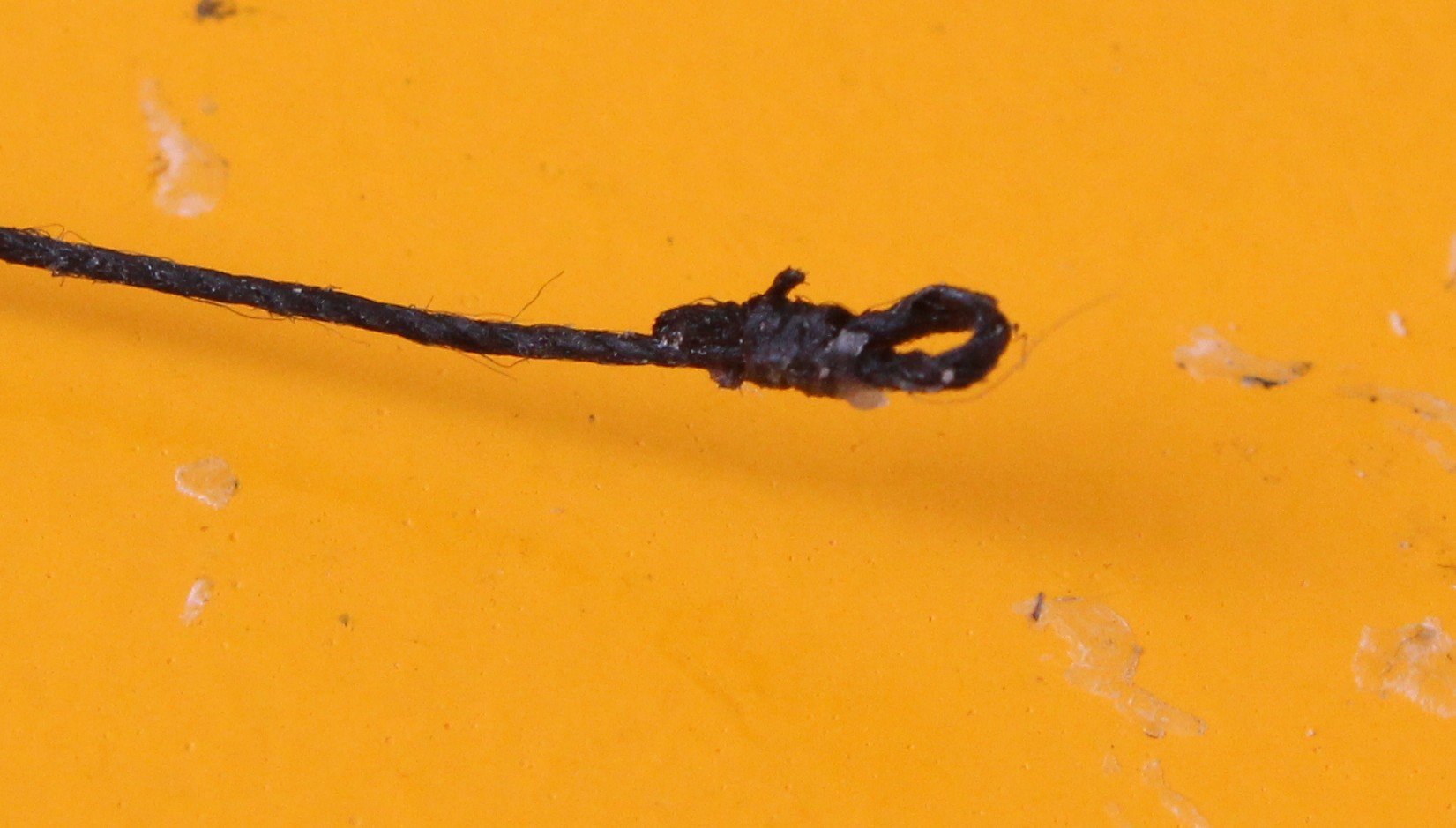
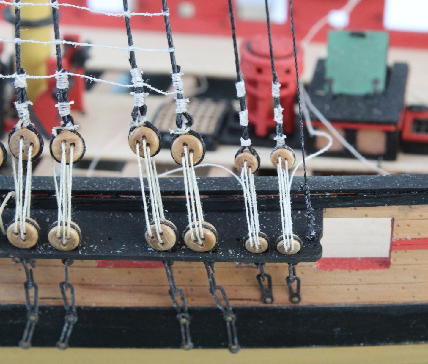
Over the last couple of days I have been working on the Royal and Shifting backstays.. The Royal backstay is a simple task as it drops down from the top mast (fore and main) and has a deadeye at the end which is rigged with a lanyard with a deadeye on the channel. The shifting backstay is a slightly more complicated arrangement. The shifting stay drops down from the top mast and has a 5mm block added to the end. It is then belayed to the channel via two 3mm blocks and two eyebolts. After I added a 5mm single block to the end of shifting stay I moved on to the 2 off 3mm blocks. A thread is passed through the 5mm block with a 3mm block on one end and the other end is belayed to eyebolt on the channel. With the first 3mm block is seized the thread is then added as shown in next set of photos. The other end of the first 3mm block also requires a length of thread adding. I used a needle to add the thread which is then seized as shown below. Another 3mm block is seized to an eyebolt. With the eyebolts added to the channels the various shifting stay threads were then run in They will be tied off later off in the rigging process.


- 241 replies
-
- 6
-
-
- Vanguarrd Models
- Harpy
- (and 1 more)
-
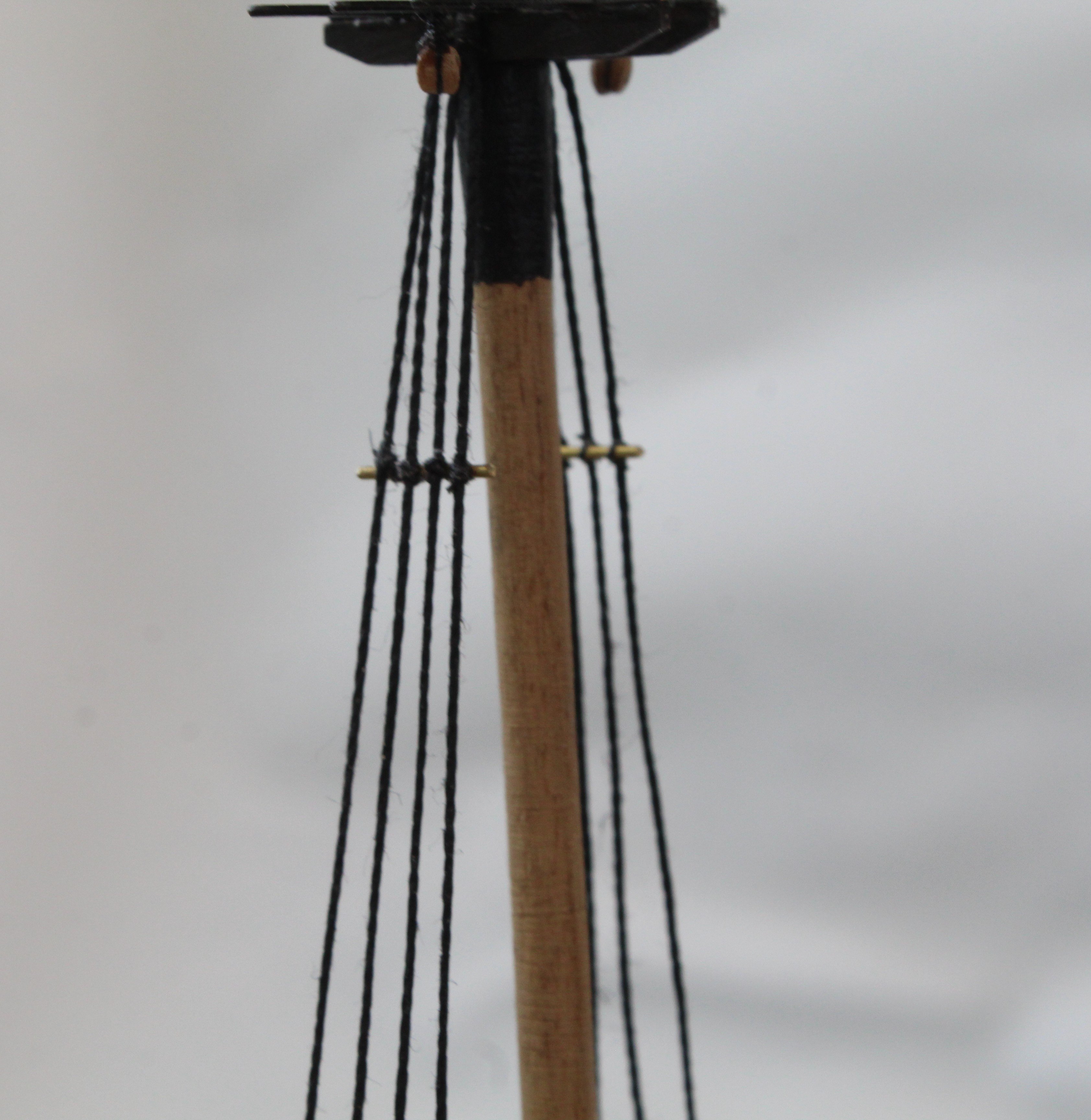
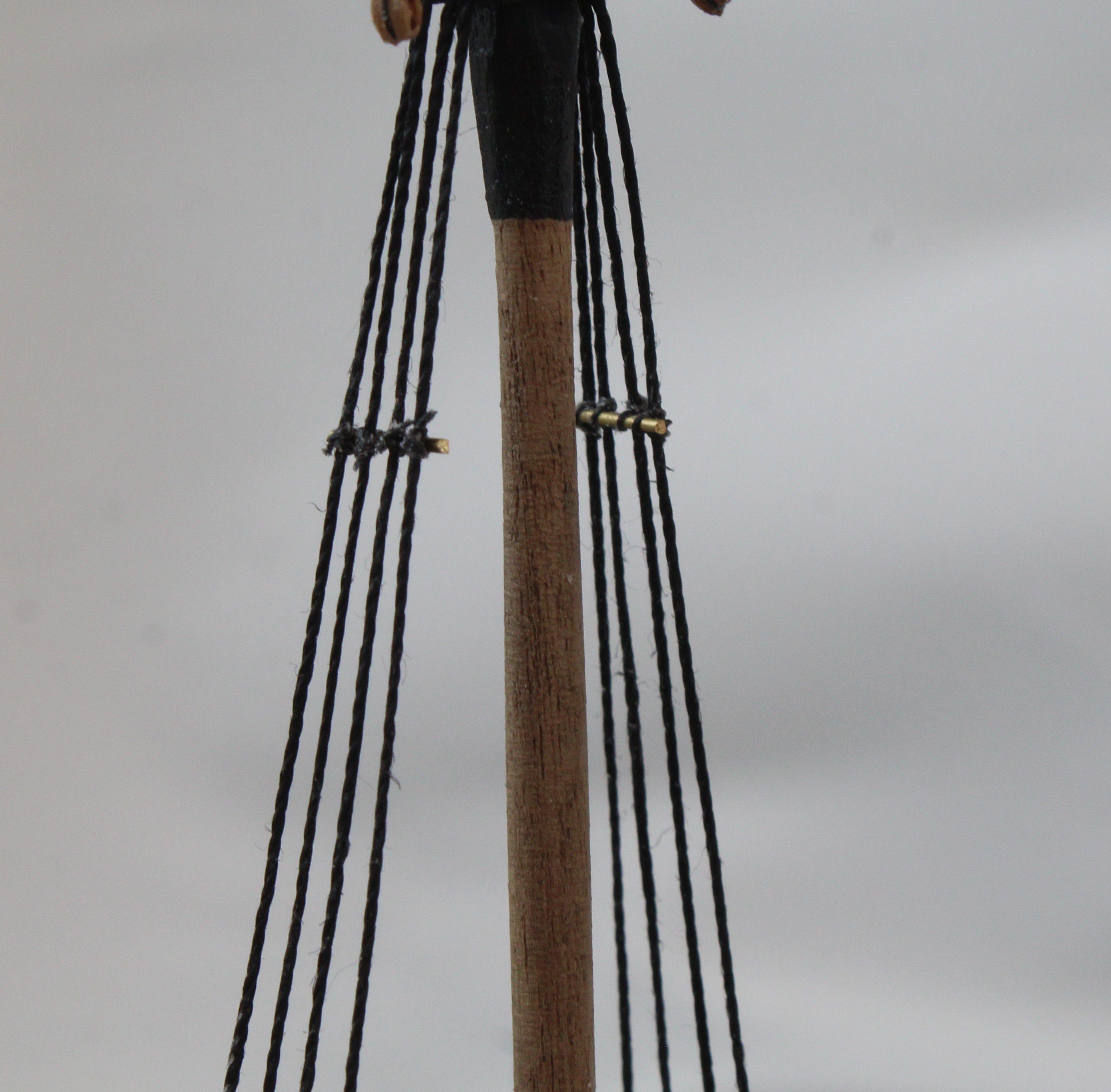
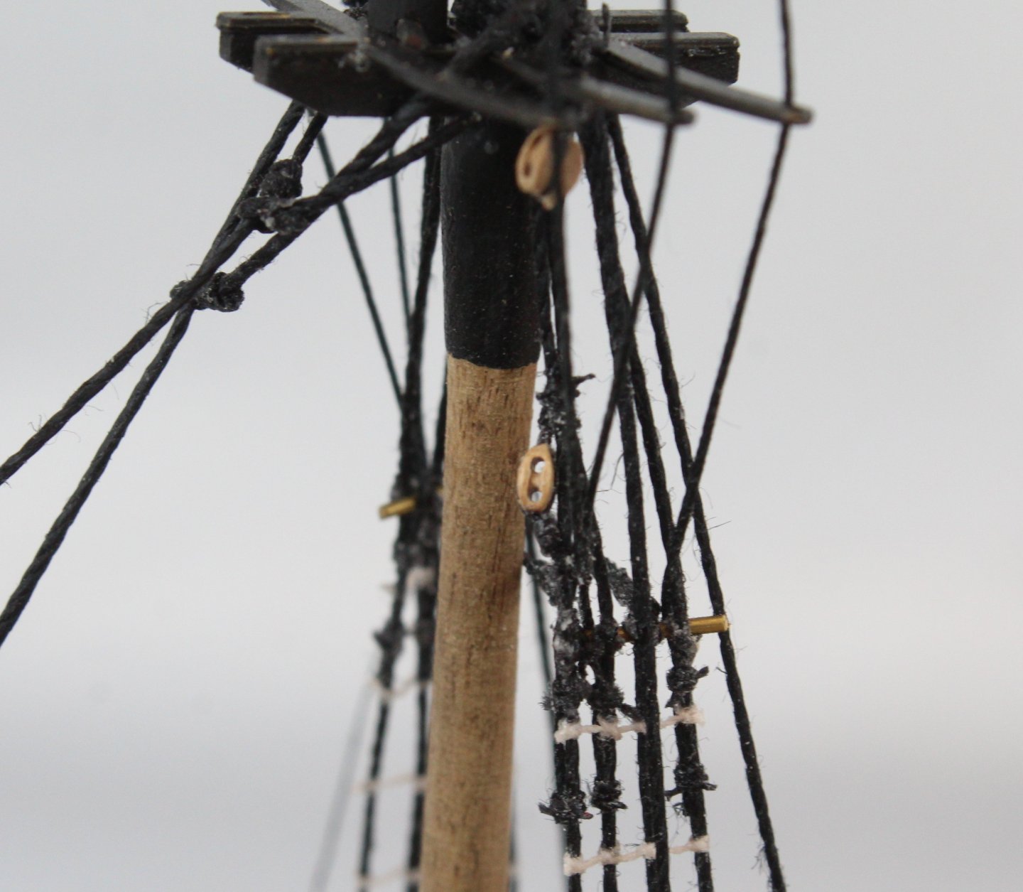
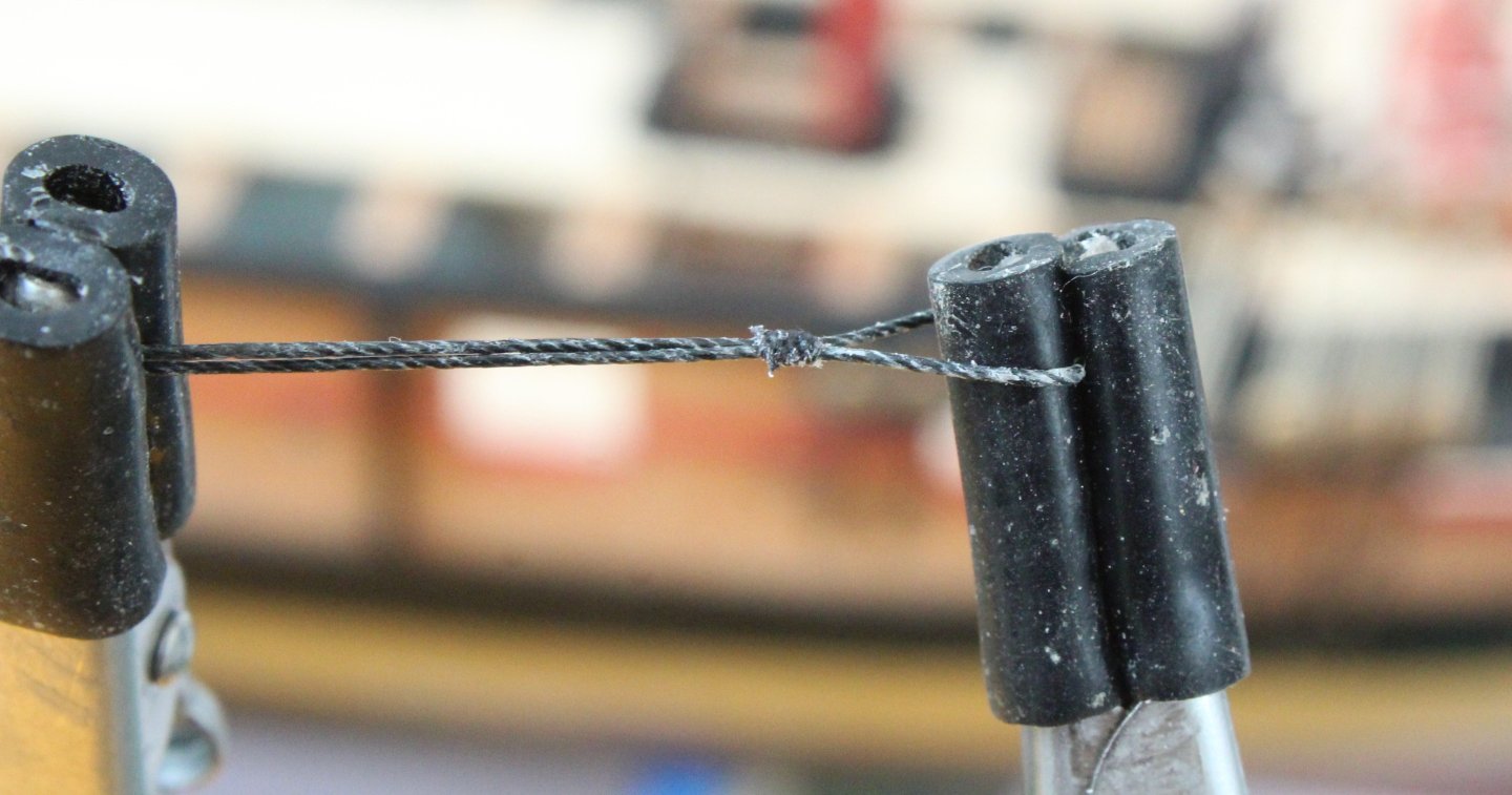
Before moving on to the next stage I realised I had not added the catharpins to the fore and main tops masts. I have refined my method in this respect which should ensure they are all made to the correct length, 2 off required for each topmast. I started the process by making a loop in one end of the thread. The thread is wrapped around a 1mmD copper bar, held in the quad hands and the seizing is then added. I then made a jig, using two lengths of 1mmD copper bar set to the required distance. The catharpin thread is then placed over one of the copper pins. The other end of the thread is wrapped around the other pin and then held in place using the quad hands, as can be seen below. It is then a simple task to add the seizing so the second loop is formed. It did not take long to make the four catharpins. I did add a small amount of ca clue along the length to stiffen them. The final task was to secure these to the shrouds. A length of thread was secured to each catharpin loop using a simple reef (square) knot. The thread were then passed around the futtock stave and toed off, once again using a reef knot. The excess threads were then cut off.


- 241 replies
-
- 9
-
-
- Vanguarrd Models
- Harpy
- (and 1 more)
-
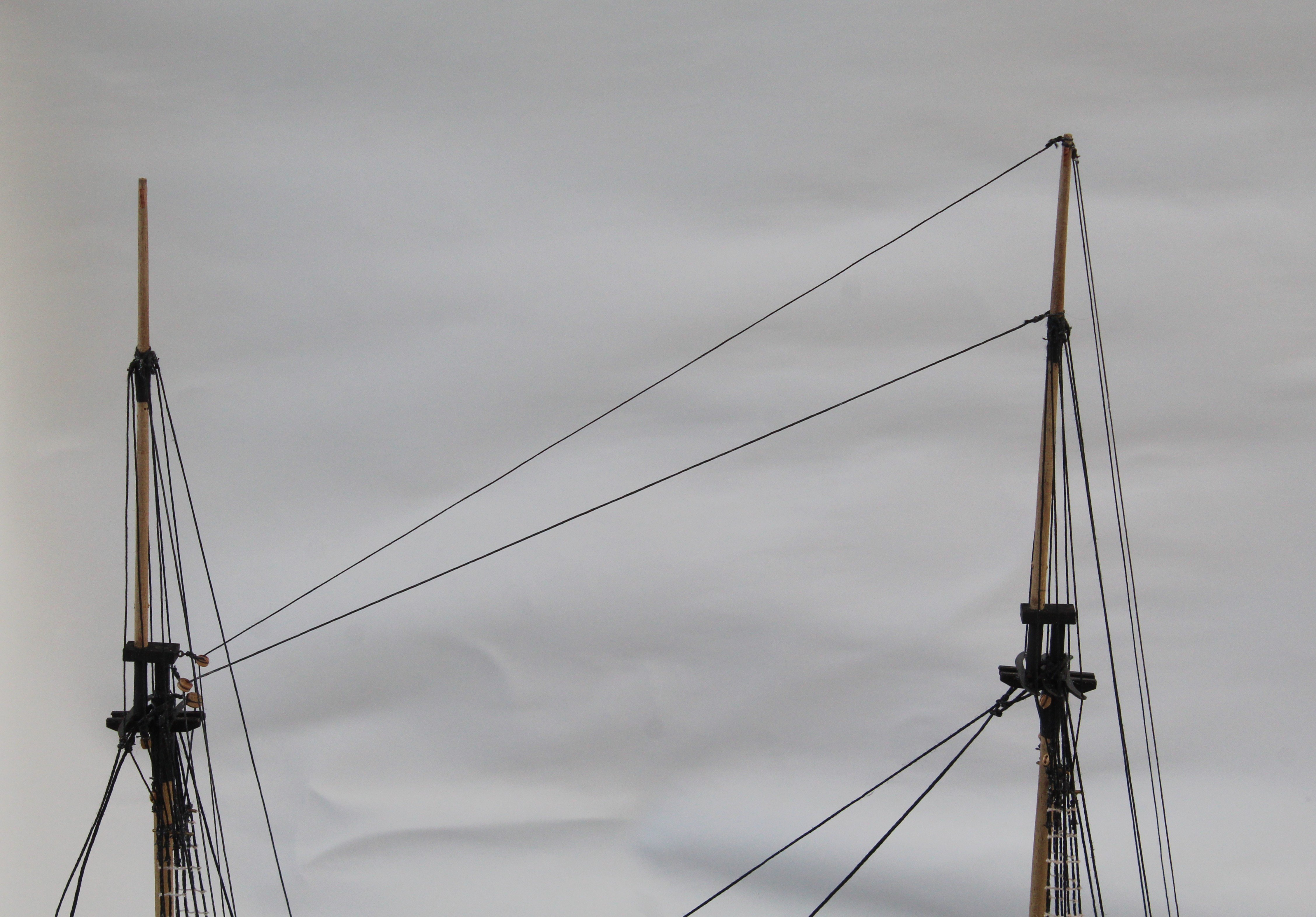
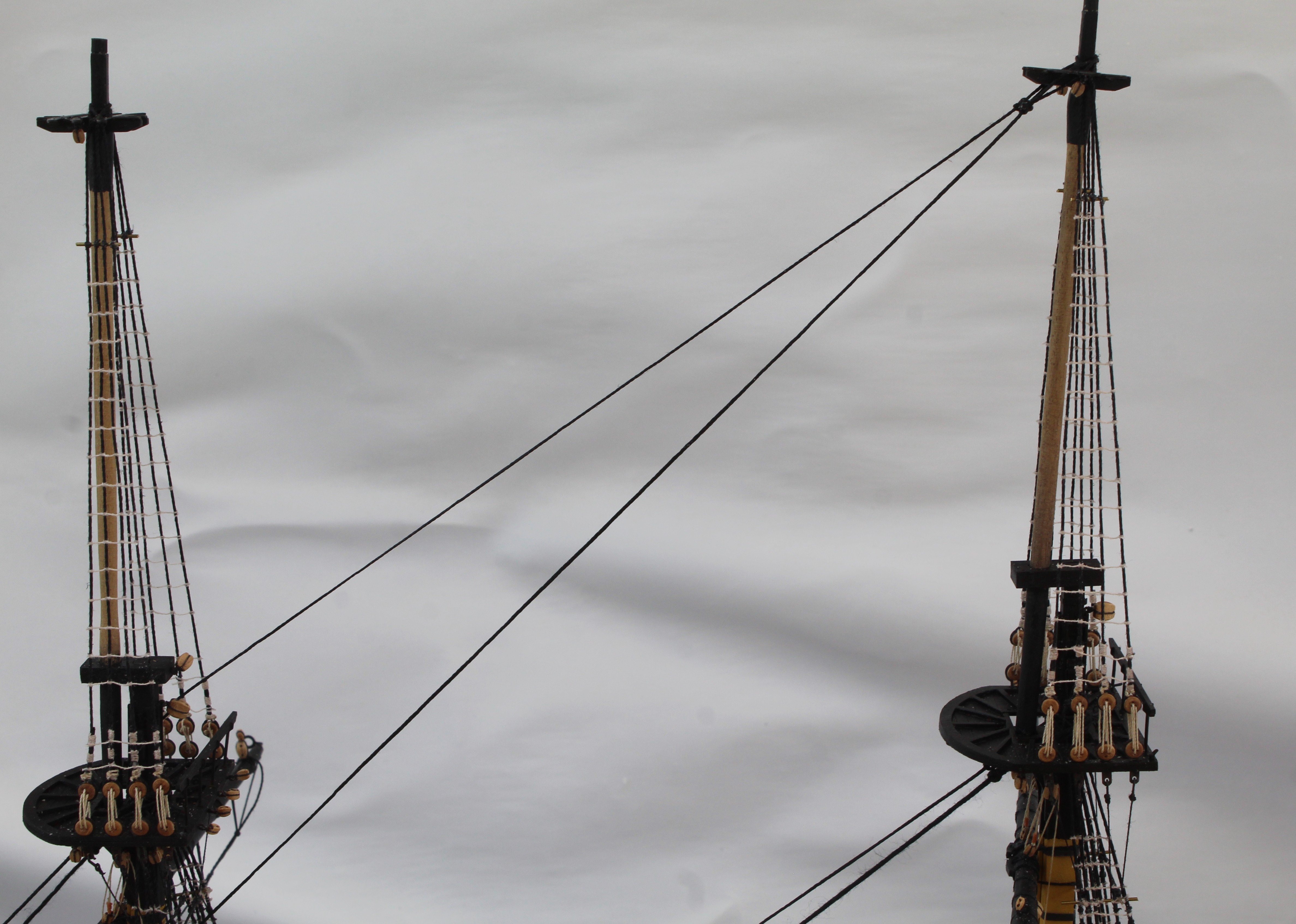
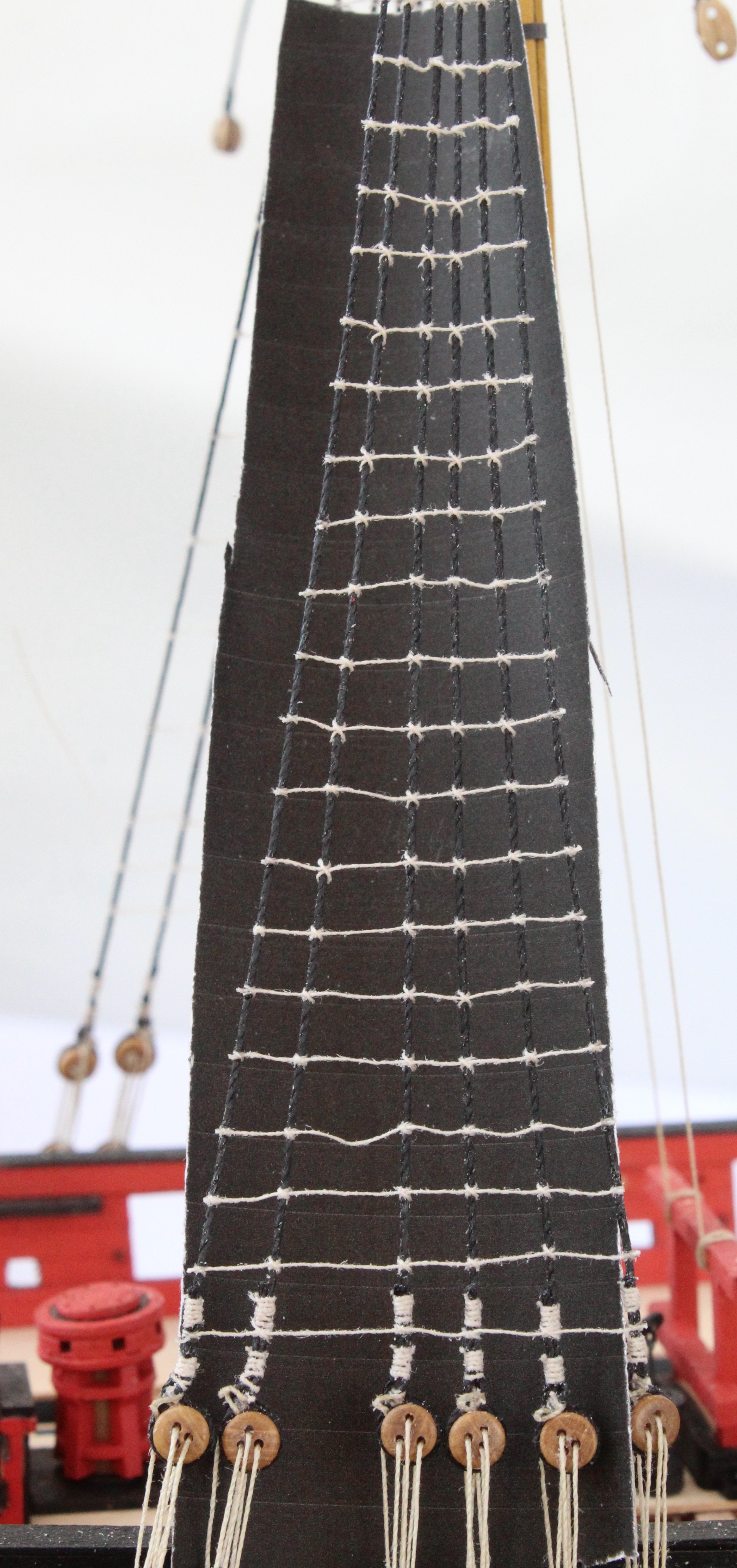
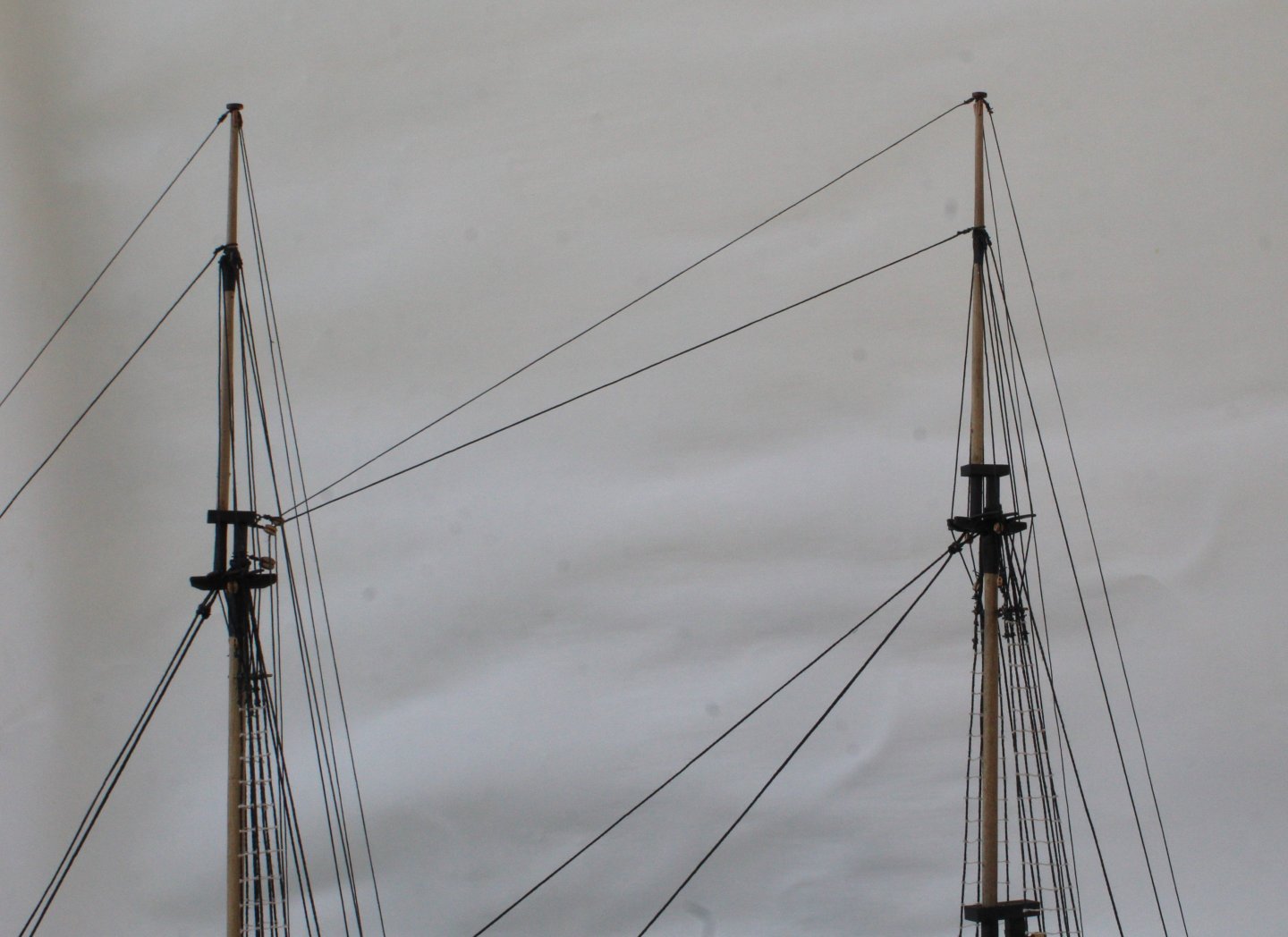
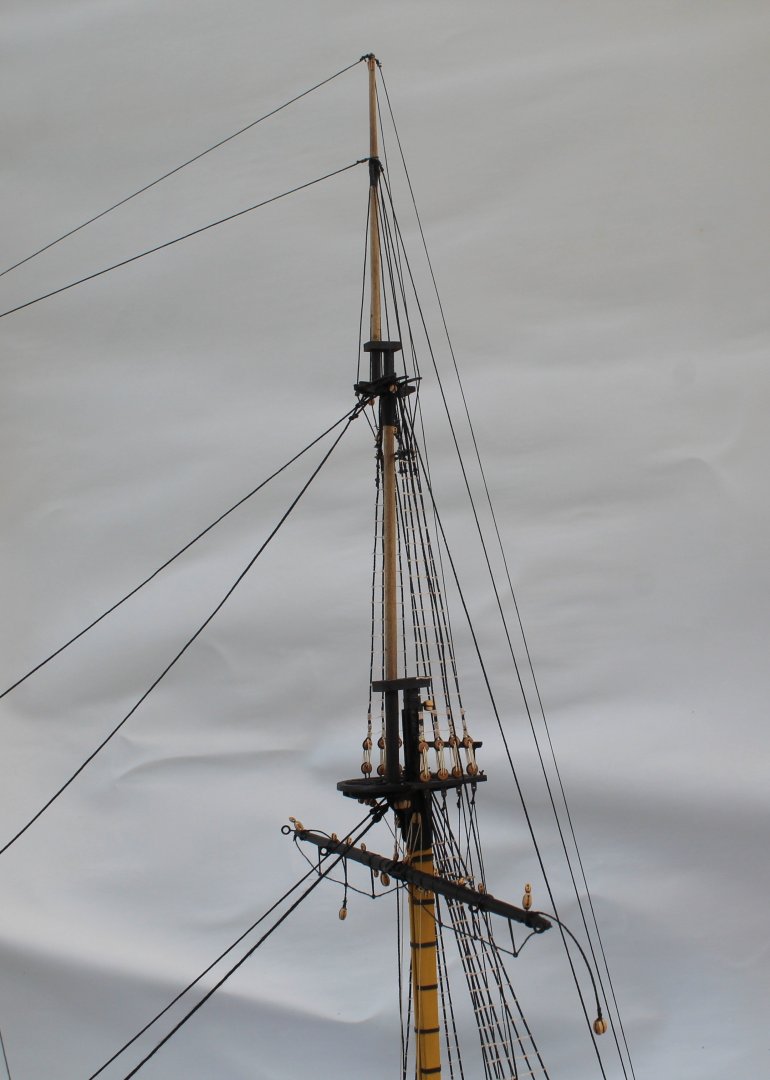
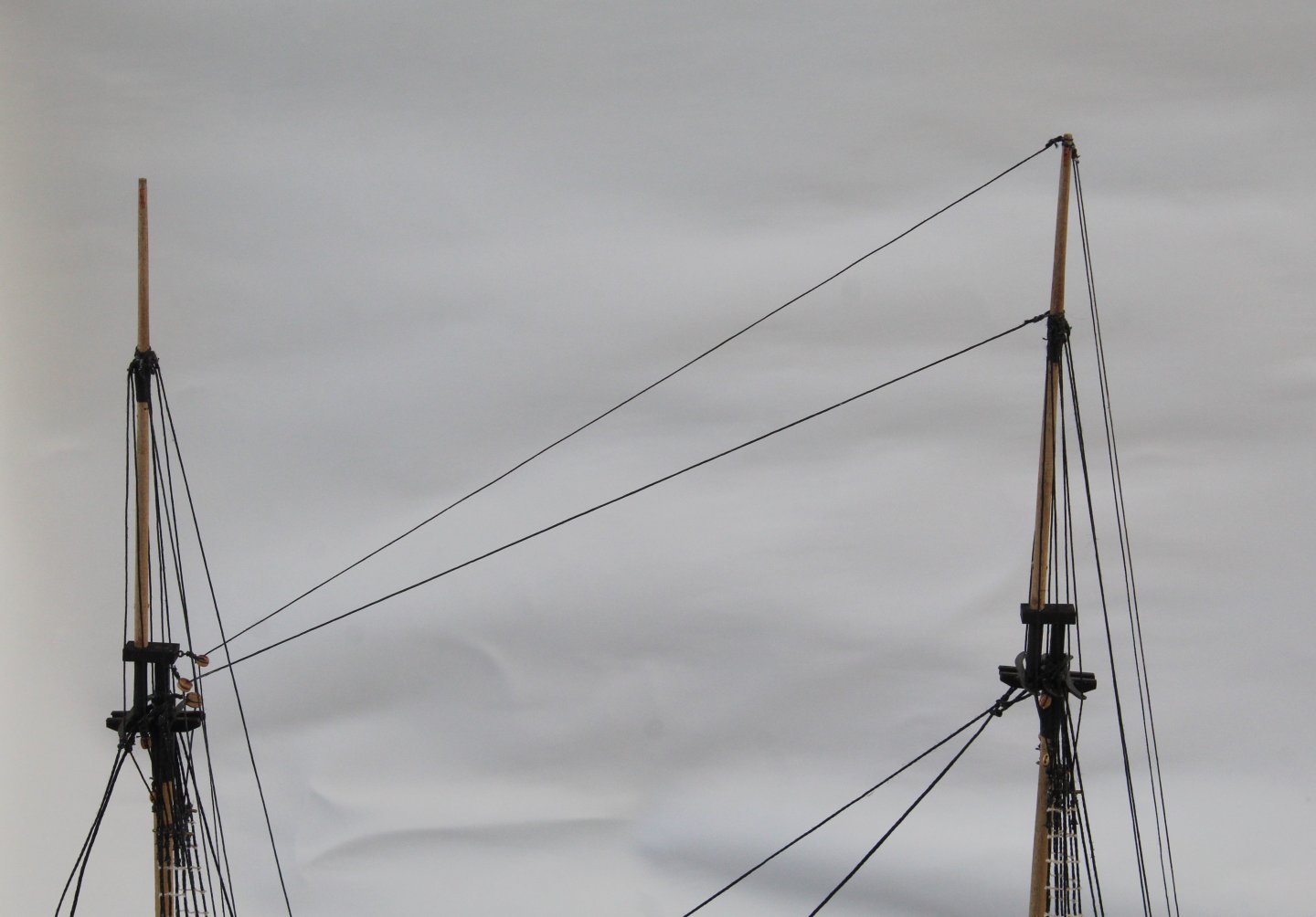
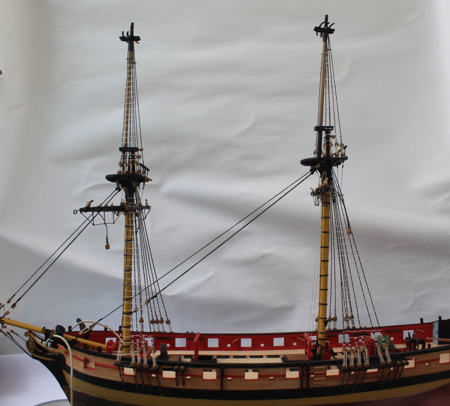
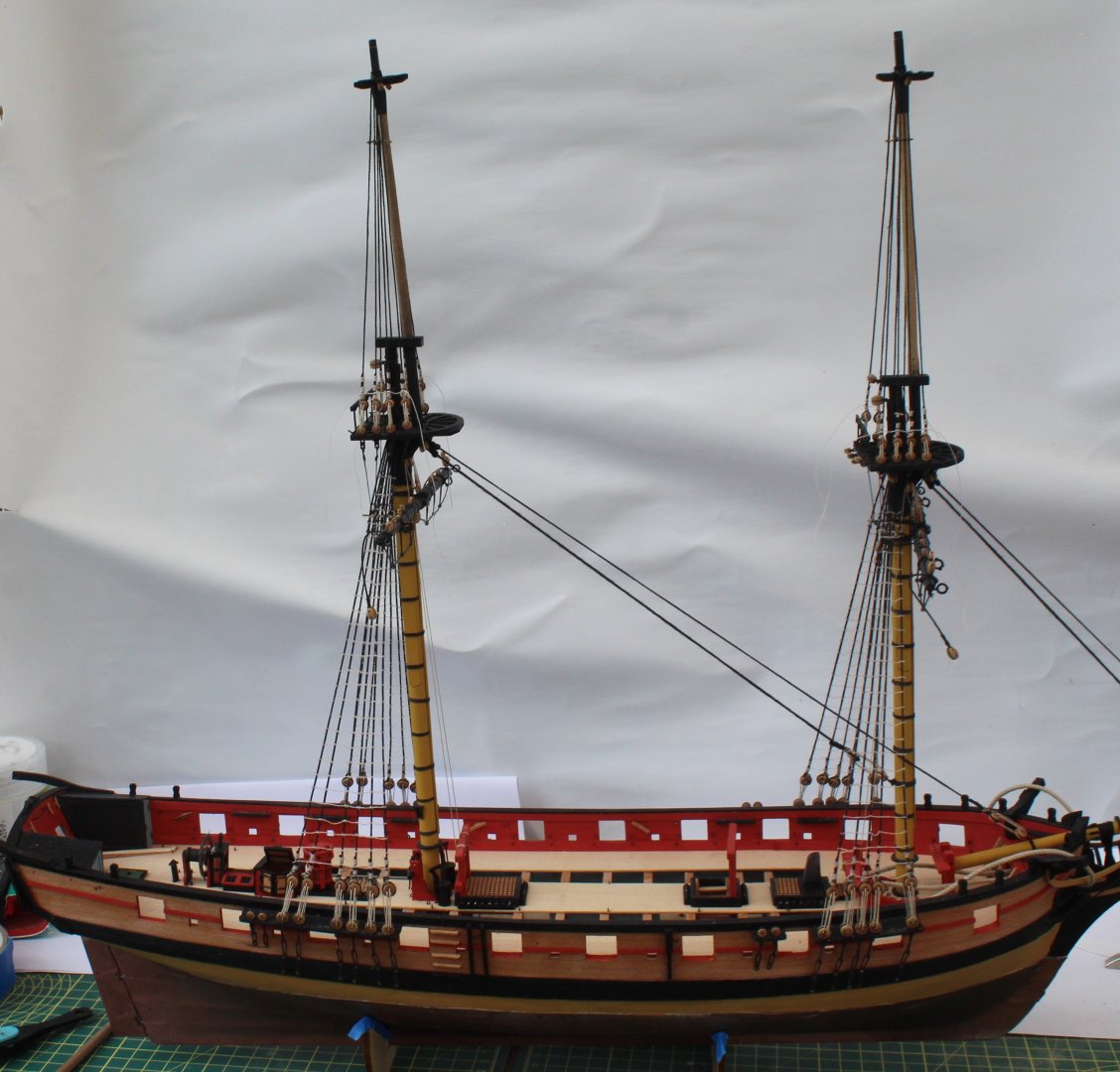
I have completed adding the ratlines to both the fore and main topmasts. Fore topmast Main topmast Next I started to add the main and fore topmast stays and preventor stays. Main topmast The main topmast stay and preventor have been fed through the blocks located on the fore mast and are now ready to be belayed. The final photo shows the current state of the build.


- 241 replies
-
- 9
-
-
- Vanguarrd Models
- Harpy
- (and 1 more)
-
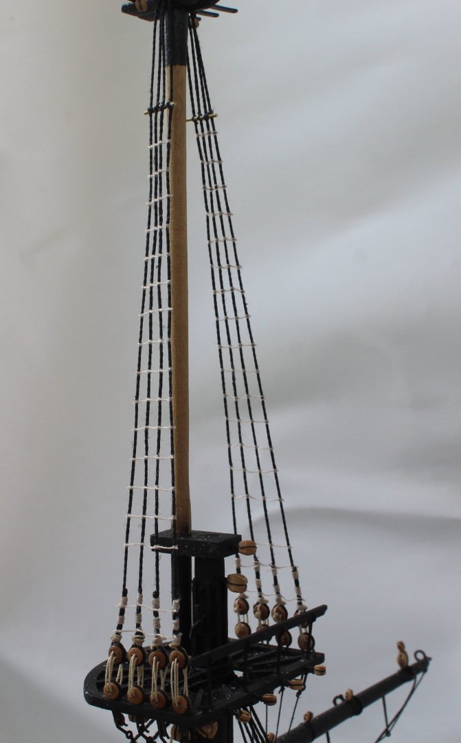
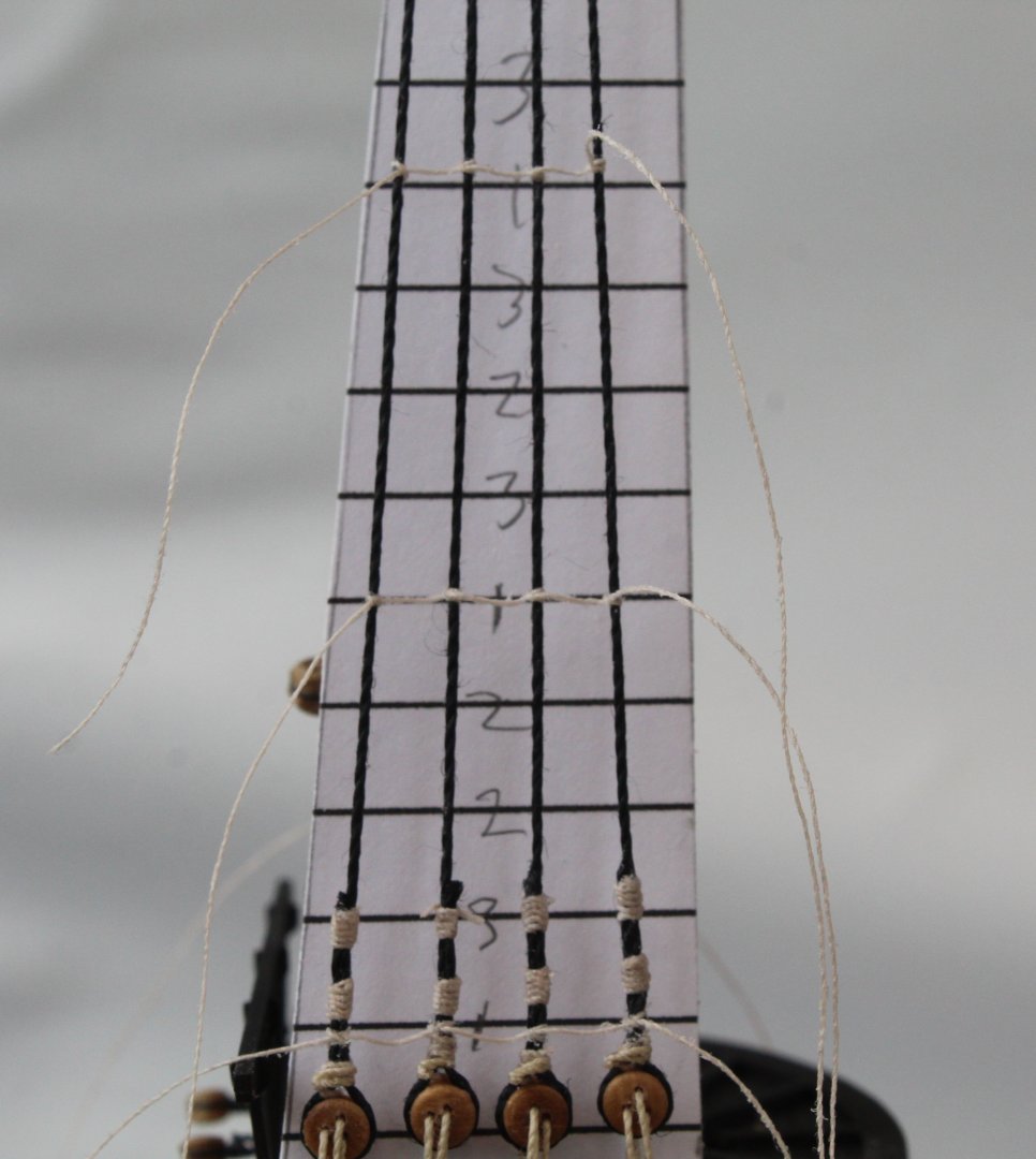
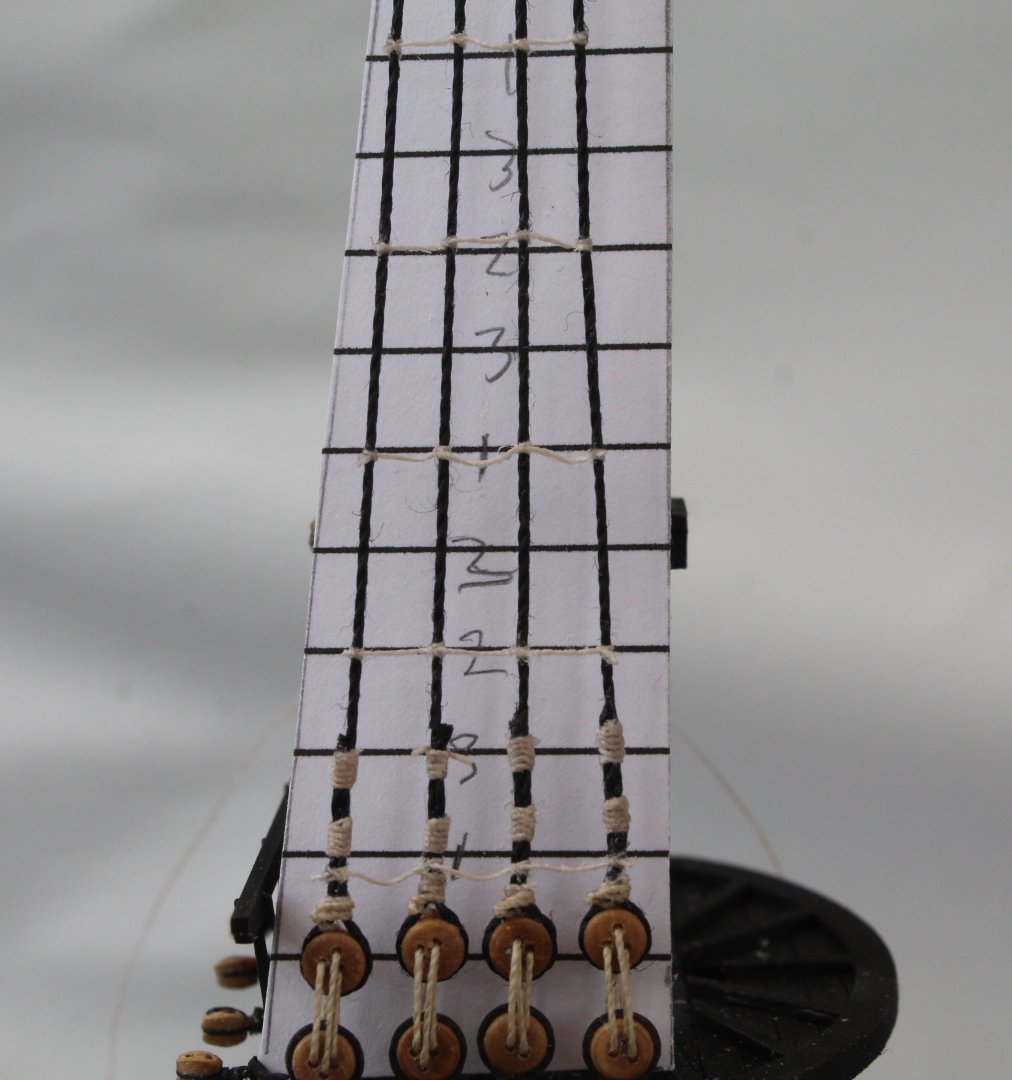
Work is still progressing on the fore and main top mast shrouds. The futtocks staves have now been added. Fore topmast Main topmast Harpy The next set of photos does not show my workmanship in the best light. The next task is adding the ratlines. I have added all the bottom most ratline to both the fore and main topmasts. I can now work my way upward adding every 5th ratline, as indicated by the 1's on my template. I did mark one of the 3's as a 2 on my template as can be seen below but I did correct this. Next I add the next set of every 5th ratline, which are marked as the 2's on my template. The final task is to add all the remaining ratlines, which are the 3's on my template. I have made a start on adding the 3's.

- 241 replies
-
- 13
-
-
- Vanguarrd Models
- Harpy
- (and 1 more)
-
I have not made much progress over the last few days as I have been refining my method for attaching the deadeyes to the shrouds. After a bit of adjustment I now have a way of working which suits me and appears to yield good results. In simple terms a deadeye is seized in a shroud line before off boat, with a rough approximation of the required position made. With the shroud line then placed on the mast the position of the deadeye can be checked. I have found it is possible to slide the deadeye up or down, as necessary. Once I am happy with the position of the deadeye the upper two seizing can be added, again off boat. As each shroud pair is complete and placed on the mast the lanyards can then be added.
- 241 replies
-
- 13
-
-
- Vanguarrd Models
- Harpy
- (and 1 more)
-
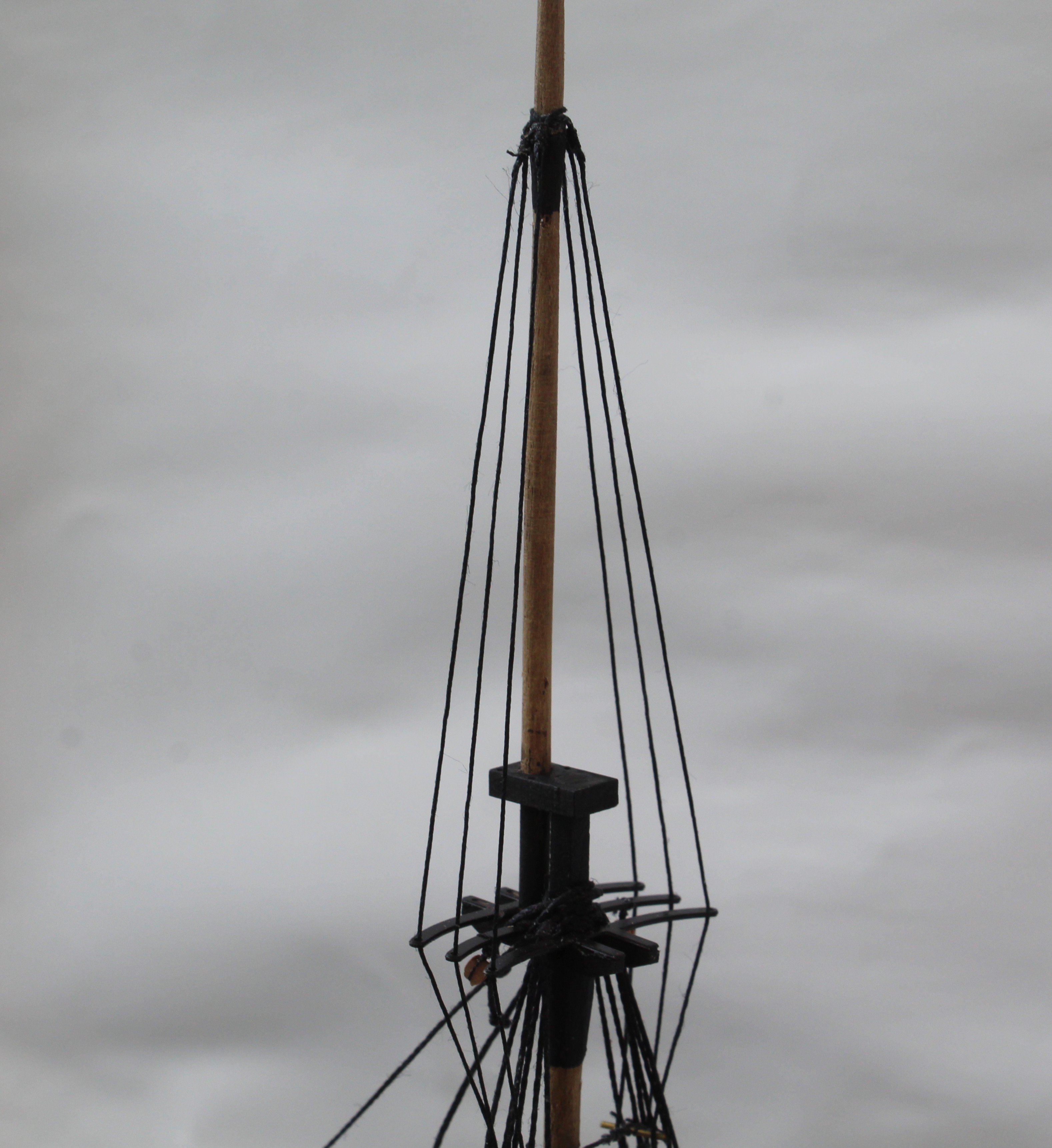
I have started work on the topmast shrouds. The first task was to make all the shroud pairs for both the main and fore mast. I used a spare piece of dowel to set the loop to the right size so it will fit nicely over the topmast. I have decided to try an experiment with regards to adding the deadeyes to the shroud lines. With the first shroud lines in place I passed some thread through to indicate where the top edge of the deadeye should be positioned so that lanyard distance between the deadeyes would be approx. 6 to 7mm. The deadeye was then sized,, it was much easier to do this off the boat. With a test fit of the completed first shroud pair I am happy with how the method makes the task much easier however I made a slight miscalculation with the position of the shroud deadeyes, as the lanyard spacing is approx. 10mm which is too much.
- 241 replies
-
- 13
-
-
- Vanguarrd Models
- Harpy
- (and 1 more)
-
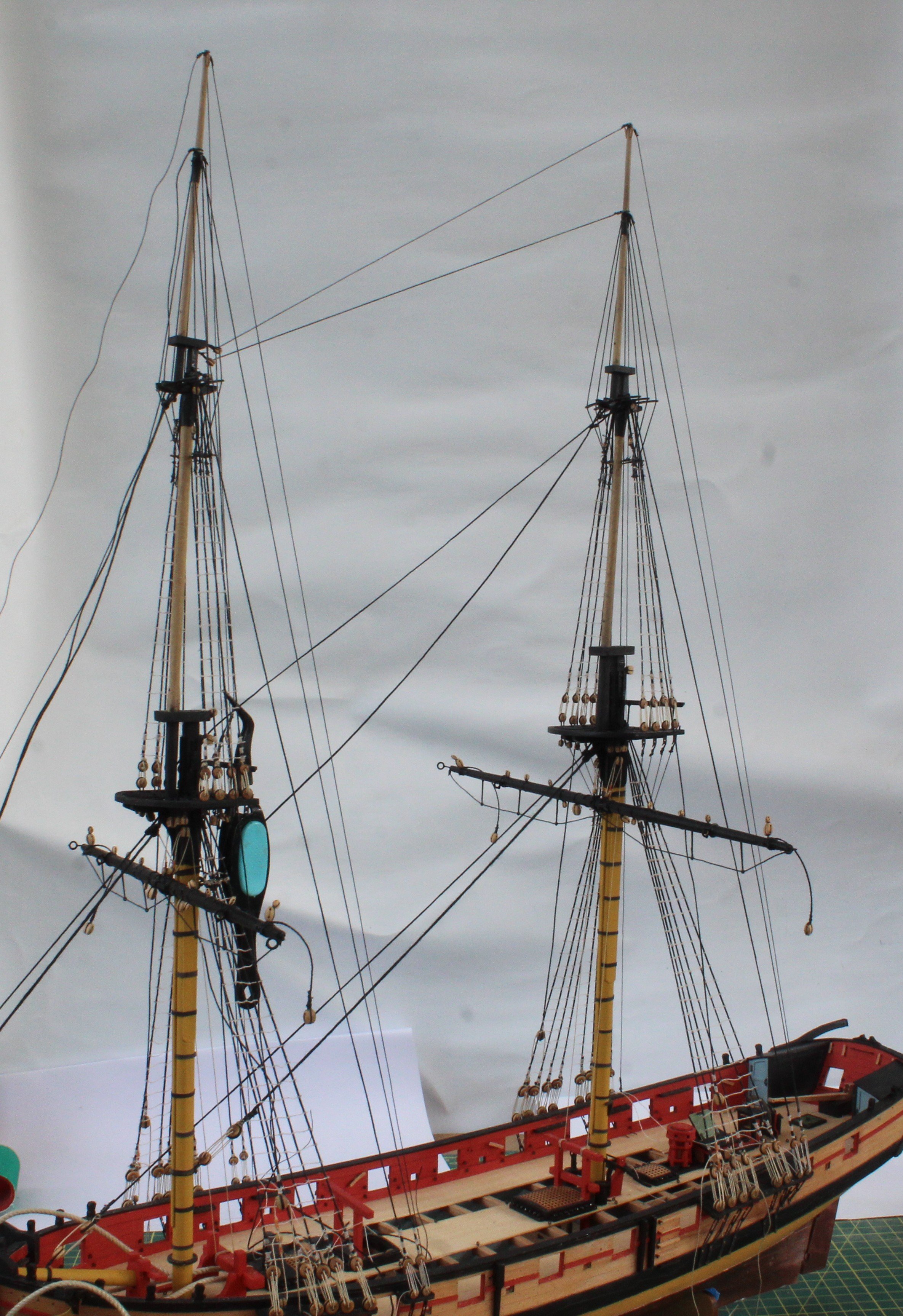
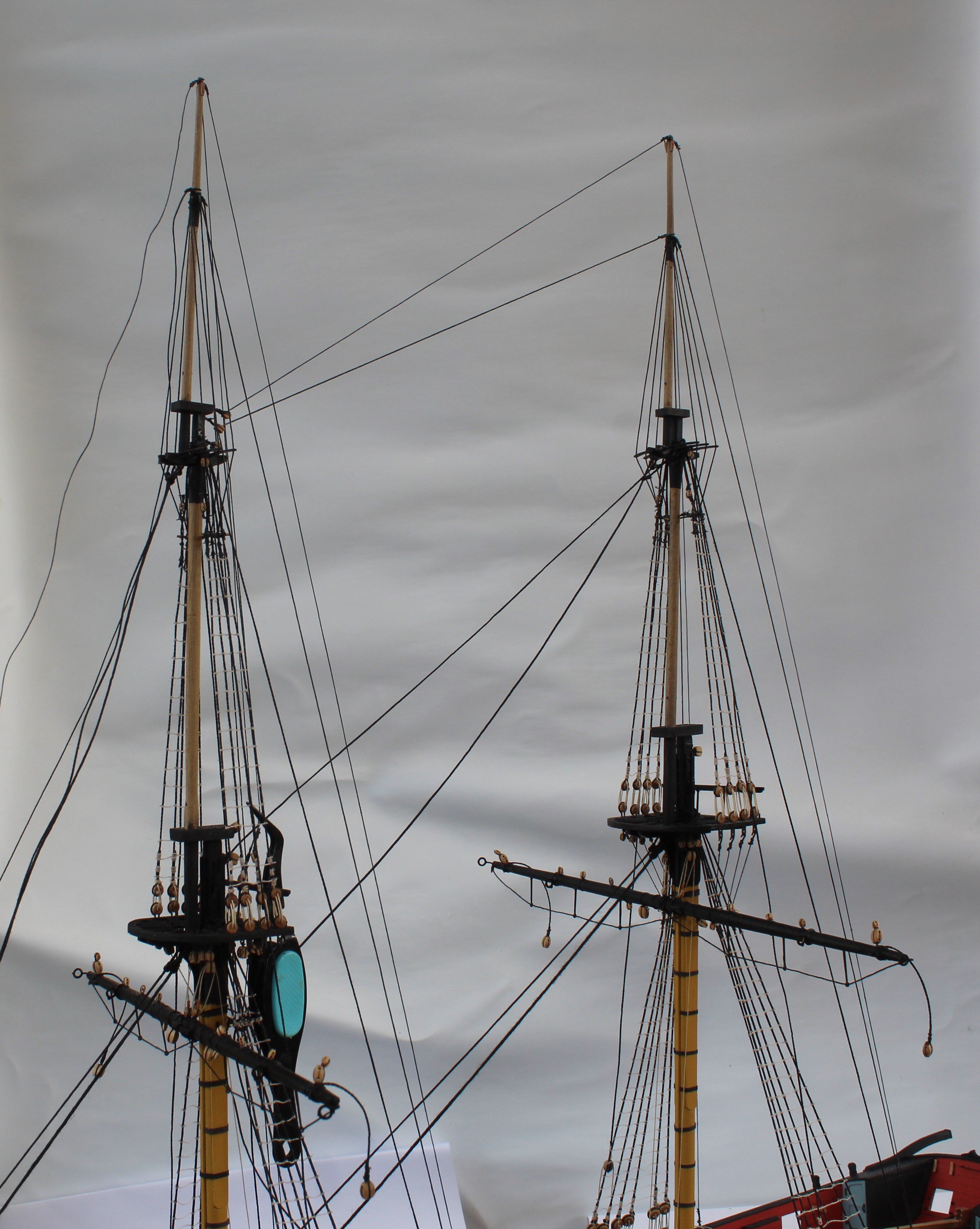
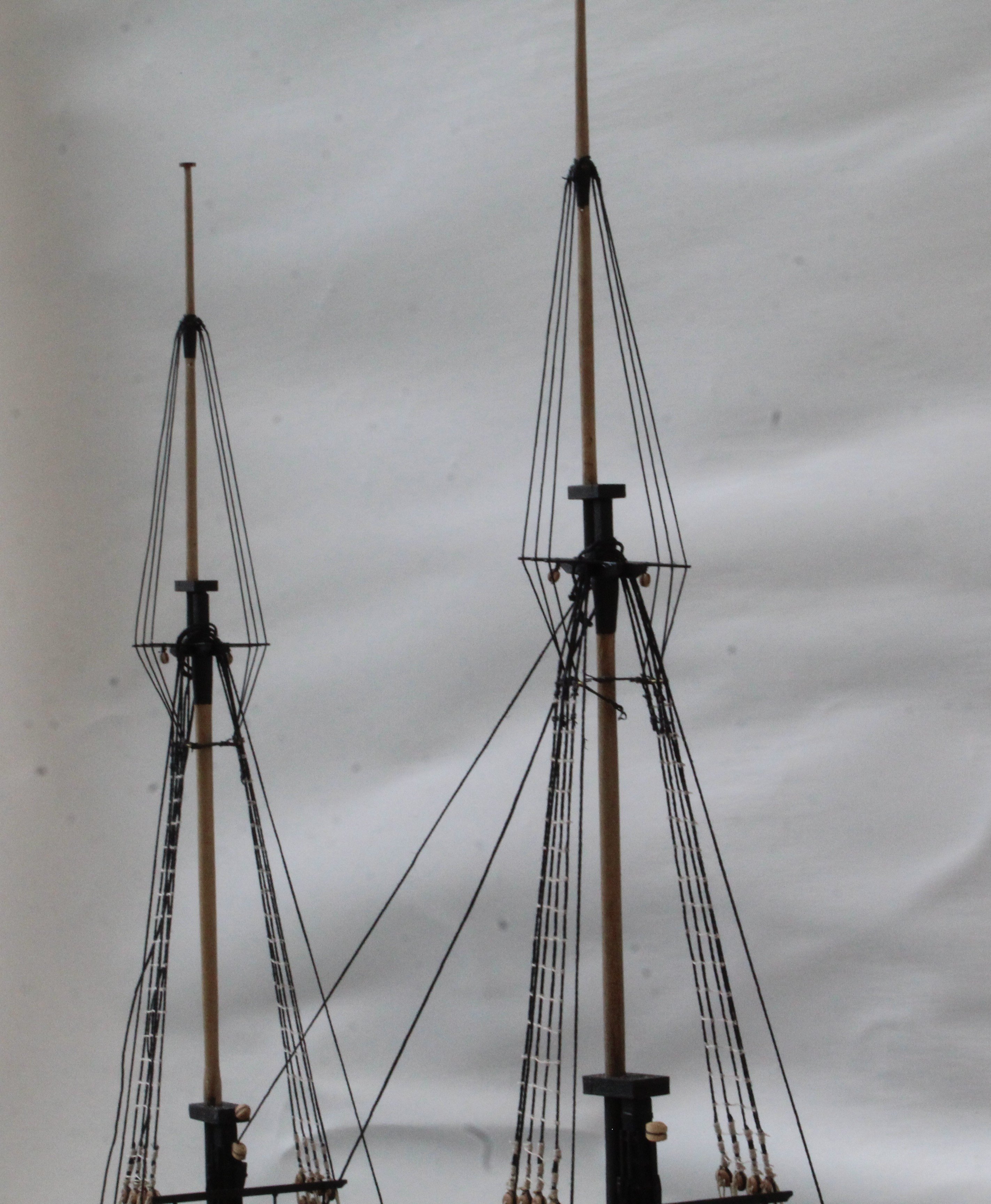
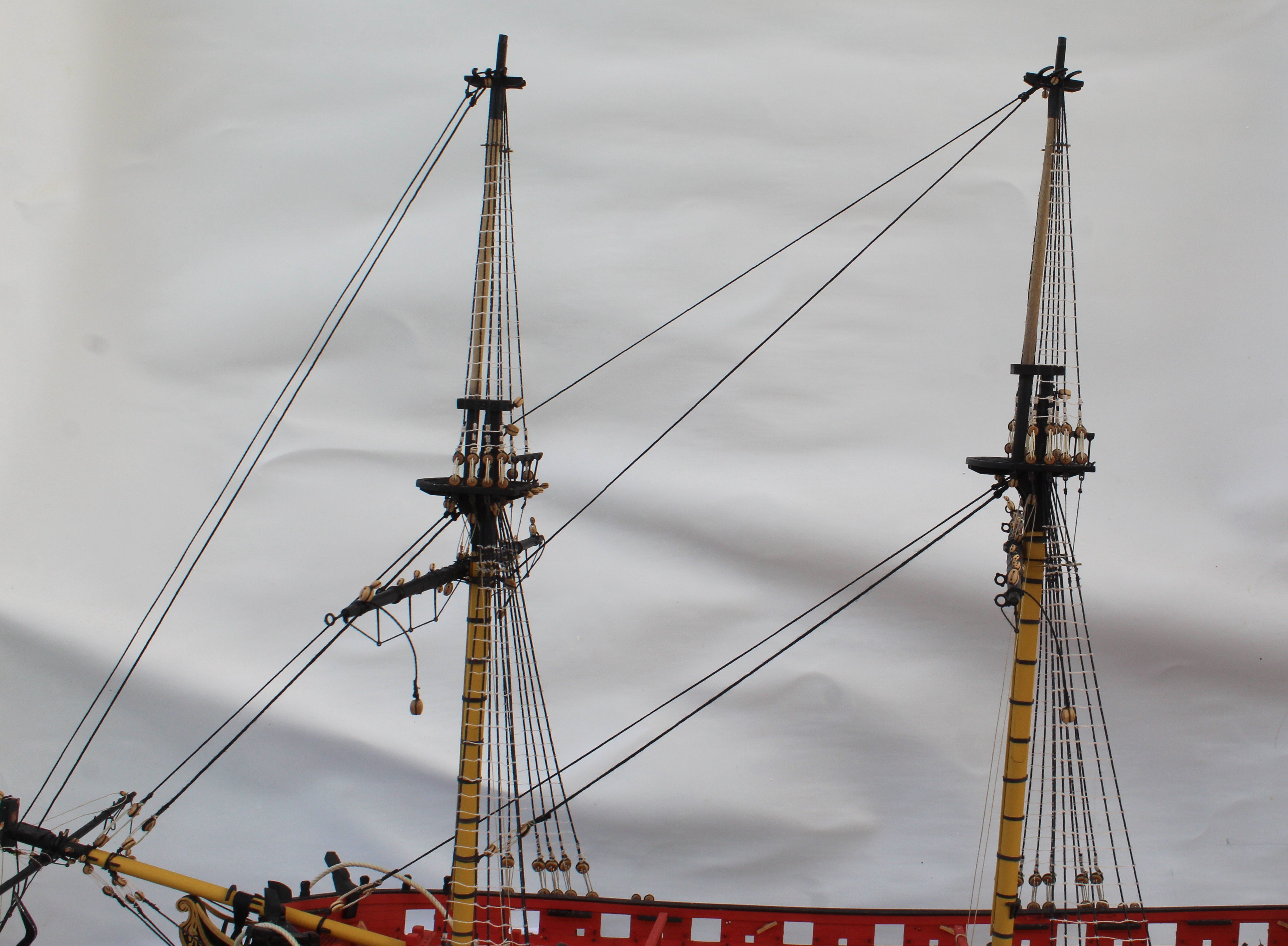
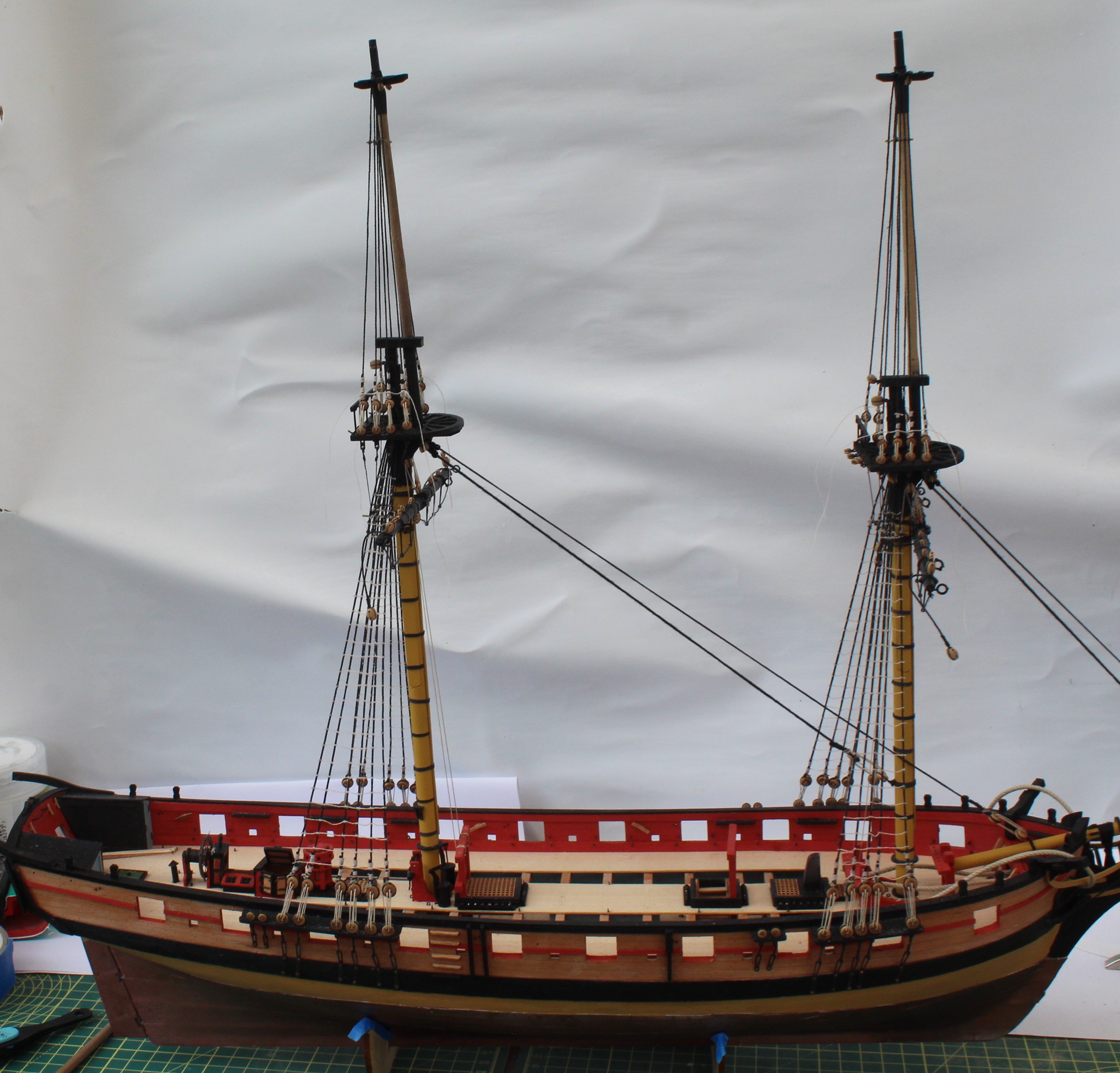
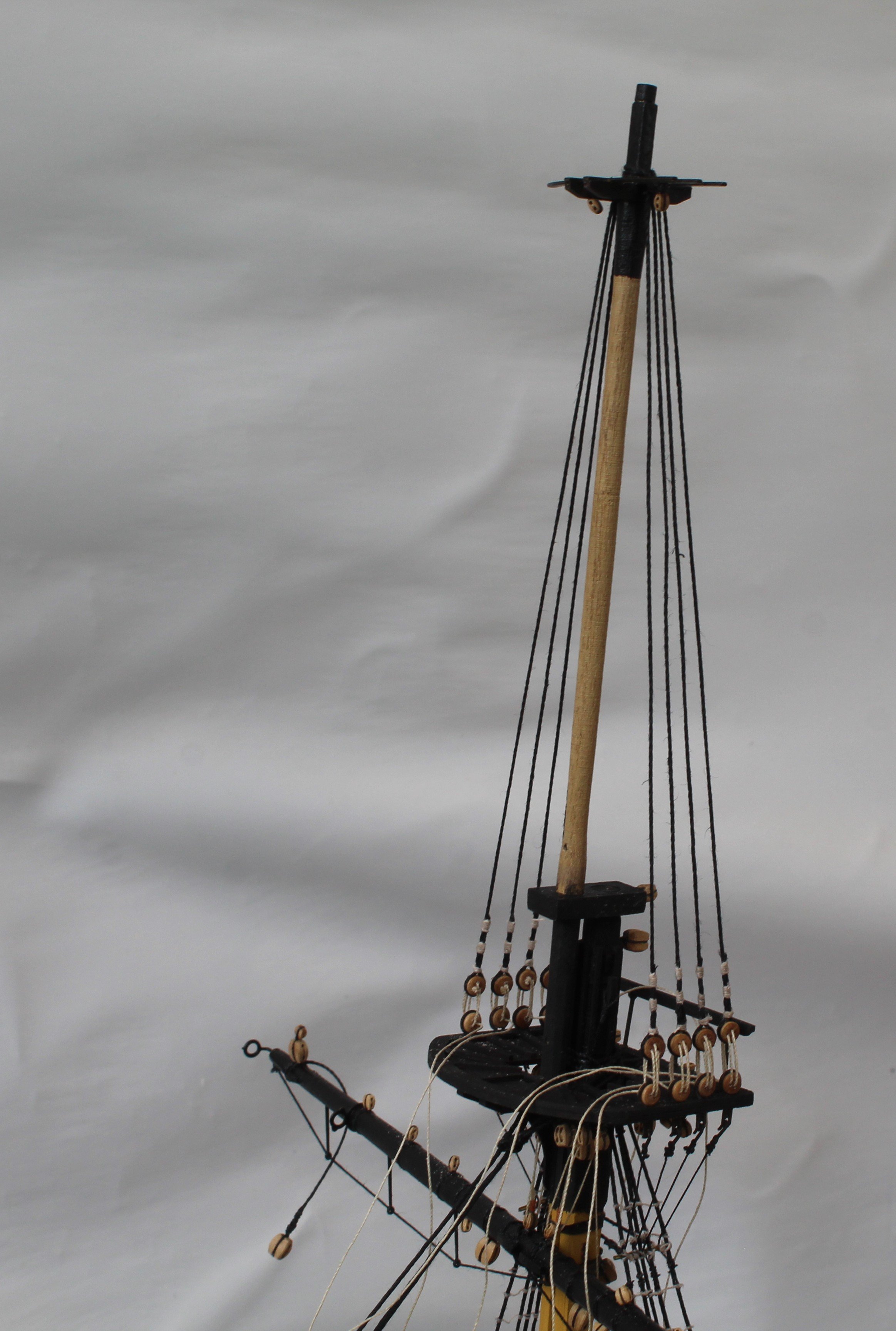
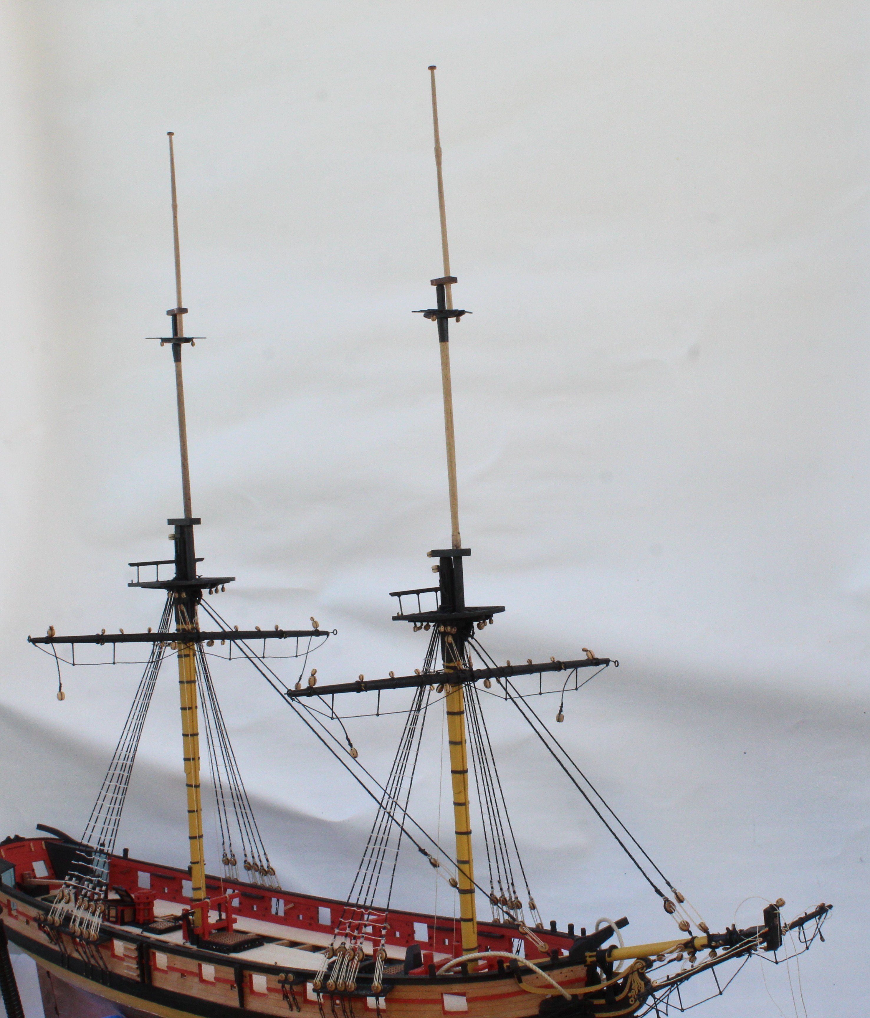
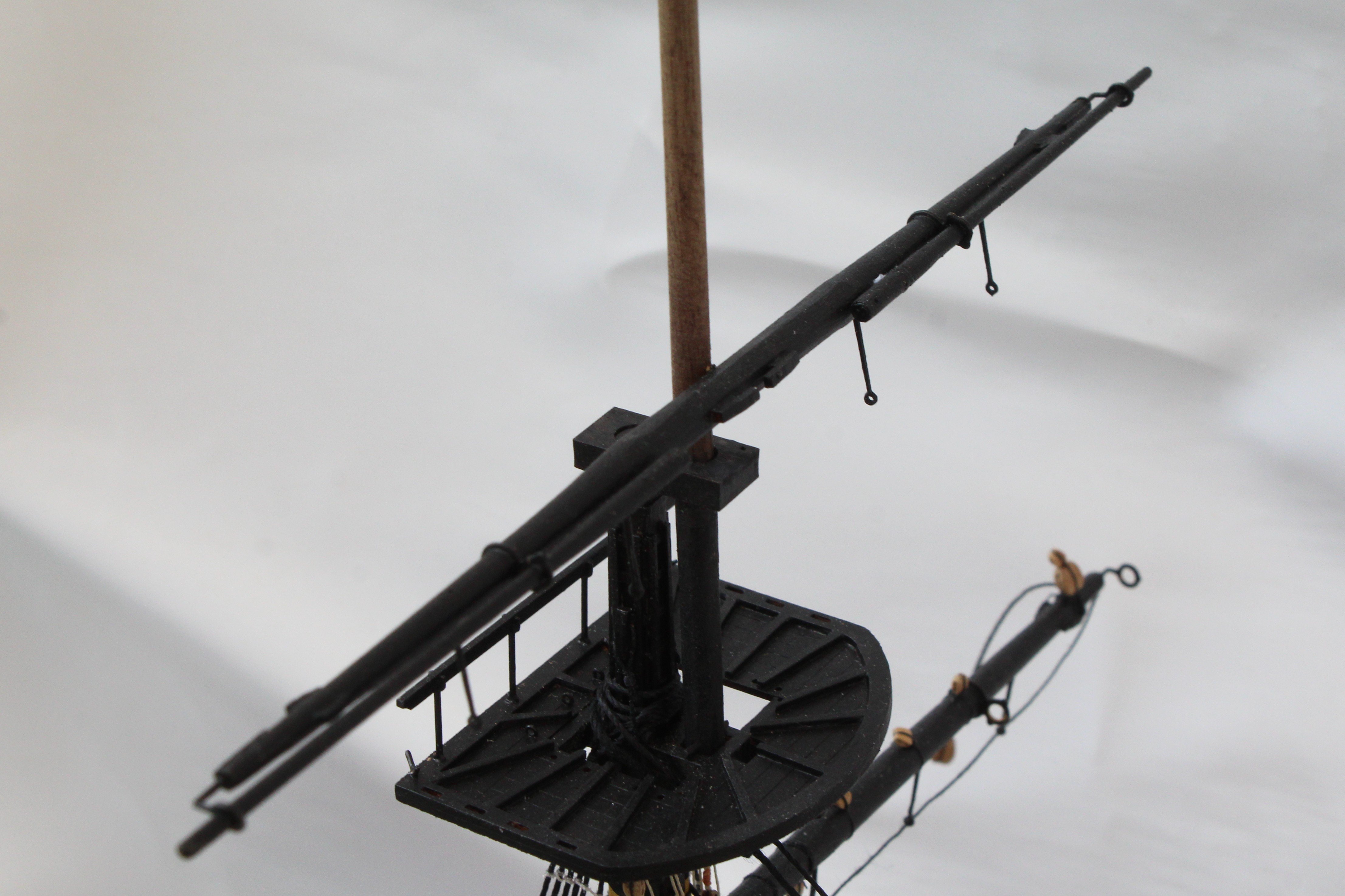
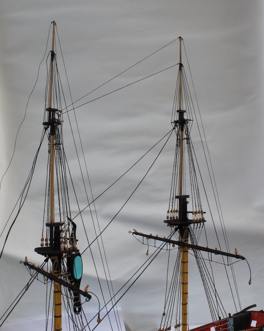
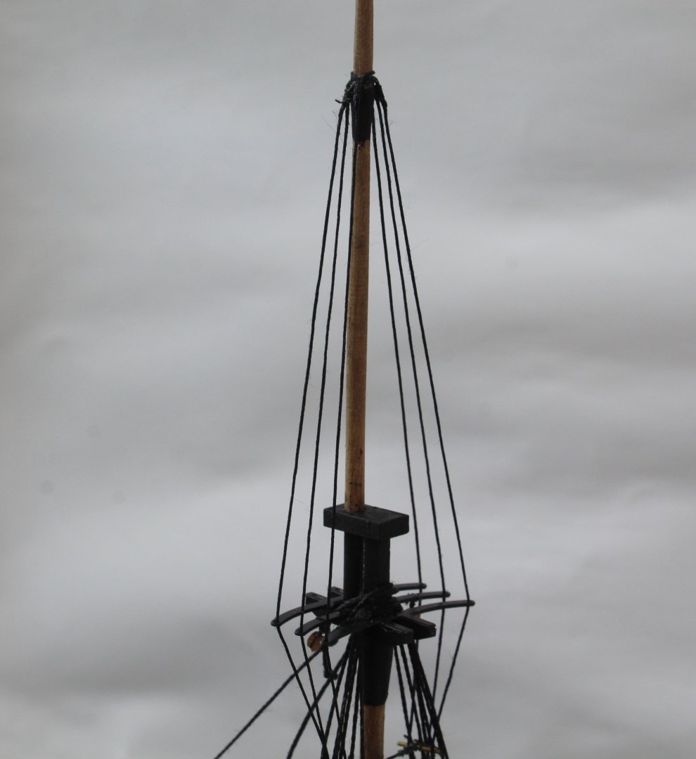
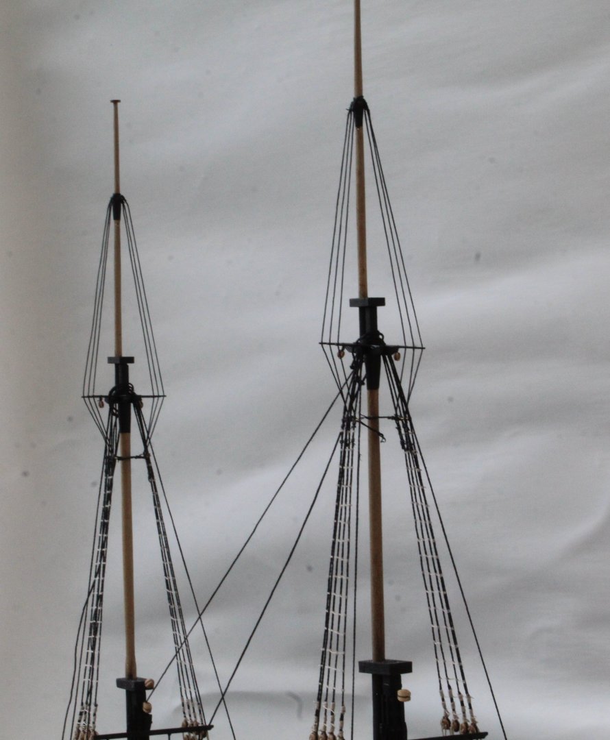
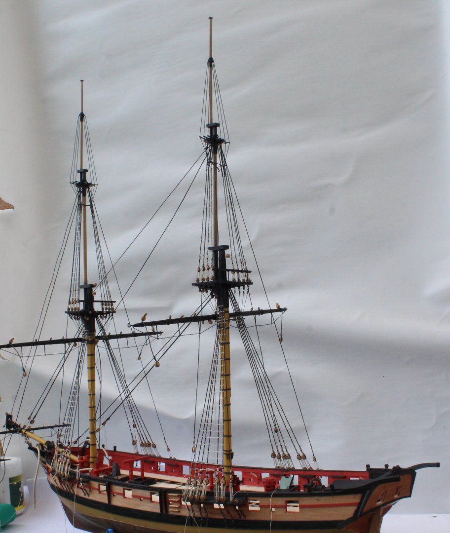
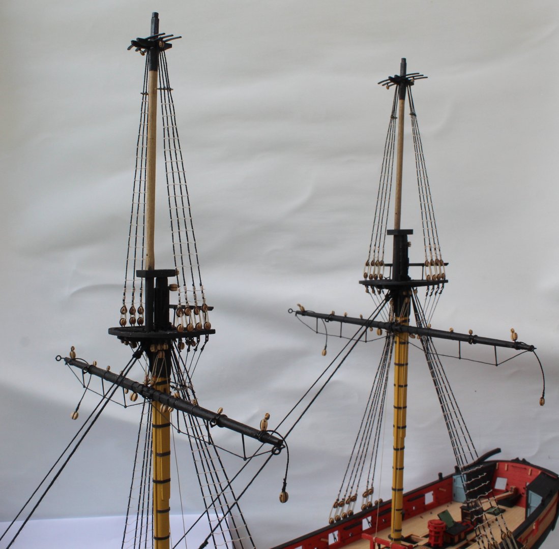
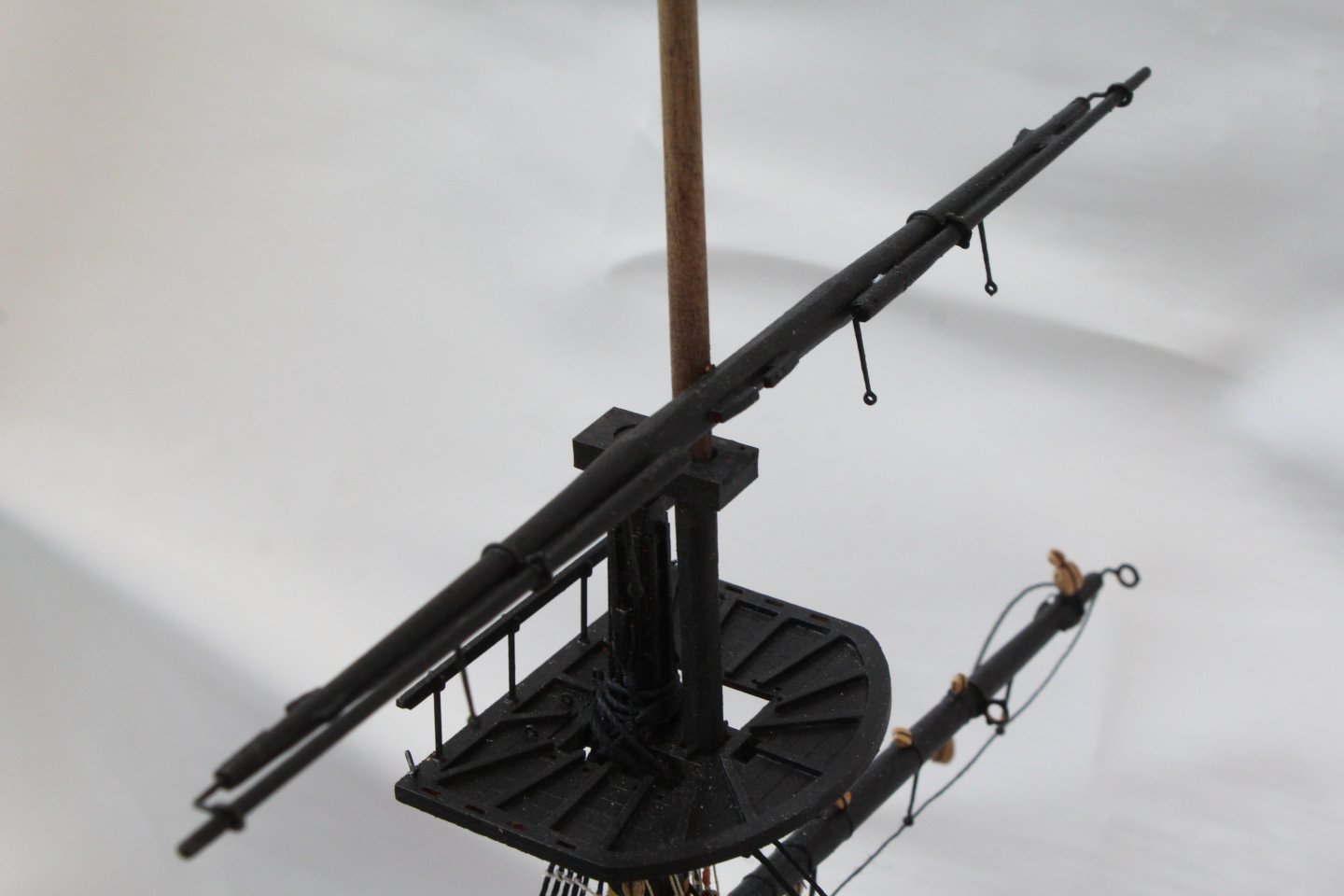
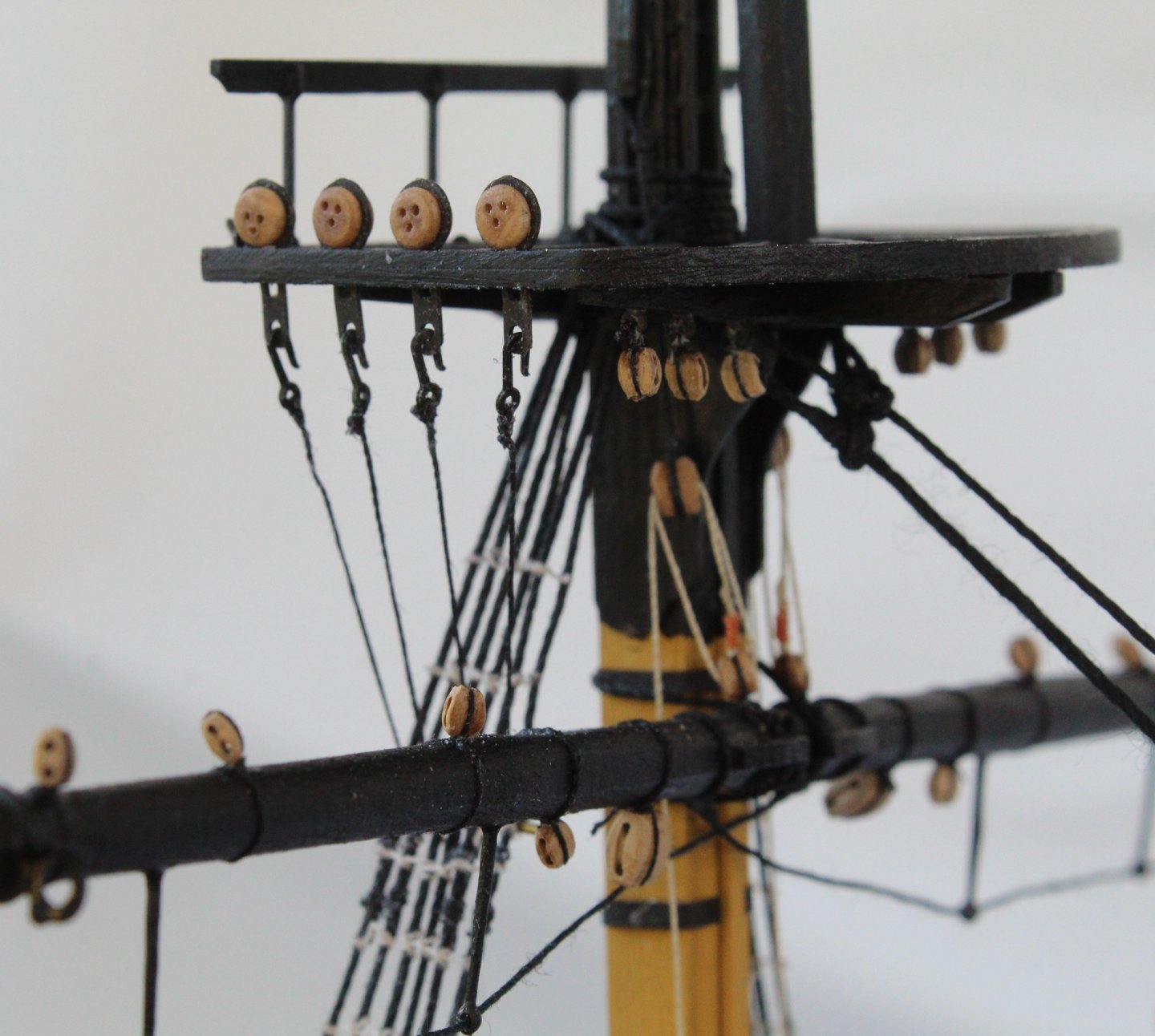
After a weekend away looking after some of our grandchildren I have now been able to spend a little bit of time in the shipyard. The main and fore topsail masts and associated platforms were painted as shown in the plan sheets and then test fitted, as shown below. I then did a quick test fit of the main and fore topgallant masts. Next I did a test fit of the main and fore topsail yards. I am happy with how they look. They will now be removed and will fitted at a later stage in the rigging process. My next task, I thought, would be to add the topsail shrouds. However I then realised I had forgotten to add the futtock stave rigging. This is now currently work in progress and will keep me busy for the next few days. I have added a couple of photos of my progress to date.


- 241 replies
-
- 11
-
-
- Vanguarrd Models
- Harpy
- (and 1 more)
-
Moving on slowly I have now added the bowsprit shrouds and stays. As can be seen in the first set of photos below the lanyards have been run in but not tied off. In the next set of photos the lanyards have been tied off, starting with the main and foremast stays and preventor stays. This is not some of my finest work but I am pleased to have completed this part of the rigging.


- 241 replies
-
- 8
-
-
- Vanguarrd Models
- Harpy
- (and 1 more)
-
I am still basking in the warm sunshine and spending much of my time in the garden and very little time in the shipyard. I have been able to add the main and foremast stays and preventor stays. I am reasonably happy with how they look. I opted to make my own mouse parts rather than using the kit supplied parts. The lanyards have not been tied off as yet.


- 241 replies
-
- 15
-
-

-
- Vanguarrd Models
- Harpy
- (and 1 more)
-
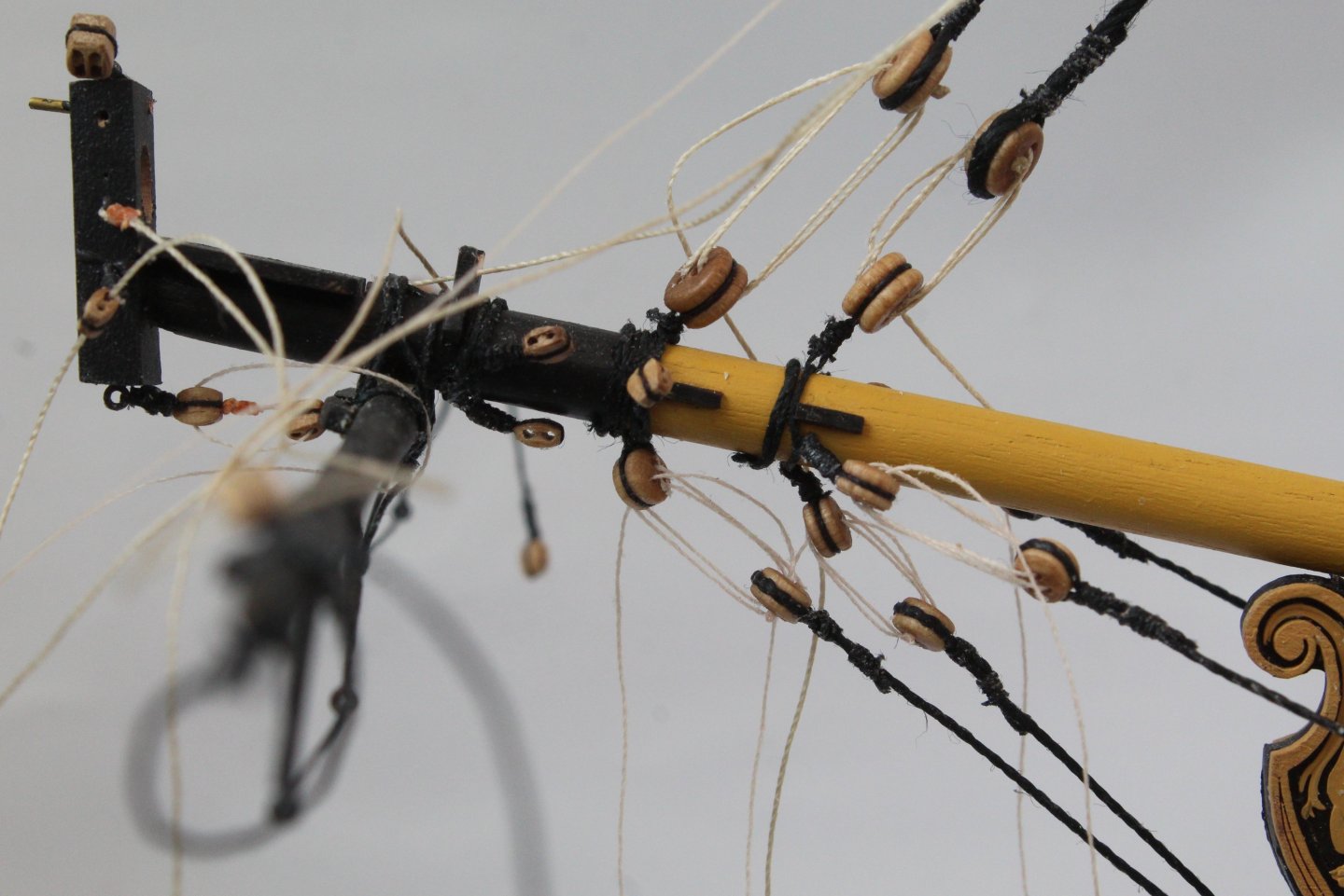
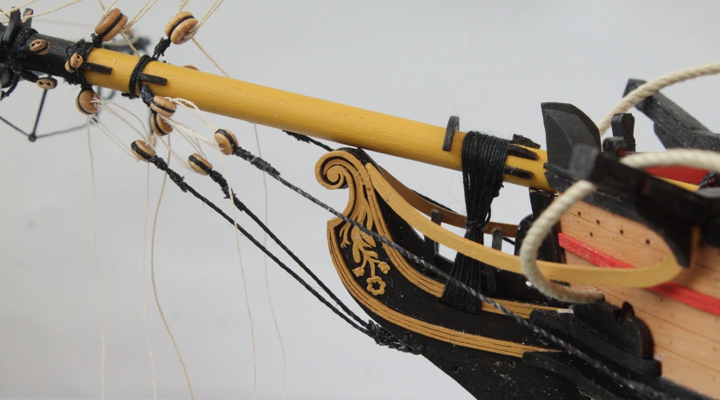
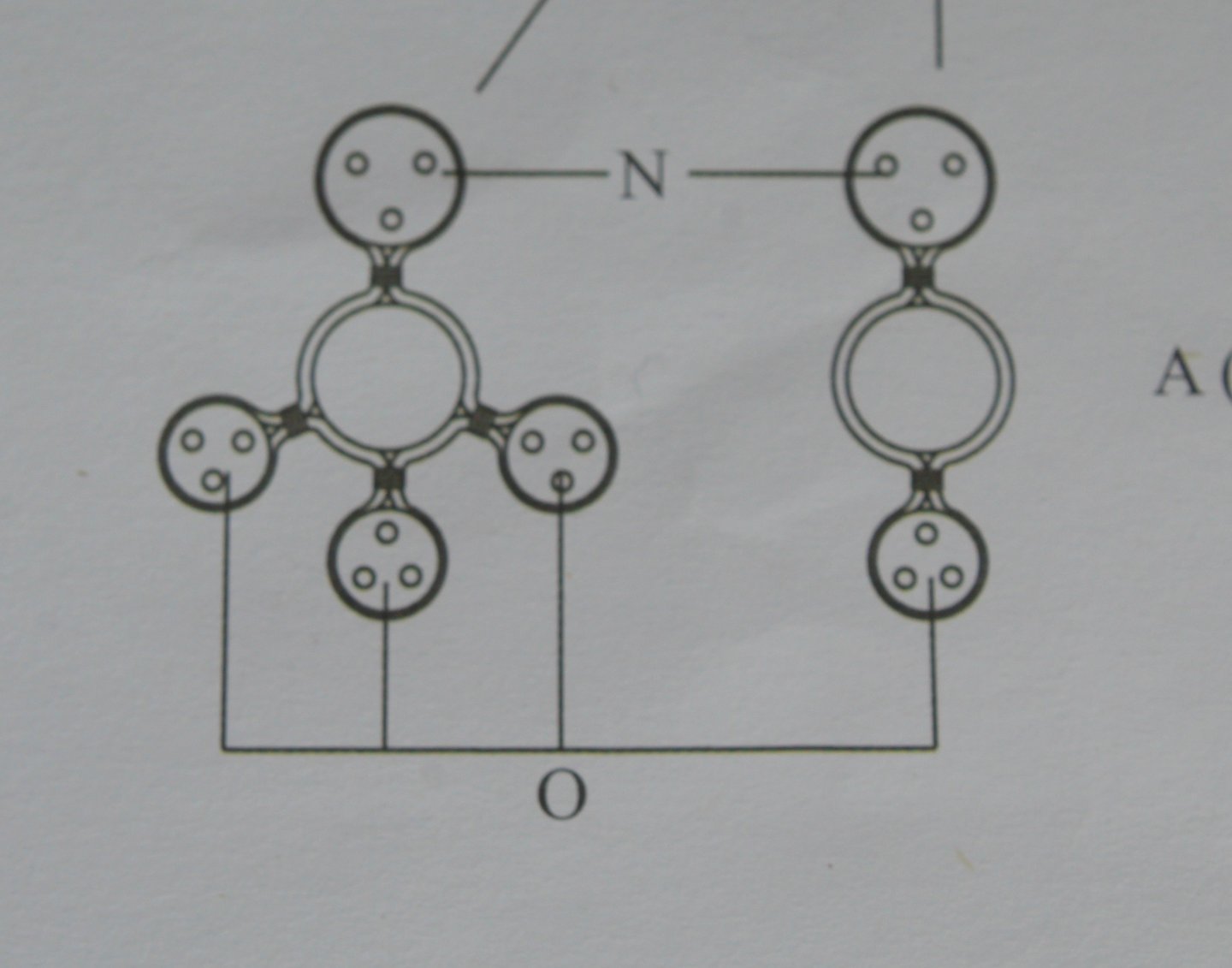
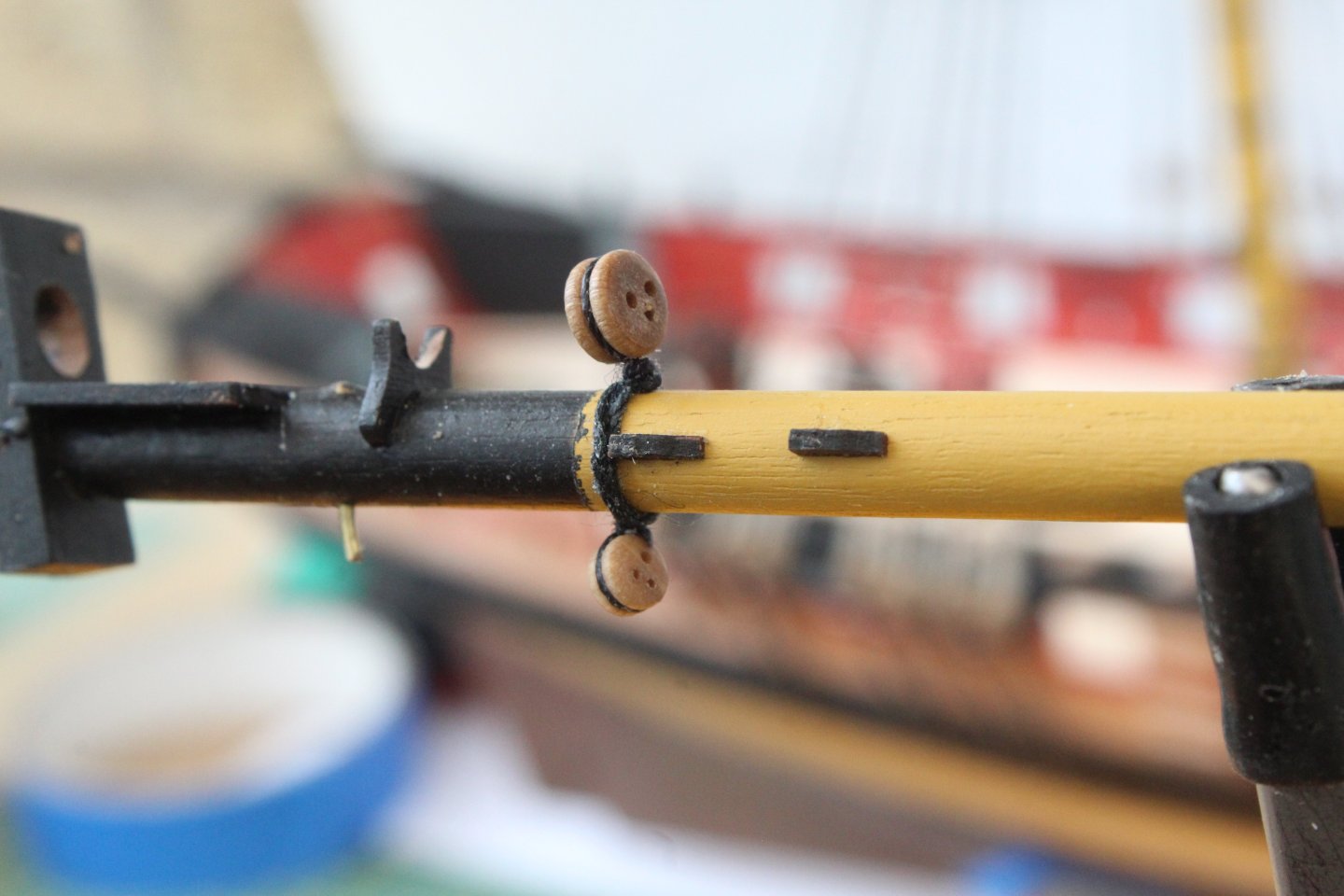
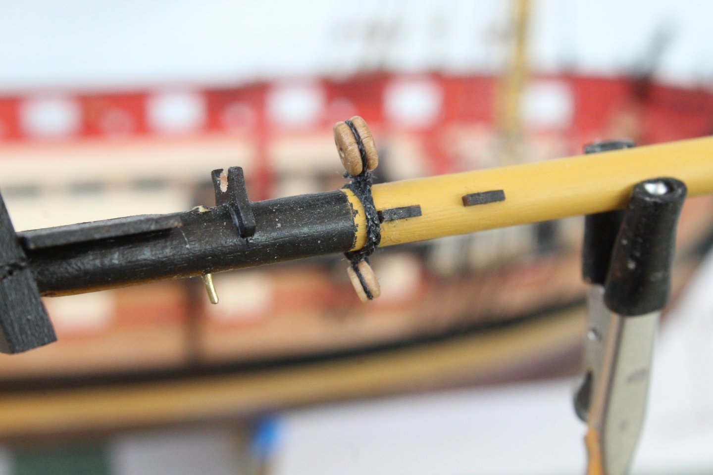
Work has continued on the bowsprit. As can be seen in the photo below I have added all the deadeyes and blocks, using the method detailed in my previous post. I then decided to add the spritsail yard prior to installation of the bowsprit to the Harpy. The spritsail lifts have been rigged and will be belayed once the bowsprit has been installed. The bow sprit was then installed. Next it was time to add the gammoning. To do this a thimble needs to be added to one end of the gammoning thread. As can be seen in the next set of photos this is an easy task, using the quad hands. The next set of photos shows various stages of adding the gammoning, including the tying off. Please note I did redo the start as the way I used the thimble in the first photo below was not right.


- 241 replies
-
- 11
-
-
- Vanguarrd Models
- Harpy
- (and 1 more)
-
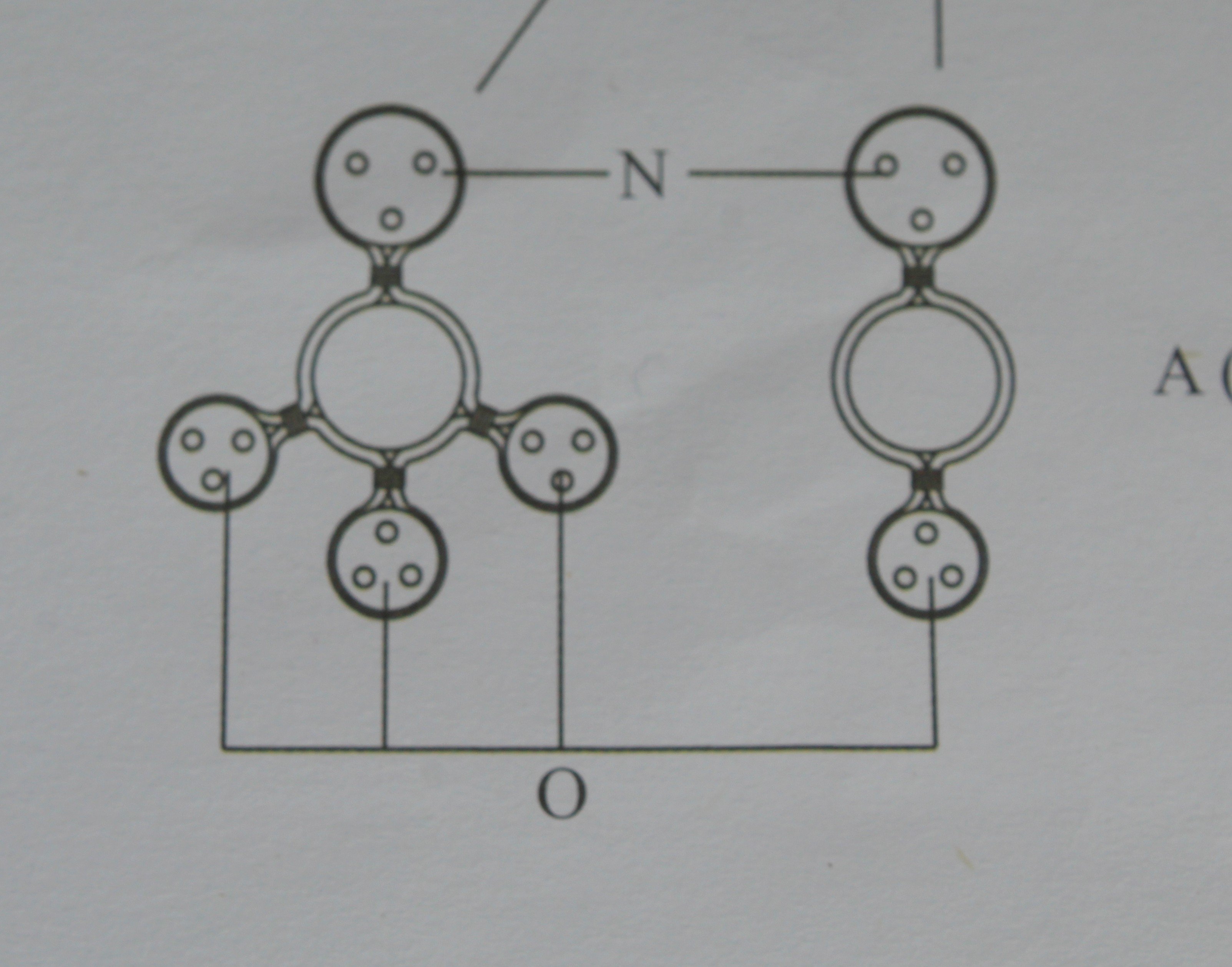
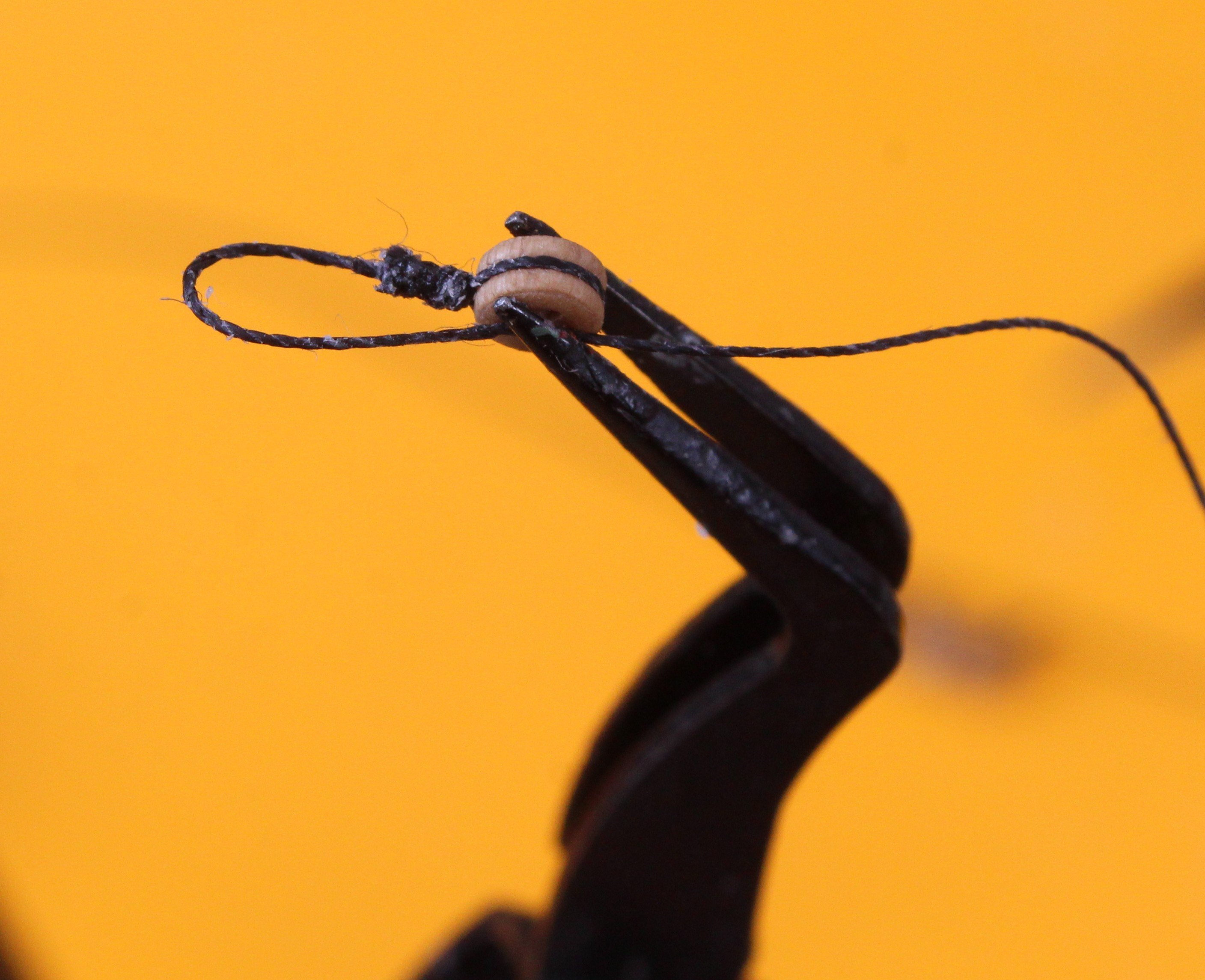
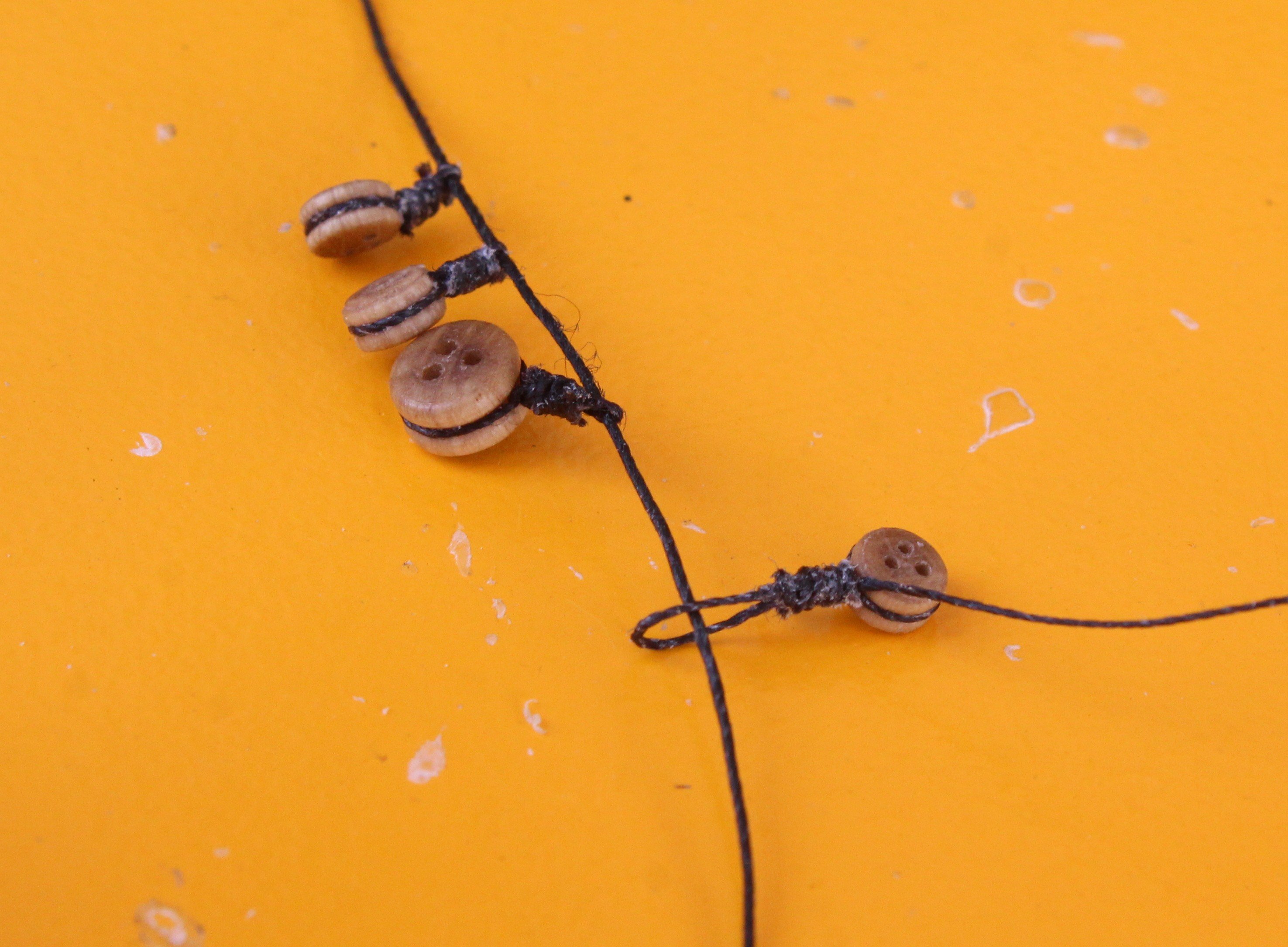
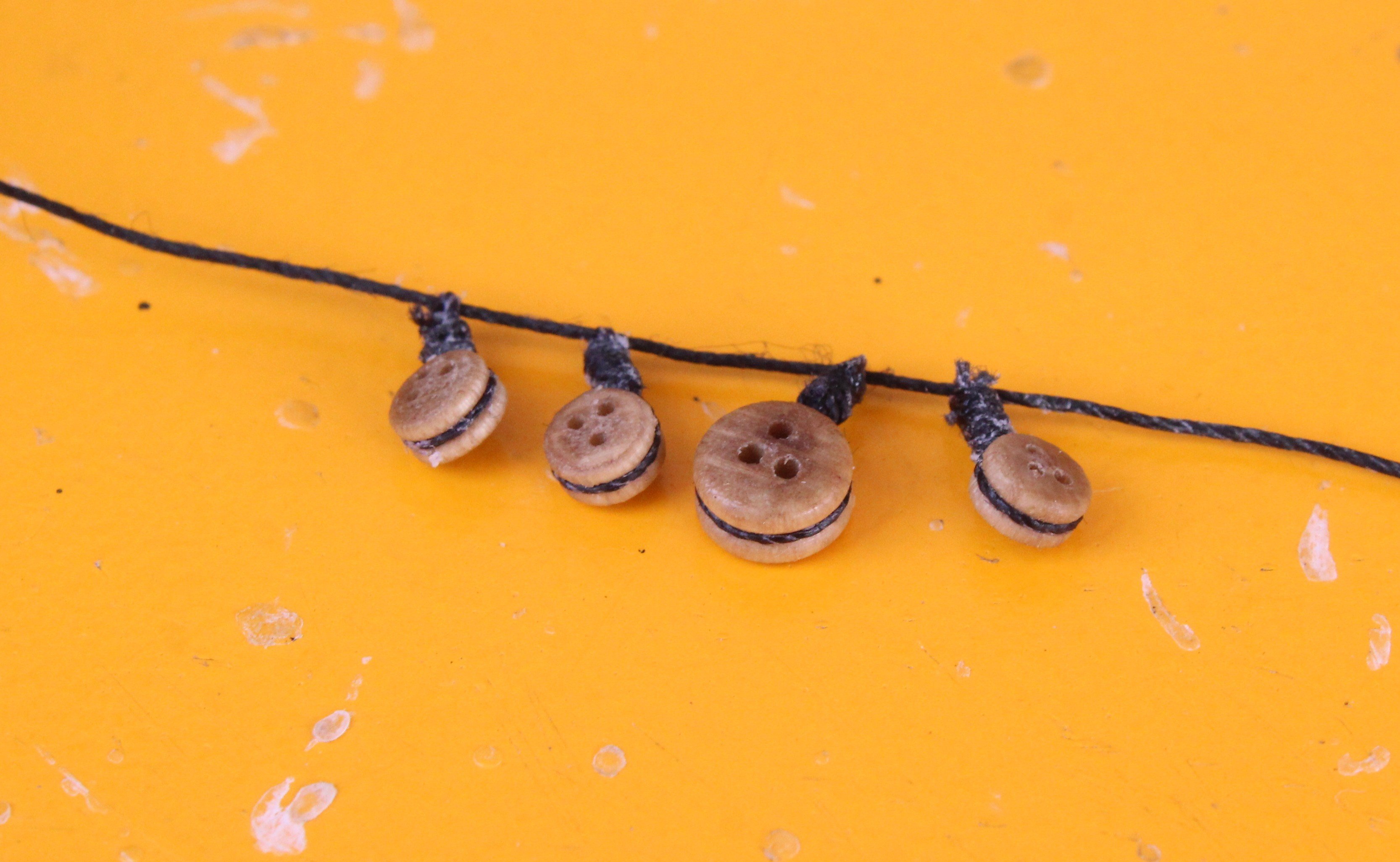
Due to the heat wave we are currently enjoying in the UK my time is the shipyard has been severely limited as I have spent much more time in the garden. When grabbing a bit of time in the shipyard I have been working on adding the various blocks and deadeyes to the bowsprit and spritsail yard. The attached plan shows the requirement with regards to the deadeye rings. I thought I would share the process I am using for adding the 4 x deadeye rings. I start by looping a length of thread around the deadeye and securing with a reef knot. The deadeye is then placed in the quad hands so the seizing can be added. In the next photo I have added the seizing to the deadeye. Next I create a loop with one end of the thread, noting the other thread end has been cut away. This is then held in the quad hands so the loop can be seized. Once the loop has been seized the loop is threaded on to another length of thread, as shown below. The loop can the be closed up by pulling the free end of thread, and the excess thread is then cut away. With all four deadeyes in place the thread can be secured to the bowsprit. The position of deadeyes can then be adjusted, as necessary.


- 241 replies
-
- 13
-
-
- Vanguarrd Models
- Harpy
- (and 1 more)
-
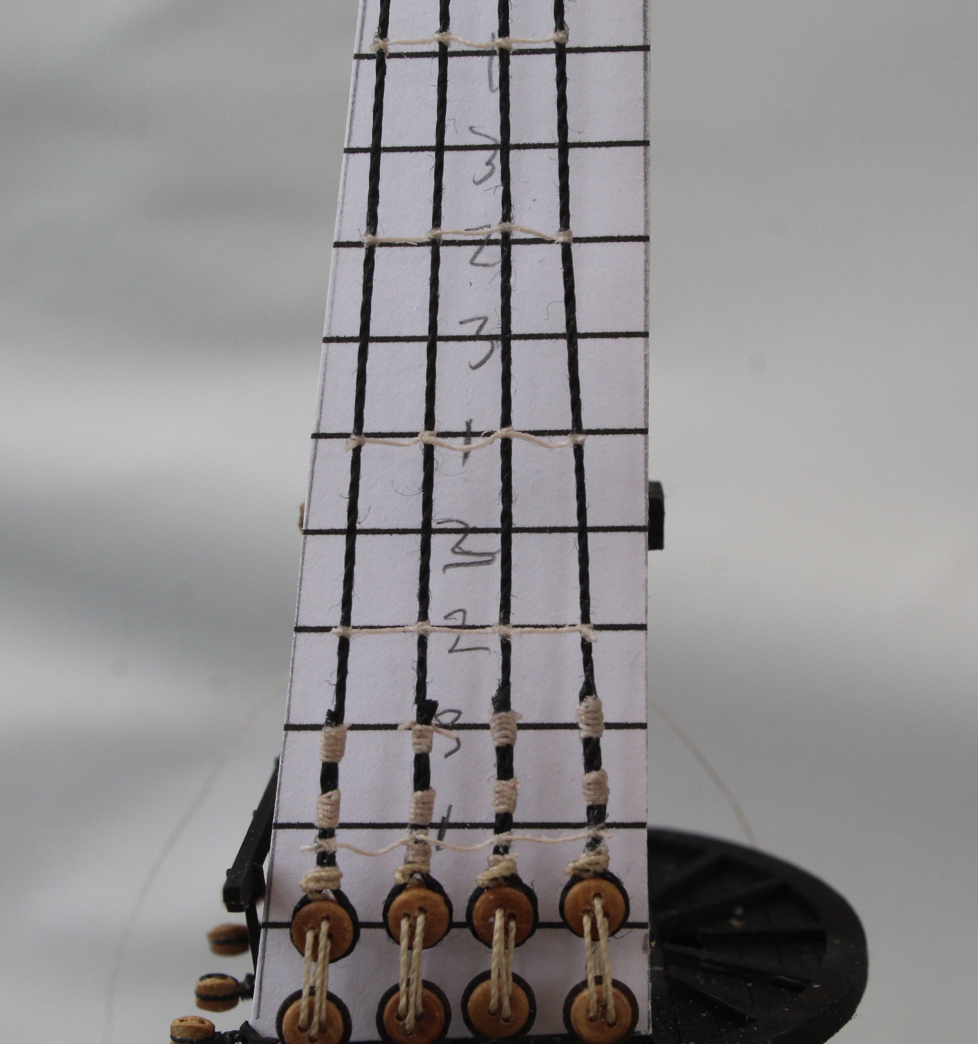
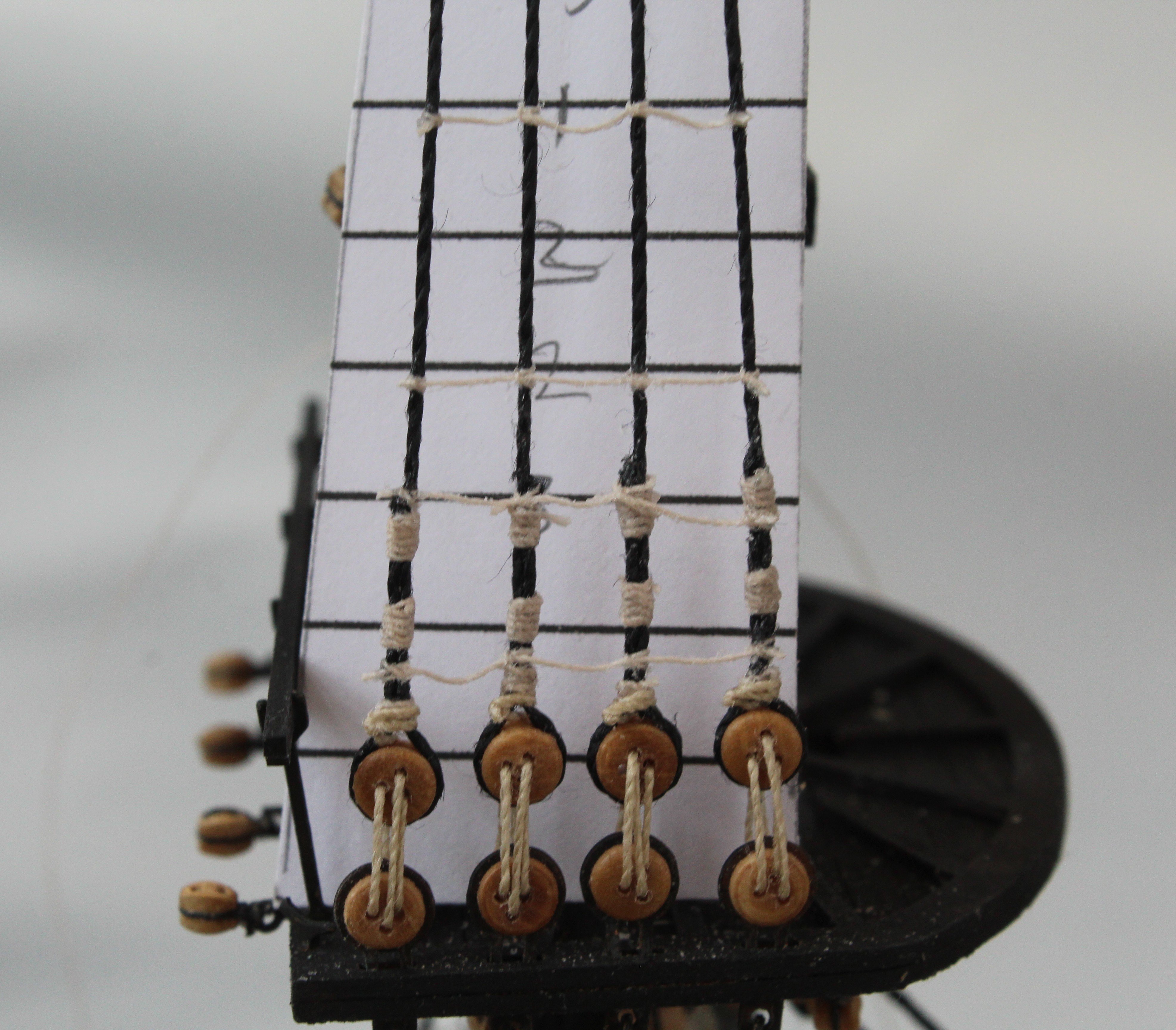
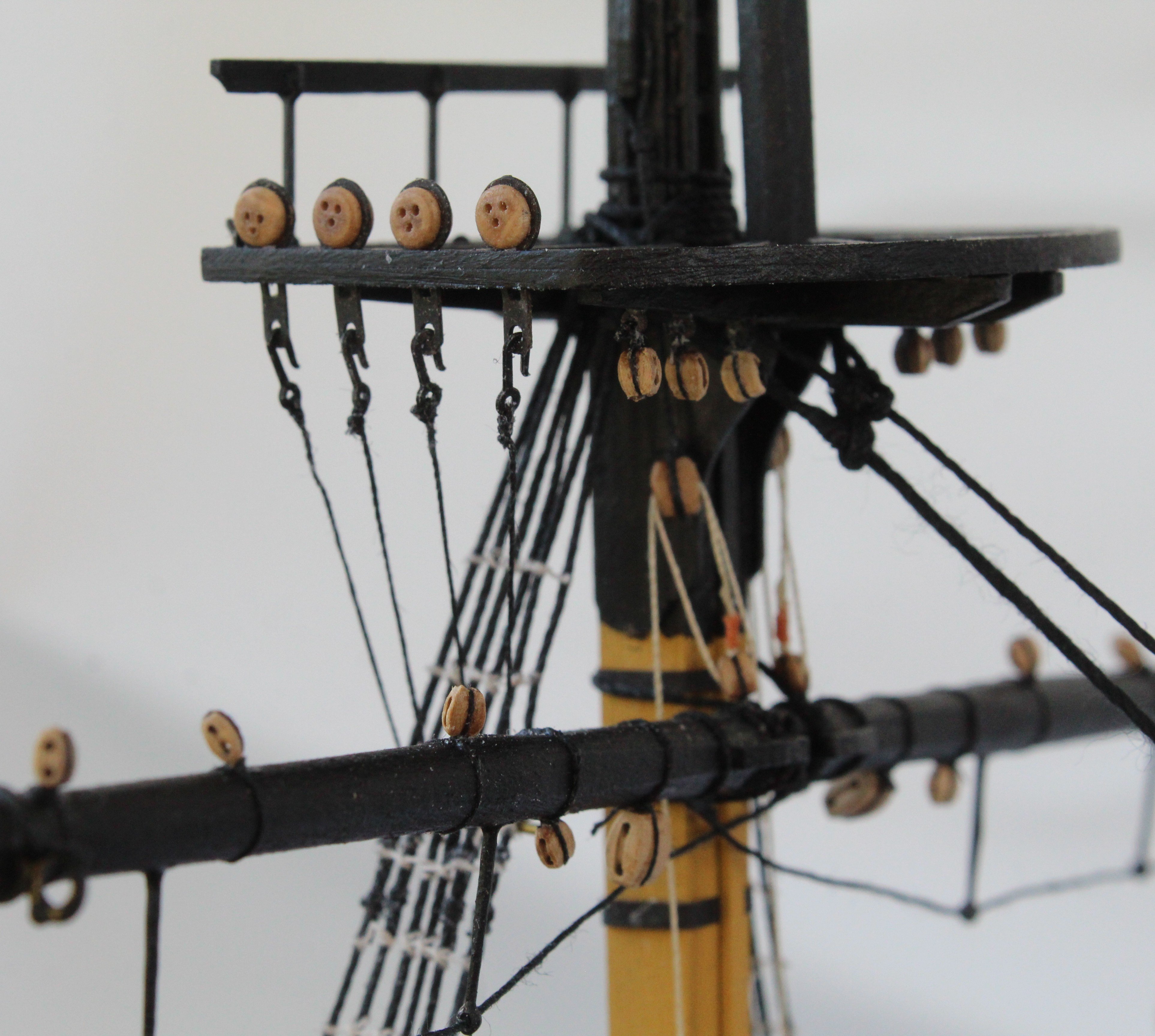
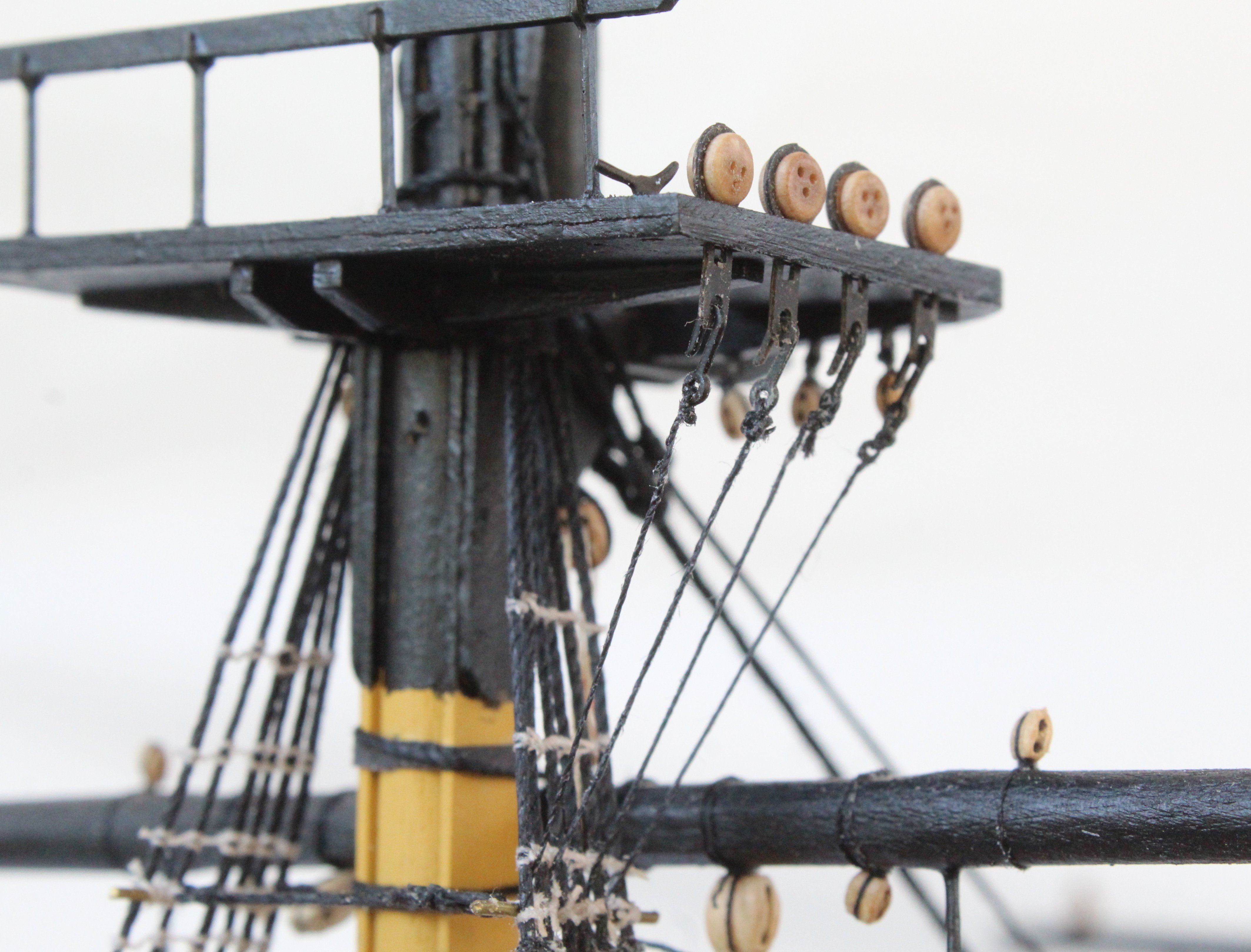
Work is progressing slowly but steadily on adding the main mast ratlines. Whilst I did like the idea of adding the yard to the mast prior to this task as it made the rigging the jeers much easier I have found the yard, when in situ, does hinder adding the upper few rows of ratlines. I started the process by adding the futtock staves, using a template to set the height equally on both sides. The copper bar was held in place using my quad hands whilst it was secured to the shroud lines. Once that was done it was simply a case of adding the ratlines. As per my earlier post I prefer to add every 5th one initially and then everyone central one between the first set of ratlines before adding the final set. I finds this method works as it prevents the hourglass effect. Also it helps to prevent having to many sagging ratlines. As can be seen in the photo below they are not perfect and I do need to adjust a couple of them but I am reasonably happy with the end result. In the next photo I have added the first two sets of ratlines on the other side and I have just started to add the final set of ratlines. I tend to leave the lowest ratlines until the end. I did record a video of adding a set of ratlines, which uploaded to YouTube YouTube Video Link If you look at the video please note that a) It was very difficult to set up the camera to record this process, in this instance the camera need to be pointed upward a bit more. b) I started by passing the ratine thread through a block of beeswax, but this bit is out of focus c) I then make a series of clove hotch knots, as each clove hitch knot is made I check it position with the template and adjust as necessary d) I am also checking the vertical alignment of the shroud lines with the marked lines on the template.

- 241 replies
-
- 9
-
-
- Vanguarrd Models
- Harpy
- (and 1 more)
-
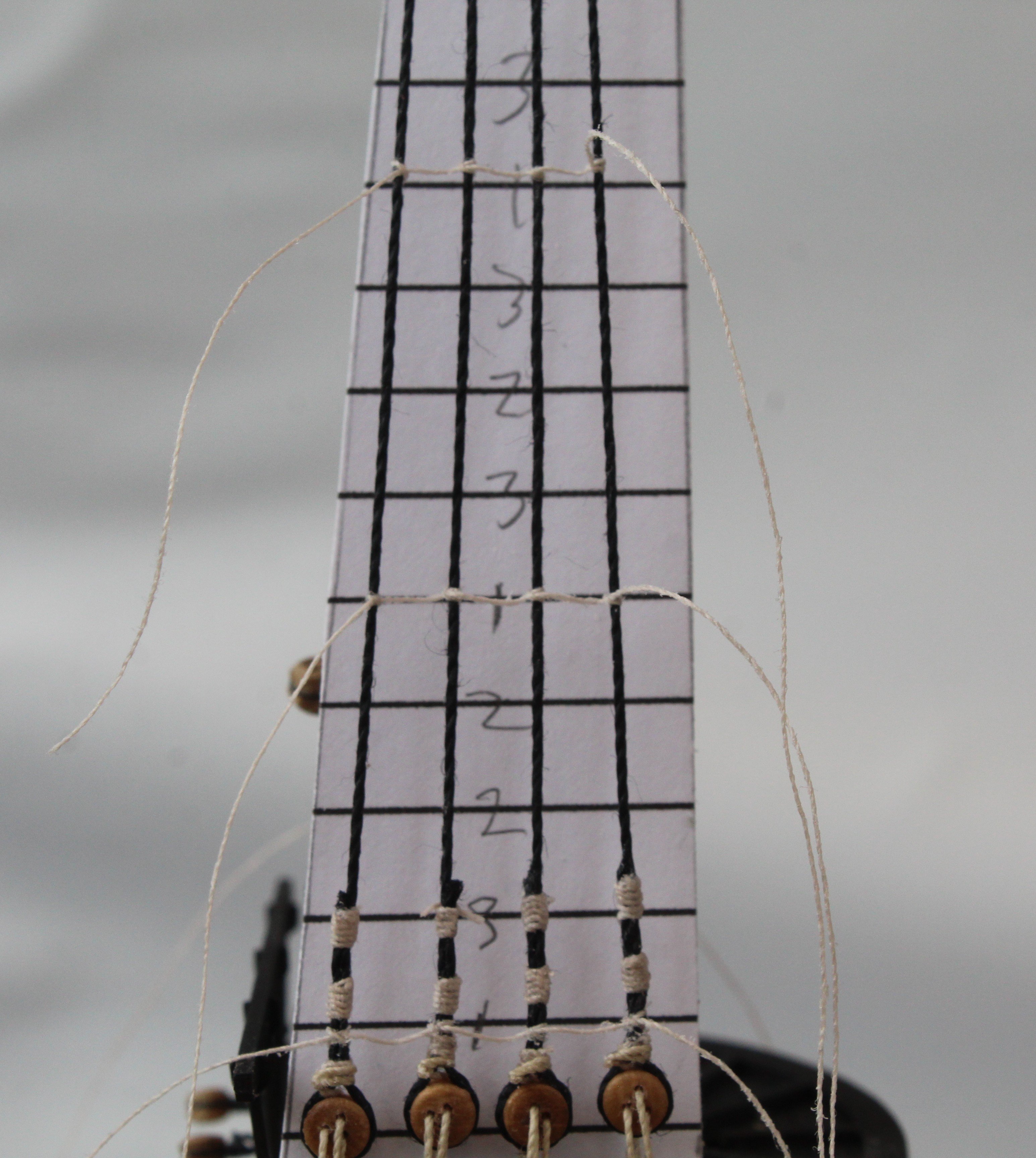
Hi Ross If you look at my previous post you will see how I have marked the ratline template with 1, 2 and 3. I will add all the 1's (every 5th one) first as I have found this helps prevent the dreaded hourglass shroud shape. This is because the vertical slants can be set with just a few ratlines added. Once that is done the infill ratlines can be added Once I haved added all the 1's I will add all the 2's which are spaced evenly between the 1's. Finally I will add all the 3's. As you will note my template has both horizontal and vertical guide lines. However sometimes I do find it necessary to redo some of the ratlines. Hope that answers your question
- 241 replies
-
- 7
-
-
-
- Vanguarrd Models
- Harpy
- (and 1 more)
-
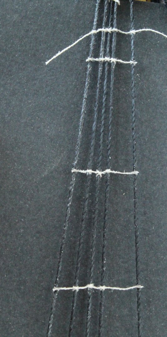
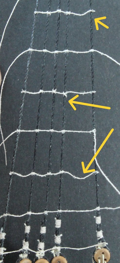
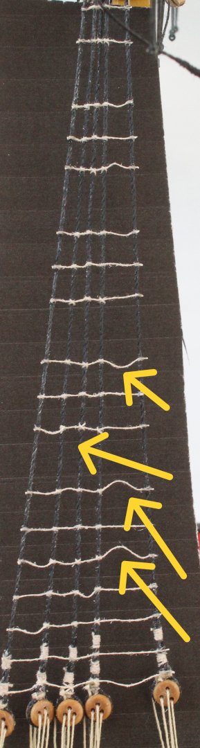
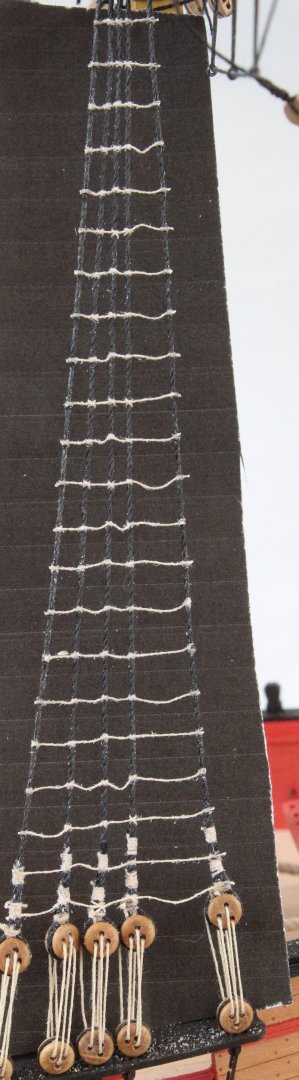
Starting to add the first ratlines, as mentioned in my last post I am adding every 5th one to start with. When I had completed adding every 5th ratline I did then the next ratline above the top 5th ratline. As I started to add the next set of ratlines I noted that I may need to revisit some of the one previously added, as can be seen below. With the next set of ratlines added I am still noting which ones may need to be redone. Moving on to adding the next set, as can be seen below With the ratlines completed I now need to decide which ones do not pass muster and will need to be redone. Reworked some of the ratlines and they look much better, as can be seen in the photo below. Some could still be redone but as far as I am concerned they look OK.


- 241 replies
-
- 7
-
-
- Vanguarrd Models
- Harpy
- (and 1 more)