Glenn-UK
-
Posts
3,175 -
Joined
-
Last visited
Content Type
Profiles
Forums
Gallery
Events
Everything posted by Glenn-UK
-
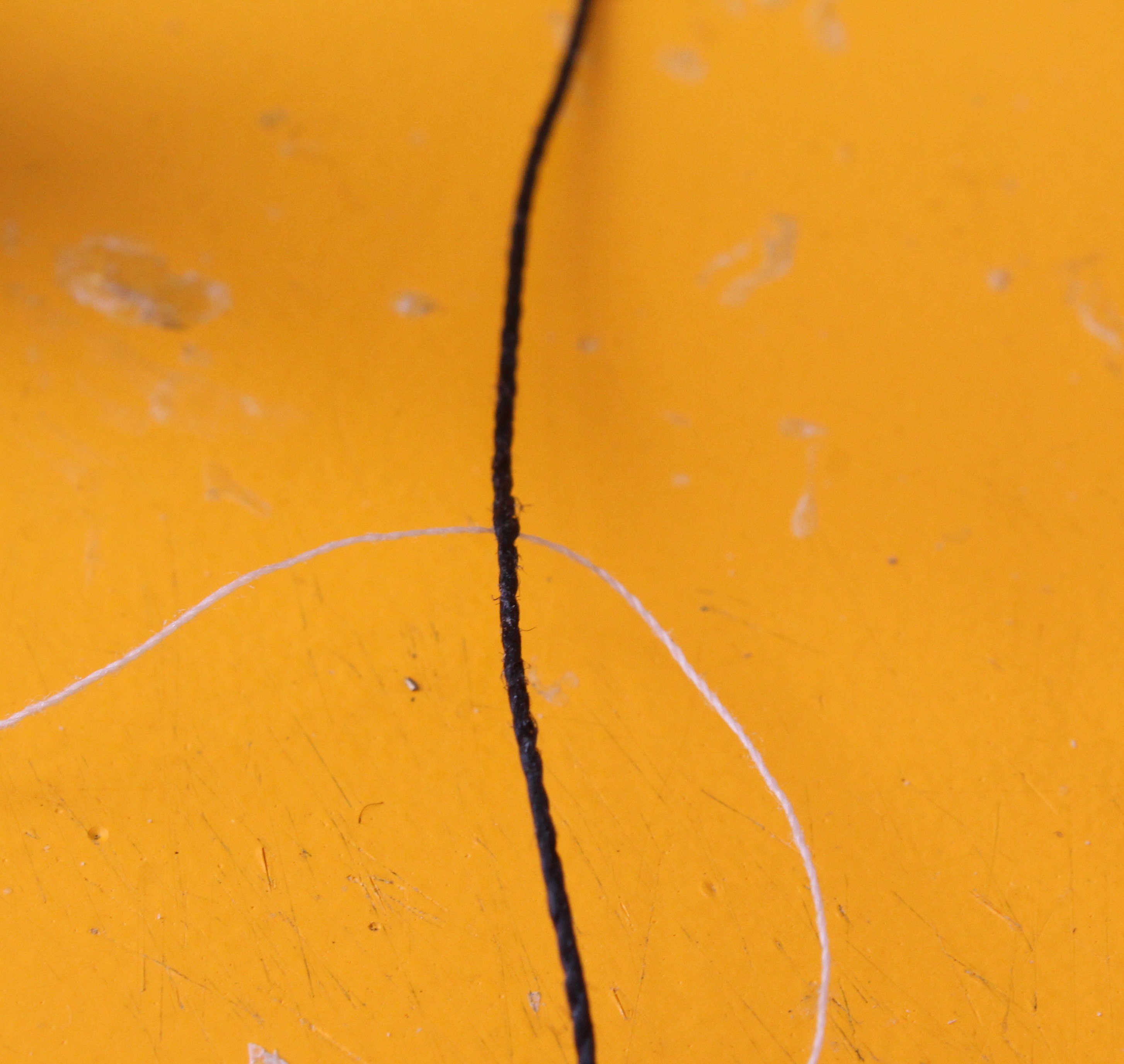
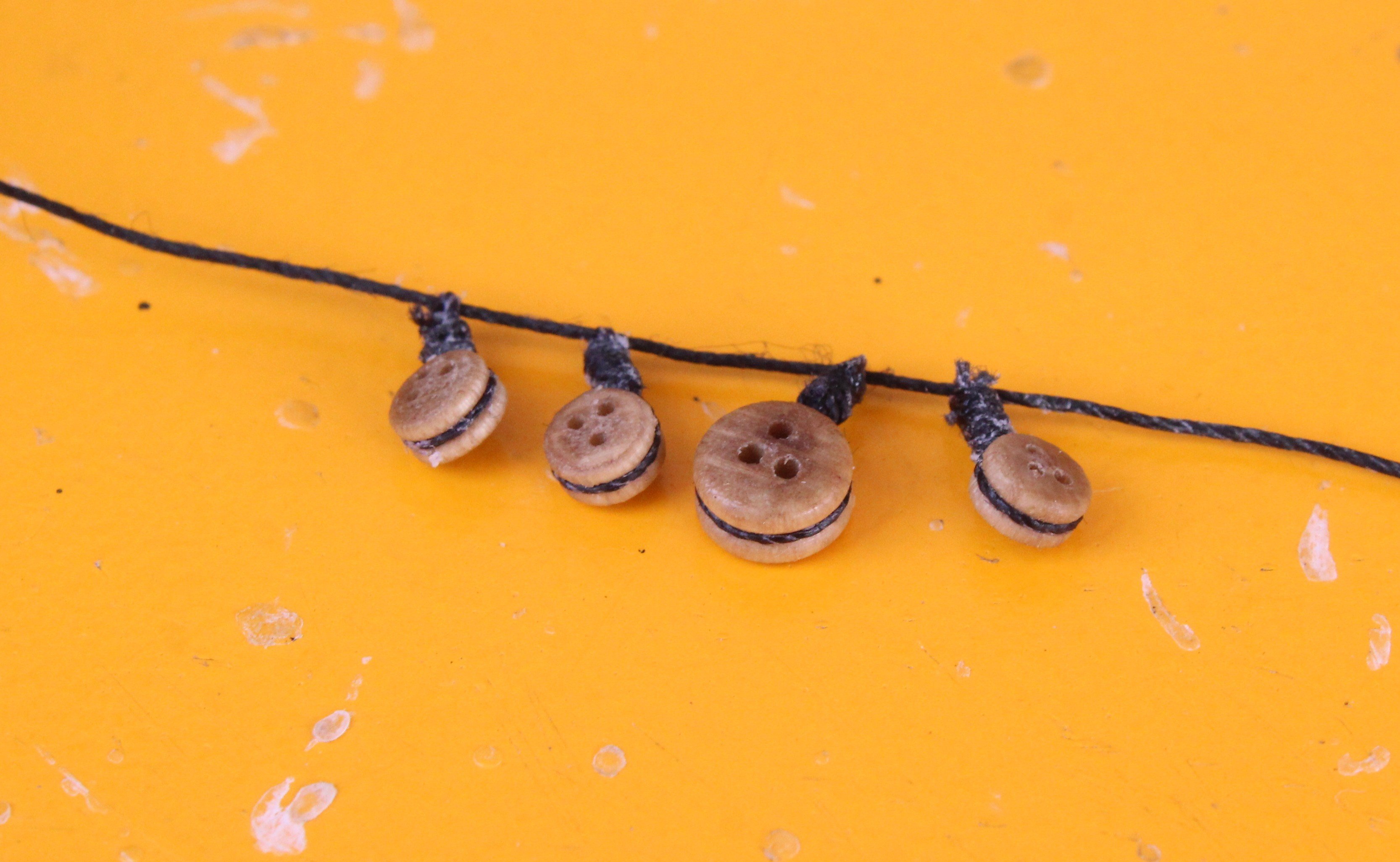
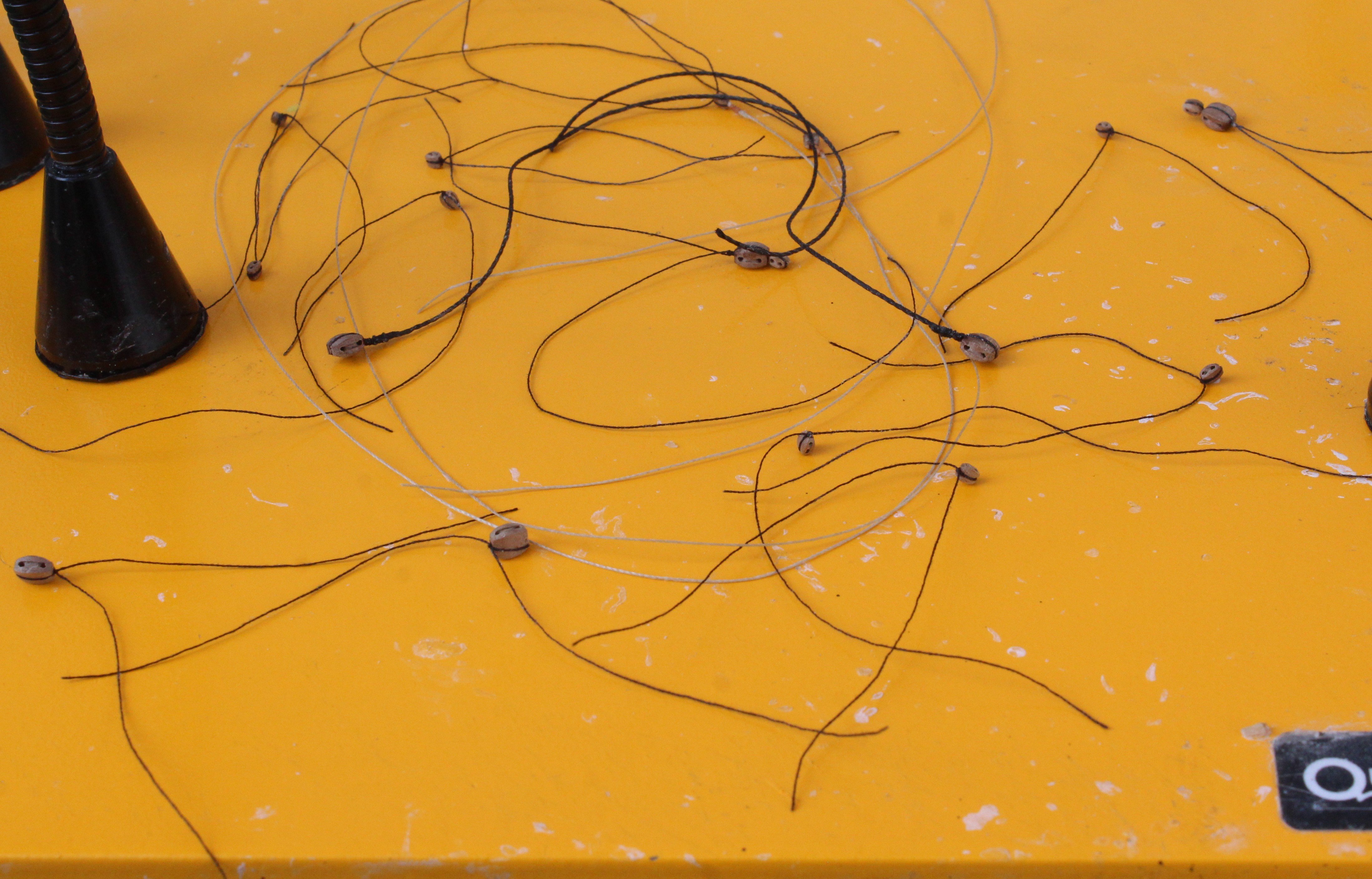
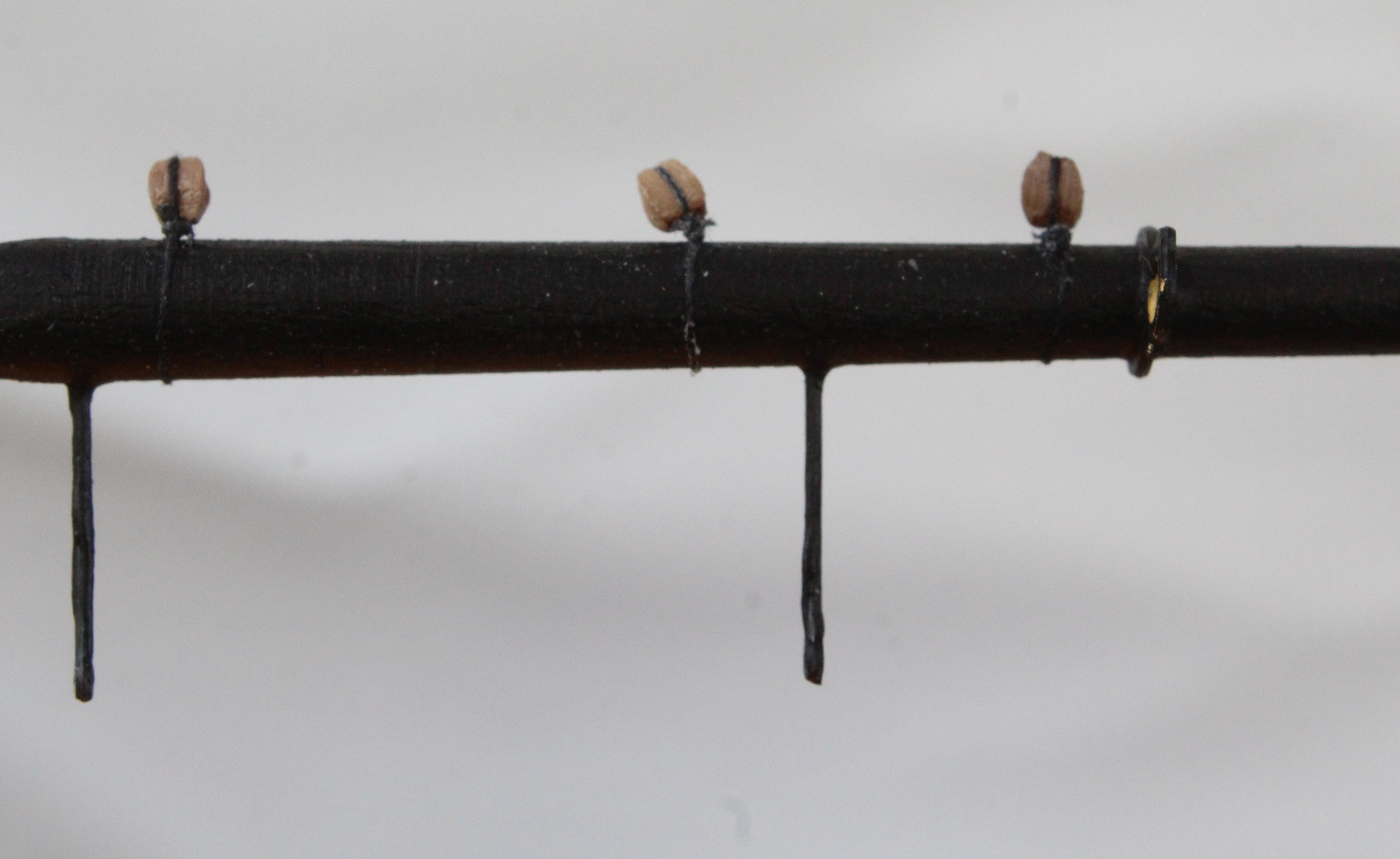
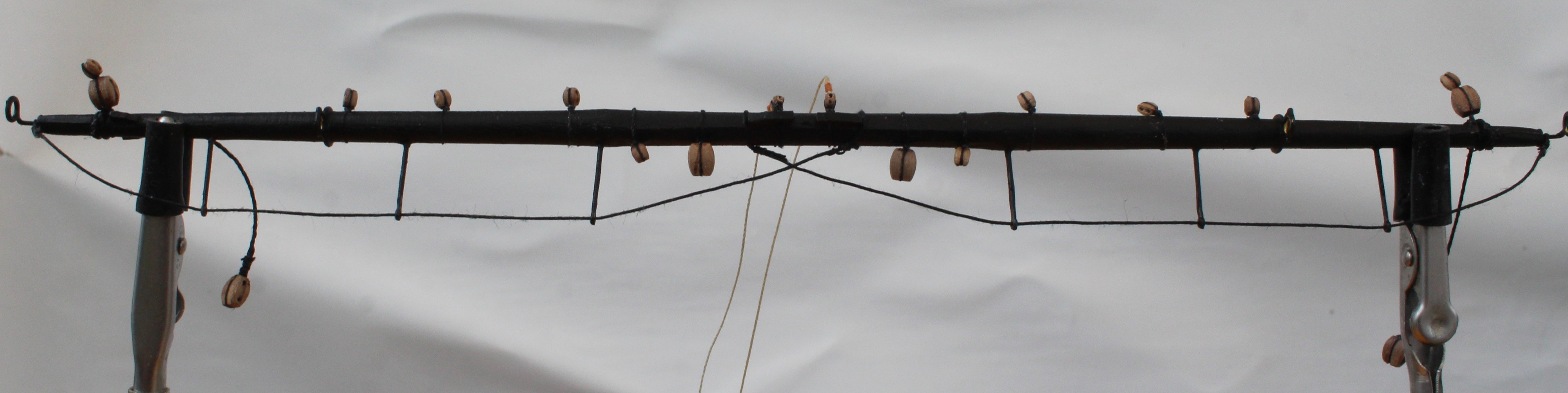
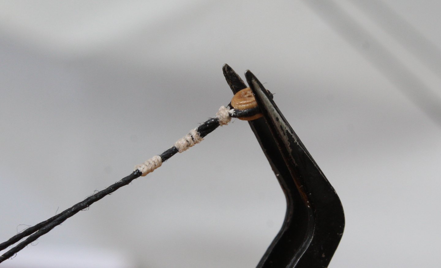
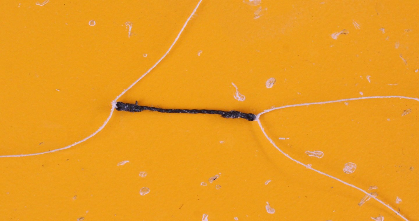
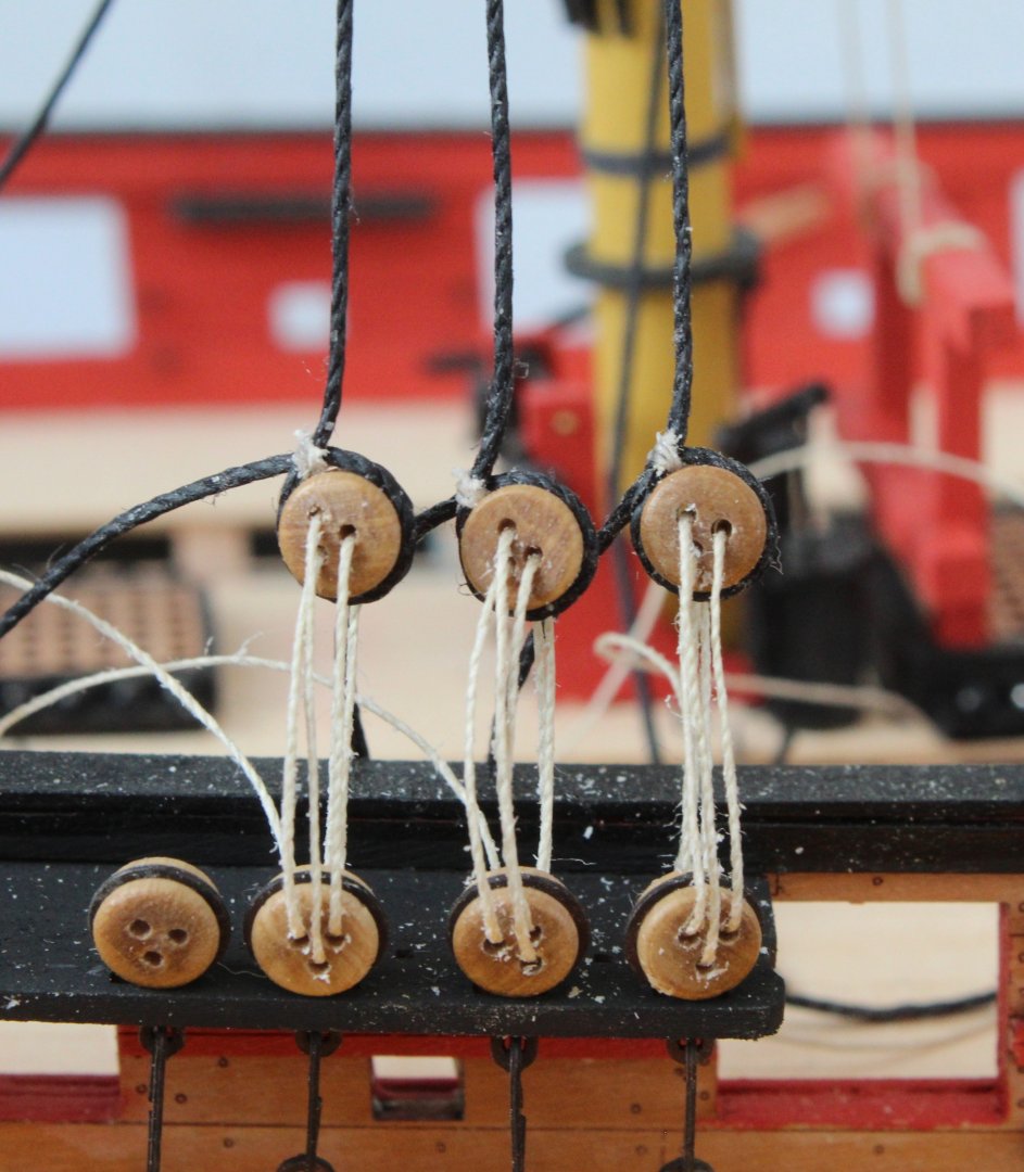
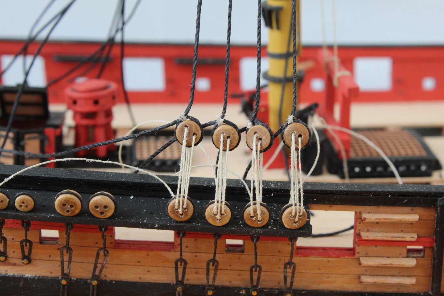
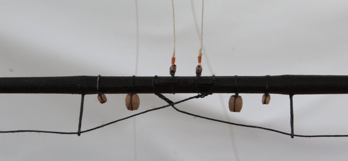
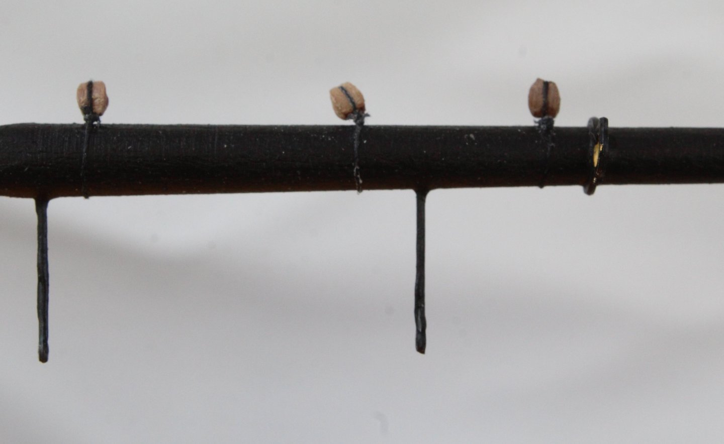
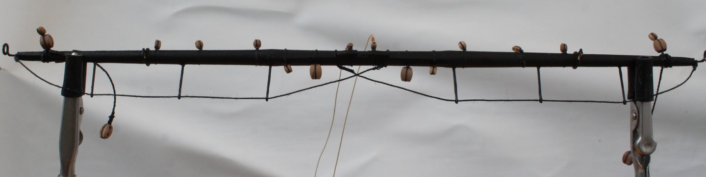
 I have started work on the topmast shrouds. The first task was to make all the shroud pairs for both the main and fore mast. I used a spare piece of dowel to set the loop to the right size so it will fit nicely over the topmast. I have decided to try an experiment with regards to adding the deadeyes to the shroud lines. With the first shroud lines in place I passed some thread through to indicate where the top edge of the deadeye should be positioned so that lanyard distance between the deadeyes would be approx. 6 to 7mm. The deadeye was then sized,, it was much easier to do this off the boat. With a test fit of the completed first shroud pair I am happy with how the method makes the task much easier however I made a slight miscalculation with the position of the shroud deadeyes, as the lanyard spacing is approx. 10mm which is too much.
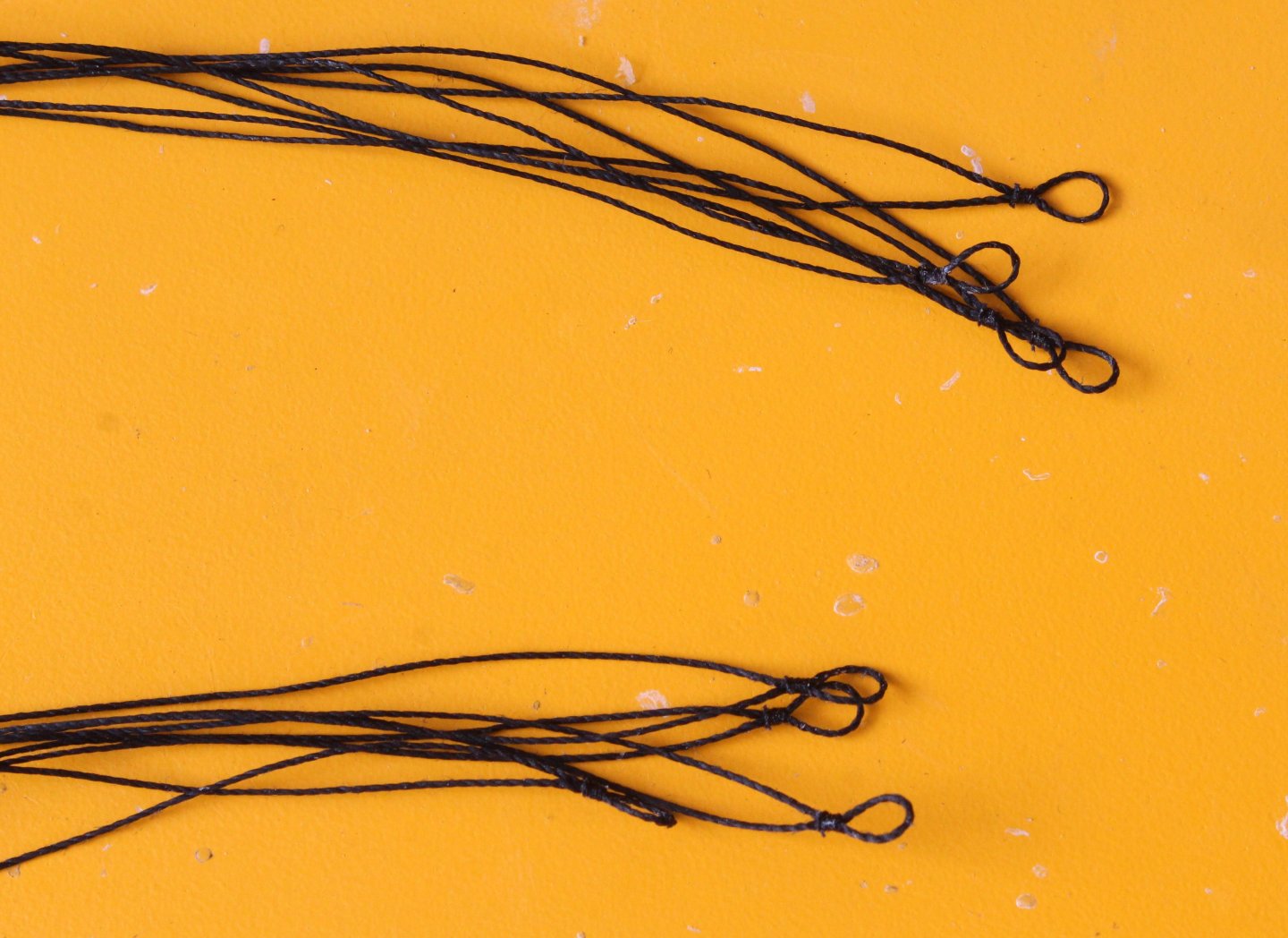
- 241 replies
-
- 13
-

-
- Vanguarrd Models
- Harpy
- (and 1 more)
-
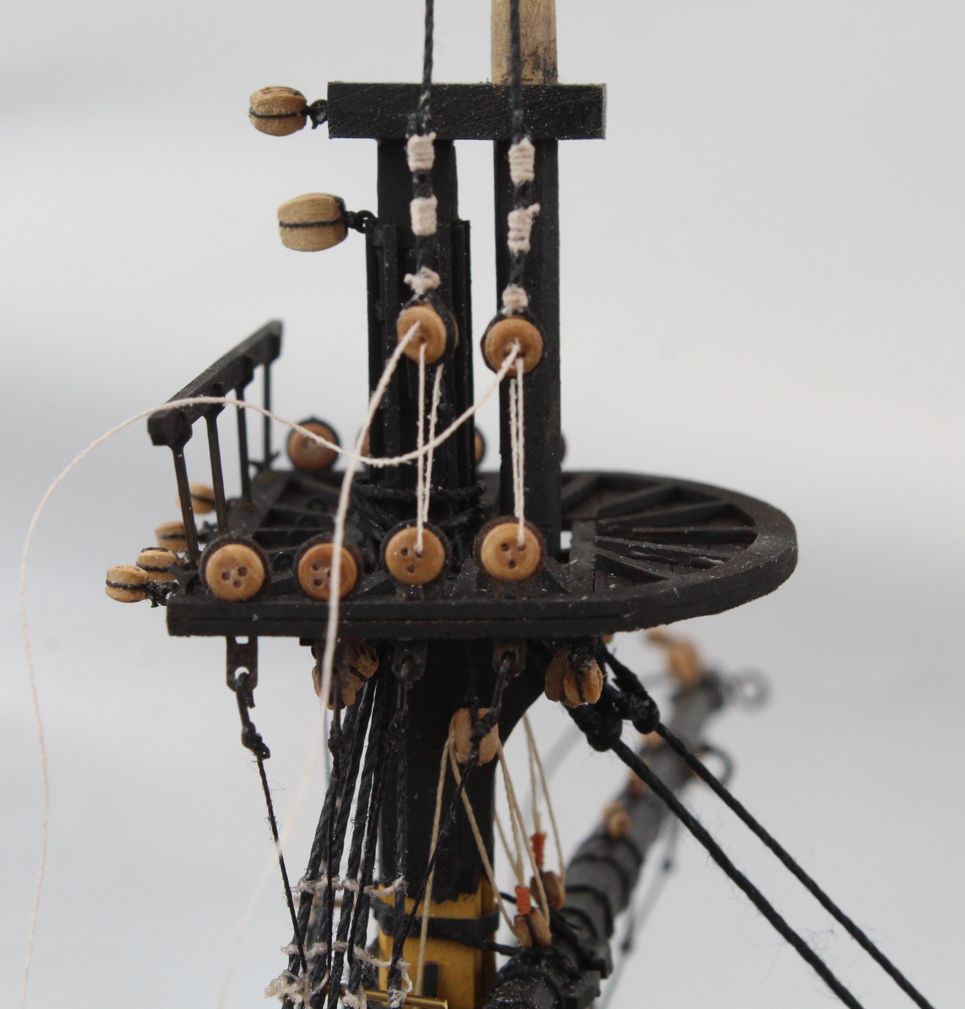
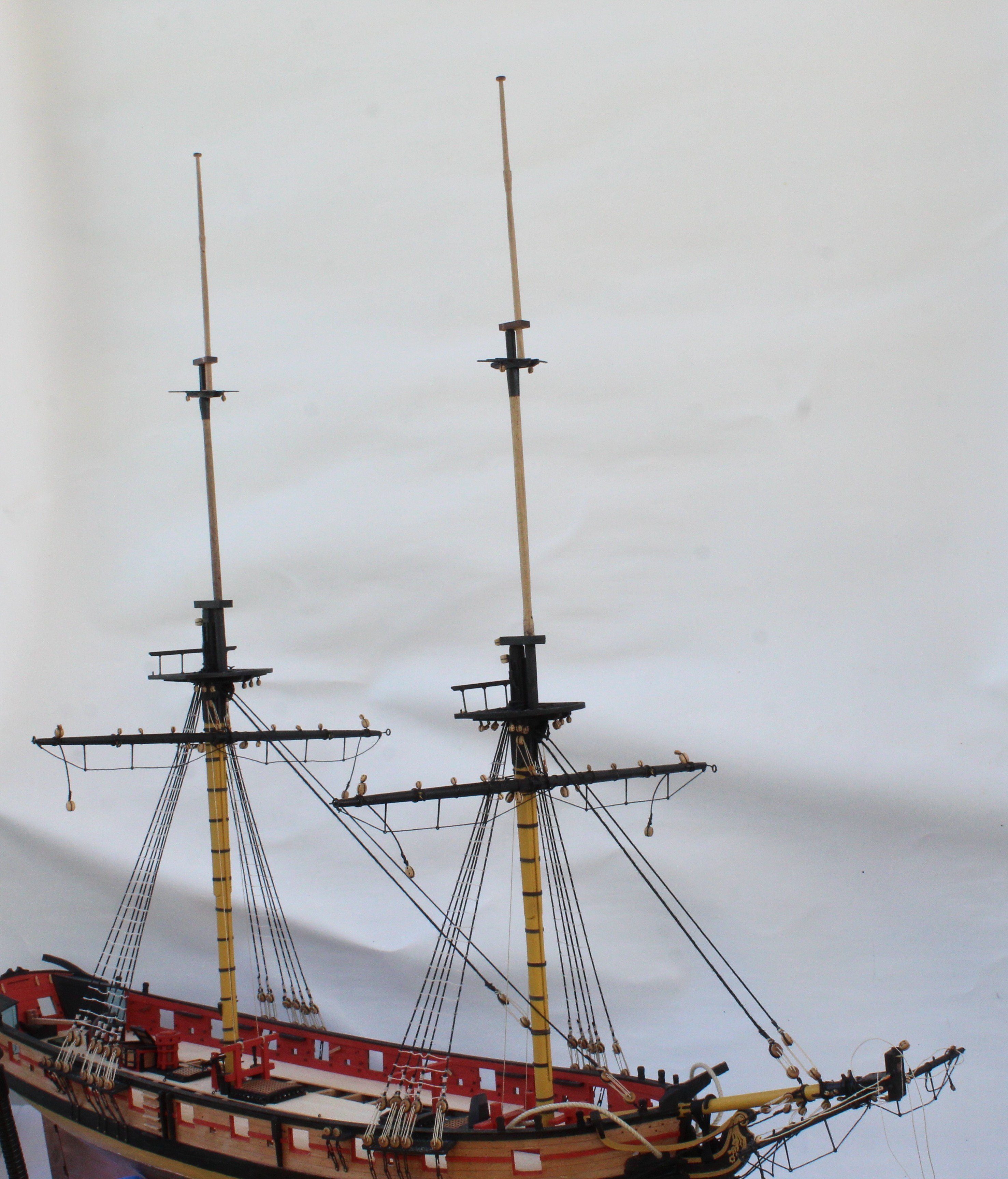
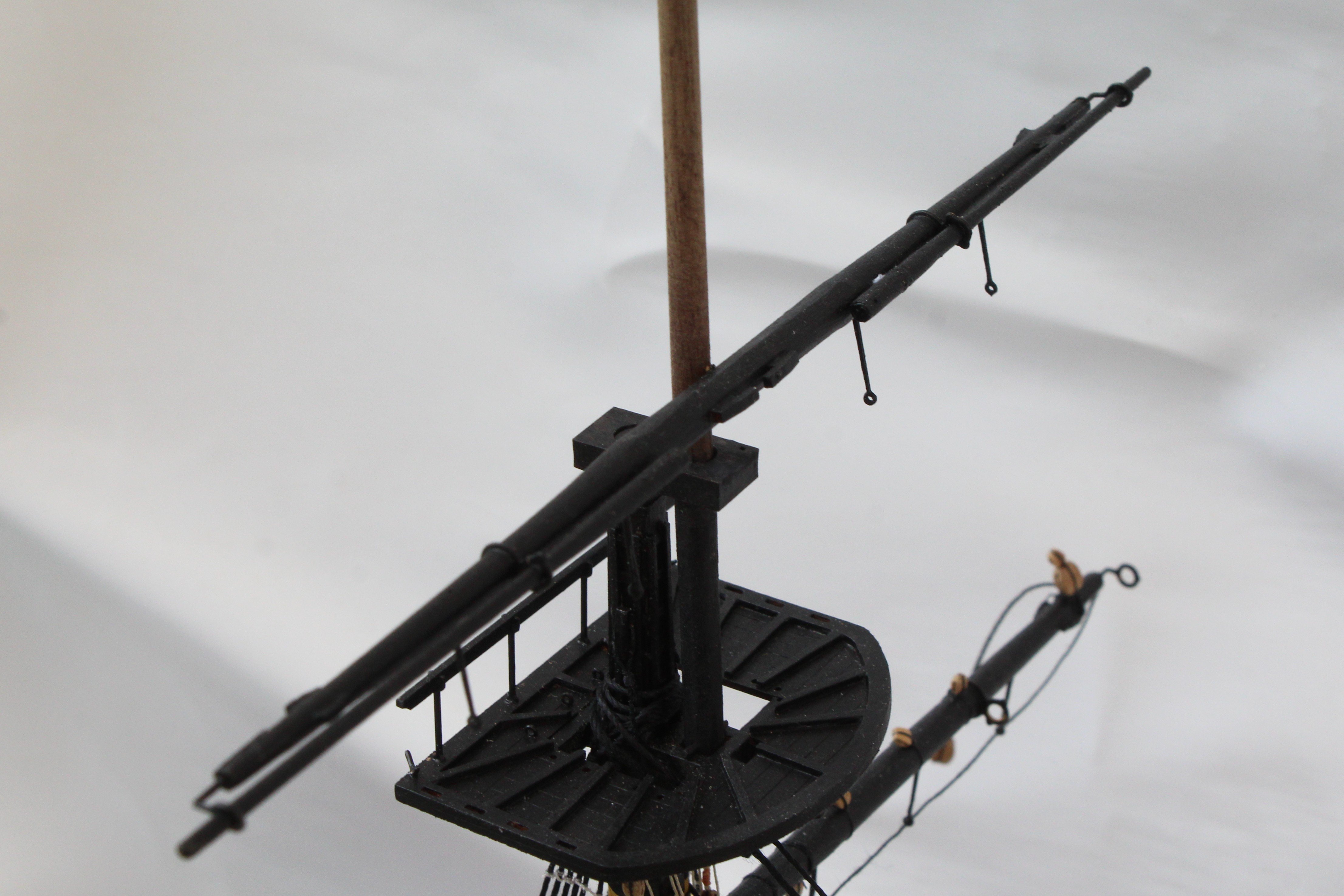
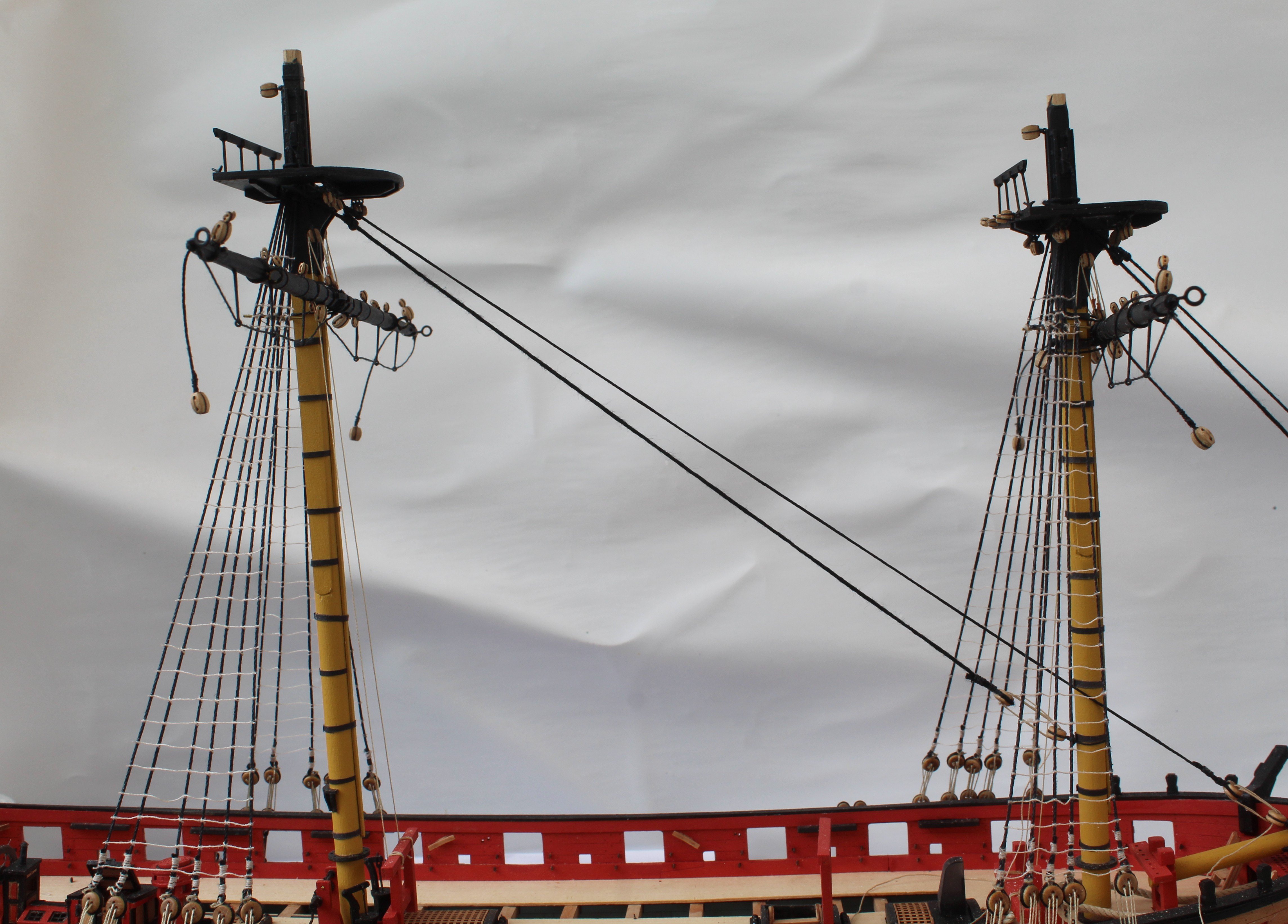
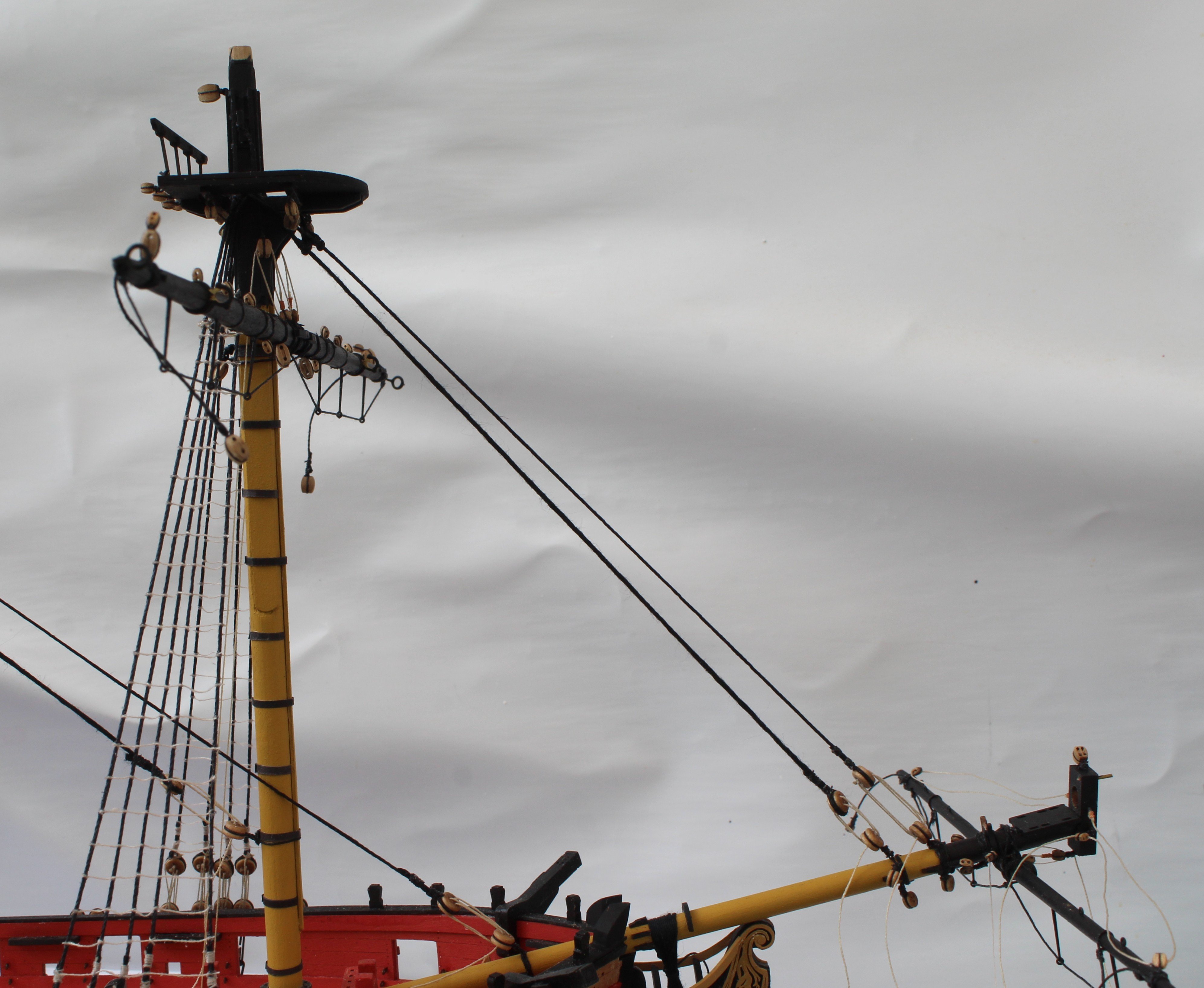
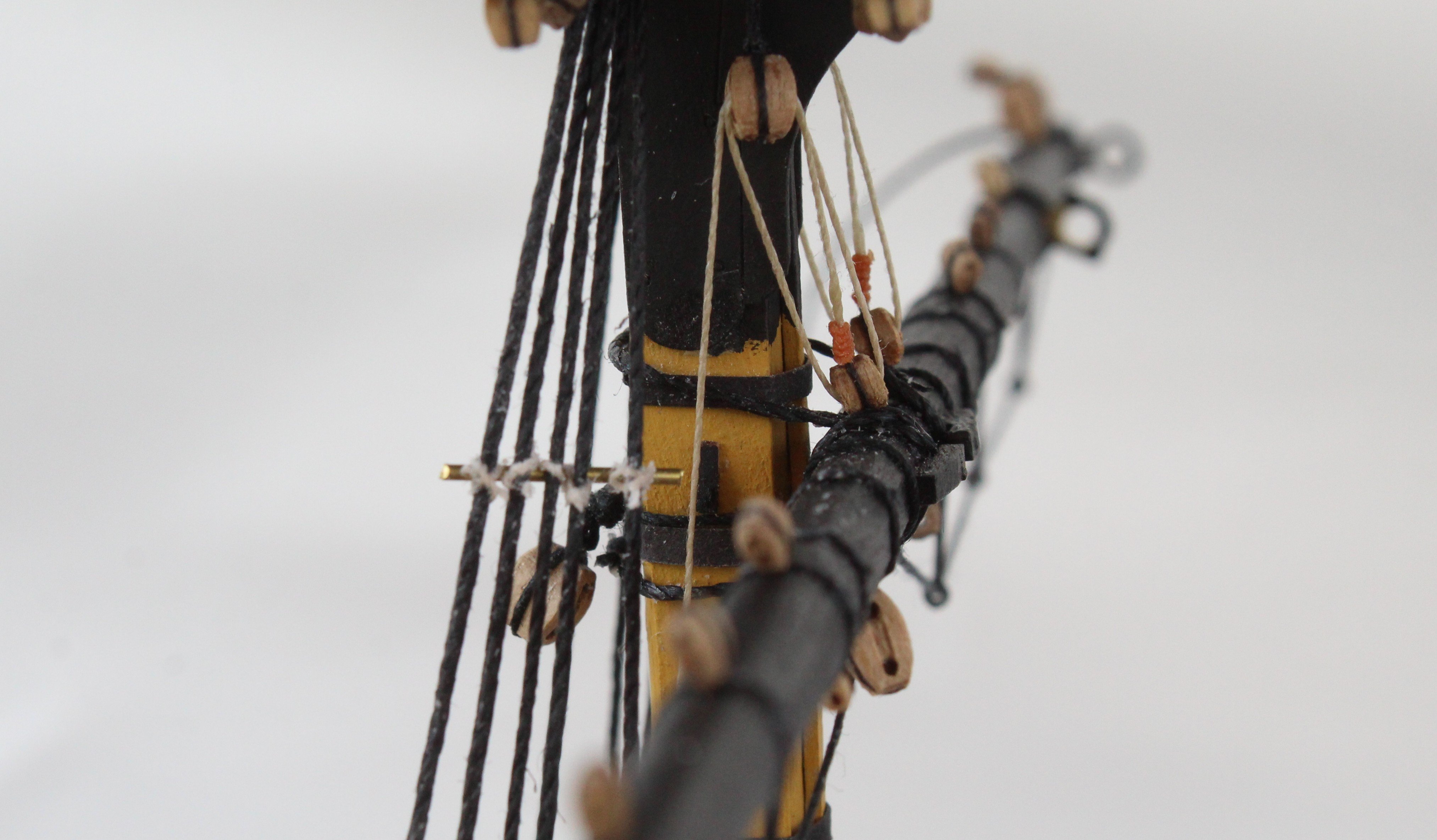
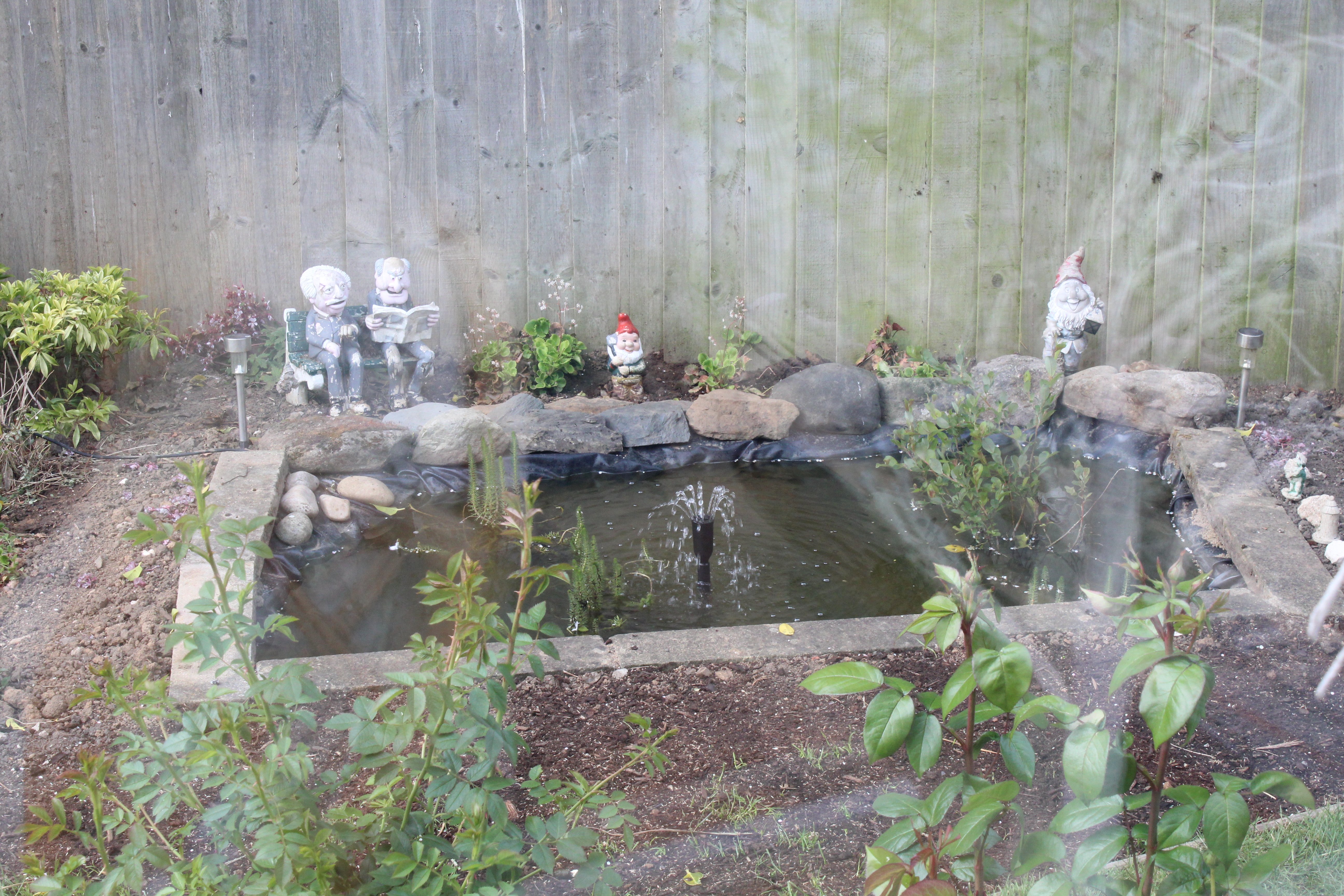
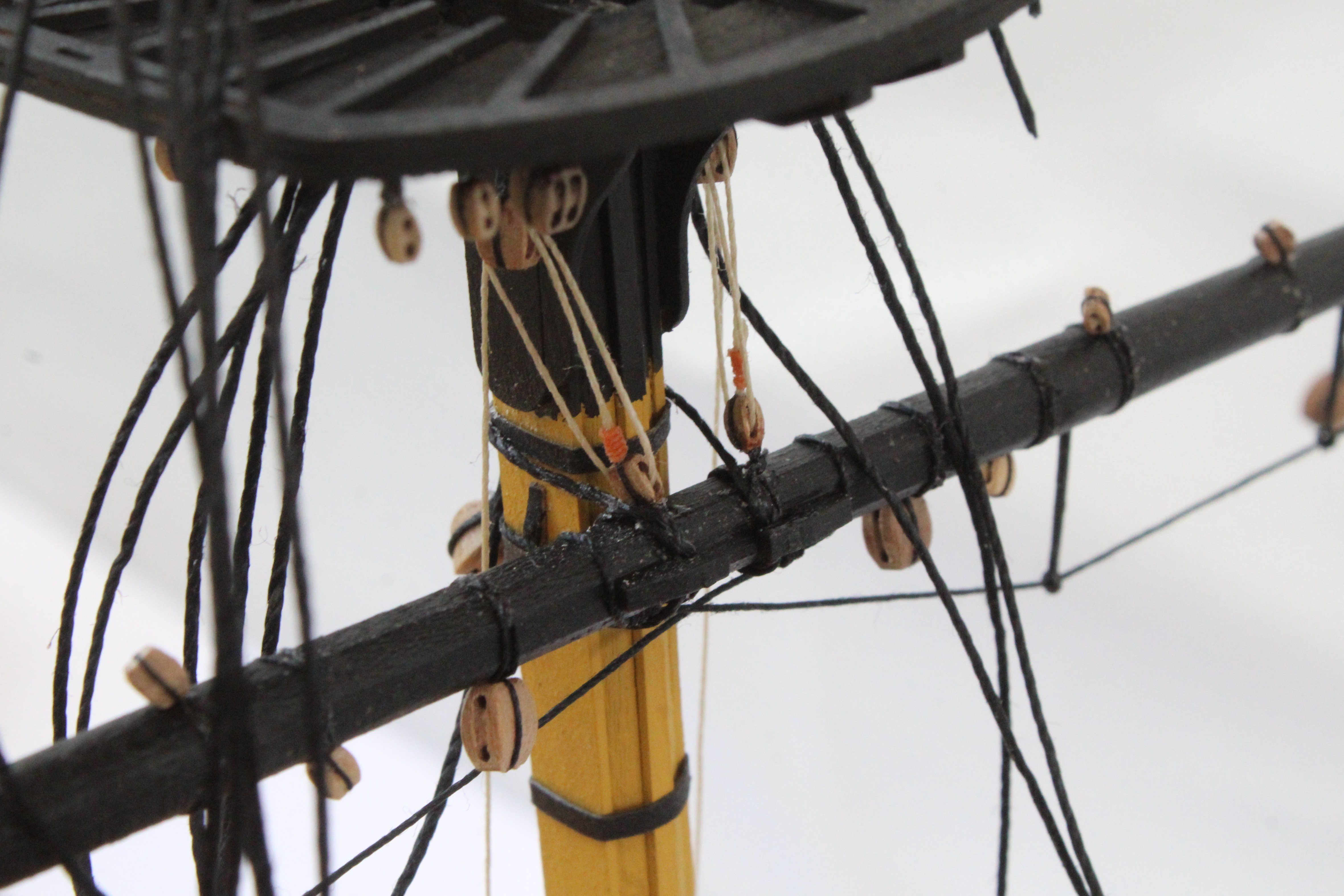
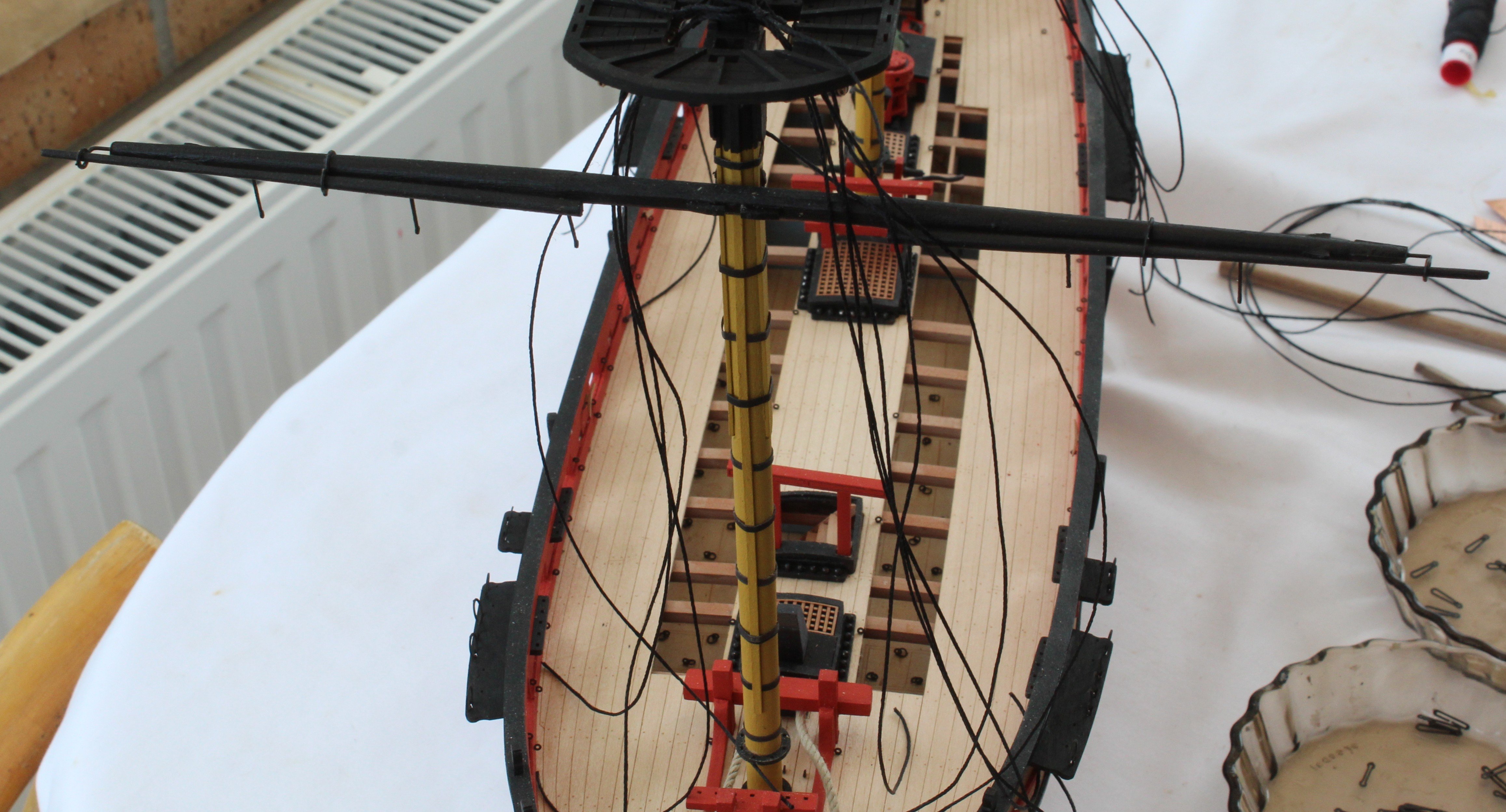
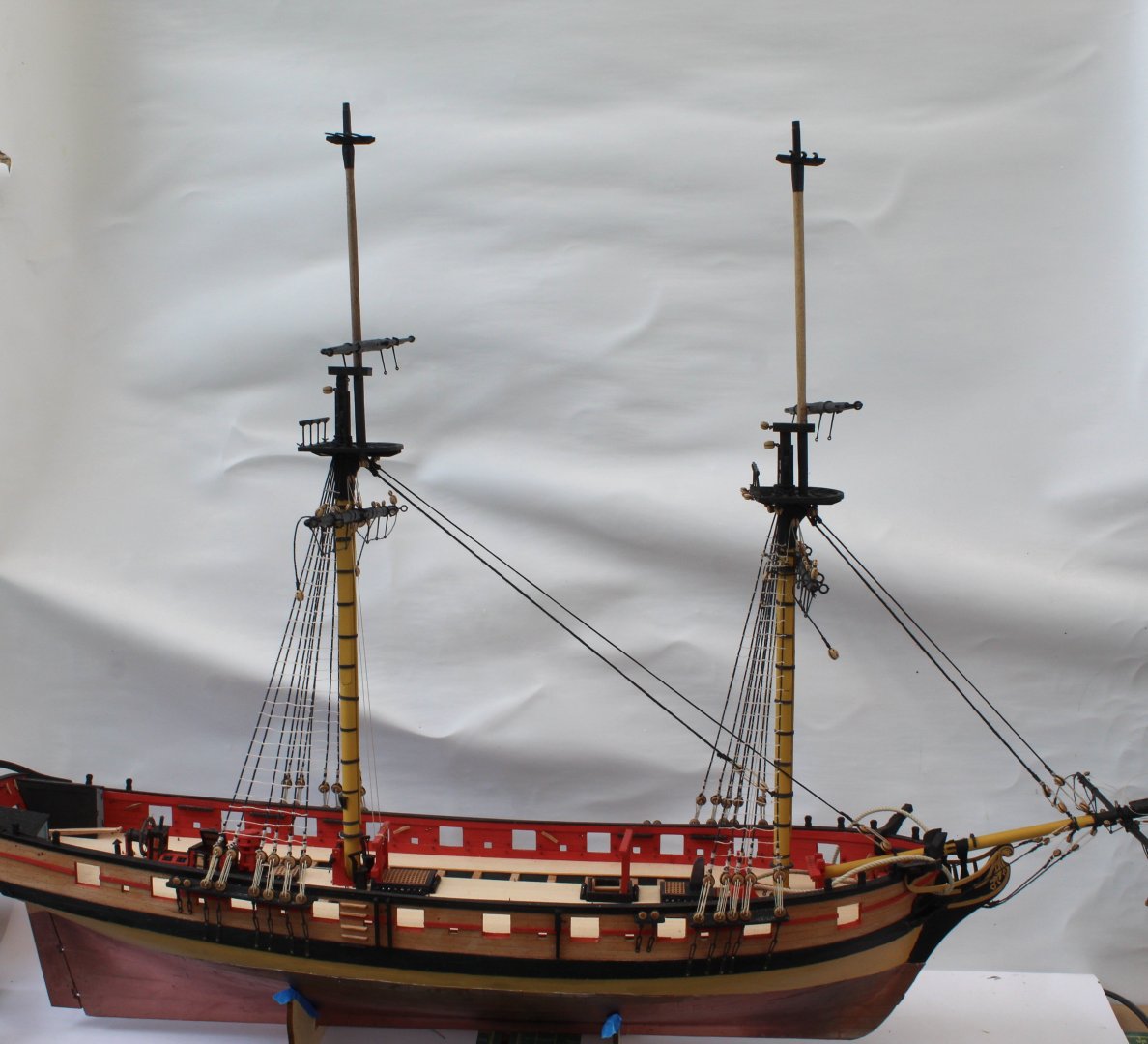
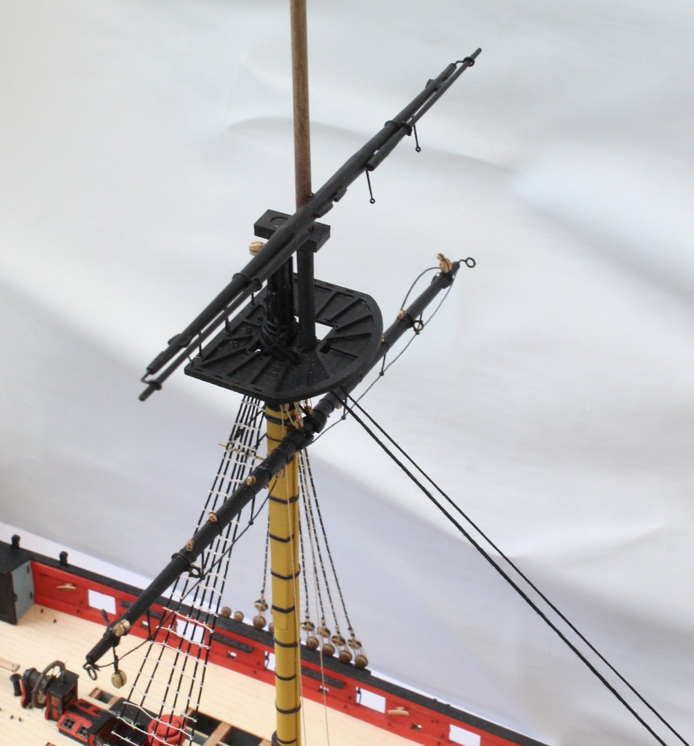
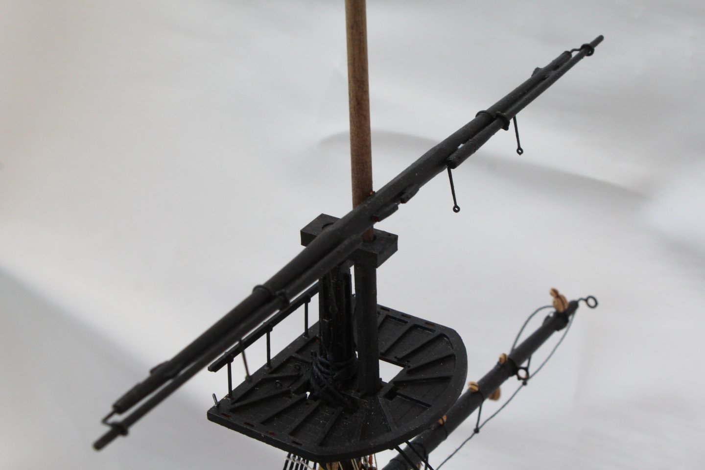
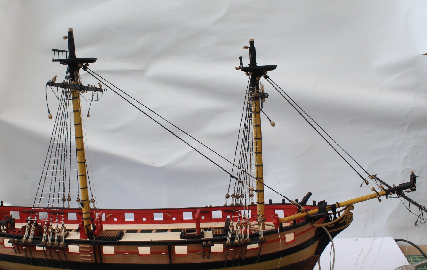
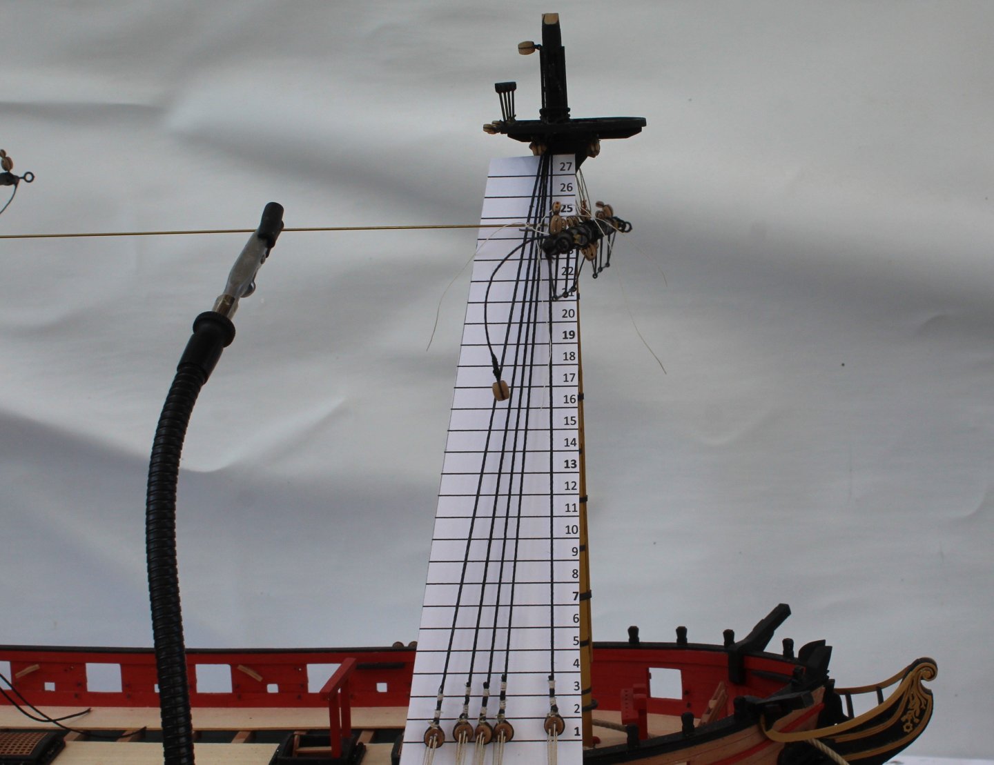
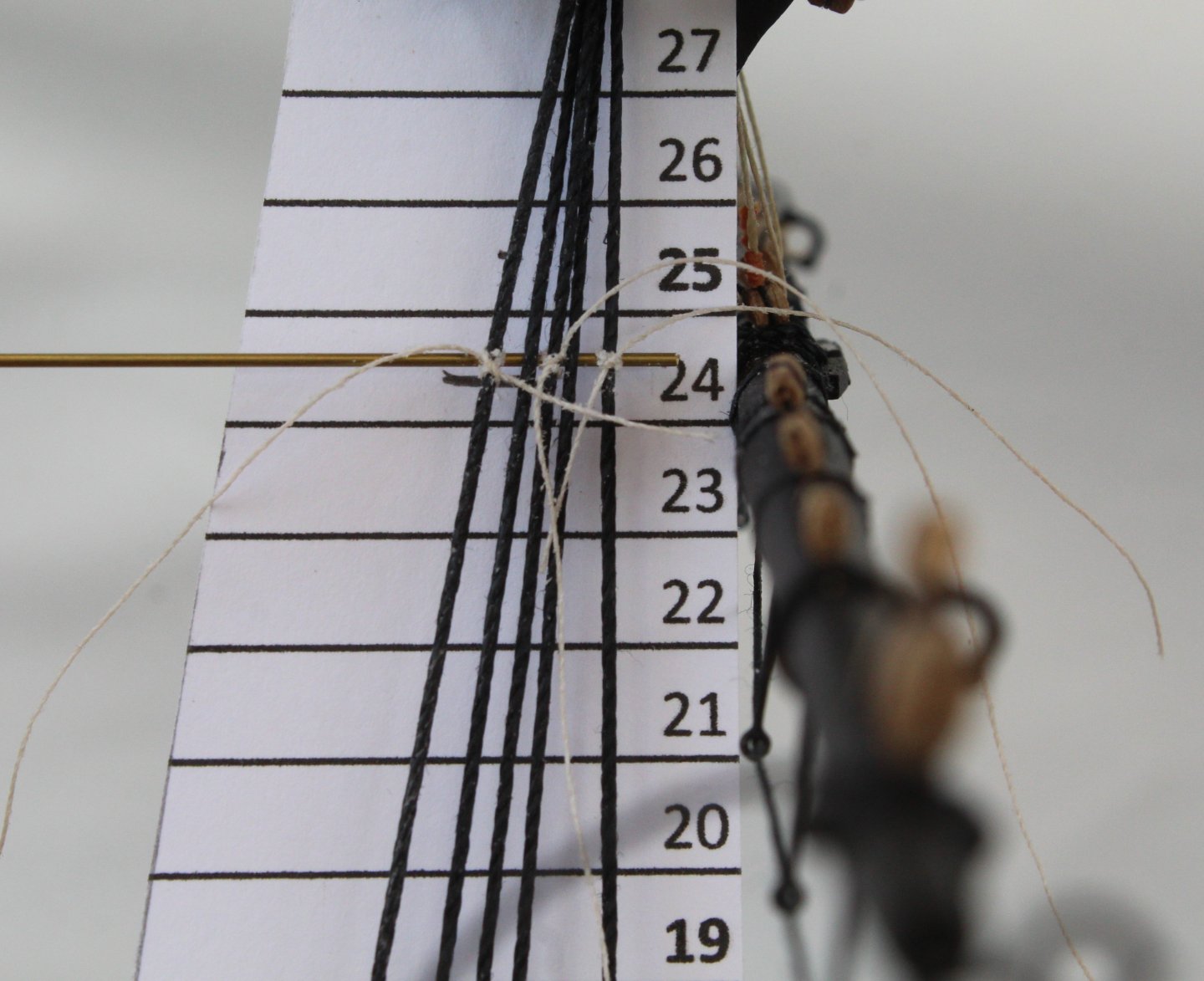
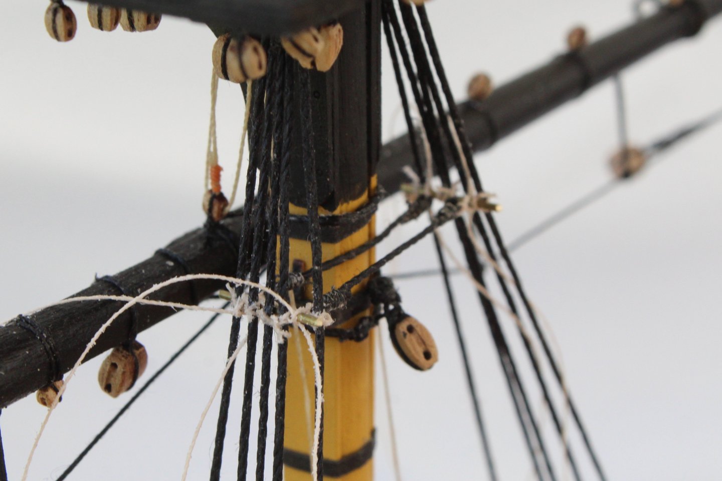
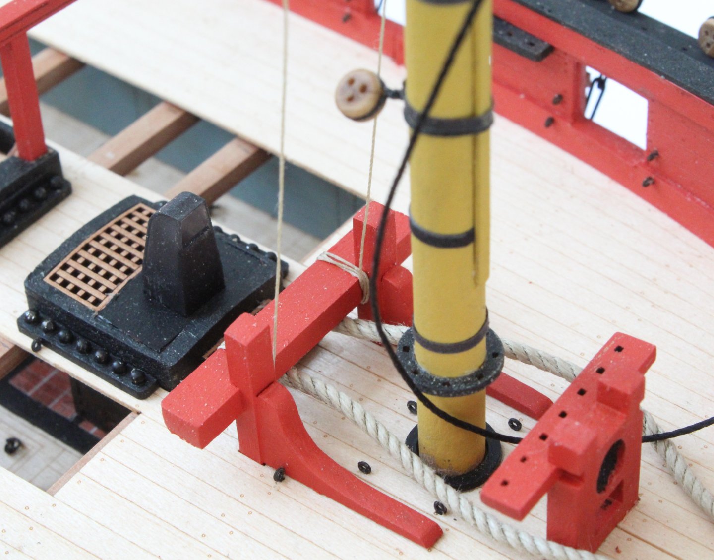
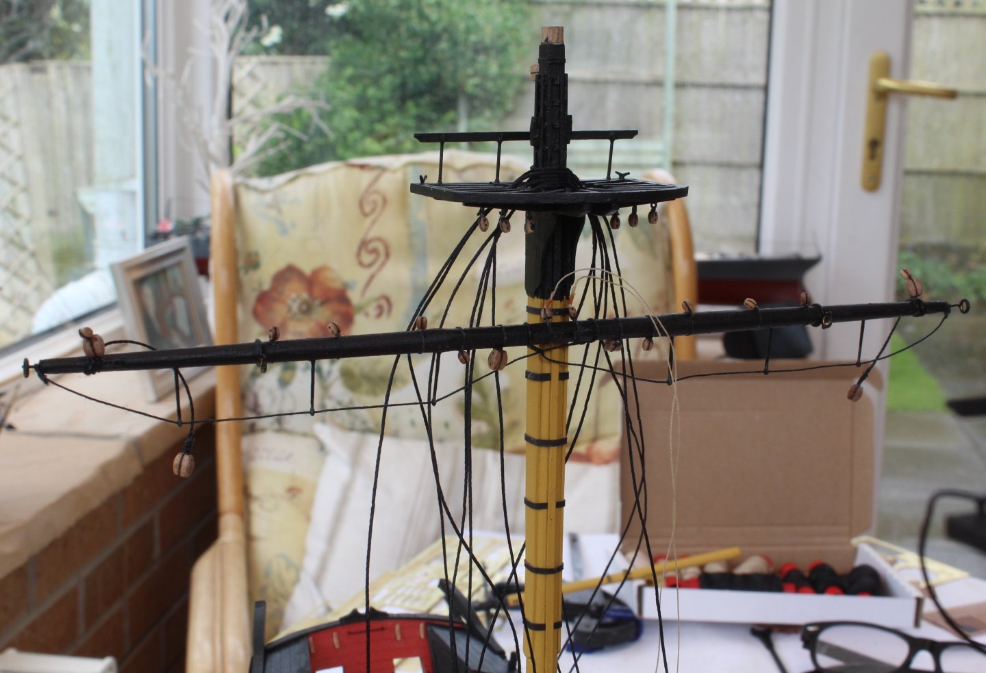
After a weekend away looking after some of our grandchildren I have now been able to spend a little bit of time in the shipyard. The main and fore topsail masts and associated platforms were painted as shown in the plan sheets and then test fitted, as shown below. I then did a quick test fit of the main and fore topgallant masts. Next I did a test fit of the main and fore topsail yards. I am happy with how they look. They will now be removed and will fitted at a later stage in the rigging process. My next task, I thought, would be to add the topsail shrouds. However I then realised I had forgotten to add the futtock stave rigging. This is now currently work in progress and will keep me busy for the next few days. I have added a couple of photos of my progress to date.


- 241 replies
-
- 11
-
-
- Vanguarrd Models
- Harpy
- (and 1 more)
-
Moving on slowly I have now added the bowsprit shrouds and stays. As can be seen in the first set of photos below the lanyards have been run in but not tied off. In the next set of photos the lanyards have been tied off, starting with the main and foremast stays and preventor stays. This is not some of my finest work but I am pleased to have completed this part of the rigging.


- 241 replies
-
- 8
-
-
- Vanguarrd Models
- Harpy
- (and 1 more)
-
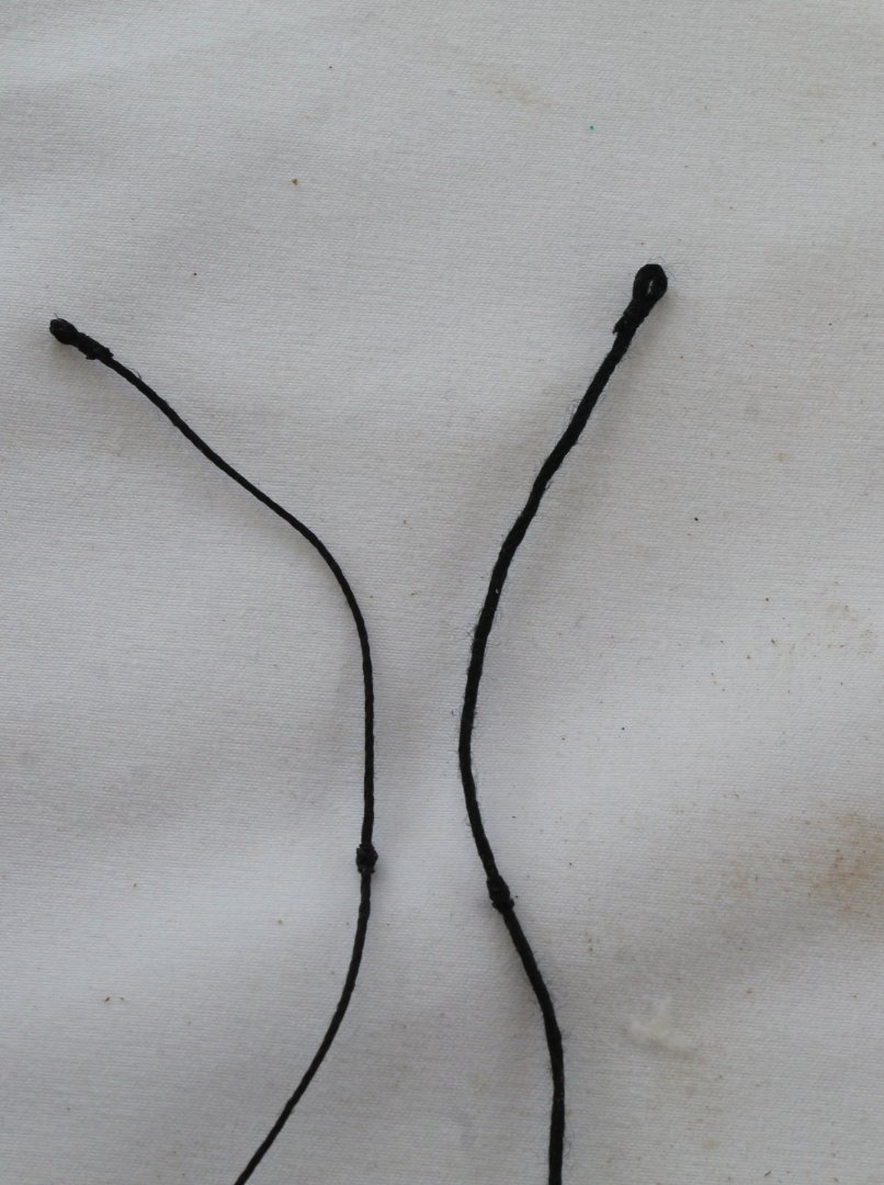
I am still basking in the warm sunshine and spending much of my time in the garden and very little time in the shipyard. I have been able to add the main and foremast stays and preventor stays. I am reasonably happy with how they look. I opted to make my own mouse parts rather than using the kit supplied parts. The lanyards have not been tied off as yet.


- 241 replies
-
- 15
-
-

-
- Vanguarrd Models
- Harpy
- (and 1 more)
-
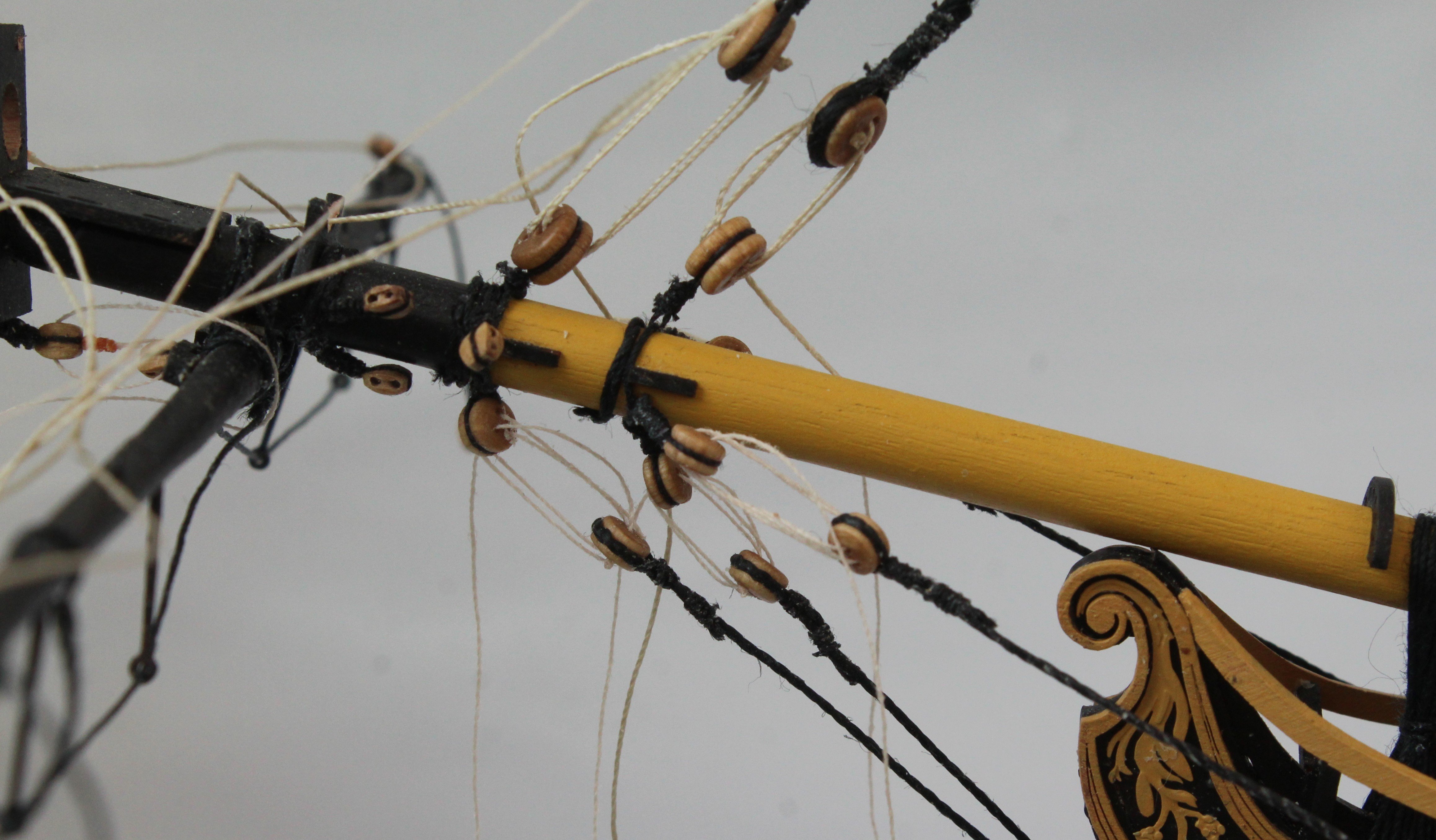
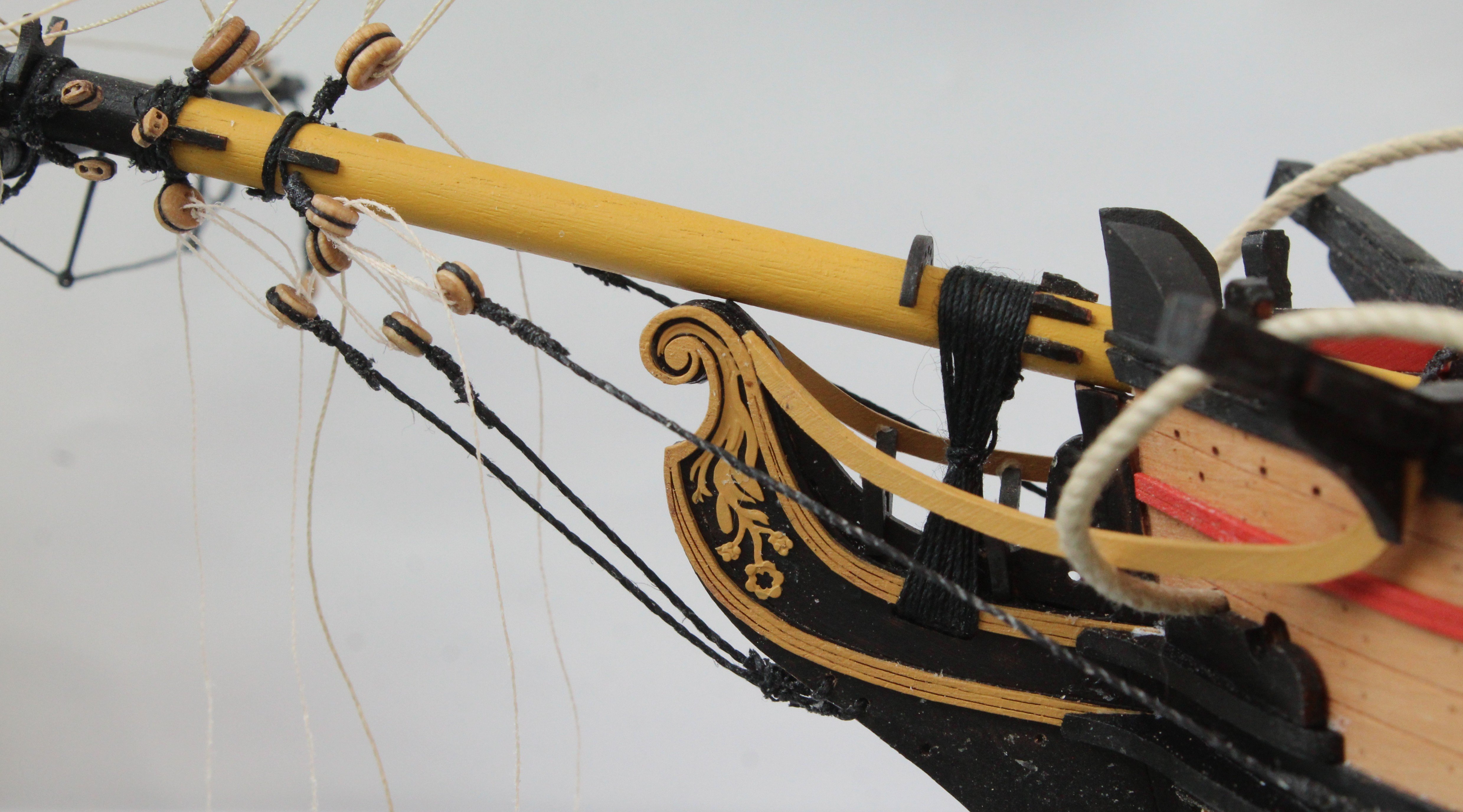
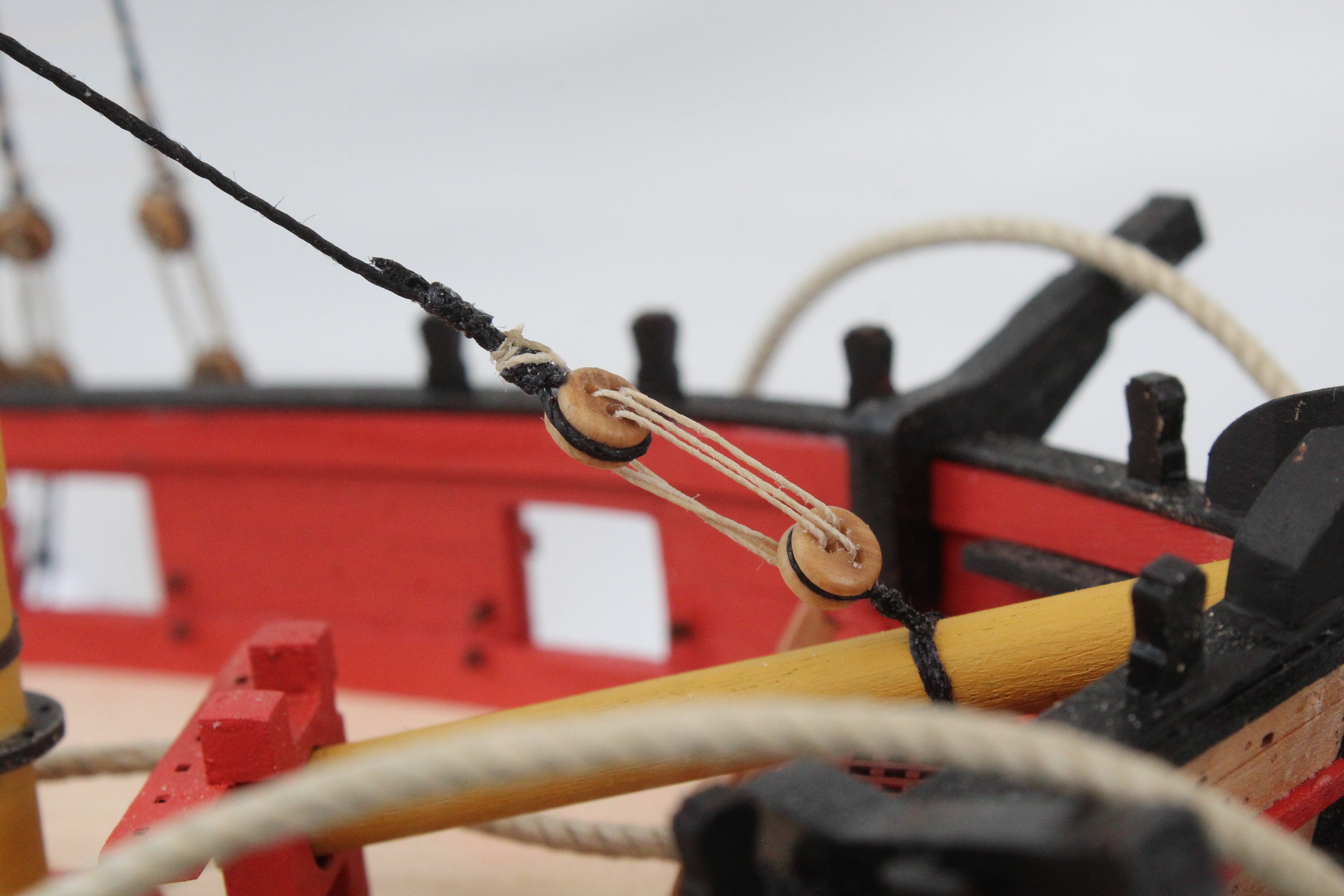
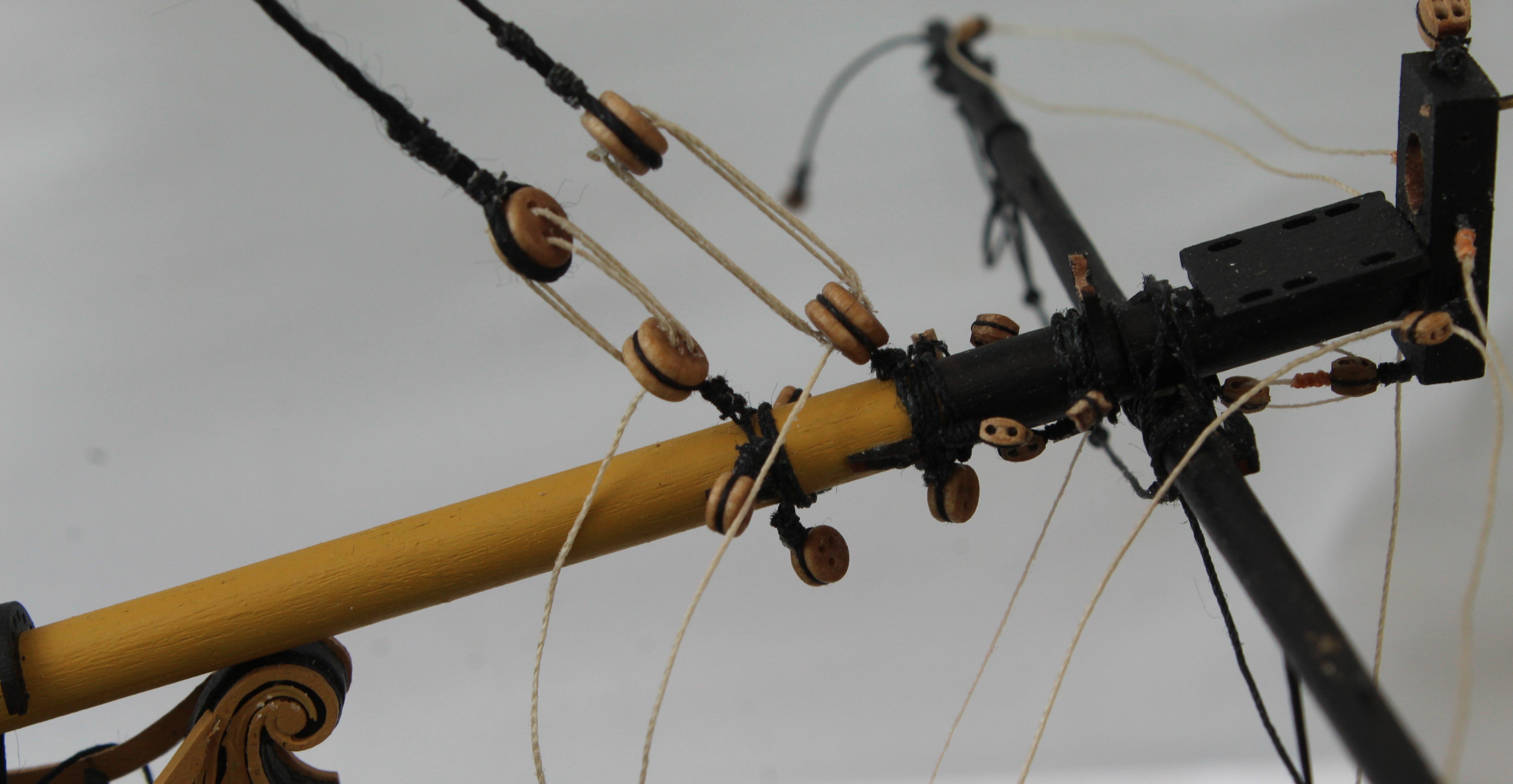
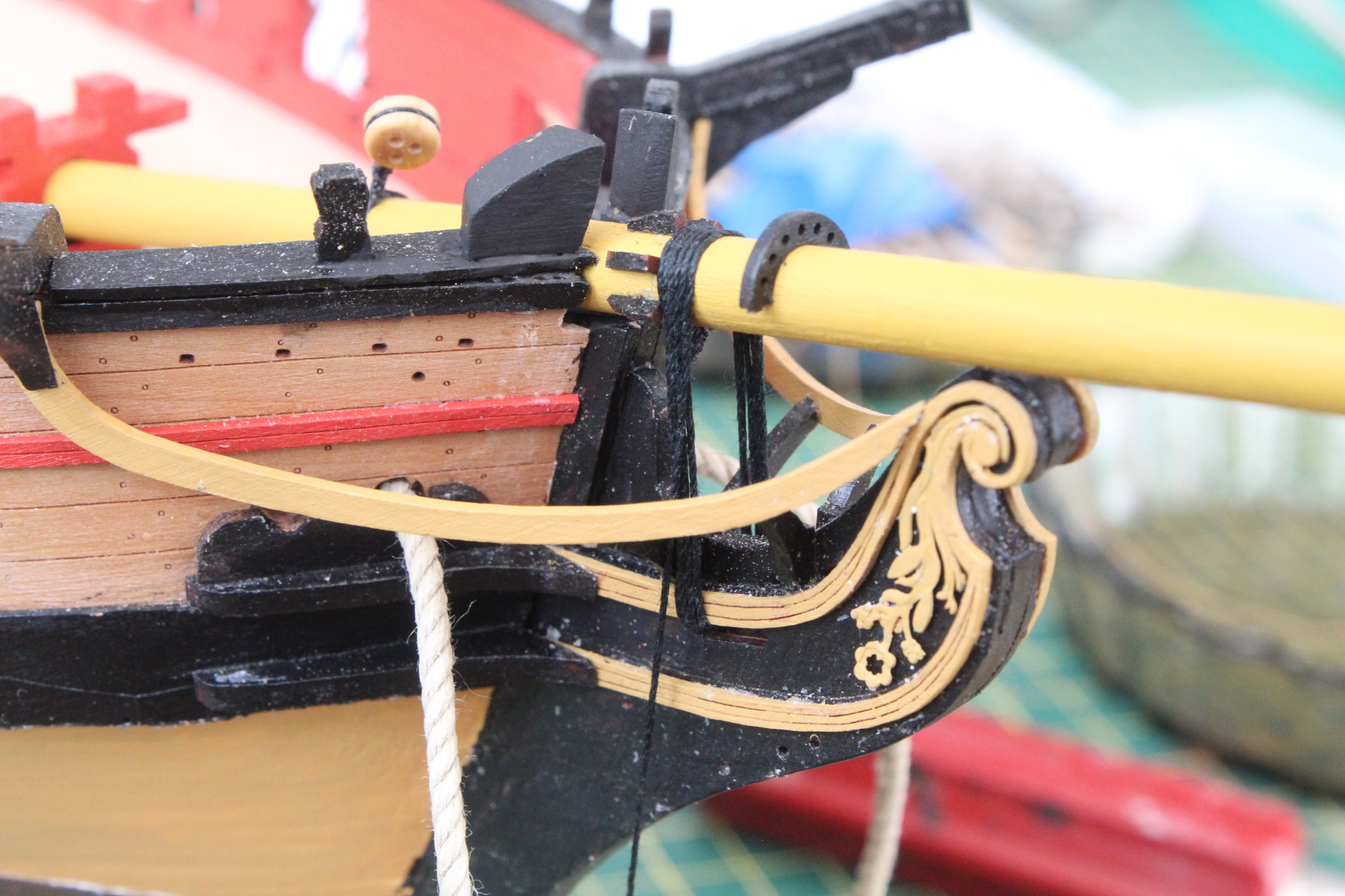
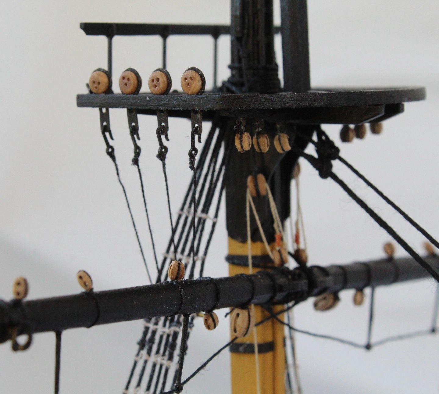
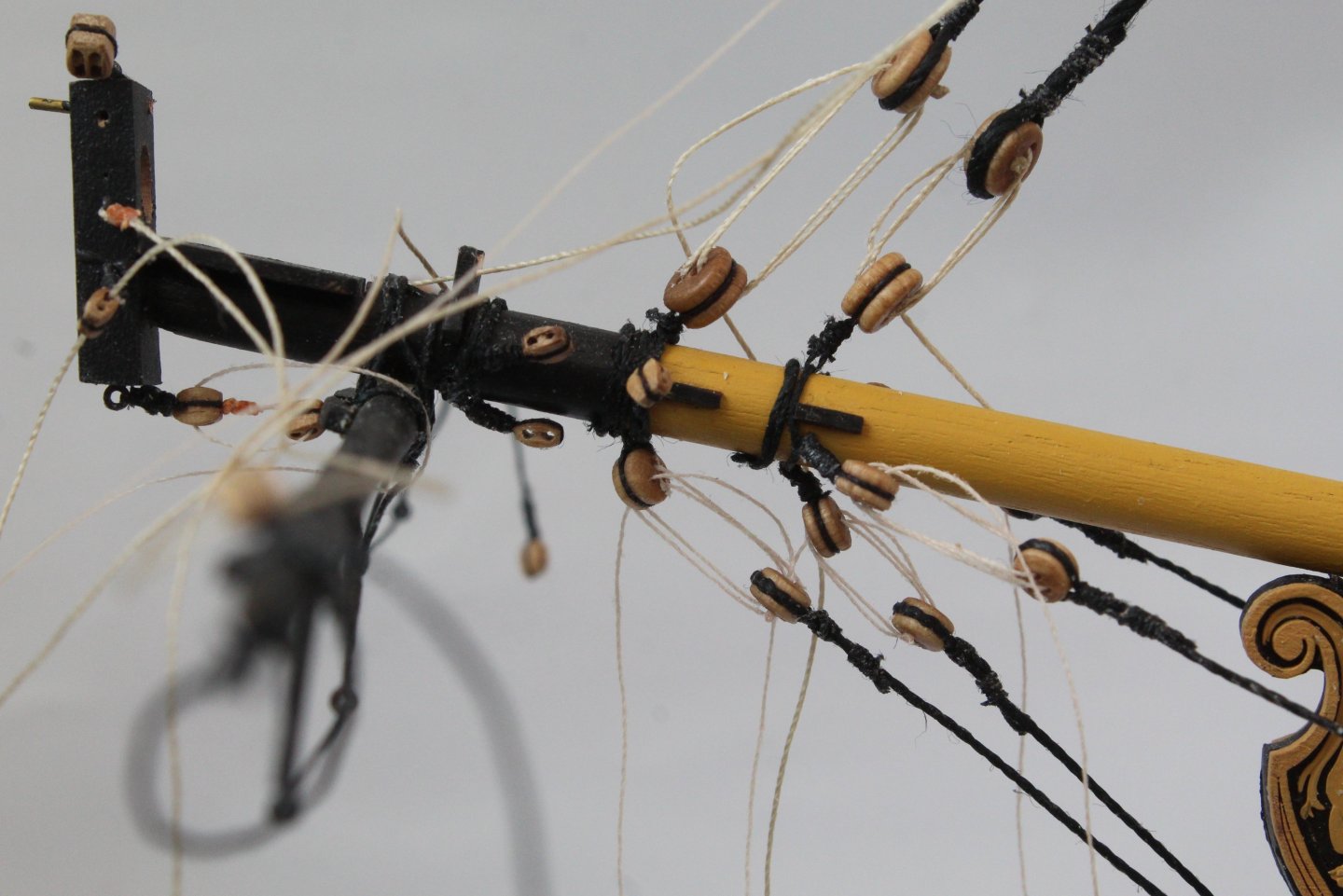
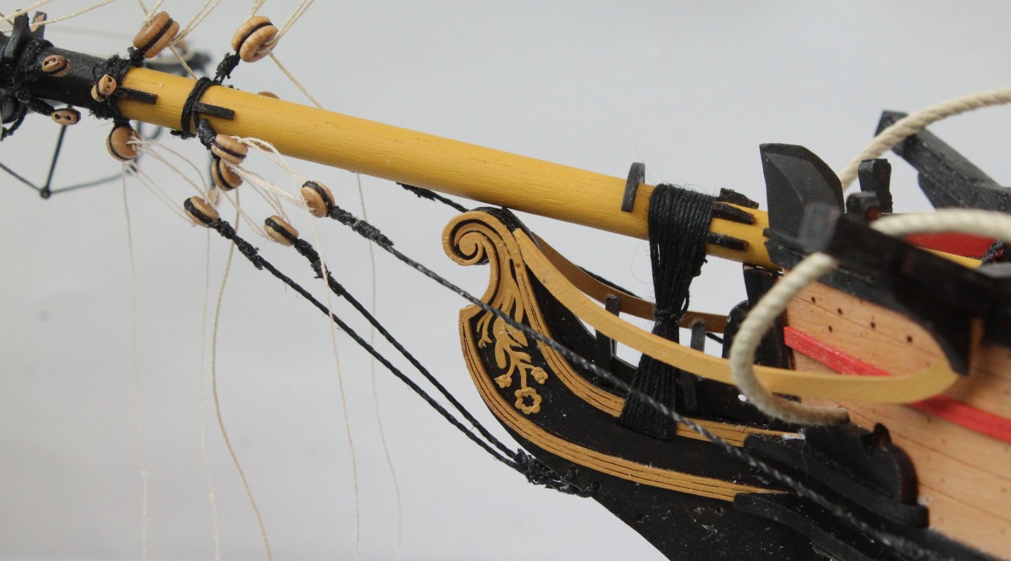
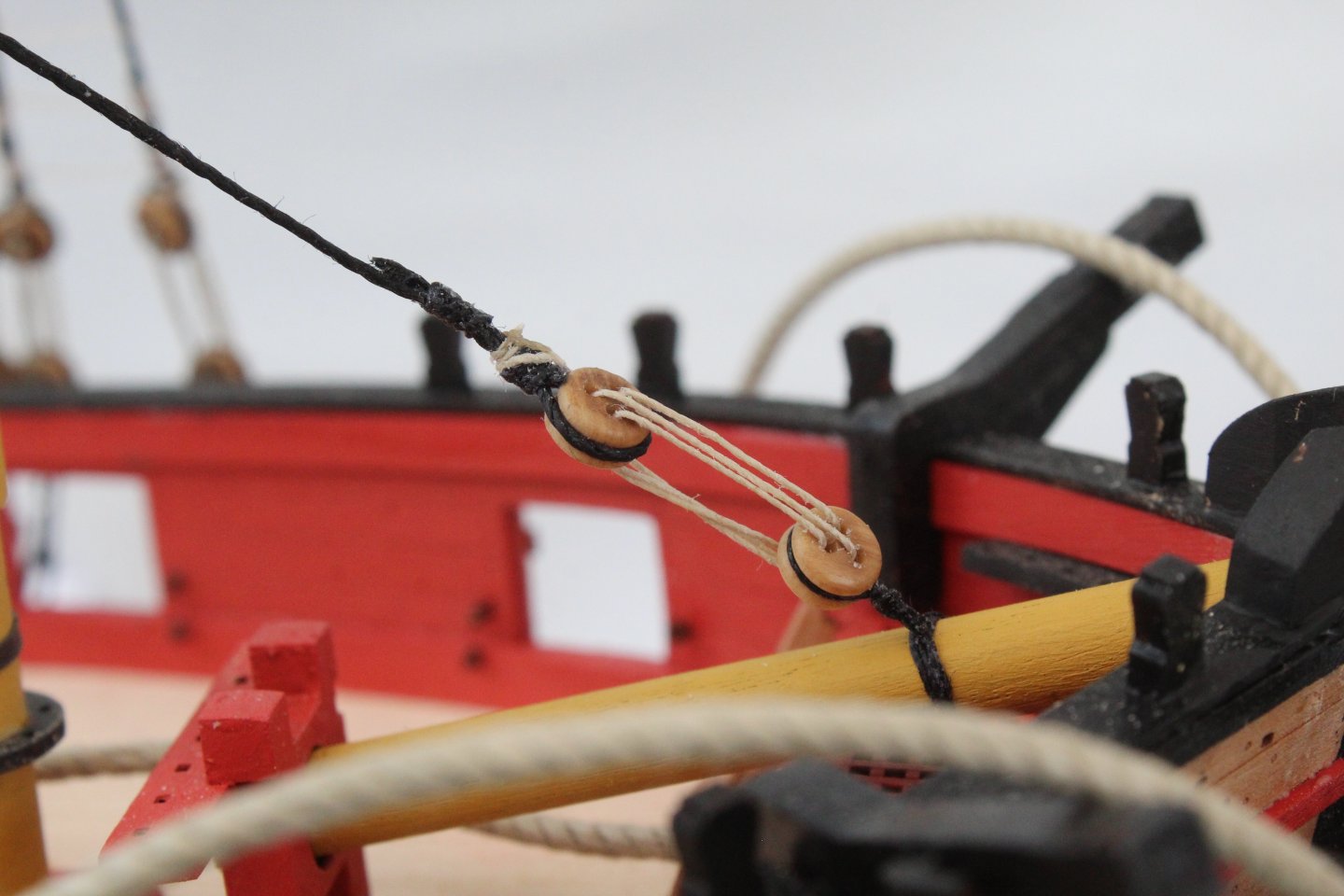
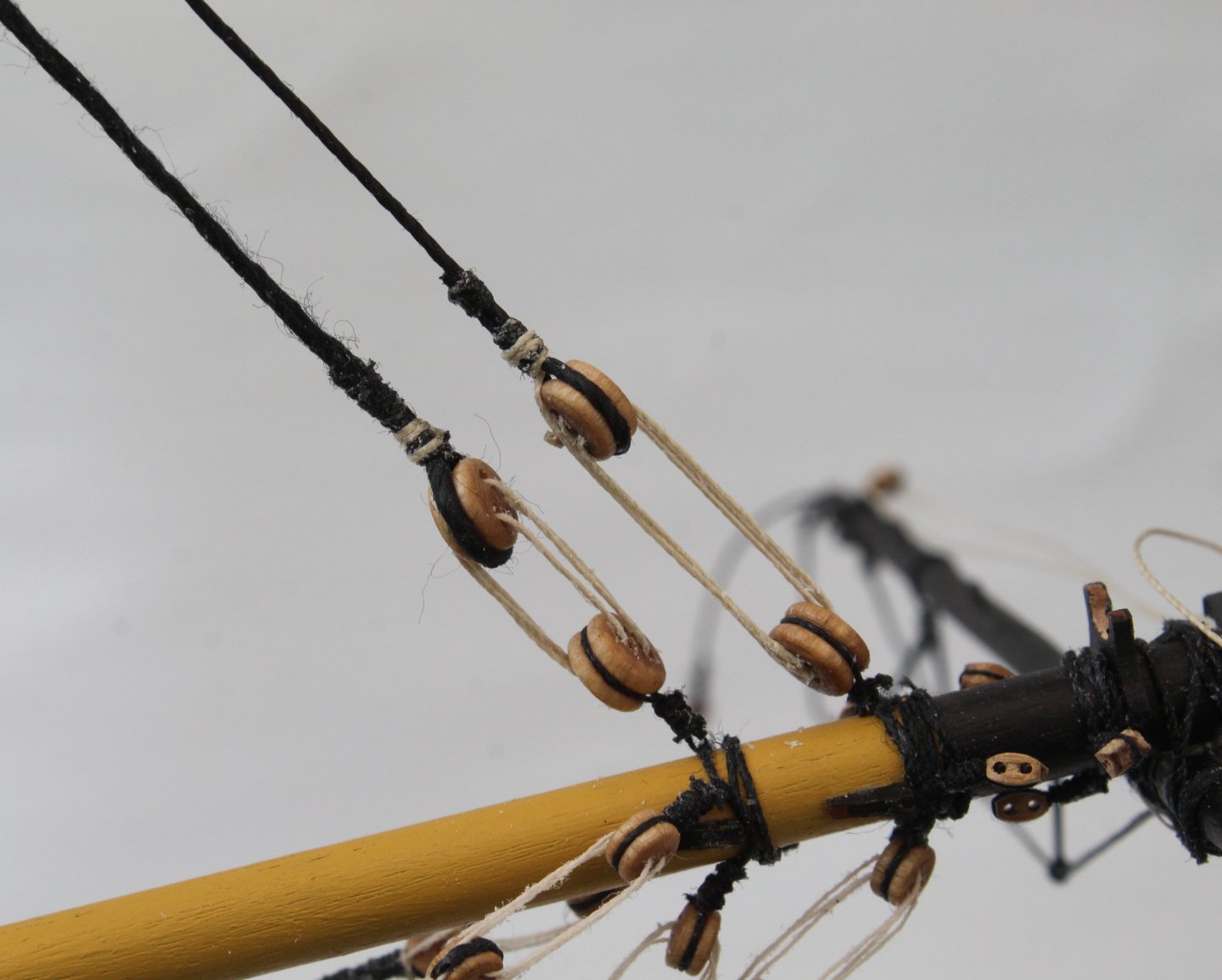
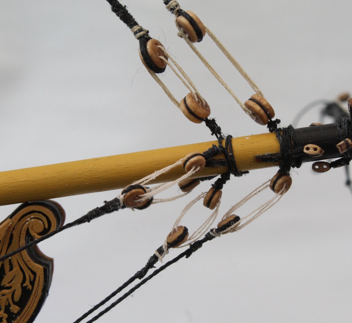
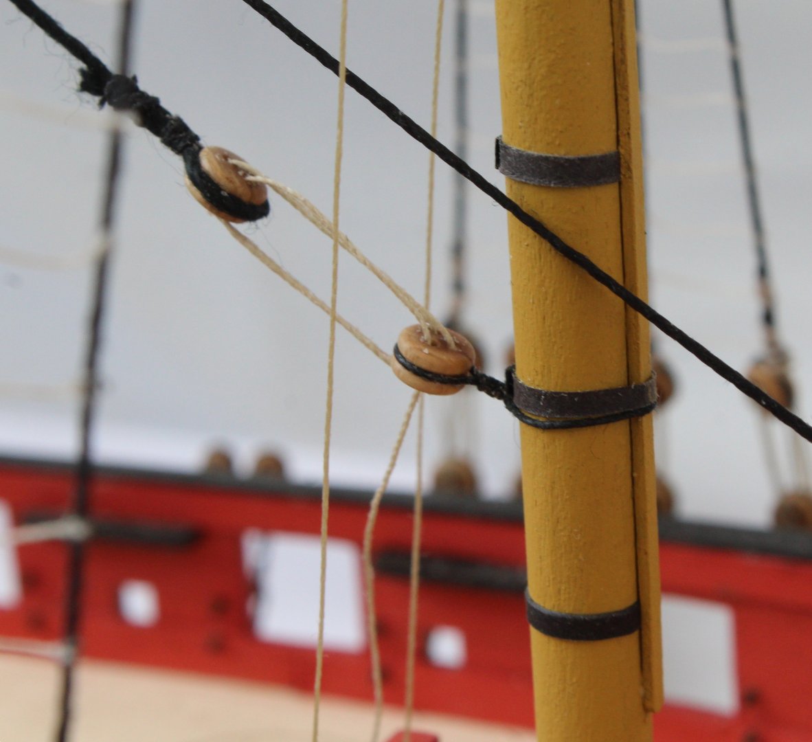
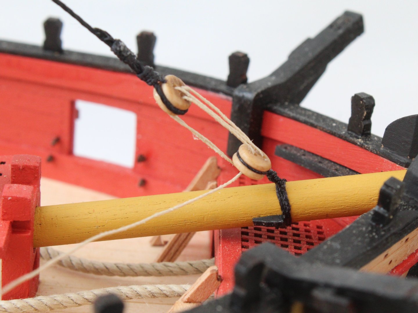
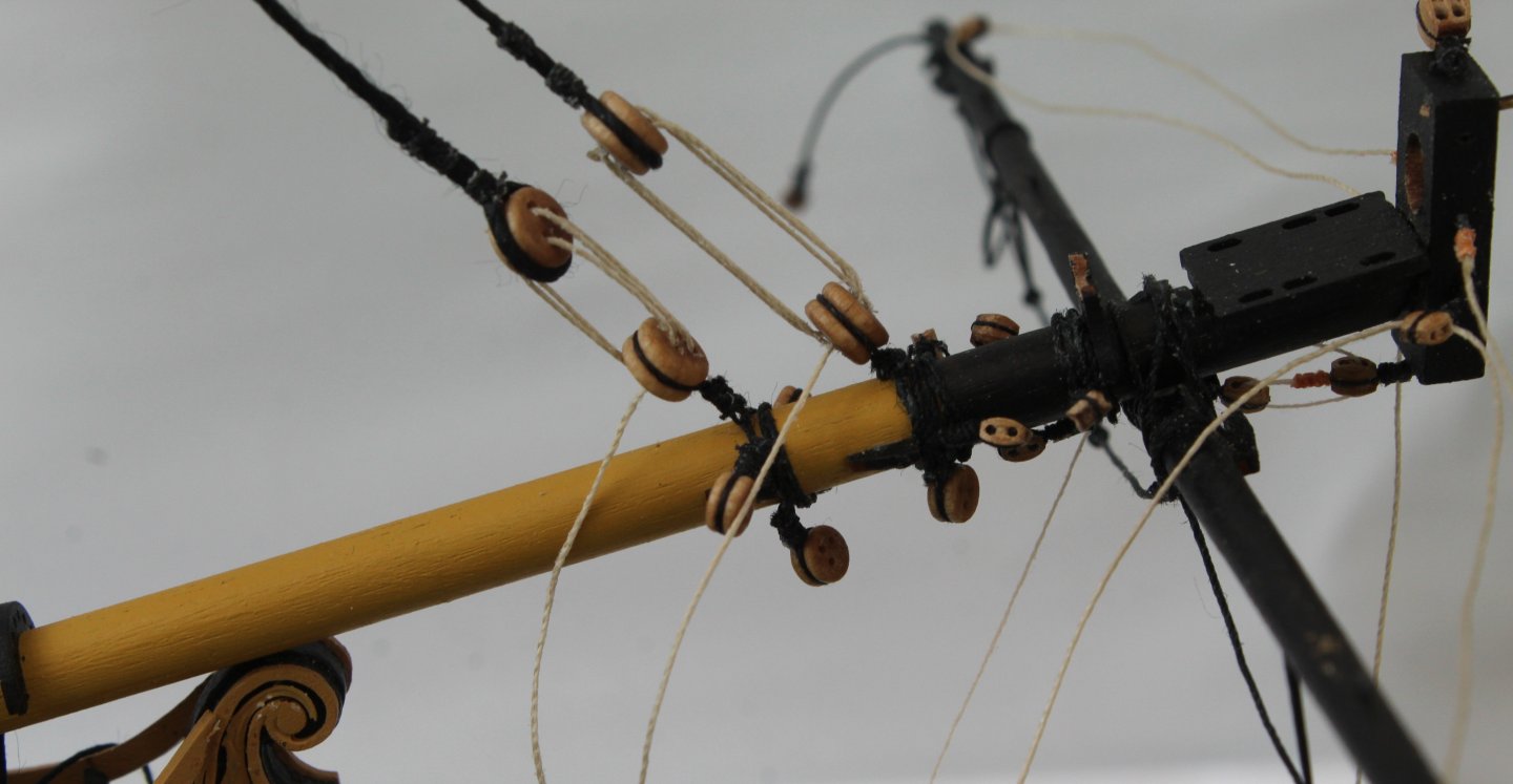
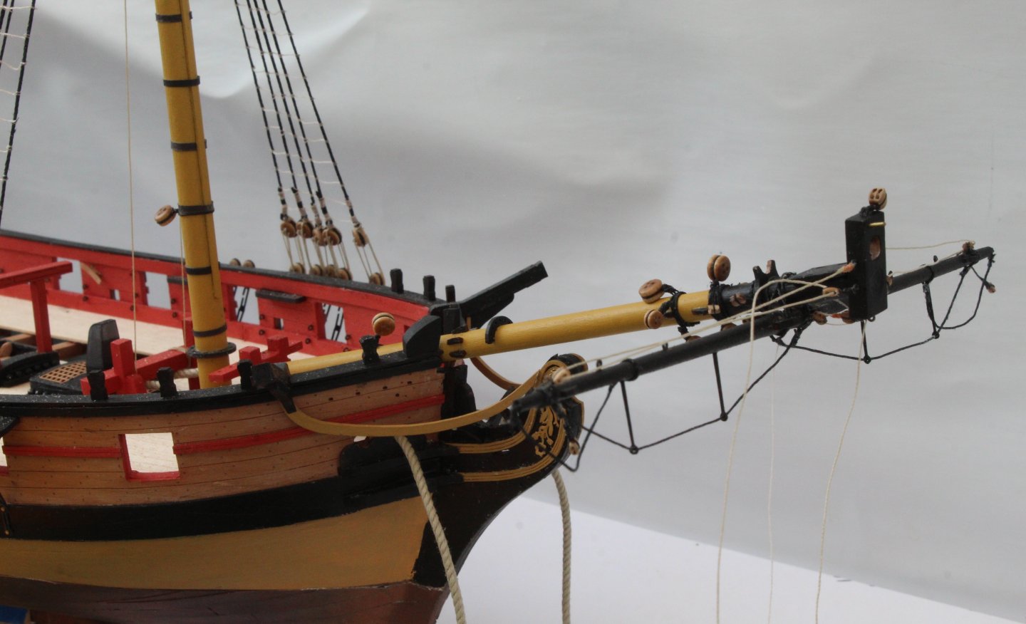
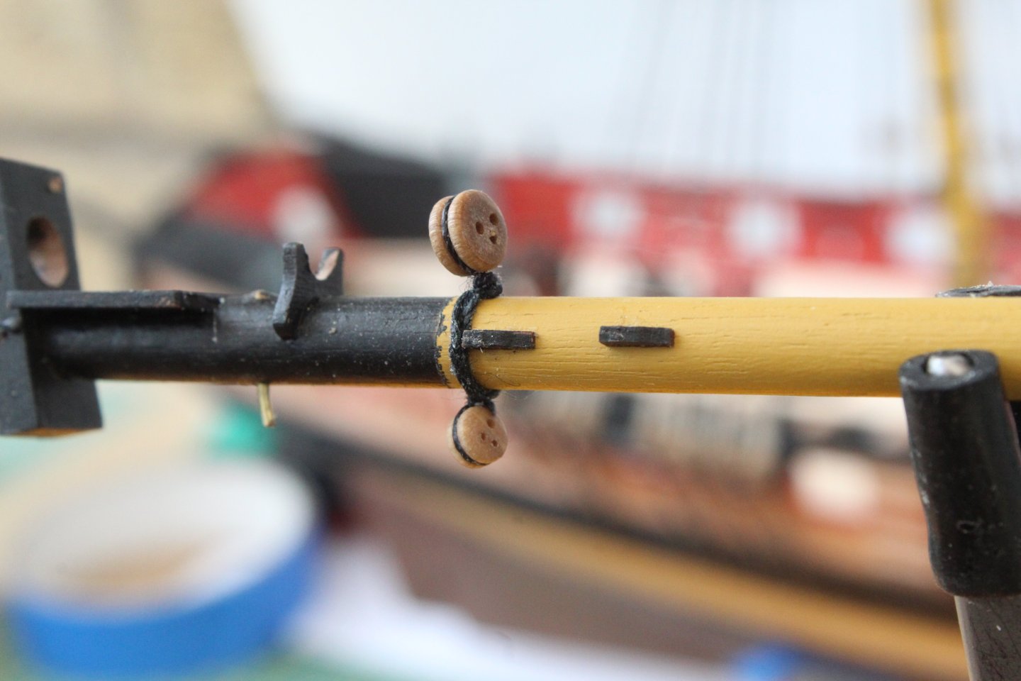
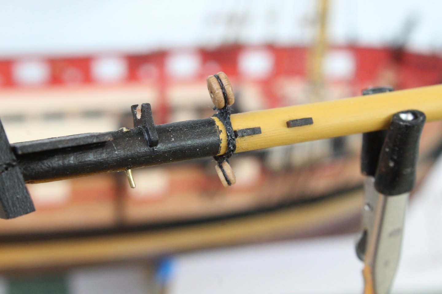
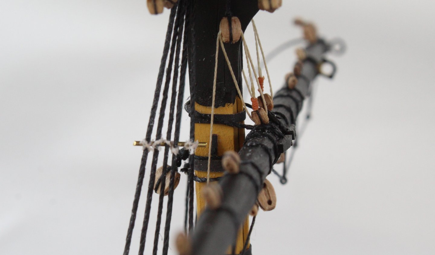
Work has continued on the bowsprit. As can be seen in the photo below I have added all the deadeyes and blocks, using the method detailed in my previous post. I then decided to add the spritsail yard prior to installation of the bowsprit to the Harpy. The spritsail lifts have been rigged and will be belayed once the bowsprit has been installed. The bow sprit was then installed. Next it was time to add the gammoning. To do this a thimble needs to be added to one end of the gammoning thread. As can be seen in the next set of photos this is an easy task, using the quad hands. The next set of photos shows various stages of adding the gammoning, including the tying off. Please note I did redo the start as the way I used the thimble in the first photo below was not right.


- 241 replies
-
- 11
-
-
- Vanguarrd Models
- Harpy
- (and 1 more)
-
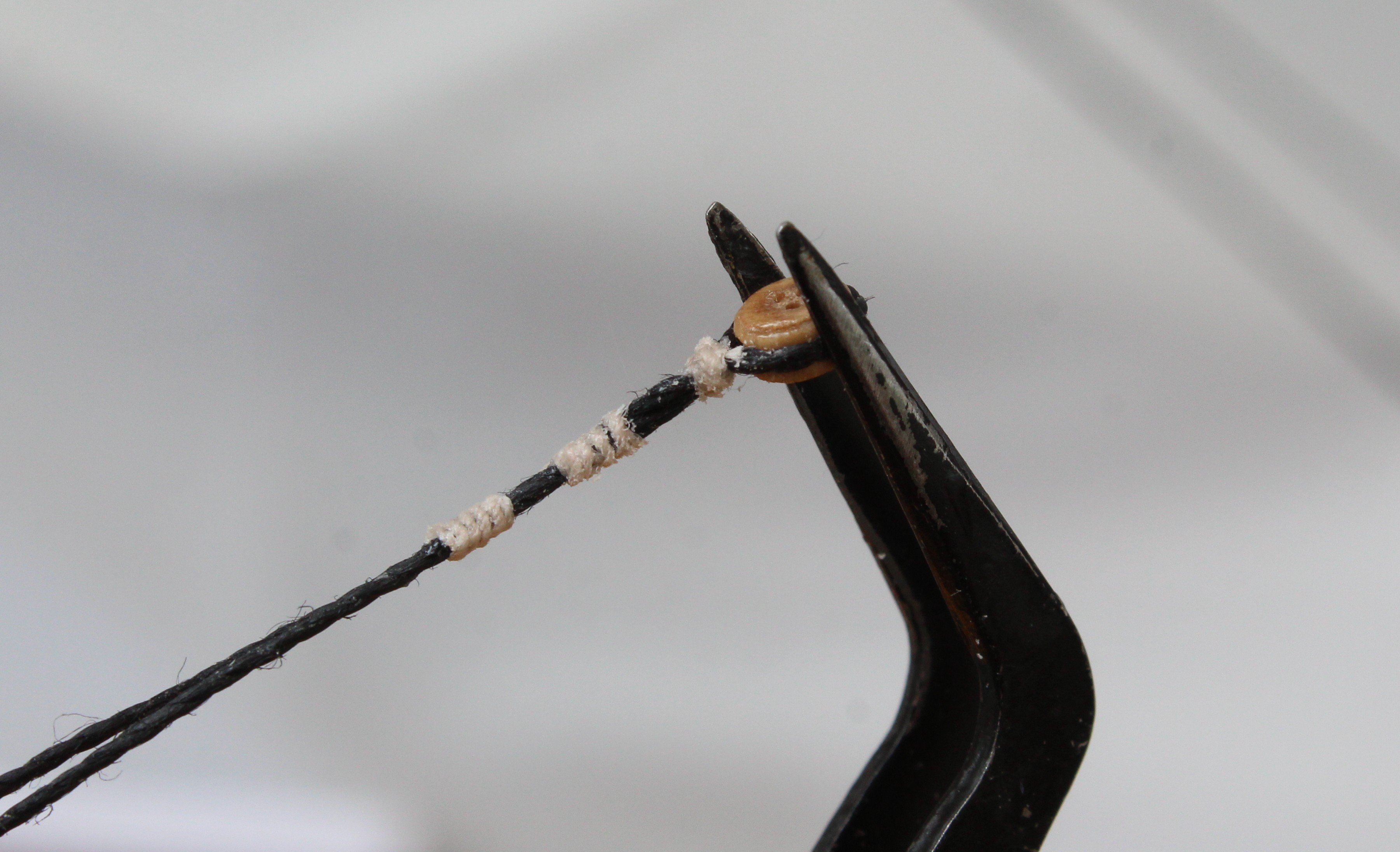
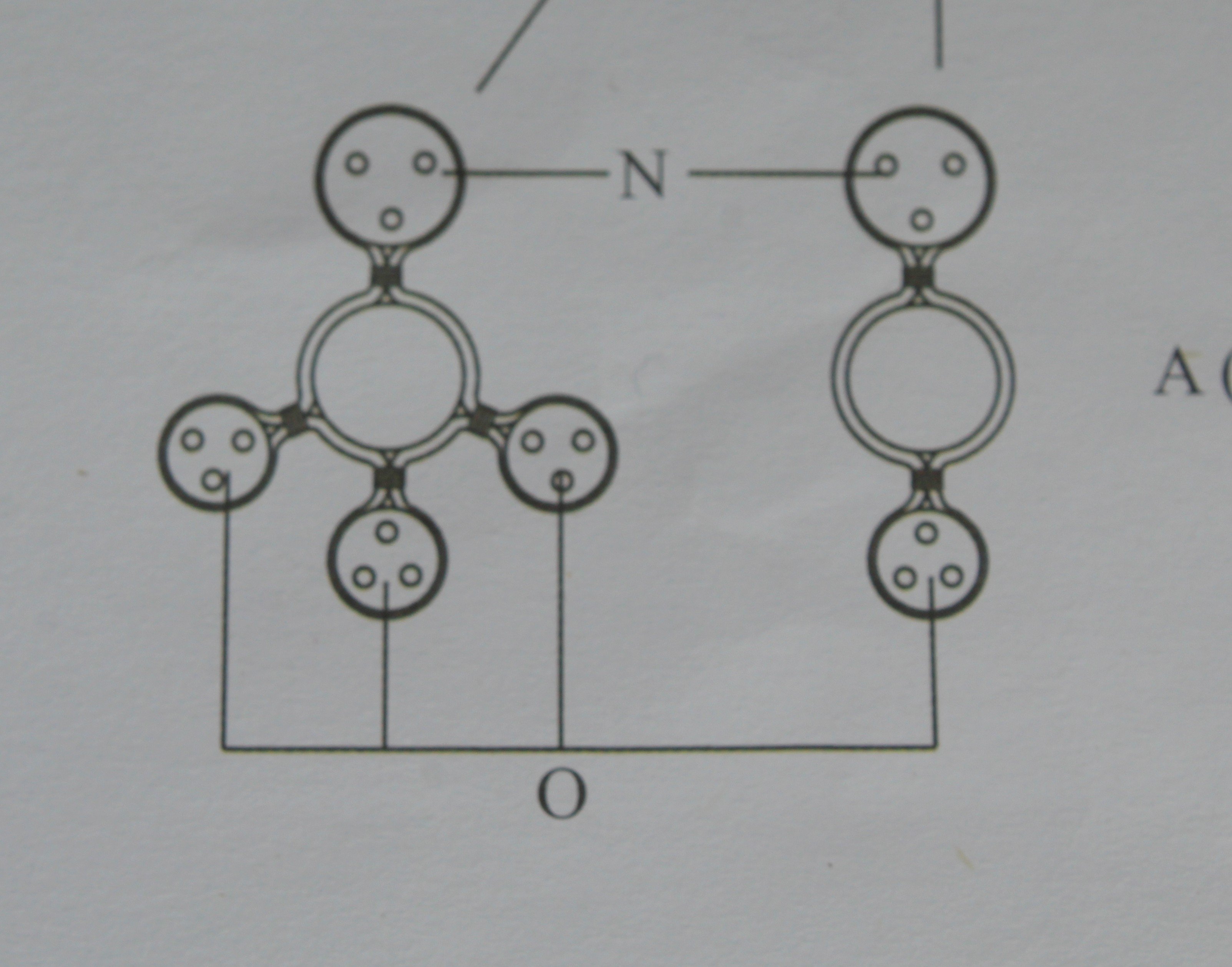
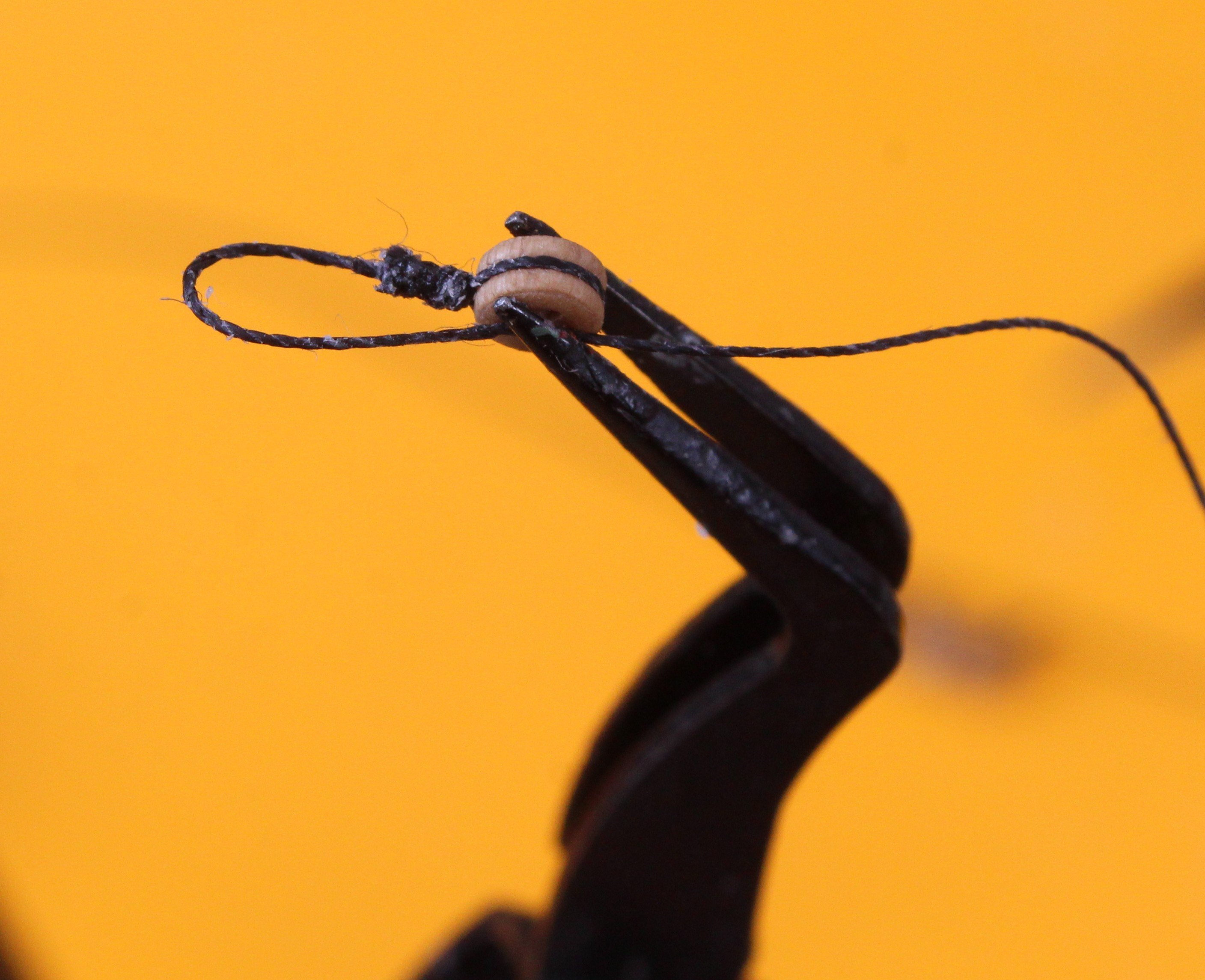
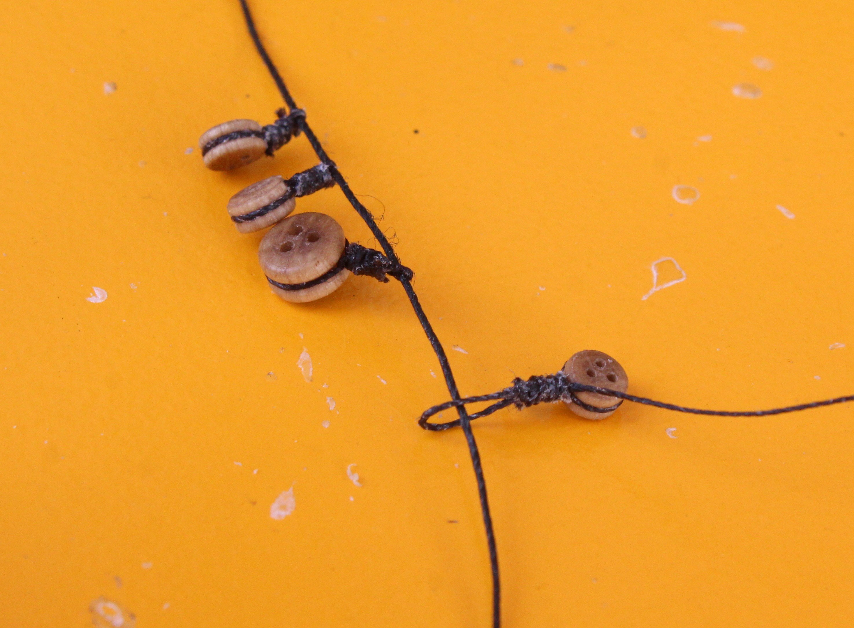
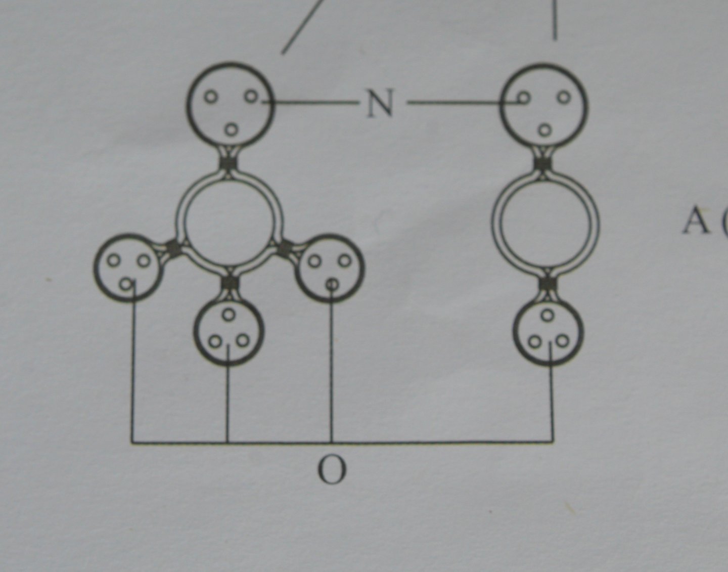
Due to the heat wave we are currently enjoying in the UK my time is the shipyard has been severely limited as I have spent much more time in the garden. When grabbing a bit of time in the shipyard I have been working on adding the various blocks and deadeyes to the bowsprit and spritsail yard. The attached plan shows the requirement with regards to the deadeye rings. I thought I would share the process I am using for adding the 4 x deadeye rings. I start by looping a length of thread around the deadeye and securing with a reef knot. The deadeye is then placed in the quad hands so the seizing can be added. In the next photo I have added the seizing to the deadeye. Next I create a loop with one end of the thread, noting the other thread end has been cut away. This is then held in the quad hands so the loop can be seized. Once the loop has been seized the loop is threaded on to another length of thread, as shown below. The loop can the be closed up by pulling the free end of thread, and the excess thread is then cut away. With all four deadeyes in place the thread can be secured to the bowsprit. The position of deadeyes can then be adjusted, as necessary.


- 241 replies
-
- 13
-
-
- Vanguarrd Models
- Harpy
- (and 1 more)
-
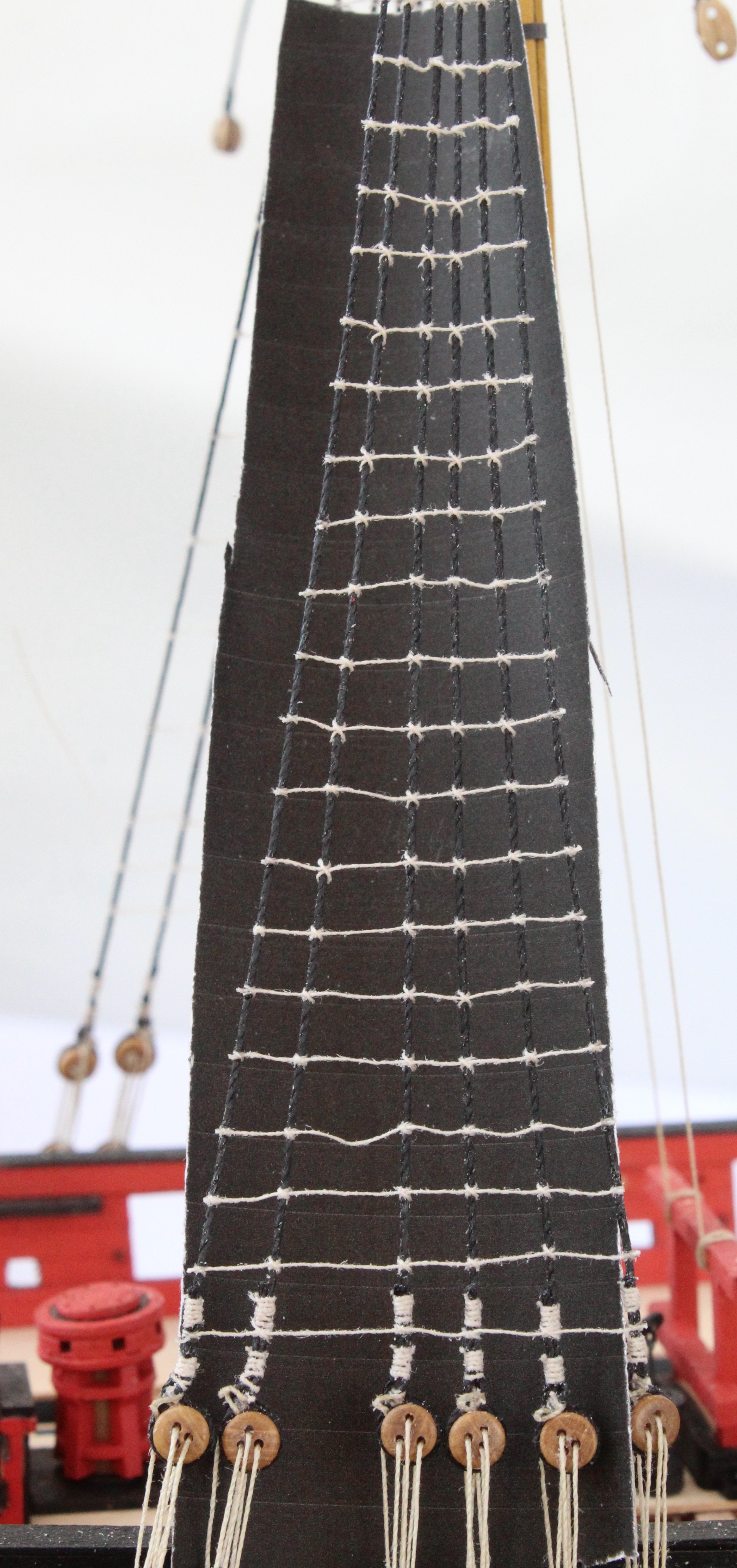
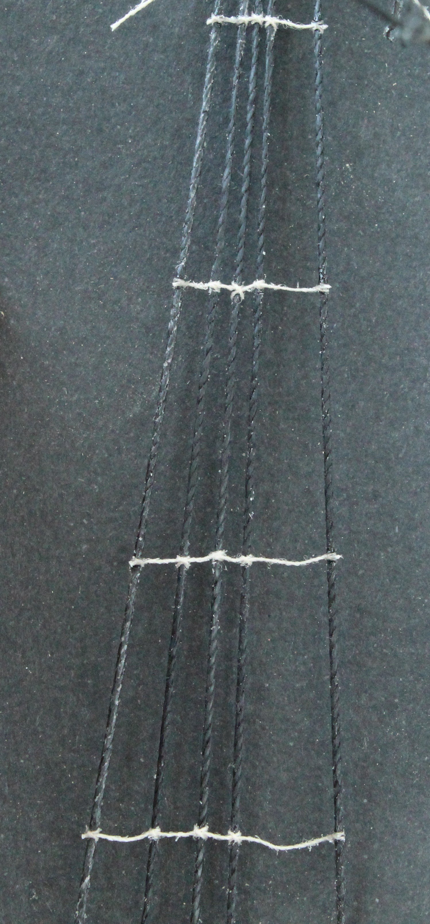
Work is progressing slowly but steadily on adding the main mast ratlines. Whilst I did like the idea of adding the yard to the mast prior to this task as it made the rigging the jeers much easier I have found the yard, when in situ, does hinder adding the upper few rows of ratlines. I started the process by adding the futtock staves, using a template to set the height equally on both sides. The copper bar was held in place using my quad hands whilst it was secured to the shroud lines. Once that was done it was simply a case of adding the ratlines. As per my earlier post I prefer to add every 5th one initially and then everyone central one between the first set of ratlines before adding the final set. I finds this method works as it prevents the hourglass effect. Also it helps to prevent having to many sagging ratlines. As can be seen in the photo below they are not perfect and I do need to adjust a couple of them but I am reasonably happy with the end result. In the next photo I have added the first two sets of ratlines on the other side and I have just started to add the final set of ratlines. I tend to leave the lowest ratlines until the end. I did record a video of adding a set of ratlines, which uploaded to YouTube YouTube Video Link If you look at the video please note that a) It was very difficult to set up the camera to record this process, in this instance the camera need to be pointed upward a bit more. b) I started by passing the ratine thread through a block of beeswax, but this bit is out of focus c) I then make a series of clove hotch knots, as each clove hitch knot is made I check it position with the template and adjust as necessary d) I am also checking the vertical alignment of the shroud lines with the marked lines on the template.

- 241 replies
-
- 9
-
-
- Vanguarrd Models
- Harpy
- (and 1 more)
-
Hi Ross If you look at my previous post you will see how I have marked the ratline template with 1, 2 and 3. I will add all the 1's (every 5th one) first as I have found this helps prevent the dreaded hourglass shroud shape. This is because the vertical slants can be set with just a few ratlines added. Once that is done the infill ratlines can be added Once I haved added all the 1's I will add all the 2's which are spaced evenly between the 1's. Finally I will add all the 3's. As you will note my template has both horizontal and vertical guide lines. However sometimes I do find it necessary to redo some of the ratlines. Hope that answers your question
- 241 replies
-
- 7
-
-

-
- Vanguarrd Models
- Harpy
- (and 1 more)
-
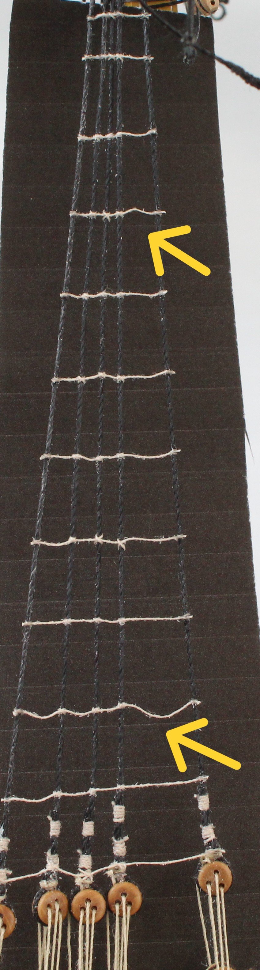
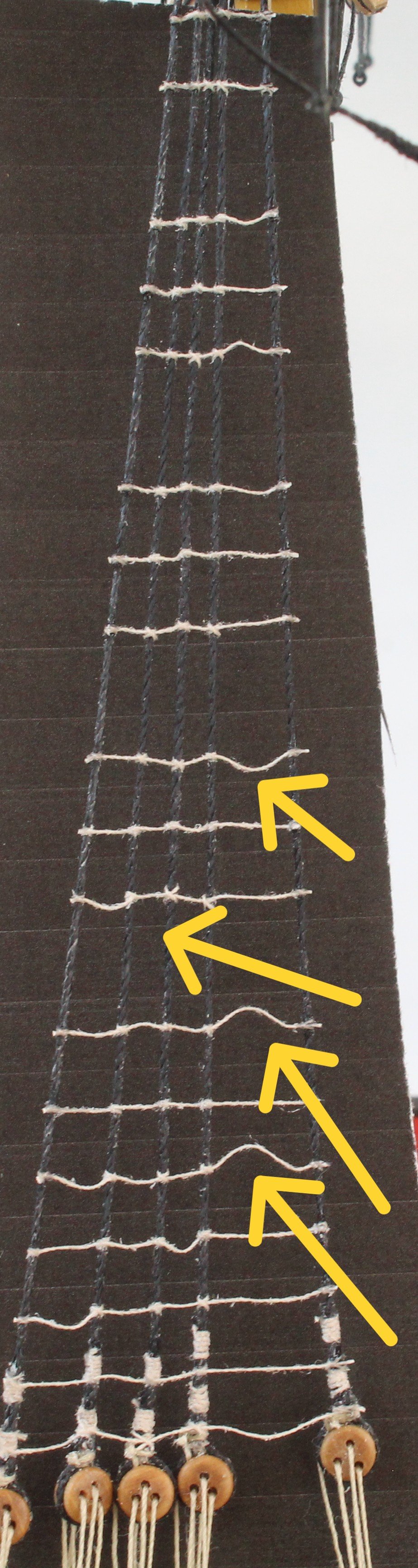
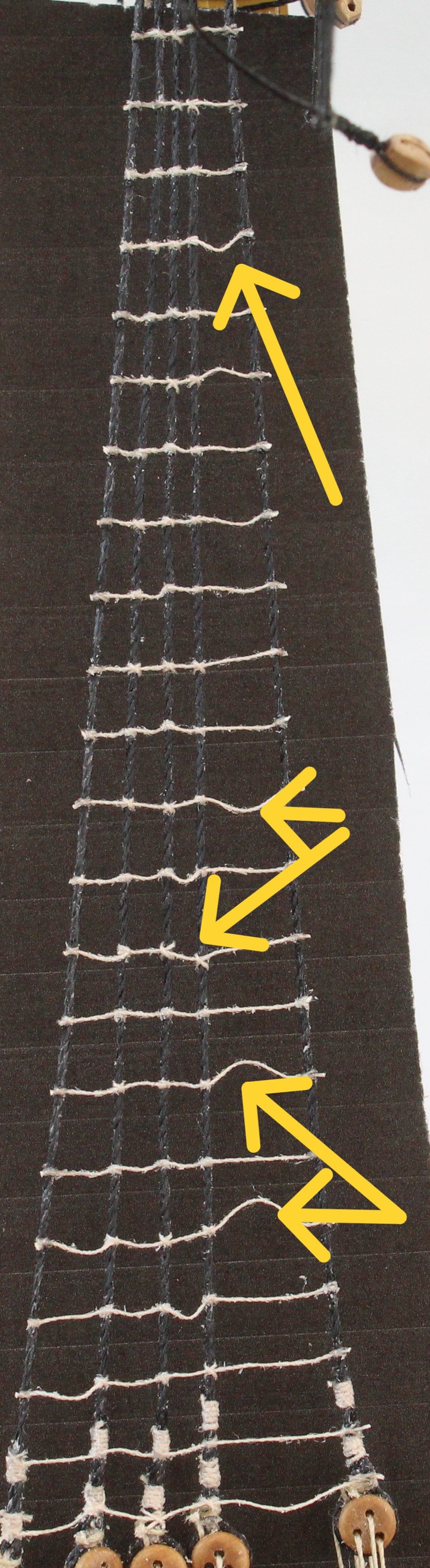
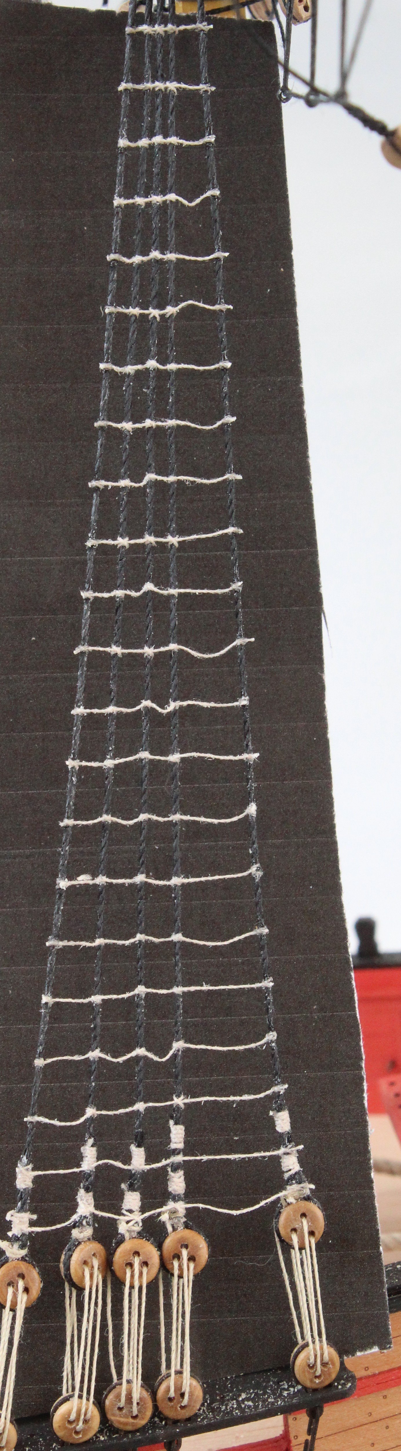
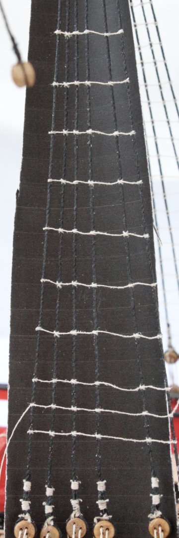
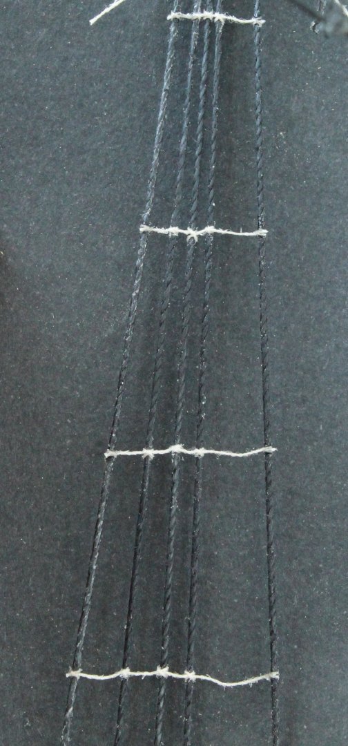
Starting to add the first ratlines, as mentioned in my last post I am adding every 5th one to start with. When I had completed adding every 5th ratline I did then the next ratline above the top 5th ratline. As I started to add the next set of ratlines I noted that I may need to revisit some of the one previously added, as can be seen below. With the next set of ratlines added I am still noting which ones may need to be redone. Moving on to adding the next set, as can be seen below With the ratlines completed I now need to decide which ones do not pass muster and will need to be redone. Reworked some of the ratlines and they look much better, as can be seen in the photo below. Some could still be redone but as far as I am concerned they look OK.


- 241 replies
-
- 7
-
-
- Vanguarrd Models
- Harpy
- (and 1 more)
-
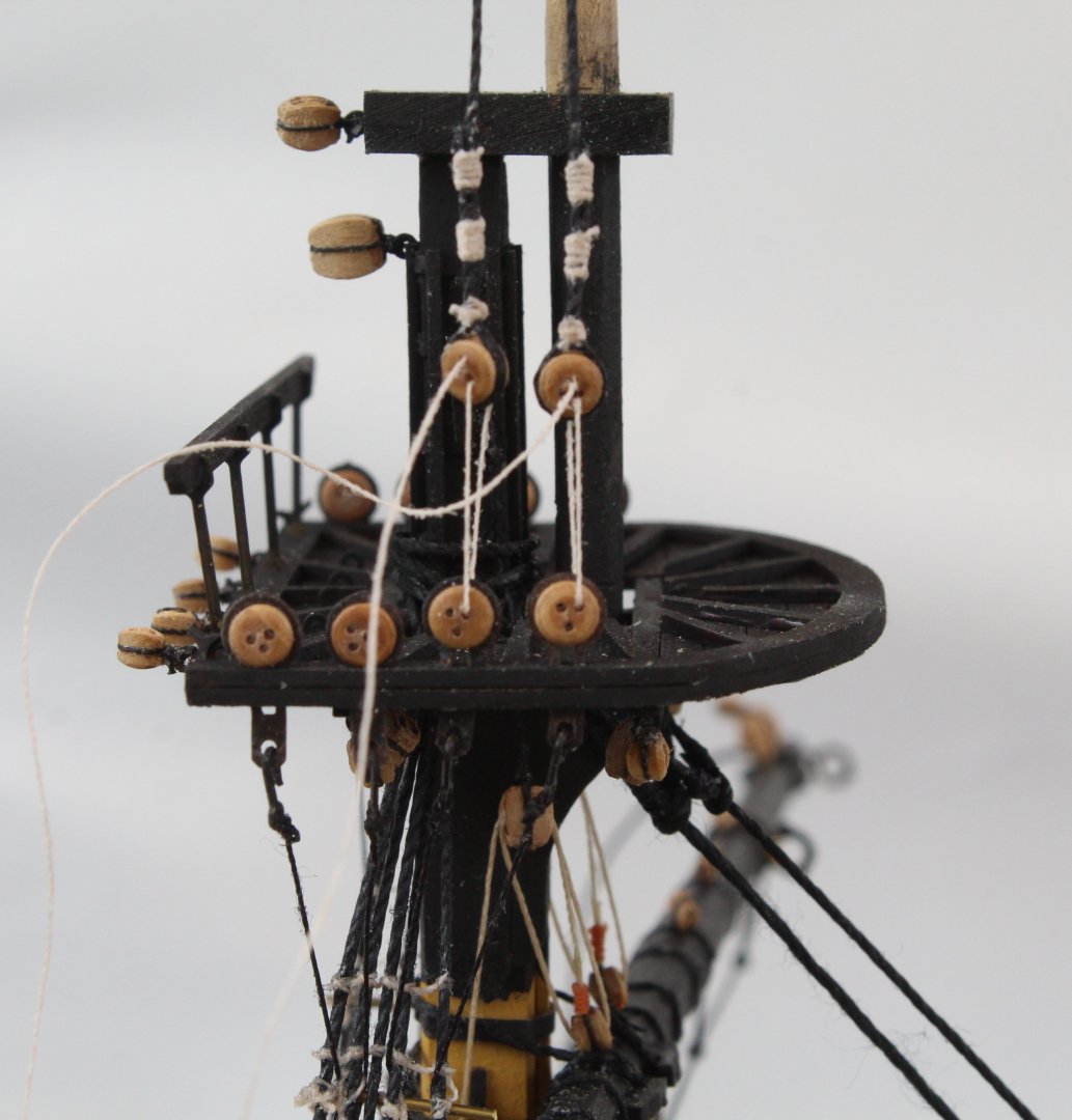
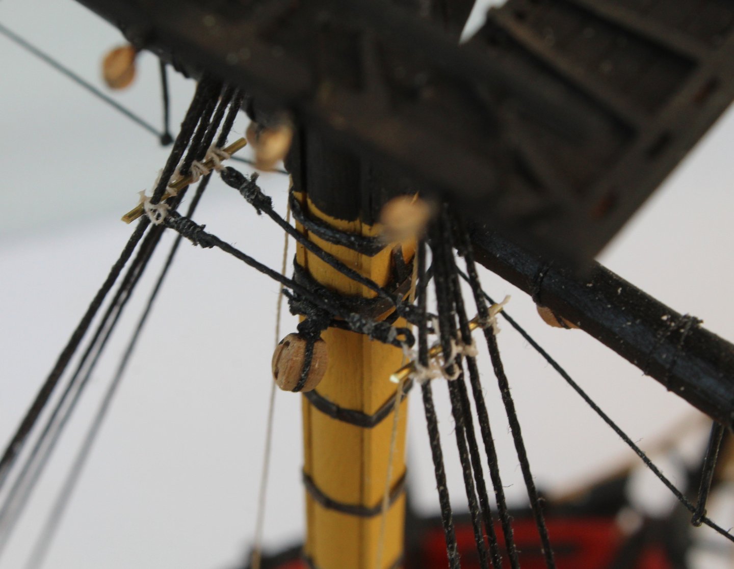
Now that I am finally happy with the how the foremast shroud lines are looking with the deadeyes the lanyards were tied off. In preparation for adding the ratlines I printed out a template. I angled the bottom edge of the template so the ratlines will be level, when fitted. Before adding the ratlines I decided to add the futtock staves. I used my quad hands to hold the copper bar in place, as shown below. I marked off the position of the futtock stave on the template and then adjusted the position of the copper bar to the required height. It was then a case of adding some seizing. In the next photo I have secured to futtock staff to three of the shroud lines. In the next photo both the futtock staves have been added. By marking the position of the futtock stave on the templates they both should be set to the same height. Next I made the catharpins. These are simply a length of thread with loops on each end. Seizing thread was then added to the loops. It was then a case of securing the catharpins to the futtock staves. With the template in place I did make a start adding the ratlines. As per my normal method I marked the order of fitting on the template. I will add every 5th one starting with the 1's. Once that is done I will add all the 2's and then all the 3's. I have also added some vertical guidelines.
- 241 replies
-
- 12
-
-
- Vanguarrd Models
- Harpy
- (and 1 more)
-
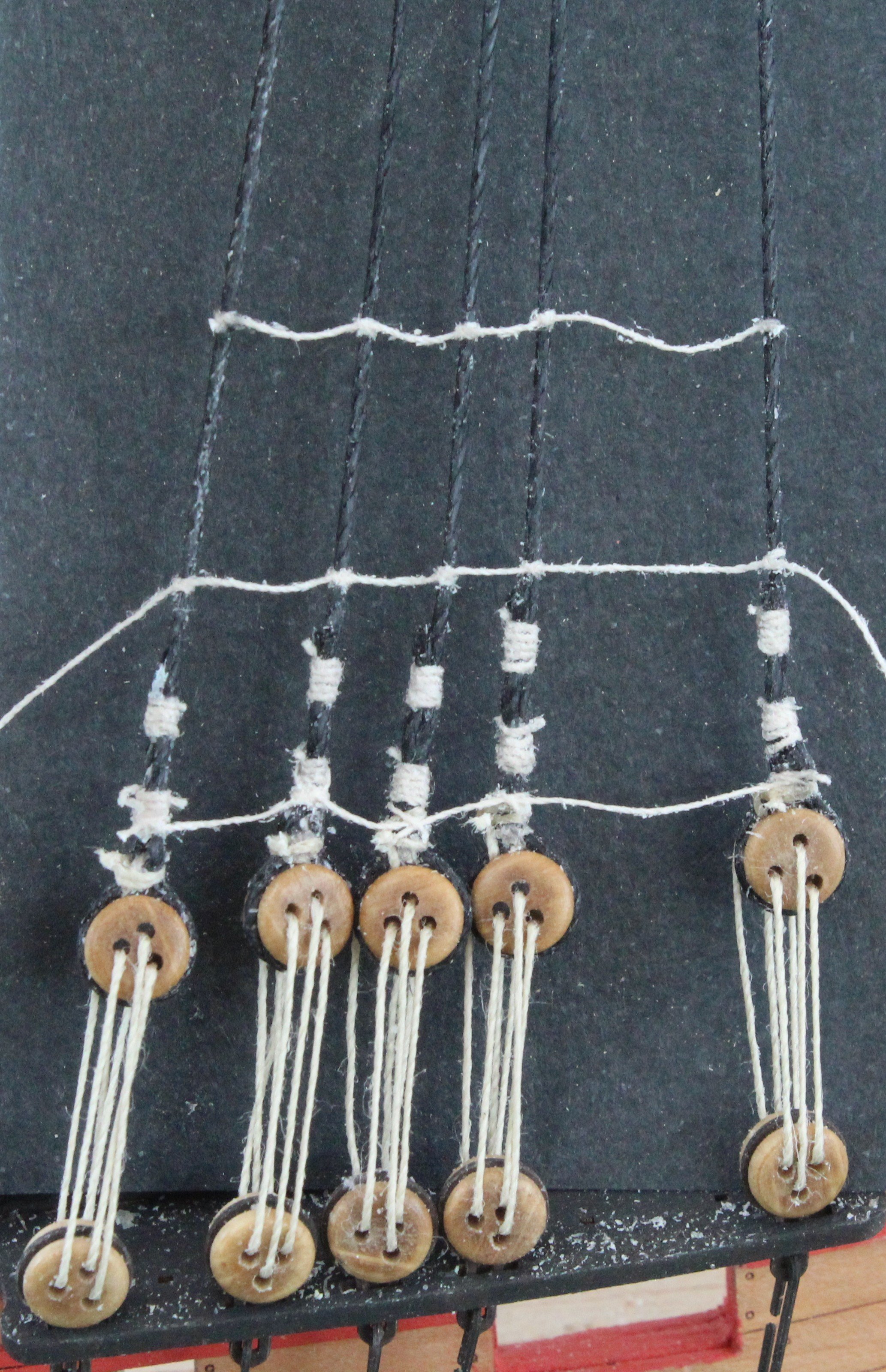
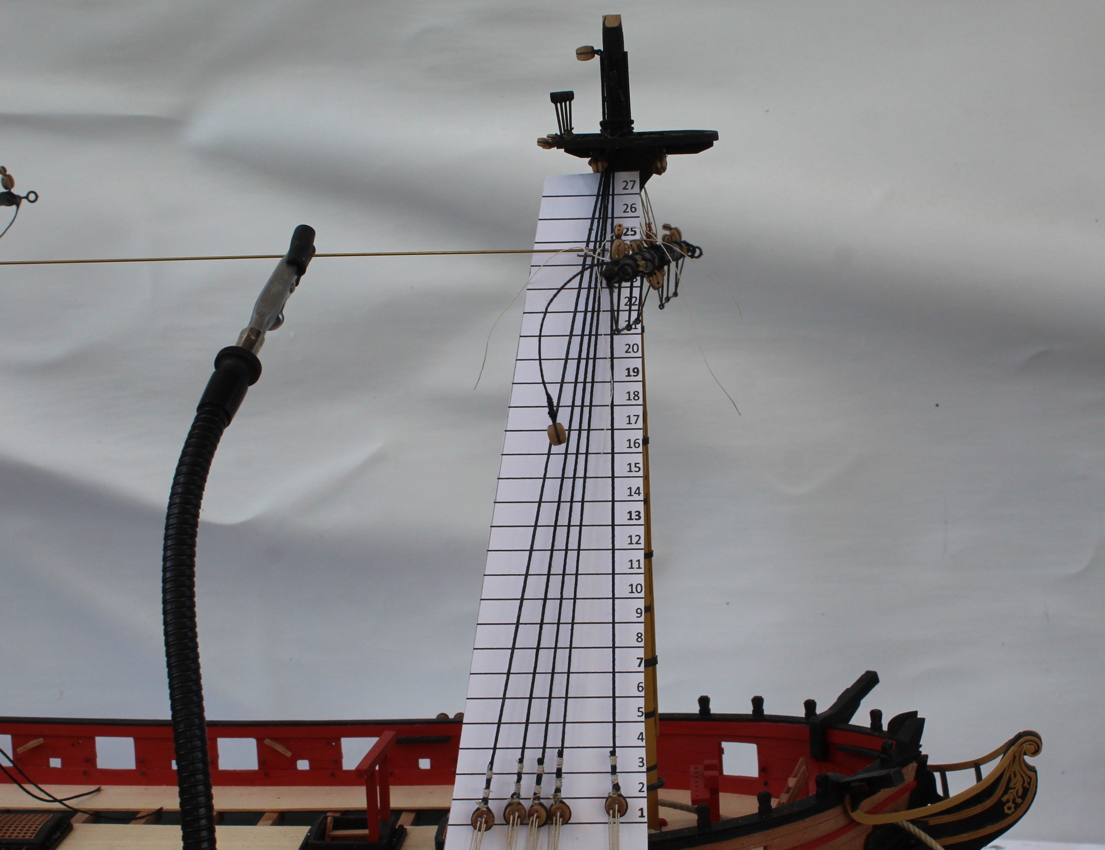
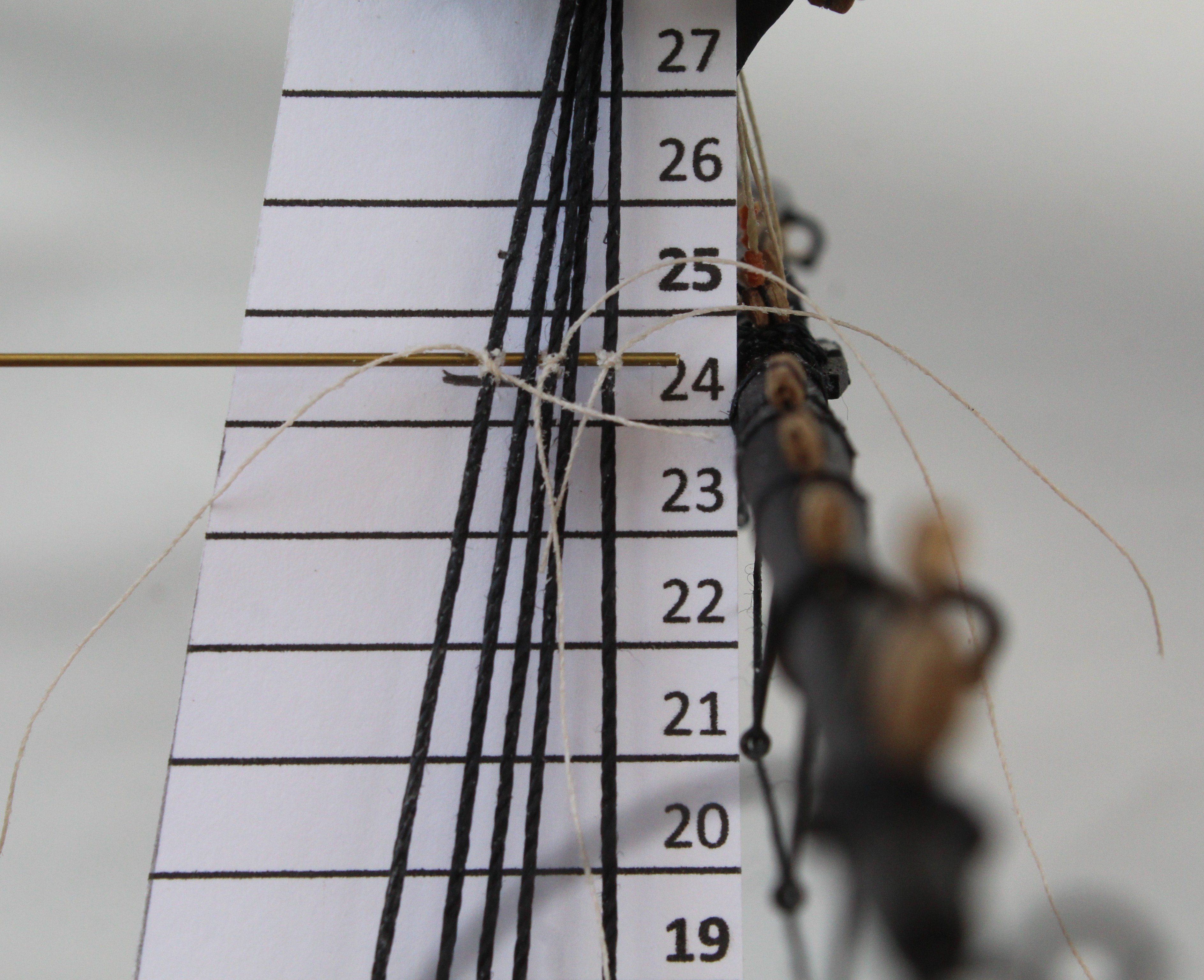
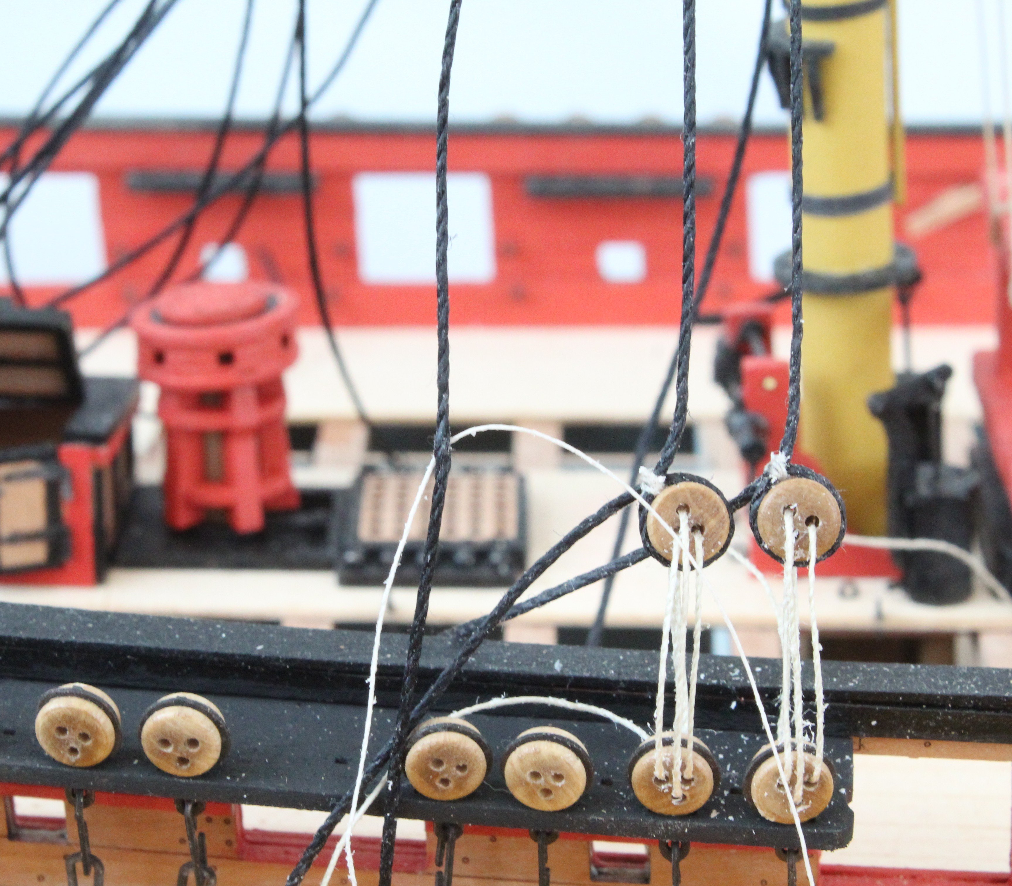
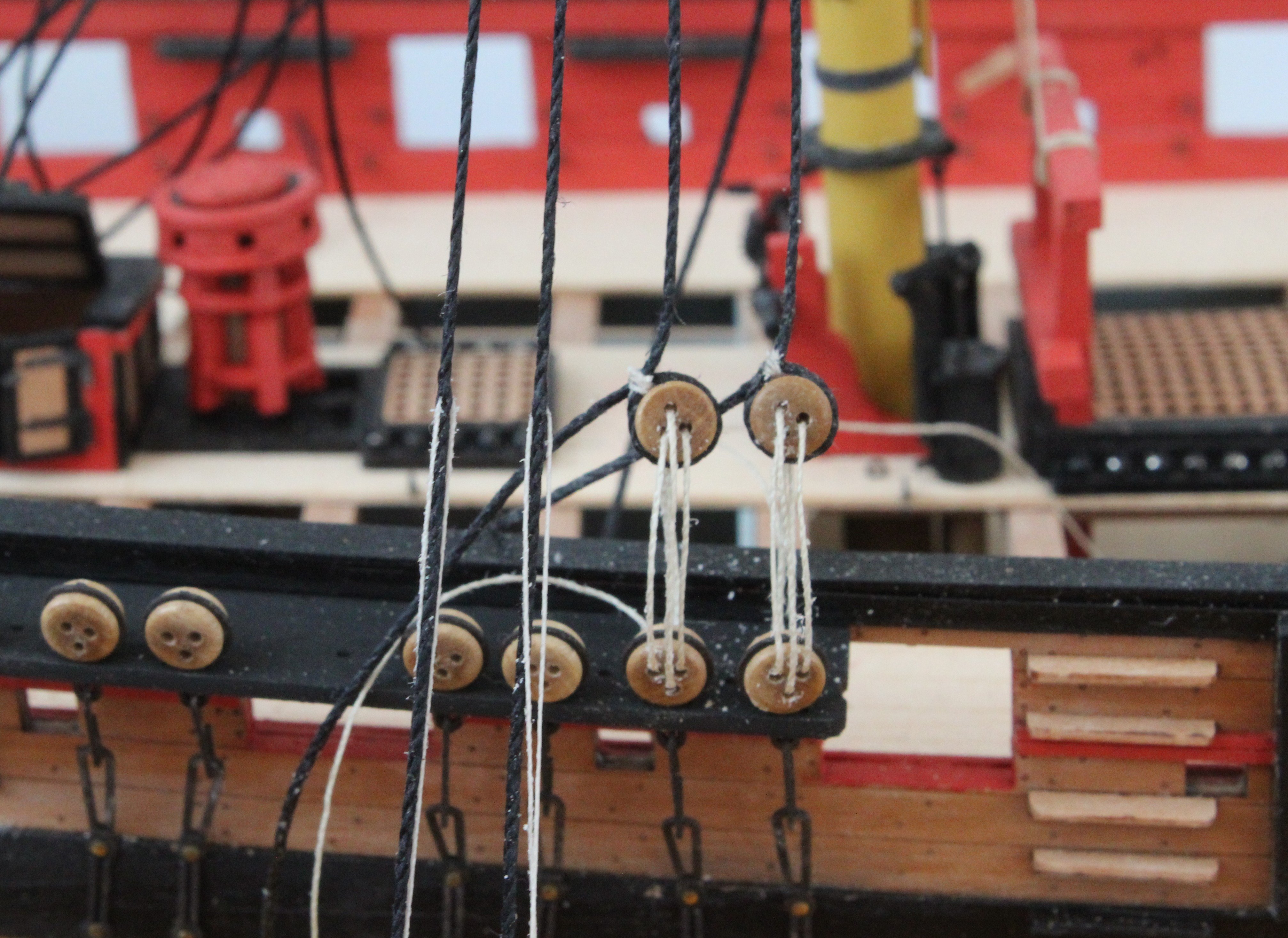
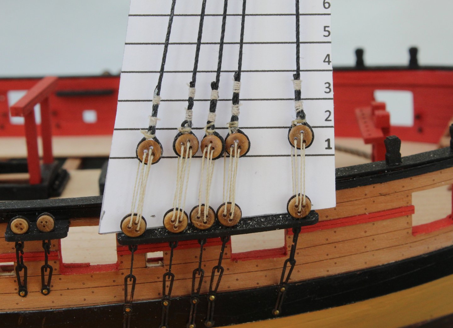
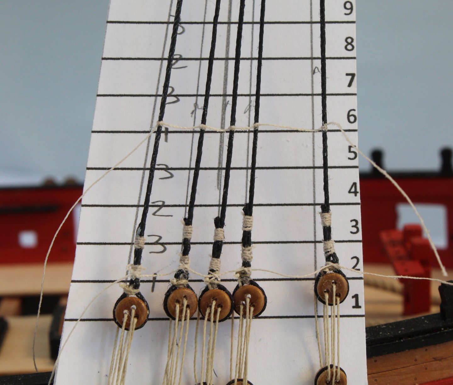
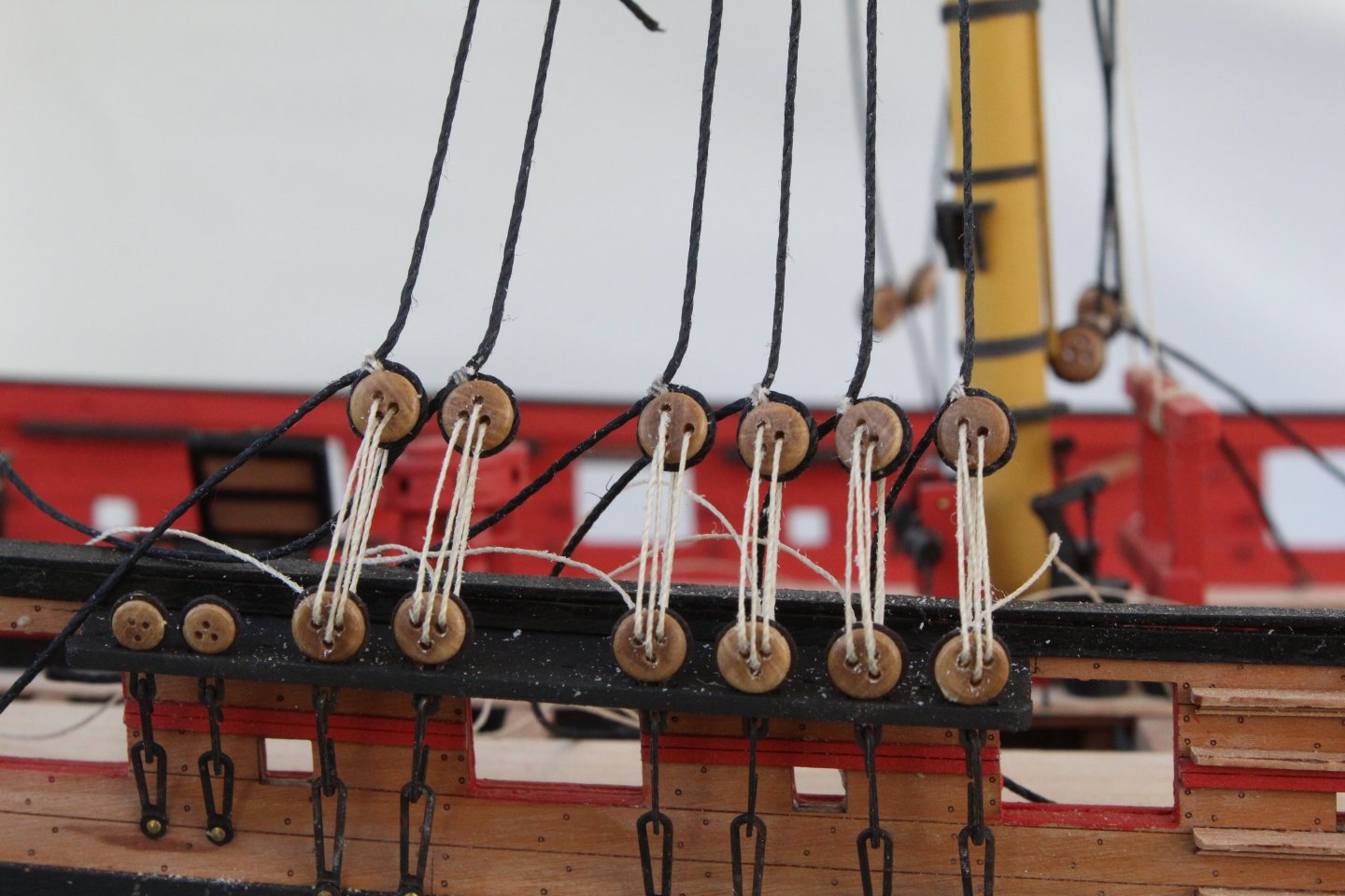
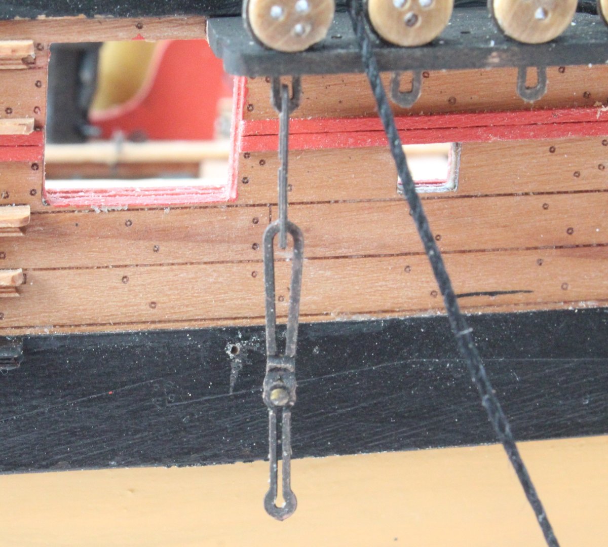
Following on from my last post I thought I would detail how I went about resetting the distance between the channel and shroud deadeyes. I started by marking both the current position of the top of the shroud deadeye and the required height of 20mmm on a template, as shown below. Once all the old seizing threads were removed, with the exception of the deadeye positioning thread, a new positioning thread was added using the marked template as a guide. This is shown in the next photo. A new deadeye loop was formed and held in position using the quad hands. The deadeye loop seizing was then added using three cross over knots, as shown in the next two photos. The formed loop was then closed up around the deadeye and the excess thread trimmed. A touch of ca glue was used to secure the loop seizing. The shroud line was then placed in the quad hands so the remaining seizing could be added, using a series of cross over knots, 5 cross over knots per side. The shroud line was then test fitted and the distance checked. As can be seen below the distance now seems to be about right.


- 241 replies
-
- 7
-
-
- Vanguarrd Models
- Harpy
- (and 1 more)
-
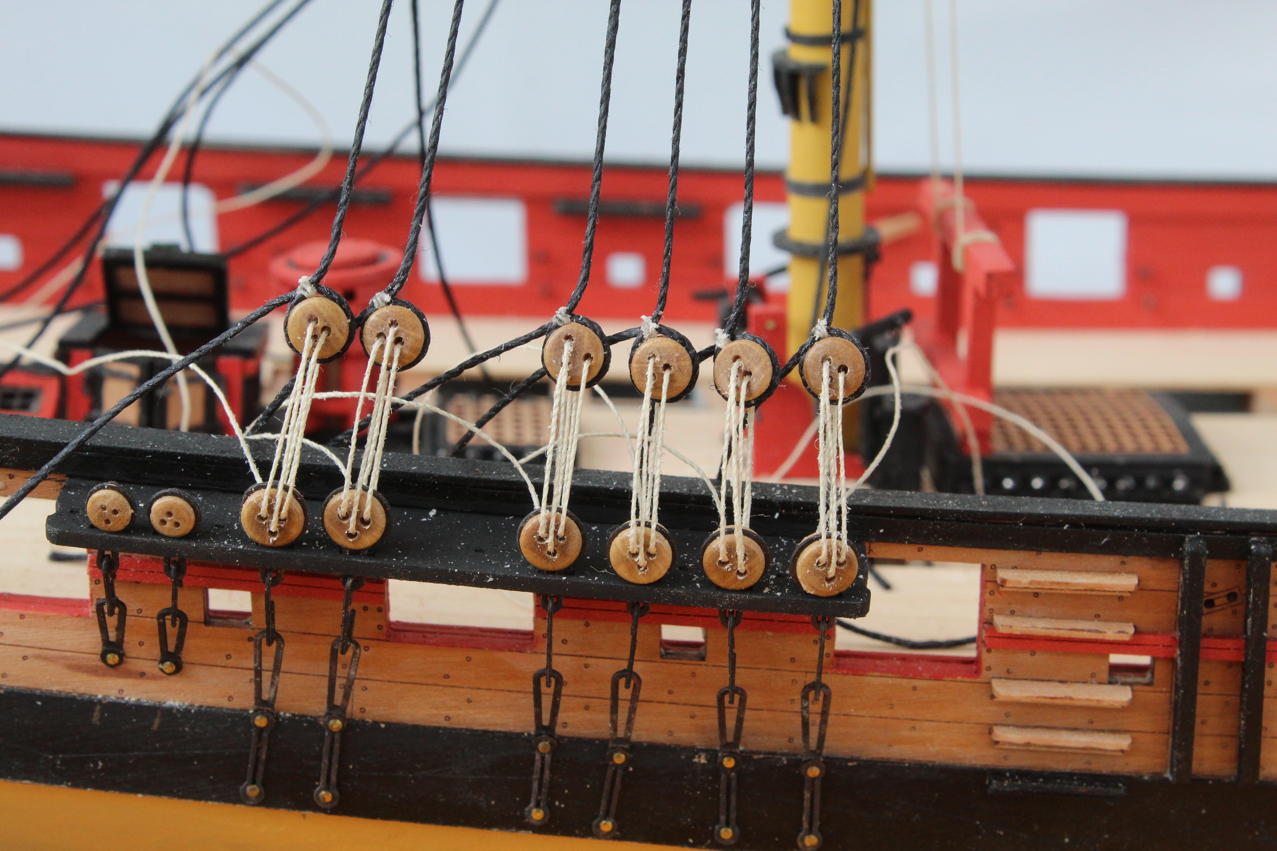
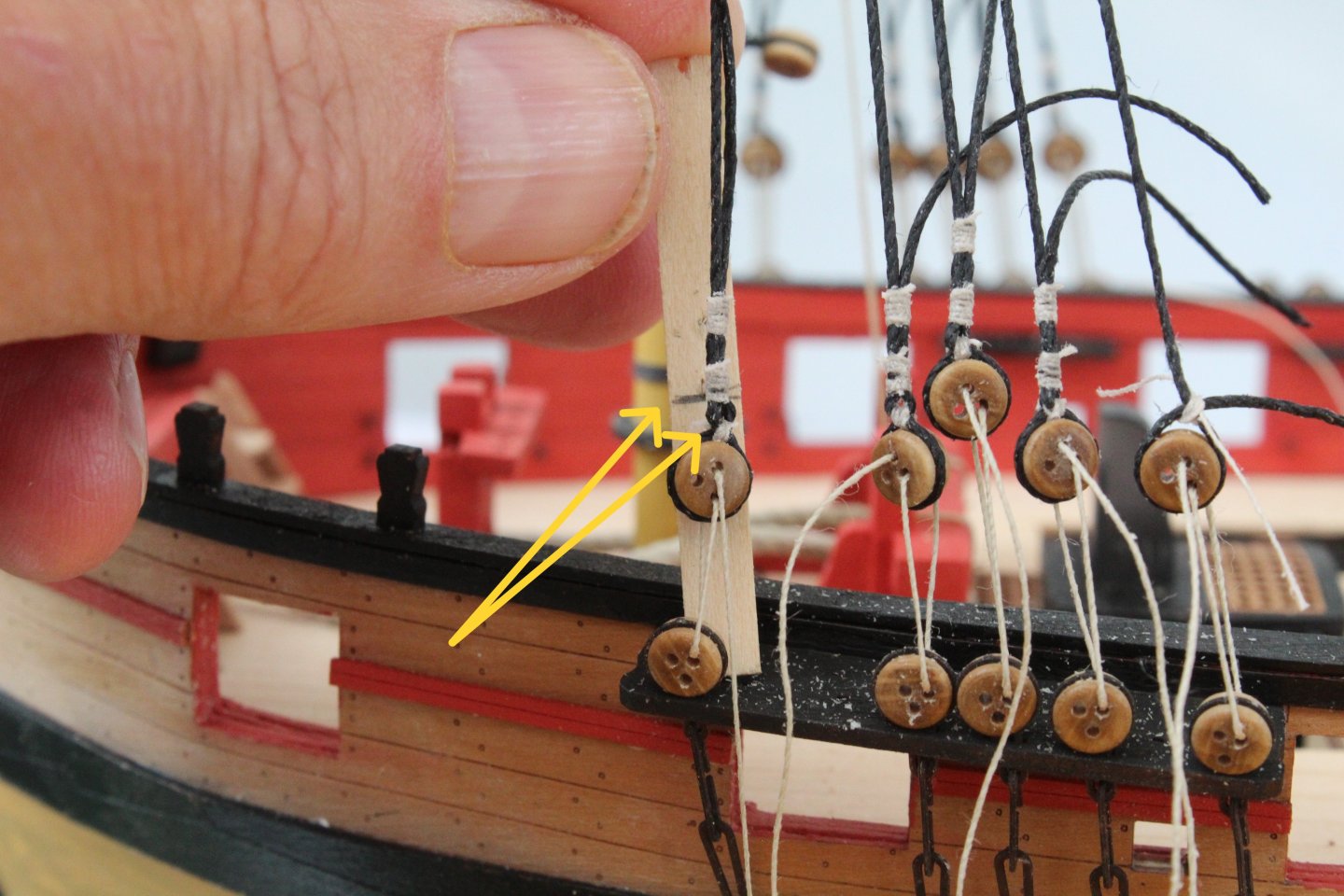
In my last post I noted that the gap between the channel and shroud deadeyes need to be redone. After reworking the right-hand foremast side I was eventually reasonably happy. The shroud deadeyes are not perfectly level which each other, which is true on the real ships, but they are close enough to satisfy me and then can all be adjusted slightly when I tie of the lanyards. The white powder on the channel is some excess beeswax which I will clean up. Moving on to the left-hand side after an initial check I was happy with the positioning of the deadeyes in the shroud lines. However, after adding the seizing it was clear I had made an error, as can be seen in the photo below. Stupidly I had managed to mix up the first two pairs shroud lines when I was positioning the deadeyes and when, after adding the seizing, I used the correct pairs the mistake became very apparent. I am using a template to check the position of each deadeye, the pencil mark is set to 20mm which is where the top of the shroud deadeye should be positioned. The only one that is correct is the final shroud line as that one line that did not get mixed up. In the photo below the shroud deadeye is less than the 20mm spacing by a couple of mm. Thankfully it is an easy task to release the shroud deadeyes and to then remove the seizing and fingers crossed I will get it sorted on my next attempt.


- 241 replies
-
- 12
-
-
- Vanguarrd Models
- Harpy
- (and 1 more)
-
A great set of photos which shows your excellent skills in building these kits.
- 332 replies
-
- 2
-
-
-
- Harpy
- Vanguard Models
- (and 1 more)
-
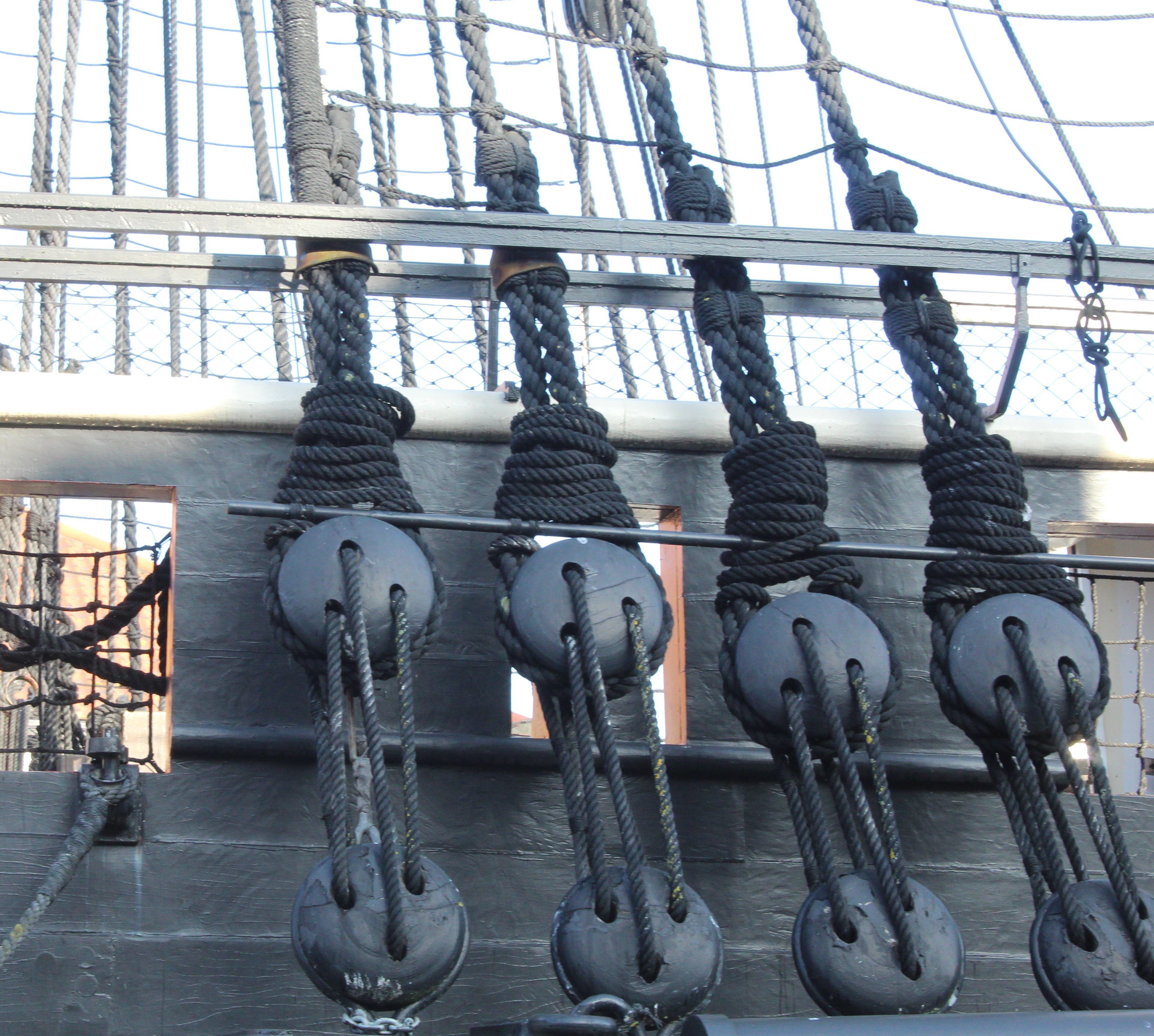
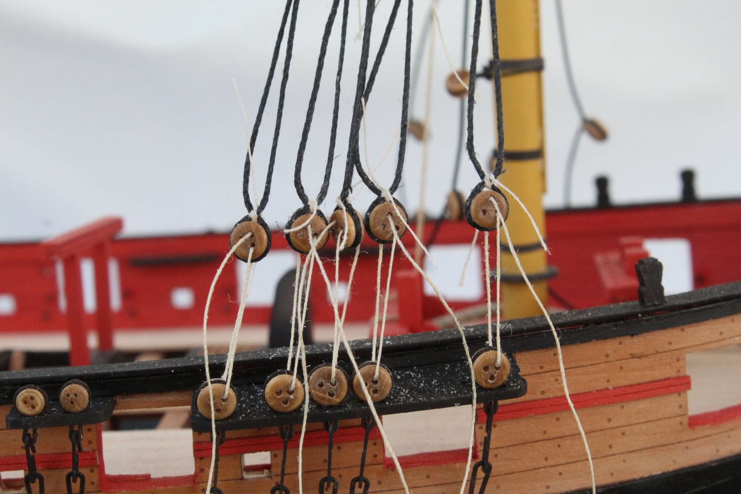
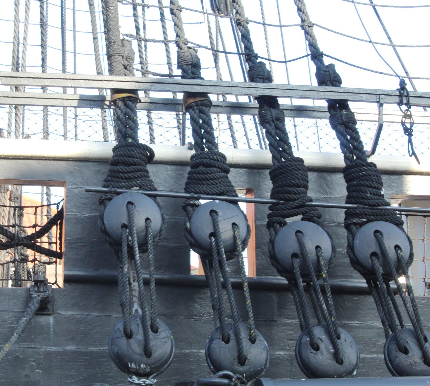
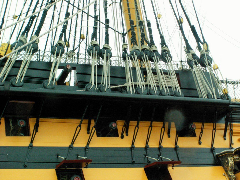
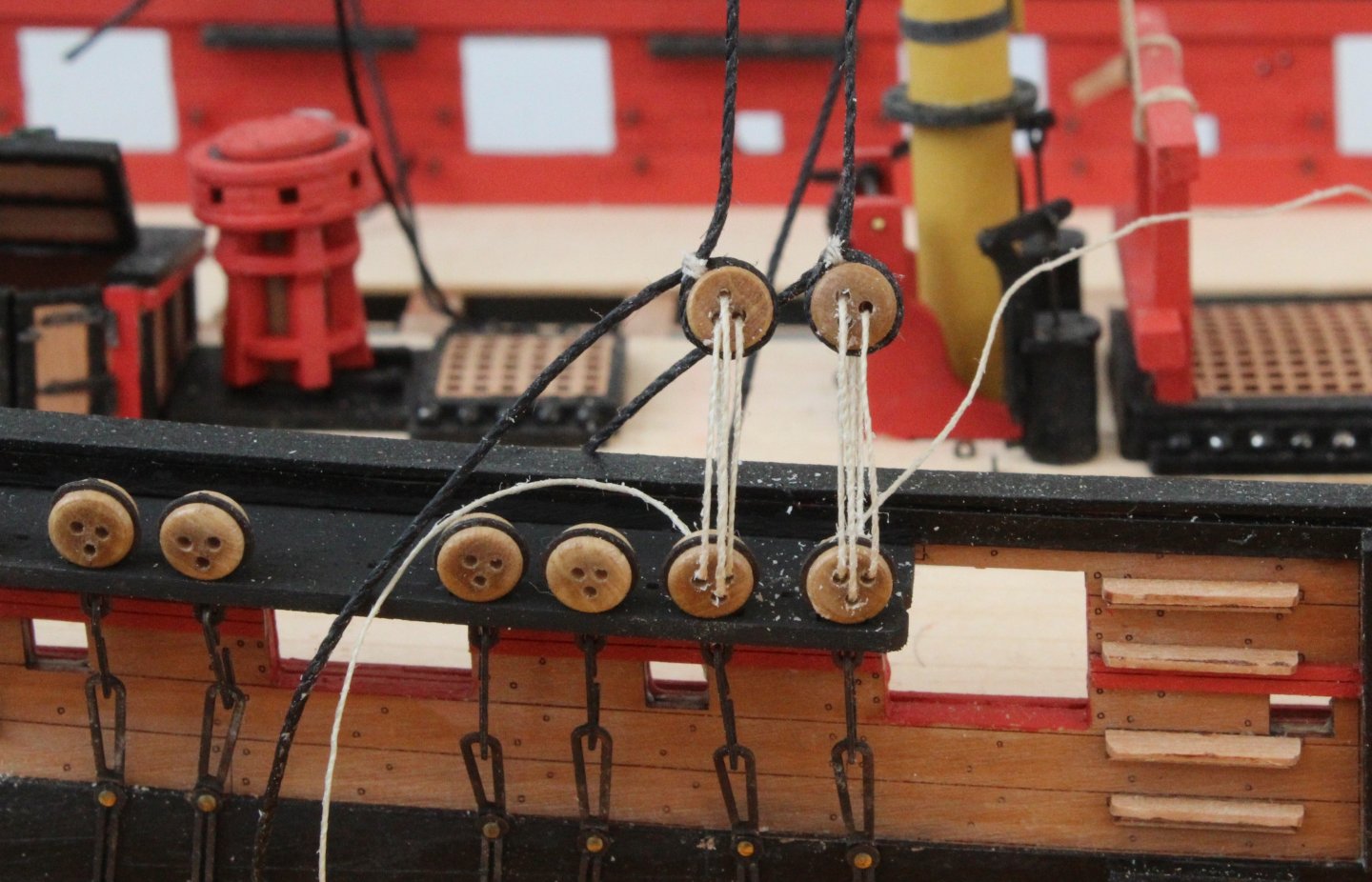
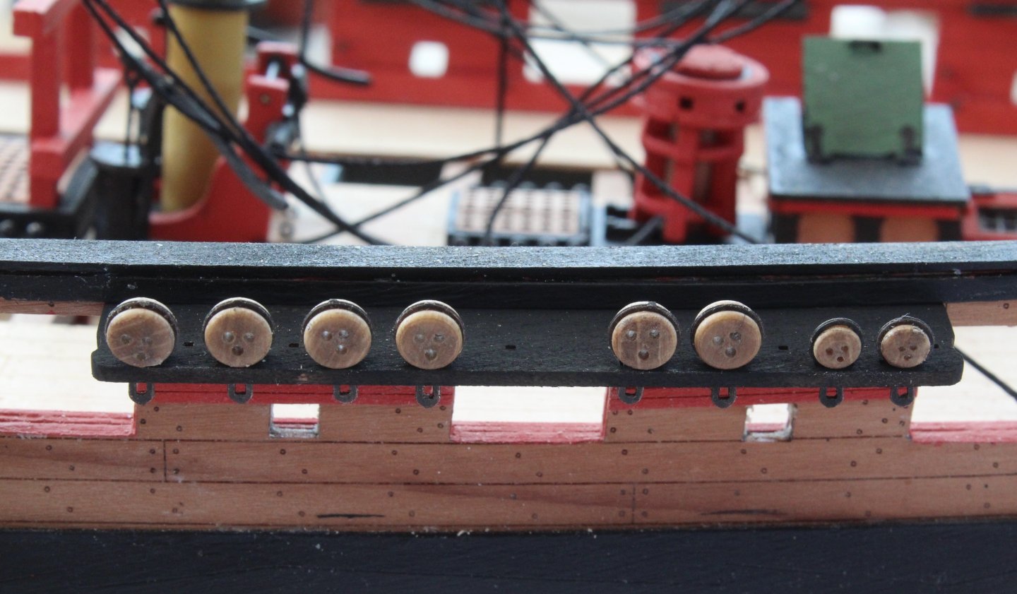
Work has stalled on the Harpy build as I am pondering the distance to set between the channel and shroud deadeyes. On my initial research it would seem the lanyard spacing between the deadeyes should be 5 times the diameter of the deadeyes, noting 4 times is also used and 3 times infrequently, this equates to 25mm, 20mm and 15mm respectively for 5mm deadeyes. On this basis I decided to set the lanyard spacing to 20mm (4 x 5mm deadeyes) on the foremast. To my eye this spacing looks very large. Looking at photos of the HMS Trincomalee and HMS Victory the lanyard spacing seems quite small. When looking at the rigging plans provided with the kit the measurements seem to be 20mm from bottom of channel deadeye to the top of the shroud deadeye and the lanyard spacing, as measured from top of channel deadeye to the bottom of the shroud deadeye, is approx 8mm. The lanyard spacing, as measured from top of channel deadeye to the bottom of the shroud deadeye, on the main mast shrouds is much more appealing to my eye but still a bit more than those shown on the rigging plans at about 13mm The foremast lanyard spacing will need to be reduced. I am currently undecided if I should reduce the overall lanyard spacing to approx 8-10mm which means I will have to redo all the shroud deadeyes. I have much to ponder over the next few days whilst my wife and I travel to Bramhall for a few days to help look after a couple of our grandkids. My current thinking is that I should remove all the shroud deadeyes so I can reset to the lanyard distance to approx 10mm, as measured from top of channel deadeye to the bottom of the shroud deadeye.
- 241 replies
-
- 10
-
-
- Vanguarrd Models
- Harpy
- (and 1 more)
-
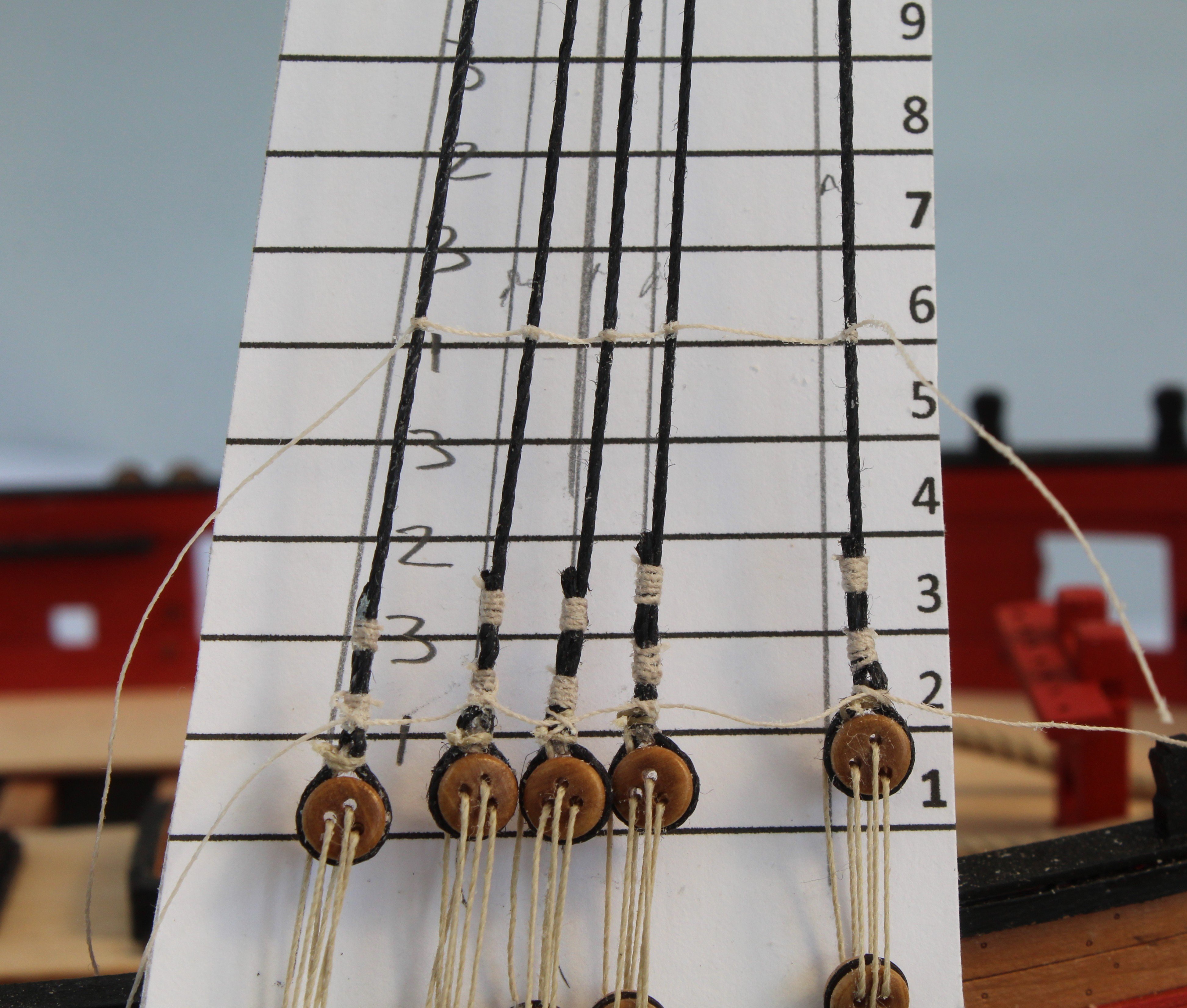
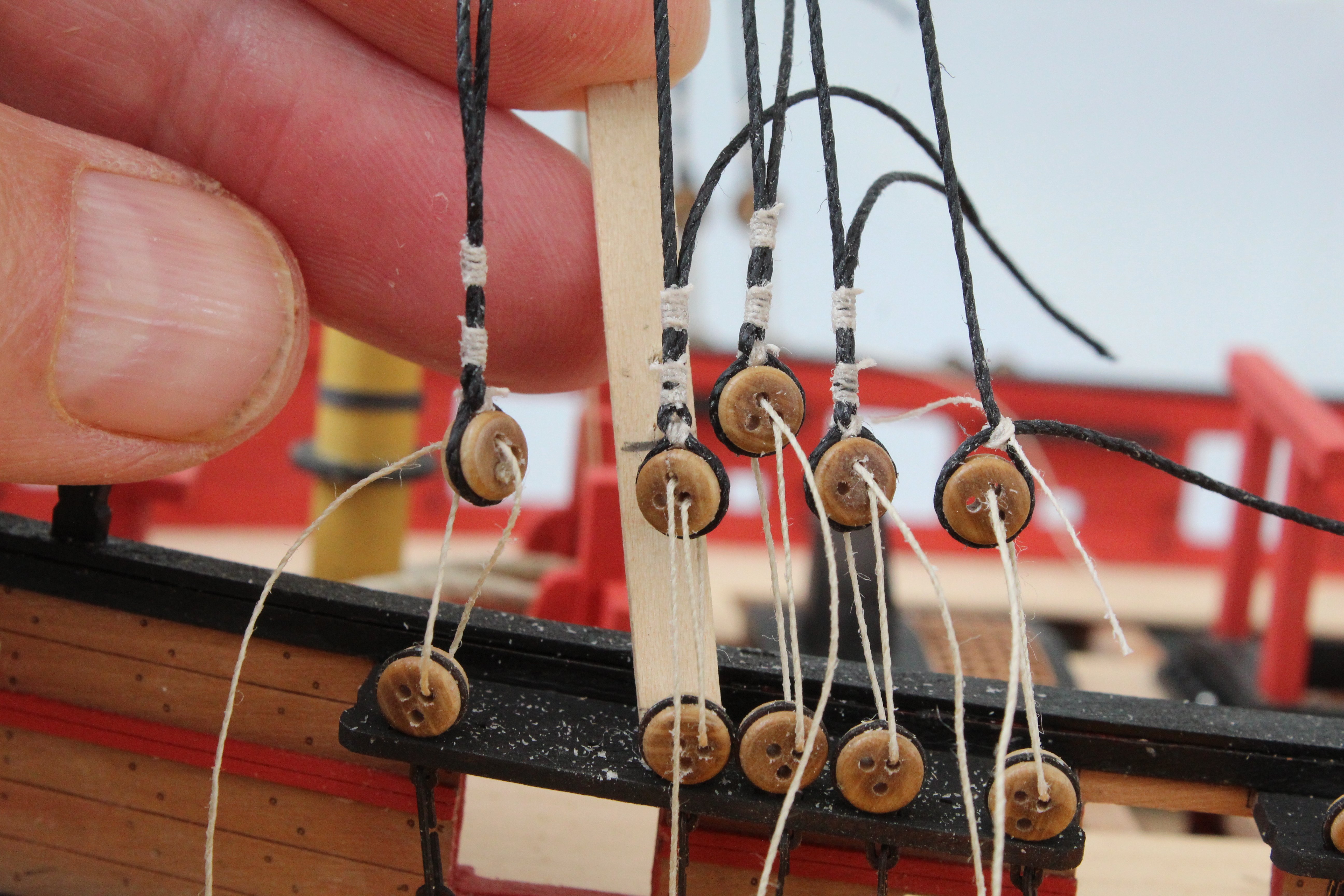
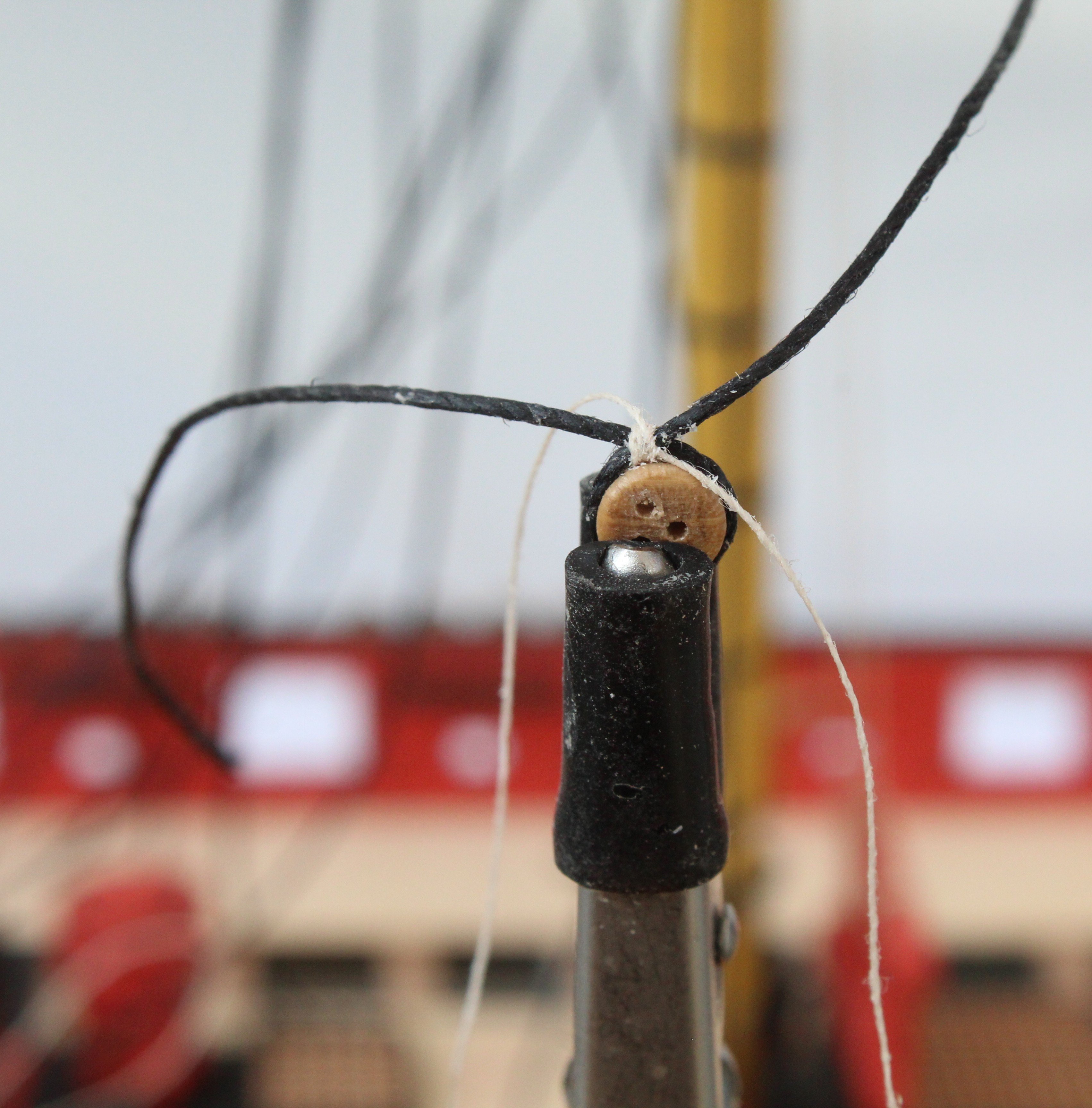
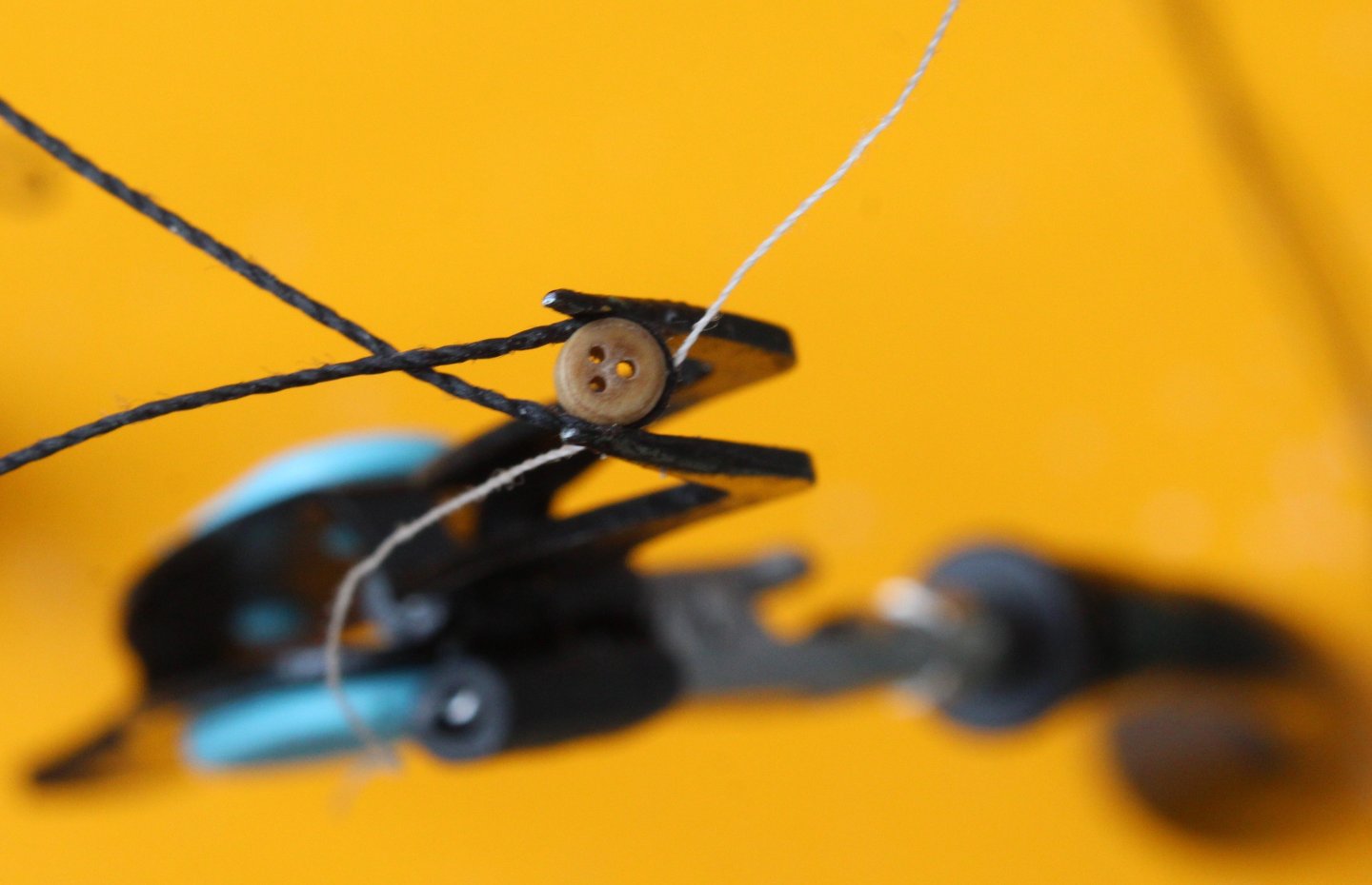
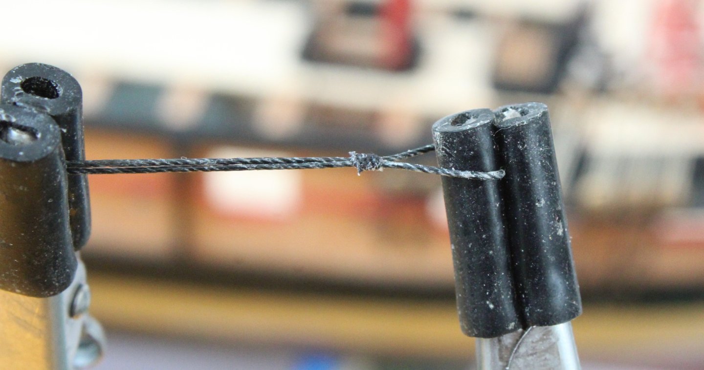
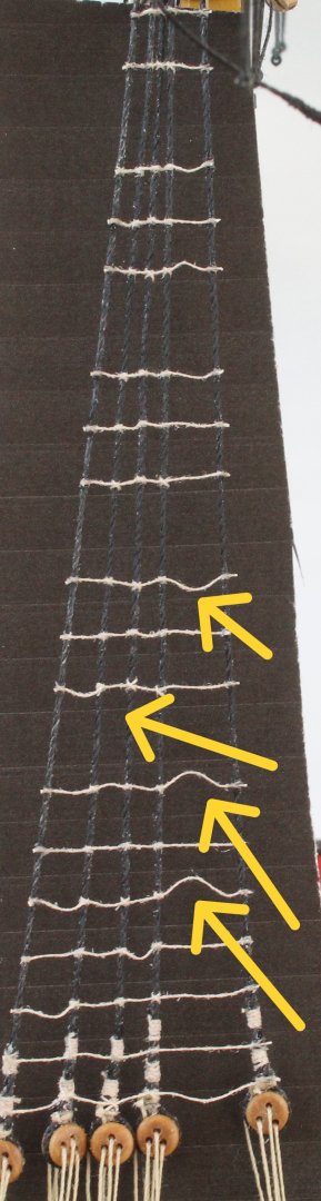
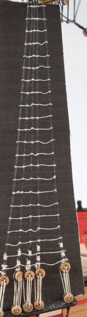
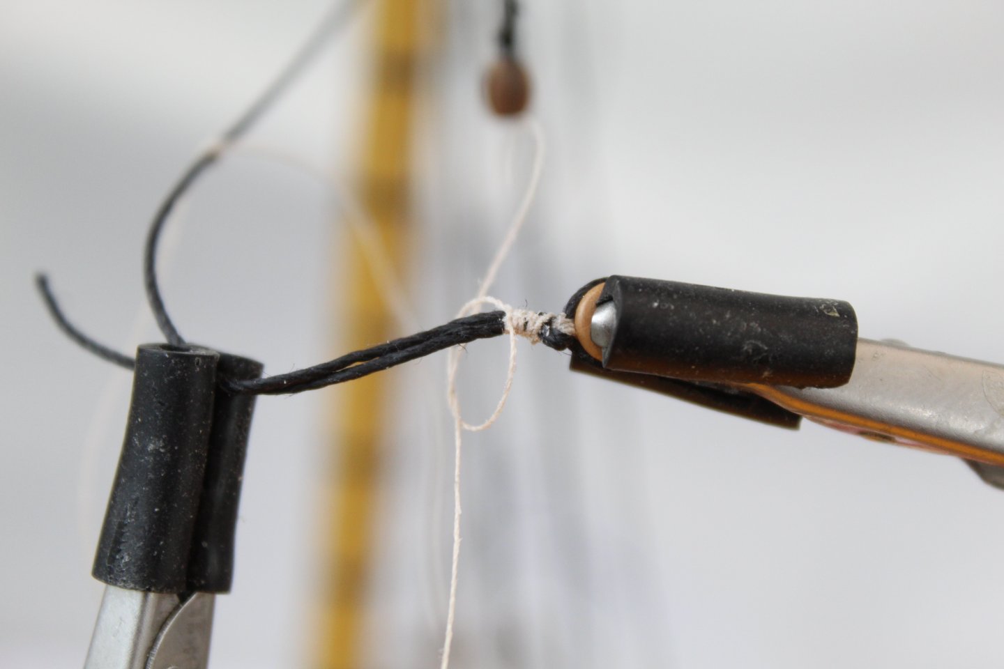
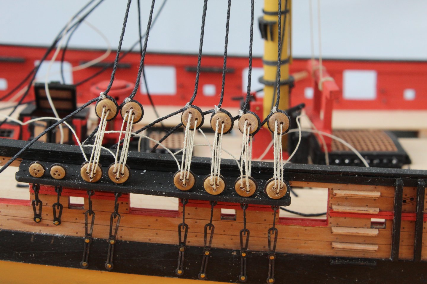
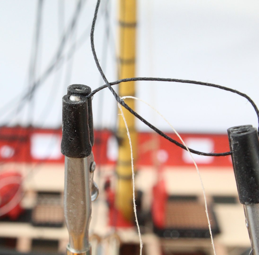
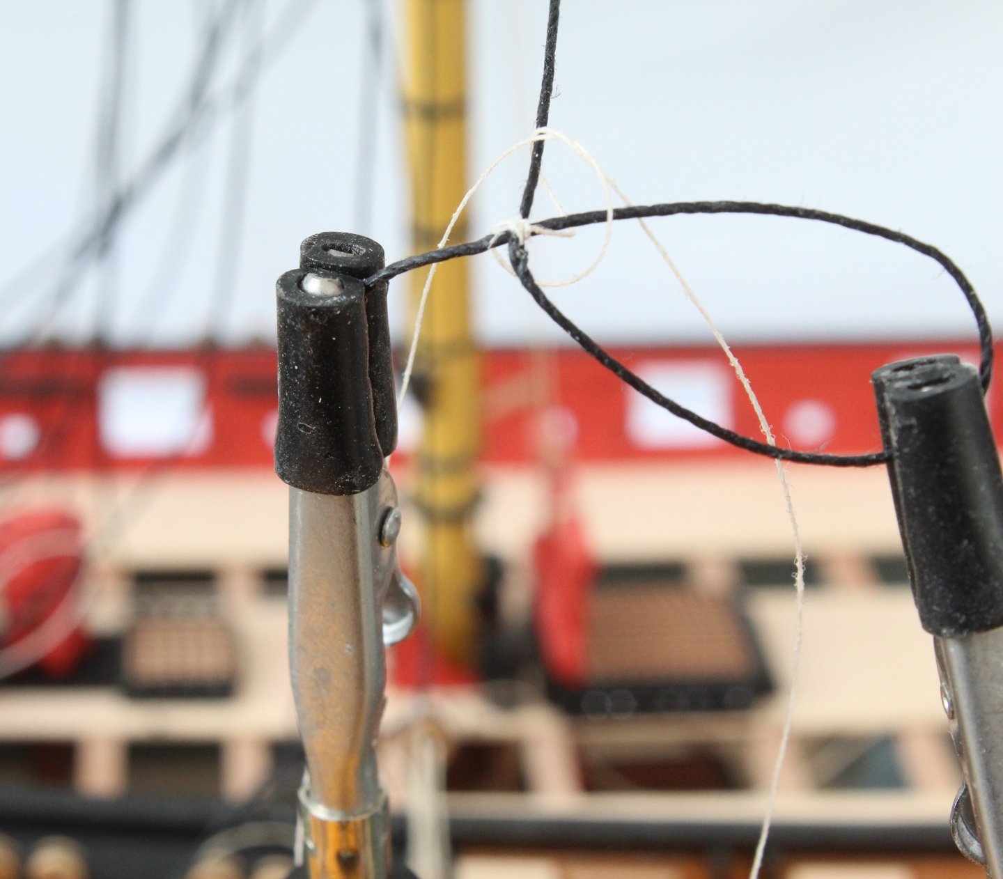
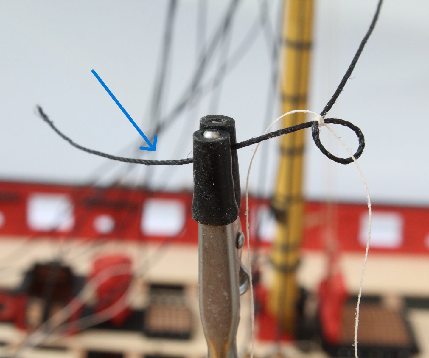
Following on from my last post this is the method I am using to add deadeyes to the shroud lines. It may not work for you, but for me it is a method which produces the most consistent, yet not perfect, results. The best item I bought for model making, especially for the rigging phase is the quad hands. I form a loop in the shroud line and then using the quad hands it can be held in place, as shown below. Next I add three simple cross over knots on the top. In the photo below I am in the process of adding the third crossover knot. The loop can then be closed up by pulling the free end (blue arrow). A deadeye is then placed in the loop, which is pulled tight around the deadeye. After a quick visual check against the other shroud lines a touch of ca glue is added to the seizing and the excess thread cut away. The lanyard is then added as a further check and if necessary the seizing can be removed and redone. The process is repeated until all the deadeyes have been added to the shroud lines. The are not perfectly level but they do tend to follow the slight upward slant of the channel beneath which is to be expected.

- 241 replies
-
- 11
-
-
- Vanguarrd Models
- Harpy
- (and 1 more)
-
Stadler and Waldorf is a great feature in the garden.
- 241 replies
-
- 2
-
-
- Vanguarrd Models
- Harpy
- (and 1 more)
-
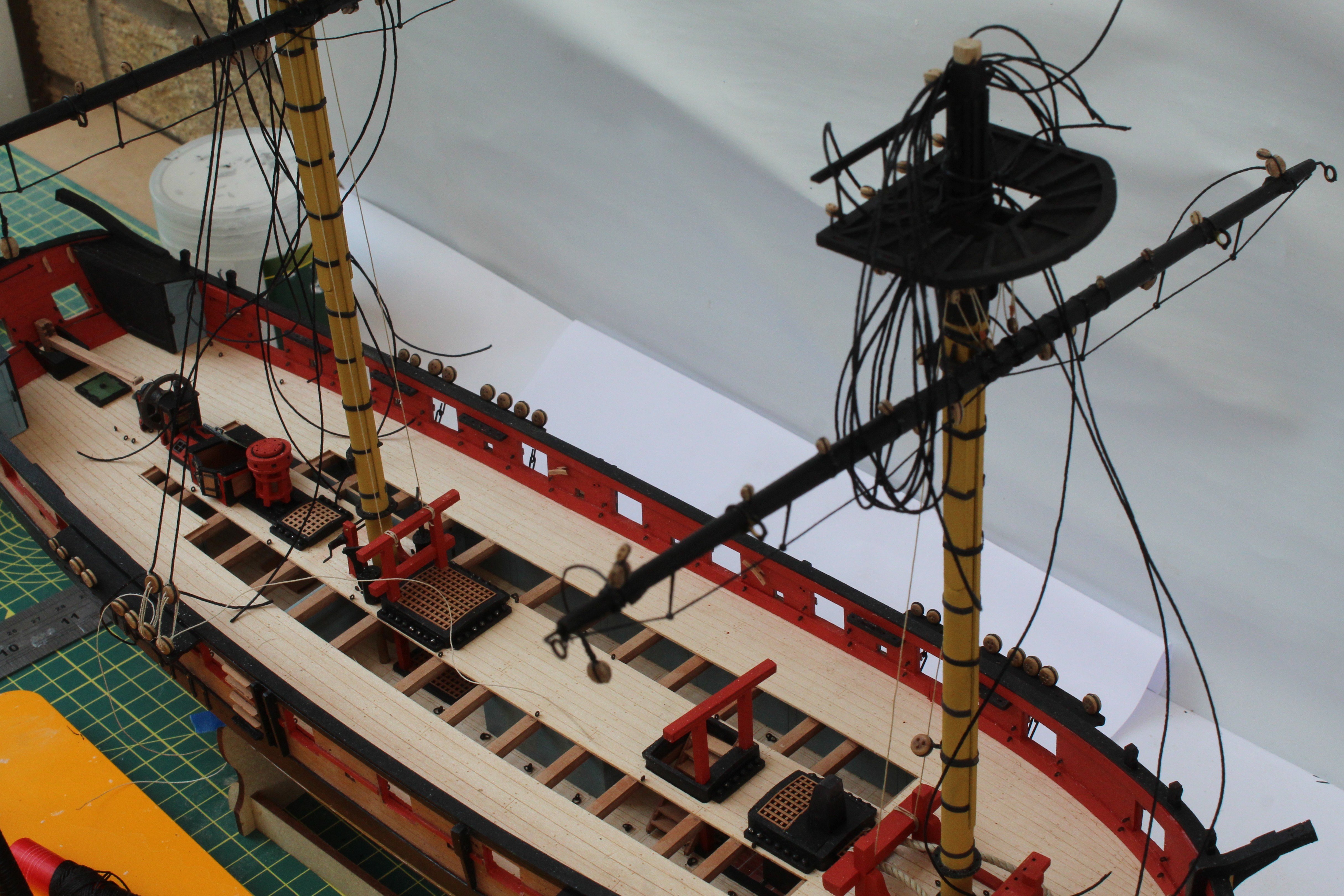
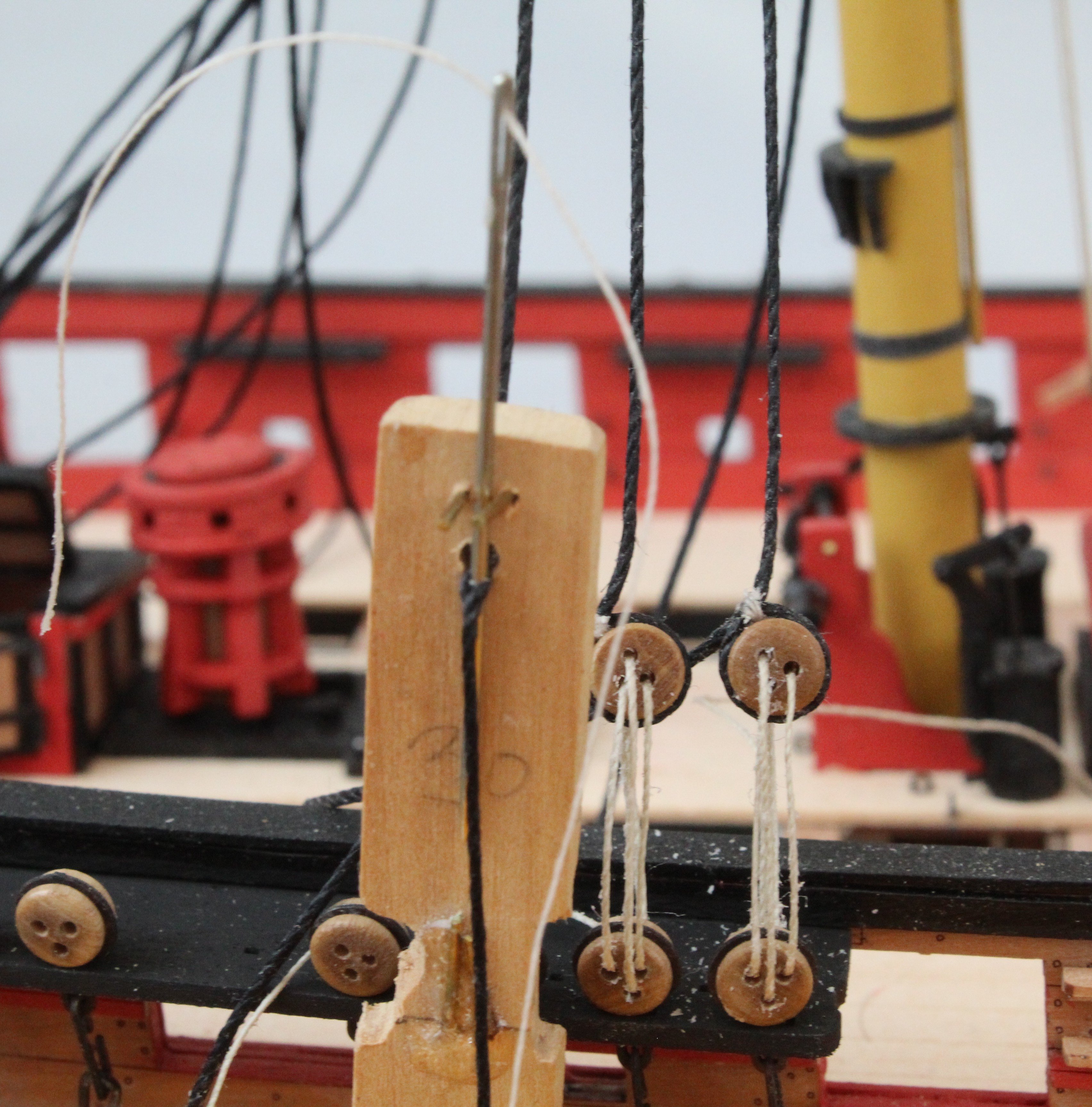
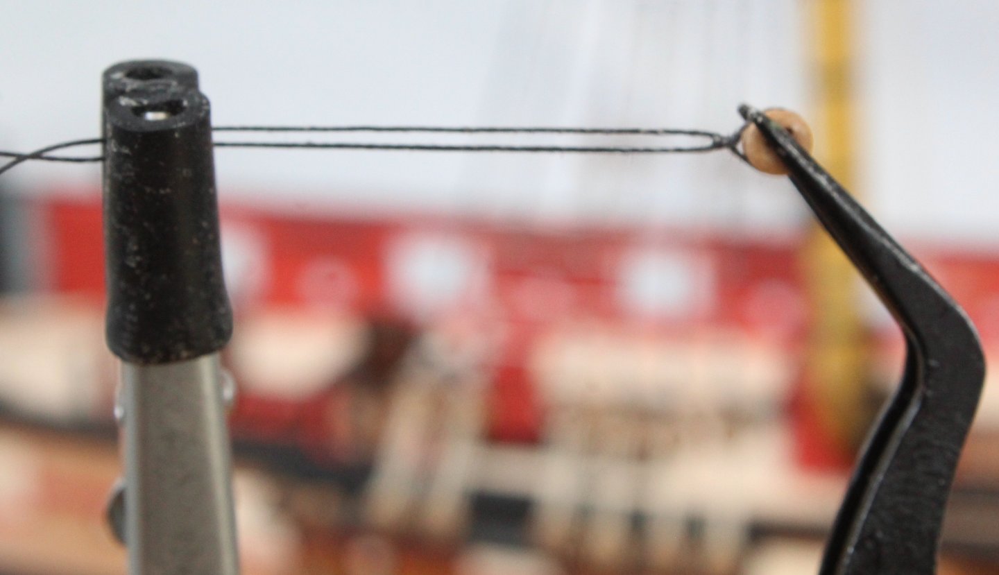
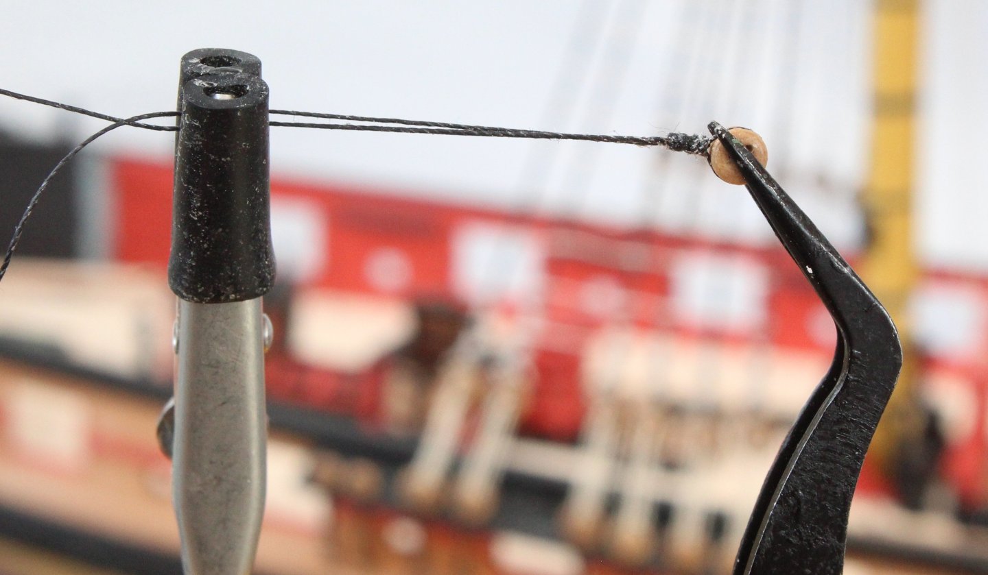
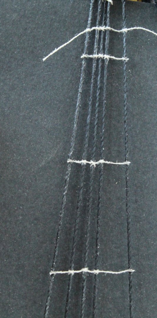
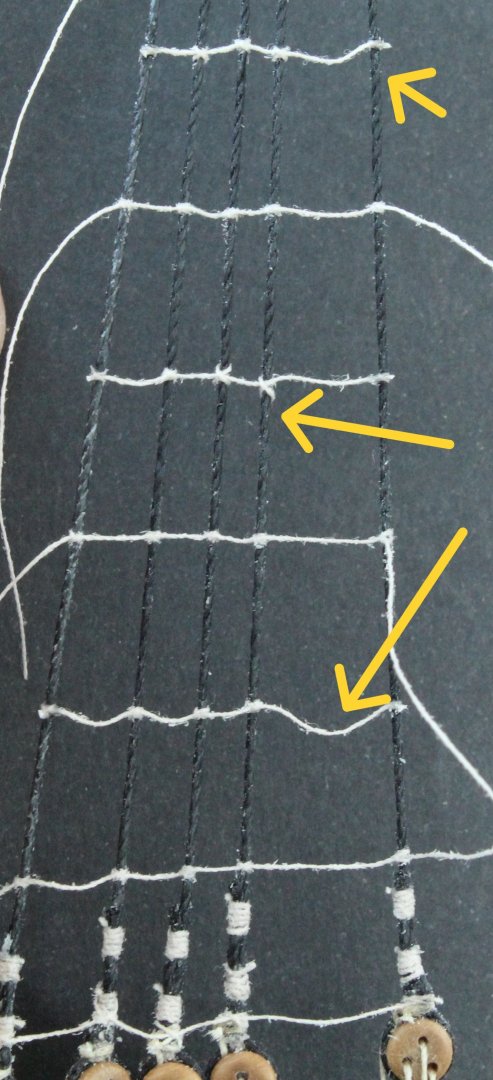
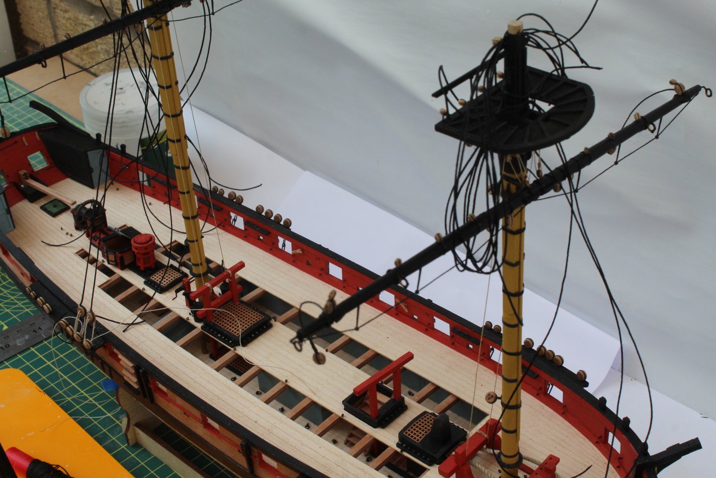
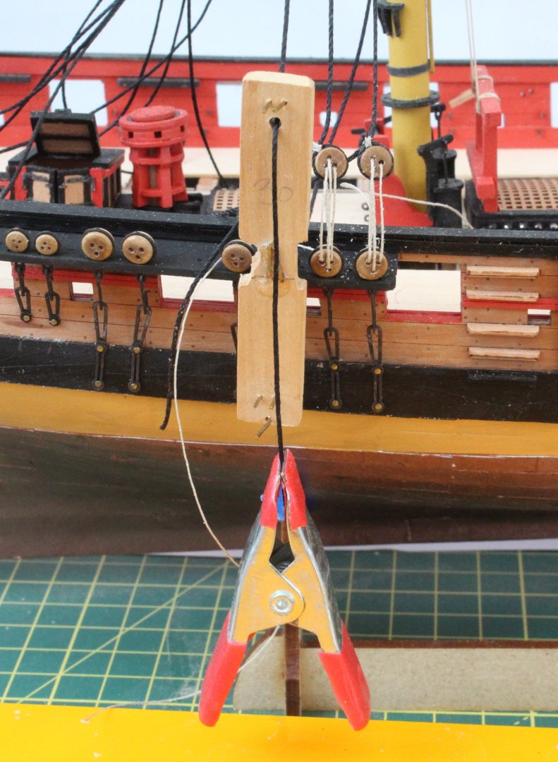
Progress has been a bit slow over the last couple of weeks due to the very nice weather. I decided it was time to revamp the garden pond. I ended up digging a new larger hole (7ftL by 4ftW by 1.5ftD) and fitting a new liner. The fish seem happy in their new home and I added a few more small ones, plus a filter and fountain. Moving on the Harpy progress. I decided to follow @ECK lead and to fit and rig the yards to the masts before starting with the shrouds. It was certainly much easier to do at this stage. Next I started to rig the shrouds. I did an initial check that the method for adding the deadeyes would help to ensure they look reasonably level. It appears to work, noting I will need remove the left-hand lanyard as the deadeye needs to be rotated slightly. The method I am using is to place a jig in the channel deadeye. The shroud is passed through a hole and held in place using a clamp. The seizing thread is then passed through the shroud line, as shown in the next photo, using a needle. The jig is then removed from the channel and the shroud and seizing is then pulled back through the hole. The final check is to make sure the seizing thread for the adjacent shrouds looks level. In my next post I will detail how the deadeye is added to the shroud.


- 241 replies
-
- 11
-
-
- Vanguarrd Models
- Harpy
- (and 1 more)
-
The deadeyes and blocks look great and much better quality than the kit supplied items. In particular I am having to sort through the 3mm deadeyes for usable ones as the position of the three holes is very erratic.
- 332 replies
-
- 4
-
-
- Harpy
- Vanguard Models
- (and 1 more)
-
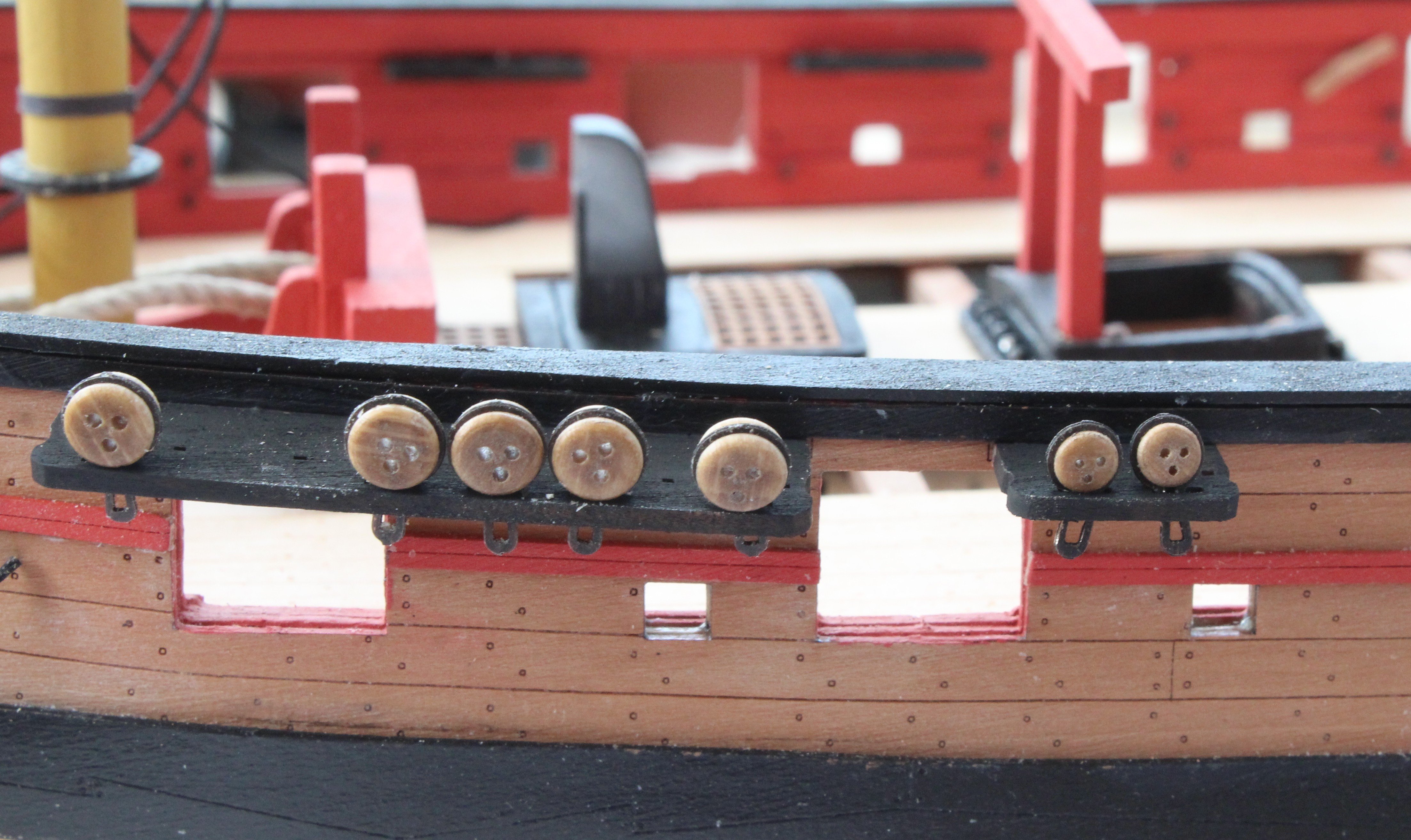
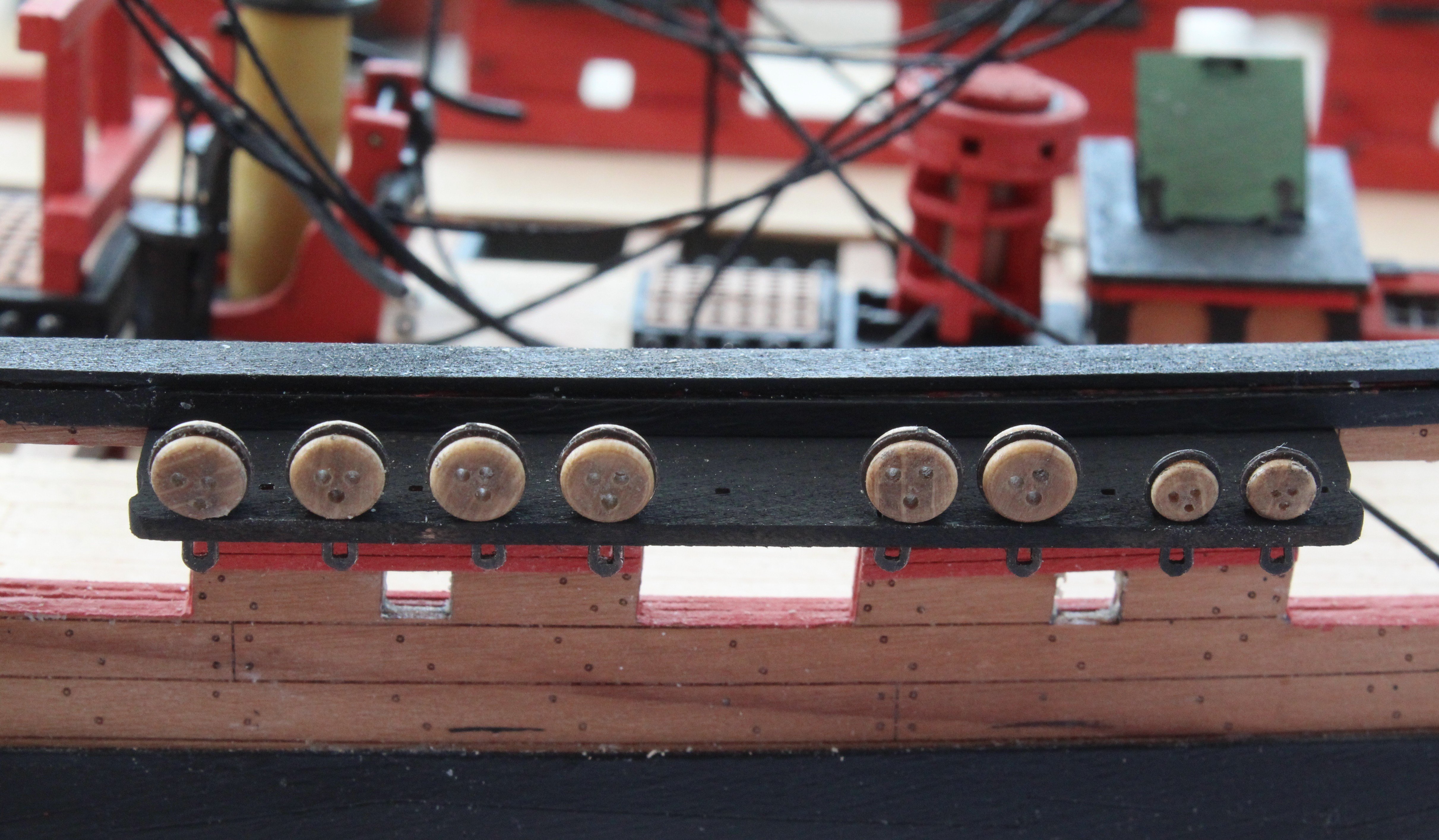
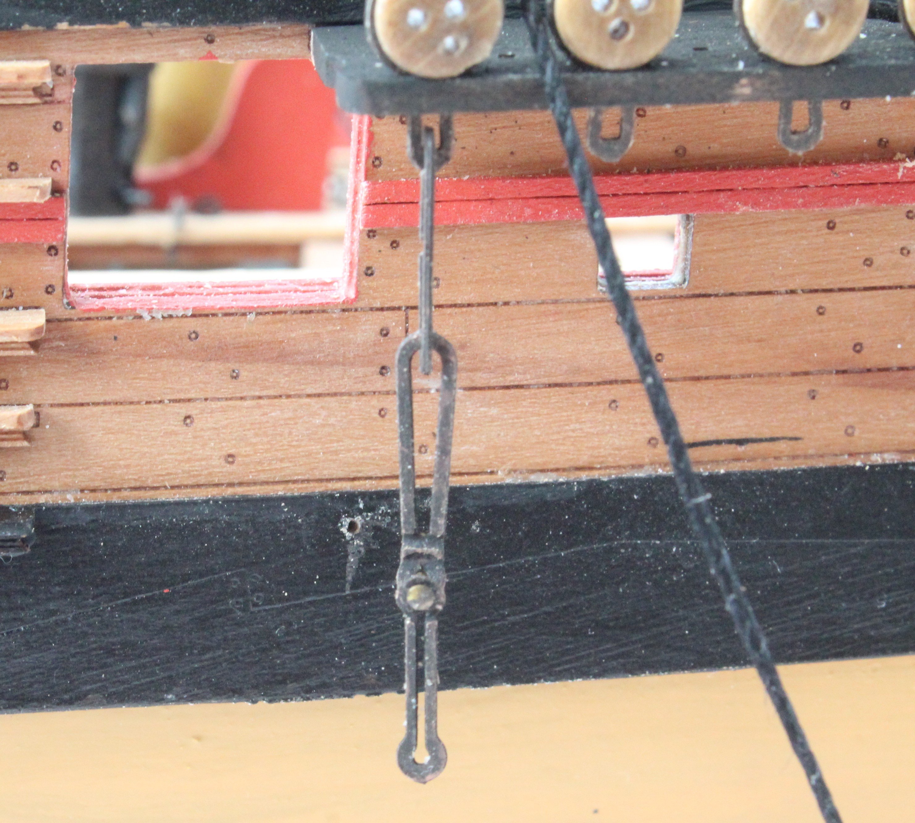
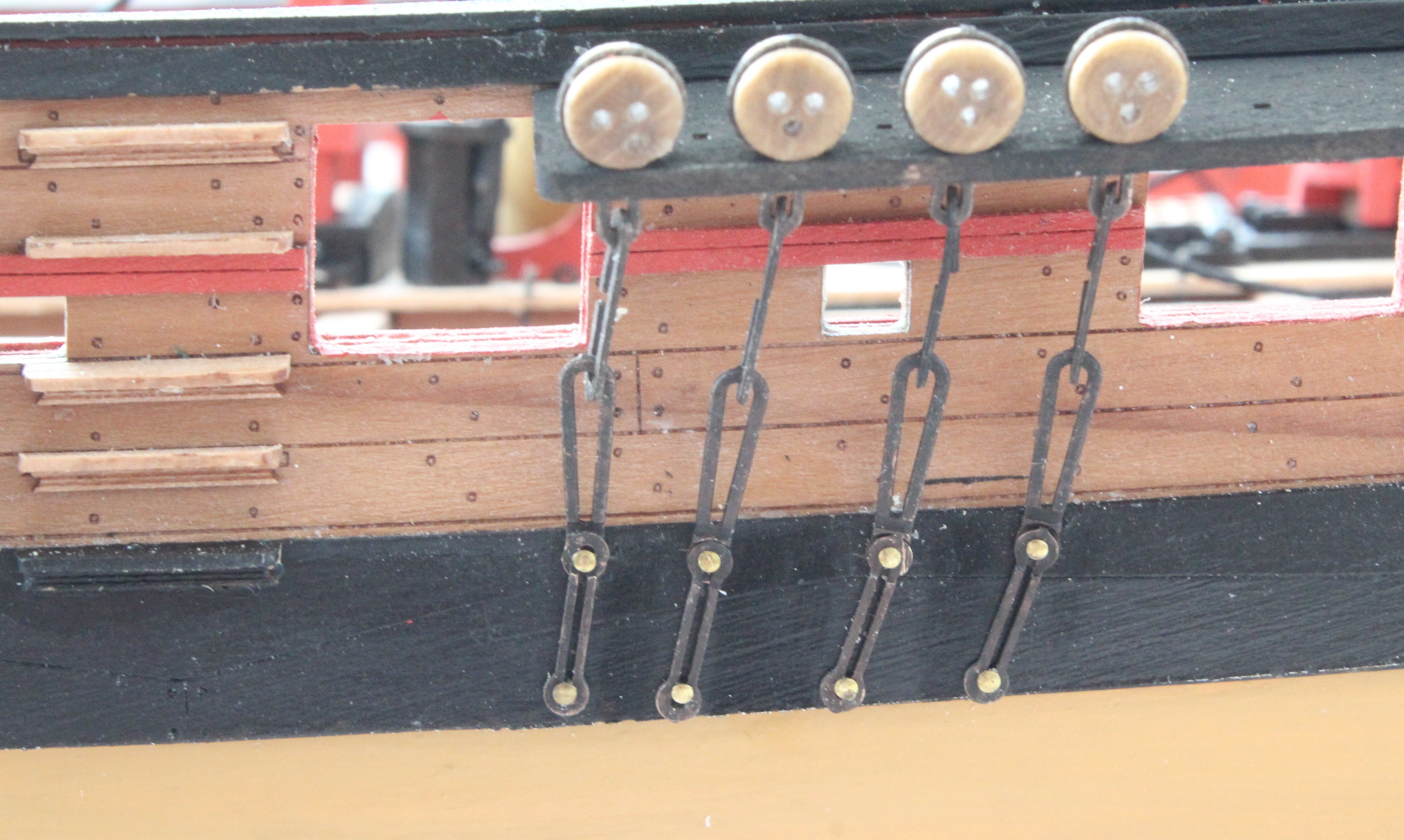
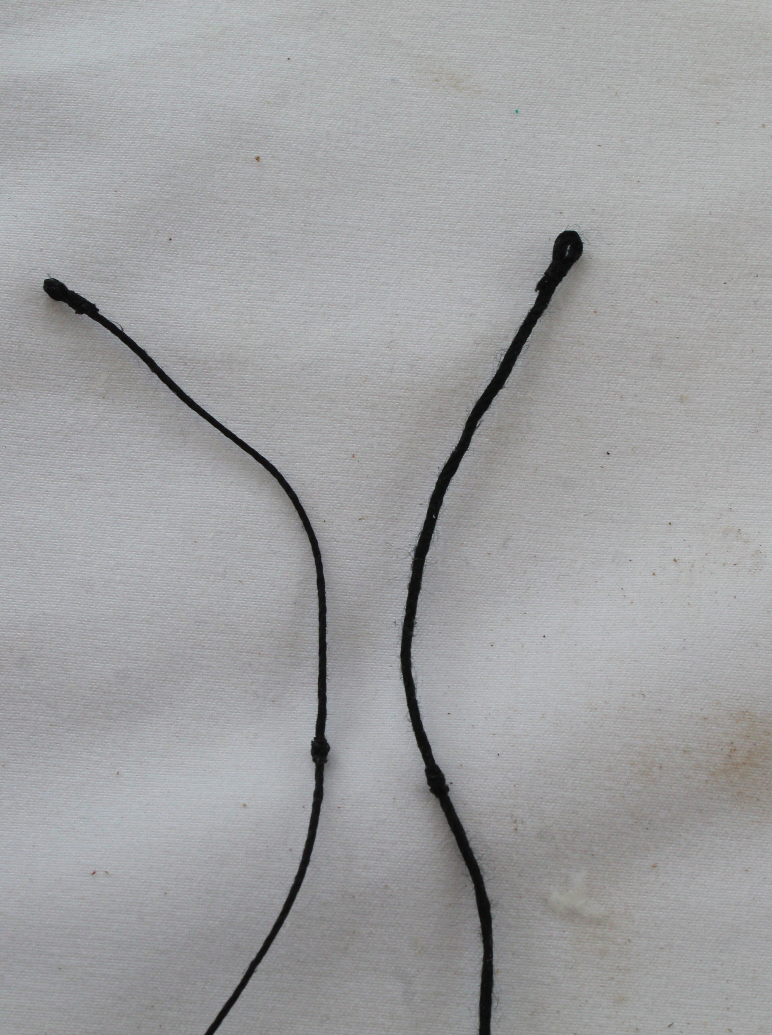
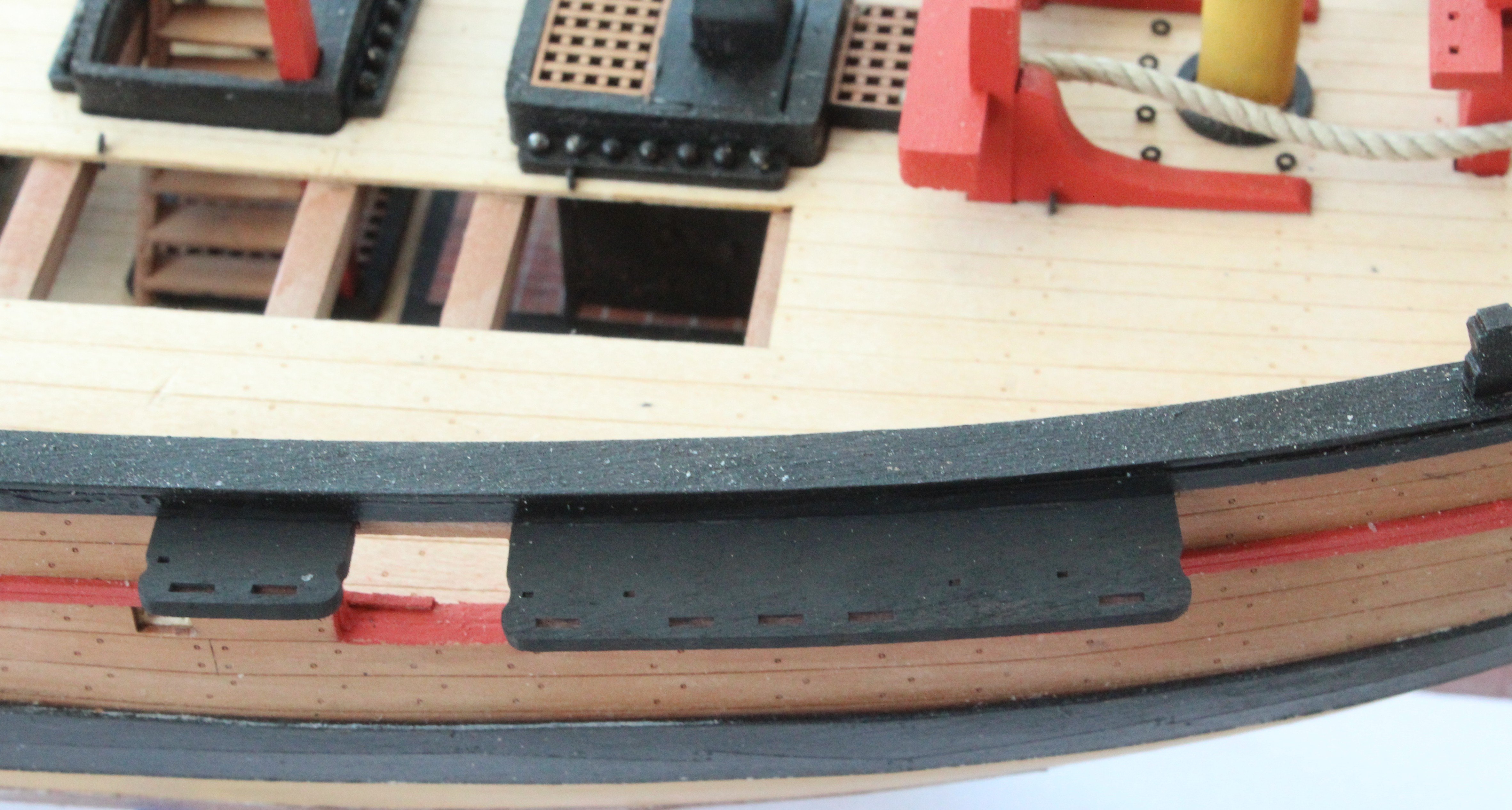
A mixed bag of items in this post detailing what I have been working on over the last few days. I have made all the main and fore mast shroud lines. They have been position on the two masts but they can be removed if required before I a, ready to add the lanyards. I have also made the main and foremast stays and preventor stays, and one pair is shown below. Next I moved on to adding the various blocks and footropes to the main yard. The first task was to seize threads to all the blocks. The yard was then held in position, using my quad hands. In the next photo the central blocks have been added to the yard. The footropes have also been added. Moving outwards the next three blocks were added to the yard. In the next photo all the blocks and footropes have been added. The yard was then then test fitted to the mast. The next job was to add the deadeyes to their respective strops. Next I started to add the chain plates and links. Using the shroud line as a guide I marked the position for the first chain plates and link. The first four chain plates and links have now been added.


- 241 replies
-
- 15
-
-
- Vanguarrd Models
- Harpy
- (and 1 more)
-
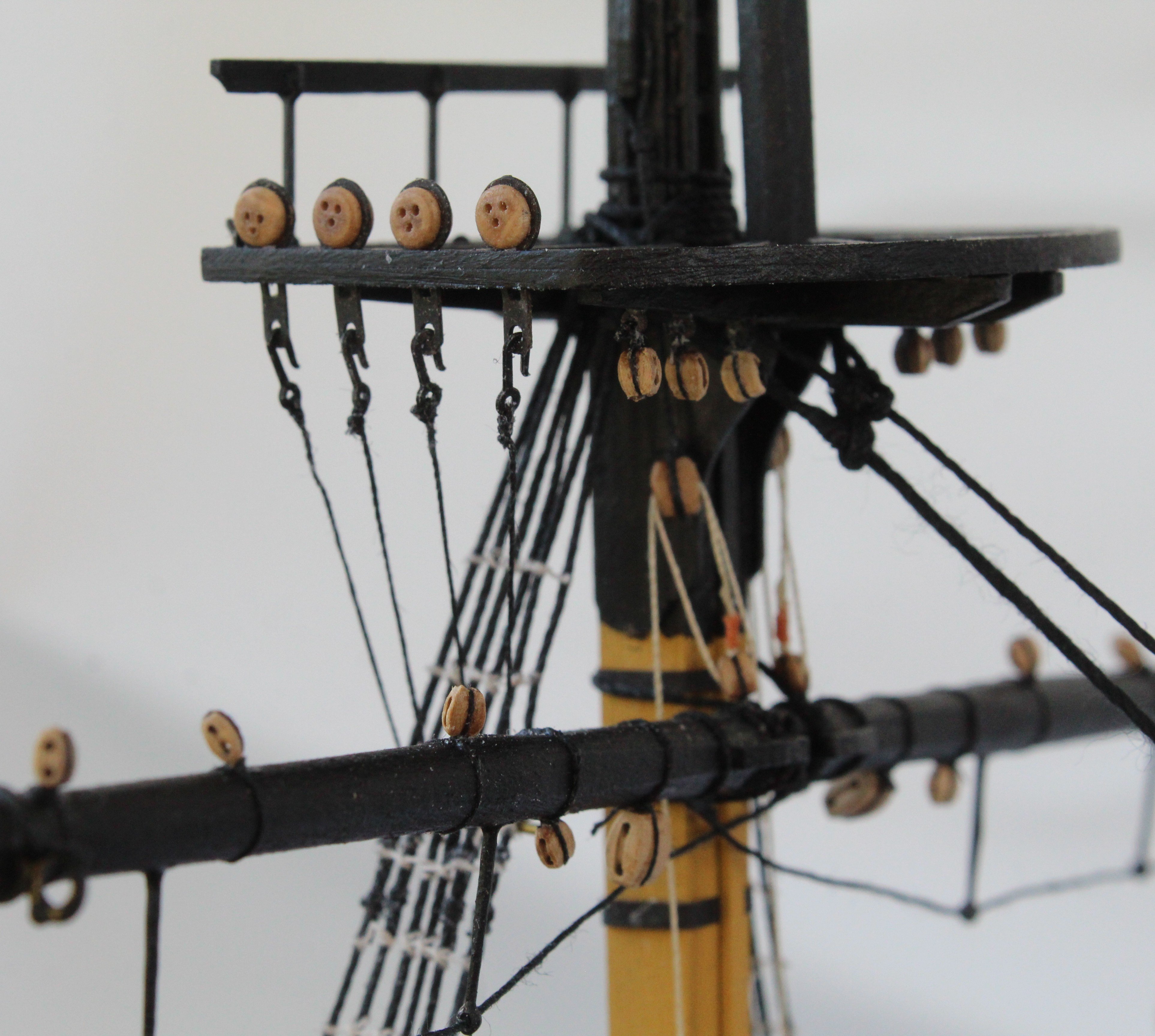
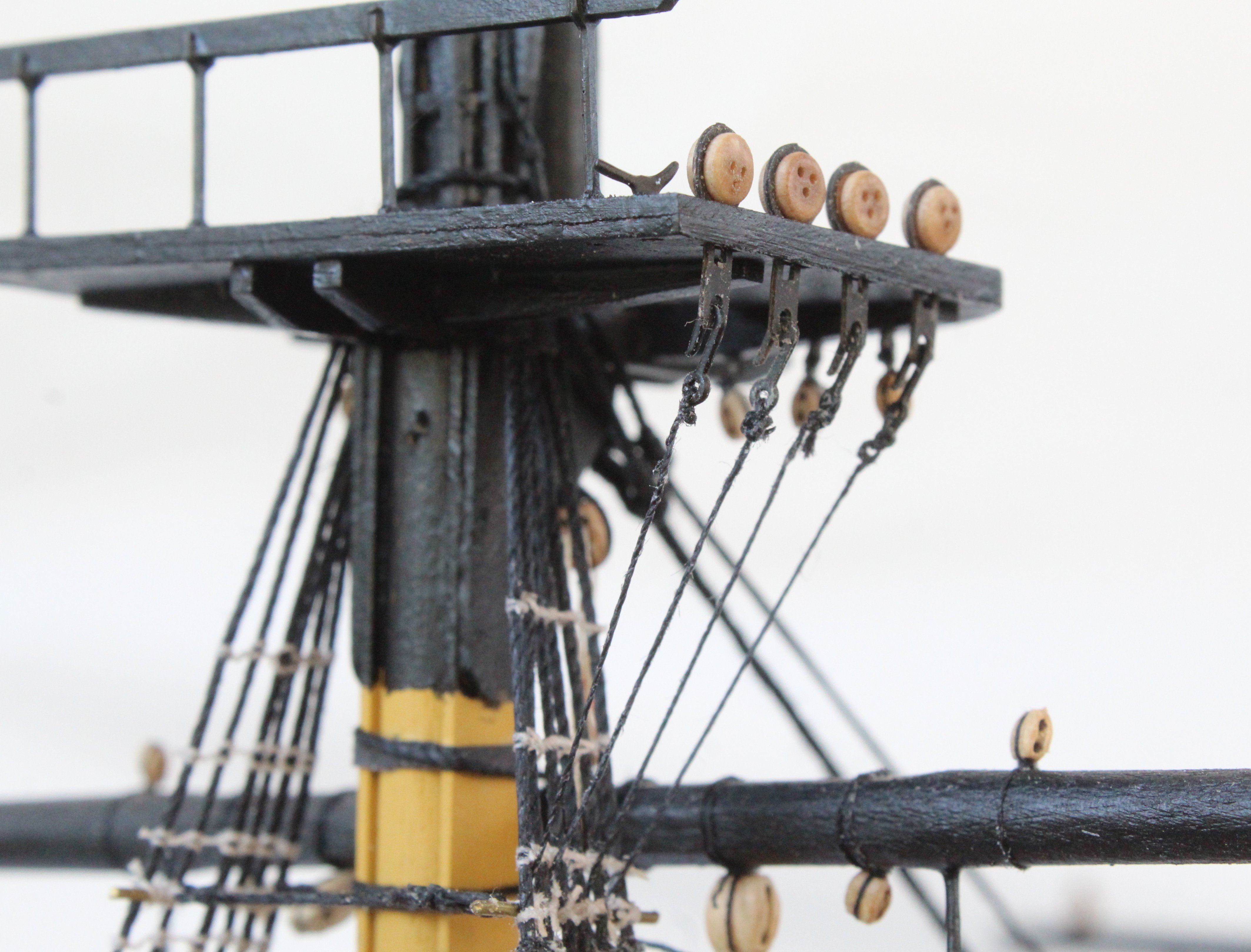
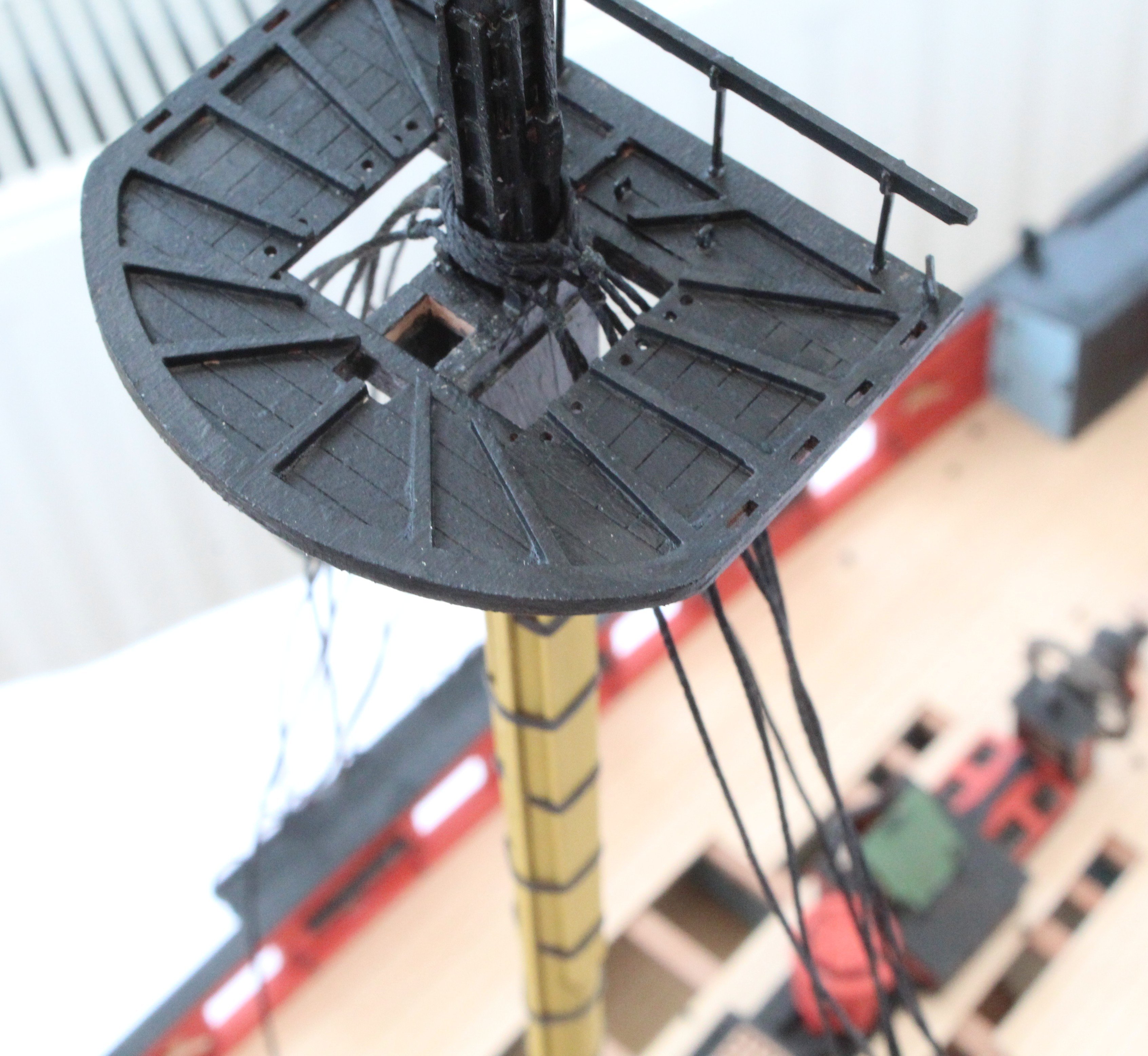
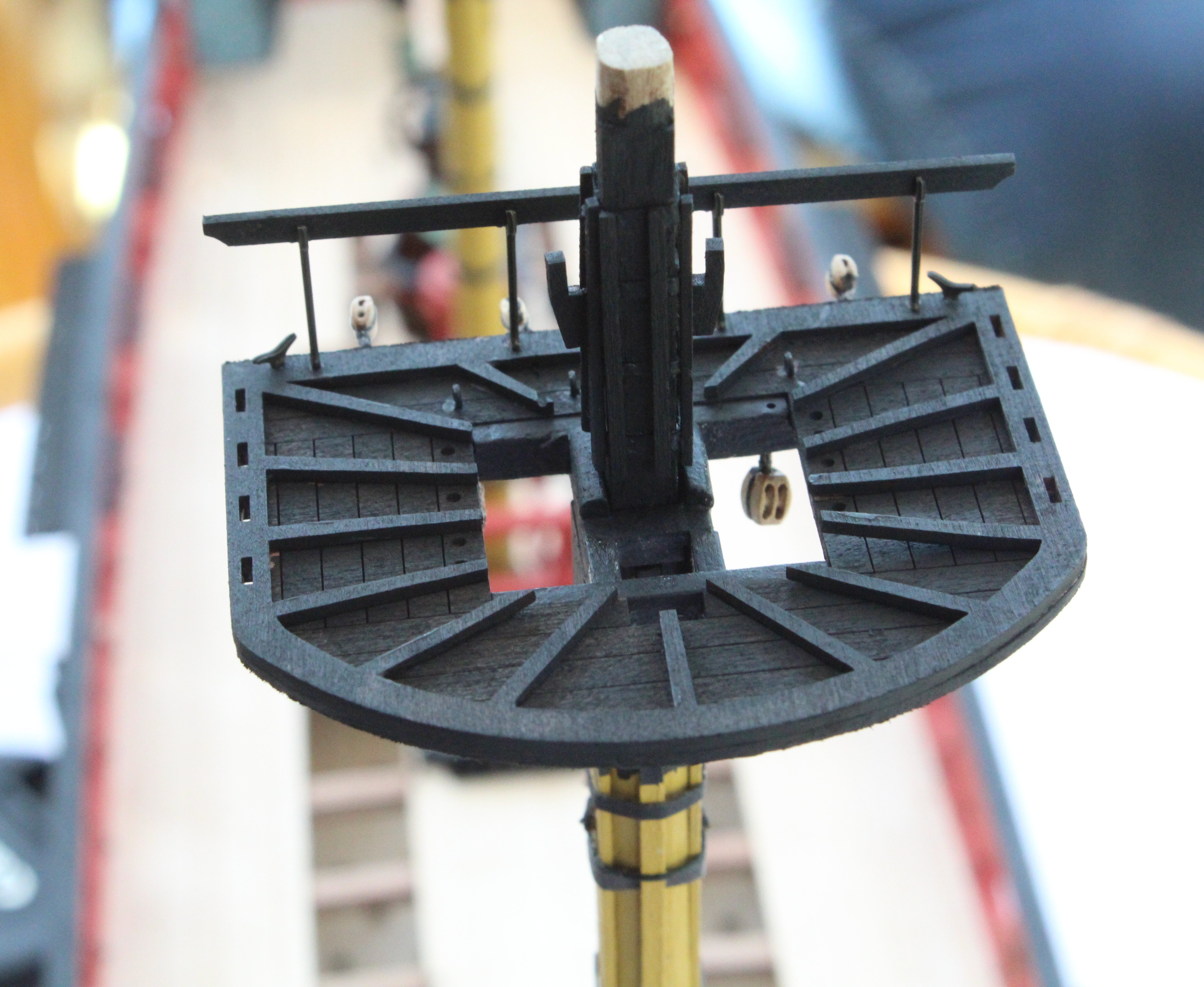
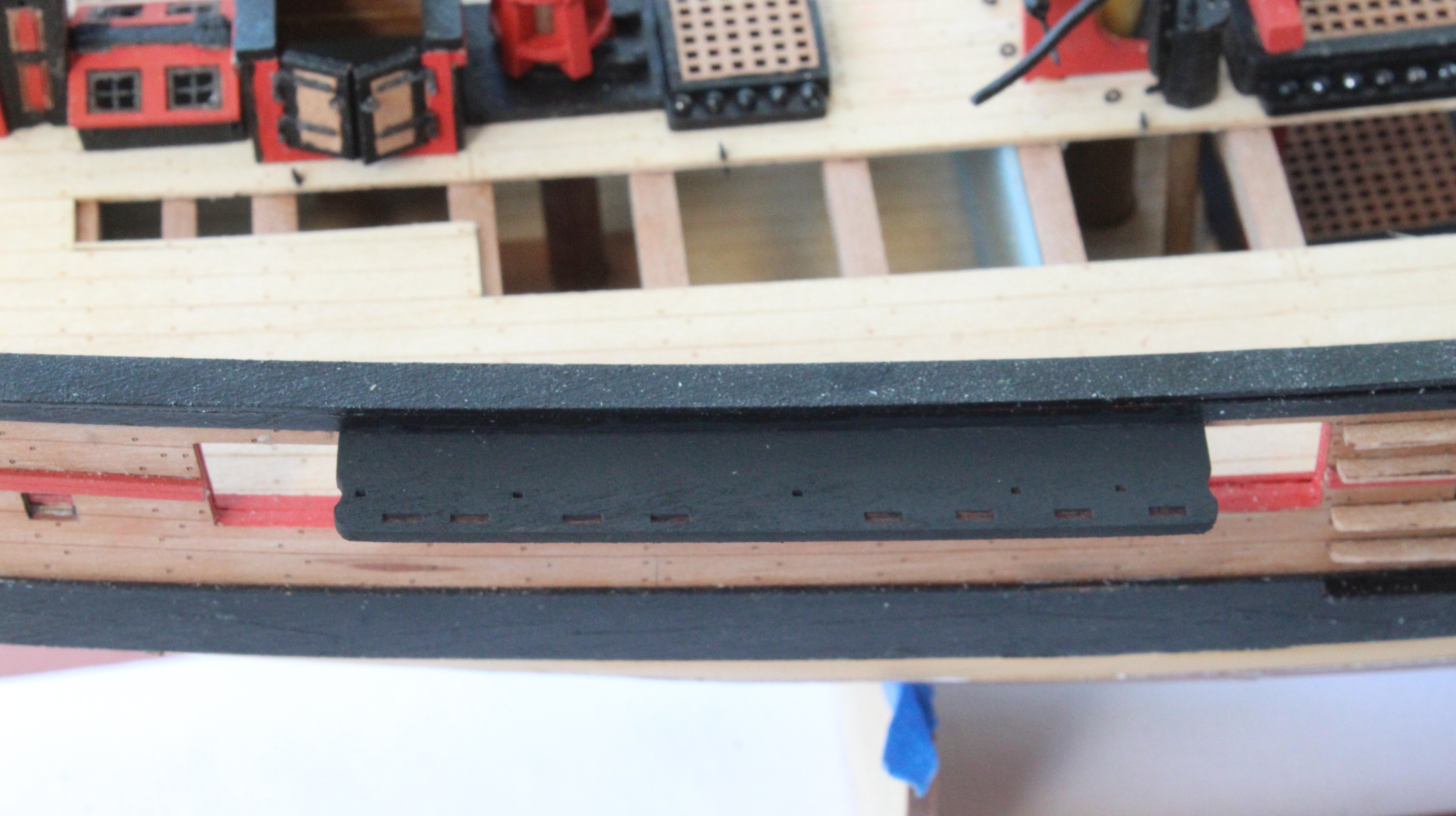
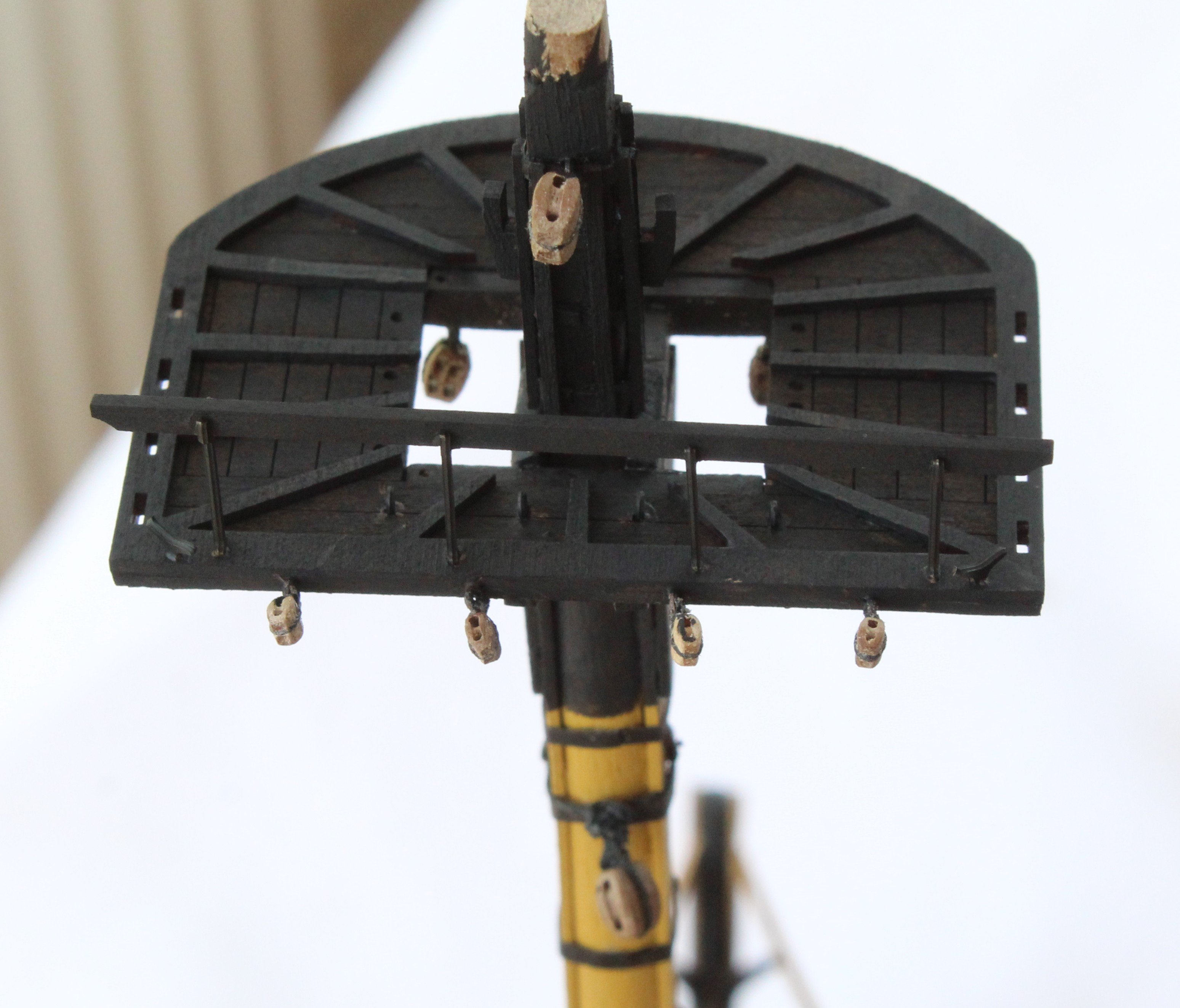
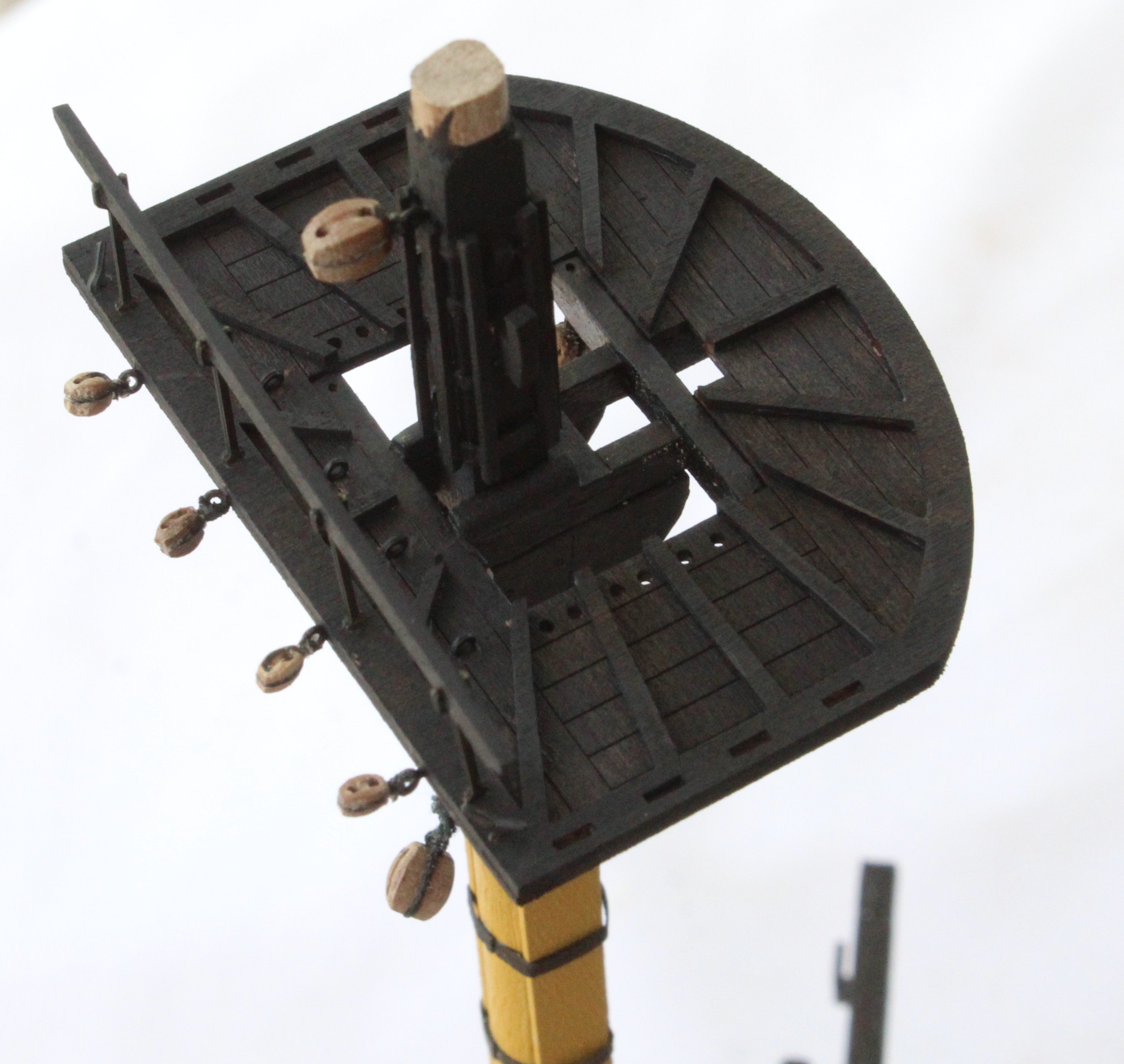
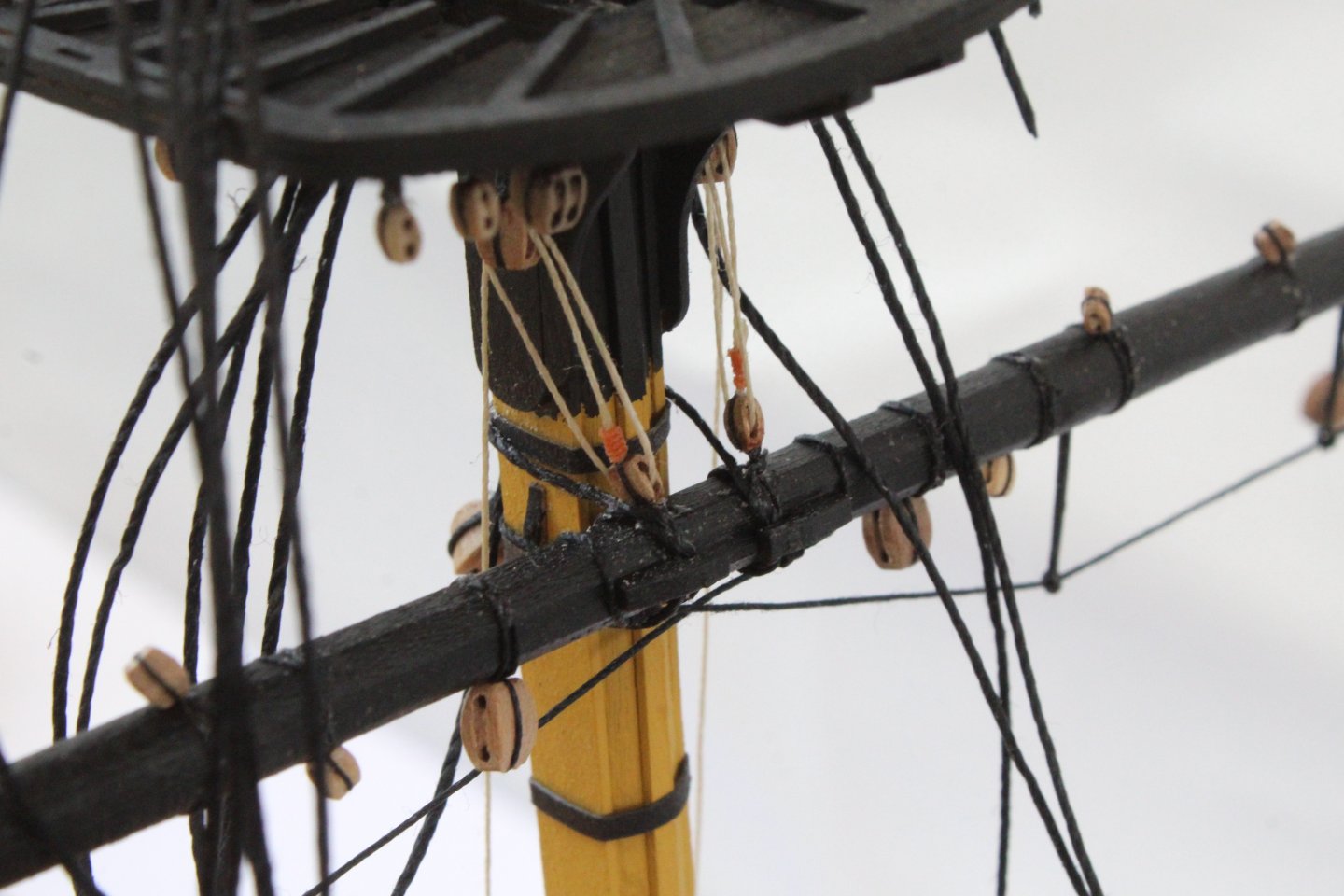
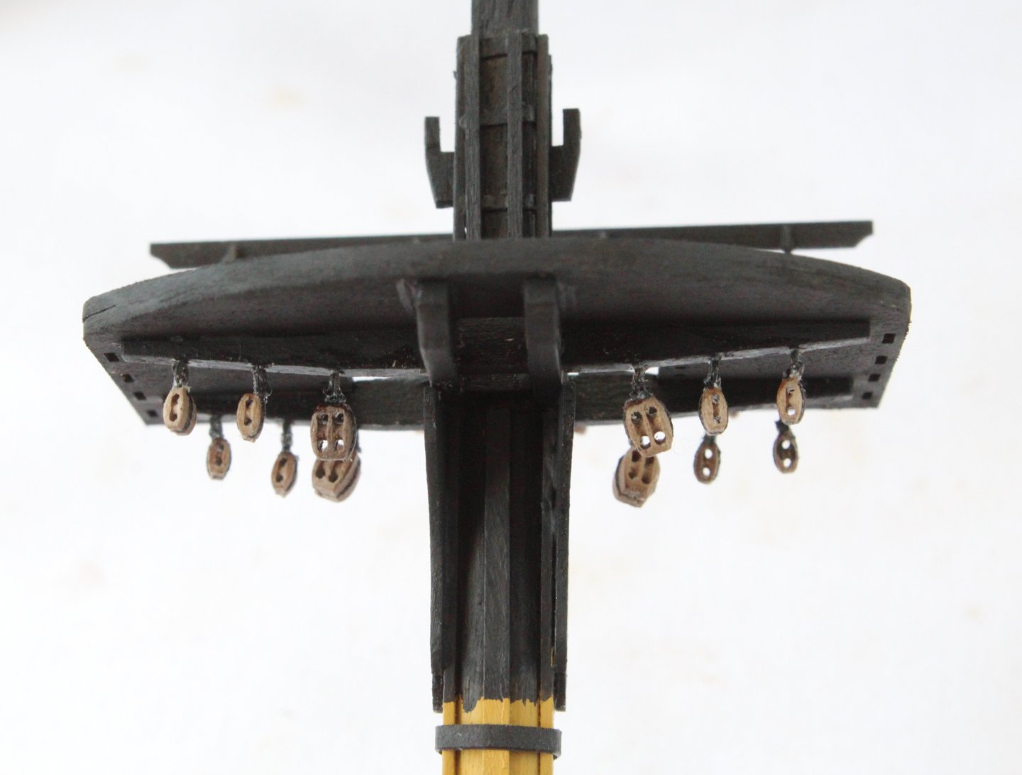
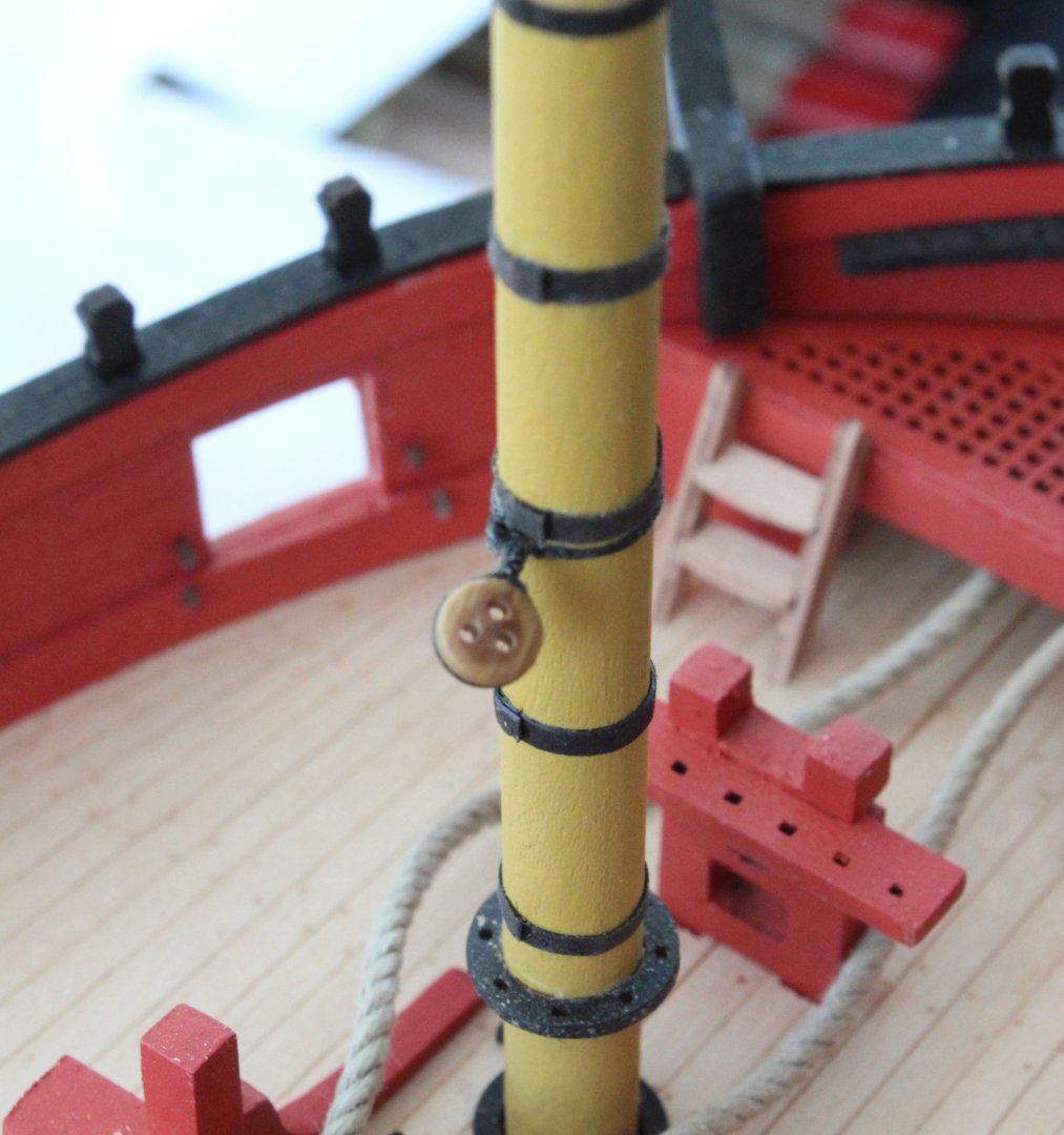
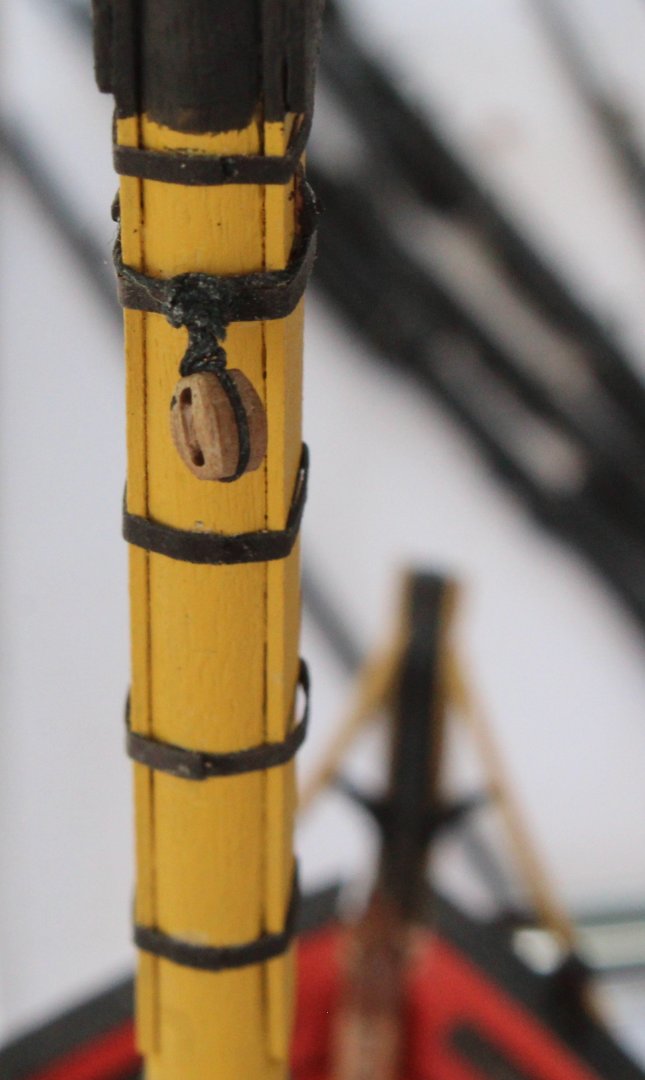
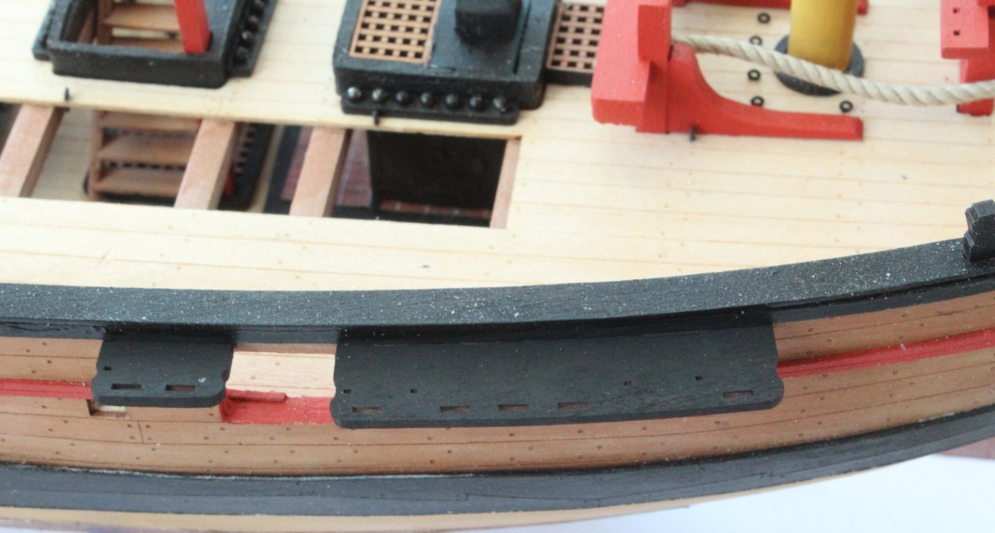
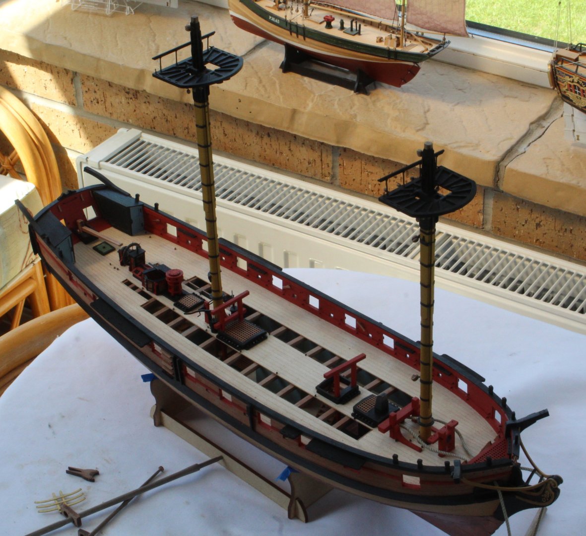
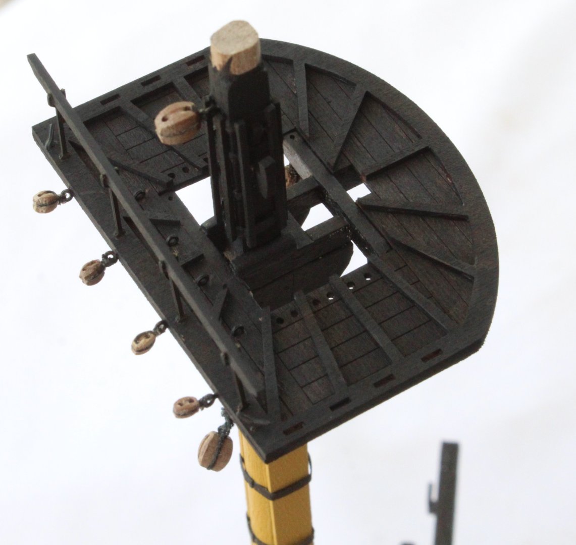
Work has been progressing slowly on the Harpy, partly due to a short holiday and partly due to enjoying the mini heatwave. I have completed all the work related to the main and foremast, such as: a) The platforms have been added b) The various PE parts have been added c) The various blocks have been added d) Cleats and iron banding have been added above the platform I have also added the channels to the hull. I am waiting a new supply of blackening solution so the strops and chain plates can be blackened before they are added.


- 241 replies
-
- 14
-
-
- Vanguarrd Models
- Harpy
- (and 1 more)