HOLIDAY DONATION DRIVE - SUPPORT MSW - DO YOUR PART TO KEEP THIS GREAT FORUM GOING! (89 donations so far out of 49,000 members - C'mon guys!)
×


Glenn-UK
-
Posts
3,162 -
Joined
-
Last visited
Content Type
Profiles
Forums
Gallery
Events
Everything posted by Glenn-UK
-
 Thanks John
 -
It is a beautiful model. My daughter-in-law has always admired the one I built a while ago so I am now going to build one for her.
-
That would be my intention however this build is now on the back burner as I have a new commission build which I am eager to start. I am happy that the Grecian sad it stands will be ready for mast/yard/rigging if or when I have time to return to the build.
-
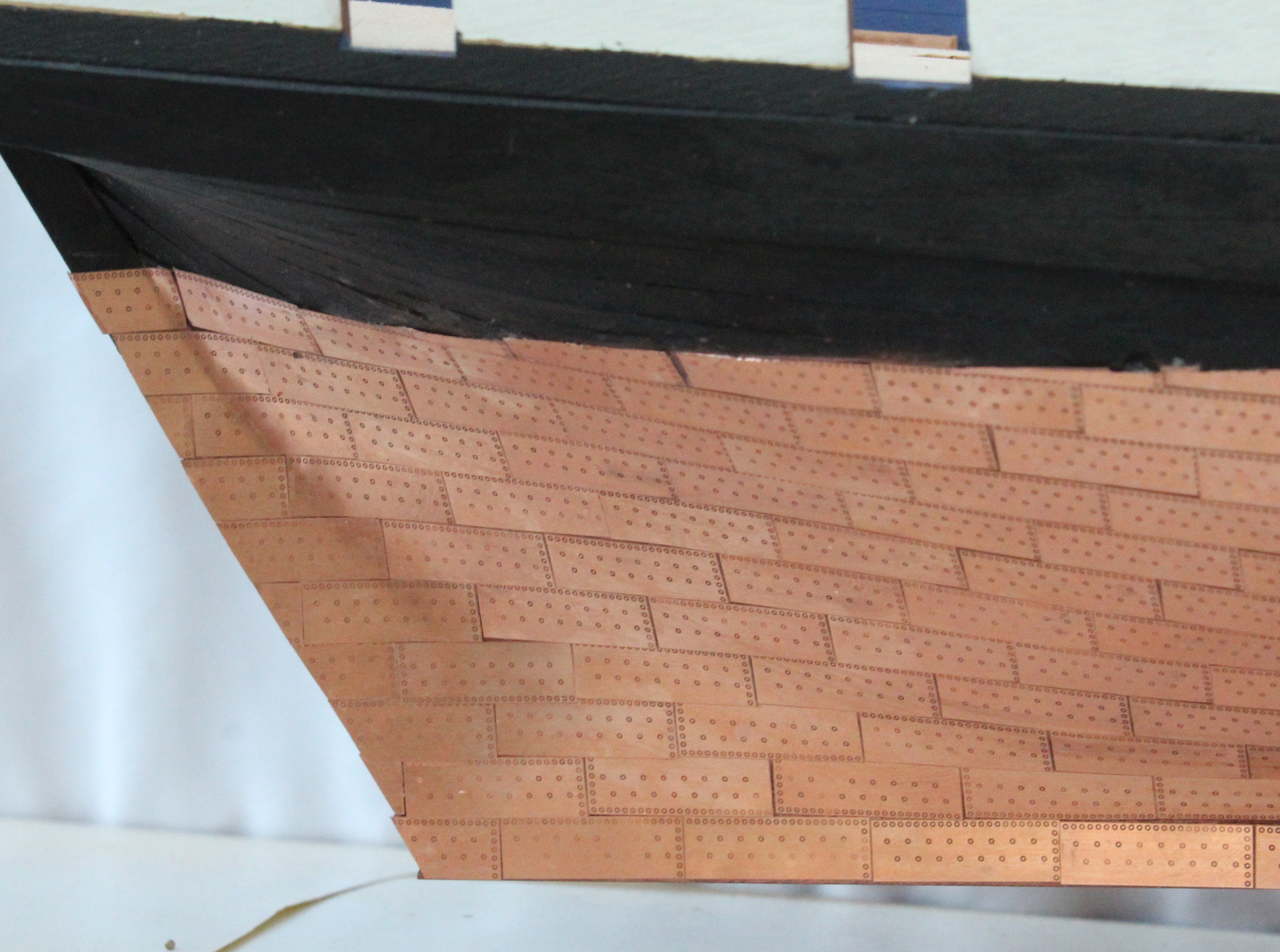
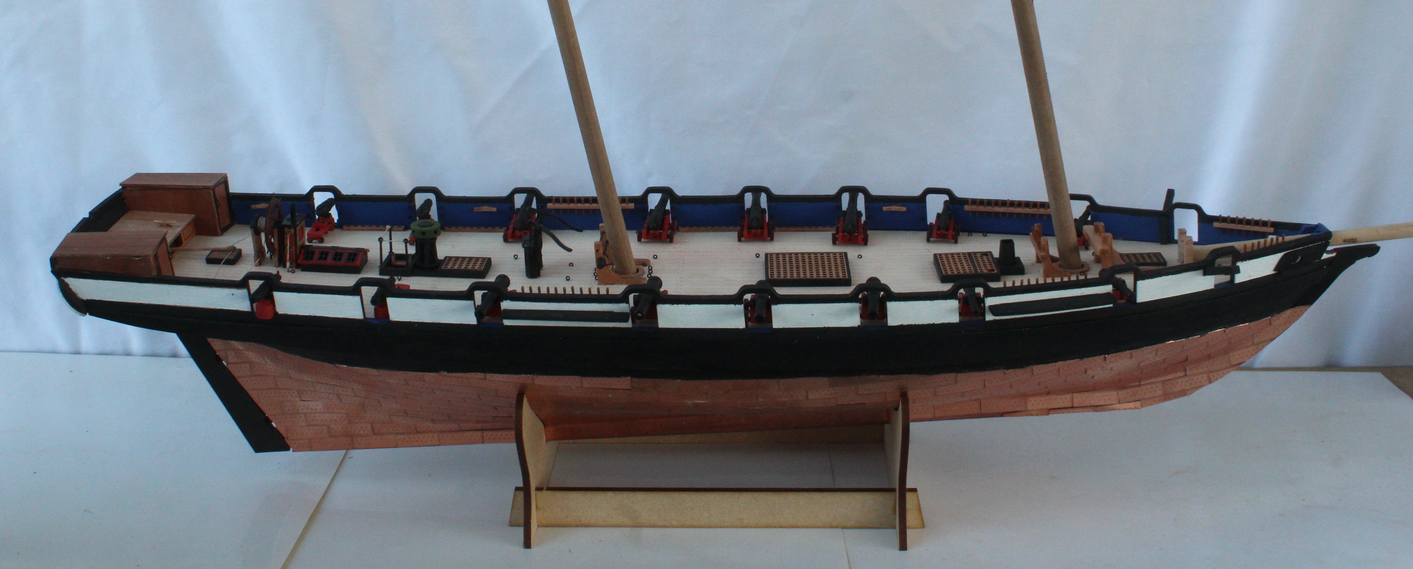
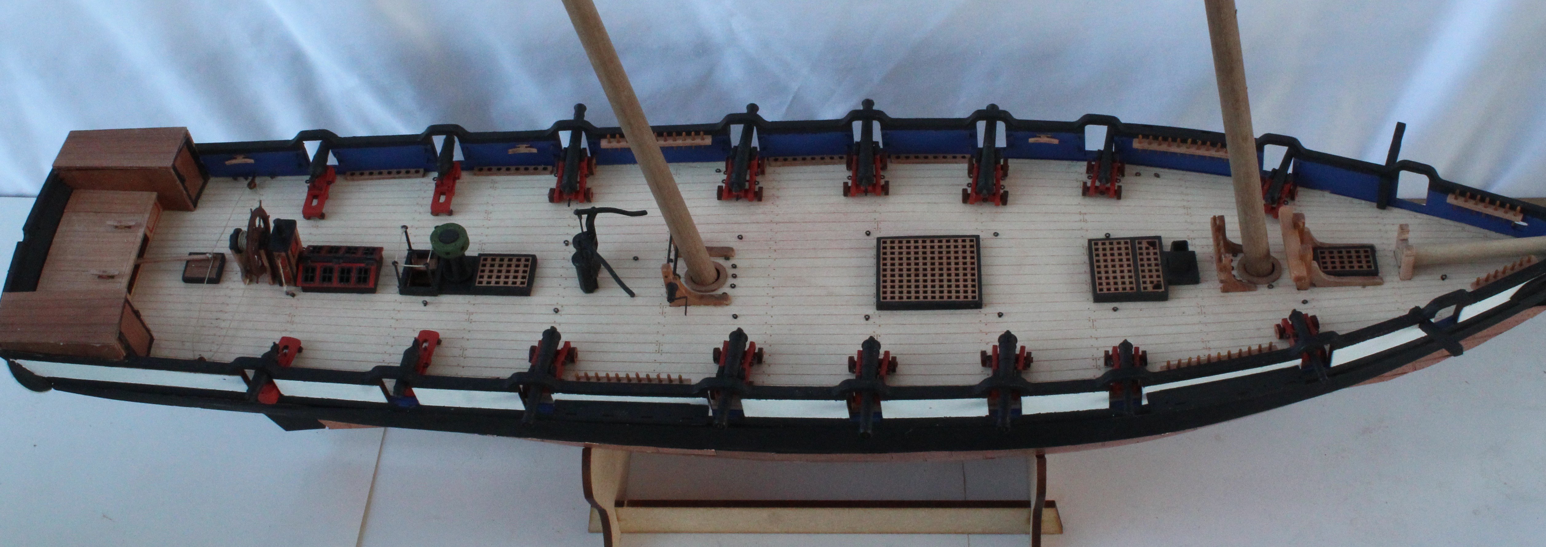
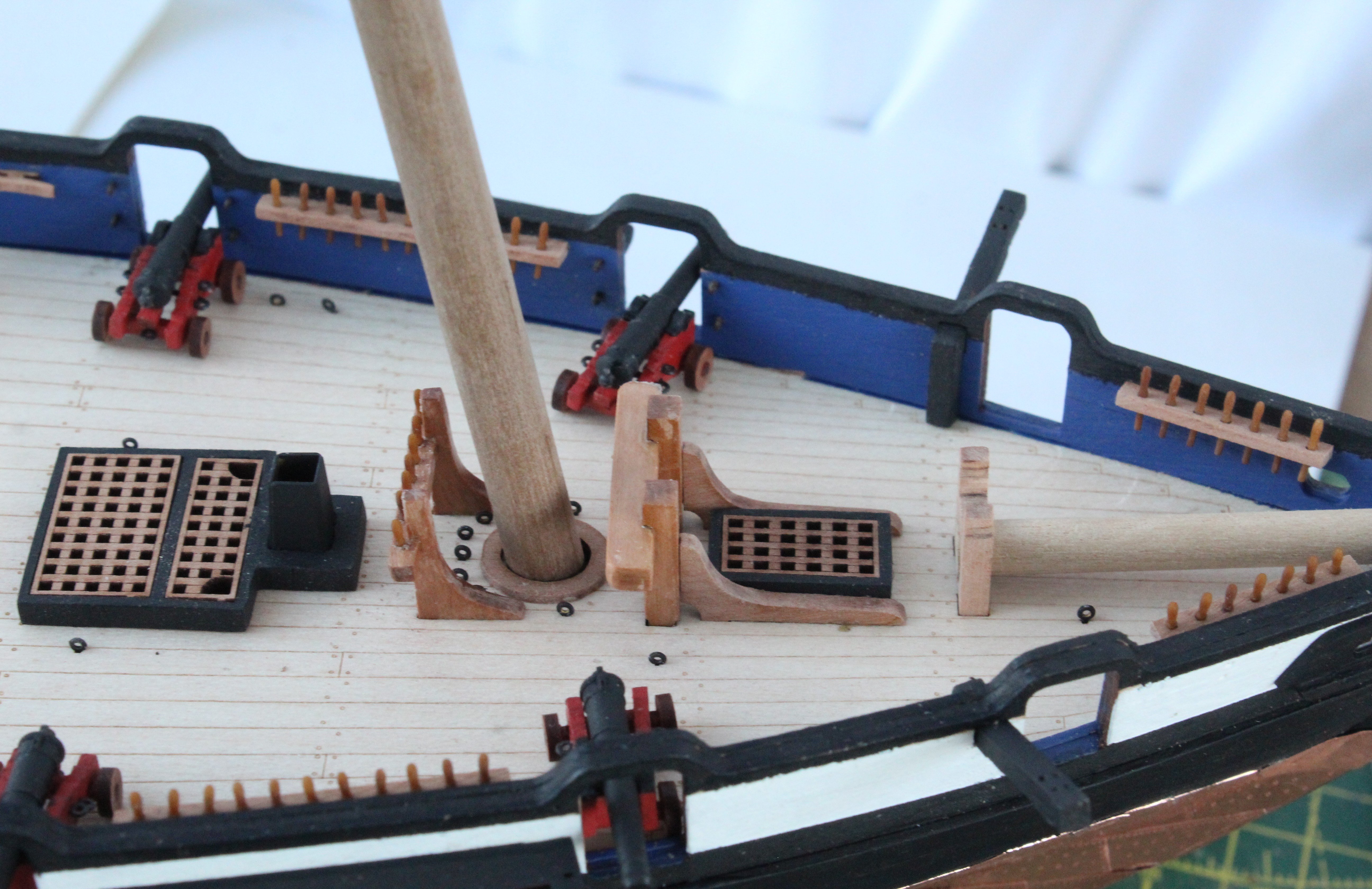
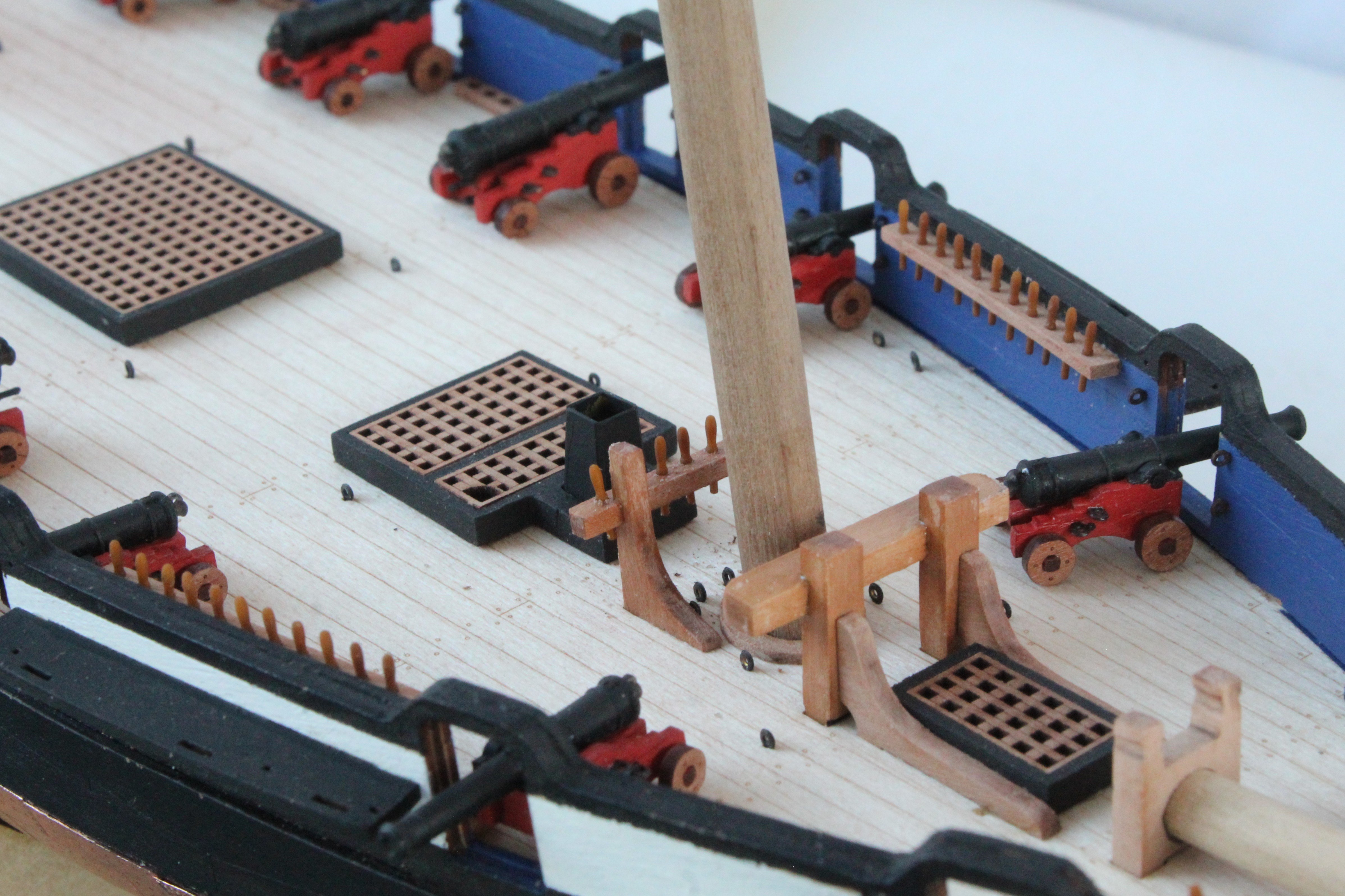
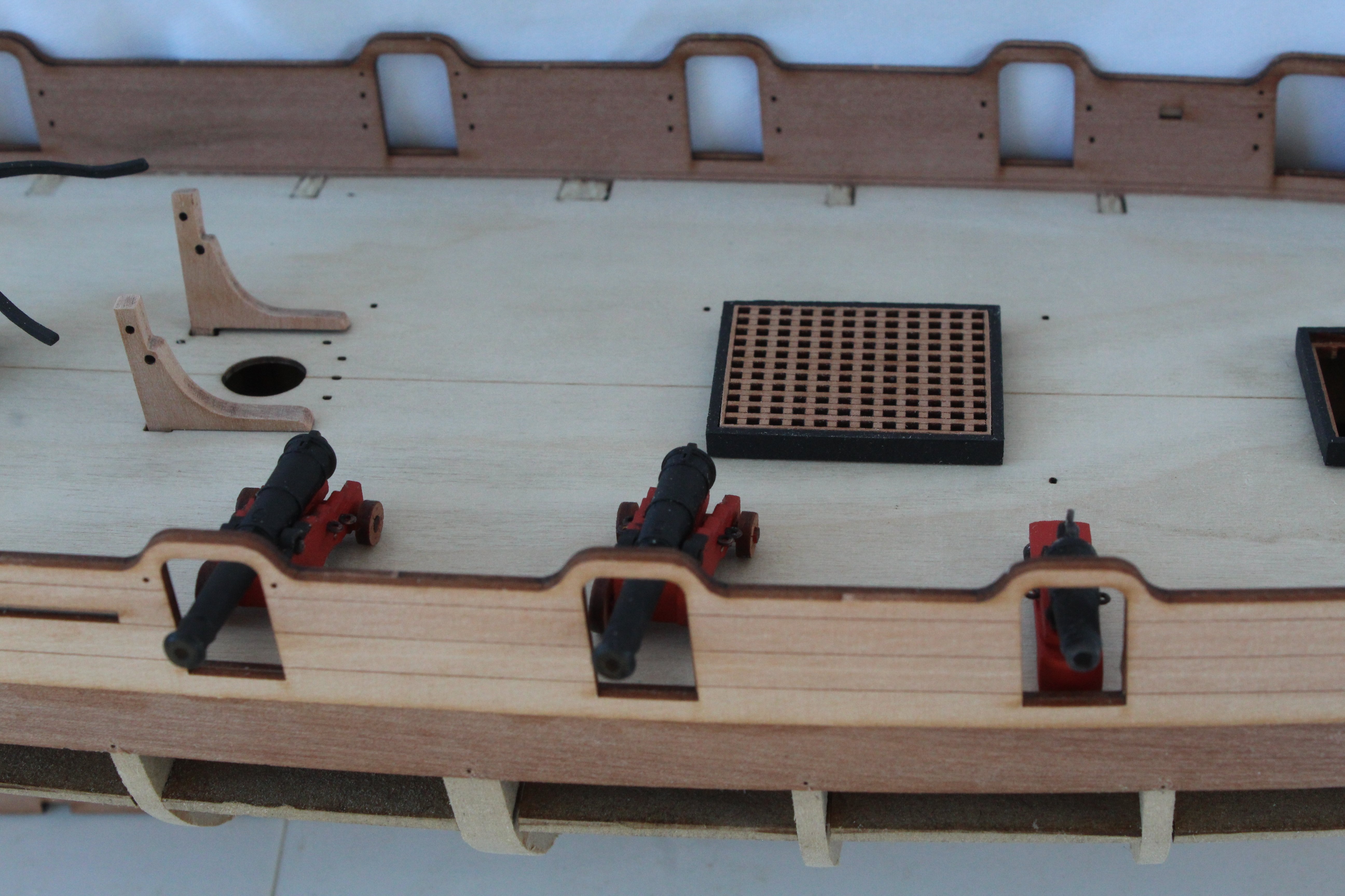
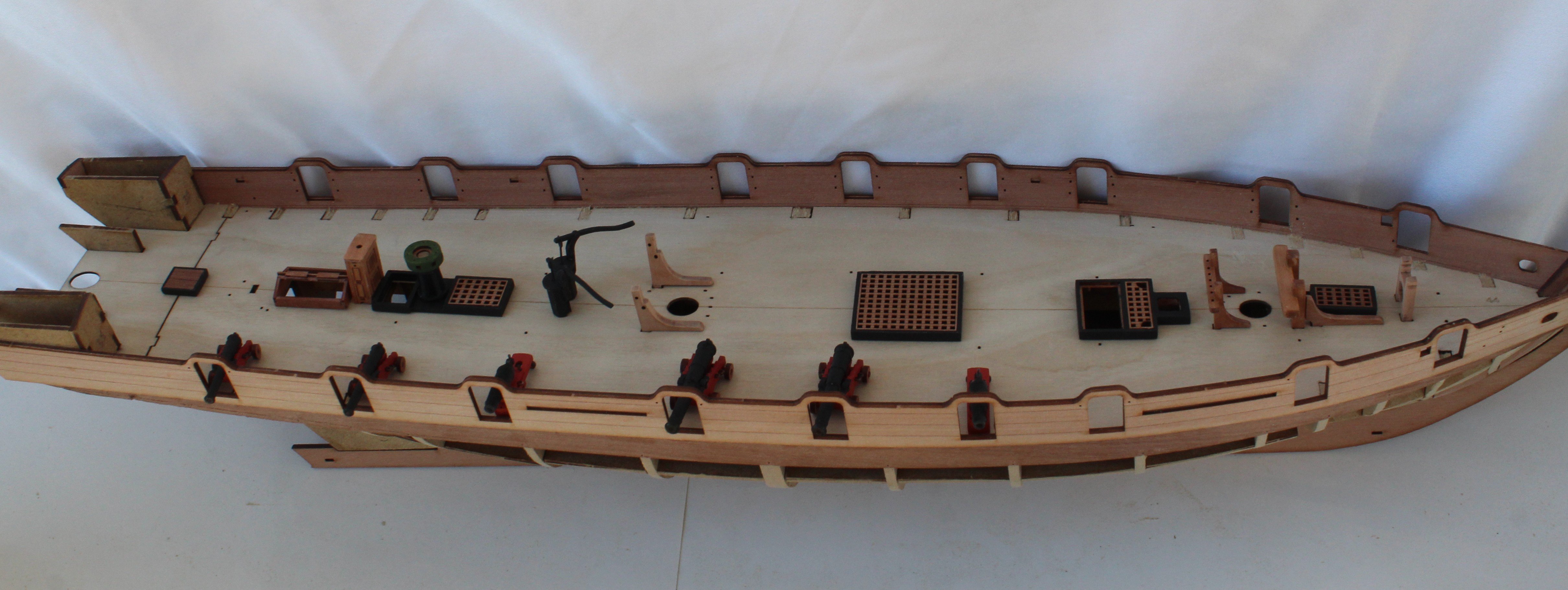
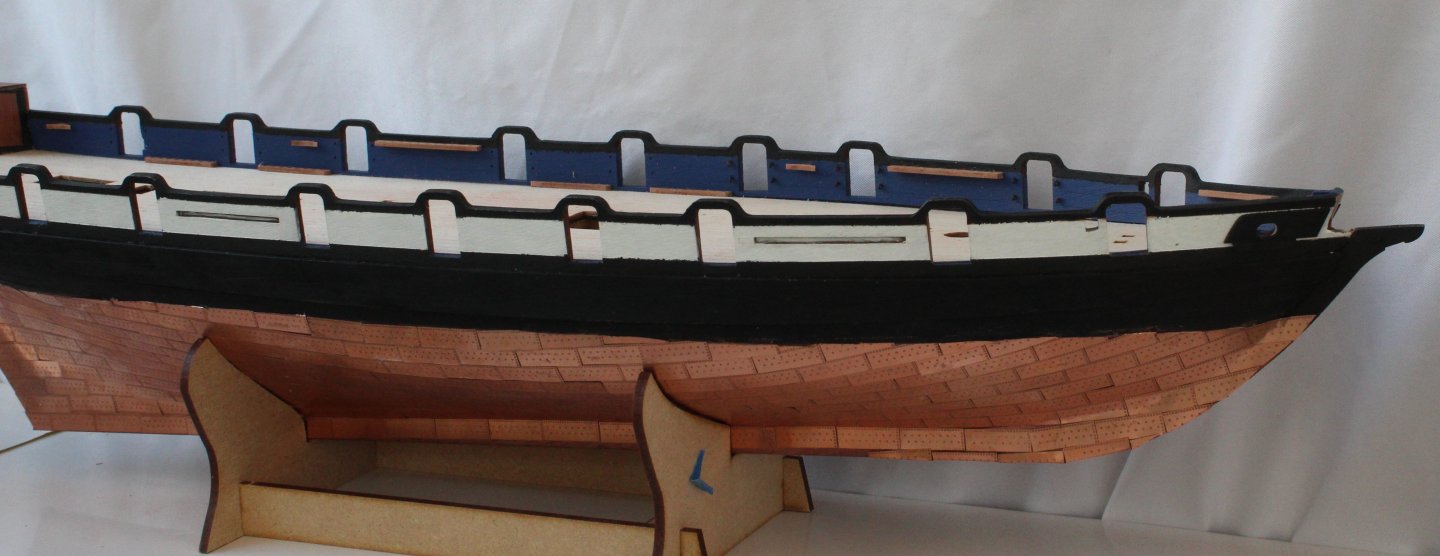
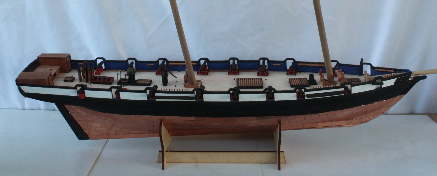
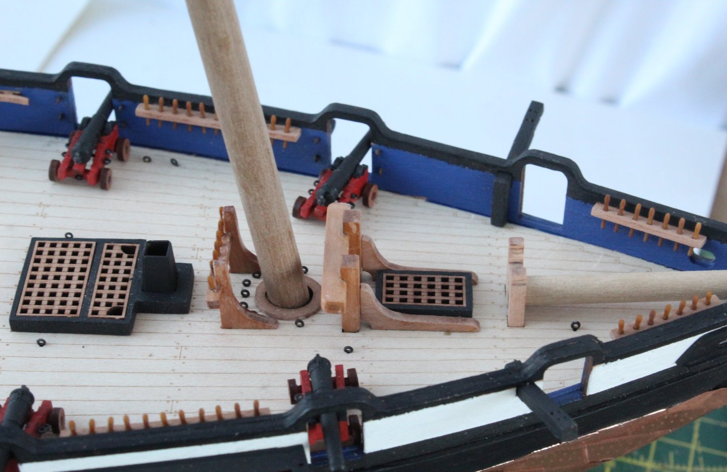
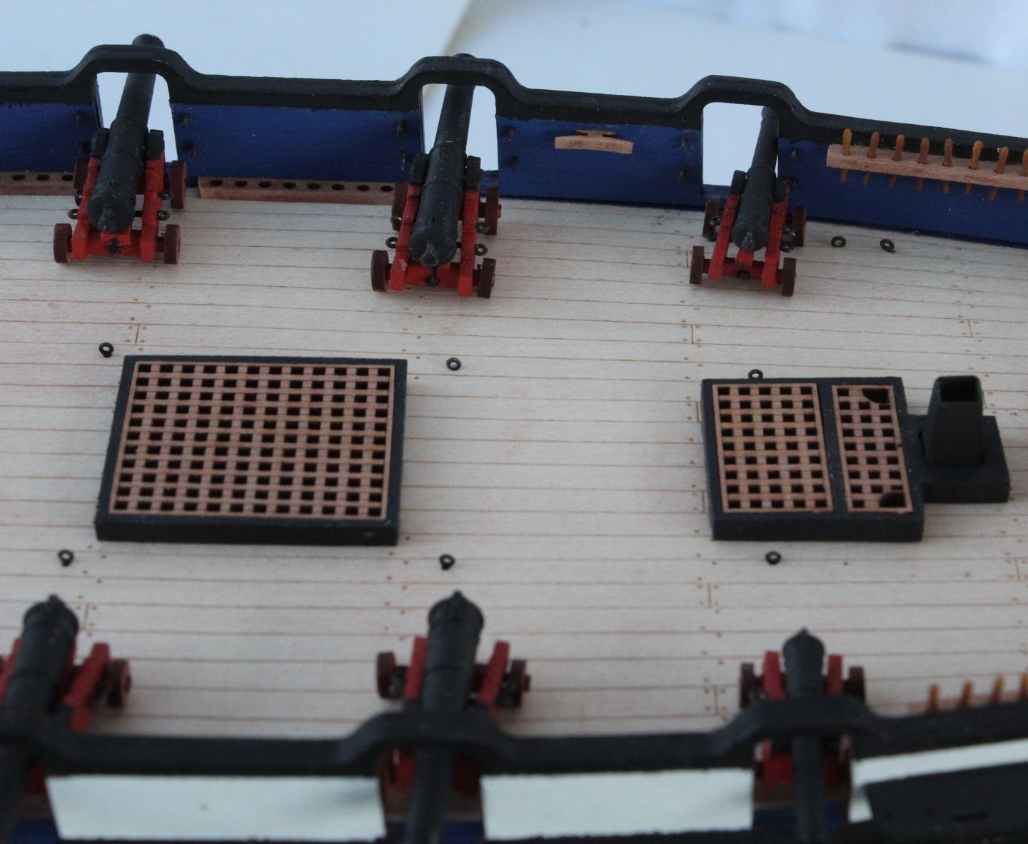
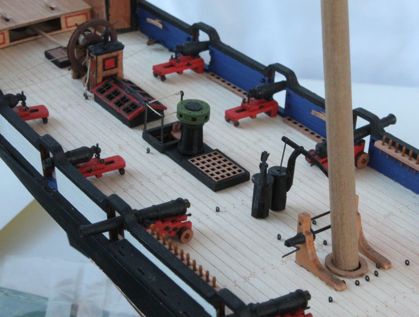
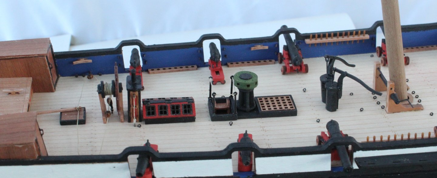
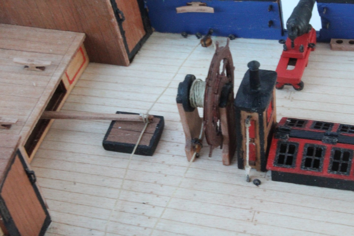
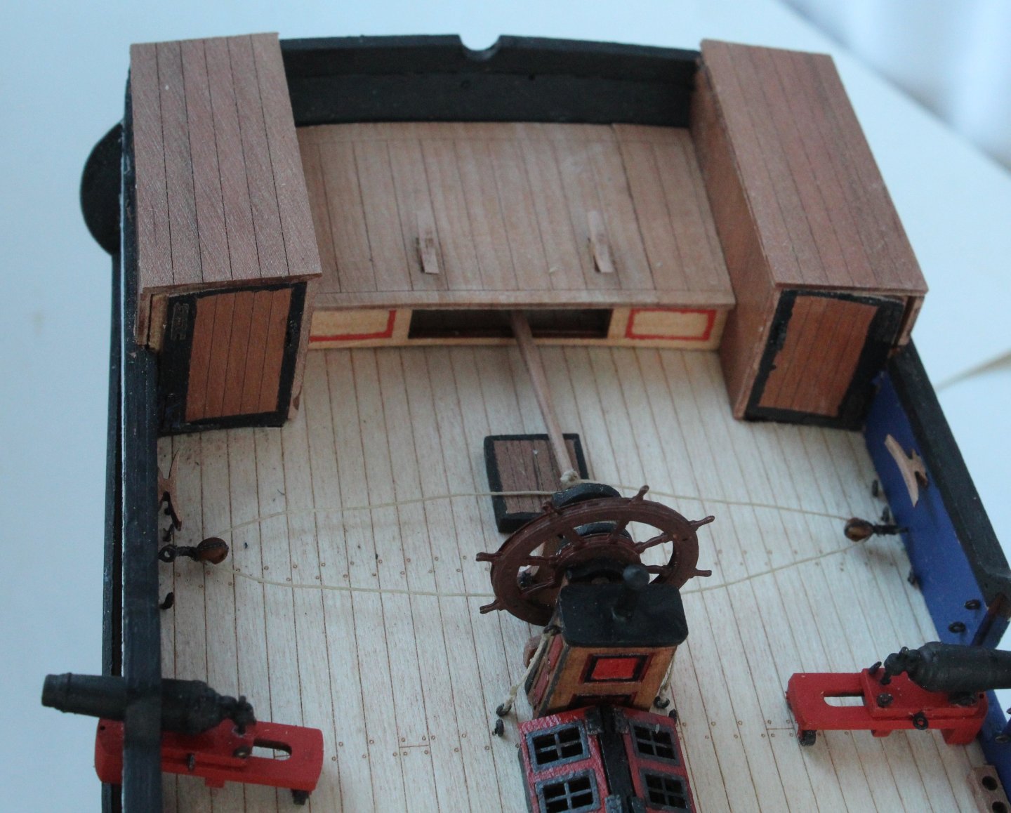
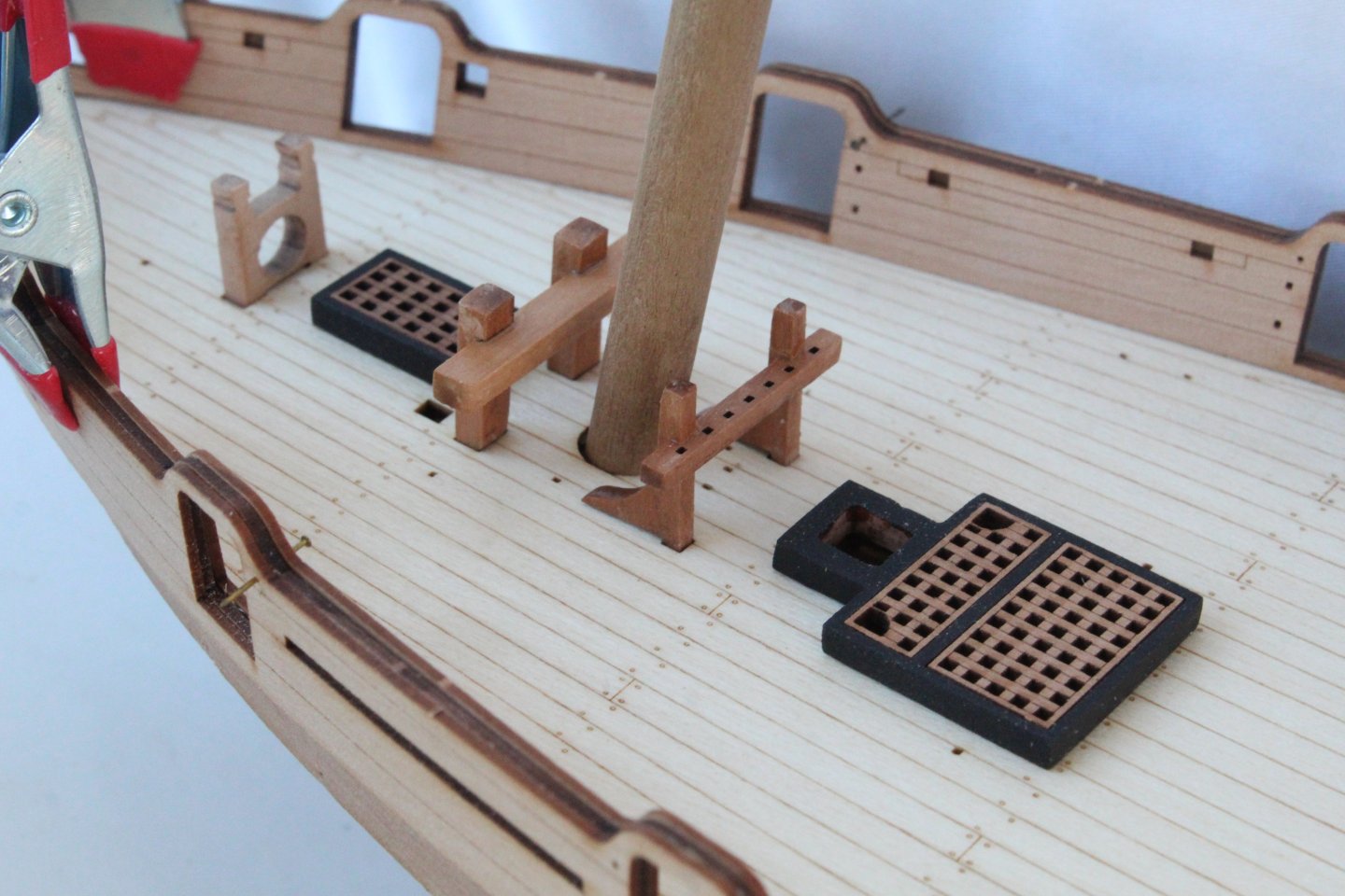
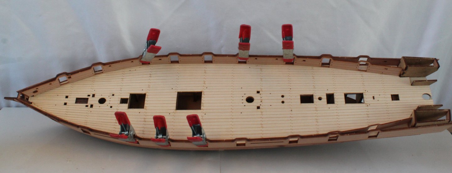
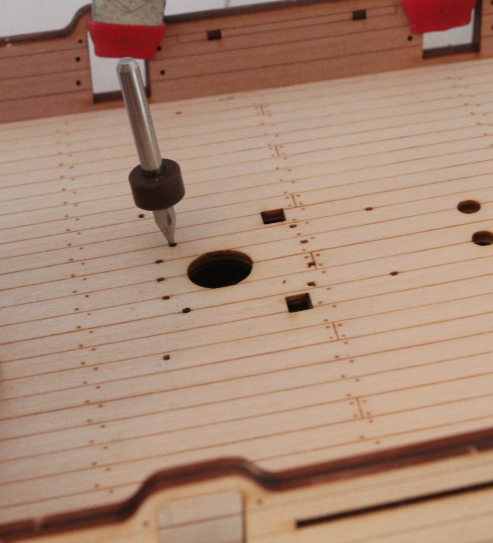
I will not be doing much more on this build for the foreseeable future as I will undertaking a commission build (for my daughter-in law) of Duchess of Kingston, when the kit I have ordered arrives from Vanguard Models. I will start a build log for the new build once the kit has arrived. The following is an update on my Grecian progress. Copper plating has been completed. I have not made a great job of it, especially around the bow. With the copper plating completed I then added the previously built deck items. I really like the look of the Syren belaying pins but I am concerned they may break when securing rigging to them as I have already broken a few. The companionway, binnacle and ships wheel rigging have been added. The cannons and carronades have only be placed on the deck in the following photos as I still deciding on the armament arrangement for my build. At the moment will probably go with the arrangement shown in the ensuring photos. My next task will be to add the cannon balls to the racks and to add the deadeyes / strops & chainplates to the channels. I will also add the hawse rope and anchors before moving on to the DOK build. I also plan to make the main and fore masts (if time permits), as I have already made the crosstrees for them. Plus I have also built the bowsprit, jibboom and flying jibboom.


-
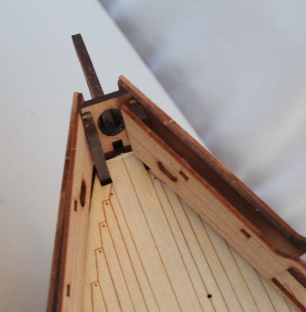
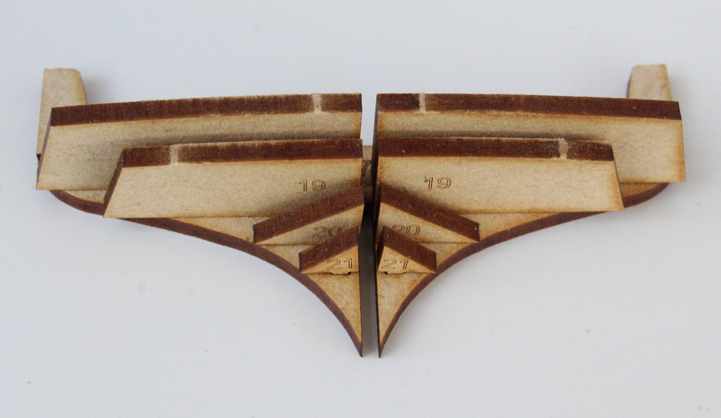
Whilst I wait for the copper plates to arrive I have moved on to the masts and bowsprit. The first task was to assemble the two cross trees, as shown below. Next I started work on the bowsprit. After cutting the dowel to length it was a case of making sure it fits. After the end cap and bees were added I then used my mini lathe to taper jibboom and flying jibboom. I also made a notch on the top of the jibboom ready for the lashing. All looks goods when they were test fitted. Two pairs of cleats were then added to the bowsprit. In the photo below the locating pin for the jibboom can also be seen. Finally the end sections of the bowsprit and jibboom were painted black. I will cover the detail with regards to adding the various rigging items (deadeye and thimbles) in a future post. The dolphin striker also will be added.


-
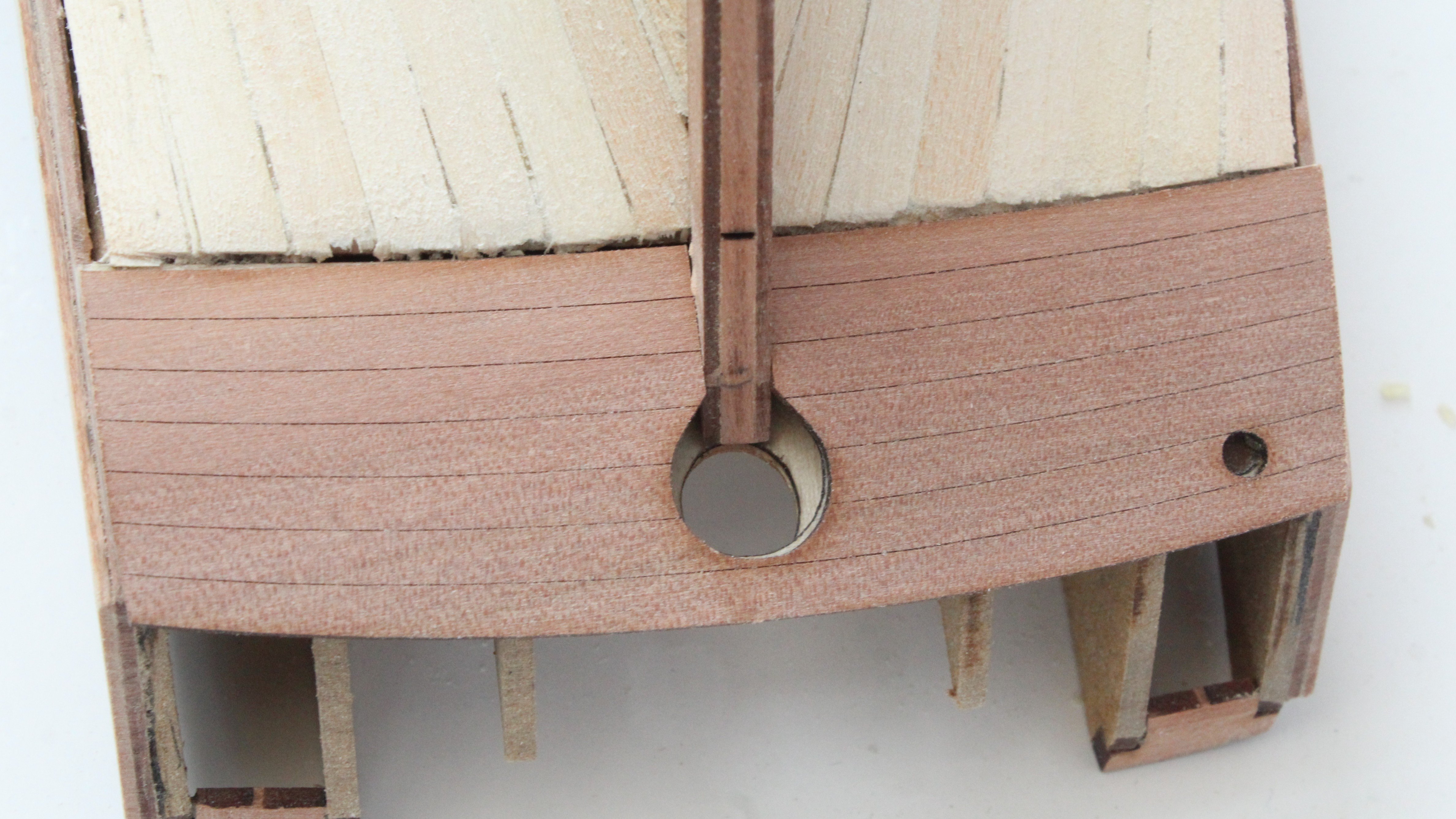
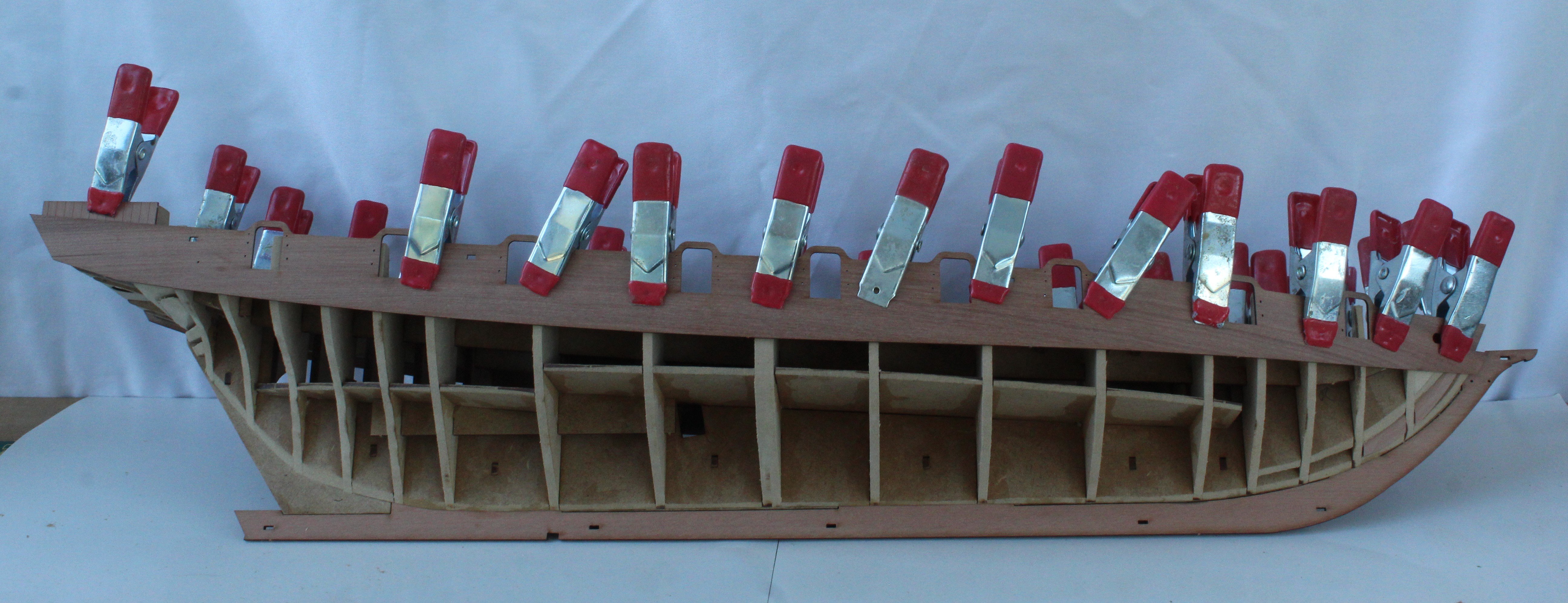
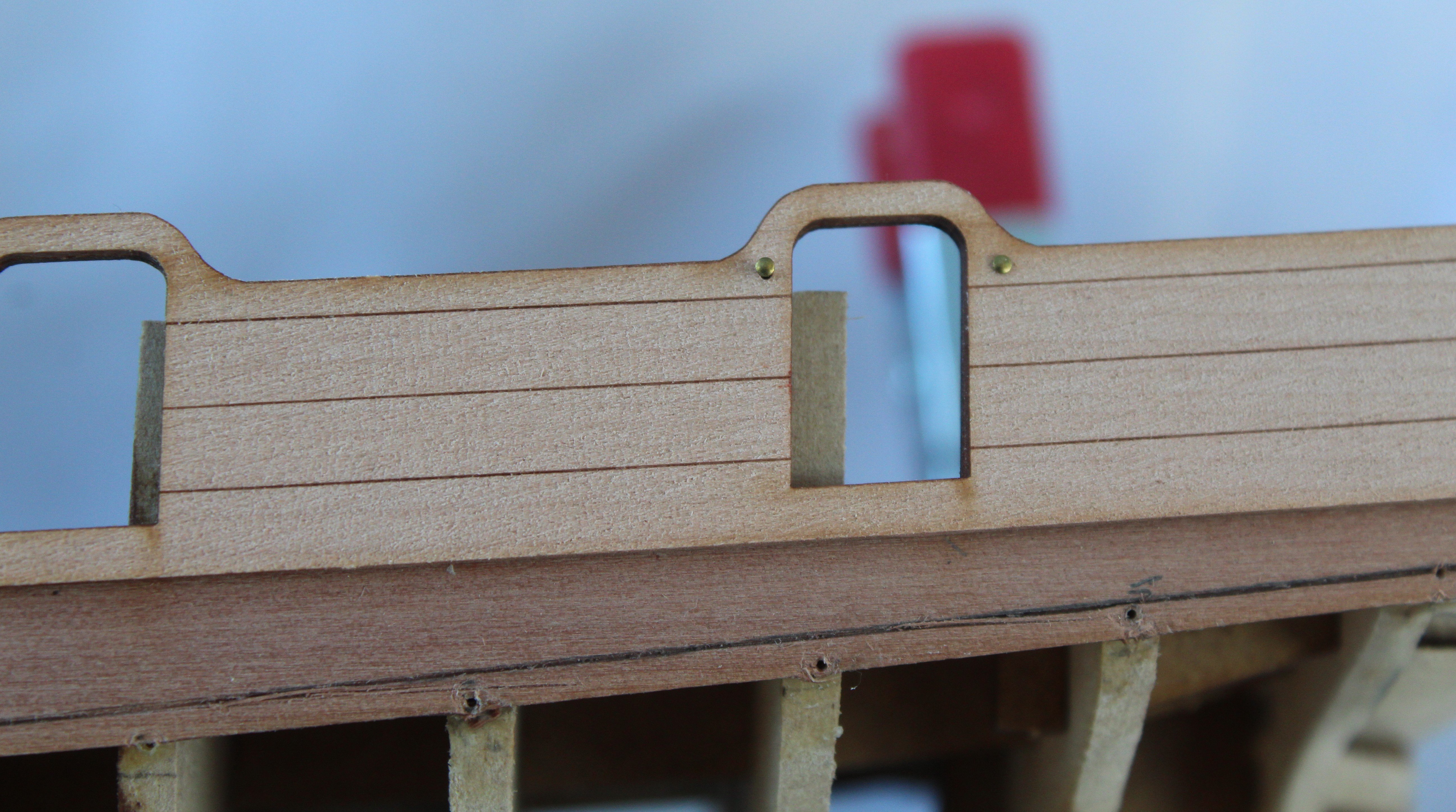
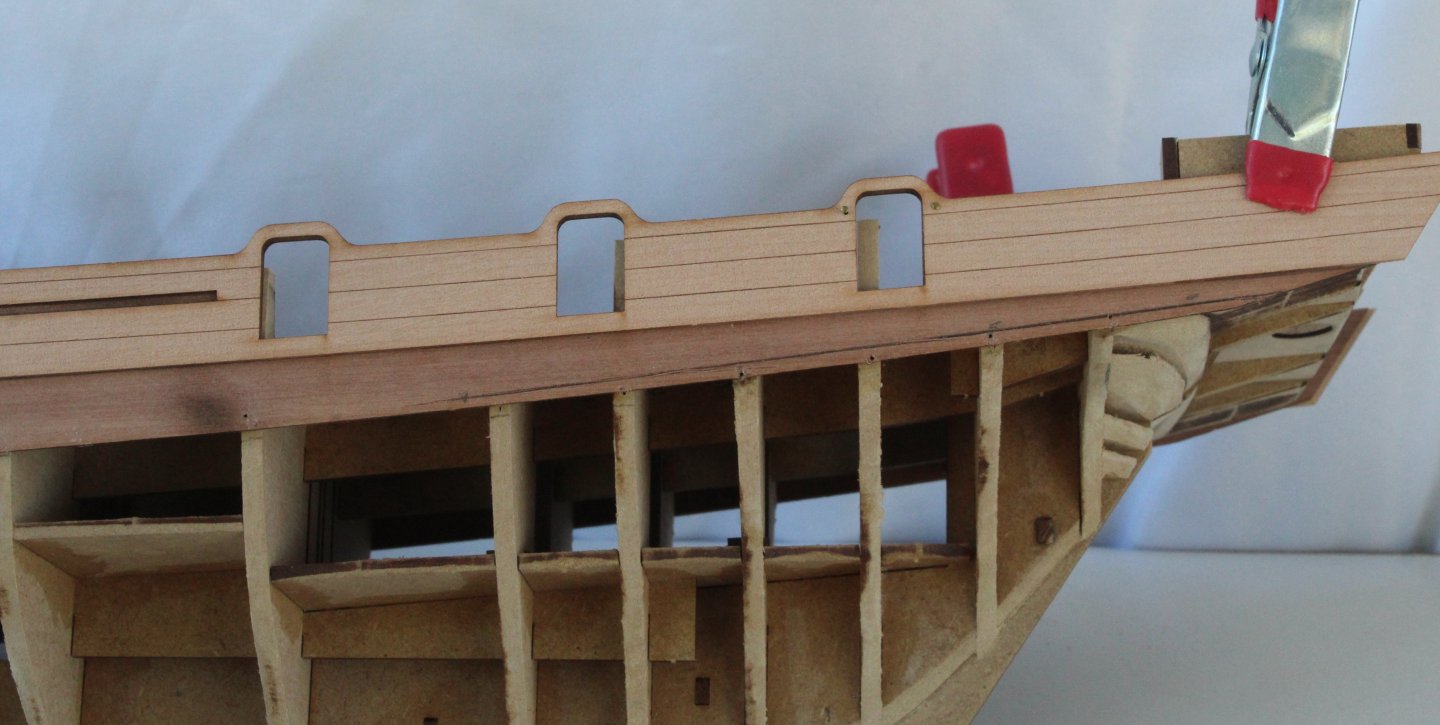
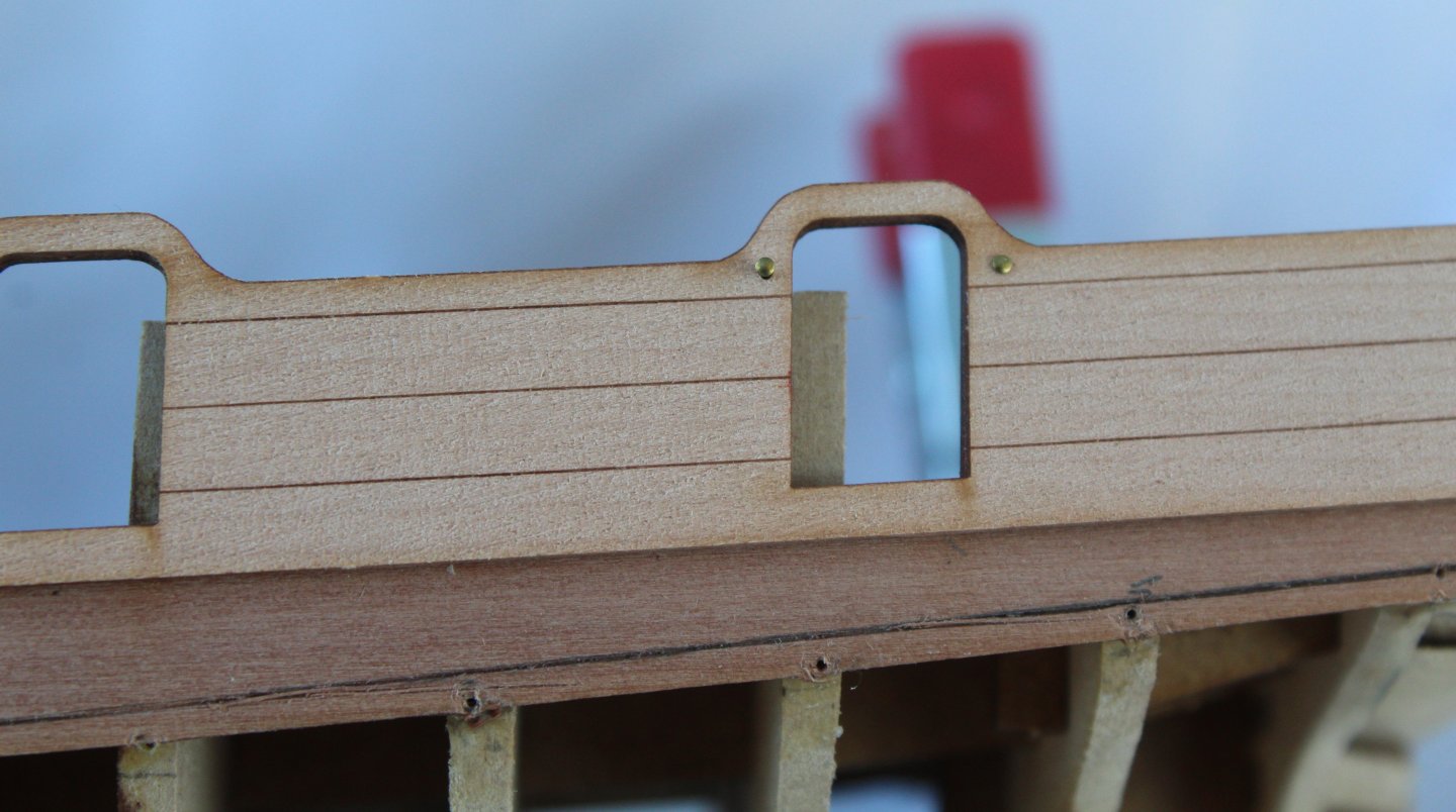
The hawse pattern, complete with bolster has now been painted and fitted. I am trying out some different belaying pins which are the same size of the PE belaying pins supplied with the kit, see photo below. They also fit in the locating holes provided on the kit supplied belay pin racks without any modification. The real test will come when rigging lines are belayed to these pins to see if they are strong enough. If not I can revert back to the kit supplied pins. The belaying racks, 3 per side, have now been glued in place and I do really like the look of the belaying pins. The shot garland racks have also been glued in place, four per side, along with the cleats. Next the channels were painted and test fitted. I plan to glue these parts in place after the hull has been copper plated. Next it was time to start adding the various eyebolts required for the cannons and carronades. Finally, in preparation for starting the copper plating I have used a template to get the best fit for the stern post plates.


-
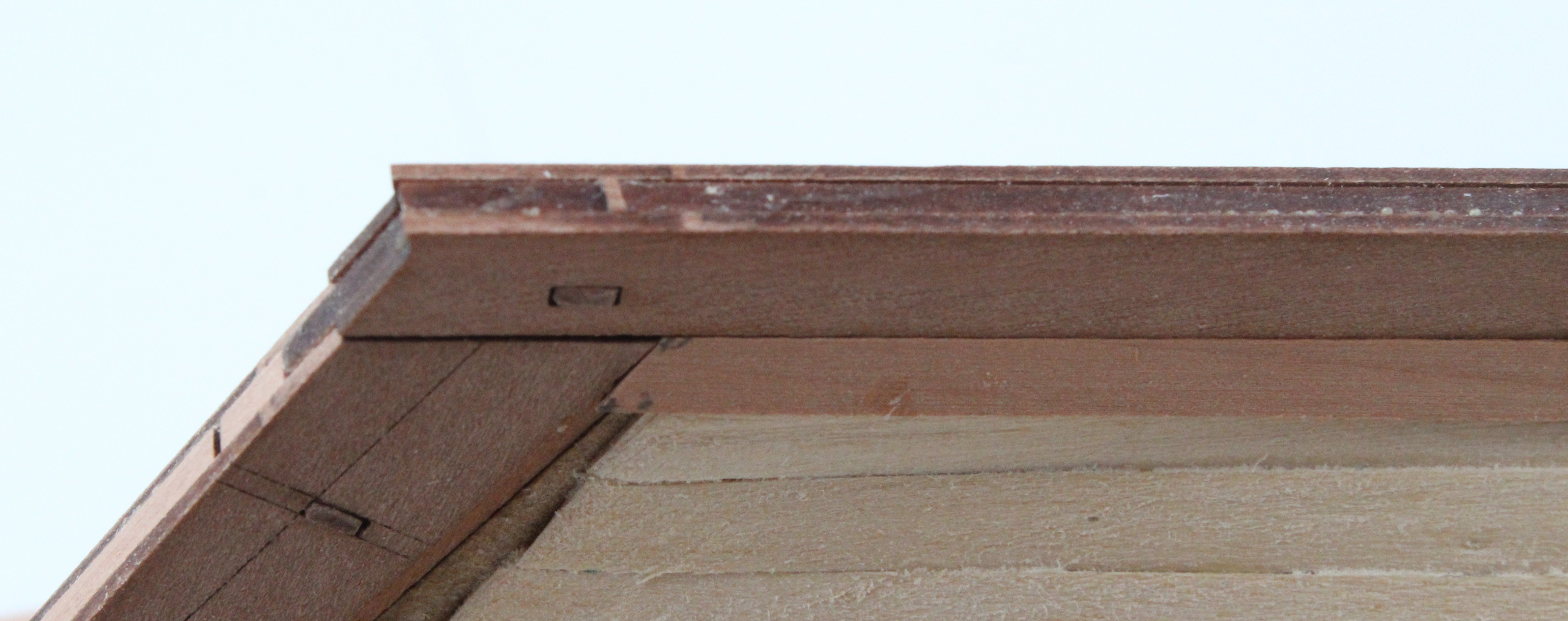
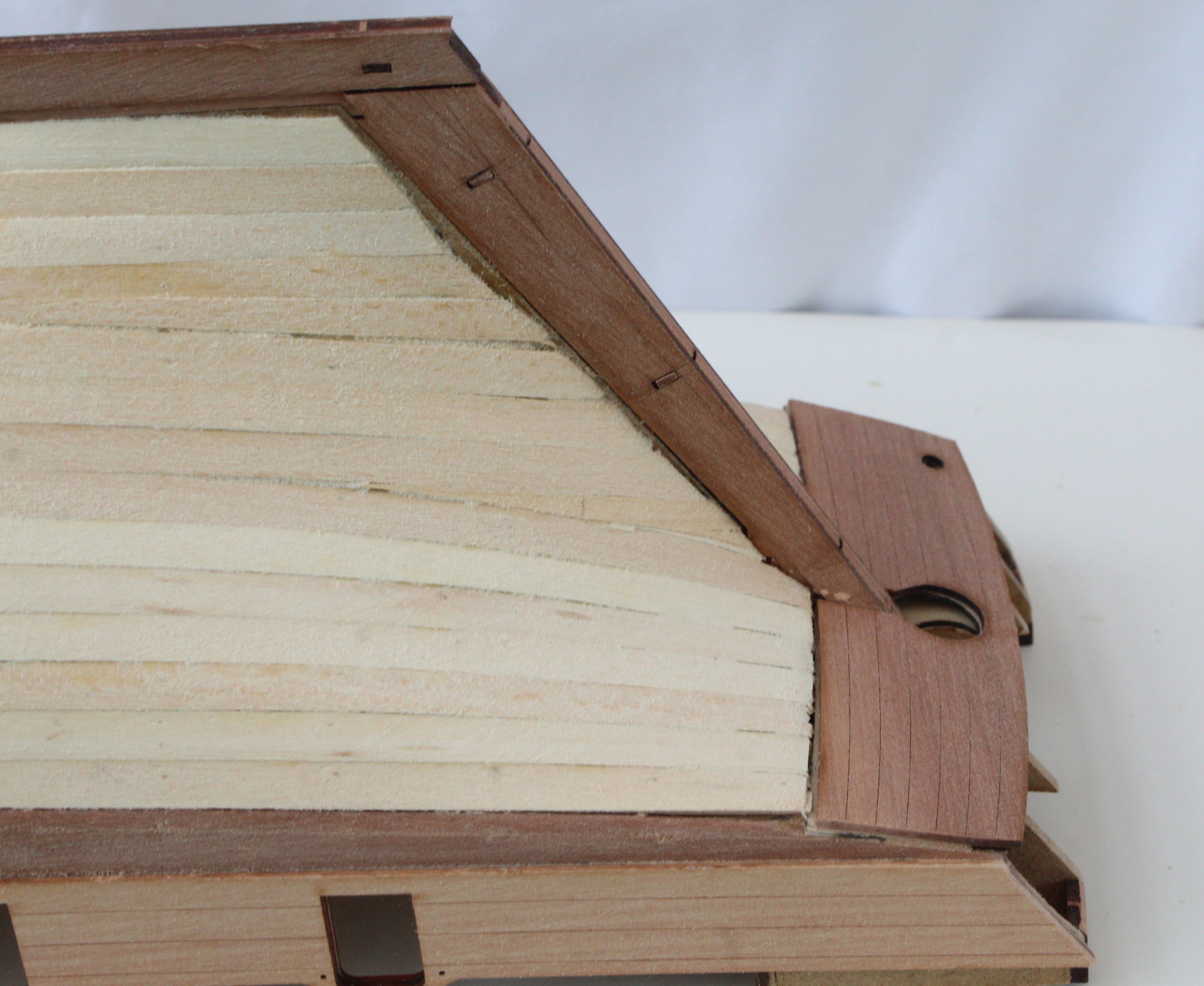
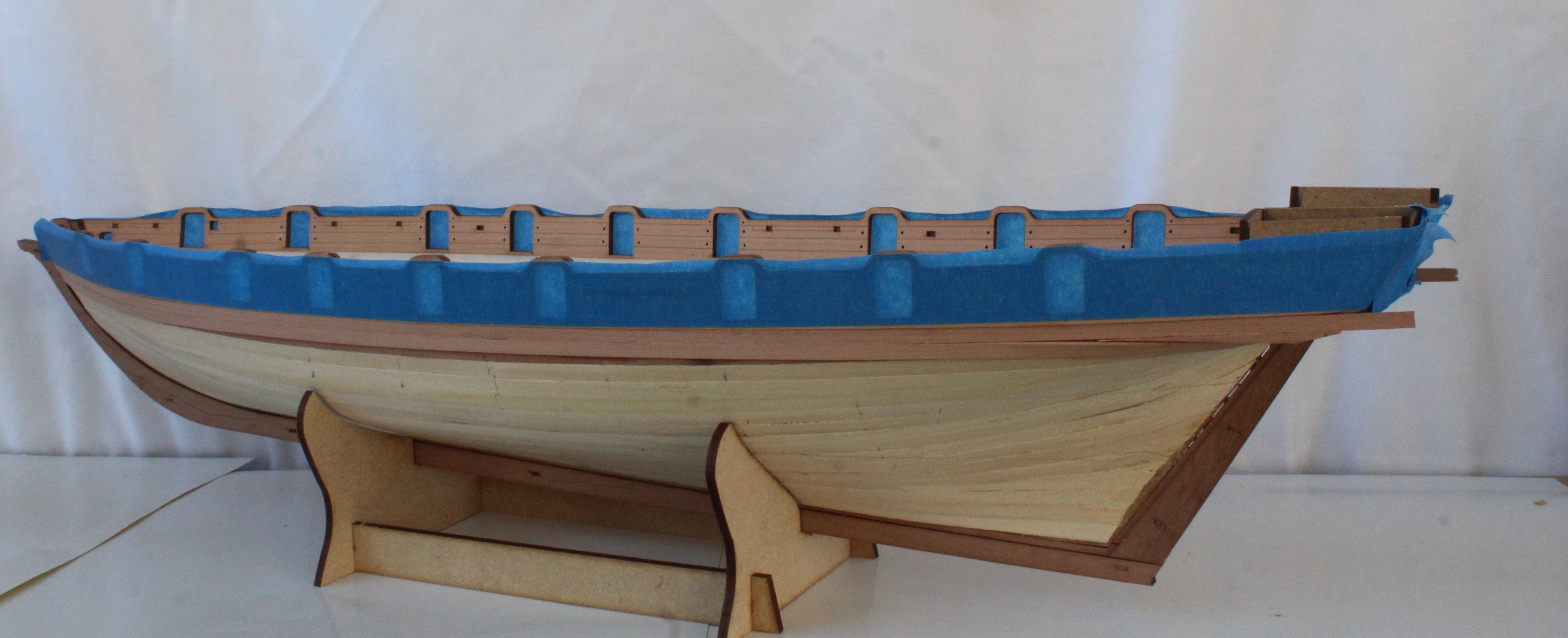
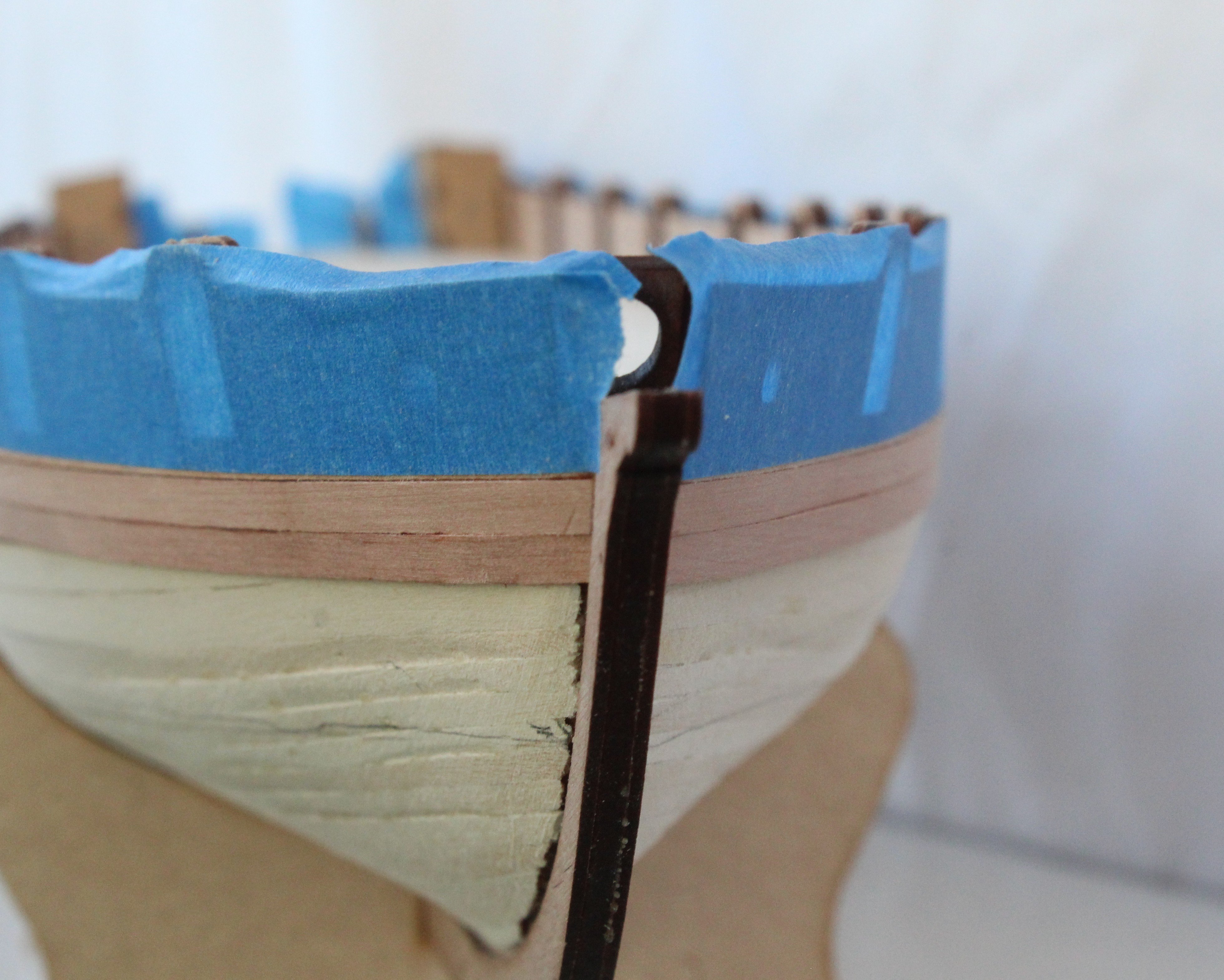
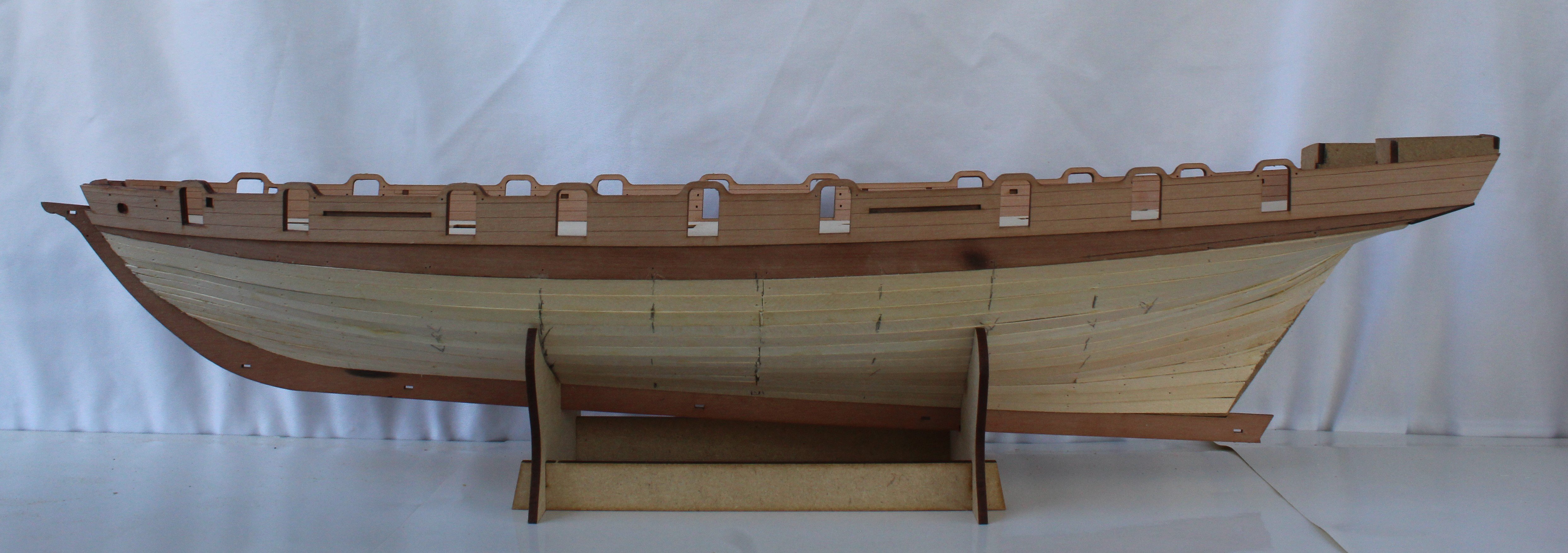
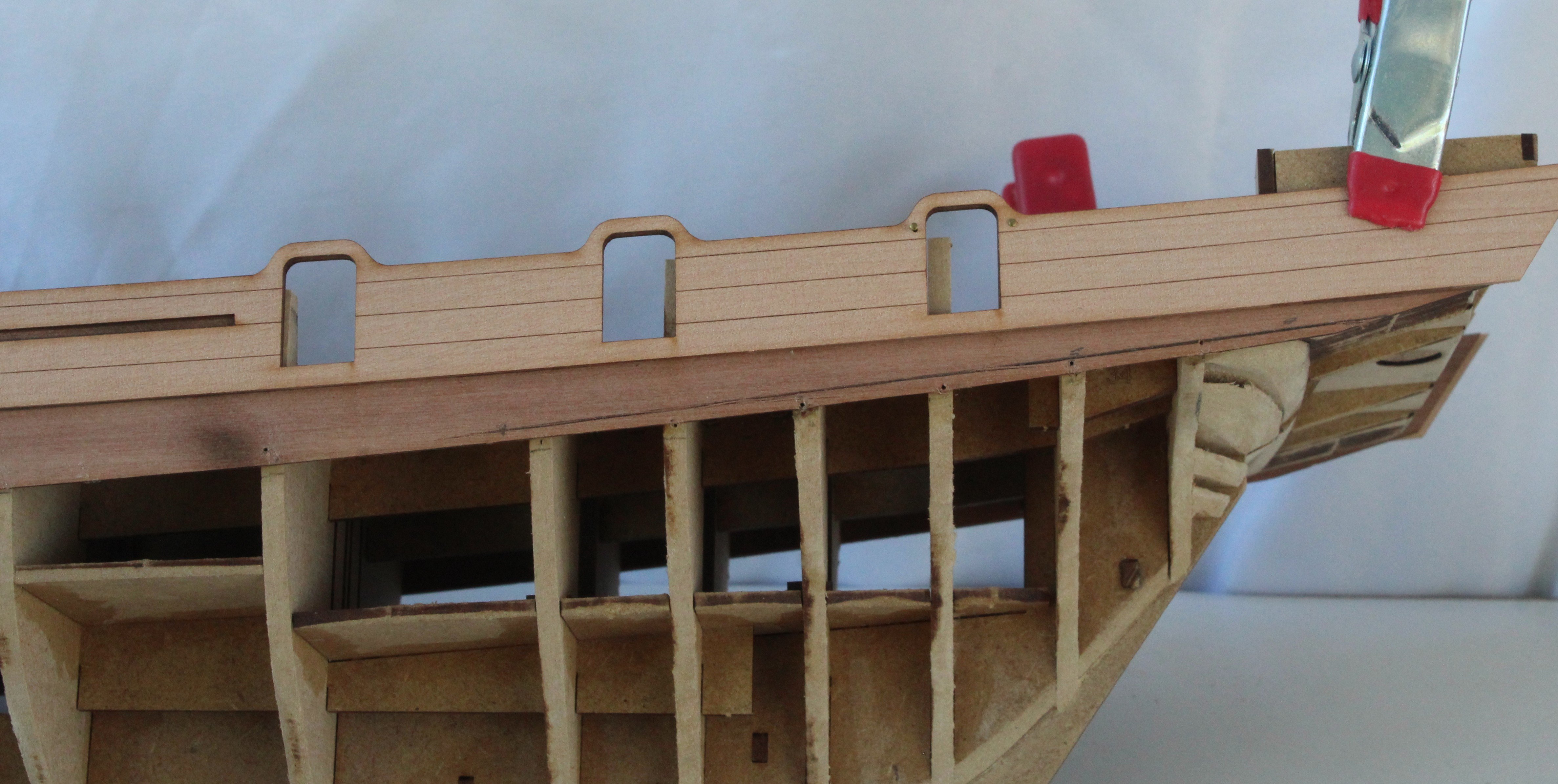
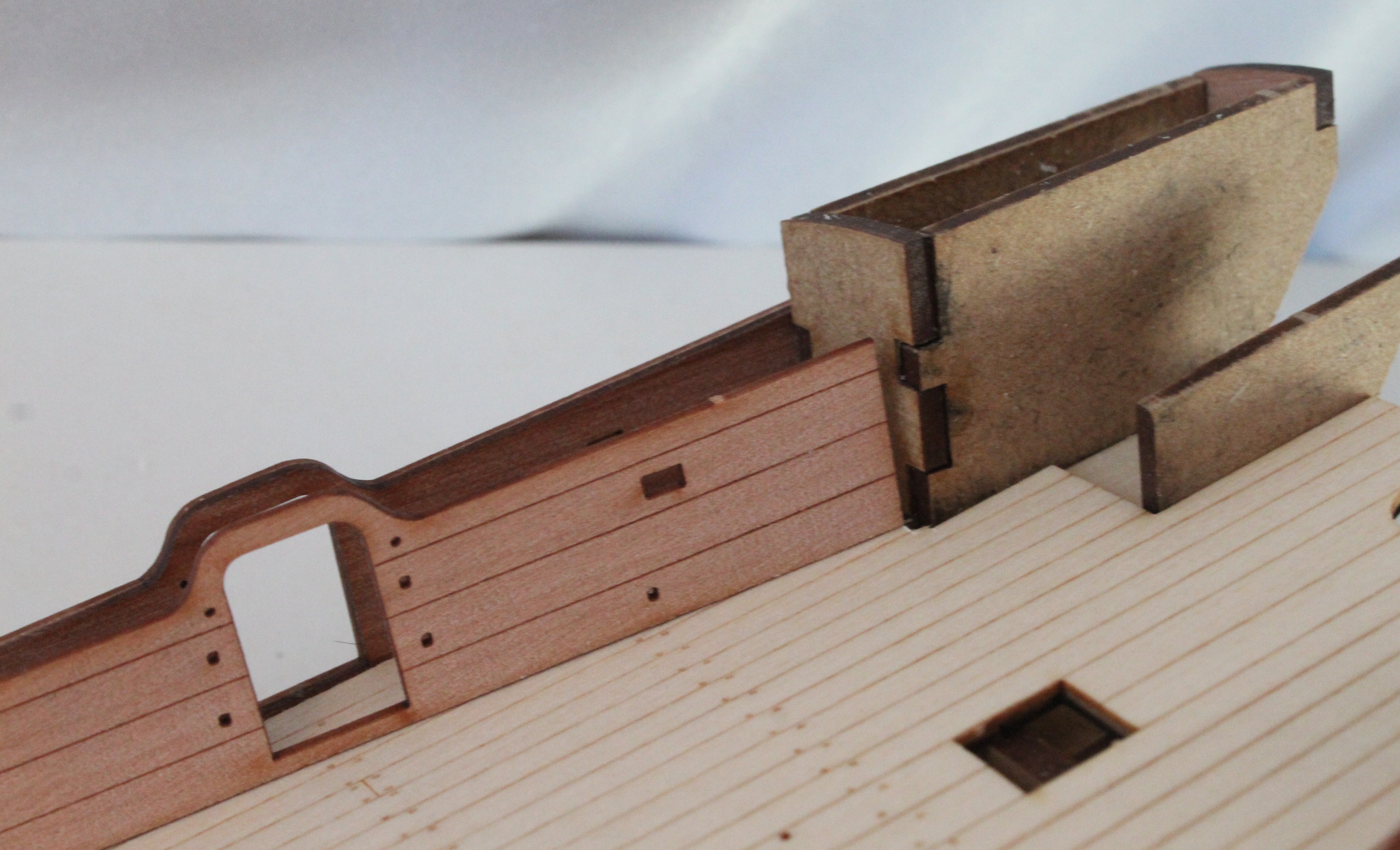
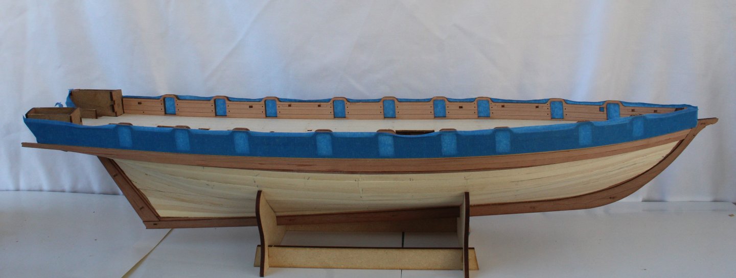
I have been working steadily on the Grecian build over the last few days but unfortunately I have not been taking many photo's. I have now completed the following tasks: a) The hull has been sanded smooth and painted. b) The wales have been added. c) The two rear cabins have been added. d) The outer stern counter pattern has been added e) The lower counter rails have been added f) The stern board (main and top) patterns have been added. I have gone against the build manual / prototype and opted to paint the inner bulwarks blue rather than green. I have also added a copper paint base below the water line. I will be fitting copper plates rather than using the kit supplied copper tape. The copper plates have been ordered and should arrive later this week. The following photo shows the current build statis Next is a picture of the rear cabins. I now wish I had not painted the outer surround of the cabin doors black but it is not a show stopper. I do like the red infill I added to the tiller housing front panel however. I have also test fitted the tiller housing canopy. The cleats have also been added to the inner bulwarks. Next is a picture of the stern. I am not totally happy with the joins between the various parts, but in the great scheme of the build this aspect will not really be visible when the model is completed. Also there is an outer pattern to add to the stern main board which will make thing look better, once fitted. Next is a photo showing the internal colour scheme. Finally I have tested fitted the channels and pin racks.


-
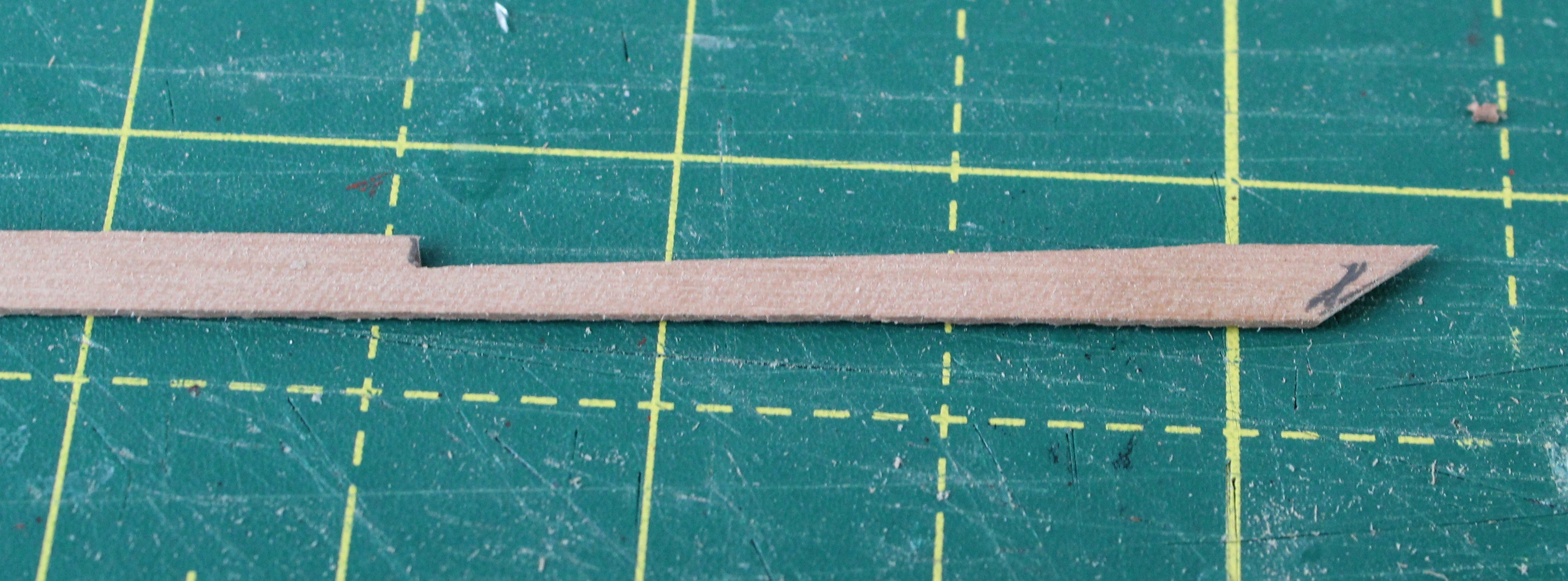
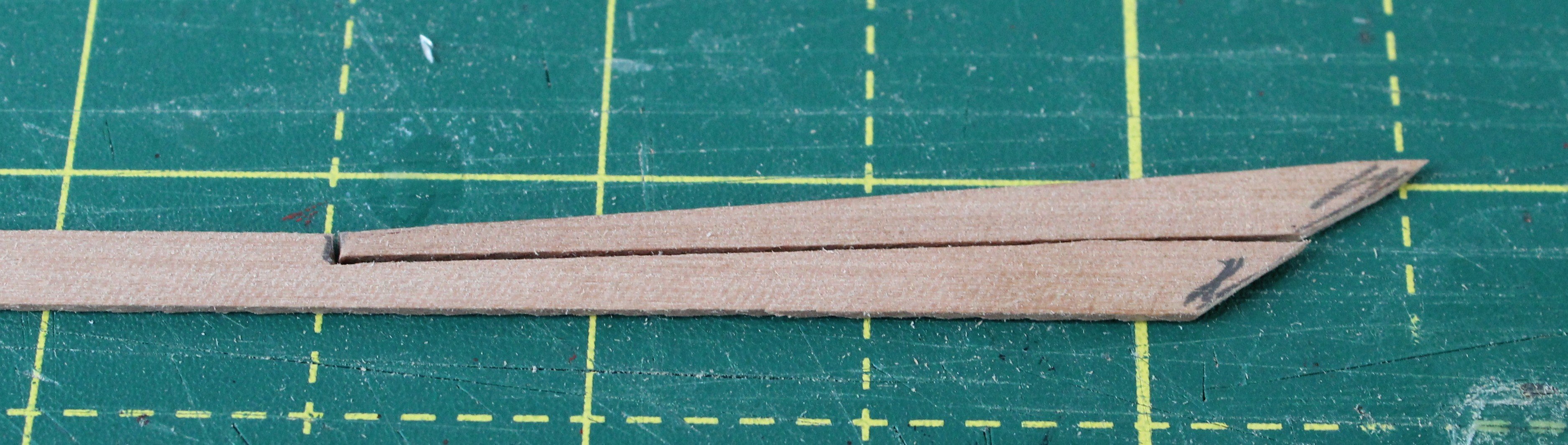
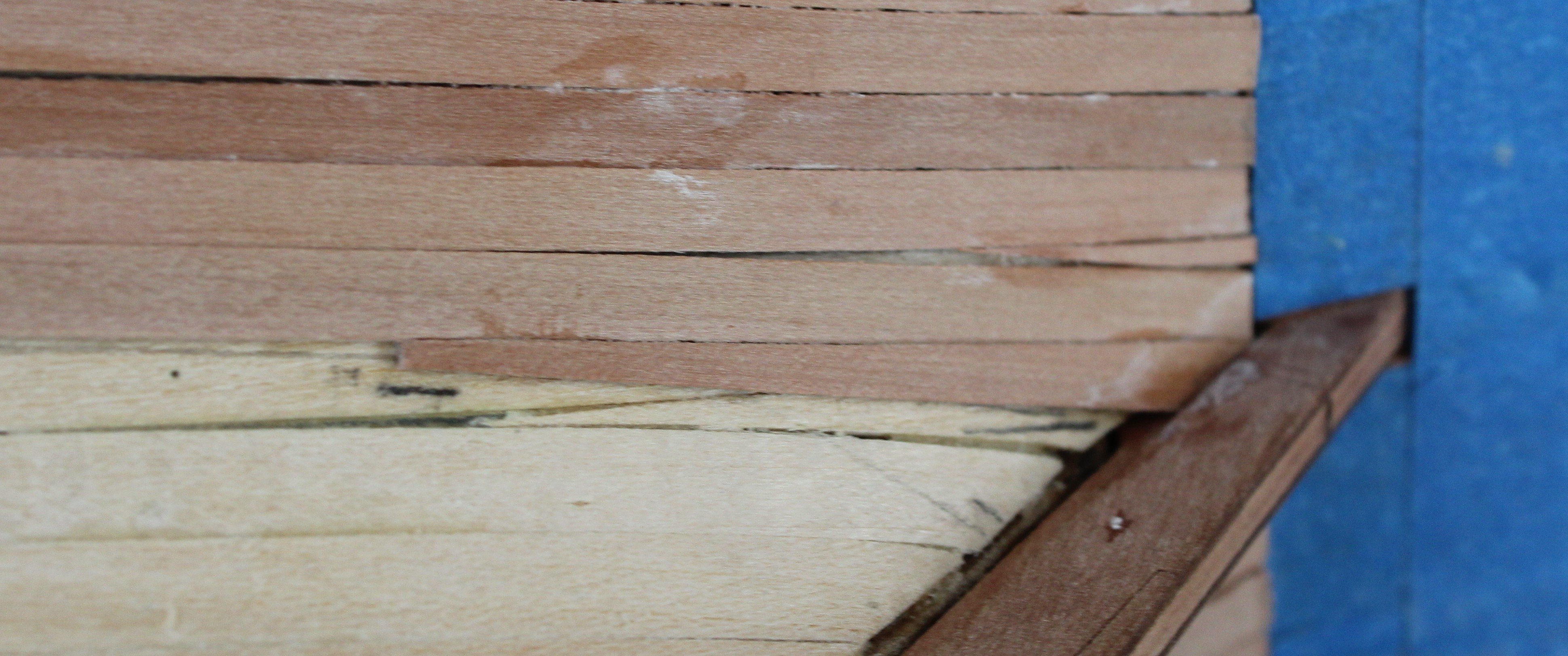
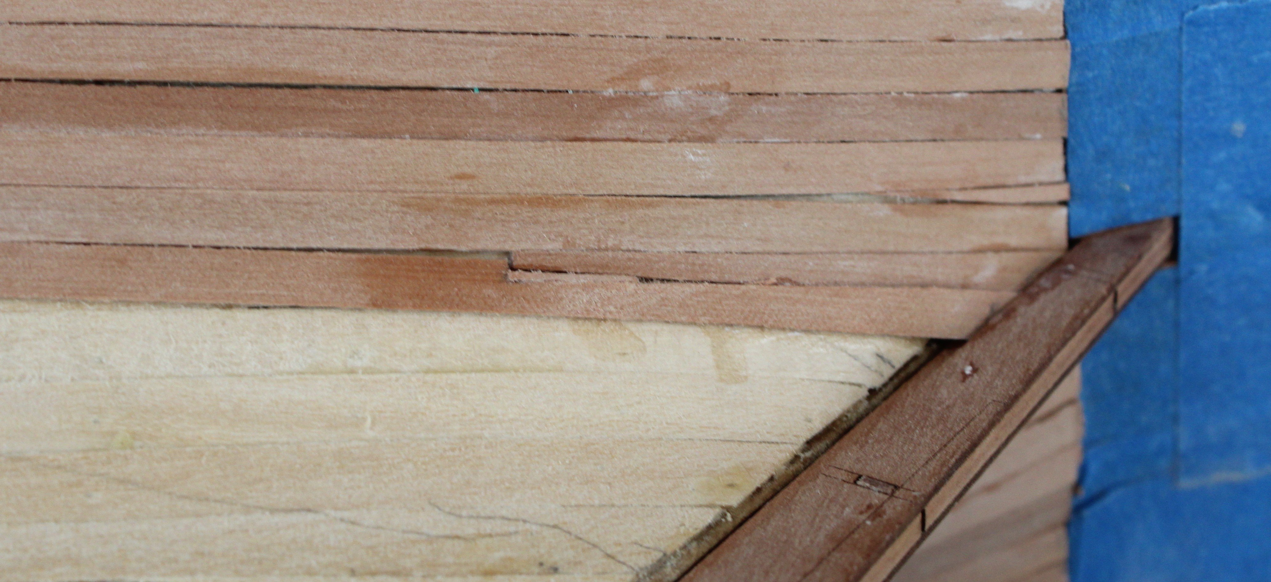
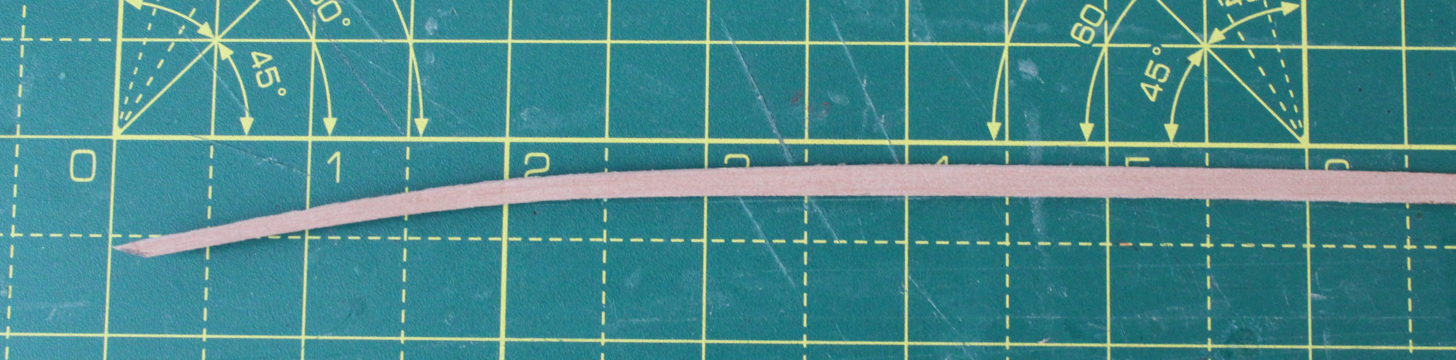
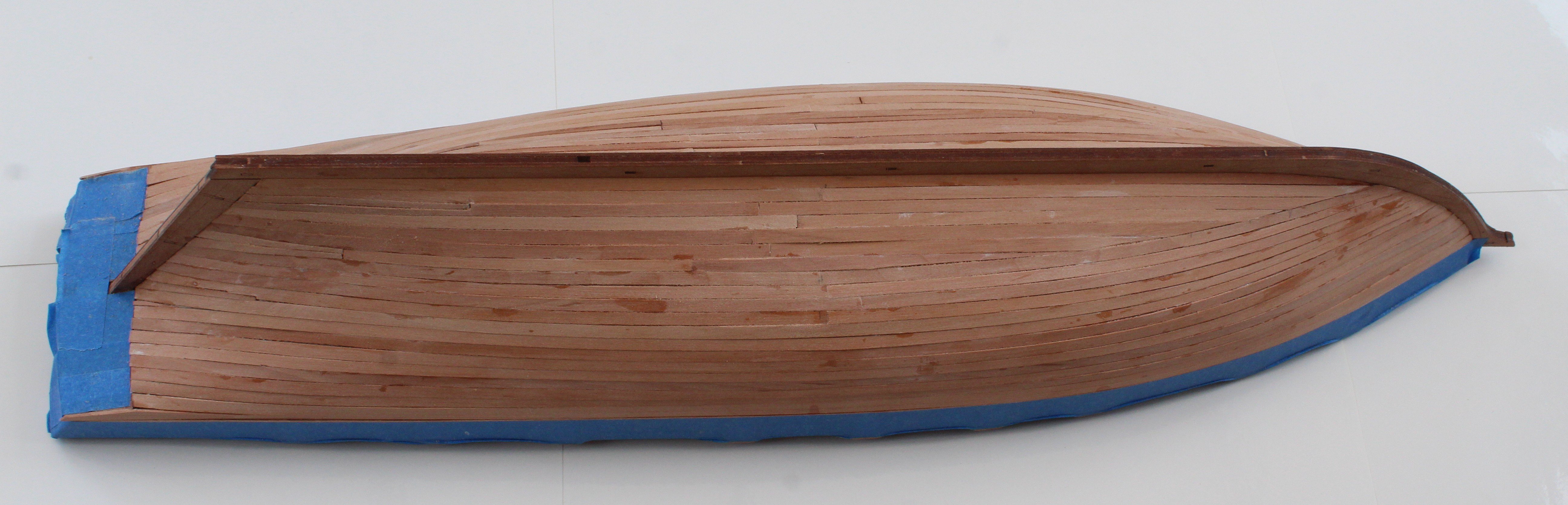
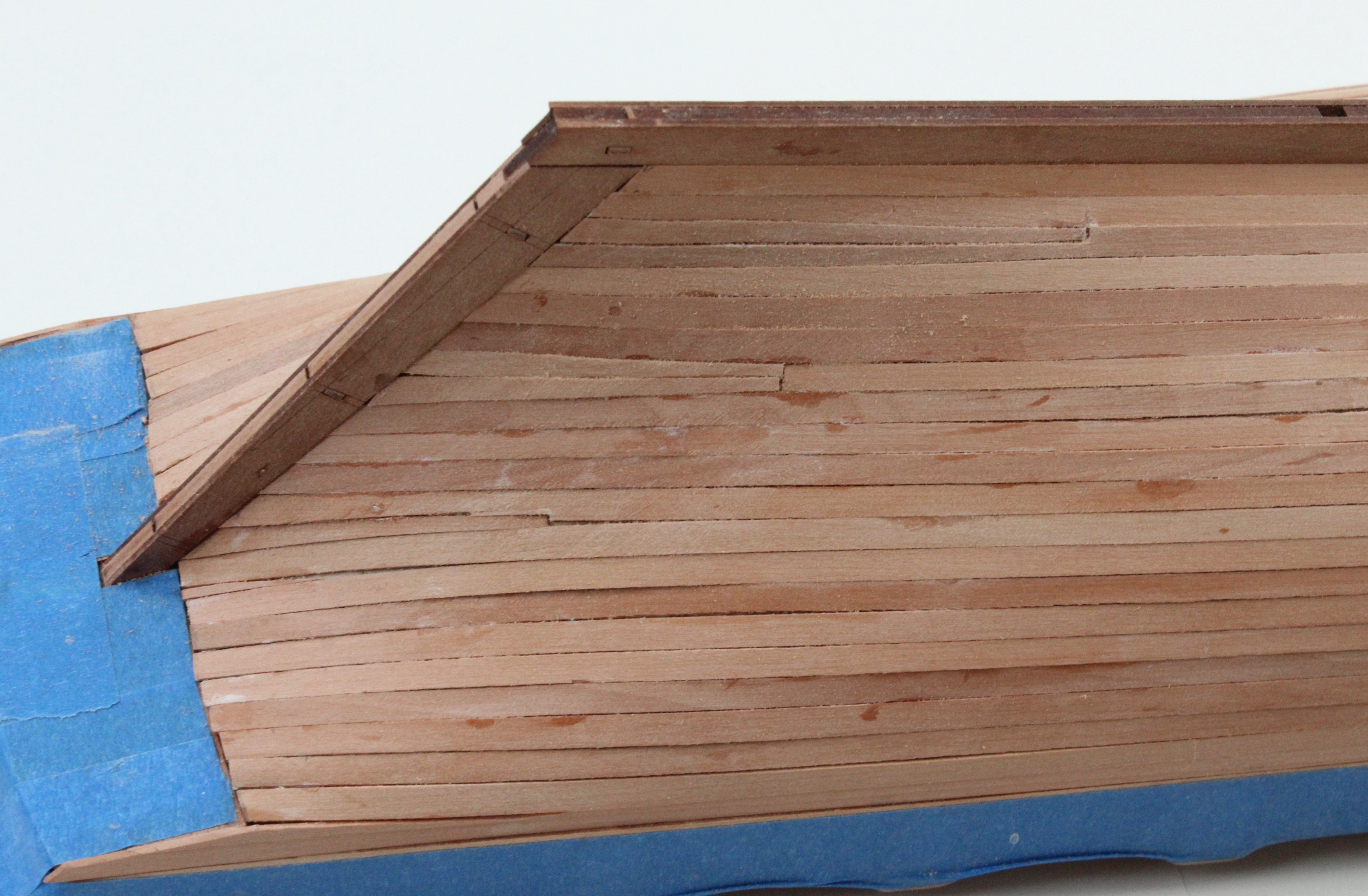
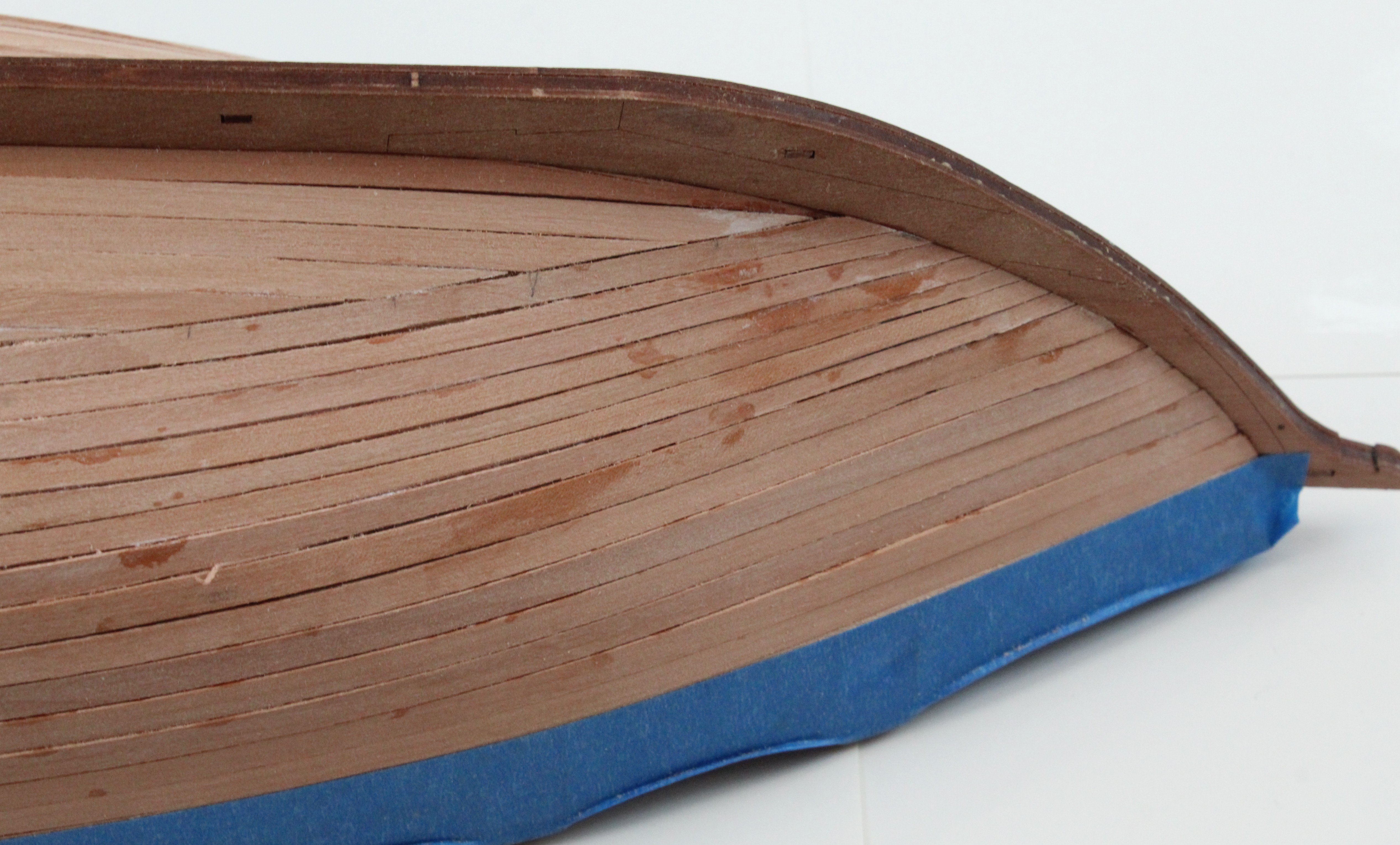
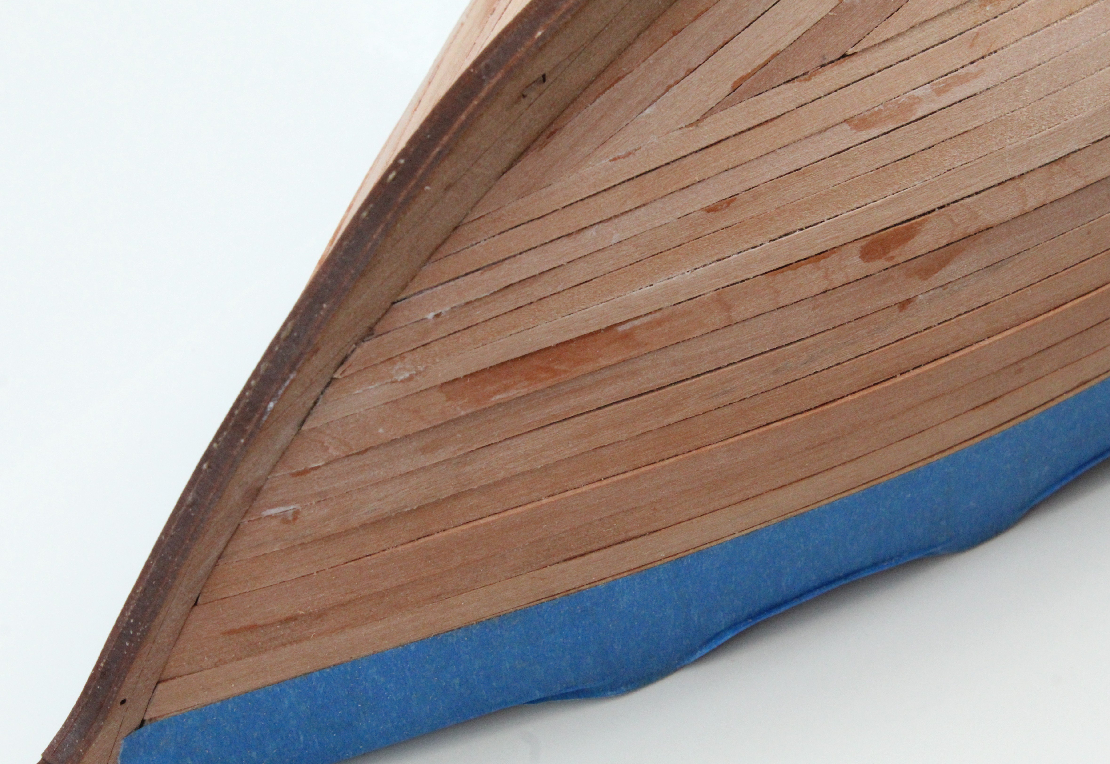
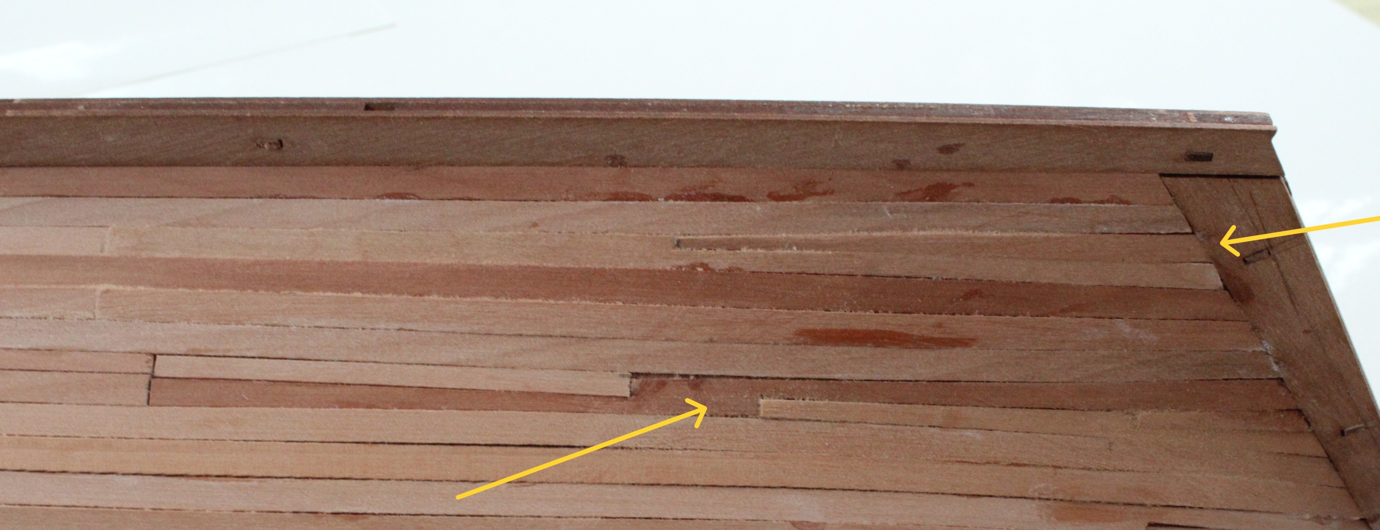
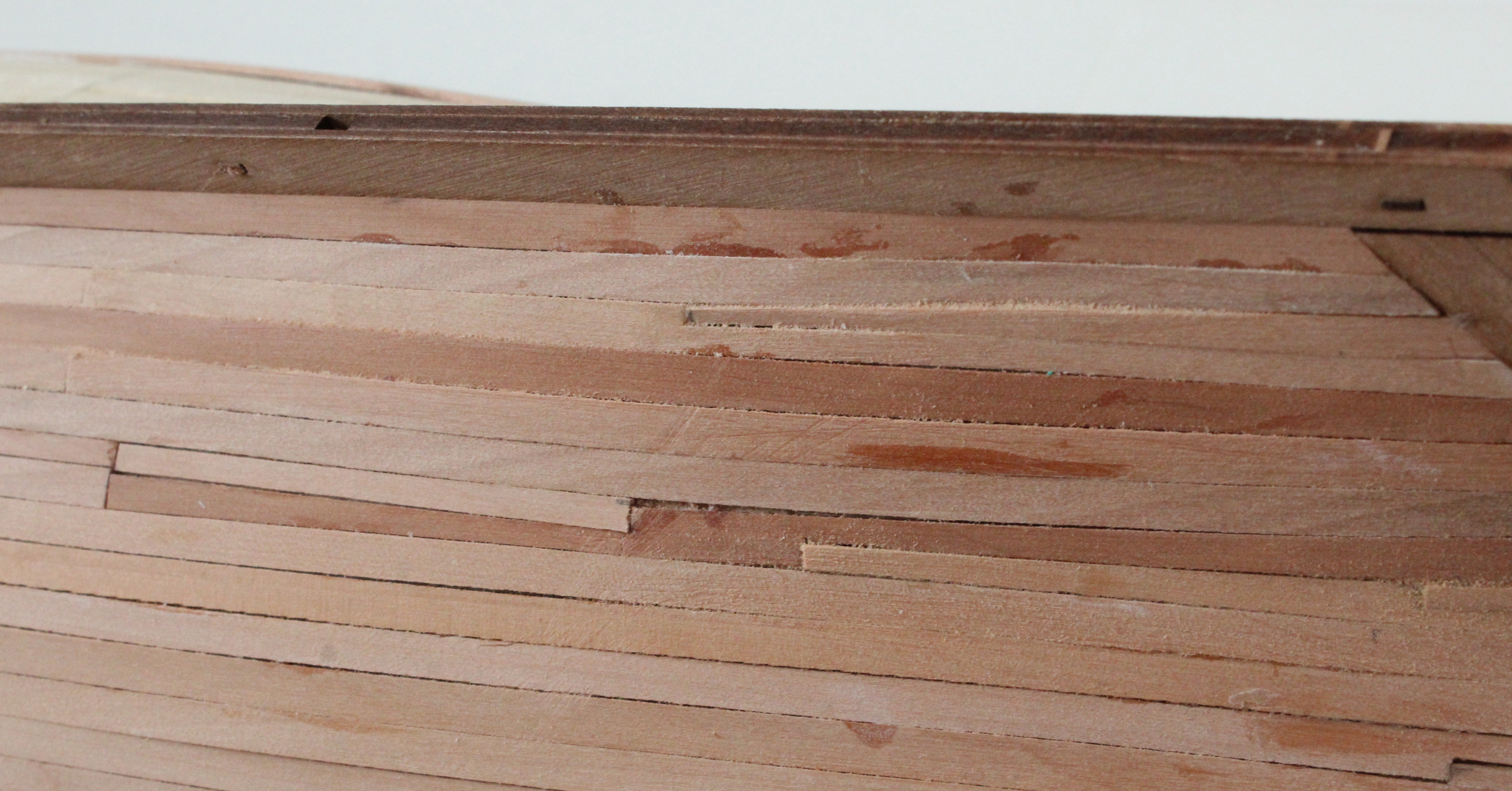
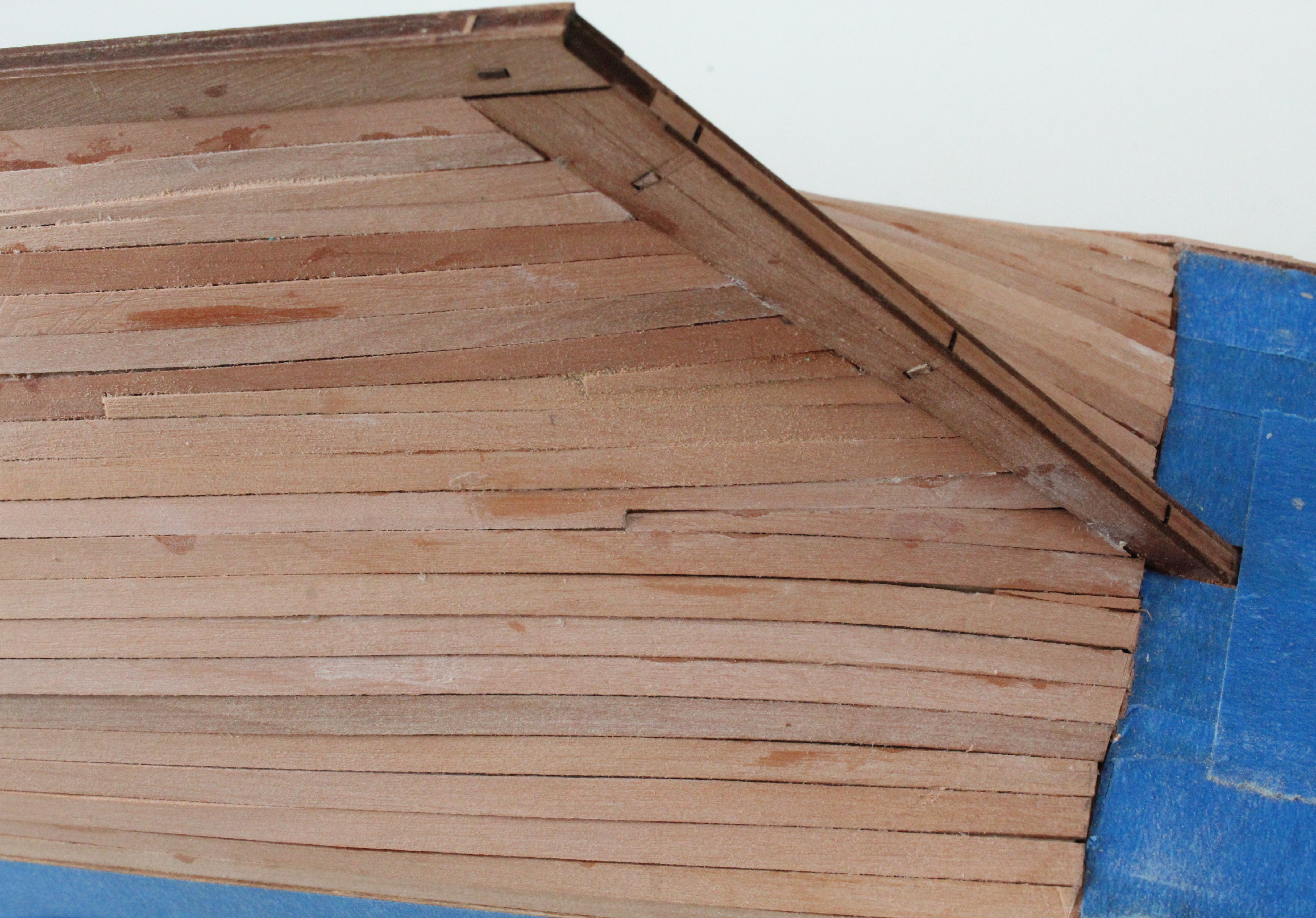
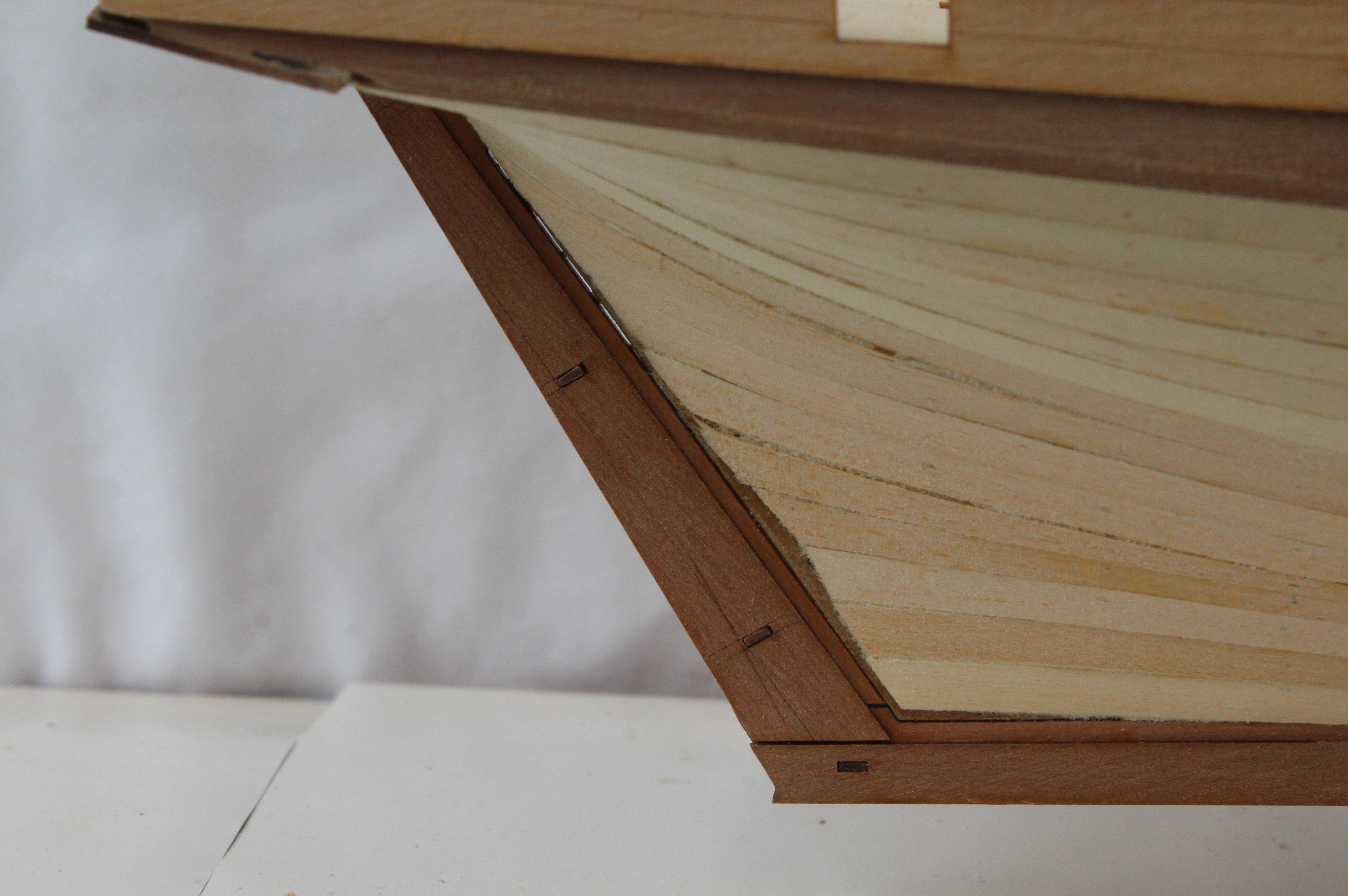
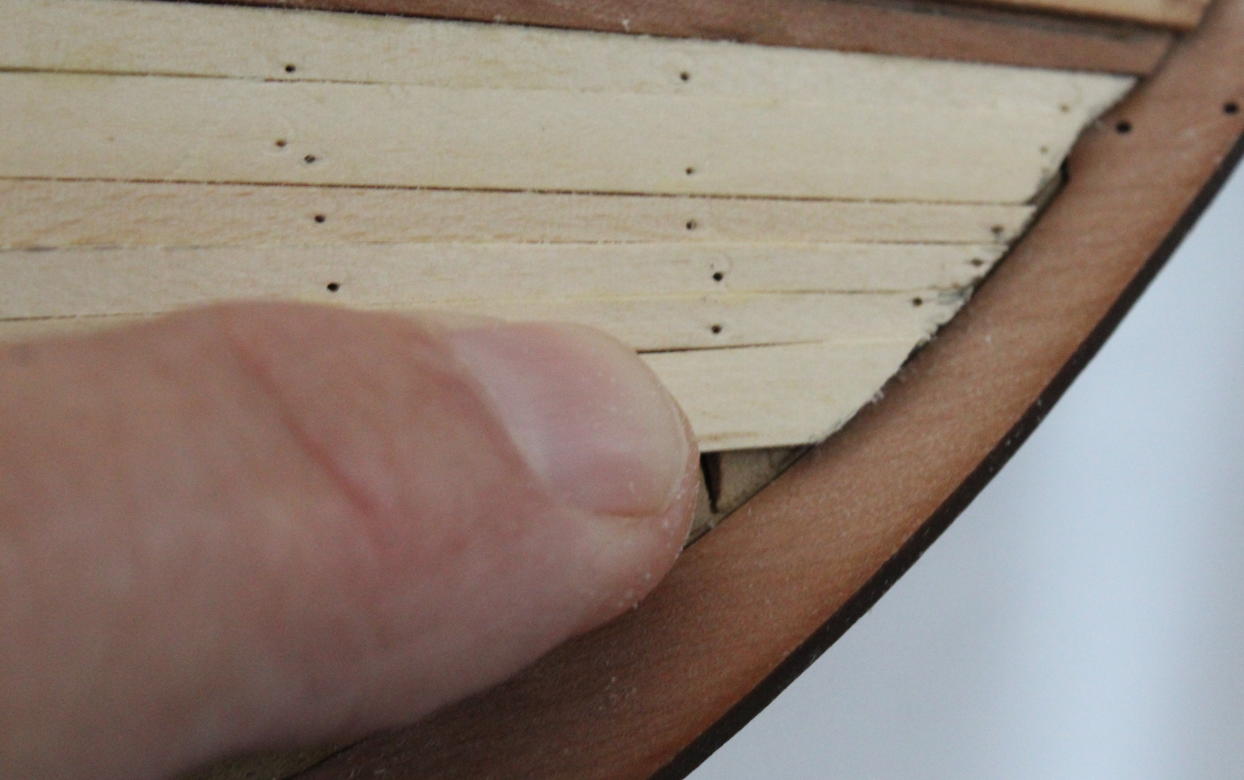
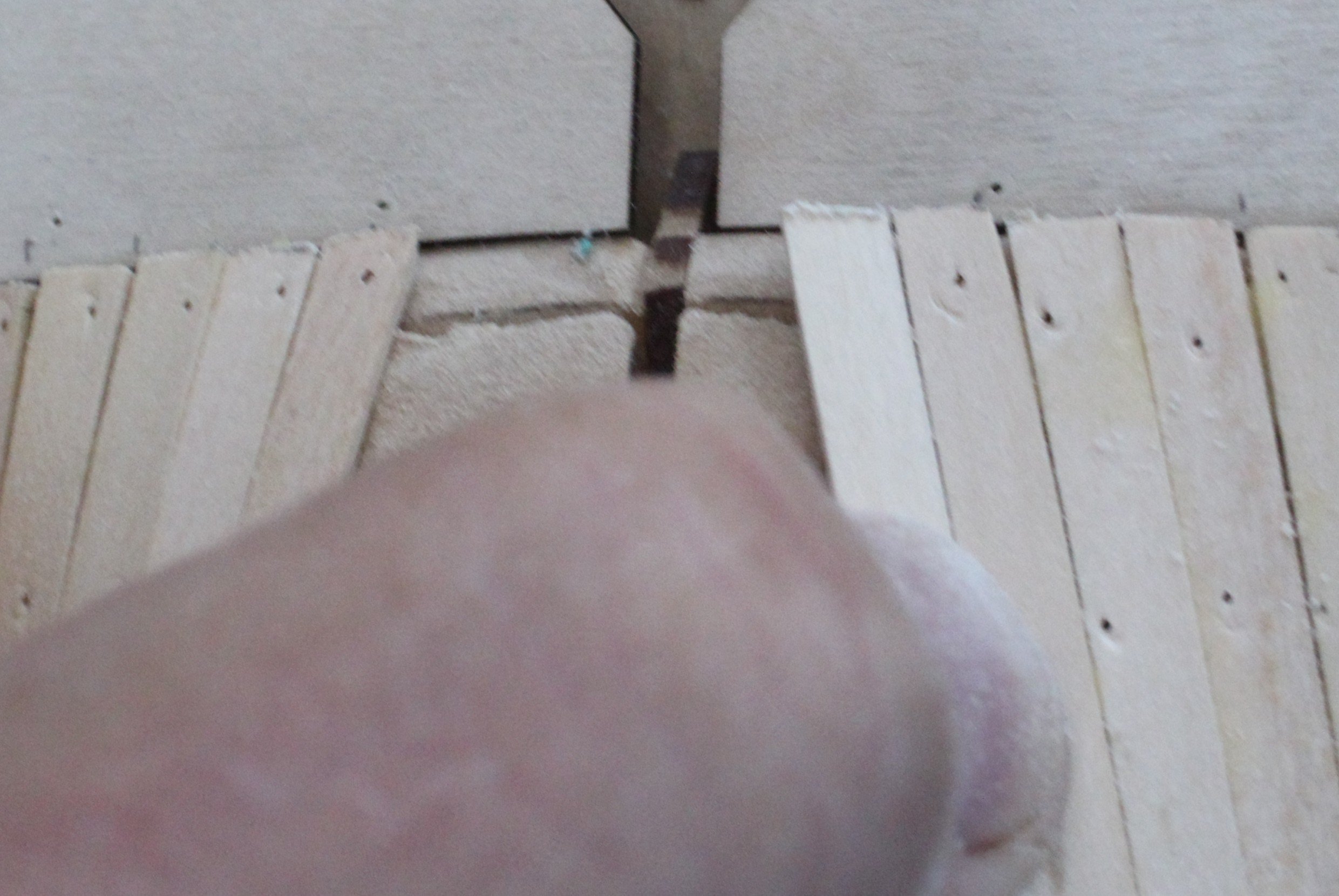
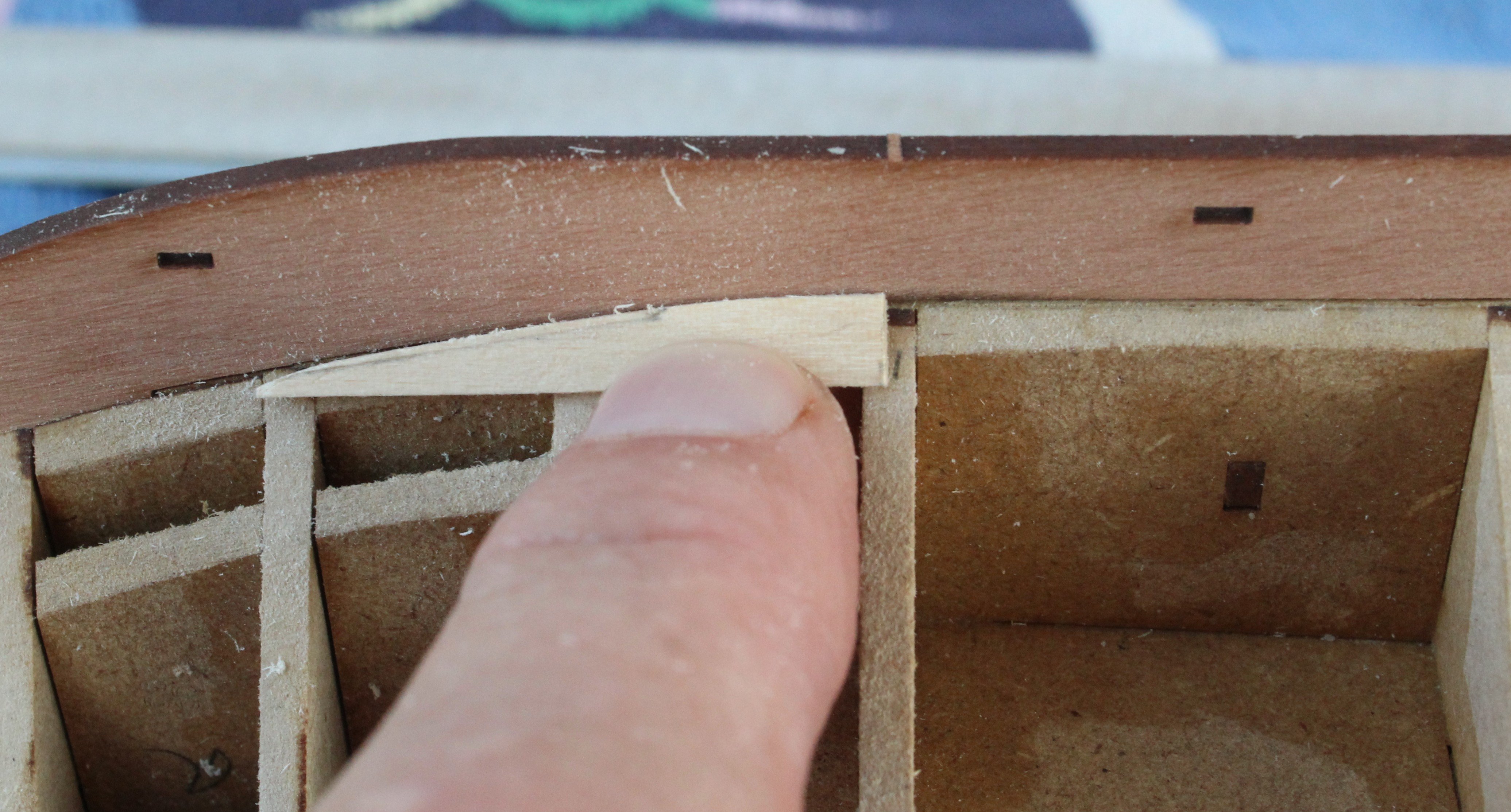
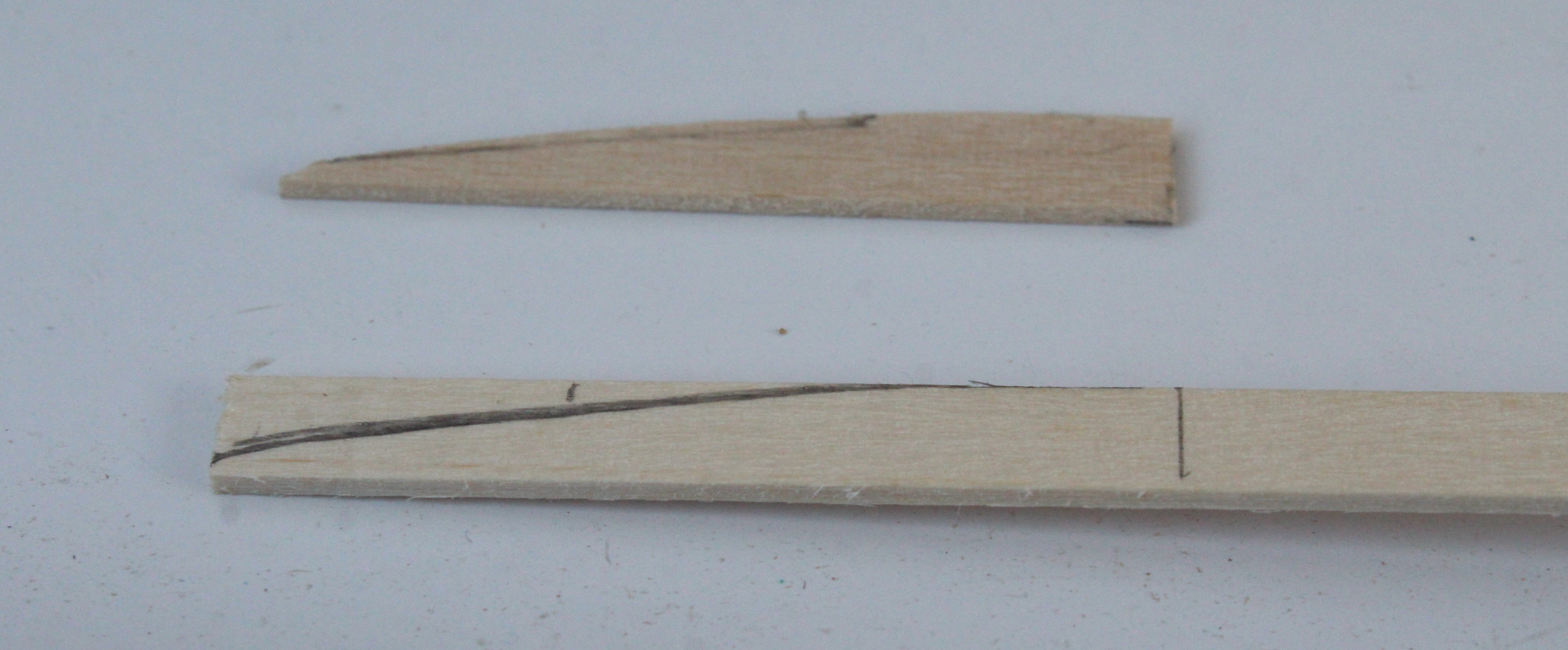
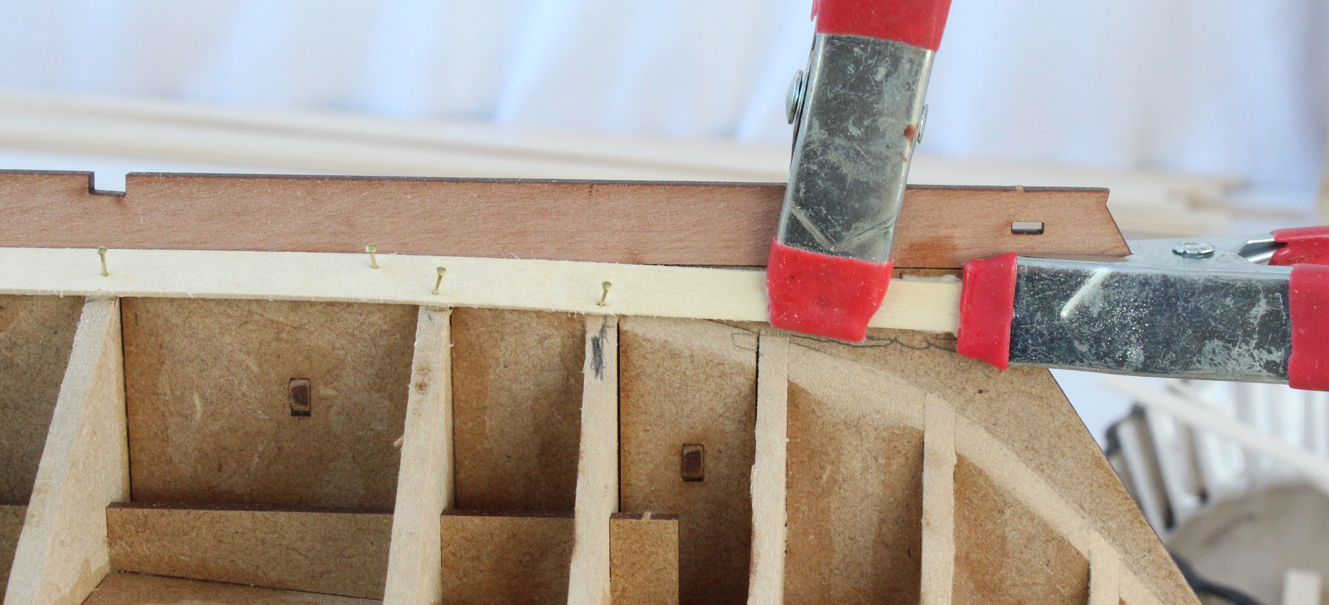
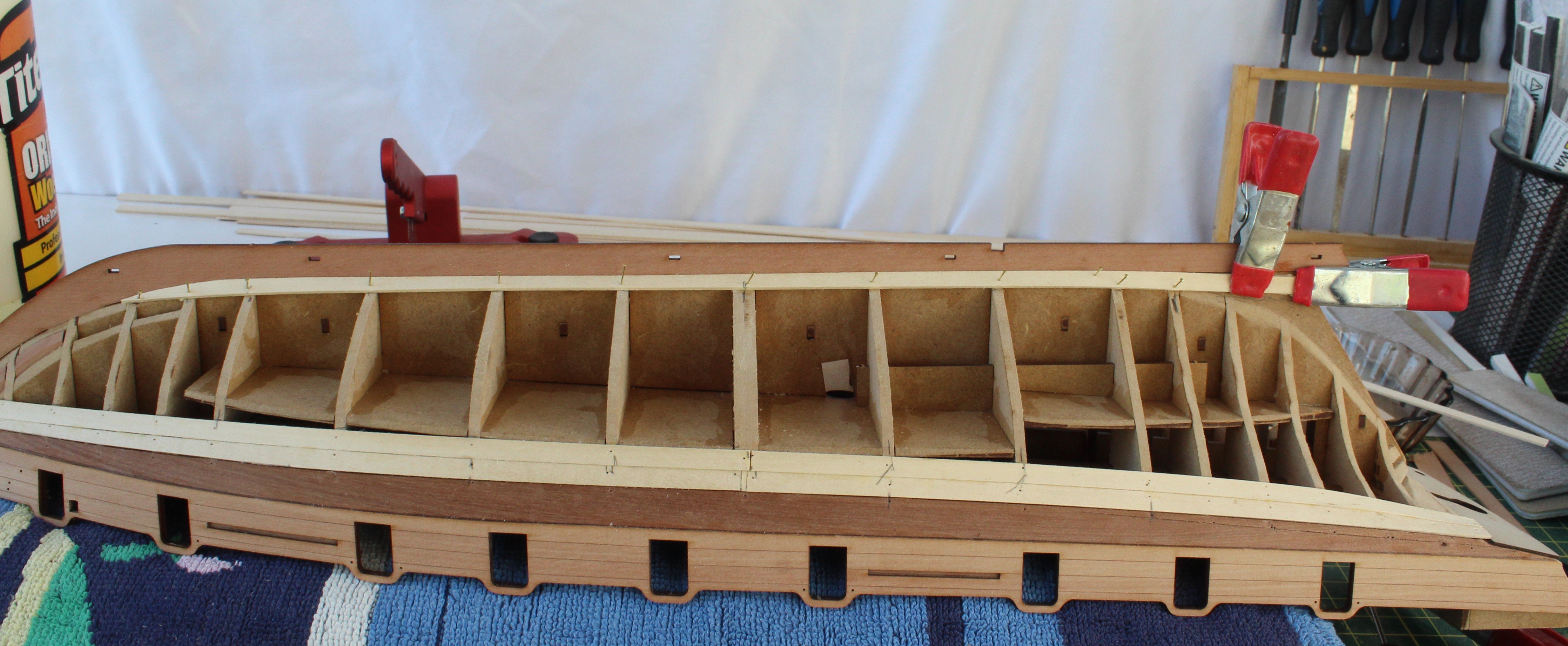
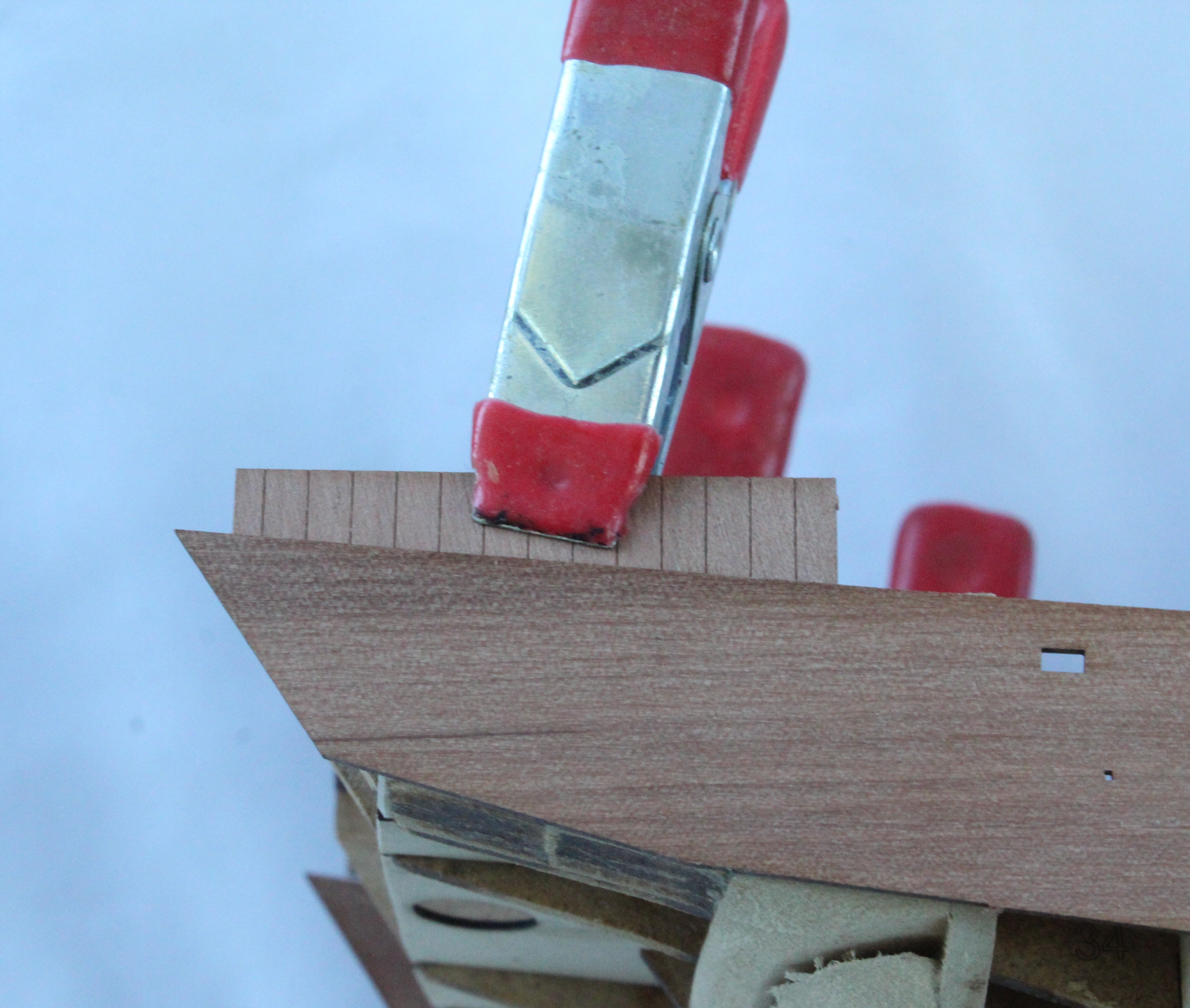
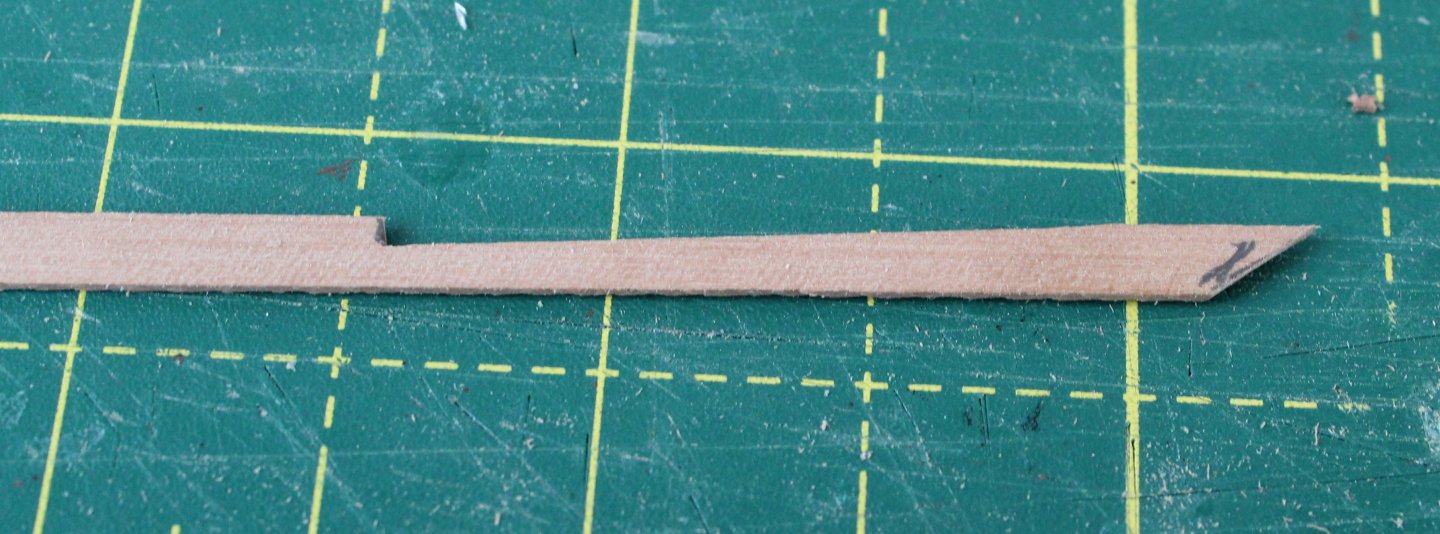
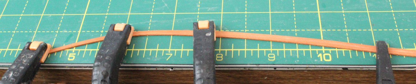
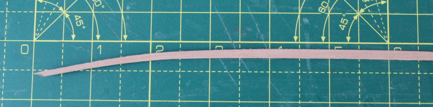
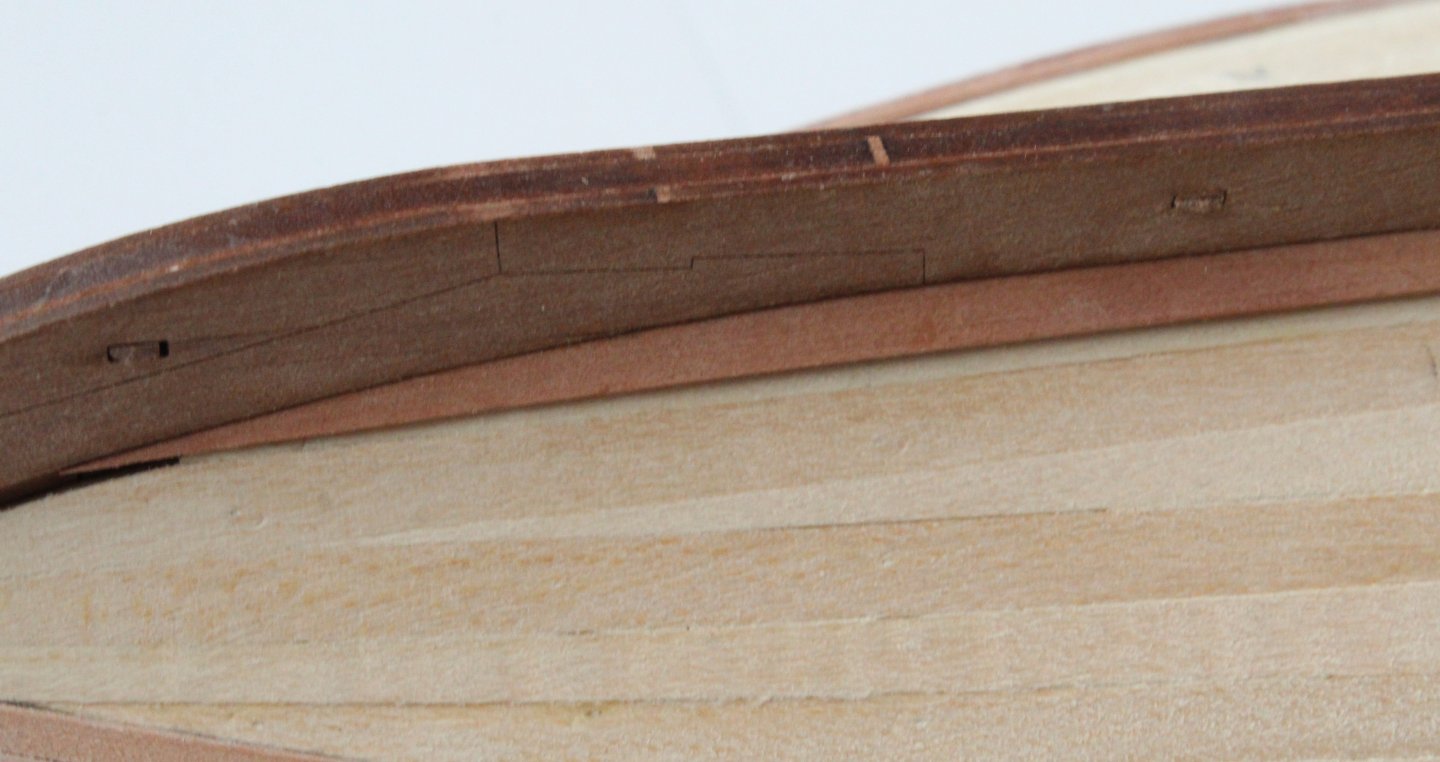
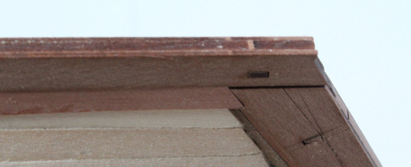
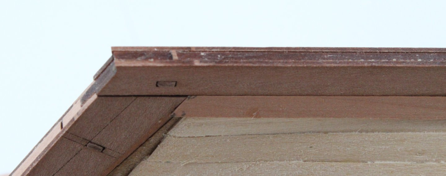
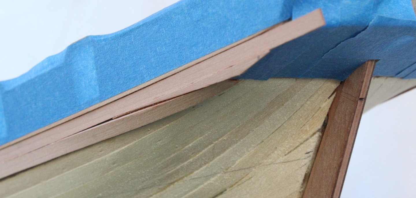
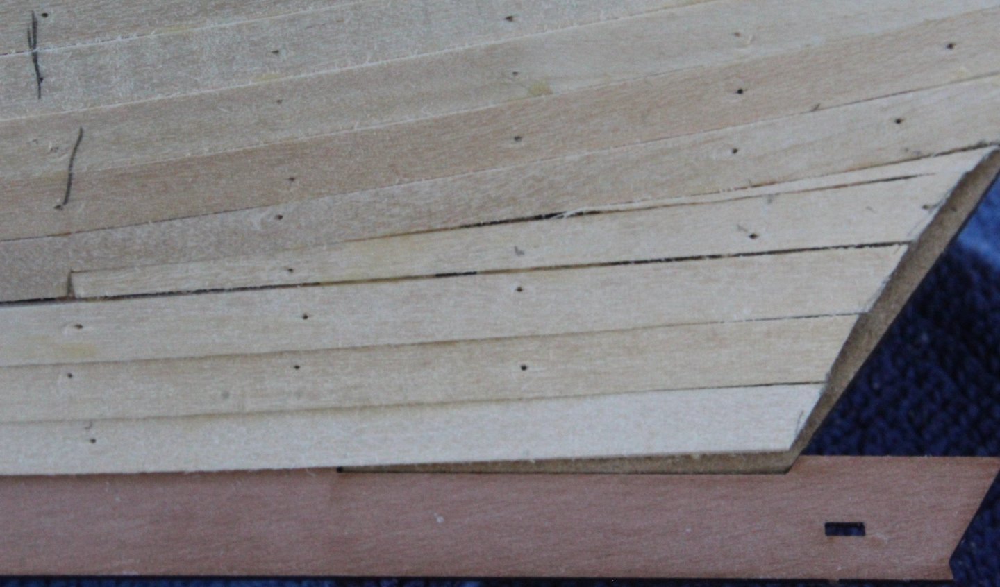
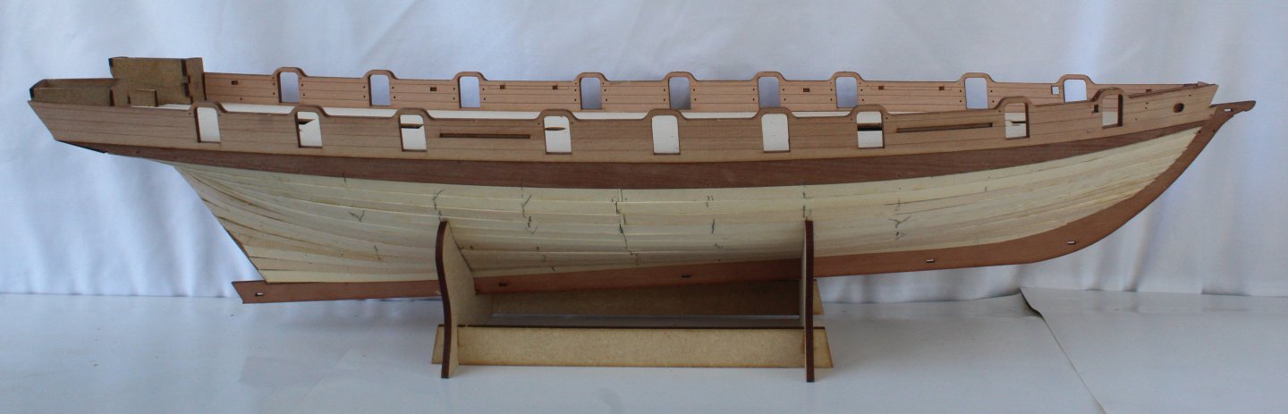
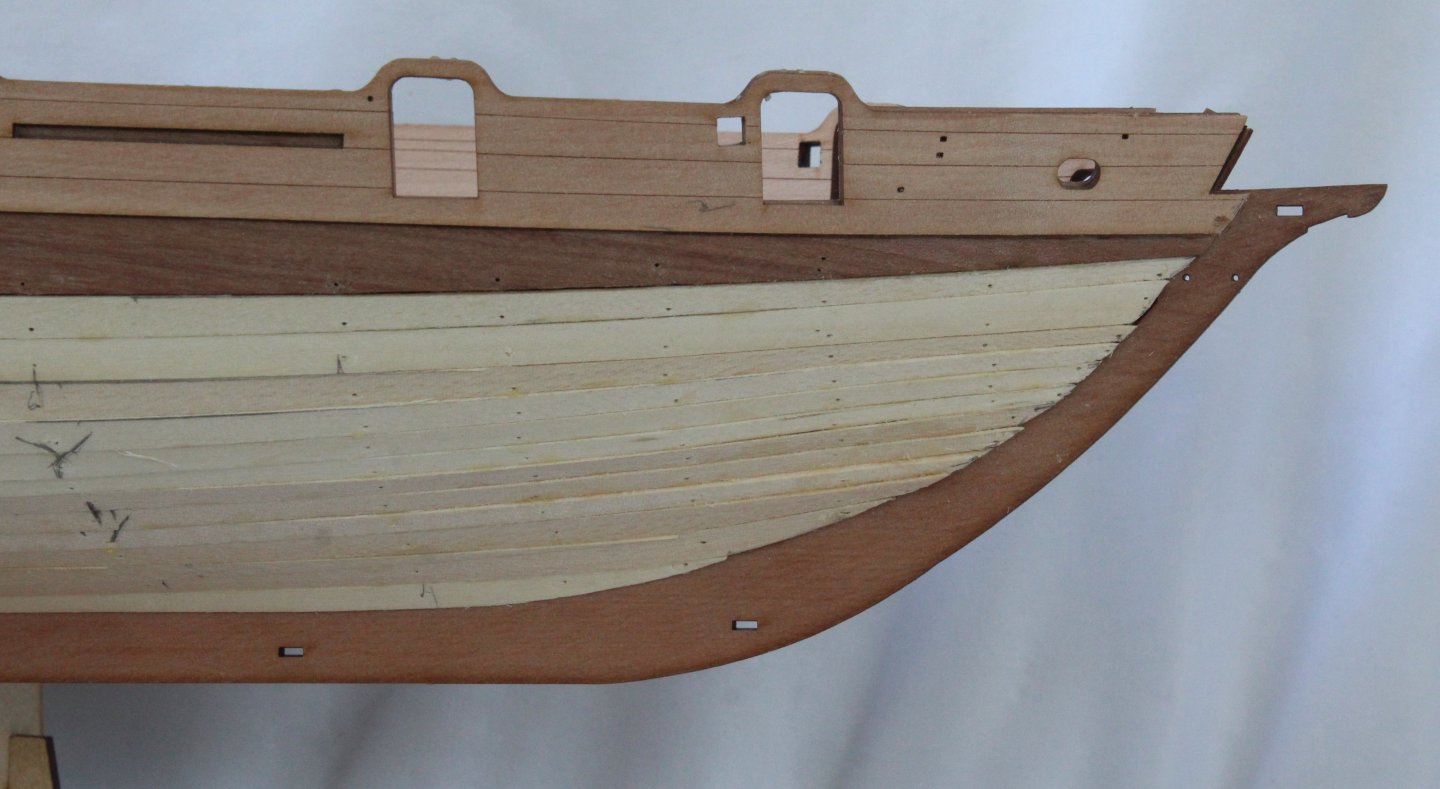
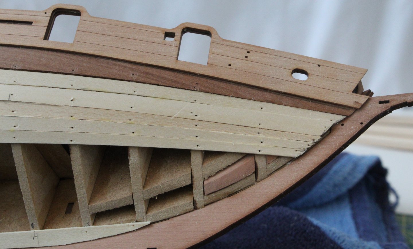
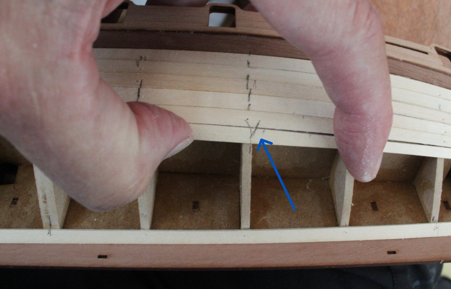
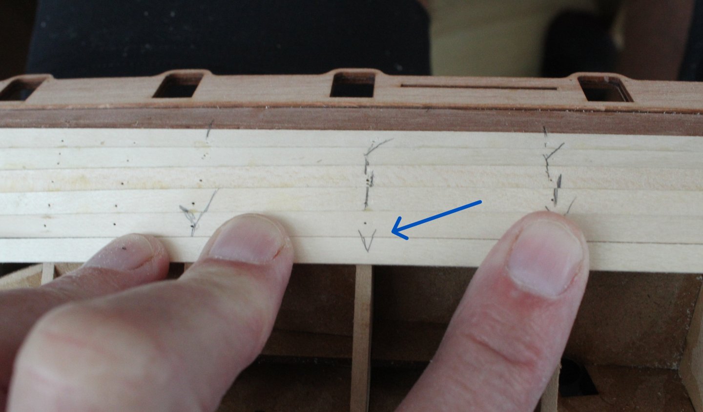
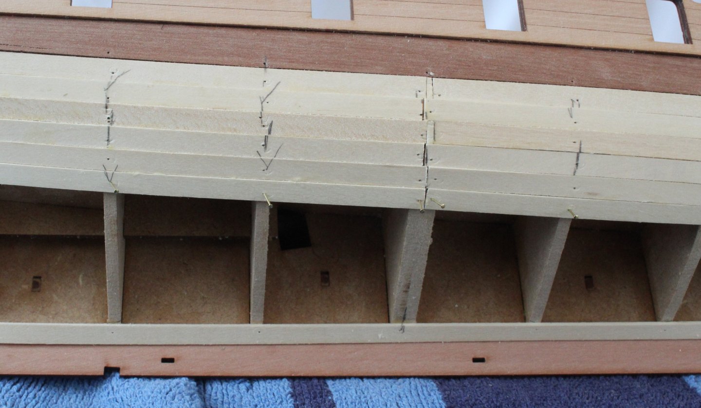
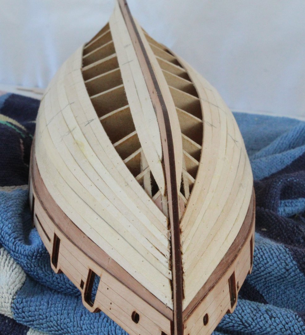
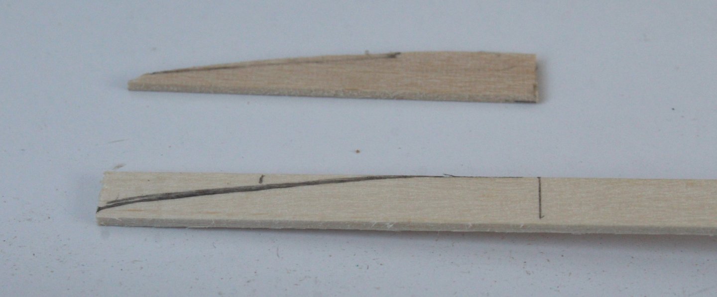
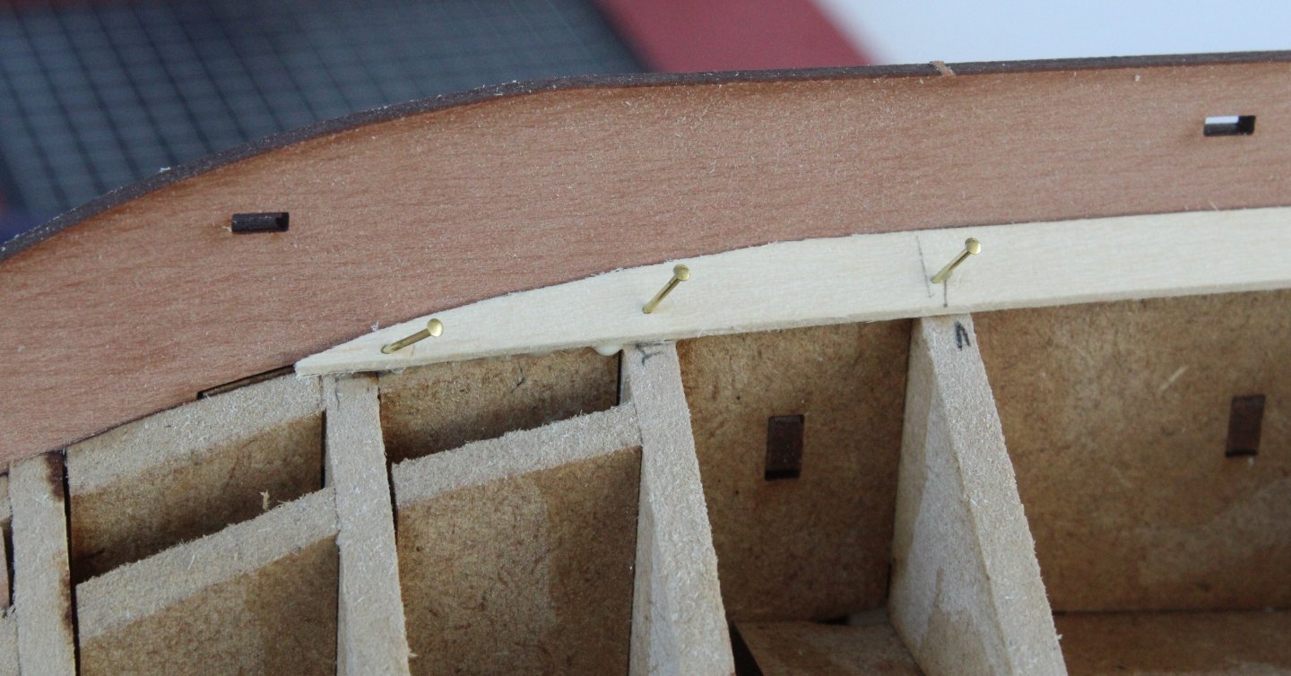
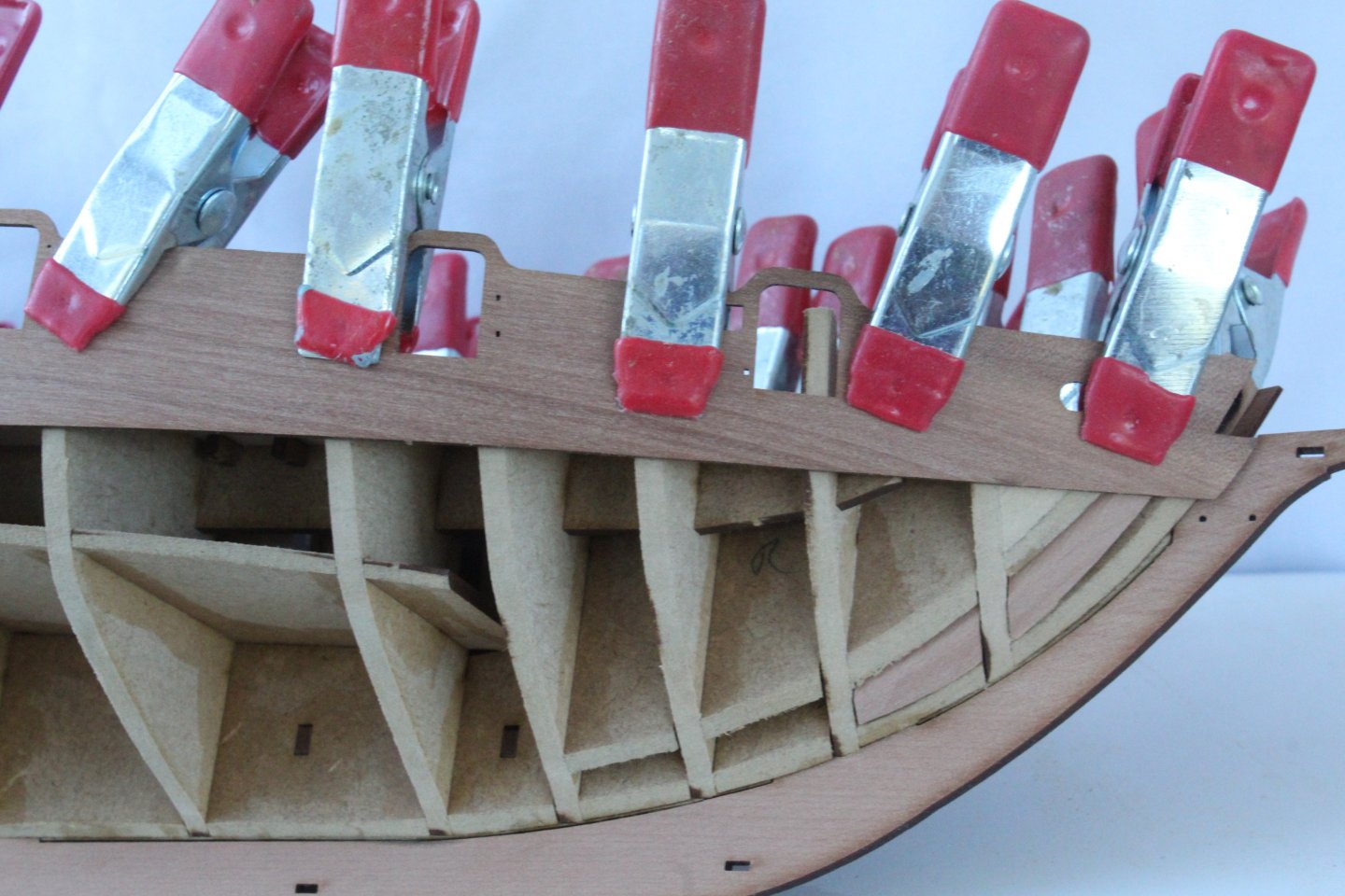
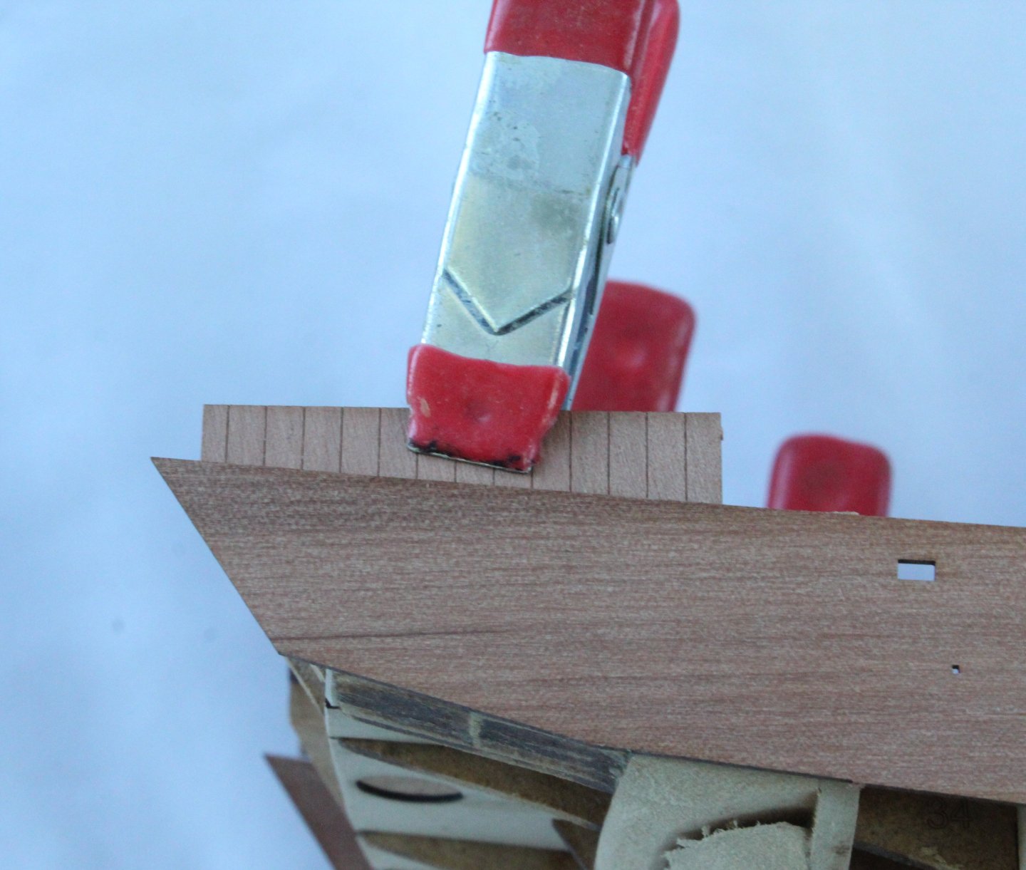
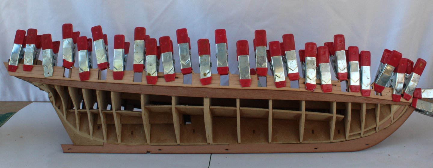
As I work towards completing the left hand side second planking I thought I would share how I go about adding a steeler. With the plank in place I make a mark where it starts to drift away from the next plank. This is shown in the photo below. I also aim to have a full plank width space at the stern post and you will note I have also made a pencil mark on the hull near the stern post. I then cut away the excess material from the plank. The objective is to have about a taper that goes from about half a planks width to a full planks with. I think the next photo will help to clarify that description. Next I make the steeler and check its fit before progressing further. Once I am happy with the fit I will then glue the steeler in place. Doing this ensures I have the right space set at the stern post for the plank when fitted. The plank is then glued in place and all looks good. You will note I did not do such a good job this time around as I found it necessary to add a small filler piece. I use a very simple method when laterally bending the bow planks. I dip the plank in some water and then clamp it to my workbench. A hairdryer is then used to blow hot air on the plank to remove the water and to retain the curve. Once the water has been removed by the hairdryer I am left with a nicely curved plank. The curve, if necessary. can be adjusted but with experience I have found I am now usually able to judge the required bend first time around. The left hand side second planking is now complete. The completed hull is now ready to be sanded (and filled) prior to painting and adding the copper plating.


-
Hello Craig https://fundraise.cancerresearchuk.org/page/glenns-giving-page-185 Thanks Glenn
-
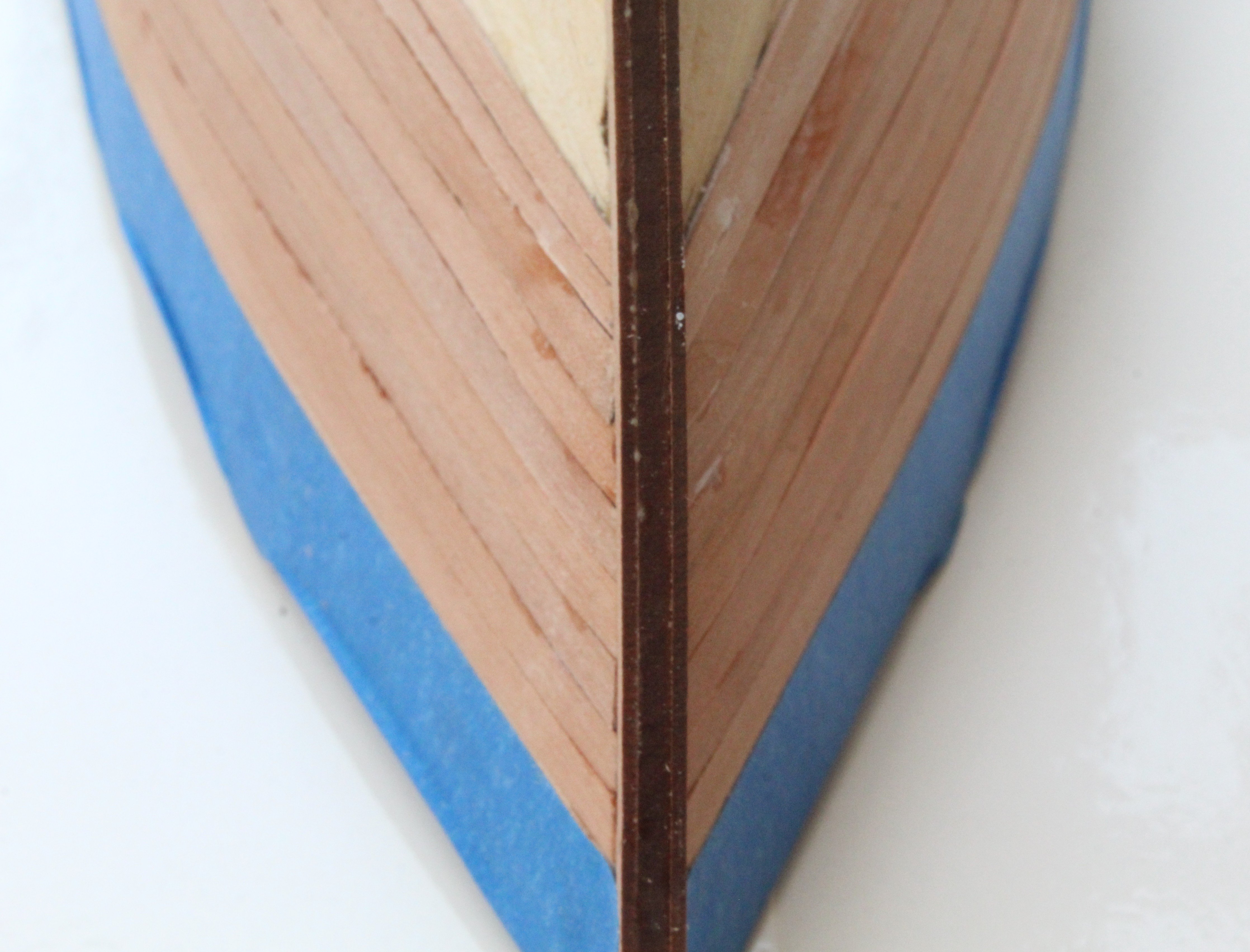
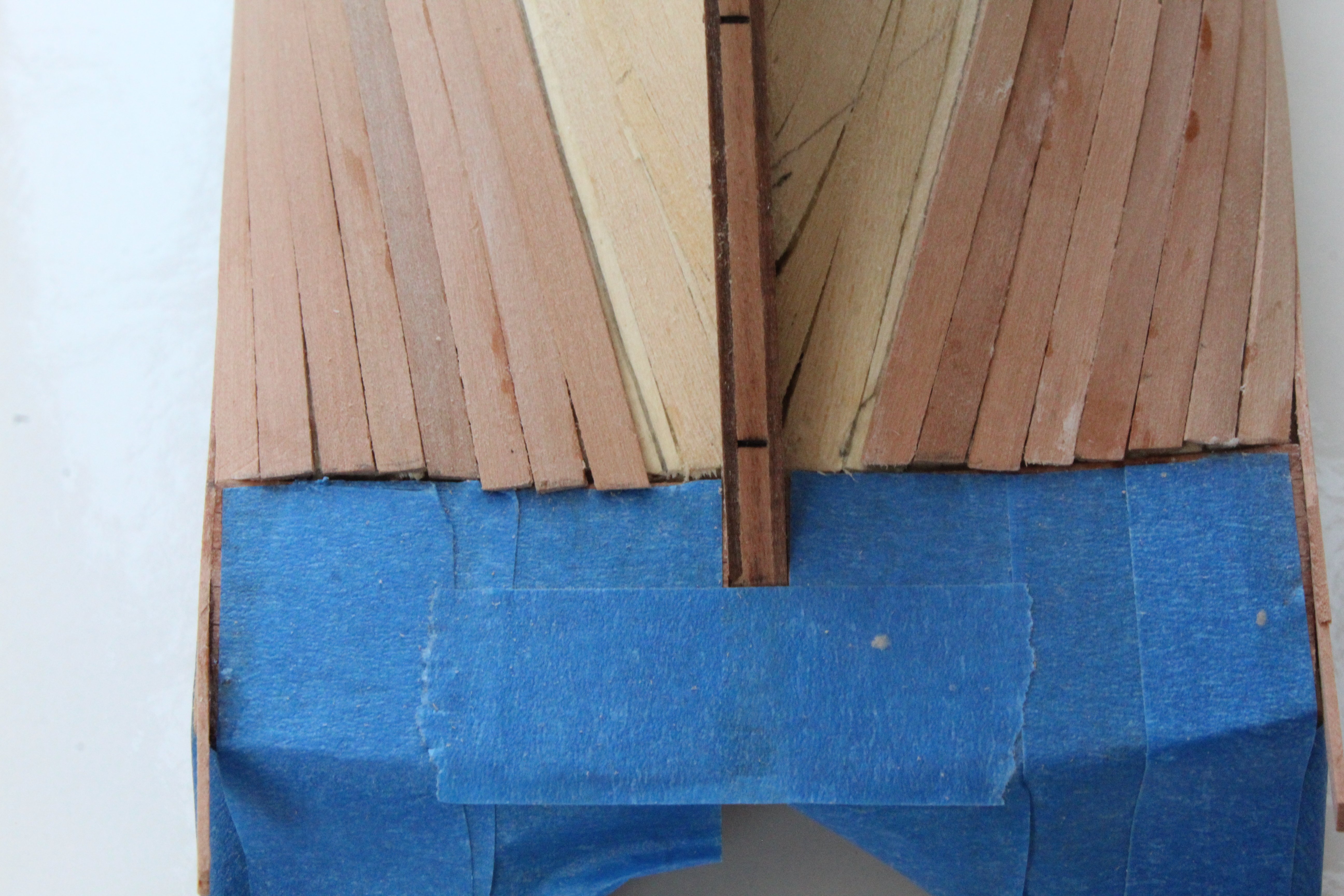
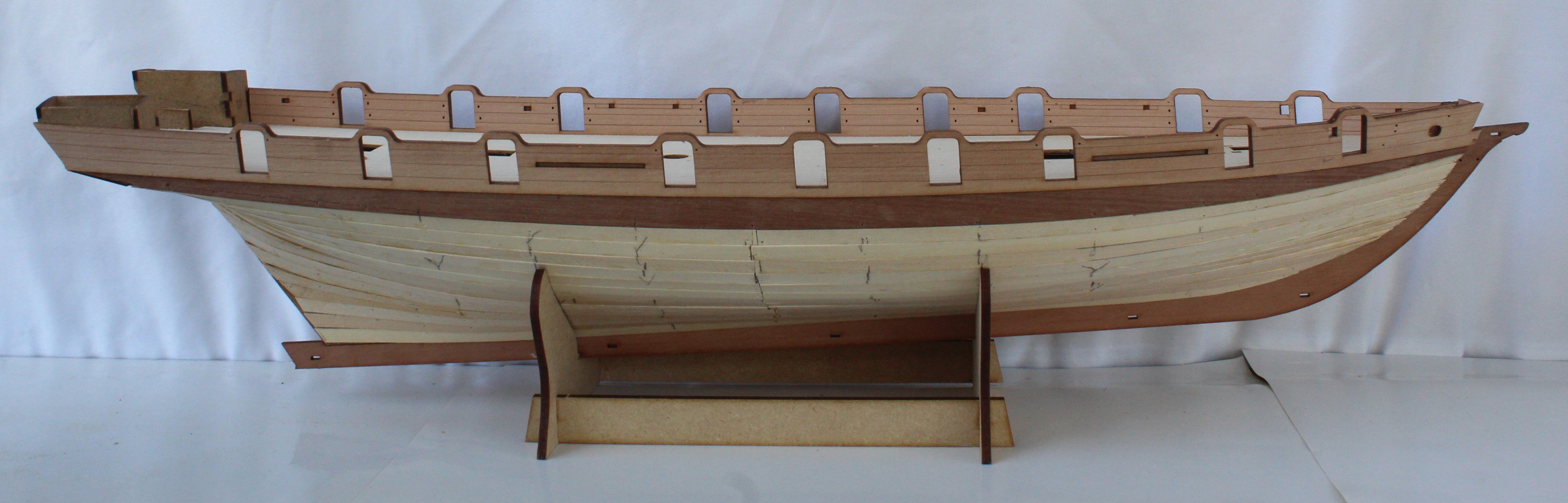
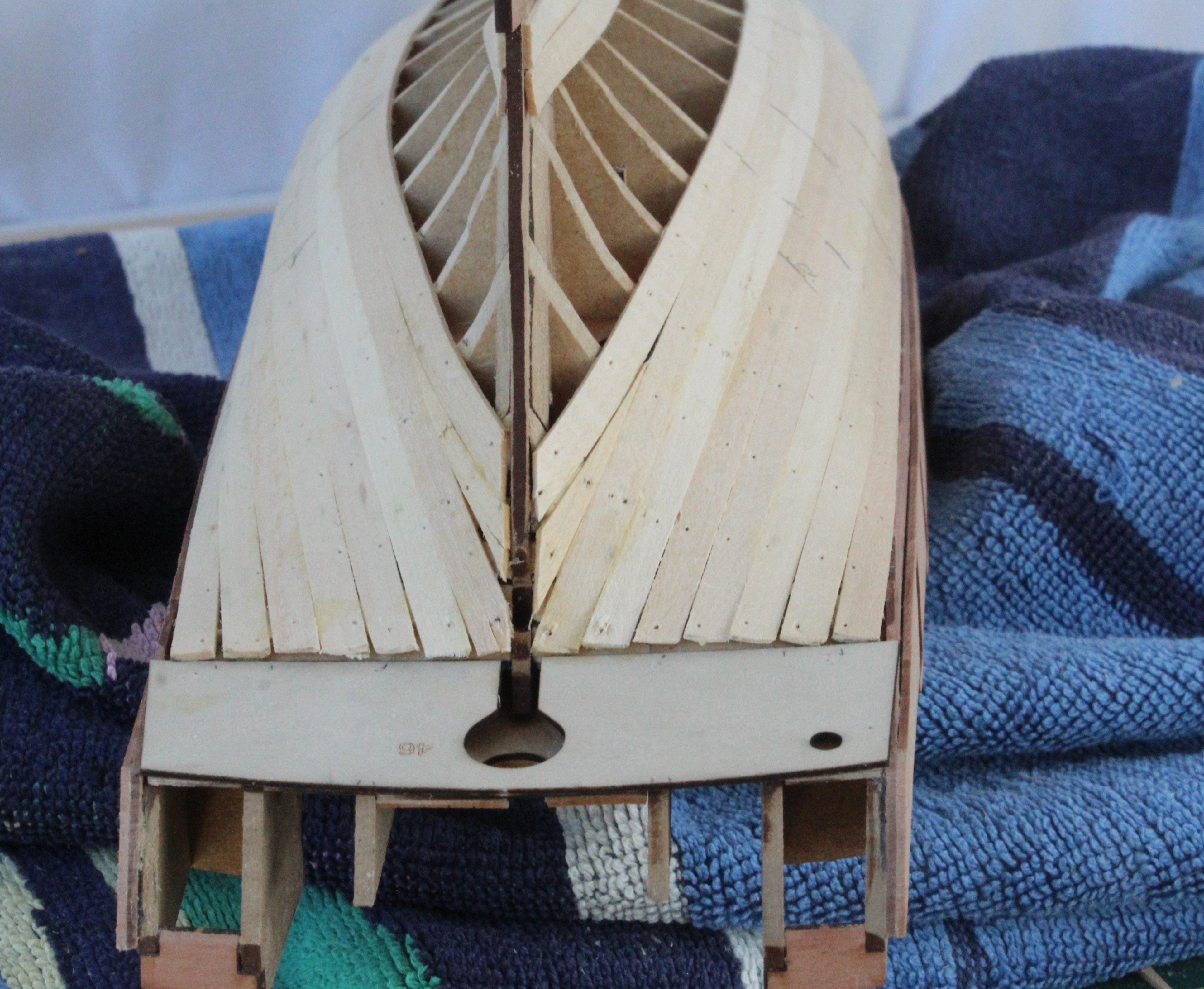
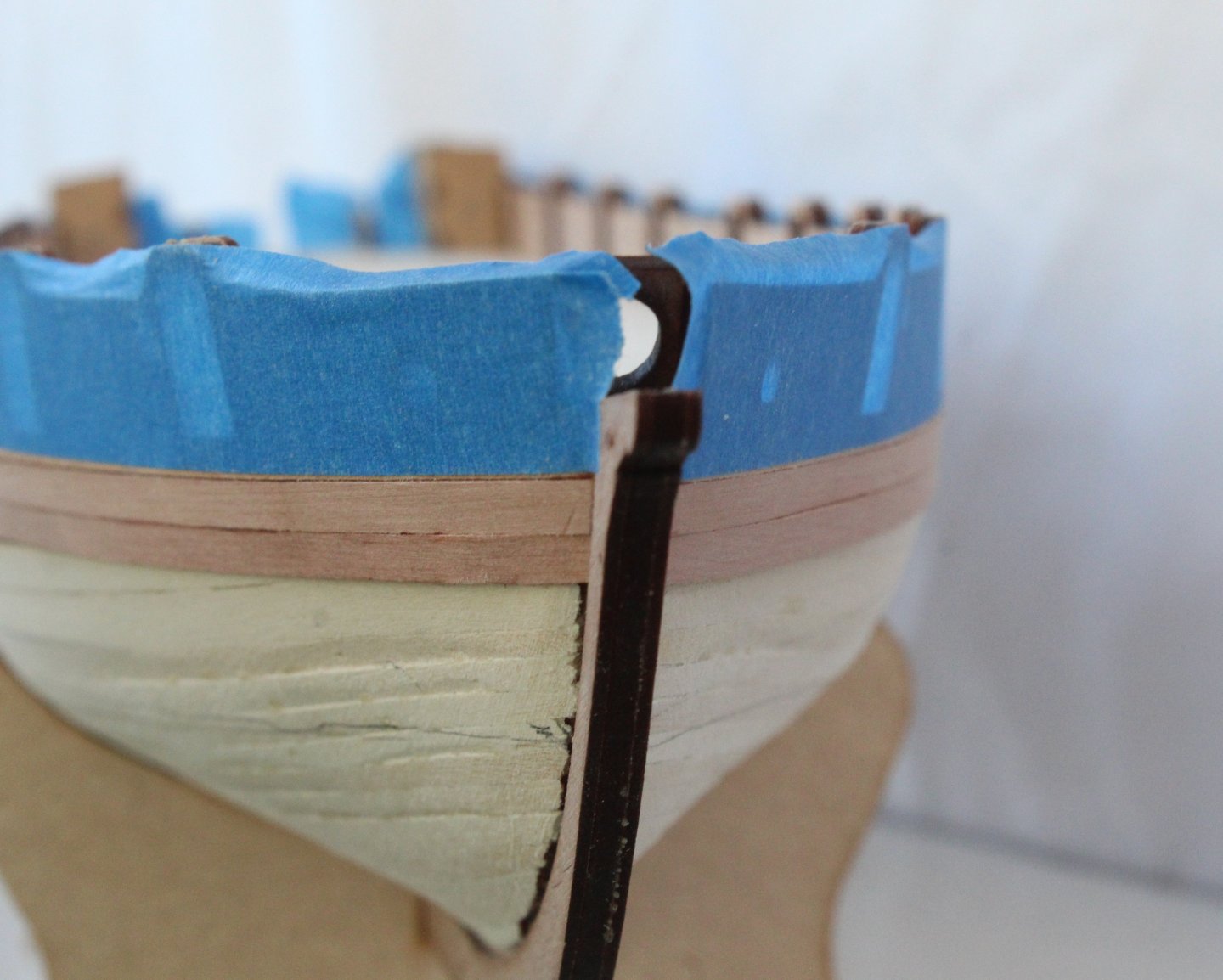
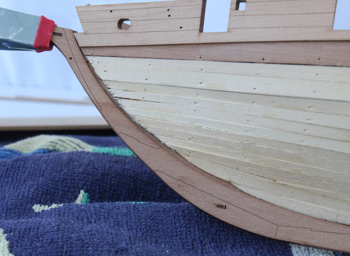
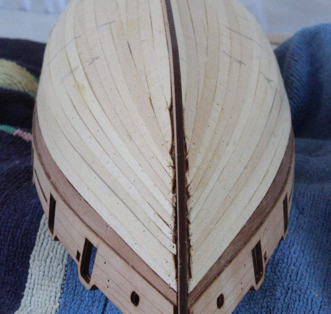
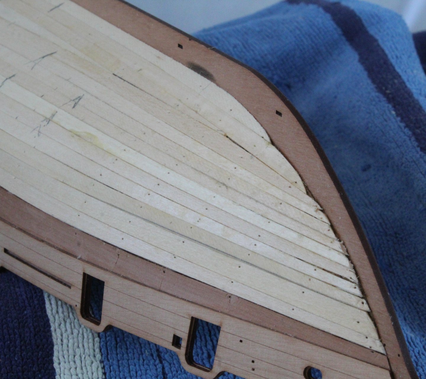
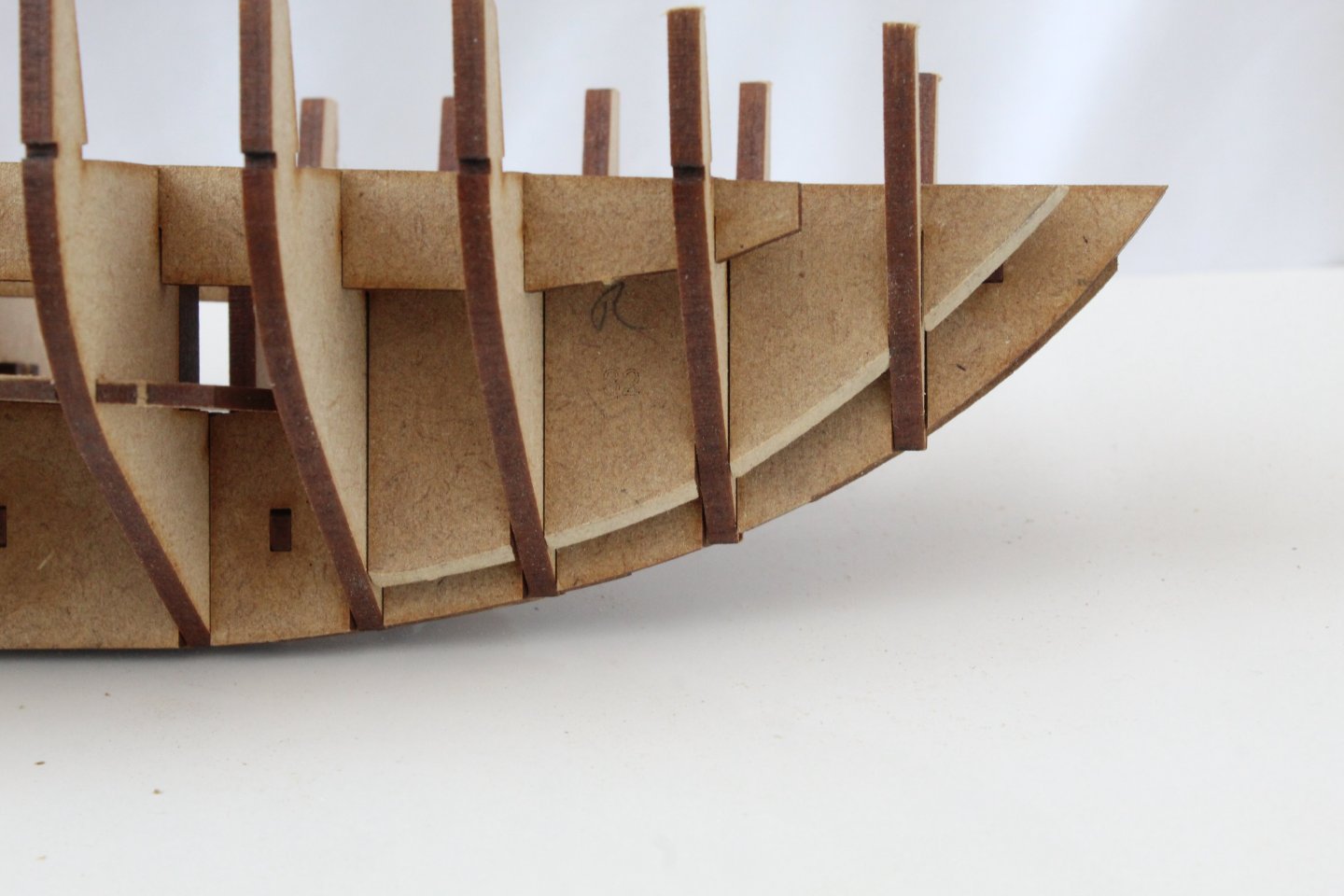
Just a quick update before we travel to yet another hospital appointment. I have completed the second planking on the right hand side. For the most part I am happy with the end result. I did have some acetone on hand as the planks were glued in place to wipe away any excess. As can be seen in the next photo I did not follow the correct method for planking around the bow but as the hull will be painted and copper plated it does not really matter for this build. I did find it necessary to laterally bend the tapered planks to get a good fit. I did add some steelers when planking the stern. The left hand side is nearly complete and hopefully I will be able to complete this the next time I am in the shipyard. I did manage to release and reset the plank mentioned previously.


-
Thank you for all the messages of support, they are all greatly appreciated.
-
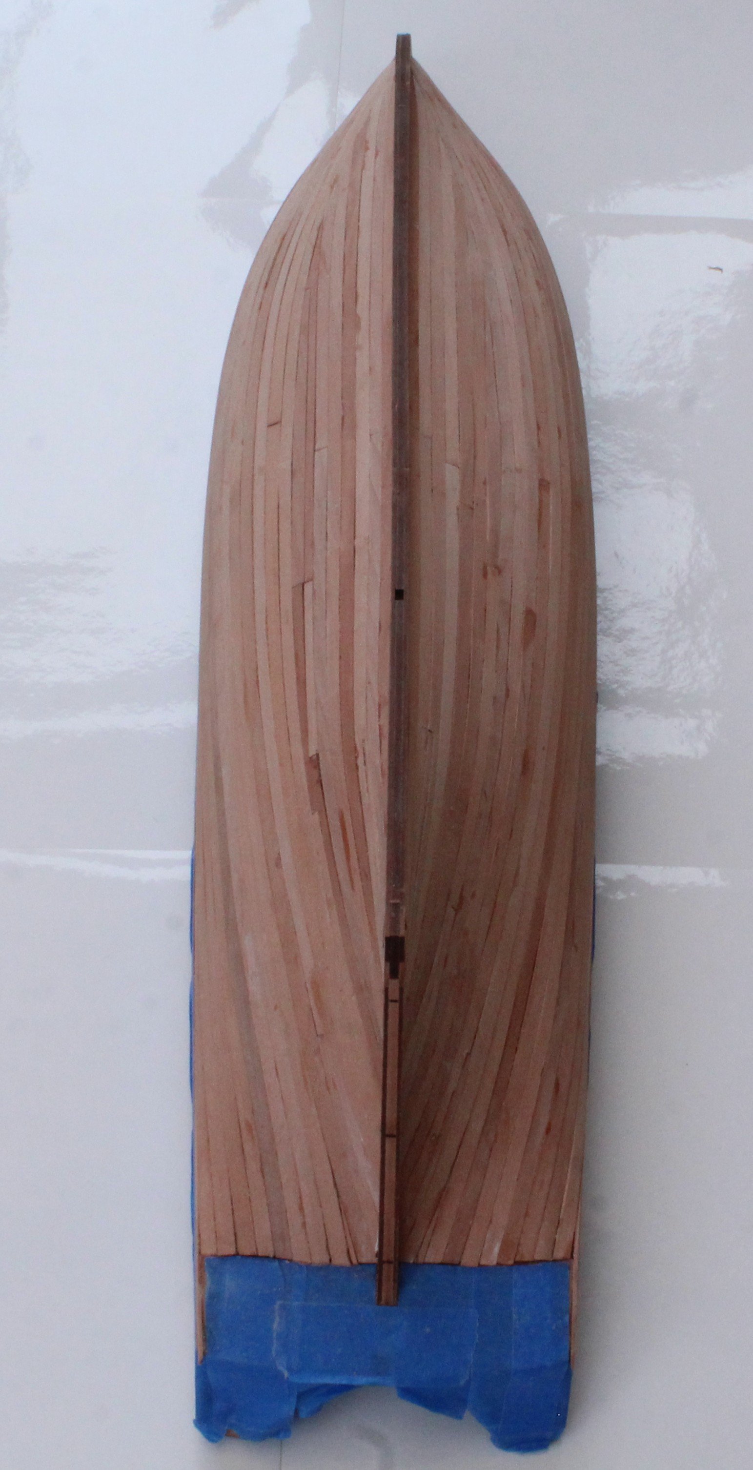
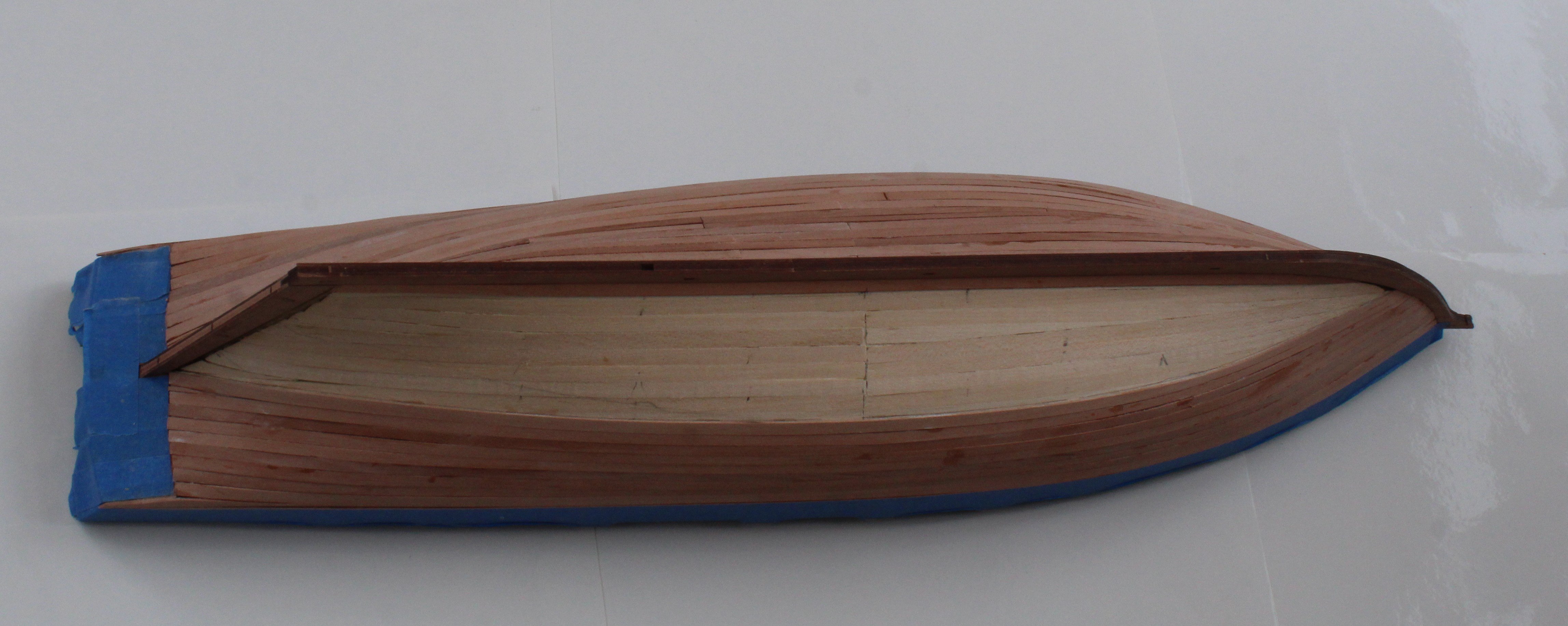
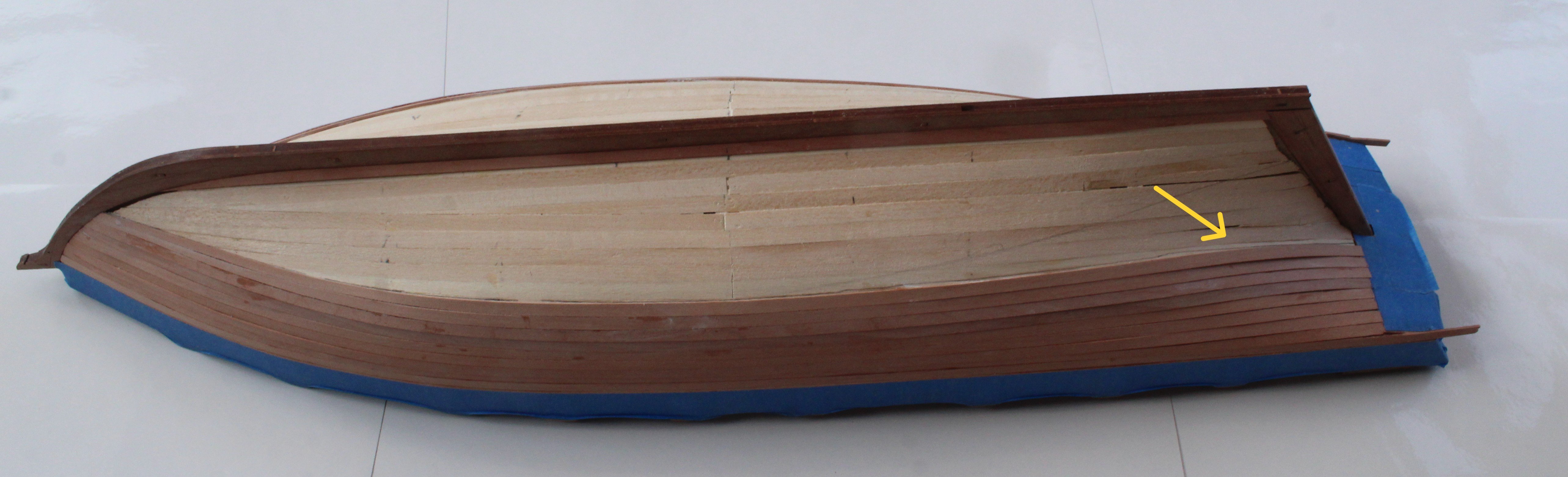
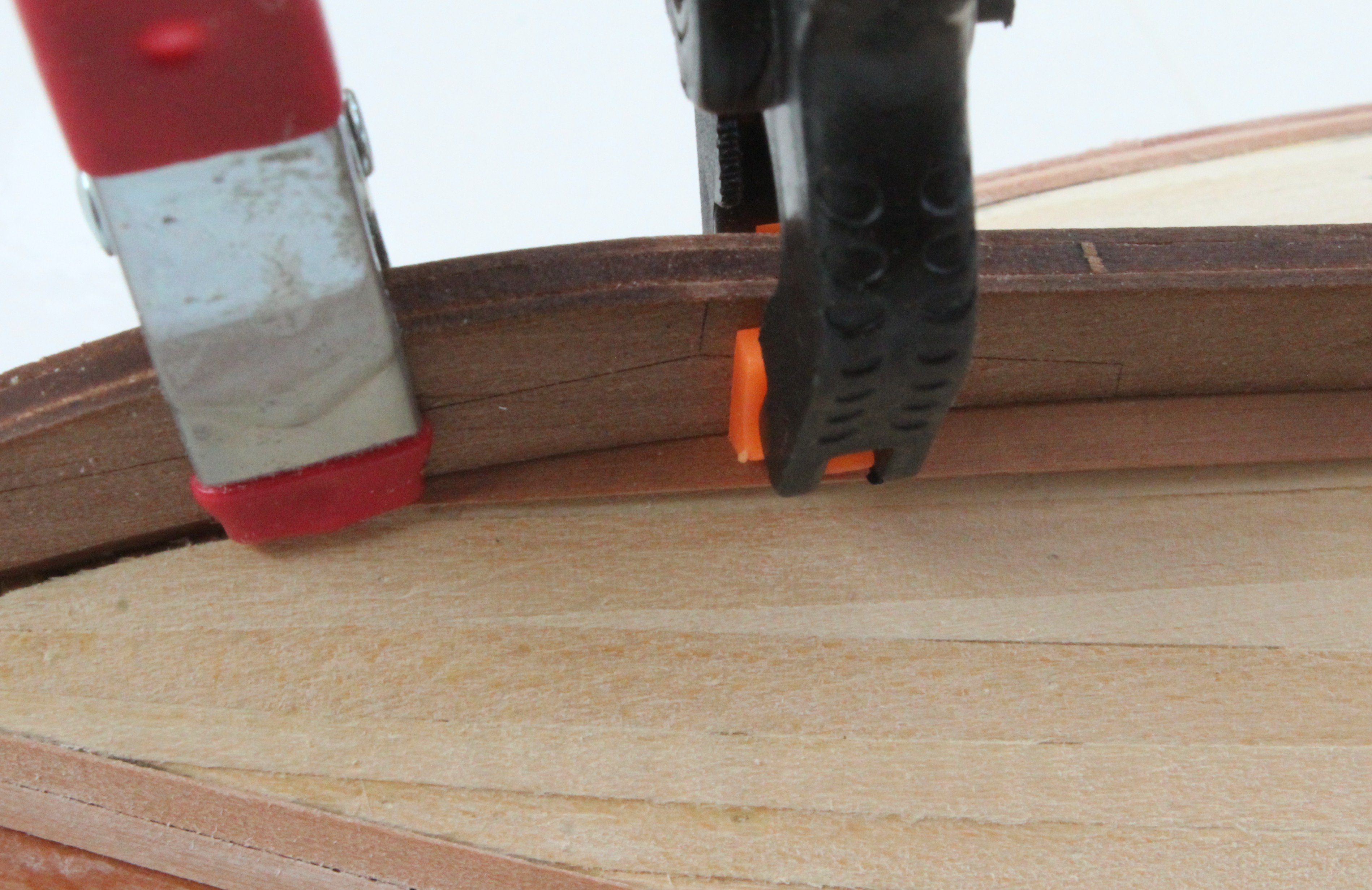
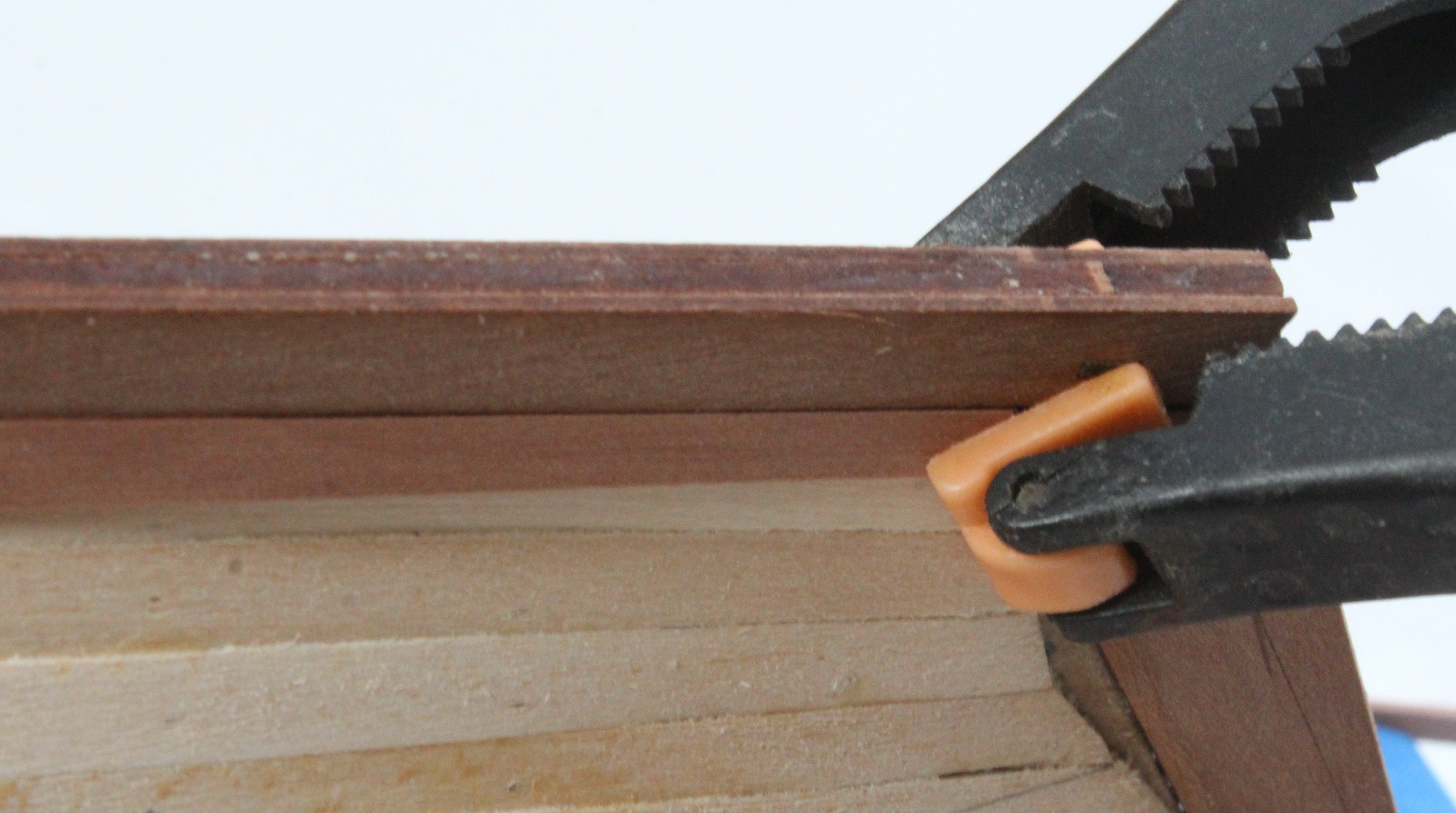
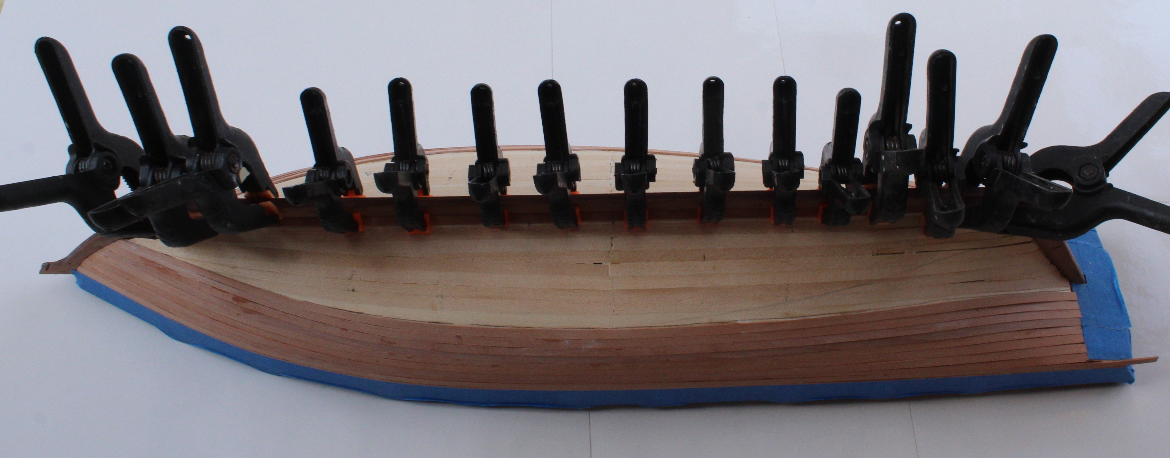
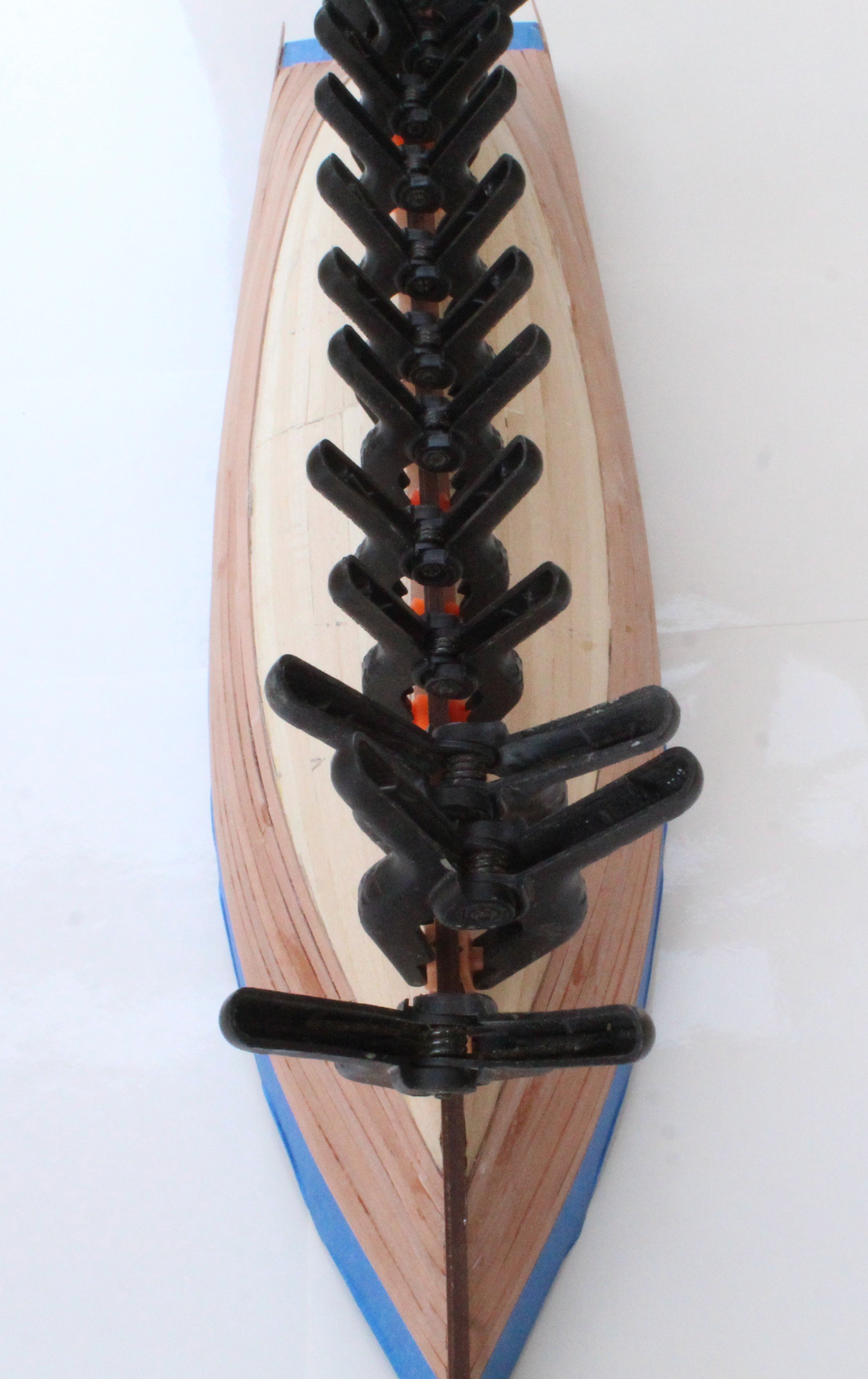
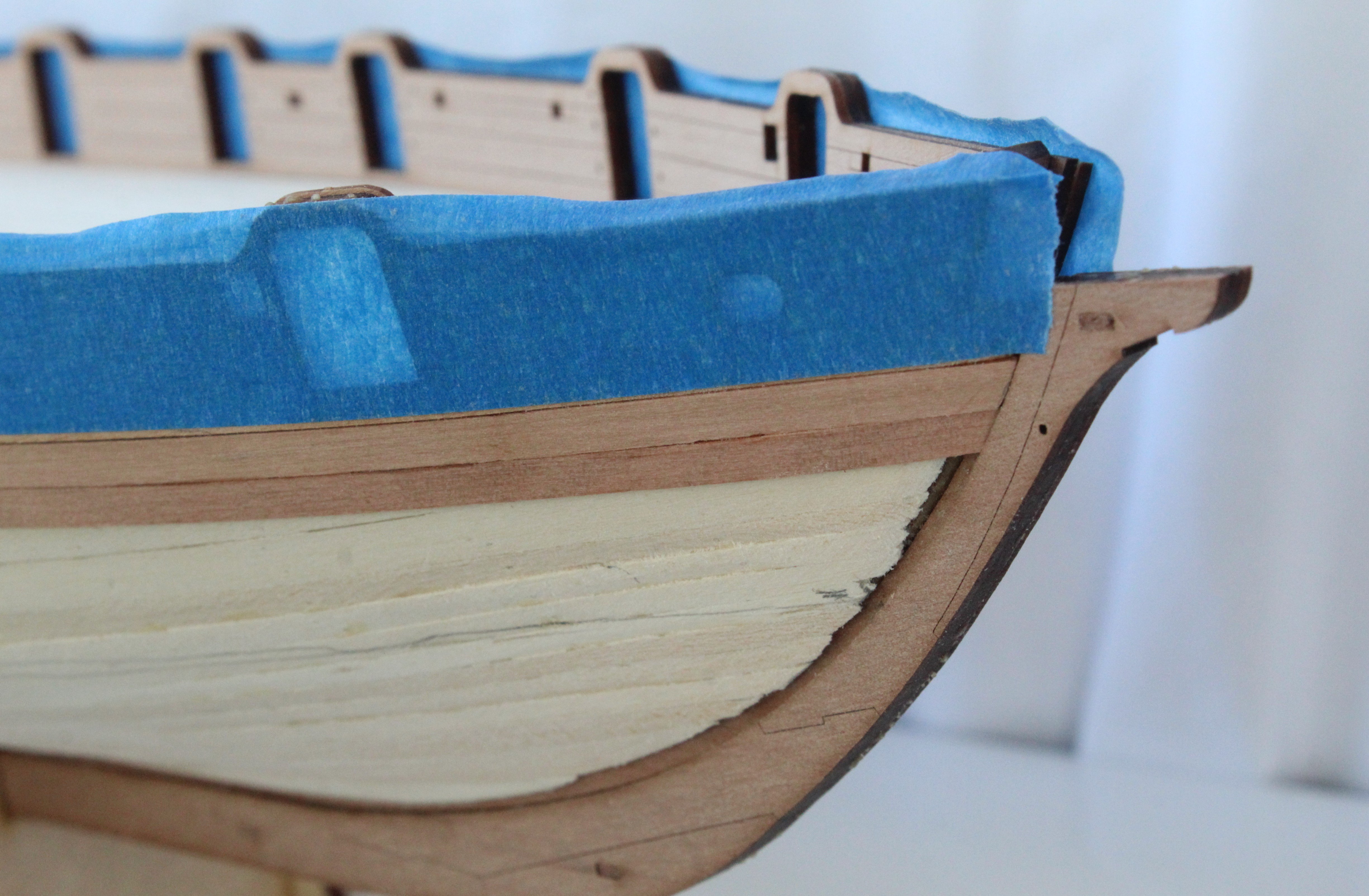
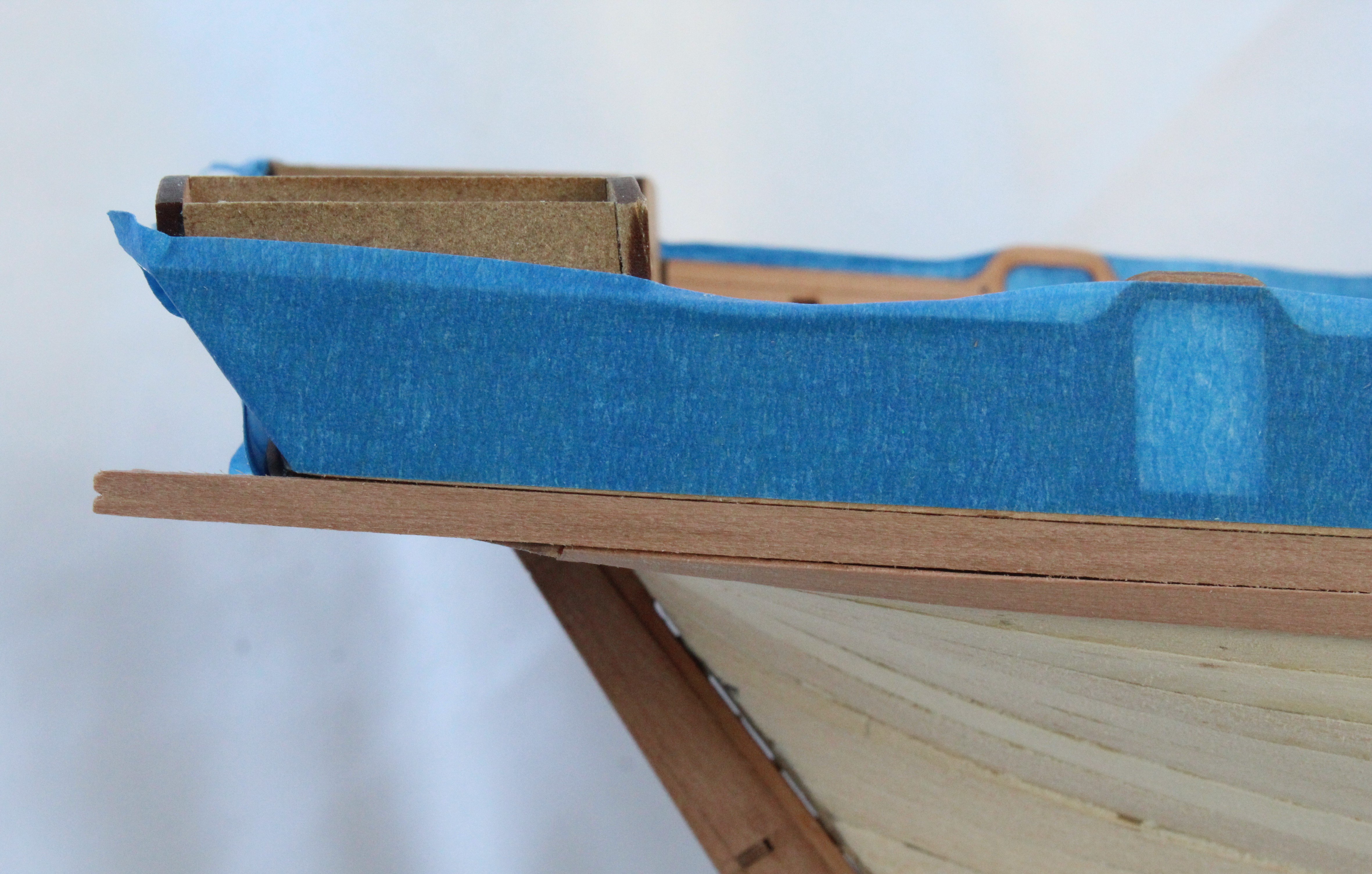
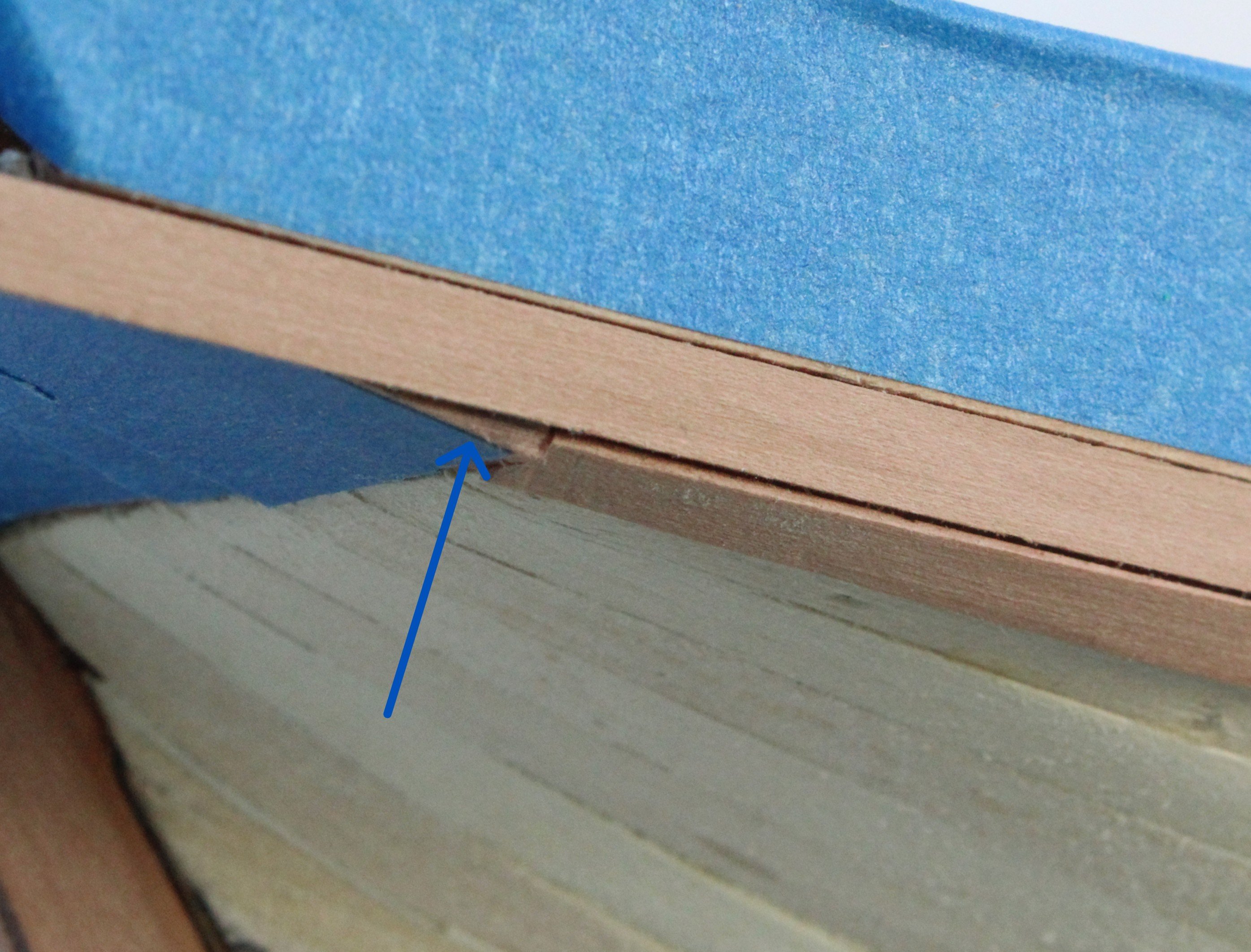
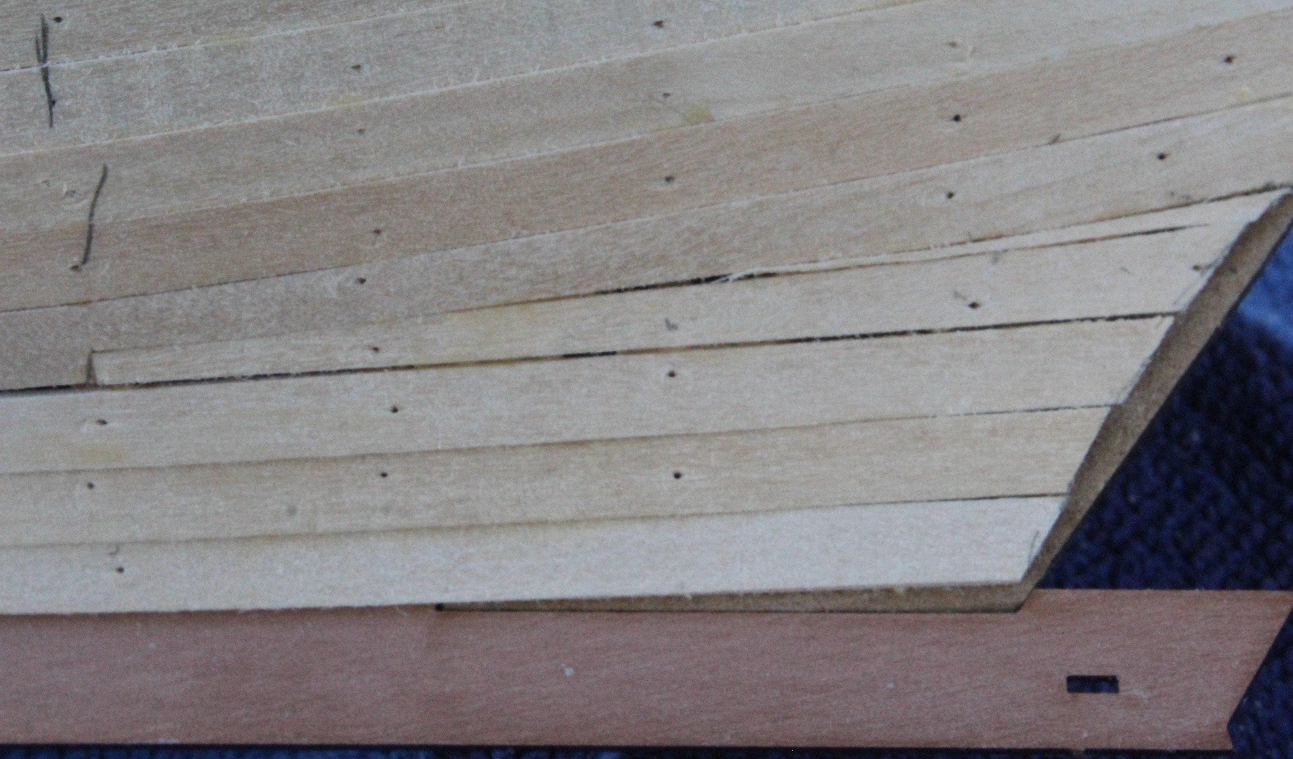
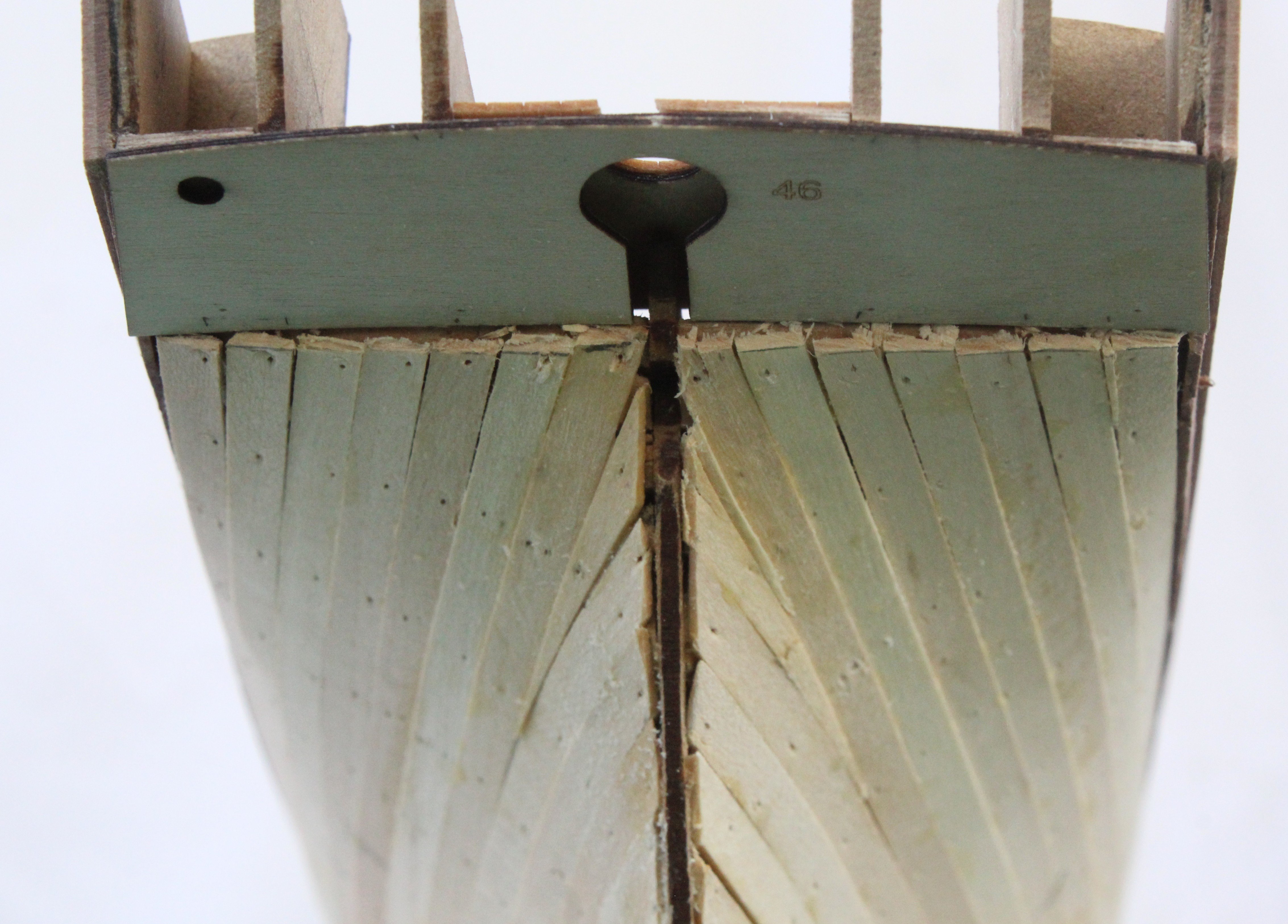
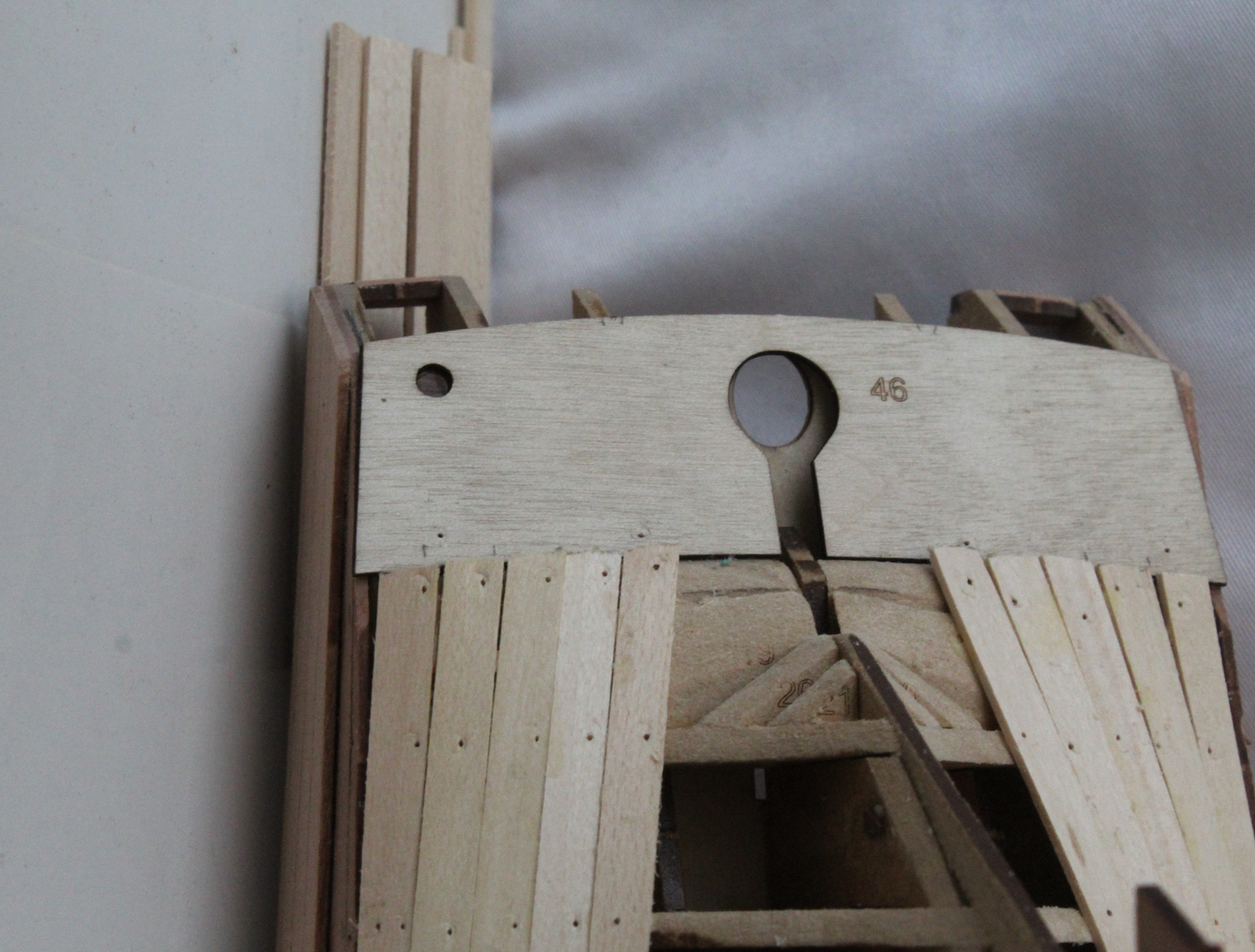
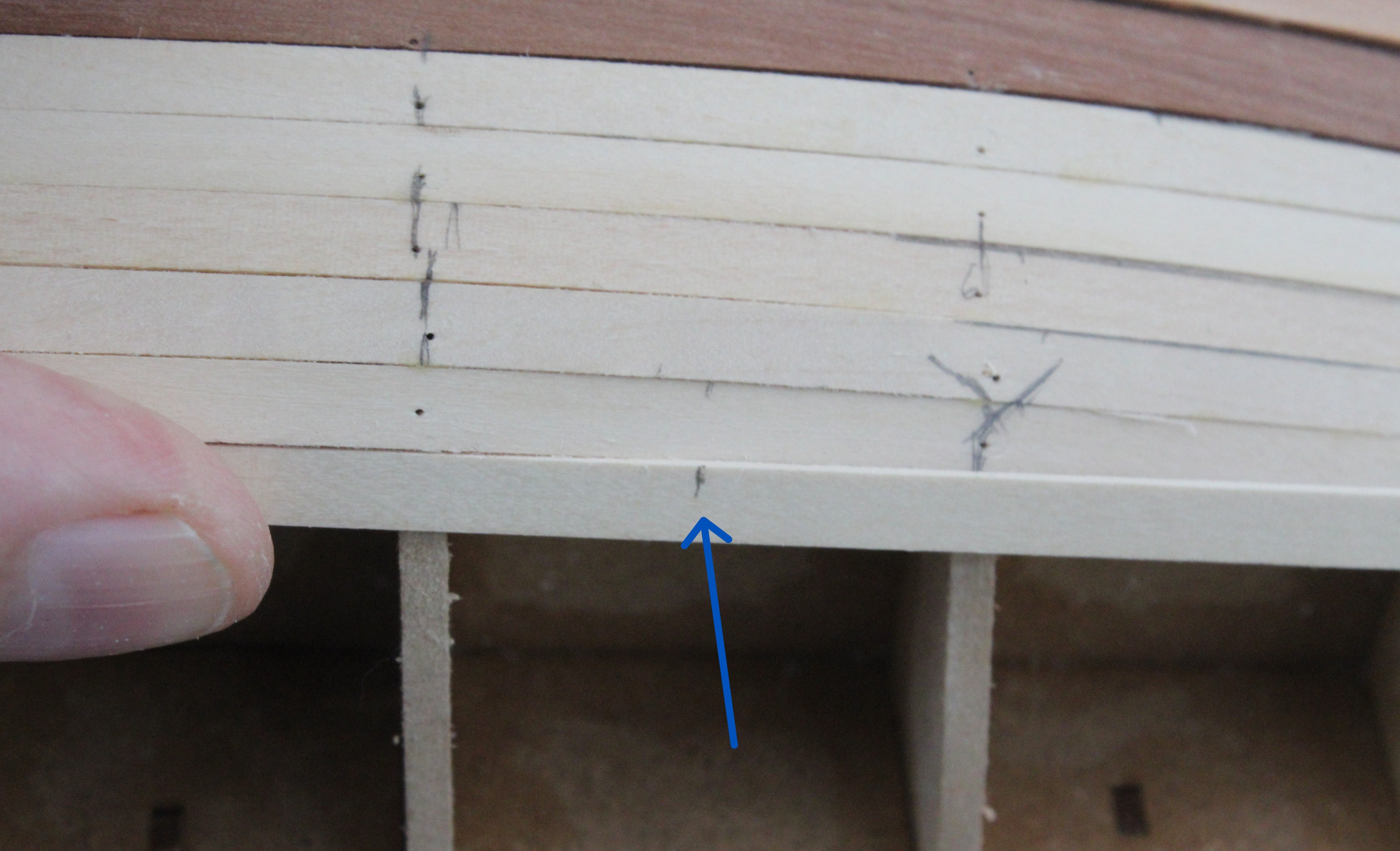
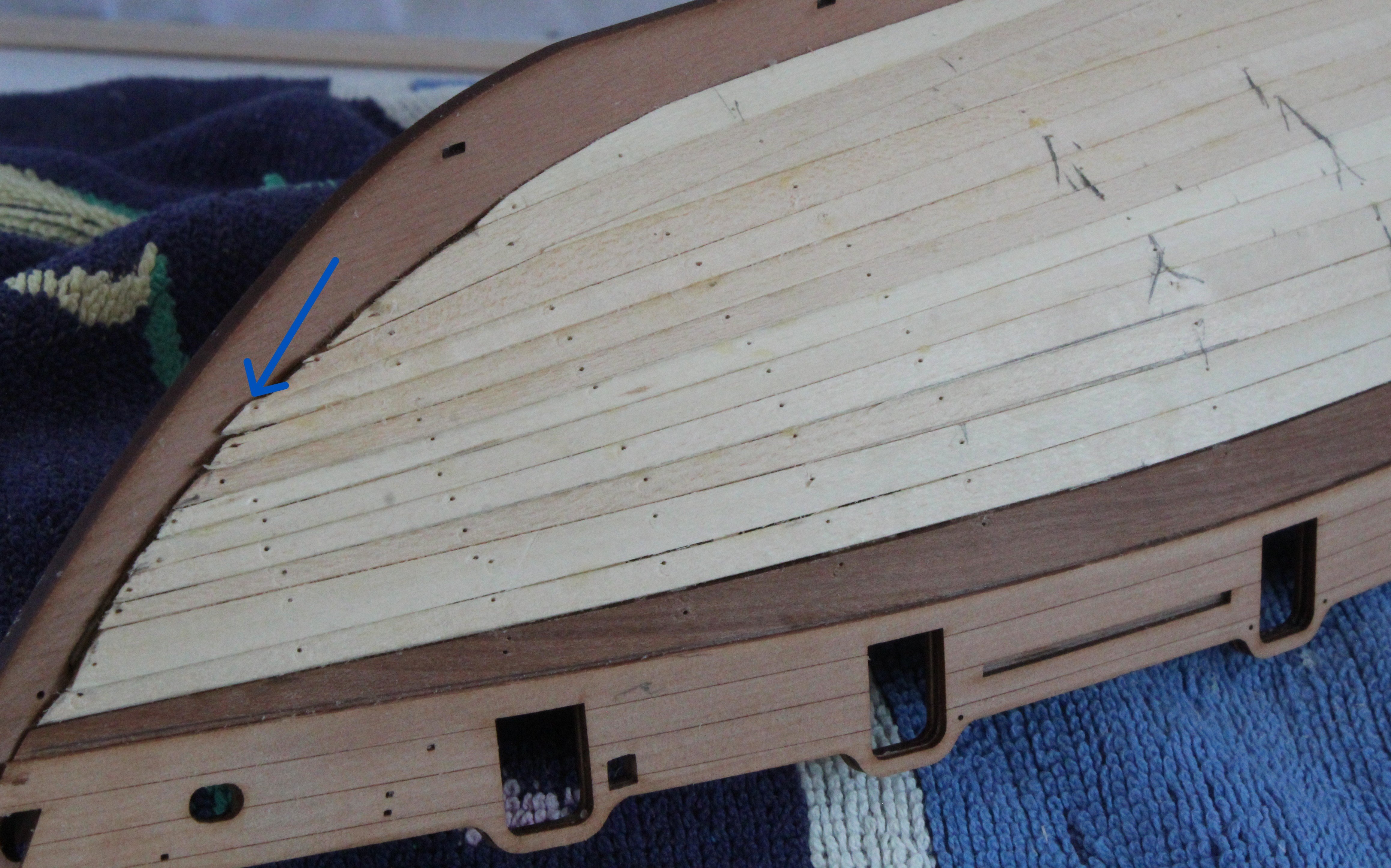
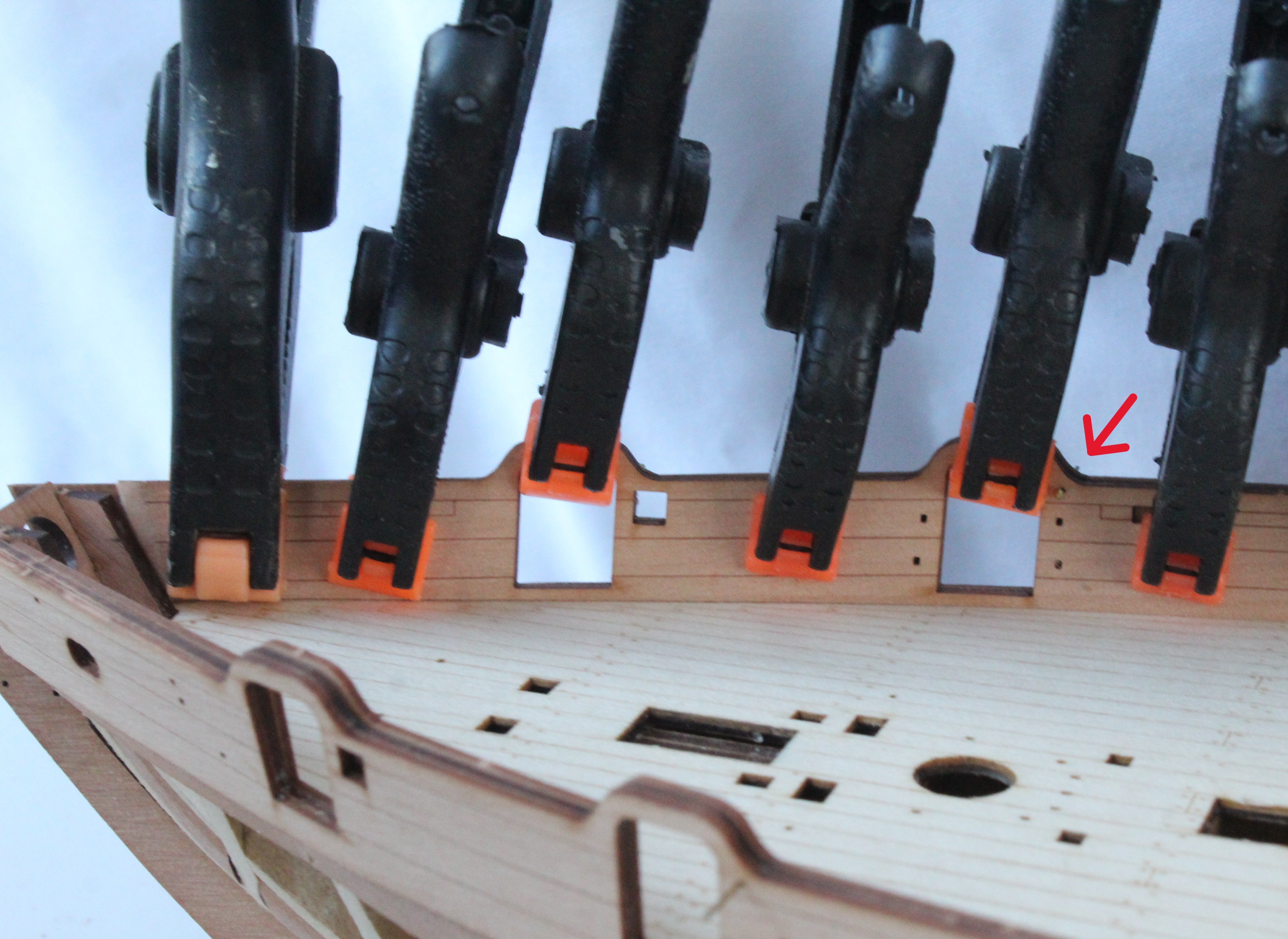
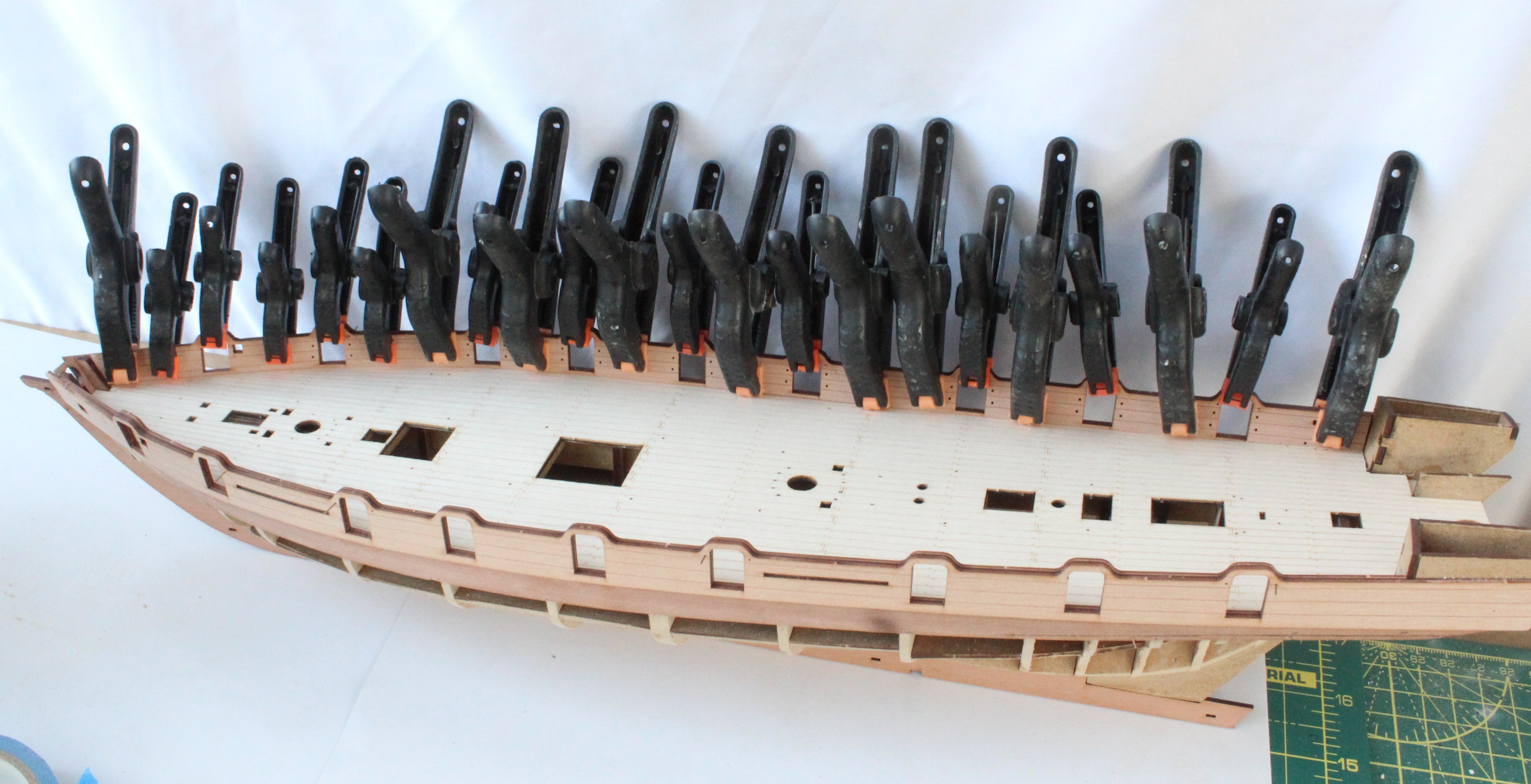
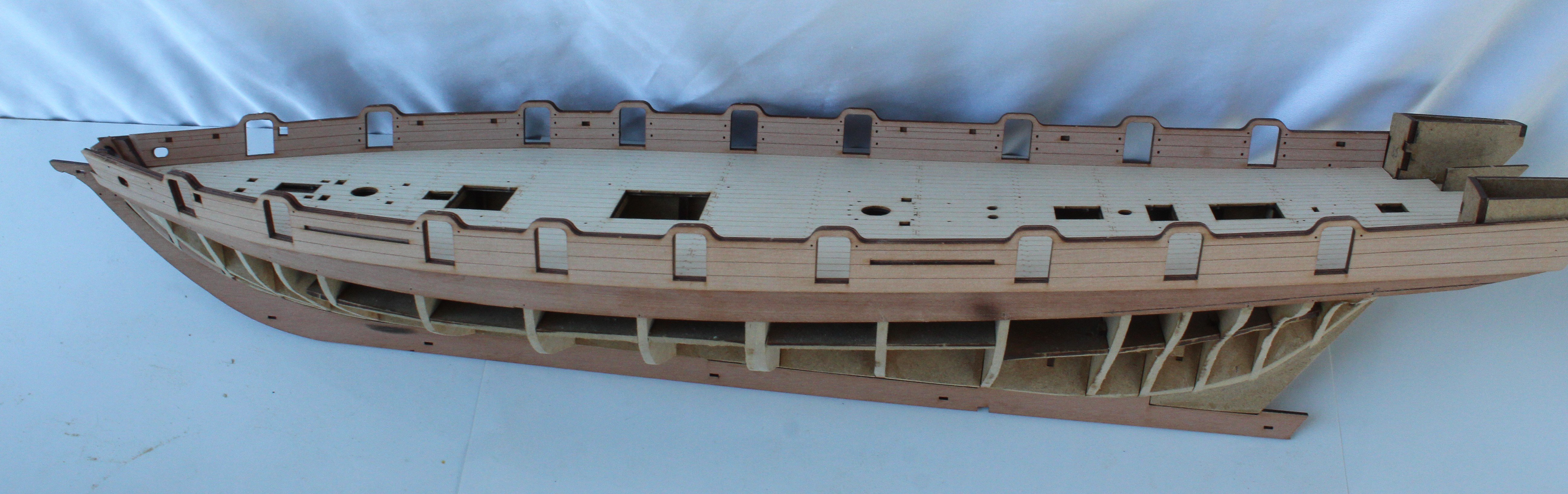
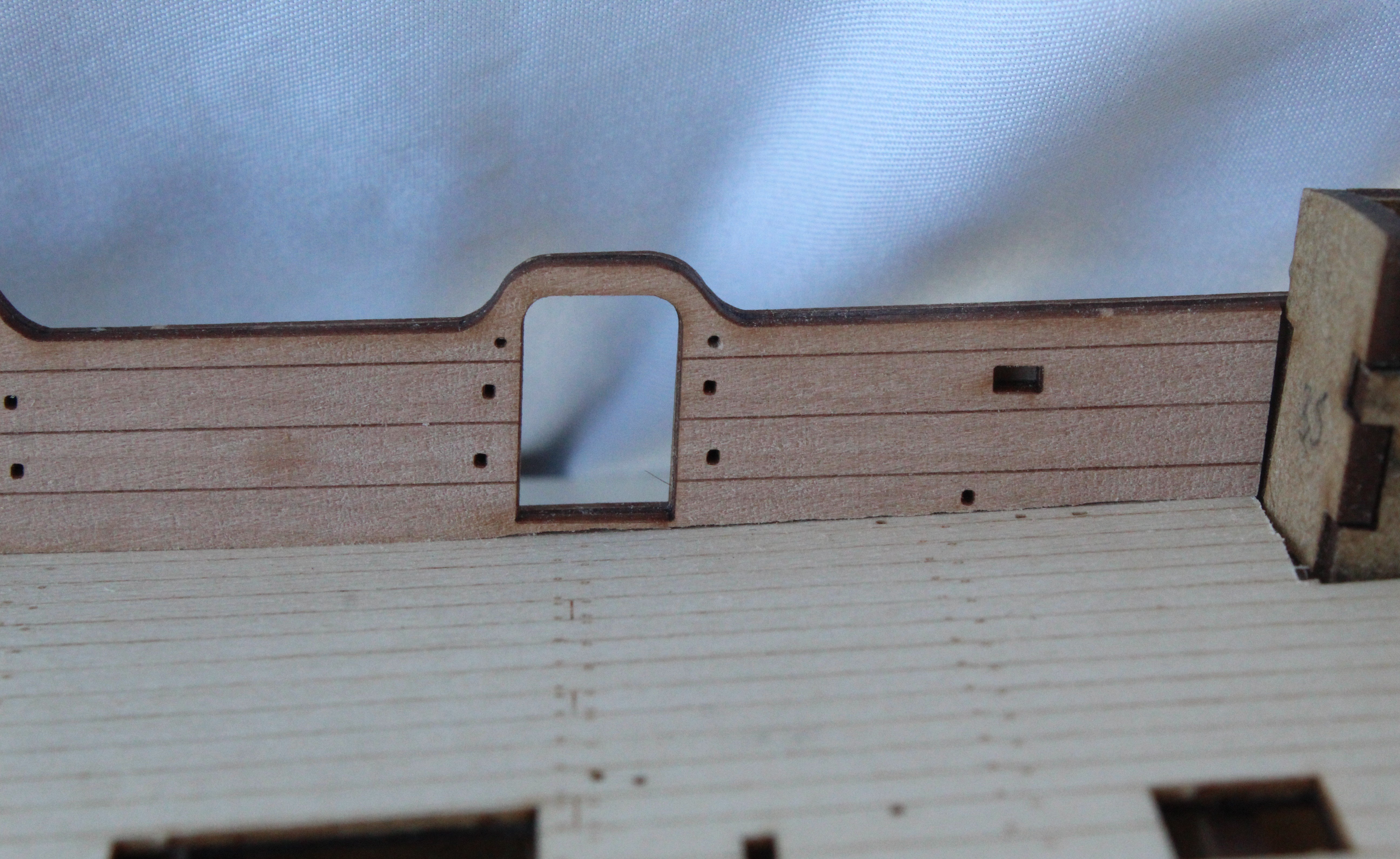
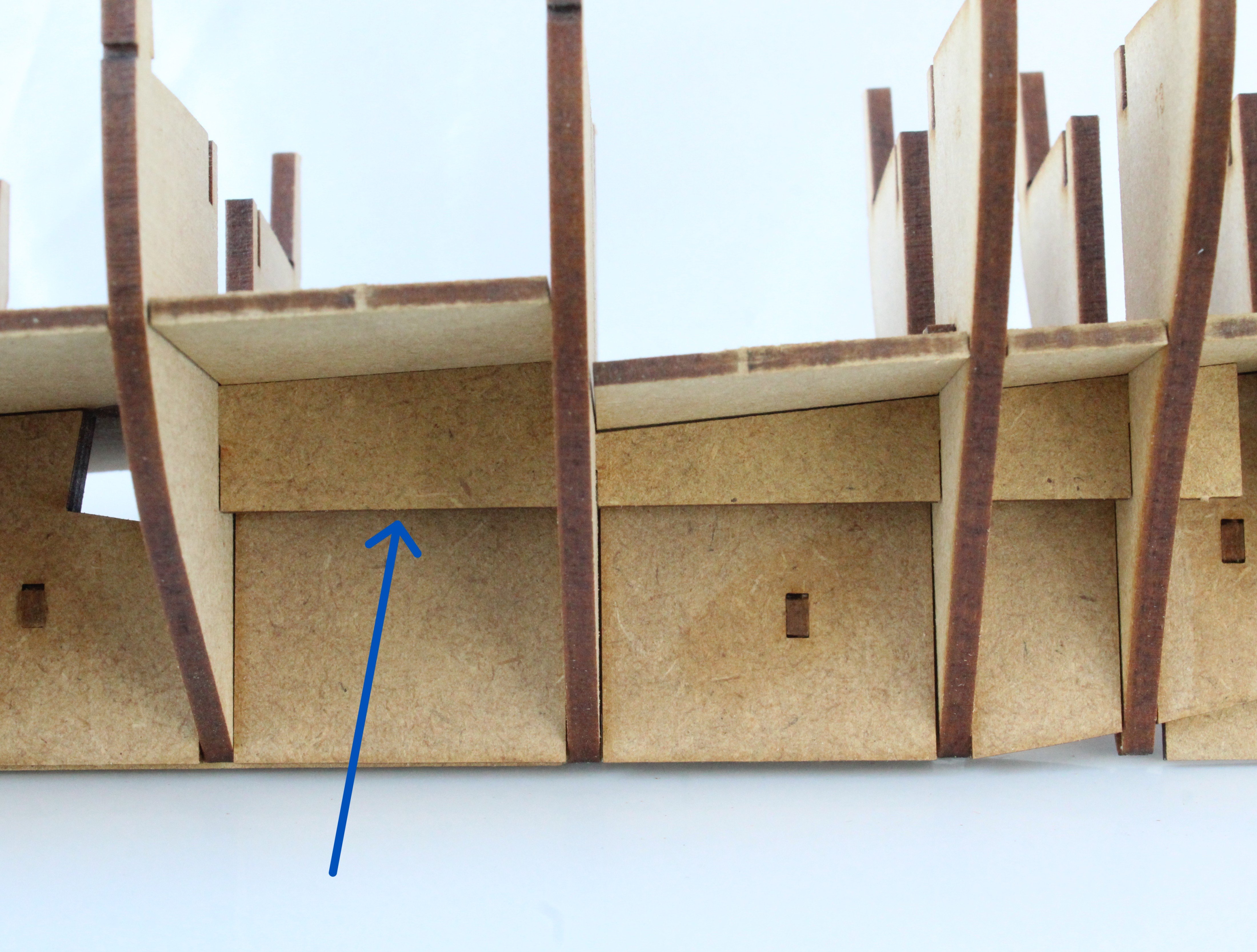
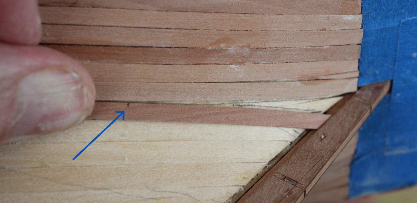
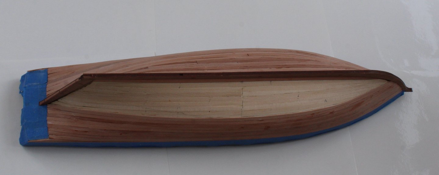
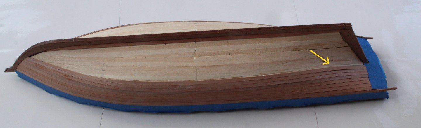
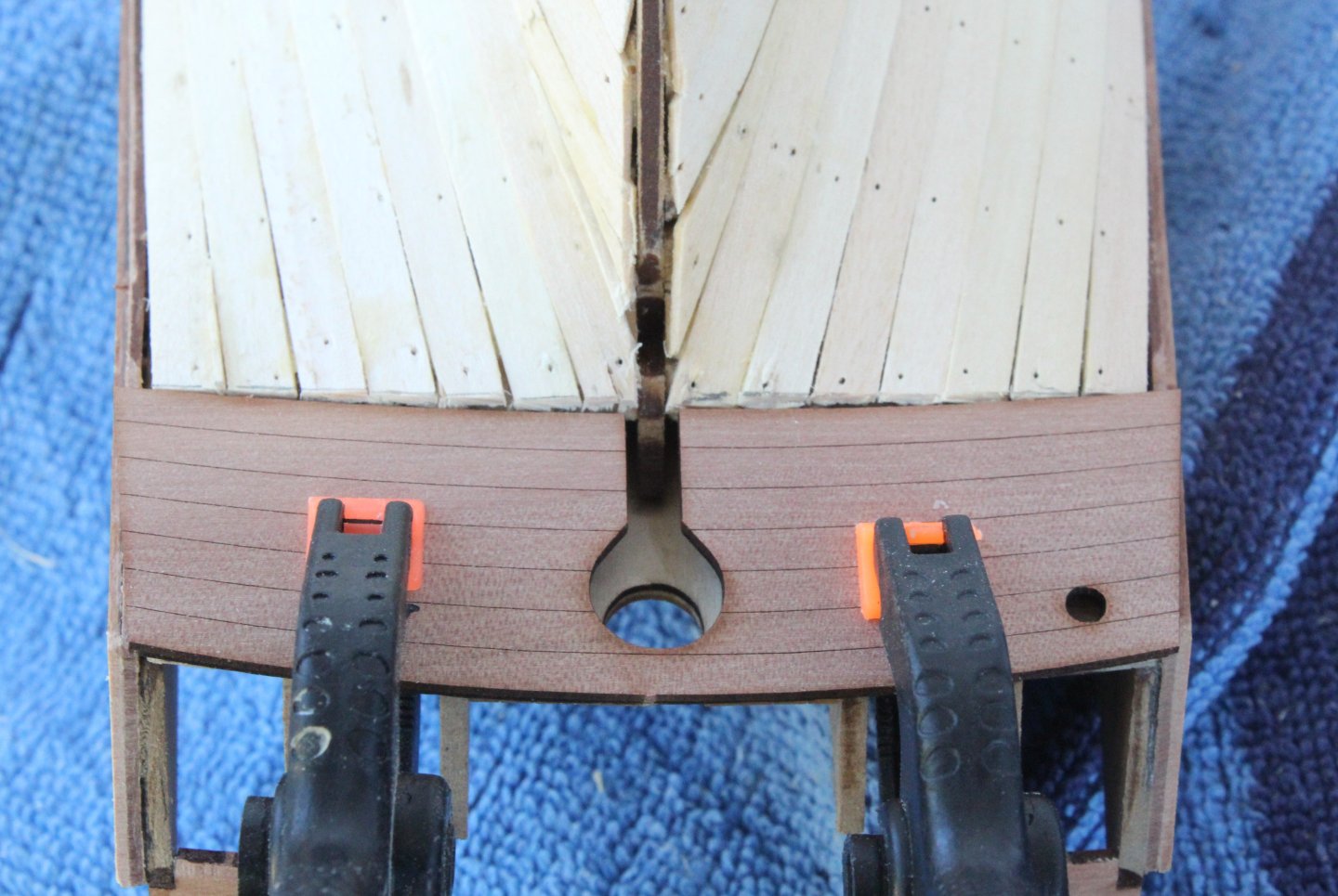
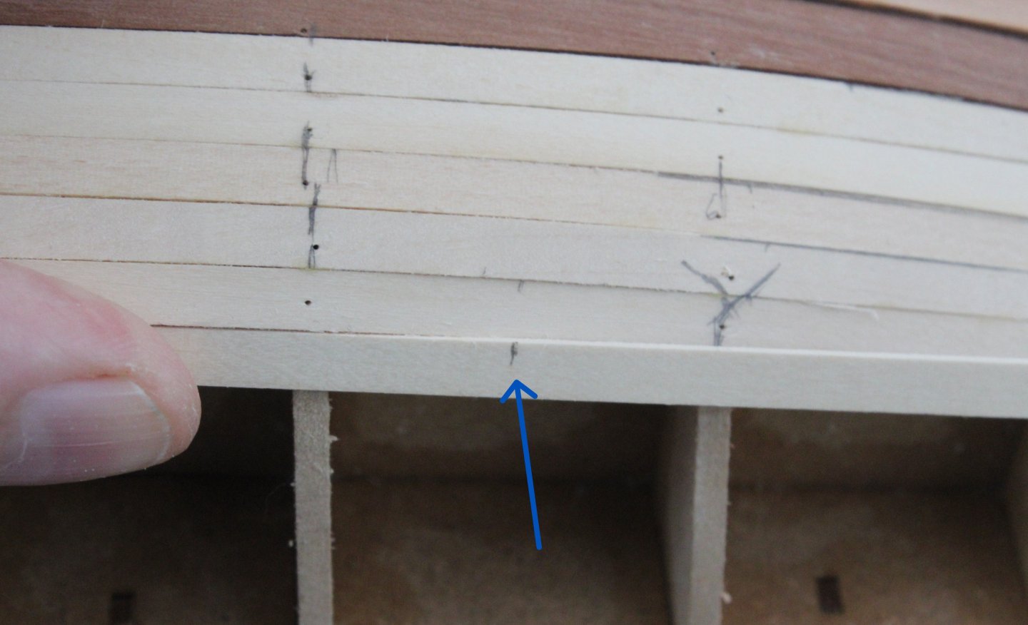
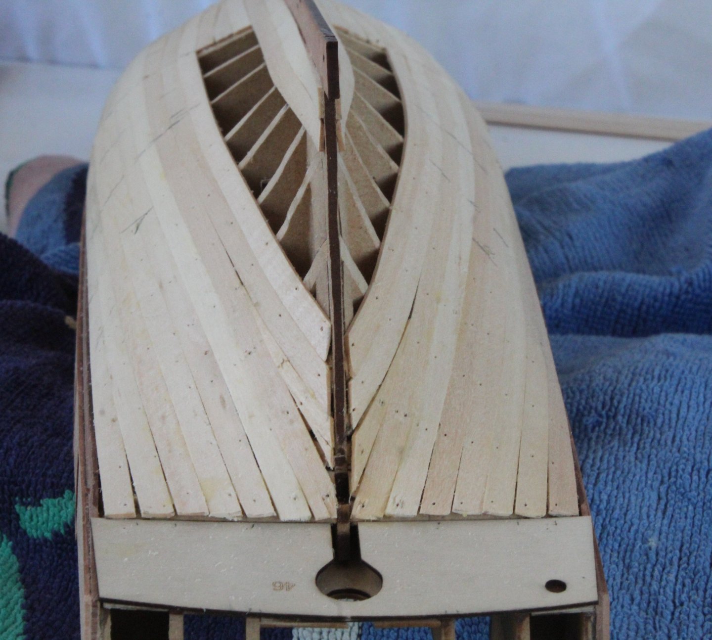
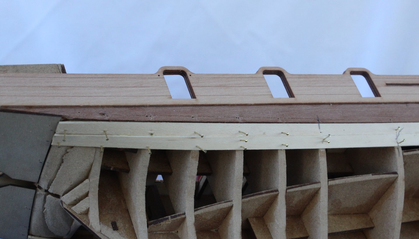
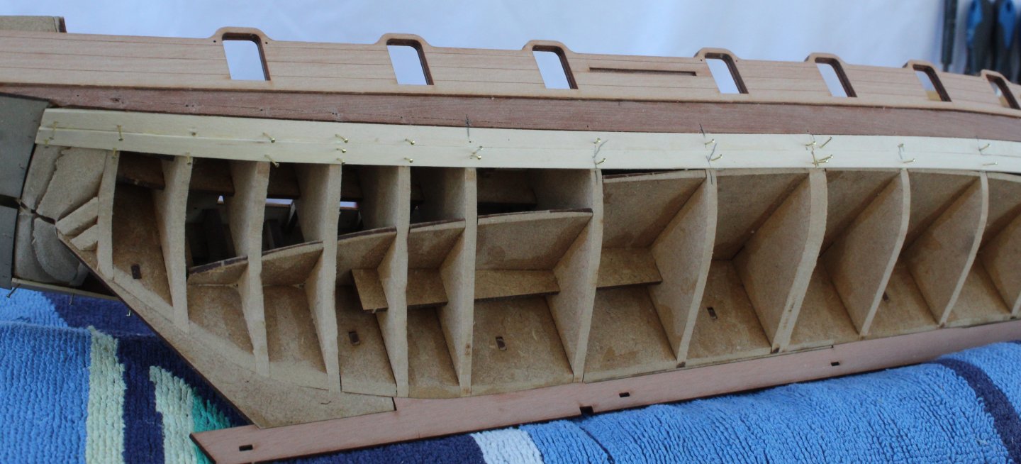
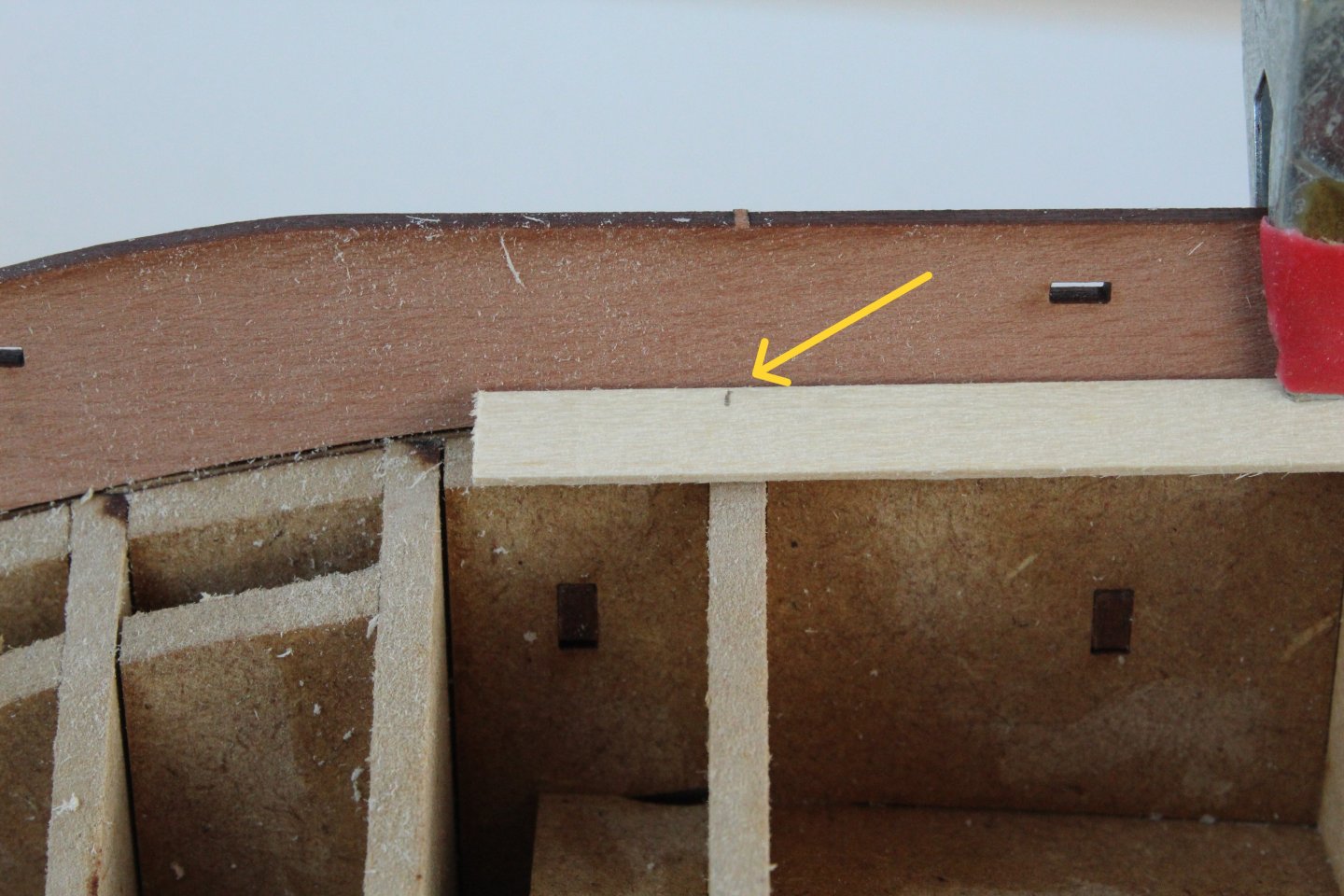
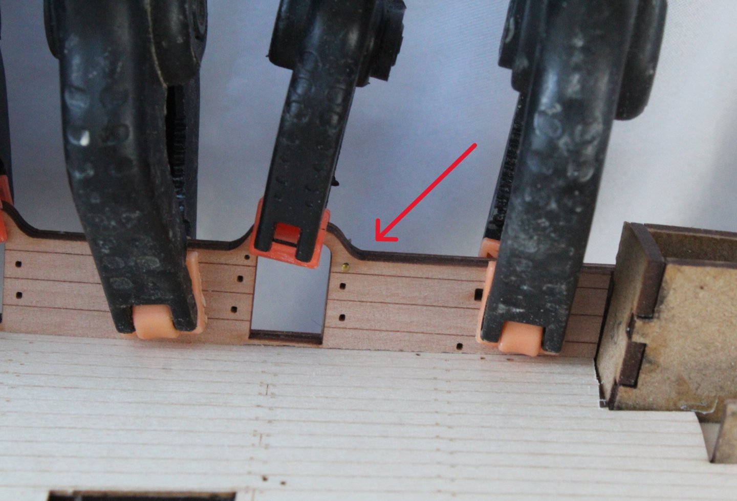
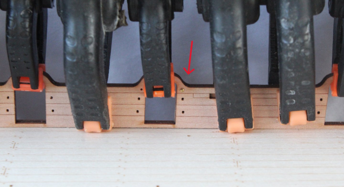
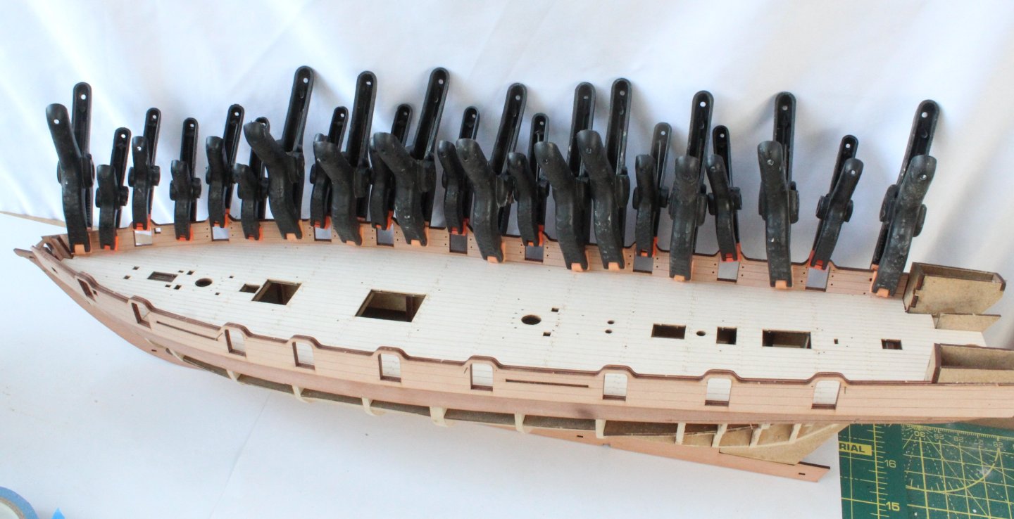
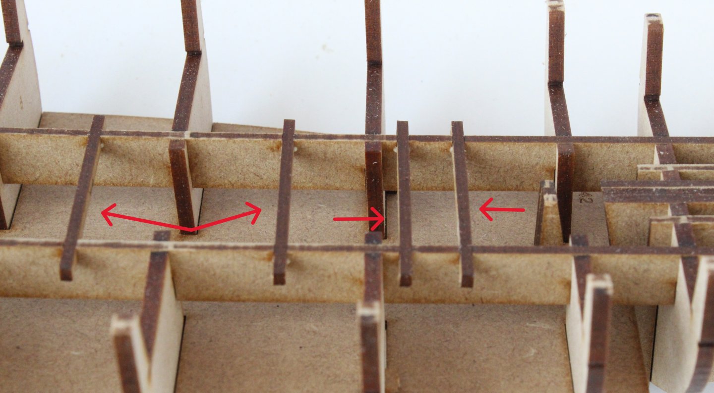
I am currently doing a running challenge to raise for cancer research as my wife is currently undergoing treatment for stage 4 cancer which we've been told can be treated and managed with drugs and probably surgery. Further details can be found on my Facebook page. The second planking is progressing slowly. I have added 9 downward planks so far and so far I am pleased with how they look. I have started to laterally bend the tapered planks which really helps with the fit around the bow. The stern area is not too bad either, noting I will need to trim some of the planks. I didn't notice until I tool this photo that I will have to try to release one plank and reset as it has not been glued, as shown by the arrow below. I have also added the garboard plank. In the first two photos below I am test fitting the plank. I did use a carboard template to get the right shaping for the bow end. I opted to use wood glue for the garboard plank so plenty of clamps were used. All looked good once the clamps were removed.


-
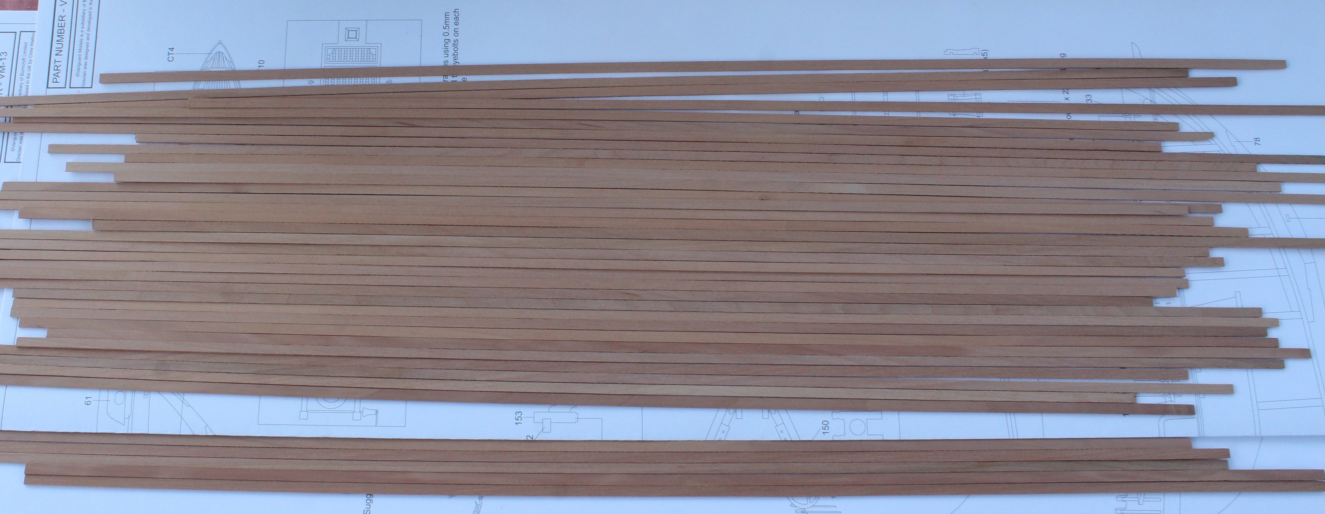
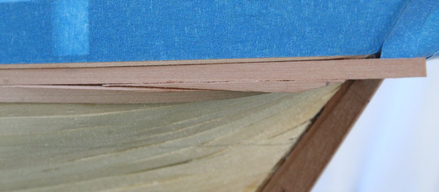
It did not take too much effort to sand the hull smooth. I did a few trial fits of the second planking as I went along to make sure I was happy, especially with the termination of the planks with the stern post and stern counter. Once that was done the keel outer patterns, stern post and outer stern counter pattern were glued in place, as can be seen below. Next task was to add the ready to the second planking. With the planks laid out I did colour match as there is quite a bit a variation between the kit supplied planks. It not really an issue as the hull will be painted and copper plated. The first two rows of planking have now been fitted to each side. Close up of the bow area. And now a close up of the right hand side stern area. I will need to add a small filler piece as indicated by the arrow. And now a close up of the left hand side stern area, noting the small filler piece has been fitted.


-
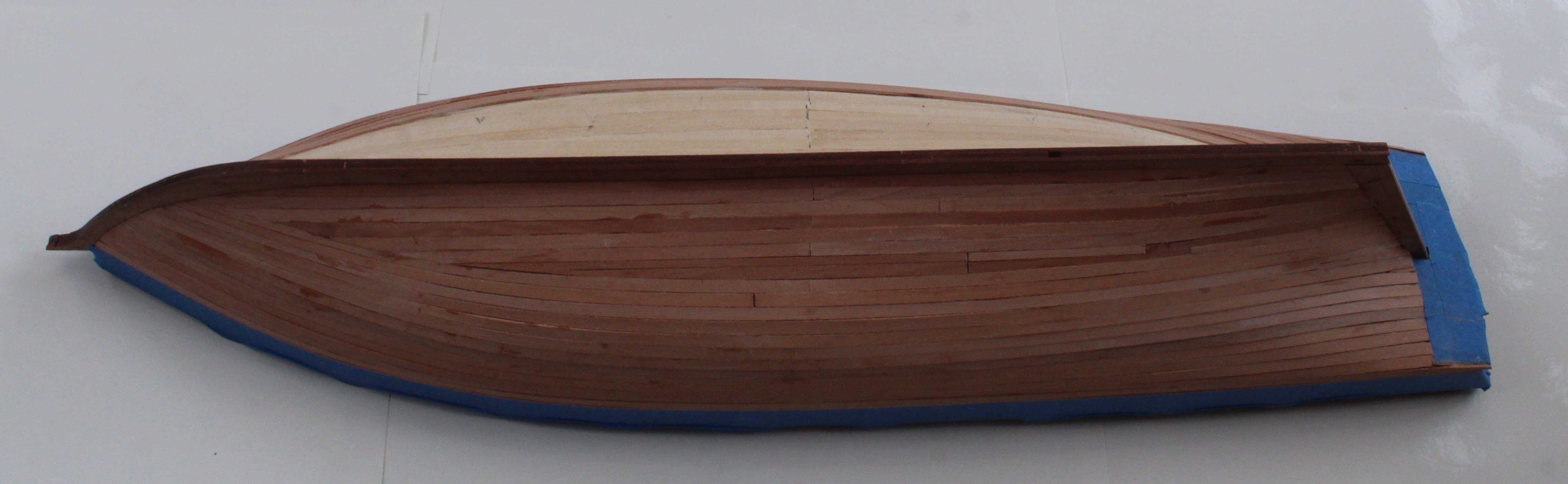
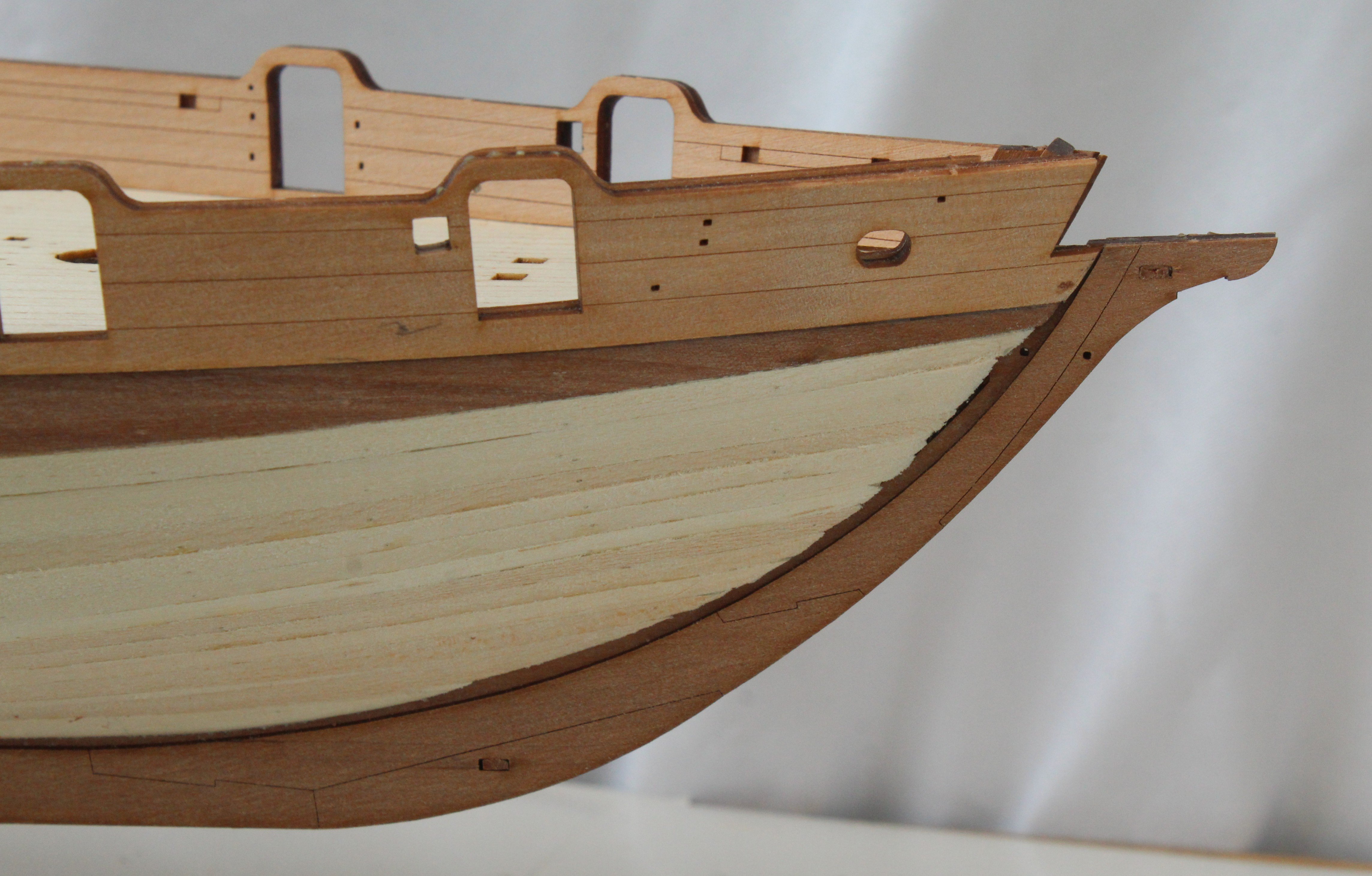
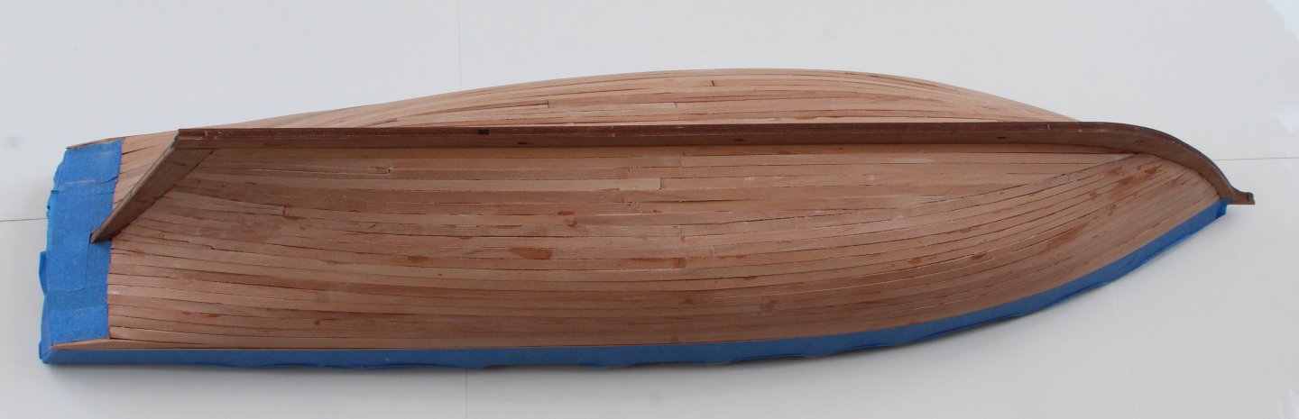
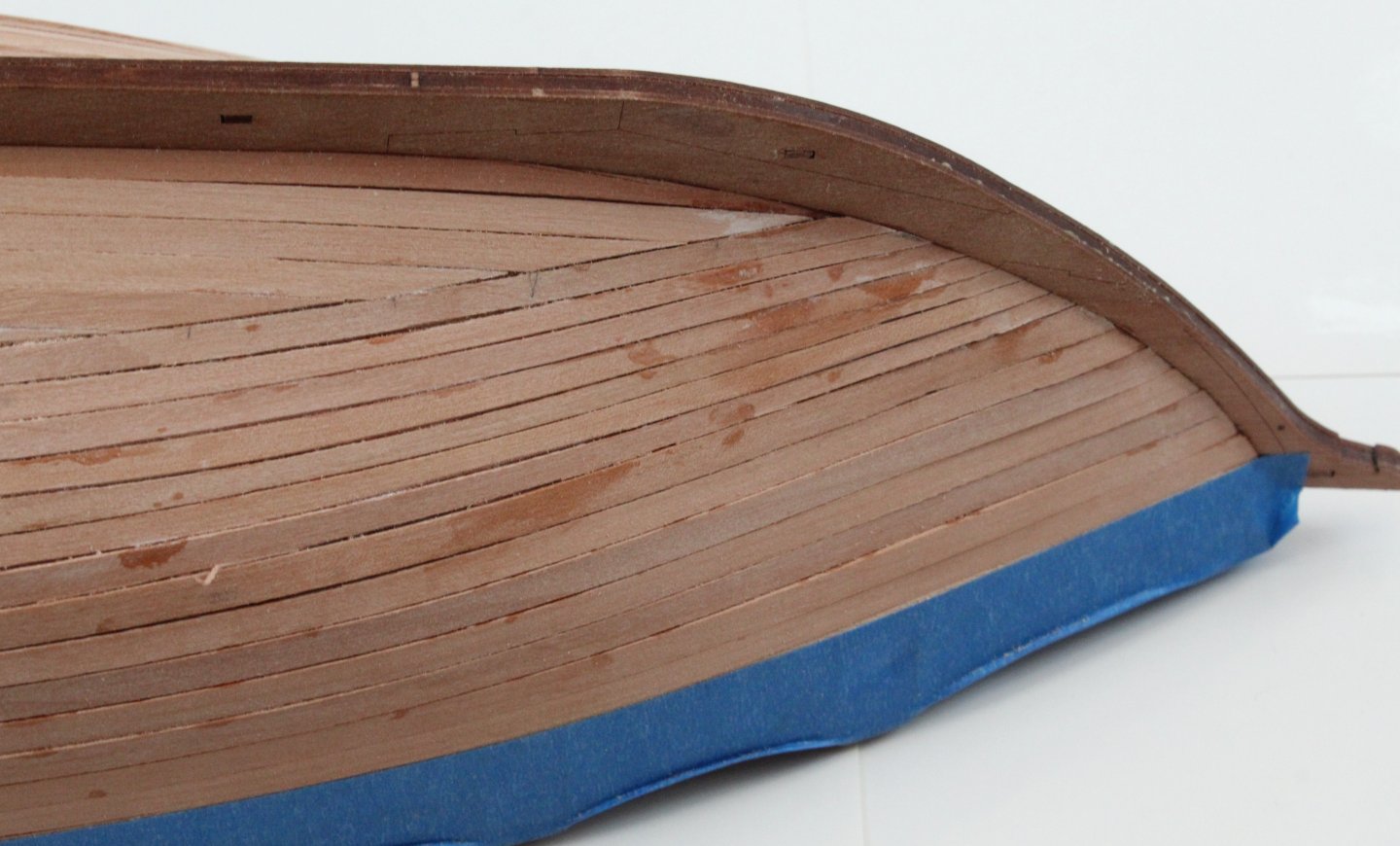
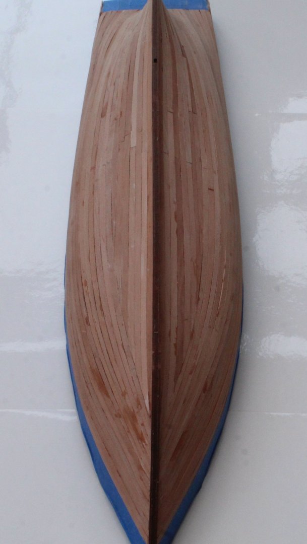
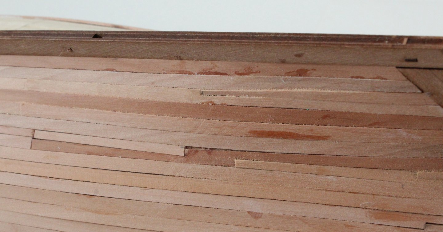
I have now completed the first planking of the Grecian hull. This was an easy hull to plank and I am reasonably pleased with the outcome. As can can seen in the first photo below I did have to add a steeler. You will also note I did also add a very small filler piece above the steeler. The completed planked Grecian hull is now shown in the next two photos. To complete the set I have added a photo of both the bow and stern areas. Before moving on to sanding the hull I decided to do a dry fit of both the stern counter outer pattern and the keel outer patterns. I did have to slightly trim the plank edges so the stern counter outer pattern was aligned with the inner pattern.


-
Looking good Jim, great work as always.
-
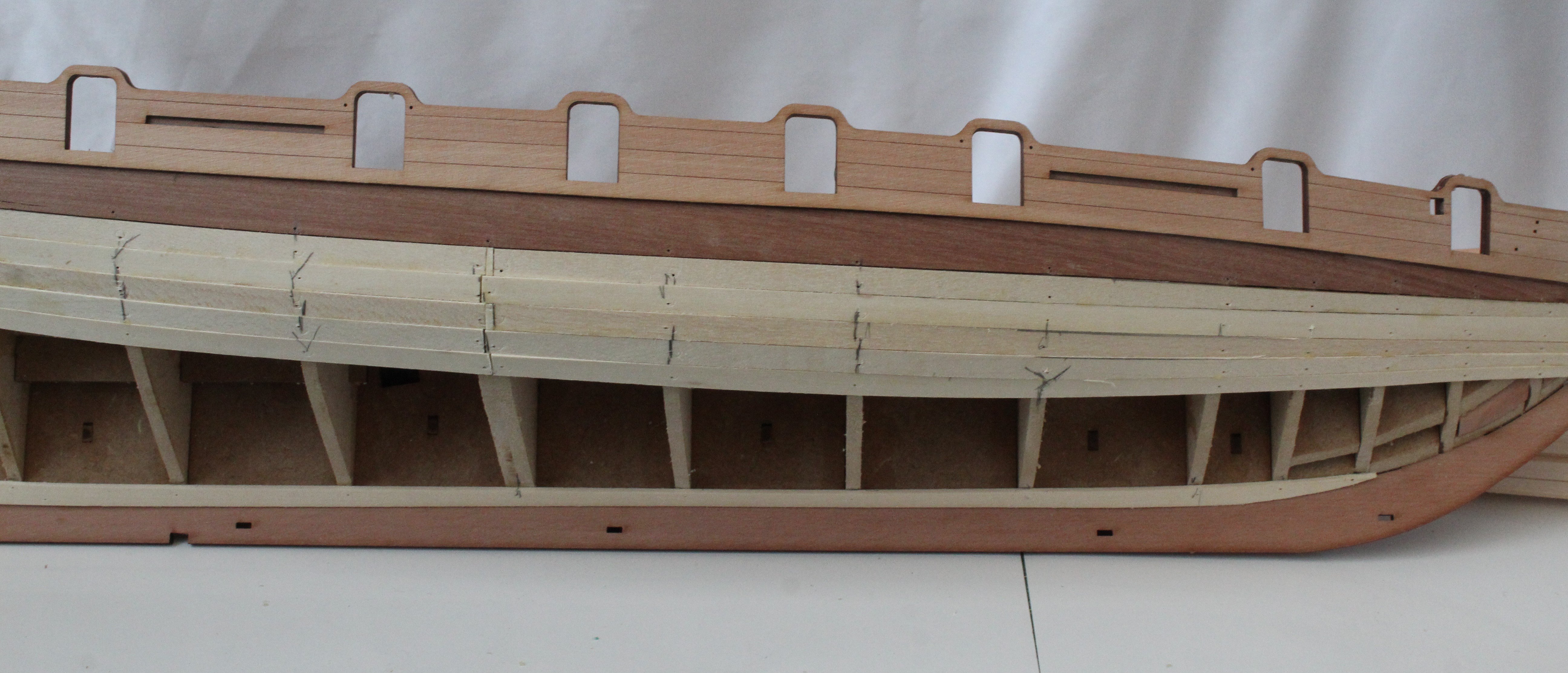
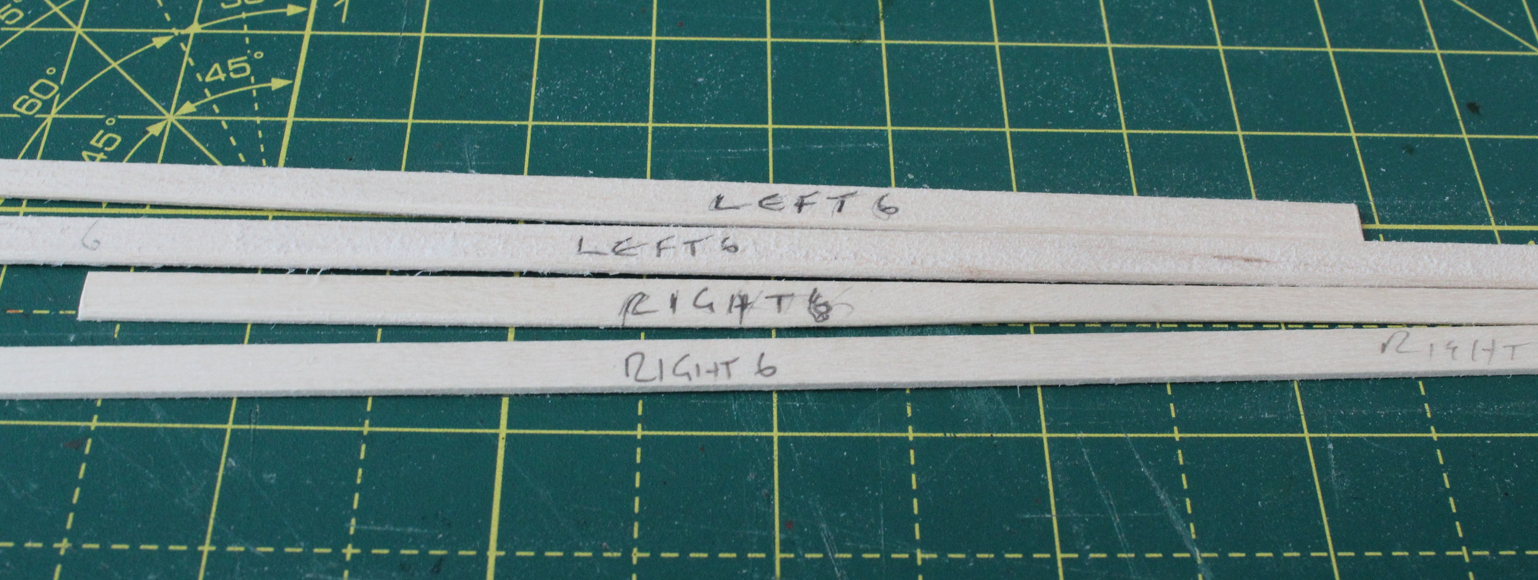
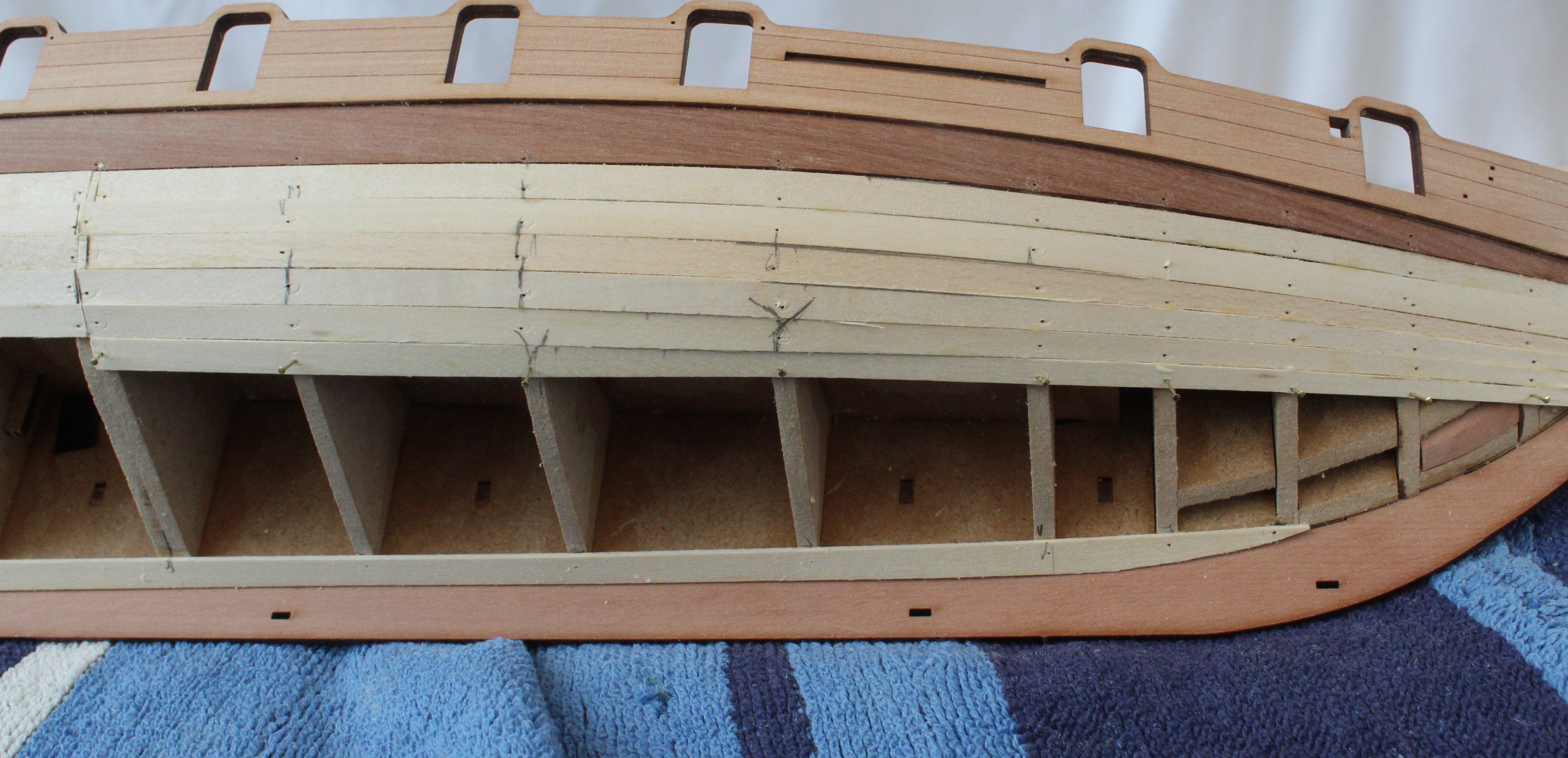
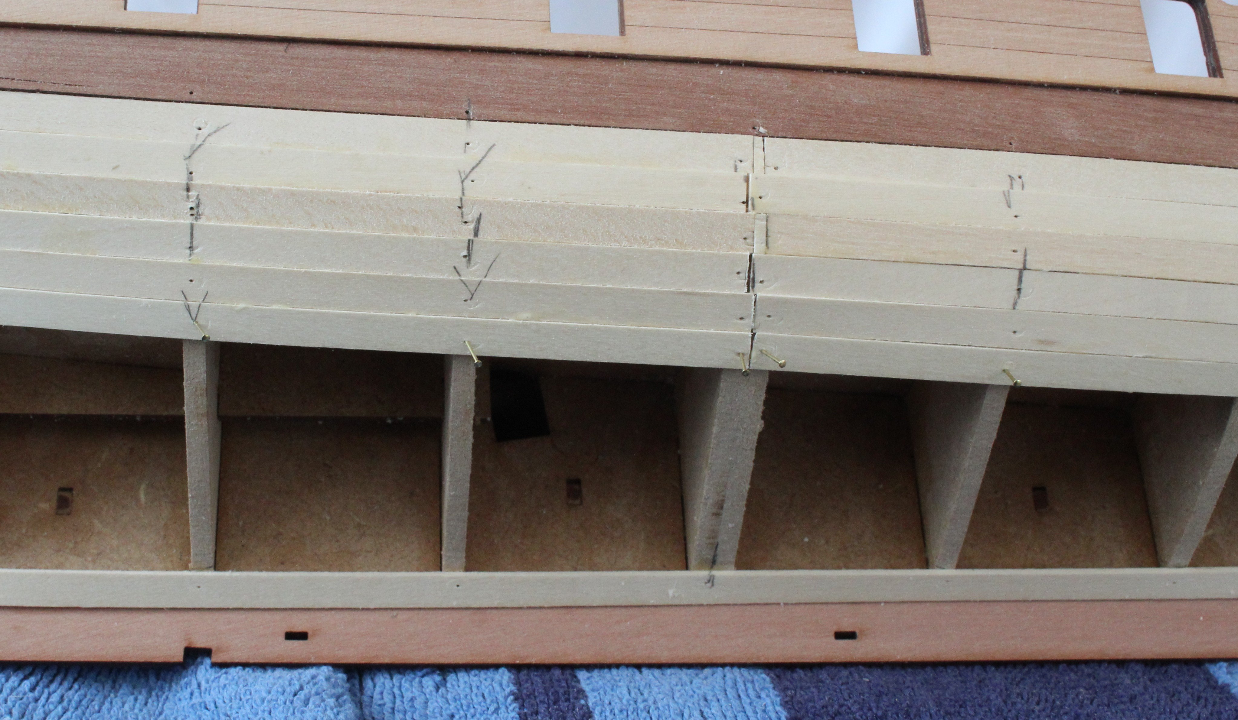
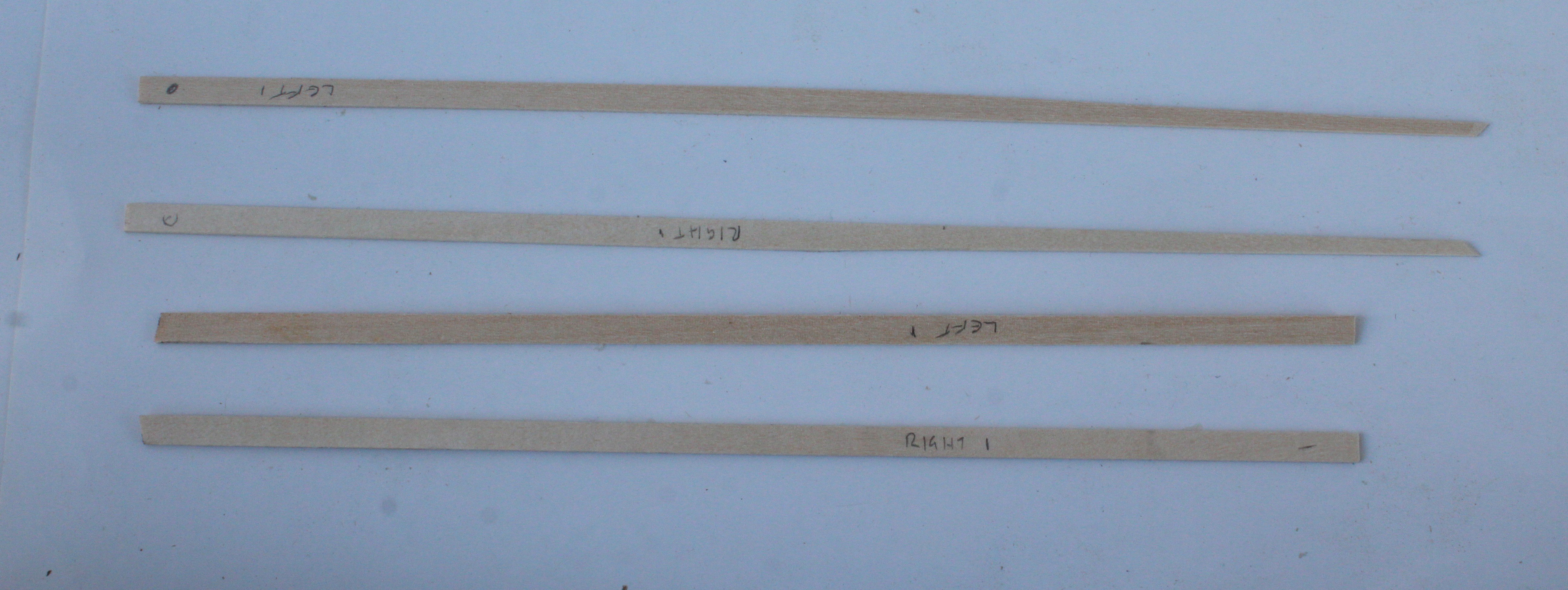
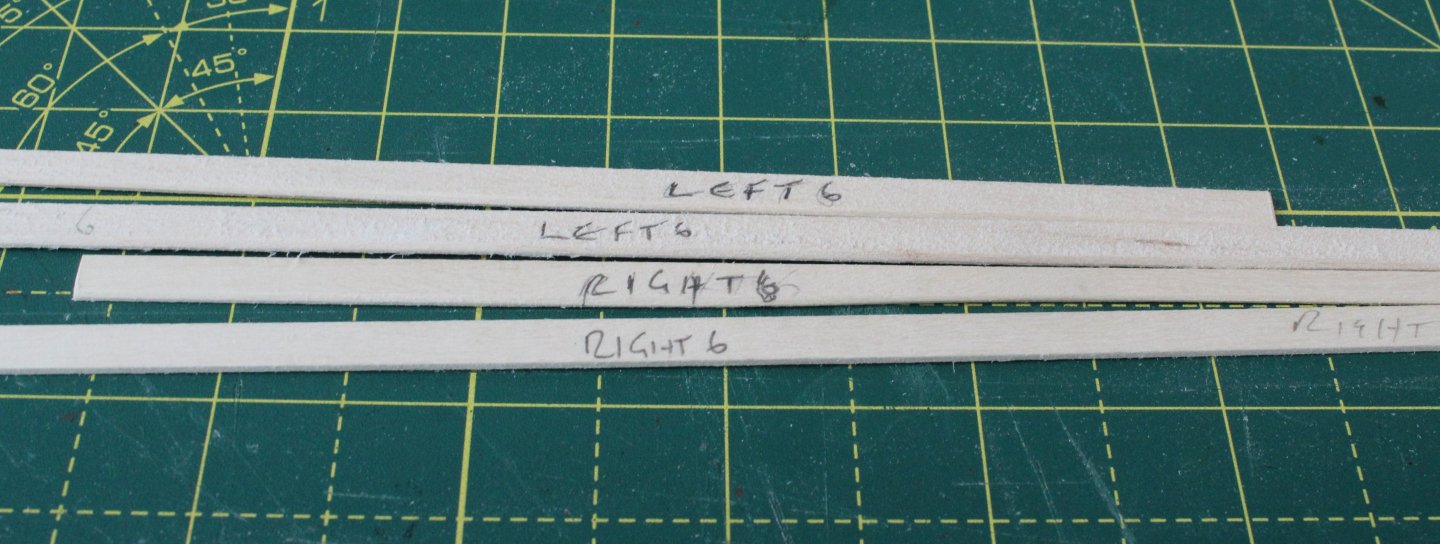
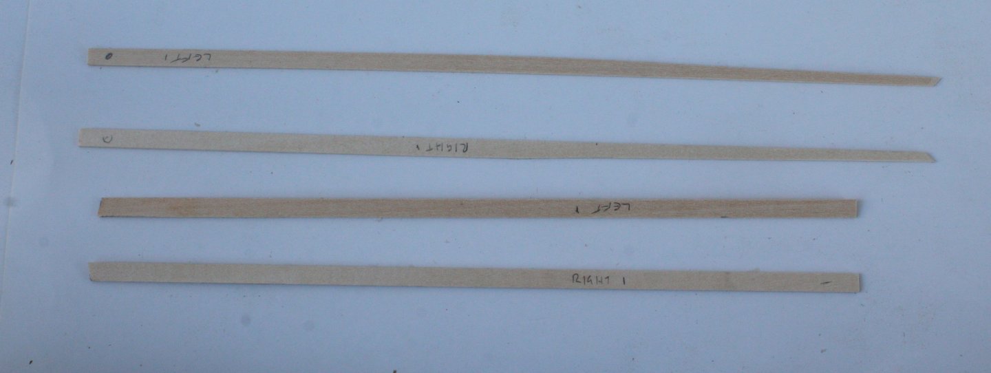
After a short break away I am now back in the shipyard and I have made very good progress with the first layer of planking. The first 5 downward planks (both sides) have been fitted in the first three photos below. In the next few photos I am showing the method I have been using for fitting the planks. Each strake comprises a bow and a stern plank, which joins at the double width bulkhead. I always start with the bow strake and I shape the leading edge so it follows the bow curve. Next I determine and mark the crossover point. Once the plank has been tapered the planked it is held in place so its position can be marked. This makes the fitting, after the glue has been added, much easier as it is a very good point of reference. Next I shape the end of the stern plank And as per the bow plank I add a positional marker. The planks, left and right sides, are now ready to be glued in place. I have marled the underside with an identifier. The planks are then glued in place. This is how the hull looks after a few more planks have been added. The final set of photos show the completed bow section. I do need to trim on plank, as can be seen below. The stern section is almost complete. I am now in process of working out where to add the stealers. It will not take too much effort to complete the planking.


-
So far it has been an easy hull to plank, that said I am going very slowly at the moment makings sure I am happy with how strake looks before I glue in place. Fingers crossed it will continue to be relatively straightforward, so far there has been no need for any lateral plank bends which is a bonus.
-
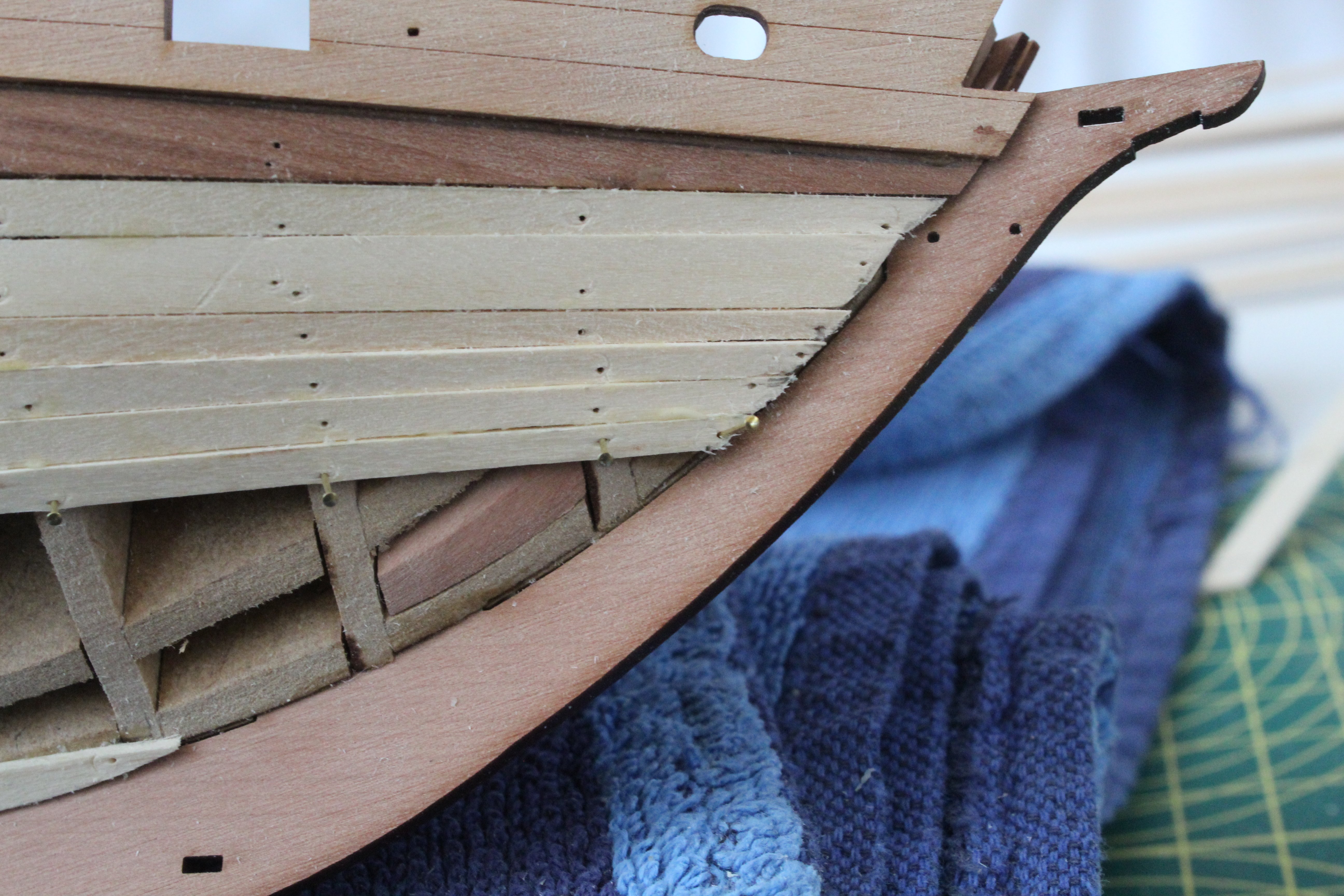
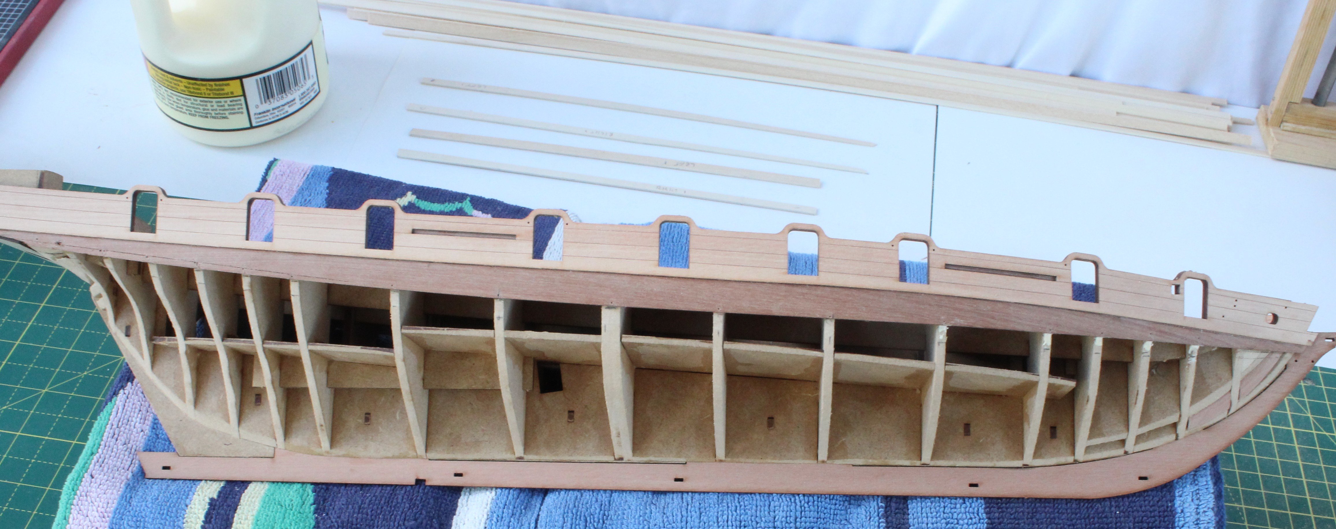
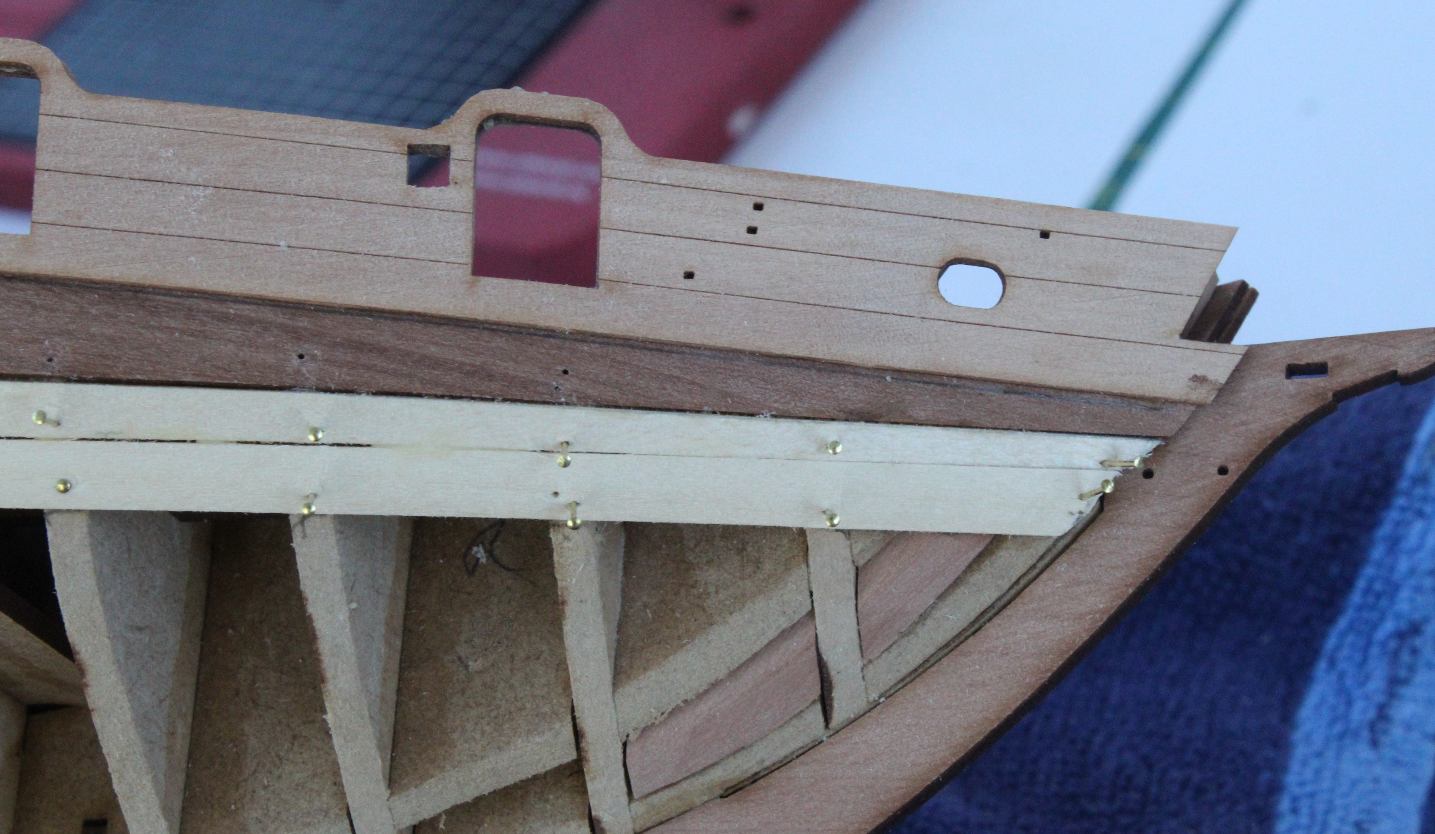
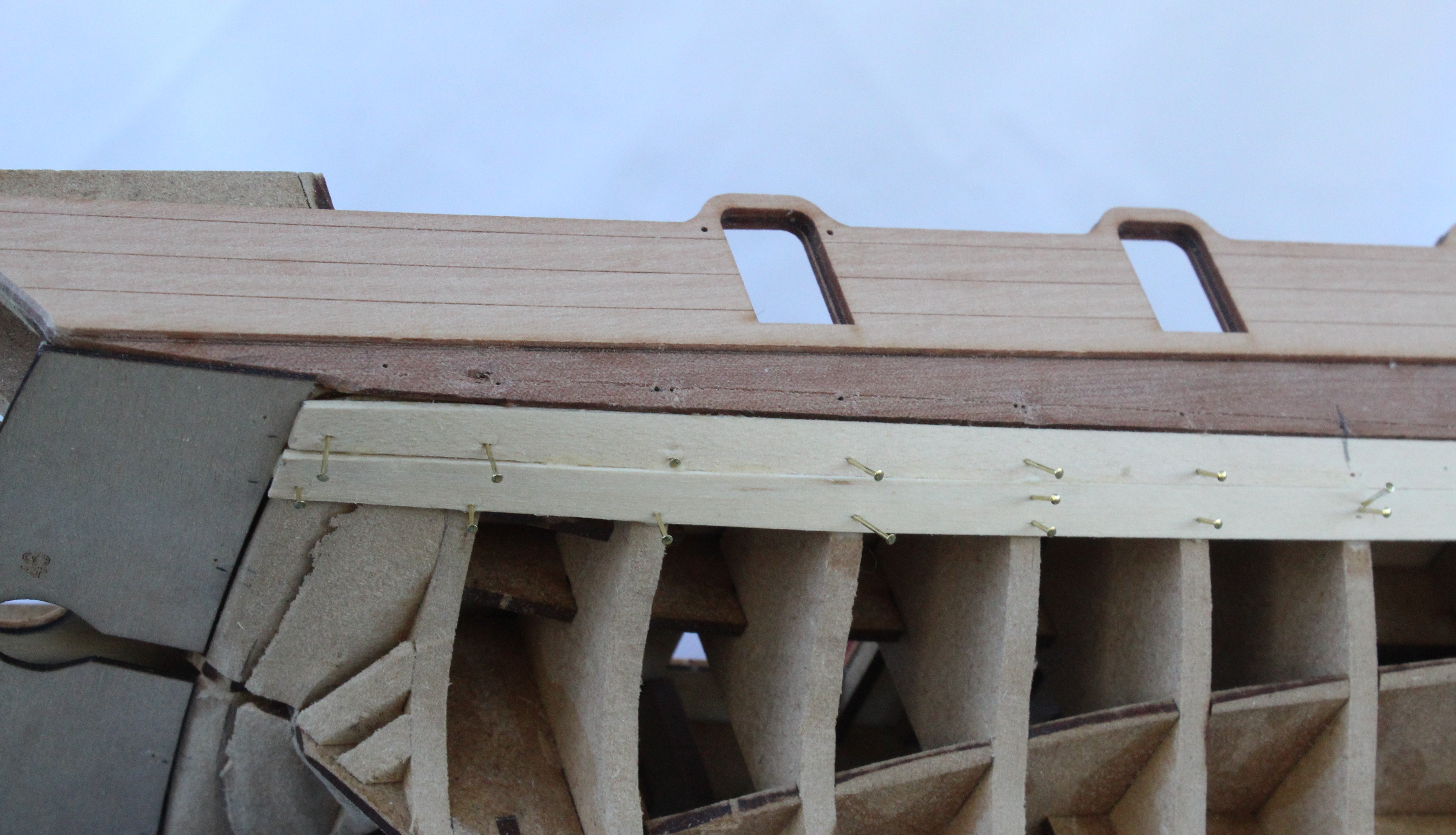
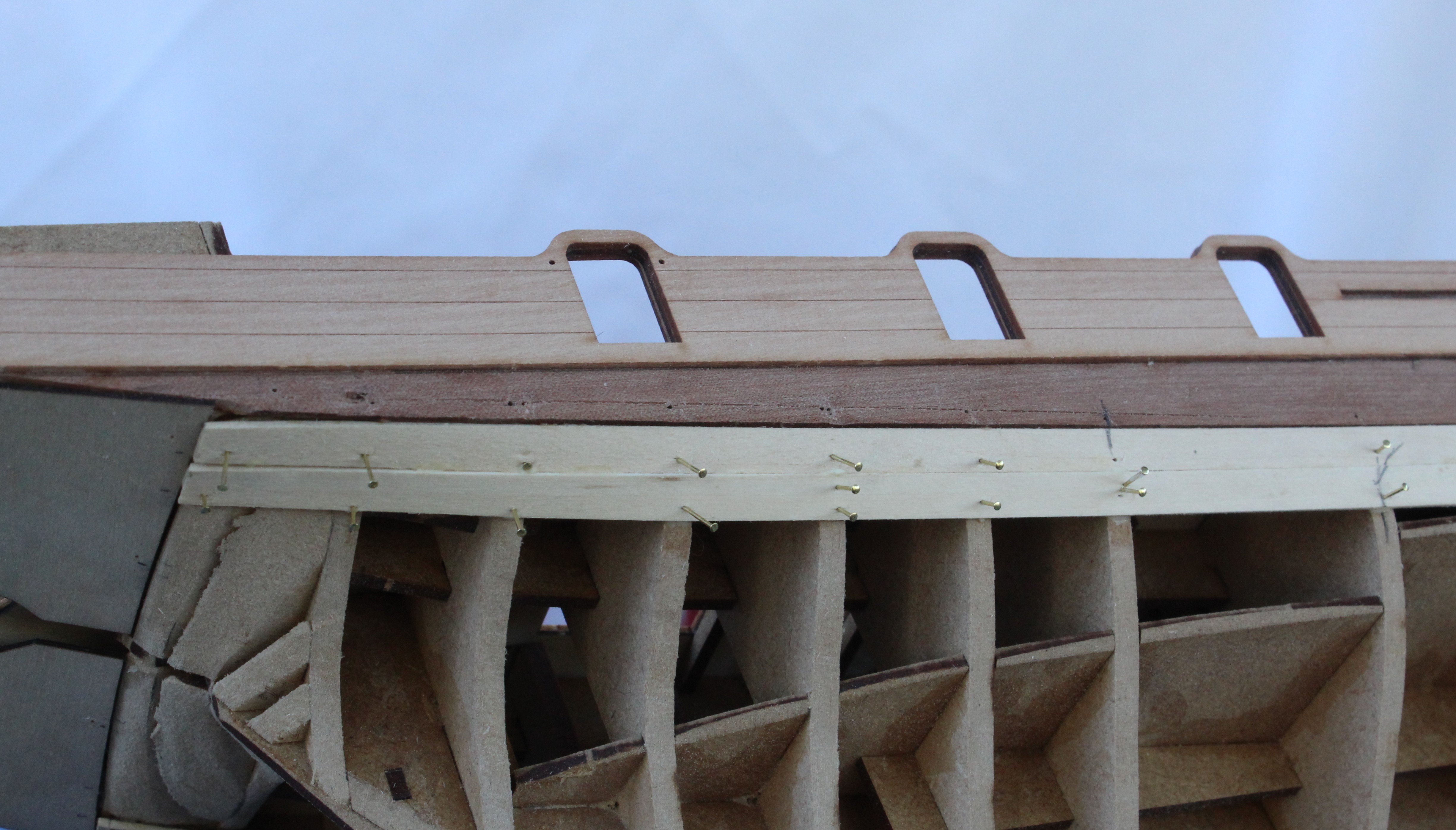
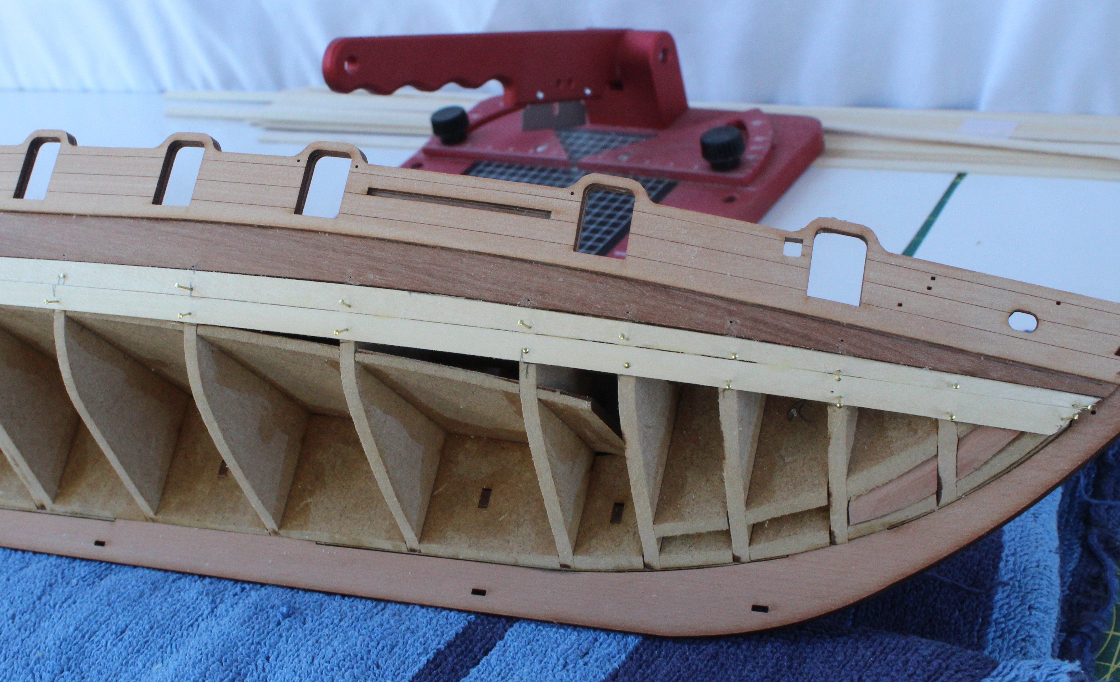
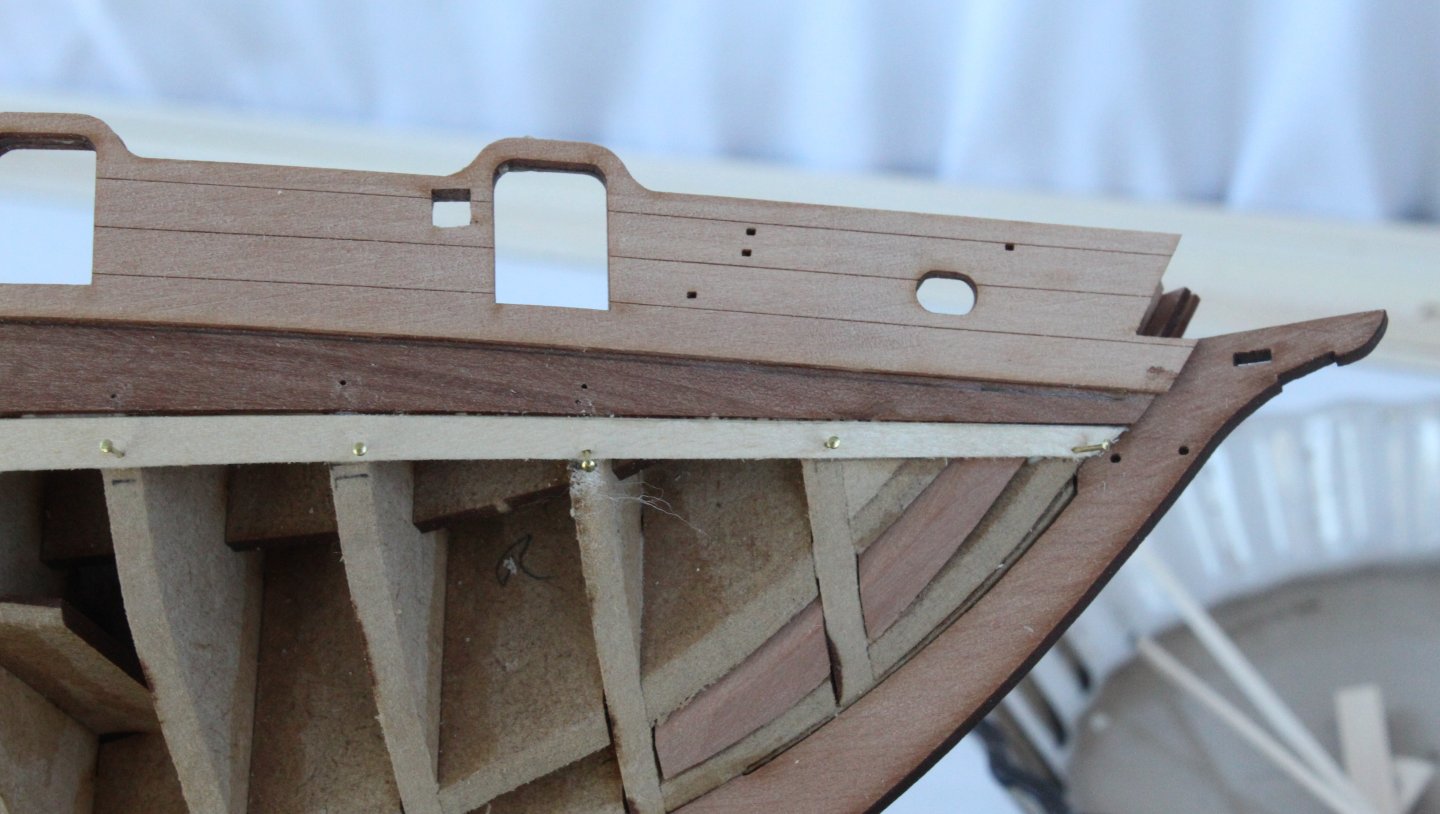
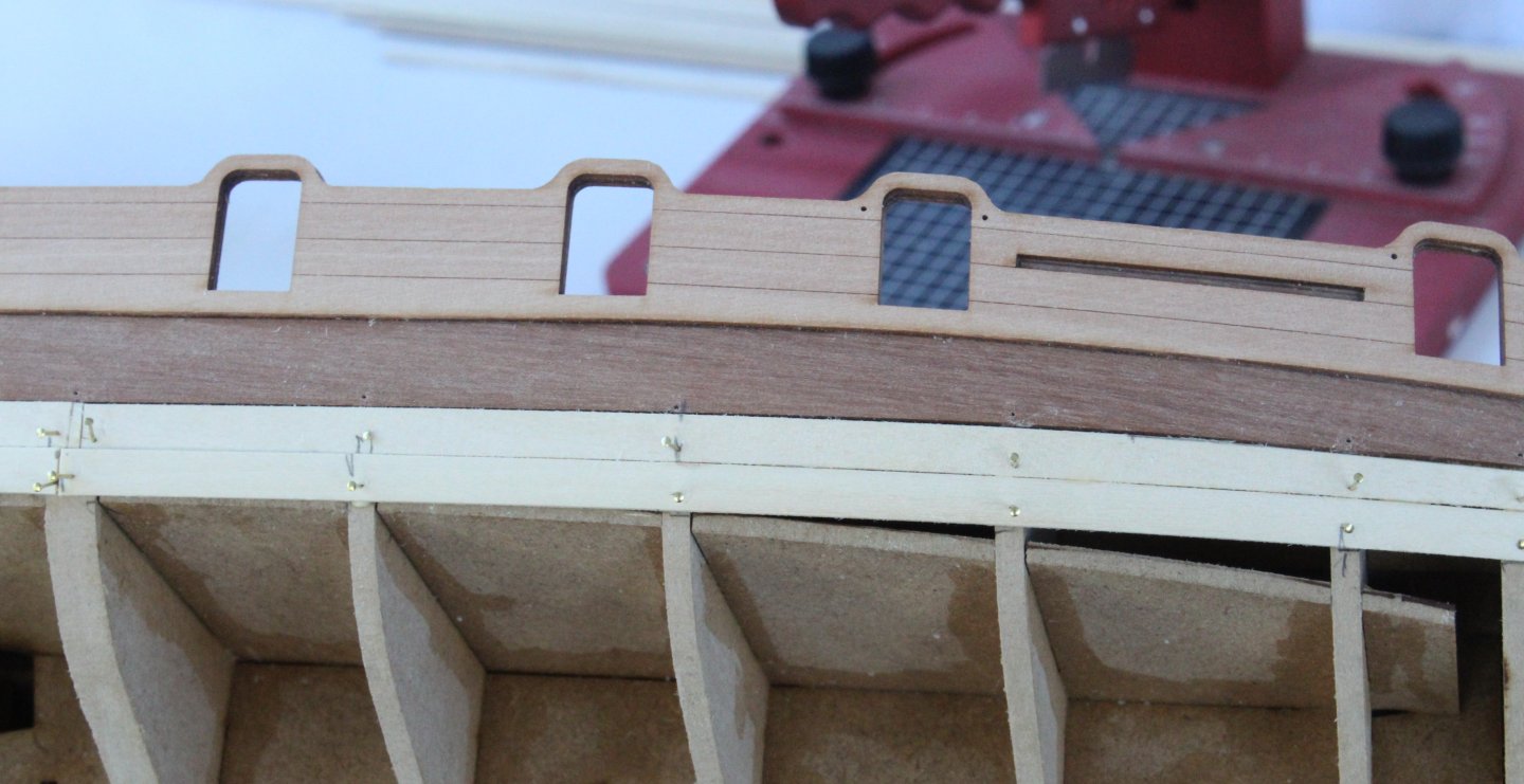
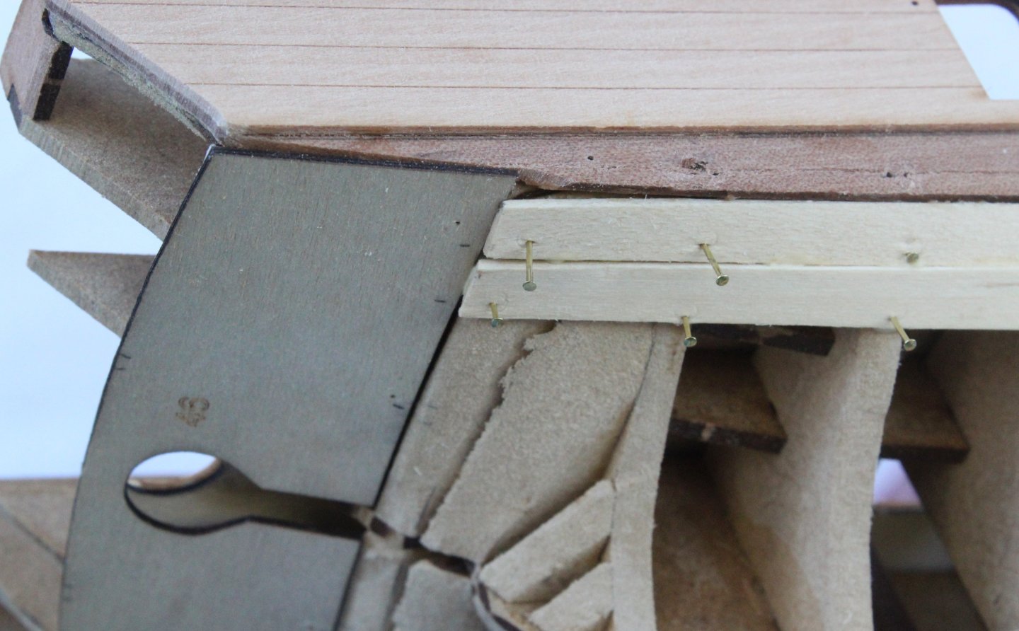
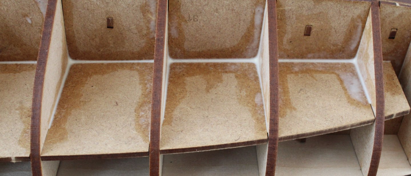
I have now made a start of adding the first planking layer. For the first few downward strakes I will use the double bulkhead as a join so I can add a bow facing and stern facing strake separately. This makes shaping the bow and stern termination much easier. In the photo below I have prepared the first set of strakes for both sides noting I did taper the bow facing ones. The hull has been placed on a towel in readiness. Before the strakes were fitted I did bevel the top edge of the strake. In the following set of photos the first strake has been glued and pinned in place. I am really please with how this looks. In the next set of photos the second strake has been added. I did bevel the top edge of the second strake to get a better, tighter fit. Next it was time to add the add the garboard strake. I positioned a plank and marked the start point where the plank needs to be trimmed to follow the curve. Using a scrap piece planking material I made a template for the bow curve. Using the template I transferred the bow shaping to the plank. Once the plank had been trimmed and I was happy with the fit the garboard plank was glued and pinned. I did slightly bevel the plank edge which butts up to the keel. I repeated the same process to add the garboard plank on the other side.


-
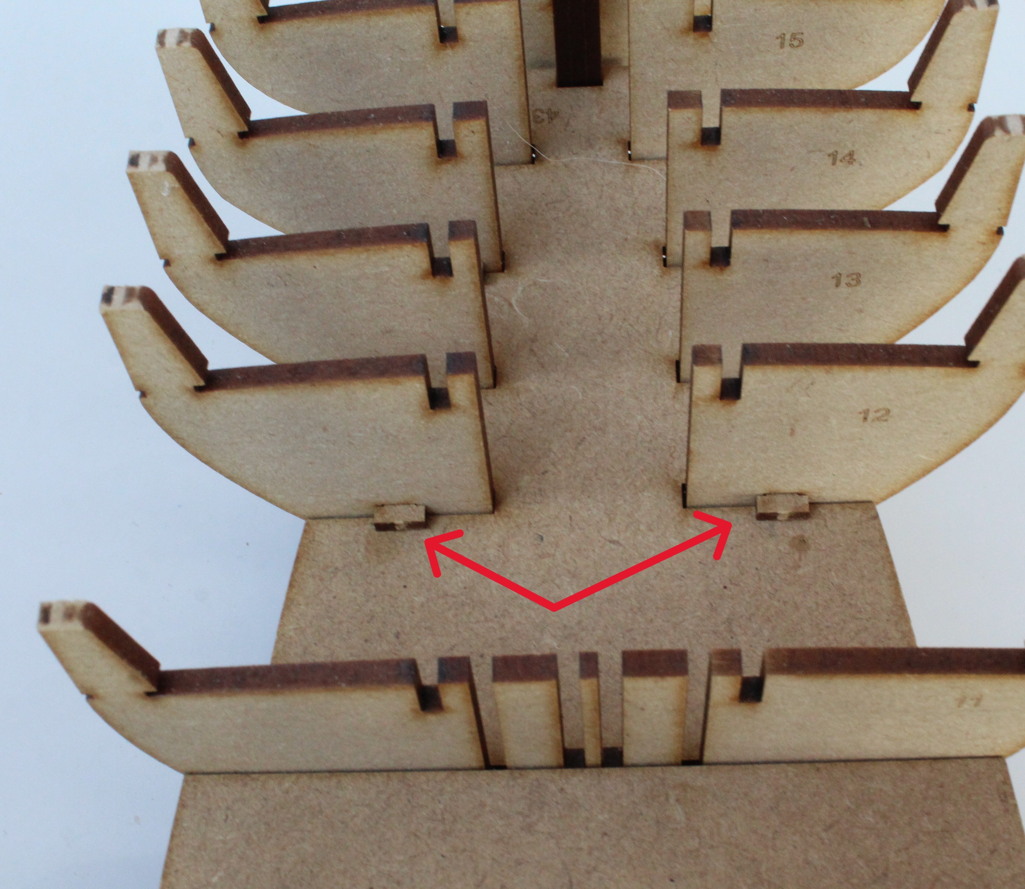
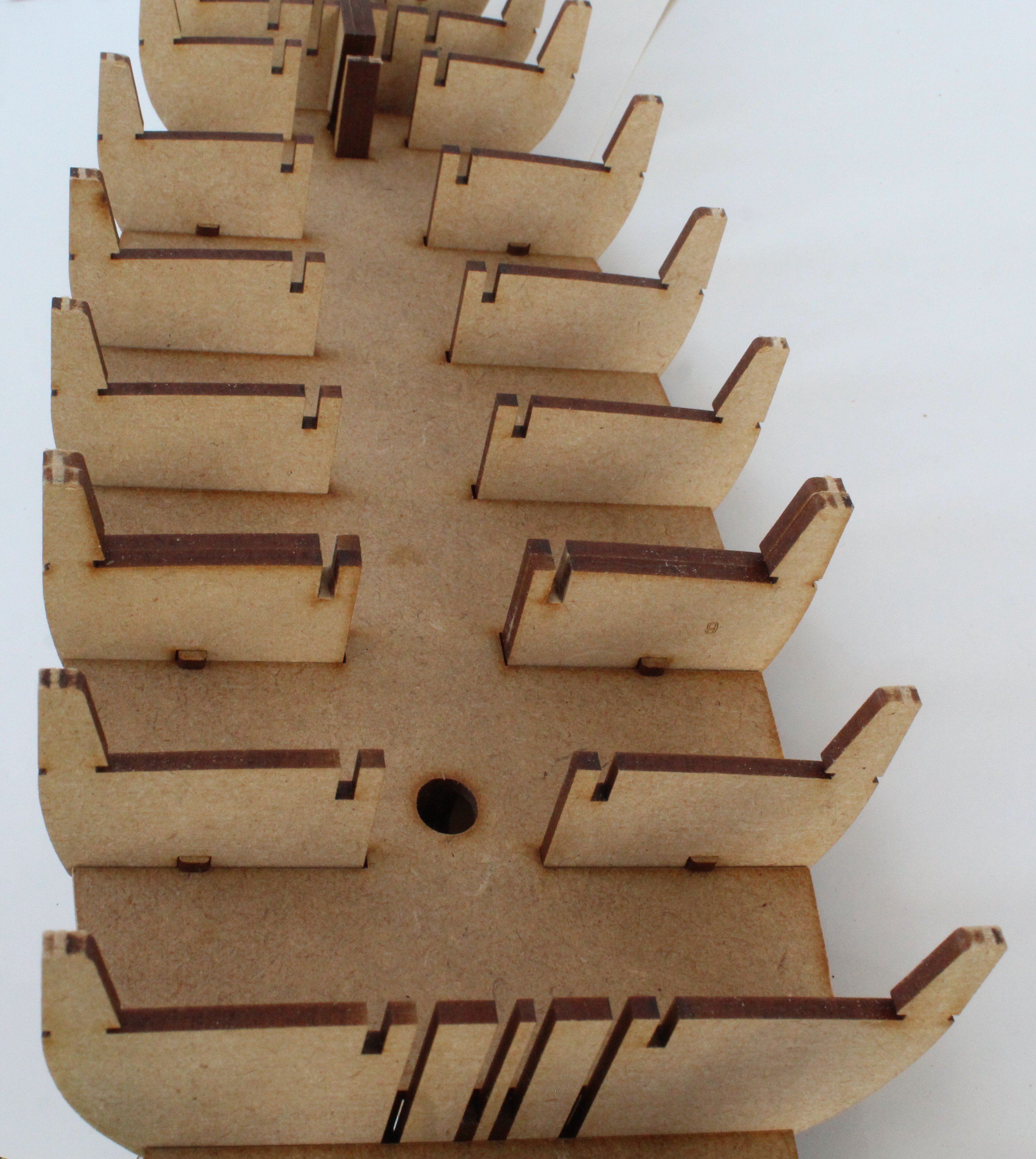
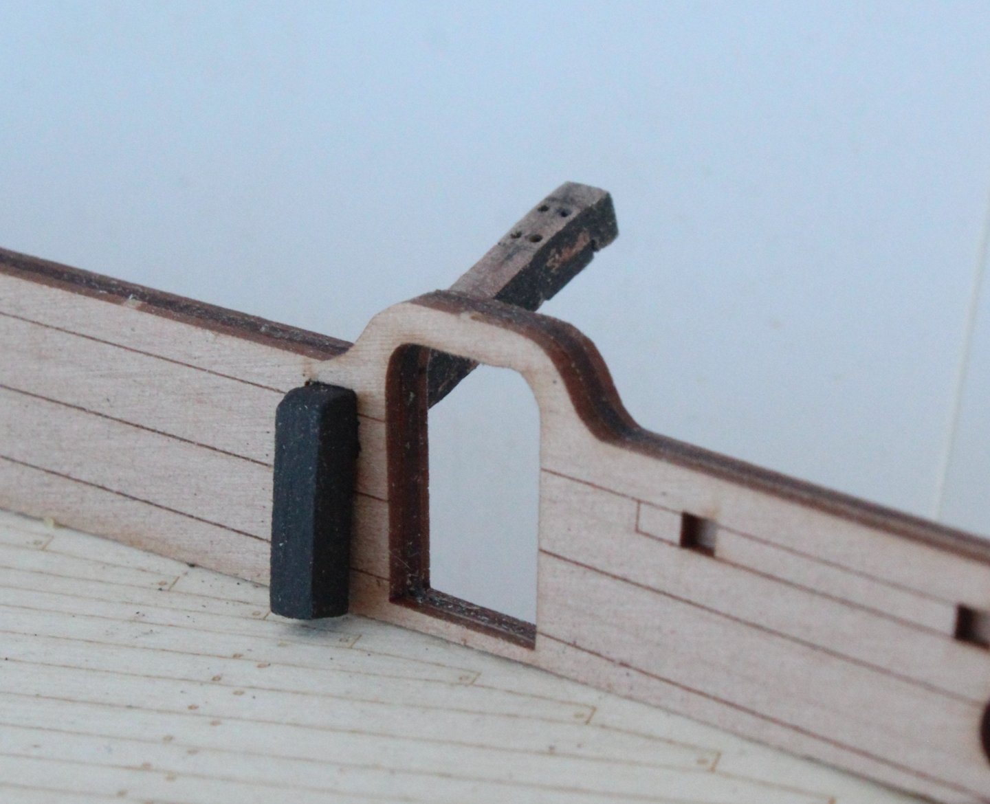
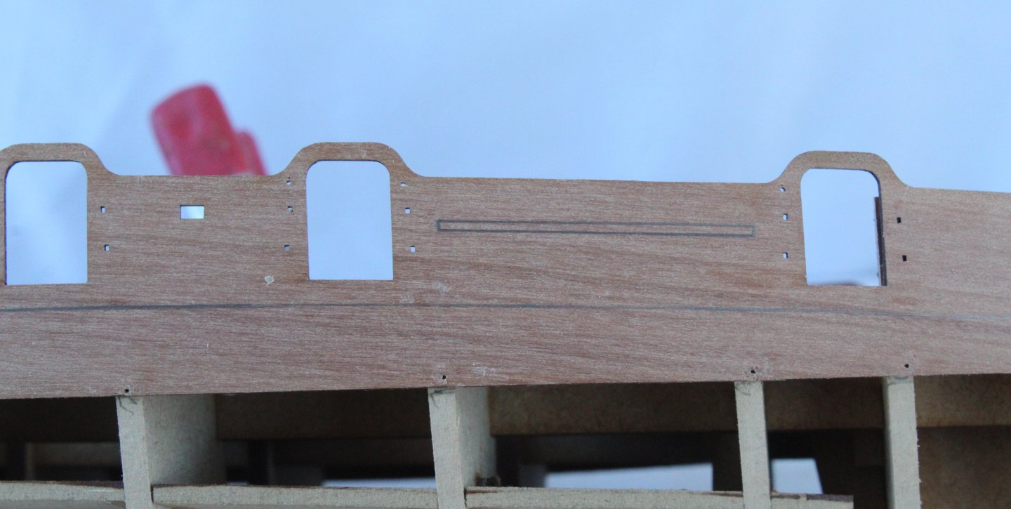
Following on from my last post the inner bulwark patterns, after a little bit of fettling, were glued them in place and then clamped. As can be seen in the following set of photos I did use the pin locating hole to ensure they were correctly positioned. The next set of photos were taken after all the clamps were removed. I felt this would now be a good time to test fit the catheads and thankfully they both slotted in without too much effort. I add a bit wood to the bottom edge so they actually sits on the deck. After removing the excess timber from the stern section of the bulwarks the inner stern counter pattern was fitted and the hull is now ready for the next phase of the build which will be to add the first layer of planking. At the widest point the hull will require 15 planks, and as indicated in the build manual, the first plank will need to be tapered to fit around the bow section. I plan fit each strake as two planks using the double width bulkhead 9 for the join.


-
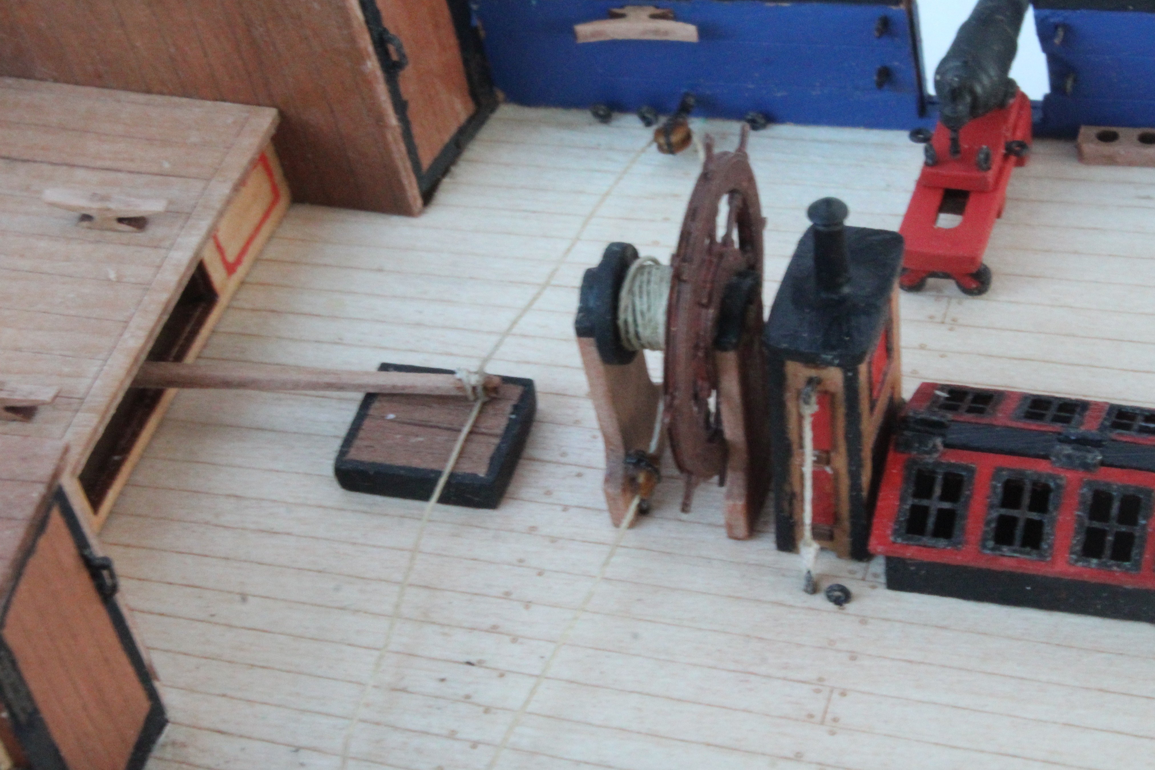
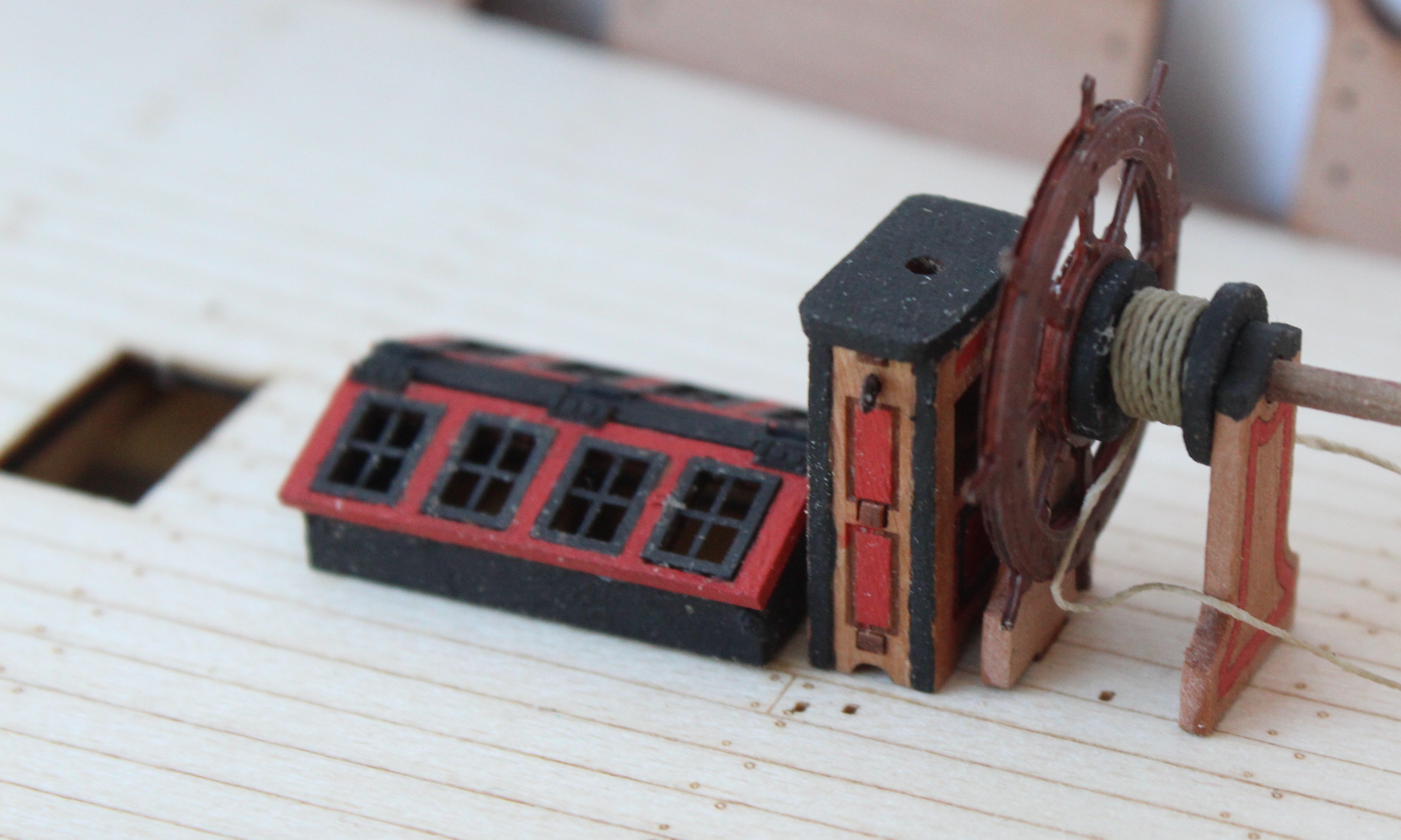
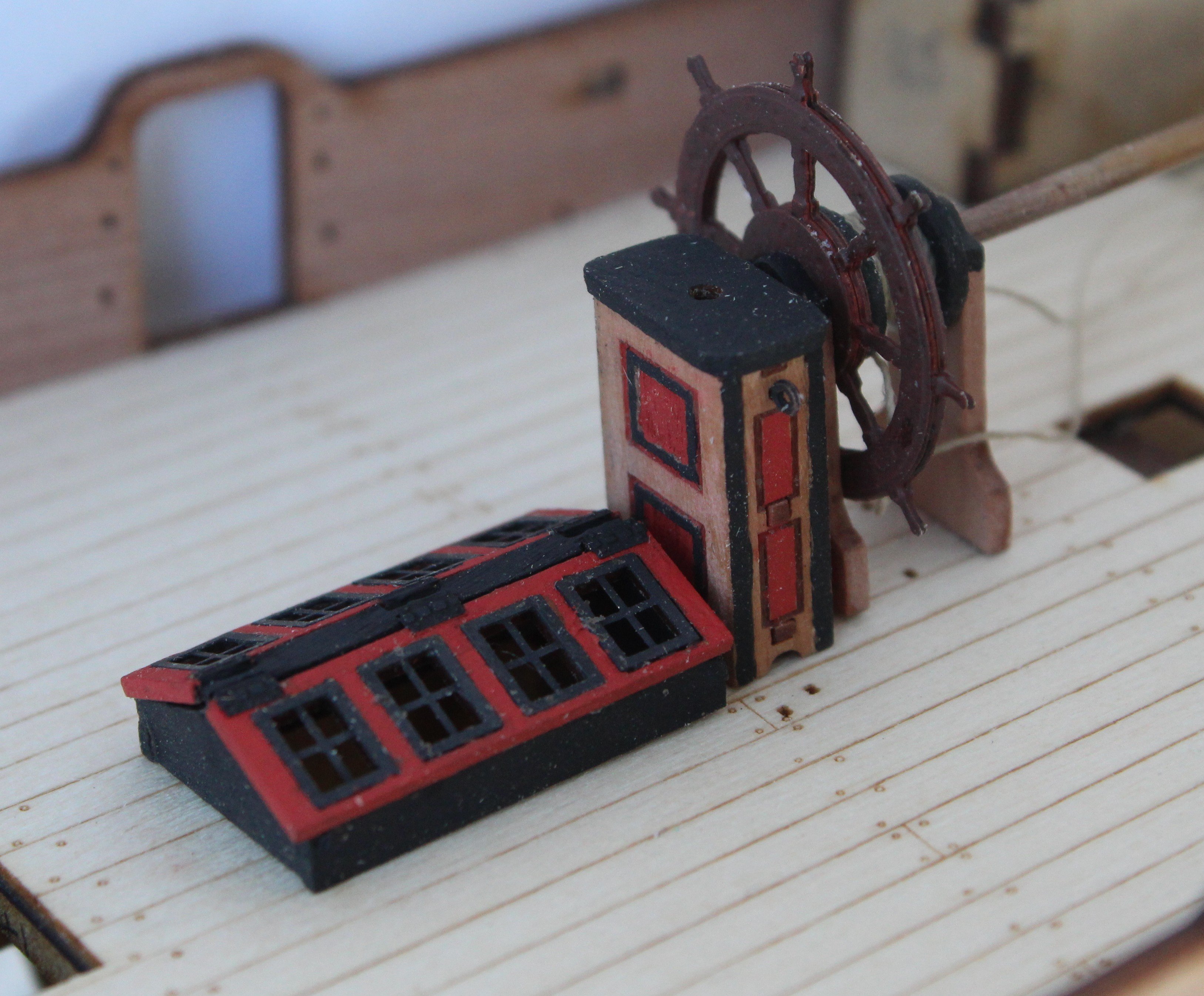
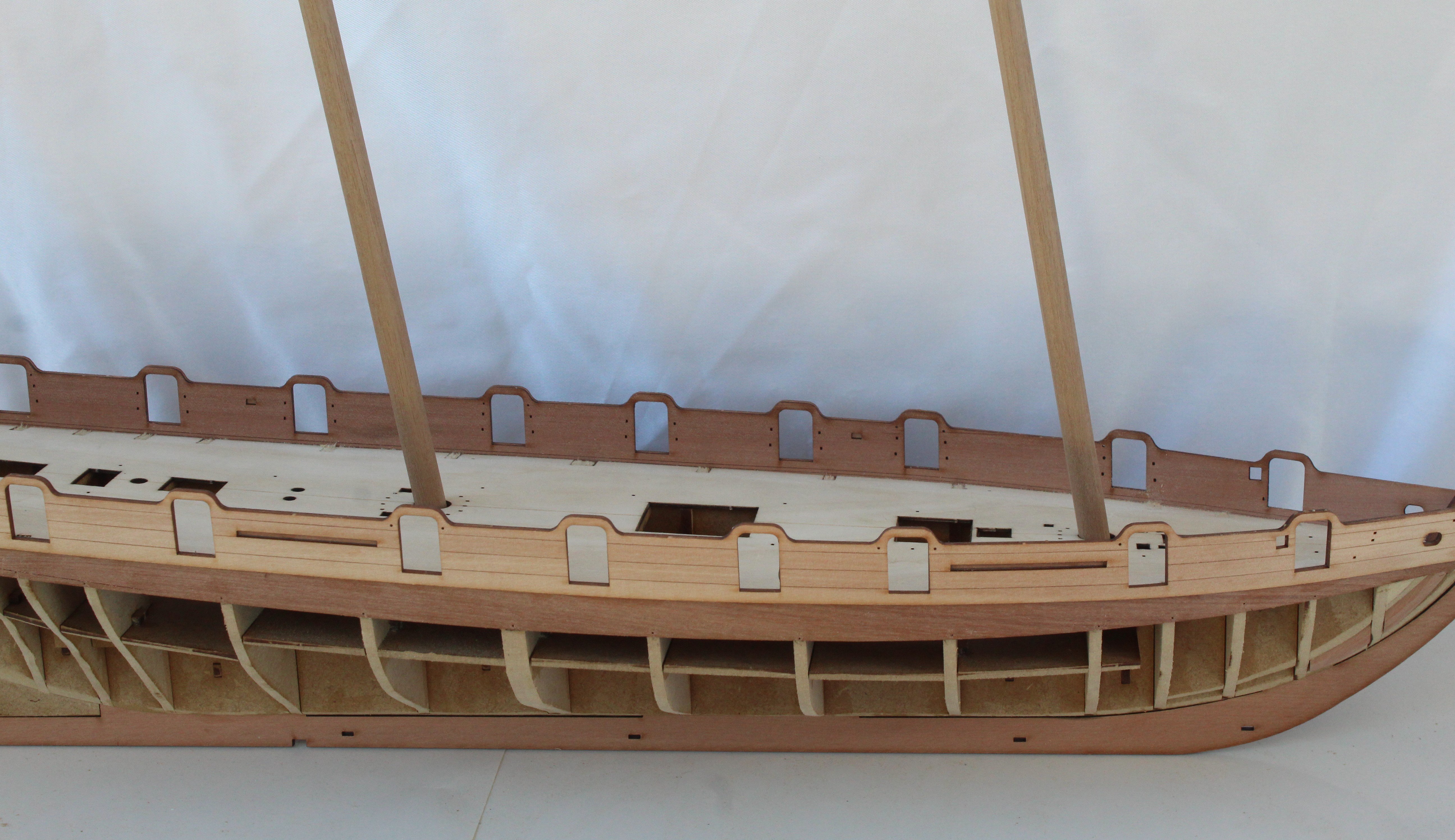
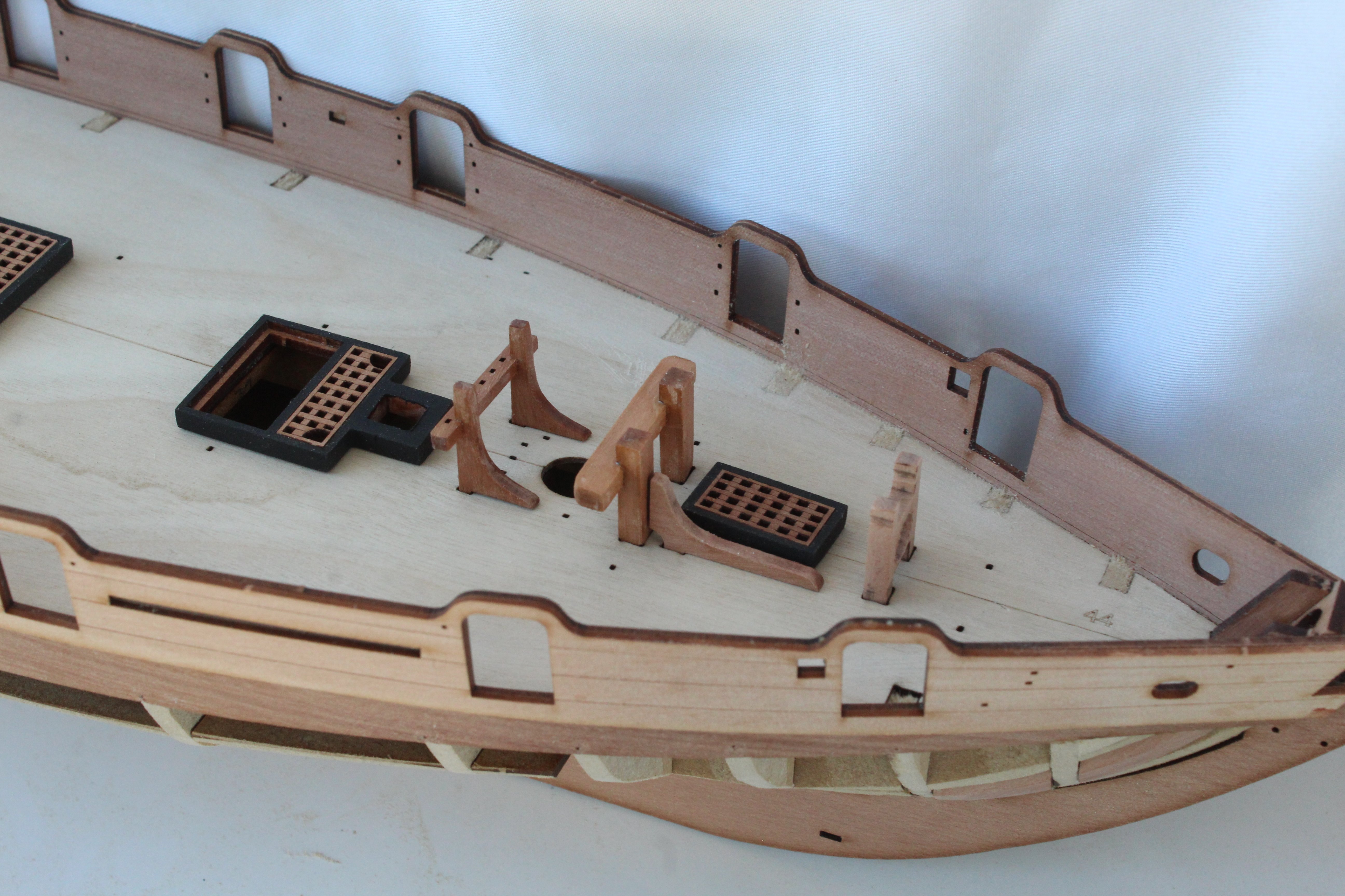
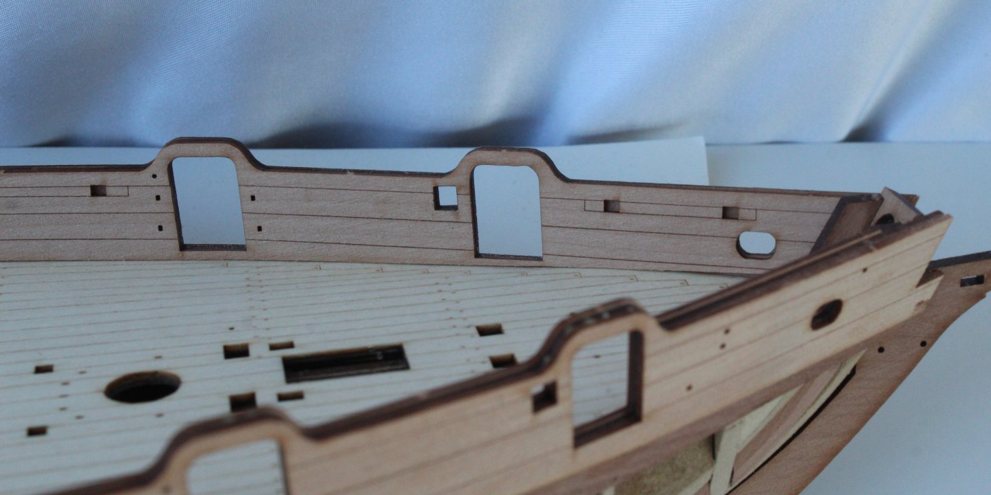
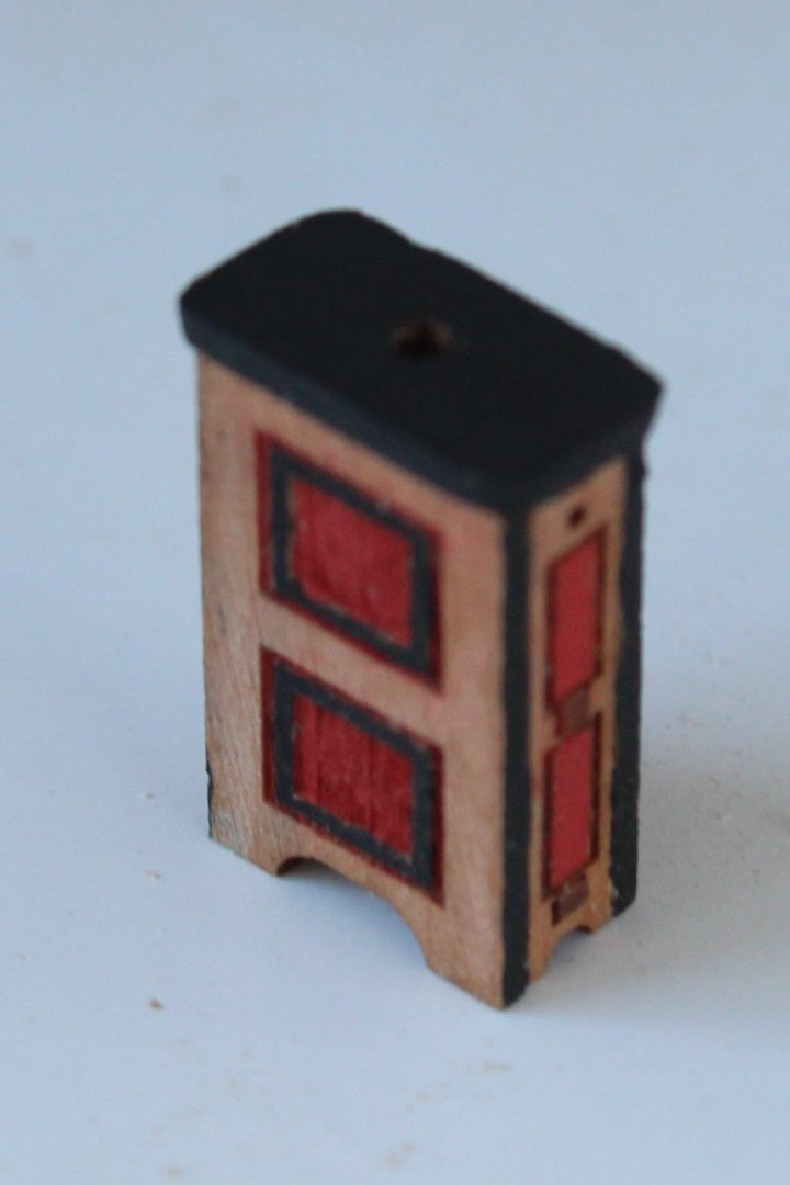
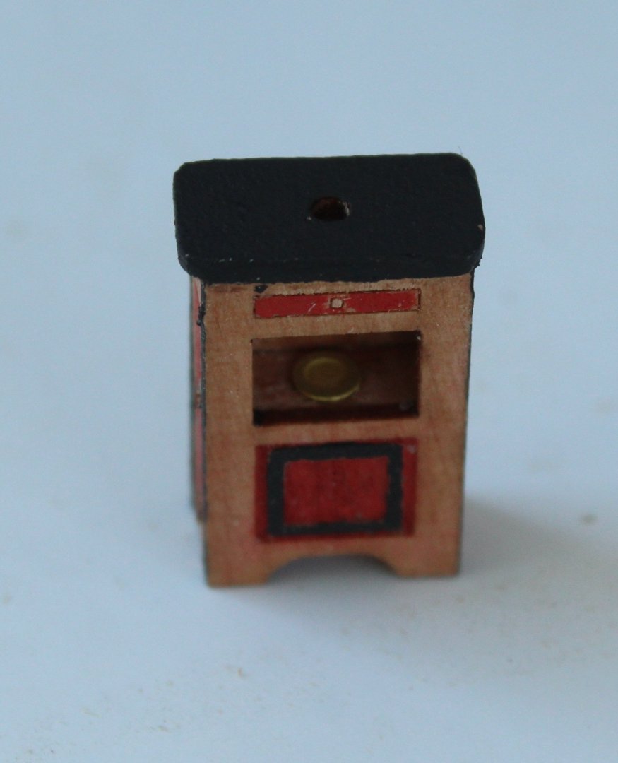
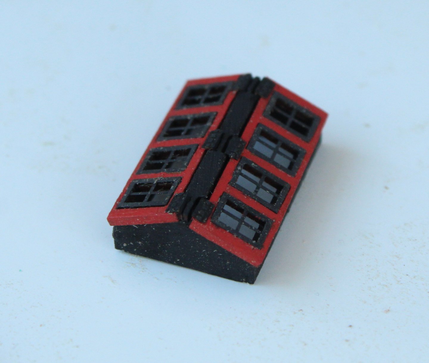
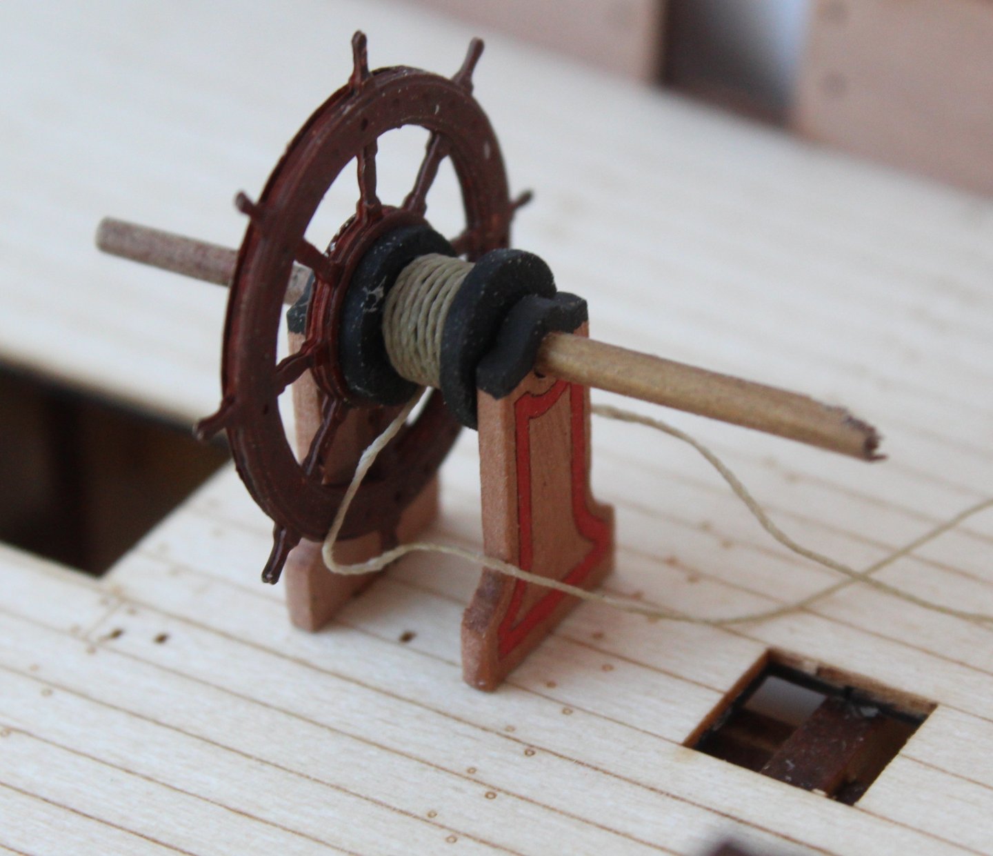
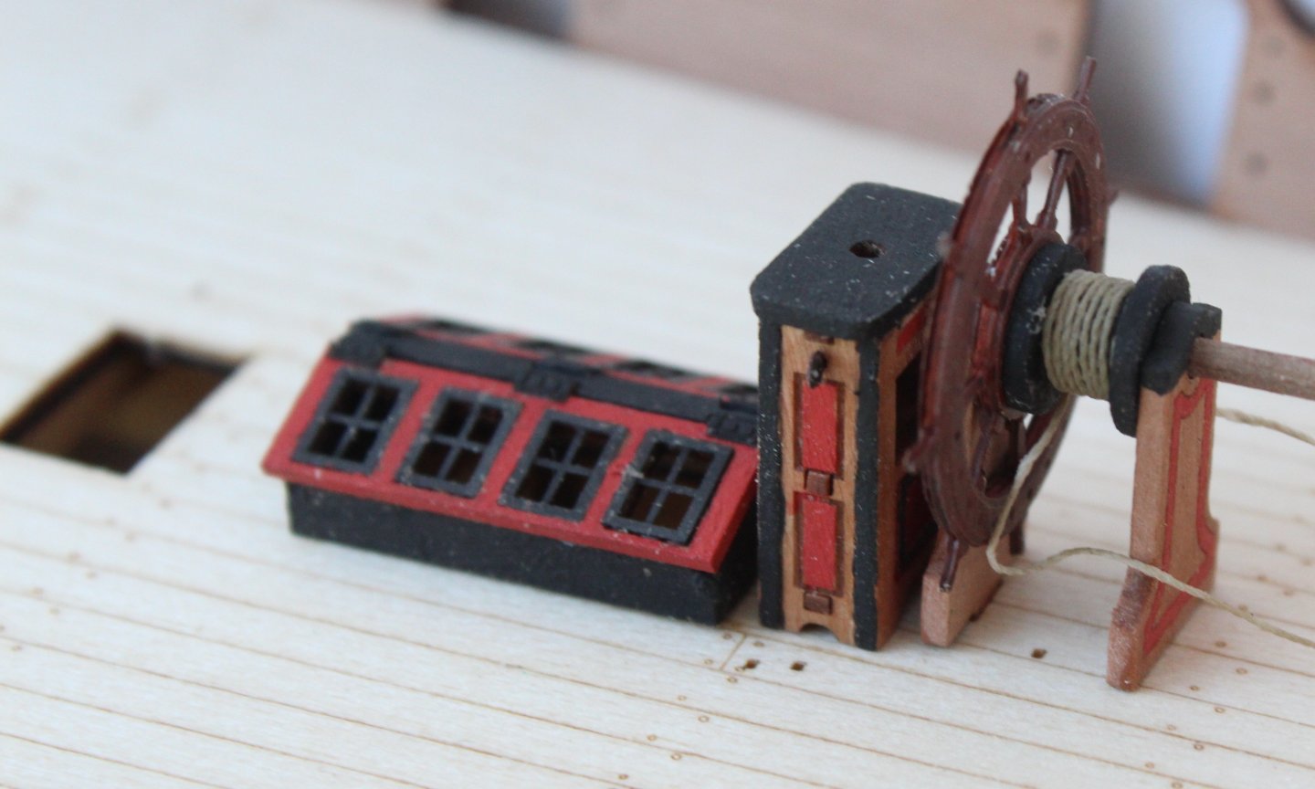
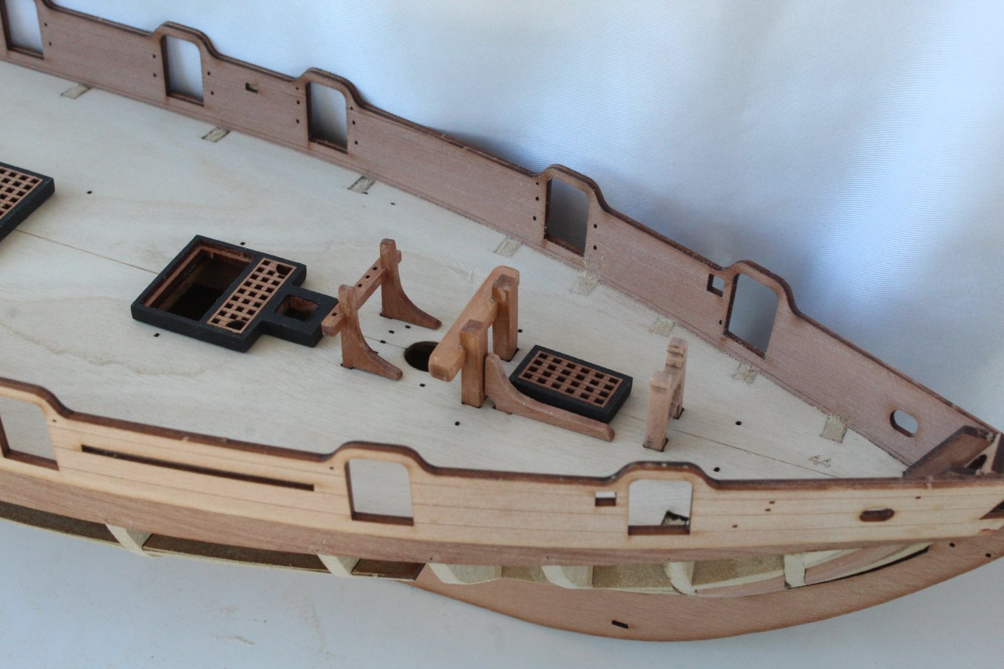
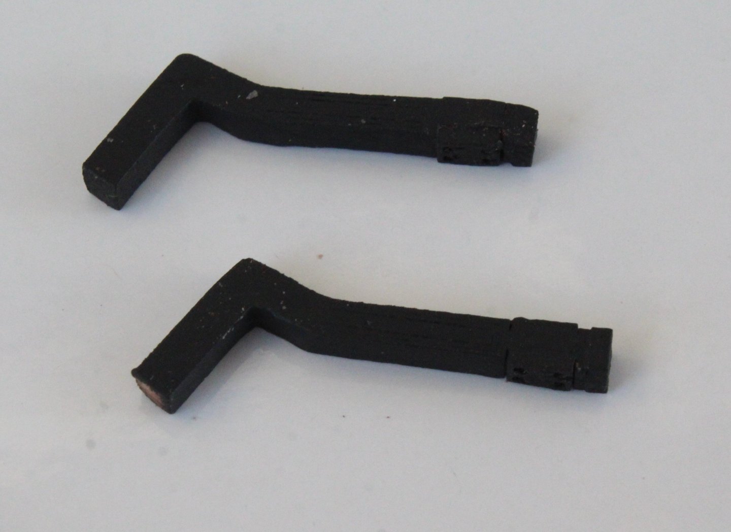
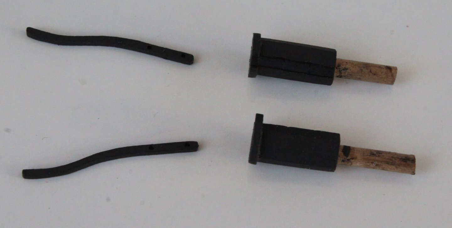
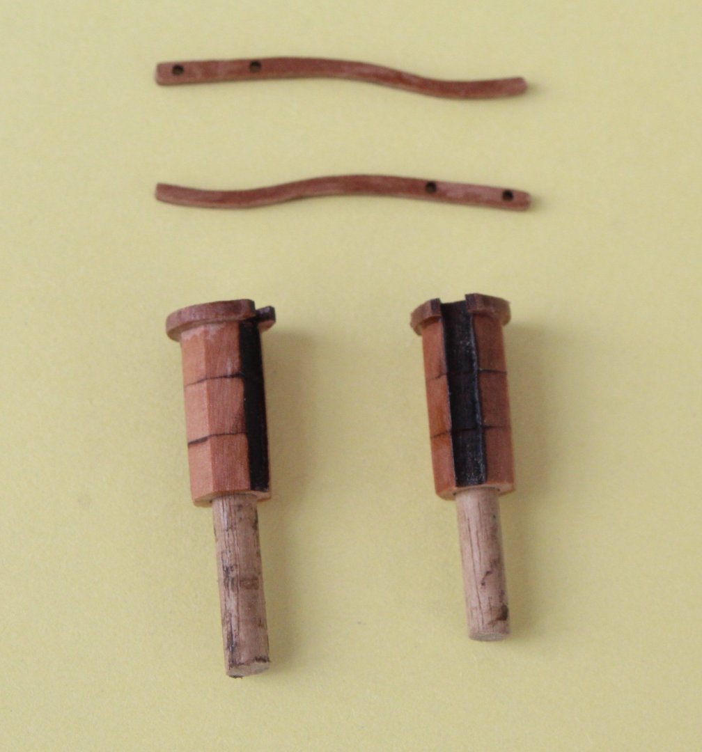
The laser etch deck has now been glued in place. I applied a layer of glue to the central section of the base deck as the outer edges will be held in place when the inner bulwark patters are added. Whilst waiting for the glue to dry I did a bit more work on some of the deck items. I have opted for a paint finish of the binnacle as shown in the photos below. Next I completed the assembly of the skylight. I decided the base frame would look good painted black with the skylight window frames painted red with black window frames. Having abandoning using the syren wheel for this project I have painted the wheel and ships wheels frames. I have also added the thread to the wheel drum. I did a trial test fit on deck. The ships drum does need to be rotated when it is finally installed so the two thread ends are correctly positioned for the rigging blocks. Next I added the binnacle and skylight to the deck (dry fit only) More deck items were test fitted, which confirmed that the laser etched deck was perfectly aligned with the base deck beneath as I did not have to do any work when inserting the various items into their respective locating holes. Finally I set about fitting the inner bulwark patterns which is still WIP. I trimmed the front and rear edges of both patterns and then they were test fitted, using pins to ensure the gun ports were all correctly aligned. As can been seen in the photo below the bottom edge of the port pattern will need trimming at the bow end as it is sitting proud. It was a completely different story with regards to the starboard pattern which was a great fit at the bow end but the final stern section was sitting proud, as shown below. There is no movement in the deck to push down any further so I will have to trim the bottom edge.


-
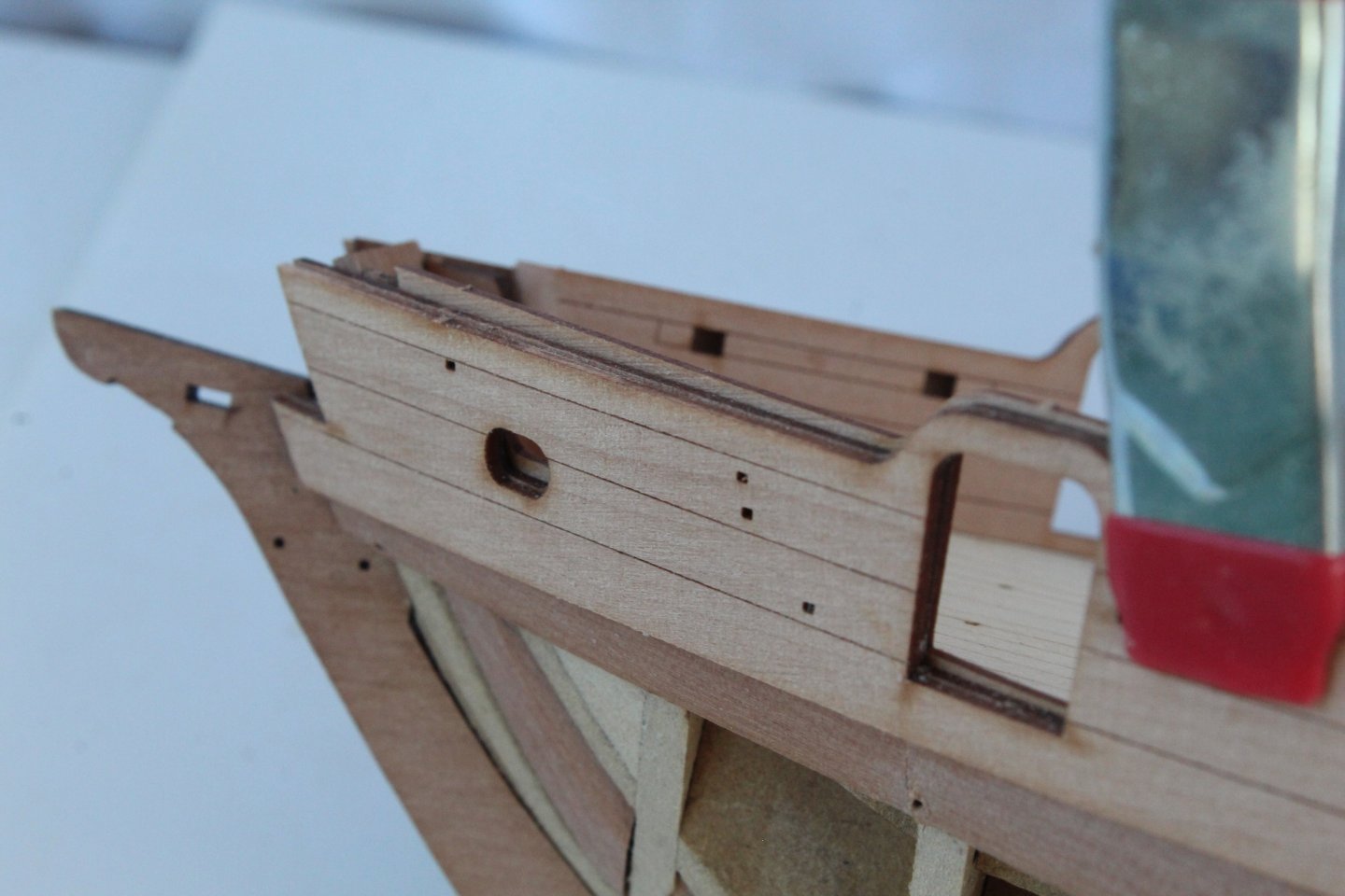
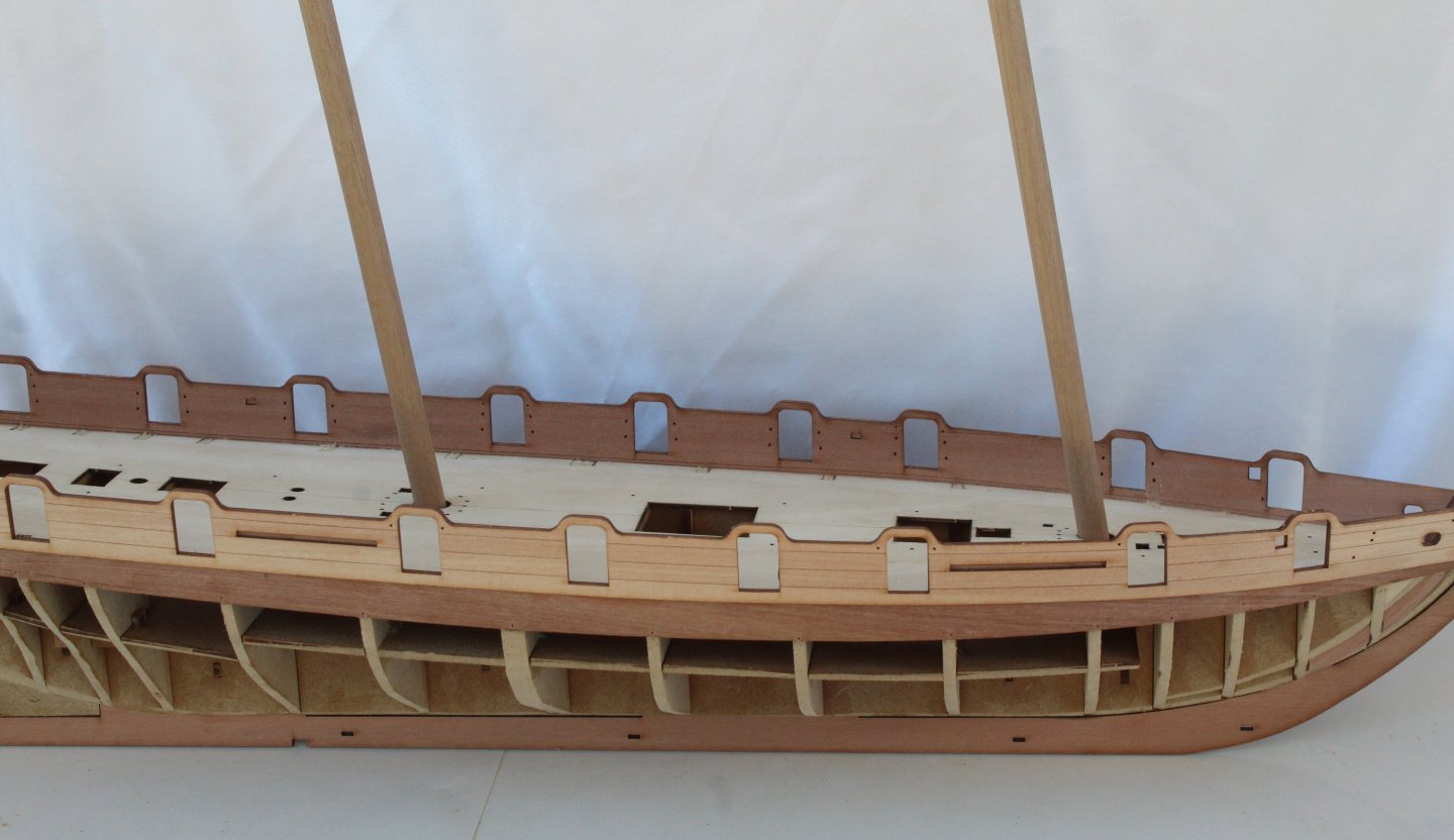
Over the last three days I have been working on the hull. The first task was to fair the hull. I took my time and, fingers crossed, I have done a reasonable job. It appeared to look OK when I checked it with some test planks. Next the outer bulwarks were fitted. I did experiment with scoring and bending the lower rear section with some test pieces and in the end I opted to use the scored method, as per the prototype. I also used the outer pattern of the rear cabin to help with the alignment. Next the outer pattern was clamped in place and so its lower position and channel positions could be marked in readiness for gluing in place. Pins were used to ensure the patterns were correctly aligned. The patterns were then glued in place. After the bulkhead ears were removed I decided to test fit the various deck items. The laser etched plywood deck was then fitted. It did require a little bit of sanding to get a good fit. The inner bulwark patterns were then test fitted but they require a little bit of work at either end before they can be fitted.


-
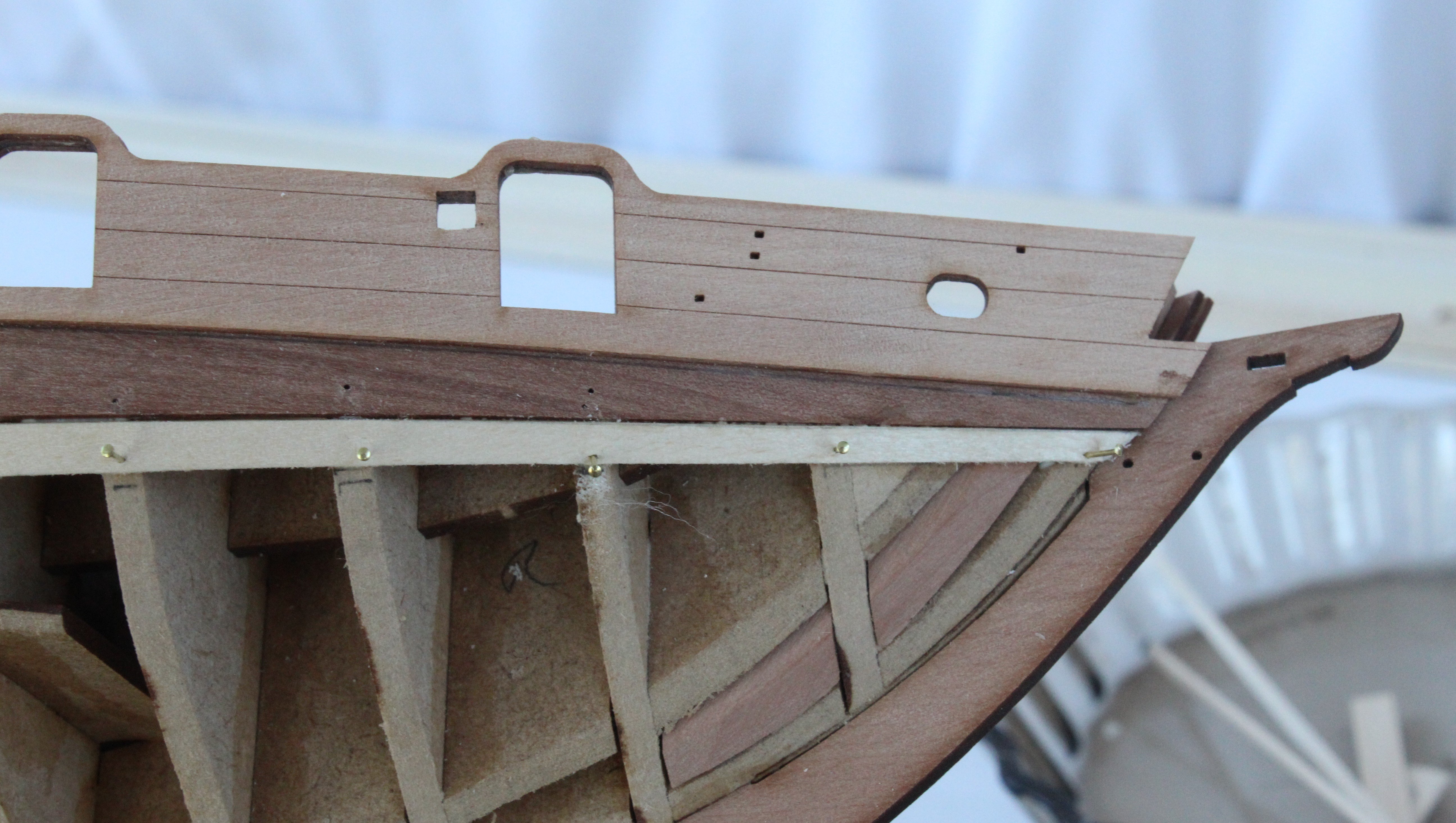
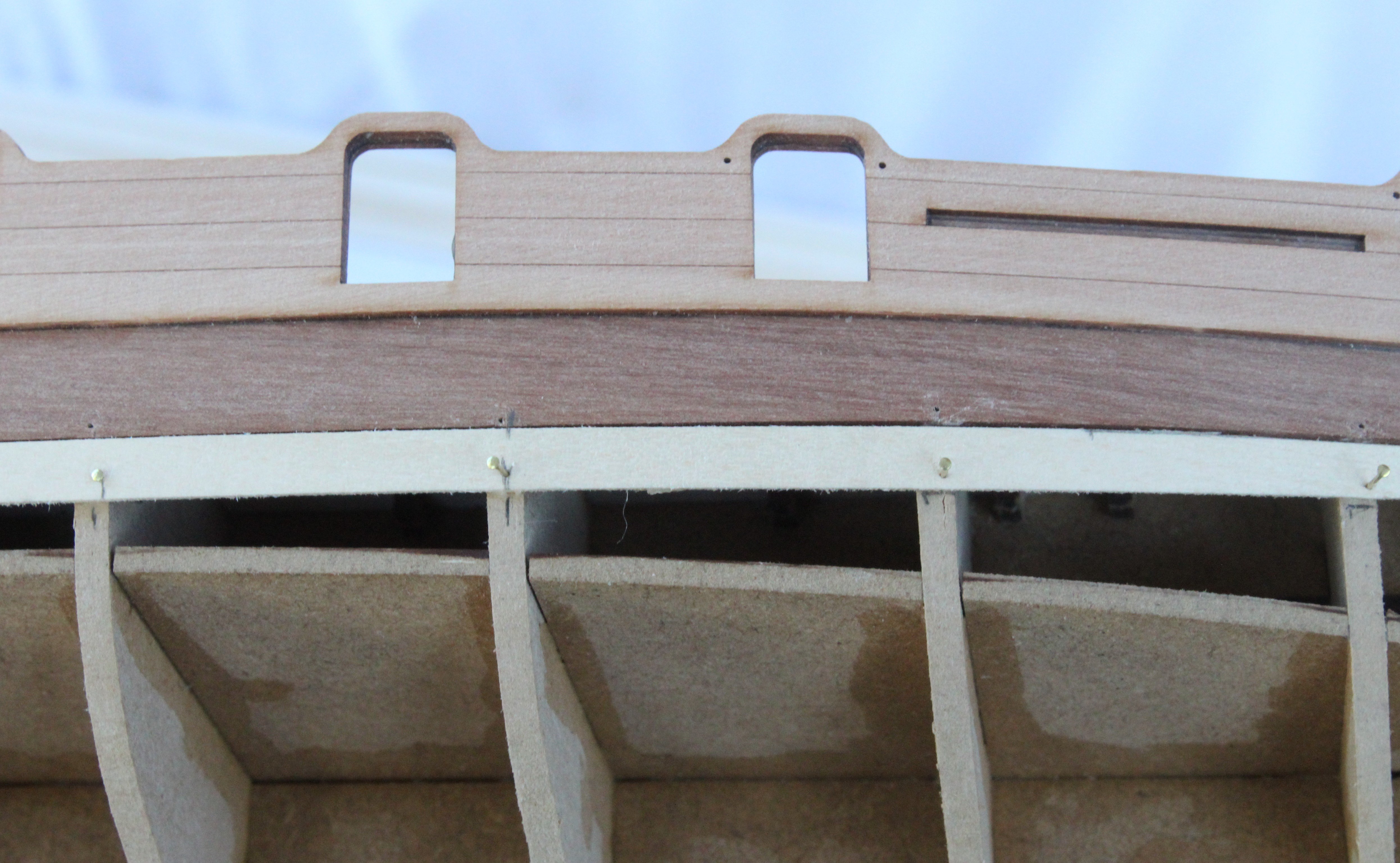
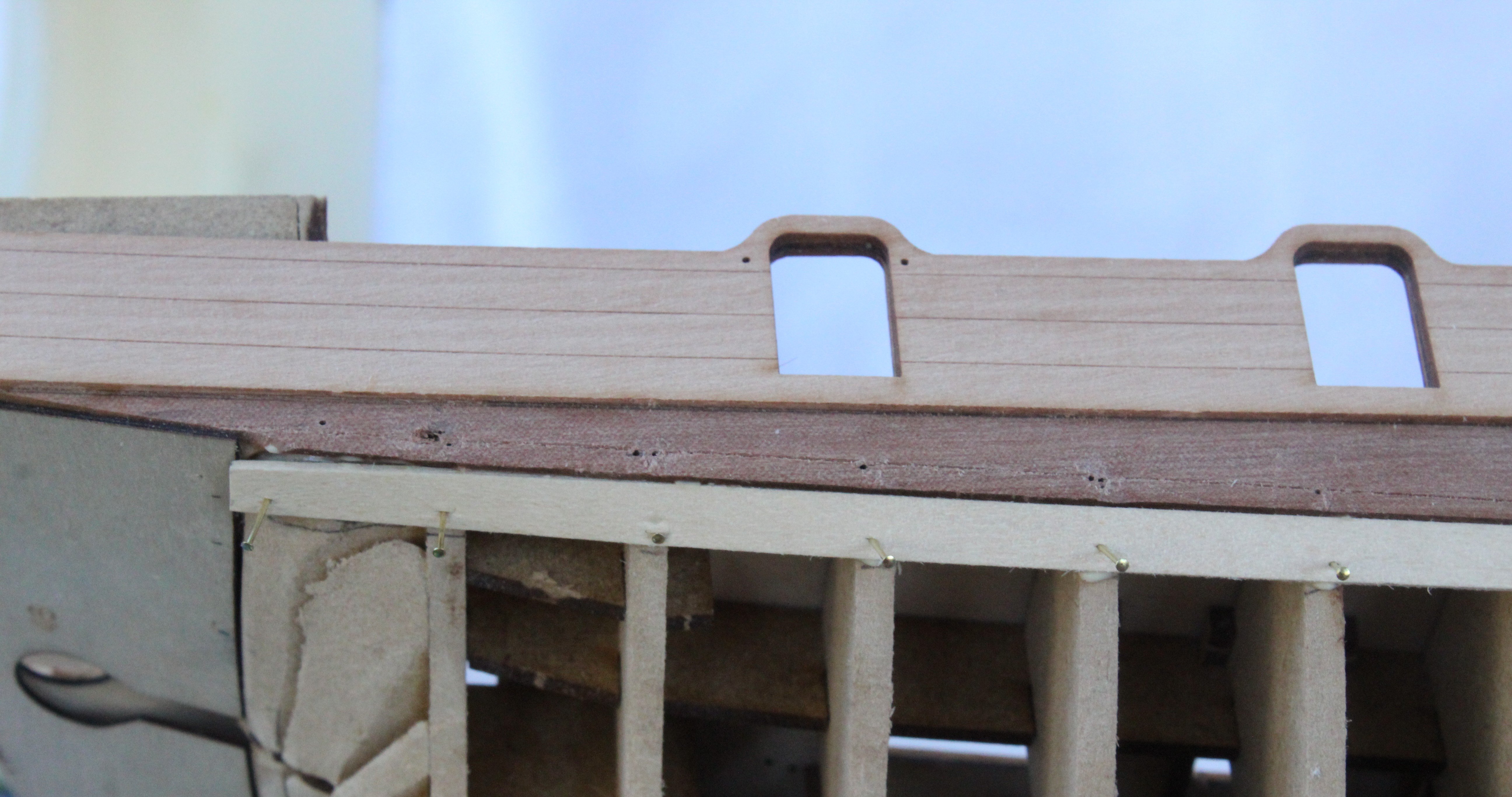
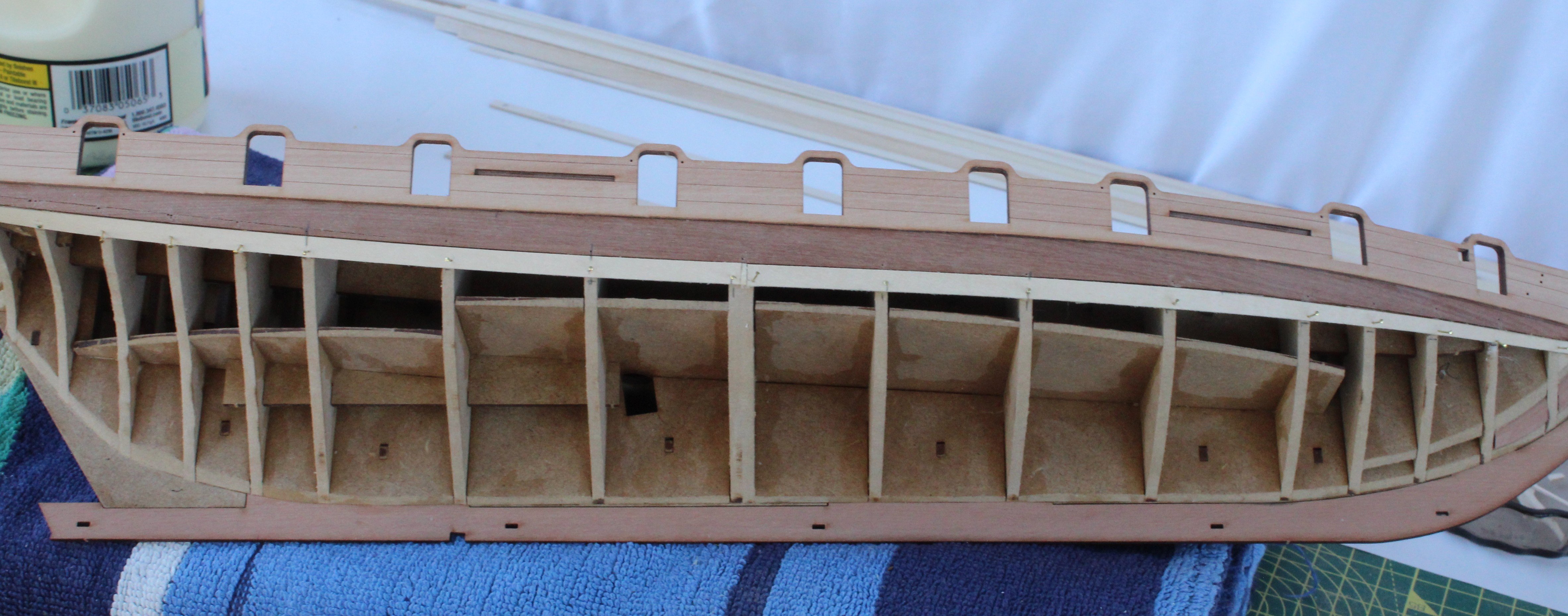
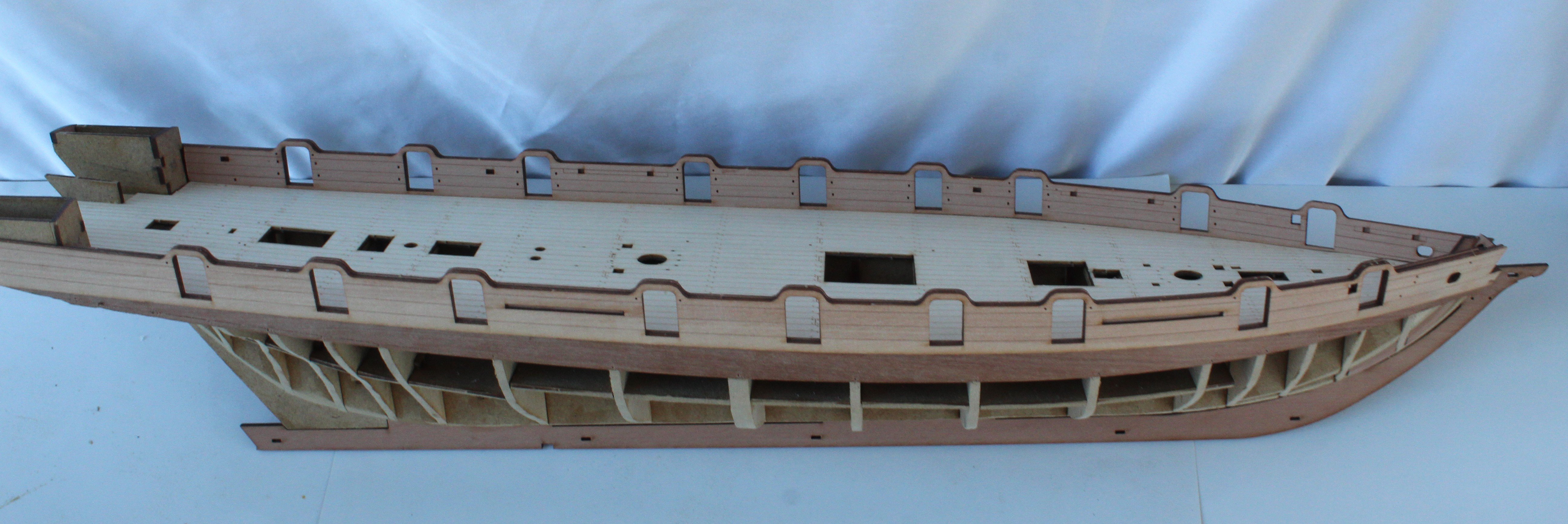
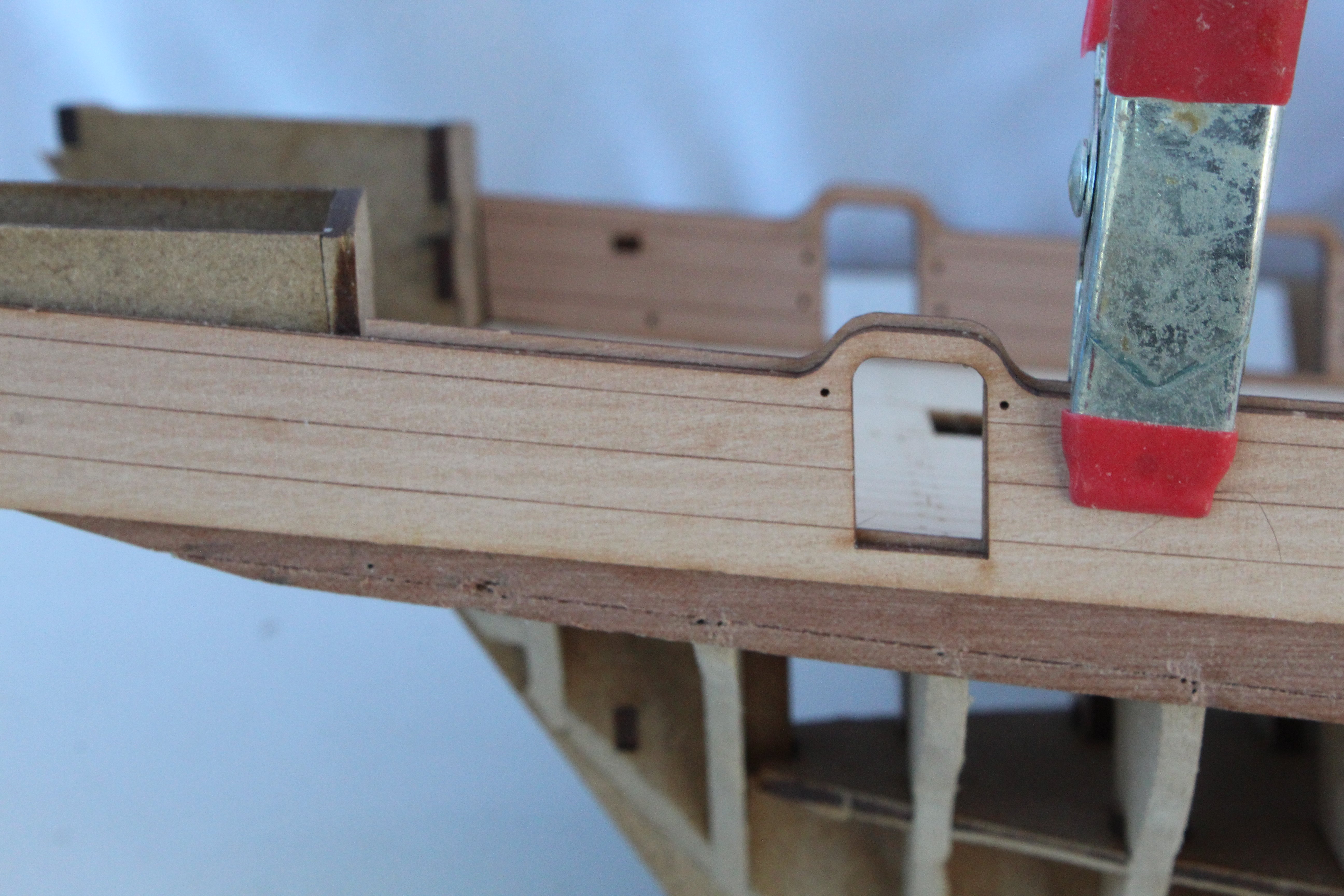
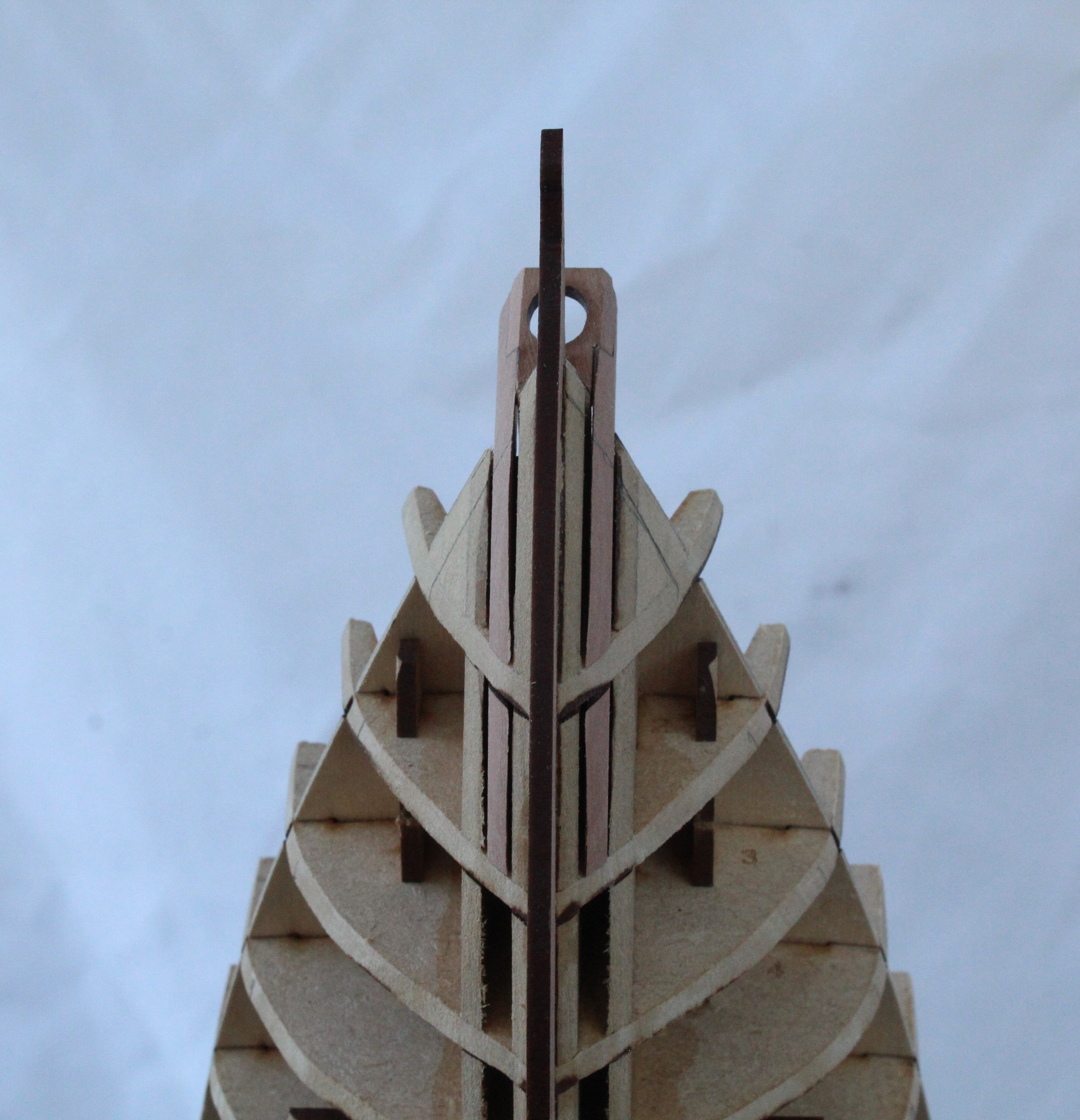
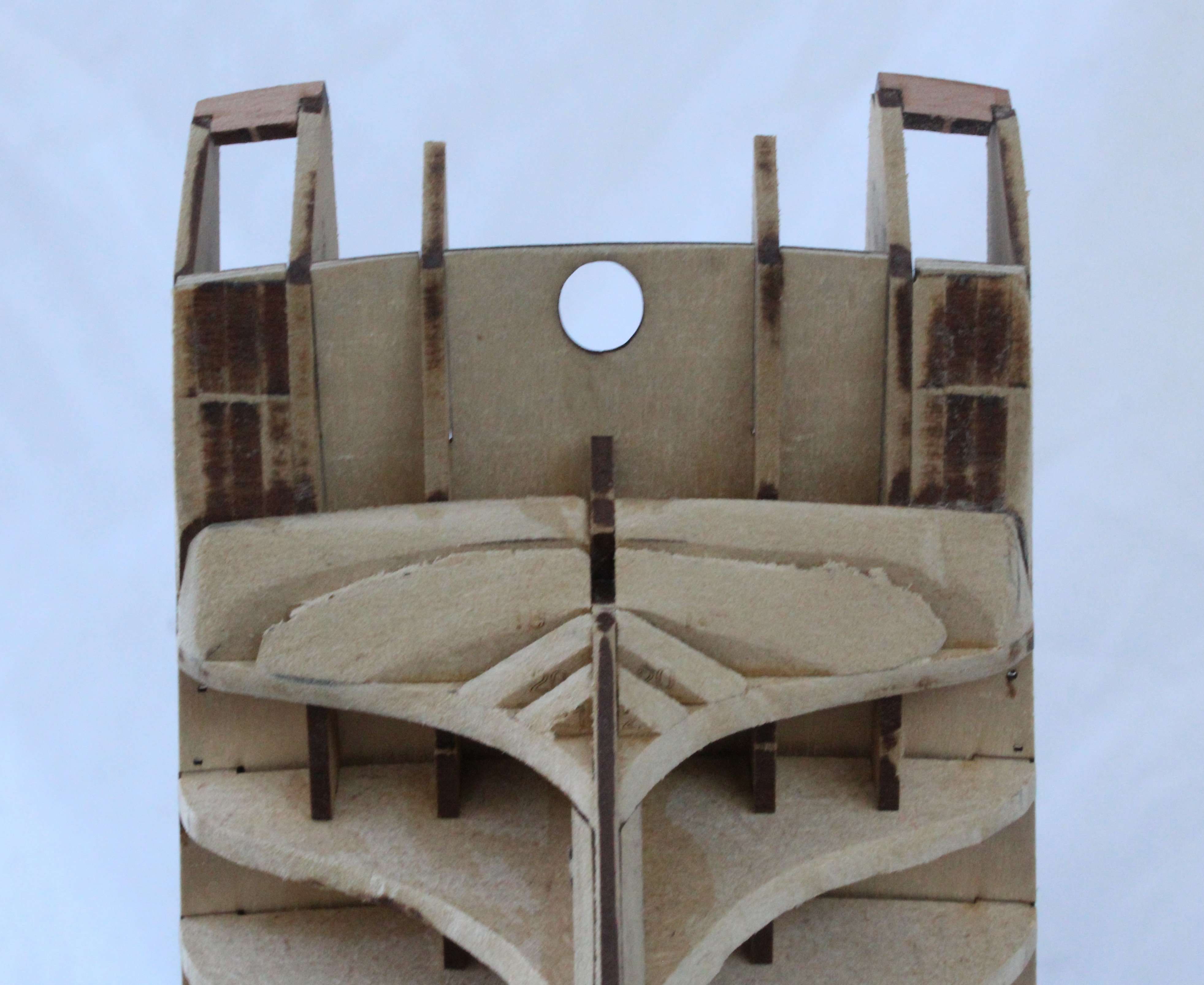
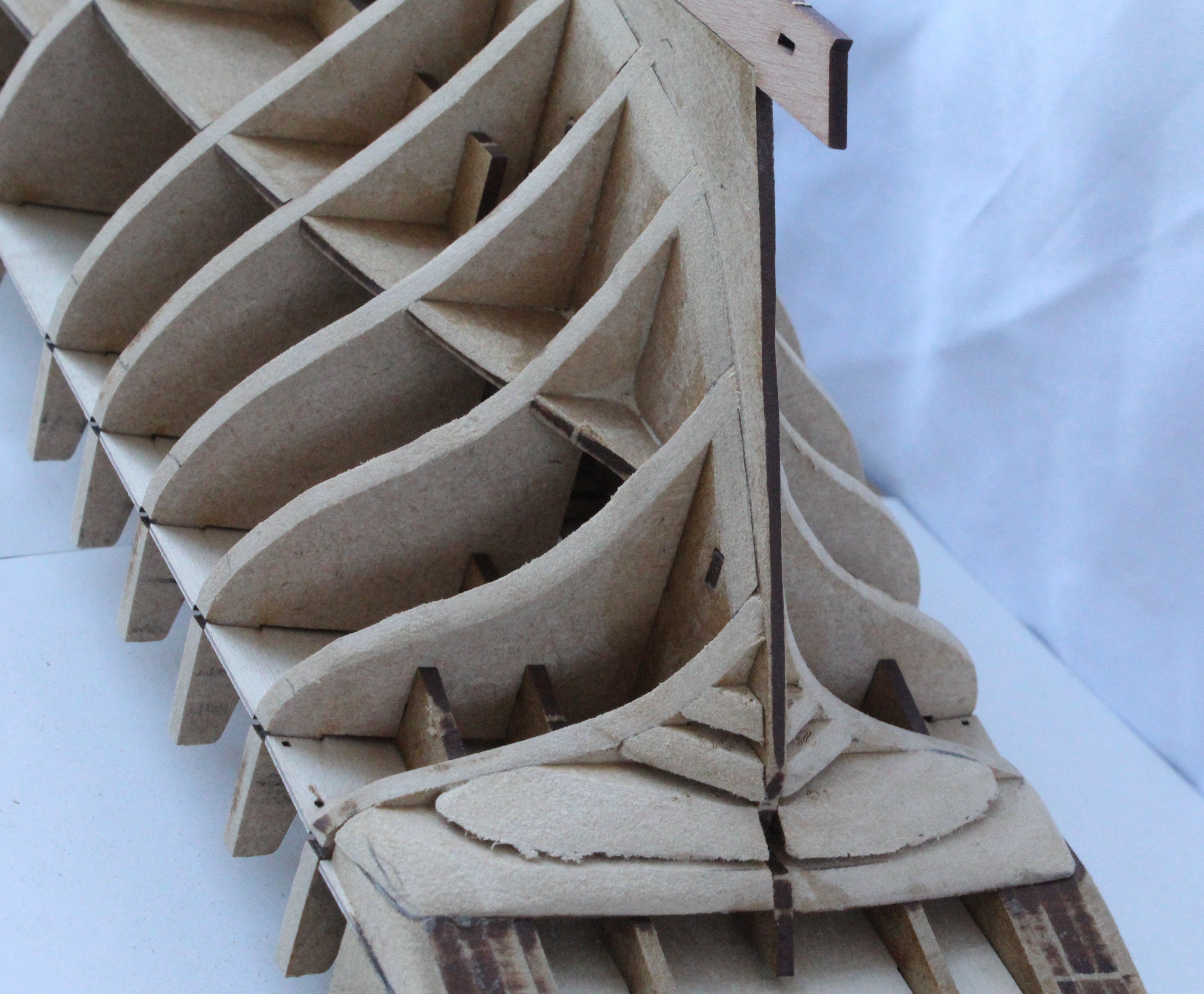
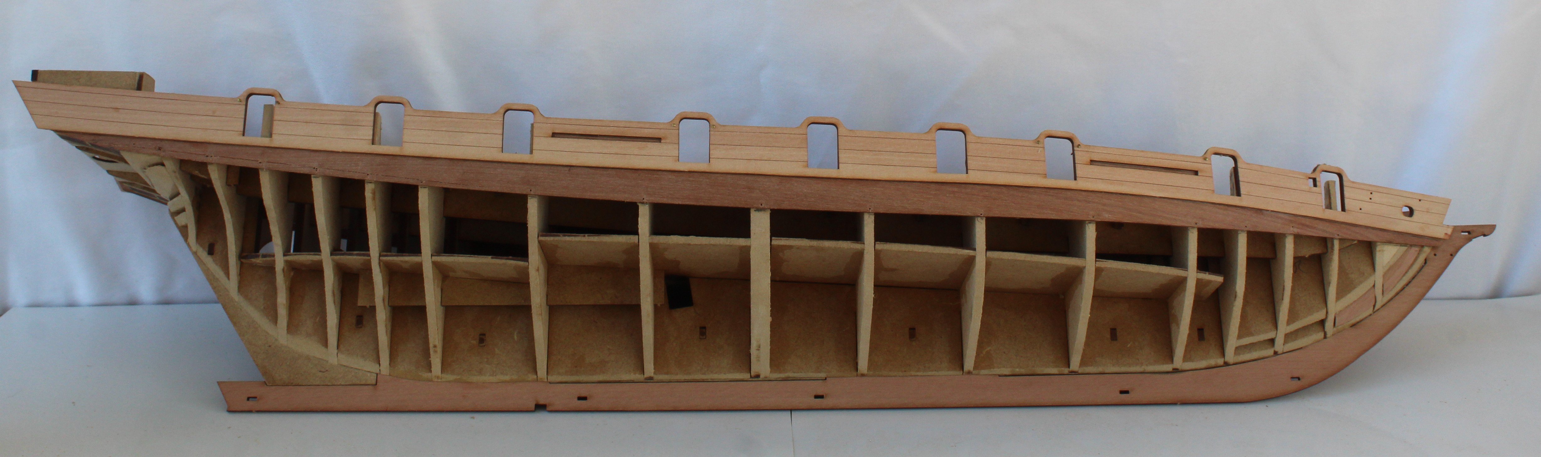
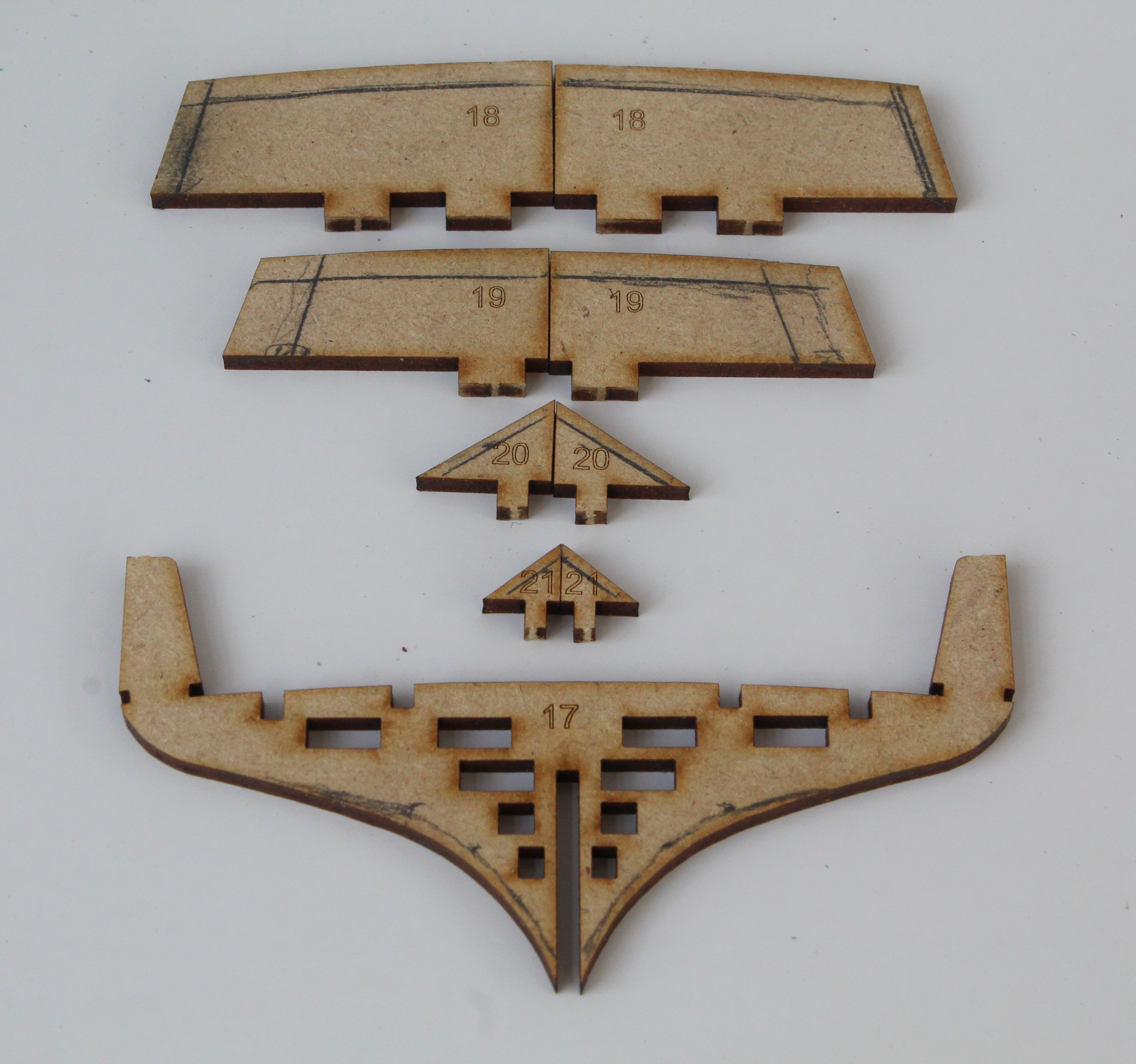
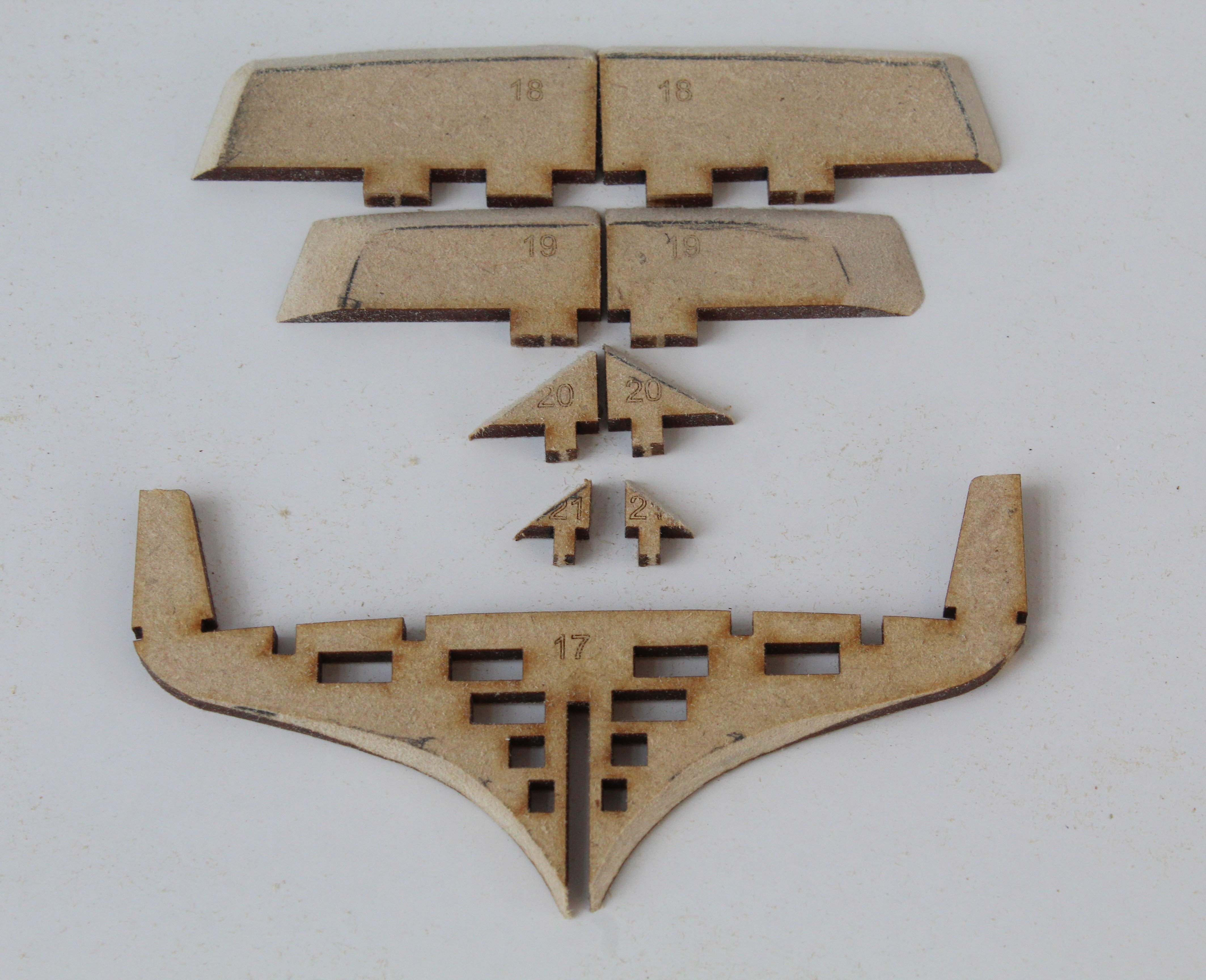
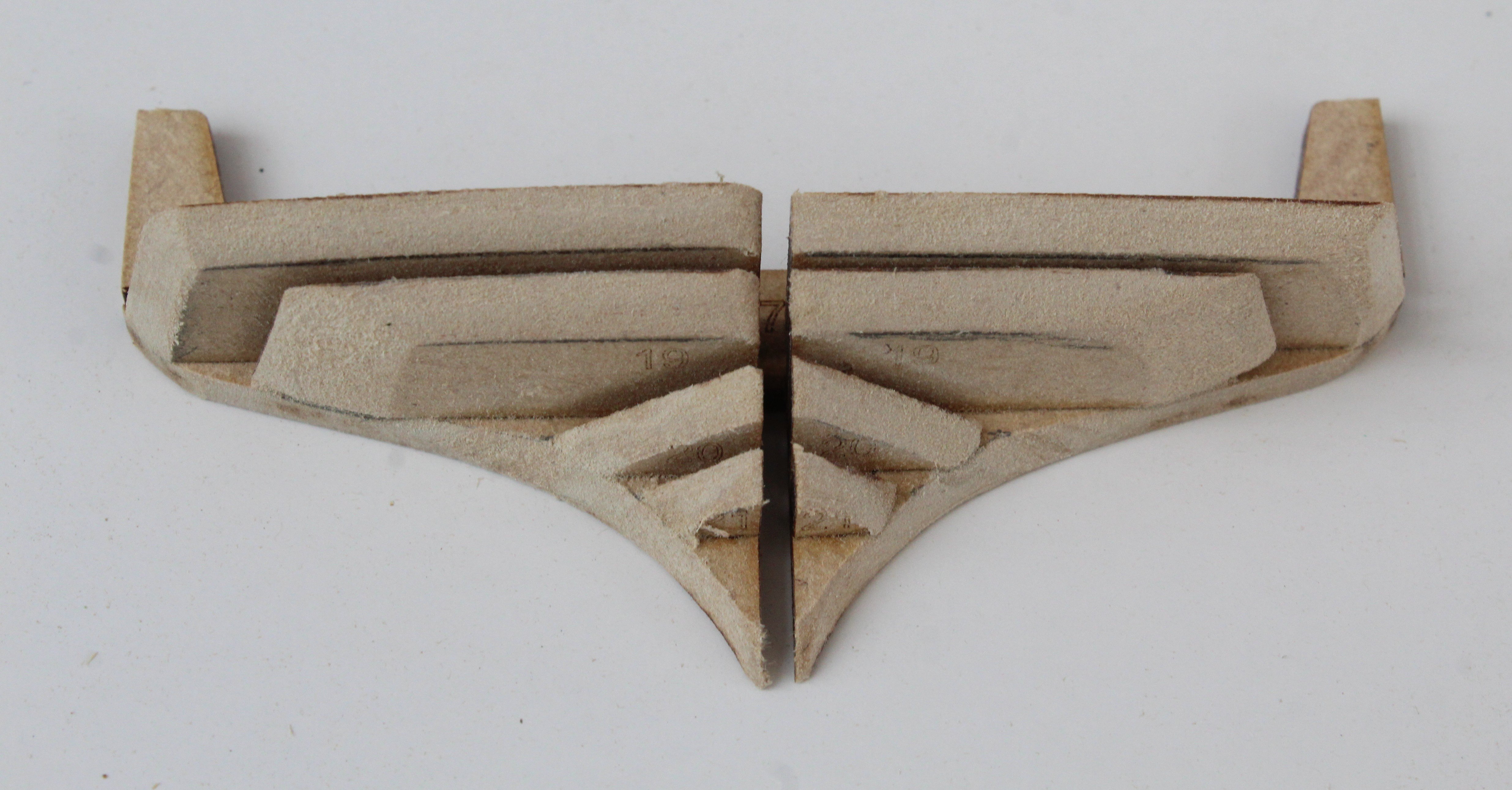
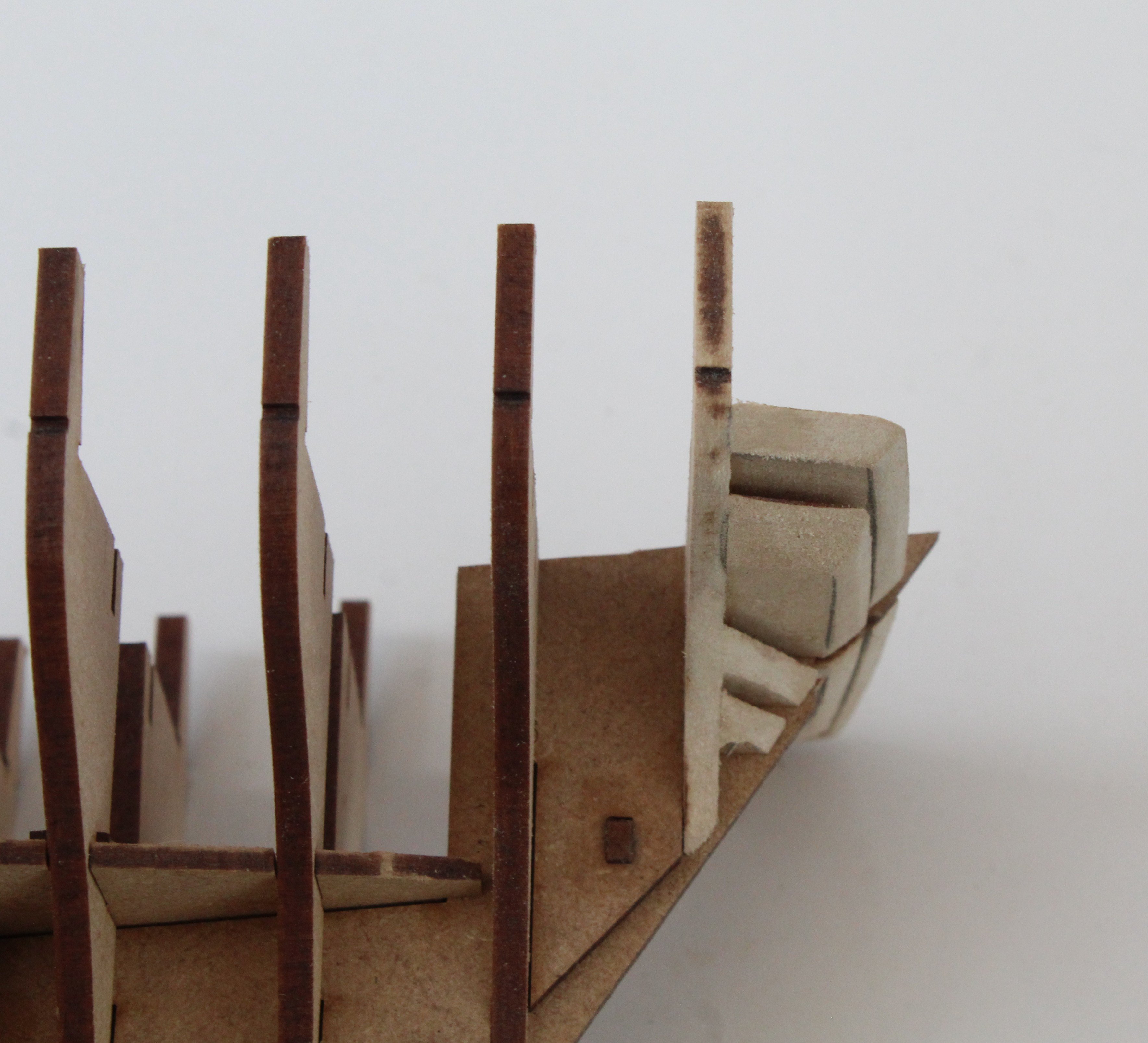
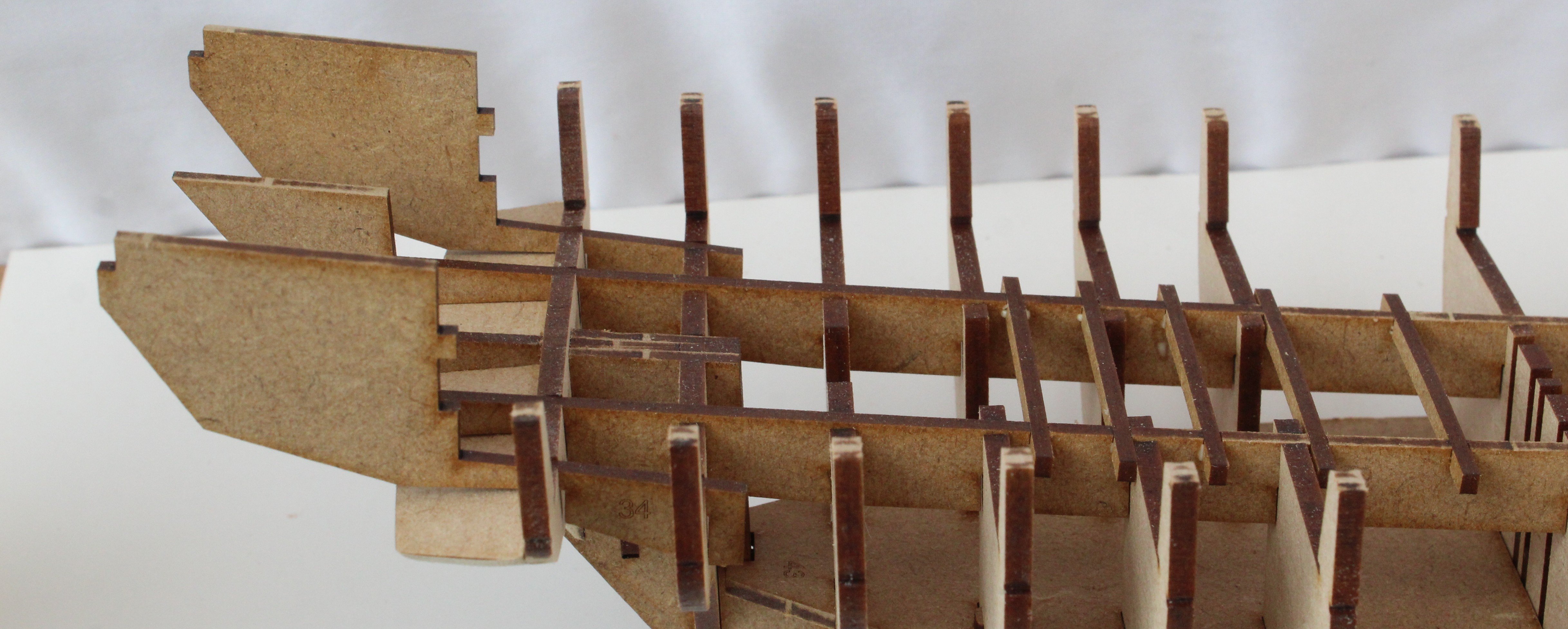
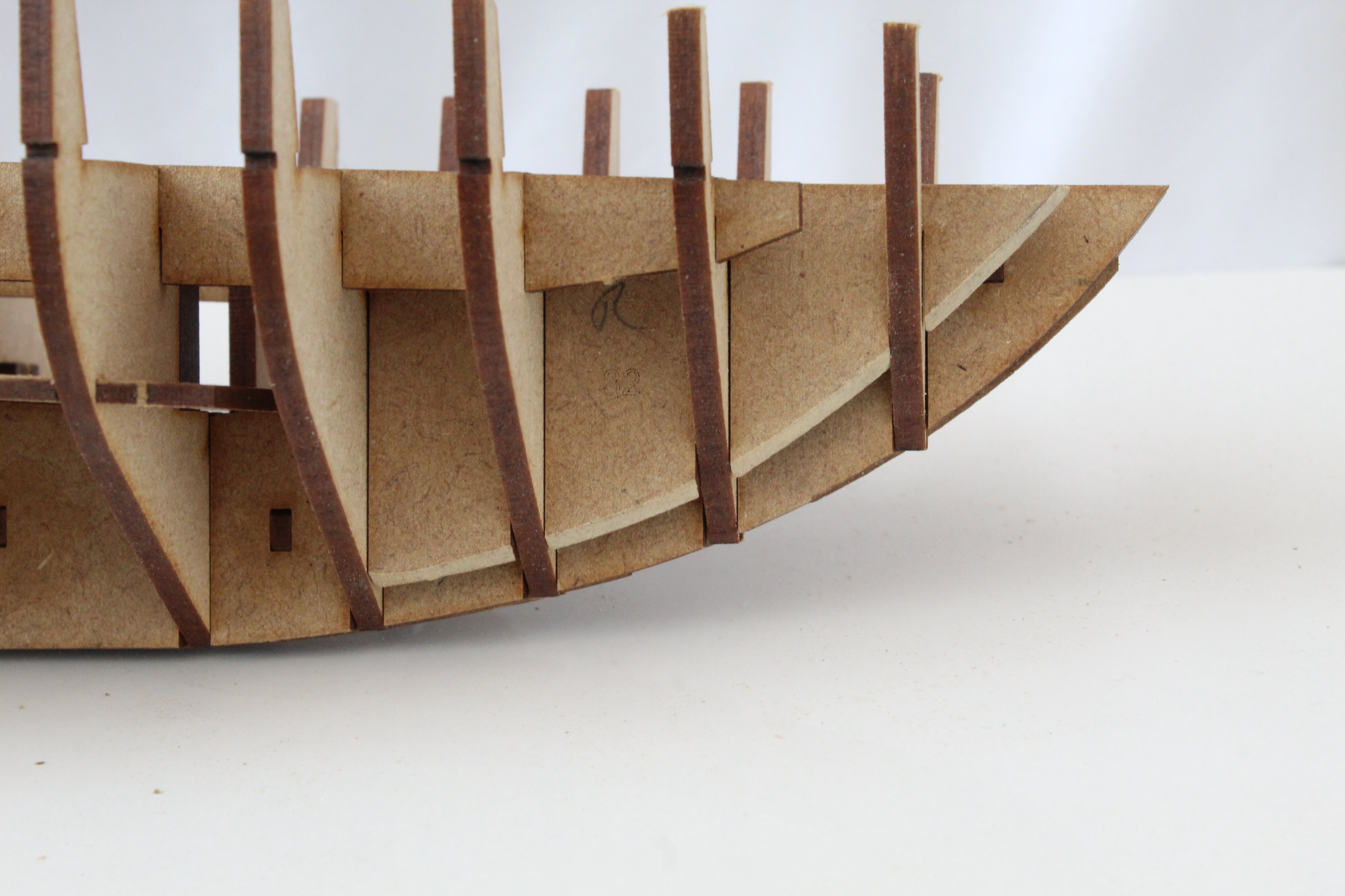
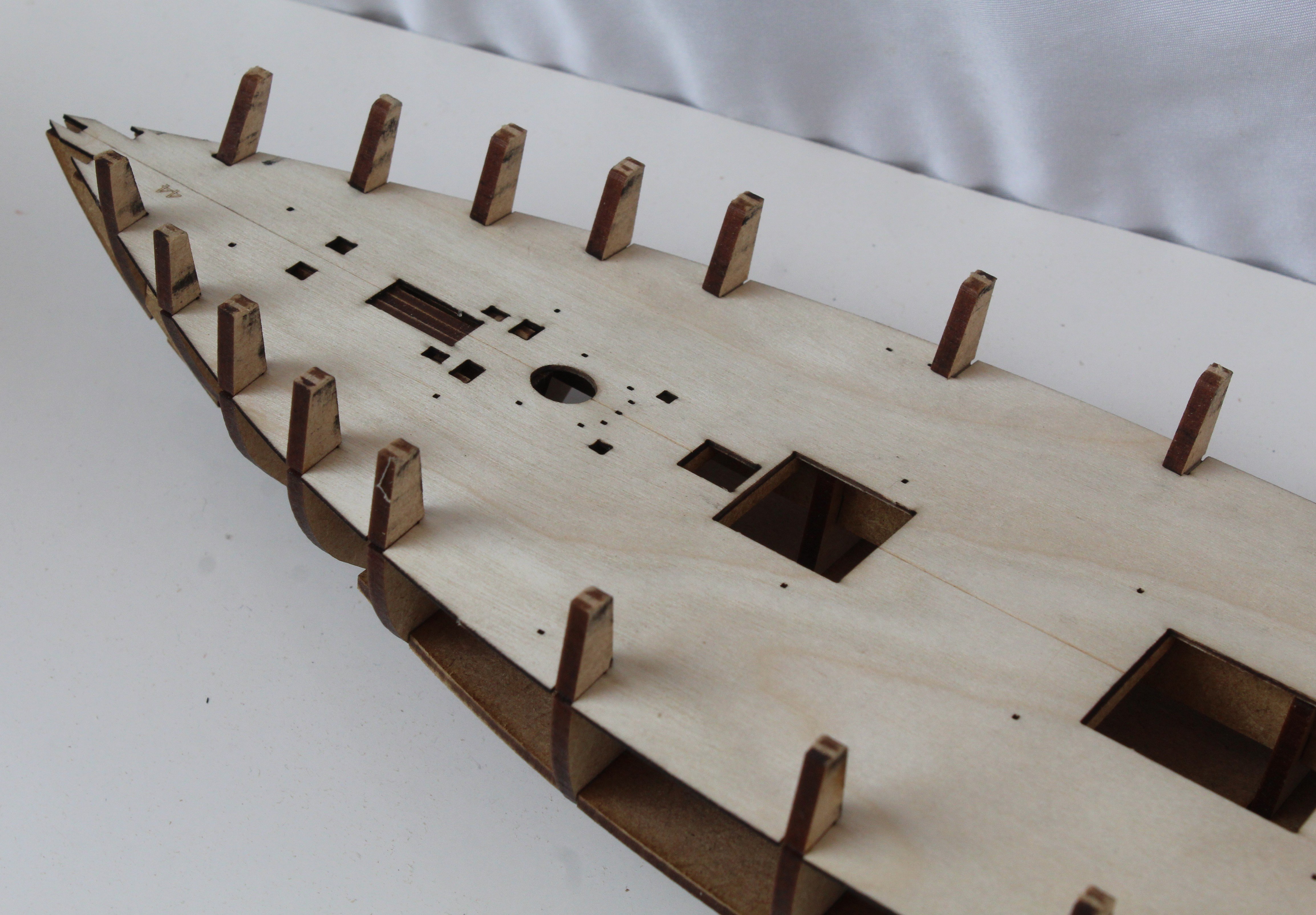
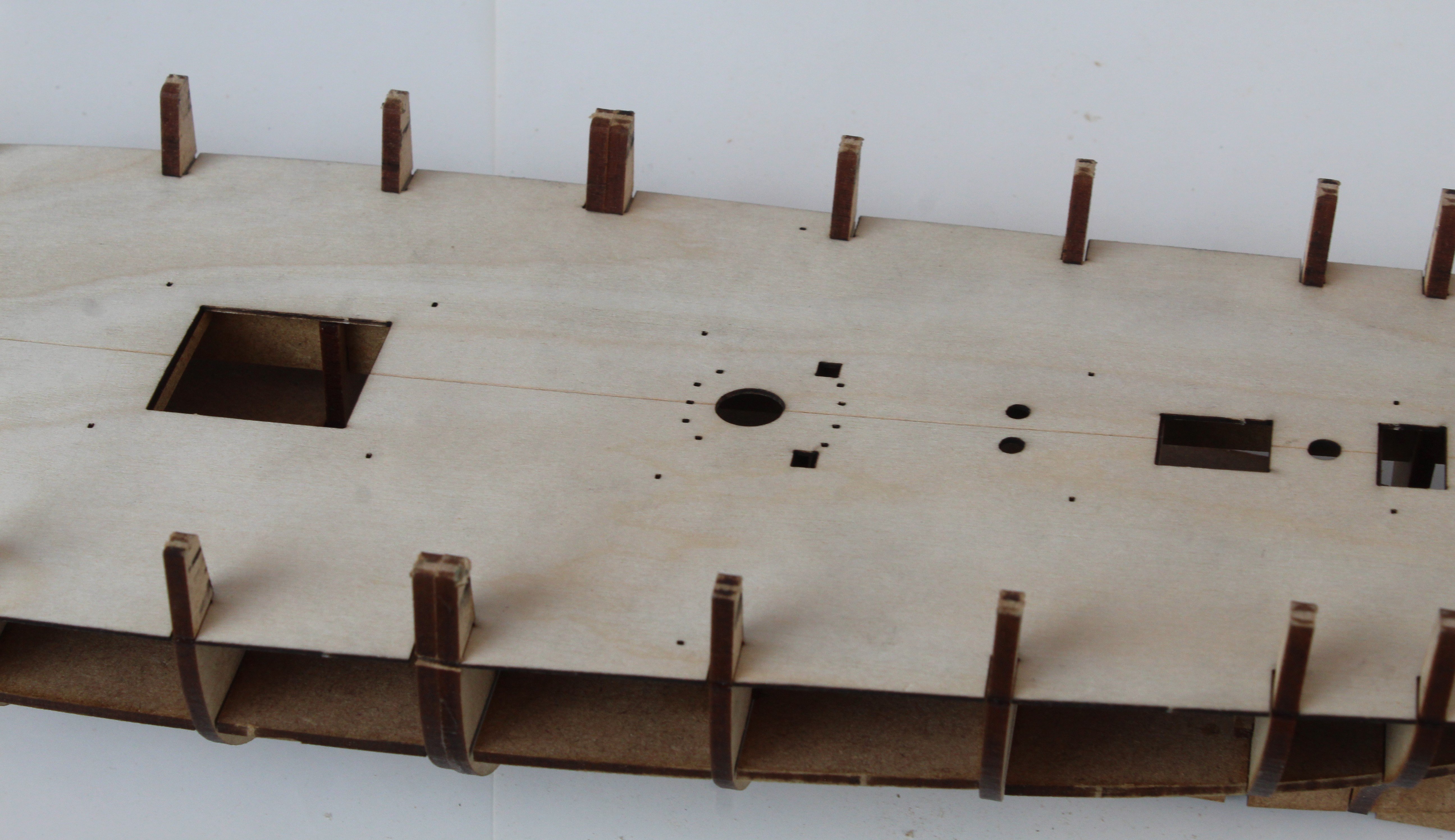
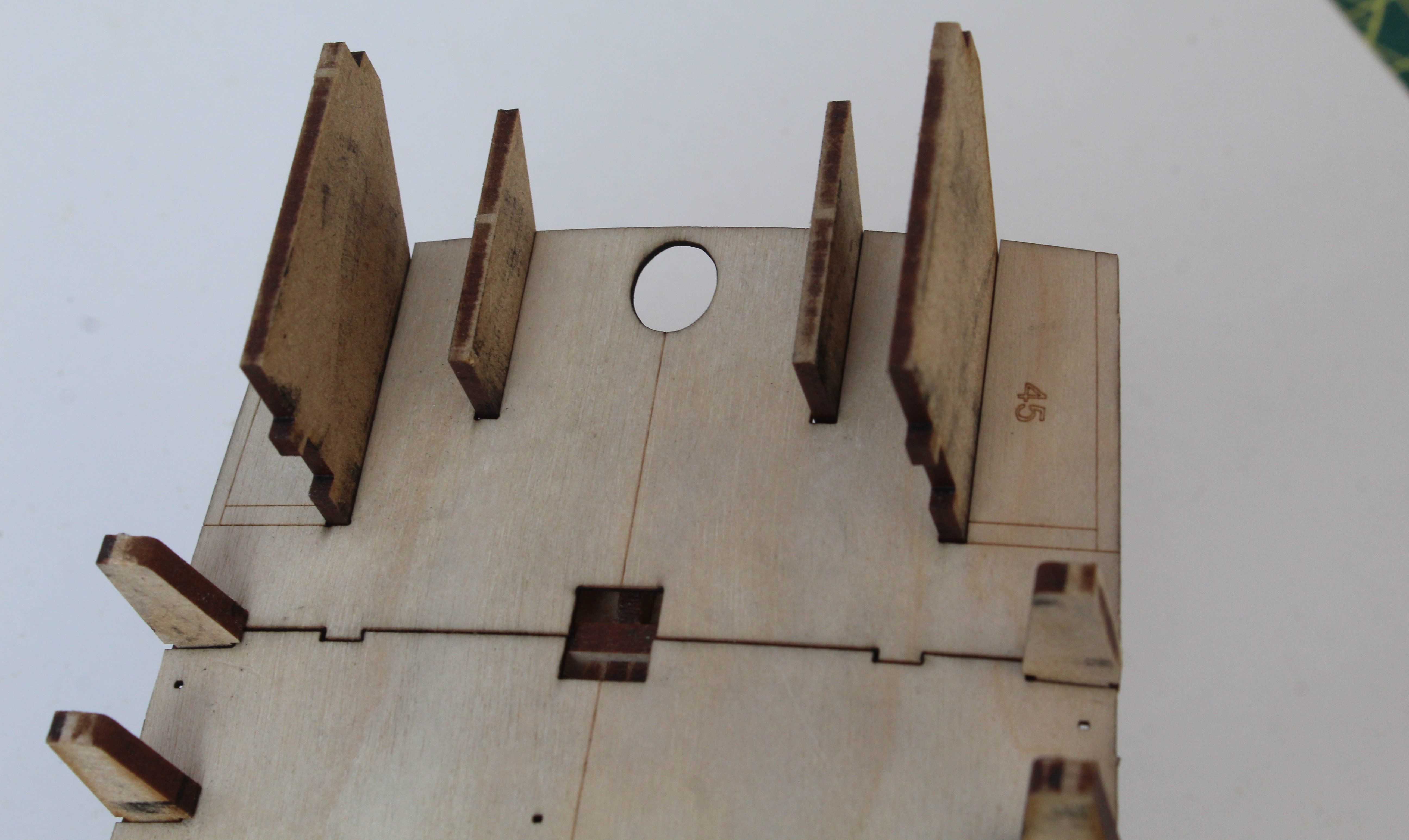
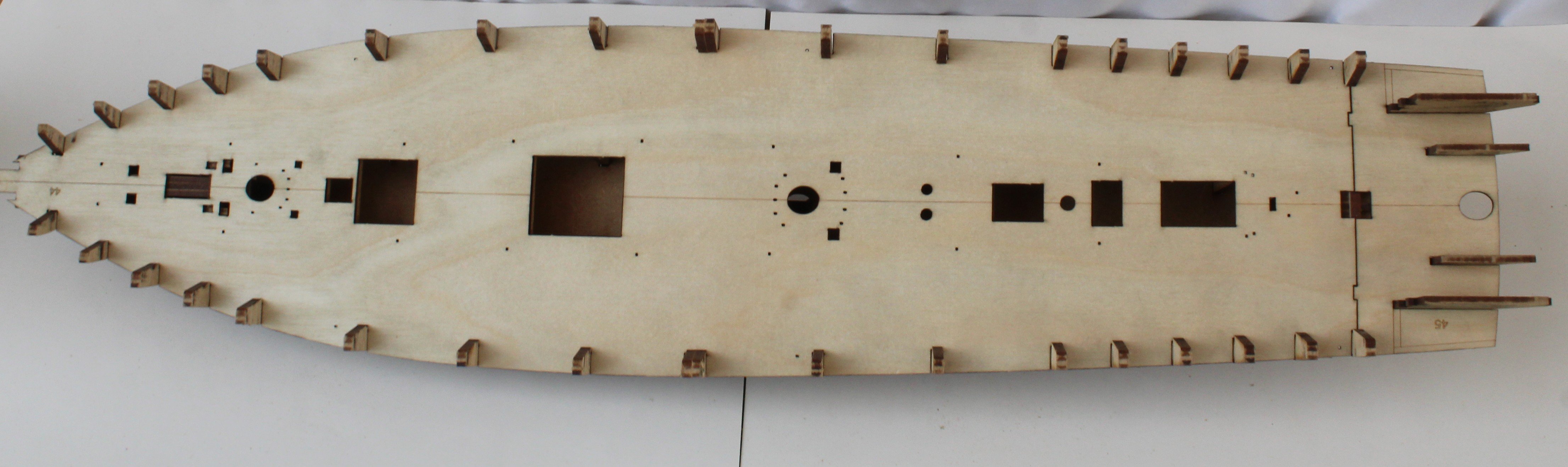
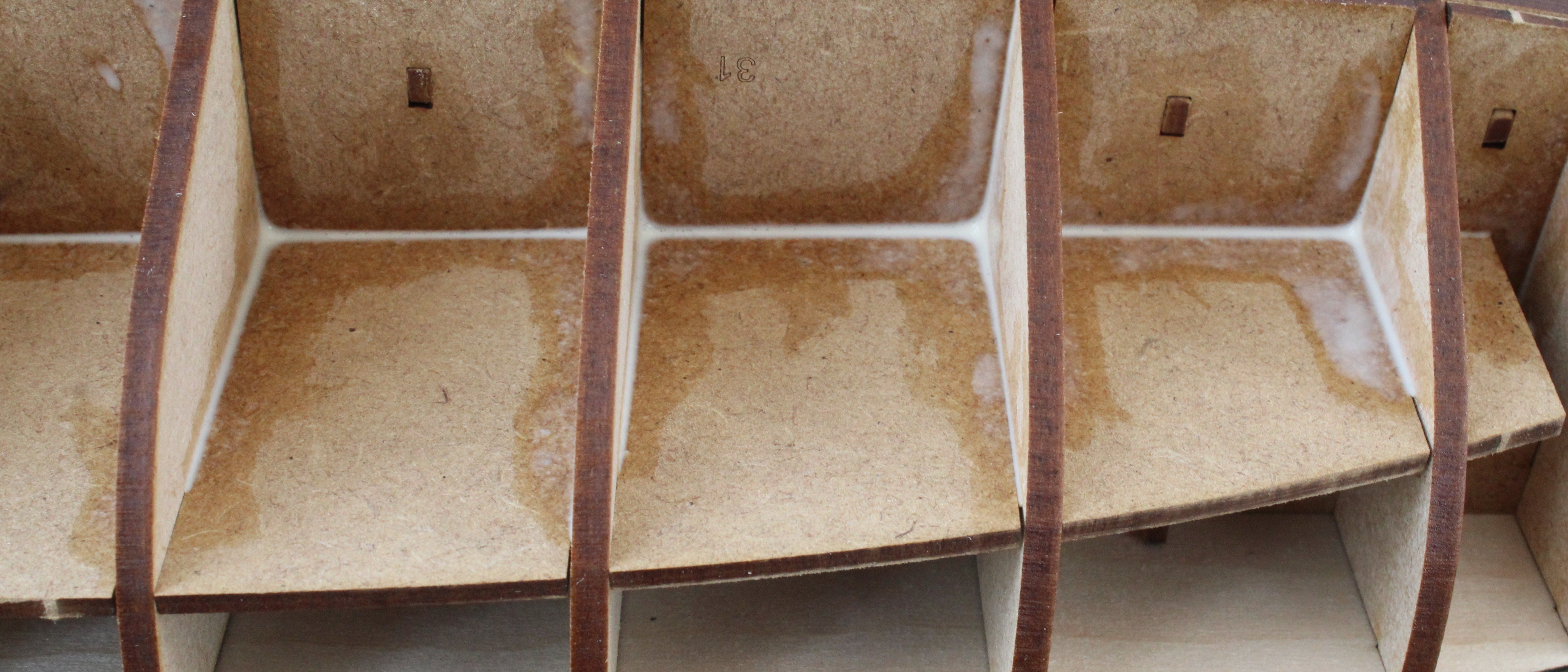
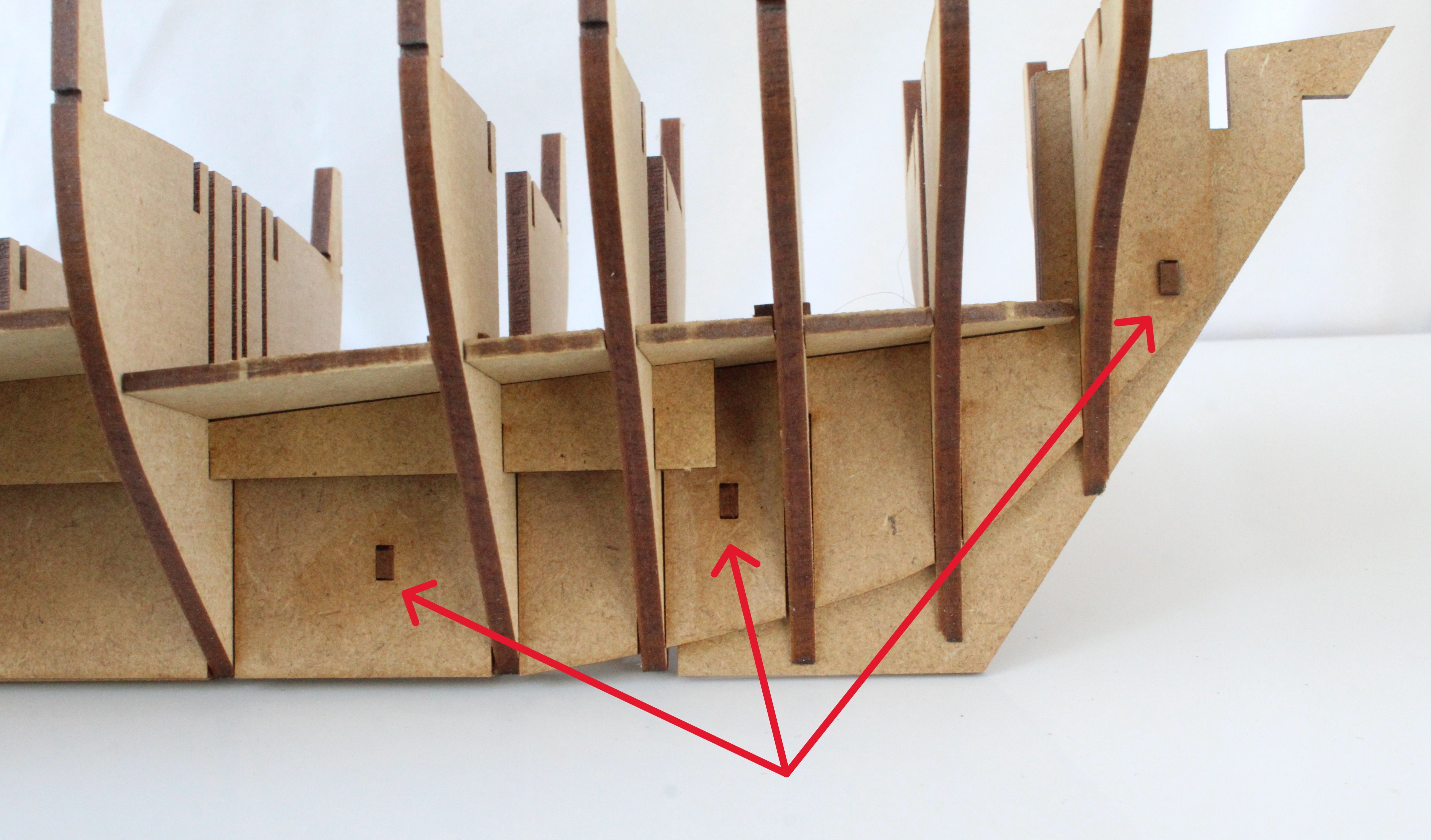
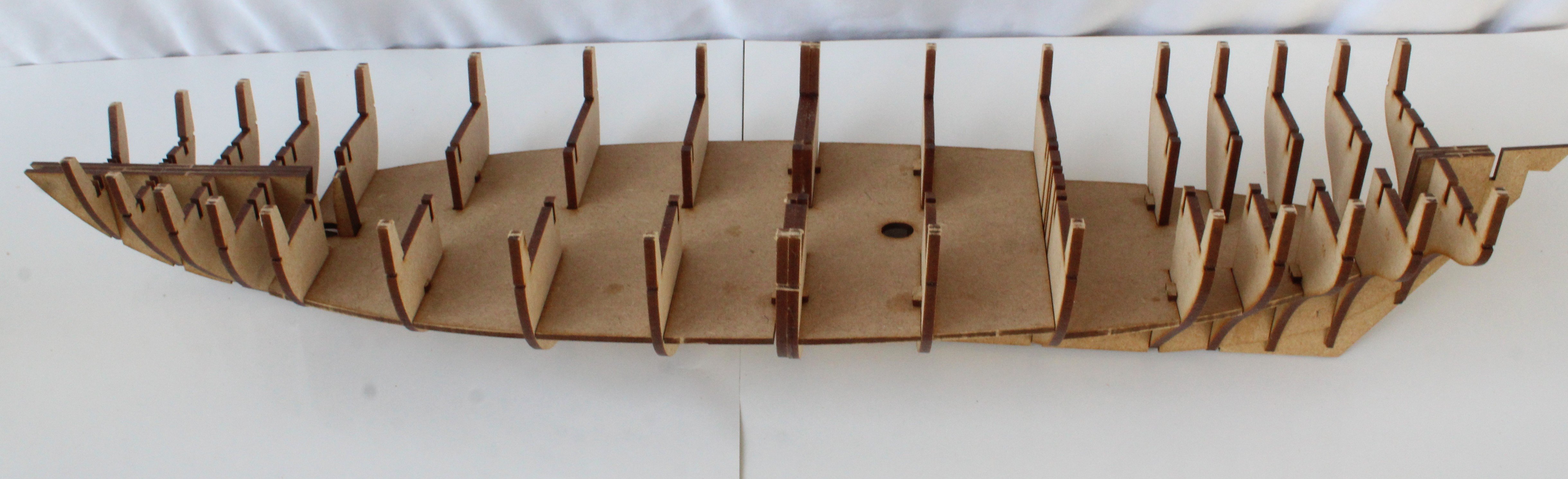
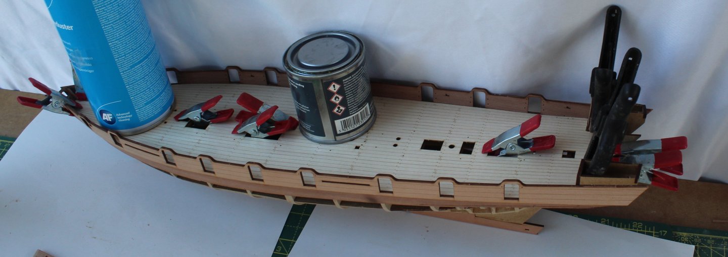
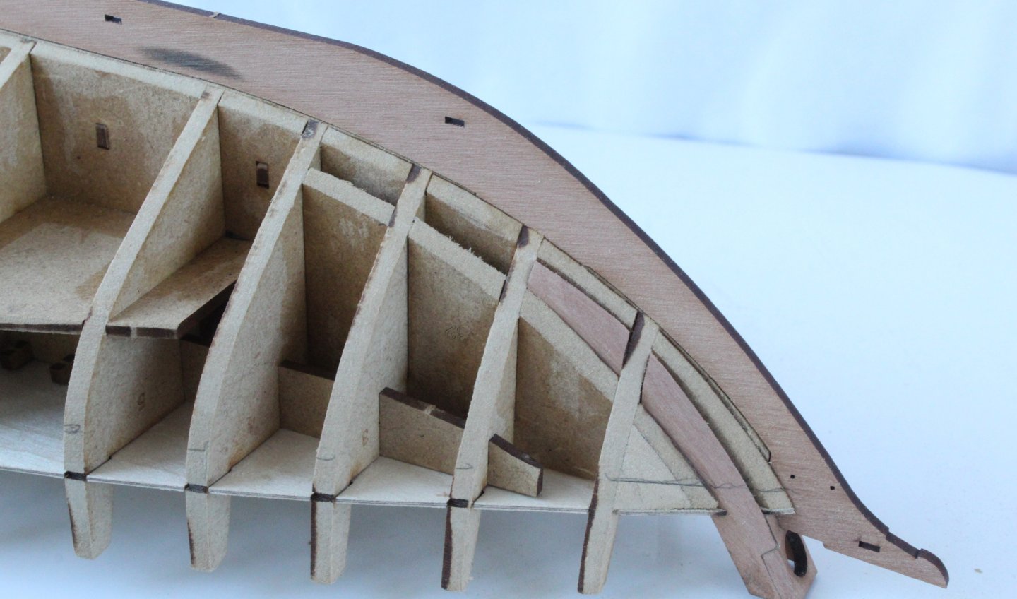
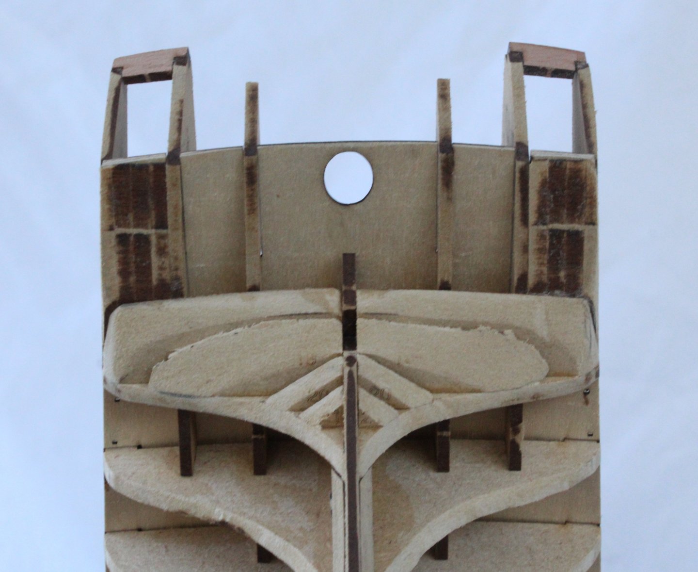
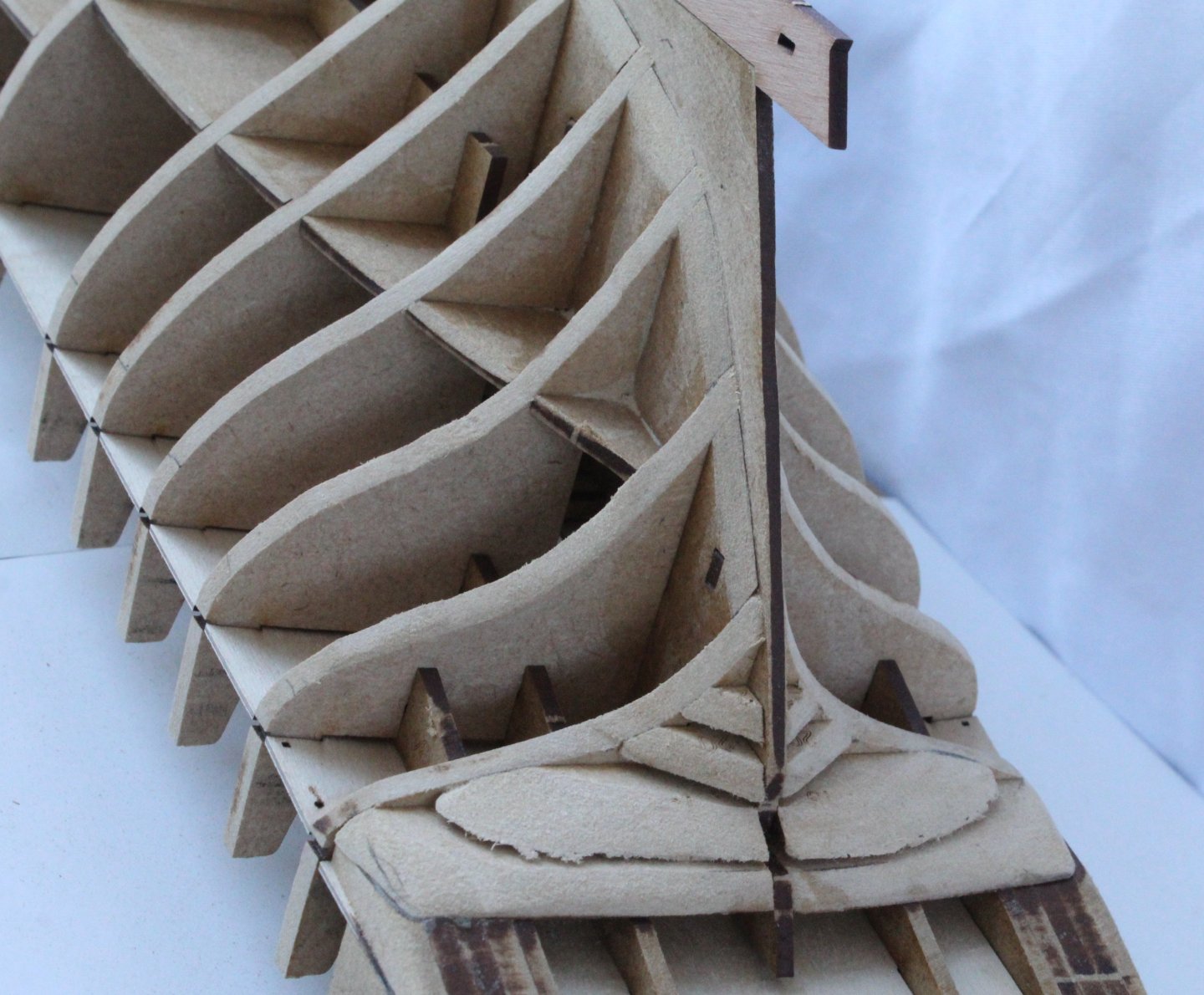
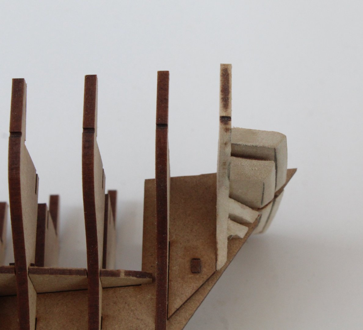
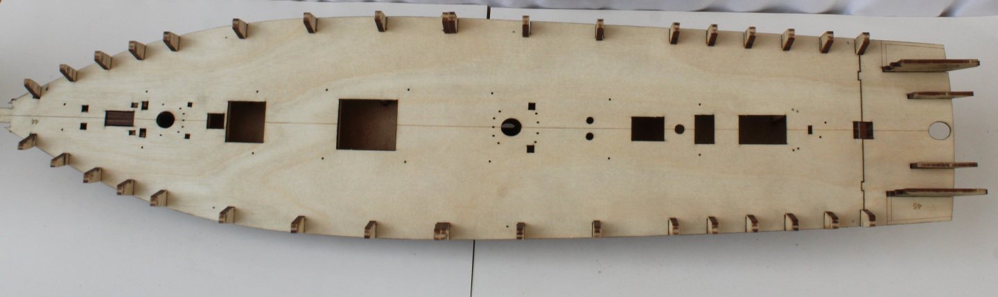
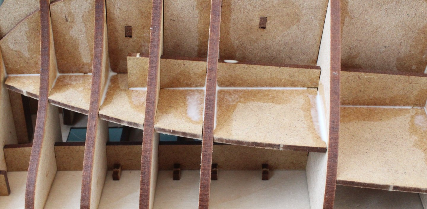
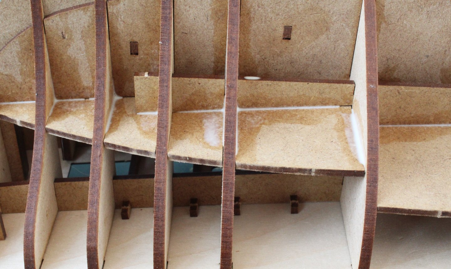
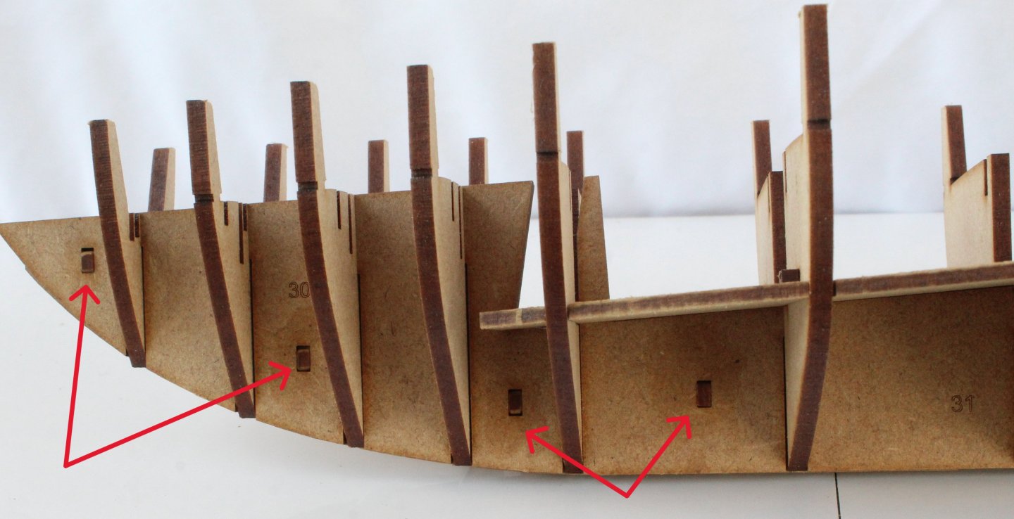
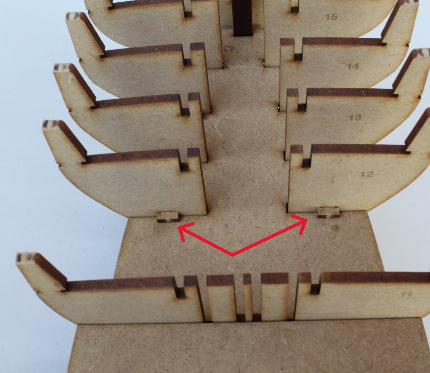
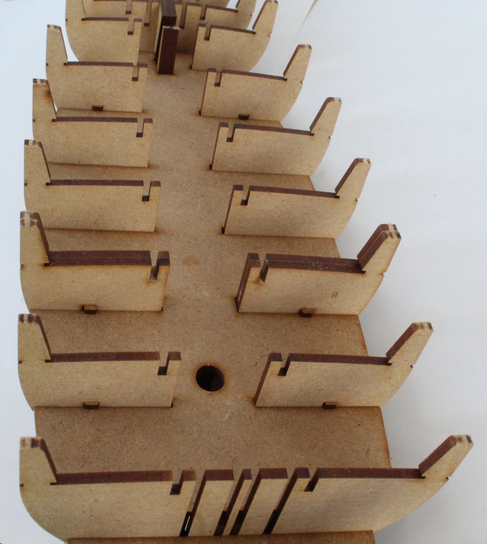
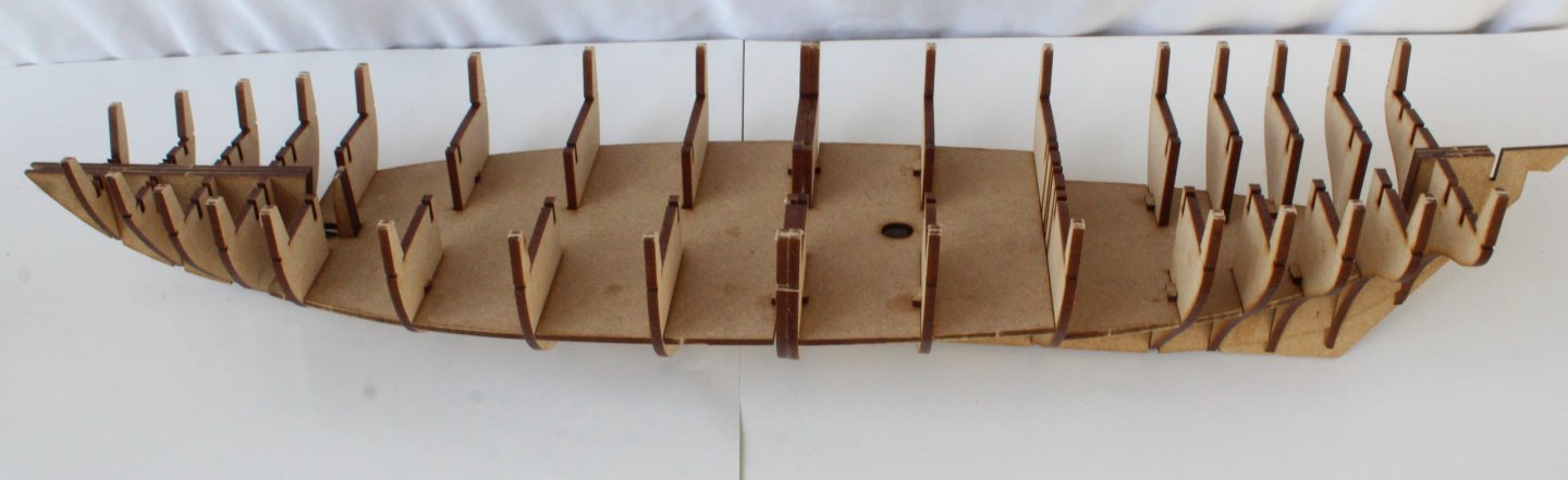
With all work completed on the armaments they are now safely stowed away to be installed at a much later date. It is now time to turn my attention to the hull construction activities and it has been a very productive days work. First task was to add the locking leys to the hull frames. I did removed the laser char from the sides and slightly rounded the leading edge of the locking pins and I was pleased with the relative ease required to fit the keys. More support pieces were then added. The two base decks were then added which are held in place using locking keys. The next task was to assemble bulkhead 17, a test fit was performed, as shown below. Before gluing these parts in place I prefer to pre fair the various parts. I have marked up the various parts. The next photo shows the parts after they have been faired. The parts were then glued in place and only required a little bit more sanding. Bulkhead 17 was then added to the hull. Next task was to add the various deck beams. I did also pre fair one of the bow shapers. The next task was to add the 0.8mm deck patterns. The main deck section was slotted over the bulkhead ears and with a little bit of gentle persuasion the part clicked into place in to all the locating slots. The rear deck section was then added. All looks good so far. The hull was then inverted so diluted glue could be brushed into the joints. As I progressed on with the next couple of stages I realised that I had somehow missed adding the inner most bow shaper (left and right). Thankfully I was able to release the plywood deck and to then insert the missing parts. The deck was then clipped back in place.


-
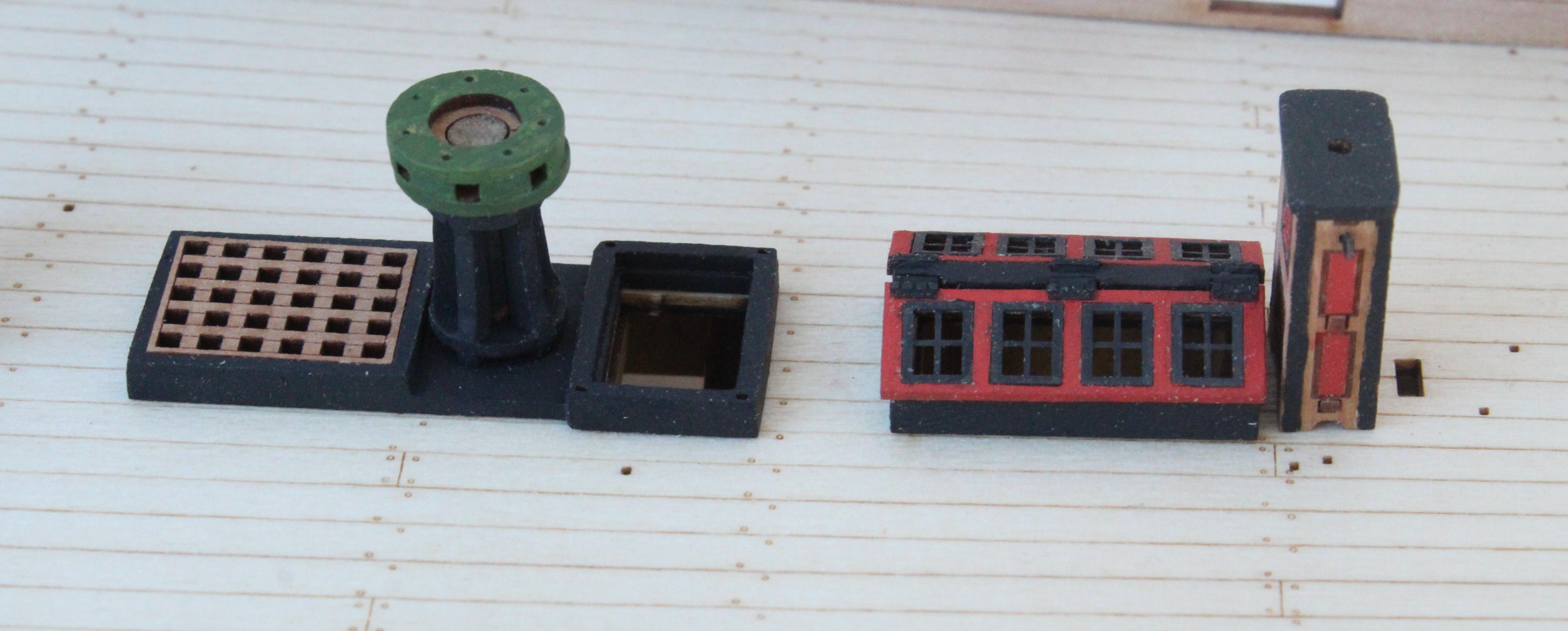
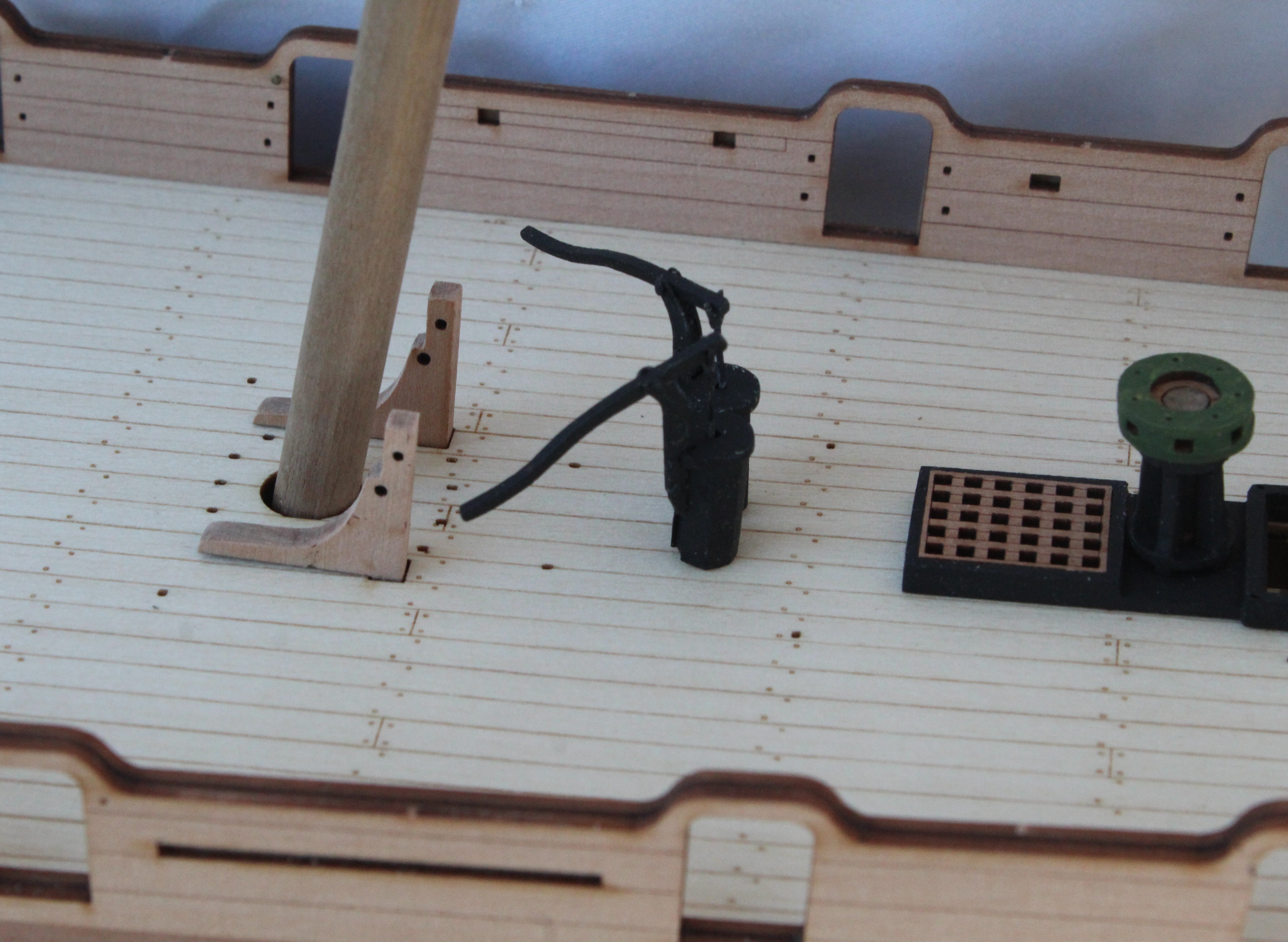
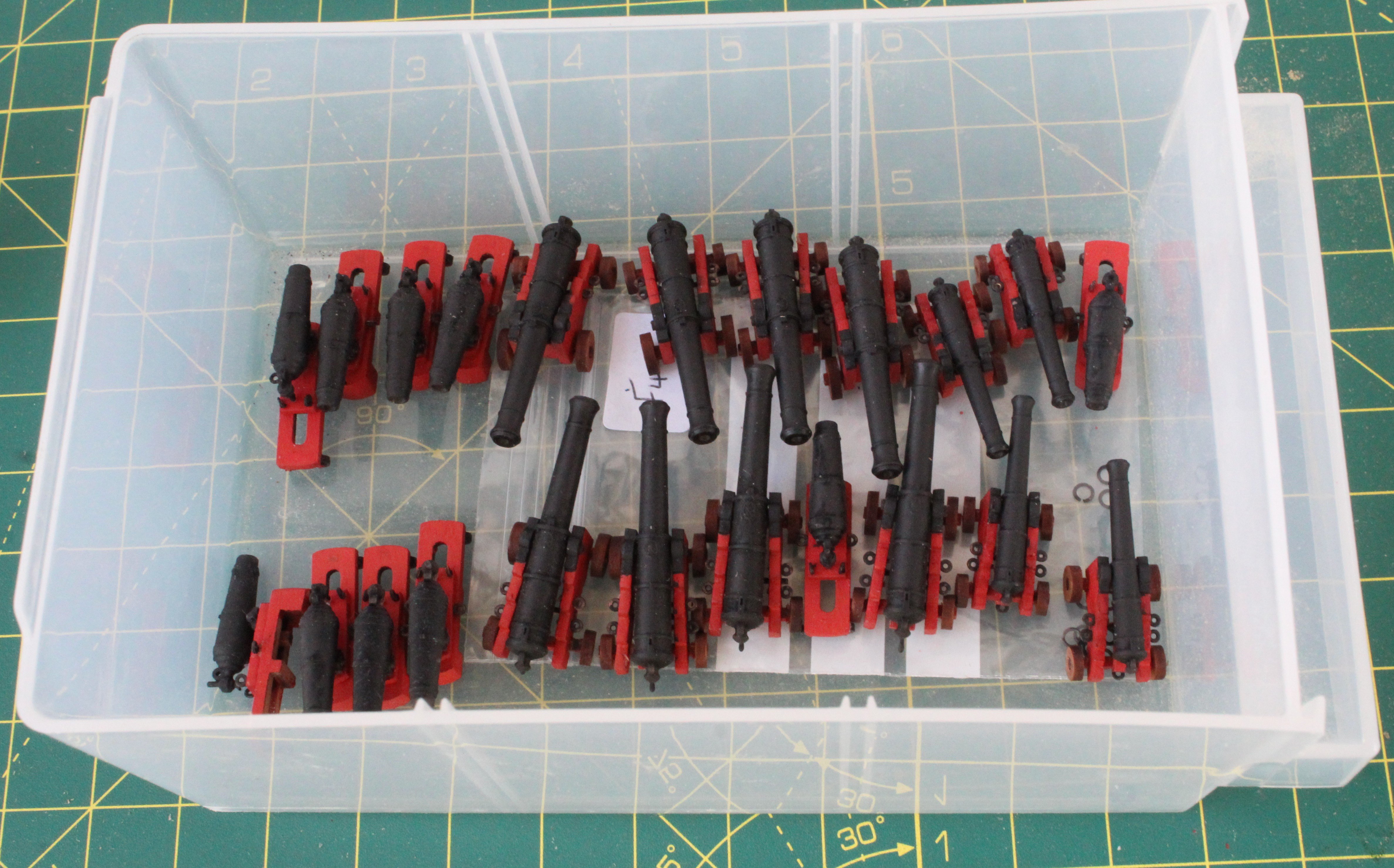
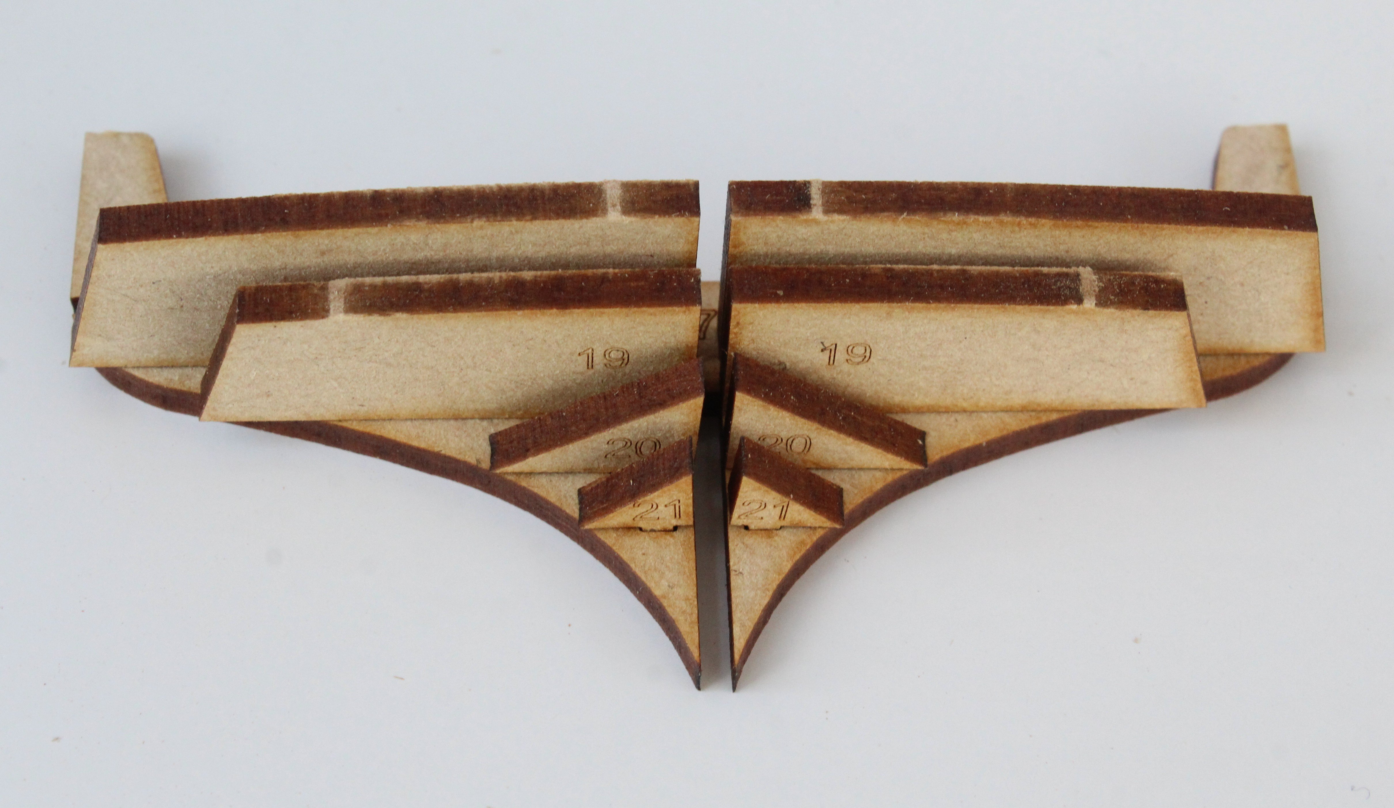
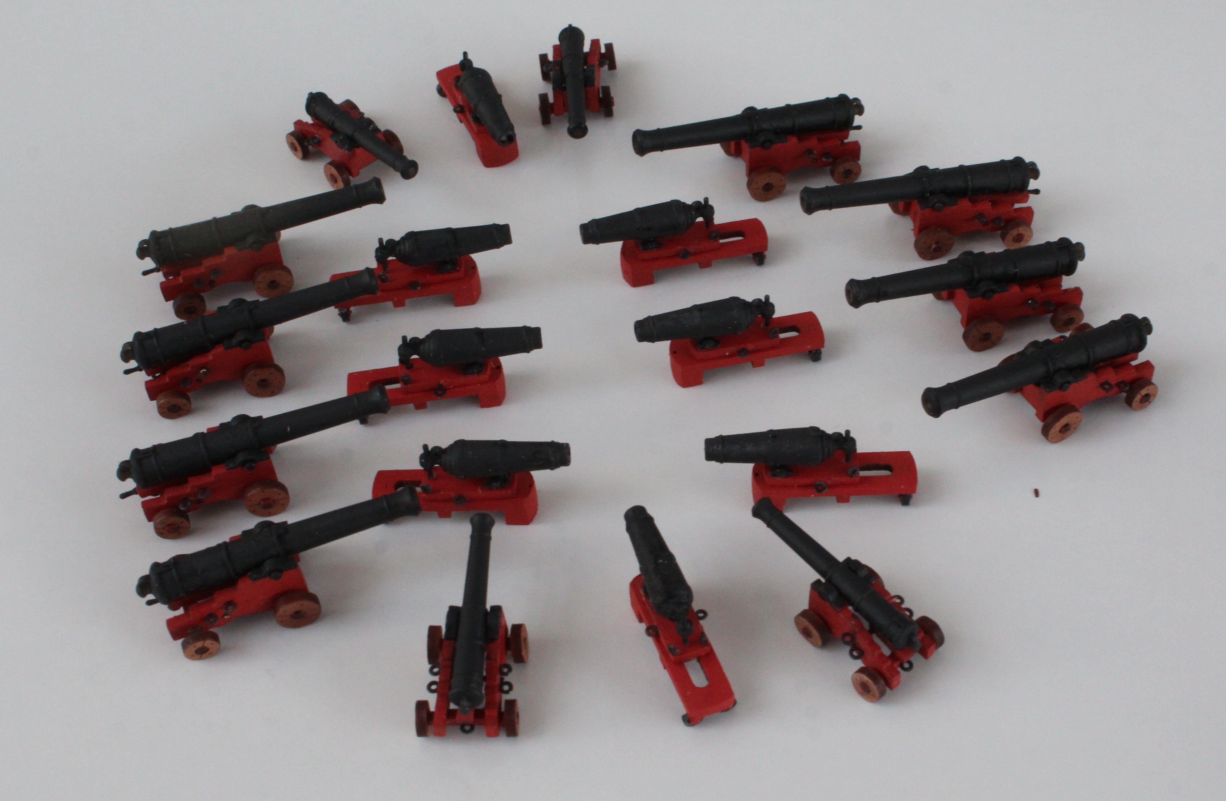
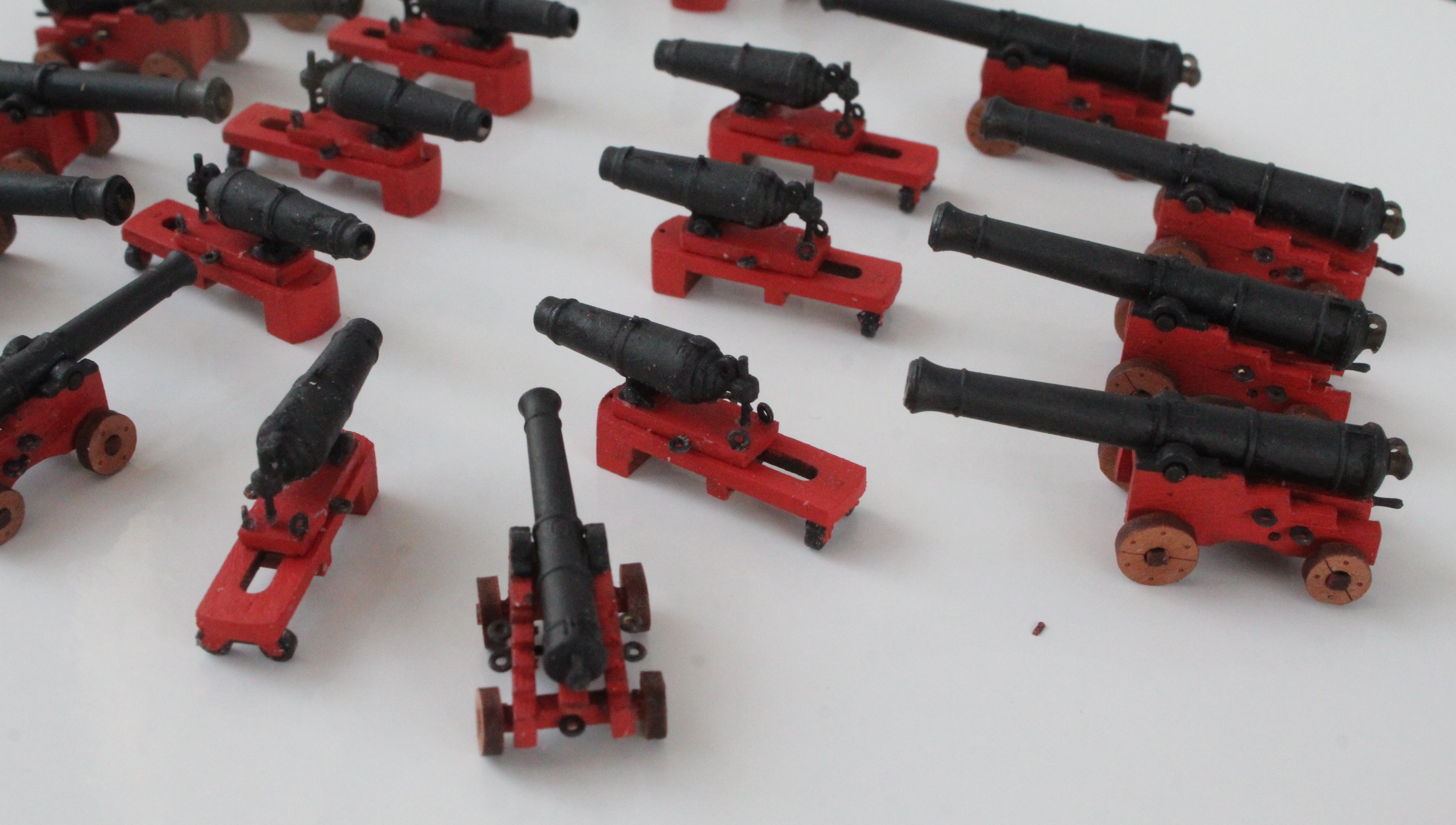
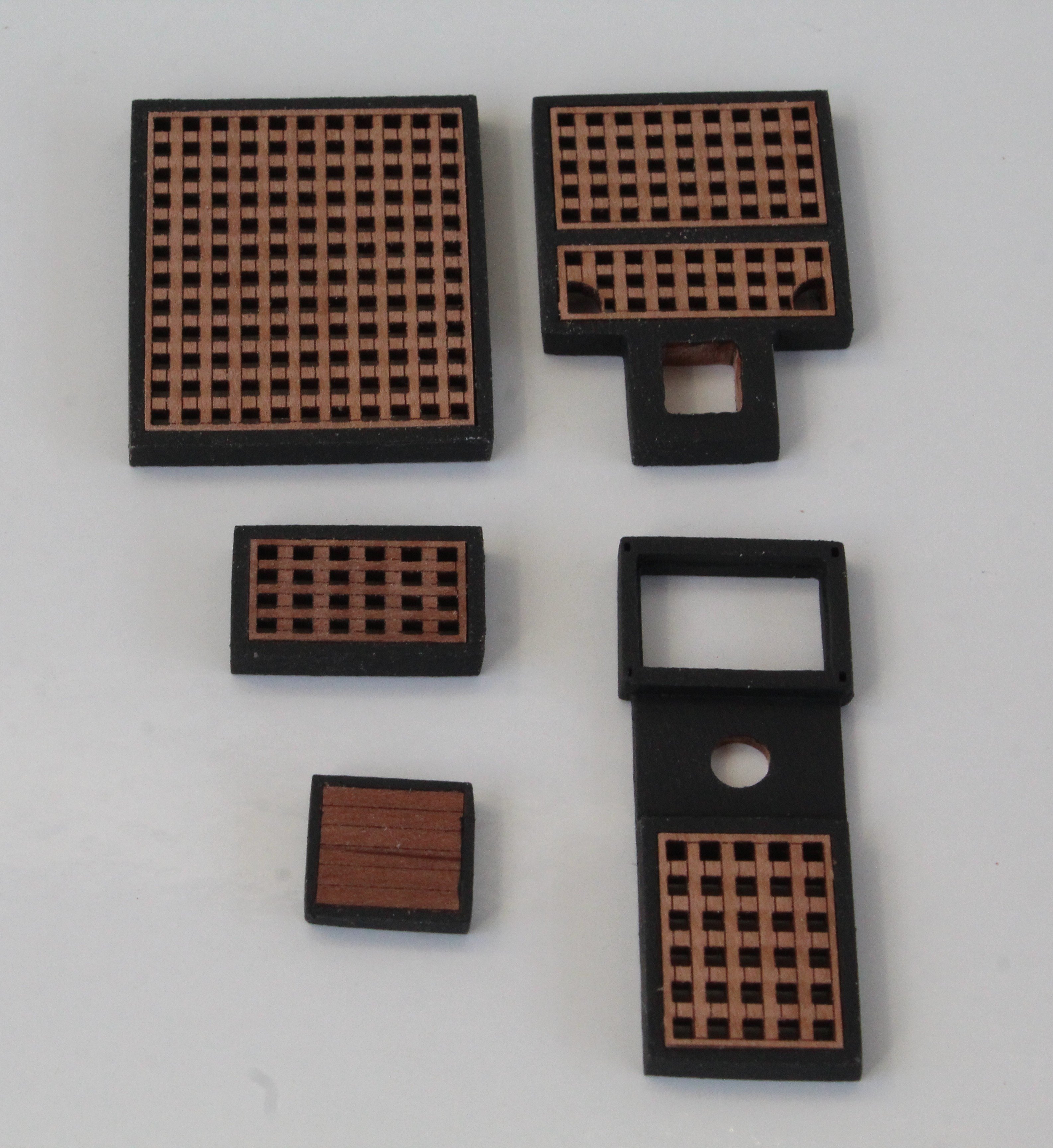
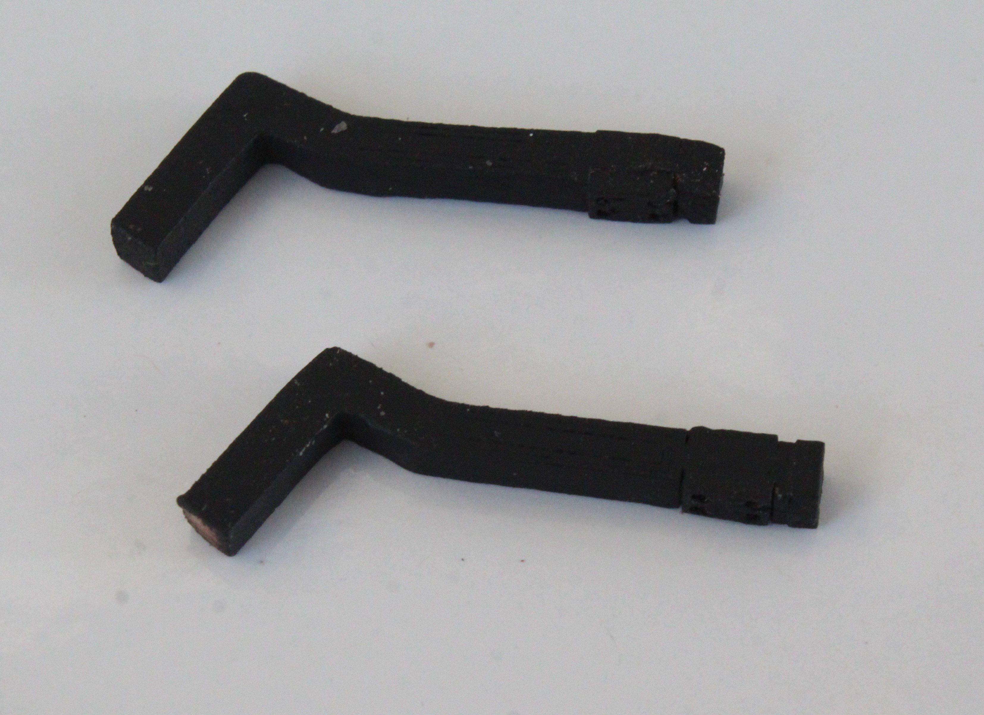
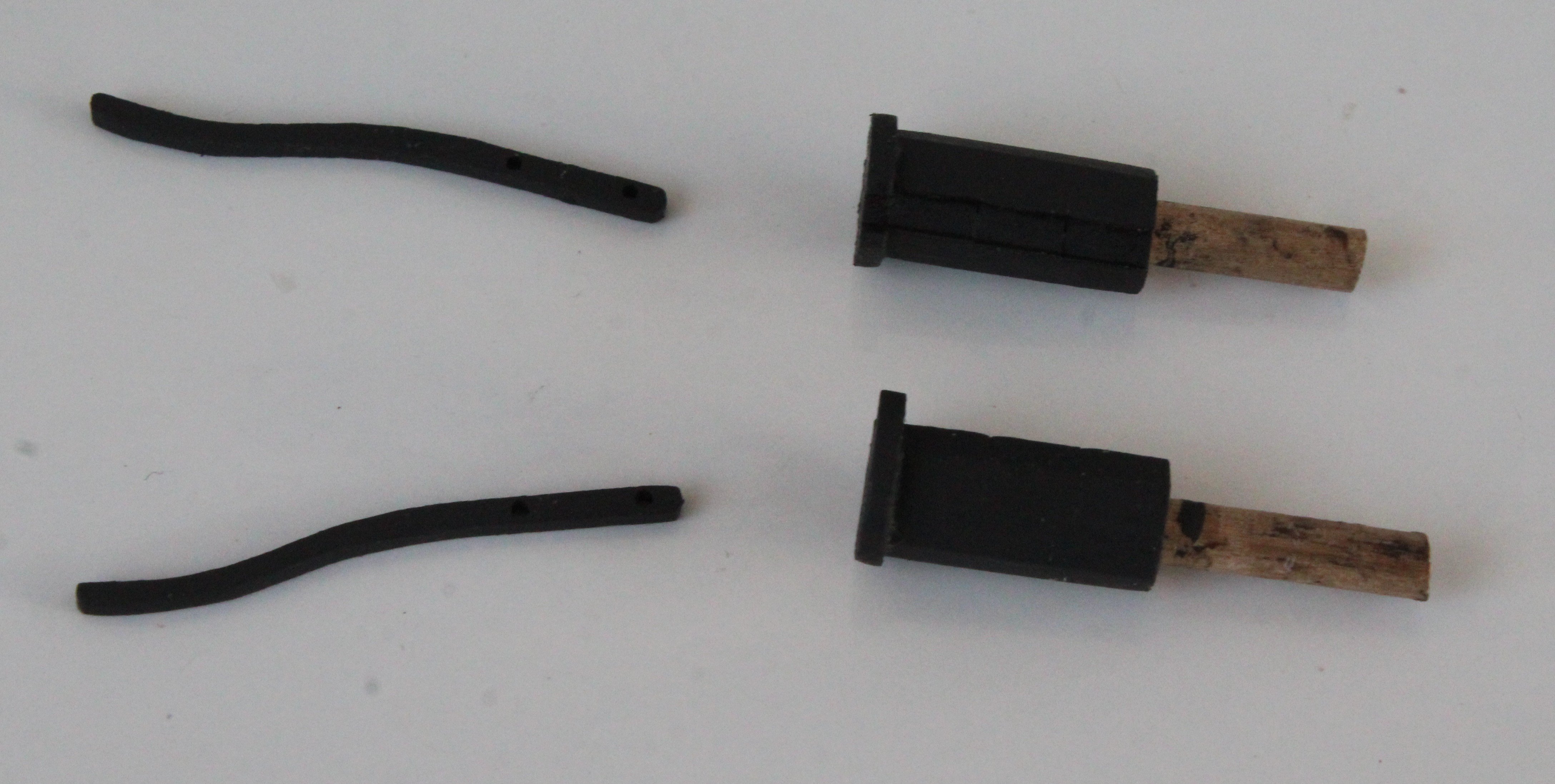
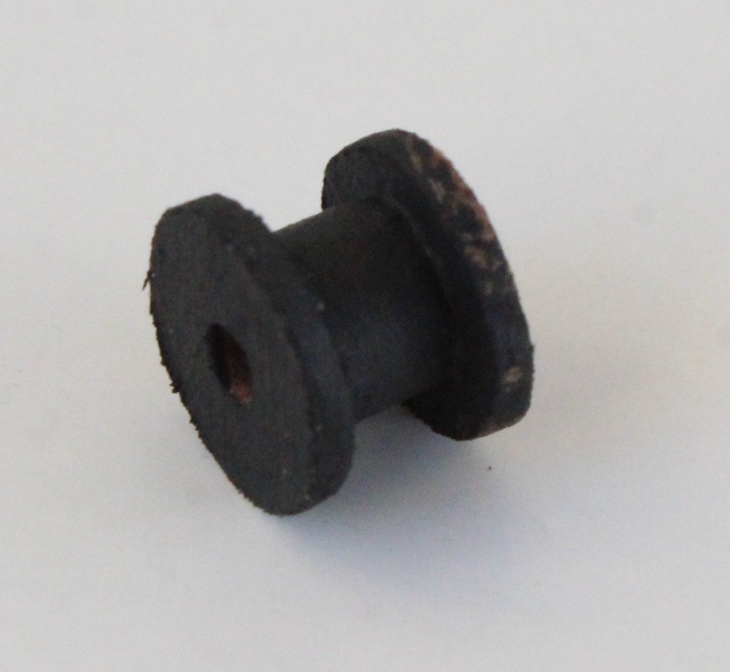
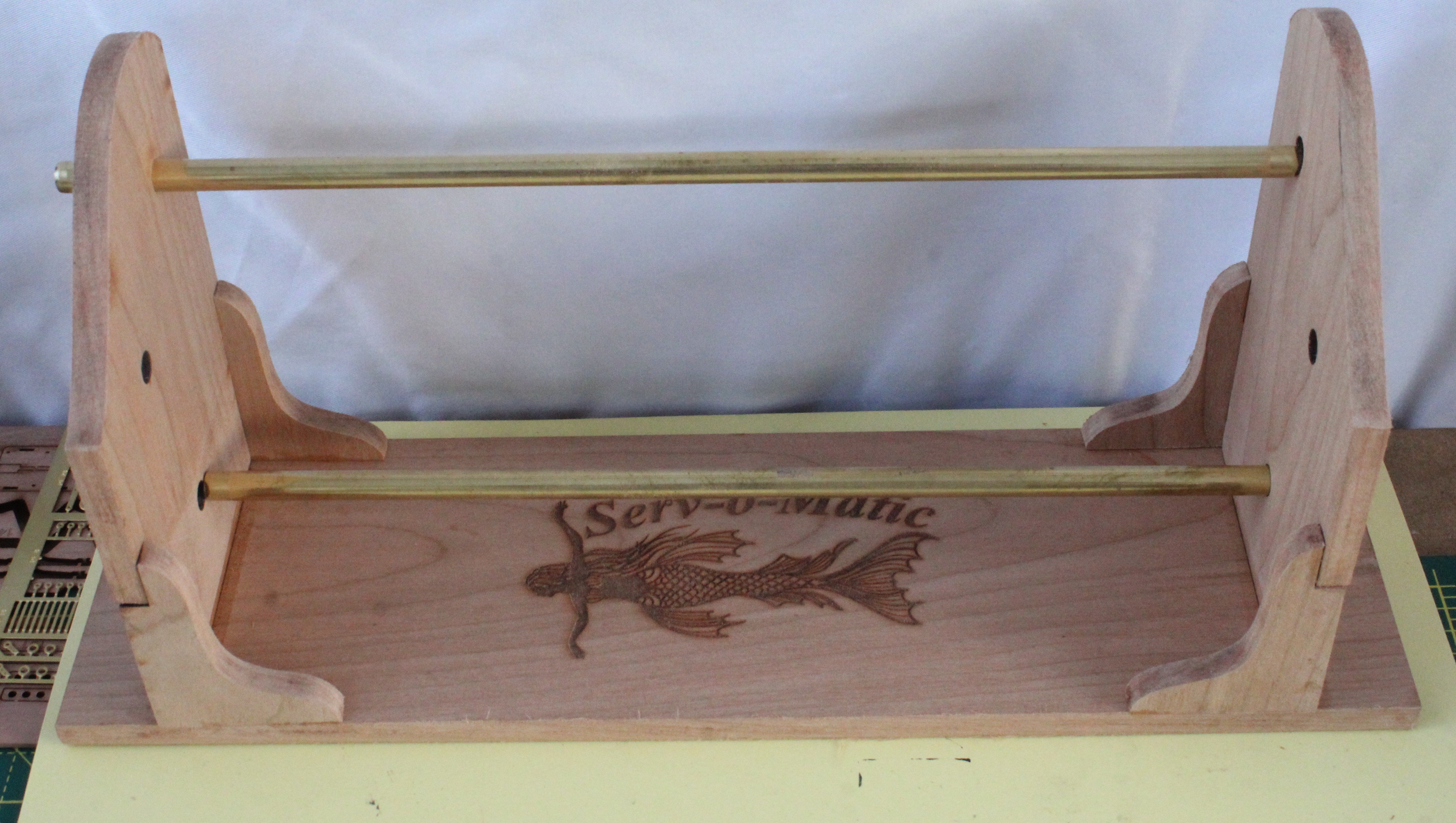
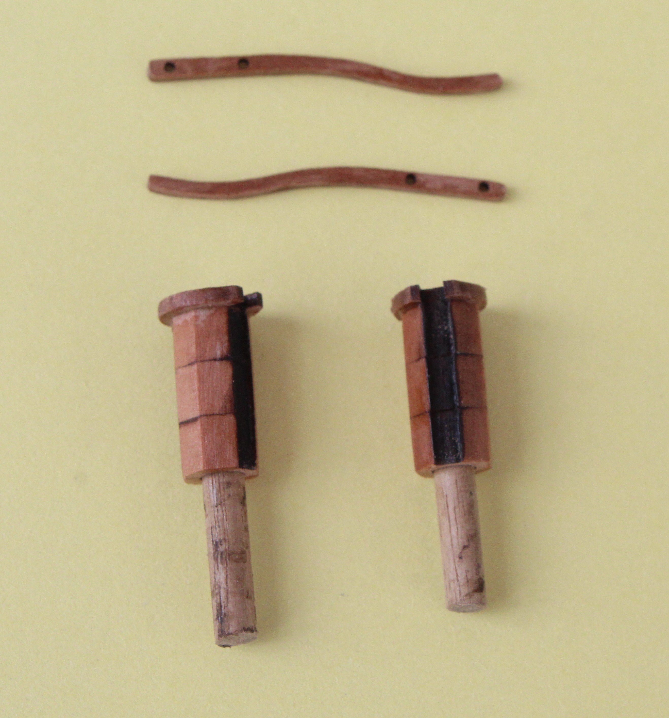
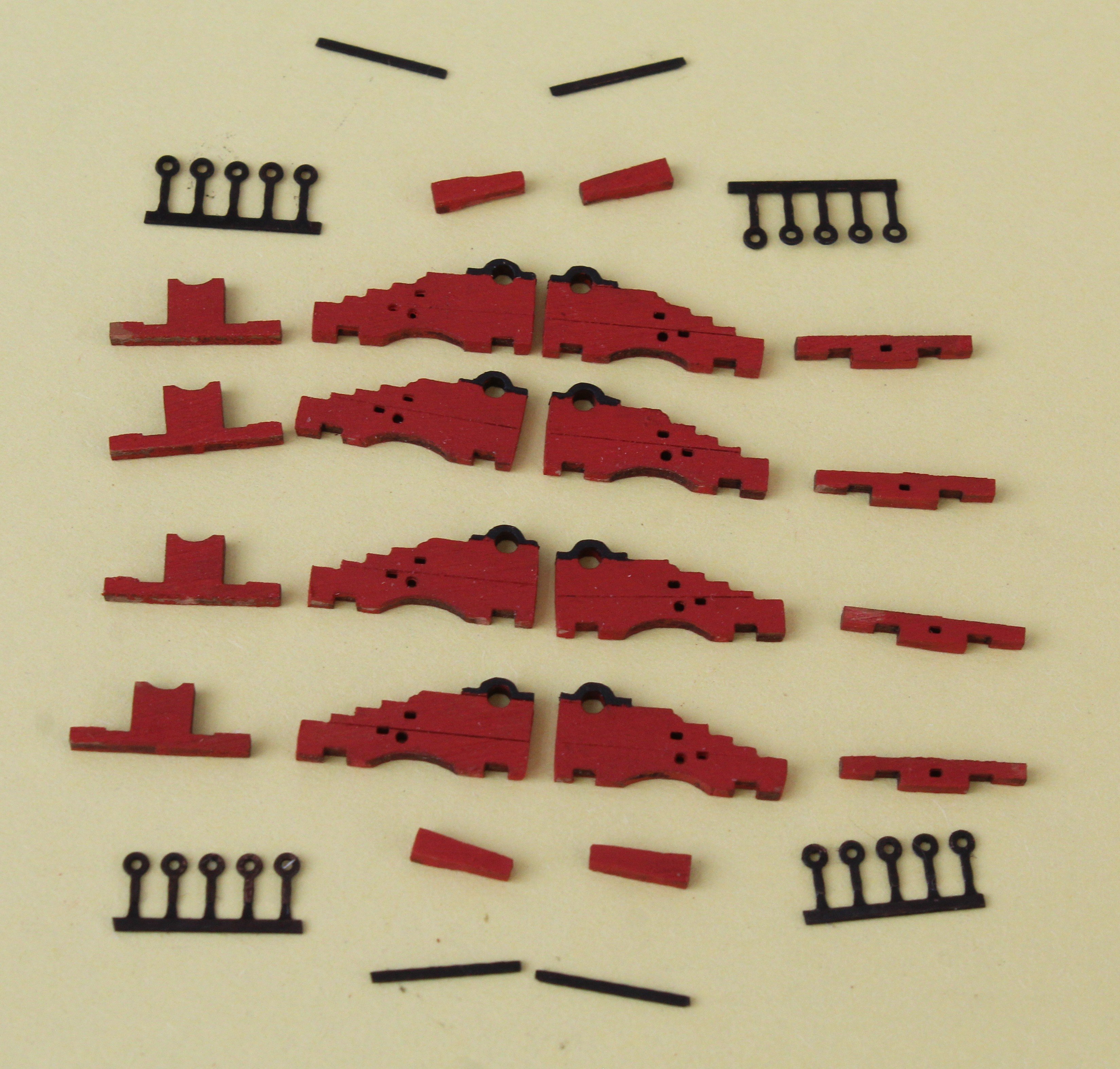
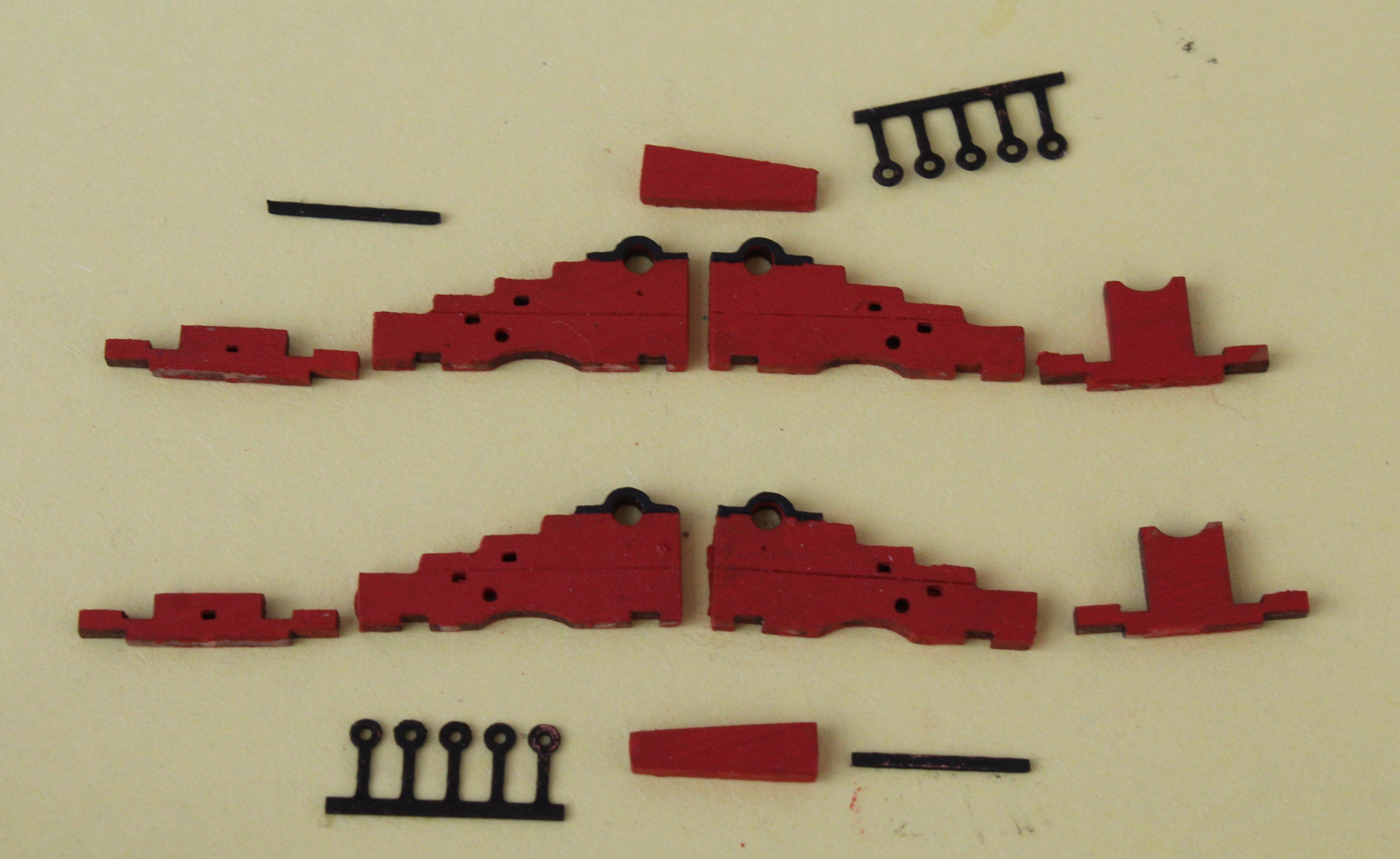
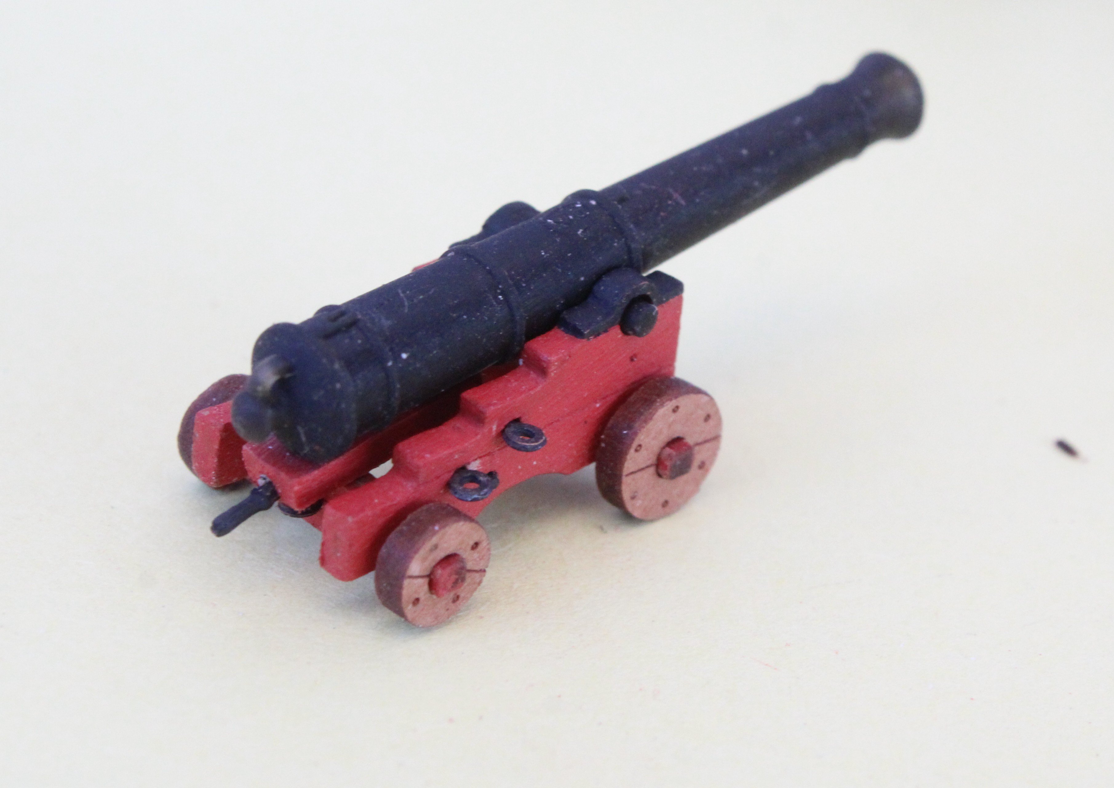
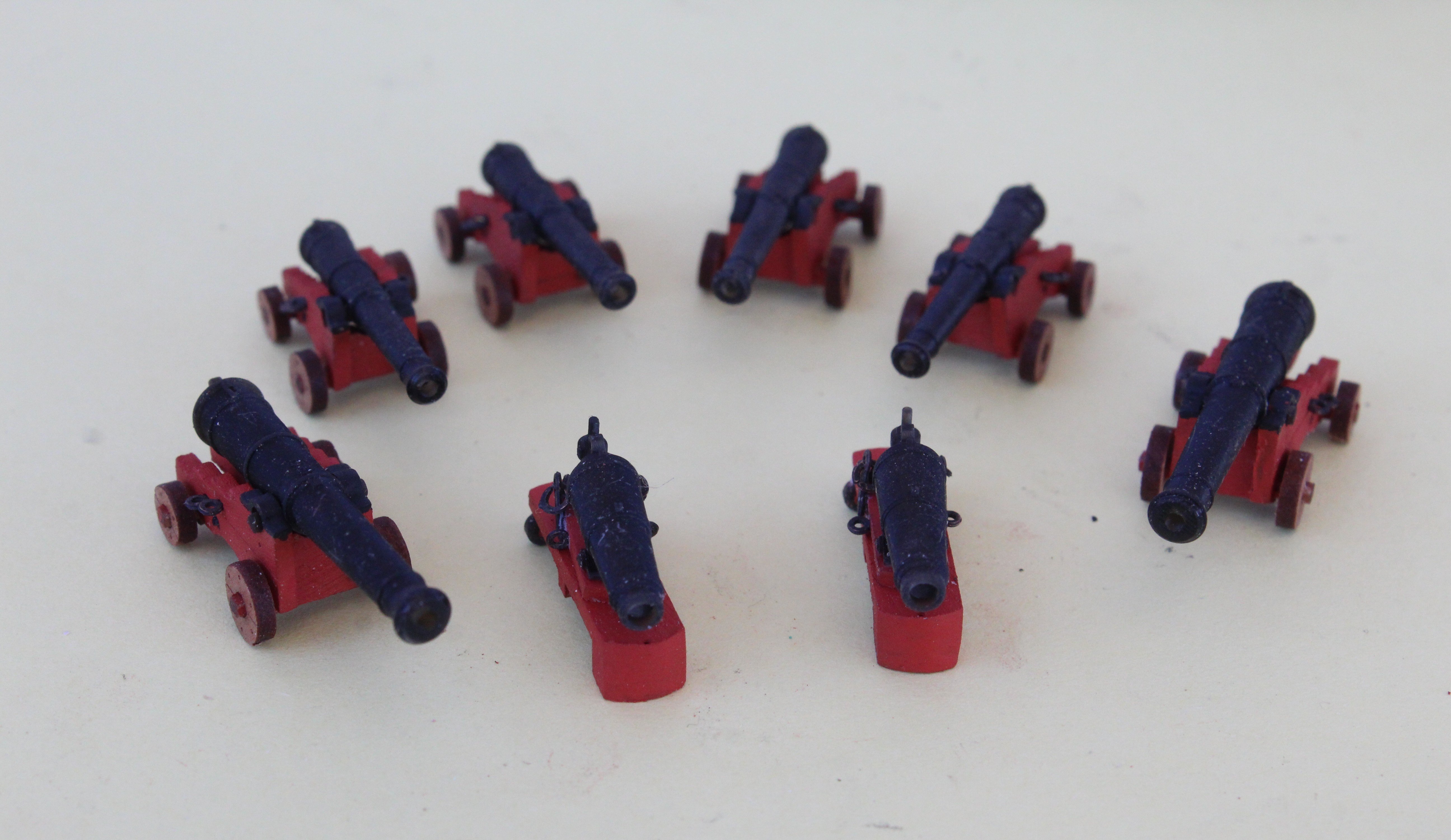
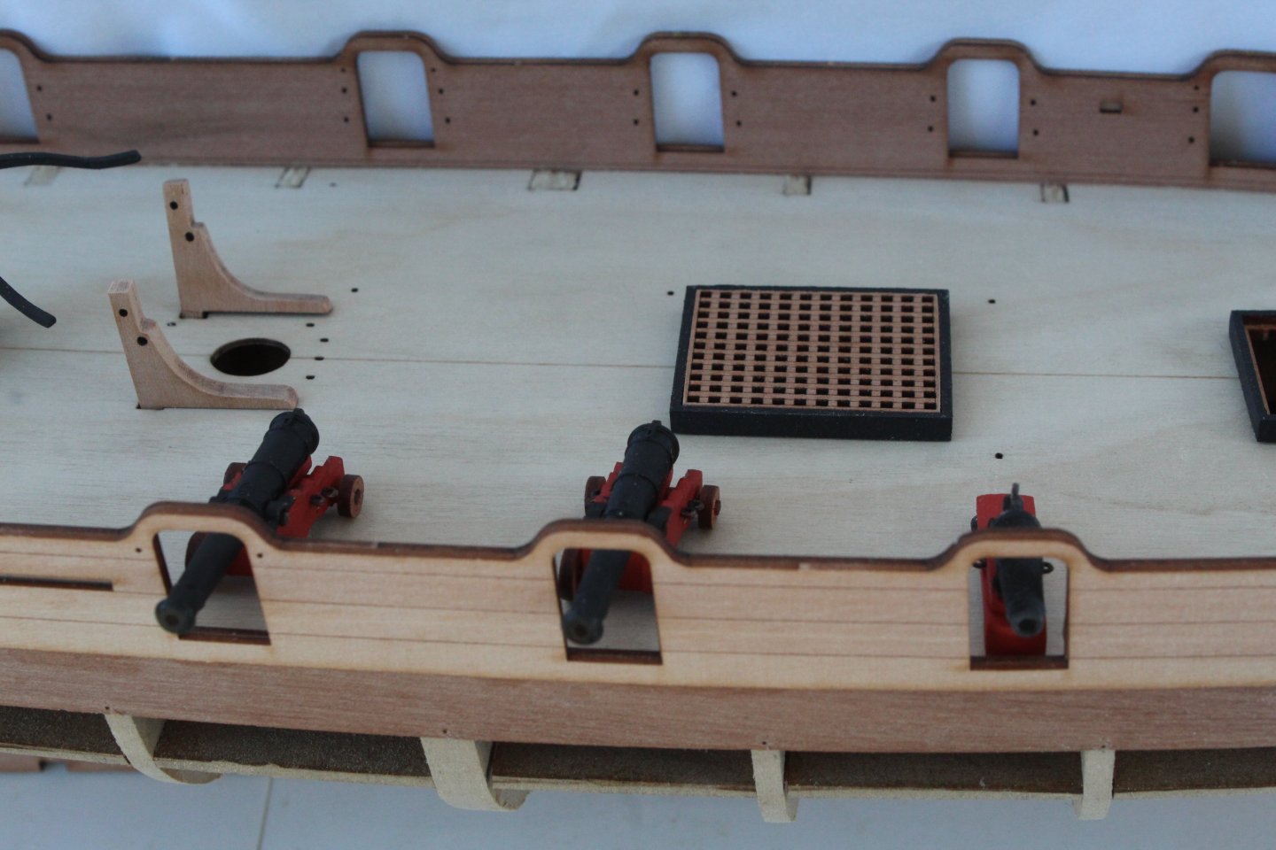
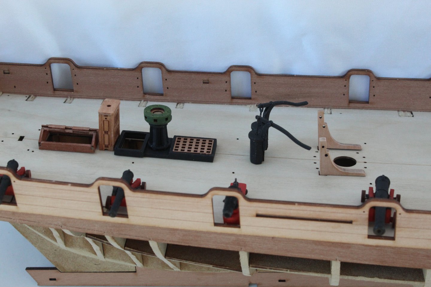
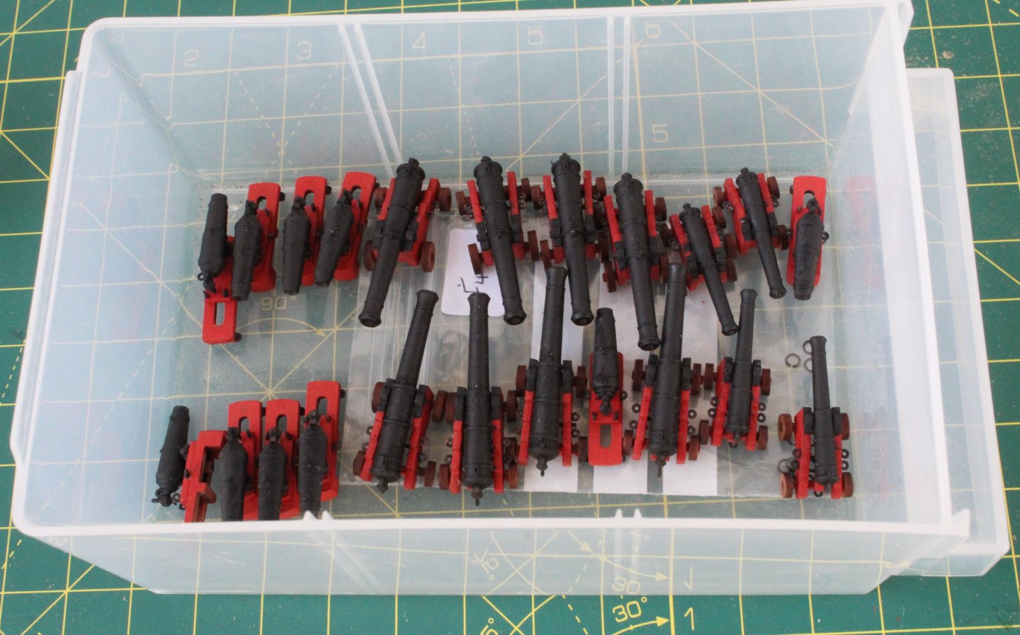
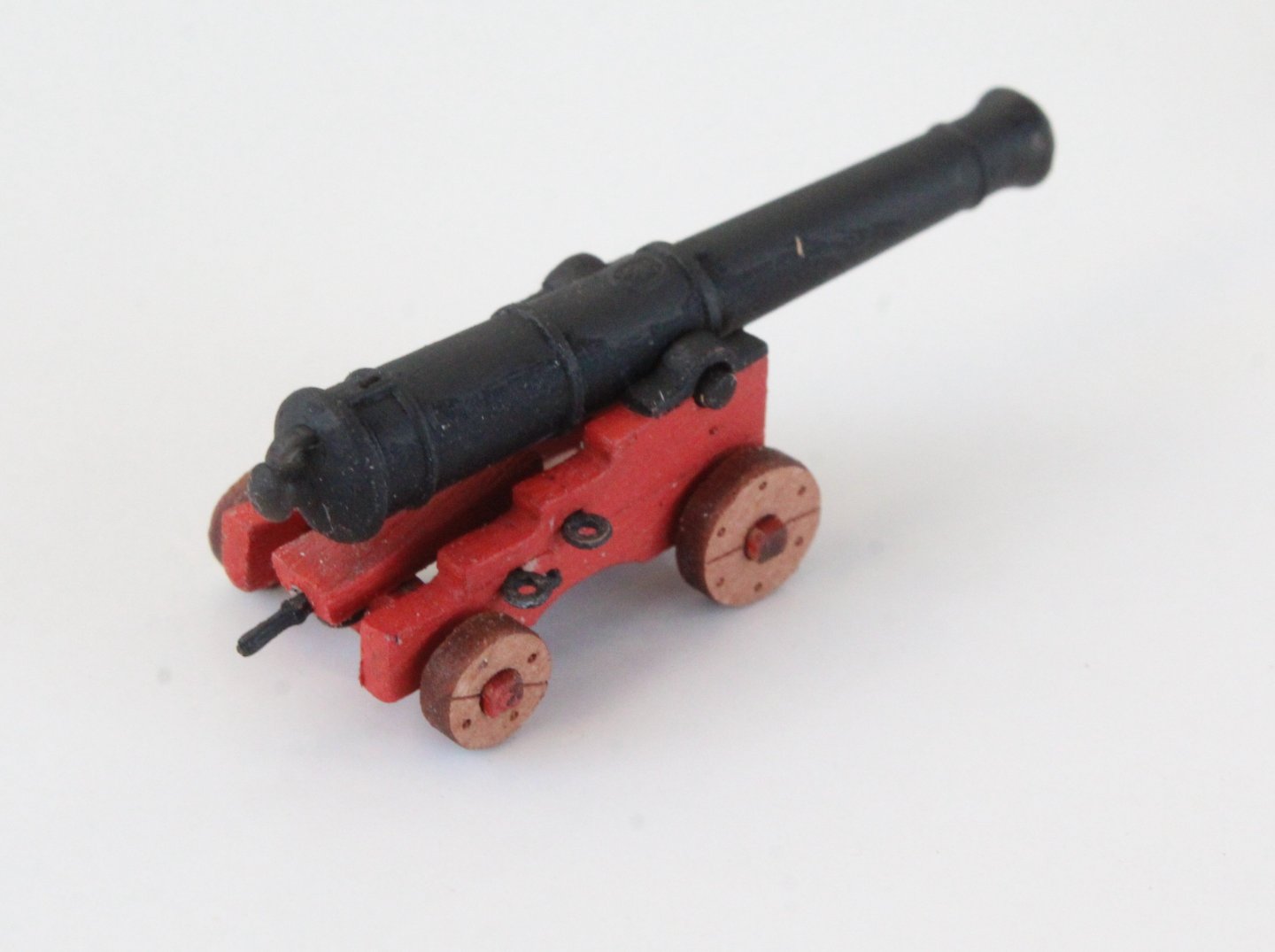
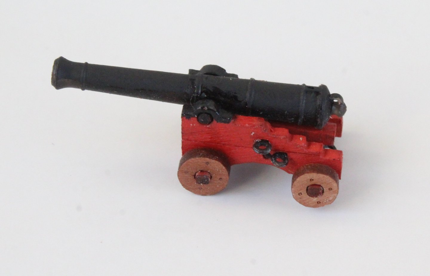
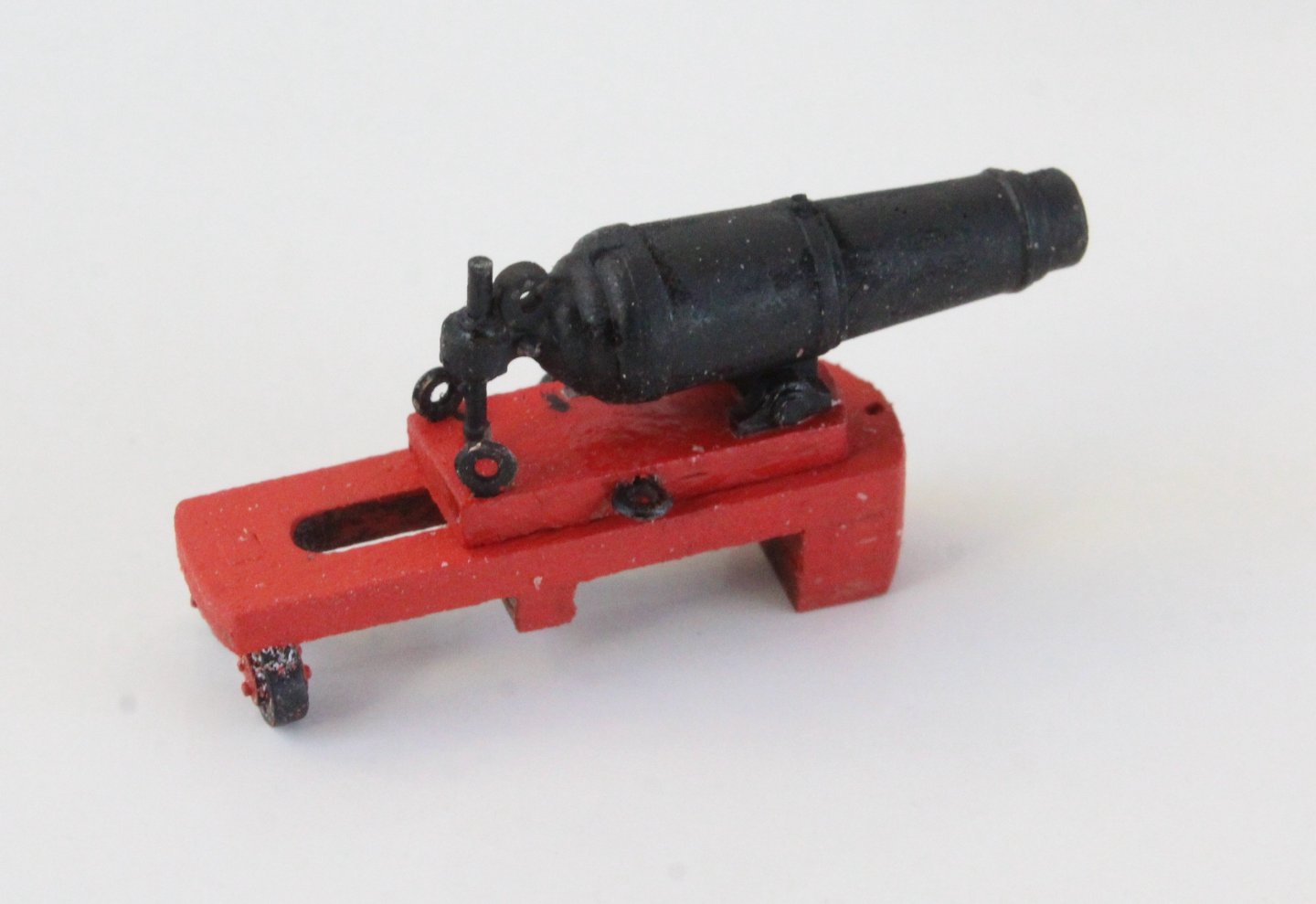
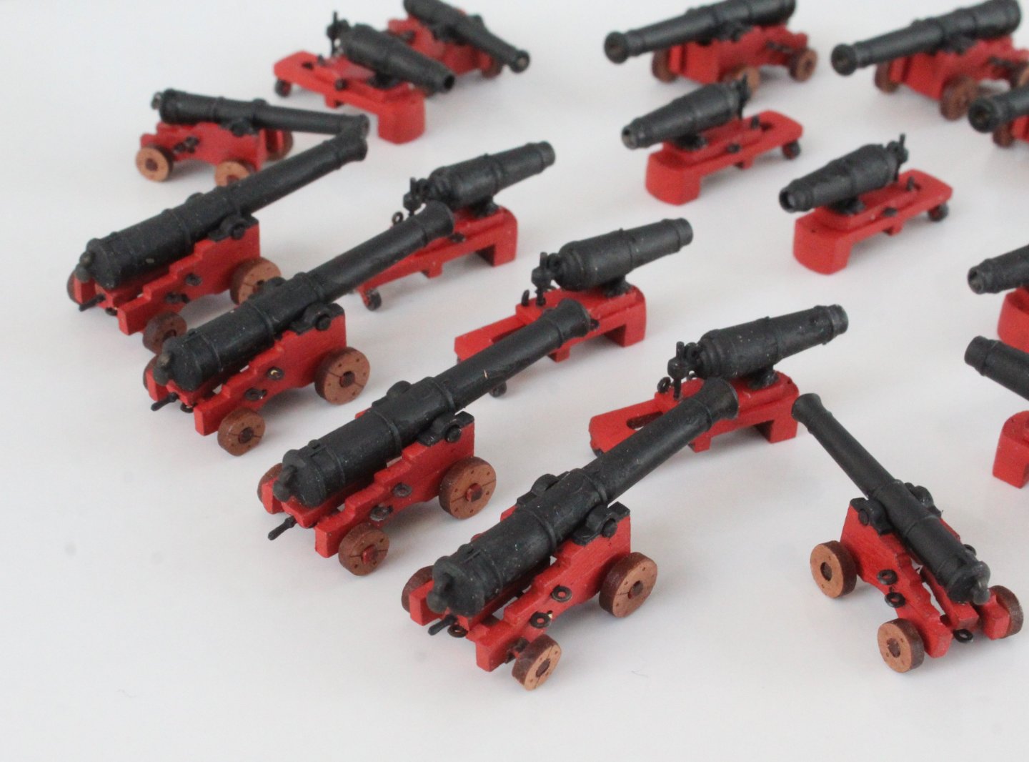
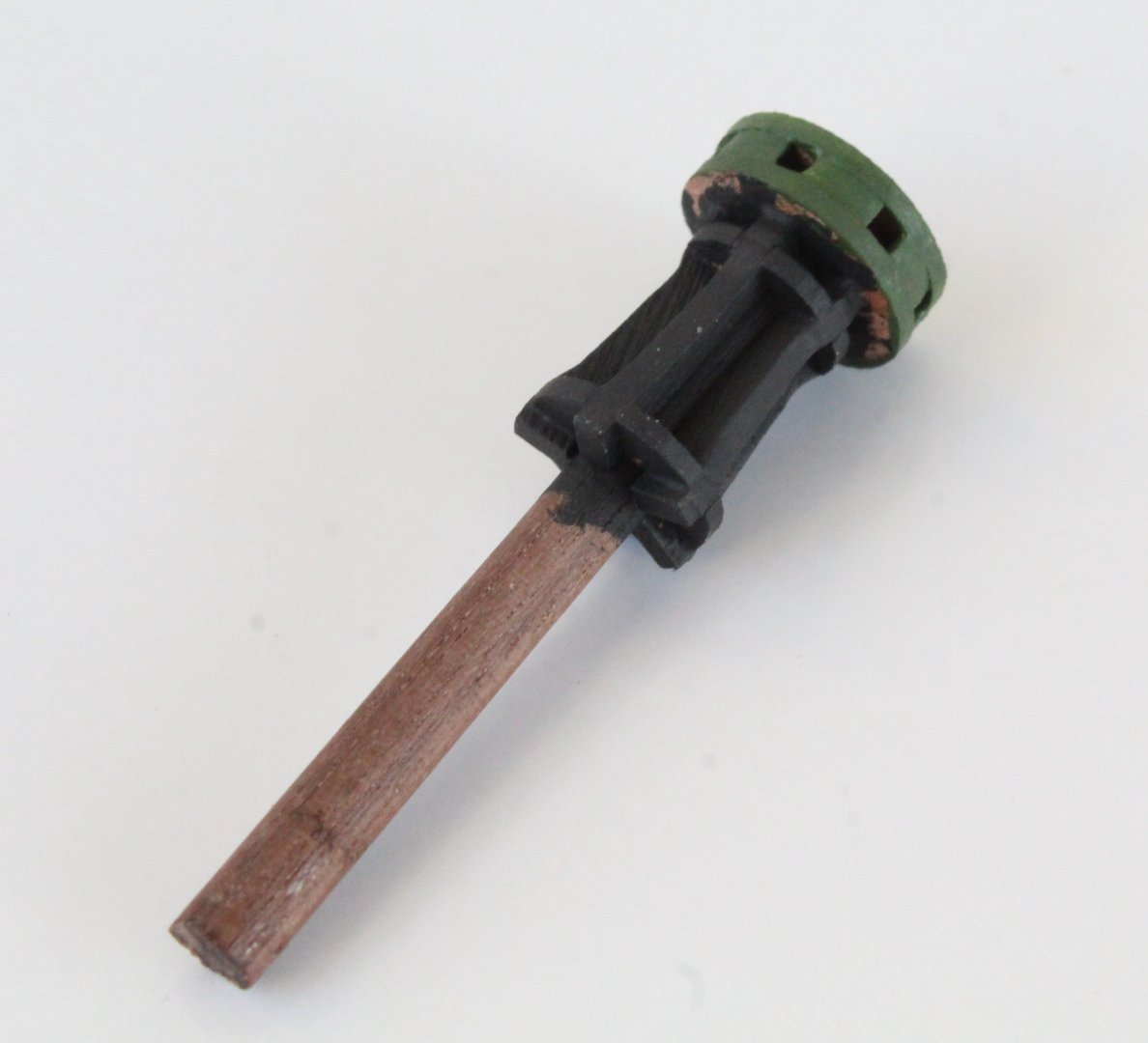
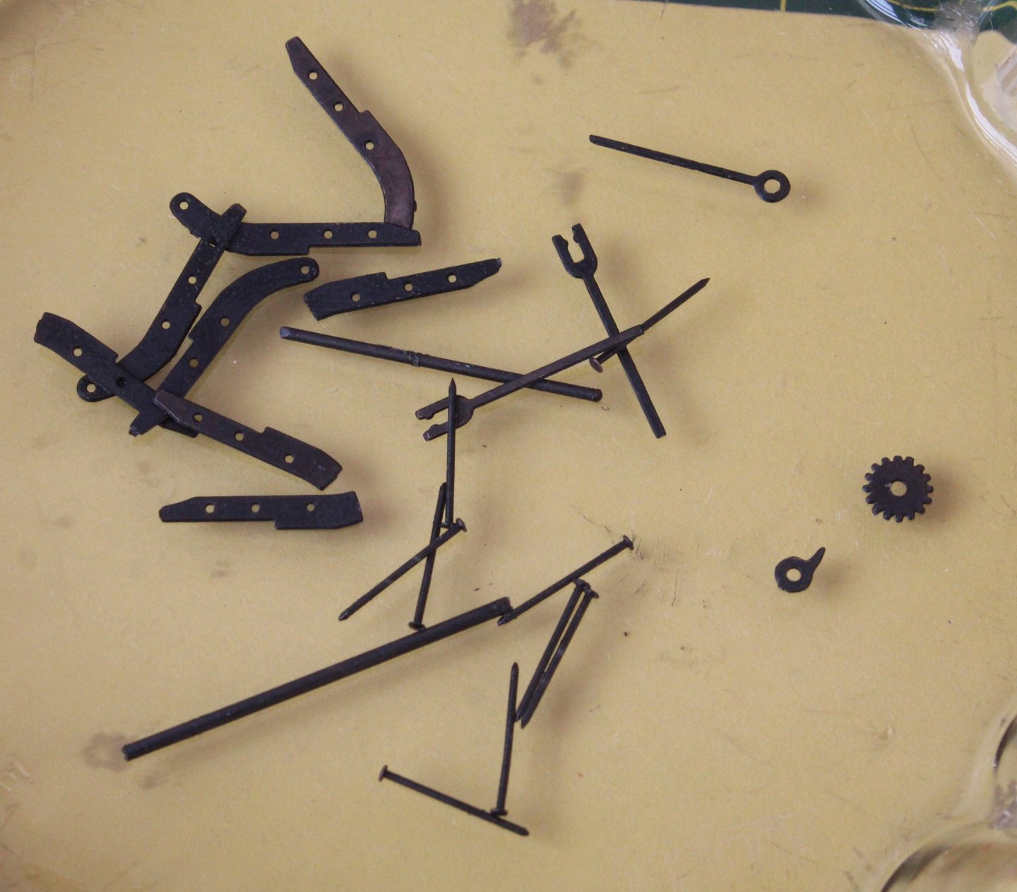
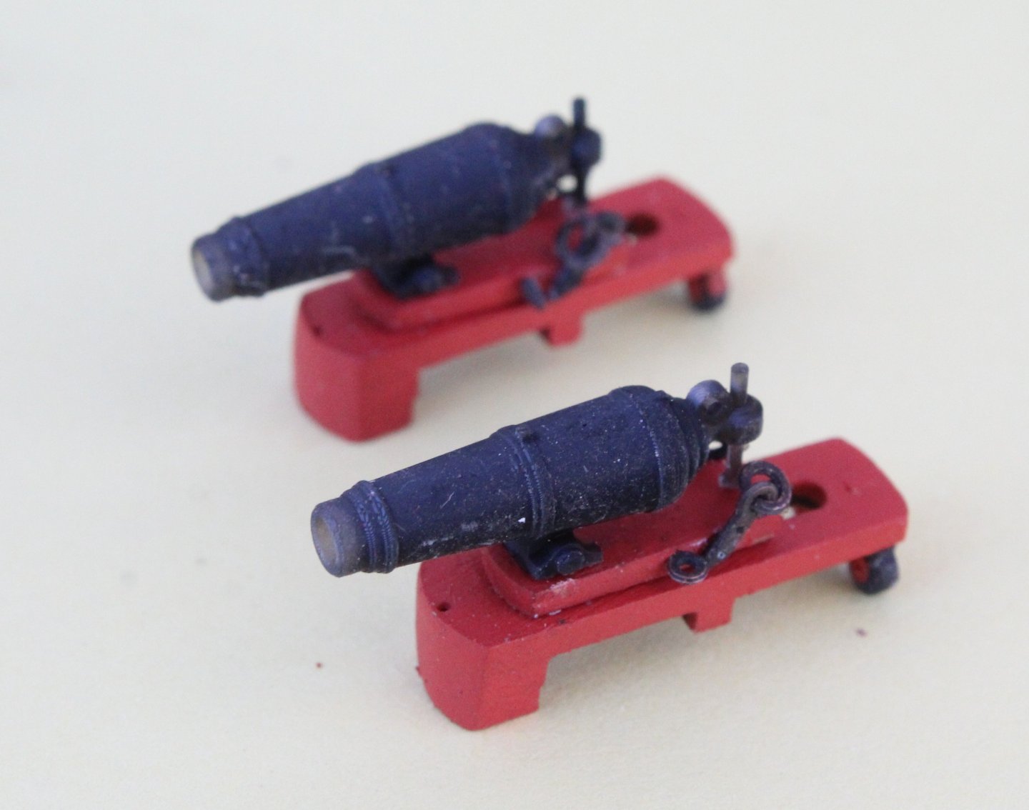
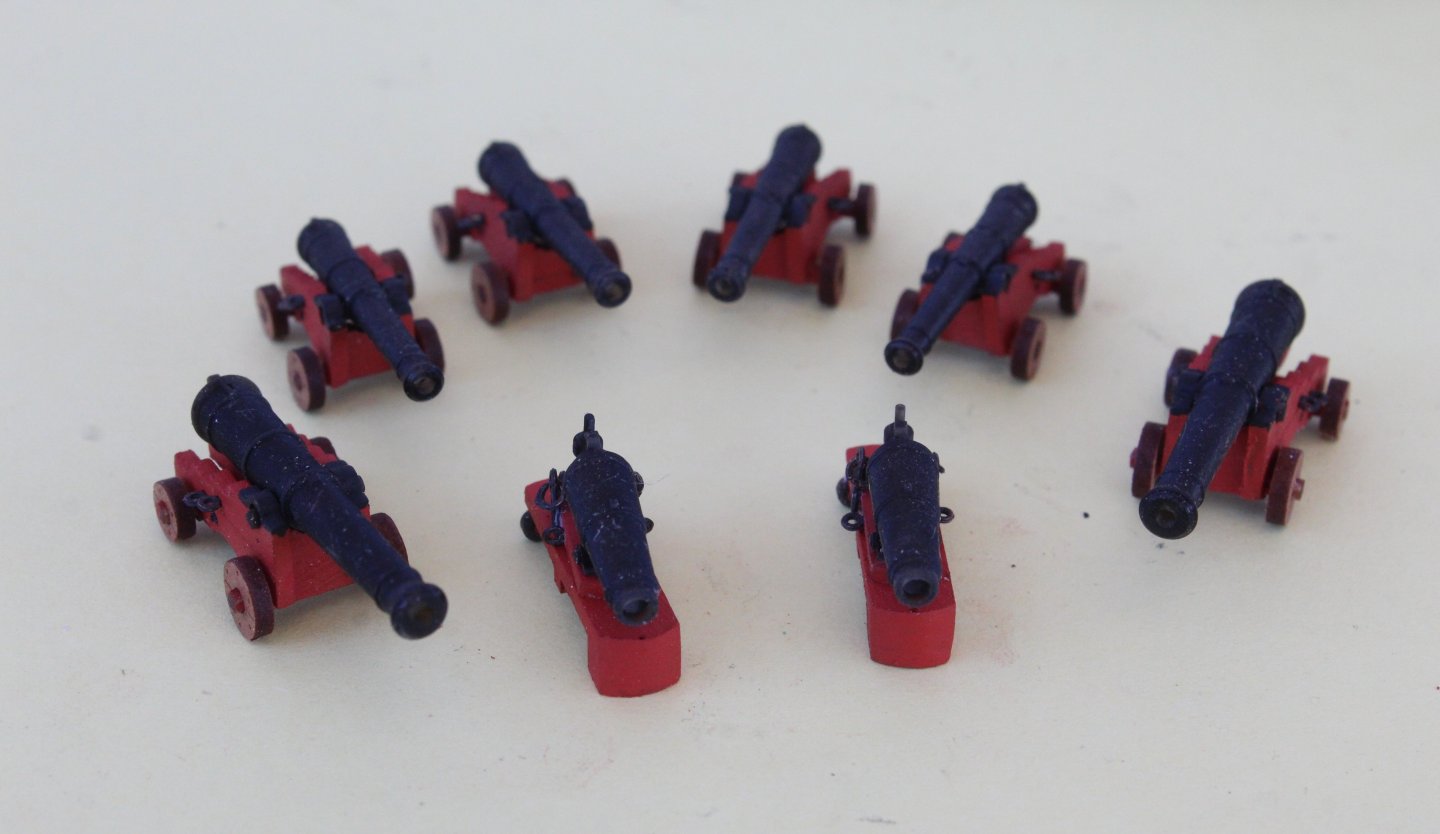
I have now completed assembling the various armaments. In the end I have made 8 x 6 pounder cannons, 4 x 4 pounder cannons and 8 x 18 pounder carronades. I do have another 2 partially built 18 pounder carronades which I will complete. I did end up removing the carronade ringbolt straps and ringbolts from the carronades as I thought they looked a bit chunky and did have a tendency to fall off at the slightest touch. I have not found a reliable method for aligning and securing the carronade ringbolt straps and ringbolts to the sides of the carronade gun carriage. 1 x 6 pounder cannon. I will probably add breaching rings to the appropriate side eyebolts. I used some spare belaying pins for the handle on the carriage quoin noting it is a bit oversized. 1 x 4 pounder cannon I will probably add breaching rings to the appropriate side eyebolts. 1 x 18 pounder carronade The complete set of armaments I have also painted the frames of the various hatches black. The capstans has also been painted. At the moment I have painted the top section green but I might opt to use a different colour. The underside has not been painted as this area is not visible once installed. The catheads have also been painted. I might add some embellishments to the side engravings and end caps at a later stage. The two hand pumps wooden parts have been painted are are now ready be assembled with the PE parts. I also now have an option to build and try out the Syren Elm Tree pumps which will be a side build project at some point in the future. The ships wheel drum has been painted black. It will require a gentle sanding to removed some of the rough edges. I also now have an option to build and try out the Syren ships wheel which will be a side build project at some point in the future. Finally, for this post, the Syren serving machine has arrived. I have removed the laser char and assembled the basic frame, as shown below. I have also assembled the four wooden cogs and operating handle. This project is now on the back burner. Now that I have completed building much of the deck items I will now start to build the hull, but this will have to wait a couple of days due to grandparent duties.


-
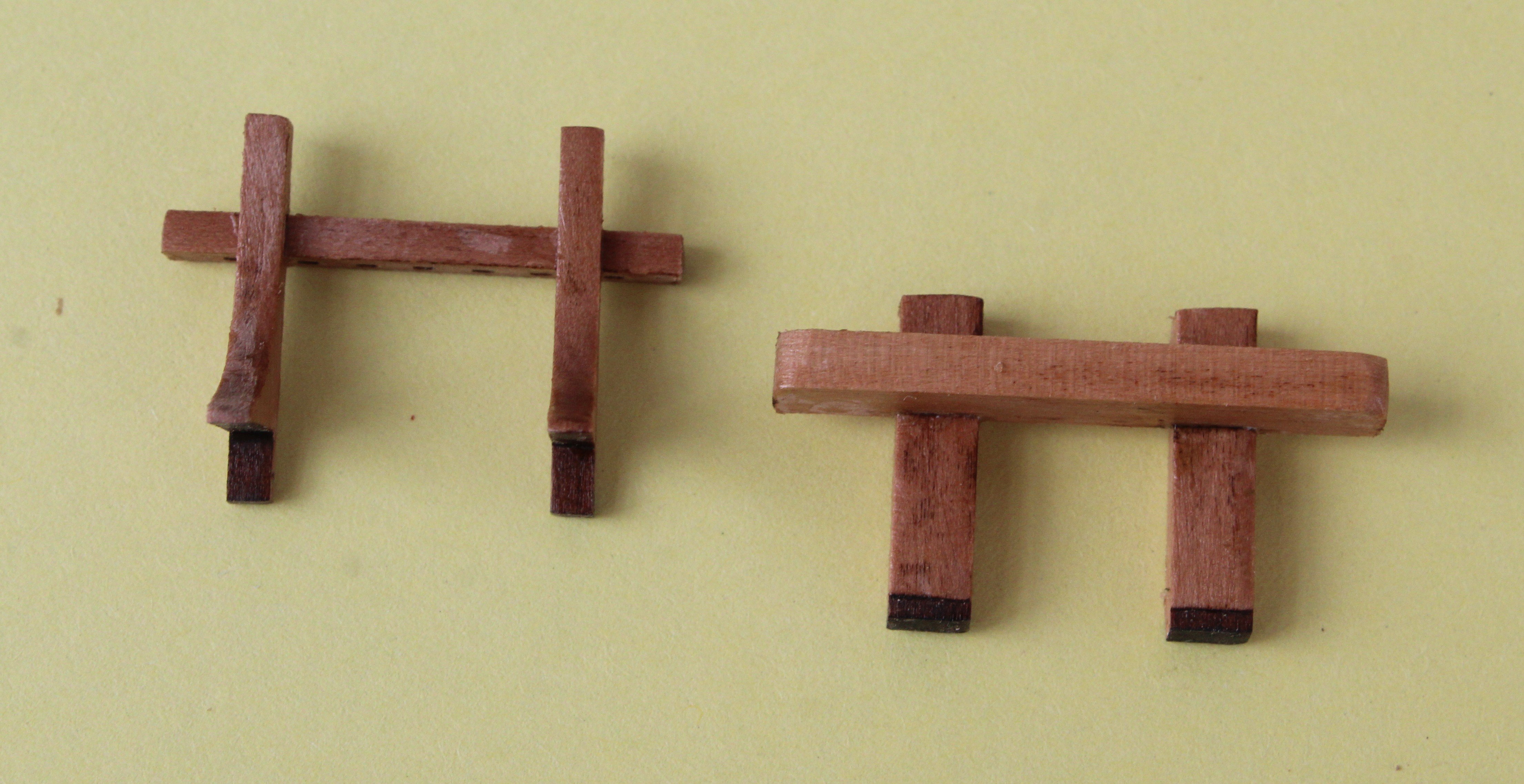
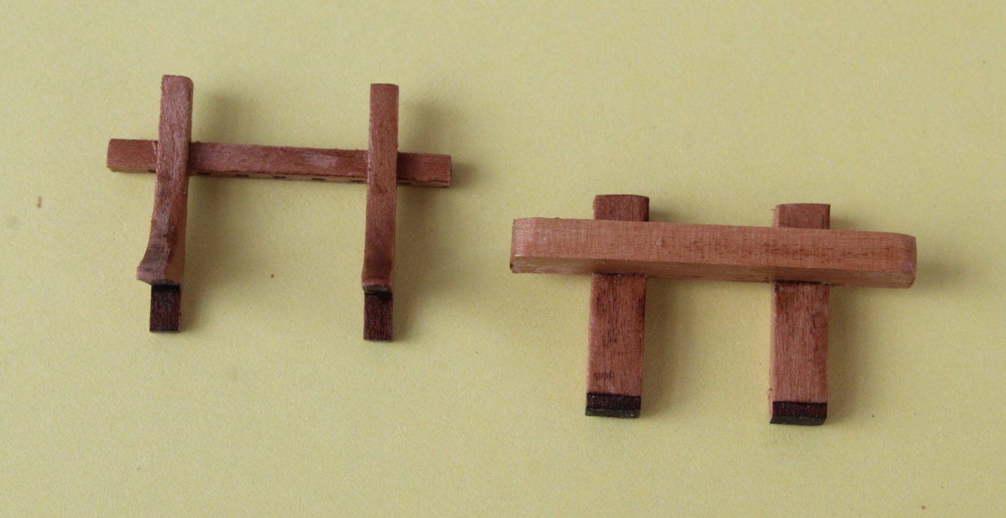
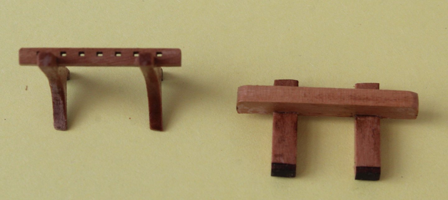
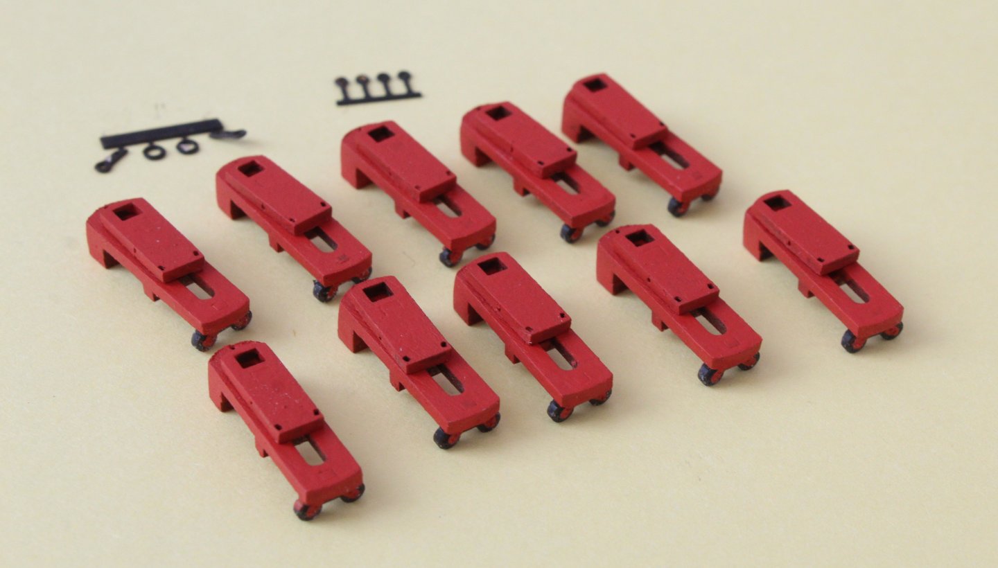
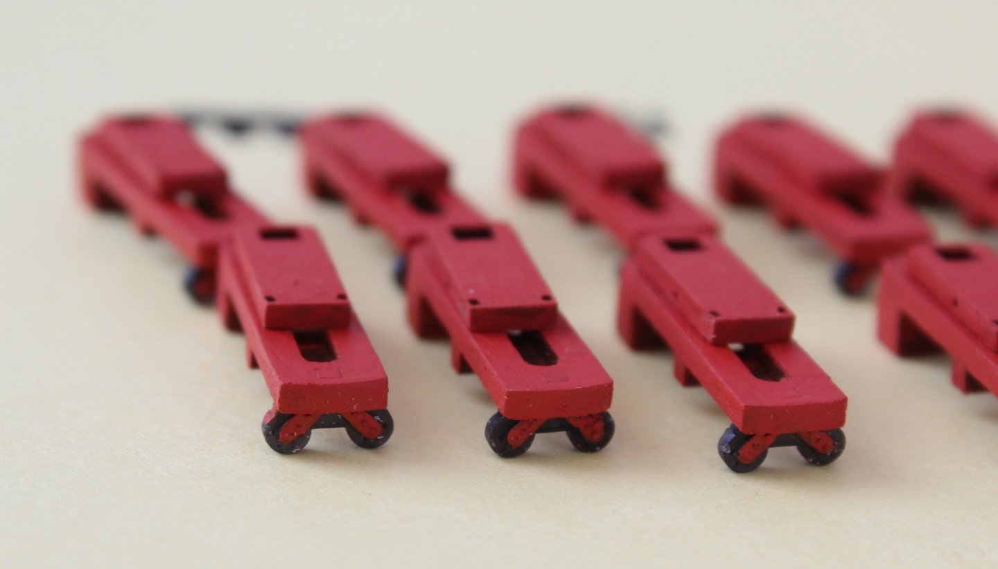
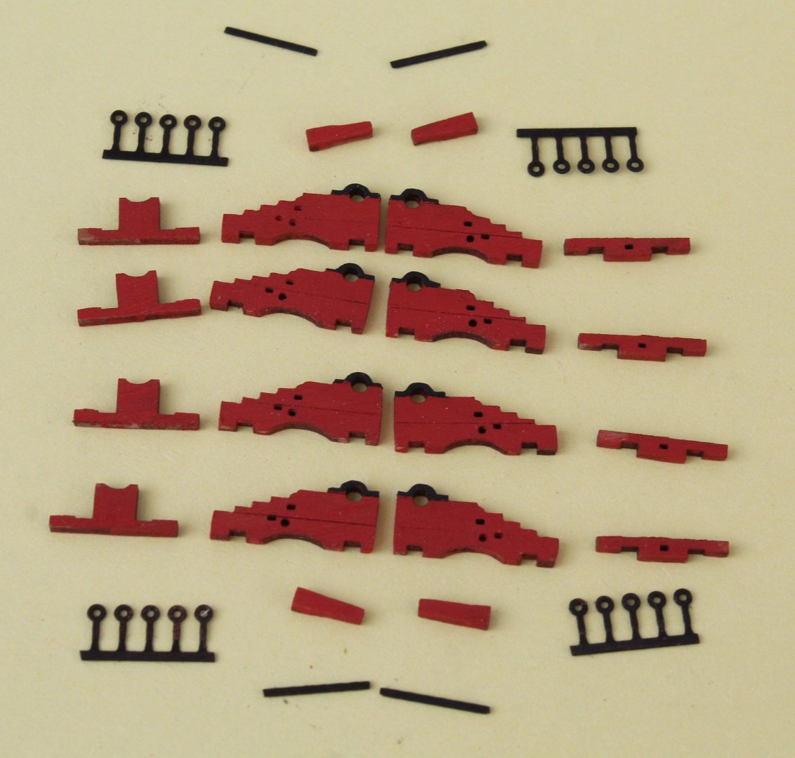
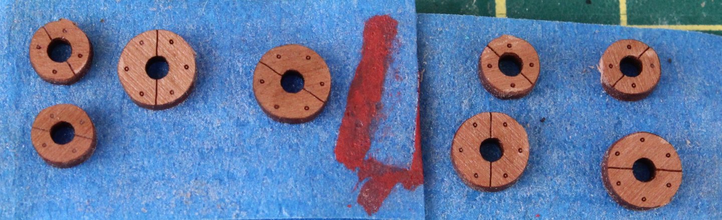
I have been making some more deck items. The first two photos show the WIP on the two hand pumps. All the PE parts have been chemically blackened. The hand pump wooden assemblies have been glued together. All that is left to do it to add the PE parts. I have ordered two elm pumps from Syren so I am waiting for that to arrive before proceeding any further. I have also assembled the two bitts. I am currently making the various armaments, which consist of 18 pounder carronades, 6 pounder cannons and 4 pounder cannons. The build manual does detail the armaments fitted as follows: US Privateer, Grecian was fitted with only 2 x 6 Pounder and 2 x 4 Pounder carriage guns Royal Navy service Grecian was fitted with 8 x 18 Pounder carronades and 2 x 6 Pounders carriage guns Pictures in build manual was fitted with 12 x 18 Pounder carronades, 2 x 6 Pounders and 2 x Pounder carriage guns I am unsure what combination of armaments I will use for this model. I started to assembly 10 off 18 pounder carronades. As shown in the photo below the carriages have been painted and assembled and they just waiting the PE parts and the 18 pound carronade barrels to be added. I took great care with painting the 18 pounder carronade wheels, as can been seen below. 4 off 4 and 2 off 6 pounder cannon carriages have been painted red and the PE parts blackened. The carriage wheels are also ready be added. The first two 18 pounder carronades have now been assembled. I have also built 2 x 6 pounder and 4 x 4 pounder carriage guns. I have added the carronade ringbolt straps and ringbolts but as they have a tendency to fall off I am not sure if I will use them for this model.


-
It will slow down when I start working on the hull😀