DONATION DRIVE - SUPPORT MSW - DO YOUR PART TO KEEP THIS GREAT FORUM GOING!
×


milosmail
-
Posts
90 -
Joined
-
Last visited
Content Type
Profiles
Forums
Gallery
Events
Everything posted by milosmail
-
Currently convinced model ship builders are all OCD, myself included. I am in the midst of attaching 60 rings to 60 small eyebolts for the breech line and inhaul. Very repetitive, very tiny parts, very boring.... Only thing worse (maybe) is tying the ratlines to all the shrouds.....🙃😄😉
-
Thanks. I did try some small ball heads, but the wood didn't seem to want to cut cleanly - maybe because the kit was purchased over 20 years ago and the wood was too dry. It seemed to shred rather than come off neatly. However, all's well that ends well. An aside: I bought the kit in 1997 or so, having built the Mantua Ironside cross section. When I received the kit and read the manual, I knew I was in over my head! This is not a beginners kit... I spent the next 18 years building a few simpler kits, purchased some tools, and I purchased two of Bob Hunt's invaluable practicums to learn technique and improve skills. Started on the kit in 2018, with some stops and restarts along the way. I think I'm a journeyman builder now which works for Niagara - a kit where most pieces need to be shaped by the builder and plans are very detailed (but instructions are not). I would call this an intermediate kit, as it doesn't need any intricate carving and detail, which is seen in construction by many of our expert builders.
-
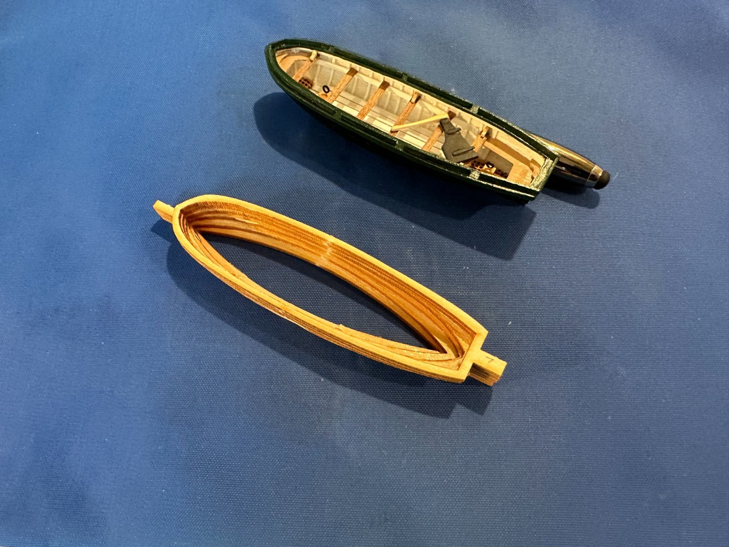
I decided to take a break from deck work this summer and build (actually finish) the cutter. As I mentioned before, I am only building and detailing one, and I plan to position it over the main grate area, more or less. I think this is a more likely position historically - based on no real knowledge. I will build the yawl in the future, but I plan to simulate a sail cover, so I won't be detailing. I started on this item about 3 years ago when I glued up the pieces and shaped the exterior. Very straightforward. But when it came to shaping the interior, I found this a real challenge. I tried using my Dremel, but could not find a tip that would allow the detailed shaping I needed. I consulted several articles in NRG and other modelers builds, but they all seemed to say the same - just carve and sand the interior, whithout actually explaining how to carve it cleanly. I tried various types of chisels without much success until I purchased a set from Micromark. I also found a reference that said to finish the detail smoothing with putty (I used Tamiya putty thinned down a bit). This made quick work of the process which had kept me from advancing for a loooong time. I learned I could make the ribs and floorboards from strip plastic, and the rest of the interior such as stern and bow sheets from basswood sheet (copying the plans for templates) plus mahogony strip for thwarts. I separated the rudder from the keel, made a tiller, and laid it inside after completing painting. I left out the oars, as I felt it would just clutter up the interior. The hull is the same black as the ship's hull with green trim using the same color again as on the hull. I'm happy with the results, and it was an excellent learning experience. Meanwhile, I have built all the deck furniture from cathead to rudder/tiller, plus the bowsprit. So, no more stalling - next week I will start installing cannon.

-
OK, all finished! I built the skiff in a few days/weeks/months/years - depending how you want to count. Once I solved all construction problems, I built it in a couple of months; working an hour most days except for vacations and resulting severe cold (ha). Lots of time went to waiting for glue or paint to dry. Attached is a photo of the finished product, sans oars which I felt would just clutter it up.

-
Thanks for all the encouragement. I came up with another solution based on your suggestions. I used the billet E as a stencil, using the top component as the best shape. This would be the piece directly under the caprail. I was able to enlarge it slightly, and then - using my compass as suggested by Toni (tlevine), I created a 1/8 in. wide caprail. This accurately created an even/mirror image shape and width as originally planned, and hid my minor irregularties. I also found it MUCH easier to deal with the 1/32 basswood, which arrived 3 weeks late from the seller. Once the caprail is on, I will add the fender to the hull. Originally I tried cutting from birch ply, but that was a disaster, and I think it spooked me. I will post my solution on my build log, along with photos of the finished skiff (cutter), one of these days. PS: I plan to build the yawl with a cover, and do not plan to finish the interior. But, given how easy this went, I will include a fender and caprail.
-
Realy nice work! I'm about ready to start with rigging, but I have spent the past month to interrupt workflow by building ships boats. Have you built yours yet? I am not sure how to build a caprail for them. Any ideas would be appreciated. The rest has been pretty straight forward; used styrene strip for most of the detail, and birch for seats and the two sheets at bow and stern. Debating how to make elbows....or just leave off.
-
I have been working on the cutter for my MS model of the Niagara. It is progressing well, but I have met one obstacle - how to construct a caprail. Kit did not provide this piece, and I can't figure out how to construct except from perhaps a flat sheet of thin wood. The caprail takes a very pronounced curve at the bow. It is not feasable to make this by bending a strip of wood (or, at least I don't know how), and making a quality caprail by cutout from sheet wood is beyond my skill level. I will have the same problem with the yawl/stern boat. So, I am looking for advice from those who built these before.
-
Here are a couple of photos of the binnacle mentioned earlier. This one is 1:64 scale sold by Crafty Sailor, manufactured by Falkonet. It was a simple kit with well fitting parts - mahogany I believe with a brass machined lantern stack. The interior cross brace piece below the windows has a print of a couple of compasses on it. As I discussed, I can't imagine in 1812 they sailed without one, even if they stayed within sight of land (?). And the current Niagara has a binnacle roughly where the model has placed the captain's skylight. At least that is what I see in the photo in my Spring issue of Sea History (it was an ad for a 2 week cruise on the Niagara this summer). No sign of a captains skylight, but it may just have been out of the picture. Anyway, I'm going to place my binnacle just forward of the tiller, and leave the captain's skylight off. Comments?
-
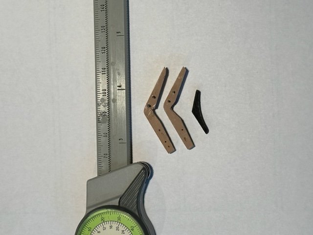
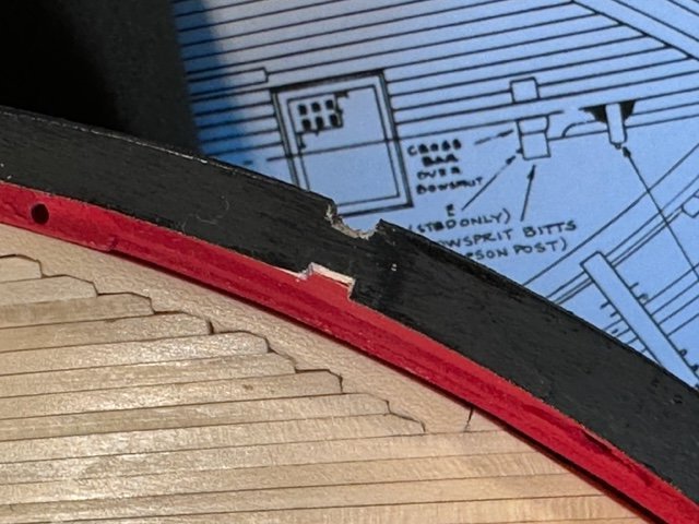
I have been working on the catheads. As many previous modelers have mentioned, the catheads supplied with the kit are not shaped accurately, in that the acute angle where the part arches over the bulkhead is not severe enough to properly meet the bulkhead and also arch over the side without leaving a large gap at the cap rail. This part should rise up the ceiling in contact with the interior bulkhead planking, and then bend such that it fits flush on the caprail. Without a modification, the knee below the caprail will also not fit properly, and the whole unit will not provide sufficient clearance for the anchor. I reviewed what several modelers did, along with their photos (search on Niagara caphead), and decided to severely notch the bottom portion of the cathead which arches out over the hull. To get a good fit, I also notched out a piece of cap rail and the top plank on the bulkhead, thus permitting a clean installation of both pieces. Caution: be sure to properly support the cathead. I snapped one in to at the bend, and had to repair with CA. See photos attached. The cathead on the left in the photo is unmodified. The one on the right has been 'shaved' and now meets the interior bulkhead and knee properly. Other modelers have taken different solutions. I suggest any future builder review all and make their own choice on how to proceed. PS: I also reviewed several actual catheads on 18th. and 19th. century ships for which I found photos. Everyone seemed to do it differently, but mostly they just stuck a large beam out through the bulkhead.
-
Top notch work. I enjoy the read, as I am about 3 months behind you. I should be into the eybolt/block business shortly.
-
Question of general interest. The model has no binnacle. Yet, the current ship at Lake Erie has a binnacle with navigation and engine/elecrical controls just forward of the tiller - roughly where the captains cabin skylght on the model is located (based on the photo I saw). So, is there really a skylight there, and/or why is there no binnacle on the model? I know binnacles of yore were portable, but with the skylight and then the companionway installed, there would have been no room for a binnacle. By the way, Crafty Sailor sells a binnacle cabinet at the 1:64 scale so I went ahead and bought one. Nice quality small kit.
-
I fnd it surprising there are so many sheaves running through the wood. I wonder if this is true to the way the current ship is built. Each 'hole' in the wooden mast/spar weakens it a bit. Modern ships hardware includes a variety of sheaves that can be firmly attached to a mast, and would be used. Also, with time, sheaves occasionally wear out. Simpler to replace an attached sheave than one imbedded in a mast. Then there are the sheets running through the bulwarks. I'm pretty sure that the original Niagara did not have sheets running through the bulwarks as there is a great deal of tension on these lines when in use on a given tack and a tendency to pull out the railing. By the way, I used bullseyes to simulate the sheaves for these four points in the railing. Worked well. Enjoying your posts, thanks.
-
Very nice work. I just finished the bowsprit, etc. and find myself ready to install all the deck fittings. I'm going to buy the hooks from Crafty Sailor as that looks to be a major time saver. I just tried my hand for the first time at silver soldering, with success. I was a bit nervous, but found it simple to do. I made the bobstay ring and added the metal strop using a brass eyebolt. Easy peasy to do, so I will follow your path in making the other parts. I have a couple of 3 hand units from MicroMark that I used to hold the parts in position, which worked well. Incidentally, on what to do (or what is done) with the tiller line: I saw a photo of the deck at the stern while the ship was recently under sail. There is an additional jam block on the tiller which secures the line. Jam blocks did not exist in 1812, so I'm sure they did what you mentioned. Just anything that allowed the tiller lines to be quickly adjusted in an emergency... I also like the appearance of the stain you applied to the dowels, and I plan to follow suit as it looks more natural. Your blog has been a great help to me, especially warning me of 'gotcha's' and solutions to design problems. Thanks for your help.
-
Thought I would post a bit about my bowsprit construction findings. From examining the plans, it looked complex (and challenging). But it turned out to be mostly straight forward. I am fortunate enough to own a Byrnes saw, so it was very easy to shave the square 3/8 dowel down to plan size of 21/64 on a side. I think a lot of other Niagara builders have either tried to sand down or left it at 3/8. Having done that (the easy part) I took a closer look at the details. First, I made a copy of the top and side views from the plans, cut them out and attached with 2 sided tape to the square dowel. It is important to realize the top of the bowsprit is flat and needs no shaping. Additionally, while the bottom appears curved, it is actually 3 straight sections. Sides do taper, but this doesn't start until outboard of the square section which passes through the hull and the octagon outboard of this section. So, it's not as complex as it looks. Rounding the barrel section can be done with a fine bastard, and it only took me about 15 minutes as this wood is very soft. After I finished shaping, I added the tenon at each end and shaped the bowsprit cap which were quick work. I made bees, but held off installing till I made the bobstay hoop. The kit did not include the necessary brass strip to make the bobstay, but I had spare. Shaping into an octagon was a bit tedious, and I left a small vertical tab on the bottom to attach the strop needed later for the bobstay. I made the strop from a large brass eyebolt on which I bent the straight end to grasp this tab on the hoop. Then i soldered these together (my first try at silver soldering - success!). I have a nice bar on the hoop now to which I can attach the bobstay blocks eventually. Finally I added all the chocks, treads, and cleats. It's ready to paint now, Hooray. Footnote- I wish the instructions or previous builders had mentioned that the two cleats need to be added AFTER the bowsprit is attached to the deck. It won't fit through the hole in the bow with cleats attached.
-
Niagara by Alex-Ks1 - 1:7 Scale
milosmail replied to Alex-Ks1's topic in - Build logs for subjects built 1801 - 1850
I just found this build log. Marvelous and fascinating idea. There are a zillion details on the plan that are nearly impossible to replicate at the scale of the kit. I wish you a speedy recovery and good health! -
Hi Steven, I did make make replicas of the metal plates out of stiff paper. I made a template from the plans (which are not exact), and then I used Photoshop to replicate it multiple times on a photo drawing. First I blackened the back side with felt pen to simplify painting, and then I cut them out with a #11 blade. It only took a few minutes. I poked a pin through each plate, put a dab of CA on each carrage, and using the pin as a guide I was able to quickly position the plate properly. After glue dried, I painted the top of the pin black, and cut the pin down to fit the hole in the planksheer. Other people have either handpainted a black strip for the plate or manufactured from brass. My process was quick to replicate, and at the scale of the kit, I think it looked accurate. See photos in one of my posts. Your work is looking great. I wish I had the time to work at your pace. I am currently making more deck odds and ends - pin rails, channels, fife rails, and the catheads. My power tools are in my garage, and it's too cold out there to work (I know, people in California don't know what cold is). So I am working on items I can make at my bench indoors. I have a new Proxon DB250 lathe which I plan to try on the bowsprit when temps. rise a bit.
-
I'm about to begin work on the bowsprit, and I discovered that the square dowel - at 3/8 - is slightly larger than the plans call for. So, is it really worth sanding off 3/64in. to reach the desired cross section. What have other Niagara builders done? Also, Steven, did you round the square stock, and then shave off a bit of wood to flatten the top? This seems to be my next major challenge on this kit.
-
I am at the point of installing the deck permanently, along with the furniture and cannon. Rudder will go on as well. I have decided to install only one cabin, although I built all three. I suspect (with no authority) that the original ship had only one, if even that. I originally thought the cabins would interfere with actual use of the windlass, but I have seen models of several other ships in this perriod where the windlass likewise was very near a cabin. I can only assume that, by using long poles, crew were able to circle without interference. Also, the tiller... Is the tiller on the current ship reinforced, or does it have a power assist below decks? My sailing experience in strong winds says that such a narrow pole as found on the model would break like a twig, especially with the blocks providing 2 or 3x purchasing power. At any rate, I plan to place a metal band at the top of the rudder post, and another where the blocks attach to the tiller. I'm nearly to that point where I can start mast/bowsprit construction. I splurged, and purchased a Preacc wood lathe to shape these parts. I'm looking forward to trying it out. The bowsprit looks to be quite a complex piece, what with all the differrent surfaces and fitting. I'm looking forward to it.
-
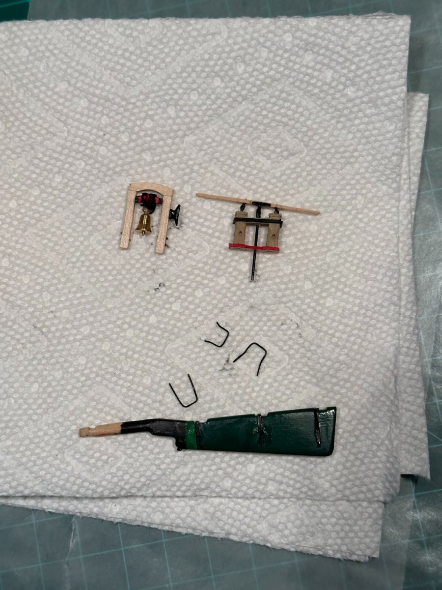
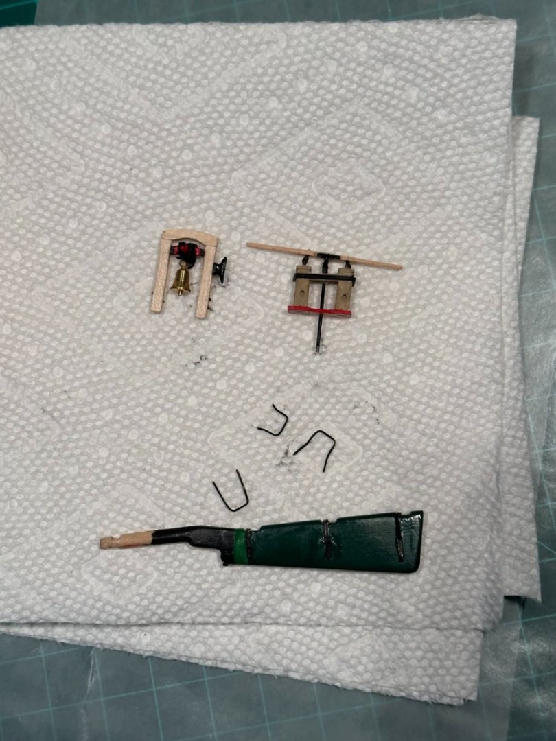
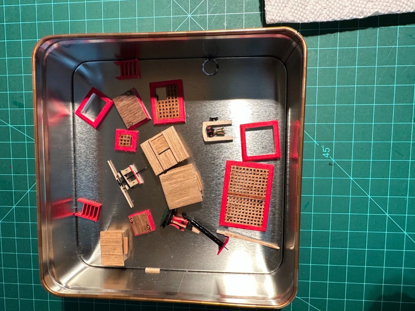
Quick update: I have been muddling along since my last post in September. I have assembled the various pieces of deck furniture, and finished off the rudder - which was more of a project than expected. I will hold off installing it till I finish with exterior fittings (mounting points for various items, etc.) Furniture was uneventful, except for the (*^&^%$%) bell. I had to build this simple assembly three times, and mounting the bell was a real challenge. Why couldn't they supply one with stirrup at the top. I didn't have the tools to dril a hole, but I finally got an acceptable piece by judicious use of thread and super glue.. I thought the pump would be the big challenge, but it turned out to be very simple; using plastic strip for the 'metal' bands simplified the whole thing. I'm on to drilling holes for the gun tackle. I built the jig created by 6ohiocav in his build. Makes the process of drilling over 100 holes for 18 guns a simple and quick process. Speaking of gun (ports), why are there two on the stern? And, did they really exist? Any gun rig in that location would have greatly interferred with use of the tiller. I notice the plans do not include any indication of gun tackle there. Anyone know why the modern Niagara has these ports? I'm not sure I'm going to rig all the carronades. I will put a breech line on each unit, fully rig a couple, and the cannons as well. Still debating if I want to rig them all. So much for accuracy on my part. But then, it's MY Niagara... I will post some pictures shortly. Well, back to installing eyebolts....
-
looking good...
-
Thanks, Eric. I try (boy do I try). Sometimes I have to build the same thing several times to get it right. But, I'm not in a hurry.
-
Thanks, Tom. I did not intend to imply that mine would be historically accurate, as I am not qualified in any way to say what is 'authentic'. I know this can be a touchy subject with some folks. What I said was only in the way of discussing what I plan to do (right or wrong), and maybe get some feedback from those who might know more.
-
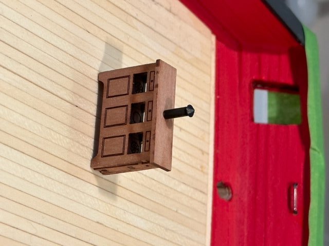
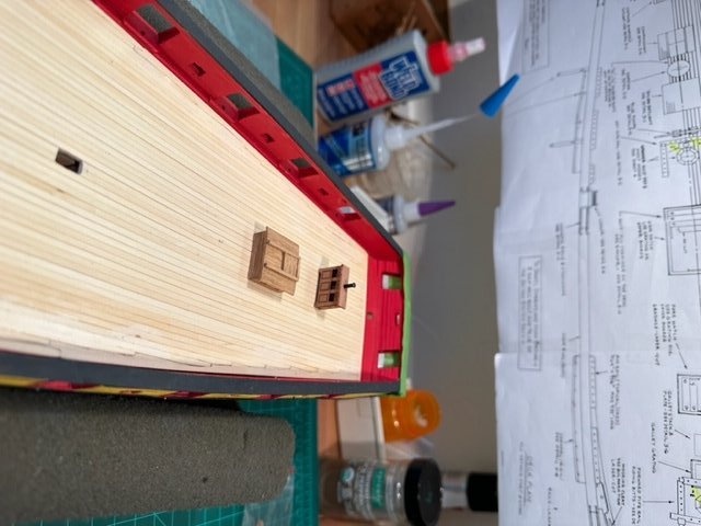
I never realized how much detail is present on the deck. Putting in only an hour a day or so tells me 1)it will be New Years of 2024 before this part is done; and 2) I need to find a way to spend more time on it. I have completed cannons, capstan, bell, stairs, cabins, tiller, and coamings. I still need to add grates or deck covers to the coamings, and to build the water pump. I am also working on one of the ship's boats as well. I have it shaped and I am proceeding with puttying to smooth out interior. Someone pointed out that most of the interior is covered by details, so I don't plan to spend much time on this. I am only building one cutter complete with all gear, as I plan to store it on deck over the main grate. And I still need to glue in the deck I fashioned, and install the rudder and the cap rails. This leads to the whole question of authenticity: The current ship is a replica of the original with accommodation to coast guard safety and navigation requirements. From what I have read, the ships on Lake Erie were quickly built, expected to have short lives, and were not fitted out for long cruises. I am trying to make something closer (hopefully) to the real 1812 product. So, it is highly unlikely the cutters were stowed on davits in the quarter area, but rather stored, stacked, over the main grate. If stored upright, they would have been covered with canvas presumably, to keep them dry. Likewise I am pretty sure there were no or maybe just one aft cabin. Keeping the deck clear was most efficient in battle. By the same token, why would there be hammock nets on the ship? From all I have read, the intent was for the fleet to sail out to battle, and then return to port each day, or stay out only 2-3 days. By the way, there is a great YouTube video about the overall history and battles on Lake Erie and environs in the 1812/13 period. The British ships at one point were docked in a harbor so close to that of the Niagara that an alert crewman could see the sails when they departed (and probably visa versa). The YouTube video is in a collection of naval videos done by a British historian (albeit mostly WW1 and WW2) and you can find it with a search for Drachinifel. The title is 'War of 1812 - Freshwater Edition'. Well, back to the minutia!
-
Just a quick post. I can only put about an hour a day into the ship, and even less while I wait for paint to dry. So, ship should be finished by about 2100AD I figure. More seriously, I am marching along with deck furniture. I found it useful to make separate copies of each of the mini-builds found on sheet 3. I have the large sheet posted in my work room, but I found it tiresome to constantly get up to measure or check something. I also copied the 4 'hull' prints (exterior, 2 interior, overhead) and have them available as needed. Many, many parts and pieces in this portion of the build. Working on the ship's bell today. Did the rudder and tiller yesterday, but I will hold off installation until all else is done on the hull (for fear of breaking the rudder off). By the way, I took a look at the metal galley stack today for the first time. Very strange shaped part. Does anyone know of an alternate source, or can someone provide recommendations for a scratch build??? PS: I also have shaped one of the ship's boats, and will be moving on to finishing with wood filler, some paint and adding it's furniture while I wait for paint or glue to dry on the hull. Ultimately, I plan to only build one of the two, and store it on deck over the main grate. I think the location found on the 'real' ship today is an accommodation to Coast Guard safety requirements.