DONATION DRIVE - SUPPORT MSW - DO YOUR PART TO KEEP THIS GREAT FORUM GOING!
×


milosmail
-
Posts
90 -
Joined
-
Last visited
Content Type
Profiles
Forums
Gallery
Events
Everything posted by milosmail
-
OK, carronades and guns all done. Pretty straight job, but very repetitive. I had previously built the three ships cabins, and I was viewing locations when it occurred that the capstan probably would not have been located there on the original ship. Or there would not have been three cabins (more likely). The capstan, in it's current location, would be unusable, what with the two cabins next to it. They are probably an accommodation to the modern use. So, I plan to only mount one cabin (maybe two) in locations where the capstan would have been functional, and possibly relocate the capstan farther aft. As no one really knows the deck layout, and I am trying to make changes more realistic to the likely configuration (hopefully), I am also planning to construct one ships boat (not 2), and show it stored between the masts. I think the number and location of the two ships boats is based on a coast guard requirement for a modern operating vessel. So, I am not building to the configuration of the modern vessel, but perhaps closer to that found in 1812. This ship is very close in design to the Syren (1803) in appearance, and I am using it for some guidance. Comments welcomed. Thanks all.
-
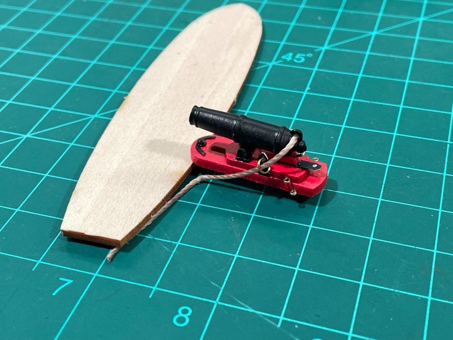
Well, on to carronades. This is a time consuming, repetitive task. I built one first to develop my approach. See attached photo (it still needs some paint touchup). There is nothing really tricky here, but you have to do everything 18 times! So, I work on them about an hour or so every day, most days, and I should be done in another week. Clean up cannon, rollers and mounts, prime and paint, cleanup and paint the carriages, make the Quoins and paint (I used straight stiff black wire for handles), etc. I assembled carriages, added rollers, mounted the eyebolts, fabricated straps from some styrene strips and attached. I did make a 'crafty' set of the curved metal bands found on the front of the carriage by scanning the shape found on the plans, and using Photoshop I created a sheet of duplicates of this image. I printed on a sheet of card stock, blackened the backside of each band with a fat felt tip pen, and then cut them out with an eXacto knife. Finally, I used a pin through the paper, and attached with superglue.
-
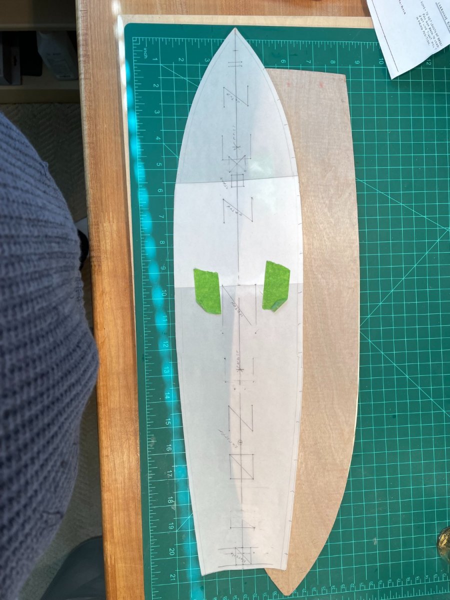
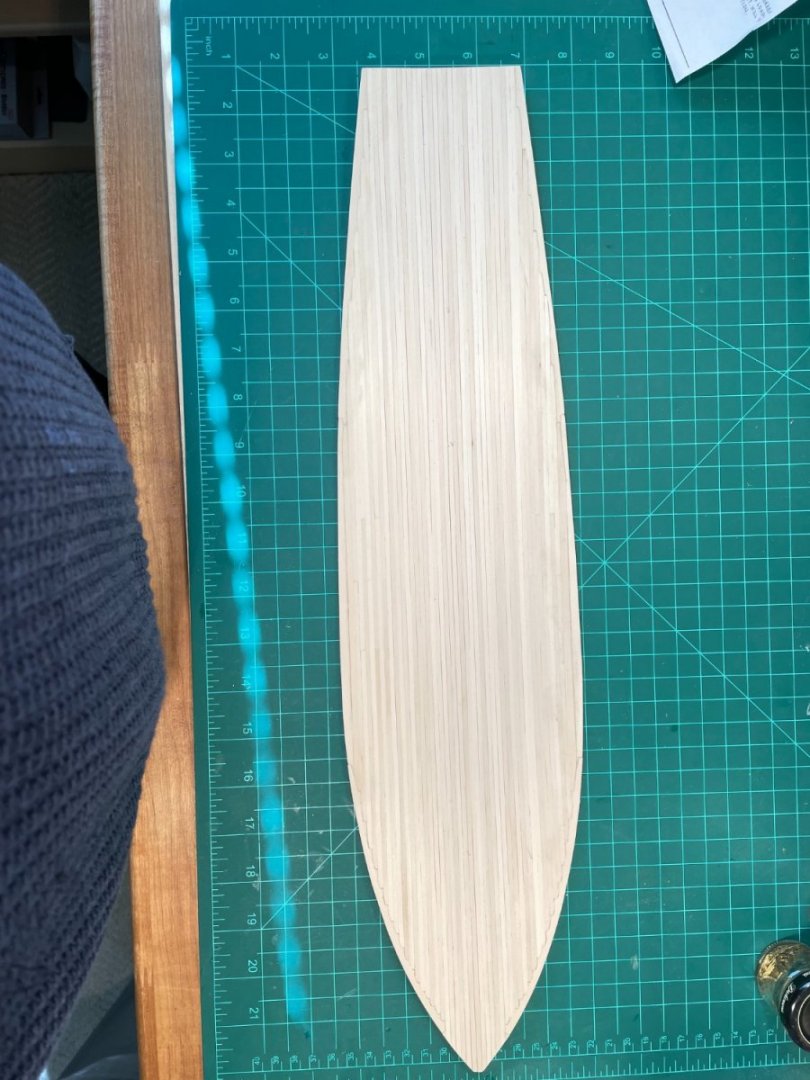
OK, second try...first draft vanished. I'm discussing how I planked my Niagara deck with nibbing strakes. I read several techniques found online and on UTube, and I settled on the discussion written up by an individual found under the url of "jimdab.com", dated Feb. 17, 2013. Then, I decided to try a technique which I believe made the process much simpler than direct planking onto the hull frames. I have not found any reference to someone else using this technique, but for me it worked well. I wanted the deck wood to be lighter than the kit supplied basswood, so I purchased a bundle of 1/16x3/16 holly strips as well as a 3in. wide sheet of 1/16 holly for fabricating the nibbing strakes. (These came from Hobbymill, which is no longer in business, too bad as he made excellent product.) I also purchased a 1/64 thick sheet of birch ply to use as a foundation. I started by making a template of the deck area from the blueprint on drafting paper (see photo). Along with getting an accurate shape, I was also able to mark the position of various deck furniture for later installation. I used this to draft an outline of the deck area inside the waterways onto the sheet of 1/64 birch plywood. I cut this out with my table jig saw, and checked the fit inside the waterways of the actual hull. I found the port side was a nearly perfect fit, but the starboard side was a bit wider at midships than the plywood cutout (hull was slightly wider). Next I needed to make the actual nibbing strakes. I used the outline of the waterways scrap wood (found on my billet WP4640-24), from which the waterways had been removed, and traced the holes onto the sheet of 1/16 holly I had purchased. I cut these out roughly on my table jig saw, and refined the shape (and width) using my belt sander to conform with the installed waterways, making them slightly narrower in the process. Now I had a set of strakes which I attached to the birch, and in the process I was able to adjust for the slightly larger starboard midships girth. This whole process took very little time. So, off I went starting at the centerline, using the approach described in jimdab.com, to notch the nibbing strake and shape the nose of each plank. I didn't do a prefect job, but got better as I went along. Note that the first 8 planks along the centerline do not notch into the nibbing strakes. I deviated from the plans in one respect. The plans discuss and prints show the deck planks tapering from midships toward the stern. I suspect, with no authority, that this was not the way the actual original Niagara deck was built. I decided to use the nibbing strake approach on the aft end of the planks as well, and this worked out well. Only the final plank outboard one each side required special fitting due to the curve of the hull. Once completed, I fitted the planked deck to the hull with no problems. I do plan to cut out the holes for the masts before I glue the deck down, but for now I am focused on making carronades....lots of little, little parts on each gun. More on that later. OH, and a PS: do not install the cap rails (see manual step 11) before you install the deck if you use this approach. Probably it will not fit with the main rails installed.

-
Thanks for the comments. I am posting photos and some technique today.
-
I am restarting my build log. I had to suspend construction in 2019 for various reasons, 2 knee surgeries, covid, etc., etc. I don't know how to or if my old build is still available, but let's start from here. Hull is completed and painted. I built the deck with nibbing strakes. Starting on cannons. Pictures will follow (Iphone not cooperating today). PS: I build at a slow pace so posts will not be regular. I got a plaque from NRG stating "Tain't a hobby if you got to hurry" and that is my motto.
-
Excellent beginning. Looking forward to your progress. I need to restart my build log, as I stopped work about 3 years ago for various reasons. I have just completed planking the deck, and will resume from there. Looking forward to your progress.
-
Really nice build on your Niagra. I have been a lurker reading your blog, and I appreciate the info. on problems you encountered. As for mounting , We probably all made the mistake on our first kit to not drill mounting holes in the keel at an early stage. I know I did. Looks like you recovered nicely. Mine is going slowly, as life has interfered over time - mostly a couple of home remodels... I have just finished painting the hull and moving on to planking the deck. Well, enjoy your ship. What's your next build?
- 843 replies
-
- 2
-

-
- niagara
- model shipways
- (and 2 more)
-
This may have been previously stated, but... When you set the mast(s), be very sure you start attaching lines from the inside (i.e. closest to the center line) out. But, attach ratline shrouds first, to stabilize the masts, then all the standing rigging. Then any running rigging you want to add. You may want to put some running rigging on, such as sheets, braces, halyards that would normally be present on an operating ship at dock. Even without sails present.
- 843 replies
-
- 2
-
-
- niagara
- model shipways
- (and 2 more)
-
I never glue in the masts. They will be very snug once all the shrouds and stays are attached. They won't wobble, but be sure tension on shrouds is equal, such that mast is upright with the proper rake and vertical side to side... But, still very difficult to remove once many lines are attached to the deck and railings.... So just paraphrase the old carpenter's saying - measure twice (at least) and cut once.
- 843 replies
-
- 1
-
-
- niagara
- model shipways
- (and 2 more)
-
OK, vacations are done, visitors are gone, so I finally have time to get back to it. I have been building the scaffolding round the gun and sweep ports. In the process I discovered a manufacturing error. My bulwarks for section K were not equally spaced from the center keel line (not symmetrical), and in fact the port side was 3mm narrower measured from the center keel to the inside of the bulwark. This became very apparent when I placed the cross brace from K to L at the tip of the bulwark. I went back through alignment measurements - everything was square in all 6 axis, so I measured the space left on the billet the parts came out of. Sure enough, one edge of the bulwark was closer to the center line than the other. In fact, I found none of the bulwarks on that sheet were symmetrical. Must have been a bad day for the laser cutter.... I was able to fix the problem with a shim on the exterior side and some shaving on the interior surface. I am now complete on this step, and I did not find any other significant problems. But, it's just one more thing to watch our for in construction.
-
Very ship shape (excuse the pun). It's looking really well done.
-
Regarding anchor rope; remembering this large diameter rope could well run over 300 feet or more, and when it was not stowed below deck, then it would have been coiled in a figure eight pattern called a flake, and left on the deck near the bow. Flaking minimized the chance of the line fouling when the anchor was dropped.The working end would have to be available at the capstan, as that was used to pull it up. I believe typically when the ship was at sea, the anchor rope was detached and stowed below. It would be brought out only when anchoring seemed to be a probable event. I would run your rope through the forward grate - even drill or cut out a neat gap for it to fit through. Or flake some on the deck for a satisfactory appearance. I was told once that the anchor rope for the Victory was run from the hawse below deck to the capstan and back several times, and not flaked due to its large size. Seems to me this would interfere with gun recoil, but maybe there was enough beam.
- 468 replies
-
- 1
-
-
- niagara
- model shipways
- (and 1 more)
-
Dale, isn't it nice how we get to be carpenters, painters, plumbers, electricians, riggers, sail makers, steam fitters, etc. I like the photo of the chain plate. These are really simplified from others I have seen, made from links or made from a solid bar. Easier to replicate. Yours will be fine. By the way, not sure on square riggers, but on a modern sail craft, the lee side stainless steel stays will always be slack as the mast will bend a bit. I suspect this was true for wooden masts with hemp/manila shrouds as well.
-
Larry, what kind of wood did you fashion your oars from? I take it you cut the blanks from wood the thickness of a shaft, then did a lot of filing/sanding? Did you grind the shafts down first with a Dremel or? They look great, and I want to repeat the process.
-
Dale, the ships boats are really looking great.
-
Very nice deck, Larry. Wood finish looks natural as is. I usually mount or mark deck coamings positions, cut planks to fit around. But I may try installing on top this time. I still hope to use nibbling strake, but if it gets too difficult, I will abandon. I probably will run planks full length, as you did.
-
Boats are looking great. Glad to have you blaze the trail (calm the seas?) for me. Mine is going slow; still working on gunport framing prior to planking.
-
Well....., I was going to post pictures today (but that was before I discovered I had washed my IPhone with my other laundry - oh well, I wanted a new IPhone 6 anyways). Once I have the new phone, I will post some shots again. I am in the process of executing the gun port/oar framing which is not difficult. Tedious due to the planksheer needing fill to match the thickness of the bulwarks as previously mentioned. I plan to plank the external hull from the caprail down to the waterway, and then begin with the garboard strake at the keel. This is my least favorite part of construction. I enjoy making deck furniture and masting/ rigging, but not planking. I am also going to try to make nibbling strakes for the edge of the deck planking. Has anyone else tried this? If so, I would love to hear your comments. Or anyone else wishing to tell me I am nuts and talk me out of it....
-
Had little time to work the past few weeks (my daughter has 7 month old twins which are a handful), but getting back to it now. Has anyone deviated from the painting plans on the kit? The green interior bulkheads seem out of place (shouldn't they be red?), and the red coamings seem wrong also, at least with respect to authenticity. I think the kit is just following the color profile of the ship in Erie. In looking at painting of models vs the posted picture of the real Erie ship, I was struck that on a large scale, the red and green are much more muted. The model paints are too bright. And, I have never seen an historic painting of a war ship where coamings were painted red. Also, I noticed the cabin sides are painted on the Erie ship (for maintenance convenience?) whereas on the historic ship I would have assumed these would have been varnished. Anyone have any thoughts on this?
-
How is the planking going? Here are a couple of thought. Planks do need to be tapered within the belts (duh) as they approach the bow, but no plank should be tapered less than half its width. Are you aware of the joggle strip technique? I don't have any photos, but essentially you make a custom fitted piece to dove tail into two narrow pieces near the bow. Sort of the opposite of stealers, which you will need at the stern. If you have access to recent issues of Ships in Scale, there are a series of articles on planking by Bob Hunt which demonstrate the use of stealers and joggle strips. Planks will not necessarily lie flat (although this is the ideal), but you must exercise care that planks doe not curve downward at either end. There is a tendency for planks to do that on some models, if not corrected. Have you been beveling your pieces? This helps with the fit as well, especially where hull curvature is pronounced. Otherwise you will have gaps between planks. These can be filled with wood putty, but I find that the puttied areas do not look the same as the natural wood after painting. I prefer beveling. The planking layout shown on sheet two do not show any joggle strips, but no two models are exactly the same. In fact, the two sides of the ship will not be the same, so don't try to force it. And remember, painting will hide a lot of the planking detail (and errors). If you can't find the SIS articles, post a reply and I will try to find a photo.
-
My computer crashed last Friday (bad memory chip corrupted the Windows kernel), so I have been busy rebuilding it. Back on the air now. Yes, a quick check showed most of the sills were too narrow. I had already painted them in preparation for installing, so I think I will add strips of filler after they are glued in and then shape when I add exterior planking. Is that about the right sequence? Meanwhile, back to the knightshead....
-
I looked at sheet 5, and I concluded the following: as the outhaul was not connected to any sail on this rig, it must have served as a brake to keep the jib boom from moving aft under load. I would believe these two lines would be secured to a bulkhead after running through the chock rail. They might also have been attached to the bowsprit in some fashion inboard of the chock rail. They would likely have been a piece of seldom adjusted rigging - but I am guessing here.
-
Outhaul and downhaul serve different purposes on a triangular sail, but both affect the amount of 'belly' in the sail. It depends on wind conditions and angle to the wind as to how they are adjusted (I have raced boats for years, and generally we do not adjust these lines much). So, they are different lines. Keep in mind that where lines were secured varied a great deal; frequently changed depending on the master or the captain's preference. So, pick a spot that seems natural to you (no crossing lines - that's a big no-no as it causes a lot of wear in real life), and secure. You might go as far as adding a cleat if needed.... No one knows where these lines ran on the original ship, but I suspect the run of lines on the model correspond to those on the replica on Lake Erie today.
-
So, the gun port sills are not wide enough? I will give them close inspection. Dale, thanks for another good tip.
-
I coat my lines with bees wax (cuts down on the amount of dust collected) and then run it over a light bulb. The heat of the bulb relaxes the line. By the way, nice catch on the 3/8" scale. Glad you mentioned it before I got to that point. I checked plans and found several other instances, including the knighthead (2B- and bulwark x-section (2A-A).