HOLIDAY DONATION DRIVE - SUPPORT MSW - DO YOUR PART TO KEEP THIS GREAT FORUM GOING! (Only 13 donations so far - C'mon guys!)
×


Small Stuff
-
Posts
162 -
Joined
-
Last visited
Content Type
Profiles
Forums
Gallery
Events
Everything posted by Small Stuff
-
 Hello friends, due to the fact, that the drawing is made in 1815 by Master Dughty, the kit is surrealistic, because it is dated to 1812. But the kit is there and I shoot some pictures for you with a CA$coin and an €coin of one cent on it: This is a small secretary in the floor I made the photos on, This because I decided to place the built model over it in a strait showcase. now know why the kit was as cheap as I bought it - the one bulkhead is cracked and some of the others were poorly sawn. But this is nothing that couldn't be fixed. And now...
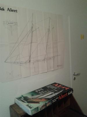

-
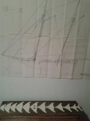
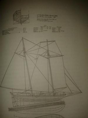
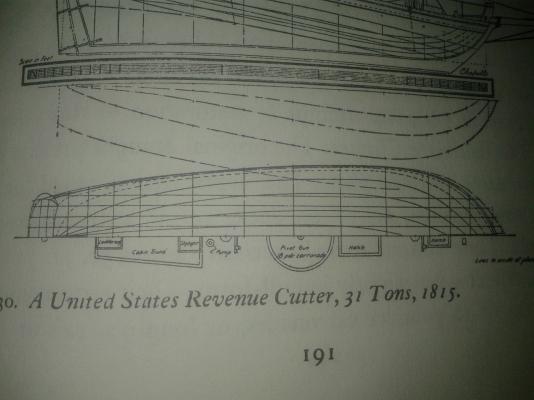
Hello viewers in your chairs, Frank told me the deck of his kit (mine is still under way) is stem to stem 21' long. So lets be mathematics: This means 21' is 533,4 m/m in 1/25 this gives us 13.335 m/m in 1'=12'' and so we get 43 3/4 ft Lod for the originl Revenue Cutter what might be a "fact" that I sholud deal with the 31 3/95tons Cutter plans which were noted by Chapelle with a >>Length range on deck: 48'6''<< So these were the Plans my friends:
-
Here the very diffrence between the two R.C.-types 31 3/95 | 51 3/95tons Length per perpendicles: 46'6'' | 54'6'' Length range on deck | upon deck: 48'6'' | 56'8'' Beam moulded: 14'6'' | 17'0'' So we'll have to devide these through 25 to get the modells measurements.
-
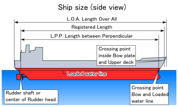
Hy Augie, sorry for writing in here but it might be a very old but important question - helpful to a plenty of members confused by diffent length(e?)s used to definite a ships proportions. These diffrent length(e?)s are not too confusing if you look onto this drawing - source wikipedia: Hth, Chris
-
Hello Frank, due to the fact that I ordered her,too, I'm following your build with high intrest. You plan to build her double layered planked? Thanks a lot for showing your kit's progress, Yours Stan
-
Hy Wayne, thanks for the interestng informations. Now the kit's length is 864 mm what gives to us 21.600 m/m in 1ft=12inch or 70,86ft so it might be the 79 62/95 tons with its 69 1/2 ft length on deck... But this is a wrong trap! Because the Length on the box will be a length over all to get the illusion of getting a BIG shipmodel out of the kit! So we'll have to ask Riverboat to measure the decks length on his kit to figure out if it is a 513/95tons or a 313/95tons Cutter. This from here and me today,
-
Hello friends. As I restarted my life in a new flat as a single in may of this year I restarted my hobby also - but my right eye got so bad during the last few month that I was forced to stop car driving. So I crashed the Ranger and got mad of being unable to built anything intelligent until today. I got a book at ebay and found the old Krick kit of the Alert! And I got mindsick and bought it spontaniously - due to the fact that 1/25 might be an intelligent way to outwit my eye. W'ht'n'heaven hav' I done? I first decided to bash the kit, and had to figure out that it was easier to rebuilt it scratch. Then I got the information to have copied the wrong plan. So I decided to make use of the 1829 30tons one due the rectangular hull lines. Because of this I changed the titel and set in this small statement for you to show the development of the buildingstory. So I'm awaiting the pacel and started looking for some literature and background information: https://www.uscg.mil/history/webcutters/Alert1818.pdf But in there is an intersing group of words: She was constructed of live oak, red cedar, and locust, with four ports per side. Does this text mean square formed ports with lids? ...and is the Alert of 1818 of the 57ft-Class with 75tons (without fractional number XY/95 ? I couldn't belief! ) the wrong prototype? And do I have to buy the AotS Book of Alert 1777? Perhaps you can help - during I'm rummage around in my issiue of Chapelle's book The History of the American Sailing Navy to find further answers... and start reading here: http://modelshipworld.com/index.php/topic/6400-alert-by-riverboat-krick-125th-scale/ Yours, Small Stuff
-
Dear friends, I'll have to struggle my way through the problems restarting with the "Ranger" kit towards this model... So I'll prepare myself here with some propgress during the next weeks - but before the Coreel Kit from "Ranger" must be done. Let's stay with the first idea... it was the best one! Yours Stan
-
DigiCam2USB-wire was found some seconds ago!!! So after the weekend&party here, And there 'll be some new pictures.. The cat played with it untill it was gone unter the cupboard and left there for the vacuumcleaner's snorkel

-
Still getting used to the TurboCAD20 2D Editin... so:

-
As I'm fed up with the unability of my TurboCAD14 to open Daniel's drawings I decided to buy the newest XX. edition!!! So I did...
-
Daniel sent me the sectionplan drawn by his AutoCAD-knowledge ! I maanaged to print it - tomorrow I'm going to enlarge the drawing in the copyshop. He also send me some literature about historical shipdesign in CAD So I will try to work out the basebord at the central part of the sideview - so I'm going to start this evening with TurboCAD Designer 14 a 2D-program...starting with some Youtube Tutorials. Till Than, Stan
-
Great work you do!!! Your Triton is great - thanks for sharing! Stan
-
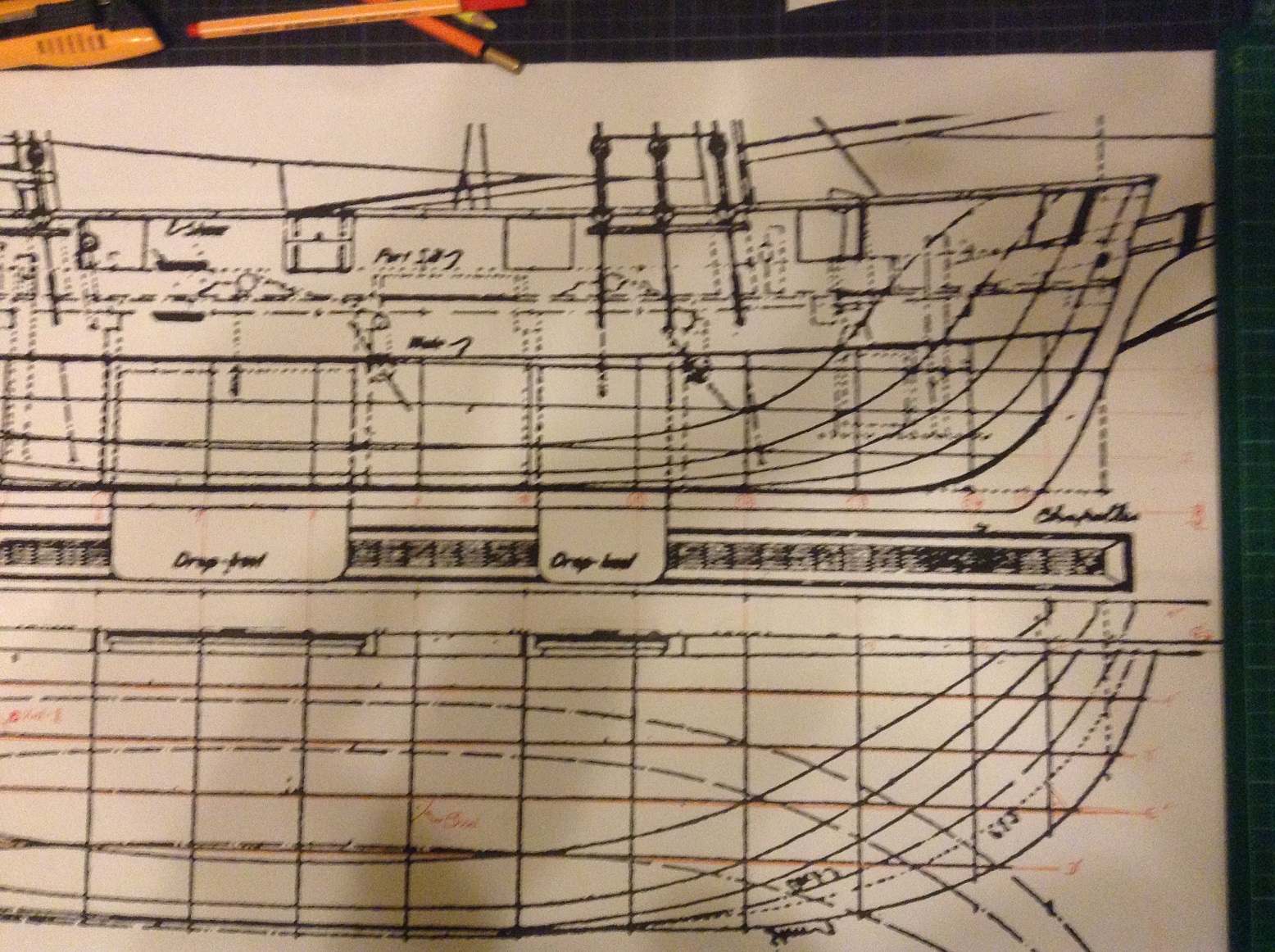
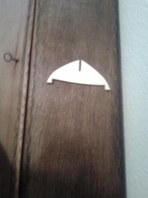
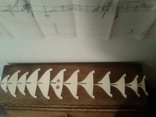
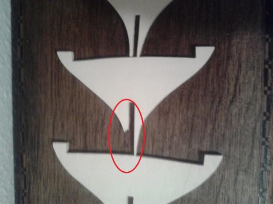
The section plan shows the moulds - because when I put the section ogf the hoistin apparatus under the transparant paper the sidelines crossed the inner side of the planking amd the edging of the formers!!! :dancetl6: :dancetl6:

-
Tomorrow I hope to find some time to begion to put some basic lines of the section plan into my TurboCAD and trying to print it on transparent paper to get a scaledplan out of the work I do... Daniels support will bring a plenty much more details to the body plan. I take my measurements allways from the very middel of the lines - because there must be the original line of points from where they were enlarged. Yours Stan
-
Wayne - thanks for your answer. What I'm really affraid of is the fact that the hole drawing is a distorted one - (perhaps only in this single book?). So the hole project would be raised in question. Because my basic data is corrupted. Or may it be an effect of the enlargement in the copyshop based on the working of the paper in the heat of the copying process? I don't want to give up the (model) ship!!! Hopefully you can understand my anxieties, Stan
-
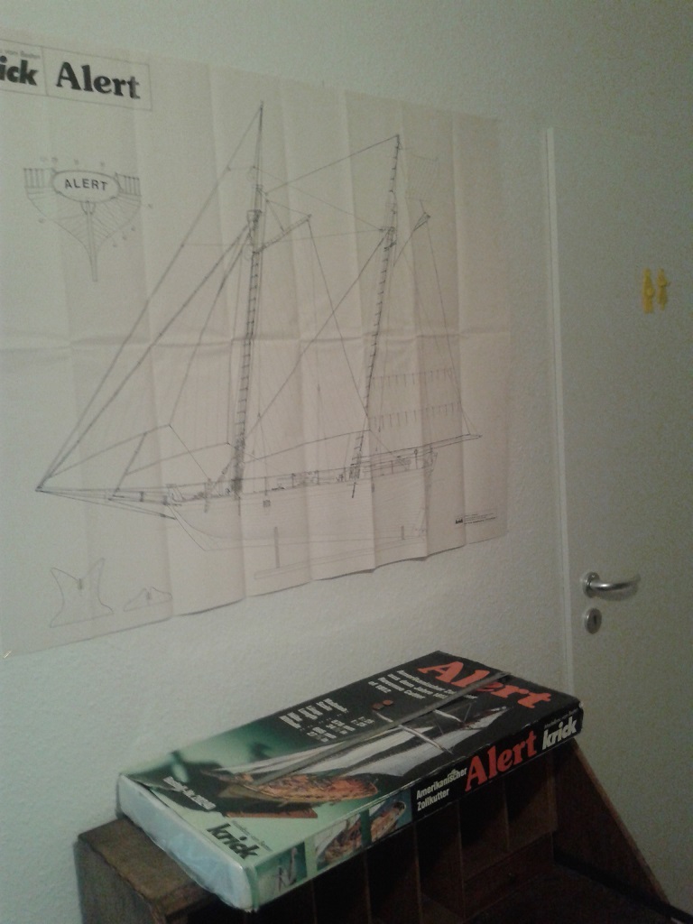
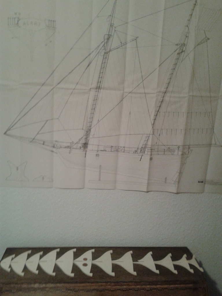
Dear friends, I read a plenty during the last nights and found again the interesting lines written by Mondfeld in the book "Historic Shipmodeling", In where he pointed out that's most important to know where the model will be placed later - and to search for any historical information you could find. So I'd like to ask two and a half questions to all of you: So I asked myself where to showcase - and NOT store away - the model of a single yard later. And so found a place over my four drawer tallboy (an old Louis-Philipe type I restored several years ago to an ash antiquity back from a nurserals red painted furniture for toys.)Then I thought about dust... and about a display cabinet to protect it. After this I came to the question where to put the information belonging to the model for the visitors. (Several models can't be identified nowerdays due to the circumstance of a leck of information - also in the NMM-collection i.e. the well known "The Shearnes" SLR o368 http://prints.rmg.co.uk/art/515691/Model_of_a_warship_frigate_36-40_guns ). Perhaps my family doesn't bin it at all after my death - so it may pass through sundry hands... I figured out that Chapelle himeself wasn't shure about the distribution of the names of the four ships. As his knowledge is at latest from the 60th there may be some increase of knowledge now. But as I'm a prudent and conservative person I would only like to ink onto the model what is ironclad, So our R.M.-Wayne and others may please be so kind to tell me if I have forgotten to add any important/up-to-date information to any beholder - expecially those with naval background. United States drop-keel Revenue Cutter of 66 55/95 tons built in 1825 for shallow water action - assumed to be "U.S.R.C. Louisiana (II)" Construction by William Doughty, US Revenue Marine Plans and information by Howard Irving Chapelle* Reconstruction and built by CP in 2014 -20?? Scale: 1/2 inch to the foot = 1/24 Buildingtyp: double planked on bulkheads Modeltyp: fully equipped hullmodel Modelsizes: Length: hull length** : 863,5 m/m per perpendicles: 762,0 m/m Breadth : on moulds: 279,4 m/m on planking: 286,5 m/m Draugth: CWL to false keel: 71,0 m/m CWL to drop board: 125,5 m/m 2 x pivoted 8 pounder long barrel smoothbore muzzelloader on sliding carriage 4 x 18 ponder carronade smoothbore muzzelloader on sliding carriage *„The History of the American Sailing Ships“ & „The History of the American Sailing Navy“ **meted from galion knee to transom bulwalk {LengthDeck: 798,5 m/m -LengthCWL: 261 m/m } (It will be formated nicer as I can do it in here. ) Or should I take the original measurements of the ship instead? And when I measured the place to be fo it so I find out, that there is a plenty of place on the stand. Because of this I collected the data for the information panel. I think of printing them on laid paper of 190 x 190 m/m in a nice frame under museums-glass.Due to the large scaled will the model will demand a big showing caseof whopping dimensions: L/H/D: 1000/350/350 m/m- I have been told at the glazier to invest money in a long time thought solution made from UV-absorbing glass and if it will be put in sunlight in summer to finish the hole model supplementary with a row of layers of UV-absorbing clear lacquer in an areosol can - "Yes it's a gargantuan invest - but it will save your work for a very long time.Do you thing that this will be an oversized solution - as we tell it in the IT-department? Thanks for your intrest, answers and help - yours, Stan
-
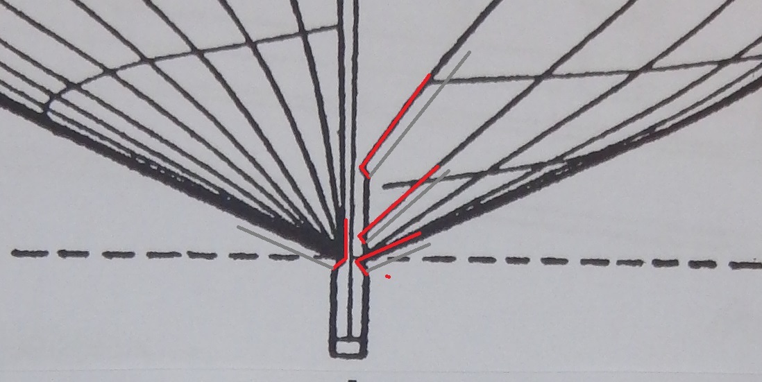
Here the namining of the lines in red:

-
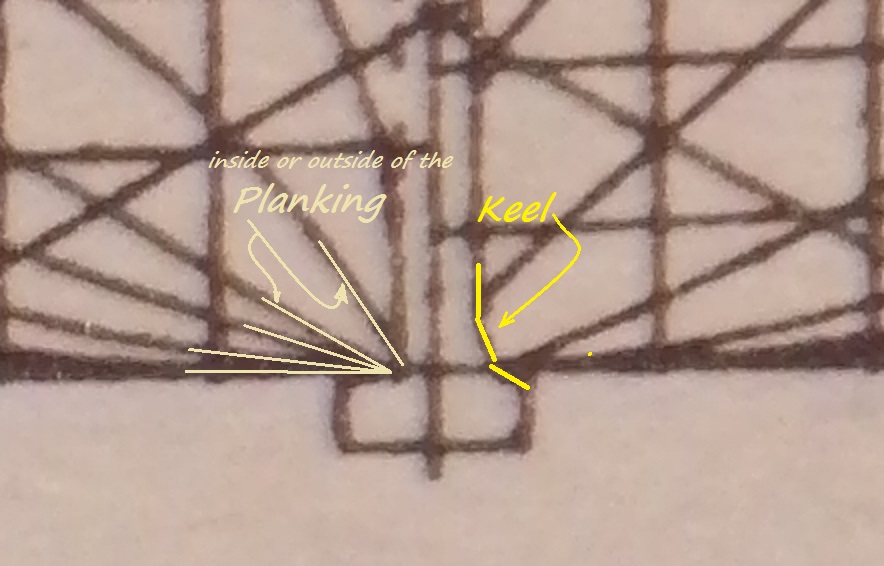
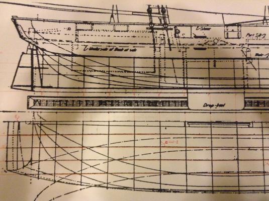
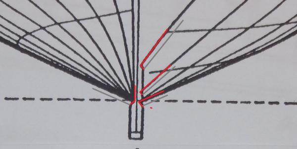
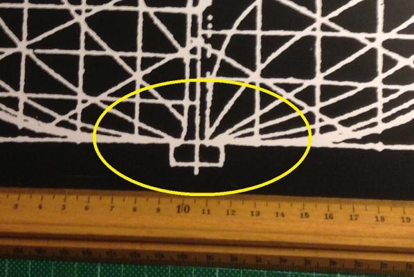
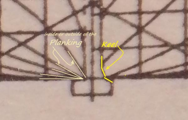
Suddenly there is a horrible question ...is this plan drawn on the moulds or on the plankings outside??? When I enlarged th plan I took the beam on moulds to the half and looked if the breadth is like this in the waterlines drawing... at the formers crossing the bigger dropboard by enlarging out of the book up to something like 1/100 or so. And when I enlarged to the 1/24 scale I switched (due to the eaasier taking of maesurent on a shorter line) to the breadth in the sectionsplan using the same measurement... was this the wrong way to proceed?????? Even if both is onthe same "slip" of paper???? EDIT: In this photo of the Chapelle plan of the 1806 HMS "Flying Fish" we can easily see the rabbet for the beveled planling - so it is a drawing of the moulds(red) not of the planking's outside (grey). but what about the inverted drawings details in the yellow circel??? Con someone of the sophisticated readers in here tell me what kind of plan this might be? Staying irritated Stan - who may be this night able to gauge the hole plan.
-
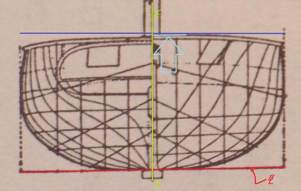
I've been able to fix the first line-names tonight - picture will follow. I Think there is a failure in the printing of the plan - only visiable by these tremendous enlargements: The redline is the BaseLine (BL) and green one the CenterLIne (CL) [the blue one shows where the plywood should end - parallel to BL octogonal to the CL] the light-blue part of the bulwalk shouldn't "run down". Shoultn't it be maximaly rectangular to the CenterLine ??? Edit: I pictured the plan in this way to show the problem very blatant to all of you. Greetings Stan.
-
She looks at my work, too:

-
That's very kind of you, Bugra!!! This evening would be fine. Your's Stan
-
This is an interestin' tricky thing you do, Tomin!!! I'm usually the one being very well in making thinks much more complicate than anybody else could ever think about it - as in this case again. I think I'll try a redrawing of the sectionsplan first on transparent paper to get something I can take the measurements from and "decant" it in the turboCAD... Yours, Stan
-
Thanks Bugra for watching! I think abaout TurboCAD but don't have any experience in CAD... but as far as I understud I can enlarge it and reduce it as I want... That's abig sore temptation. On the other hand I it will need time to do so - but it's much easier to undo problems as to try to redraw something running wong. Yours, Stan
-
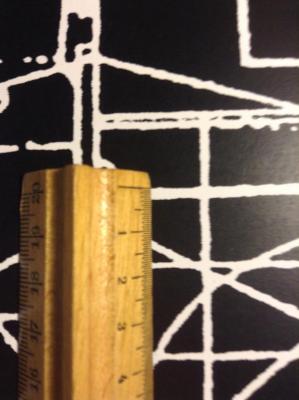
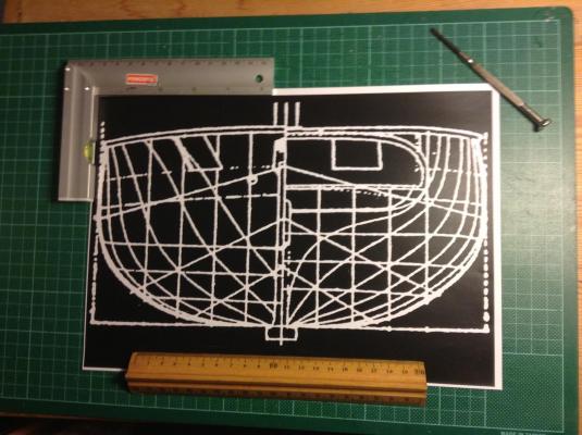
Hy colleges of the sawdust, here the inverted drawing with a imperial and metric ruler and the detail of the lines appearence shown with a 1/2 m/m ruler for you. And b.t.w. this i-pot cam doesn't work as well as my digicam had had done... But as we're used to say in Germany: "But better than nothing!" Yours, Stan