Small Stuff
-
Posts
162 -
Joined
-
Last visited
Content Type
Profiles
Forums
Gallery
Events
Everything posted by Small Stuff
-
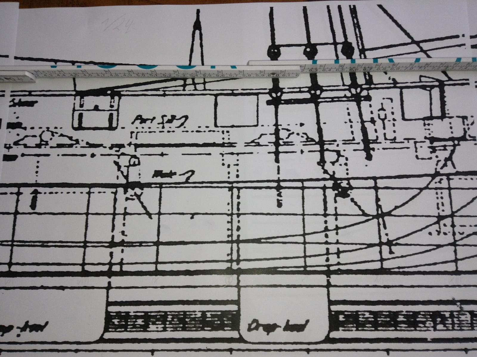
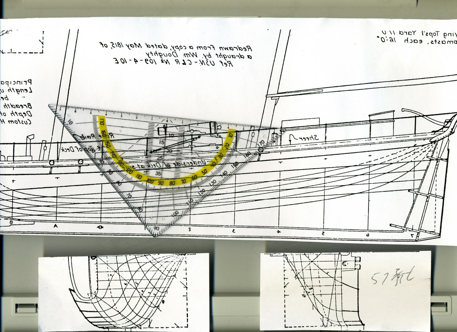
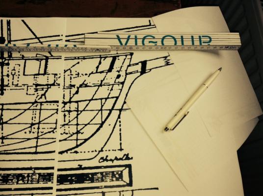
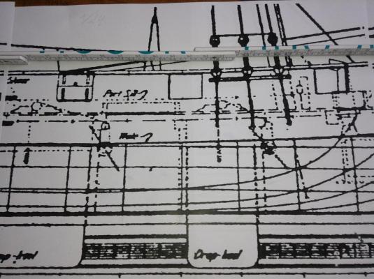
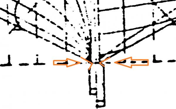
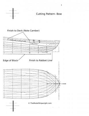
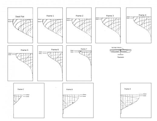
 By the enlargement of the plans out of the book by 300 % to get a copiable master drawing and again enlarge it by 350% up to the scale of 1/24 But in the copyshop some of the lines grow up to a horrorfying fat broad brush bar... of inch/10 So thought about this: I inverted the sections plan into white lines on black ground and I'll have to try to redraw it on the middel of the lines. Can this be a proper solution? Stan
 -
Hy friends, looking to the sections I see the beastwork is curved to outboards. When I keep them at he bulkheads as "horns" the can break out easyly? Best to see at the first frame in the drawing above - because of the gunport's position. Should I draw the sections with them or without? If with them how thick do the have to be - what is the typical thickness of a breastwork? How to bring the curved surface in a right way - but in what way with or without "horns" at the bulkheads? The copies are to made in 1/24 tomorrow - the I'll be able to make pictures for you. Yours, Stan
-
Thanks Bob by your comment I found the irritation to all the other that don't write... thanks for this I altered the titel. Hth, Stan
-
Hy Bugra, and yes -indeed Bob... one will be a 1/32 fully rigged one for the export to Leipzig and the larger one a 1/24 hullmodell is done here. The 1/24will have a beam moulded by 279,4 m/m the 1/32 scaled of only 209,55 m/m. There will be a lot of work but alltogether the are "group of two" so I can intertransfer the results I gathered during the time of building. Now I have to structure a scedule hat shipmodel is to built first, second, third, e.& - and finding reasons why I do it in this way. The details of the hoisting apparatus must be shown dramatically clear and fine in 1/2"=1'-0".. Yours, Stan
-
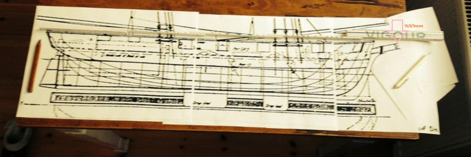
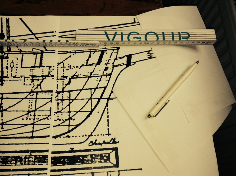
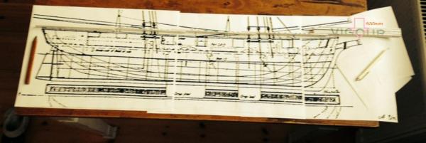
Hello friends of the hullmodel scratchbuilding... Due to the fact I could build a hullmodel of the schooner here my collection of pictures - that will be elaborate during the next days. And the better detail of the bow part with a pencil to compare. The beauty will be 900 m/m or nearly 35 1/2 inches long. and Yours, Stan Edit: Adding the last two pictures showing the tremendous size of this hullmmodel and the cutting of the bowsprit.
-
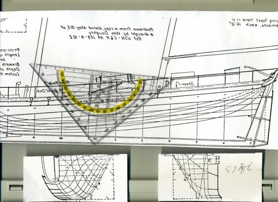
Thanks Eamonn, fpr the motivation - but what I need is the possibility to put these two plans to consolidate: Because I need one area that is found in both drawing... the easiest to find was the CWL - blue in the drawuings. But in the sections plan it is a curved line! Nothing I've ever dealt with... Okay, this'll be my problem for this weekend. Yours, Stan
-
I don't have a 1/48 planking or dechsplankingh plan - All I've got is the Chapell's drawing I atteched in here above. I don't trust the Corel's drawings - so I don't think I should enlarge them from 1/64 up to 1/48. So as you told me the drawings of the Ancre Schooner will be very helpfull to me. Here my backbone II with my first trial to place it on a stand. Hoping you like it, greeting over the seas, Stan
-
Mark untill I've got a lathe I can only built hullmodels - they also save space in the flat and the area at the showcases to clean is a significant smaller one.
-
Look Gluck with your personal rebuilt, Mark. Oh yes it's a bold descission. But I think it's the best you could do for yourself. And I copied your "Lessens learned" into my Literature - folder together with the sentence: "Buying tools cheaply'll bring you to buying it twice." Yours Stan
-
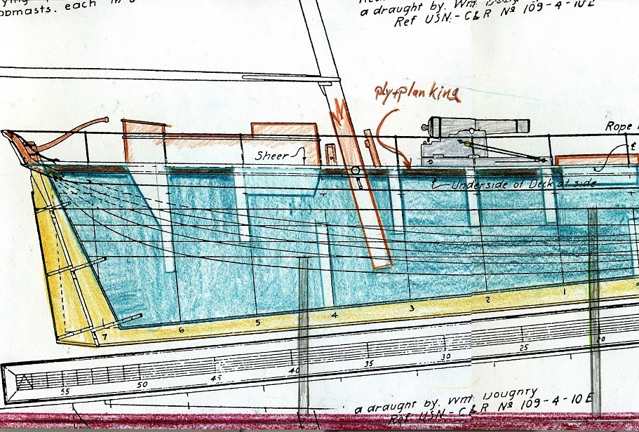
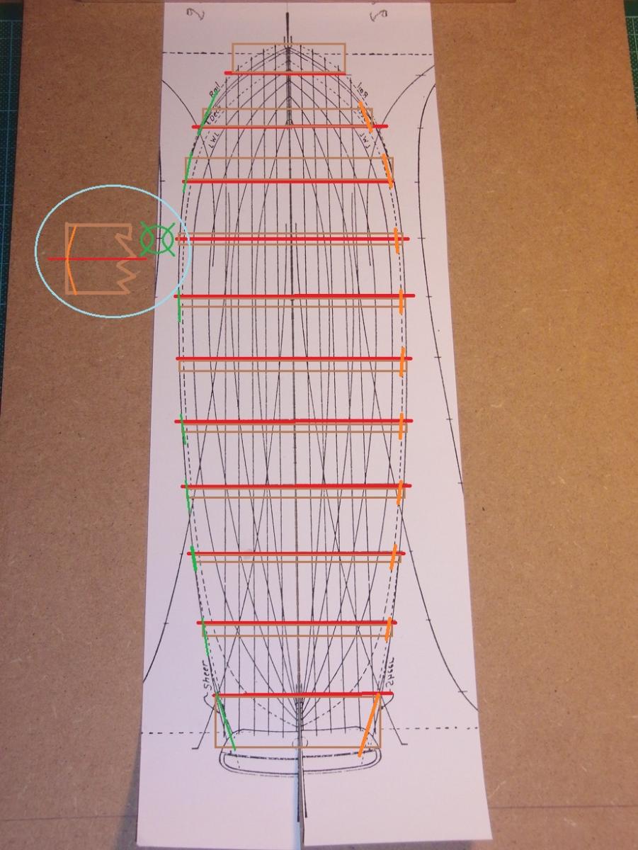
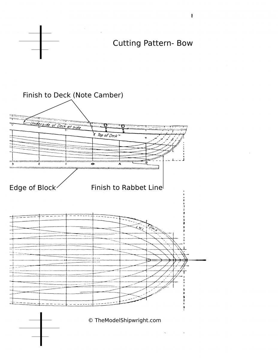
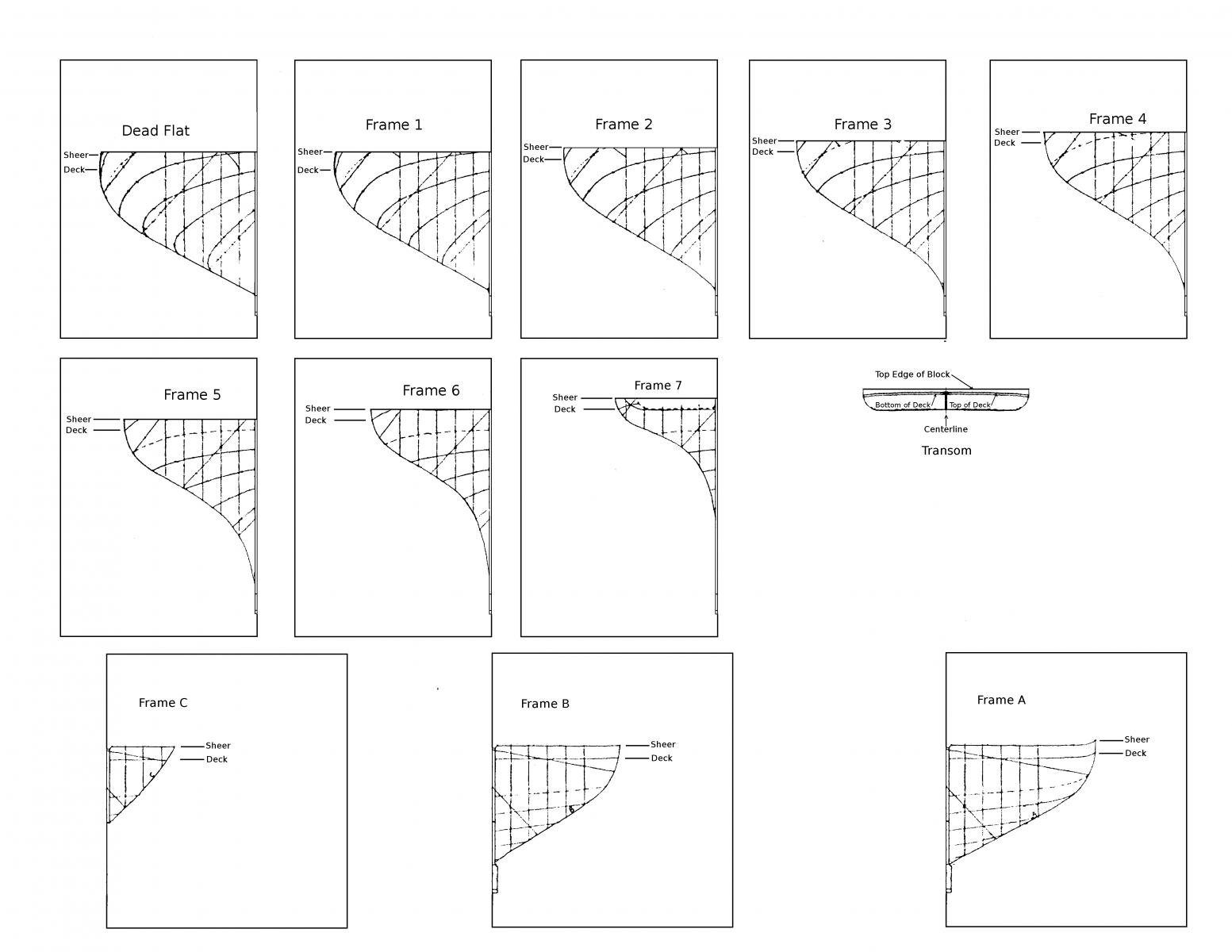
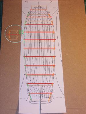
Thanks Eamonn, I found this in the planing stage - but if I find those many fails in the planning stage what mass is still hidden for the building part of the model??? Okay... I'll figure out those problems later... The OUT - and INplanking drawing was a problem I never have dealing with because Tamiya hasn't got handed out such problems out to the modelbuilder. So I was shocked and found the sections are all drawn INside of the planking - so I can saw them out (when... IF my wood comes to me) by glueing a mirrowed and an original half of the sections plan together on the plywood. and I get from this drawing the dimensions of the keel wood, too. So far the INside part. The OUTlining is only in the waterline/horizontal plan - what I only use for the arrangement of the bulkheads on the yardground/buildingboard.The brown boxes shall show the position of the bulkheads with glueingfoot on board - and the green the outlinerunning of the plankings outline. The orange shows the beveling of the bulkheads. The planking will be a 11/2 planking - by filling the space between the bulkheads with softwood to get a glueing surface for the planking. What is the thickness of the planking on these American Revenue Marine Cutters? Mondfeld talks only about continental and R.N. planking and Chapelle about coast crafts but U.S. R.M. shipbuilding might be diffrend.This will be important because I have bought 0,6m/m pear wood vaneer - what means 28,8 m/m in the original or 1.1338582677165354inch what seems to be a little bit skinny over the rips of the bulkheads... so I might have to add an cheapwooden "underplanking" to come to the original thickness. Do you think I'm stilll "on a good trap" to come to a welldone solution with my planking? . Yours Stan
-
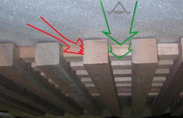
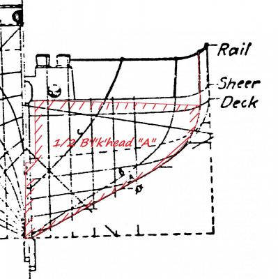
Okay Eamonn, thank you for these bouquet of very good solutions... I updated my between-ears-software by reading{1. As I read the "holes" in the grating were max. 50x50 m/m {2 due to the heel's measurement of the shoes theier days - not slapsticly getting stuck in the hole with the heel By this "rule" the holes will be 1,0467 x1,0467 m/m But the "problem is the viewers can see deeper inside wehen the look between the tick woods - don't konw how the tell you - the graphic in the picture may hopefully give you an idea you need... :blush: So I think I'l have to get a little bit deeper in the hull depending on the angel of the view of the visitor. It is very logical to read in the books and suddenly getting so complex to "translate" it into just and only the "planing" of a part of a model {3 So I thing cutting away something from the false keel/backb'n' has always to be "answered" by strengthem it by adding wood (or a sheet of metal) And all this without any 1/2048 cubicinch of wood in my hand... _______________ {1Oh yes it's an oldfashinon way doing so. ...as my child was made in Germany & born - not ordered, paypaled & downloaded {2Mondfeld "Historical Shipmodels. A manual for modelbuilders"/Mosaik edition 1978 (p. 122 "Grätings" ) {3 lots of thinks receive attention coming "from diffent corners" of the model and the original... I've to admid I'm feeling a little bit like a person between two dimensions - the one dealing with the originalship in a 3D-copymachine to reduce it down to 1/48 of it's original size by transforming the originally used material into something still working honing it down to the scale size. In the other dimension i've got my plan 2D triying to enlarge it into something in the room. With the goal of "filling" the reduced original from above. {4 {4 A typical misidea was to pull b'lkh'd "A" away from the mastfoot just cutting a new slort into the backbone... and realising that I'll change the waterlines doing this- than I tried to alter the sections outlines... And here the result:
-
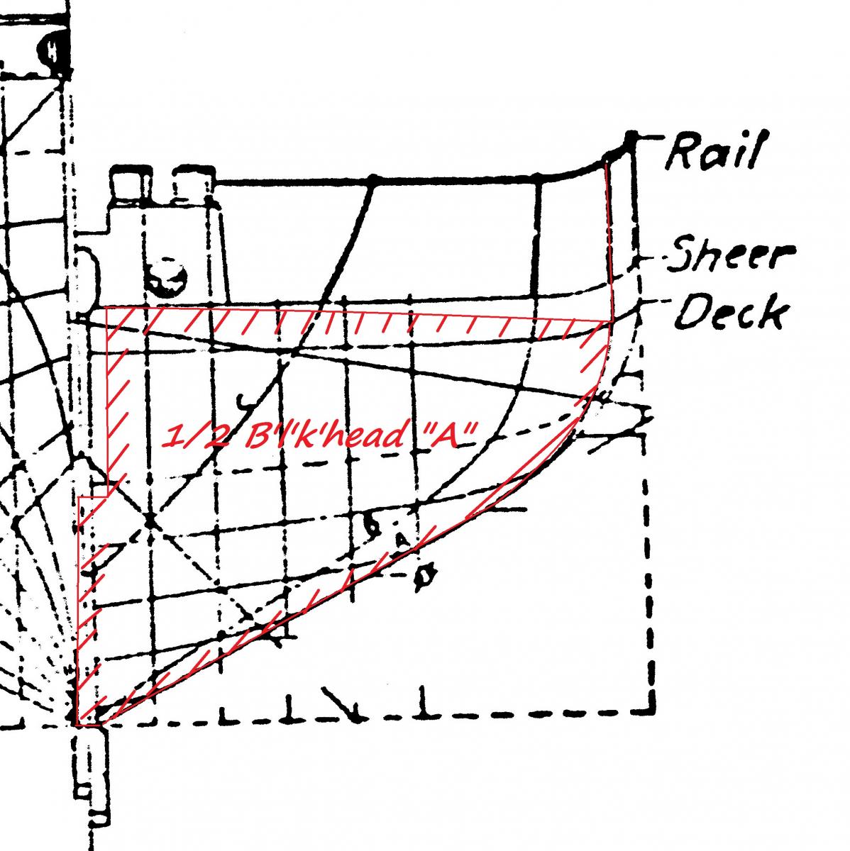
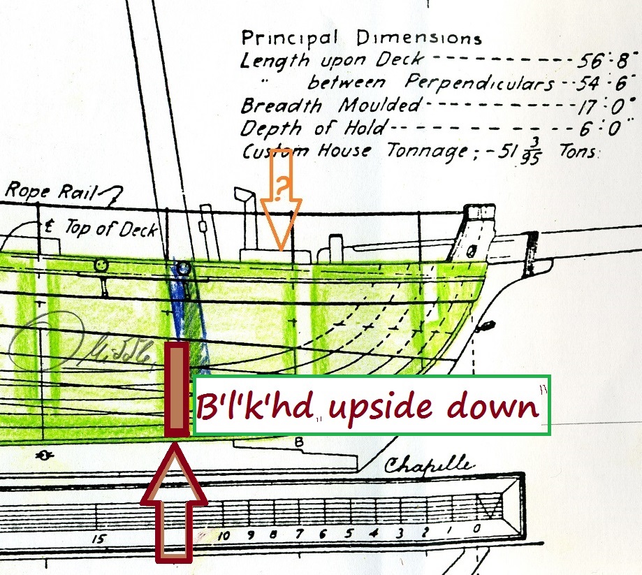
Here may be a greenhorn's solution - let's be cruel!!! So I think about shorten of the slot for the mast add some softwood all arround all the rest of length under deck to fix it propperly... and may be the most tricky idea let's turning arround the construction concept for the one B'l'k'head "A" so it is to be put in from Australia... I hope it'll worl because the edged between B'lk'head and Backbone are filled with an pice of wood already... as tried in "Ranger" to force the B#lk'h'ds in rectangular order.


-
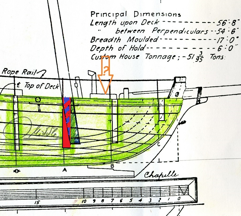
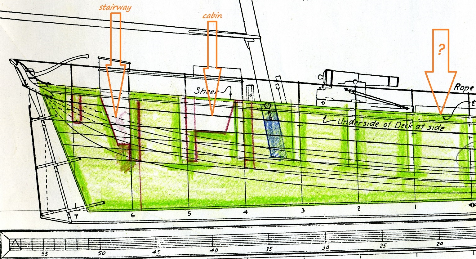
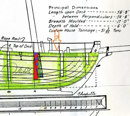
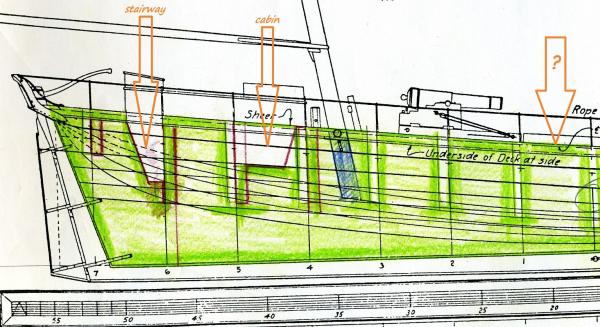
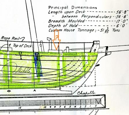
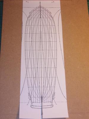
Here my drawing for the baseboard/backbone: now with a better crystal measurement in the scanner. I already figreured out to need - a staircase - room under the skylight - slots for the masts but do I need - the illusions of holds under the main hatch - a oven in the room under the galley hatch? both with a orange "?" inside the arrow What do you think? Edit: I think the worst problem is the mixture of sectionslot "A" and the mastslot!!! Still awaiting my wood...
-
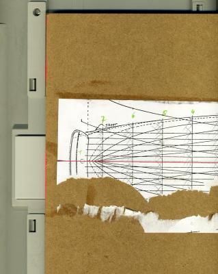
Here the Idea of the scale invented by my scanner :-)
-
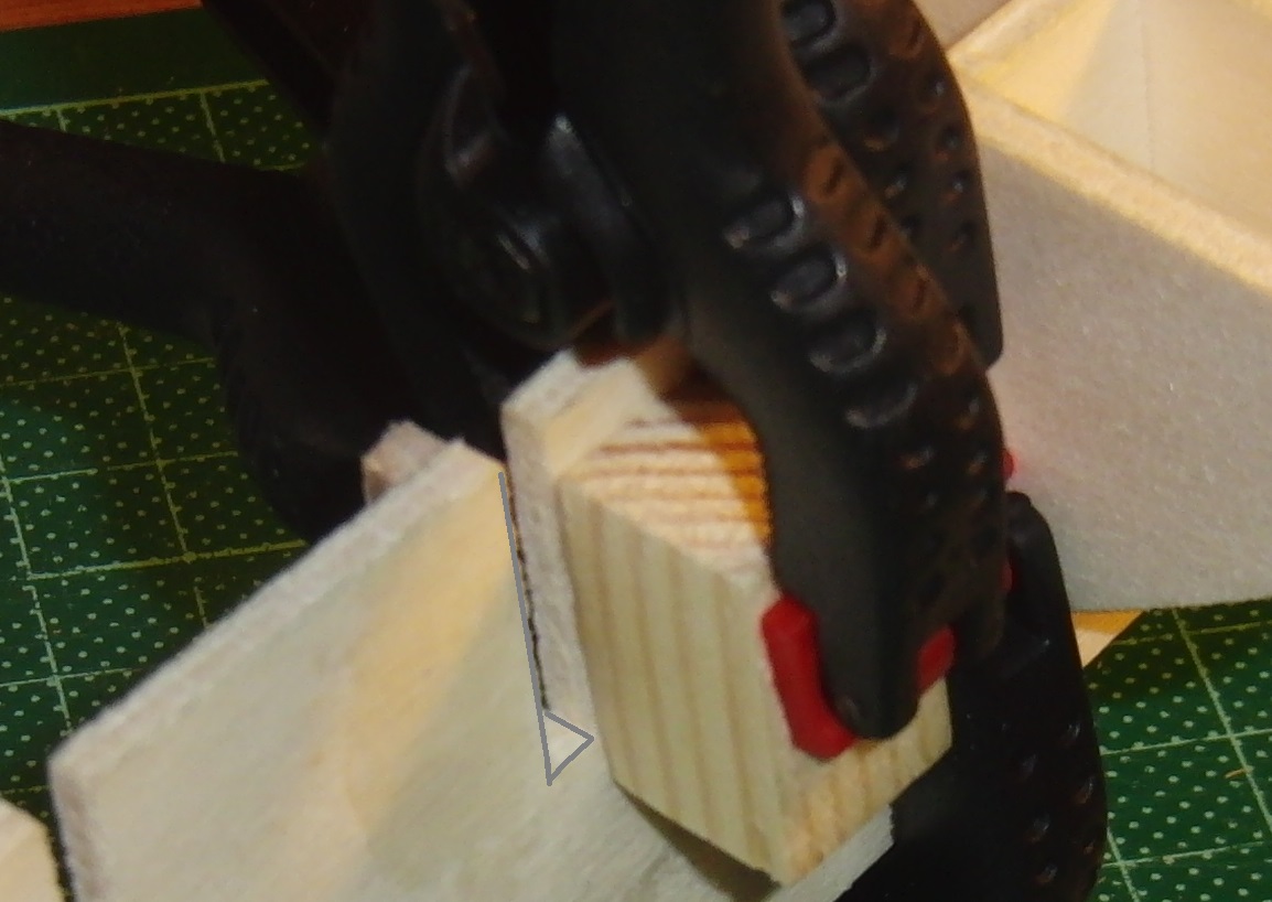
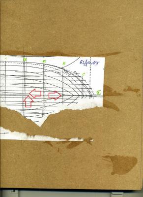
Deconstructivism!!! The copies wer'n't mirror-inverted So I stript off the portside and as I have done I got the idea to documentate it for you - so I was forced to add the red arrows in the scan to show the failers more clearly....As I haven't got a scriber I used a cutterknive for scribing. (The DigiCam doesn't still want to work - so I put the basebord brutally in the scanner! Edit this makes fun )
-
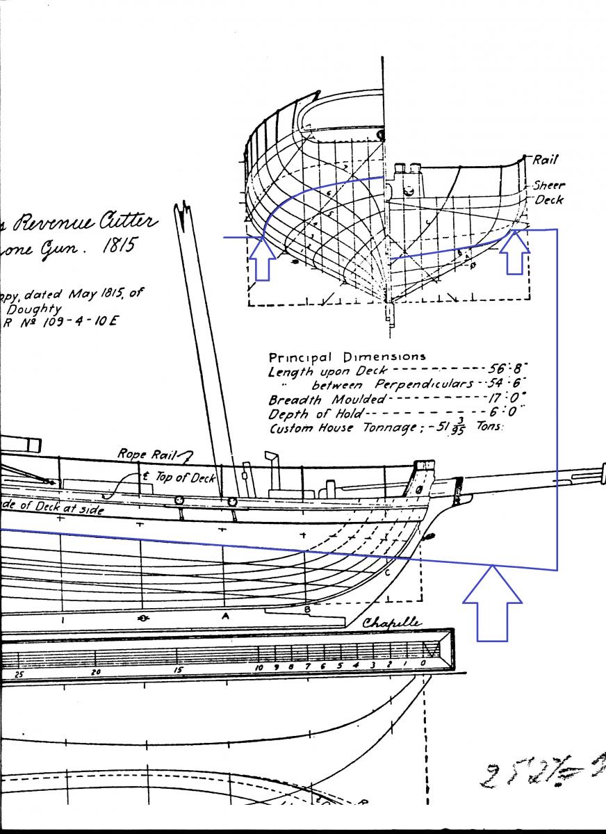
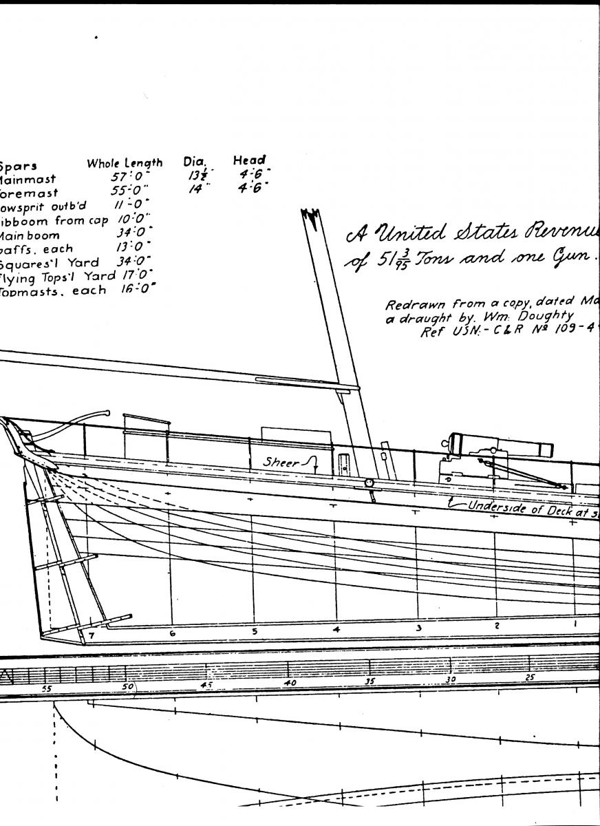
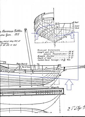
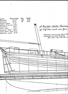
Hy to all of you - the discussion with Wayne brought me to be very conservativly and caused by this the Projects names sounds now very stiff and wooden: U. S. Revenue Cutter of 51 3/95 tons 1815 constructed by Doughty, William drawing by Howard I. Chapelle
-
1st pic: Stupidly cutted off my scaling ruler on the top of the papers...
-
Hy, managed to catch in the "e(lectric) bay" a dozen slats of 4m/m birch plywood 500 x 500 m/m and a hand full of 4m/m Aucoumea klaineana plywood 1000 x 300 m/m for the backbones paying no p&p :-) in Germany. And so I added four slips of fine pear veneer 450 x 300 x 0,55 m/m adding to the plankings stripes I'd had allready bought for the kit. But wood is painful expensive... So I can start for not a 100 Euros payed for wood for more than four ship's hulls - I wouldn't get a single kit for this.
-
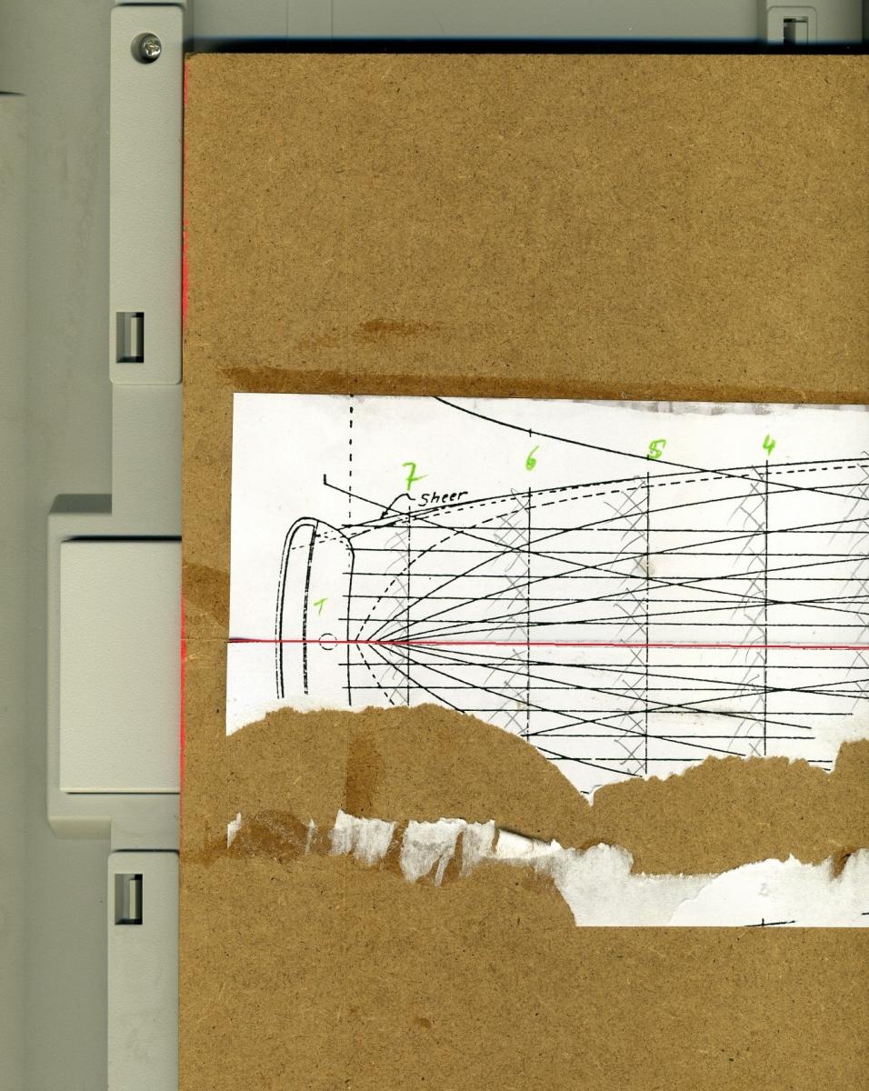
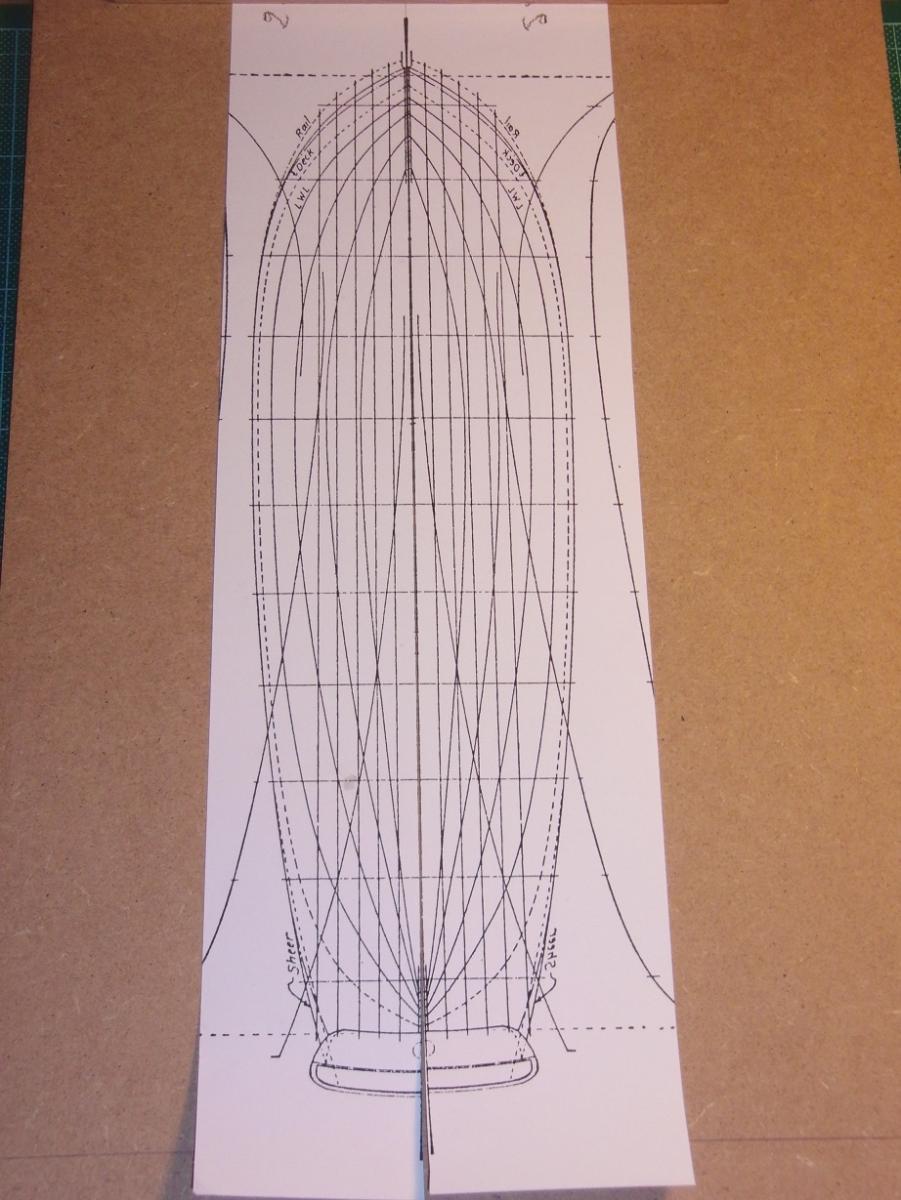
Thanks to all of you - I'll begin with somethine quite primitive... the building yard board. Just glueing the waterline and inverted waterline drawing together to know where the sections have to been put. But this'll be tomorrows work. What would be the best plywood thickness to buy fore the backbone and formers-bulkheads?
-
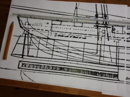
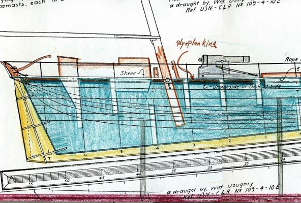
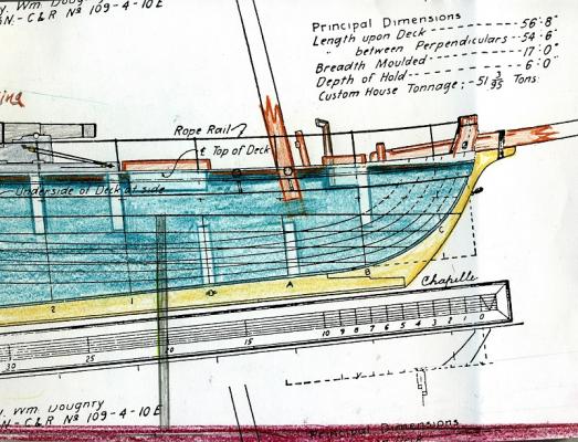
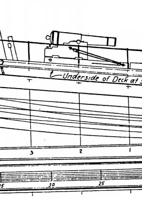
The large back gives underwater a longer rudder with certainly a larger area. Able to force the aft of the cutter in the wanted direction. Back from the copy shop I can scan for you what I got scaled to 1/48. The sections and the gun are originally 1/48 - the rest is reduced to 40%, sorry for this. I found some interesting details in the plan like the gun's circle rail is from copper. But I couldn't figure out the gun - so I add a scaled draing for our ordonance specialists. I'm awaiting your comments highly interested.
-
Thanks Eamonn - she is really a beauty - wait for the pics coming next... that's a honey! Geetrings to the Greenest Island -> !!!
-
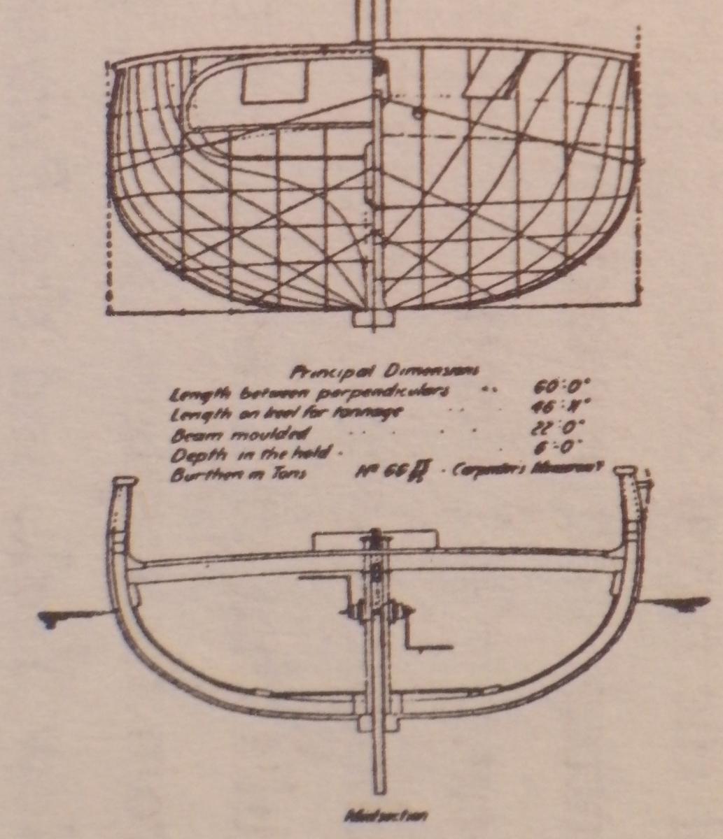
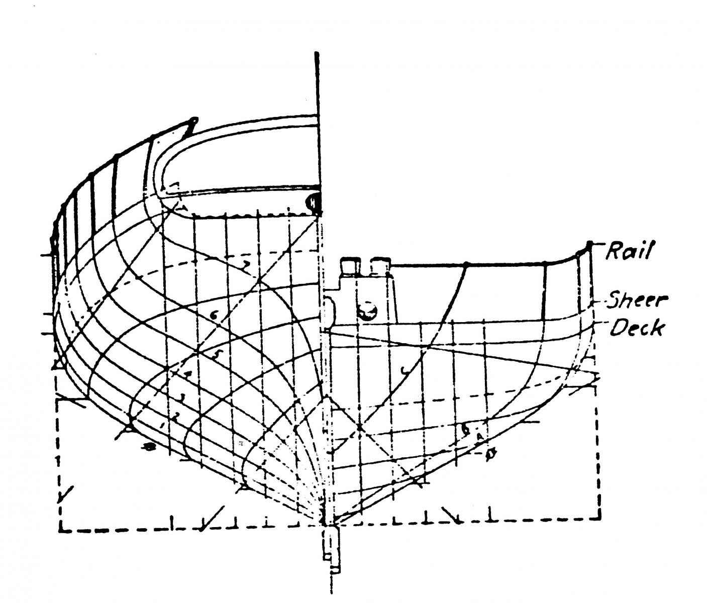
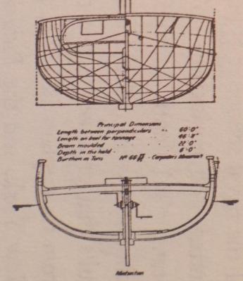
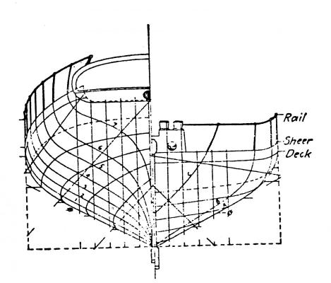
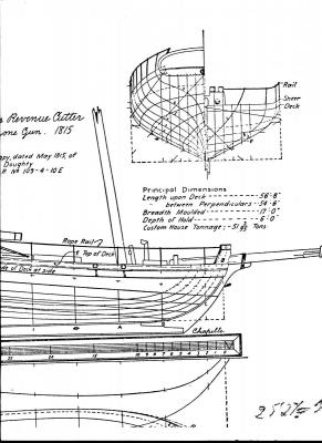
Dear friends, as I proofed my Corel-kit being an abbreviation of a 51 3/95 tons Revenue Cutter scaled to 1/64 (instead of the 1:50 advertised on the box's cover!) with an overstreched bowsprit to give it a goodlooking Loa in the sizelist I'm disappointed of the kit! So I go ahead foreward to the original drawing of Howard I. Chapelle in hin famous book: "The History of the American Sailing Ships" page 193. There we can find a propper drawing of the 51 3/95 tons Revenue Cutter (see below). And there will be a plenty of stupid beginners questions like: What material is perfect to fit the requirements of these or those part. So I'm going to start the 1/48 scratch parallel to the 1/64 kit. Hopefully you like it - meenwhile I'm going to my copyshop to enlarge to books drawings up to 1ft = 6,35m\m . Than I'm going to scan the pictures and give you a list of detailled booksides to find them in your public libary arround the corner.


-
Wayne, during the next days I've to help my wife (she fall on the iced pavement with her backbone muscel right on the stone edge ) so I can help to put your Ranger out of the shelf by doing further worknext week - so I hope! Don't give uop the ship!
-
Hy Wayne, could you do any progress with your "Ranger"?
-
Certain' - you're welcome!