GaryKap
-
Posts
276 -
Joined
-
Last visited
Content Type
Profiles
Forums
Gallery
Events
Everything posted by GaryKap
-
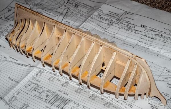
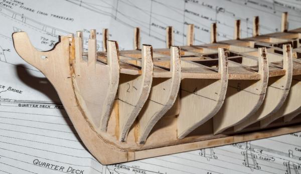
 Ken, thank you for your comments and support. I am also using your buildlog extensively. I am still in the process of “fairing” everything while figuring out my next step...the gunports. I will follow your lead and make them 3/8 square. The plans show the bottom sill of the gunports as 3/16 inch above the deck. Is that accurate, or would I be better off constructing one of the cannons and making sure? I would attempt to have the center of the cannon barrel in the center of the gun port, making allowance for the decking under the cannon. Fairing the inside of the bulwark stanchions is proving to be a demanding job. My work plan is to install the gun port framing, then the waterway, and then the cap rail. Does anyone see a problem with this? I have attached some pictures to show progress to date. One “heads up” for future Fair American shipwrights – the wing transom does not sit at an exact 90 degree angle with Bulkhead 16 due to a small error in the laser cut center keel (aka bulkhead former). This effects the filler blocks and also the stern frame installation. Check it and fix it before you glue it in! Now back to the sanding... <<Gary>>

- 206 replies
-
- 2
-

-
- fair american
- model shipways
- (and 1 more)
-
Bob - Thanks for your kind words. I am using your build log as my "practicum". Yes, the bulkheads are plywood. It is both good and bad. There are more spaces in the middle layer of the plywood than I would like. I can use wood filler to plug the holes, but it provides little to hold the planking. On the other hand, the bulwarks are stronger this way than if cut from basswood. I am in the process of fairing the hull and adding the additional bracing between bulkheads as you and others did. Also trying to figure out how to construct the stern assembly. I had two semesters of mechanical drawing in high school half a century ago, but I still need to really study the ships plans. I figured out that if I put the brass pedestals recommended by Model Shipways under bulkheads 6 and 10, the waterline is very close to level. I drilled the appropriate holes and will add additional wood to both sides of the bulkheads here. Seems to me this is better done before planking the hull. I found some excellent history on Fair American in the book "On Seas of Glory" by John Lehman. He calls the ship a "maker of fortunes" and describes her privateering adventures. Back to the sanding. More to follow. <<Gary>>
- 206 replies
-
- 1
-
-
- fair american
- model shipways
- (and 1 more)
-
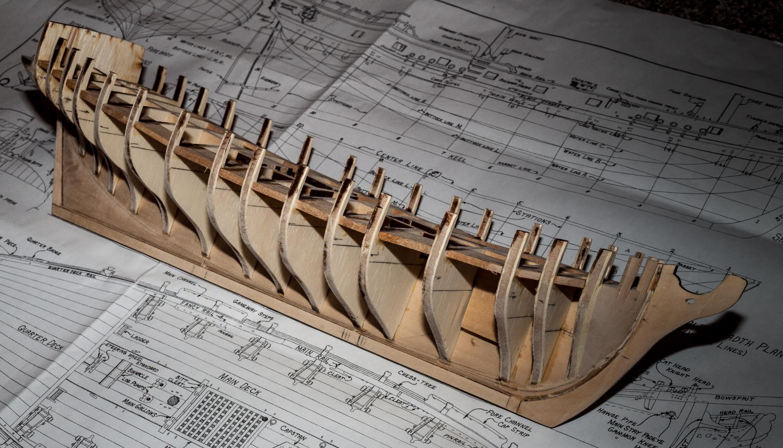
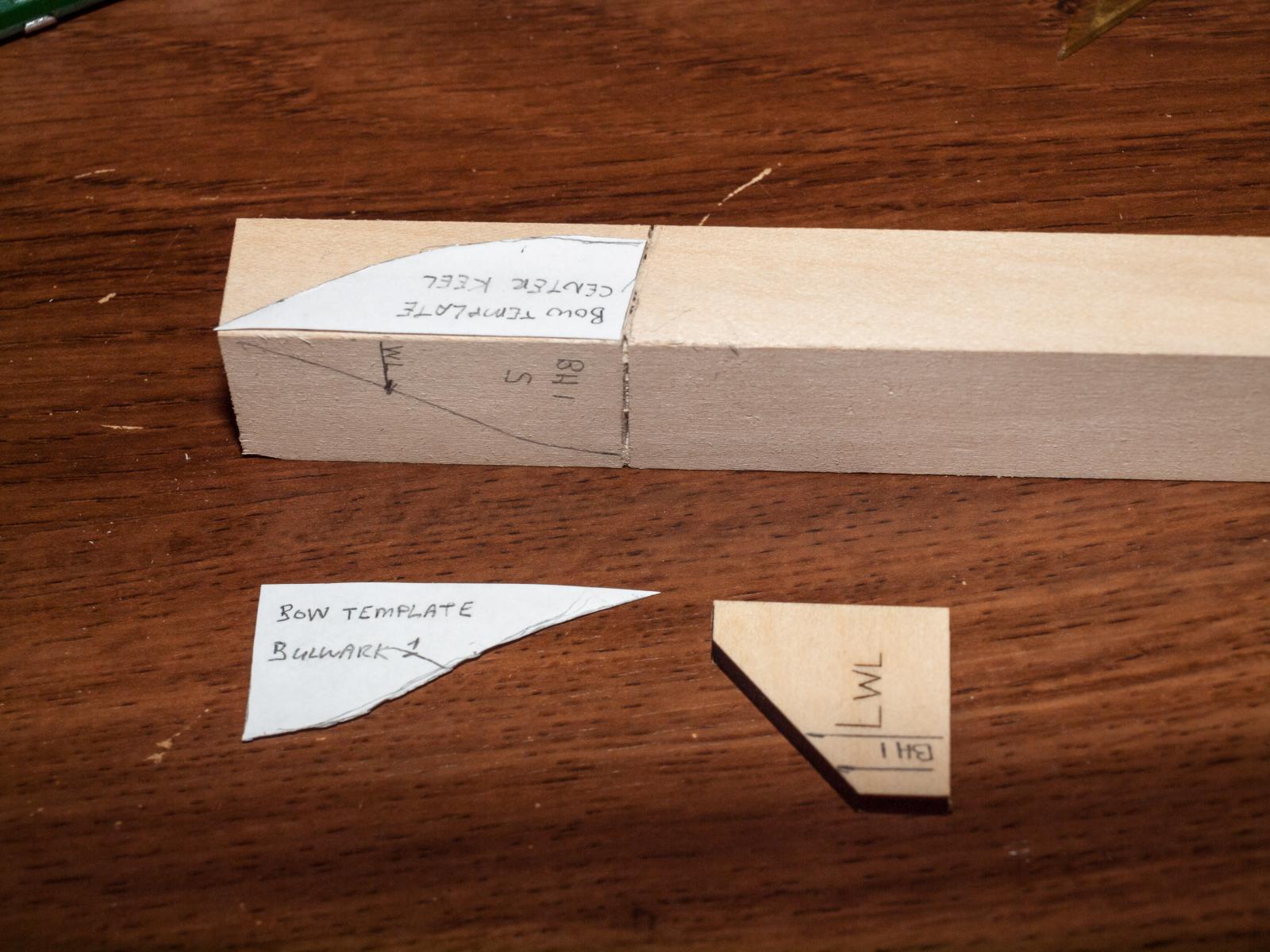
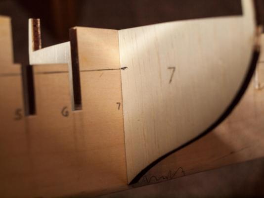
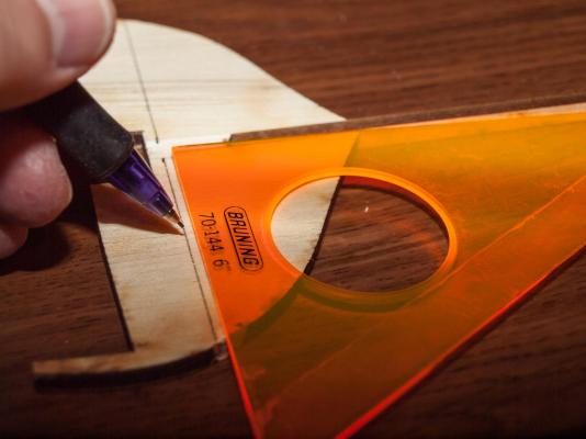
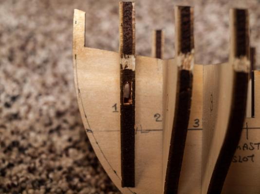
The planking book (Ch. 2) details the importance of the water line as a reference for establishing the location of the main wale. I placed the center keel over the sheer plan on Sheet One and carefully transcribed the water line on each side. Then I extended this line to both sides of each bulkhead, using a drafting triangle to insure a proper alignment. This gives me the location of the waterline along both sides of the hull. I can then measure distances on the plan from the waterline to the bottom of the wale for each bulkhead and transfer this information to the hull. To help in shaping the bow filler blocks, I photocopied parts of the plan that provided templates along the center keel and bulkhead # 1. Even with these, the job was more of a challenge than I envisioned.


- 206 replies
-
- 3
-
-
- fair american
- model shipways
- (and 1 more)
-
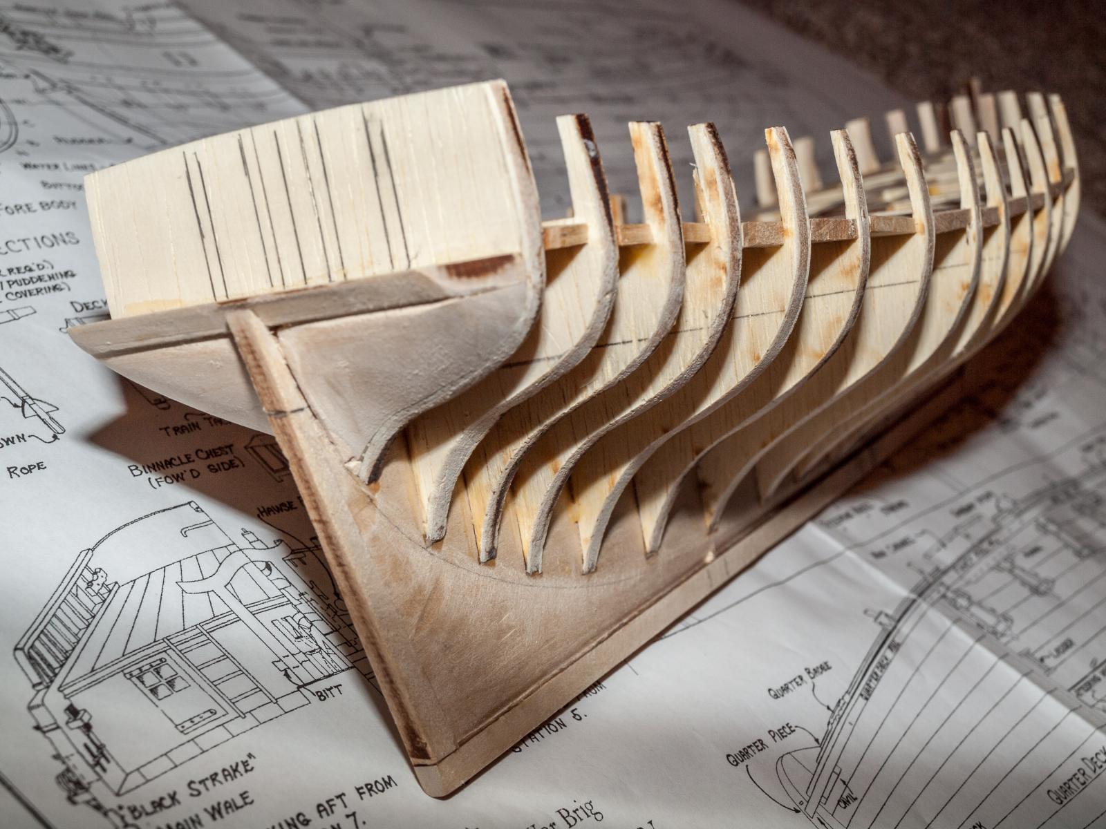
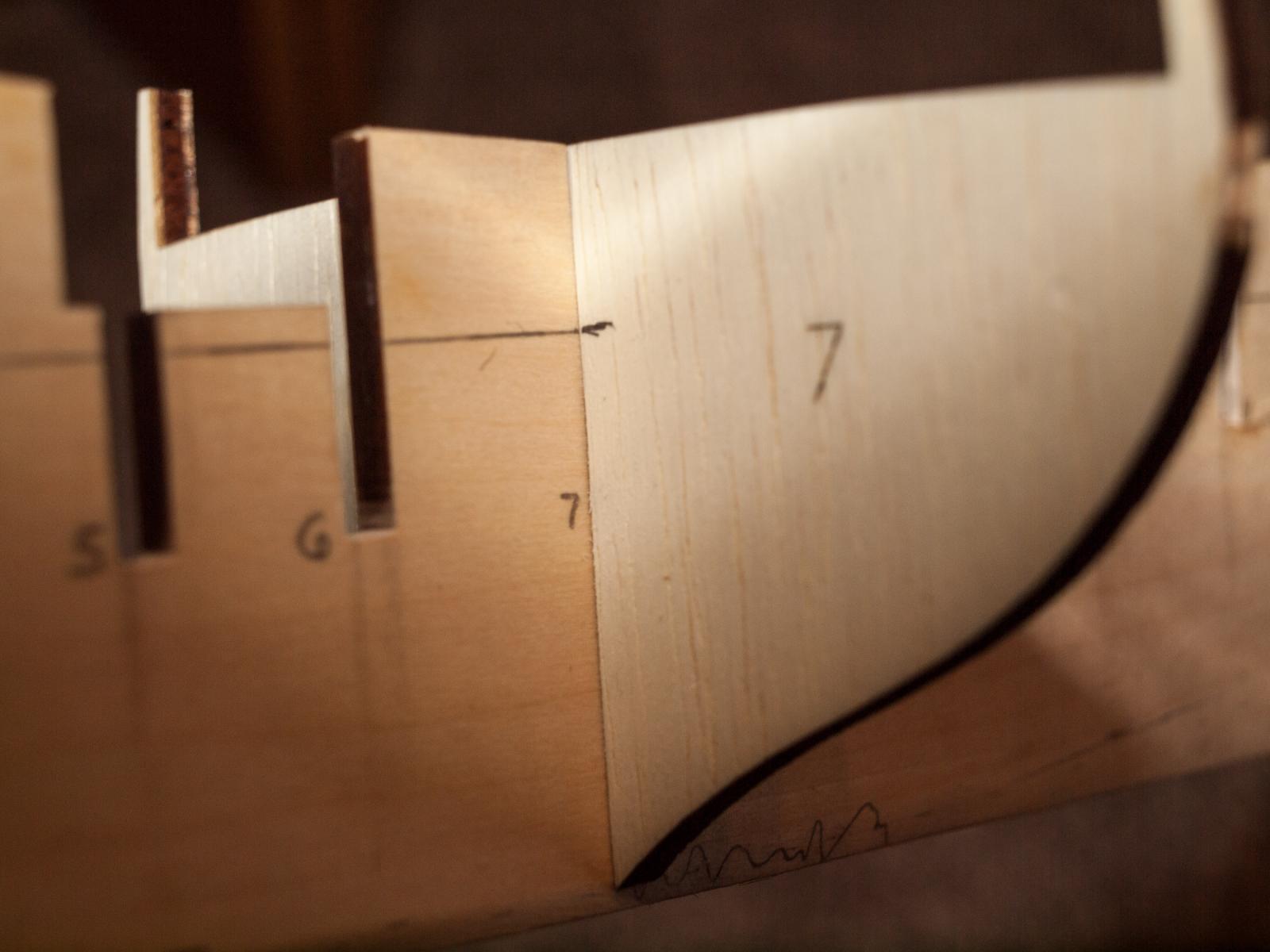
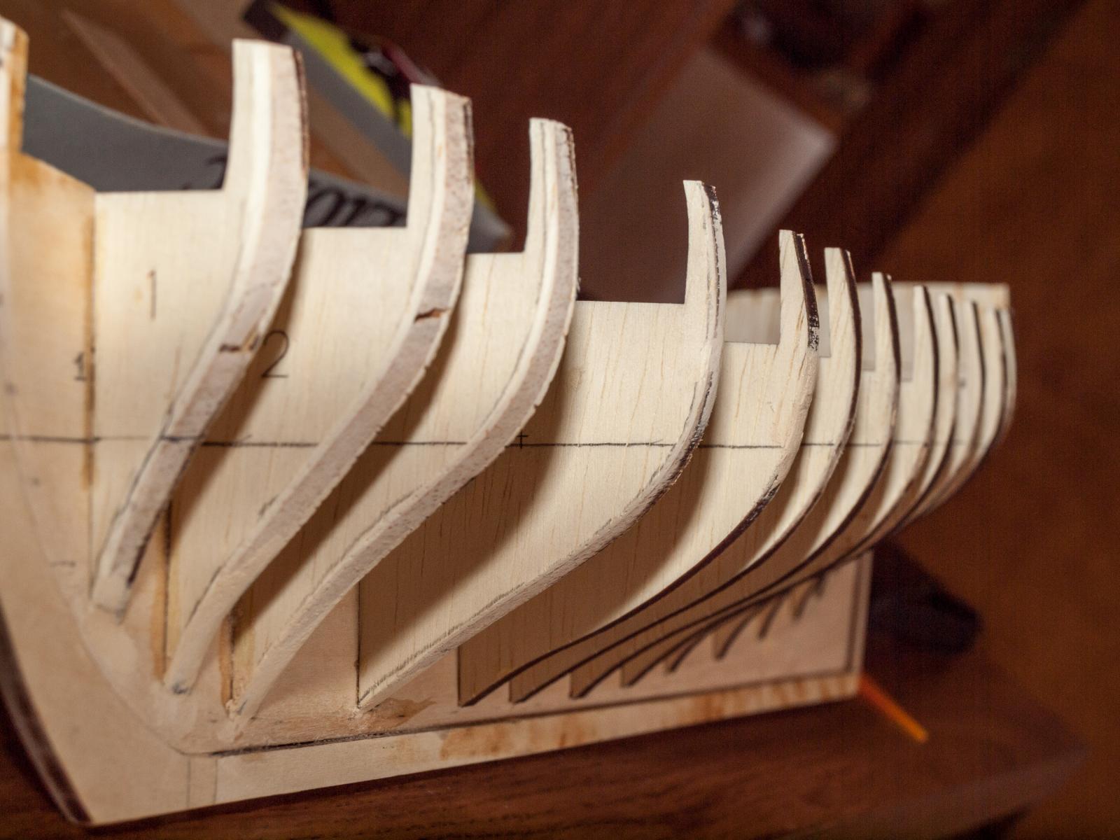
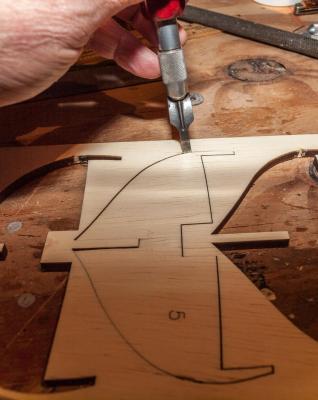
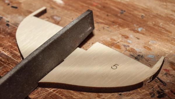
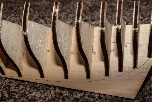
This morning I “extracted” all bulkheads from plywood sheets “B” and “C”. To do this, I had to cut the small uncut segments holding the laser cut bulkheads. The best tool I found to do this was an EXACTO chisel blade 3/16 inch wide and as sharp as I could get it. I quickly discovered that all of the slots in the basswood center keel were slightly too narrow (by about 1/32”) to accept the bulkheads. My work-around was to use the narrow edge of a large flat file to narrow just that portion of the bulkhead that would have to go in the slot. After I dry – fitted all of the bulkheads into the center keel, I inspected the results. All bulkheads are flush with the top of the center keel in what will become the deck surface. I am a little concerned that bulkheads 10 through 14 do not come close to the bearding line. Should I re-draw the bearding line to touch the bottoms of these bulkheads and taper the center keel accordingly? Another concern is with a defect in the plywood for bulkhead # 1. There is a gap in the middle layer that would run horizontally and be 1/8 inch wide and 3/8 inch high. I could probably find a small piece of wood and glue it in. Or is this something where I should request a replacement from Model Expo? Thanks for stopping by. Let me know your thoughts and recommendations. <<Gary>>
-
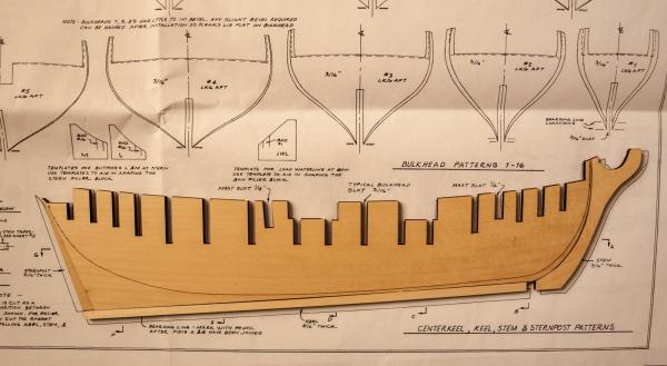
Russ - Thank you for your reply. I must not have stated the problem clearly. The actual wooden parts do not fit properly against each other. As shown in my photo, there is a gap of a quarter inch between the front end of the keel and the bottom / back of the stem piece. I suspect Model Shipways may have a new pattern for their laser cut parts in response to complaints shown on other build logs. My center keel (what you call the "profile former" is one single piece, but is shown in the plans and on other build logs as two pieces that must be glued together. So I think Model Shipways made changes to the kit very recently as reflected in my kit purchased in October. But they still don't have it right because now the keel is too short. You are right - either I contact Model Shipways and request a replacement, or try to correct it myself. I think first I will extract all of the bulkheads and make sure they fit properly and go from there. Time to go celebrate - Happy New Year everyone! <<Gary>>
-
This will be my first POB model. During the past year I completed the solid hull version of the Model Shipways Rattlesnake. I made a lot of mistakes but learned a lot and acquired some skills in the process. I selected Fair American for my next project because I like the size and appearance of the model, as well as its relatively simple rig made even easier by the larger quarter inch to the foot scale. I am a bit nervous about the hull planking – especially the lower hull. But I have read and re-read the planking books and tutorials, and studied the build logs on this site. I am very grateful to have access to these. My “plan B” if I mess up the planking is to get a big bucket of plastic wood and some sandpaper... I have checked the parts list, and the only thing that seems to be missing is the small dowel for the flag staff (part WP5100-06). I noticed other build logs reporting that the center keel did not line up with the plans. Mine pretty much did – but my kit has the center keel as one piece; not the two described by others. I extracted the center keel, keel, stem, and sternpost from Wood Sheet “A”. When I placed them together, I discovered that the keel is approximately ¼ inch too short. Notice in the photo the gap between the stem and the keel. I will most likely just cut a small piece of wood to fill this unless any of you has a better suggestion. <<Gary>>
- 206 replies
-
- 1
-
-
- fair american
- model shipways
- (and 1 more)
-
Are the jibboom and flying jibboom guys / guy pendants part of the standing rigging or running rigging? (this would be for RATTLESNAKE again). Also, the plans say they are "set up with single blocks and tackle hooked to eyebolt in bows". How large would these blocks be for a ship of her size (~90 feet)? Perhaps a more basic question...what is the purpose of the guy pendants? Any help that Forum members can provide will be appreciated. Thanks <<Gary> p.s. The reason for asking is that the Model Shipways Instruction Manual lists them as STANDING rigging (p. 33) as do the old texts on rigging. However, some of the Internet photos of completed RATTLESNAKE models, both MS and Mamoli, show beautifully crafted ships with the jibboom guys in tan, indicating running rigging. I can see that many folks on this forum are sticklers for detail and authenticity, and was hoping for some resolution as to which is correct. And I would still like to understand the purpose and function of the jbboom guys.
-
Rattlesnake rigging help, please - moved by Moderator
GaryKap replied to GaryKap's topic in Masting, rigging and sails
GREAT find!!! If you are even halfway serious about the running rigging, you will discover that there are LOTS of lines that need to be belayed...and belayed in their proper location. So the options are to use shroud cleats, install pin rails in typical places, or do less of the running rigging. I plan to put pin rails along the bulwarks, and use the Petersson book to determine appropriate belay locations for the lines. My old Model Shipways plans have other problems. The rigging plan shows the fore topsail braces and fore topgallant braces going to double blocks on the mainstay and main topmast stay respectively, then straight down to the gallows bitts near the chimney, where they go through sheaves and are belayed to cleats. The problem is that the spare topmast and topsail yard that sit on the gallows bitts and support the longboat are directly above the sheaves for the braces. So I need to figure out a work-around for that as well. <<Gary>> -
Rattlesnake rigging help, please - moved by Moderator
GaryKap replied to GaryKap's topic in Masting, rigging and sails
Well, Martin, that raises another question. In Chapelle's book "History of American Sailing Ships" he discusses Rattlesnake and wonders whether the ship actually had those removable gangways. He doesn't show them in the drawings in his book that presumably came from the Admiralty data. I have chosen to build my Rattlesnake as shown in the drawings - without the gangways. http://www.awiatsea.com/images/Rattlesnake/Rattleiso.jpg Before I retired, I worked with mathematical models and was always haunted by the famous quote "All models are wrong, but some are useful". (George E.P. Box). I think the same philosophy applies to both statistical models and ship models. But what does Harold Hahn show in his plans? <<Gary>> p.s. I made a PDF scan of the pages in Chapelle's book but I'll be darned if I can now find it on my hard drive. The link above is to one of the Chapelle illustrations. (notice his name under the bow) -
Rattlesnake rigging help, please - moved by Moderator
GaryKap replied to GaryKap's topic in Masting, rigging and sails
Thank you for the additional information and the photos. Here is another question. The Campbell rigging plans do not show any pinrails along the bulwarks on Rattlesnake, but contemporary similar vessels do appear to have them. In the absence of pinrails, Campbell relies on shroud cleats to belay many lines. But this is only guesswork on George Campbell's part, isn't it? What do Harold Hahn, Mamoli, or current Model Shipways plans show? (This question is self-serving - it would be FAR easier for me to retrofit pinrails than to try and attach shroud cleats at this point ) <<Gary>> -
Rattlesnake rigging help, please - moved by Moderator
GaryKap replied to GaryKap's topic in Masting, rigging and sails
Hi Martin - Just to be clear, my Rattlesnake build is a solid hull Model Shipways kit from the early 70's that I purchased on eBay. So I am working with George Campbell's rigging plan. He shows the crossjack braces, mizzen topsail braces, mizzen topsail lifts, main topgalant braces, and fore topsail lifts belayed to shroud cleats. The rigging plan has a sketch of a shroud cleat attached to the shroud with seizing. Campbell says shroud cleats were "fitted on all lower shrouds above the deadeye". I am guessing immediately above or within reach of the seamen. Can you point me to where David Antscherl describes making shroud cleats? The blocks that came with my kit are none too good. I look with envy at the ones Chuck shows on his web site. Wish I had known about them before I started rigging... And crowsfeet? The Campbell plans do not show them at all. I was only made aware of them on this web site. Now if I could only get the Super Glue nozzle to stop clogging up.... Tomorrow we have a weather forecast for freezing rain, so it will be a good day to stay indoors and work on rigging. <<Gary>> -
Rattlesnake rigging help, please - moved by Moderator
GaryKap replied to GaryKap's topic in Masting, rigging and sails
Hi Martin - Yes, that is what I finally figured out as well. I have rigged the topsail halliard and the fore topsail halliard, and seeing it in "3D" makes perfect sense. The halliards straddle the stays in a manner that lets the tye pull straight down and not to one side. As I work my way up the masts rigging the yards, the job is getting increasingly difficult. The kit did not supply nearly enough blocks, and also I wish I had fitted shroud cleats before starting the running rigging. And then there are my fat fingers... Yes, Peterson is a great aid. Another source that continues to help me is Chuck Parasso's excellent and well written instructions for Syren, downloadable as PDF documents from Model Expo. I will work on taking some pictures of my Rattlesnake build and putting them up. Thank you for your reply to my post. <<Gary>> -
I was able to find and download a digital PDF version of Lennarth Petersson's book "Rigging period ship models". WOW - what a wonderful resource for proper rigging. I really like that his drawings isolate very specific elements of the rigging...for example clewlines for the fore mast (p. 83). This will be a big help to me in completing the running rigging on Rattlesnake, and for Fair American next year. Now I need to find a hard copy of the actual book at a good price... Thanks to you guys for making me aware of this great publication. <<Gary>>
-
Rattlesnake rigging help, please - moved by Moderator
GaryKap replied to GaryKap's topic in Masting, rigging and sails
Craig - Thank you for your reply. I will look for the book you mention. As I think about it more, the rigging arrangement makes sense as described in the plans. It permits the tye to stay centered and aligned with the mast, and thus stay in the mast sheave. Otherwise the tye could get pulled to one side and come off the mast pulley and jam. For me, figuring out the rigging intricacies is an enjoyable part of the model building process. I continue to be amazed at the ways sailors used the mechanical advantage of pulleys to make their jobs at sea easier. <<Gary>> -
I need help figuring out the topsail halliard tye for my MS Rattlesnake. I have been staring at the rigging plan for an hour, re-reading the following paragraph: Topsail halliard Tye, from center of yard, thru sheave in mast and then to a single block spliced in the end. A runner is led thru the single block with a double block at each end. Halliards lead from the double blocks to single blocks with beckets on long strops hooked into the channels each side. And I still can't envision this. What do they mean by a "runner"? Is this simply a length of line with a double block at each end? Why would they rig it that way? Doesn't make sense to me. Any information you can provide will be appreciated. Thanks <<Gary>>