Jond
-
Posts
876 -
Joined
-
Last visited
Content Type
Profiles
Forums
Gallery
Events
Everything posted by Jond
-
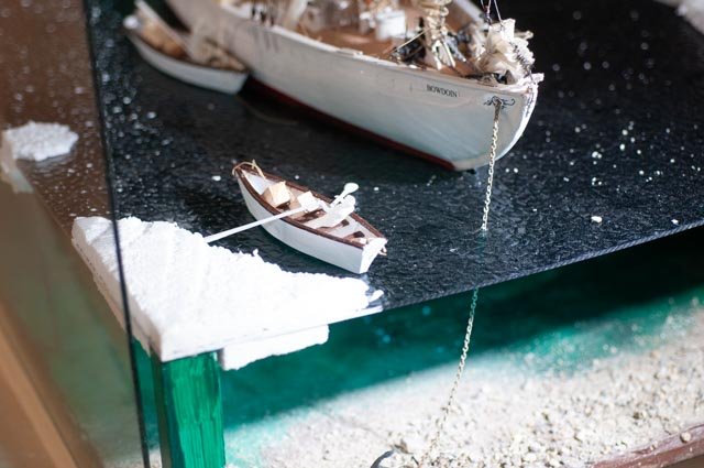
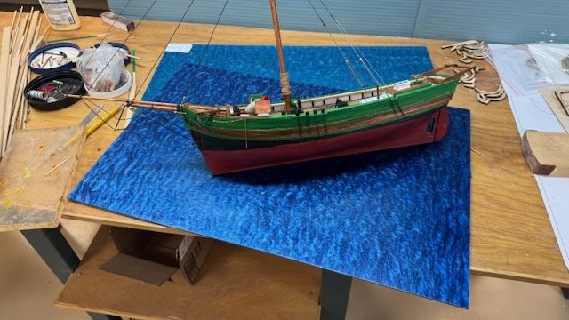
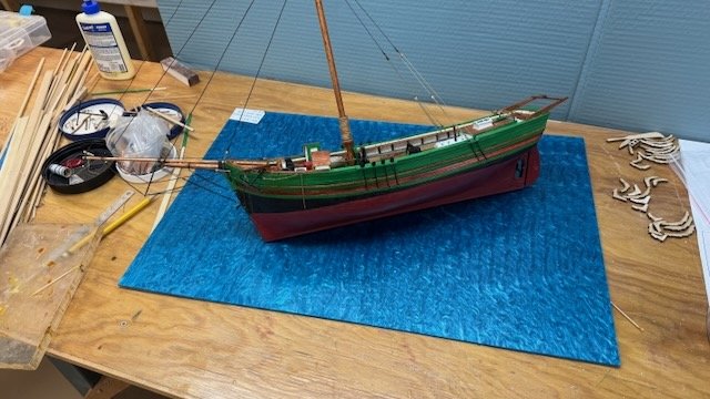
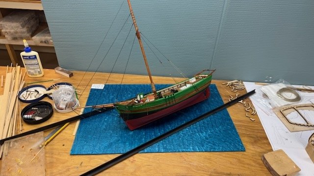
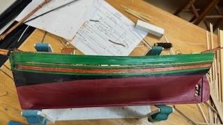
 Here is an example of the value of this forum. Both Eric and Wefalck and anyone else who would jump in.....thanks for your input. I have played around a bit and settled on a size. I cut a new sheet of cardboard 10x24 and added scrap 10 by 4+ inches just to see. That means when I cut off a 6x24 sheet of acrylic, I can do as big as 10x6 which is more than I need. If I do the joint at the stern, it runs through the boat. That is easier to hide, etc. to discuss later. The point is I will have left over 6 x 14 inches as well as the cut out to experiment with paint or even film underneath. I do not want to limit light, as an important point to me is to see below. I am also placing this scene in the cove at Gjoa Haven with relatively smooth water. My idea of the sloop being at anchor is, that it will be in shallow water ,so I will have sand below and the anchor set in the sand. I might even have fish on wires. 🤪. not.... realy... The acyclic I bought unfortunately came smooth, a surprise, so unlike my Bowdoin, shown below,I need to do something. Unfortunately this acrylic is too smooth ,so I will using various things to add some water movement too. Therefore I need also to learn about for wave highlights etc. All out of my wheelhouse. I found when planning the HMS Terror ice work , Utube is our friend, and I look there for more advice on technique and then be able to experiment. I do have a second sheet of acrylic if I mess up too badly. The acrylic I used with HMS Terror was another color. I want to save that second sheet for my next build of Fram. Here you see it went ok with ice. I did nothing to it and it looks to me as if it iready to freeze. even the reflection just off the bow makes me wonder if it is already skim ice. I will have some ice and I agree with both of you, I need to work on the water. I also want to work with the acrylic I have, so there is some new fun in my future.
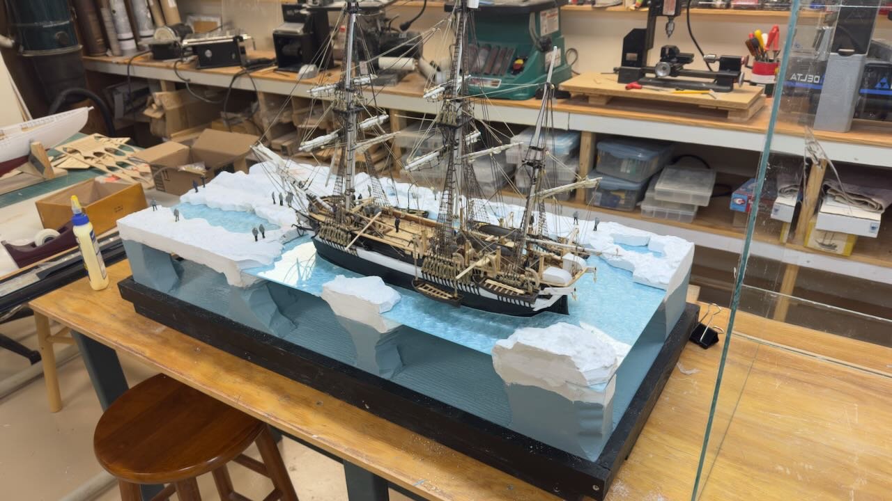
- 61 replies
-
- 5
-

-
- Northwest passage
- Norway.
- (and 2 more)
-
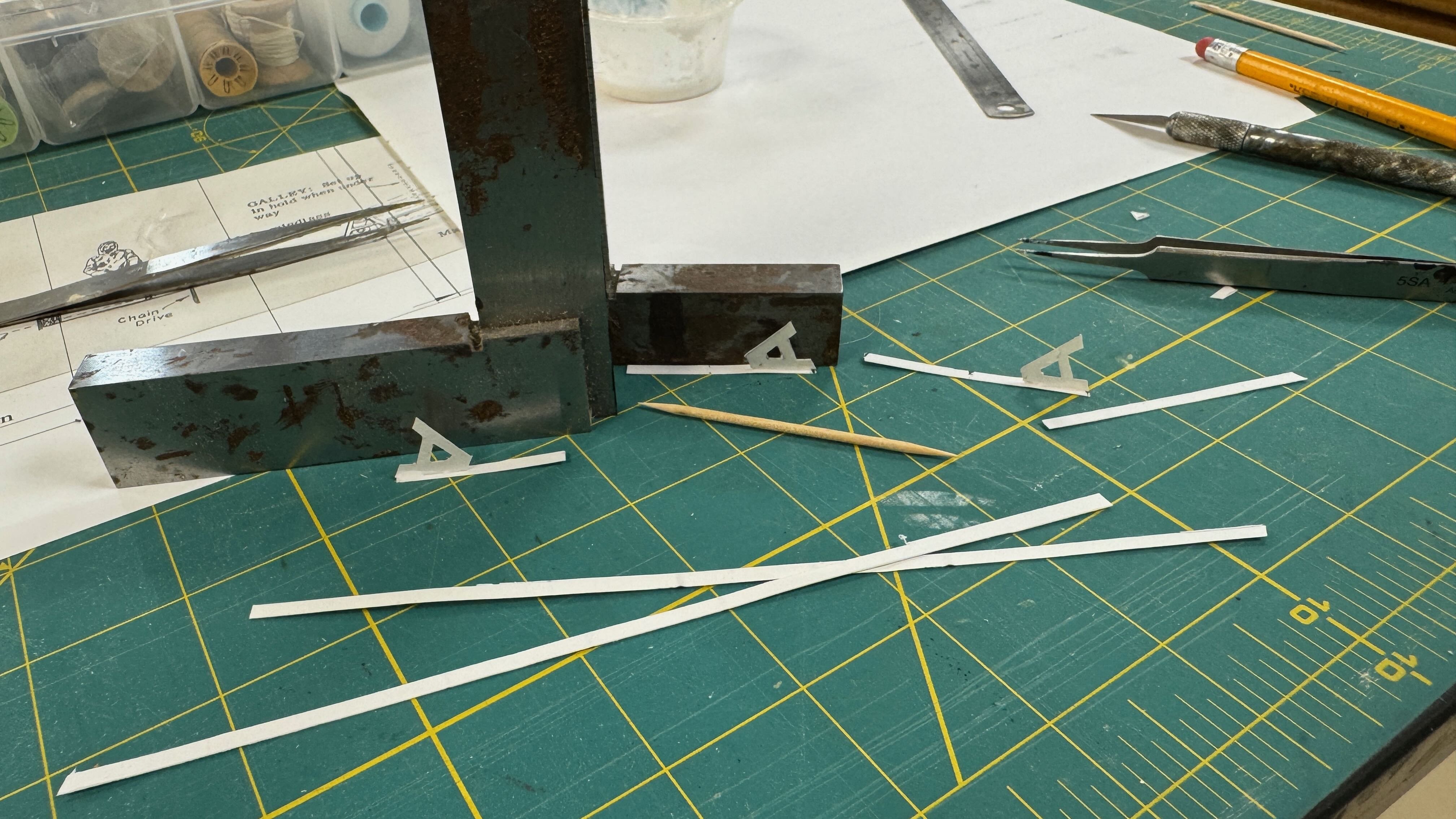
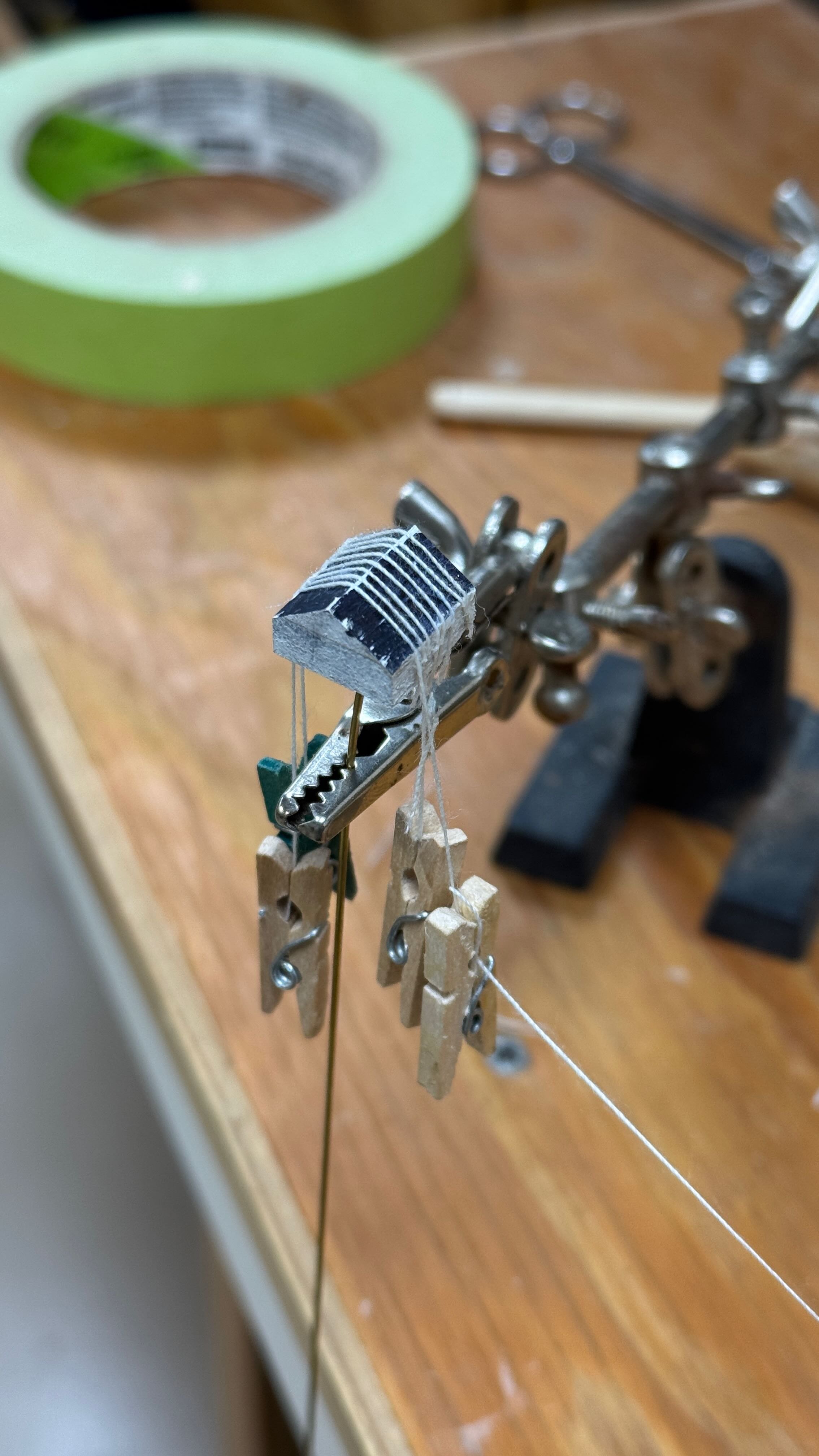
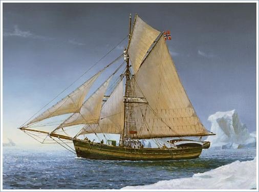
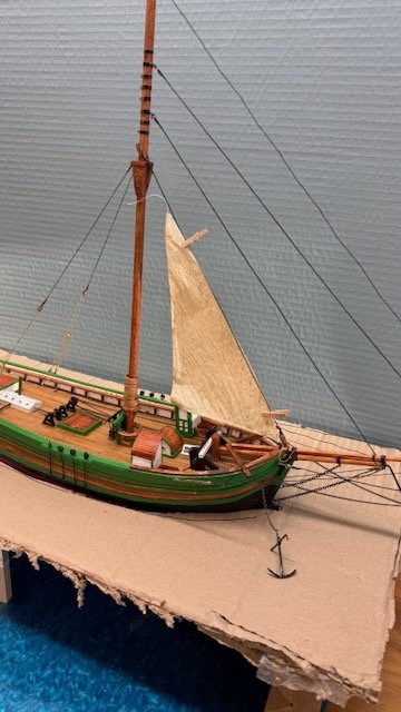
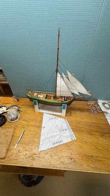
13a planning of the scene continues as I am getting the rigging underway So far, I have decided to include the main sail, and she will be in water, and not in ice. This update part a is the sails. 1-4 here are two images of progress on rigging and two at the waterline level showing the stained stakes, a propeller and progress up front. 5 here I added hoops. An issue for one to show furled sails is that sliced tape hoops are a bit big for scale. If I show the mainsail raised, I believe one will hardly notice. Hoops in scale at the 1:48 scale would be thinner than 1/32….I would buy the cut-out type that a few model fitting stores offer. I find with my thumbs; however, they are too weak to bend sails. Thus, one needs to decide by this stage which way to go. 6. here is an internet image of a painting showing her sailing away. She is cool to look at but I want to do something where she is in-between sailing and moored. 7. here I went ahead with a scrap piece of old silk span I made up a Jumbo. This is the first sail to solve as it is the most “inside”. 8-9. here I show the jumbo either flying with the paper doll mainsail flying or roughly furled. Honestly, I am flummoxed and or stuck, not sure what comes next. I think I need to make up furled jib and flying gib and take another look. All three furled may make more sense. Cheers
- 61 replies
-
- 7
-
-

-
- Northwest passage
- Norway.
- (and 2 more)
-
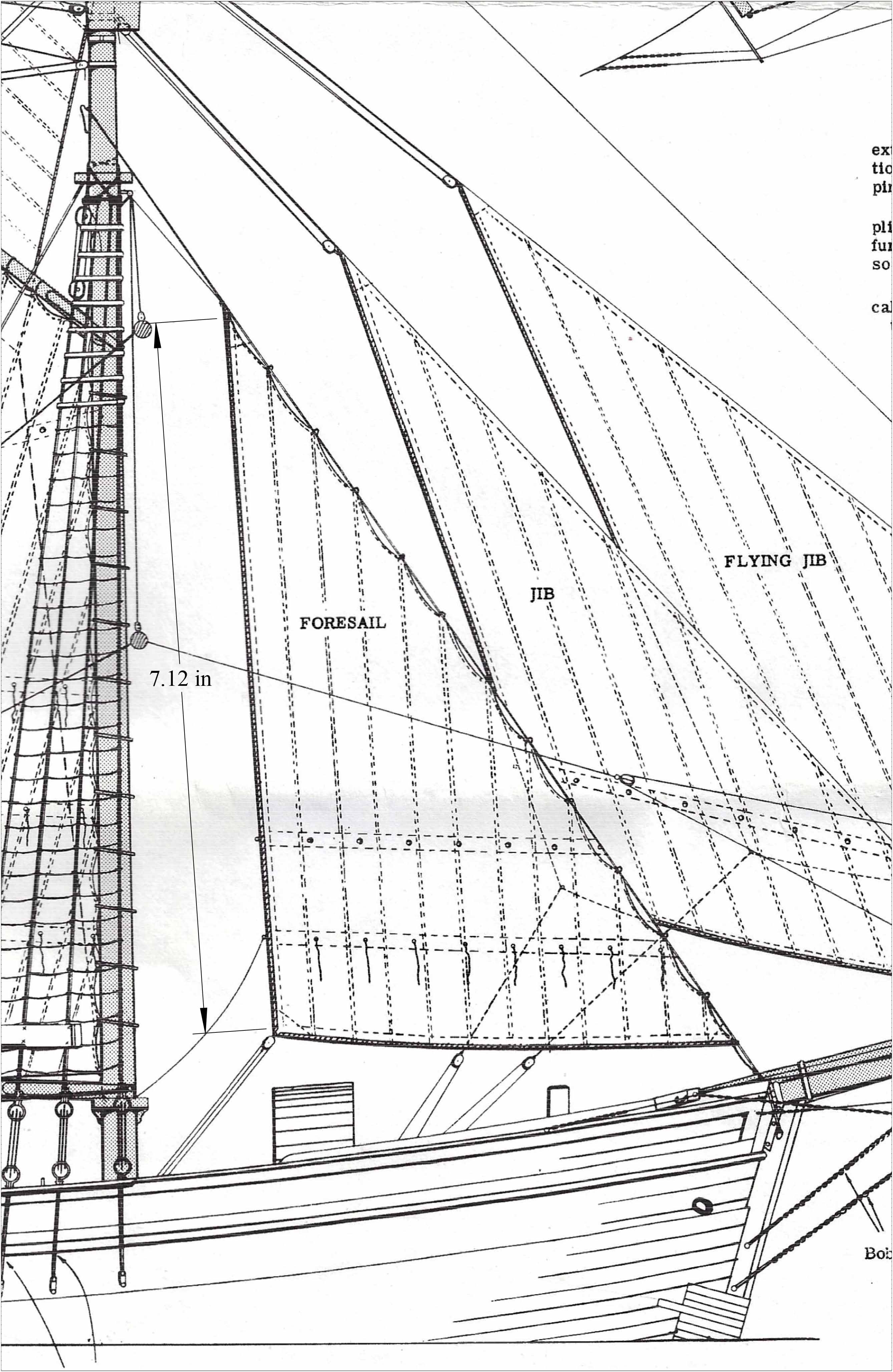
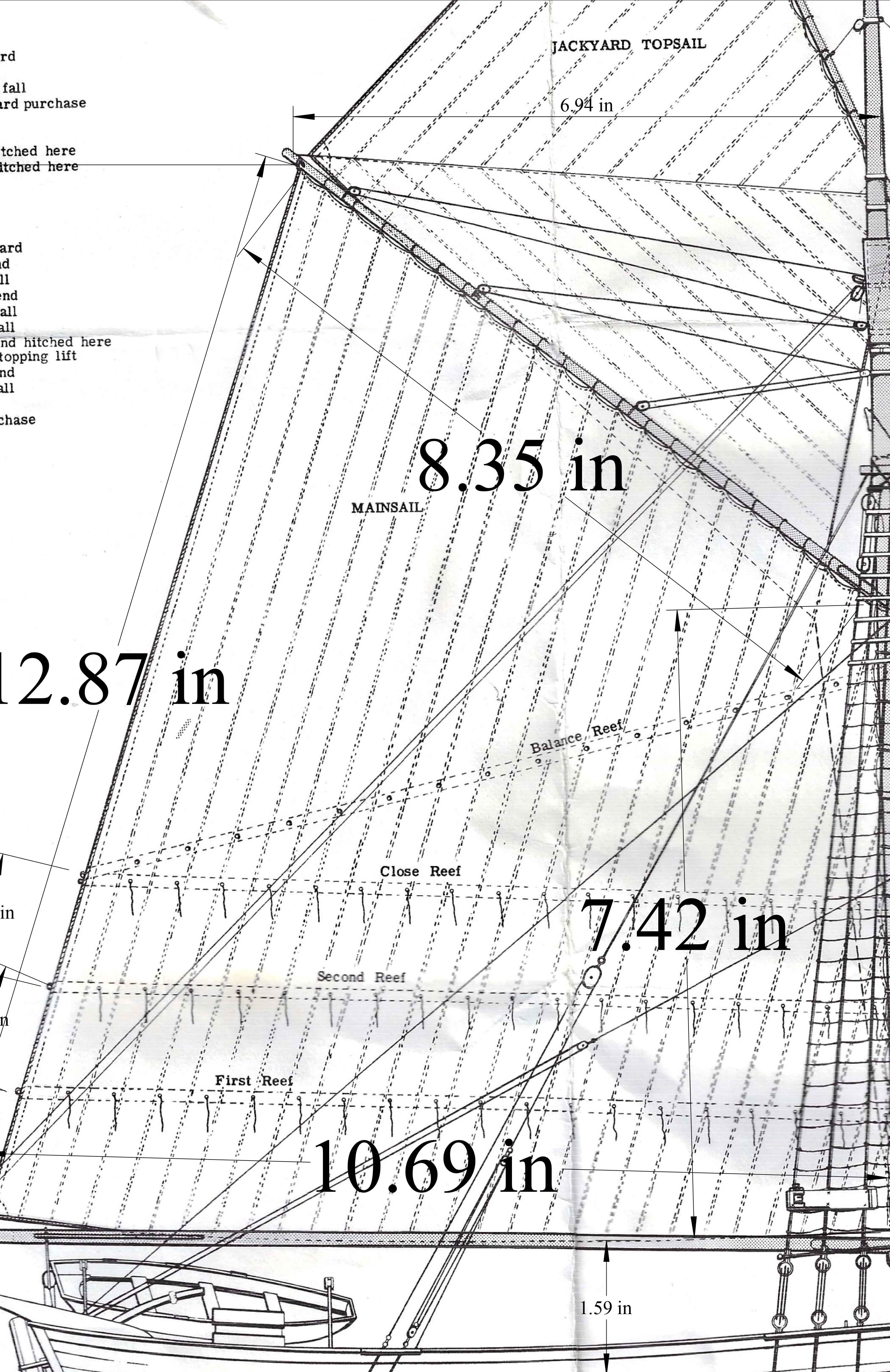
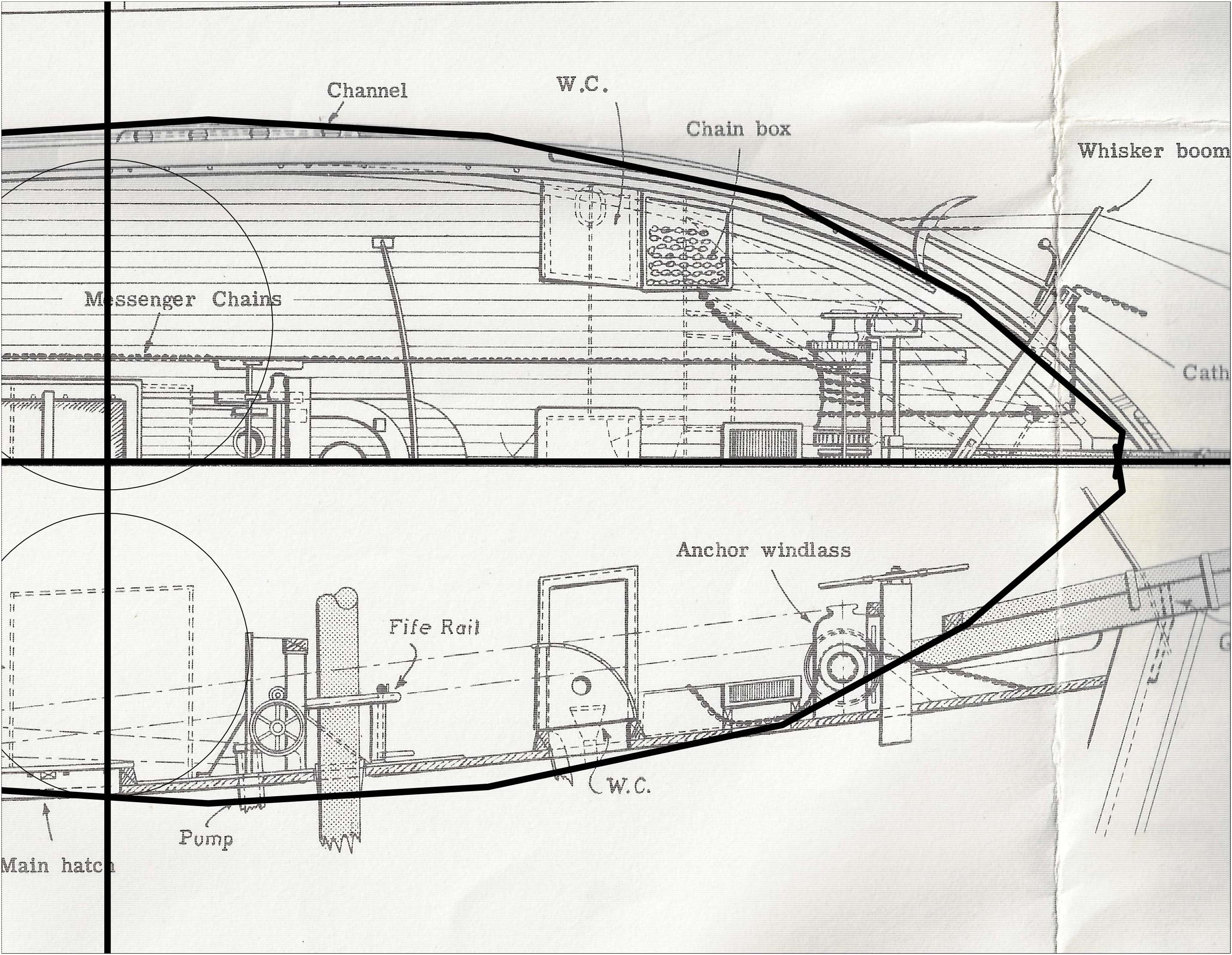
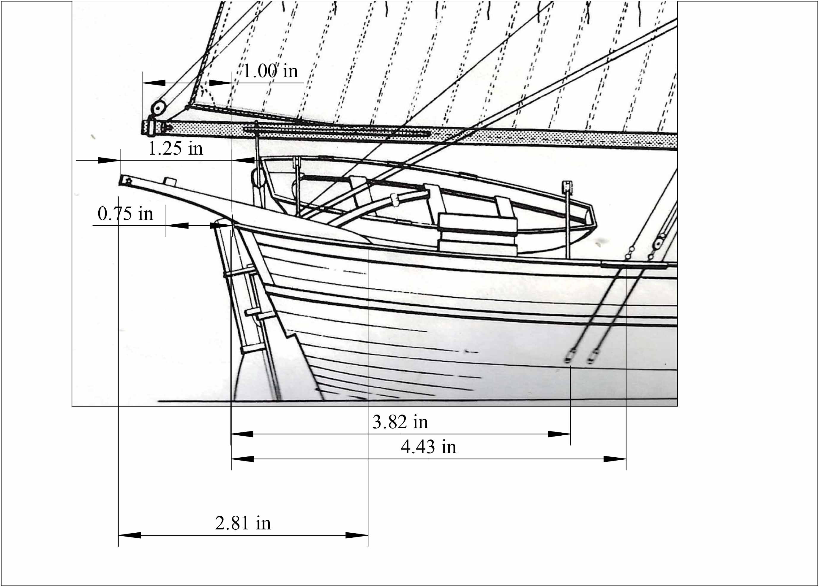
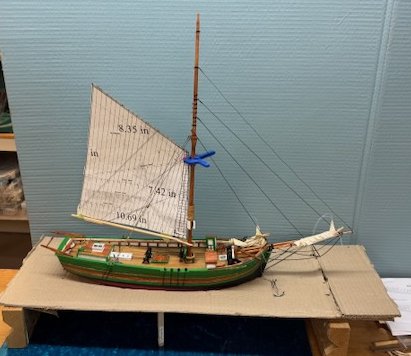
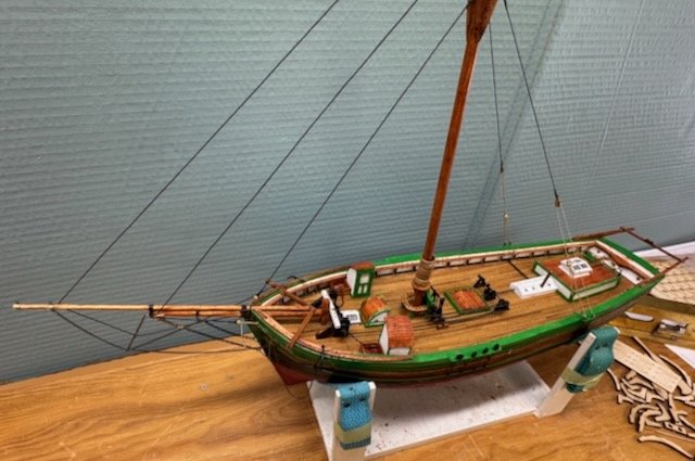
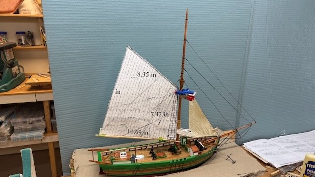
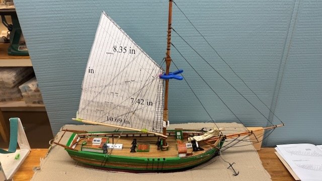
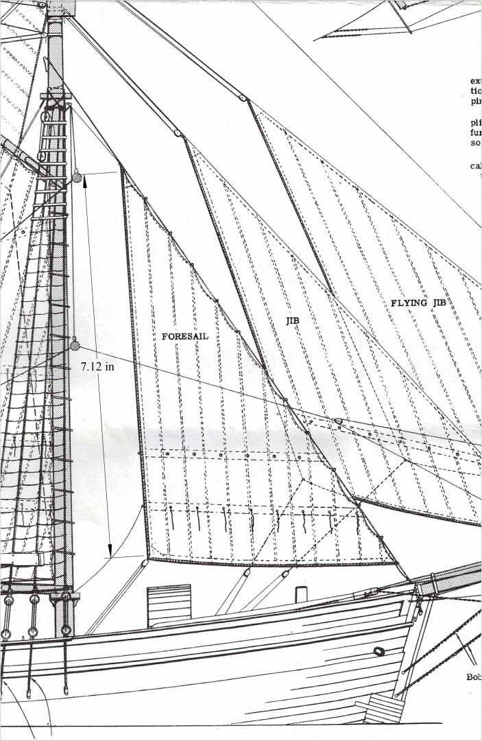
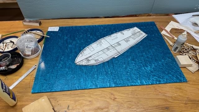
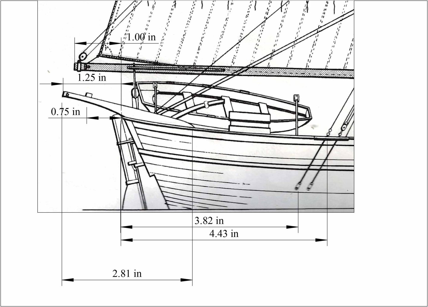
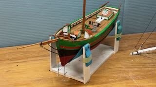
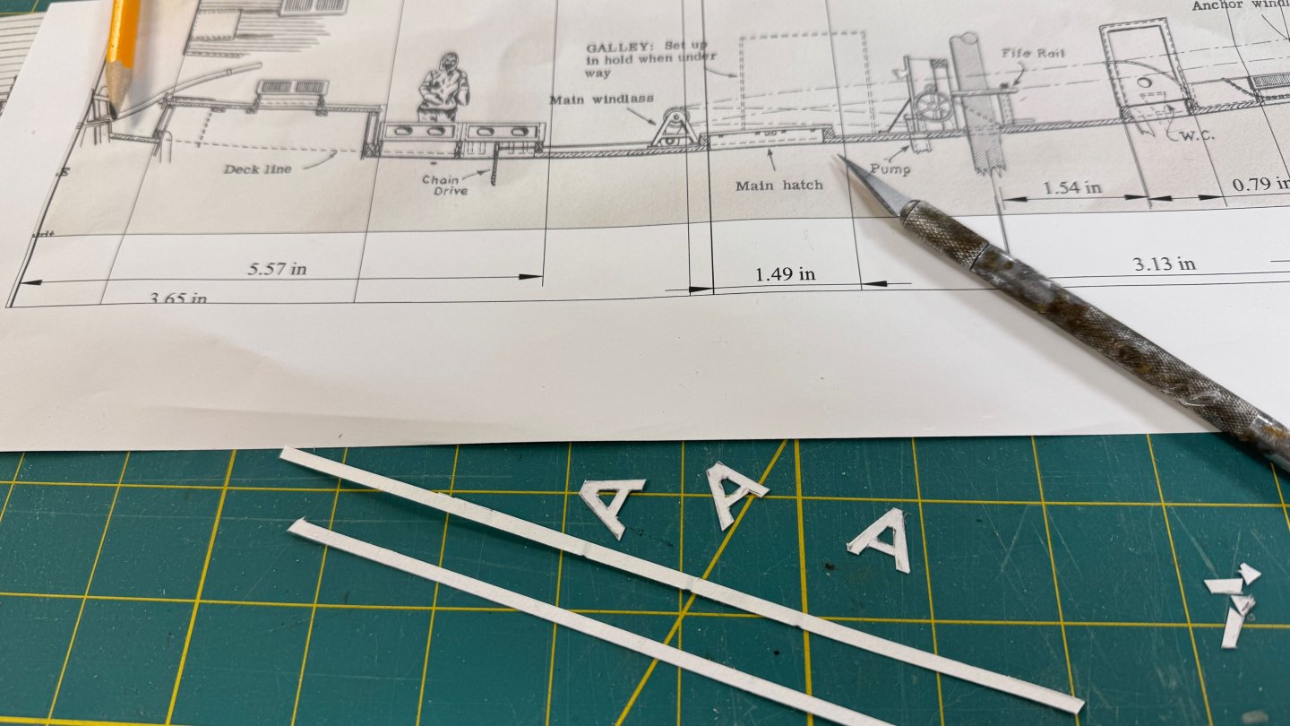
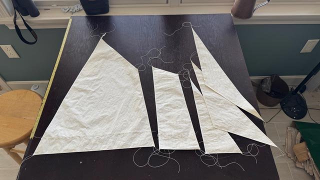
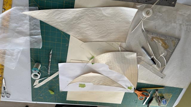
12. transition into show time This is the point where I take pause and try to decide what I want to show when telling the story or in this case stories. I have adjusted my thinking a bit. Last year I told what I will call NW passage part 1 the Brits 1795 to 1850. The highlight of the story was of course the Franklin Expedition for which I built the HMS Terror diorama. I have been studying the Norwegian explorers as I started this build and found the vessel Fram is inside too big a story to be part of this story. I thought I was going to build both together but have changed the order. Also, due to time crunch, I have jumped to building a Viking Knarr, as I will go to Viking settlements next summer. My NW Passage part II will feature this model of Gjoa but include the several expeditions leading through this one up to the MacMillan stories starting 1908 when he joined Robert Peary. There is so much to add I will be fine. As to the NW passage, think about Rasmussen who walked [ sledged] the entire Northwest passage!!! So Gjoa was magnificent in its ability to get through south of King William Island and stay successfully in Gjoa Haven for two years and near Herschel Island a third year. They kept having trouble with their gaff. It apparently broke several times, but all else seemed to work. What a tale… I think now I want to show her with perhaps just the mainsail up, still on her anchor getting ready to leave. [ similar stage I used showing Bowdoin in 1924 after wintering north of Etah, Greenland. .. That said, I need to start the outside work on sails parallel to continuing with the rigging. I am working the rig totally inside out. Most obvious is the shrouds will be later in the build, so I can fit my thick figures inside to make off lines and things first. Before moving on, I want to make a sort plug to encourage other hobbyists to try simple 2D CAD. As only a hobbyist who is often outside my comfort zone, I want to show how simple 2D CAD can assist in things like this project. If one goes to the CAD section of MSW, one finds many people there are very advanced. I am not! One needs not to be advanced to become very happy solving things and saving lots of time. In this update I am planning for sails and the in-water display for the diorama. Let’s see how simple low-tech 2D CAD helps. Sails. Yes, I luckily have the 1950 Model shipway plans. I scanned them and made jpgs. Turbo Cad for windows is inexpensive and does all we need. One needs to watch one or two U-tube videos to get the basics. Let’s see some work 1-3 here is a staging issue. A year ago, I bought 6 sheets of colored acrylic. Two are light and I used one for HMS Terror and save one for Fram. I have two dark and two mid marine color. In the first view I show both colors. In the second view I selected the lighter color as the vessel will be in shallow water. In the last image we show a dilemma that I still working through. The acrylic is 16 by 24. Tip of Bowsprit to current stern in 28 + inches. If I turn the model diagonally it will fit. If I am showing Ice in the water, I can hide the joints. I need to think more about these options. In the end I will have a roughly 10 inch deep by 30-32 inch diarama that will sit on a shelf.....how to stretch the acyliic and not have an ugly joint. 4-6 The first two images show the result of doing TurboCad for the mainsail and the head sails. For the mainsail, which is a hair bigger than 11x17, I add all kinds of dimensions as I will need to lay it out on a large paper sheet and then work with the silk span. For the head sails I just print them out like paper dolls. The third image shows the three head sails, as paper dolls, temporarily in place. I may change my mind later and make them like this image, but currently plan to have them furled. The mainsail paper doll is just a hair cropped but close enough for checking. I will also use it for transferring lines. 7 this image shows one of two hull plans in TurboCAD where I took thick lines and traced the outline of the hull in the half plan view provided in the Model Shipways. I already had scanned, inserted, and scaled that plan for layout of the deck. Now I just add a layer [ watch on U-tube] and use the mirror function to copy the top outline and mirror it below the centerline. I then added a cut line and two circles for alignment. I print it out on two 8.5 x 11 landscape viewports. 8 shows the two halves of the plan aligned and taped to use to plan the cut out. I will cut out on scraps of cardboard to get the right size hole. It will some time before I do the one time only cut of the acrylic. All for now

- 61 replies
-
- 7
-
-
- Northwest passage
- Norway.
- (and 2 more)
-
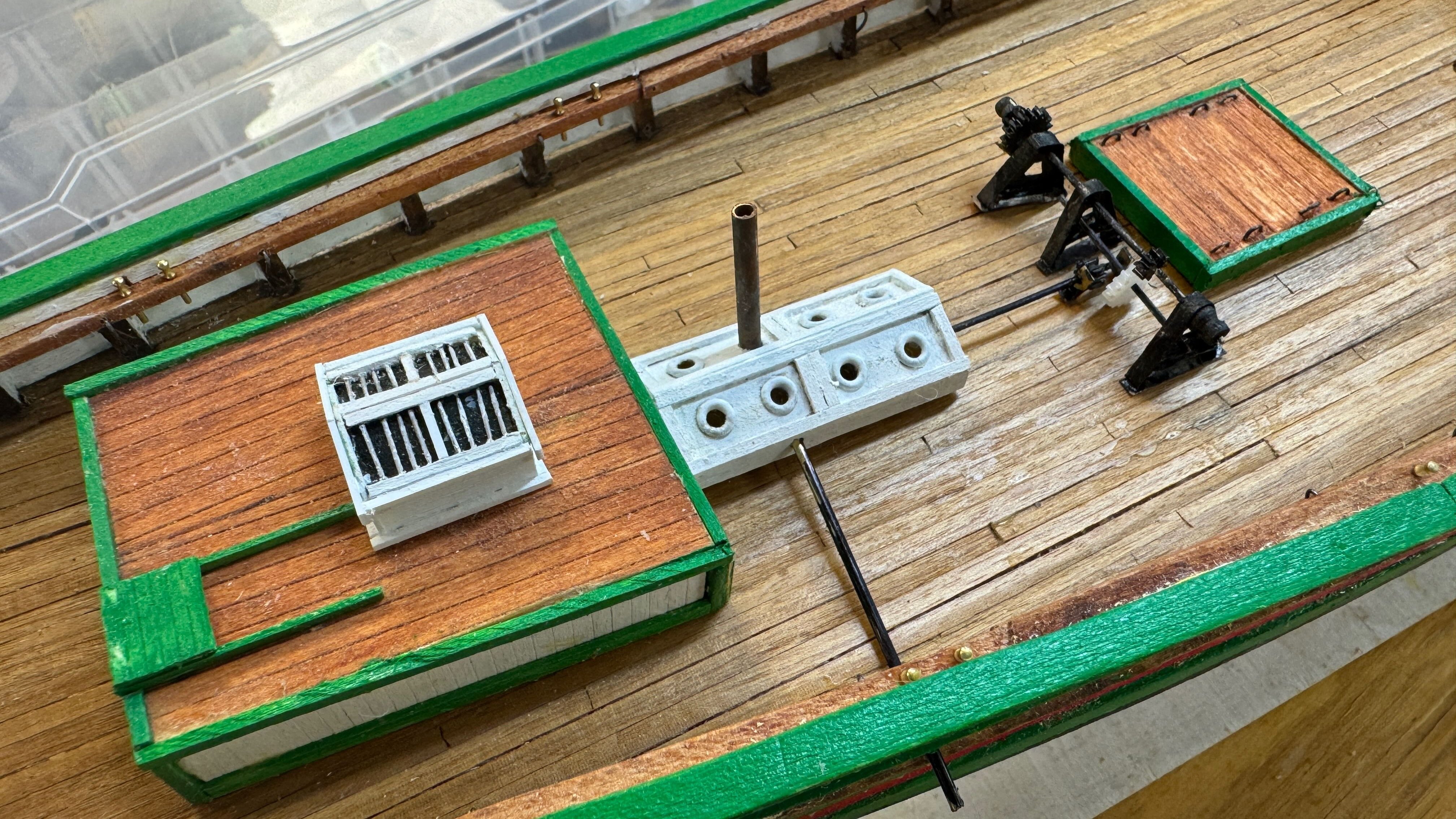
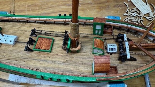
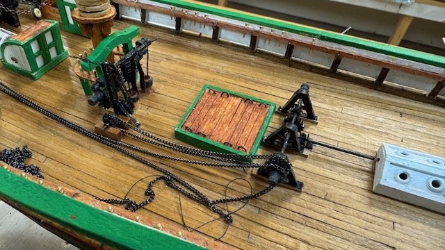
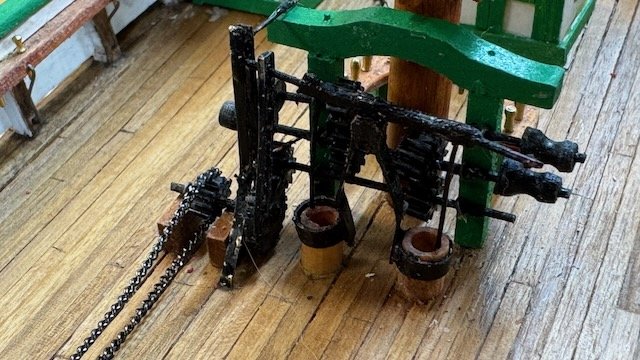
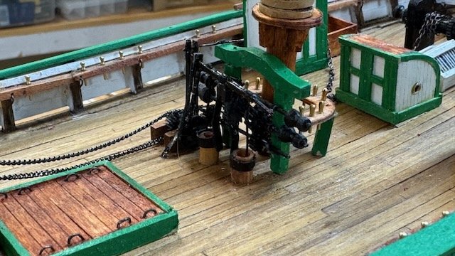
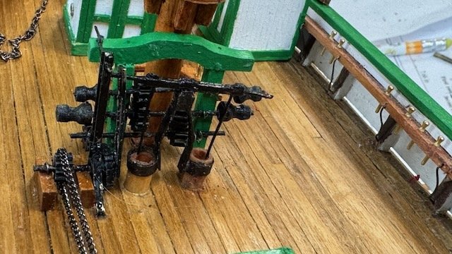
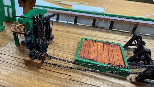
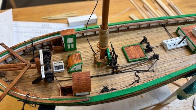
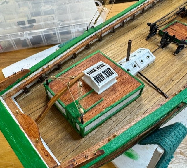
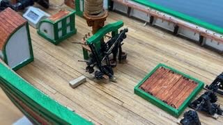
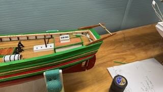
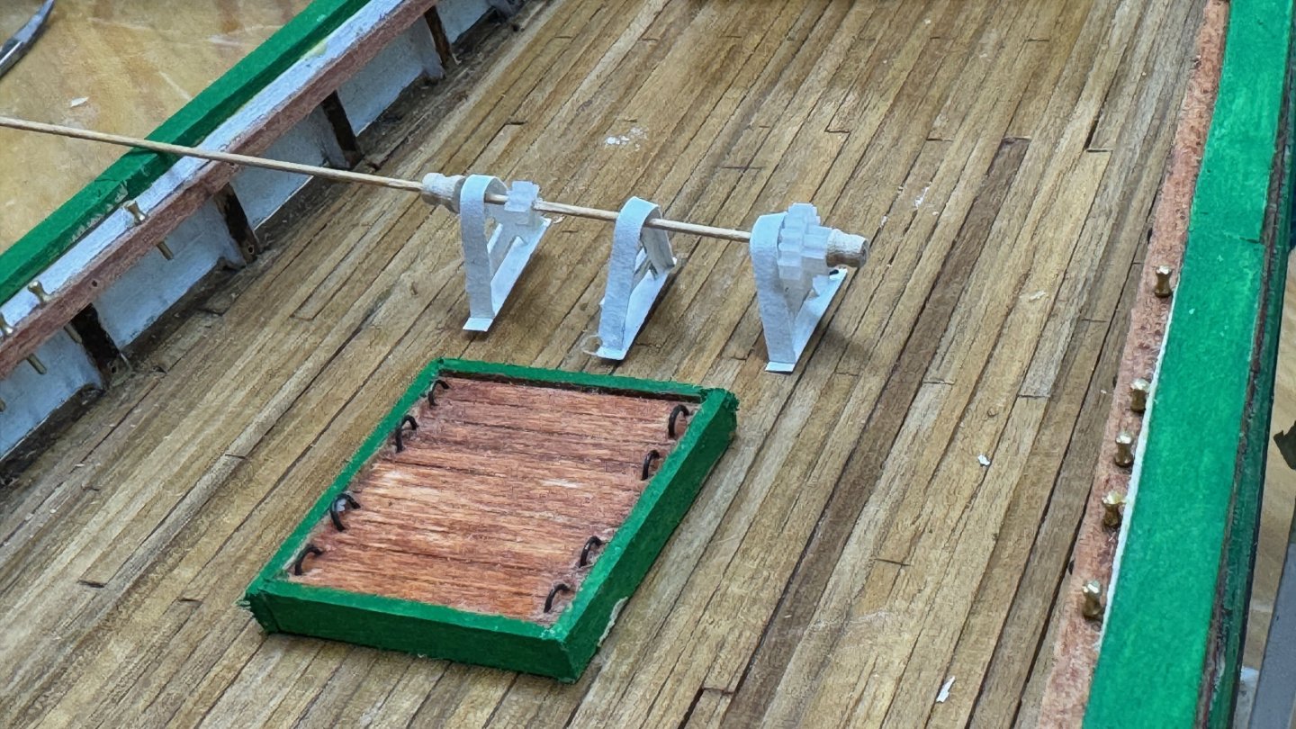
11 deck almost done and rigging no ongoing I decided enough fiddling and completed my central pump gear and combined winch area. I tried to solder the small copper wires to the small brass square tube and went in circles. So, in the end I cheated and used Superglue. I tried using just magic marker, as we know brass and copper don’t like paint, that did not go well, so I eventually gave up and added paint. I call the effect a retiree’s distressed results. 🤫 It is not easy to photo so one can see all the parts. 1-3. these views show chains. The plan shows two chains, one to the pump and the second to the anchor winch. I do not believe they would have sailed so many miles with the chain rigged to the anchor. I may be wrong, but anyway I put it in as I assume my staging will be moored in the north country. 4-6 show three views of the central pump and winch assembly. There is a vertical arm from the big wheel that grabs the pump handle to move it. There is a wire frame outside it with the pump handle protruding though it so the arm is restricted to go only up and down as the bottom goes around the wheel. So far so good…I think I understand it. Now in all the photos, and thank you Harvey who sent me two, where does the chain or a gear engage the lower winch shaft. I had to make that up and just put it on the pump wheel. When I was building Bluenose a few years back and went to Lunenburg, Nova Scotia, I leaned in their museum about the various clutches needed so that one could engage different winches while raising different sails, wanting to raise the anchor, etc. With that logic, one could run the pump only or run the winches without the pump. The clutch would hold the shaft briefly as a gear would be slid sideways to engage, or in reverse to disengage. There was more stuff on a complete set up than in the photos and in my attempt to show it. 7 shows a little more overall and the anchor windlass chain inplace. 8 One more item is thanks to the prework of Harvey and others. I was able to shortcut the progress figuring out the tiller rigging. I had to remake the tiller as the first one just did not fit right. As to its rigging, I was on the right track because my sailboats had a tiller and we would lash it in a similar way when mooring or docking to hold the tiller amidships. Anyway, thanks for the insight I completed mine. 9 finally I scrapped the starboard side and it came out a little better…..Both sides no longer have red paint . I will have photos with the stain in place next time. now we are heading into the rigging. I need to think about how I will stage things. Having read the diaries and chased images I am not sure. I think like me previous Bowdoin diorama I will show the crew about getting ready to sail away from Gjoa Haven. Some ice but water too. I also have to think about getting some crew. cheers

- 61 replies
-
- 7
-
-
-
- Northwest passage
- Norway.
- (and 2 more)
-
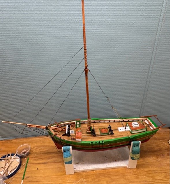
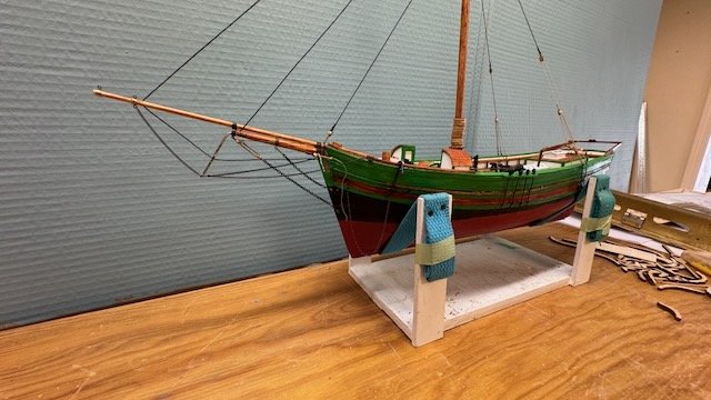
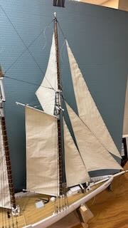
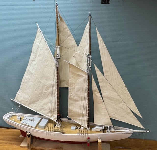
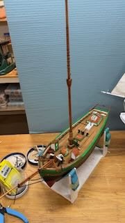
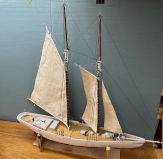
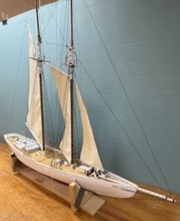
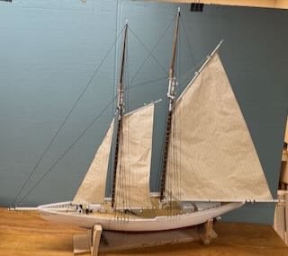
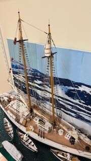
16 b Sails are on Unfortunately time is closing in and I need for a second time to set this fun schooner on a shelf and get on with deadlines. I am going back to Greenland this summer and will be visiting the Viking settlements. To tell that story I am shifting to build of a Knarr. I only have a few months to fit it in ,so off I will go on a new venture….yes outside of my wheel house. On this build I was able to get all the sails on and many of the running lines in place. I offer three views. Since she is 36 inches tall, I don’t have a shelf for her so she is up front on my computer desk, so I will be reminded every time I go there that she is patiently waiting for me. 1-3. sails are all on So off I go to another arctic build and will be back here when I can likely next fall Cheers
-
I love the look of real lights. Thanks for the link to amazon. I think I want to try these on my next build. cheers
-
Harvey you're too kind in your accolades. My soldering is quite low tech. As to the scraping of paint I suggest if you scrape off white it might be easier than my scaping hard paint on soft thin poplar. I won't photo too much of a close up as it does not yet look right.....work in progress ....but I think it was the right thing to do.
- 61 replies
-
- 1
-
-
- Northwest passage
- Norway.
- (and 2 more)
-
Dear Wefalck I agree with your opinion that scraped and oiled is the way to go. Thank you for supporting the decision to scrape off my red paint. I believe your earlier comments suggested disappointment with the museum lighting. It surely tricked me. Also it seems they painted a bunch of stuff white that I did not follow as the older pictures showed more normal " darkness" in winches and the like. anyway thanks for adding you advice cheers
- 61 replies
-
- 1
-
-
- Northwest passage
- Norway.
- (and 2 more)
-
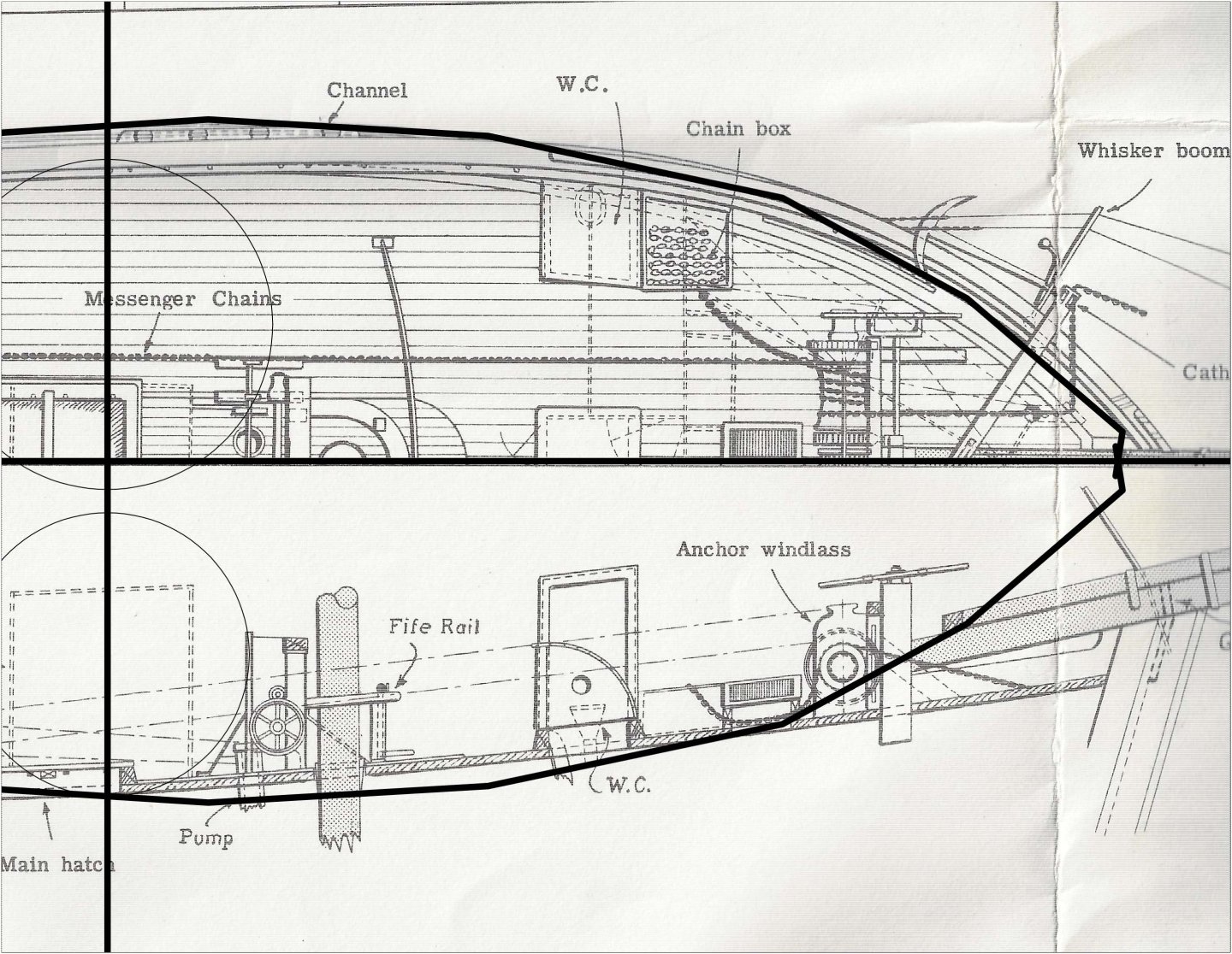
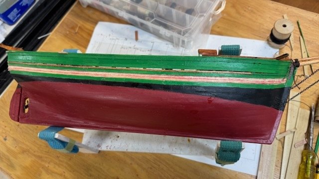
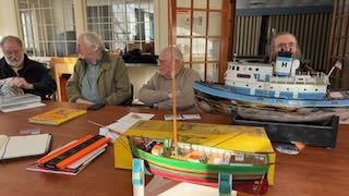
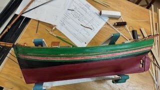
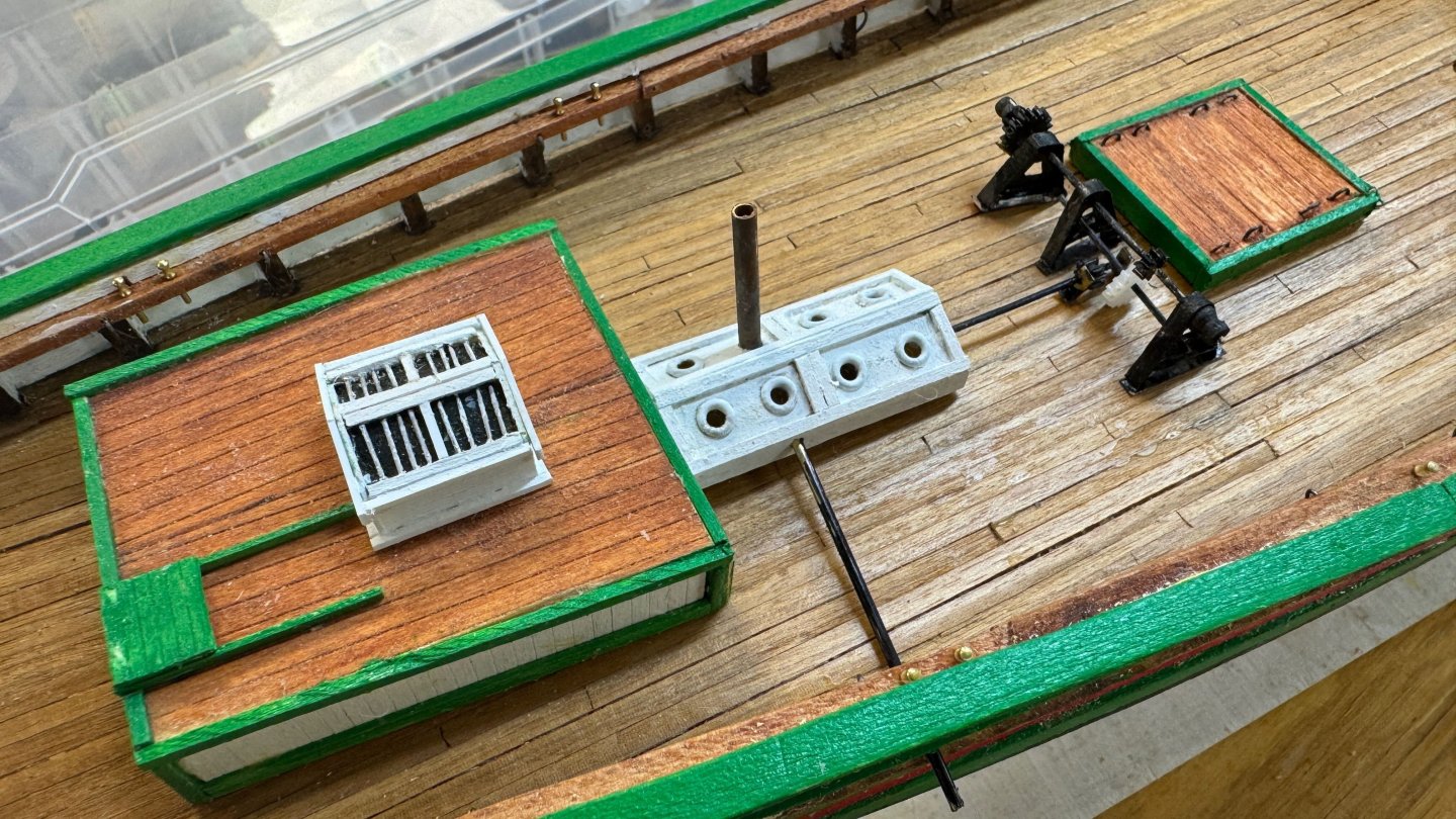
10b more on deck…not done yet There really is a lot to do here on deck, so I better do an update. We also had another critique at the local Modeler’s guild. Pumps and the fife rail/ winches at the main mast: This area is truly a challenge to both understand and then to model. I still don’t think I have it right, but at some point, we need to move on. The photos, thanks to Harvey’s log, of the real deal and added annotations help but they don’t answer it all. I am still working away, so maybe a light bulb will turn on, we’ll see. 1-3 is my low tech soldering to build the pumps and the “fulcrum” 4 5 shows building up of the central winches. The issue I have here is that the three shafts all need to be driven I believe by one chain. Then I assume they have clutches to engage the winches. The pump and winch shafts don’t line up and I see no interconnecting way it all works……more in next post as I sort out what I am doing. Now it is a work in progress. The stern area: 6-7 show the beauty of simple Turbocad. One scans part of a plan and rescales it relatively easily and then either takes dimensions, or prints out the sheet and uses it as a template. For the aft transom davits, I did both, again using a sheet of pear wood for the piece. The mast: 8-9 again the use of Turbo cad and the layout of the spars. Here I added hoops, sliced from rolled tape around a dowel, and the boom seat cut from thin plywood. Next up. a chance for our critique. 10-12. Here I am off to the Downeast Shipmodelers Guild, and we all talk about our challenges. The big subject this month was finding coal to be used on a barge. Real coal from the famous Maine tugboat Seguin was brought to the meeting…kind of cool coal. I asked the group to help me solve a problem. I had studied paint colors and wrote about them in early posts. I had come the conclusion that the thin strakes were painted red. I have since changed my mind. I believe they were oiled and in the museum photos, the lighting seemed to make them red. Worse, the paint I had used, called Fiesta Red, is called artist enamel that can even be baked in the oven…wow. It is hard. So after dialogue with several suggestions, some type of stain wash was the consensus. In11-12 I scaped as well as I dared and then sanded with a cut down emery board. I then did the first coat of stain and well I feel better even if it is not right yet.

- 61 replies
-
- 6
-
-
- Northwest passage
- Norway.
- (and 2 more)
-
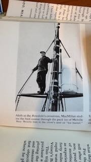
My bad....I should have written" Ice Barrel". not bucket. Here is a picture from the biography of Donald MacMillan who went with Peary to the North pole and then led his own expeditions from 1910 to 1954. He designed and built the Schooner Bowdoin right here in our town , so I am quite prejudiced. Bob Bartlett was with him too with Peary and again sailing Ernestina Morrissey. Their name for the barrel is what I latched onto a few years back. Here is a photo from his book with the caption. More important is to understand the ease of entry. All the peak halyard blocks and lines are behind the mast making it easy to both hold on and climb in over the top. getting to the spreader is no big deal. Perhaps when I get there I will find the same logic. I don't argue the idea of a trap door, it just doesn't seem safe. Think of the thick gloves/mittens and bulky clothes being worn while climbing or worse descending. what is there inside to stand on while the hatch is open? etc. I am totally guessing at this point but would image the Jacob ladder SHOULD have gone to the top....😁. I'll wait till I get to the halyard rigging. I probably just leave it a mystery. cheers
- 61 replies
-
- 2
-
-
- Northwest passage
- Norway.
- (and 2 more)
-
Harvey I can not even begin to join in knowledgeably with the recent exchanges here about the Kayaks, sleds and small boats . They are wonderful to look at and also to imagine about using. I have read a huge volume on the arctic and remain keen on learning. Your build is terrific for that purpose. Also I have been looking over your rigging with equal awe. Your larger scale is helpful for one's thumbs, but the workmanship is definitely up to the task of more detail. Example. drawing the seams on the sails you made the two distinct lines that are great to see. Working ar 1:75 or 1:64 and even 1:48 I have never succeeded with two lines. Another detail is your cringels; I find them to be is awesome. I recently got the book you recommended on the rigging and I have to agree that the drawings are extremely helpful. anyway I just want to thank you again fro sharing your work. jon.
-
16a. another two sails….sort of Thanks to those visitors and their likes. The shipyard seems busy, but the progress seems slow. We forget how many different lines, their spices, their blocks an anchor points etc. for each sail. This partial update is to record the end of the year, with three sails in place. Their lines however are not. We have three views from different directions showing the sails. • The main needs the most work; the topping lift on the starboard, lazy jacks port and starboard, gaff down haul also starboard and perhaps a flag halyard though not a raised flag during a race. • The foresail need replacement throat blocks, and both a topping lift and gaff down haul. I need to do a survey and make up a kist of blocks so I can get them from Bluejacket and have them all match. • The Jumbo needs sheet and temporary preventer, sail downhaul. Also, not all hanks are in place I have also a view on all the reef lines being hung with wet white glue to they hopeful will hang down and not just stick out. Some are very stubborn. If one looks closely one finds several items still missing on deck. I need to get the fife rails , representation for the pumps etc before closing in. As some wiser builders than I have said...start in the middle and work out 😄. I will not start the ratlines until all the inside lines are made off. We all learn the hard way that one never seems to have enough pins for tying off all those lines, we must also add dory tackle and hooks, set up snatch blocks so the forward winch can raise and lower sails. Fortunately I only need one dory..... I hope this new year offers the chance to get most of this work done. I have a third build [ Fram] that I need to start shortly and this one may again have to be delayed. I am giving myself only a few weeks more and I know that is not enough time to do it all. Fortunately this one does not go anywhere for another year and with the sails on she looks OK. My goal is to hang all the sails and be basically done with deck furnishing. We'll see how we go. cheers
-
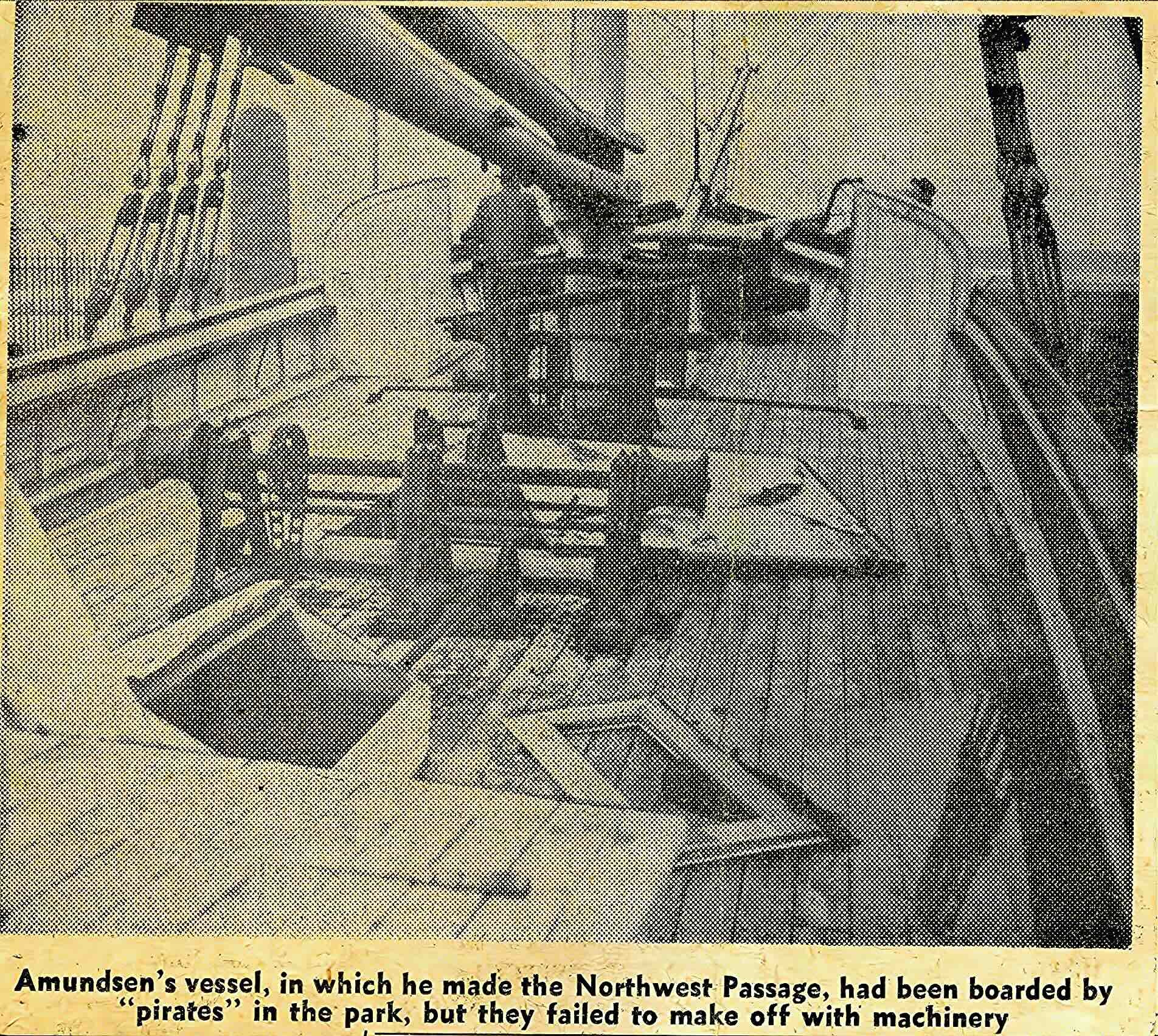
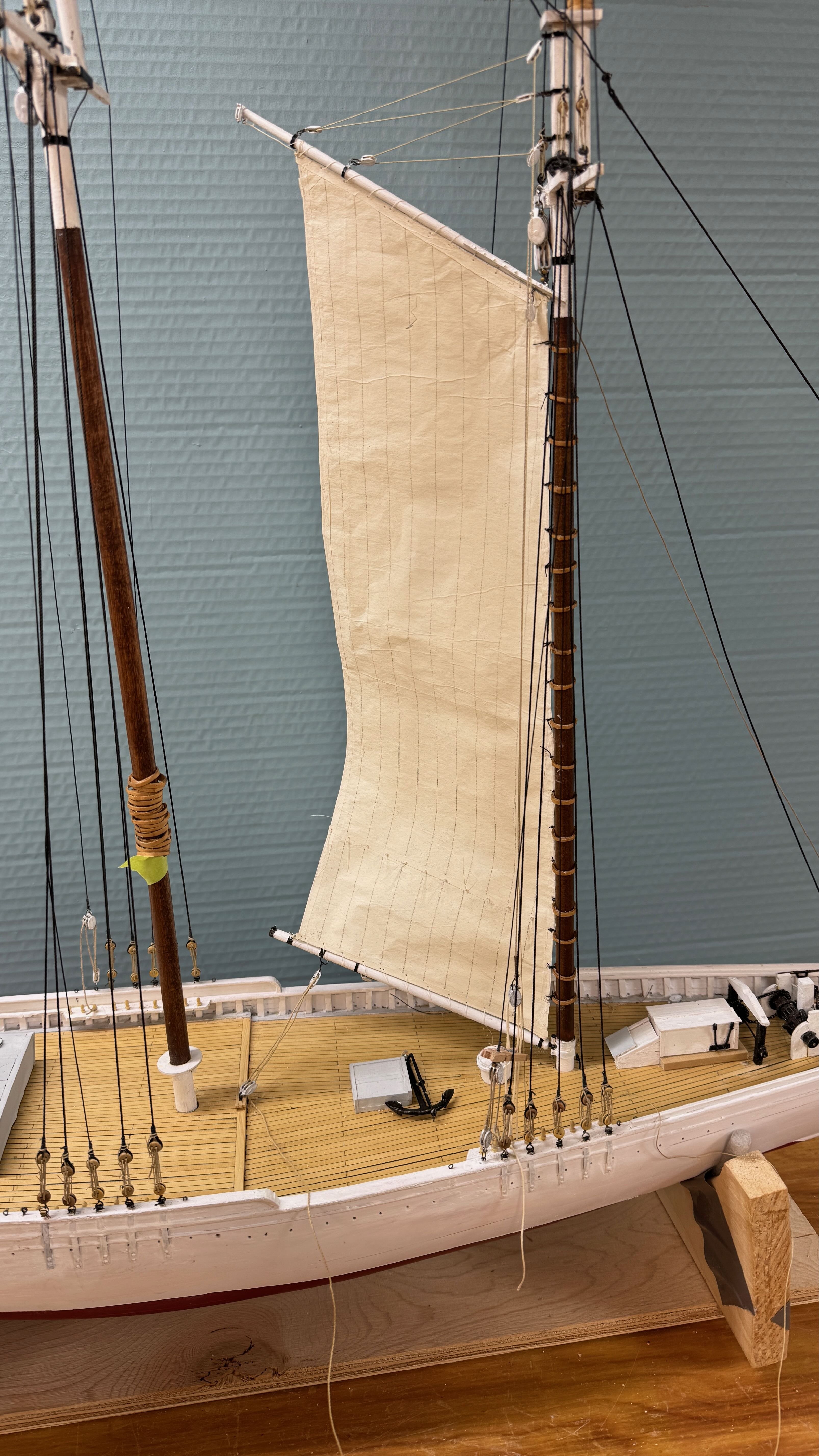
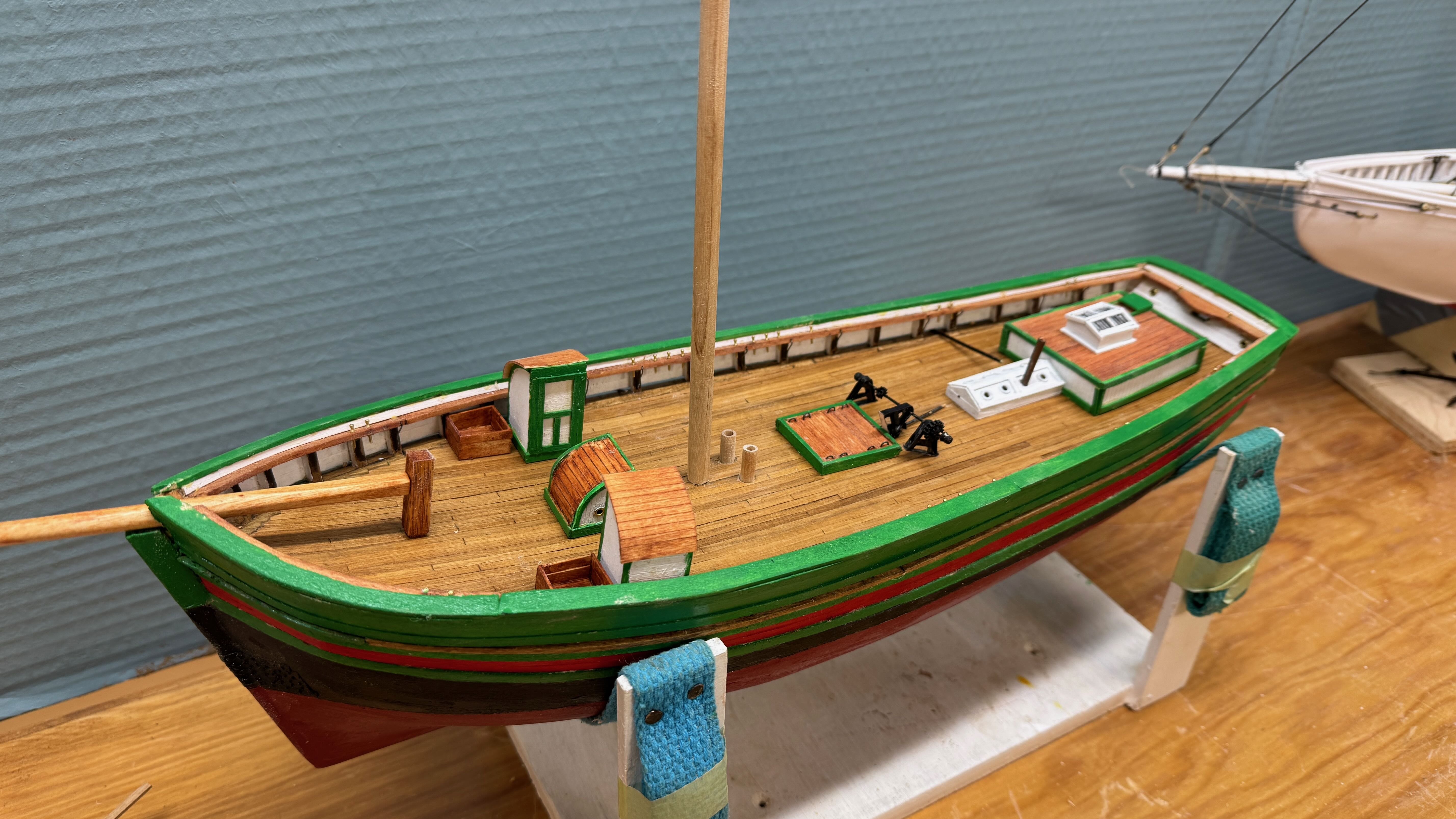
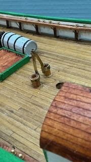
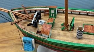
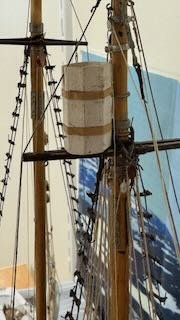
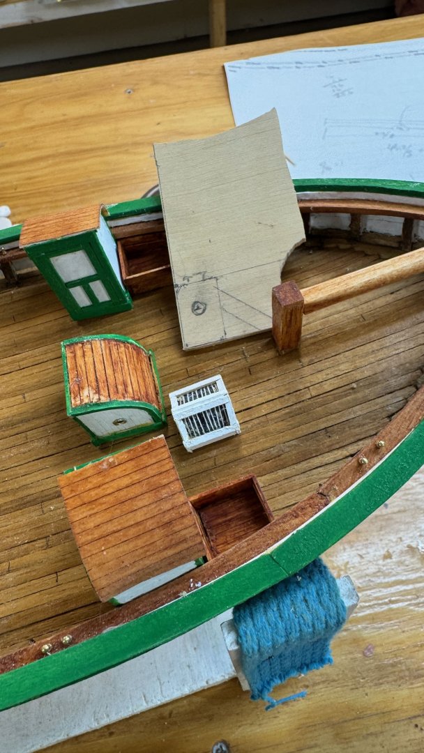
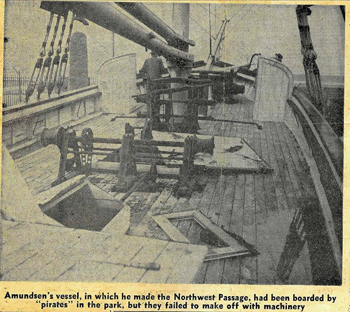
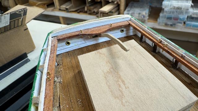
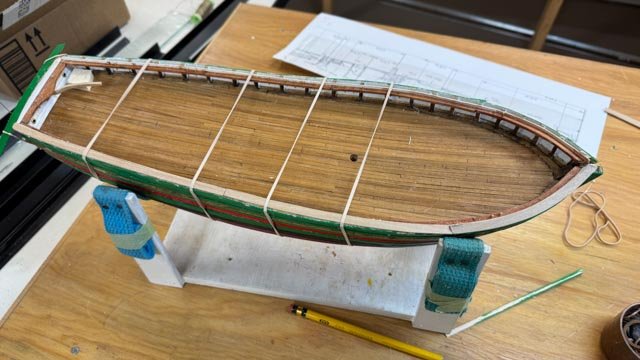
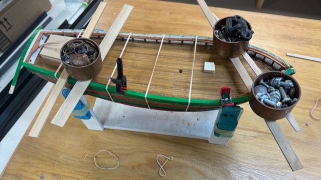
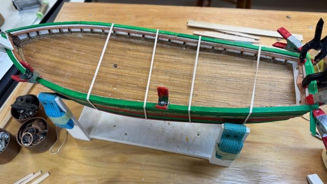
10a part way through the deck furnishing Before sharing progress. I want to share a news clipping I received just recently. A local retired Shipwright passed away and donated his library to the local library book shop. The volunteer there helps us at the historical society, She knows I am doing a multiyear study of our shipyards as well as the study of the Northwest passage and other related stories. She showed me this clipping knowing it would fascinate me and here we are. 00 The online record states that the San Francisco park had suspended the repairs to Gjoa in 1939 but resumed them after the war, and completed the effort in 1949. The clipping here is from 1957 and has a great photo of the deck. This image agrees with a one other [ I posted it earlier] and I have followed it. The forward anchor windless assembly is black and the mid or Main windless is dark here, and green in a museum image. So along with the enjoyment of hearing about unsuccessful engine pirates, we gain a tid bit of info to either use or not I understand today much more of what is on board seems to be white. There are not however comprehensive images I have found and for a few issues, I hope to be more successful. Specially how did they rig the tillar? The working progress including a snowy New Years This partial update is to cover some of the fiddling to get the deck furniture done. When scratch building, we get to rummage through our stash of unused stuff. Either unused kit material or surplus buying that now fills many plastic tubs. We also get to build stuff, and it can be a real learning curve. A. First up the anchor windless. 1 -2 here I have taken an unused kit supplied windless that will need to be extended both for winches and gears for the drive chains. In view 2 I drilled holes for short extension shafts. 3-4. here I am used sheet pear wood to make up the windless stands. 5 and here we are finally set in place. I do openly admit the diameter of the barrels is a bit undersized, sorry…… Ice Barrel....[ crows nest] I have a question that I plan to ask Harvey….if the ice barrel is suspended as it is shown on the drawings all by itself. I assume hung on some of those many mast rings. However, I ask……, with no extended climbing means, how did the crew get there if the wind and sea are a mess? 6-7 show two images of the ice barrel on the schooner Bowdoin. It sits on a spreader, and the ratline takes you right there. Just a comparison and the basis of my rhetorical question. 8-9 to build the barrel, [ it has sloped sides] I took the inside lines from the plan and shaped a plug. I then covered it with saran wrap and over a few days glued piece after piece. I then sliced off the bottom of the plug and glued it in for the floor. 10-11. here is an overall view showing the anchors and some progress on the bowsprit. The second view shows the anchor winch with chain leading to the boxes and ice bucket sitting on the deck waiting for me to figure out how to attach it to the mast. The main winch pieces are waiting to be assembled with the pumps too. Cheers


- 61 replies
-
- 9
-
-
-
- Northwest passage
- Norway.
- (and 2 more)
-
Thank you Keith for your greeting and I offer them to you as well. My daughter made up the remaining sails while here, so now I need to get them on. A little wiggling is needed for the jumbo, but hopefully all the others should be OK. There are so many other things happening , the productivity in the shipyard is a bit low. I did set the main, but all those lines that need to be made up are still in production. I hope to get it done and a posting before the new year. I am running low on parts too, and may need to add to my crew. cheers and Happy Holidays
-
John I can not wait to see the real thing again with those stairs. Just amazing. I also want to learn more about the battery and tiny lights you have shown a few times, I am thinking about that photo you took here but later with the roof on with inside light coming down the stairs.....it will be fun to see. Merry Christmas
-
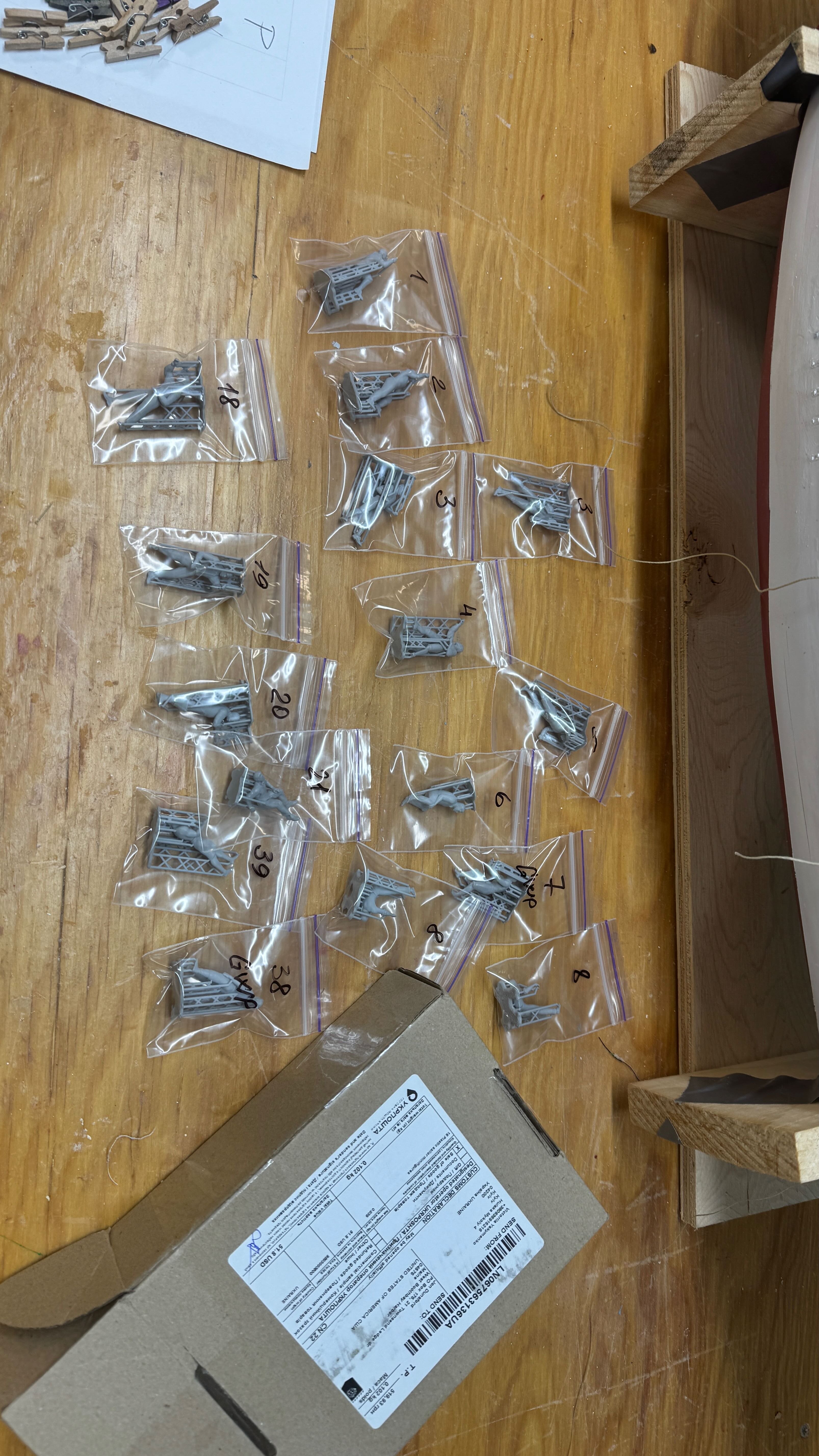
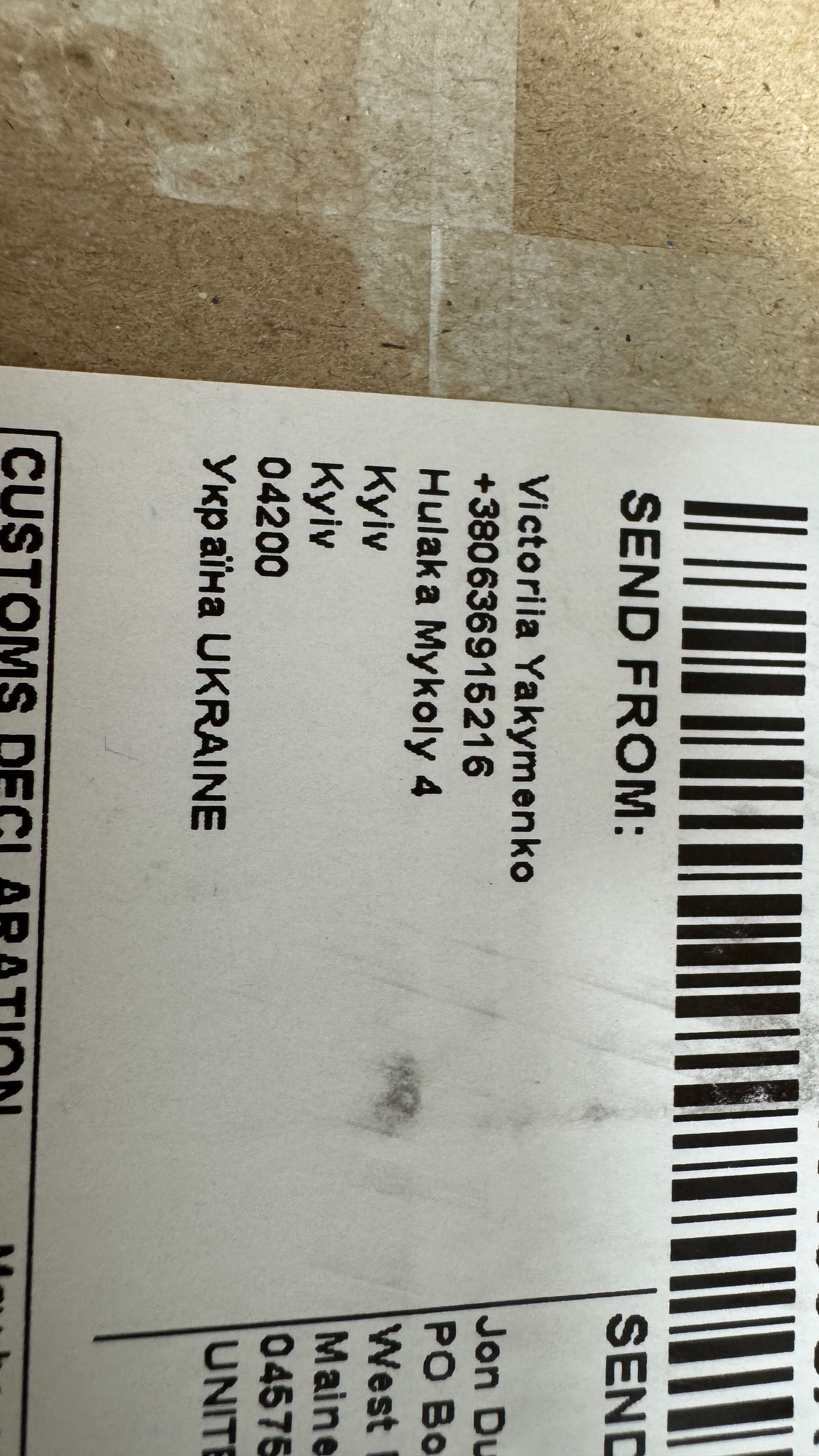
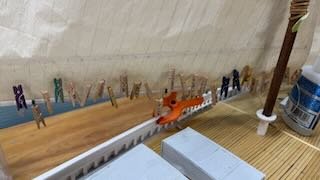
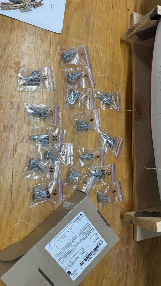
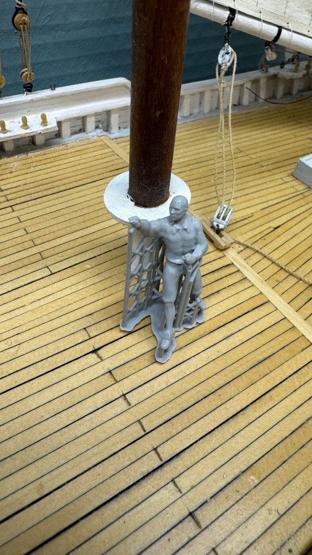
Thank you Phil and others for your likes. 16a Just a quick update as we get to the Christmas Holiday. Also it is snowing and we are in a perfect White Christmas on the Maine coast this year Another milestone was reached as the first sail is now on. But more important was the show up of the main crew. 1 here we see the foresail bent and sheeted. I usually engage the boom tackle, so the sail stays in position. In this case we will have starboard tack. One note is my stash of blocks. I try to use Bluejacket blocs on my Maine Schooners, and I am running short of some sizes. The example here is the throat halyards. When I get further along and know what I need, I will order and reinstall those two smaller blocks. That effort will raise the throat just enough to straighten out the luff, and all will be in order. 2-4. The main crew arrived. The first view is the whole crew; 16 figures in the box. They offer many different poses, so I ticked off this bunch and hit buy...simple. I ordered them from Etsy and in the second photo, look at the shipping label…wow they came from Ukraine! I am pleased to support them in this way, as tiny as it is. The third view is one figure as they come. The detail is incredible. In a race they had maybe 24 on board. Many wore street cloths, smoked cigars etc. Maybe as I go back online looking for Norwegians for my Gjoa build, I’ll find a few more. Merry Christmas


-
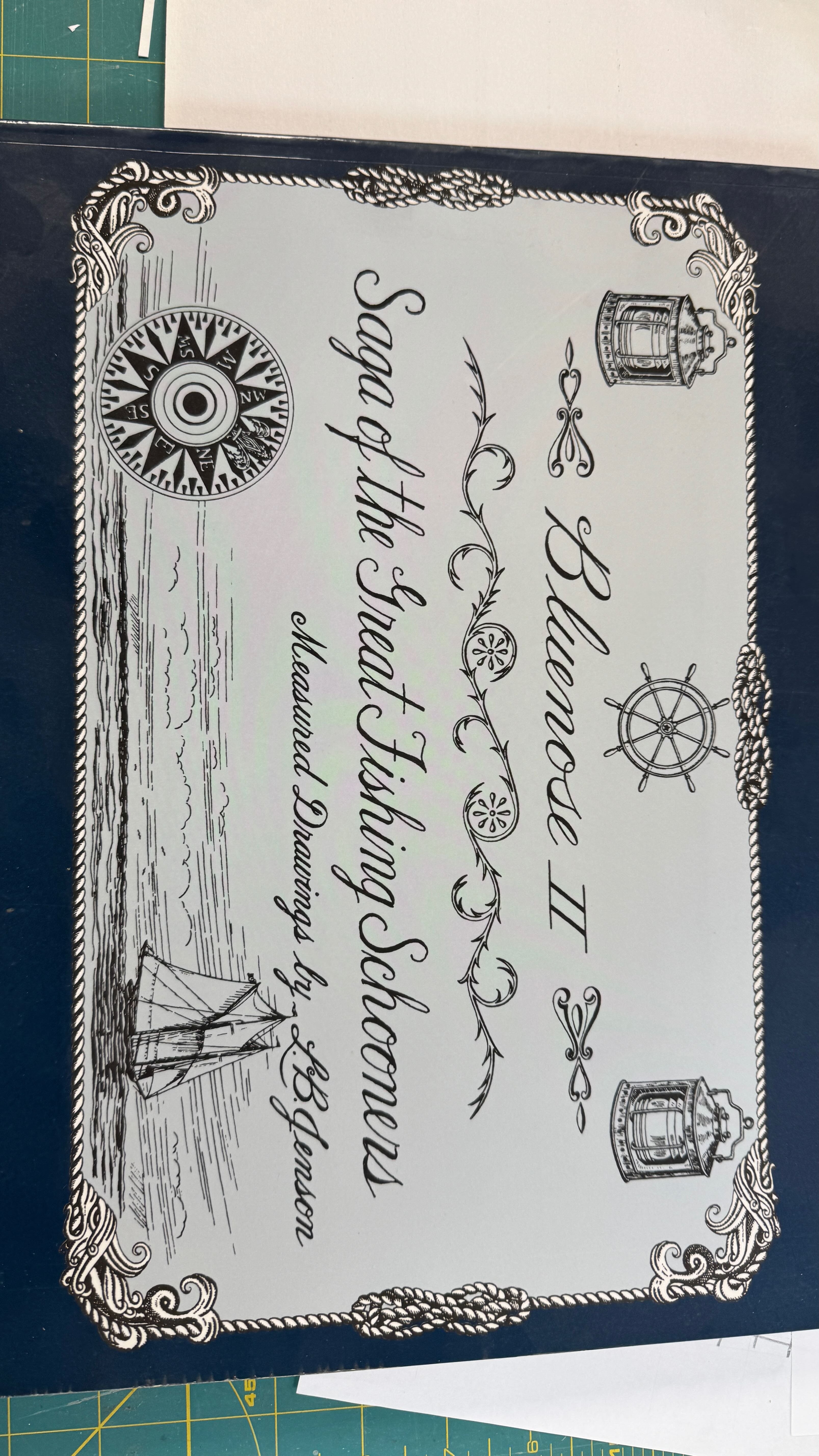
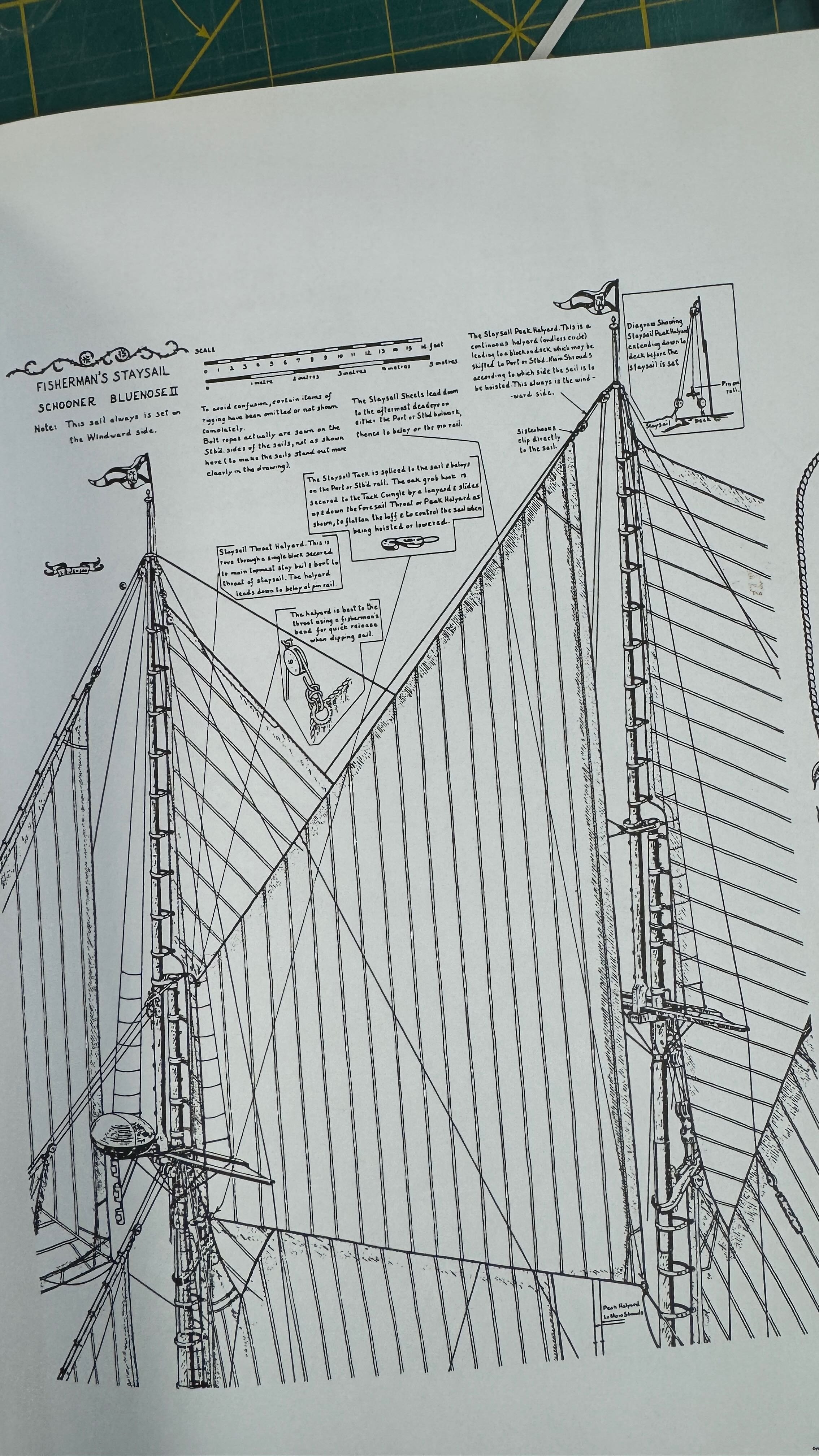
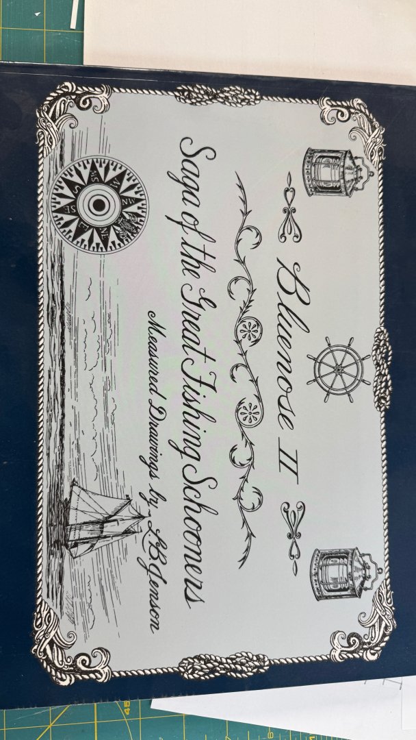
Phil Nearly 10 years ago I made my second visit to Lunenberg to sail on Bluenose II. The day before our sail, they were rained out and I got to spend a good hour or more on deck with the crew taking a million photos and asking lots of questions. I also bought a copy of the book sharing all the detail of her design. On one of the pages [copy below] there is a description of rigging that sail, the four corners do the following • Peak halyard is continuous line that goes through a snatch block either port or starboard rail depending on the tack • Throat halyard goes to pin rail • The sheet leads down to aftermost dead eye…..I believe that means another deck snatch block to make it easier to handle, and again it would be either rail based on tack • The tack is the most interesting and not possible to model. There is a hook that is lashed to the tack and secured to either of the foresail halyards. It is meant to slide up or down the foresail halyard and thus to flatten the staysail at mid point. The tack itself is belayed at the outer rails, again port or starboard. In my studies I have found many similarities between The Bluenose information and new England Gloucester fishing schooners. There are a few differences as well. I will likely follow this wonderful detail as we all know outside of the Howard Chappell Fishing schooner book, there is little other information. If there is more out there, I would love to read it even it comes too late for my work. Thanks for pointing our this issue. Merry Christmas too Jon

-
thank you Druxey. I have used similar setups making masts with Sitka spruce up to almost 3 feet. However masts or other spars over about 15 inches only come up from time to time and I somehow get through the challenge. A more worrisome issue is the Norwegian rigging come straight at me.....Thanks to Harvey I just got a rigging book written by a Swede that looks like a whole new rabbit hole to descend. We'll see how that goes. cheers
- 61 replies
-
- 1
-
-
- Northwest passage
- Norway.
- (and 2 more)
-
Dear Cathead My father in law was a navy officer below decks running the boat [ Destroyer] during WWII. After he came home he spent several years working in Schenectady, NY where they build Railroad engines and this anvil ended up in his shop. I don't know its history other than it was one of his favorite possessions. I am sure it has a hidden story that would be fun to know. cheers
- 61 replies
-
- 2
-
-
- Northwest passage
- Norway.
- (and 2 more)
-
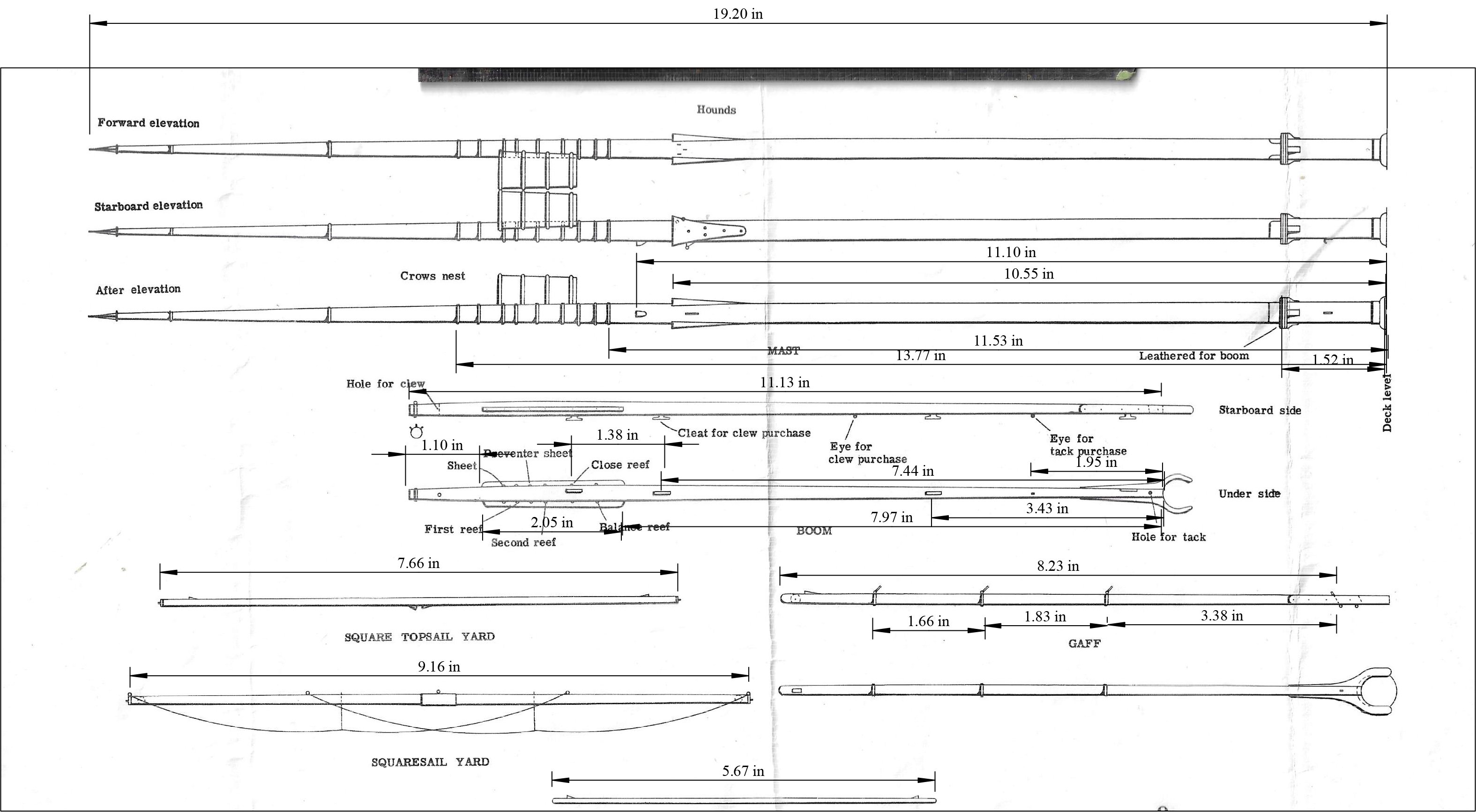
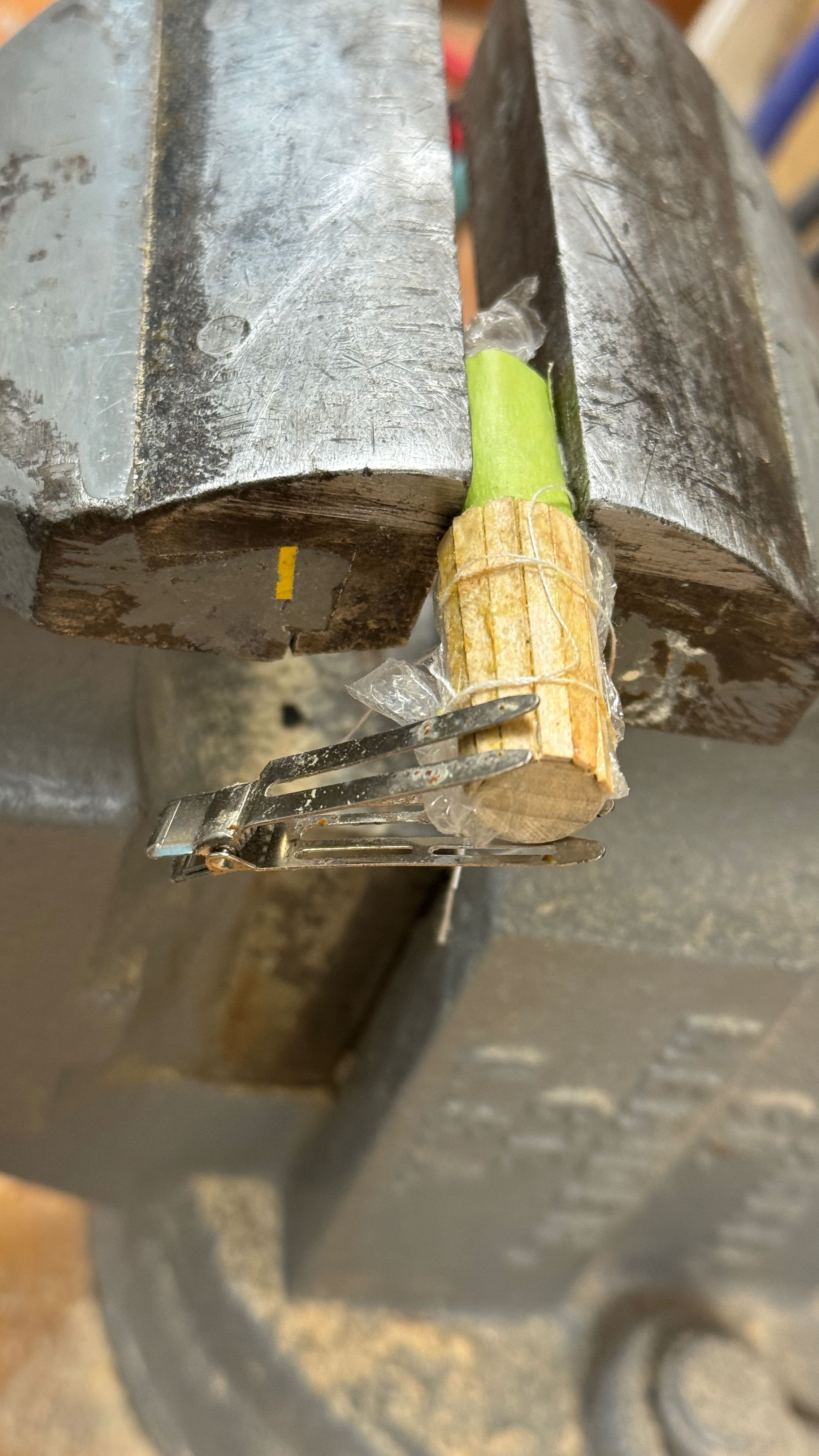
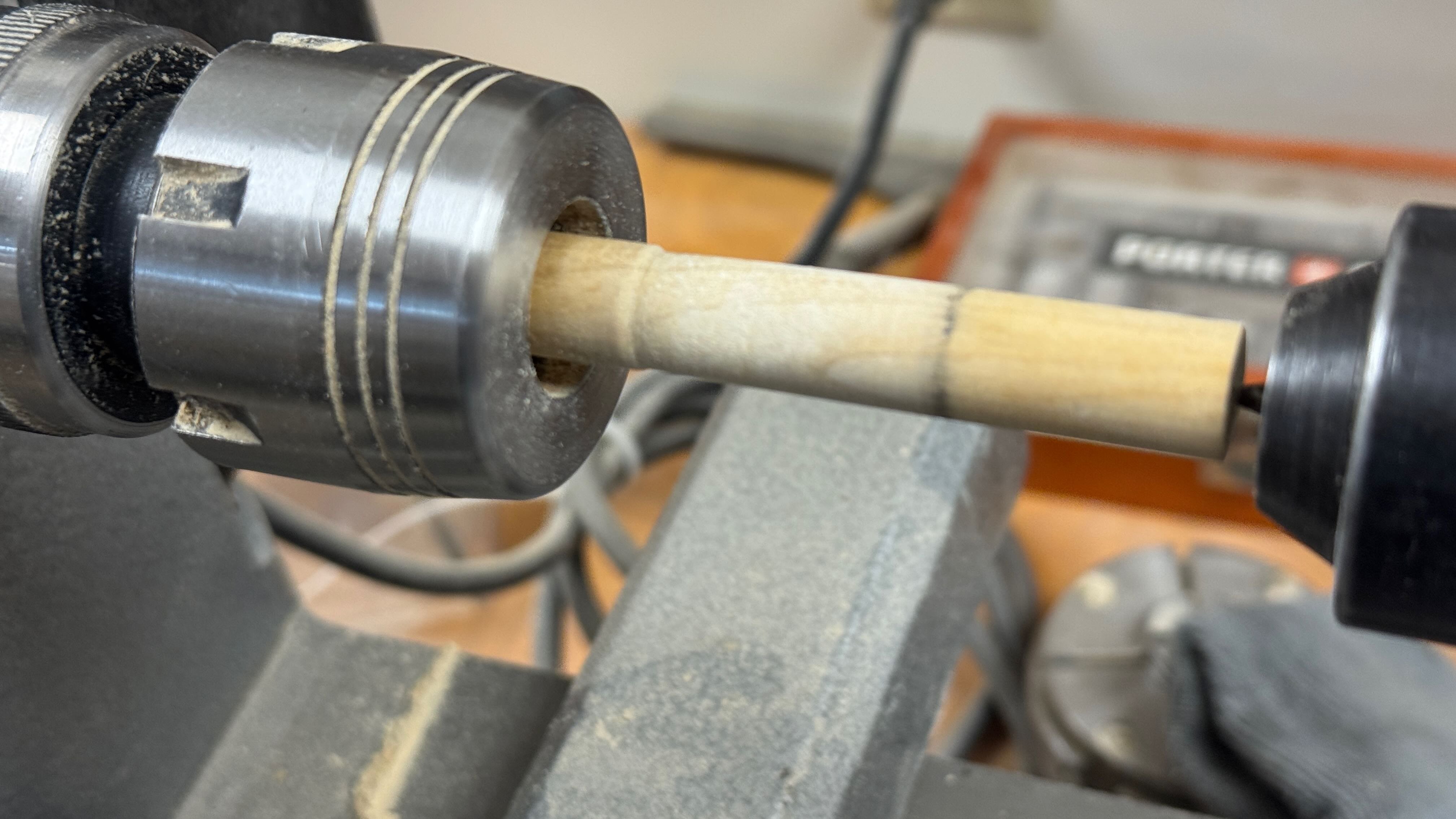
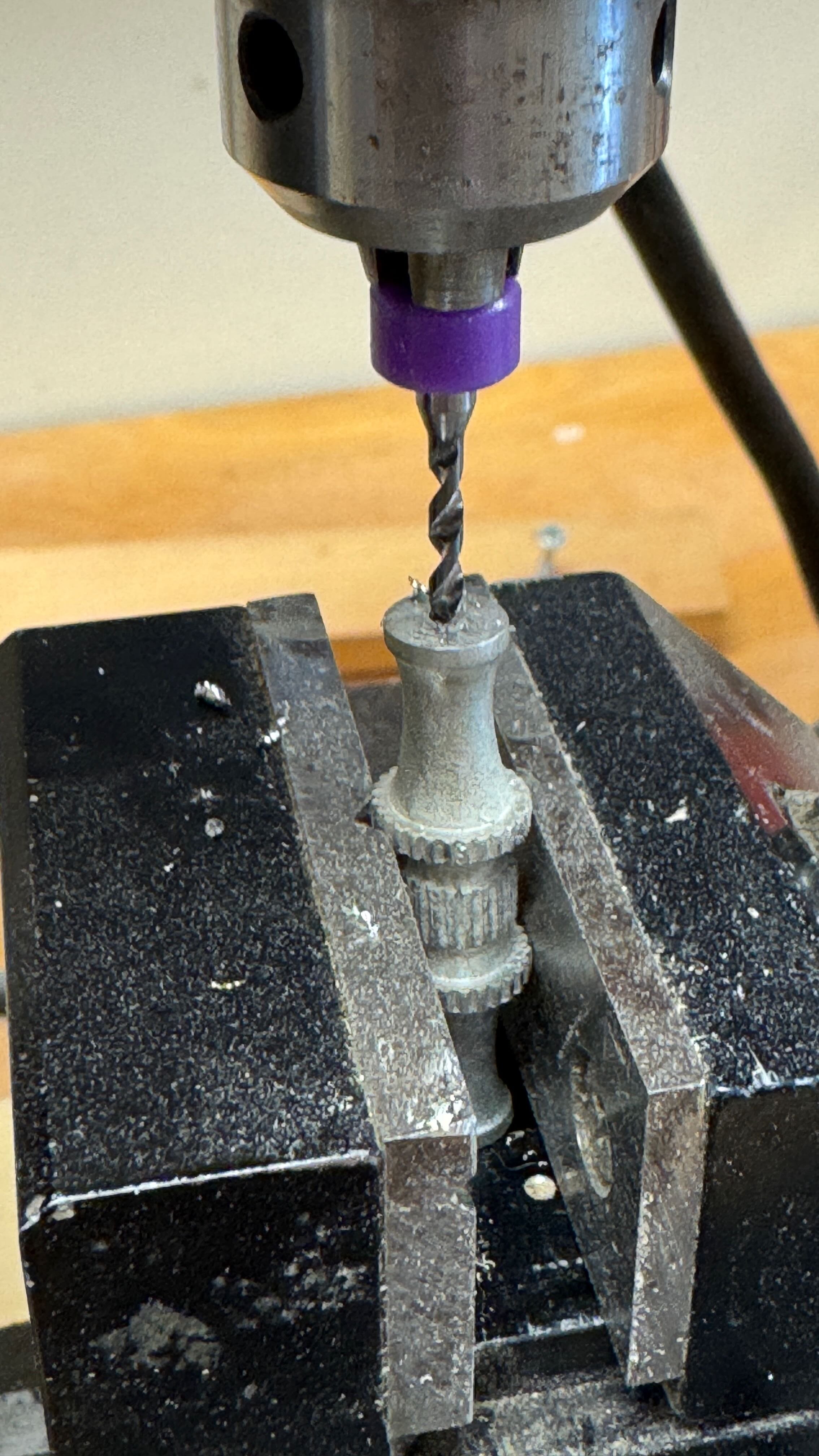
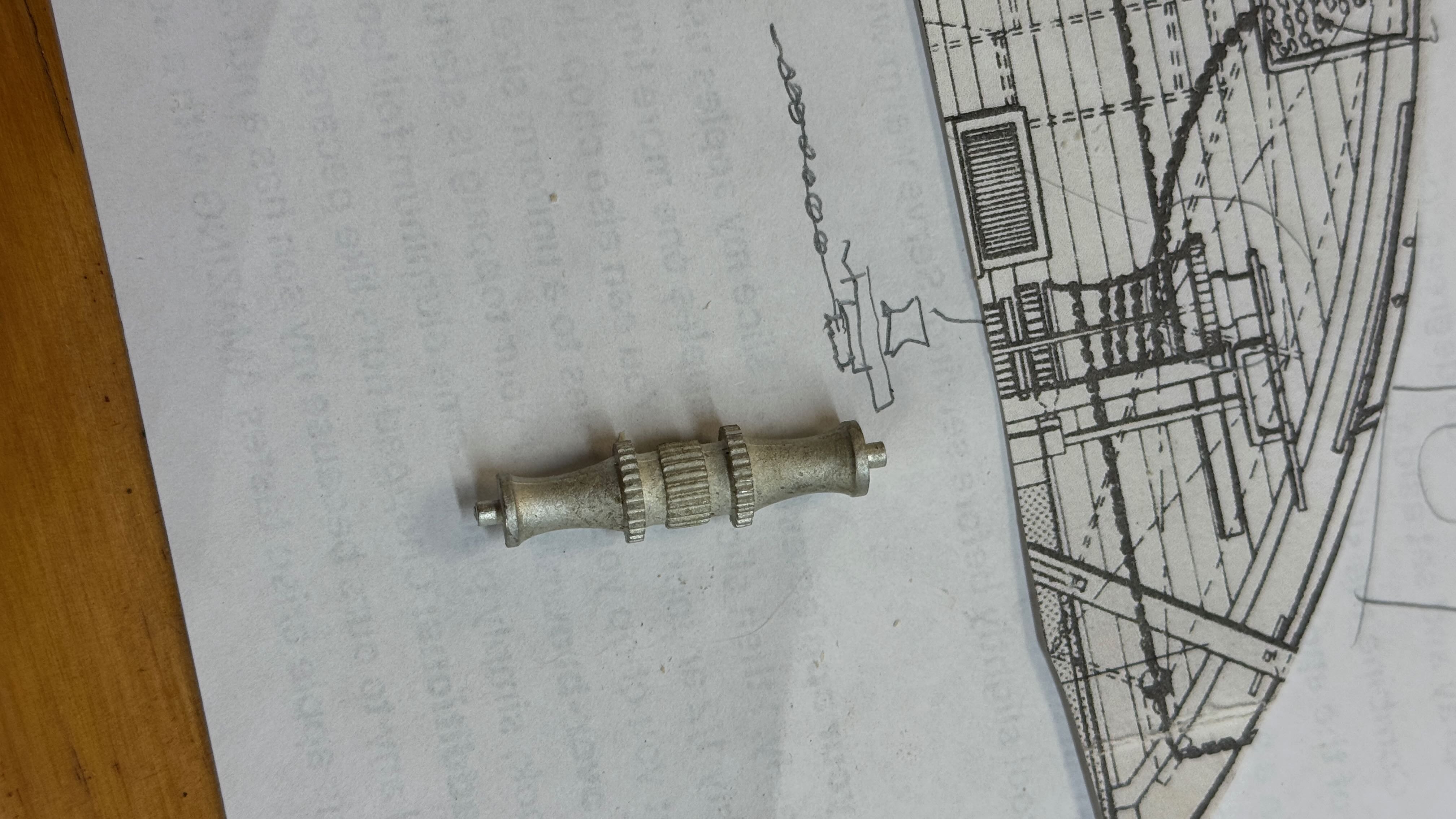
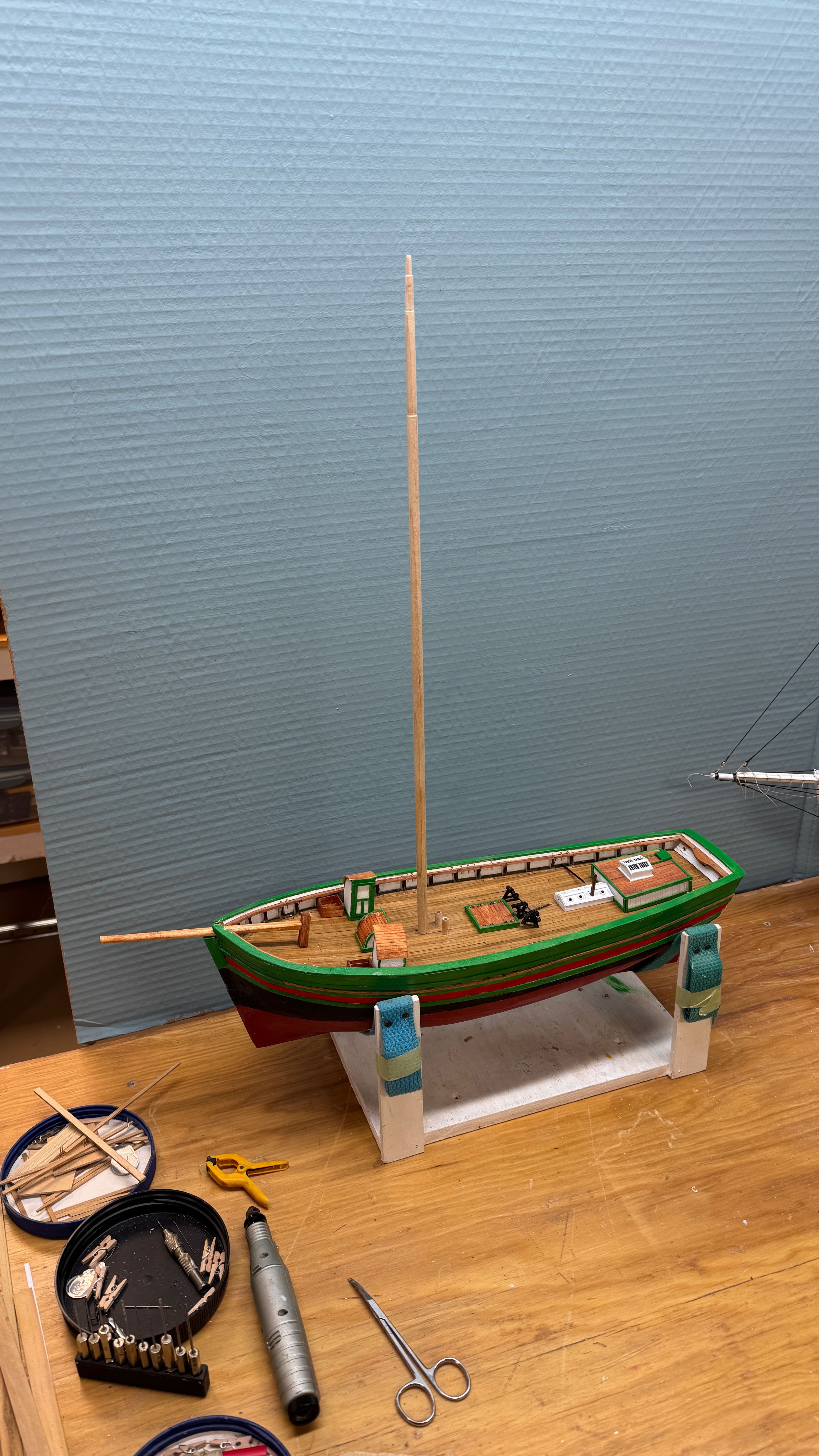
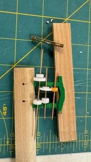
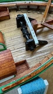
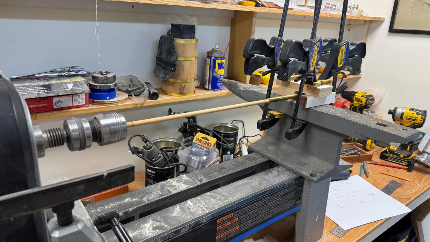
9 working on the deck furniture. I am working away through the deck furnishings. 1. I counted ten main deck stationary items including the skylights, and here 8 of them are almost ready to glue down. 2 ,3,4. these three views show my experimental approach to make then main windless out of paper, a tiny wood dowel and plastic gears sanded down to size. The two deck brackets holding the shaft coming forward from the engine room. I switched to brass. 5 I am using the old thread trick to try to simulate iron rods for the forward skylight. I used pins on the aft cabin skylight. We’ll see if It works here. 6 here I have blackened the windless parts. the paint helps the paper become more solid looking. I found that black magic marker is better than paint however on both the paper [ second coating] and dowels. It does not thicken the dowel. I also used it on the brass clips. All is still loose here though I did make and glue down the engine room topside /skylight. I have no information, so I am following Harvey for what I assume is the engine cooling water return across the deck to be sure is stays above the water. I’ll talk more about the windless when I figure it and the two chains out. It is tiny at this scale. 7-9. here I show my rube Goldberg method of using my midi lathe to sand down to shape a mast that is longer than it. The railroad rail anvil is a family heirloom. I then stepped the rough mast just to take a look. It is shown to be absolutely plum in the drawings, so here we go. The last closer view shows the pumps going in and the bow sprit in place. There is still much to do here, and I am unsure of the mechanics of the rest of the deck workings. I a using the drawing section which is reasonable, and I will do my best but remain unsure as the photos are not complete and the system is not like our new England set up. It is fun to learn though Cheers


- 61 replies
-
- 7
-
-
- Northwest passage
- Norway.
- (and 2 more)
-
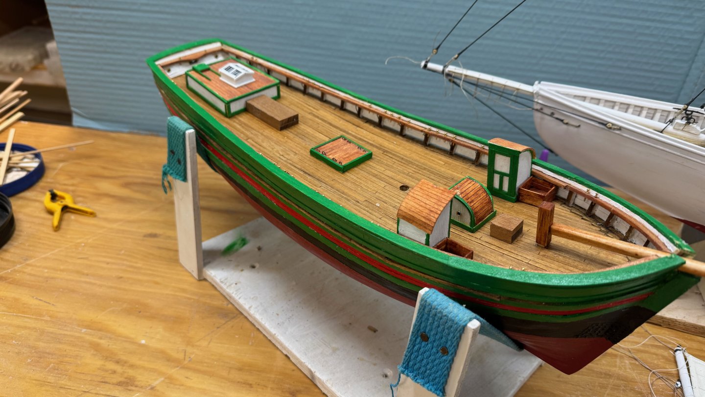
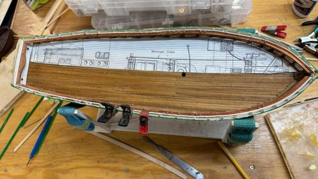
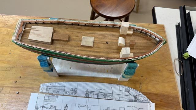
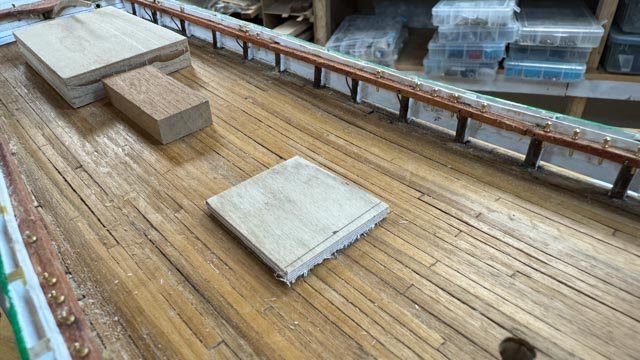
8 complete rails and plan deck work Thank you everyone for your likes. It helps keep the fire burning. This is a partial update to record completion of the cap rails and this phase…. “ the hull” . It’s kind of like topping out of a building. I suppose i could get a miniature Xmas tree and set it on the rail. I had a nice glass of Single malt and now we move on... 1,2,3 these images show the completion of the cap rails. It was pretty straight forward, as I used the rest of the milled poplar and cut out three sections for each side. Next up will be to complete the deck furniture but first I need to plan it out. I think there are three parts. First all the stationary stuff, Then the mechanical stuff then all the rigging stuff that is best to get on deck or the rails early. 4 I scaled the 1950 Model Shipway deck plan using TurboCad then cut it out to lay on deck. I then used light pencil lines to mark where things will go. I then will be using this plan and the long cross section to get dimensions. 5,6,7 these views show the progression of making up blocks to represent the stationary element. Some of these I will trim down build back up with cladding. 8-9 are just further along as the cap rail is now all painted and the 10 stationary deck pieces are laid out with some early shaping. I see in the photo I have a few more of the iron brackets to add in as supports for the shelves too. I need to get them done before setting any deck stuff. None of this first phase includes the mechanical equipment. That is a tough phase to follow as I quickly leave my comfort zone trying to make chains to actually fit on wheels etc. I am thinking about it though as I look for material. All for now.

- 61 replies
-
- 7
-
-
- Northwest passage
- Norway.
- (and 2 more)
-
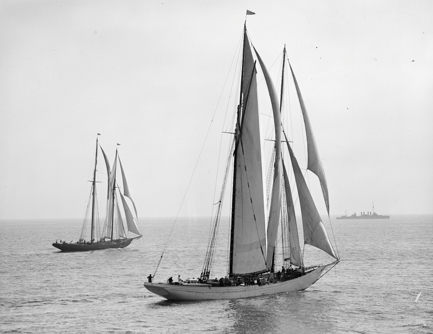
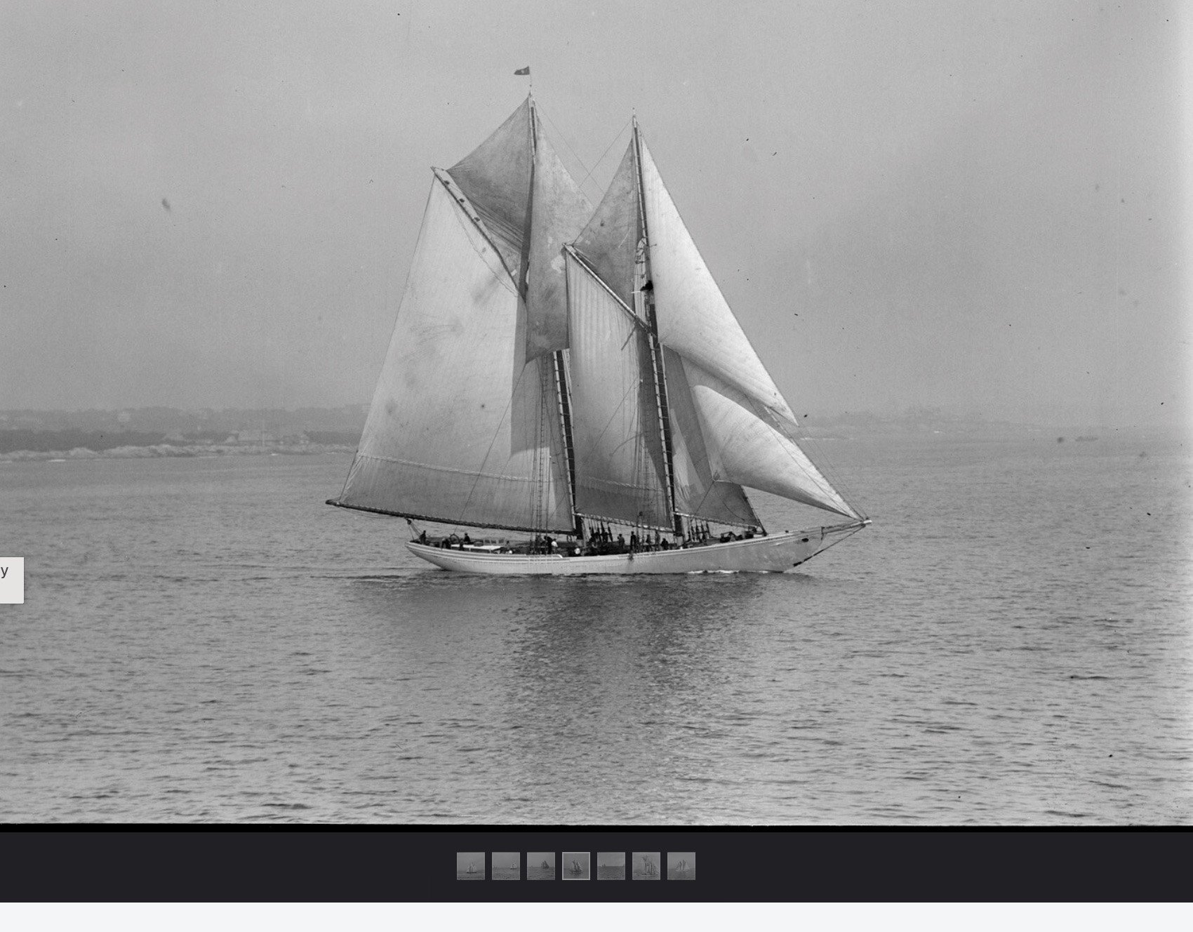
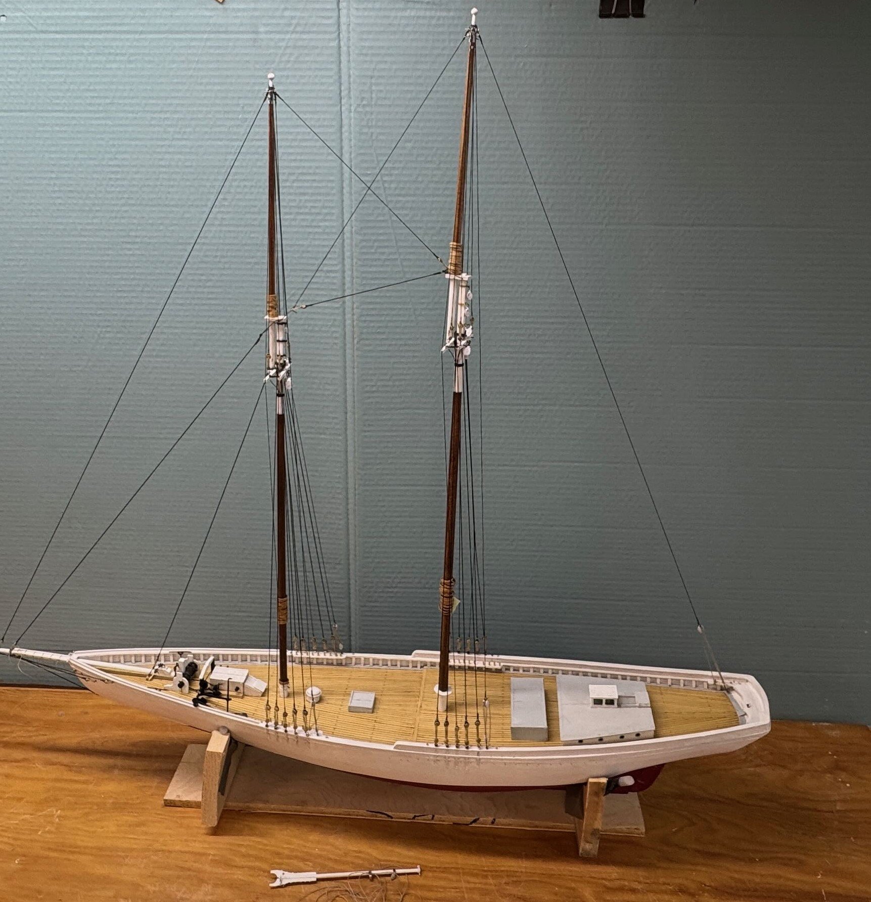
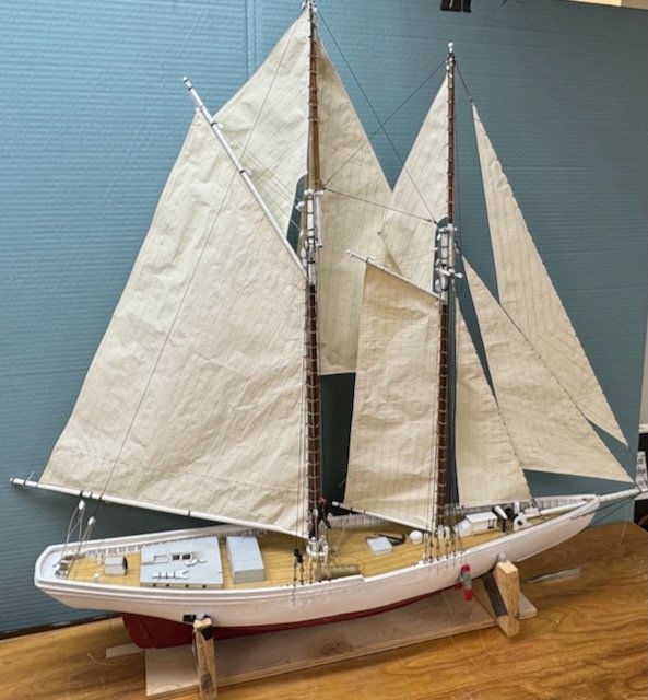
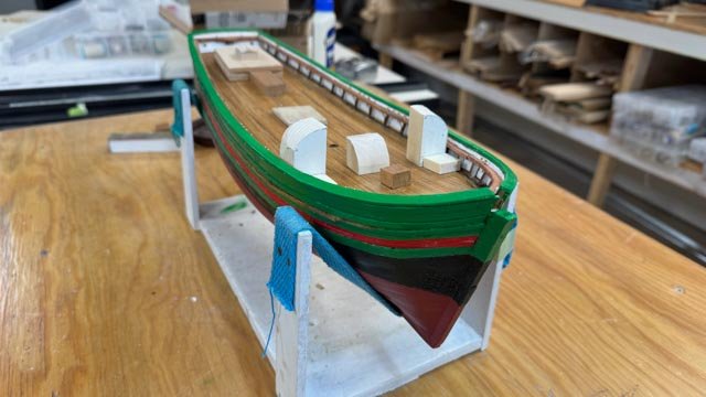
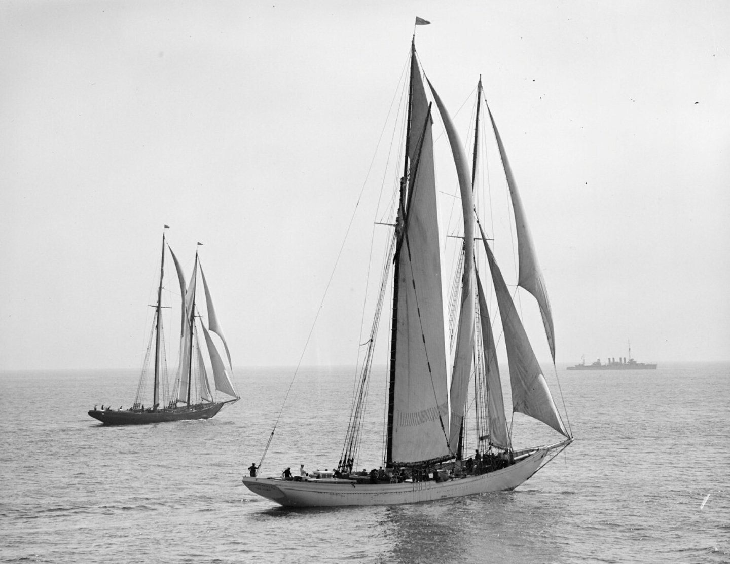
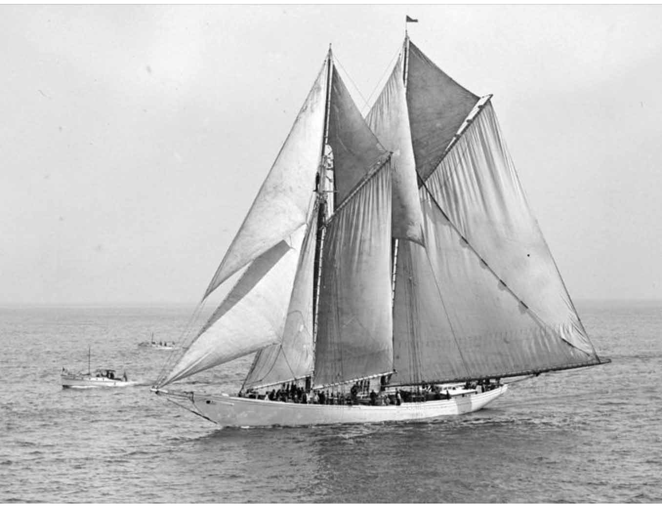
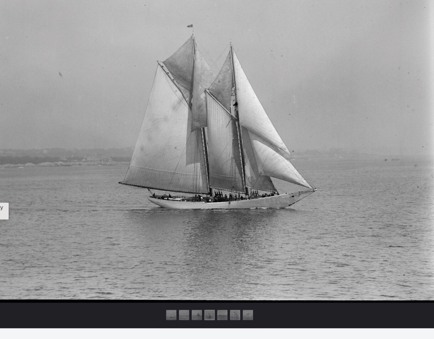
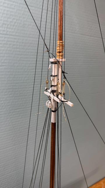
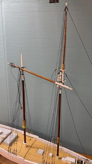
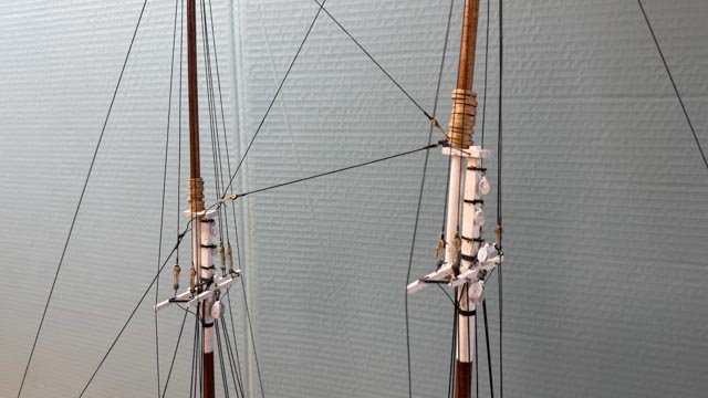
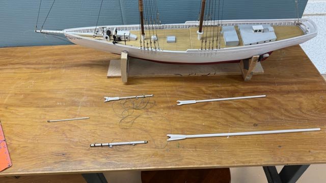
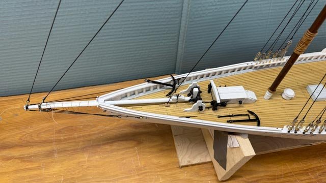
15 reset the top masts with missing rigging, as sails go through early production. 1 this view shows me carrying on from the last update, I have added the missing foremast bands and blocks for the foresail and the hoops for the fore topsail. She is back together there at least. 2 shows the main top mast disassembled for the same treatment 3-4 these views show us all back together. Going forward, I have reached the time when I need to set the stage as to how I would like to display this model. Surely as she was racing. 5-7 show three views of her that influence the intent. One option I have considered is to show the historical event where she lost her top formast in the first elimination race against henry Ford. I have researched that incident and learned that the mast did not fail but came unstepped. They rerigged it on the fly to to set horizontal but loosing both he top ails and the fisherman sail they had to retire. I will not try to do that but simply refer to the story of her closeness to glory. 8-10 these views show the production line of sails and spars. 11 this view shows an interesting option. I included the three racing photos also to document that no anchors were present while these guys raced. Thus, I may lash one to the deck, but will not hang one over the side. a final question will be how many crew do I need......I am not sure the typical collection of 4 or 5 will be enough. cheers

- 48 replies
-
- 10
-
-
John Your sequence or getting the running rigging all in place and tied down before ratlines really comes through with these images great job! jon
- 166 replies
-
- 2
-

-
-
- Red Jacket
- Marine Model Company
- (and 2 more)
-
Thank you for the recommended sources. I down loaded the Norwegian article and just ran through it. lots of great images to go over more closely. i have those model shipway plans as that is my basis. hopefully my pins are in the right places! I ordered the book too. As I have said before, I will have an incredible library one of these days. becoming very complete. cheers Jon
-
Wow what a great study on the rigging . I will be following every post as I am totally out of my comfort zone with Norwegian rigging. Great work and I look forward to your progress Cheers jon