Jond
-
Posts
874 -
Joined
-
Last visited
Content Type
Profiles
Forums
Gallery
Events
Everything posted by Jond
-
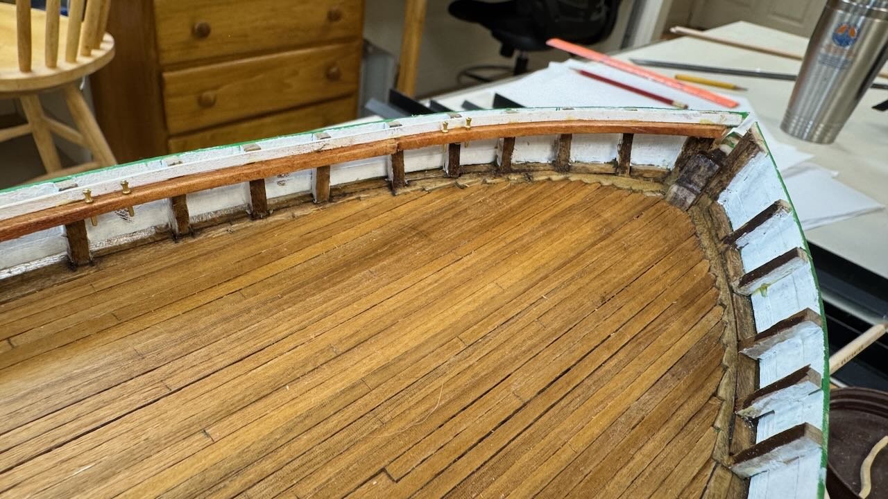
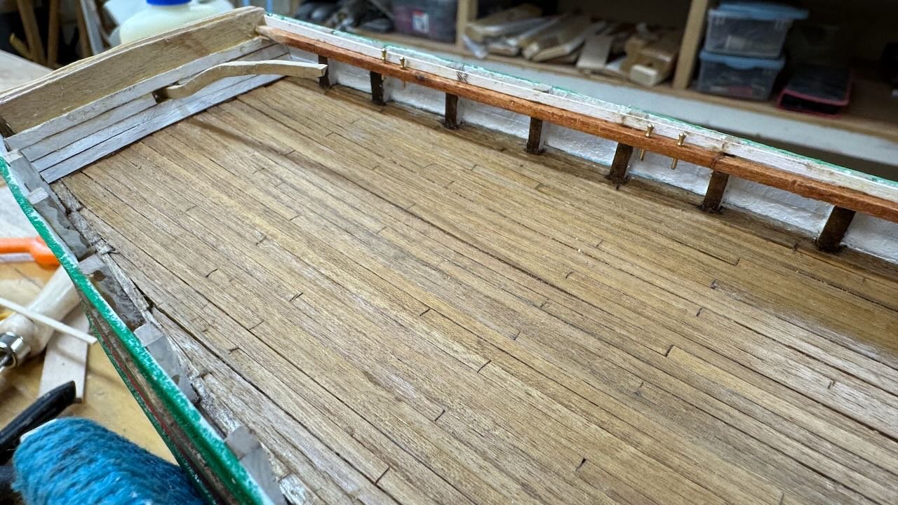
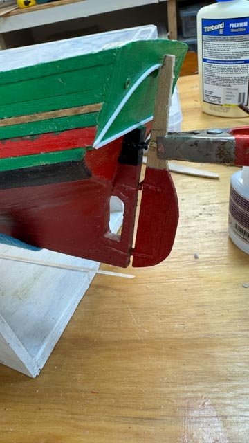
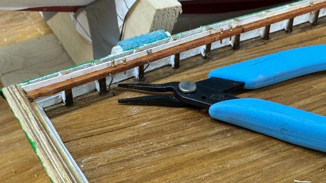
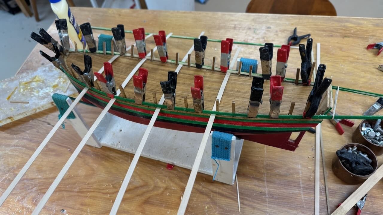
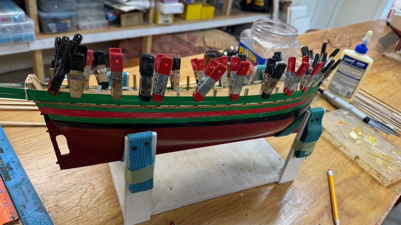
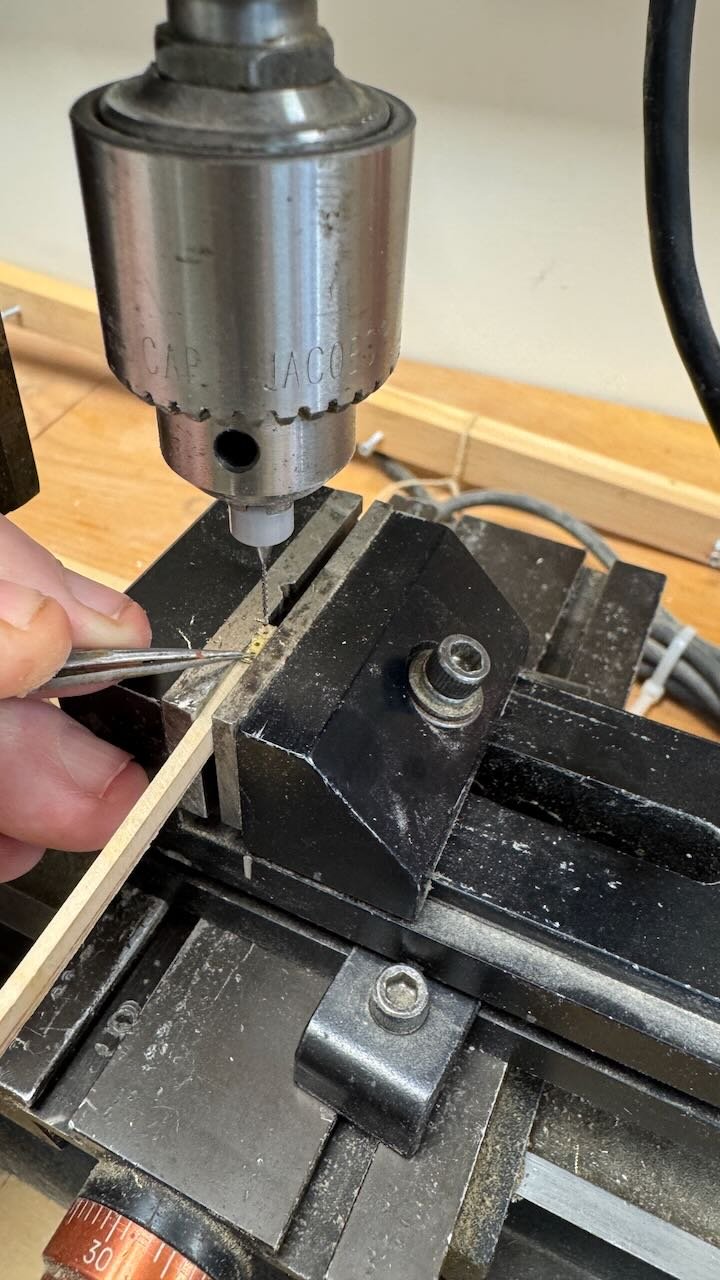
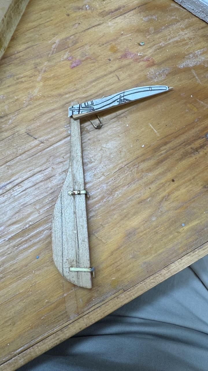
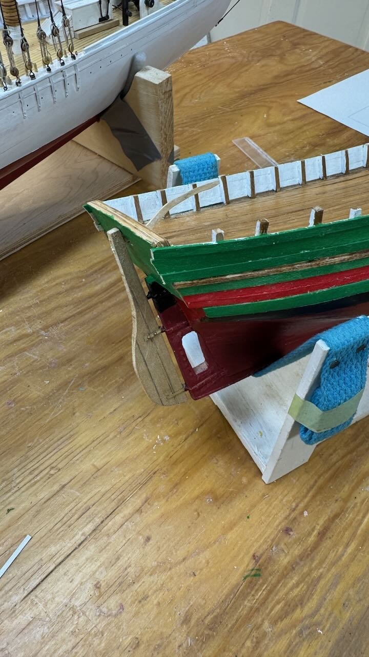
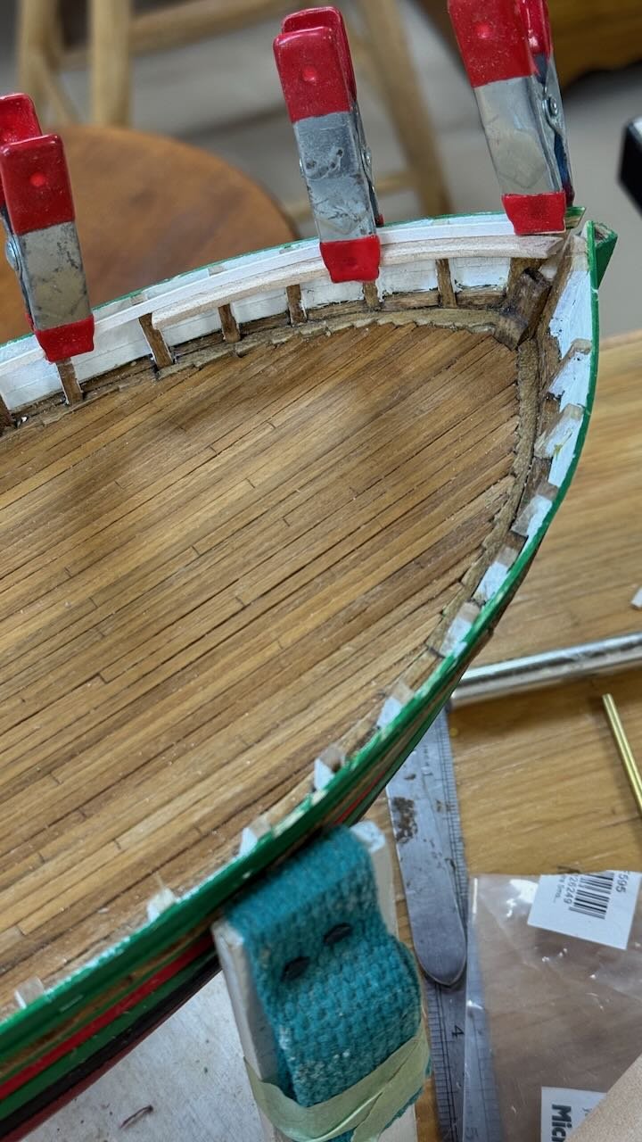
 Gjoa 7. Complete rudder and bulwark "shelf" This week I have been able to get a few things done. I am about the middle of this stage and planning for the next one. 1-4. these four view show getting replacement drill bits, so I can complete the last pintel, and the laying out of the tiller by scaling a drawing. I have a few sheets of pear wood that are great for this type of detail work. The third and forth view show installation and the trimmed-out transom. I keep learning the hard way how critical it is to stabilize things like brass strips when drilling tiny holes. I have broken many drill bits. 5 this view is a group of new poplar strips I milled to use for both the bulwark shelf and cap rails. 6-9 show the progress of the shelf 10-11. these views show all the belaying pins are in and the steel rod shelf supports are going in. I am thinking to keep the brass pins brass. I know they should be darker but I like the look. Next up will include the cap rails. And planning for deck furnishings


- 55 replies
-
- 6
-

-

-
- Northwest passage
- Norway.
- (and 2 more)
-
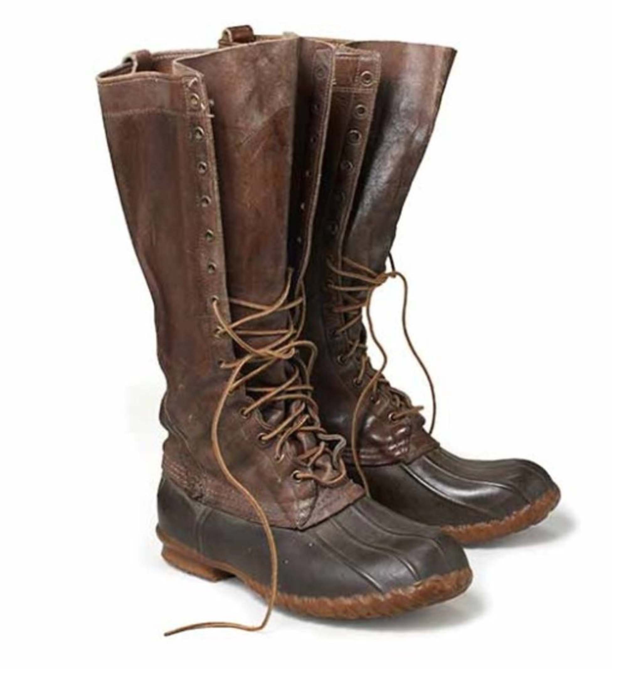
Thank you wefalck for the incite to the slot. I am sure you are right about the rubber boots too. Let me introduce you to a famous Maine boot first made in 1912. These are the L L Bean boots that even today are extremely popular. We in Maine all where a version of them around here over the next several months. The lined ne for snow and the unlined are especially popular in spring. I will admit however our outside durations do not approach the conditions of these brave explorers or fisherman either. cheers

- 55 replies
-
- 2
-
-
- Northwest passage
- Norway.
- (and 2 more)
-
John You need also to thank the Norwegian builders that chose it. I think it would be very practical on a fishing vessel. Think of all the mess while working and little holes by each rib and one trap door for fish guts on the typical Gloucester fisherman. Perhaps this open slot means more water on deck when healing over in a blow, but the crew all wore rubber boots anyway.
- 55 replies
-
- 2
-
-
- Northwest passage
- Norway.
- (and 2 more)
-
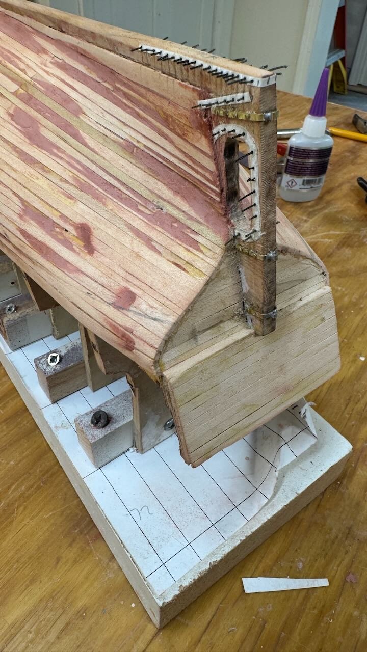
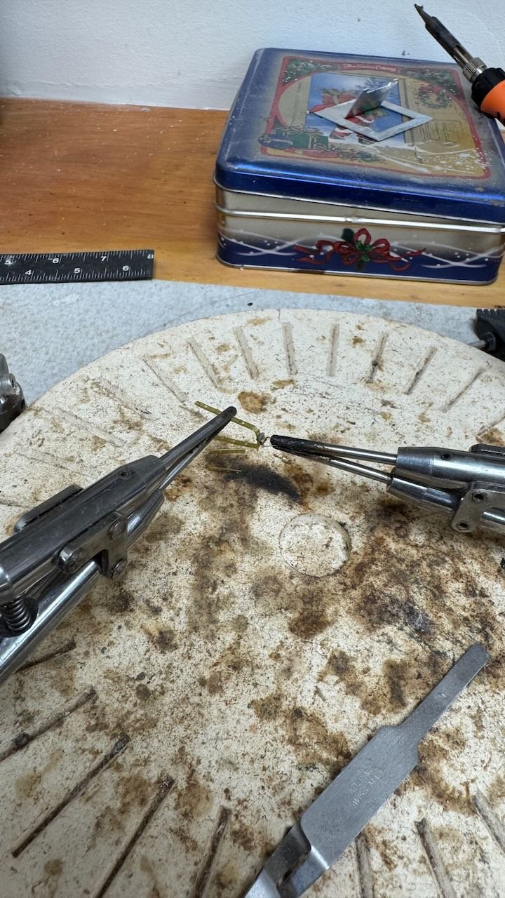
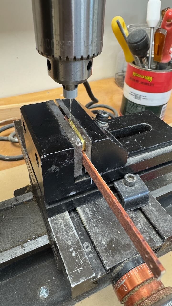
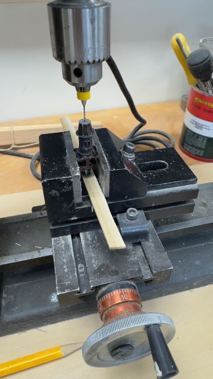
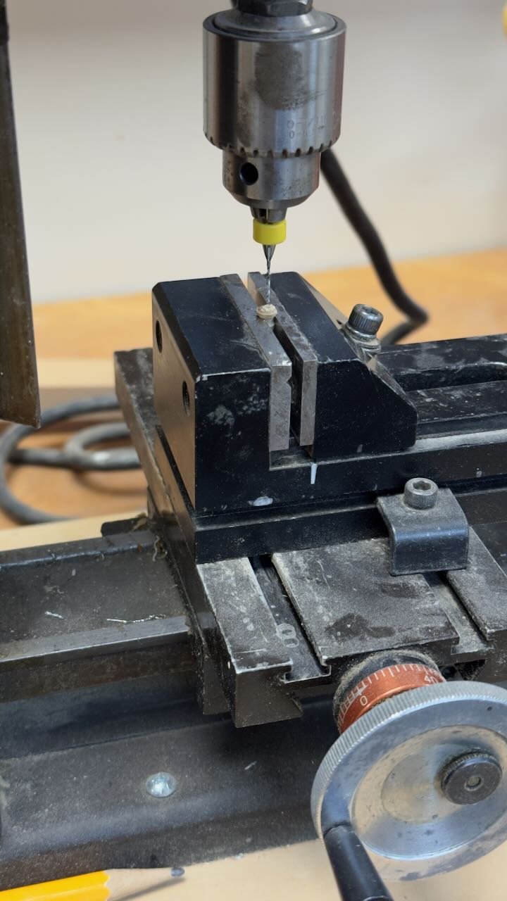
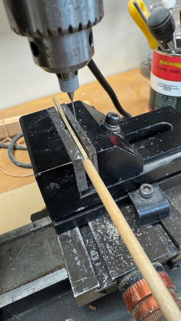
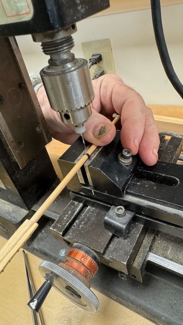
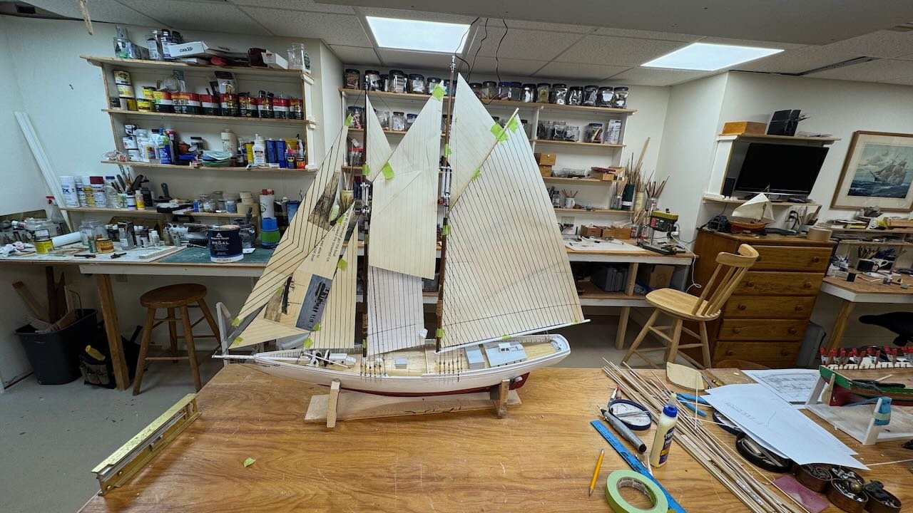
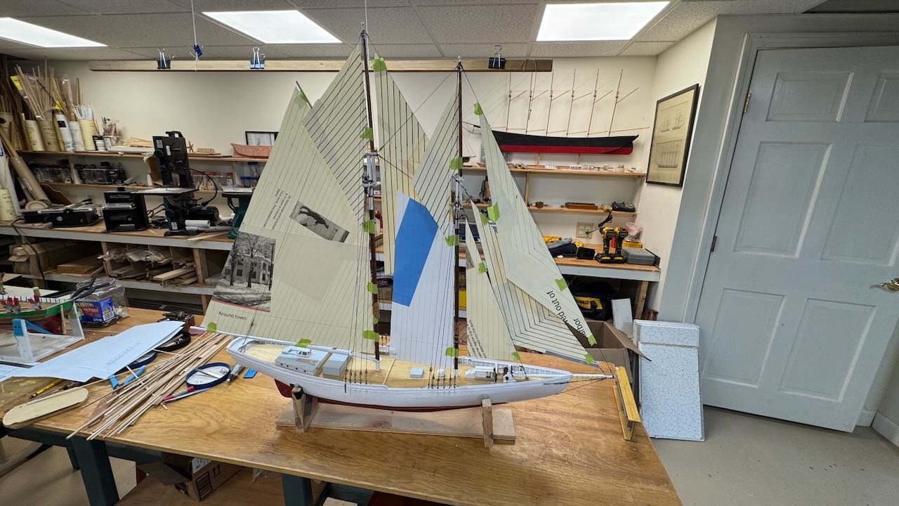
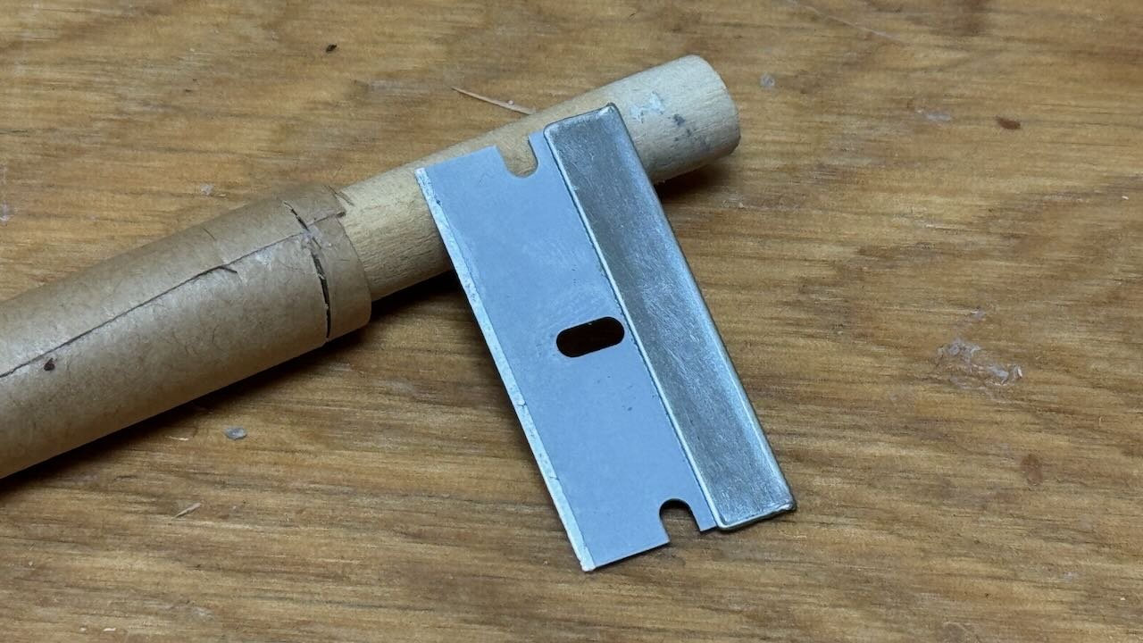
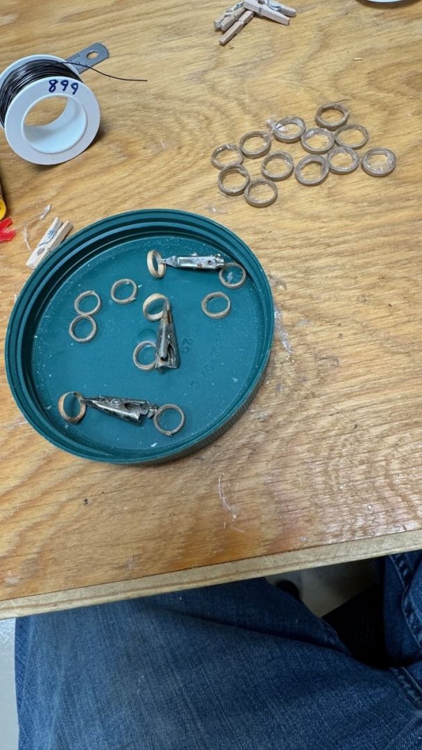
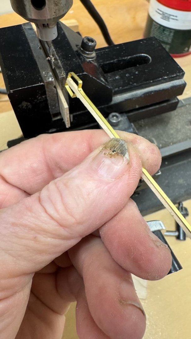
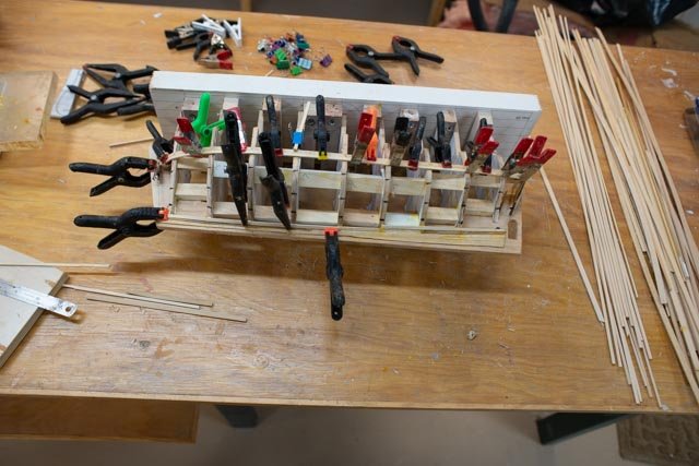
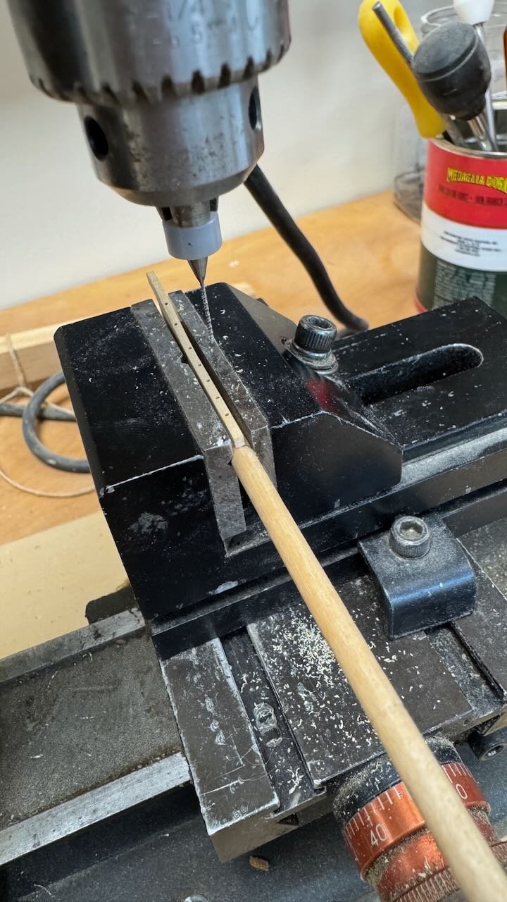
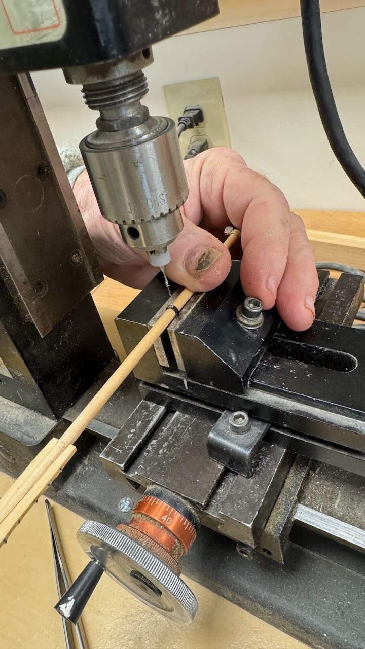
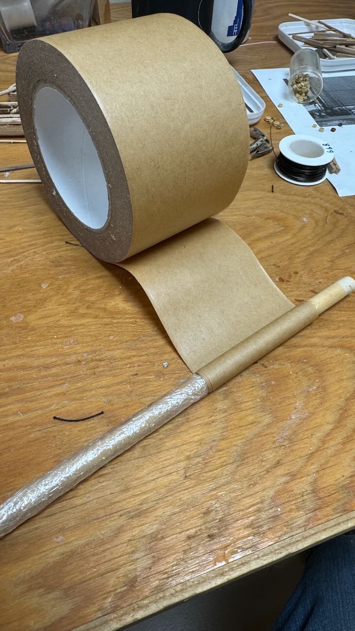
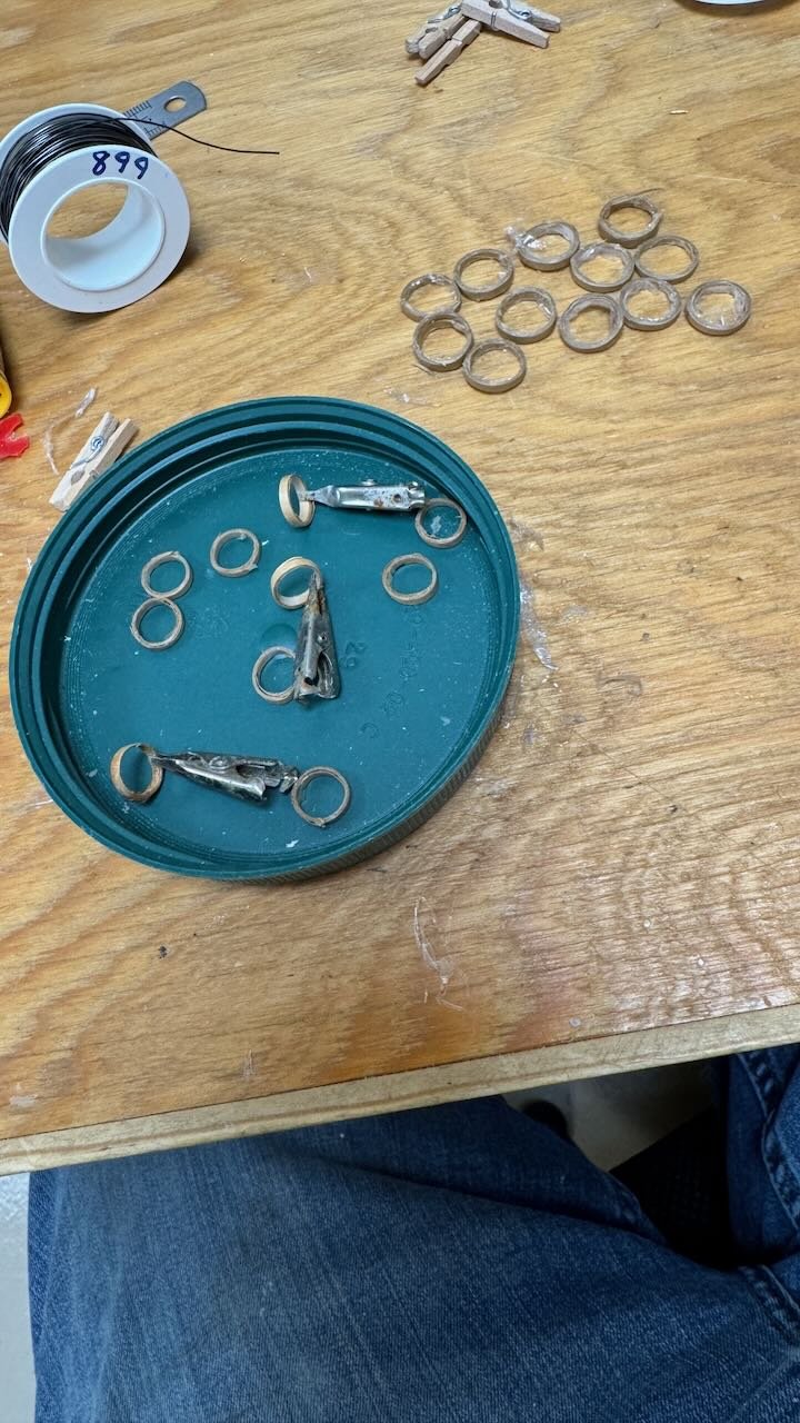
14 getting all the spars ready for sails Over the next month I hope the 8 sails will get made. In a parallel effort they need the spars for lashing and all the running rigging lines that need to go on before installation. Example would be the boom tackles or topsail clewlines, that are much harder to install on board, should go onto sails before they are rigged. A halyard could go on the sail or the gaff before but I find it easier after for the peak halyards to a gaff. During the holiday, the sail patterns were made, and dry fit for adjustment. Since dimensions were taken from scaling photos, I was not surprised that every sail needed something trimmed; usually cut down. 1-2 show the patterns all made and after adjusting held in place for a look see. They were taken off as soon as the photo was taken. 3 -4 show that the top masts need to come back off [cutting and removal of dead eye lashing on top mast shrouds and other stay lashing needed. Dressing of the masts include bands and blocks at the top of the lower masts, hoops for the upper masts and more running rigging needed to be done before reassembly. This effort was understood to allow the timing for the sail making process that my daughter likes to do when she comes for vacation. Otherwise, the complete dressing of the spars would have been completed first. 5,6 ,7 show my selected process to make top mast hoops. I like to use 1/64 birch plywood strips for larger hoops, but found coiled packing tape over saran wrap on a Dowel of the selected diameter works well. I use a simple razor blade to trim off say 10 or 12 hoops. They then get coated in varnish and some need a little AC glue to tighten up the ends. This roil of tape will outlast my work by a century. The uncut tape stays on the dowel so I have about 4 diffewrne sizes waiting for the next job......sound familiar? 8,9,10 show my low-tech use of a mini mill to drill more accurate holes. Three images are the pear wood I chose for the jaws getting drilled for monofilament simulated bolts and the gaff band holes. View 4 is a foresail mast peal halyard ring getting drilled to hold a halyard block. all for now...first snow is predicted, let's see if it happens


-
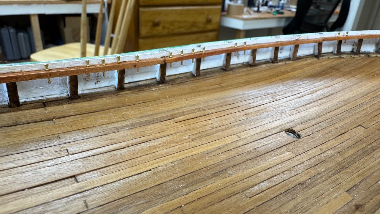
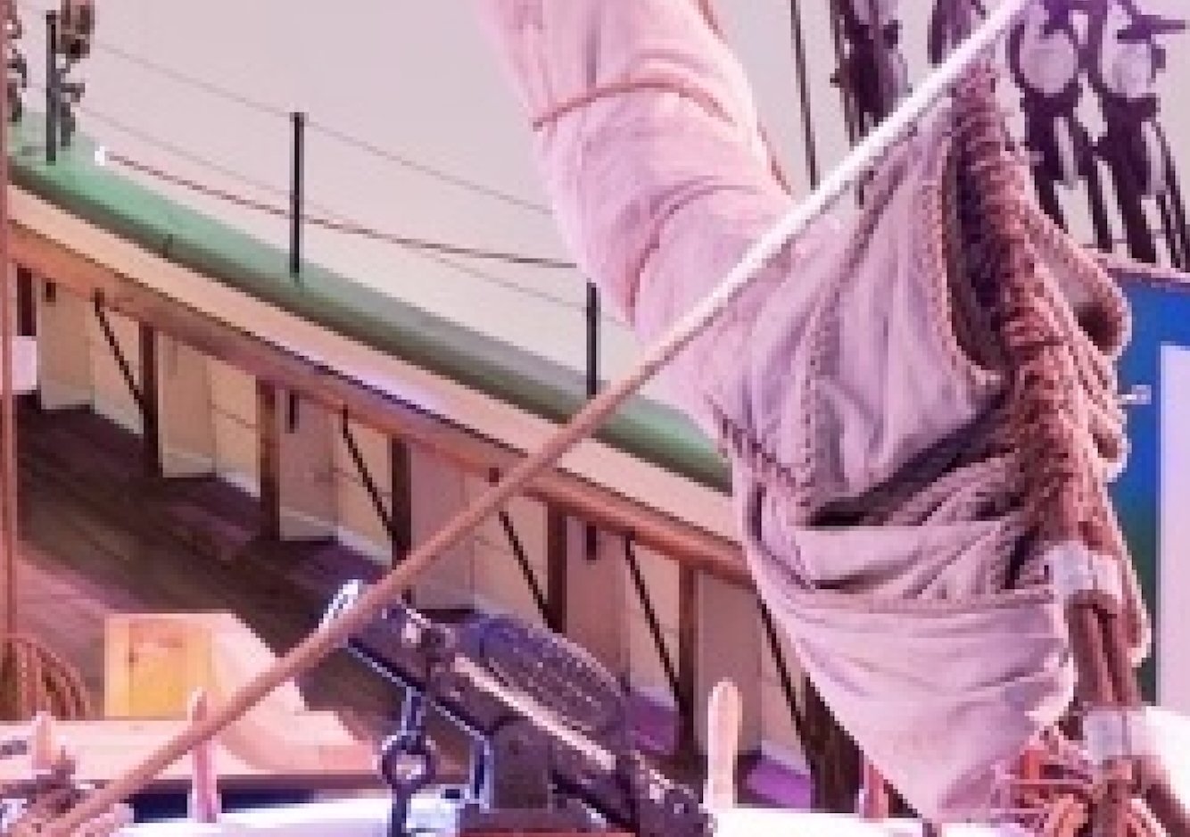
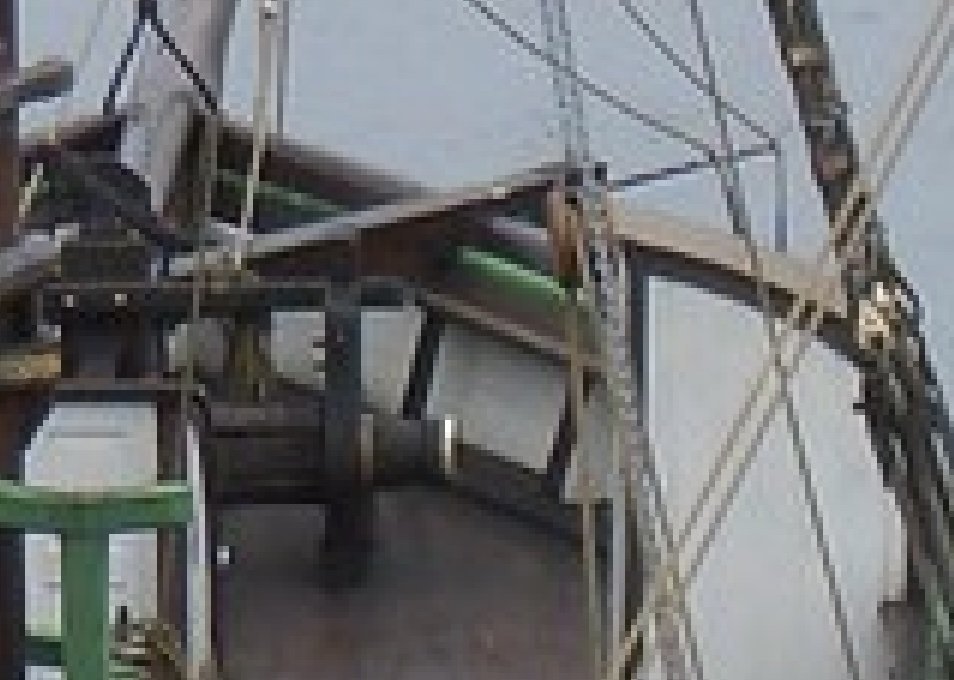
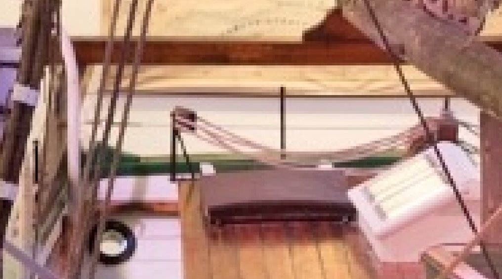
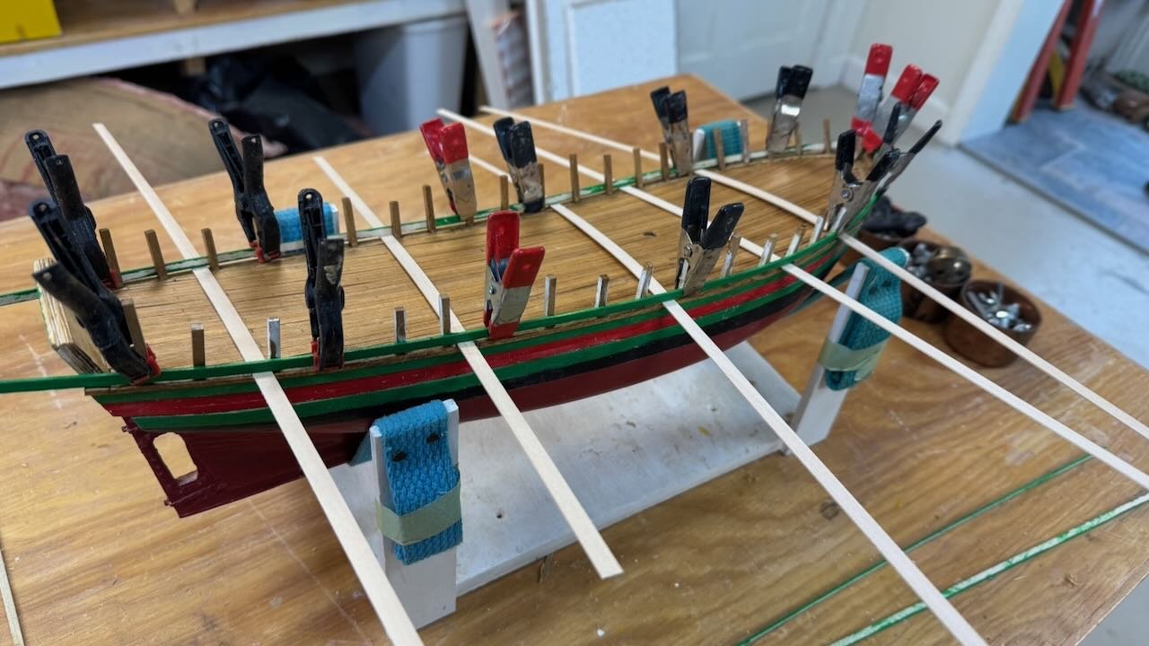
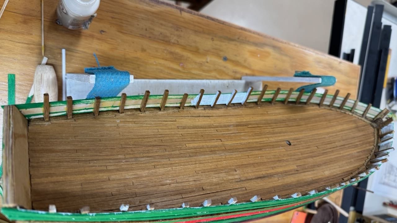
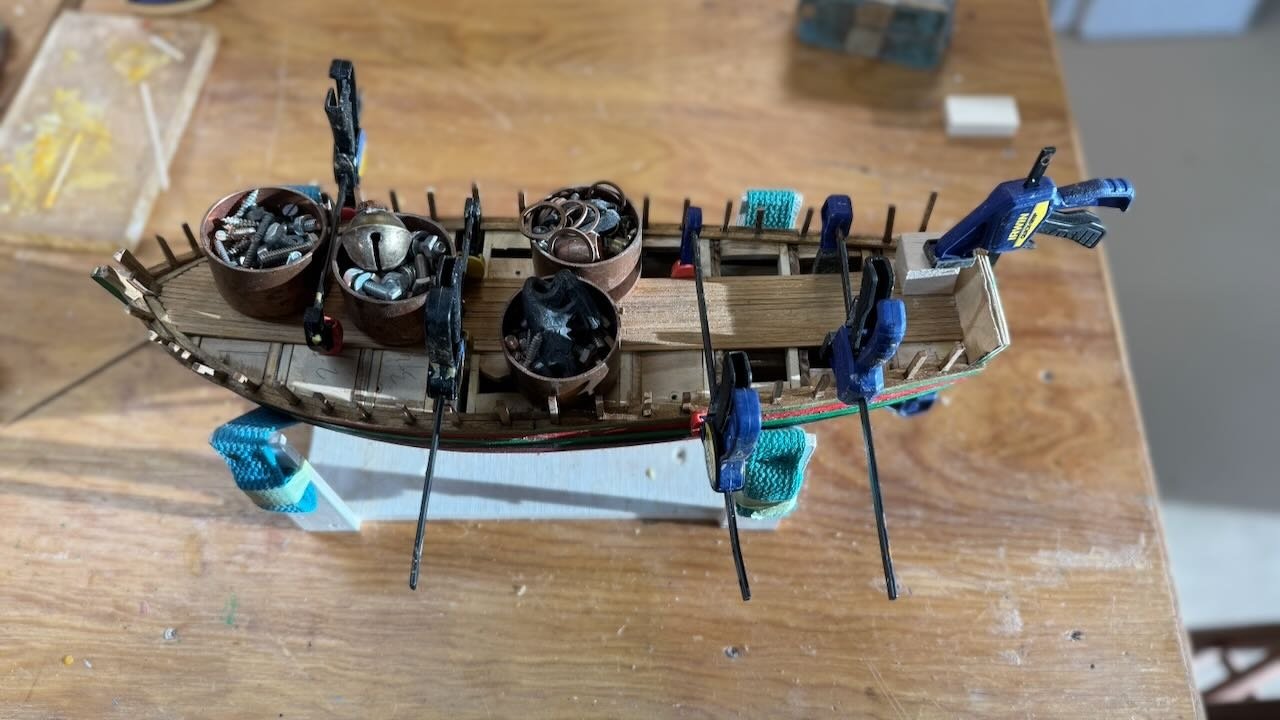
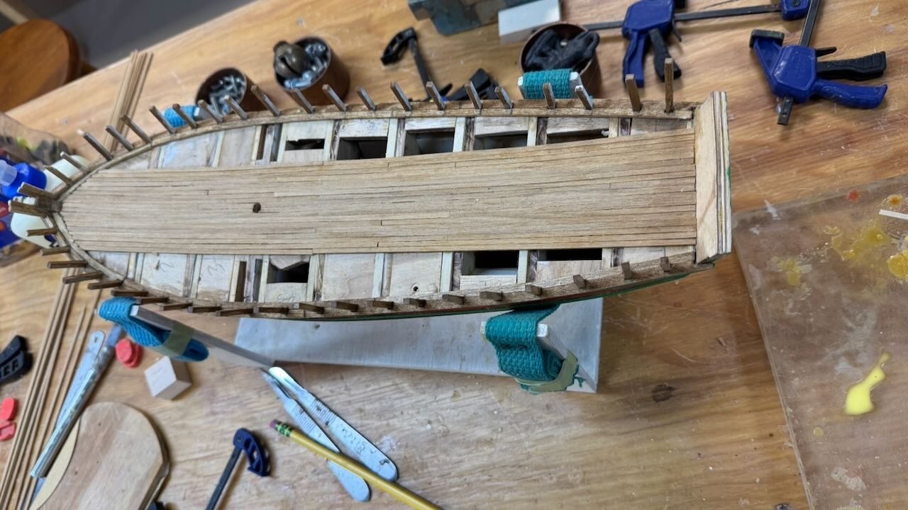
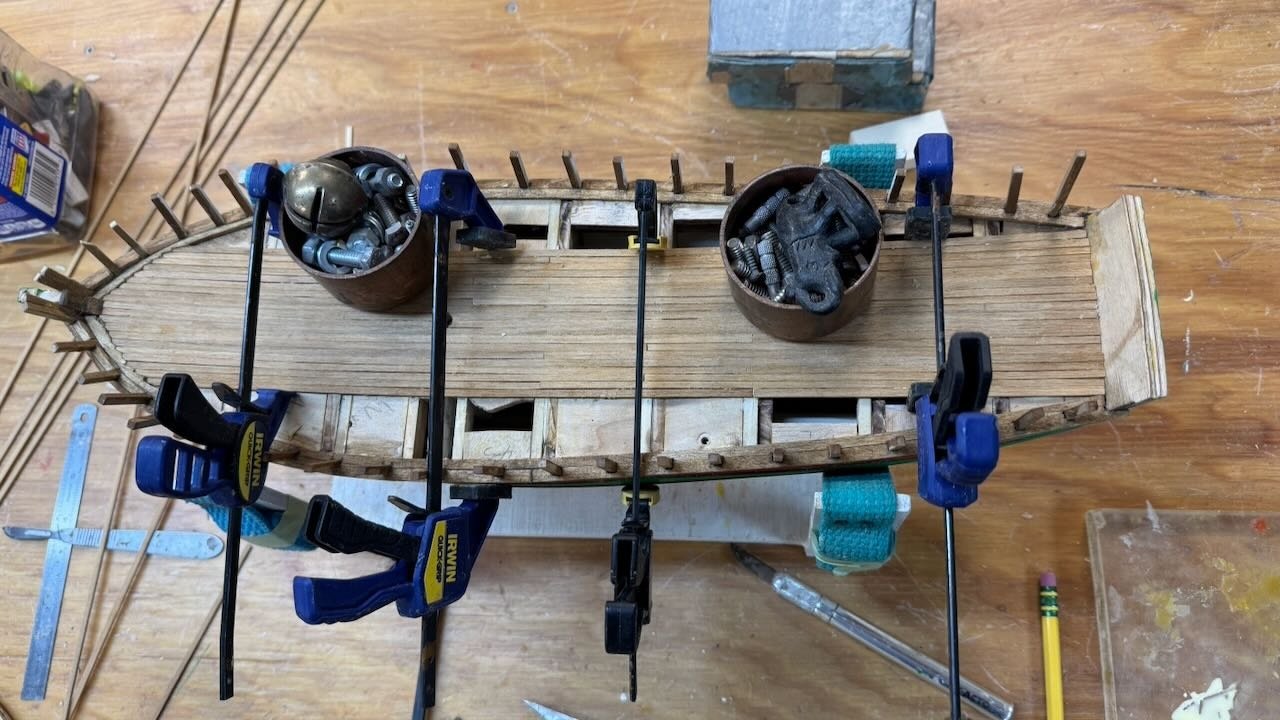
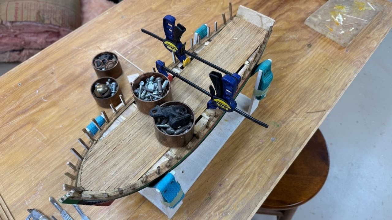
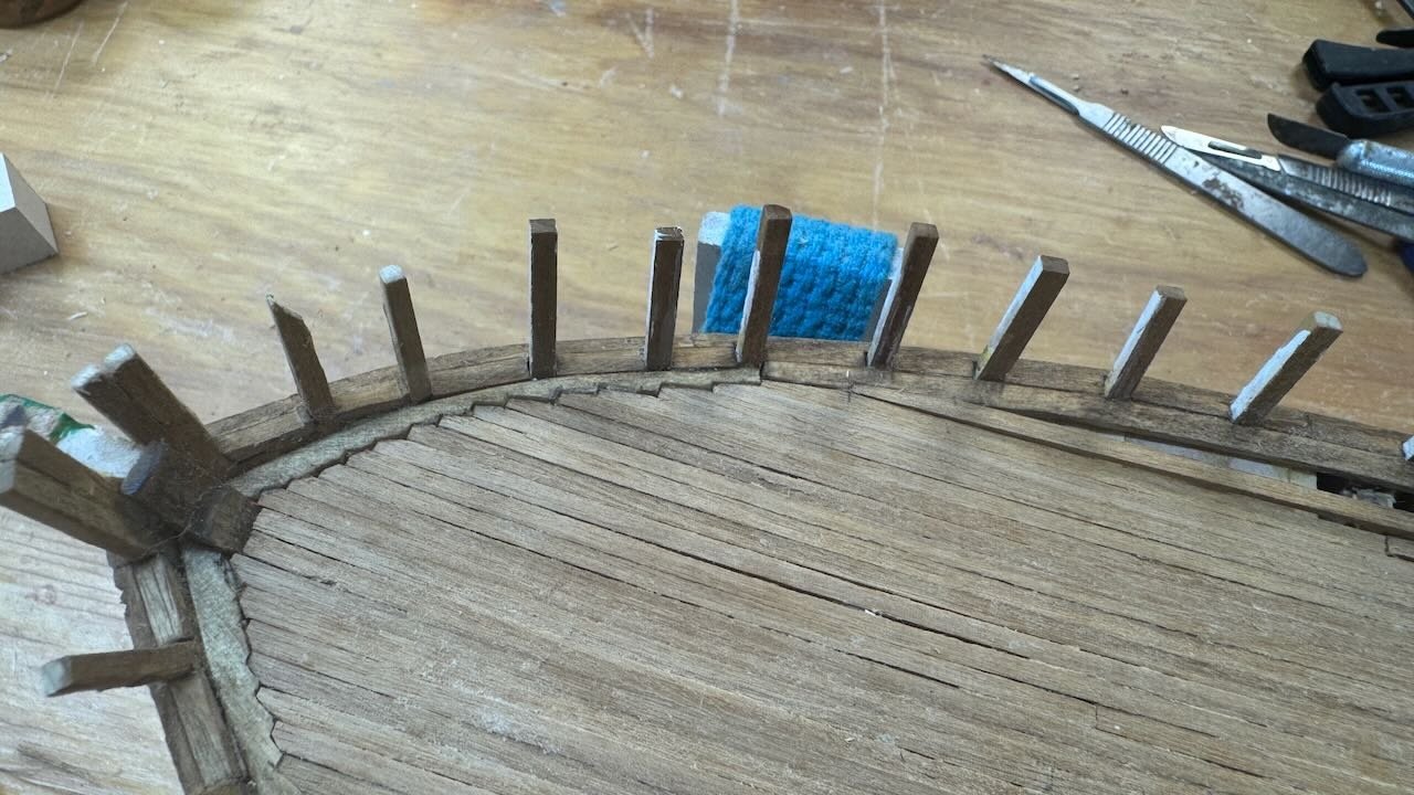
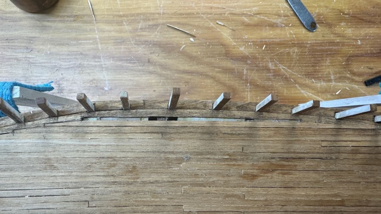
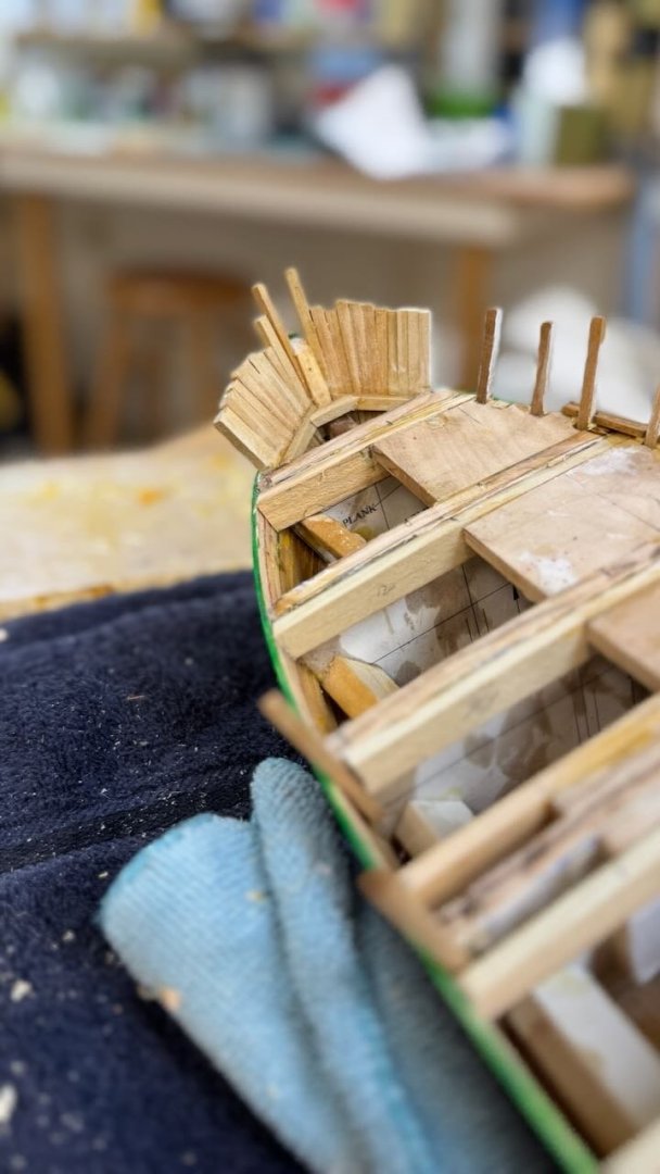
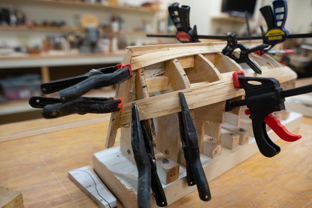
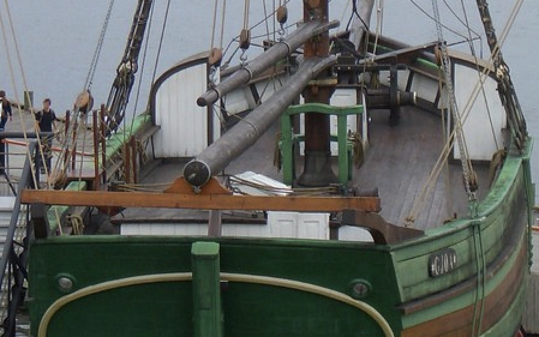
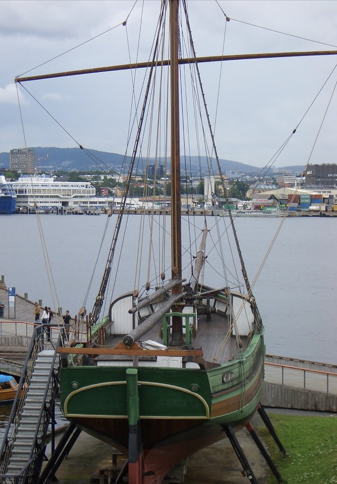
6b continued review of planning for work on deck Thank you again Wefalk. I continue on a fun search. Continuing to review images and to try to determine what to build is a fun part of this work. I may not get it all right, but at least I try. The first two Museum photos from the net: 1-2-3 here is a view over the deck from the bow. Second is a blow up of the port side mid deck and bulwark at the museum followed by a cropped version. In this image, the inside face of the raised ribs is oiled or stained or whatever. The rib sides only are painted white with the inside of the bulwark strakes. Then there is a continuous oiled “shelf” with black iron supports on many but not all the frames. I assume the shelf doubles as the pin rail where needed. The 1950 plan I have concurs with this assumption. The third image carries to the transom. My plan is to follow this approach. We’ll see how it goes. 4-5-6 view of deck from the stern with blow up and cropped version showing again a stained face of rib and no small deck between the stem and cat head. This view also confirms my choice to use a darker wood for the deck material. Anyway the journey is fun and learning the stories that go with this build is more to my purpose. I read Amundsen’s book and now am reading Sverdrup’s adventures. I find it hard to imagine living on one of these boats for 3 years. Progress 7-10 here the bulwark goes in plank at a time. In the first two images I use strips to create the continuous scupper, The 4th image shows starting the delicate job to paint the inside of the bulwarks and sides only of the ribs white,


- 55 replies
-
- 7
-
-
-
- Northwest passage
- Norway.
- (and 2 more)
-
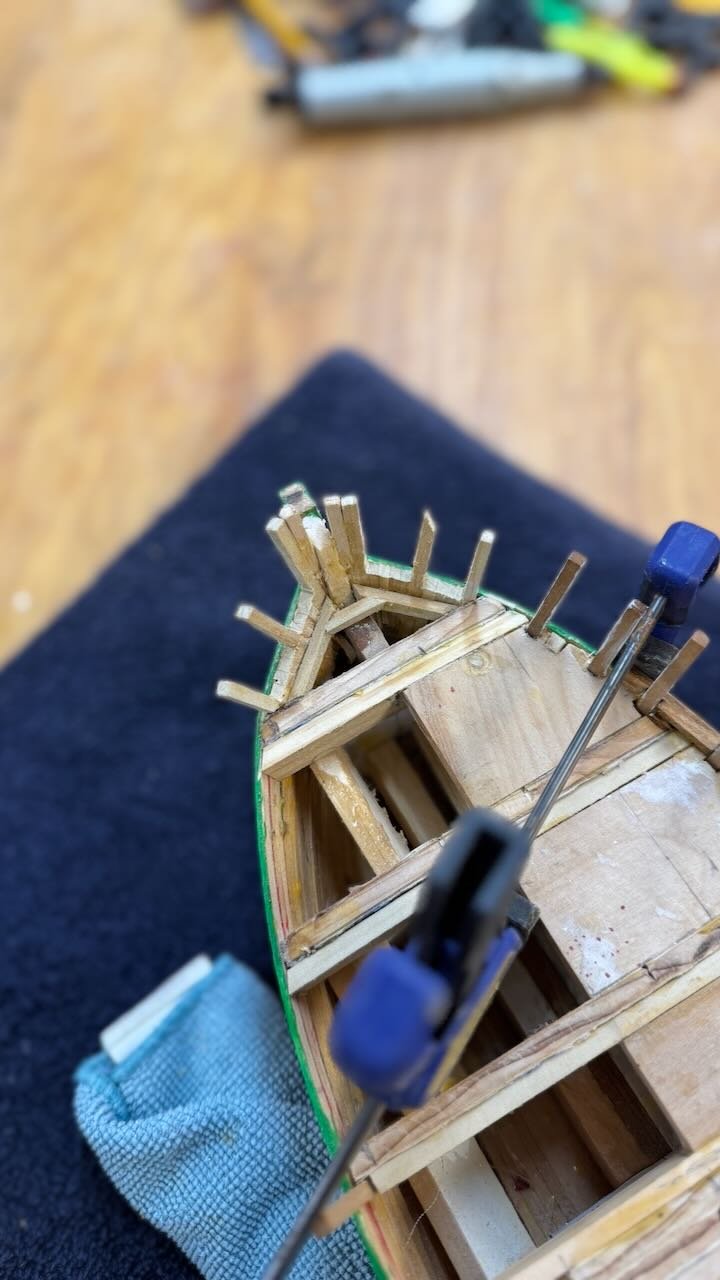
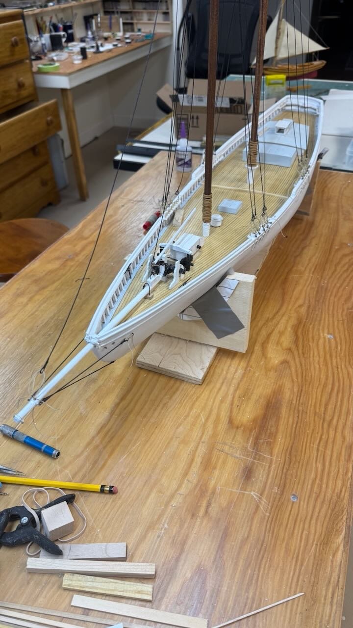
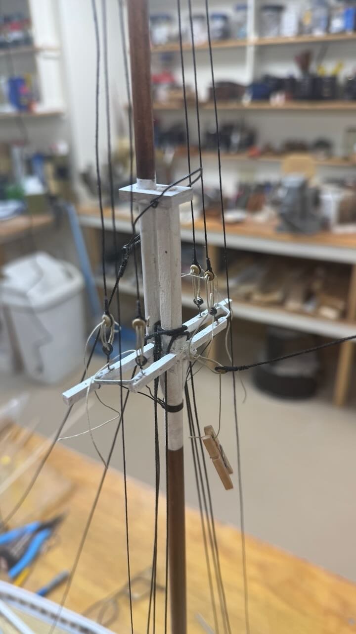
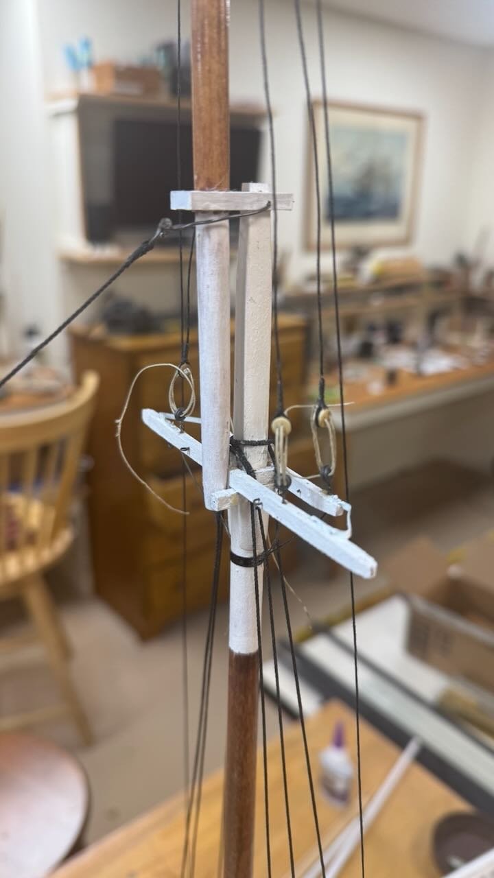
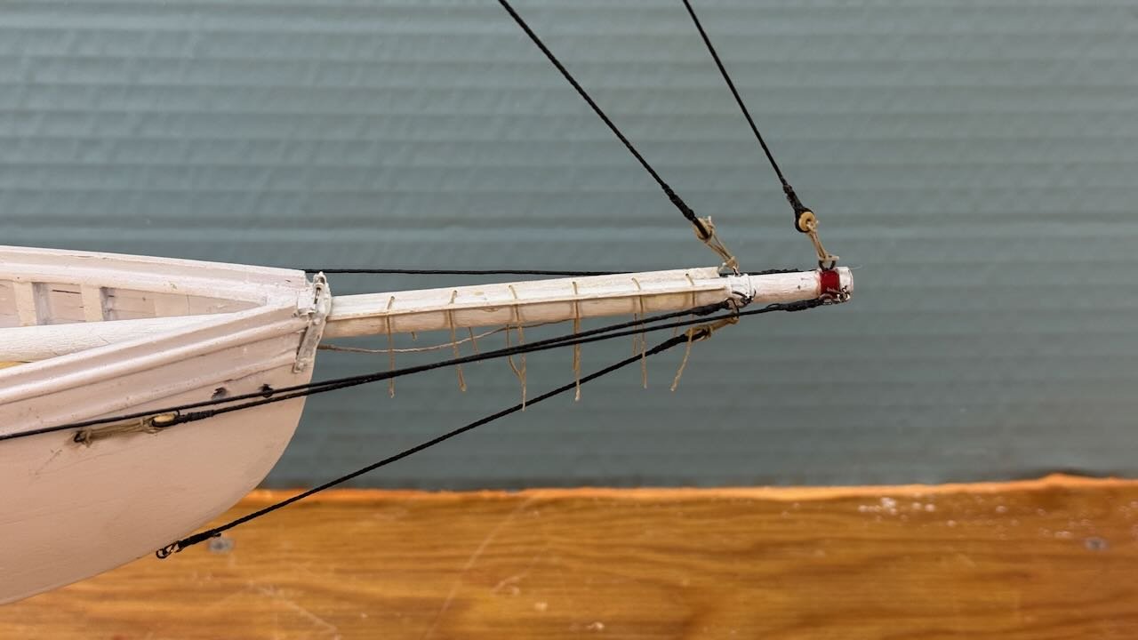
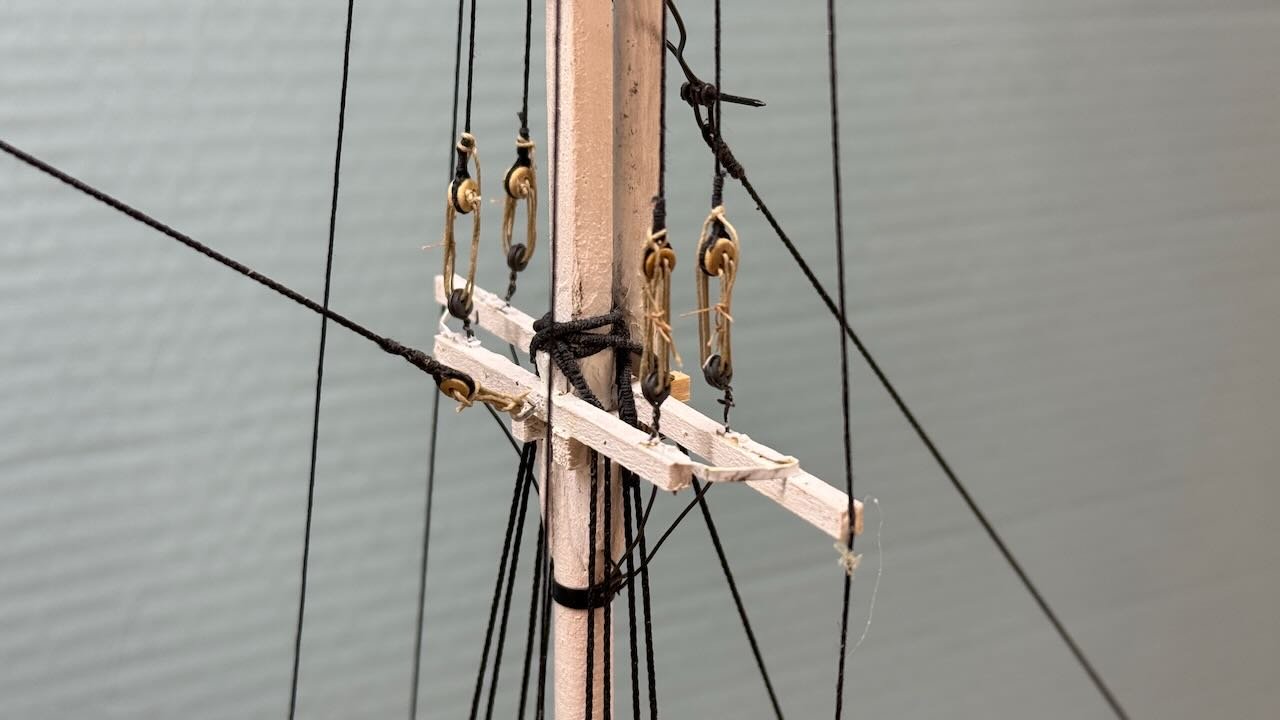
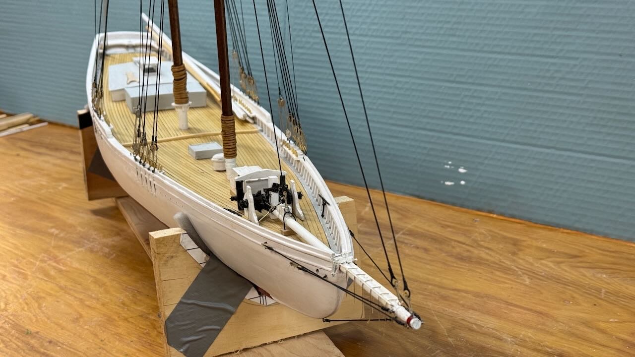
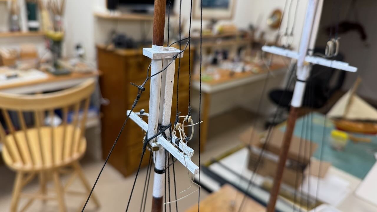
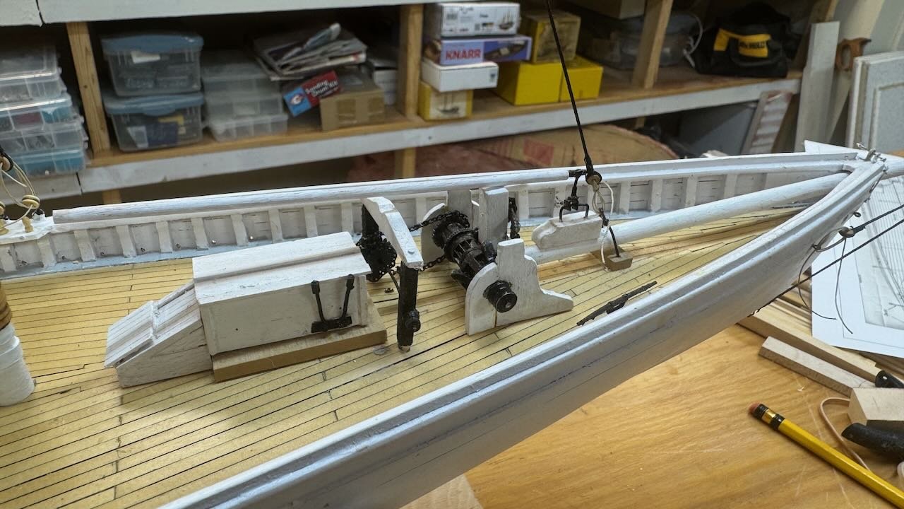
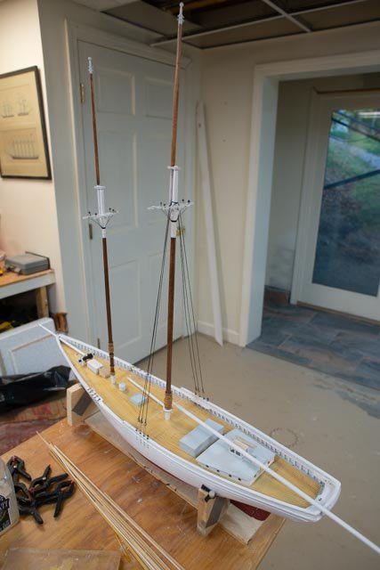
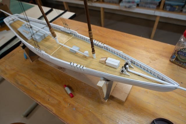
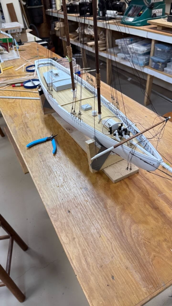
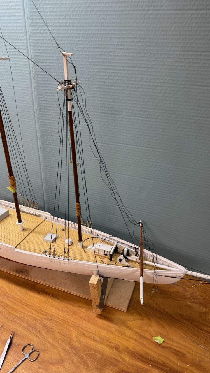
13B Standing rigging done I have been working to get the standing rigging and spars all done, so as my daughter comes for Thanksgiving, we might have fun making sails. Her friend flew in from Arizona, so we have two helpers…oh boy. 1-3. The first three images are overall views just to record we are done. The main back stay on starboard is aft as we will display the schooner sailing on starboard tack. Without any sails up and sheets and preventers holding things down, it is the only line holding it all rigid. 4 -5 show the foremast starboard side all secured. next up of course are the ratlines. 6-7 show the bow sprit. This sprit was only added for racing. The foot ropes need to be completed. I have the furling tie offs. A detail I learned about while visiting Bluenose II. The planks to catch the sail and the preset lanyards to secure the sail make lots of sense. This rig is a racing rig as the scene to be set is the first elimination race against the Henry Ford , October 13,1922 When not racing the bowsprit was not even rigged as she was launched to be a knockabout schooner. 8. just a tease as the first sail is progressing through the assembly line. I need to finish up all the spars, so they are ready when the sails get done. This sequence of rushing to secure and fasten everything is not a great sequence if rework is to be avoided. Once the patterns are done and test fitted for adjustments to allow sail making, there will be some disassembly needed. that will come in the next update. cheers
.thumb.jpeg.e22c9d3f9843a74dc6cabf838daeca3c.jpeg)
.thumb.jpeg.627735a403074c447f7782bd6f3df5ac.jpeg)
.thumb.jpeg.781f0bace0370ee7a4713e30e36c1844.jpeg)
.jpeg.b974ff82d0881a9bb55232195688170b.jpeg)
-
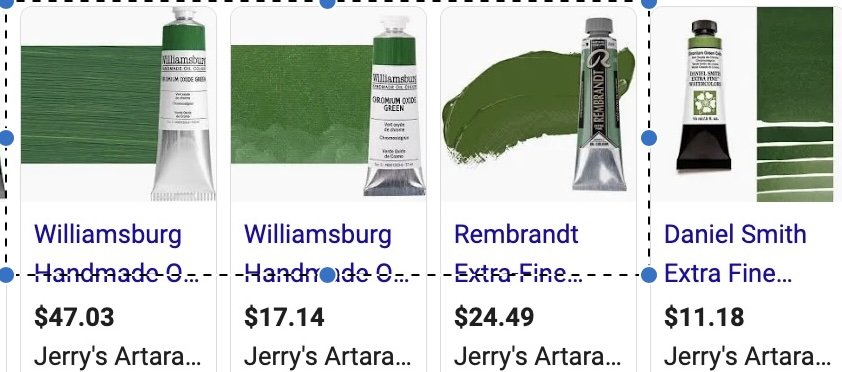
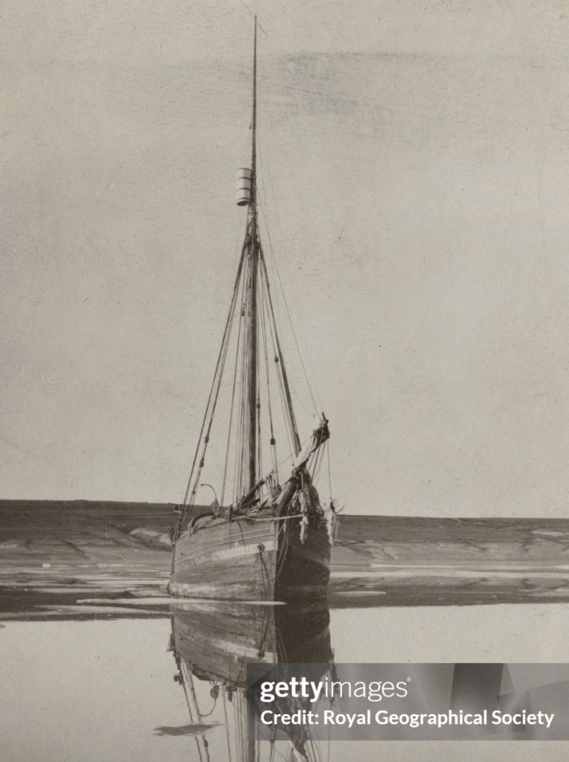
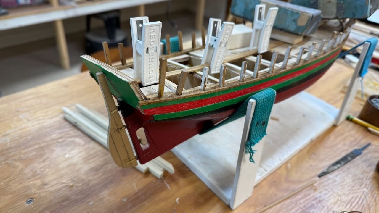
Dear Wefalck It is always an honor to get someone with your experience to drop in. I appreciated getting your thoughts and have spent the Holiday both eating too much turkey and musing on the idea of chromium oxide green paint. I went online to look it up and could see that your call is surely righter than mine. Over the last few days, I have surfed the net looking at many more Gjoa images. Here are a few from my growing collection that led to where I am.... and I am actually “sitting on the fence”. 1 here is an image of the artist paints of chromium oxide green. I can just see the 19th century coming off the page. 2 here is another outside image of the museum painting....without funny lights 3-4 here are two internet images of paintings that show green and reddish strakes. In one clearly light green in the other is in shadow. 5-6 here is a black and white image from San Francisco. I believe it was as they were loading her on to the ship to return to Norway. That paint was clearly fresh, but considering this second Getty internet image from 1903, might have been more right....thus my fence sitting. So what to do? My limited experience with the likes of Mystic Seaport and other US museums is to trust their selection. I agree with you that in pictures with the museum lighting are interesting to say the least. So as of now I am not set in stone but tentatively moving ahead with my two colors. I want to be clear it is not because I feel I know anything about Norwegian painting 1880-1900. I look to the Fram Museum choices and attempt only be reasonable to follow their work. I would love to visit there but wow it is there! Was the San Francisco white paint the correct image...I have no idea. I could still paint over the red strakes. I suppose I could get the more historic green too. Thanks for your insight. I always welcome advice. If you really think I should get a tube of chromium oxide green however, I could do that. Next up is to discuss the on deck painting scheme. jon
-
5b. Complete the deck in time for Thanksgiving Many of us at this stage of life get invaded by offspring over Thanksgiving and Christmas Holidays. Therefore, it is good I have found to get to a good breaking point. Then whatever gets done over the holidays is a bonus. My Daughter is coming, and she enjoys making sails, so I hope our efforts get to the Schooner build and we make good progress there. For this update we get the second half of the deck build done. 1-3. The first three views are getting the inside shear planks installed. I decided to use bass wood because I was going to have to nip every end of every plank other than the transom. Holding them down was fun. I have stained them using a light walnut color. 4-9. these views are just progressive shots showing the planks going in. I have selected to use up stock of walnut strips. I have no idea where they came from, I am sure that is not unusual. They are a bit rough on the edges, but I think that is OK for a Northern fishing vessel that has a hard life in the arctic. We’ll see. 10. shows the bow area. 11 12 shows no matter how hard you work the last plank on either side is a bear. 13 shows all planks in. Now to clean them up some and get all the cut lines- butt ends cut in. 14-15. we always make choices of how to finish things. Often, I have used basswood and then stained and used tung oil. Here I have the walnut, and I chose to use hand rub poly. The Bulwarks and a lot of deck furnishings will be painted white and green, so I hope the bold look of walnut will work fine. The Poly is still wet in the photo. Happy Thanksgiving
- 55 replies
-
- 7
-
-
-
- Northwest passage
- Norway.
- (and 2 more)
-
Thanks John for dropping in. Yes it is great that Jim has rejoined our group. In past years he always had incredible builds and very valuable advise especially for folks like me learning our way. I must say the work you do on Red Jacket is beyond belief sometimes. It's just great to watch and see when you bring her along. Both of my builds are 1:48, so I can at least see the blocks cheers
- 55 replies
-
- 2
-
-
- Northwest passage
- Norway.
- (and 2 more)
-
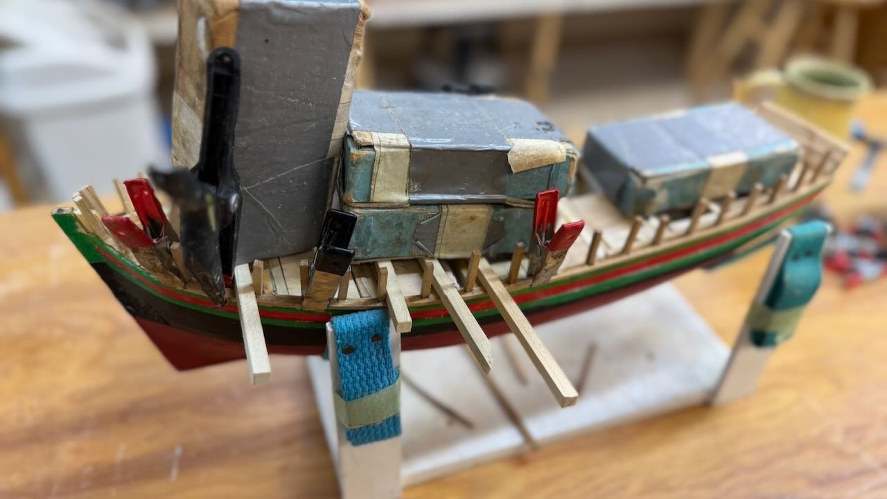
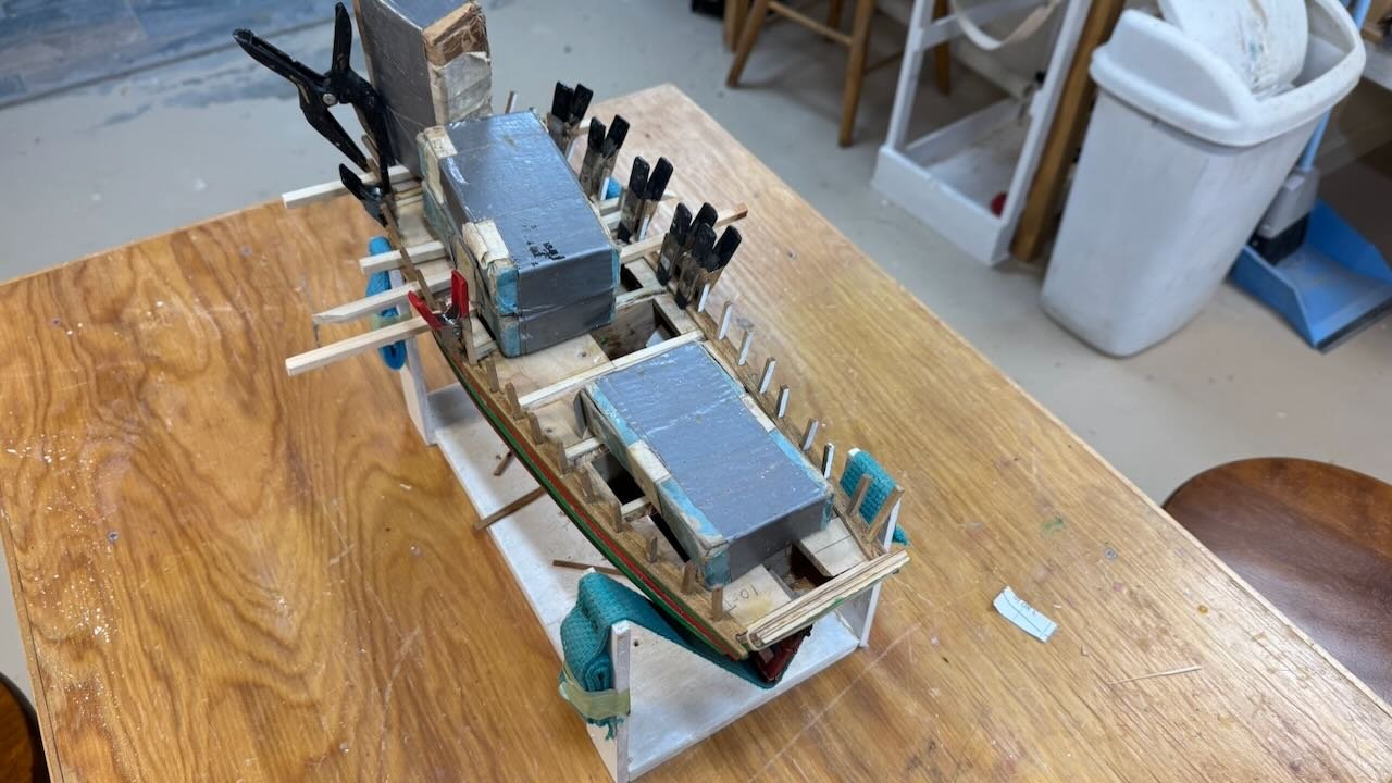
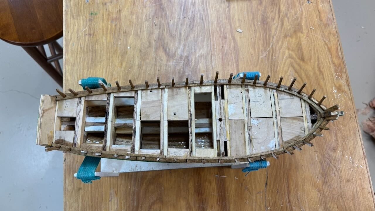
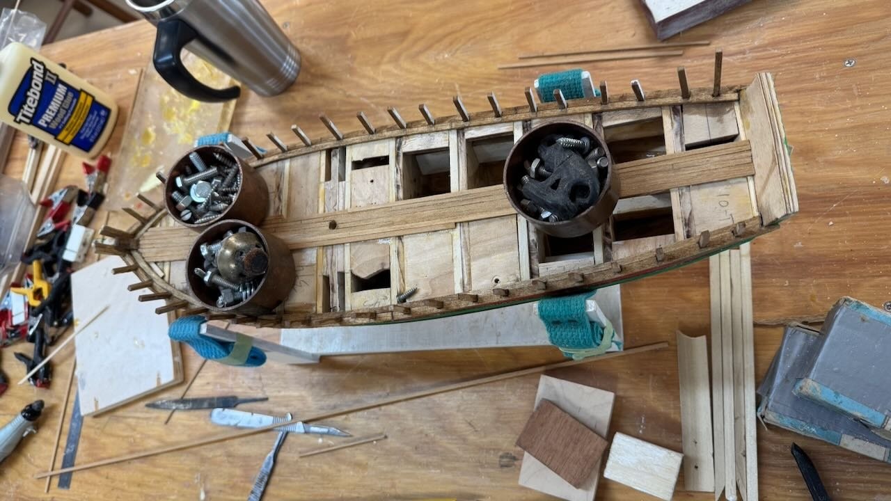
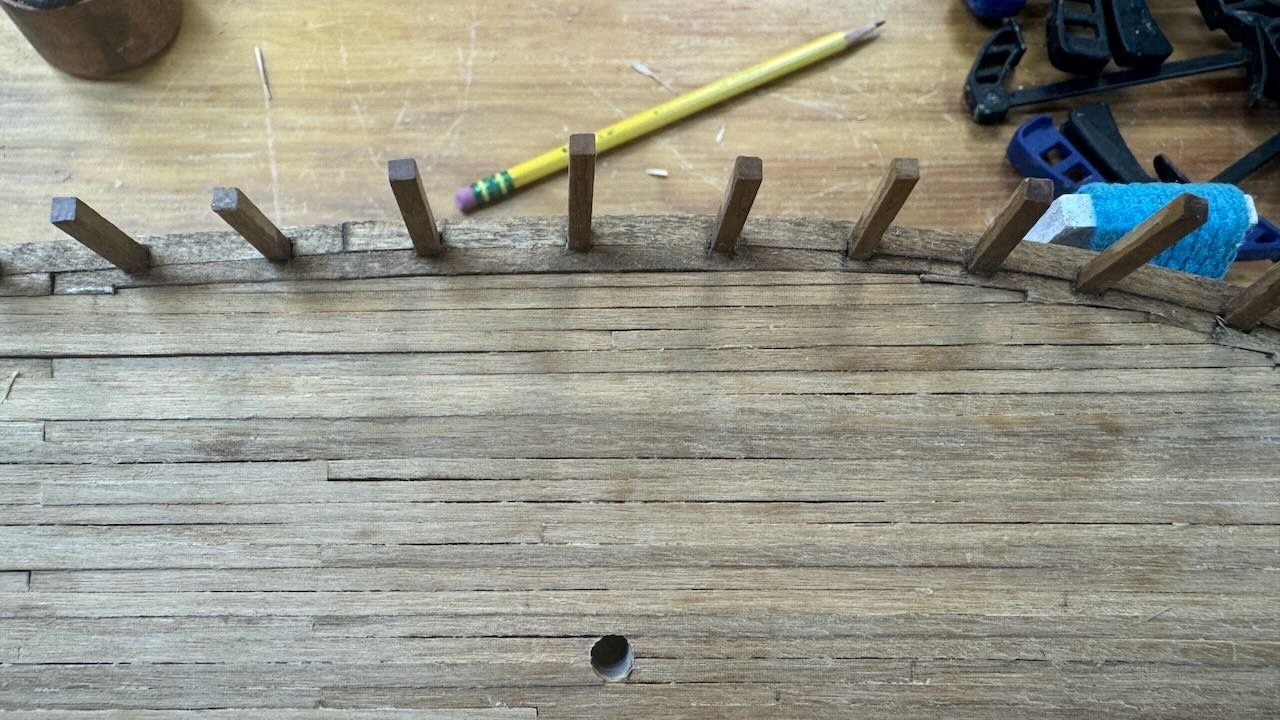
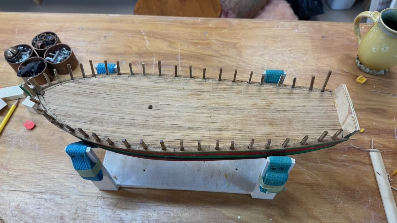
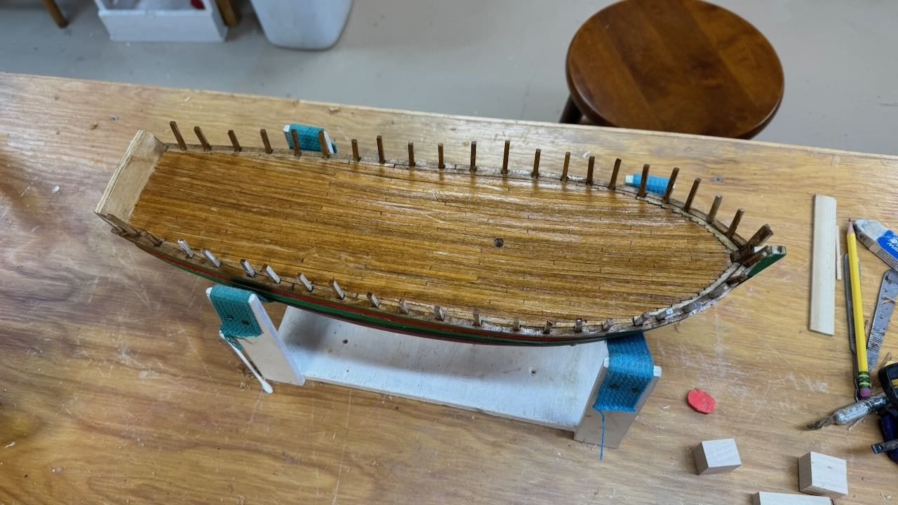
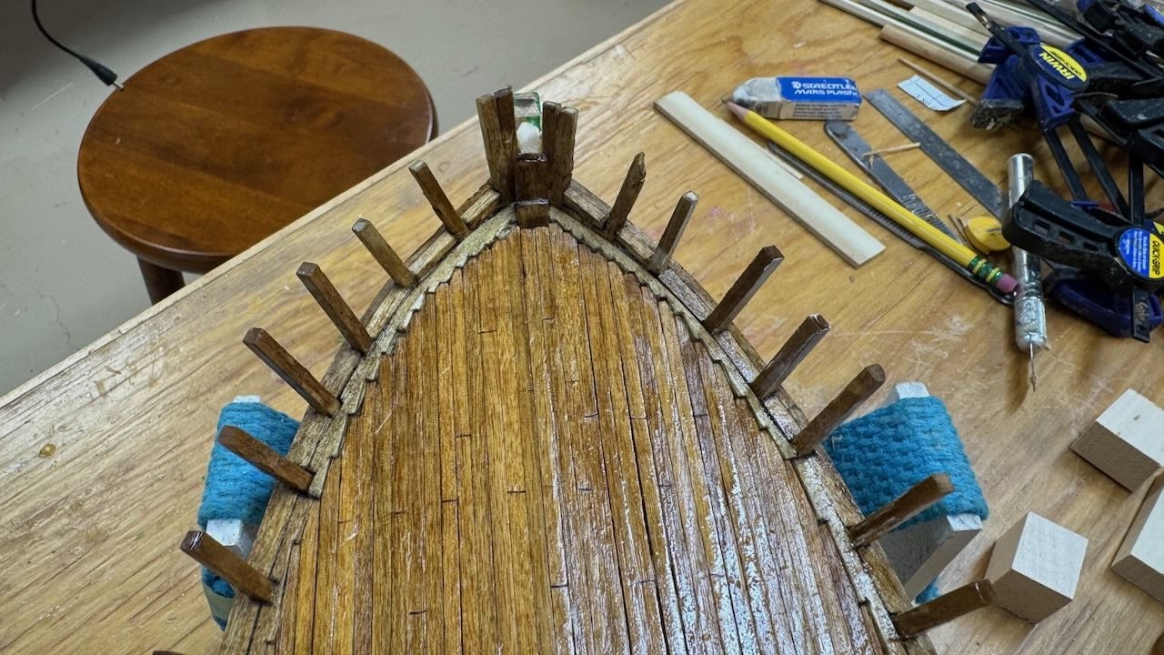
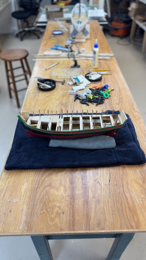
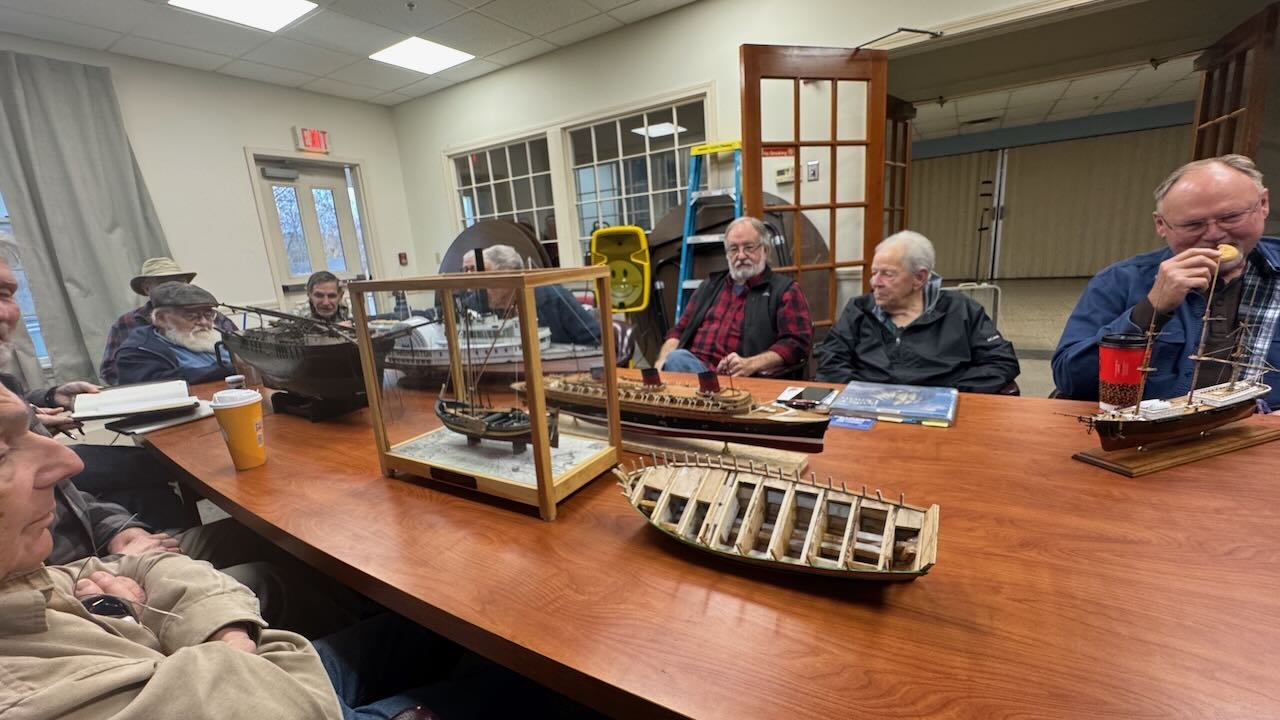
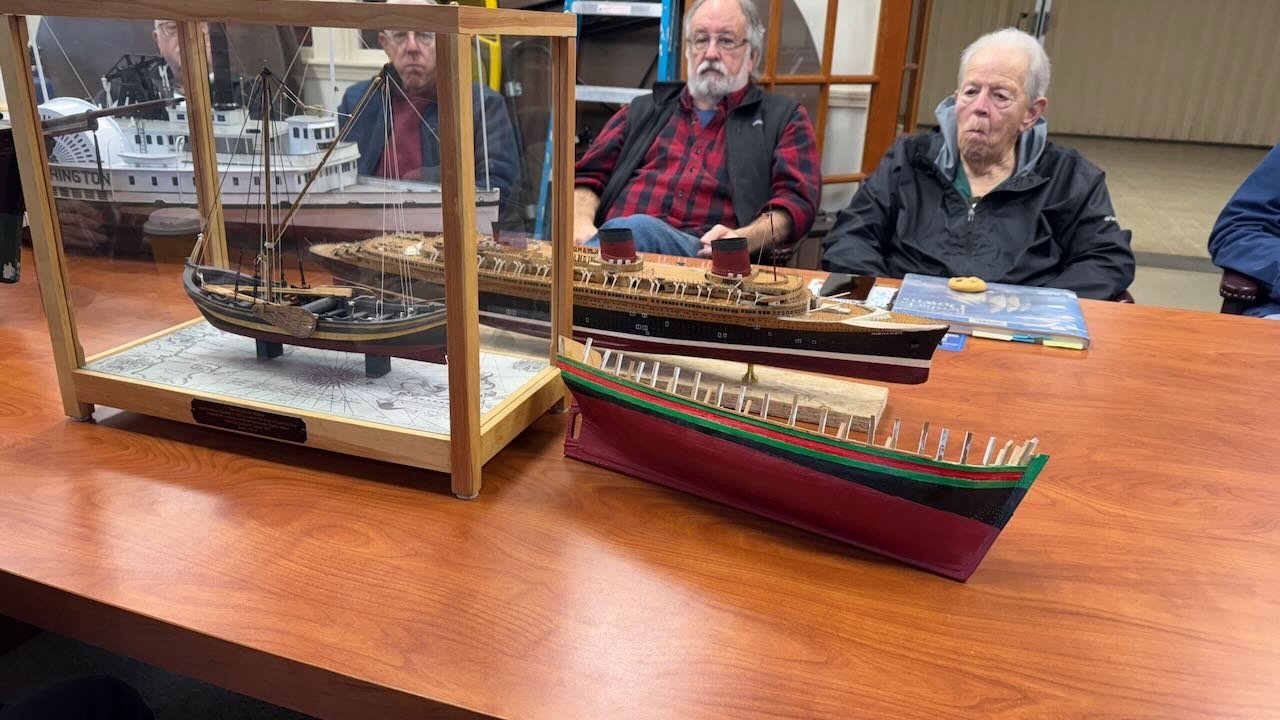
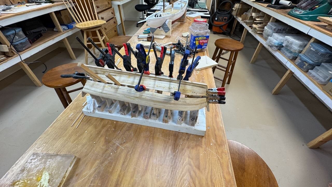
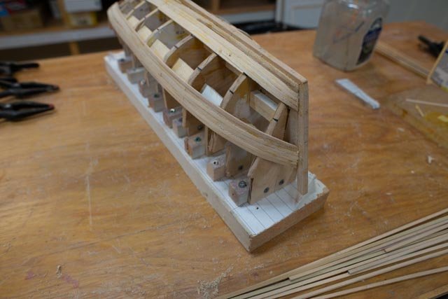
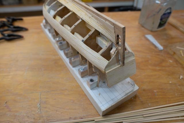
5a starting the prep for the decking This mid review gets us almost halfway to “ready to deck”. I have decided I want to add the decking before the bulwarks because I can then better hold down the fresh planks with the sides open. I hope it all works out. 1-2 these views showing my lay out of deck beams after removal of all the bulkheads. These beams are canted and set right, so I have a little more trimming of the bulkheads to be at or below these beams as we go. In the second images I have brought out a scaled-up deck plan, so I can understand where I need “grounds” or underdeck structure to take connections of equipment etc. 3 this image is to celebrate a full cleaning of the work area. Something needed more often than we admit. My concurrent build, the schooner Elizabeth Howard, is at the other end of the table. 4 Here we see installed under structure to areas of the desk where it is needed. I have focused to get one side done and included the extended frames at this time as well. I typically use up the scraps cut from the bulkhead extensions after removing them. The soft Luan plywood is easy on drilling for pins etc., has nice thickness and is light weight. The mast step is dead center of a blkhead. I used a 1/4 hole and will cut down the 5/16 mast at the deck line. 5-7 These 3 images show the work in the bow. I wanted to have solid cant frames at the bow as I assumed that they would have been in place. When looking at the museum pictures and others’ interpretations, I find unlike our Yankee schooners, these frames are cut off at the deck. Only a few are extended to carry the bulwarks forward to the stem. I would consider that light construction especially for arctic seas. [ not my call]. I cut them down to just above the deck. 8 shows the pre-stained shear plank [ outer half] installed most of the way forward. I will work on the tight bow curve in the next update. 9-10. we had our monthly guild meeting and off I went. The second images is to highlight the privilege I had to set my model next to a beauty. The Mayflower shallop recently on the cover of NRJ is in the case. She was built by one of our members, who also is member and active at Newburyport, Ma. I took the picture saying that I hoped sitting there for an hour or so my model could improve. One of life’s little rewards is to occasionally be next to a master of his trade. Cheers

- 55 replies
-
- 8
-
-

-
- Northwest passage
- Norway.
- (and 2 more)
-
Dear Druxey Thank you for dropping in. I recall sitting at a table with you at one of the last summer NRJ conferences in New Bedford I believe, where you showed us how you used simple hand tools to make a perfect mast. It was inspiring. I have to admit still well over my pay grade. When I get to it the mast on this little vessel has some twists. it is absolutely straight up per the drawings. The gaff is huge. In the Amundsen diary, the gaff broke three times. anyway...thanks. I have replaced the damaged plank.
- 55 replies
-
- 3
-
-
- Northwest passage
- Norway.
- (and 2 more)
-
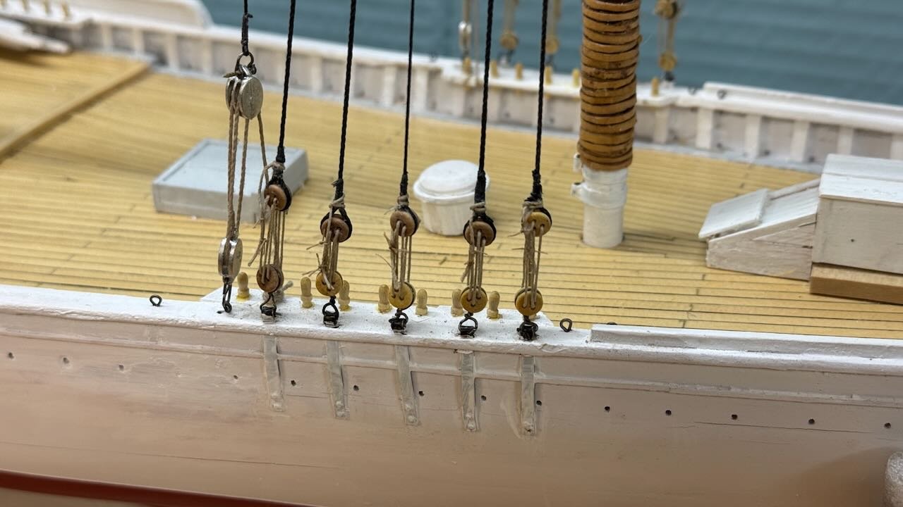
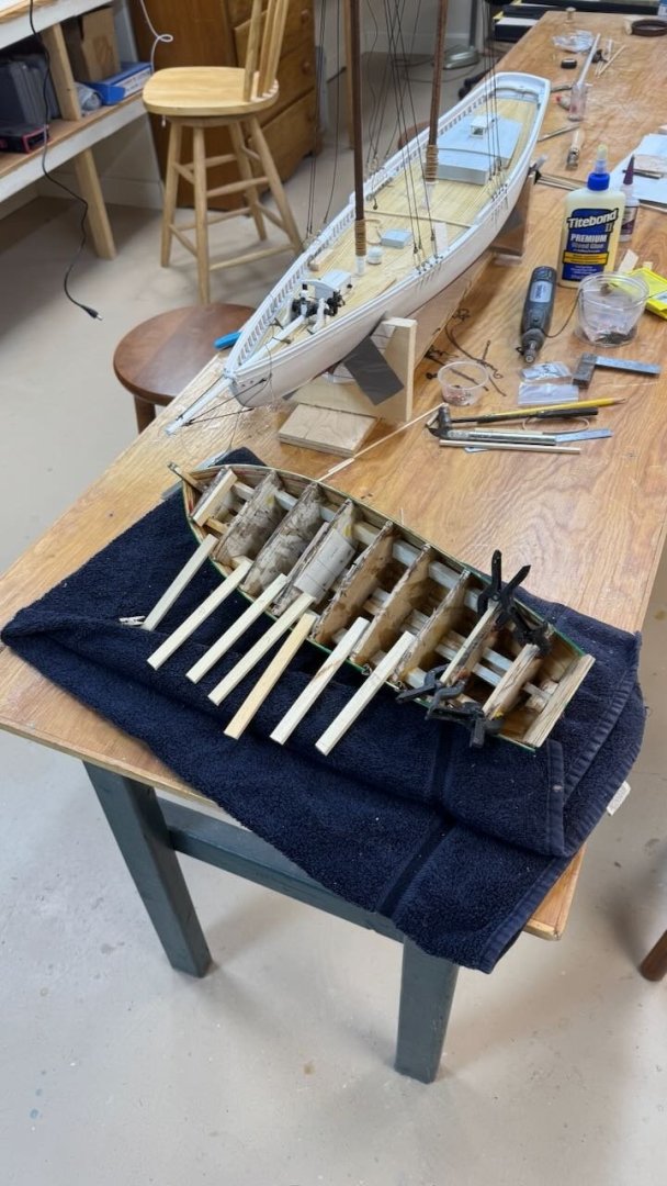
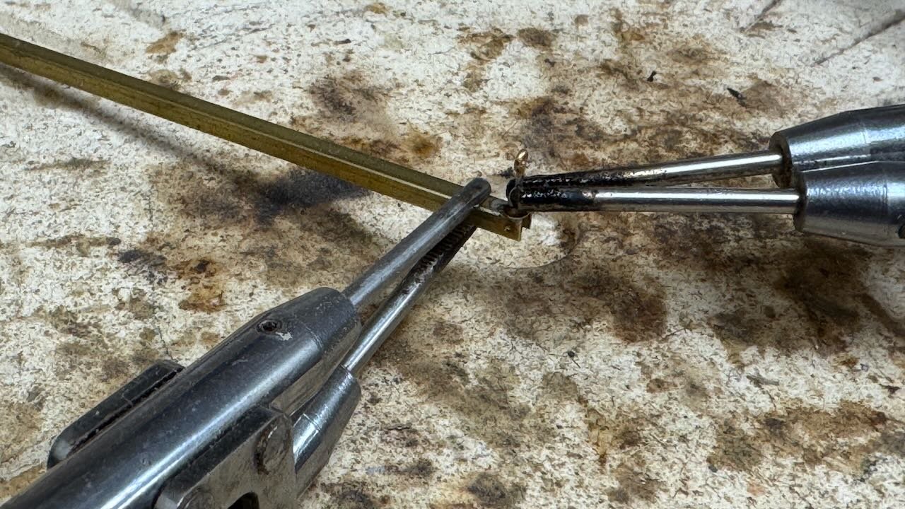
13a deck work and standing rigging moving along As I now divide my time between this build and the 1872 Norwegian ship Gjoa, things are not so fast. It is fun though, as Gjoa is in the hull stage as this build is into deck furniture and starting the rigging. This is a partial update. For most of my guidance I refer to the age-old favorite book o fishing schooners by Howard Chapelle. Several similar scale schooners in the past and the detail I learned building a bigger scale bluenose several years ago. One difference from Bluenose is, from the photos of Elizabeth, lashed dead eyes were used instead of turnbuckles. Perhaps the 5 years between 1916 and 1921 made the difference. I am therefore using lashed bullseyes for many of the fixed stays that surely would have needed adjustment. To work 1-3 these images show my low-tech approach to building the sliding goose neck for the jumbo boom. I took a brass channel drilled a hole on top. Then I set a tiny rivet upside down and put a cut off brass eye with system through the rivet and the hole in the channel and soldered it up. I then soldered a clevis on the end of a rod to sink into the fore end of the jumbo boom. I also added some handles to control the winch [ imagined anyway] and some chain. I am not proud of the mechanism but is represents that something would have been there. 4-6 these images show progress making up the hardware and stringing the running rigging aloft. It is all left untied for now. When it is all in place I will have some extra hands here over the next holiday and we’ll square it all up, tighten and then lash all. 7 This image shows from the bow, the bowsprit and fore stay rigging is taking shape as well. I even put in all the belying pins


-
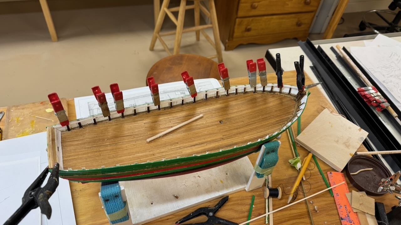
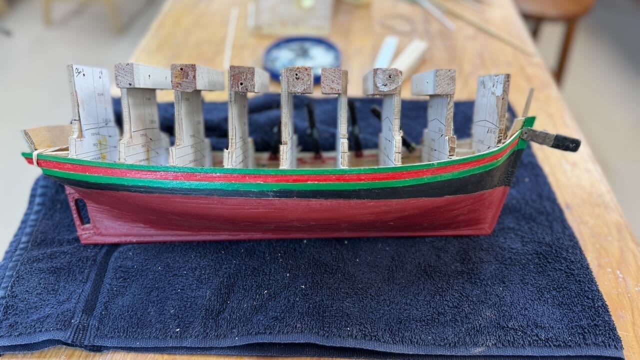
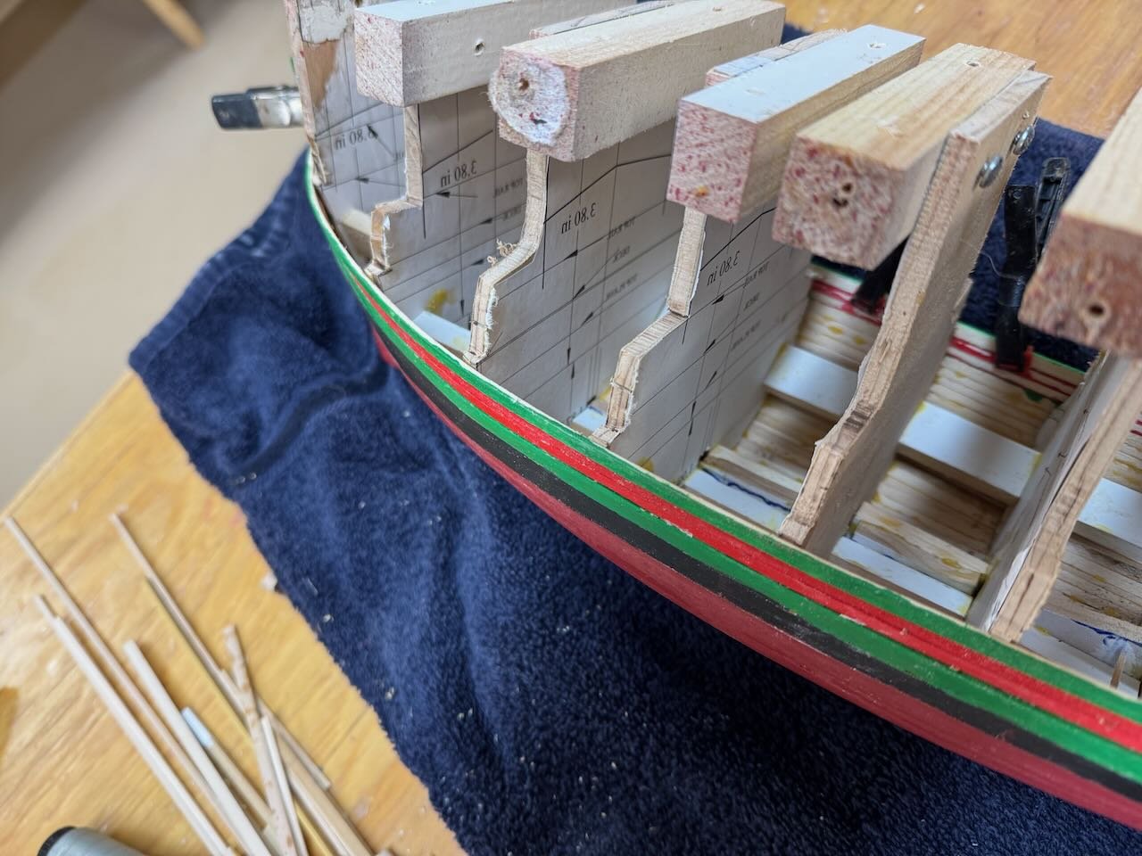
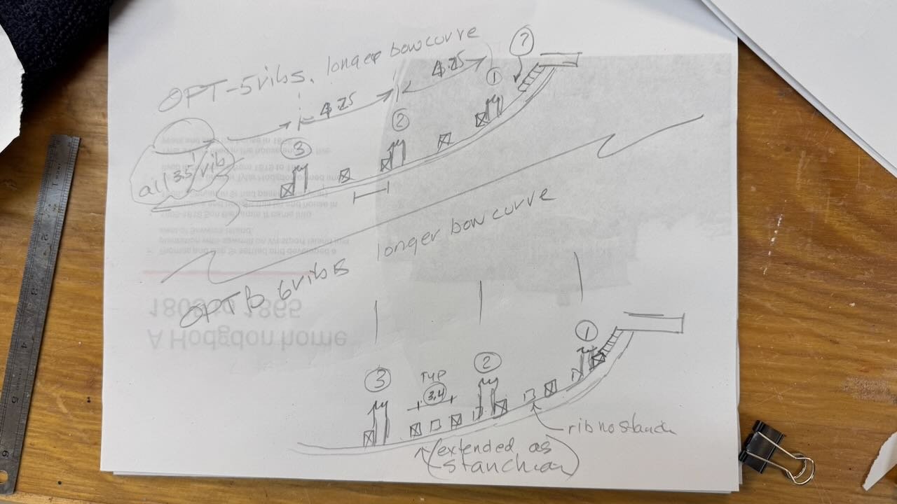
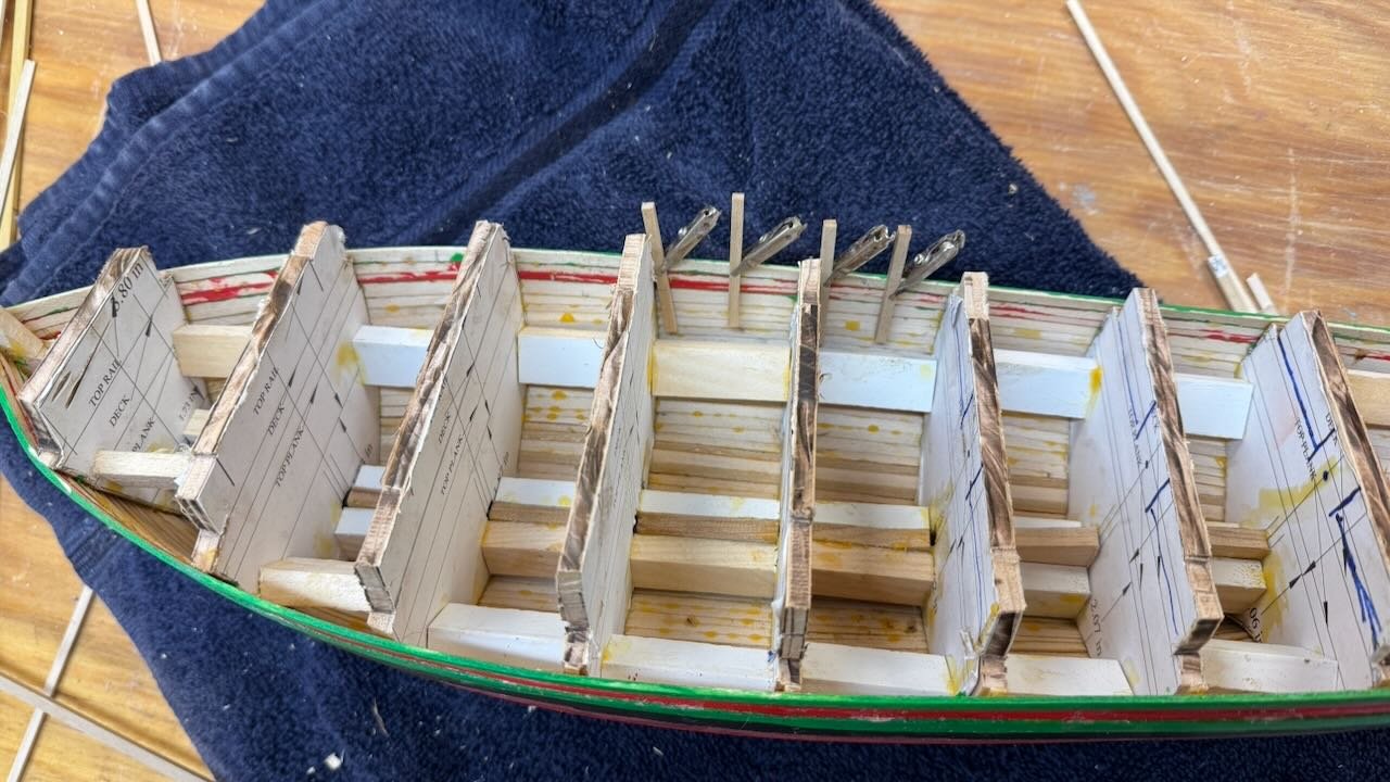
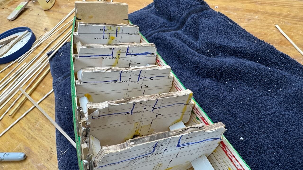
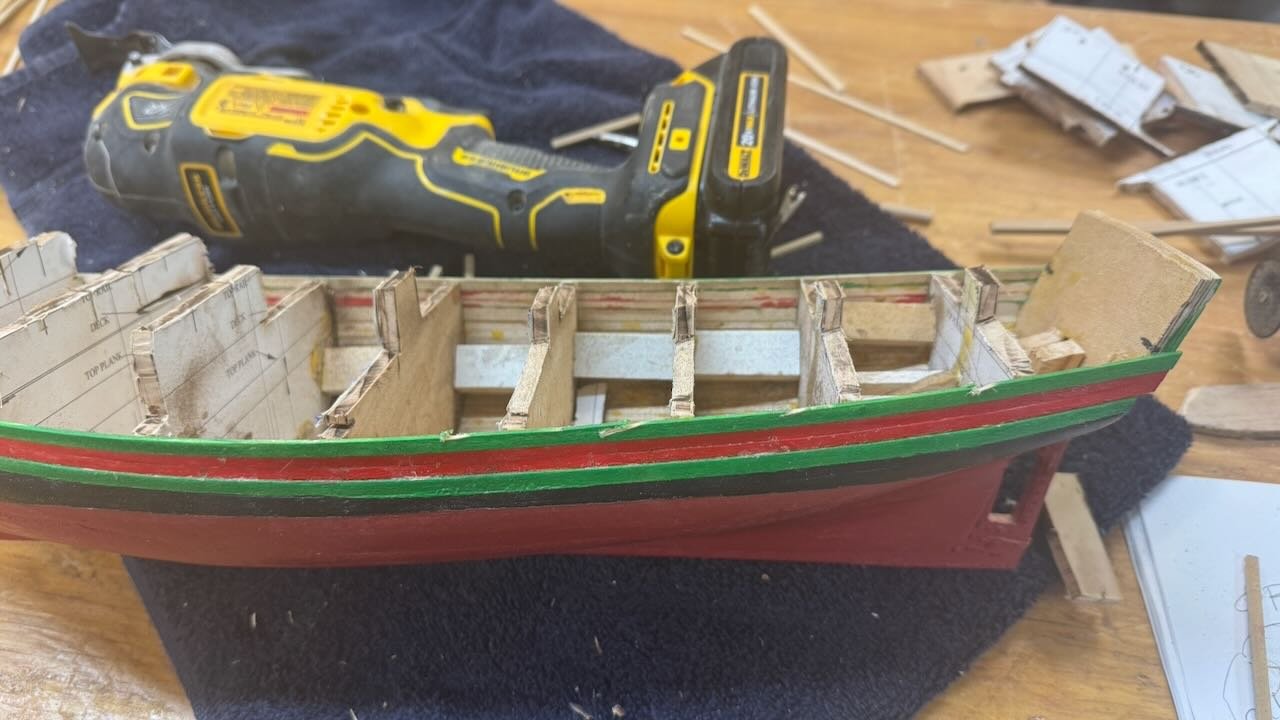
4b topside planking done This update takes us through the four topside strakes below the deck and taking the hull off the jig. Then a quick look at possible ways forward. That means’, what’s next? 1-2 here we see the screws were undone holding the bulkhead blocking to the building board. Then the closeup shows the first cut back of the bulkhead at the deck level. 3-4 show the first cut down of the bulkheads to the top rail level. What’s next to me is to figure out the extended frames acting as bulwark stanchions. I am going by the theory that every other frame would have been extended. I stretched a ¼ inch scale tape and found most bulkheads are 7 feet apart in scale. That would mean mid frames to be 3.5 feet or 42 inch on center. Half again would make frames at 21 inch centers, and that seems reasonable. The bow curve increases the distance between bulkhead 1 to 3 by 2 feet [ in scale]. 5. this hand drawn sketch shows my thought process. To continue the logic of the hull framing foreword of bulkhead 3 would continue with four stanchions [ 8 frames]. The spacing would grow however to 4.24 feet or 51 inches. I think that would be wrong. Therefore, I will use option 2 and add another stanchion [ or ttw frames ] in this area to keep more reasonable spacing. All of this thought is seat of my pants but I want to have at least thought about it. 6 this view shows I have milled down some Costello strips to act as extended frames. I prefer their super smooth finish properties over a softer wood. 7 This view shows the second cut down do the bulkheads. I am cautious to remove all and for now am keeping the center section up to the rail line. I think that is waste of time for two reasons, so will likely change next week after more thought. This hull bulwarks is made up of 4 parallel strakes so probably no reason. If I make all the stanchions too high, they can get sanded back. Thus, having set them from the lines is not needed. I have learned the hard way that to build the bulwarks and then try to sand the bulkheads to use as deck framing is between awkward to impossible. So Likely I will first sand the bulk heads down, add a few thin beams to control the canter of the deck first and add tall stanchions second. 8. There as a oops. I foolishly thought to take my utility tool and cut smoother lines. The sideways vibration of the utility tool dug into my top strake. Oops. One step back I guess. 9. I followed Phil's advise and brushed in a light coat of resin to make the inside of the planking wicked strong. Also I needed to remove the inside blocking at the transom that would have interfered with the decking.

- 55 replies
-
- 8
-
-
- Northwest passage
- Norway.
- (and 2 more)
-
Phil To seal the insides.......That sounds like great advice. Back when I started all this modeling, my hulls were for Radio Control sailing and both inside and outside were epoxied. Those hulls will last a long time..😀 I have never done that on my static hulls, but it makes a lot of sense to at least seal them, and I will do it. On this build , especially when the top strakes I am doing are so thin, a thin epoxy makes good sense. thanks for the advice Jon
-
Julie thanks again for jumping in. I think working on the color is fun more than anything. Most of out New England builds are a bit boring. That said I fear "fiesta Green" and " real Red" respect painting that was apparently important to the crew. In Amundsen's diary he mentioned how before leaving after wintering, not only was the hull cleaned out and scrubbed, but they carried paint with them and touched it all up. It's too bad their photos are all black and white. cheers
- 55 replies
-
- 2
-
-
- Northwest passage
- Norway.
- (and 2 more)
-
Harvey thanks for dropping in. I have enjoyed your build as i have started this one and will drop back many times. Your study and work on deck and with the rigging looks great. I will highlight your source when i get to that stage. I am still not sure what i will do for setting up the scene. Perhaps when snow gets here it will come to me. cheers
- 55 replies
-
- 1
-
-
- Northwest passage
- Norway.
- (and 2 more)
-
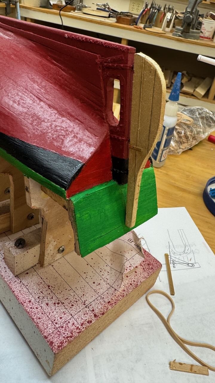
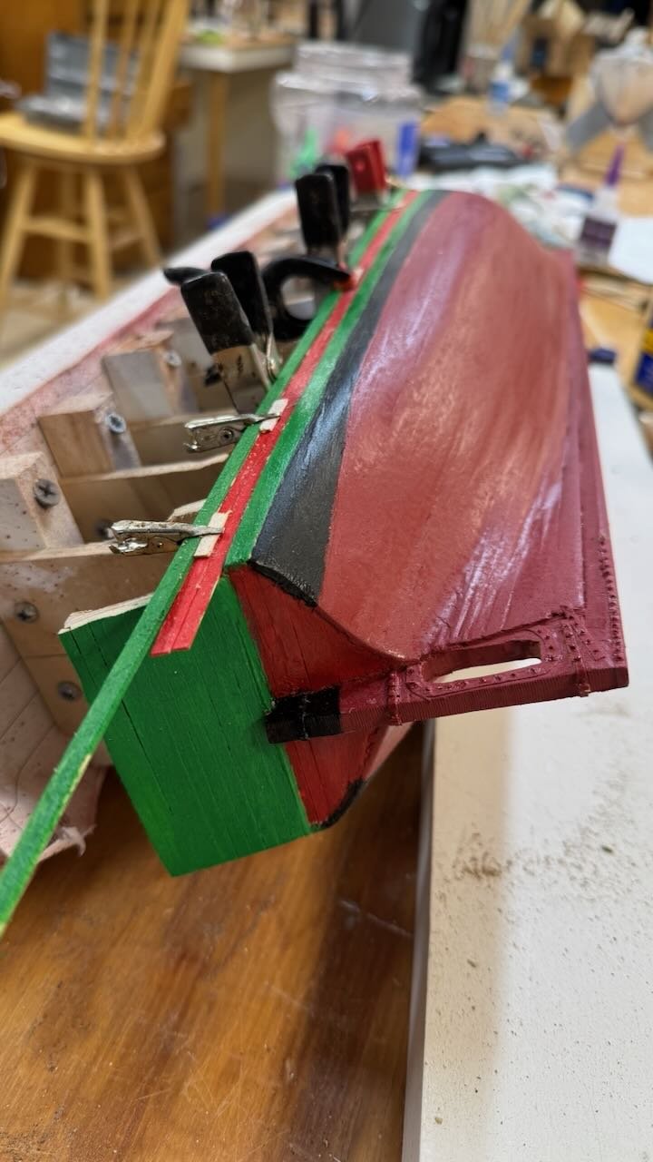
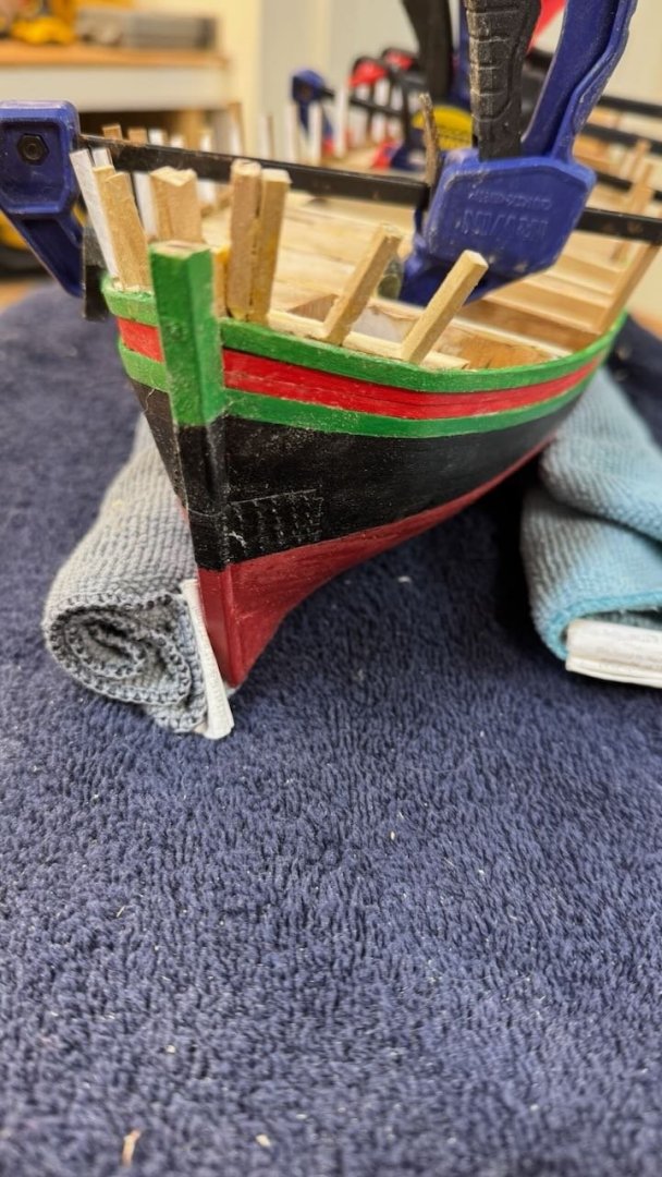
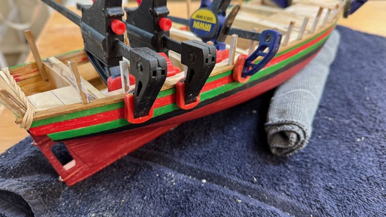
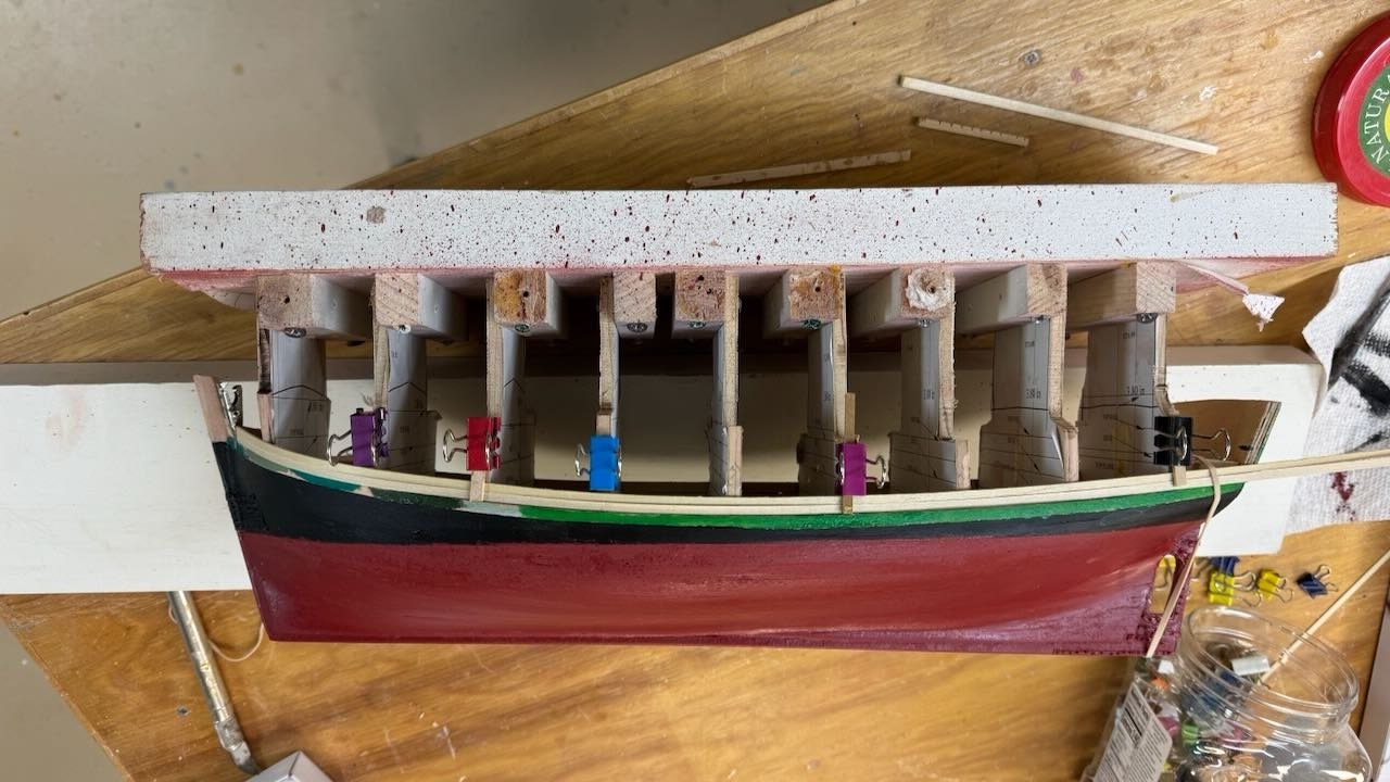
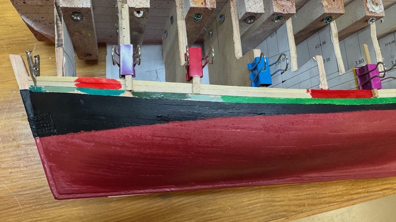
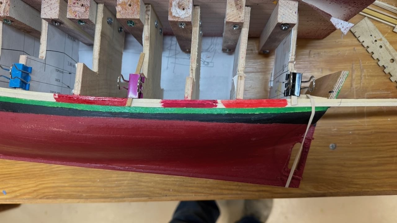
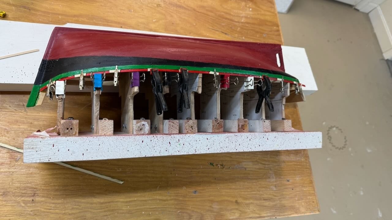
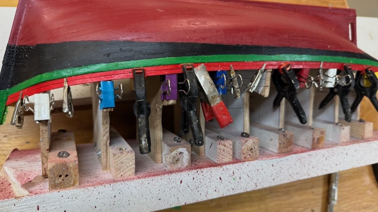
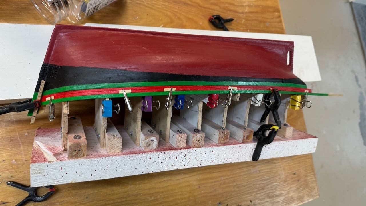
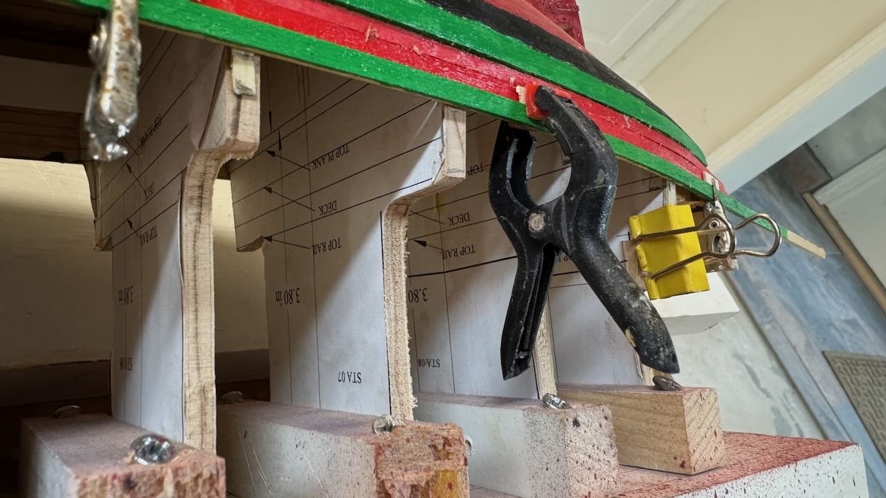
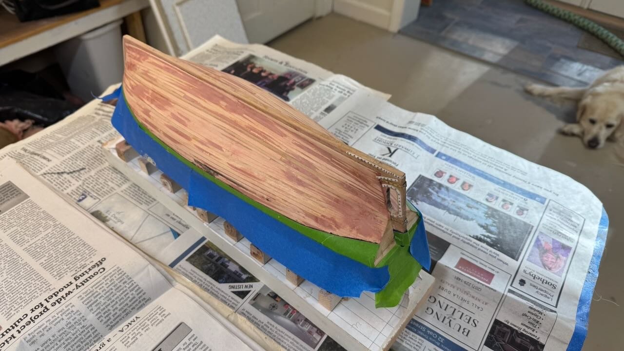
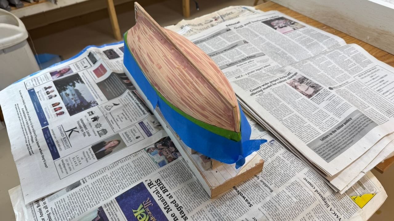
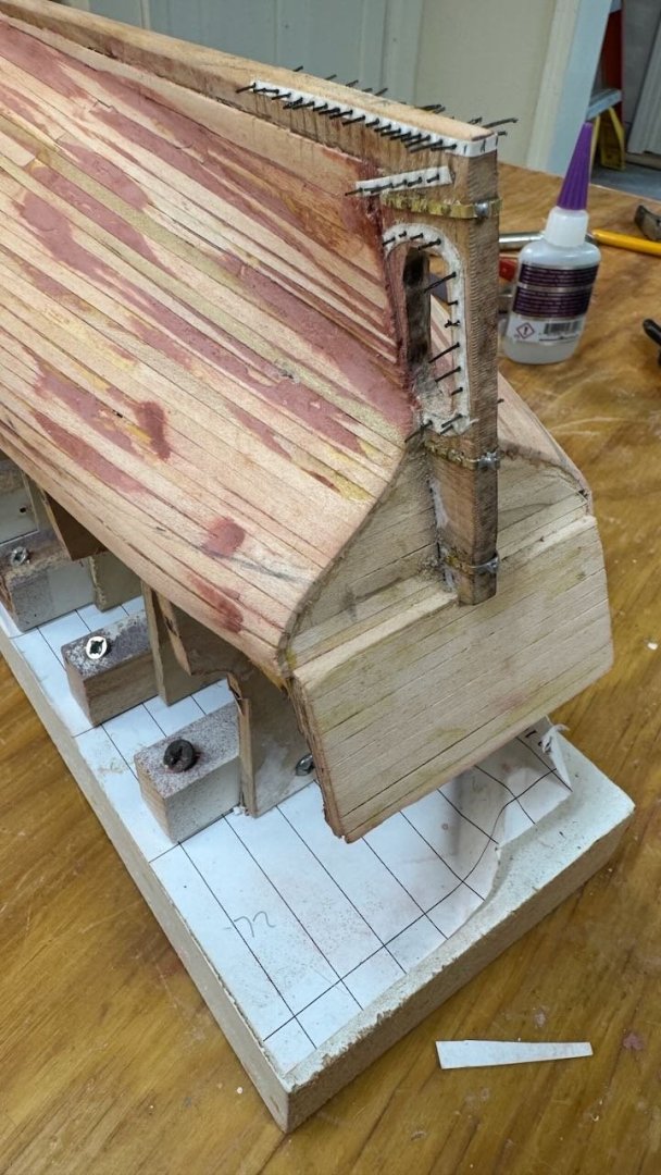
4 topside planking now started This step is turning out to be a bit complicated. It is easier to show than just to go forward with words. Here is my trial [ and probable error] attempt to do this upper planking. 1 In this museum web photo we see green in sunlight. It is the color I am after. 2 In this image I dry fit the two thin stakes to plan clamping 3-4 here I try different greens and reds to capture the spirit of Norwegian painting. My shop work table overhead light is day light so a a good idea….I hope. 5 A parallel task is to build the rudder and its pintels. 6-7. first then, and then the second strakes set in place. 8-10 dry fitting the top green stake and marking the bulkhead for removal at the deck level. 11-12 the bulkhead has been cut away above the deck line and the top green strake glued in place, Next up is the port side . I will then plan to remove the jig to get ready for the deck. The shaer plank protrudes through the planking. All fun. I hope it works


- 55 replies
-
- 7
-
-
- Northwest passage
- Norway.
- (and 2 more)
-
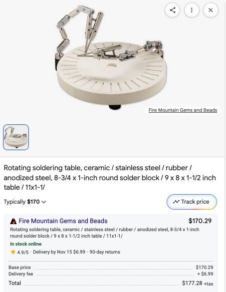
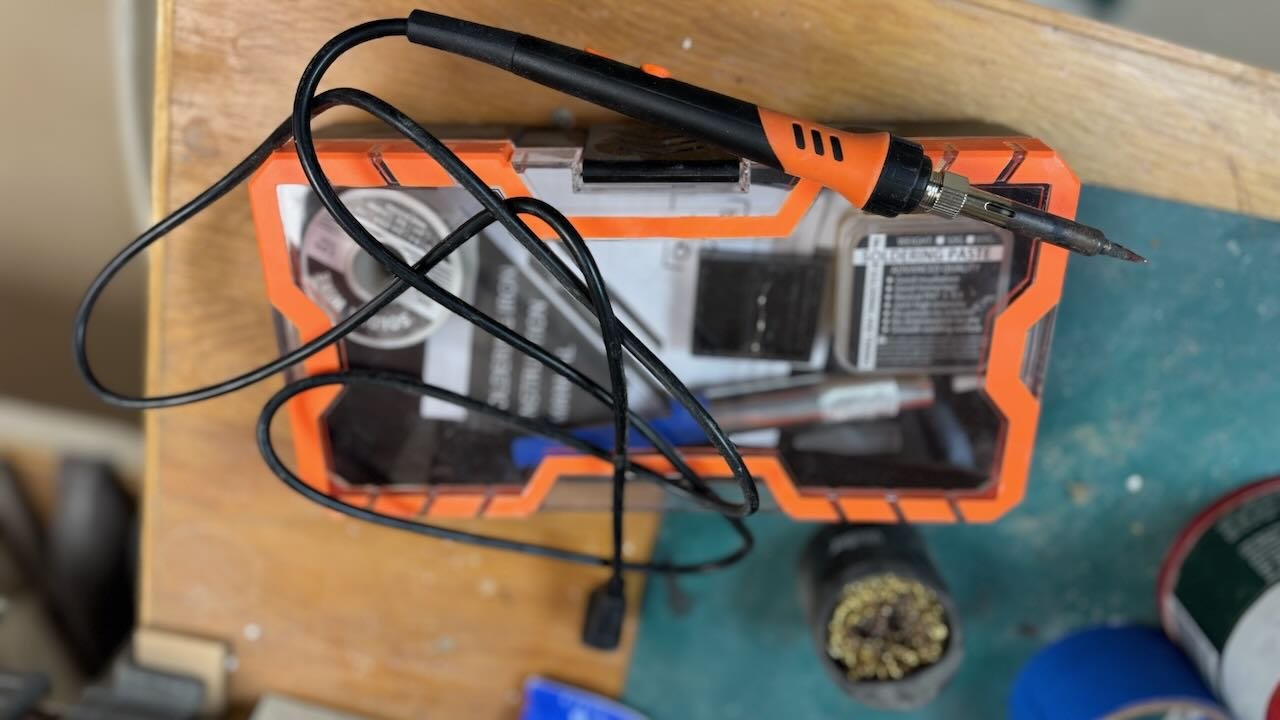
Phil What I use is one of many soldering tables I found on line several years back. I think I got mine from Rio Grande, but I'm not sure. Here is photo of one on line that looks similar I see several others and some a bit cheaper. I am a total amature when it comes to soldering or any metal work. That is one reason that I record my learning process. One major issue in these small pieces is holding them steady. These very rugged clamps are great for what I try to do making little fittings. The soldering iron I bought online after watching a friend's blog from nearby in Maine. When I saw it, I bought it. I had found many of the electrical ones I tried just didn't get it and was using butane torch on everything.....too much for this size. ...this one does it quickly, so I am doing a little more each build.
-
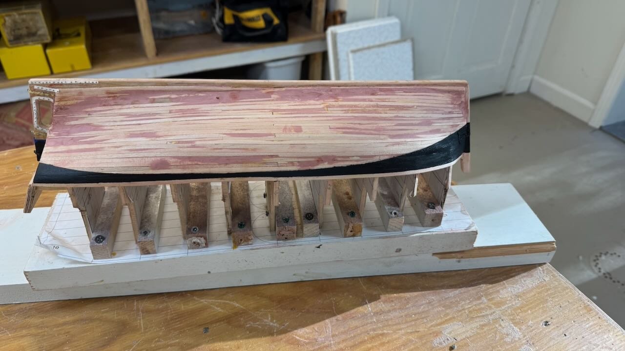
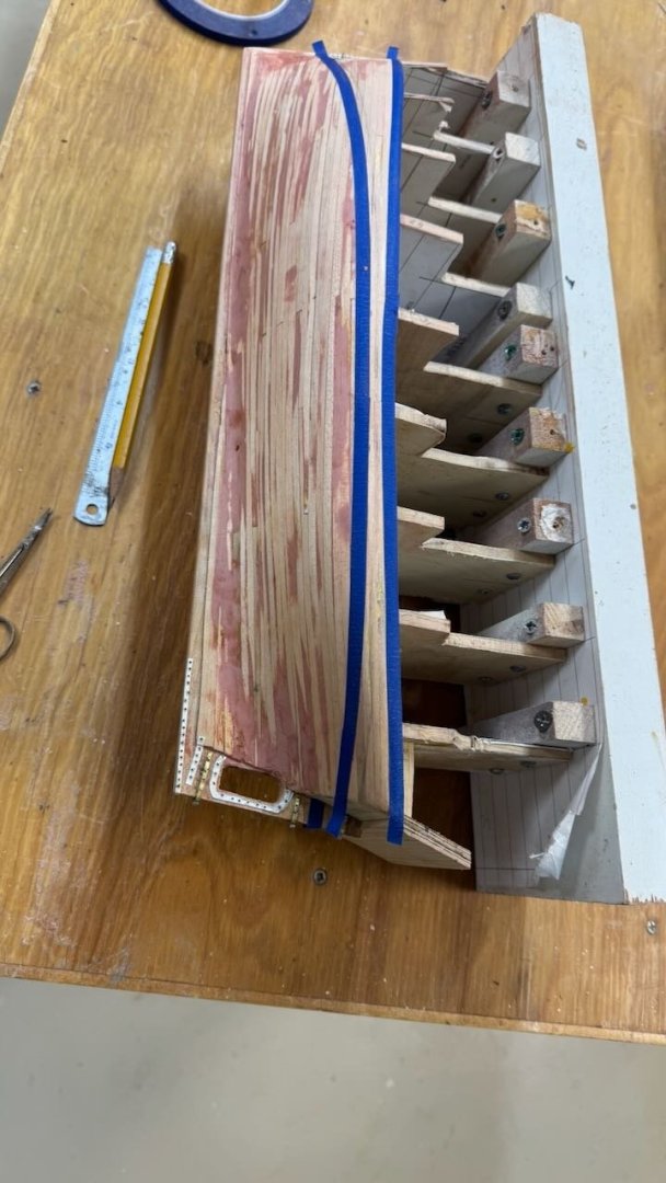
3b painting prep and firs paint This update shows steps to get the lower hull ready and painted so I can removed if from the jig. views 7-8 show results of glazing putty repairs and marking of the waterline. the hull is wet as I just damp rubbed it to get off all the dust. views 9-11 show my low tech means to build the gudgeons in brass and the plates and bolt heads using mylar fishing line views 12-13 show taping out the black section above the water line and afyer painting it. views 14-15 show taping out to allow rattle can spray of heritage red for the bottom and "backside". I mentioned earlier that I am trying to build this model without buying new stuff. As anyone knows, 12 years into retirement, our home collection of parts, wood etc. is ridiculous. The problem came up when I started to spray red with a can that has sat for more than a year, it wasn't pretty. We'll see in the next post how all came out. cheers


- 55 replies
-
- 9
-
-
- Northwest passage
- Norway.
- (and 2 more)
-
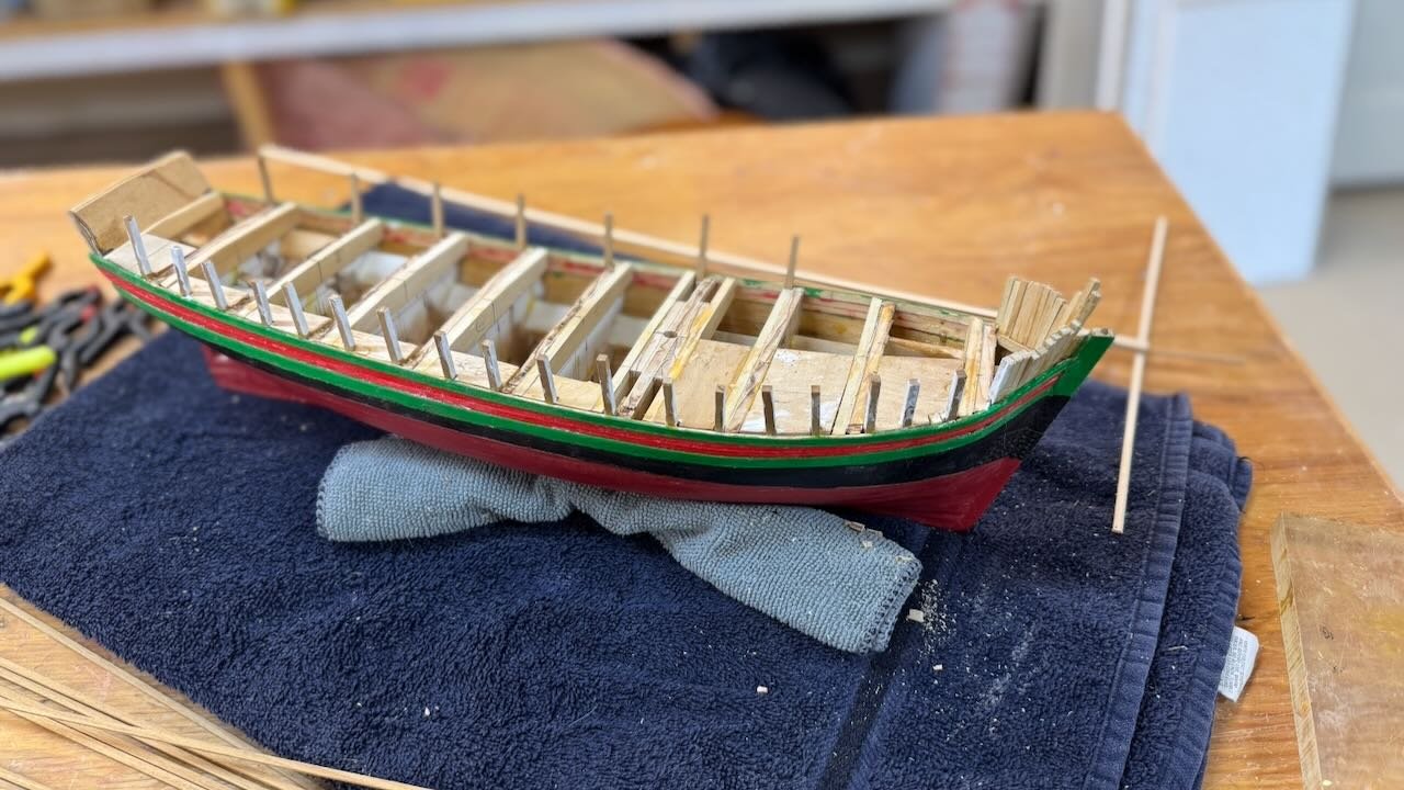
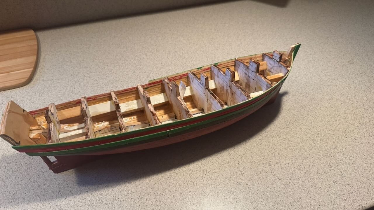
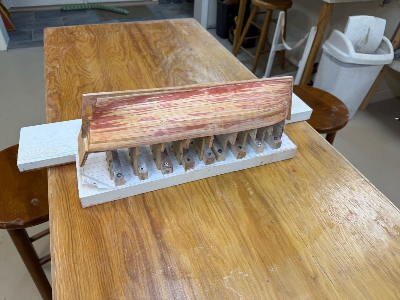
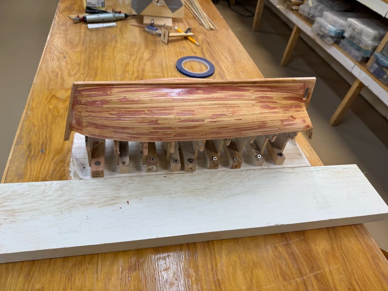
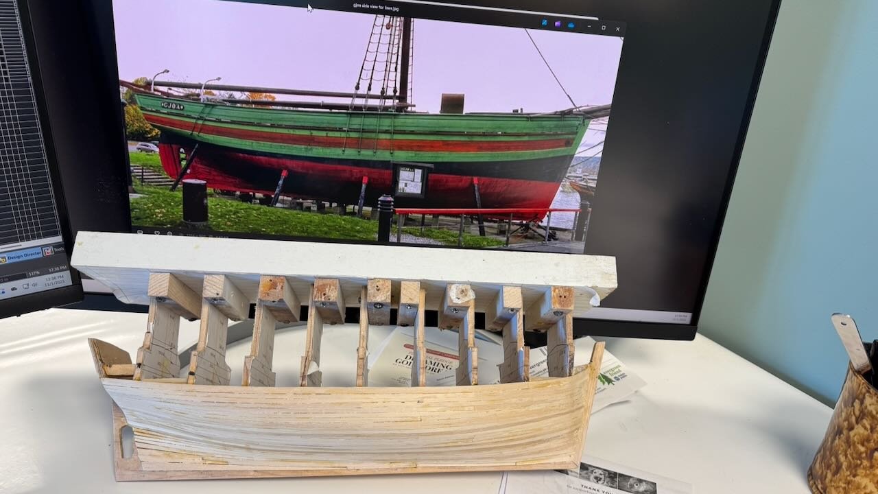
3 lower planks are on …what’s next Fumbling along I got the rest of the planks on for the lower section of the hull. 1 this view shows the joy when we get from clamps to wedges….I think that’s like getting to the red zone in an NFL Sunday. 2-5 The next four images are two sides presanding. I show the upside-down images as I will be changing away for the base board, needed up to this point, for the upper hull work as I have learned the hard way to cut out the building temporary bulkheads now. They need to be out of the way before trying to match planking and the deck line. Before that however we go to a challenge of this build. Painting. I like building Maine boats, One reason is they are typical either black of white. Gjoa is quite fancy and I need to stretch my skills accordingly. 6 The next image shows the hull in front of a Gjoa museum internet photo showing a nice detail of how to both planks and paint the upper hull. In the image below the top stake installed today will be green. when I go upward I will use two thinner strakes for the red then one thick green. So I am off to the sanding and pre-paint prep to get the waterline on using the level benefit of the current build board before I remove it. Cheers
- 55 replies
-
- 2
-
-
- Northwest passage
- Norway.
- (and 2 more)
-
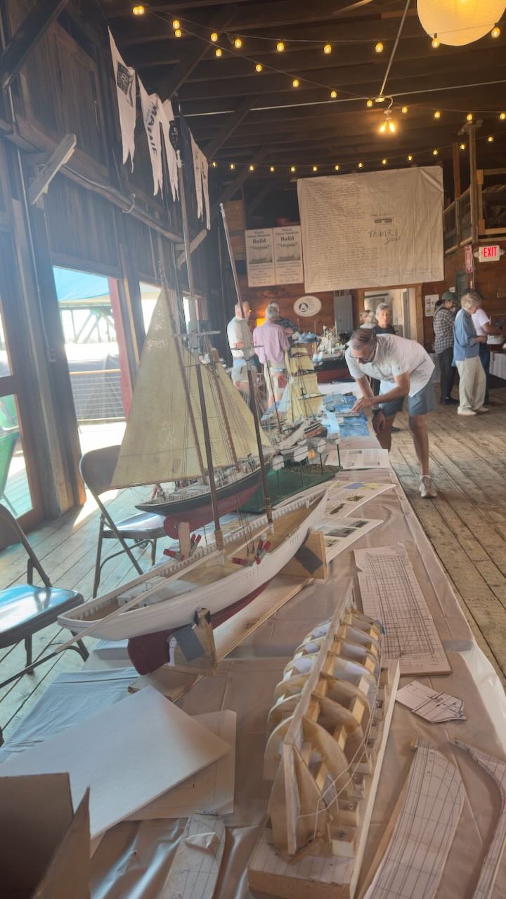
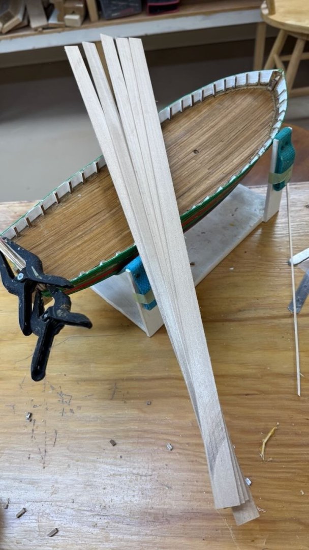
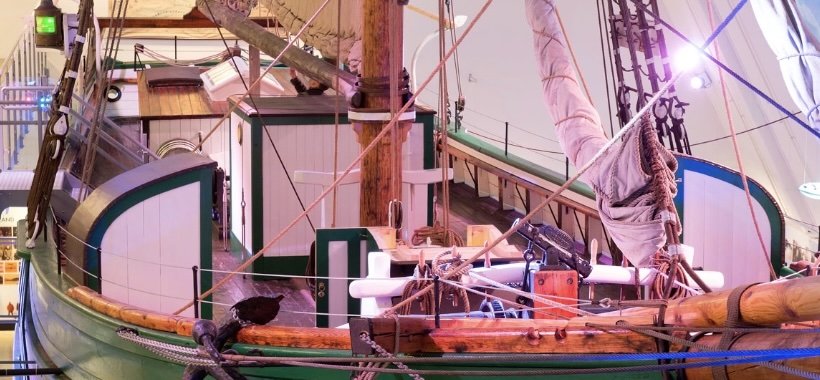
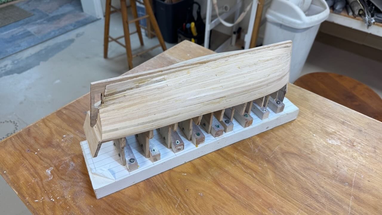
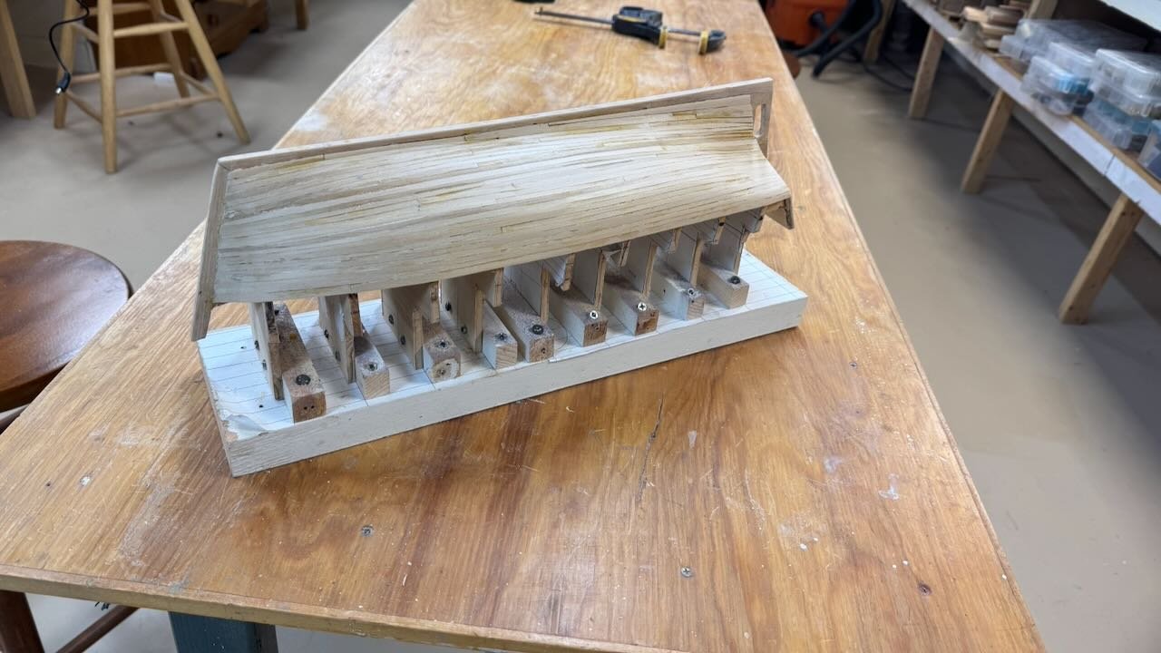
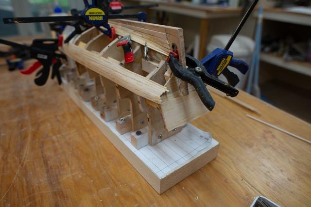
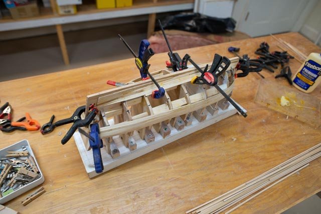
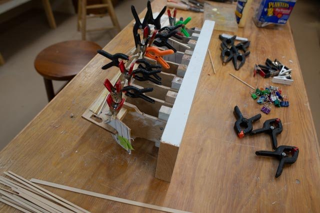
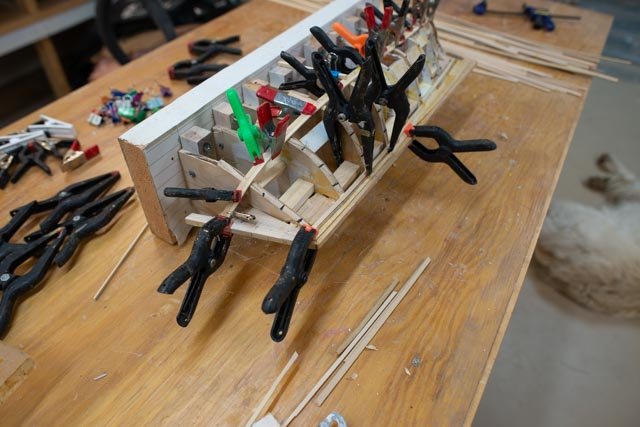
3 partway through the planks We had a little excitement last month when our annual Northeast Shipmodelers Guild show took place in Bath Me. We went this year to the shed associated with Maine's First ship. That is the reconstructed replica of the 1607 Pinnace built here,named Virginia, known to the be first European vessel built in America. Here is their website internet image of her sailing from the shed Here is an image of Gjoa sitting with other of my collection at the show inside the shed. The idea was for all of us to bring models being worked on. The audience was lots of fun, some came for the models and others were waiting to go sail on Virgina. Over the past several weeks I dove into the reading of Amundsen’s diaries of the venture across the top of Canada. Wow. What incredible people and how, according to Amundsen they all got along so well. Lots of fun sailing tales too. The gaff seemed to break several times, and the lack of wood was a big impact. During their third winter they were on a beach loaded with driftwood and the tried to replace it....more on that later. Progress The next 7 images are the familiar porcupine type images of early planking and all the finagling we do to fit clamps. Here are two images while at a breathing point, when the first two bands are done and planning the tough center ones commences. Since this is a painted hull, I am milling a few types of scrap wood. most of the planking is cut down bass wood, but a few maple planks are in the stock.


- 55 replies
-
- 4
-
-
- Northwest passage
- Norway.
- (and 2 more)
-
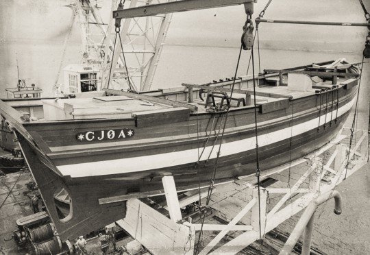
Dear Sheepsail. thanks for your interest. I think San Francisco has lost a treasure but the whole story of her return to Norway was fun. And now the Maud recovery from Arctic Canada..... the beat goes on. cheers
- 55 replies
-
- 1
-
-
- Northwest passage
- Norway.
- (and 2 more)
-
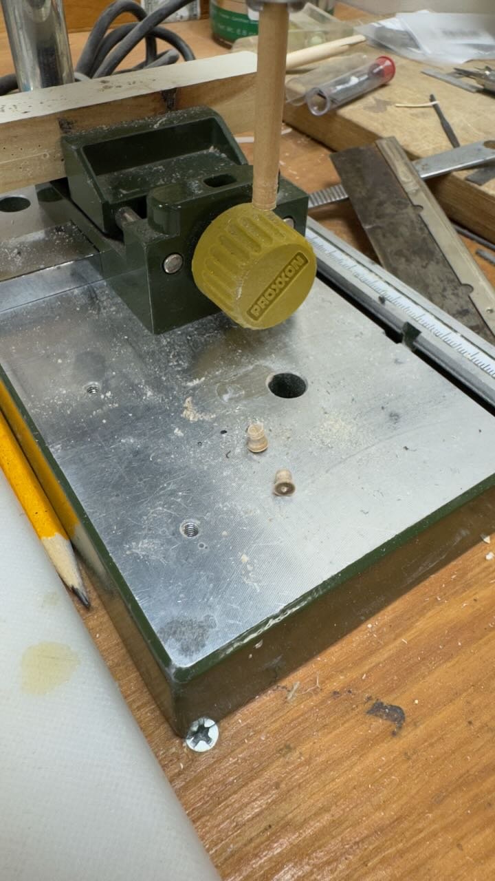
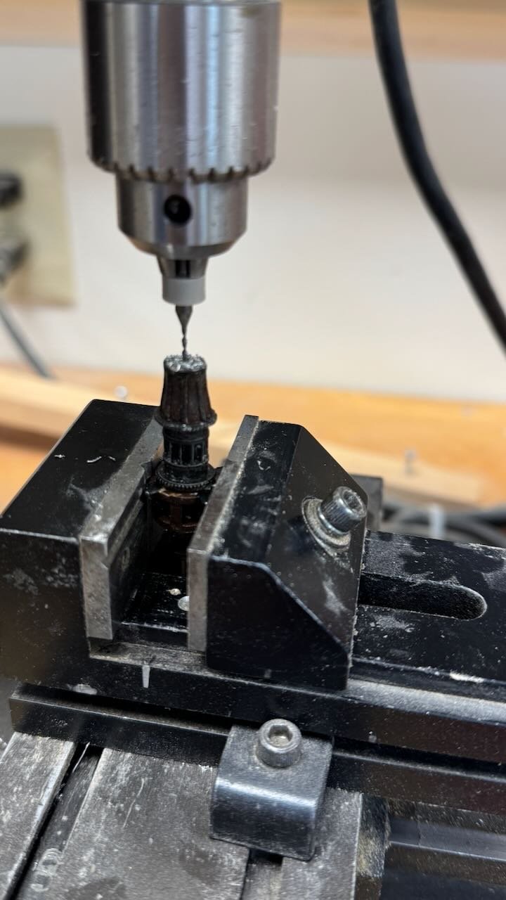
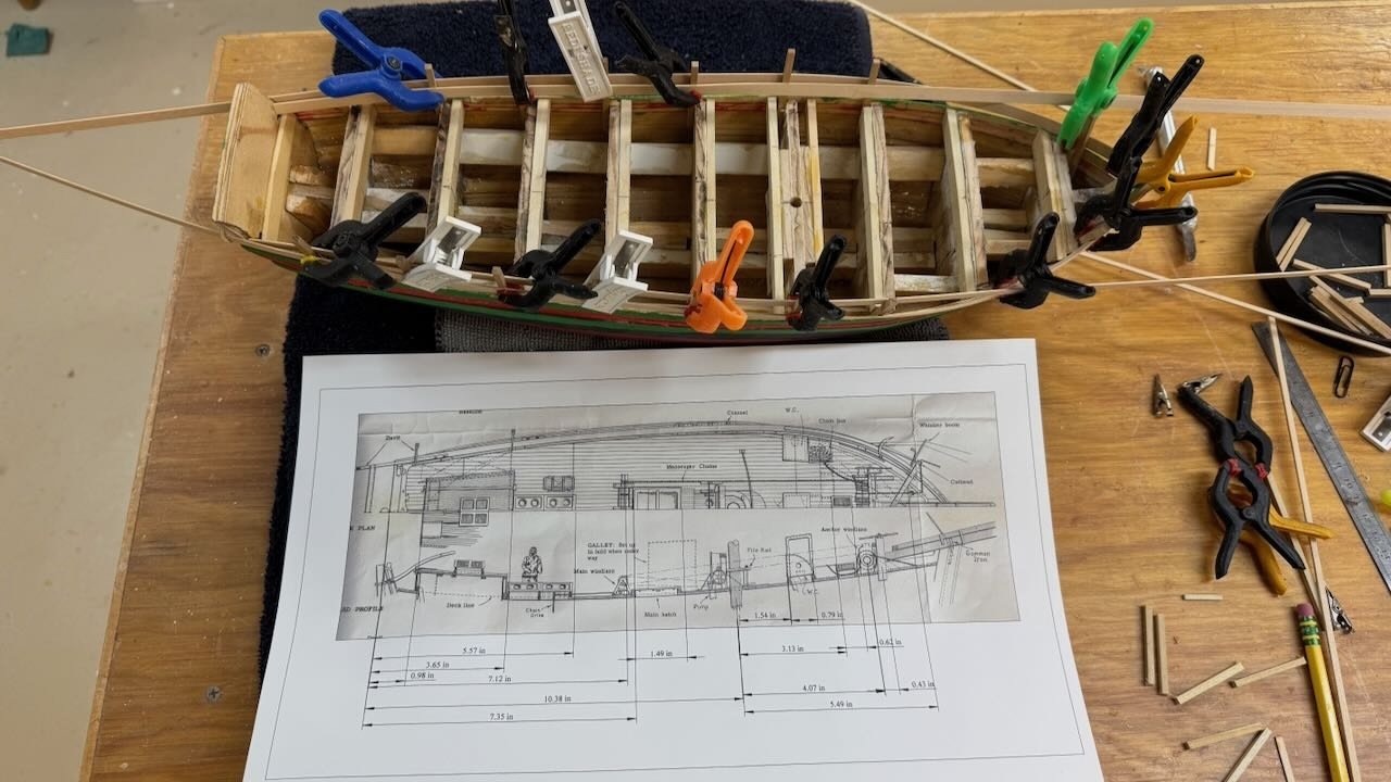
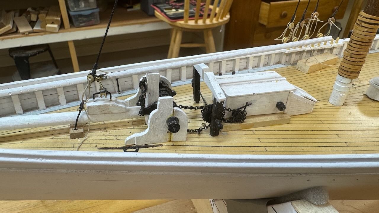
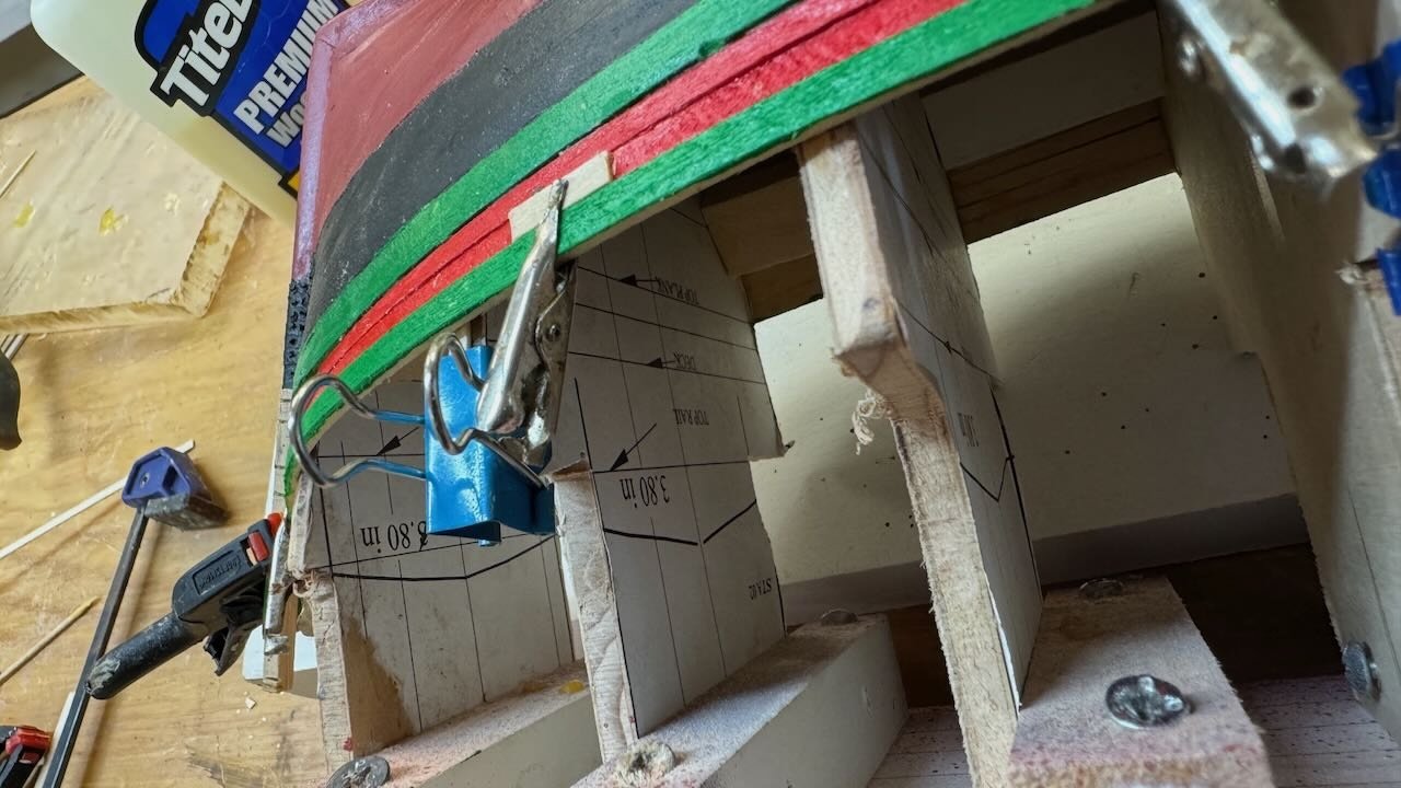
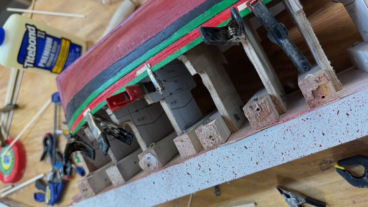
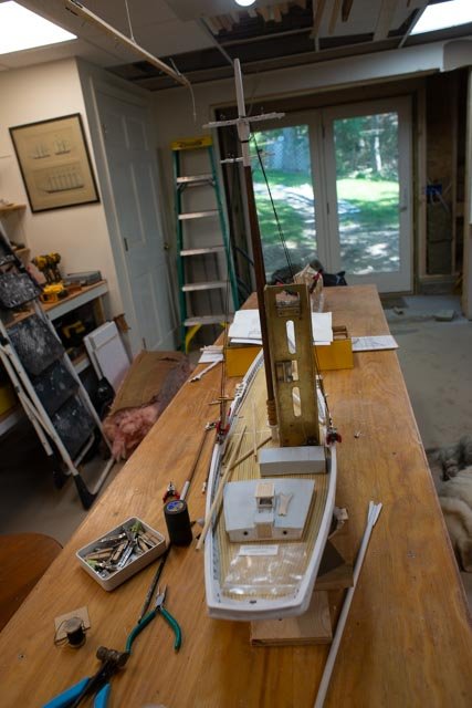
12. we are back to work This update is to celebrate the resumption of my build of this fun schooner. During the past year I diverted into the arctic where half of my current and near future builds are planned. I hope to continue in parallel with arctic stories and vessels and the Boothbay region shipyards, stories and vessels. The real live full-size work in our town this year is the rebuild of the vessel Niagara from Erie Pennsylvania. I have been down several rabbit holes over the years following the Ernestina Morrissey and Bowdoin rebuilds but have chosen not to focus on this area. I will visit a few times and what I learn I will share on whomever has an open log. She is quite the popular vessel, so I am sure I will find one. The first event that got Elizabeth Howard off the shelf was our annual model show in Bath, Maine. This year we moved to the shed that houses Maine First ship, the 1607 Pinnace Virginia. I stood up the masts and added a few shrouds just to have some visible change. The intent is to include models that are being built as a part of the show. In the view below she is among several other builds and anxious to return to the shop and not to the shelf. 1 here she is at the show in Bath me. In my posting of last year, I showed the photos that I am using to figure out how best to show the deck. My current activities include adjusting things to better fit the dimensions that I have extracted from the photos. 2 here is image showing a printout of the fore deck photo with hand measurements. It’s very low tech as the view shows the dimensions on the photo compared to the 11 inches bow to foremast. I also realized that the foremast head stay is not going to the samson post, so I needed to move that aft and then, like on other schooners, rig an iron loop from deck structure around the bowsprit to take the load of the lower foremast stay. I also have rebuilt the bowsprit so it can now come aft to the samson post near the windless. Next up is the windless and its machinery. Probably 10 years ago I bought a “fisherman windless kit “ . It has been sitting in a box all these years so now is the time to use it. 3-5 here we see first setting the main mast and rigging the shrouds. One can also note my arctic build Gjoa is at the far end of the worktable, so I can divide my time. The other two deck overviews show where we are starting, with the kit windless in place……. something is just not right I find it is missing a key ingredient, a direct drive wheel to connect to the donkey engine that surely would have been there. Looking even more closely to the photo above I see what I wanted to see; a second set of bitts just forward of the engine box, very fuzzy but clearly with a flywheel. So, borrowing experience from my schooner Bluenose build, I went ahead and had some fun. Here is my low-tech approach to adding a drive gear to the barrel. These 4 images show: First attempt to simply cut the “barrel and drill a hole to receive an extended shaft to hold the gear. This was an oops Second attempt when I realized I needed to shrink down the spool to make room for the gear drive. Drilling the winch to receive the other end of the shaft Using the drill press to carve two new winches And here is the partial reassembly. I will need to add some chain and the breaks for the anchor windless. One of the details I like in this option is the second windless is obviously a higher speed than the big windless barrel and more reasonable for raising sails. All for now I am just happy to have at least started again.


-
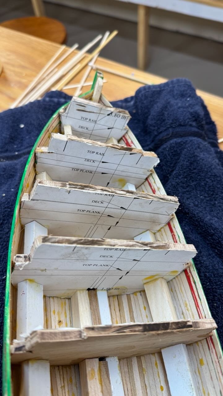
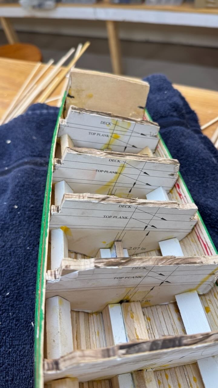
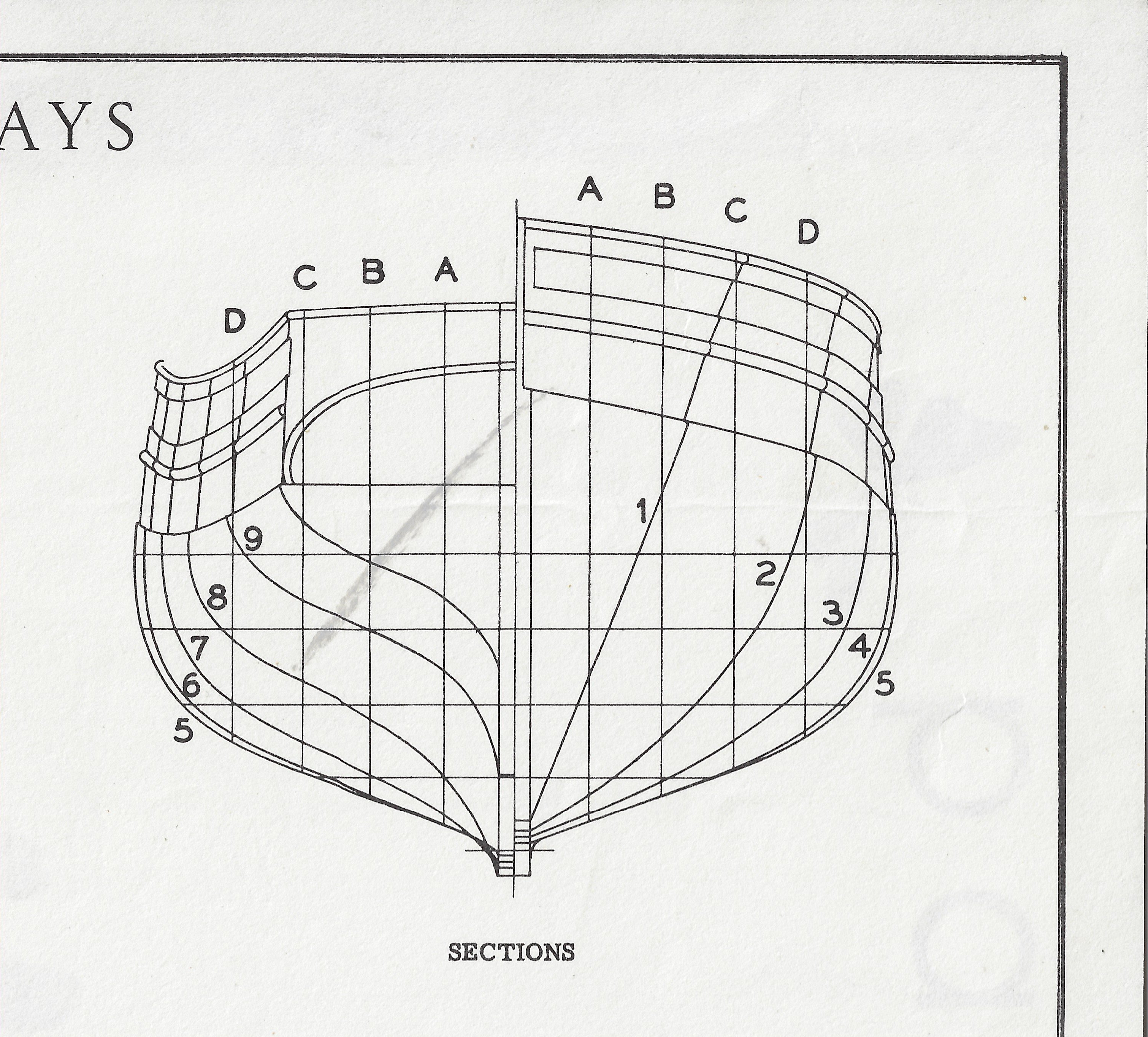
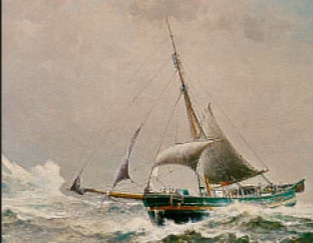
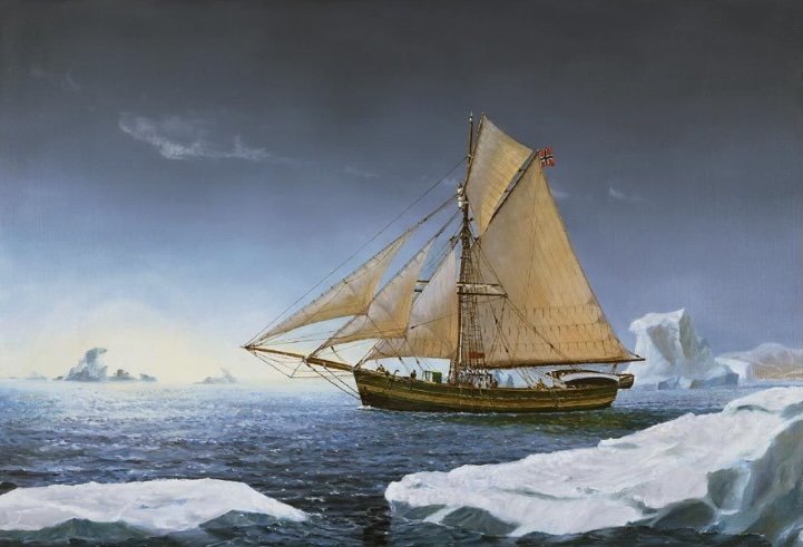
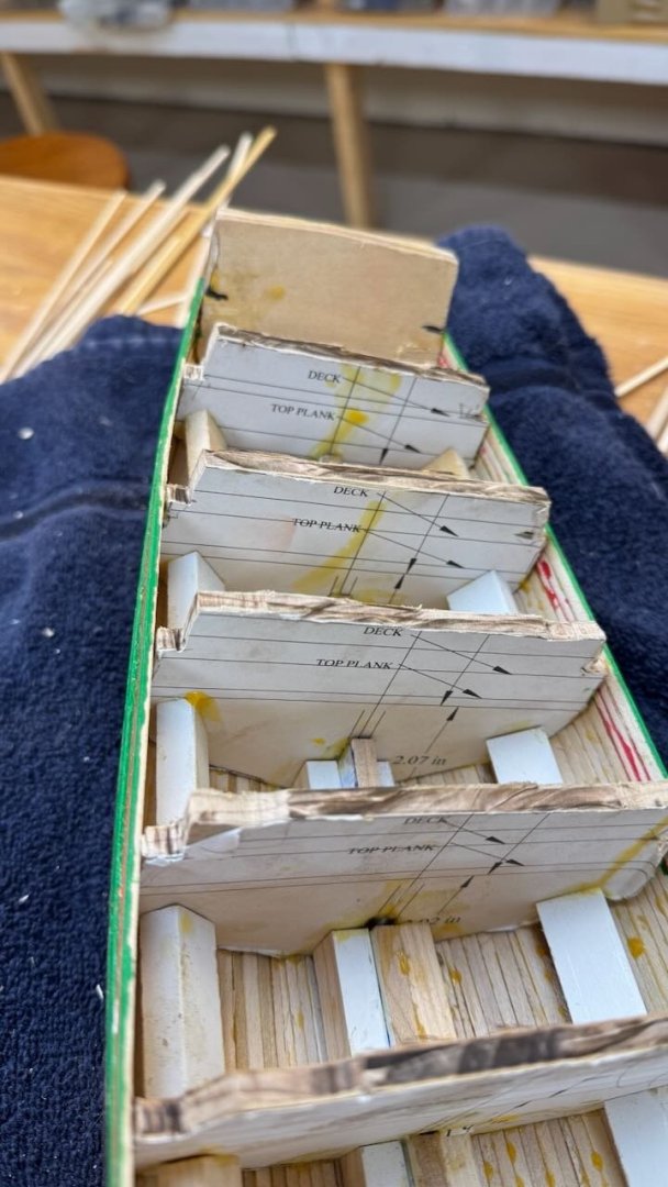
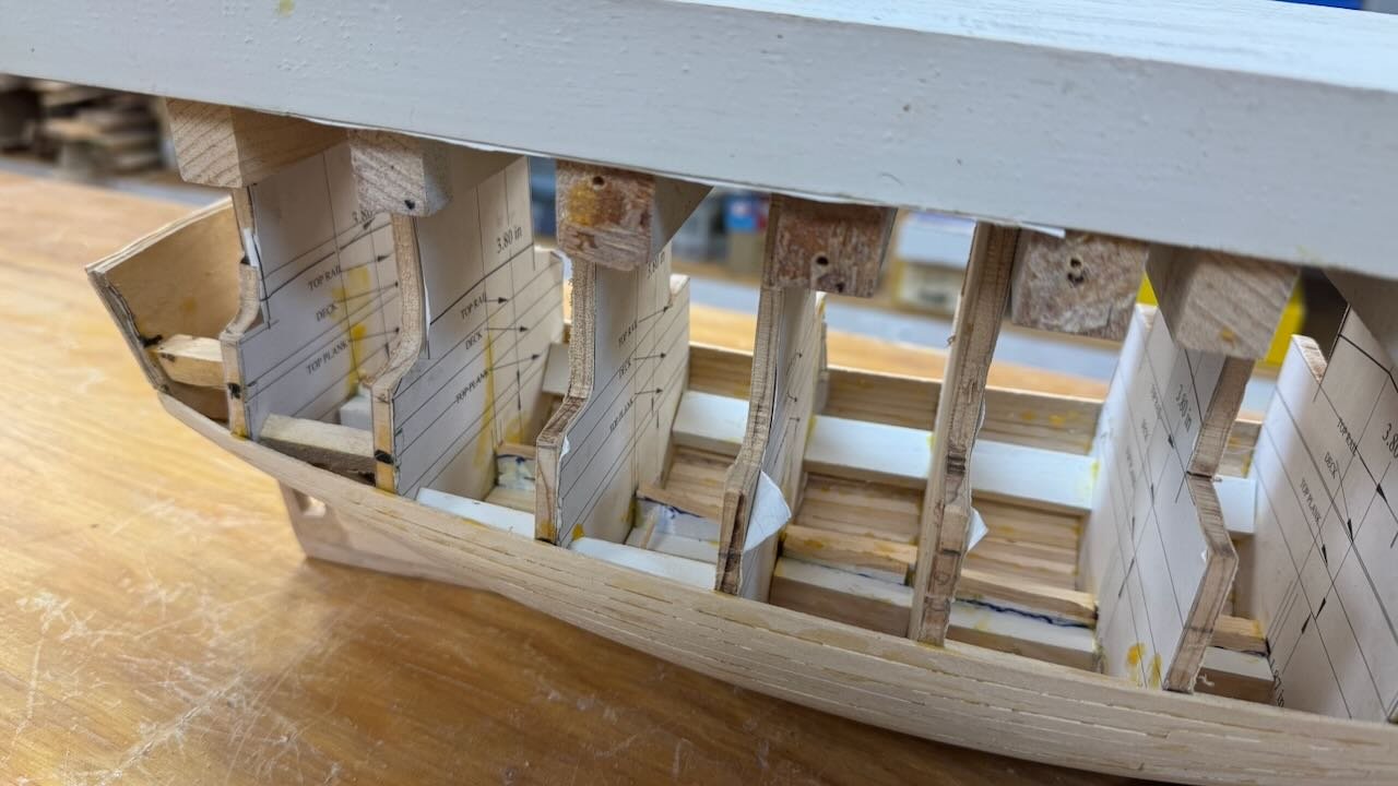
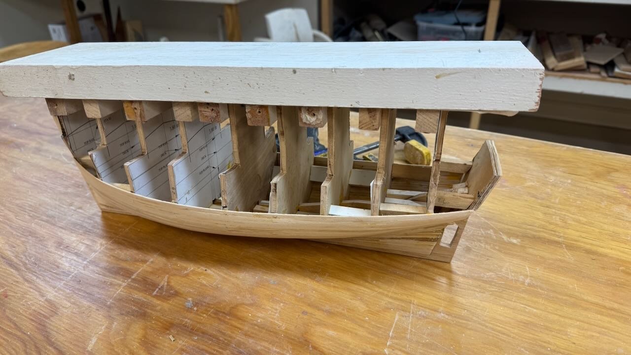
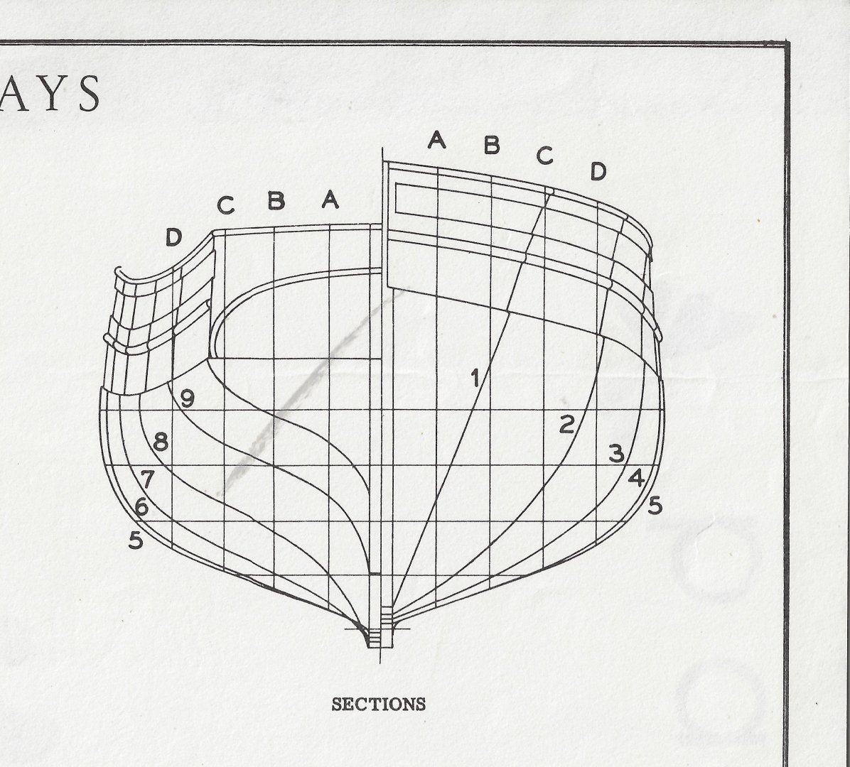
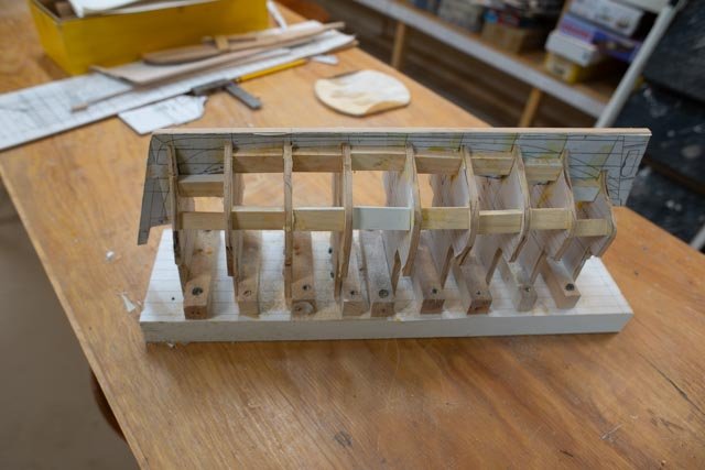
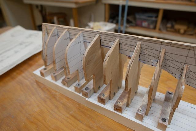
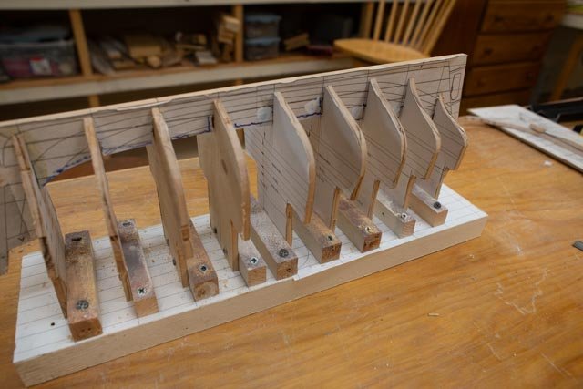
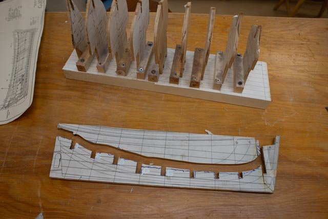
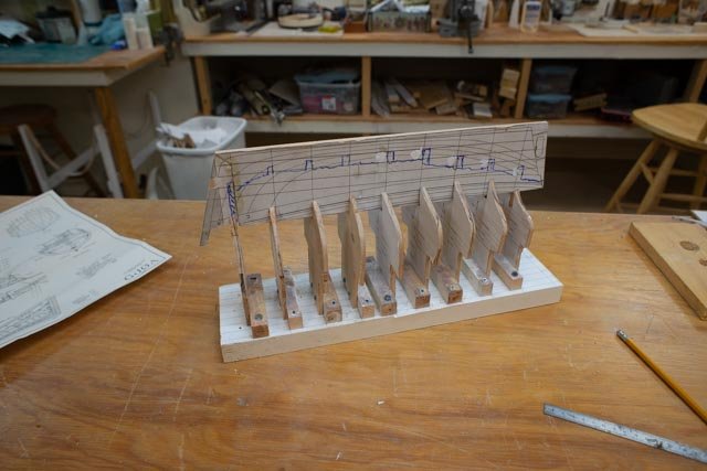
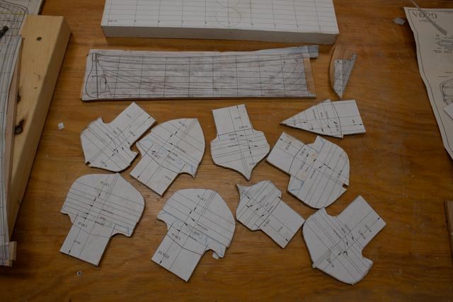
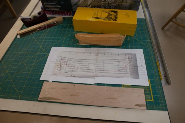
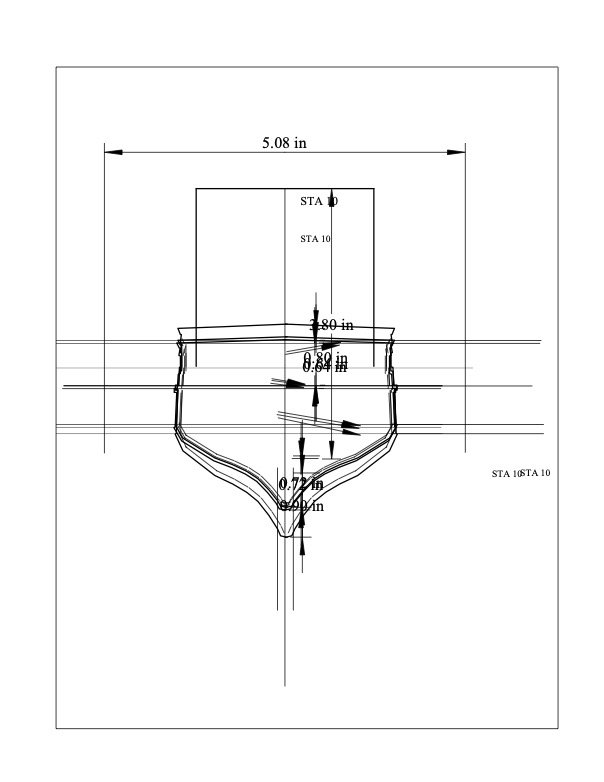
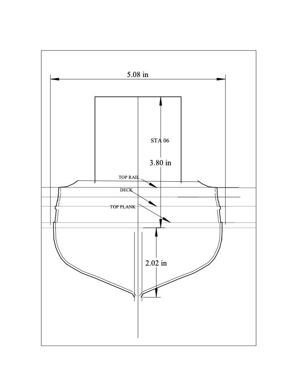
02 Starting the reading and preparing Drawings In preparing for my builds there is always a lot of fun reading. I just added about 8 books to my library, [ it's like stacking fireplace wood before winter] and I am sure more are in the wings. I got the Fram Museum illustrated diary of Amundsen’s voyage through the passage, a joy. I also bought the two-volume reprinted [ English] diary that Roald wrote. The publisher printed it in the faint broken font of a 1910 typewriter. What fun This build is but a chapter in the tale of the Scandinavians. I believe my tale will include: • Nordenskiold on the Vega making the Northeast passage 1878 to 1880 • Nansen- Sverdrup [FRAM to be another build but same story} 1893-1896 • Sverdrup FRAM. Canadian Arctic 1898 – 1902 • Amundsen Gjoa Northwest passage 1902-1906 • Amundsen FRAM Antarctica 1910 -1912 • Sverdrup/Amundsen Maud 1917-1926 Before deeper study these are my understood points of reference. Mostly from other reading or recent internet sources. I hope to expand my understanding though this winter as I build the two models. Nordenskiold is our starting point. There is some cross reference as Sweden and Norway were not separated until 1905. My reason to pull this story in is the geographical relevance, but more to our mission, a study in the evolution of active exploration vessels. The Vega was a steam powered bark, a Sealer. She was launched in 1872. Many of the vessels used by explorers up through 1913 included a wide selection of similar whaling/ sealing steam powered barks. Robert Peary used them, including the Winward which the year before had recused Nansen from Franz Josef land. Greely and Hall used them 1860’s to 1880's, and MacMillan used them from USA up through 1913 and found much difficulty. He was finally rescued by Robert Bartlett in 1913 after being in Etah, Greenland for 4 years. Nansen understood the effects of ice on the hulls though over wintering, and FRAM was all about the shape. She was quite successful. The fact that Amundsen not only took her to the Antarctic but used her design for the third vessel Maud speaks to the correctness of “fit for purpose”. Gjoa was a 1872 Norwegian fishing sloop [ cutter rig ]. Amundsen understood the need for less than 10 feet of draft, and a small profile to be able to maneuver through the narrow and shallow inshore passages which he both expected and indeed did find. He had a new type 13 horsepower engine that could burn many things. I hope to learn more about it. I look forward to the details by reading his diary. Off to the drawings. There are several exchanges in the MSW logs about drawings for these vessels. The models of Gjoa are apparently not currently available as kits. Dialogues suggested that the Model Shipways 1950 vintage drawings for their solid hull kit were even better than the expensive ones from the Oslo museum. I found an old Model shipway kit on eBay and thus I have a set of prints. Scale….I plan to build this vessel at 1:48 as that is the same scale as my Schooner Bowdoin. I will show these vessels side by side as an extended chapter. It will discuss the influence of this little gem of a vessel and its impact on MacMillan programing his schooner in 1920. The scene….it is too early now but starting out I think it be good to show her moored in ice /water as she spent over 14 months in what today is Gjoa Haven, Nunavut. Working To change the scale of the drawings I scanned the lines, added them to TurboCad…simple 2d cad… and traced out the stations and what I call the “keelson” assembly. The first 3 images show the Turbocad effort. First is the rescaled line drawing followed by a typical station layer. I added lines to mark the top plank [ planks are thicker below this line][ then the deck and the top rail. The 3rd image shows the transom that needed to be stretched to accommodate the angle of the transom from the vertical line. The next two images show the keelson drawing rescaled in front of the old kit box. Not sure what I will use the hull for and all the other stuff all went into general supplies. The stations are all printed out and glued to 4mm plywood. The next two images show the marking and cut out of the keelson assembly. I used a maple blank for this piece. The paper plan is glued with kids glue, so with a simple brush of water it will all come off. The final three images show front or back views of the glued stations and then the overall with the outer blocking supports. Next up is a slower process...it is all the prep needed before planking
- 55 replies
-
- 5
-
-
- Northwest passage
- Norway.
- (and 2 more)
-
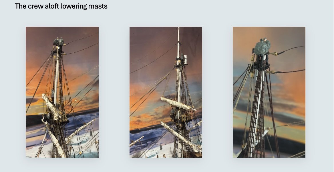
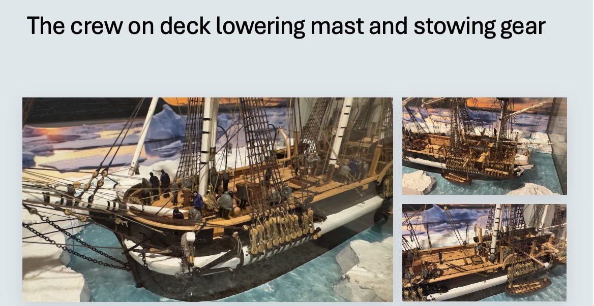
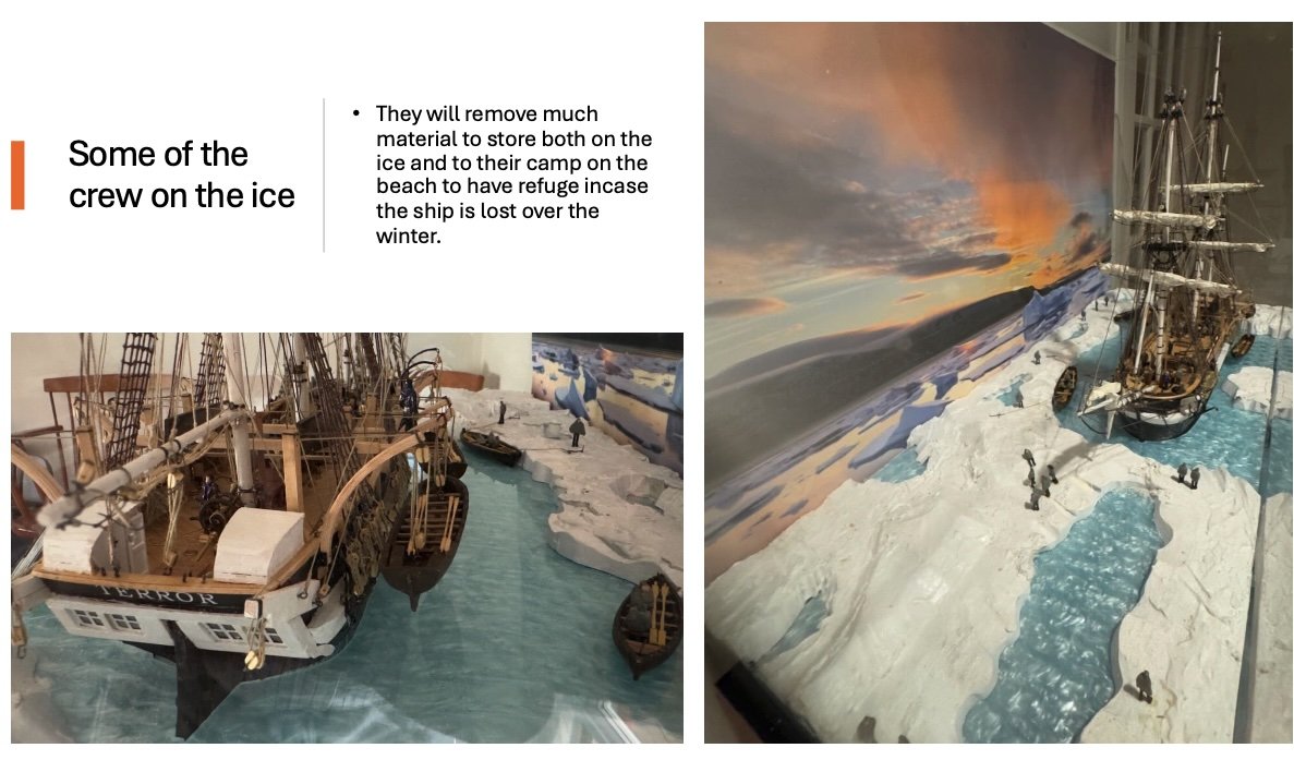
Just a postscript. First…Where does one keep a diorama of this size? Here we are in the study. Perhaps it is now the arctic room. Not sure if this is sustainable but it's good enough for now. Second… I was asked to give my talk a second time and wanted to avoid carting the big diorama around. I made up a few slides to focus on the story. I just wanted to save them into the log. Thanks all ... this has been a journey Jon

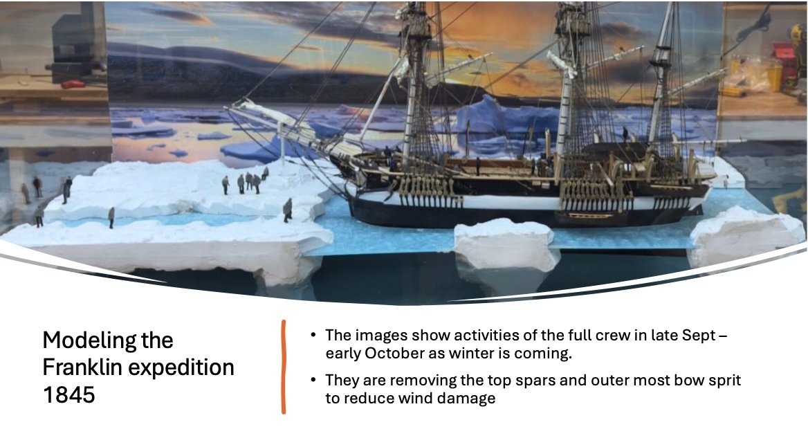
- 62 replies
-
- 6
-
-
-
- Arctic Exploration
- OcCre
- (and 2 more)


.jpeg.bd9084bd9ae0b03b794b4cb5bc49009d.jpeg)
.jpeg.b2d5ffd119700daf41731331aa56e4d0.jpeg)
.jpeg.2d4259d7b7e35b5caf93250e186786b0.jpeg)