


Jond
-
Posts
874 -
Joined
-
Last visited
Content Type
Profiles
Forums
Gallery
Events
Everything posted by Jond
-
 01 The Beginning. This build is the first of three I plan for the next series of stories. Over the next year, I plan to return to Greenland via Iceland following the Viking trail. That is to the best of my knowledge the beginning of the story of European explorers. To Complete the story of the Northwest Passage, begun with my recent build HMS Terror, I will have two Norwegian builds, Gjoa and Fram. Finally, my last of three builds will be to go along with my planned trip to the Greenland settlements. I will build a Viking vessel. First up will be the two Norwegian vessels. Fram will be a kit build and follow this scratch build of Gjoa. So let’s get to it! The cutter Gjoa was the ultimate winner in the search for a sailing route through the Northwest passage. I first learned of this vessel several years ago while studying the life and times of Donald MacMillan and the schooner Bowdoin. The Schooner Bowdoin was built in our town here on the Maine coast in 1921. That story is with my build of Bowdoin that I display as a diorama showing her second overwinter experience in the summer of 1924. In the story of MacMillan’s early life, and the issues that led to his having the Schooner built to his specification, was his research into other experiences. He was fascinated with the Fram story of a round bottomed vessel designed to survive mid arctic ocean ice. He also realized after all of his personal experience, that Amundson got it right when he chose the small sailing vessel with its auxiliary engine to find his way through. The relationship of Macmillan study of these two vessels demonstrates the value of their design. By example, Admiral Peary had MacMillan with him on his last venture to try to get to the pole. Their vessel the Roosevelt, built in 1905 at Bucksport, Maine, was quite different. It was quite big and powered by a 1600 horsepower engine. It had in Bob Bartlett a great captain to smash their way up through the Kennedy and Robeson channels to the shore of the Lincoln Sea on the North coast of Ellesmere Island. They got there yes, but when they returned to New York the following year, the vessel was in sad shape. Gjoa did not smash its way anywhere. She was the right size to squeeze through the shallow inshore waterways south of King Williams Island. After staying in Gjoa Haven for two winters and spending one more winter further west, she sailed into San Francisco harbor as a hero. There are other builds of the vessel and a current one that is a must read for both research and beautiful craftmanship of this vessel. My build is once again to build a prop for telling a tale. I am scratch building it in the same scale as the Schooner Bowdoin, so they can sit side by side and one can appreciate the comparison. One tale will be about Gjoa and Fram and their influence on Macmillan and the other is of the great man Amundson at both ends of the globe. As I understand it, he took Fram South in his race against Scott to get to the South Pole. Time to chase up some drawings.
- 55 replies
-
- 6
-

-
- Northwest passage
- Norway.
- (and 2 more)
-
Chris, Keith, Greg Thank you for your kind comments. Greg the lathe came from my past brother’s shop many years ago. He had bought it as a combo that sherline offered. One removes the lathe motor assembly and connects the mill “stock” assembly including its motor. I am able to switch back and forth. I also have a normal midi lathe and except for tiny things too small for the midi, I mostly use the sherline as a mill. My brother scratch built some 25+ steam engines. I on the other hand have yet to machine any metal parts. I really valuable it most when drilling tiny holes and am concerned about where they end up. 🤓A small drill press is great, but i find it harder to drill fife rails and the like. Small holes through spars are easier too. i have a friend who is an excellent machinist, and he has been working on me to shape some brass fittings. My next scatch build is Gjoa and maybe it’s time for me to try.
- 62 replies
-
- 2
-
-
- Arctic Exploration
- OcCre
- (and 2 more)
-
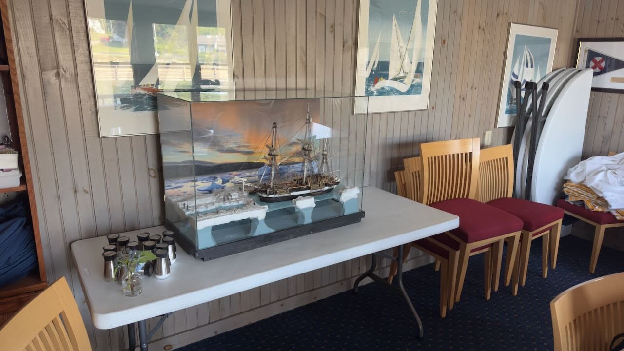
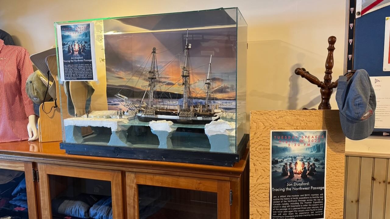
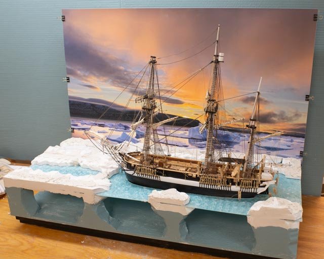
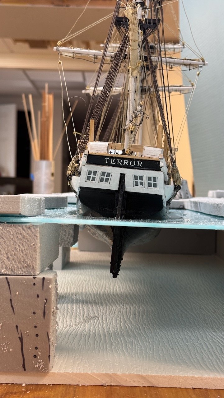
19….the end After a few months of resting on the bench and summer activities taking over my time, the punch list didn’t really get done. I also did not find the right adhesive to attach the black corners to the case. I picked her up and took her to the Yacht club for the summer art show, and then a few nights ago, I gave my talk on the general history of the Northwest Passage explorers and the vessels. The model showing HMS Terror laying at Beechey Island getting ready for winter was featured. My talk also covered highlights of how today one follows the path of the Franklin expedition. The images show her resting at the Yacht club after the art show, I was traveling in New Brunswick and missed it. Then she was in the lobby advertising the talk....Tracing the Northwest Passage. So, to the future. I will be next focusing on the two Norwegian vessels Gjoa and Fram for new builds, the first to be scratch and the second a kit. I also need to return and plug away at the Schooner Elizabeth Howard. And truthfully, I need to find a place for this huge box of a diorama. That is currently a mystery. I still have the alumnum strips and some day I will attach them. I also have the remaining soars and things to place on the deck. Our Guild has a show at the end of September in Bath Maine, and that will be fun too. So, Terror may rest , but no rest for me I guess. cheers jon
- 62 replies
-
- 6
-
-
- Arctic Exploration
- OcCre
- (and 2 more)
-
Keith one thing that should be said move often is that your sense of photography makes reading your updates extra valuable. I really look forward to seeing your work as time goes by. I have learned a lot from it. Another of your fine lessons is the sense of sequence. Getting all of ths tie off points in place early makes so much sense. thank you for sharing so well! Jon
-
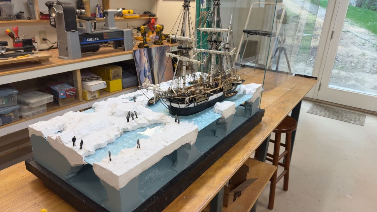
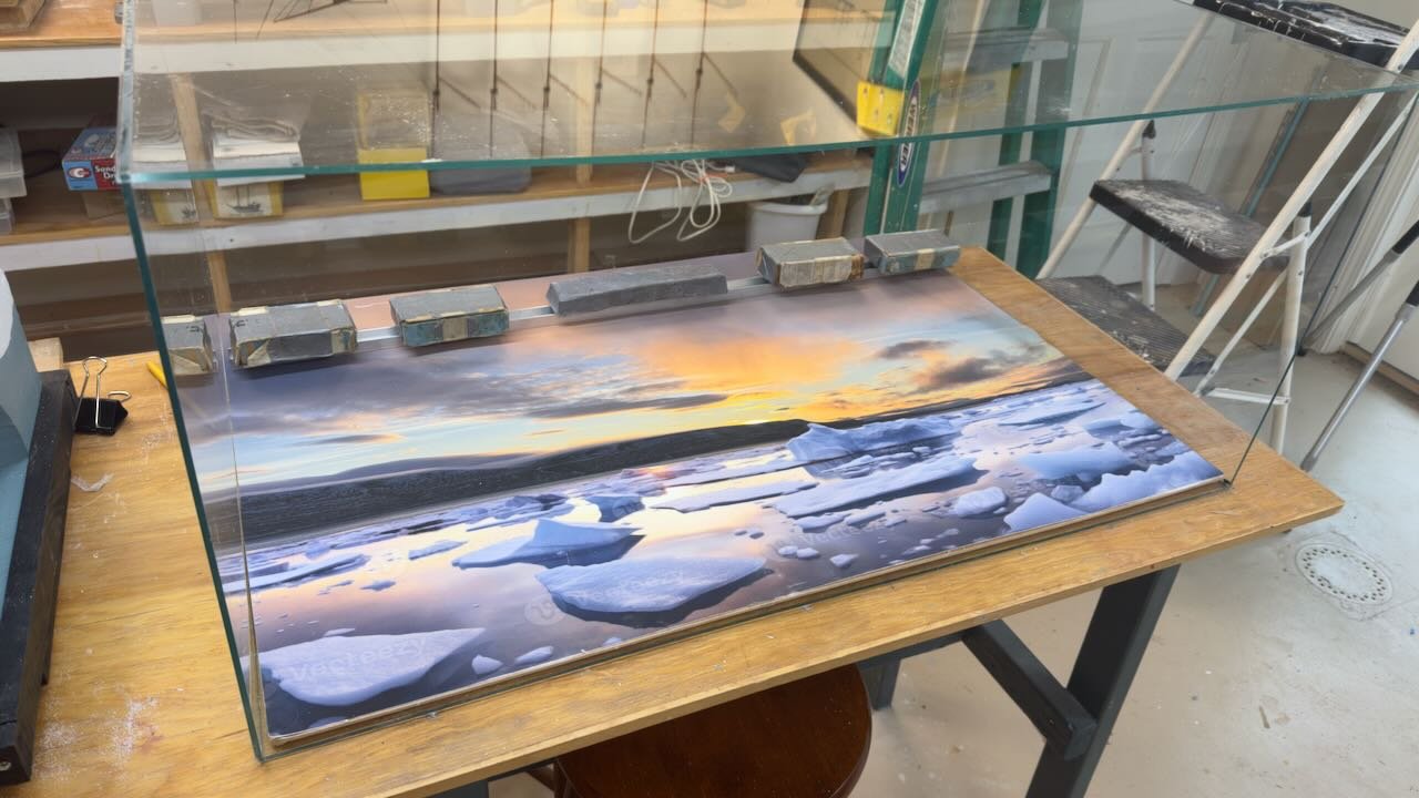
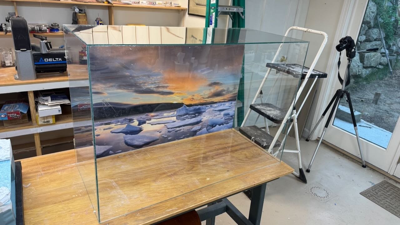
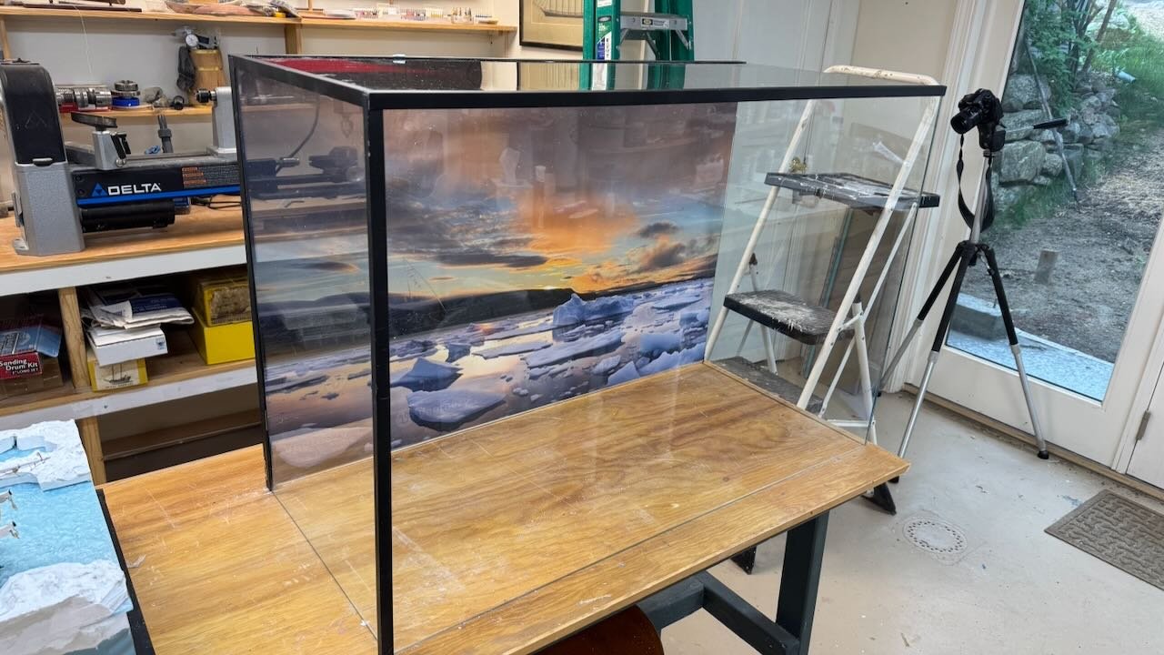
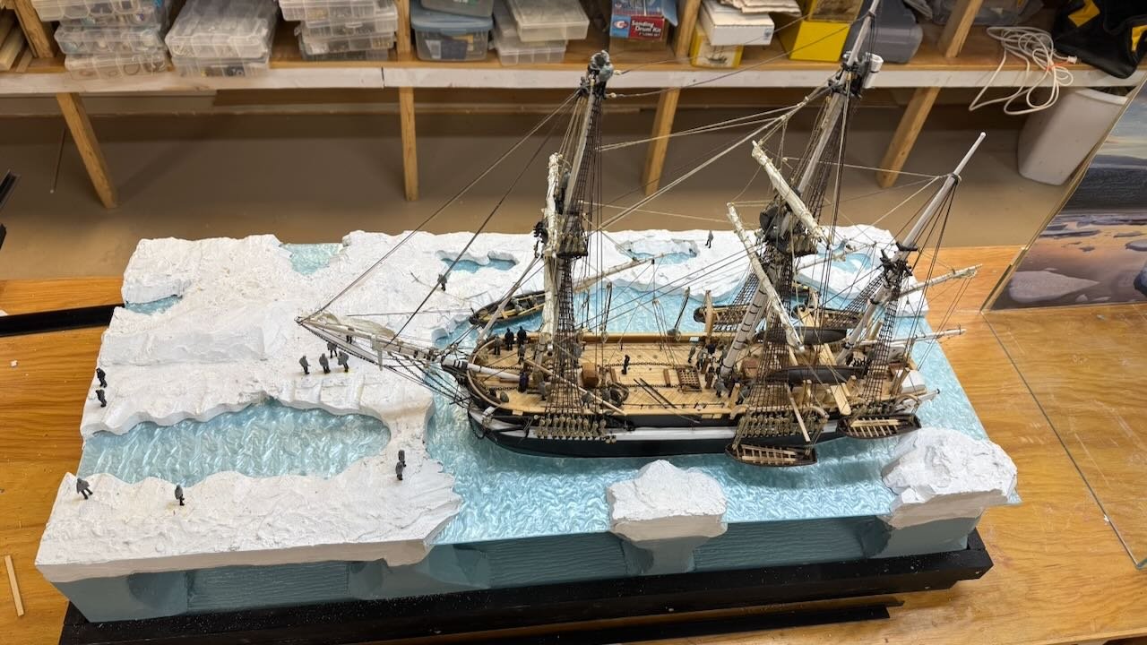
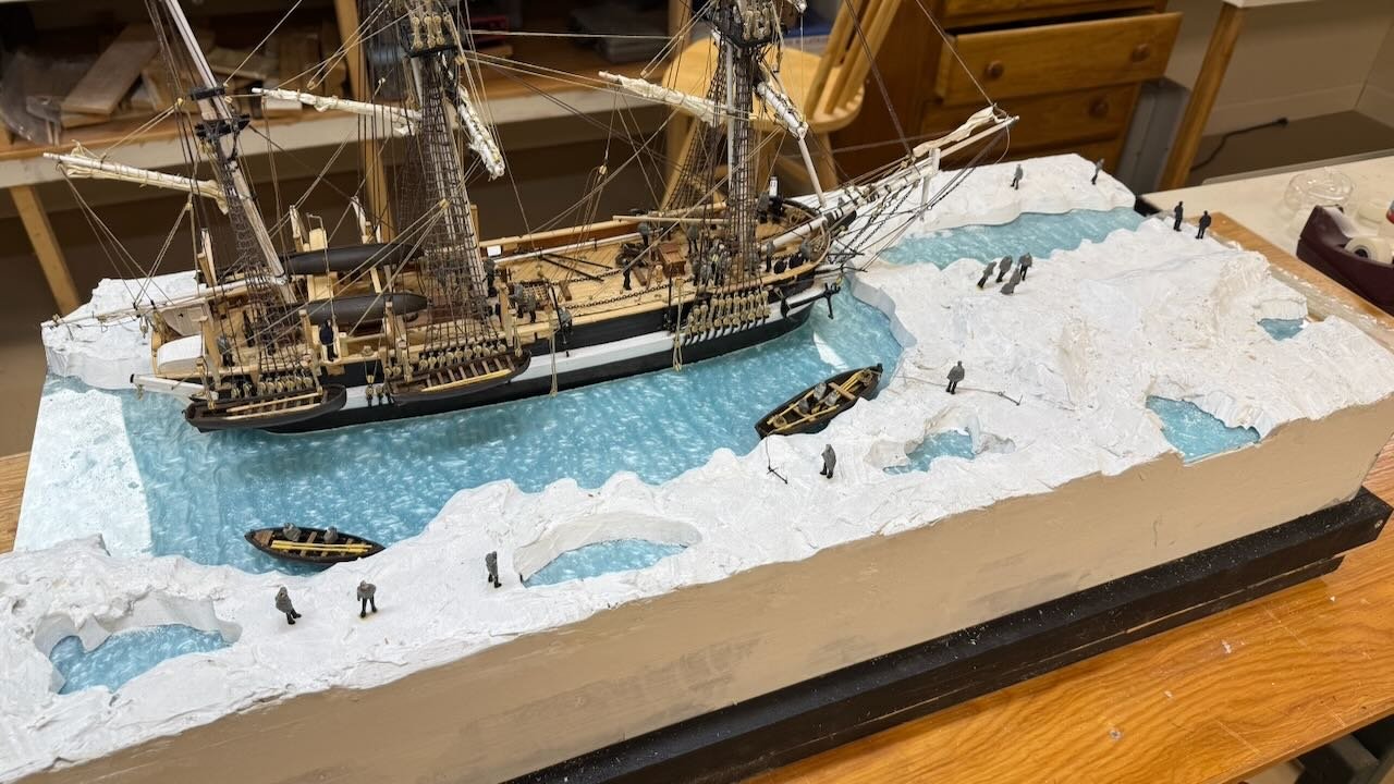
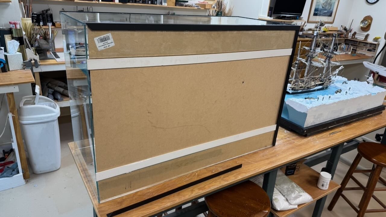
18. almost done; Setting crew, building a case and working off the punch list It has been a while since any real progress was made as spring finally came and outside work took over. I need to get the diorama ready to go for show and tell in July, so I’m back to work. 1 I took her to the local Guild meeting in May and posed a few questions. Happily, I receive some good answers: • the footropes on the yard arms would have been lines and removed, or as lines been inconsequential as to being stored in the racks on deck. I should remove them all and then store the two top gallant yards, along with some spare blanks. • How to build a case. Buy green Optix at Home Depot or Lowes. The Optix green means the edges are green and it looks like glass. The cost is about $50 for each 24”x36” piece. Then follow U-tube to see how to weld them into a box. • Support for my opting out to attempt to paint of wash or fool around with coloring within the ice, since the back lighting is early morning. I am no artist and the white with more added snow will be just fine…..I hope . I can always change my mind. • I had about 10 crew on board, and the group all agreed that more crew would add to the story. So after much yard work, and a detour to cut down two previous dioramas that are too big sit on shelves. we are back to work. 2-3. here a few days back I had many of the crew located. The full crew including officers and scientists etc. was 64. In these two images I have 50 placed. 4-5 here was an adventure. How to incorporate the poster into the case. A key issues is that glue between acrylic and other materials is just not recommended. My approach was after cutting the 16.5-inch top piece, I took the remainder from the 24” inch sheet and cut it in half. I then welded it to the top and bottom of the back. I then laid the poster on thin mdf on 3/16” strips of wood using normal wood glue. I used aluminum channel and weights to keep all as flat as I could. In the second photo of the completed back, one sees the two wood strips adjacent to the two back strips. They are extended past the sides to hold the poster in place. I hope it works… 6-7. here we see the welded up case…my first so there are a few oops…. In the first view we see the green edges. For simplistic affect I agree the green choice was a good one. However, every oops is there to see. In the second view I have taken aluminum strips and spray painted them flat black over auto primer. Before I proceed to add the aluminum, I need to learn how one glues painted aluminum to acrylic. I thought to try clear silicon sealer, but it failed. I guess I need to experiment. 8-9. after more thought, I decided to take the remaining figures and put them all out. There are 21 on the ice and 39 aboard. That is all but 4 of the crew who may well have been up and about on the early morning in the later fall of 1845. My real reason was to show in the story how huge the crew of the adventure was. That huge size is one of the key reasons the attempt to traverse the passage became such a tragedy. These two views are both not what will be normal . the first is from the top and the second from behind. Next up is the punchlist and completion of the case. Then to move it, does it stay inside the case? I hope so and that is one reason I did not repeat my earlier uses of glass. It is just too heavy for moving. Happy summer
- 62 replies
-
- 9
-

-
-
- Arctic Exploration
- OcCre
- (and 2 more)
-
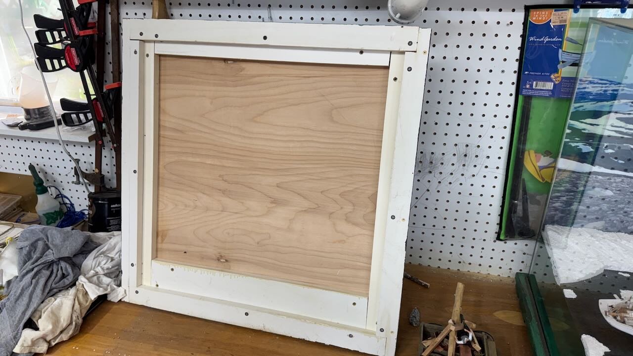
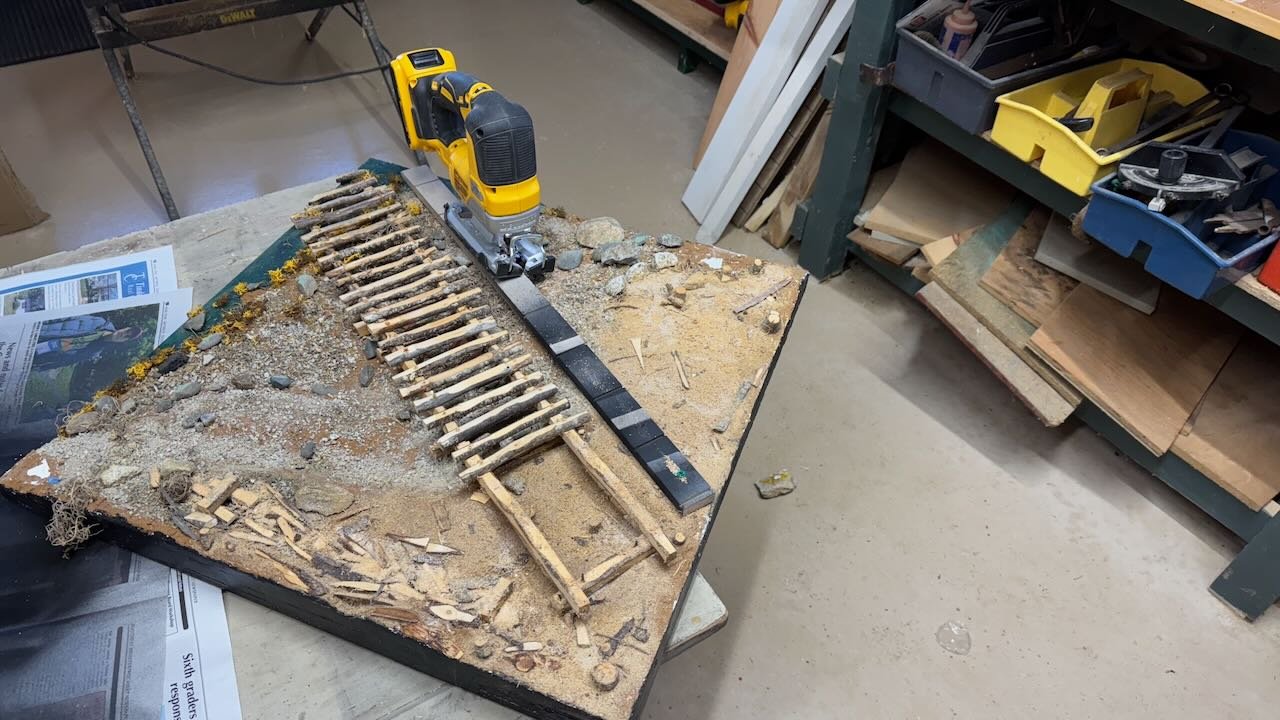
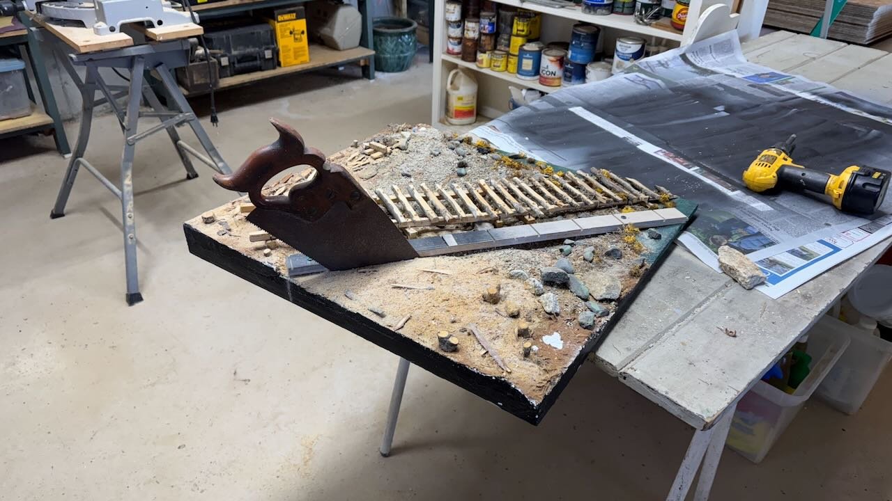
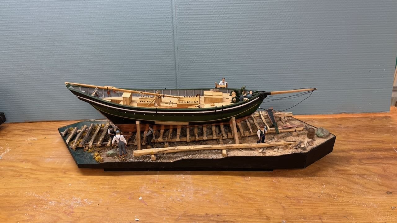
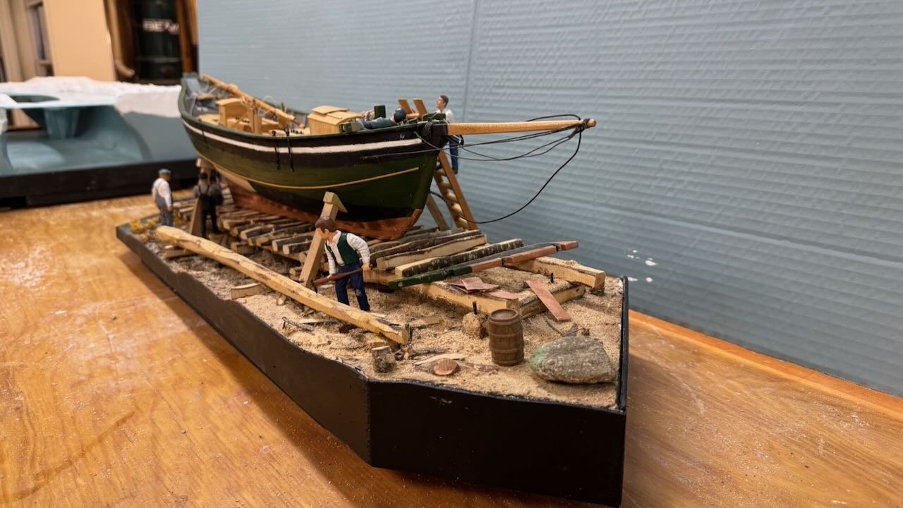
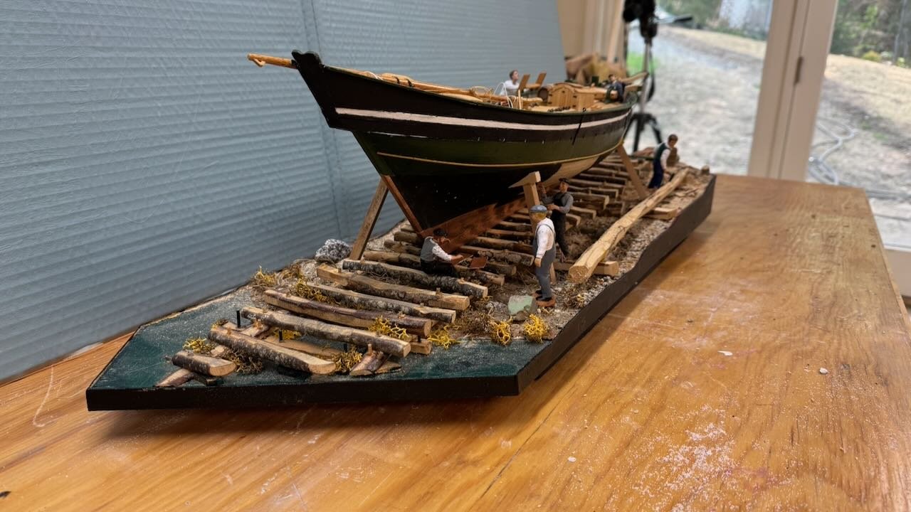
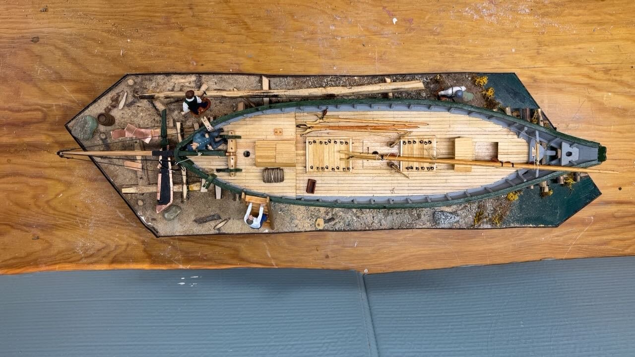
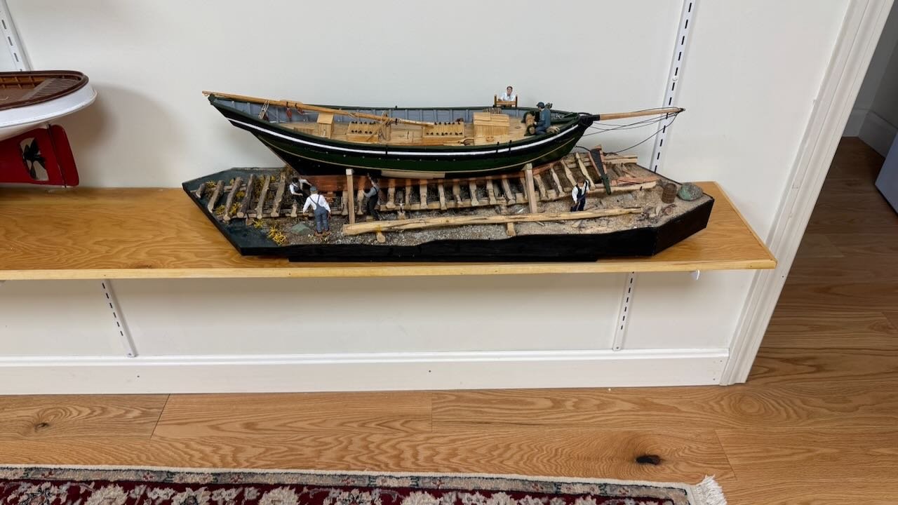
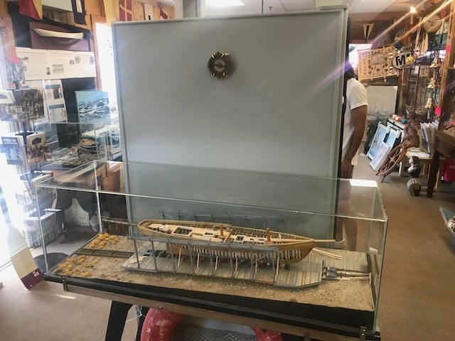
post 34 This one-time post is to update the life of the diorama of the pinky schooner Superb. As a reminder, since this is 5-year-old build, this pinky schooner Superb was the first built by the Hodgdon family of Boothbay in 1816. They are a still running active shipyard where the 6th generation is just taking on the leadership from Tim Hodgdon. I used the kit for Glad tidings as a material source and drawings from the Adams shipyard [ contemporary with and adjacent to the Hodgdon yard]. I have discussed in other logs that the museum Store in downtown Boothbay Harbor was closed after several fun years. It was a very unfortunate occurrence as today, some two years later, there still is nowhere sufficient to collect and share the 200 plus years of maritime history we have. Both dioramas of Superb and schooner Bowdoin had been relegated to my garage…..not nice. I have been concerned but as they had cases and it is heated, I felt they would be ok. In my recent build of the HMS Terror, I came to the time that one must considerer a home for the completed project. That is without building a new home. Before I get back to another build, I want to fix this problem. A two foot plus square platform is not practical for home display. The first option is to remove the vessel and put it on a traditional stand. That takes too much away from the story. After much consternation, a light bulb went off in my head……cut the diorama to a 10-inch depth and place it on a shelf. Then she can come to the model gallery and sit with the others. If we ever do get a museum type opportunity to tell the story, I could make a poster for a backdrop to regain the imapact of the larger format. So here is the renovation 01 -02. here the platform has been stripped of the vessel, work crew and loose parts. I then turned it up so I could remove the bottom frame that I will replace with a smaller one later. 03-04. here I am cutting. The power saw blade was too short to go through all so I needed the old fashion one to complete the two cuts. After rearranging the landscape, a little bit and focusing the work crew on the front side, I used some thin ply to band the cut edge and paint it out. I also added a small bottom frame to lift the platform off the shelf. 05-09. these shots show the completed rebuild on the work bench and ultimately in its new home shelf in the gallery. Not that many will get to see it, Superb is waiting for a chance to escape. Cheers
- 69 replies
-
- 7
-
-
-
- diorama
- Glad Tidings
- (and 2 more)
-
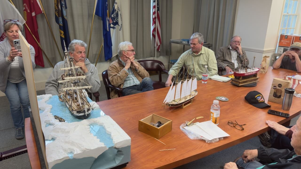
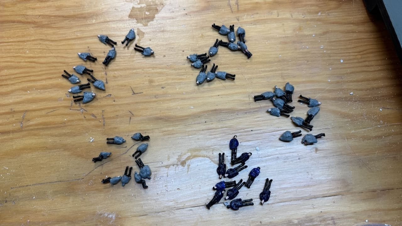
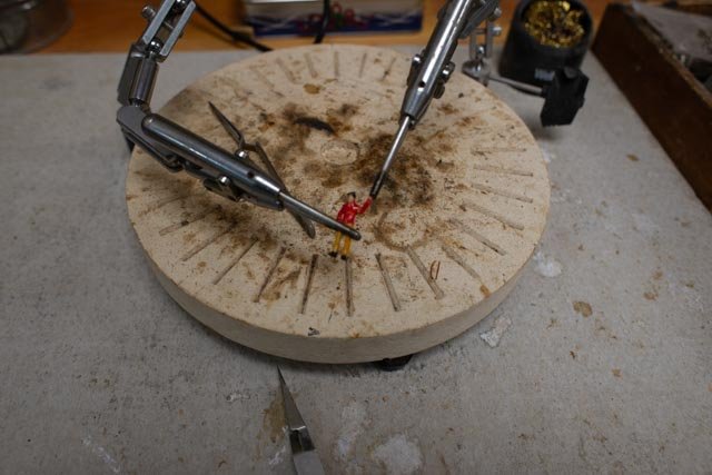
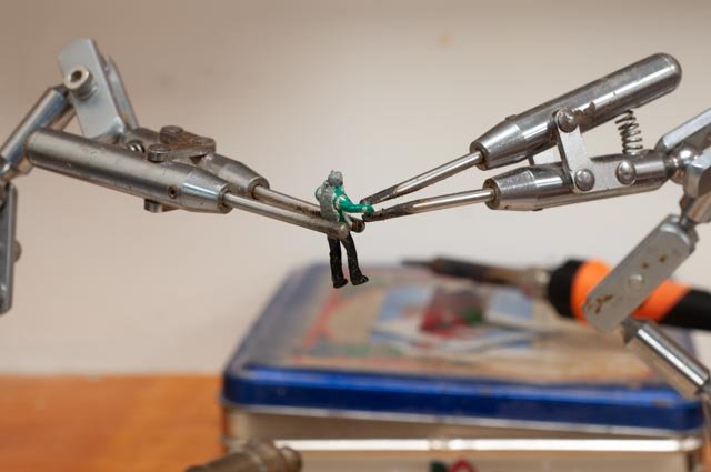
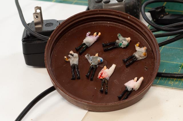
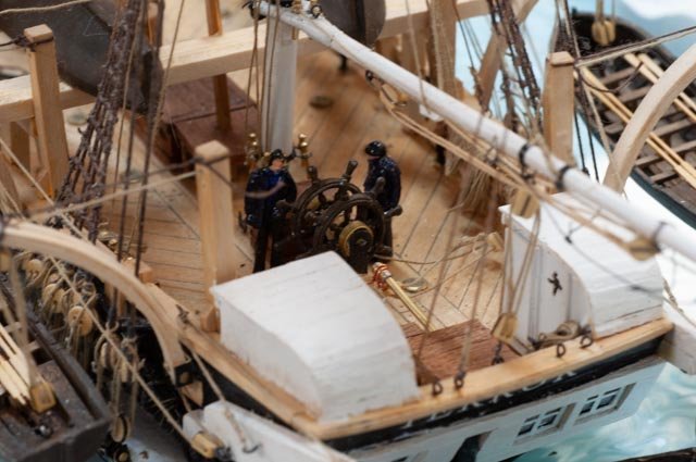
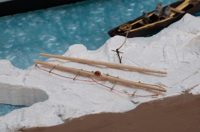
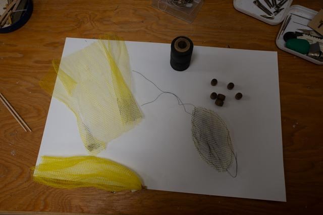
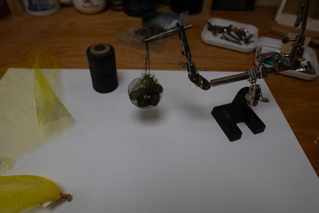
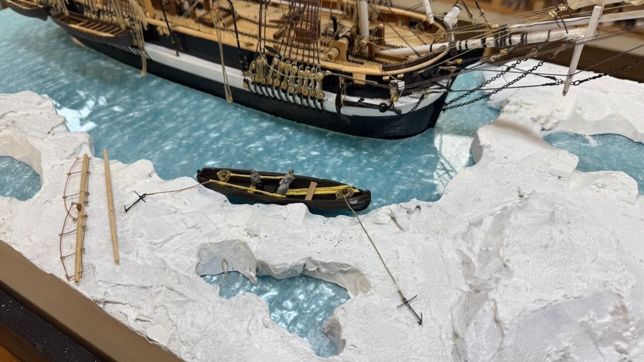
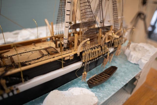
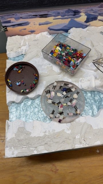
17. little people, little boats. Other little things It has been a month and slow. "little' progress gets made. Competition with spring outside requirements always interfere. I also I spent much time this month cleaning up and sorting the shop. This two-part update comes as I need to prepare and present the diorama to the local Shipmodelers guild. One is never totally ready for that…ha ha. First up is details and punch lists before the meeting and the second part will include the process to pick up and move the whole kit and bring it home again. The crew had arrived months ago and it is time to prep them and to start to put them to work. The 1:75 scale limits the choices. More importantly I am looking for a good sized crew. They sailed with some 64 people. It is possible that all were up and about at the same time, but I figure many were and 'many' is a loose number. Second what did they look like working in subfreezing weather. Here we go…. People……... I purchased a pack of 100 +/- figures, likely meant for a train station or the like. Taking the men, I wrapped them with some paper mache [ paper tower scraps and dilute white glue.] Then painted them light and after darker gray to simulate wool hats and sweater coats. The officers were selected as the 12 figures in coats, so I painted the coats dark blue and the hats black. The scientists perhaps were in civilian clothes, so I guess part of the officers in all black. About a dozen figures were sitting and that was fine. Everyone got black pants. I then coated the paper mache parts and officers with Mod Podge to improve the surface of the paper towel and hopefully add a little bulk to the jackets. 1-5 these views show first most of the crew in finishing steps of paint, trim, repaint, etc. Then I realized I need a few figures to be in action with arms reworked to hold lines or themselves to the rigging. I used the soldering station to maneuver them and went through 7 figures. the action figures have first application of paper mache. Finally to follow some protocol, I placed two officers near the helm to be first aboard. 6. here is a question of what to do. The two topgallant yards would have been lowered and stowed. I have gone ahead and started to add fittings to one of them. It would have been very awkward to handle and stow, but also a pain to disassemble. Perhaps I should remove the foot ropes. I am not sure and still thinking. Perhaps I think too much. 7-8. these views show an experiment. I bought some veggies in these neat little yellow net bags. I have always wanted to make a net carrying barrels on to or off of a model. Maybe this time is my chance. Using a little magic marker to blacken the martial and cutting it into a circle, I weaved tie lines and drew up the bag with 6 barrels inside. I think it is a nice idea but…. They would have done it after iced in to set up emergency supplies on the ice off the boat in case of crushing etc. The trysail gaffs just barely makes it over the side. Was there more rigging attached to the idle yard arm for this purpose? Finally, I note the trysail gaff is not long enough to reach the hatch. How would they have rigged for pulling barrels and other goods from the hold to the deck? Perhaps, like a whaler or other vessel managing such things at sea, there had to be more rigging spanning the two masts to get to the hatch and then the yard arms to get over the side. 9-10 the boats are now on board, and the main Pinnace is overboard. I made up anchors with brass wire, as any from fitting options that i saw seemed too big for a small boat. I still need more oars and coils. so off to the meeting this week. I capture what happens to transport this monster, as it most go two more times this summer. cheers
- 62 replies
-
- 5
-
-
- Arctic Exploration
- OcCre
- (and 2 more)
-
Thank you John and keith it is unfortunate the museum store in Boothbay had to close. I had three dioramas and a schooner there and enjoyed helping out with minor repairs to others from time to time. Now those models have all come home. The Pinky Superb built by Hodgdon in 1816, the Schooner Bowdoin built here 1921 and replanked in 2016 at Bristol Marine and Ernestina Morrissey Bob Bartlett's schooner completely rebuilt here in 2020 bracket 200 active years of Boothbay shipbuilding. the latter two also highlight my fascination with the arctic. Unfortunately continuing to tell the local story is a challenge. Your builds including your Red jacket are part of our Maine story too . Unfortunately both the pinky and Bowdoin are no relegated to my garage. cheers
- 62 replies
-
- 5
-
-
- Arctic Exploration
- OcCre
- (and 2 more)
-
Guy I am not an expert but I agree. I started to make them for Terror with a bend and thought to myself....this makes no sense. I then checked out the Mathew Betts drawings and went with straight. Yes they point in a little bit, but a smaller boat suspended worked out OK. Your doing a great job. I applaud you for persevering with the aluminum bow plates. I opted for the copper tape. cheers jon
-
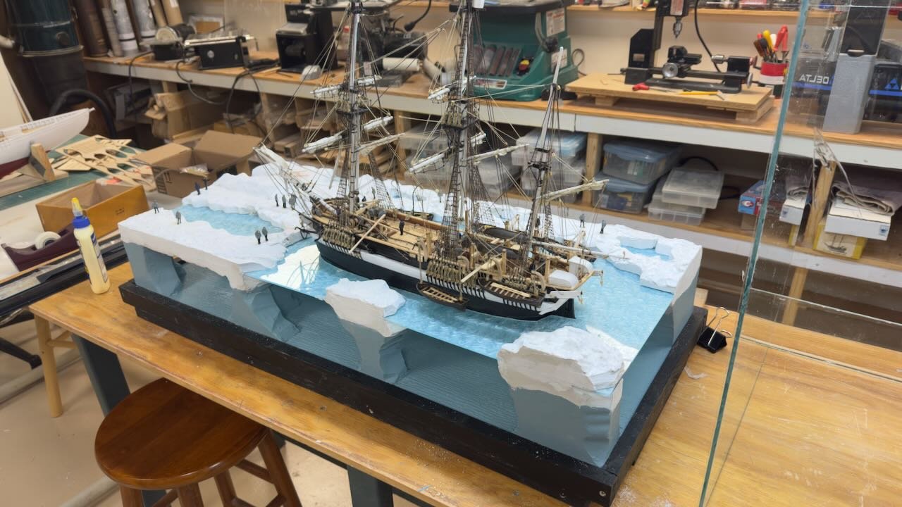
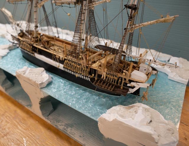
16. I wanted to record the process to build up the diorama, so it can be relocated for showing and it needs to hold the backdrop. As I have said before I am finding my way. 1-2 these images show the diorama upside down for fixing the base. I use scrap pine from storage…nothing is fancy here. The board on the back side is slotted to receive the 1/8 inch back drop poster. 3-4 with exposed surfaces all painted black we are turned right side up. 5-6. the poster is currently clipped to a thin MDF sheet. Once all is good, I will glue it down. 7-11 these shots show 5 views of Terror set at the time. Note the many lines and clips getting ready to add the small boats. Next up is to complete the boats and crew and figure out what they are doing. I have about half of the coils in place, so that continues as well. Finally, I need to enter a new world and decide….do I leave the ice as it is or do I try to paint it to fit in more closely with the backdrop. I will experiment first and then decide…. sometimes doing less is better than making a mess. all for now
- 62 replies
-
- 6
-
-
- Arctic Exploration
- OcCre
- (and 2 more)
-
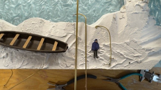
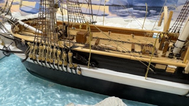
Keith "Jolly and Bob. thanks for the likes and encouragement Keith thanks for your consistent wise advice. I believe your solution is most accurate as well as your model is based on sailing when I would think these temporary davits would have been stored. For me however I believe no more than days before my diorama scene , these davits, on at least one side, would have been used to clear the deck.....so ...most images show a 26 foot +/_ 8 to [9 metre] Pinnace riding in the center. I plan to use the large kit small boat hull for this one. the question is....in my scene anyway.... how did they get that boat off the deck and launched. It is too heavy to heave. The trysail gaff probably was re-rigged with perhaps a 5 part line to allow men to raise one end and then swing it to the rail. then what? Perhaps at least for us amateurs, anything would be conjecture. My thought is they would transfer the first end, likely the stern, to the swingable davit. Thus the iron davit makes sense. Once they had it secure on the aft davit, the second end....likely the bow ...would be lifted using the trysail gaff, and the boat moved...., no easy task...to where the second end is over the rail in position for the forward davit lines to take the load. now. this vessel is bigger than the others that all have 5 part lines, yet manpower would have been he same. I suspect a triple block from the head of the davit would have been used. It would have made hoisting a bit more reasonable and the there is no way for a sheave in the metal pipe [ I believe]. There was nothing around except manpower to manage this heavy load. That being said, how big would the iron [ steel. } pipe need to be. I suggest to avoid bending easily at least 100 mm......moving to scale one divided by 75 to get say 1.3 ish mm. what I have was a 1mm from the kit supply...it just does not look strong enough. ter-15 -11. here is a photo showing....1mm as before that I feel is too small, 1.5 mm bent with copper wire soldered to make loop for block and a piece of 2.5 mm to compare. I set the kit boat and one scale figure to help visualize. the 2.5mm [ 3/32 tube for us]. would be just under 8 inches….I think too big. The center 1.5mm pipe would be just over 4 inches [100mm] and I think that makes sense. I will go with that one. I agree with you Keith about not being set while sailing and will only have them set on one side and maybe put a second set resting in the deck storage for the other side. now to decide which side..😄 cheers
- 62 replies
-
- 4
-
-
- Arctic Exploration
- OcCre
- (and 2 more)
-
15 continued rigging and work on diorama This is a brief update of combined effort on both the rigging and the diorama. 1 this view shows the final underwater ice being added. 2. shows me playing with how best to use the small boats. Should they be in the water, perhaps on the ice as they began to transfer supplies to the ice in case the ship sank. I also started rigging the davits. 3-4 shows they addition of spackle [ joint compound] to smooth the outside of the Styrofoam that will be repainted as water below and ice above. The top surface is very rough at this stage. 5 here we can see the ice barrel has been added, the platform for navigating or the “ice plank” and rack for aft boats. I will likely show the two kit whale boats resting on this rack. 6 shows the beginning of work on the crew. I am using white glue and paper towel scraps to build up outer coats. I need both sitting and standing figured as some in the boats would be sitting. There were over 60 crew members and most of them would have been active on this day of mast lowering and preparing for the winter camp. We’ll see where that leads. I clearly have enough to do the whole crew. I will not try to show those Navy hats for the officers that were shown in the recent TV series, I cannot believe they would have worn them when the temperature went down. Perhaps common sense and warm hats is an error common to us yanks. 7-9. these views show he anchors in place along with just about every line. The lower coarser sheets were tricky. The middle view shows my first attempt at the iron [ steel?] davits for the middle boats. I am a bit concerned as this location would have included the largest pinnace. I intend to have it off the vessel as the whole deck will be needed for the mast lowering exercise. However, what I have made does not look strong enough. I assume the trysail gaff would have taken half the load at a time to move the boat from center to over the side, transferring to the davits. More thought is needed here 10 shows the ice plank and celebrated that the davit blocks for all the boats are in place. I have yet to make them off as I need to decide how each will be displayed…. Up or down Next up is to complete the diorama and prepare it to receive the backdrop. The poster came the other day and is currently flattening before trying to install. Cheers
- 62 replies
-
- 4
-
-
- Arctic Exploration
- OcCre
- (and 2 more)
-
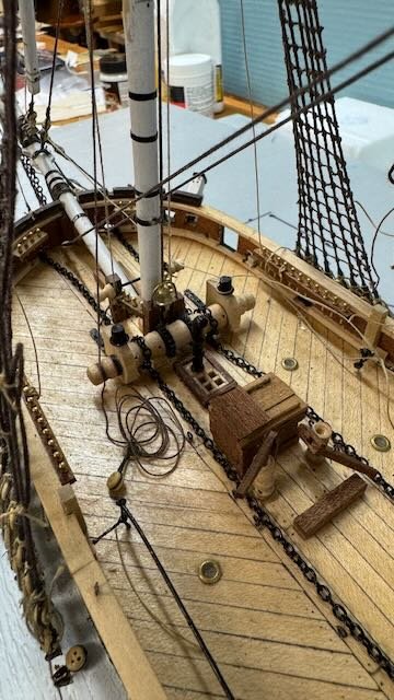
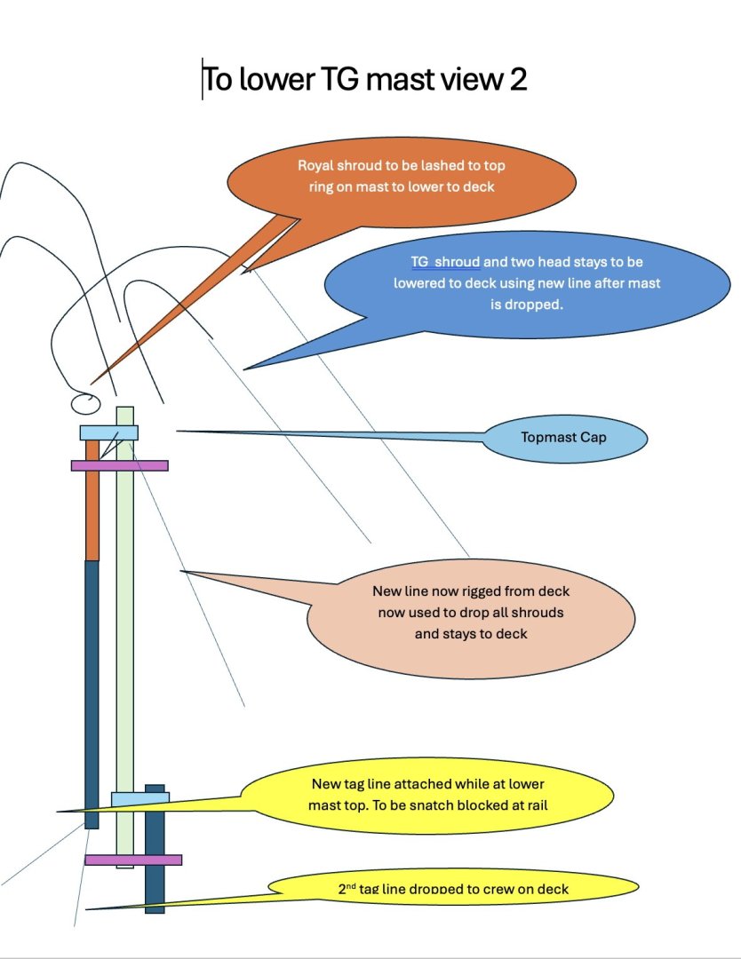
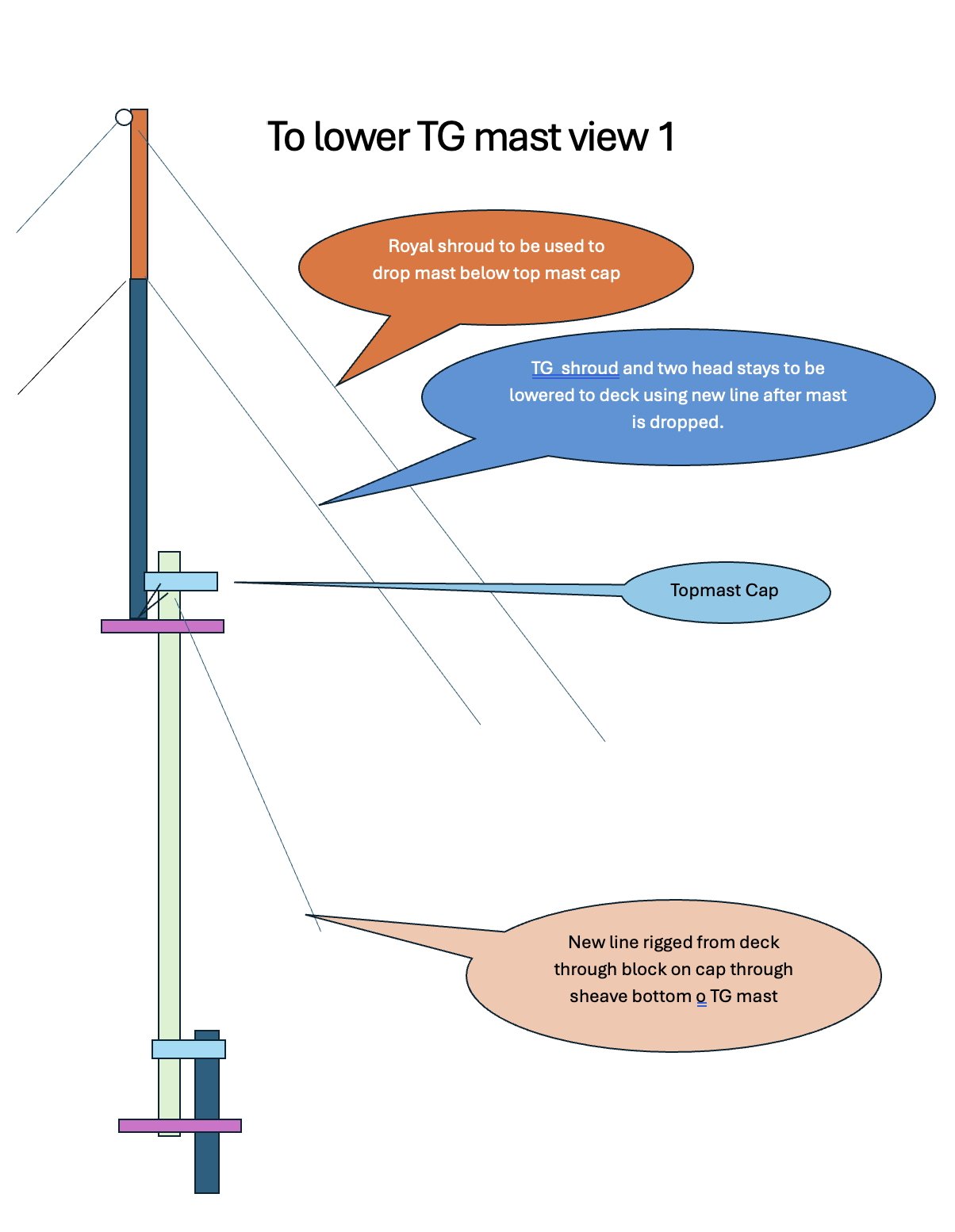
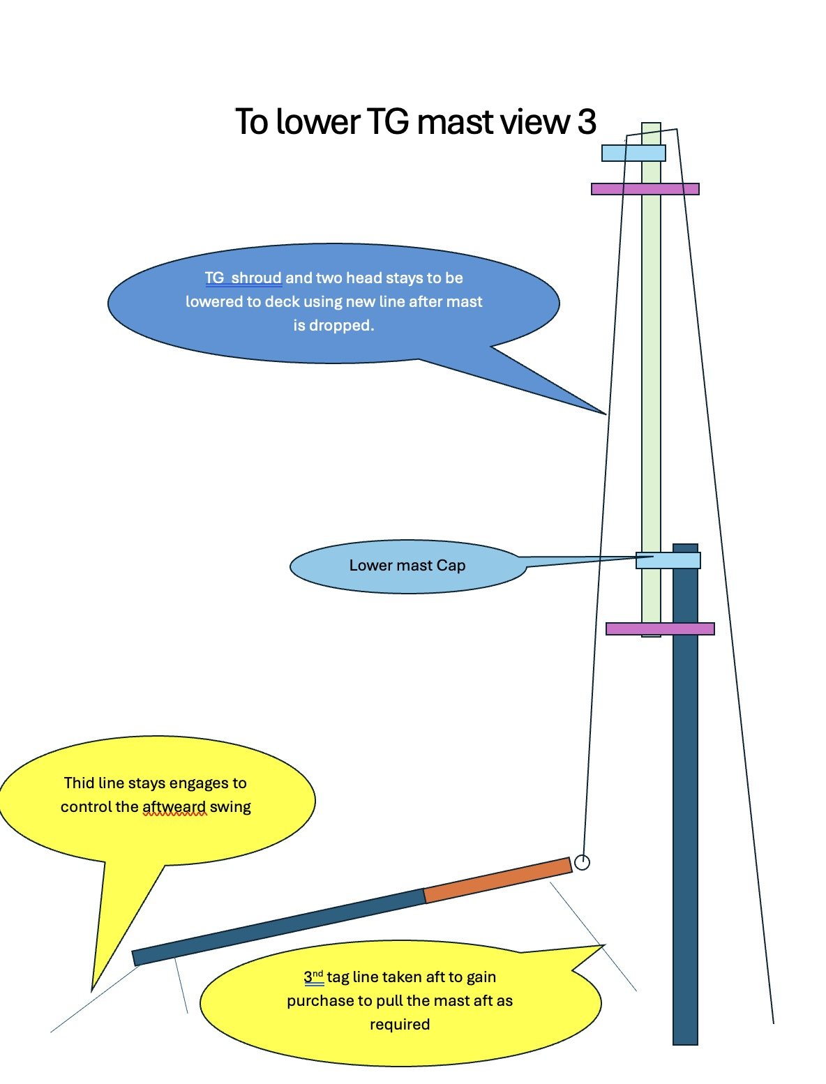
14 the masts are to be coming down….we hope. This post is just to explain what I am showing. I started off by completing all the rigging here for the topgallant mast and then taking it away as the mast comes down. The mast must fit through the topmast cap, so a little more sanding on the small built-up transition between top gallant and royal mast was needed. Then, the mast top has a ring to receive shackle equivalents for the top head stay and top shrouds. It had to be “flattened” a bit to fit through the mast cap hole. I had some fun making the following three sketches to show my logic as to how either the main or the fore topgallant masts come down. The following steps are my approach to how this mast was dropped whole at sea. View 1 • Rig a new line off the topmast cap through the fid to a block on the starboard side. [ a bigger mast like the topmast would need a block on both sides] This line drops the mast as long as part of it is guided by the upper mast cap. • The topgallant head stay and shrouds have loops that come off just as the top of the mast passes through the mast cap. These are tied off then lowered one at a time using the jib halyard or after the mast is down, the line that is currently dropping the mast • [ My idea to avoid rigging a second very long line] The one side of the royal shroud is pulled up and lashed to the ring at the top of the mast just after it go through the mast cap, but before it drops below the topmast top. Assume a similar snatch block on the side of the upper cap. This line will take the load and the “ new line “through the fid below will be released. View 2. • Two tag lines will be attached to the bottom of the mast as it passes the lower mast top. The fid hole line goes forward to a snatch block on either rail chosen by crew, just aft of the foremast shrouds to pull the bottom of the mast forward. The second tag line replaces the halyard currently going through the mast sheave, once the top of the mast is secured by the shroud. This line falls to the deck for the crew to manage the mast bottom. • Once the new line is free from the mast bottom sheave, it is available for lowering the head stays and shrouds. View 3 • The trysail gaff will be engaged to rerig and move the spar into its storage position. It is assumed these two masts will be suspended on either side to the fore and main masts to allow a tent structure over the main deck to last through the winter. • The main topgallant mast is almost perfectly located when it reached the deck. The fore topgallant mast must be rigged and hauled aft more than its full length for storage. On the model, • the main topgallant mast has just fallen below the mast cap. A tag line will be used to position the mast bottom for the exchange of lines as described above. • The fore top gallant mast is nearly down and the first of the shrouds is being lowered. On this mast there are two Jib halyard that could be used for part of the effort I assumed though one line at a time I have engaged one that is lowering the topgallant forestay. • I show two of the shrouds already coiled and ready to go into storage. Considering their large size, I image they might have stayed on deck. • I am not sure they will start both masts at the same time. I chose to show that process considering the huge size of the crew…64 men. The more critical fore mast is nearly down, po perhaps the topmast crew would shift to the main and the deck crew would complete the first mast. 4,5,6. The three Photos show the various connections for the fore topgallant mast as it is displayed. just a note; in view 2 the lower tag line was passed thru the fid hole. the upper hole is now empty that had the "new line from the ast cap to lower the mast for the first level. that tag line will be taken up by crew members when I add them later. the lighter weight royals shroud d coiled on deck and wrapped on the windless is feeing up and lowering the topgallant mast. If I am totally wrong this would be spare line. just a very long one.😄 so I am not an expert but I really enjoy trying to figure things like this process out. I am back working on the rigging adding line after line after line....... cheers


- 62 replies
-
- 4
-
-
- Arctic Exploration
- OcCre
- (and 2 more)
-
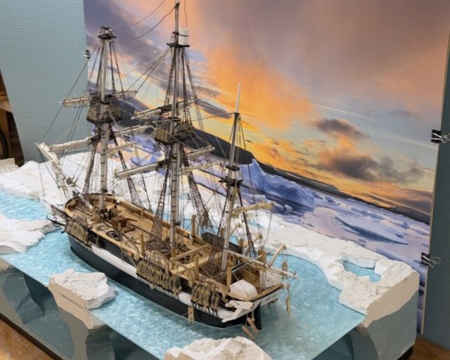
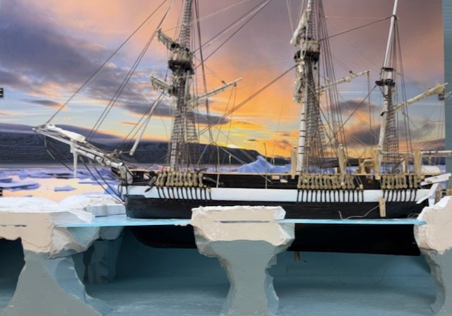
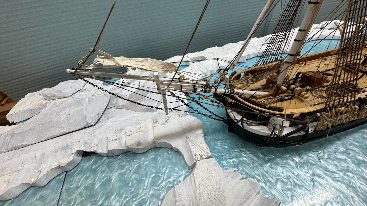
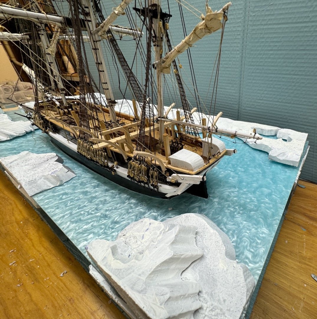
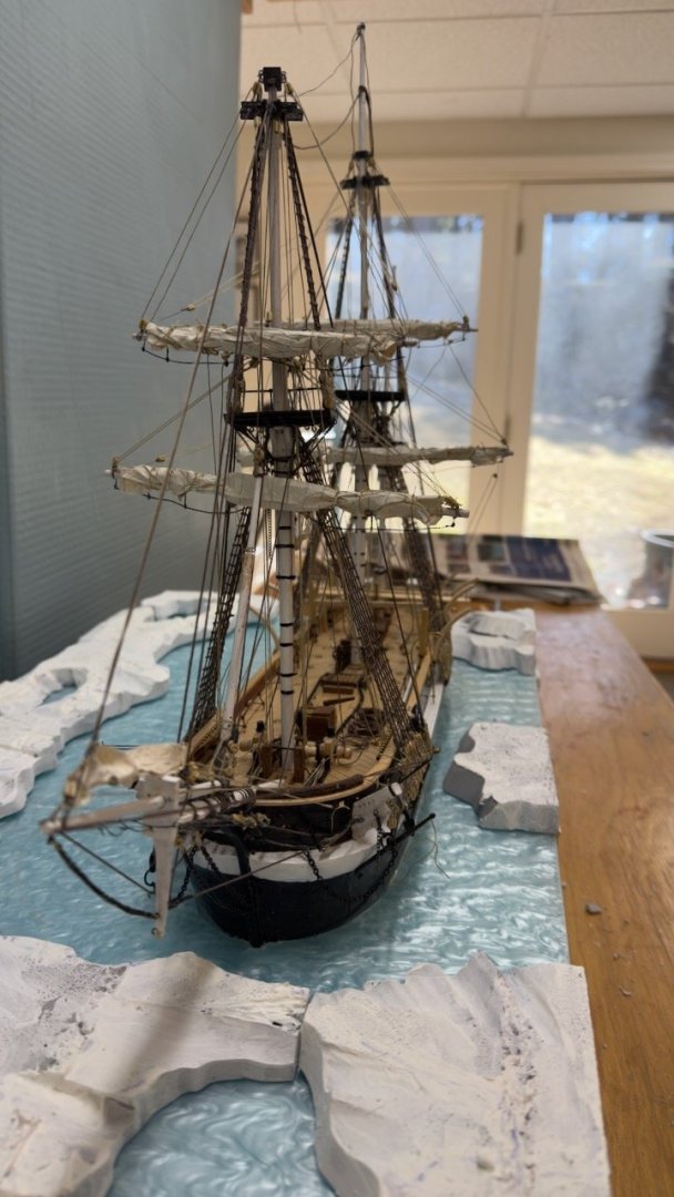
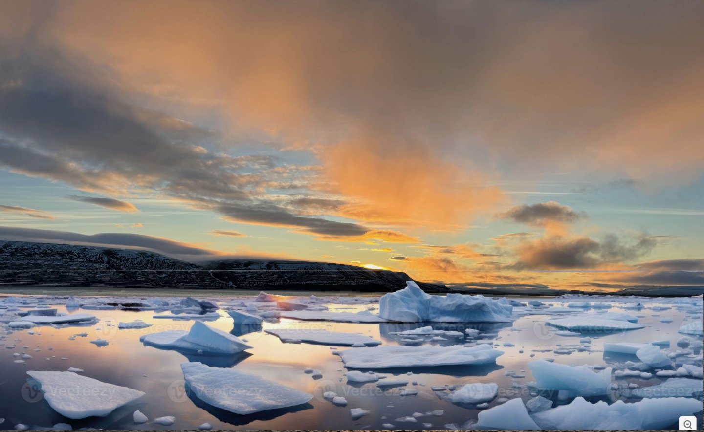
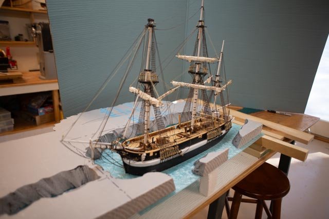
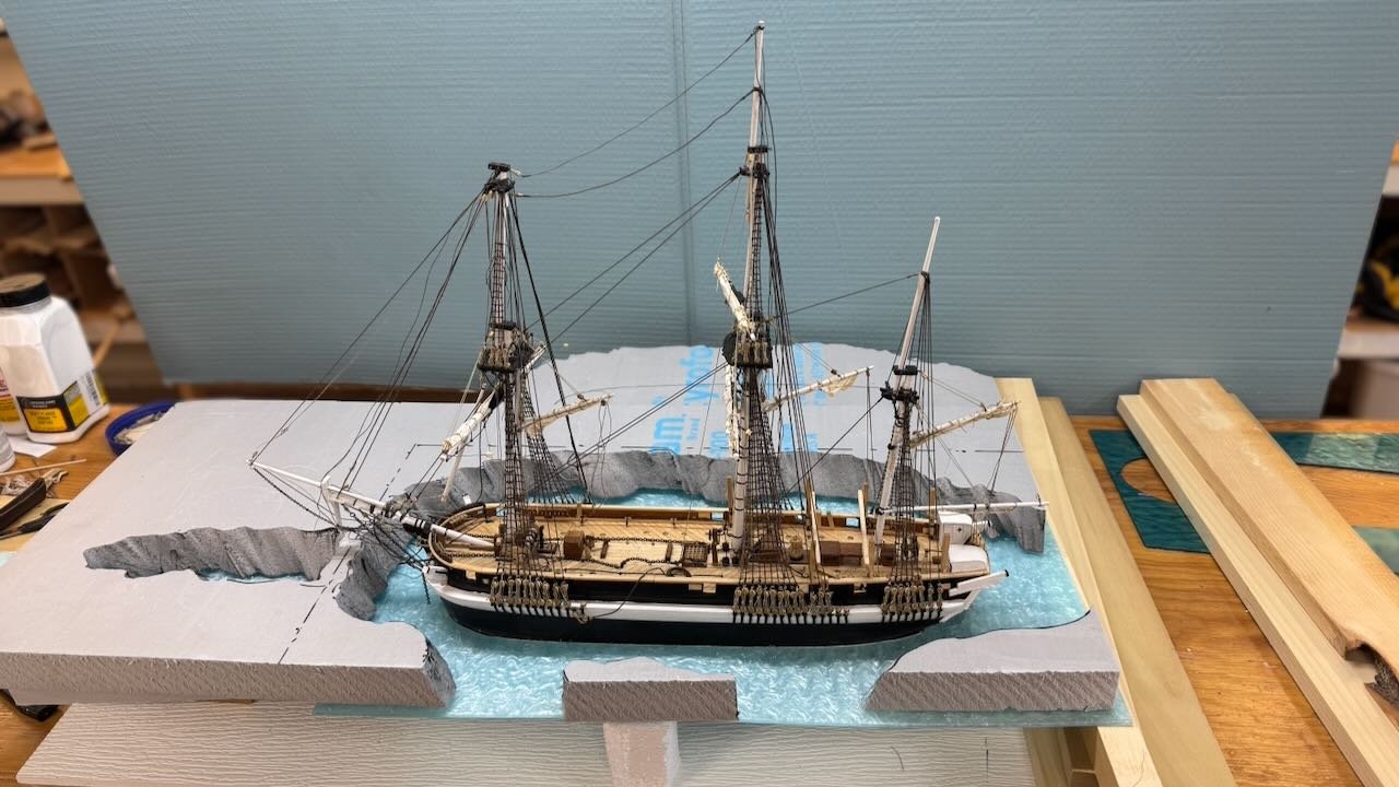
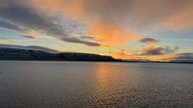
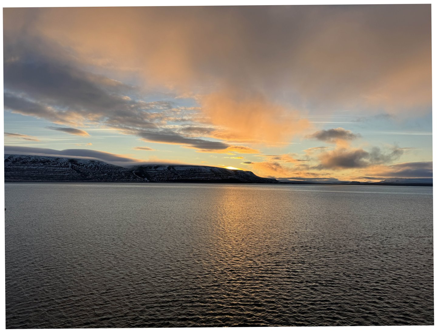
13,3 to finish up with the " starting of the diorama" here are some images taken before we run south for a week on a beach. Hopefully all our remaining snow will be gone when we return. 15-17 three views from above. Still pecking away at the rigging and deck work 18-21 four views showing below and above the ice. There is a lot of work to do to make this work 22 here is the preferred back drop. A sunrise photo I took at Beechey island with and internet cropped image of arctic ice. I hope I can make this one work as the day time image is not as nice. When I get back I will order this poster and mount it behind. My fear is the coloring, as nice as it is, will not blend nicely into the acrylic and ice.....we'll have to wait and see.. cheers


- 62 replies
-
- 4
-
-
- Arctic Exploration
- OcCre
- (and 2 more)
-
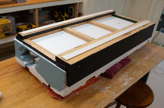
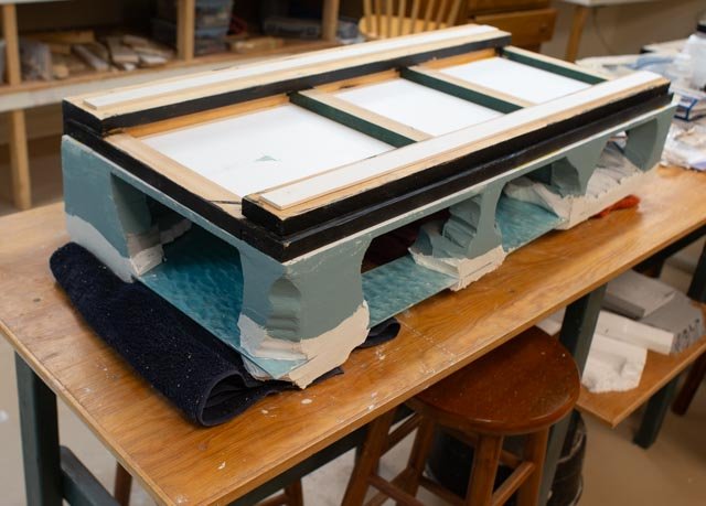
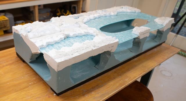
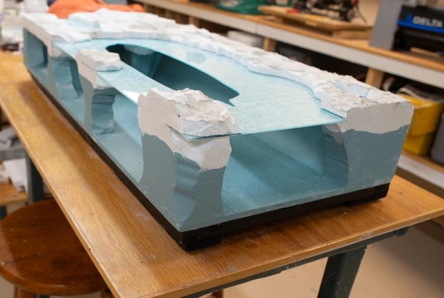
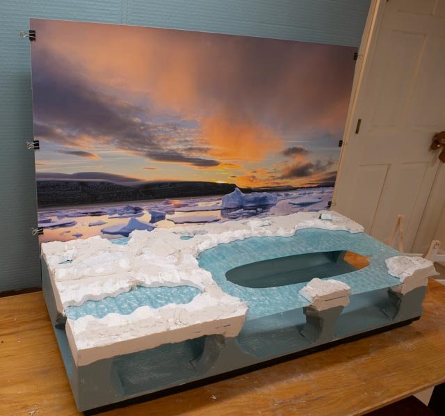
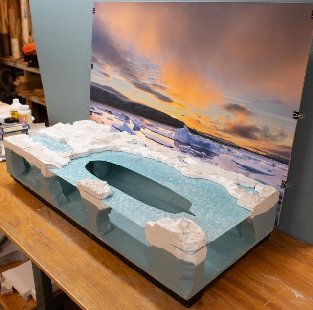
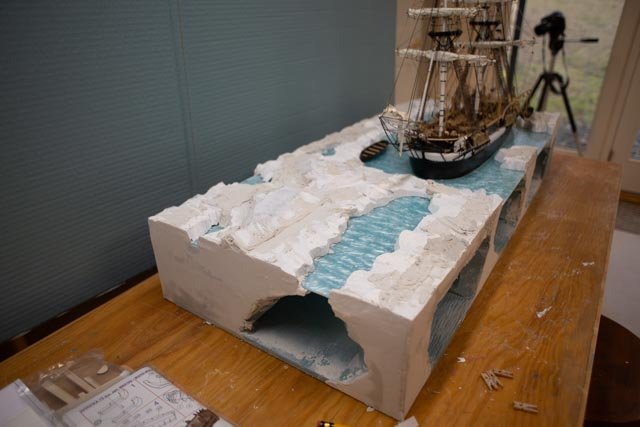
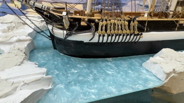
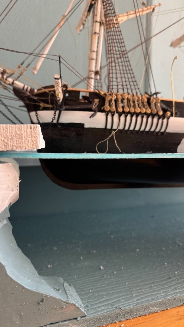
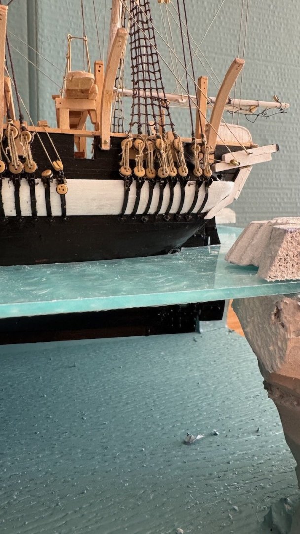
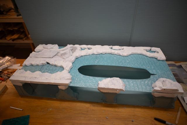
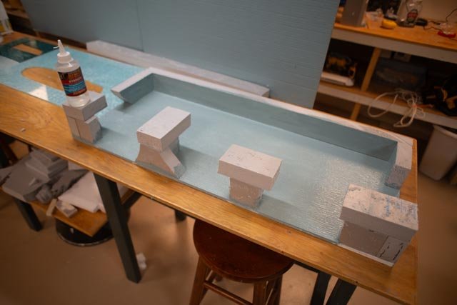
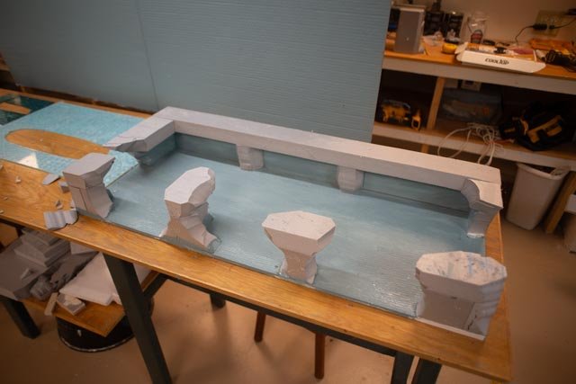
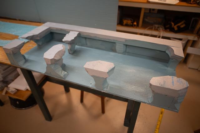
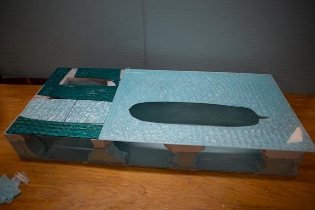
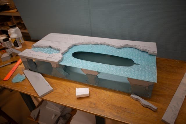
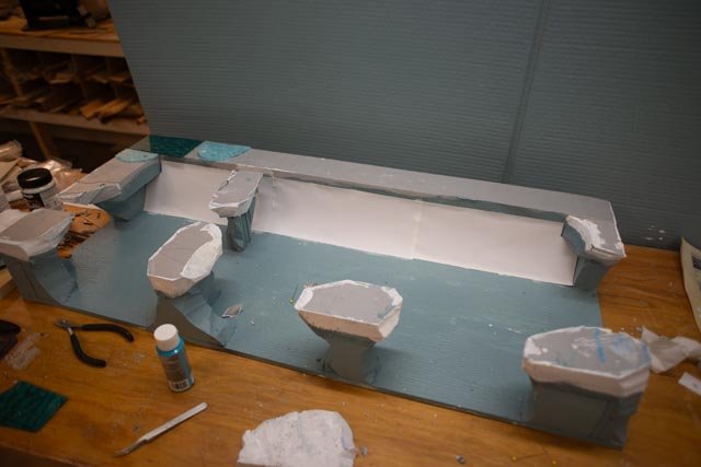
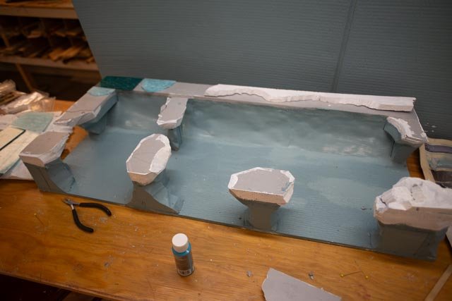
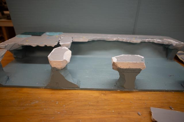
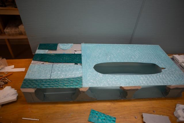
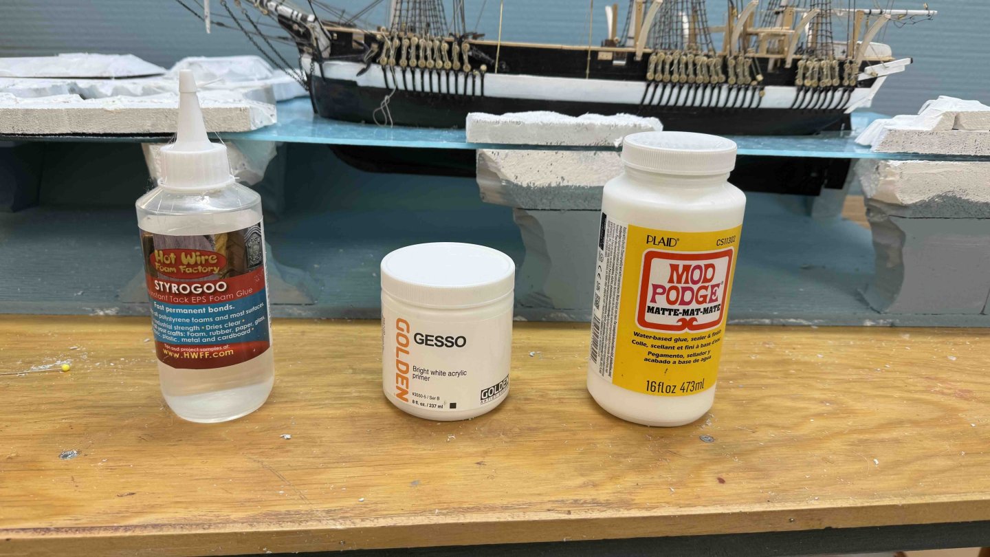
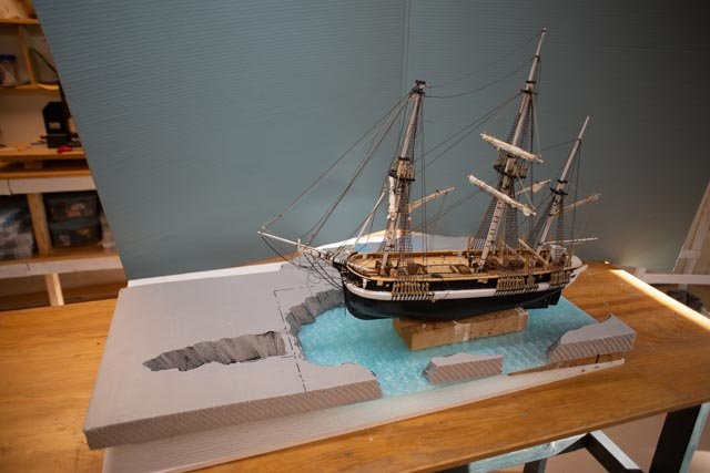
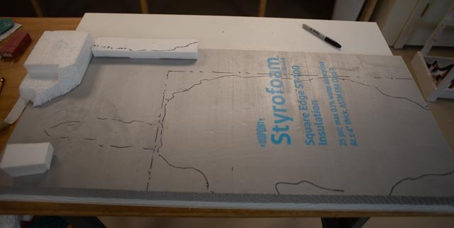
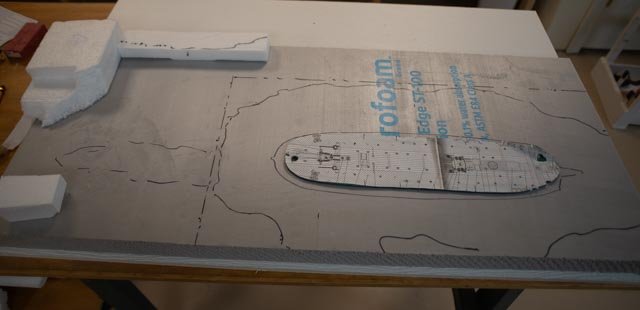
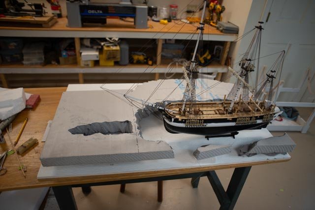
13.2 starting the diorama Since the preview earlier this month I have been experimenting and buying a few things that I may or may not need. I am about to disappear for a mid-winter break, so I need to pull together the progress with an update. The next series of photos show my trial and error and adjusting as I work into this area of trying to make ice look real.. I have taken a photo after each step. Here we go 05 -06 set the base elements and glued them to the base. Then I painted them all blue and set up the front elements in massing only. In the second view I use the wire cutter to shape them. This is first pass. There are competing elements. On the one hand we must support the water [ acrylic sheet] and the other we want lots of visibility below the water. 07 here I added intermediate supports and painted the back which is hopefully intended to be infinite water. I am not happy as the supports on the back are too visible, and one sees shadows. 08-09 I set the water on to help plan the other ice. I cut out sheets and primed with Gesso ……. Note I am using the model cut out to extend a lead forward. I then set the cut-out ice on top. currently, I need to plan the underwater ice as well. the protective film is still on it. Painting 10-11-12. the sharp corners of the blocks on the back wall of water were not convincing, so I took card stock paper and using mod podge glued it in place then painted it blue to hopefully look more like infinite water. The thin long loose piece on top is painted out to be under water ice. In the third image it and another piece to the left side are pinned in place. Once I am happy with underwater painting I will glue and pin them in place. 13-14. Here I laid out the acrylic. I am using scrap from the mock up piece so there is an even layer across the whole build. The last view I have the ice in its current preliminary set up. The is much more to do with that stuff but here is a chance for a breather. 15. here are the three products I am using so far • Styrogoo to glue the Styrofoam to itself and the base and the acrylic • Gesso to prime everything except the paper and pvc baseboard • Mod podge is the glue going forward as I add stuff to improve the ice. Fill slots in the water blocking etc.. All for now I will add the vessel and look around tomorrow.
- 62 replies
-
- 4
-
-
- Arctic Exploration
- OcCre
- (and 2 more)
-
Bob I am always happy to find another build that relates and adds background to my attempts. I had read about Astrolabe in passing while reading the book…The Explorations to the Antarctic Peninsula by Hugh Allan. I was reading it in general interest but more to find who was there around the same time as HMS Terror and Erebus. In reading other books it was understood that the British Ross expedition was expedited because of the your new fried Capt Dumont, the French, Americans and others all headed to and claiming land in the Orkney and other islands in the 1830 era. The corvette Astrolabe nee Coquille, along with her consort Zelee was apparently stuck in the ice for a week and there are images I am sure you have seen. Anyway, as the story goes their purpose was more focused on the overall French interest in the South Pacific and they were apparently quite successful. Also, just to sail into pack ice and escape is no little thing. Any wooden vessel going around the world, she went twice, says alot about her. I look forward to dropping in from time to time. I am also sorry there is no short cut around all those ratline hitches. I decided to think about it as knitting a sweater. Something I could not do very well, I am sure. My solution is I never did too many in a sitting. Cheers
-
Kieth and Bob, thank you both for your encouragement. I will soon be off in a new world of making ice. Waiting on glue for styrofoam at the moment. Bob. welcome and thanks for showing me another wonderful and relevant build to follow. Astrolabe seems amazing and I will flip over there with more comments about the book. the Exploration of the Antarctic peninsula by Hugh Allan. It is an fast read through some 30 expeditions between 1819 and 1937. Your captain was number 15 and James Ross leading Erebus and Terror was number 18. if you are like me and read too much, it is a great addition. Leave it to say that Astrolabe's cruise to the Antarctic was a key element to expedite getting both Erebus and Terror set up and ready to sail in the late 1930"s. cheers
- 62 replies
-
- 1
-
-
- Arctic Exploration
- OcCre
- (and 2 more)
-
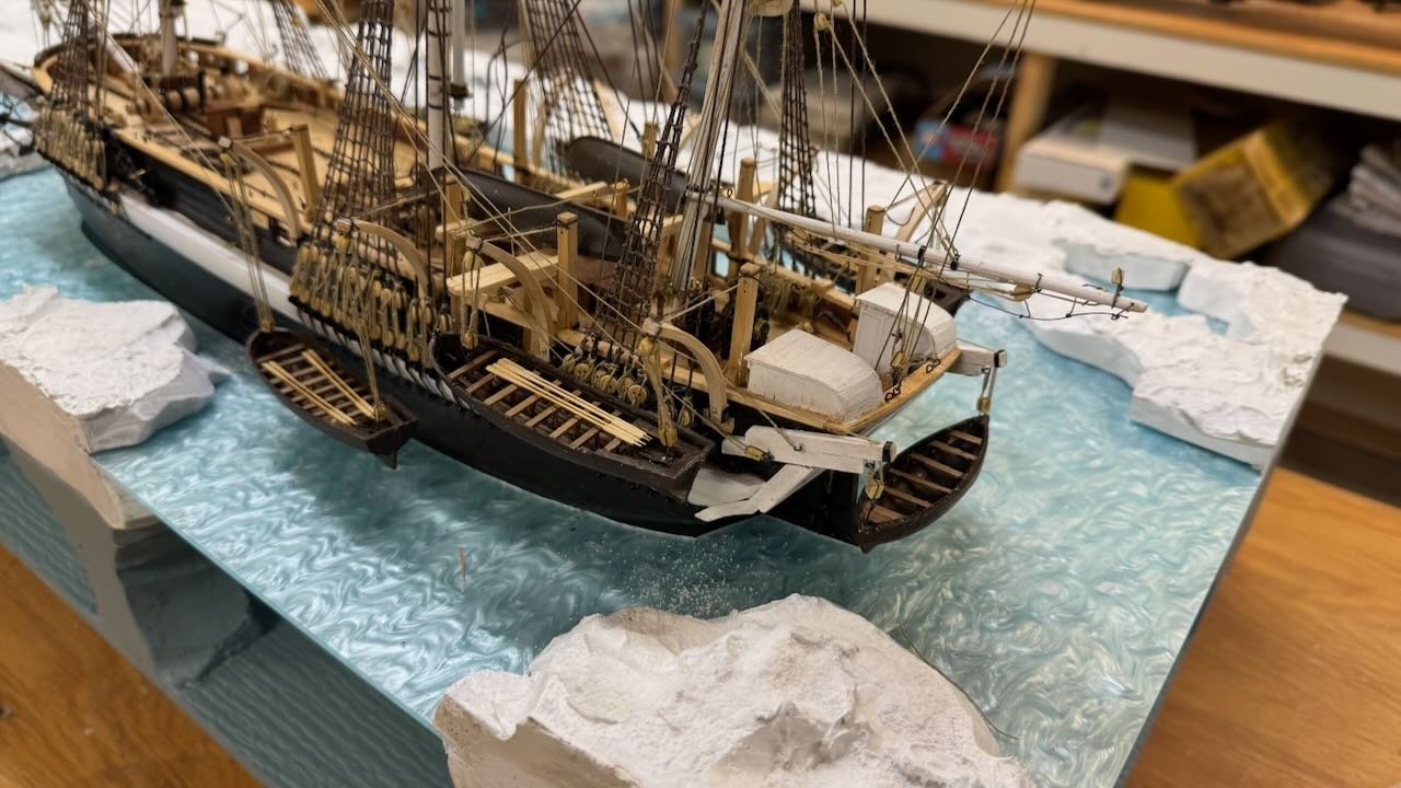
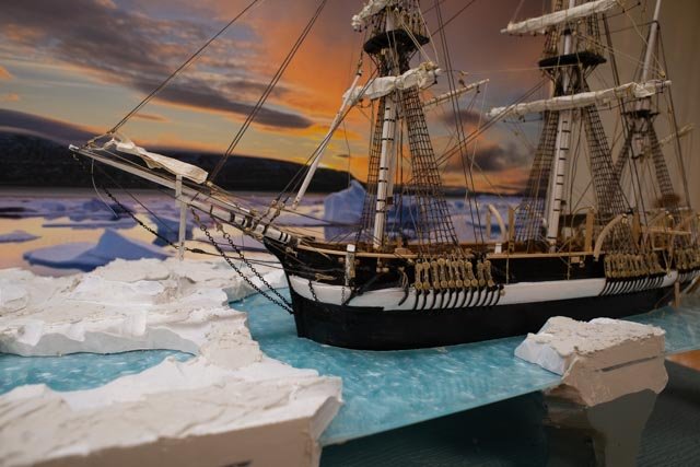
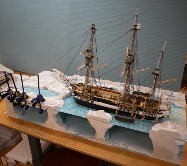
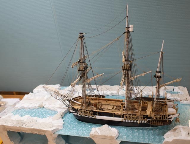
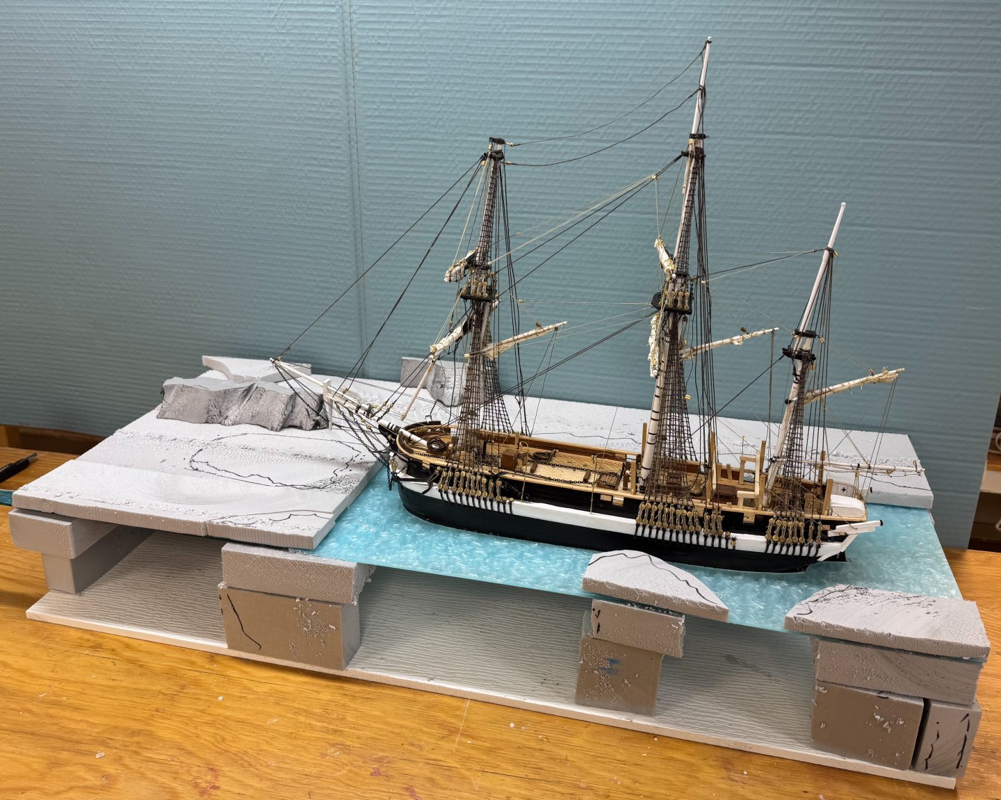
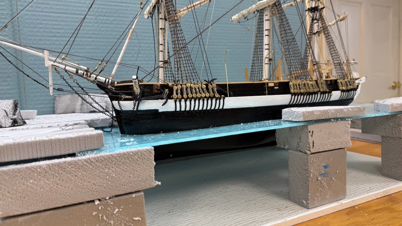
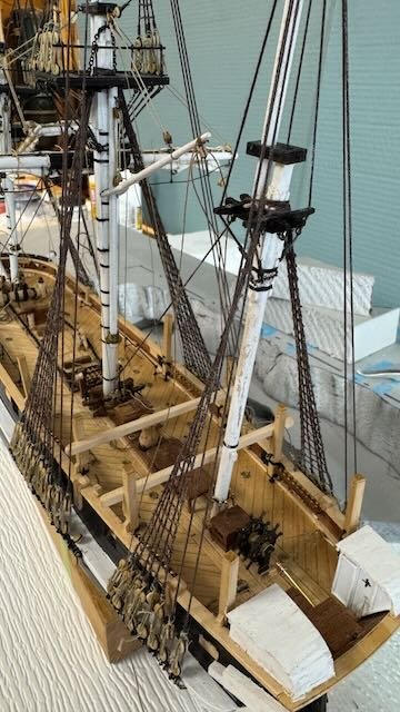
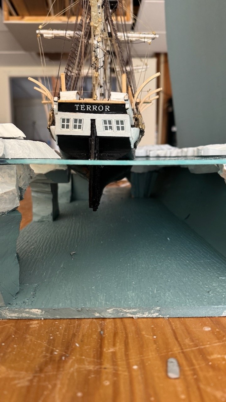
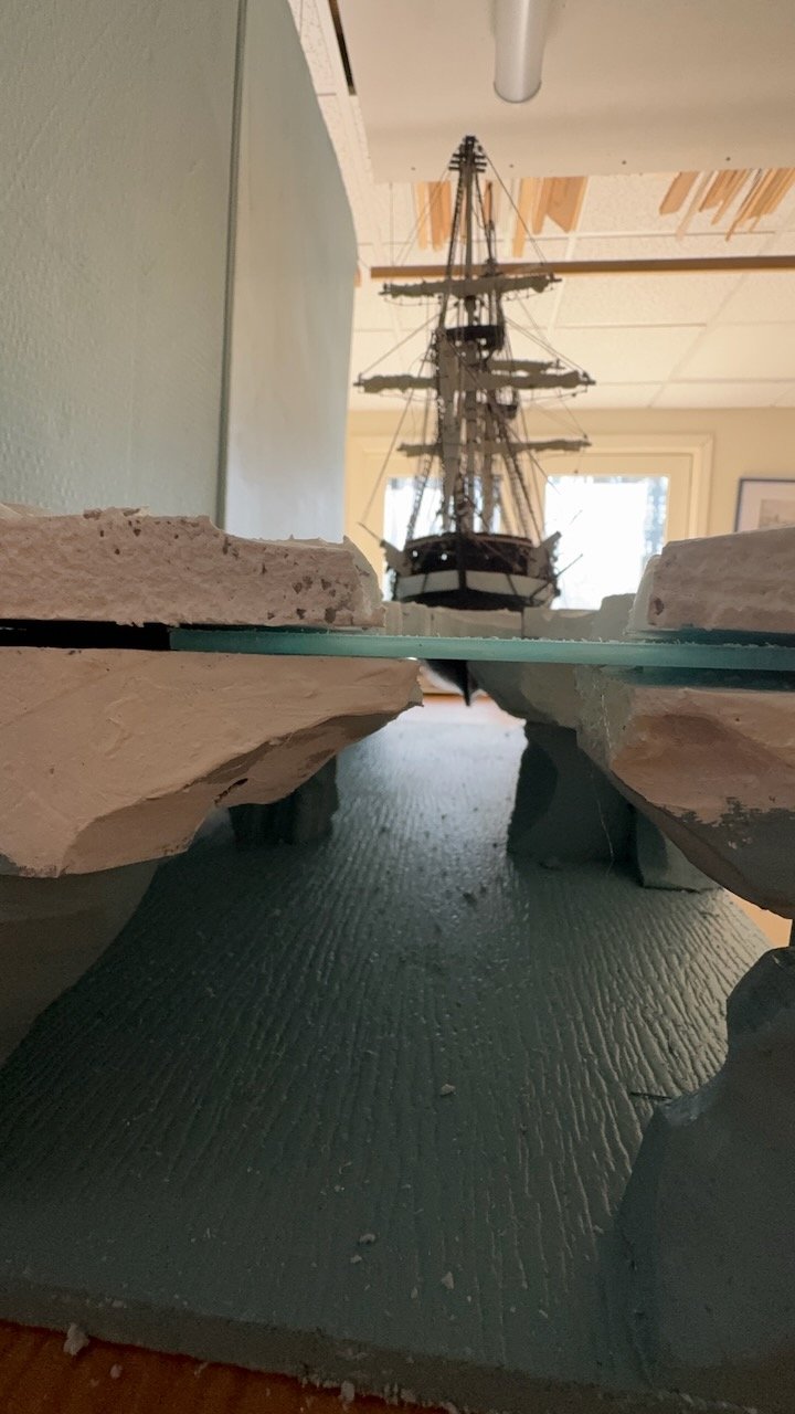
13.1 sneak preview step 1 diorama these four views show Terror sitting in the diorama just to show off major massing..... step i I sliced and cut styrofoam to make up the general massing before using the cutter wand and wire to cut ice. the next step will be to glue it together without water [ acrylic ]and then carve the edges of the ices. after that step will be all new for me. I also have pieces a little thicker that the above water ice to glued and carved to the underside. anyway it is friday and a good reason to celebrate on the model itself rigging continues as well. cheers


- 62 replies
-
- 4
-
-
-
- Arctic Exploration
- OcCre
- (and 2 more)
-
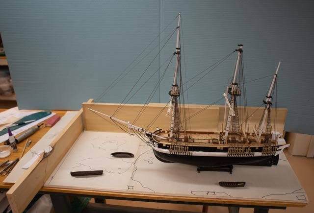
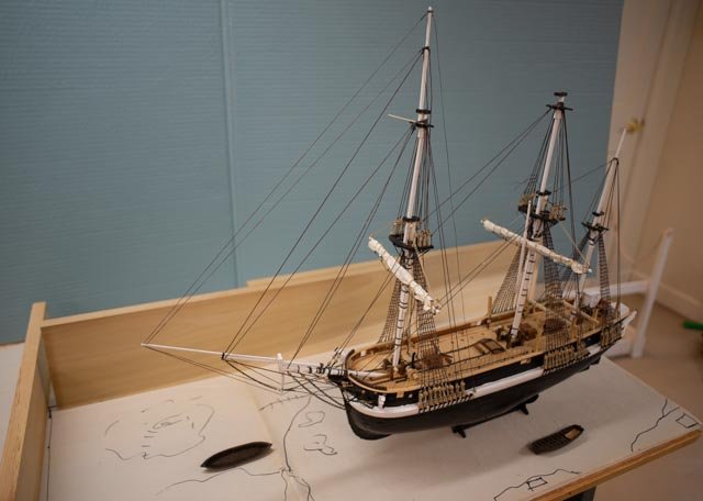
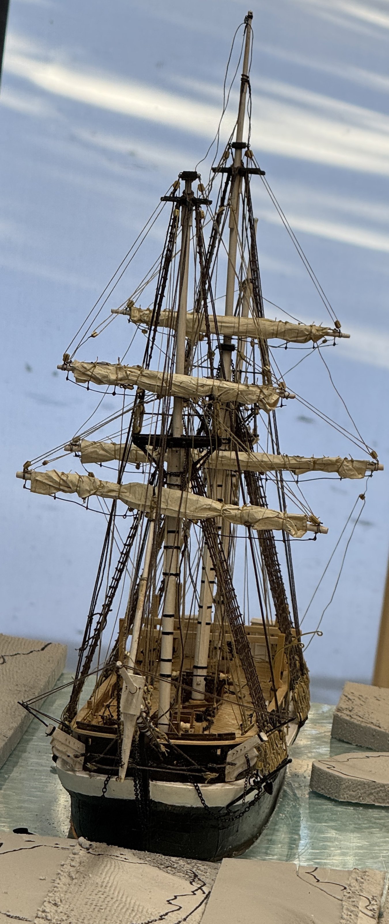
Thank you Keith for the insight and gentle push. I was outside earlier this morning. It is 15 F here with winds steadily gusting past 20mph. The snow is too hard to shovel. After 15 minute the dog looked at me and sort of said what are we doing out here. We could be in the shop!😃 After digesting your comment the light bulb went off. If it were July - August and they we sailing for two days across the Davis Strait, sure push up that extra sail off that extra boom. But by fall it was easily 15deg F and wind often much more than 20 mph, and they would not have that extra jib boom rigged. You and the local weather convinced me....the flying jib boom shall ride on deck in storage. 11-12 for the record here are the last two photos of her rigged [ minus the sail of course} cheers and thanks as always for for your comments...
.thumb.jpg.601f2dcfbba727a3b11c4a842975ea49.jpg)
.thumb.jpg.7925abce2369c785efb3035d18736cbf.jpg)
- 62 replies
-
- 3
-
-
- Arctic Exploration
- OcCre
- (and 2 more)
-
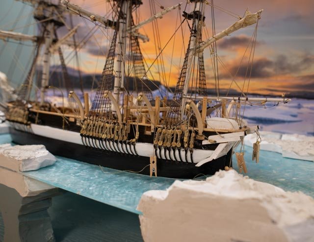
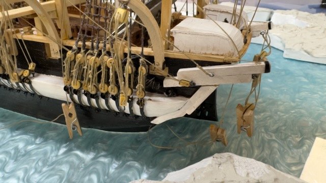
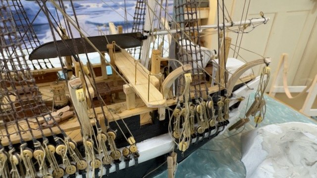
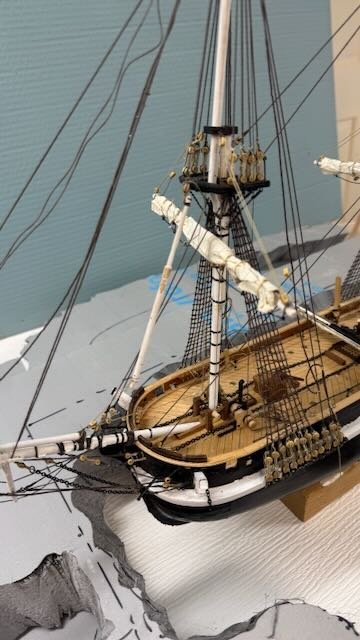
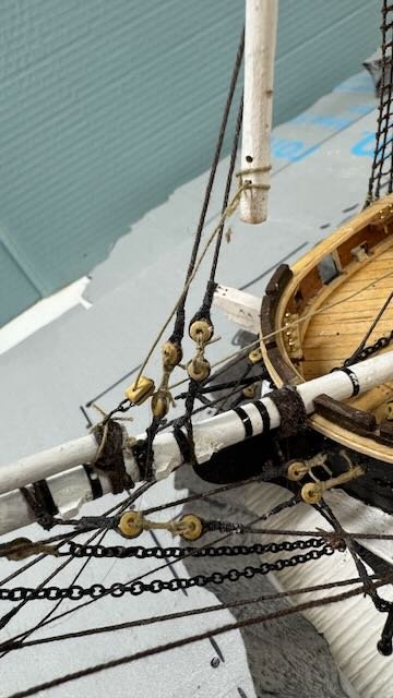
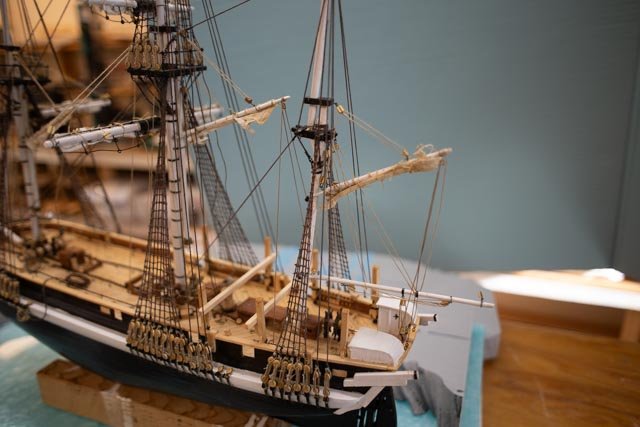
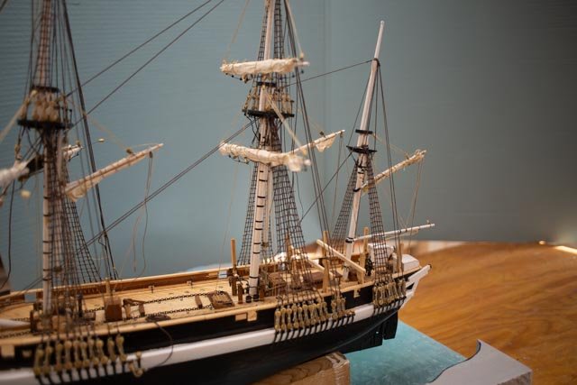
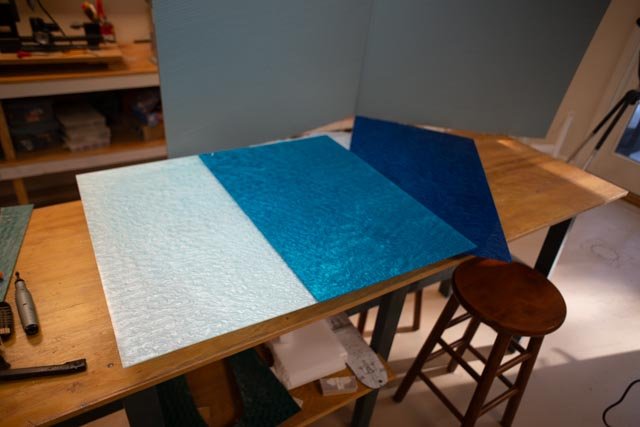
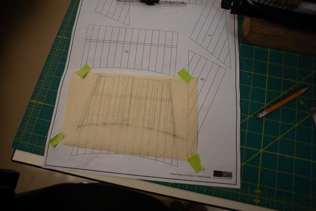
12 first part of rigging I start by admitting I am over my pay grade, especially when showing how things were done 180 years ago. So, for experts out there I am not challenging anything, just sharing my applied recreational sailor’s logic to show the vessel still in the icy water, and the crew removing three spars. In general, I tried to dual task lines and not just add extra lines for everything. I break this sequence up by mast. First however there are a few things I decided as to what the completed vessel would have had going north that affect all three masts. example: I added the fore and main trysails. I choose to include them for three reasons: · First, I defer to the decision of Mathew Betts who included them on his drawings that I understand reflects what he felt represent as the 1845 design. · Second is a practical sense. I suspect the main purpose of these two gaffs was for constant movement of objects on deck. By example, how without them would one load the sledge and then the stacked boats aft of the foremast or again boats on the high racks behind the main mast? · Finally, the need for fore and aft sails to navigate through narrow ice leads. Having been a recreational sailor, I have respect for these guys threading a needle through ice. Also, for ferocious wind changes, these sails were easy and fast to set or close. Useful as a storm trysail as well. As Capt MacMillan of the schooner Bowdoin said in 1920 while explaining why he felt a schooner was the best rig for the arctic. “…You could rig it and change it easily and quickly. In the arctic there is either too much or too little wind….”. Think about trying to maintain steerage in frequent gales. I can’t image taking the trysails away after they were there for over 4 years of arctic/ Antarctic sailing. Yes, there was a new steam engine. Many in the Navy thought they were great and the future etc. I have read not surprisingly that many others as early as 1845 were unlikely convinced. Especially as they only had a small supply of coal. Not enough coal to allow sustained operation…I believe that is from Palin’s book. As to the bow sprits, I am not so sure I am making the right decision here and I may change my mind. Unfortunately, Betts did not consider doing a sail plan. His two drawings for the spar plan and standing rigging leave a lot of questions. So, as I have recorded, I changed from the kit design of one long sprit and one jib boom. I shortened both the sprit and the jib boom and added a long flying jib boom. I have no reason other than Betts drawings. However, without a sail plan I see no evidence of a third [ flying jib] foresail. The only reason for the flying jib boom seems to support the royal mast even though the artwork shows no such sail was set. Way over my paygrade to say or think any more for now unless someone produces a sail plan. To work 1-2. in these 2 photos we see the two trysails furled to the gaff and both a downhaul [vang] and the single blocked line for handling movement on deck. I suggest they may have added a block with multi part lines for easier leverage in handling items on deck. I may add one myself if there is room to do so after setting up for lowering masts. The three spars to be moved into storage, weigh between 350 and 500 pounds and tackle would have been necessary. Starting the Mizzen Mast: · I followed the work of earlier builders, bloggers and used cross trees and no upper royal mast. I read they were using all those British Admiralty standards and just followed as best as I could. The known expectation of frequent gale force winds makes those high sails less useful and dangerous. Also, the artwork showing them sailing away from Disko Island had no royals on any mast, so that layout makes sense. · I am not sure what one calls or the function of the flat vertical planks on either side of the banded lower masts. Please note they are not on the Betts mizzen. · Then after much thought, [and I may be dead wrong here] I chose to remove the composite rings and side planks. The mizzen was small enough [ similar to the big schooners we built here in Maine up to through 1930’s.} they needed to have hoops for the sail, so they would most likely have been a solid piece limited in diameter accordingly. Otherwise, there would have been a Spencer mast [ identical to the trysail masts] like larger barks and full ships. I unfortunately did not think this through early enough to include rings and chose not to disassemble the mizzen to add them. I needed to scrape and sand up the mizzen after removing the “side boards” and chose to leave it rough. Later, after say 1860 all the USA big schooner masts were dark brown due to aged oil or grease etc. added to the masts for smooth movement of the hoops. This mizzen could possibly not have been painted white. I stop here in deference to my lack of British knowledge. I left it roughed up and did not repaint it. · 3-4 here we see my first go I furled the spanker on the boom. This too would have been Yankee doings as the sail would have been lashed to the boom. I say looking through others’ work that this sail was loose footed. Therefore, I went ahead and redid the furling to the gaff. The second image shows the rough mizzen mast where hoops would surely rubbed off paint. Before completing the mizzen, I need to share a surprise as the acrylic sheets from China showed up in days, not weeks. Etsy was my source, and they sell them at the size I wanted in groups of 6. I chose 2 each of three colors. They are not textured, but I can deal with that down grade. 5-7 here we see three colors in the first view, a dark ocean blue , and very light and I hope icy blue and a mid-range sea blue. I chose the icy blue, and with a larger 16 by 24 size sheet I moved things around a bit. I then used the previous cut out as a template and got what I hope will work out …..icy toned water beginning to freeze. Back to the mizzen and some of my moves. 8-10 I respect the other builders of this model who are more familiar with British Navy standards etc. I have over the years collected a parallel library of America Non-Navy standards. My example is all the work by William Crothers. I would guess there are more similarities than differences but leave that discussion for the experts. In my build, the combined topping lift/lazy jacks, the life lines, the out haul, the boom tackle[ preventer] are all from my New England approach. I have to admit I just went ahead building them that way and then looked at other builds and said oh no..I am wrong again. These three views try to capture the spanker fitout, then the boom detail, then the upper mast. At this point only one block is there for the topsail. I am debating when to add the flag and how to soften it. New up the main Cheers
.jpg.64b91598437b40d4672e7f691a9007b7.jpg)
.jpg.37f6b518d444dda617f1f00509900ce7.jpg)
.jpg.c74166c24623f12ad51277301b8c03c6.jpg)
- 62 replies
-
- 4
-
-
- Arctic Exploration
- OcCre
- (and 2 more)
-
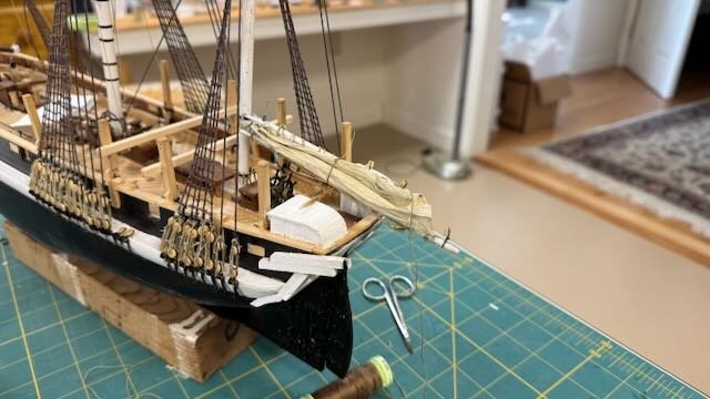
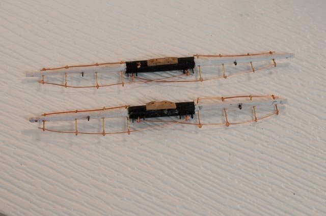
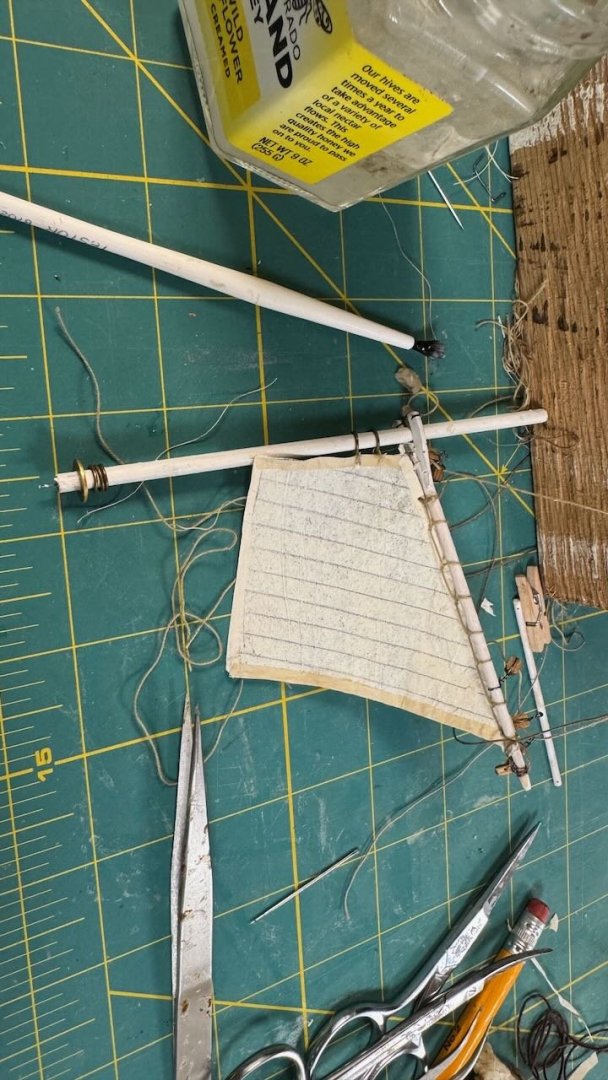
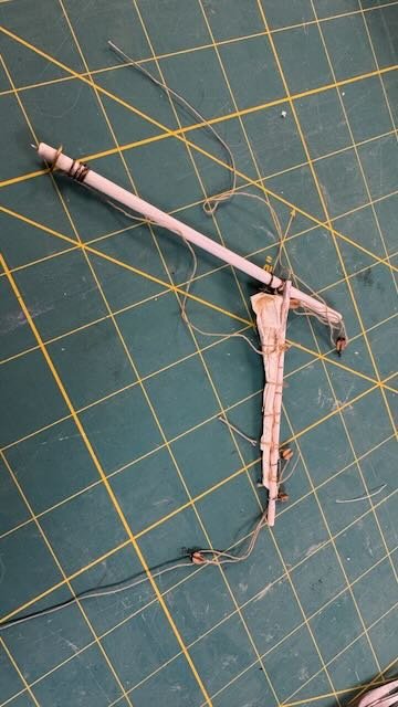
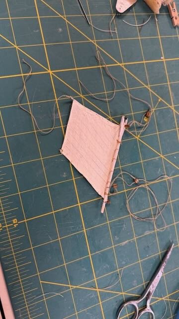
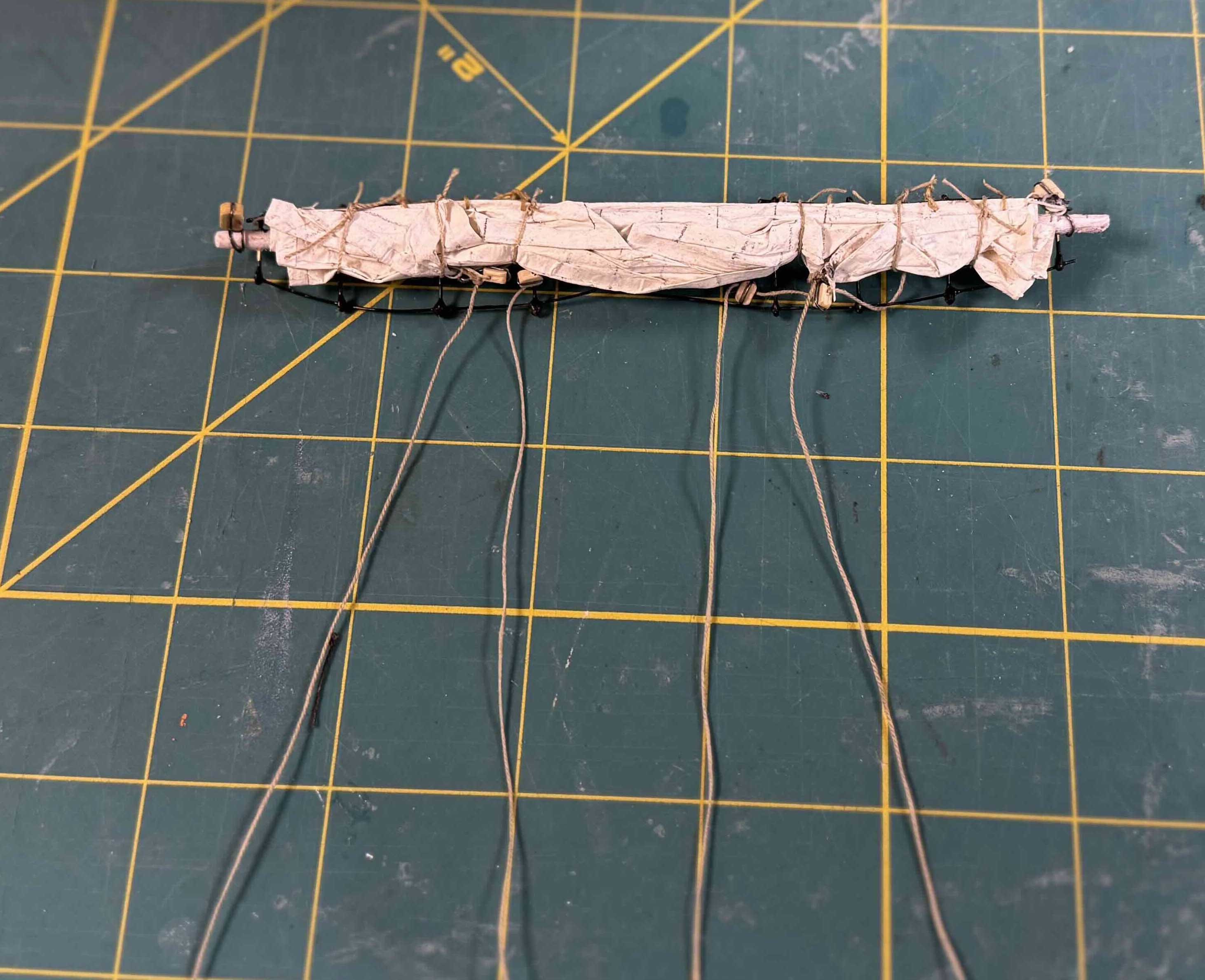
11 back to the rigging let’s make our sails There are many U-tube series that help with learning the various processes here. I recommend ones goes there. I share my process more to encourage others to give it a try. I am no expert. I usually do full sailing models, So, what we see here is a bit of an experiment. I furles three sails on the Bowdoin and that is the extent of my experience in this process. 1 To make up the yard arms I chose to use copper wire and brass leads. I did not blacken it as that requires two processes and I often have residue that rubs off. That cannot happen with these delicate sails. I used paint, and it really gets covered up with the furling of the sail, so I don’t feel too guilty. 2 here when copying the design onto tracing paper one needs to sure the sail will nicely fit on the yard arm. I say this here a second time, because it really happens…. they seem to grow. Also, I read somewhere that if sails are to be furled, one should only make them about 2/3 their full size. 3 here markings on the silk span are cut out and ready to turn back the edges on one side. I stretch light line on three sides and heavier line where the sail is to be sewn to a spar. 4 -5 the strings are taped down and the edges turned back using diluted white glue. After drying the sail is flipped and thin strips applied to the back side [ reef line too.]. Pencil lines are on both sides. 6-7. here all the lines are attached, and the sail is ready to be attached to the yard arm. Finally, we brush water on both sides of the sail and lightly flake it back and forth up to the yard. Then tie loops and let is dry. 8-10. here is the same process for the two try sails. I had to make it up a bit as I have no info in either the kit or Betts book. The whole assembly is prepared. I tied off two rings before furling and left the other rings loose. As this boom would have been very active, I assumed the looseness of no binding rings made sense. They would drop the gaff , shake out the sail and re tie off the hoops when ready to resume sailing next year. Also, I saw little hope in not taring stuff if I tried to install them all then furl. There is no strength in wet silk span. I am now in mid stream for figuring the how to present the story of taking down top rigging, I will share that phase in parts All for now

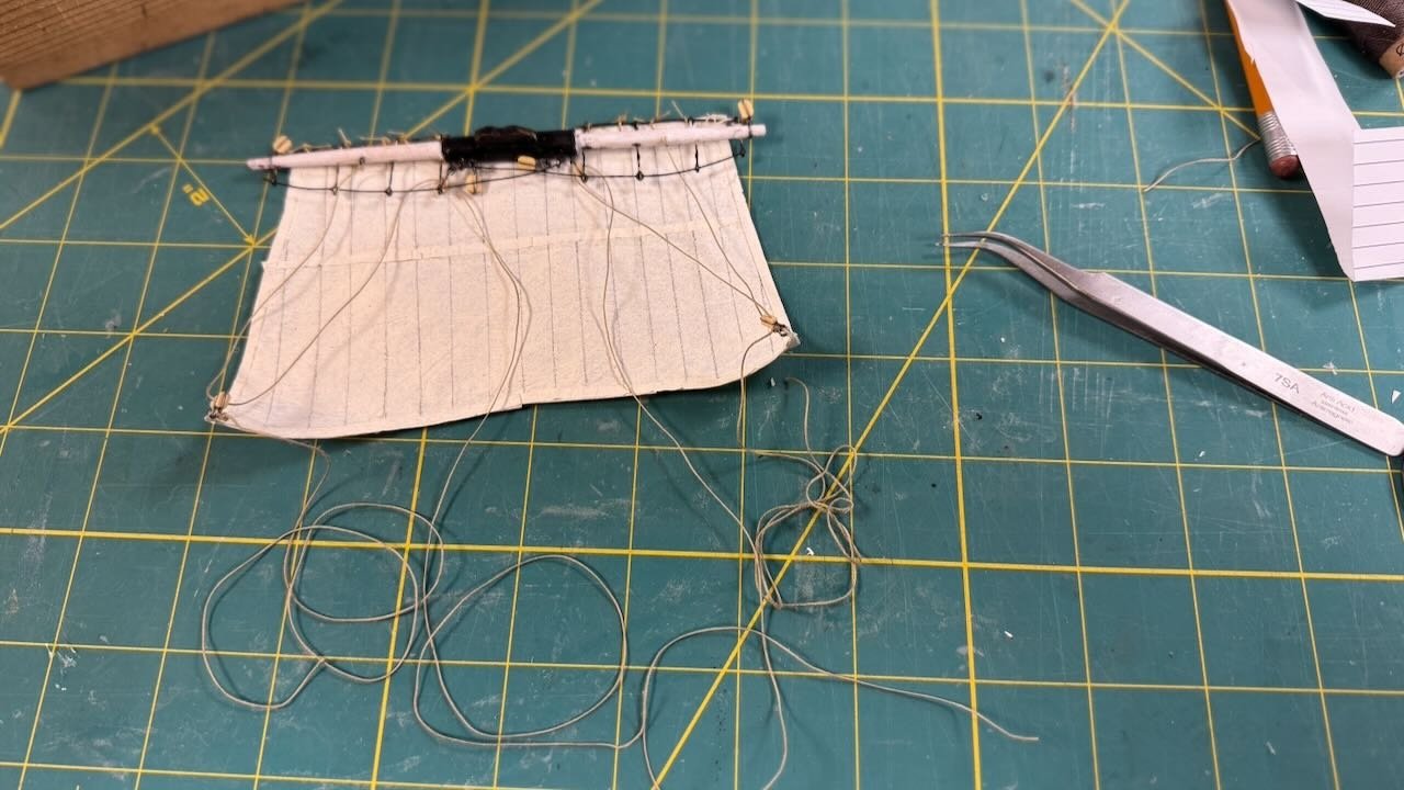
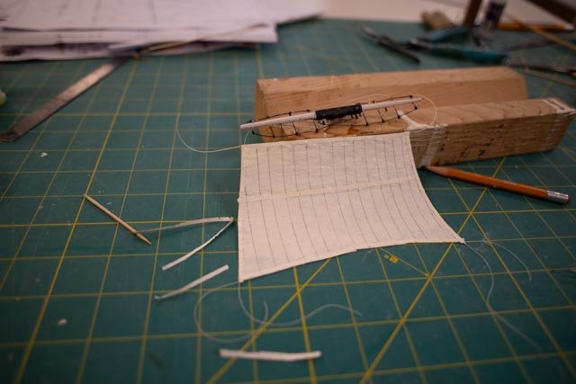
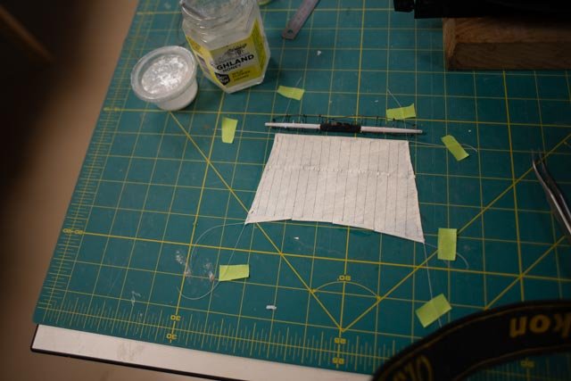
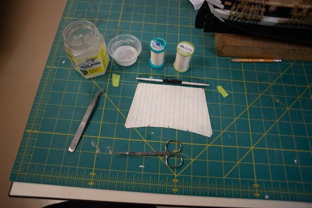
- 62 replies
-
- 3
-
-
- Arctic Exploration
- OcCre
- (and 2 more)
-
wow. thank you for your kind words. I sure hope the diorama comes close to your expectations. I got my new acrylic today in three different color selections, and i think is will work well. More later but here is a sneak preview. there still is so much to do that is pure modeling as well. cheers
- 62 replies
-
- 4
-
-
- Arctic Exploration
- OcCre
- (and 2 more)
-
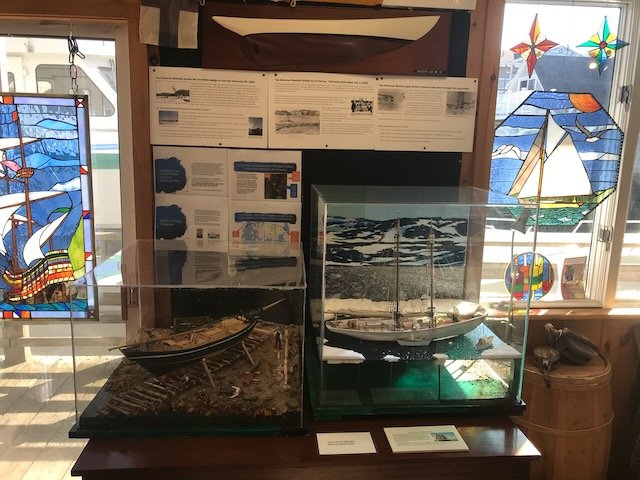
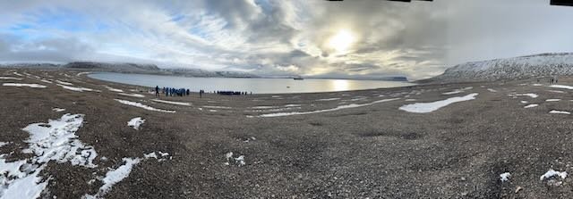
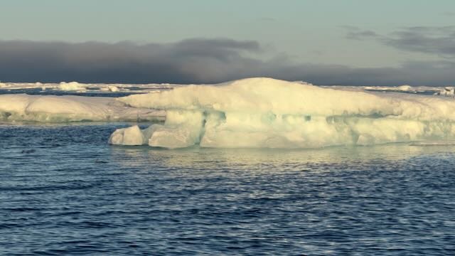
10 cont’d… the diorama is now sort of planned As I believe I have zeroed in on what I hope to do, I just want to finish recording how I got there. Much was in the previous 2 postings, but I want to feel I can set off on the next phase and the display concept design is complete. If one goes to the Getty Images website directly or indirectly by simply asking Google for HMS Terror images, one will find several wonderful, documented images of HMS Terror. Note some were colorized…Kind of nice. I believe from their notes, and a few other sites that have similar or even the same images, that these images for the most part come from the crew on the Hudson Bay adventure of 1836. I see no reason to suggest any different version of winter quarters of just 9 years later. Thus, either sailing away from Disko Island fully rigged, or pinched in open sea ice all battened down are the extremes have sufficient documents for one to follow. Looking at all these images, however reinforces my conclusion to try to be in between the extremes. I hope to show some of the sailing rigging being taken down for winter. So, let’s see the general shape of our stage. Views 14-18 show the progress to make a ‘stage’ including lay out for the cuts for the ice to allow us to be afloat but close to the ice closing in. I have a sheet of ½ inch white PVC left over from a project last summer [ building a router table]. It will be the base. The Styrofoam is left over from housework and now is just a mockup. It also let me experiment with the brand-new hot wire and probe cutting tool. The sheet in the photos is 1.5 inch thick, which would scale to be a flat slab, 9 feet thick. From what I saw last summer, multi-year ice floating is easily that thick and thicker. More important though, it is irregular. In the ‘cove’ at Beechey Island today, it is water in the summer and surely a regular flattish slab with encased small ice bergs in winter. Therefore any new in the cove ice before complete freeze up is surely less than what I have currently. Out near the transition between land ice and sea ice, there is surely all kinds of stuff going on. In every book I have read, up through say the 1920’s, these coves did not always clear out. My point is I a truely guessing about what would have been there. I will study a little more before committing to the current thickness for the base of prewinter ice they would have encountered. I may need to get a thinner sheet for that. Since my assumption is there was old ice near and at least partially in the cove, the surface will be more like the multi-year ice that today is only found offshore. The point to make at this stage as the HMS Terror will be afloat surrounded by ice. I have ordered several sheet of textured acrylic. I am a little nervous that in today’s market, it ships from China. I hope all works out. I also ordered several items from craft suppliers after watching several u-tube series on making ice. Finally, we get to the backdrop. 19. here is an image of my older Schooner Bowdoin diorama. For the Bowdoin diorama I found images from our local Historical society that showed the Schooner Bowdoin in the actual cove exactly when I was depicting her in the summer 1924. I then found various ice images online. I made sort of a crude collage to represent the backdrop and then added a spotlight to replicate early morning low angled light. For this diorama I thought after choosing Beechey Island that I should use images that I took there this summer. 20. This wide angle shot from high on the beach, above the grave area, shows the huge size of the ‘cove’ and the wrap around land that creates this area. One history buff’ on our tour that day, with the appropriate British accent commented…. only an admiralty big shot would choose this harbor to winter. One was protected but would have to wait until late into the next year to escape. More important, in this zone of the arctic, on the land side there was exactly nothing to eat. They did apparently shoot polar bears and thought roasted but rare meat for the officers was the way to go. Some scientists say that caused disease as more officers died then crew in that first period up to 1847. 21-22. this image and its cropped version are looking south as we were about to leave the cove. One reason this is a good candidate is it would be easy to find ice pictures to merge with similar lighting. 23 -25 The first view shows a similar view but at sunrise for the back drop I need to shape it ..see the second view. I need to add ice and the lighting may limit my choices. To use last image above that I took from just outside this area the same evening, I have older sea ice…. The other images that I took were all in the evening and would not make sense to combine due to their lighting. To pull this idea off, I need to learn a new skill. How to use photo shop to combine some images. fortunately, I have some time to learn it. I can always revert to cut and paste as well. So I feel I can close this phase of concept design for the diorama My first choice is to use sunrise in the cove, surrounded by growing ice. the other view of later afternoon is there if I struggle getting ice to look good. It will be assumed the fleet had made the decision to get ready to spend the winter here All for now.

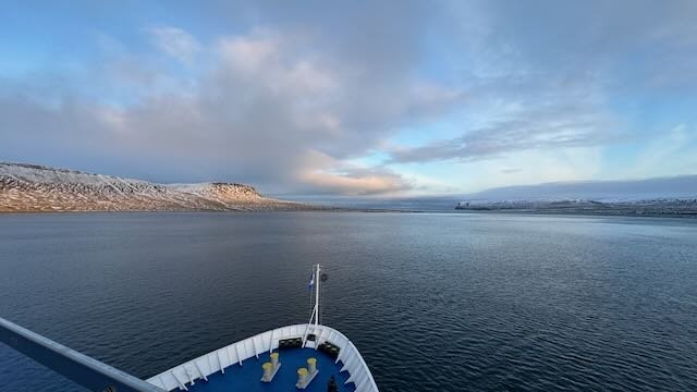
.thumb.jpeg.77e900cc21d709f4e550fbb89633ba16.jpeg)
- 62 replies
-
- 4
-
-
- Arctic Exploration
- OcCre
- (and 2 more)
-
Thanks Keith. I appreciate your advice and perspective. I do not have near your experience as I jump in. I will share some of my references which are different than yours other than Betts. The main example is a Mr William Crothers produced the bibles of America rigging. There are others of course. I will share my perspective in a rigging update as I am at a midpoint to think it through. I do agree with you on the mizzen topgallant , but as it turns out I disagree on the gaffs. More on my reasons upcoming. Also on the subject of jib booms, there are two and all the artwork shows one staying in place. I agree the "flying Jib boom" would have to come in. I am now working on the logic of how and using what did these spars come down [in]. They had four years of canned food ,but I image not tonnes of spare line. I am approaching using logic of dual tasking lines to lower or raise these spars. For the FJB I am thinking through use of down hauls and jib halyards. the conflict is artwork showing jibs staying furled. [ then how do you use the halyard? ] much to think about..thank goodness it's winter😁 cheers
-
thank you Keith I have collected images as well. I find the 1836 images available on Getty images of Terror frozen in ice in Hudson bay the best . My story will be a moment before being frozen in the ice with some but not all stuff removed. There is also the issue of several items that come up in Betts drawings. Unfortunately I started following the kit too much and have started but not finished rework. I will lay out three items I have to do again in my next posting. All three lower masts need changes. It seems that the drawings show two jib booms. The main jib boom seems to remain in place as it holds the head stays for the top mast. The flying jib boom sits on top of that boom and juts forward to take the top gallant stays. I have decided to rig those, so they are there at the moment, photo in next update. The question will be how much of them will come down. I wonder if they would they be derigging both masts at the same time? It also looks like I need to hang a small boat from the jib boom too. at least is has a tarp 😃 I definitely will have the main top mast lowered. So the immediate question is what do I do with its stays and shrouds. One thought will be to have them hanging from the topmast cap and secured. I made the two main topgallant stays yesterday and they are hanging at the moment. the other choice is not to make them at all. The fore topgallant is currently rigged but the shrouds are hanging loose. I am still wondering if I keep them hanging and have some crew securing them, or do I simply lash them, so the viewer sees one complete mast. Maybe I should reverse and keep the main up and bring down all the forward stuff. A unlikely choice, as it is all made. I say this much in this response to show how the balls are all in the air at the moment and my head is spinning.....it snowed again today too so outside for some fun. cheers
- 62 replies
-
- 1
-
-
- Arctic Exploration
- OcCre
- (and 2 more)


.jpg.66ab37767bb04db0a71fb2fed74659a9.jpg)
.jpg.87e55af56af383a1a21d43e6d3be2128.jpg)

.jpeg.91aaf5769e9fa78d858f682ad7d7b84d.jpeg)
