Jond
-
Posts
874 -
Joined
-
Last visited
Content Type
Profiles
Forums
Gallery
Events
Everything posted by Jond
-
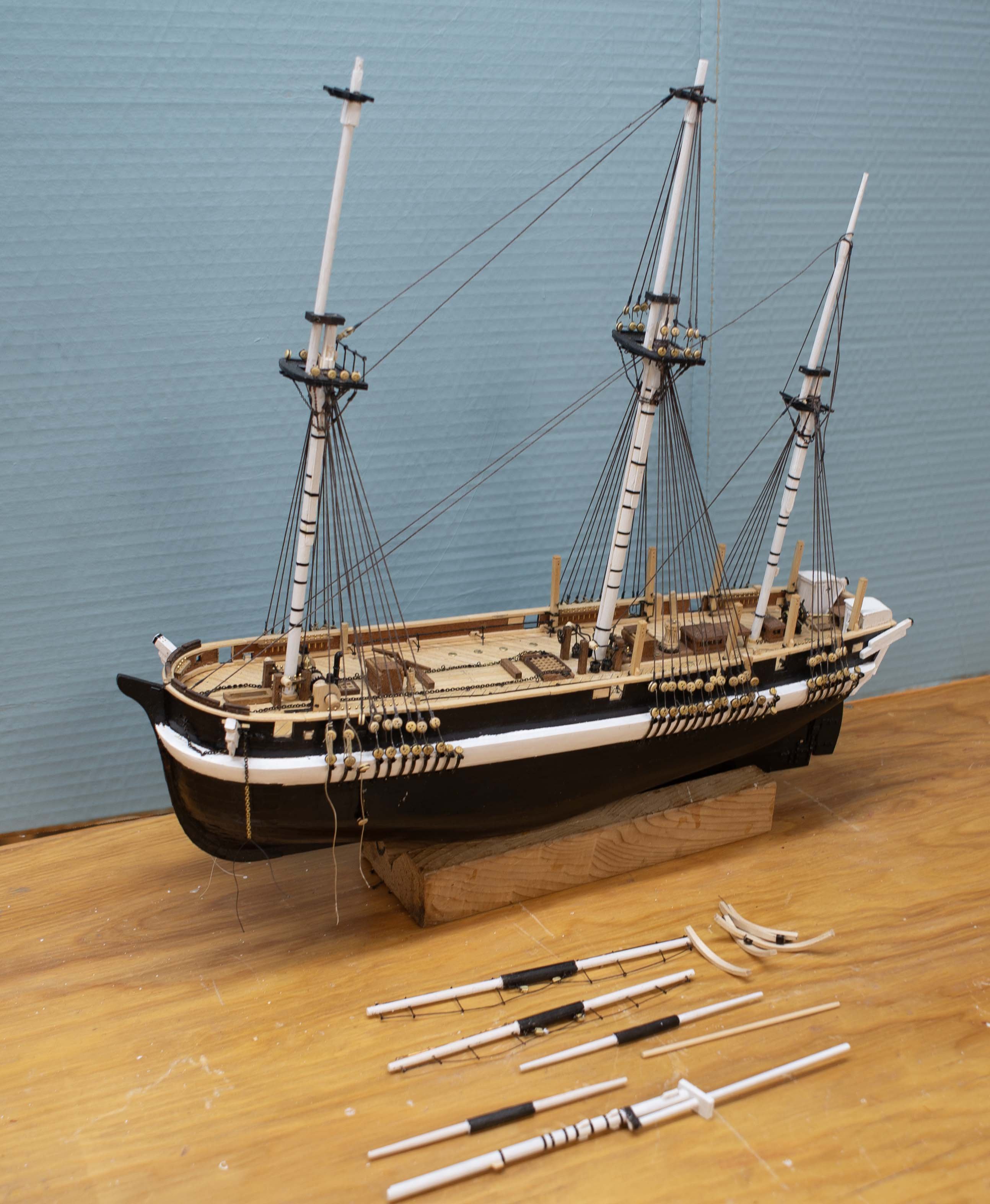
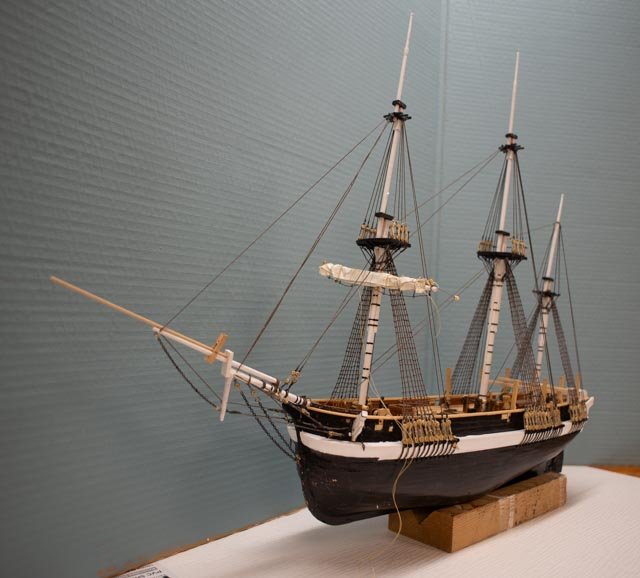
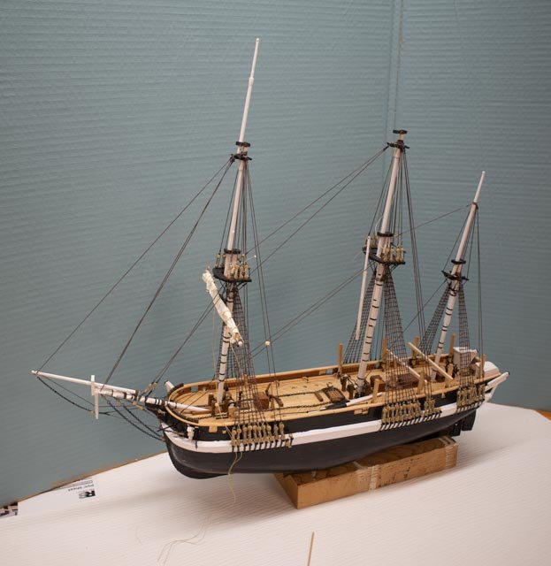
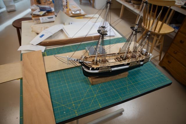
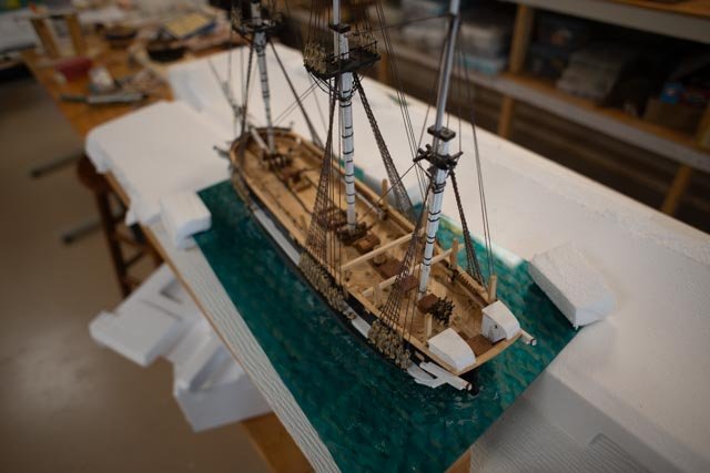
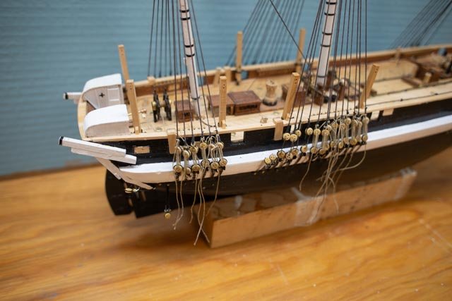
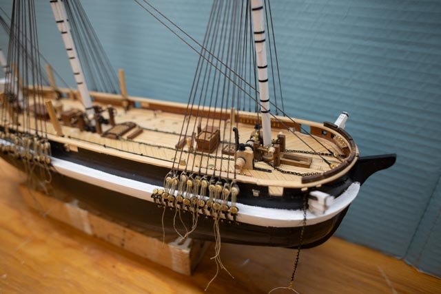
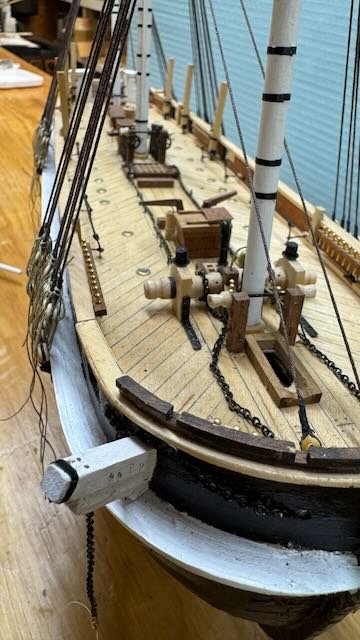
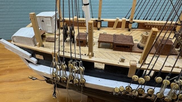
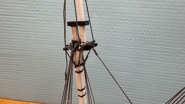
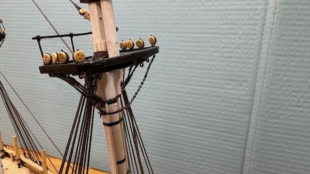
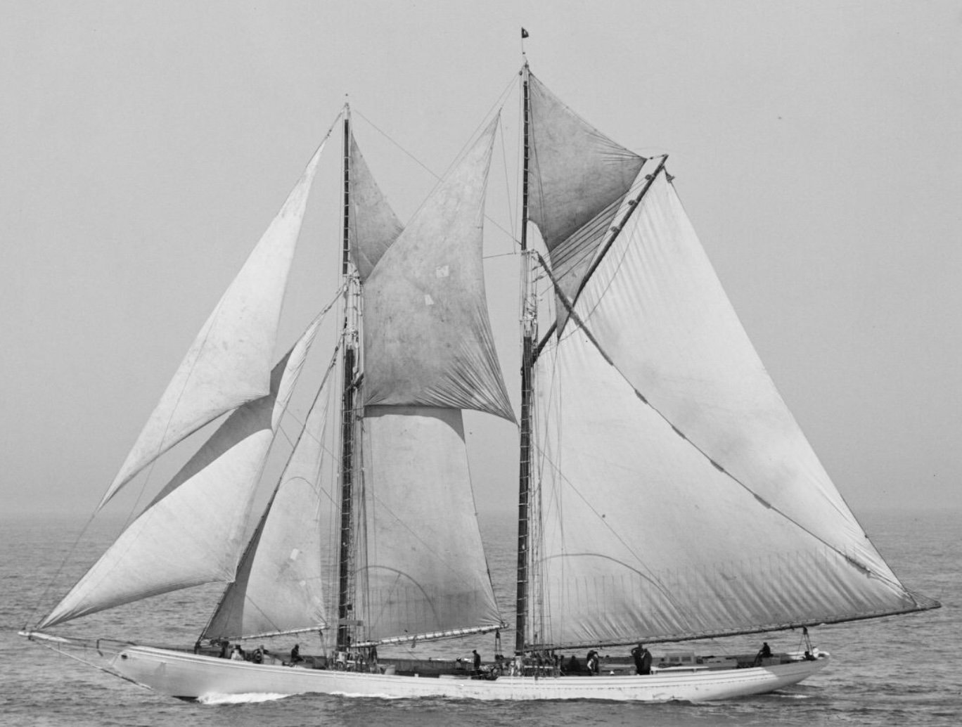
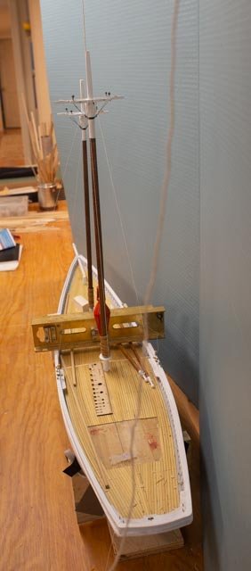
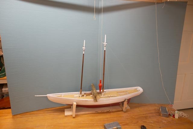
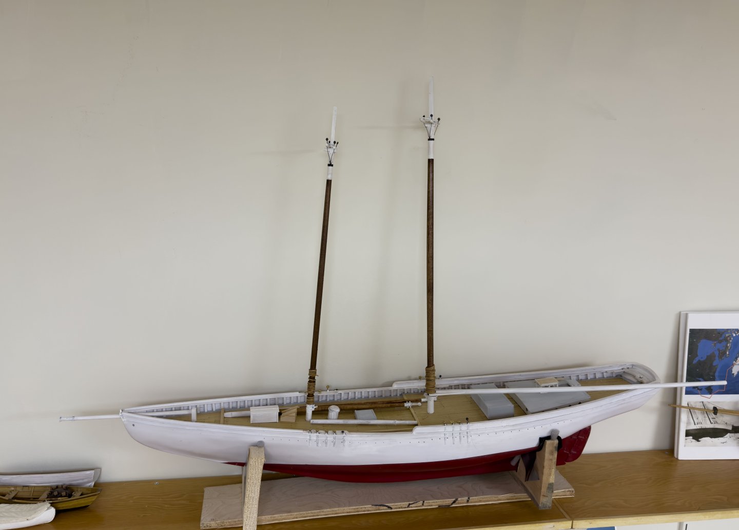
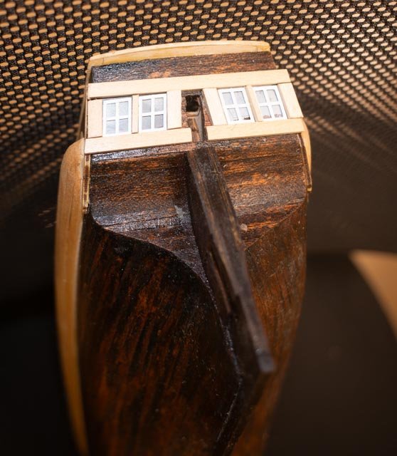
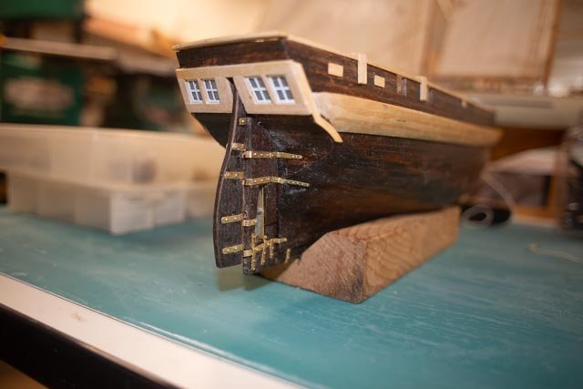
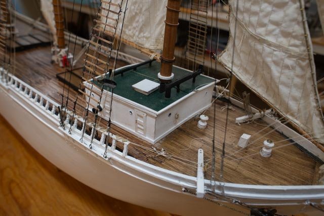
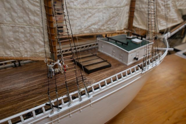
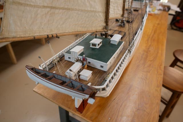
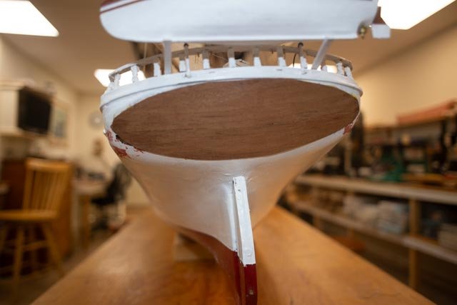
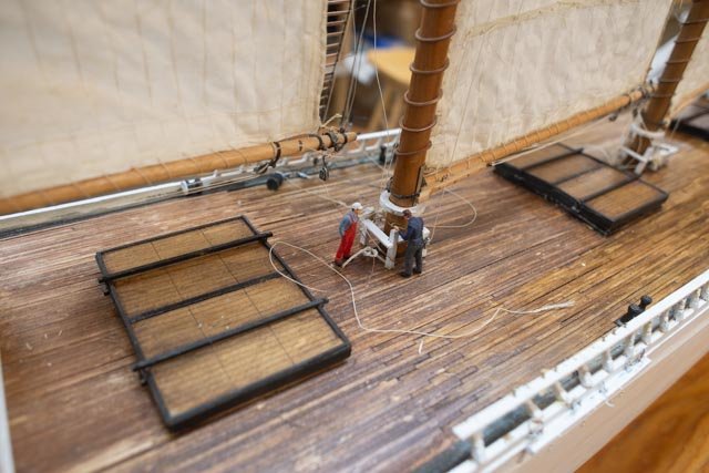
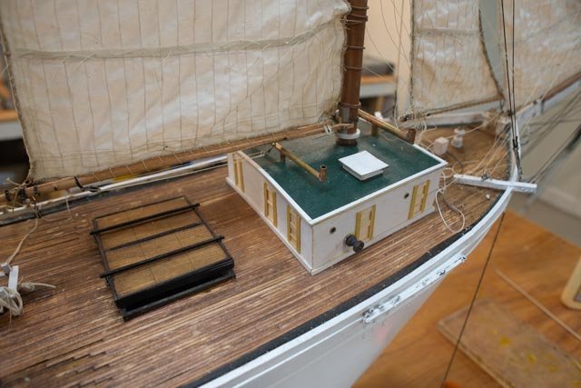
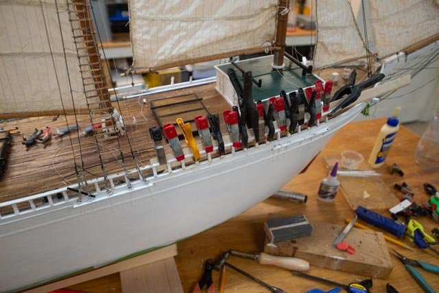
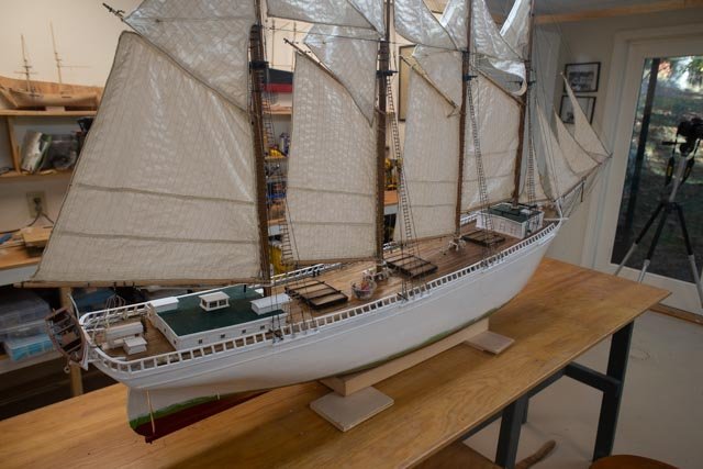
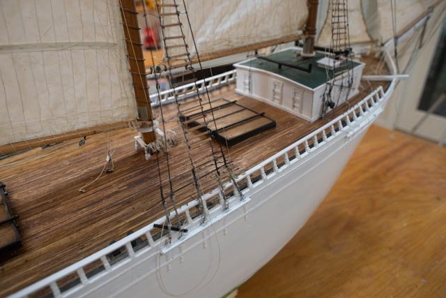
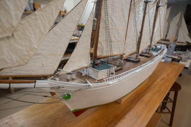
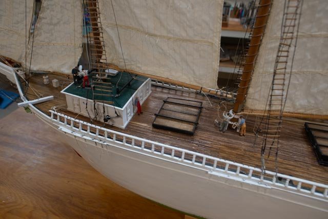
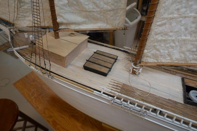
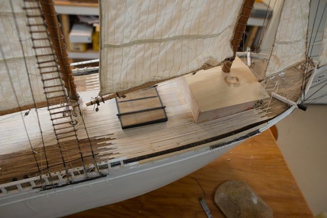
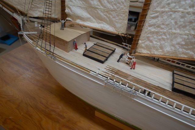
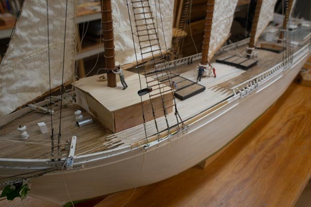
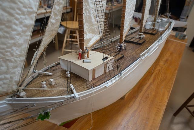
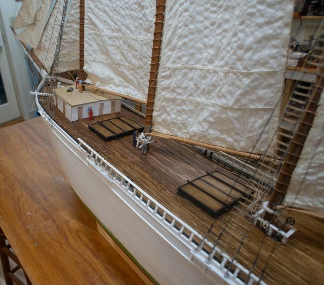
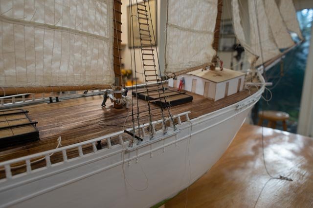
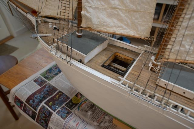
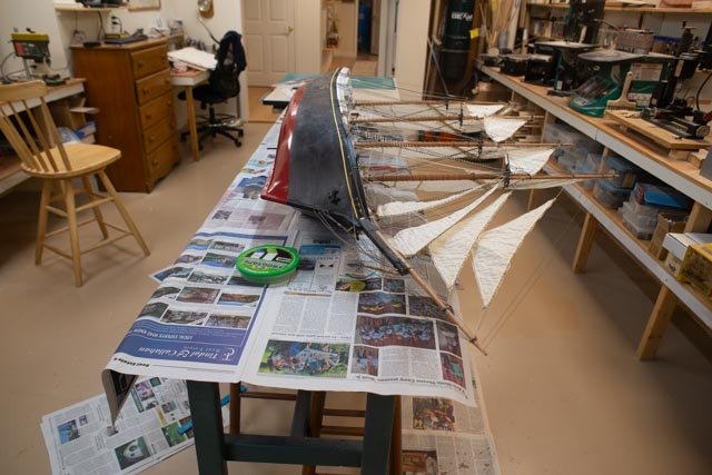
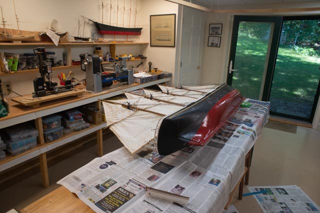
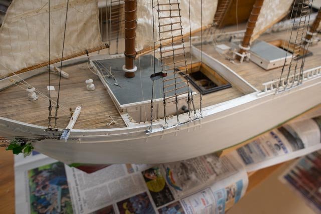
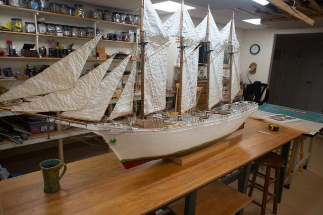
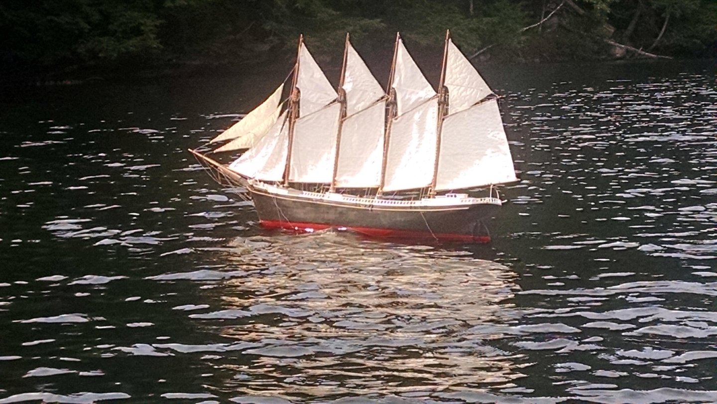
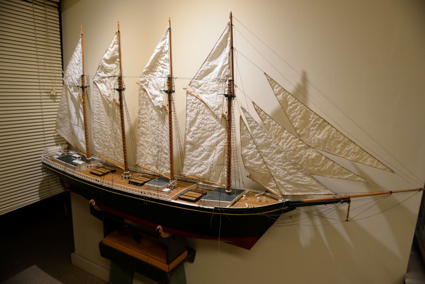
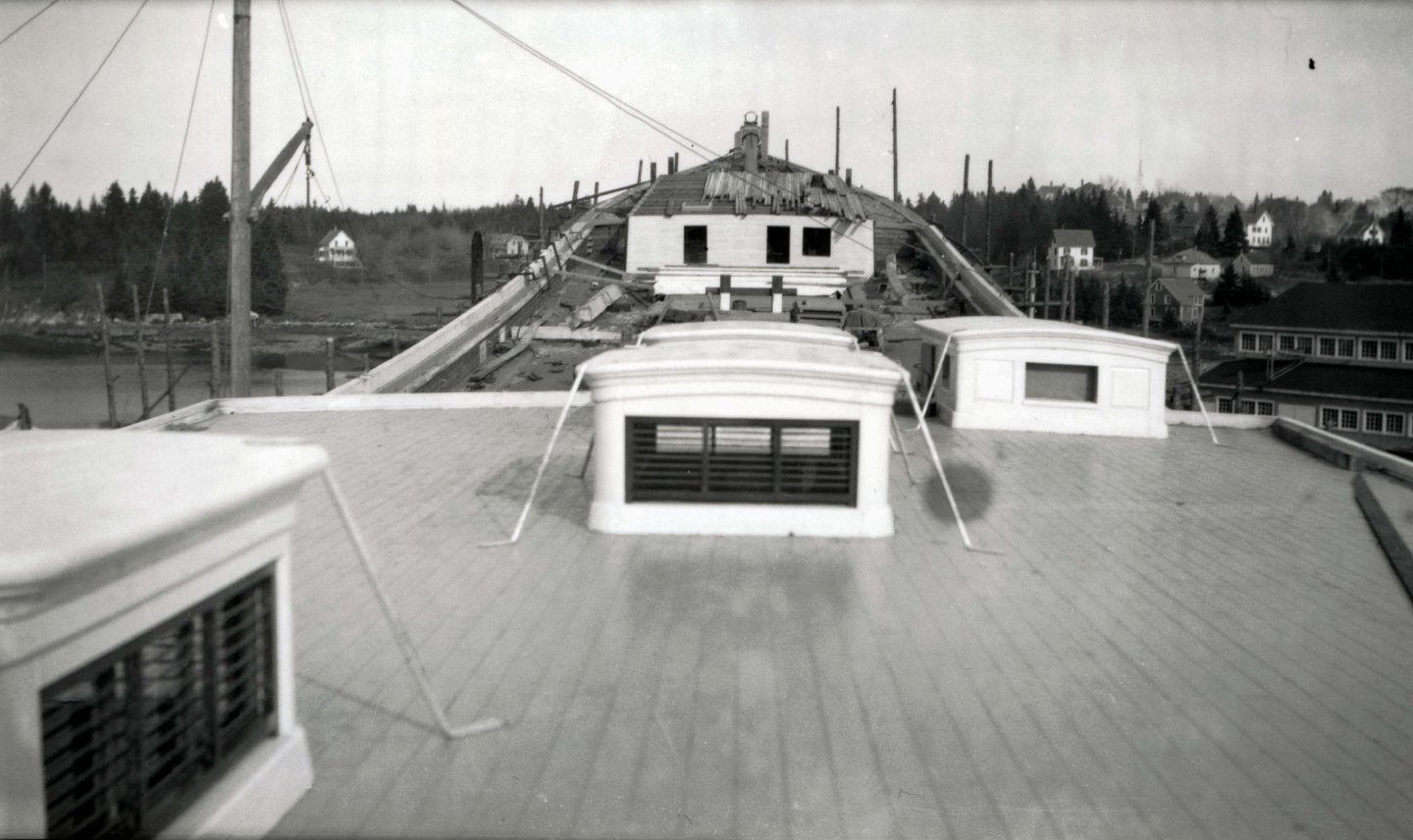
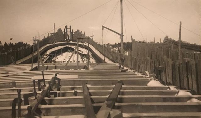
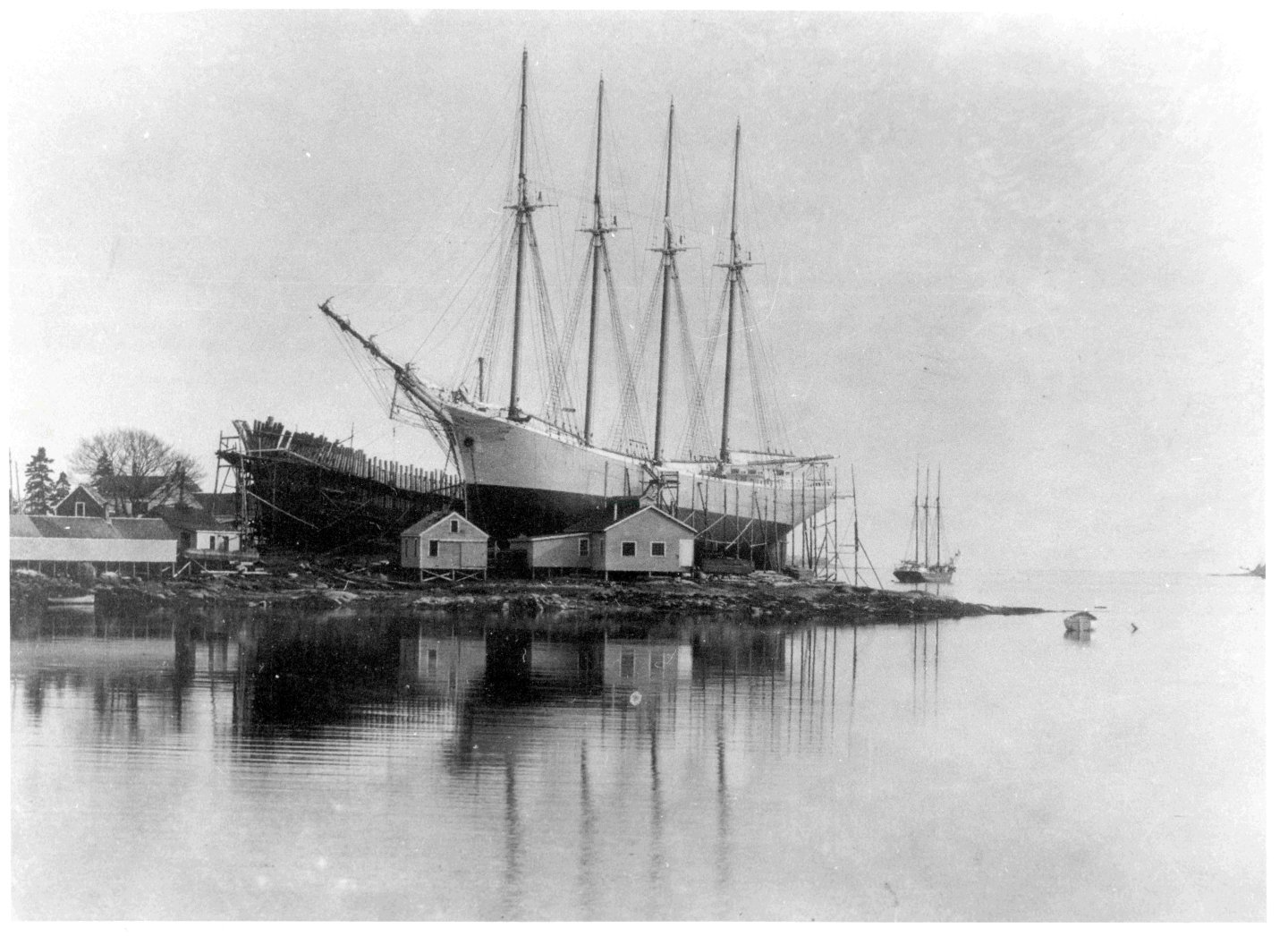
 10 Continued the search for a diorama story I need to figure out what I want to show for a story so that I move forward and plan how to rig the model to that end. I woke up a few days ago thinking I’ve got it. It was fall 1845. Based on the written record that was found in a canister on King William Island, they had wintered in Beechey Island inlet. So, knowing the dangers of moving sea ice, they purposely entered the inlet as the ice around them would be locked by the land. My story will be …they are there and preparing the vessel and shore camps for winter. I also have my own photos …though summer. to try to use for the back of the diorama. here are four photos showing possibilities. 10.-11 they just sailed in and are still fully rigged. They could even have some sails set. Favor the bow on view and maybe have some small boats in the water. the flying jib boom based on the Bett drawings is temporarily inplace 12. The opposite. The flying jib boom and two top gallant masts are down and stored. In this version they are like fully ensconced in ice. 13. here we are…. somewhere in between. The main topmast is being lowered. Question on the state of the standing rigging. I believe they would have secured it above hanging but secured to avoid all the time to fully re rig come spring. I need more study there. In this view I removed the flying jib boom, but I am not sure I want to do that…again more thought and study. The problem to me is where to study this type of question. How to reduce high rigging weight to stabilize a vessel spending the winter ice bound. I have read many books on the explorations, and they contain very little information on that type of subject. Maybe there is more out there to be found. One of the members of our guild a retired boat builder with much experience said it is all about the weight. The masts were dead weight and had to come down. My source for study will be fun of course. Looking and looking some more for paintings of the time. My next month is going to be to figure that out, probably using guess work and seeing what looks good. Also, the hot wire cutter just showed up, so it is time to carve some ice. All for now
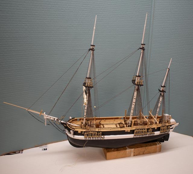

- 62 replies
-
- 4
-

-
- Arctic Exploration
- OcCre
- (and 2 more)
-
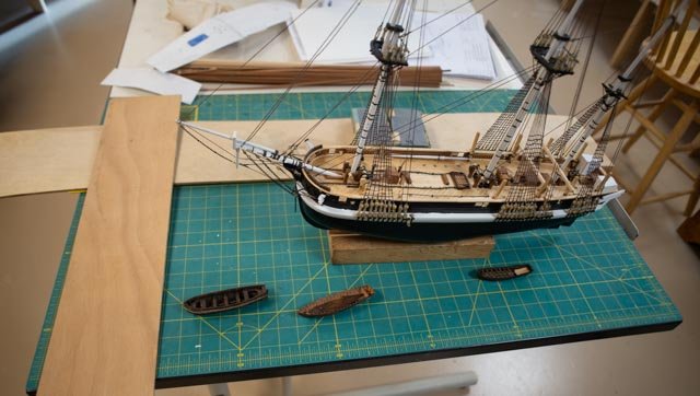
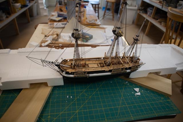
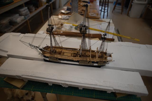
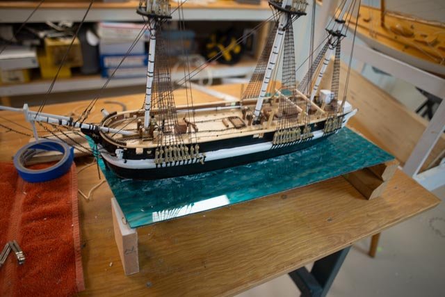
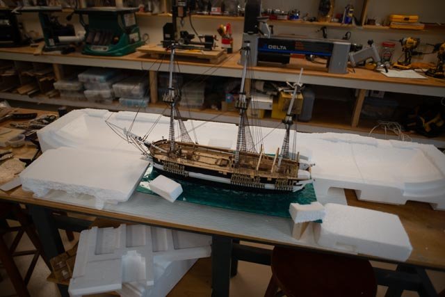
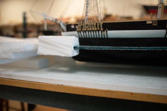
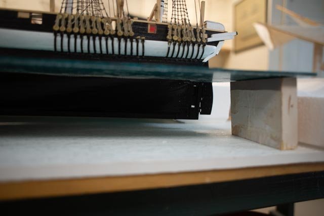
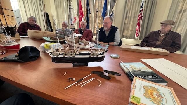
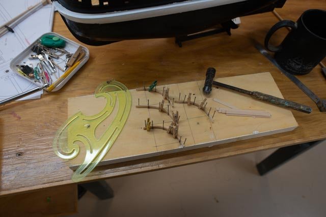
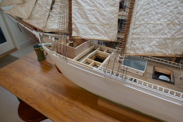
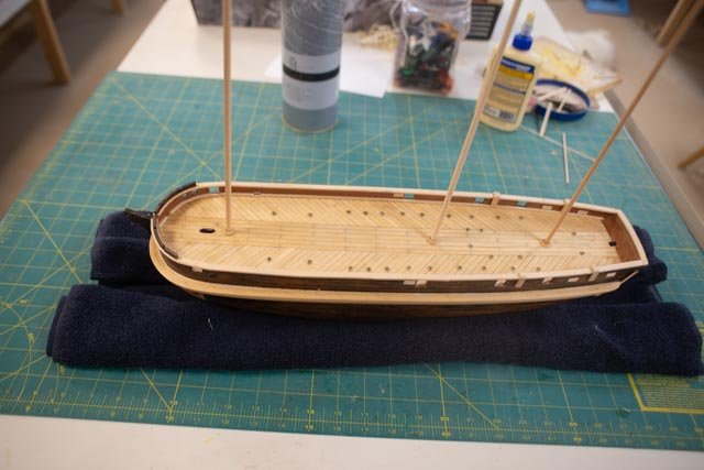
10 concept for the diorama This part of a build for me is the most fun. I want the completed effort to be a prop for telling a story. The first question is what story. I am not fully sure yet and what follows is some of the thought process. I find that laying it out and trying to discuss it helps my process to find the way. Some may say this is backwards, but I want to figure out the size of this endeavor. I already have two 7-foot models and that is out. If I just want to show the model sailing, we go say 2 widths by 1.5 lengths for starter. If fully rigged that means 28 inches by say 5 inch hull or 6 inch yard arm. That could mean 42 inches long 10-12 inches wide. Wow. Still a bit big. I am thinking about winter rig, no topgallant masts and no flying bridge boom. That knocks off 3 inches in length and four inches in height. So, let’s try some stuff 1-2. these photos show the winter rig on a cutting board with planks laid out for a potential size. The second photo adds small boats in the water / or on the ice which will be likely . the size is 32 wide by 16 inches deep for starting point. 3-4 here we start the fun. I have a bunch of Styrofoam from a tv hanging around to play with before it goes to the dump. I cut out the shape of the hull and stuck the vessel into the ice. This is interesting but not the real story of the 10 years of Antarctic and arctic sailing and wintering. We know they survived 1836 Hudson Bay and 1845-46 at Beechy island. They went into and out of the ice. Sea ice in Hudson Bay nearly ruined them. Bay ice at Beechey was fine. We know that to survive they removed the top gallant masts and the flying jib boom and built tents over the deck. These next photos follow a process. When I built my schooner Bowdoin diorama the story was coming out of the ice way up in Greenland in July 1924. I am thinking more of HMS Terror going into the ice in fall 1845. 5 I bought a cheap piece of acrylic that came 12 by 19 inches. It is a task, but I got it cut out, so she can sit at the rough water line. There is no texture in the acrylic, so I am not satisfied. I have seen how to fix that on U tube but what an ordeal. 6 I surround her [ almost] in the forming ice. The harbor at Beechey Island is huge. I was surprised by its size when visiting there last August, and the complete surrounding by land that would protect a winter ship or fleet from the moving sea ice. 7 by playing around with ice above and below the water we still get to see the hull. There will be no bottom at this scale so either ice or blue paint could fill that view. 8 this process solves the issue of not wanting to remove the rudder and prop😀 9 looking from above I think I am moving toward a story. The acrylic has no texture, and it was too small. I need to have more of an open lead that they are in. I will go back online. I am sure I will find costs have skyrocketed since I bought the 24-inch piece of textured acrylic I used for Bowdoin. But we all know there is little fiscal responsibility when it comes to modeling the story. Cheers
- 62 replies
-
- 7
-
-
- Arctic Exploration
- OcCre
- (and 2 more)
-
Thanks Keith we hit -3 F last week. walking house to car to grocery was an adventure. working on a model is a good excuse to stay inside. The more I think about all these people that went north..wow.
- 62 replies
-
- 1
-
-
- Arctic Exploration
- OcCre
- (and 2 more)
-
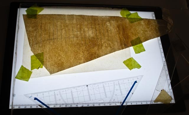
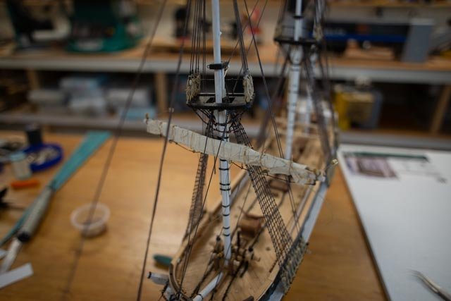
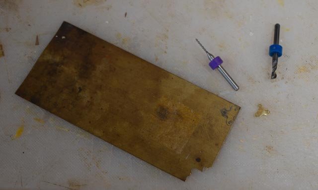
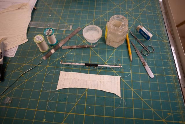
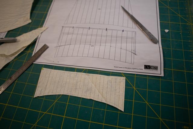
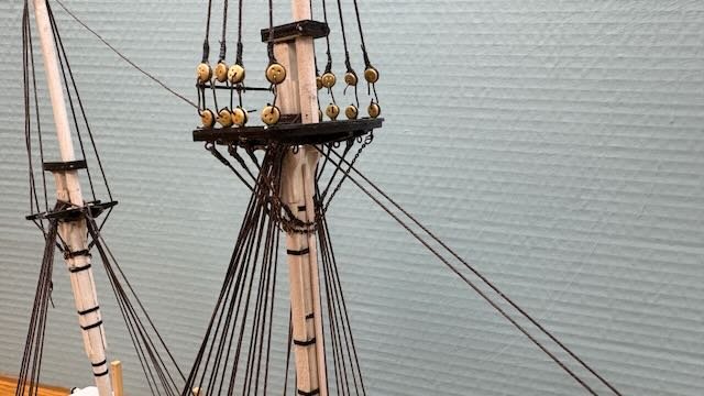
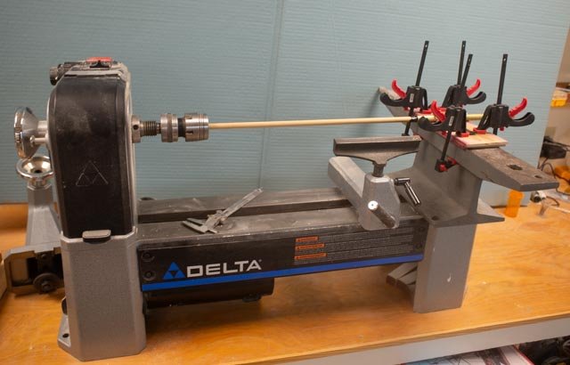
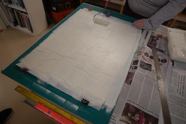
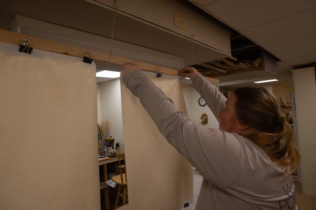
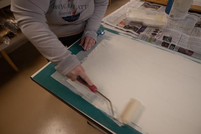
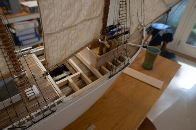
9 Winter continues update 2 Thanks to those dropping in and the likes left behind. This update is a continuance of the previous one called winter work. We finally got a real cold snap, so a little more time was spent in the shop. As work continued on the progression of ratlines, I decided it was time to figure out my first yard. There has been much written about the large seams in the kit sails and the use of cloth in small scale. I learned how to play with silk span a few years back, so I am off in that direction. I used the kit sails/sail plans as templates. 05-07 These photos show the process I chose. I have a slide light pad that works great for tracing small sails. I lay plexi over it so no damage the the sof screen. I first traced the sail from the kit plan. I then scaled the seams for 24 inch so there were roughly three for every two in the kit. One can see I also chose remnant sheets of dark silkspan from previous builds so the sails will look really old and beat up. I recently have a bunch newly prepared for my schooner build and it just looked too new for this story. The second photo shows the silk span cut out, and the third with edges glued up over strings on each side. One lesson I learned the hard way on several previous attempts, is whatever we do, silk span sails seem to grow. That means if following just drawings, they will be too big for the model. Here too I had to cut back both ends so they would fit on the yard. 08 When it comes to supporting the yard I felt I wanted a yard crane of sorts. Since it is quite small and sort of hidden, I chose to make them up out of a brass sheet. Here I share the low-tech approach of drilling then Dremel grinding and filing to get the shape. 09. my first yard with my first attempt to furl that sail as it would have been in winter. I hope by the fourth one I can think more positively about it. getting the rest of the lines hooked up and tir=ed off will make it look much better. 10 just to show the lower masts and bowsprit standing rigging is now all in place including all those wonderful ratlines. Now I wonder how I will be able to get around them for many of the running rigging connections in the future. all for now
- 62 replies
-
- 5
-
-
- Arctic Exploration
- OcCre
- (and 2 more)
-
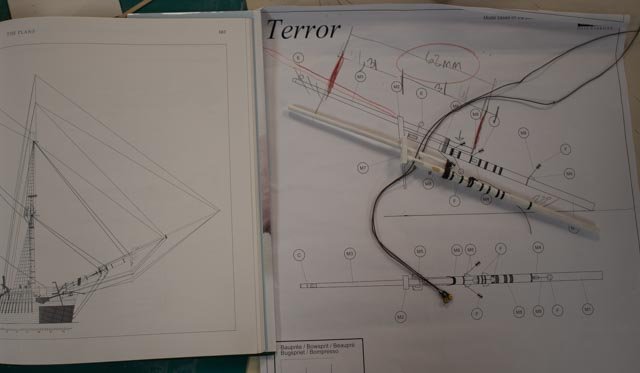
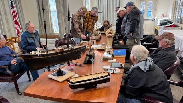
09. winter work update 1 This following update will be one of several that simply follow along through the long phase of working on deck and in the rigging and beginning what may be the overall display. Let’s call it winter work. First up are a few changes I find from the kit that are needed to get closer to our new friend Matthew Betts 01 this image shows the page from the book showing the bow sprit and then the impact with the kit. I also recently saw a painting the verifies there were three separate elements. Now I believe I will have the vessel in ice with the “outer jib boom” and two top gallant masts lowered and stowed. As to the Bow sprit assembly, I must rework what is already built, I need to slide the inner jib boom back to match. It, and the bowsprit are both shortened a bit as well. 02. I got to go to out guild meeting and pose some of my thinking about the diorama with the group. The three little boats are the kit supplied metal hulls. 03 This image is looking the first buildup of a yard. On the right I have used lashed line as per the kit. On the left side I have used light weight annealed steel that I prefer for this type rigging. I find with some of my work that is now ten years old, the thread connections are not great. I think I prefer the steel and will decide in another week or so as I get ready to get the two lower yard ready to install. 04. just humor to share a photo full of the joy of ratlines. I have started on the little boats, and I find some of them are well above my pay grade. I hope to get some done so they can help me think about the display. cheers
.jpeg.2b1c63cafc4ae9d0bdf6e95e13f83069.jpeg)
- 62 replies
-
- 2
-
-
- Arctic Exploration
- OcCre
- (and 2 more)
-
Dear Guy first happy New Year The deck looks great and at some point you will add some form on finish to it and it will sing. We don't have much lime wood on this side of the pond, so I found it fun to work with. the variation helps to delineate it too. the herringbone pattern is unique too I recommend you add to your reading list the wonderful book by Michael Palin on HMS Erebus. cheers Jon
- 73 replies
-
- 2
-
-
- Arctic Exploration
- Erebus
- (and 1 more)
-
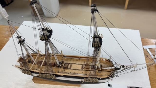
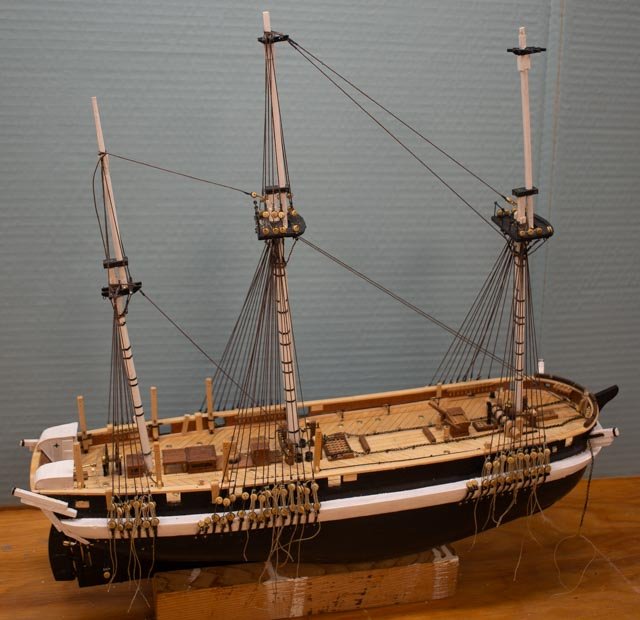
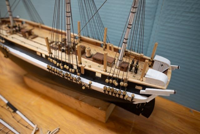
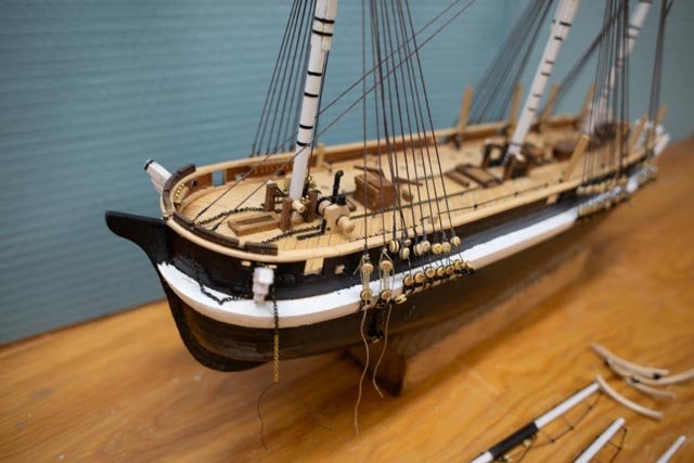
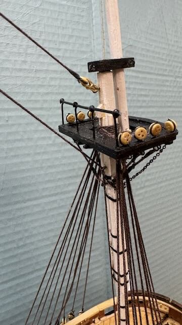
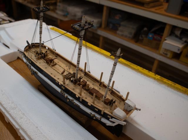
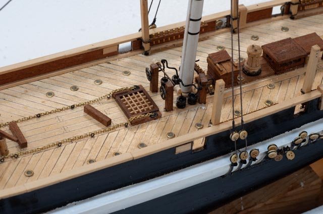
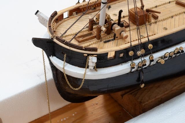
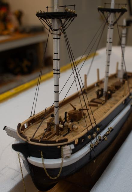
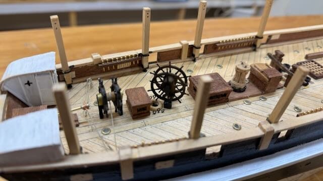
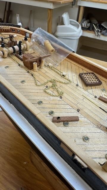
08 The end of 2024 and my lower shrouds are all in! As this year draws to an end, our Xmas visitors have gone home, and I got the shop back just today. A little progress was made, but more important was to take some photos to document progress as of the end of the year. 01-02. First up we have two overall shots of the overall scene. One can see a little progress on starting to make up the multiple added spars. I celebrated getting the 13th and final shrouds on the lower main mast just before cleaning up time. Most shrouds still have their little wire hooks. 03-06. here are 4 shots from the four quarters. One might note that the lashing of the dead eyes on the starboard side is progressing. I not different approaches to handling the extra line. In USA schooners the tail drops down and ties off to the last riser. I see some other modelers have taken them up. I have not decided but think I will do what I believe is common at least here in US to drop the lines down and use thin thread to tie them off. 07-09. here we have three photos of the on-deck status. I made up the little brass racks to hold spar spars and things and am now getting to a check list of all those little eye bolts and hidden hocked blocks I need for yard halyard and the like. I am not sure how many I can fit with my awkward thumbs. I much prefer 1:48 where I can see better and handle parts better. I also not that after adding my homemade elm pumps, there really is not a lot of space left to stack boats. That will be a while from now but even so, it seems tight. The kit says raise the boats up high, other builders have the boats low even on a sled, a more practical solution. We’ll see. 10-13 here we are in the rigging, the part I like the best as it is a constant learning curve. I know schooners well. Barks and ships are a big learning challenge for me. Fortunately, I have the Betts book, and I am using that as best I can. I notice subtle differences from earlier builds. One example I learned was the use of chain. Now my chain is 42 links to the inch, which is tiny to say the least. but at 1:75 the links are almost 2 inches. the next size up they would be over 3 inches which I guessed was too big. I foolishly painted the chain after installing because painting first makes it unmanageable, and I have never successfully blackened chain. It’s a bit of a mess and hopefully some more dental work will help. So the year closes with this a big challenge that I look forward to pursuing. My big Schooner is still waiting as I have about four more repairs to make to a local restaurant collection. Mostly busted booms and bow sprits then re rigging. Happy new year

- 62 replies
-
- 5
-
-
- Arctic Exploration
- OcCre
- (and 2 more)
-
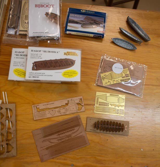
07 time to blend early rigging with other on deck work Thank Keith for following along and others for their likes. It is encouraging. I find that each build teaches us lessons on how to better set sequence. I am not sure however that I can remember previous lessons. Regardless I am moving ahead with masting and standing rigging trying to be sensitive about blocking things out. A good example is to decide what gets done off the boat and brought in all complete. I suspect the top mast work might be better done off boat, but have decided to move forward with lower masts. On a similar note, as tight as things are, I suspect tying down boats stored amid ship may be difficult if left too late. Also, I am beginning to fool around with how to present the model. A funny example to consider is, if the vessel was “pinched “, locked in ice, the rudder and propeller that we all carefully installed should be removed. One might say I should show her just before getting pinched. A little water to be present. We’ll see. Progress The first 2 views show two masts starting to be rigged. I will not lash the dead eyes now but leave them with bent wire connections in case I need to take them out. The mizzen top is being rebuilt as I learned from other builds there was no “top” on that mast. as came in the kit. One can also see I have Styrofoam on the table to get my thinking going on what I want to show. I think the story will be they are pinched and stuck. The second three shots show a little more detail. Up forward I found I need to buy some hearts for the shrouds bob stays etc. There is still a lot of stuff to go inside here, and I am focusing on getting that in before lashing the shrouds. Amidship, I received some pump wheels. I am holding up the center until I figure out which two boats to store there and do I make a sled etc. Further on the mid-section and aft I need to make the racks for spars and do all the other deck stuff before blocking with shrouds. Finally, I have begun the build within the build that is key to Terror project. They reportedly sailed with 12 small boats. There are several lists, and, in the photos, I have accumulated a variety to build. I have currently a total of 12 including the 3 metal hulls that came in the kit. I have always struggled working small and have challenged myself to start with these kits and then see what I learn. In the views I show the group of small boats and then the Amati chain plates that I bought to simplify and I believe improve on the kit. onward we march...
.jpeg.4f370a834549874dd96507e61651d7c2.jpeg)
- 62 replies
-
- 5
-
-
- Arctic Exploration
- OcCre
- (and 2 more)
-
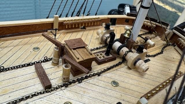
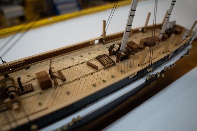
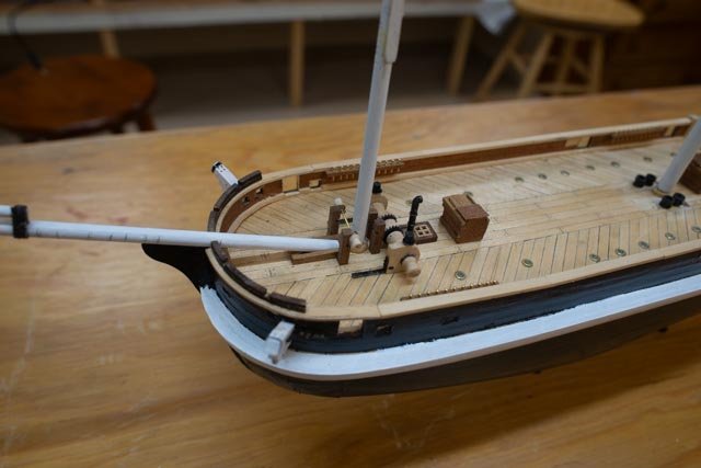
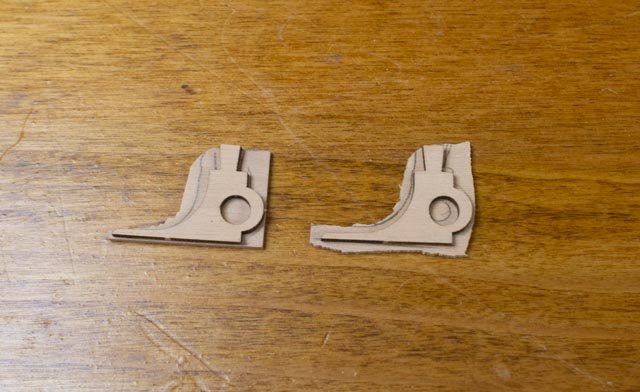
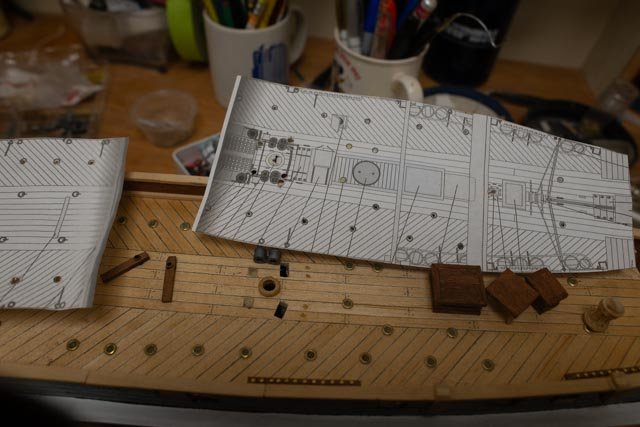
06 time for a check up on deck progress. thank you one and all for your likes. I, like many others, get to this stage of a build and go… oh my! there really is a lot to do! I have been working away and making some progress. Thanks again to those that went ahead of me, as I am spending time looking at their posts and Bett’s book for help. Those before me said; Beware the kit has some issues. Well, I am trying to fix some things. It is fun to do. I will not try to list every change as I go, but I am off and running. The following images capture a few attempts to follow the plans from Bett’s book. A few examples are nice, and few ended in my “oops: I scaled his plan and used it for layout. First up were all those port lights…no problem found. One who fully studies his plans first, might see that the literal scale of parts as shown on his plan are noticeably smaller than the model kit drawings or parts. This issue comes up a few different times. I marched ahead just using his plan and got bit. On my first attempt I used the layout to cut holes for the bitts. A week or so later I got the little Massey pump kit parts outs and there is no way to fit them between the bitts as shown on the drawing. I had to plug two holes and recut the forward bitts, so the pumps would fit between. I also picked up that there are a pair of bitts on the aft side of the main mast to carry both the load of the fife rail and the pump handle. I chose to keep using the kit sized bitts and that is what I got. This 1:75 and MM vs inches throws me off. Perhaps all the bitts should be smaller. Who knows. The last picture shows what I have going forward. 1-2 shows the plan and holes and the big pumps. I moved the holes, added the double/pair of aft bits and just ordered some flywheels. Forward bitts and things I suggest the same. I was only able to fit 4 pins in the forward curved rails. It seems that all this timber is oversized. So be it. Same thing for the stern davits. I did bring them down to be closer to the plan. I think 5x5 means ( 5x75=375/25 = 13 inches. Much too big in my mind for davit. 3-4 Second were things that I tried but decided not to use. First up was the windless, where I used the plywood parts as a template for a boxwood piece. But then looking at the cast metal I decided to make my own. 5 I was able to go to a meeting of our local Model club, Downeast Shipmodelers Guild associated with Maine Maritime Museum. A skilled member shared with me that painting the hull black was a much better presentation than the walnut-stained wood he saw earlier at our recent club showing. I thanked him! 6- 8. I learned from previous blogs that the main davits were critical and different from the kit. I tried to use their smarts and have progressed as they need to go in early. I also made my attempt to make the water closet/ bowsain’s locker. I still am a little dubious on this subject. Some 50 men on board and only one head other than the captain’s personal seat of ease. Normally officers share something the aft galleries, but these were removed for arctic service. Therefore, as I find Betts drawing nonspecific as to port and starboard but only one drawing conflicts with his addition of the forward door on the port side on his model. Thus, I made them as if both were heads but added the questionable door on the port side. The things we can get hung up on ! 9-11 . I got an order of lettering for three different builds. I think the Terror came out OK. I had two more-dimension issues. Based on many comments of earlier builds, I went online and ordered a 3 D printed 10 spoke wheel. It was for a close scale, but it is easy to see way too big. I retired it and went with the kit wheel. However, I note that even it is too big to satisfy Bett’s drawing. We do the best we can and move on. A third issue is the reported elm pumps just aft of the forward gangway. I ordered the best I could find but it is double the size. I used it for a model and made my own. I set the Amati 20MM pump behind to show how big it is. Well, there is so much to do we shall just keep on as winter and the holidays are headed our way Cheers
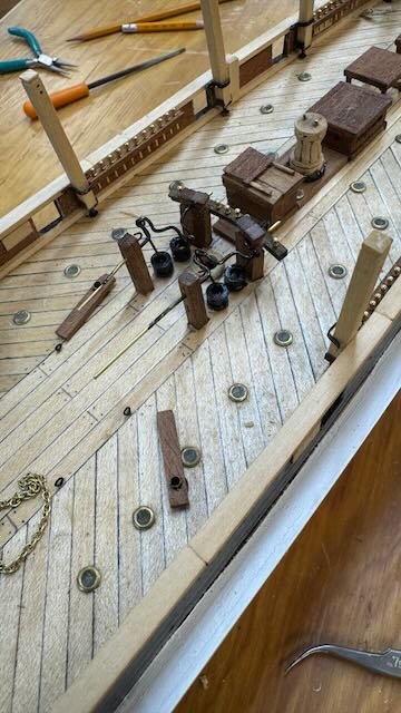
.jpeg.e9f349cb2ba84853dfb811f3c511175d.jpeg)
.jpeg.d974813f5b282243ad25613a9d6c22c8.jpeg)
- 62 replies
-
- 5
-
-
- Arctic Exploration
- OcCre
- (and 2 more)
-
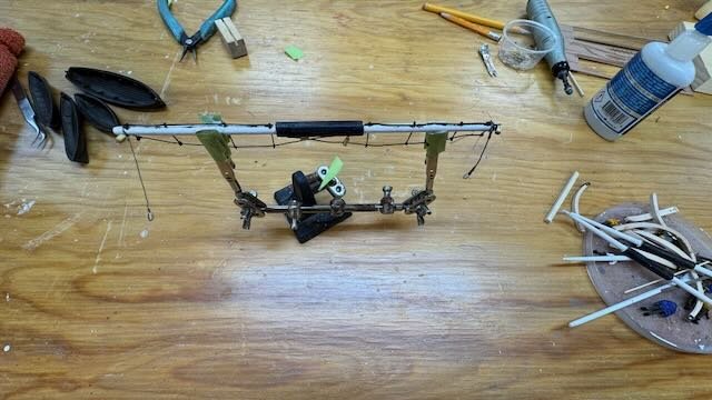
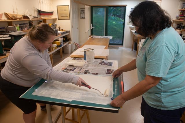
11 This update covers some down time as I travelled North through the Northwest passage in August and a few extra activities in the model shop this fall. Before setting EH aside for a bit of a rest last August , I had fun on the shop toys making some of the deck furnishings and spars. 01-04. these photos capture making the masts and setting them up for the right rake 05-9 capture the annual visit of my daughter and some of her friends. She loves to make sails. So since I am out of prepared silk span she prepared four large sheets for me, sure enough to make the sails this winter. I also have found a better image to use for the sail planning. 10 Finally we see EH sitting on the shelf as the rebuild of the schooner Zebedee Cliff took over the shop
-
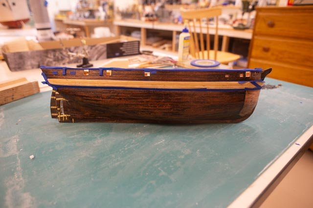
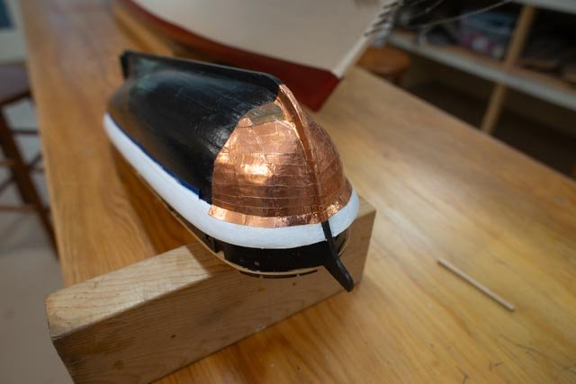
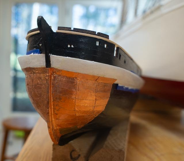
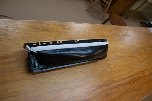
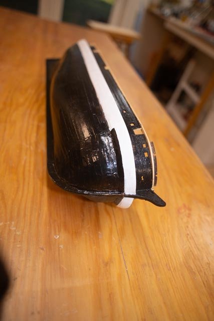
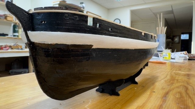
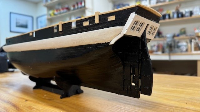
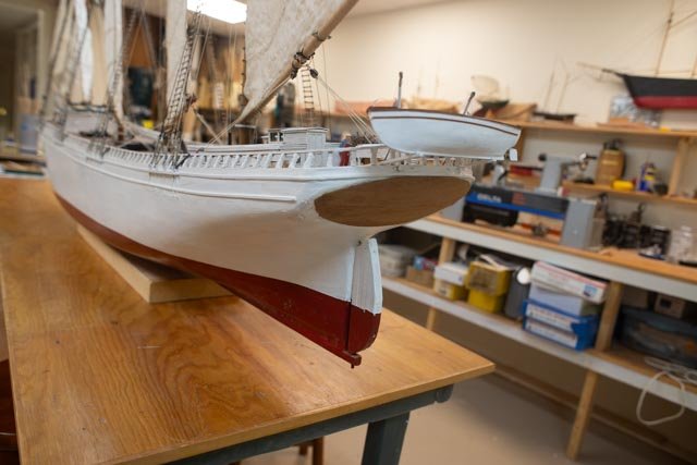
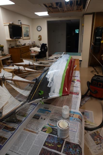
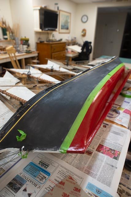
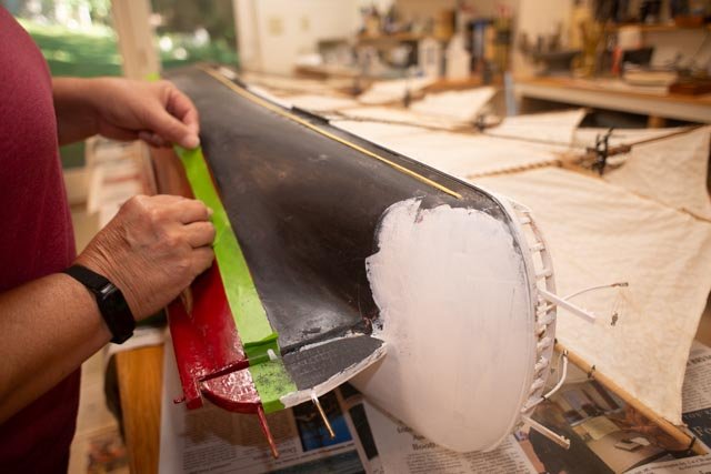
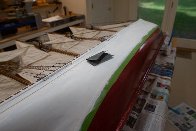
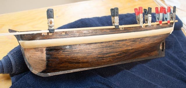
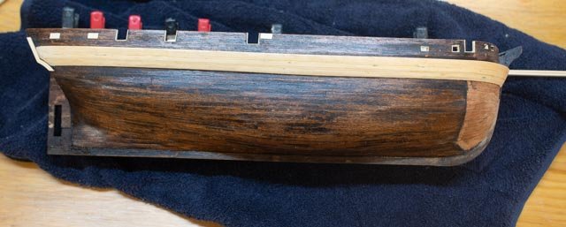
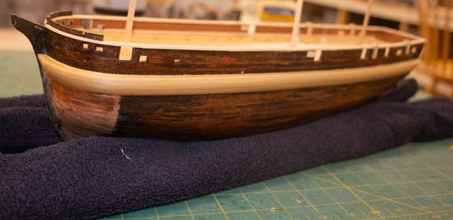
05 back to work on finishing he hull I am finally back in the shop and focused on this build as my big 1921 schooner was just put away and the third 1916 schooner is still resting. I start by sharing the decision I made to paint the hull. The main reason is because I want to try to use the model as a prop while telling the story of this amazing vessel, as its part in the saga of the Northwest Passage. That story must include ice. My TV aged out and I came home with a new one last week and saved the Styrofoam. I will collect other grades and then think more about what a reasonable approach to making ice might include. I have atleast seen some real old age ice pack and it is a strange combination to say the least. For one thing a natural finished model half buried in ice would not make sense. Therefore, despite painting not being a high skill off I go. As I restart this build, I am working first on the general hull completion and also on the deck furniture and masts. This way I can move around the shop and do a little of each and move on. First up, and before I decided to paint, I built out the stern. Oops! I wish I hand decided to paint before. Oh well 1-3. here are three shots showing the stern work as it progressed before paint For the metal bow plaiting I decided to use the copper tape I have. There are so many comments on many blogs about whether to show rivets or not. I believe dots on decking or dots on exterior planking are great. I even have run a pounce wheel when the copper stays exposed. Perhaps a cop out, but under paint I chose to move on not using the pounce wheel. 4-10 here are 7 shots showing the copper tape on. I use compound cement under the tape so it will stay. I have never had just tape remain uncurled in place. I then simply brought the paint over the top. In the final shot we see that work has begun on masting as well. I took this shot because in the winter the morning sun comes through the leafless trees directly into the shop for maybe a half hour and it is fun to be there and see the different lighting. next up progress on deck All for now
- 62 replies
-
- 6
-
-
- Arctic Exploration
- OcCre
- (and 2 more)
-
Thank you Robin I am just getting back to working on the model. I am thinking more about how best to tell the story. I am watching U-tube shows of sailors going through the passage and one things seems sure. The storms are crazy. Also they seem to last for days, unlike here where maybe two days its it. cheers
- 62 replies
-
- 1
-
-
- Arctic Exploration
- OcCre
- (and 2 more)
-
I love the ice. I am at a similar stage and thinking of how best to tell the story. cheers
-
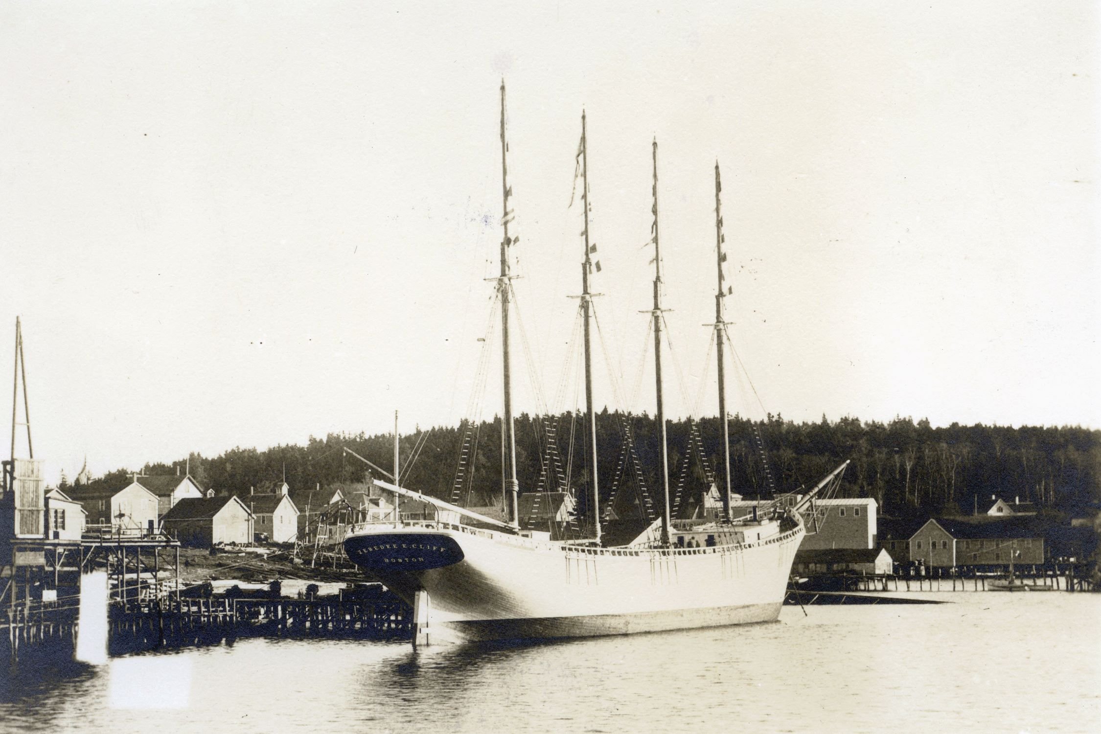
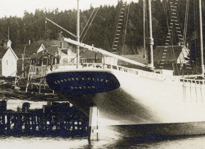
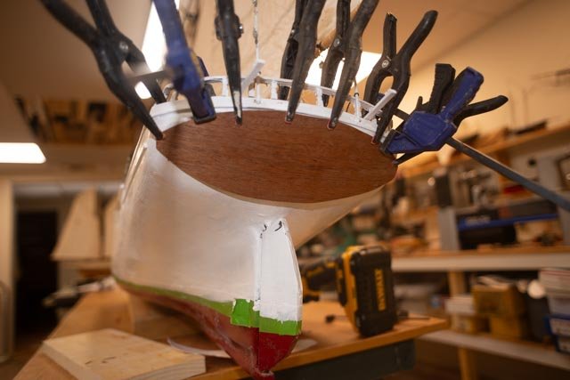
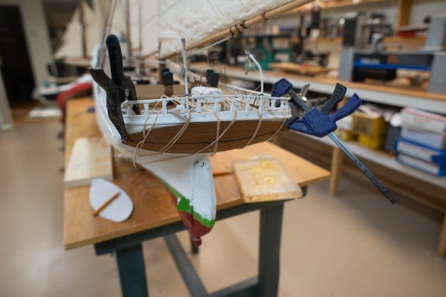
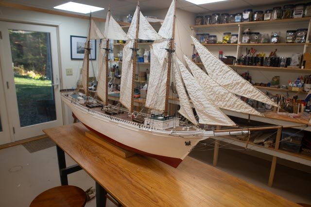
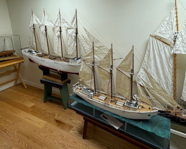
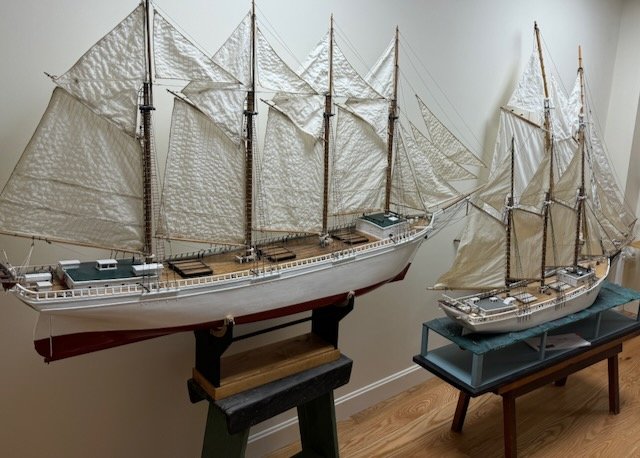
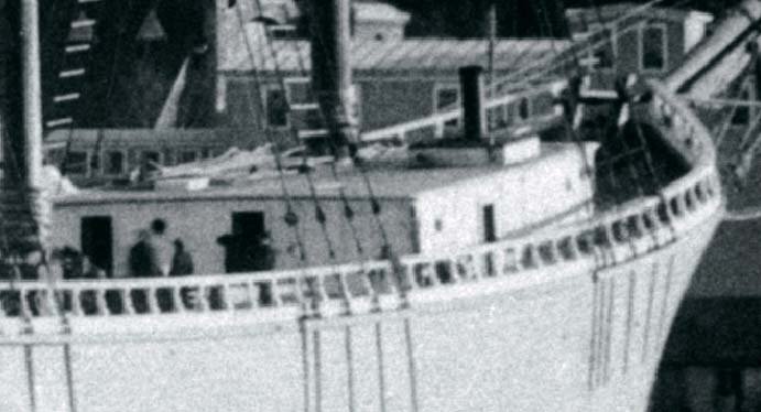
Step 3 get the rigging back together and finish Much of this stage involved repairs, then resetting rigging where it went before and finally adjusting for the raised balustrade taking the forward running rigging. Another final step involved the transom. In the following cropped image, we can see that when launched, our schooner had what I assume to be a mahogany transom. 01. Several years ago, I bought some mahogany veneer. I was happy to find my second use in many years. At first, I cut out the shape, but alas there was no way to get it to flatten over the shape of the transom. Obviously if I sliced it into say 1/8-inch strips it would have gone on nicely. I don’t find mahogany veneer likes that type treatment. In the four views we see the fist “no fit” followed by a mid-section cut away and multiple bands to hold it. Then two views of the final, unfinished. I have ordered letting in vinyl. And will apply it. 02-05 Here I have several views of the focused area of alteration. I also added a little more detail to the aft cabin. Please remember this is a RC boat to begin with, and there are too many areas that could use more and more detailing. The photos did not show the little bars on the cabin features meant to avoid fowling lines. Perhaps these sailors were confident. 06-09. So yesterday I moved her back to here resting place. {Please see her now in the gallery with her older sister ADA Cliff, the three masted schooner built in the yard in 1917. Starting with the completion of ADA in 1917, Zebedee E Cliff, mayor of Somerville Mass took over the yard and they built 4 each four masted schooners based on the ADA Cliff design concluding in 1921 with our altered vessel named after the good mayor himself. 10-11 I am sorry about the scale difficulty but here we are with two rather large bookends. I will share a photo of the naming when it hopefully occurs in a week or so. Cheers
-
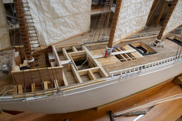
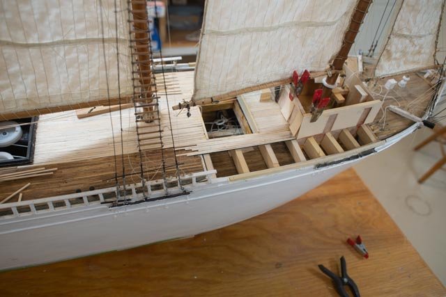
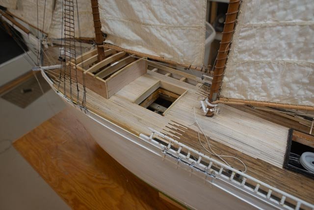
Step 2. Get the deck house, balustrade and other deck work done This second step was basic. There is continuous humor however, as my forced dimension compromise is needed to achieve the goal of switching schooners. Declaring the scale different to make the length of the vessel close [ changing from 1:48 to 1:40 does not increase cabin height and all the other work. I hope the audience will forgive me. Here are a series of progress images showing the fore cabin coming together. The sides went on, then the roof deck, then the stove pipes, the boiler hatch, doors, portlights etc. The main mast fife rail hand to be replaced as well and then the balustrades brought forward. So here we are with the deck work basically complete. Other than a few things like the stove pipe supports, angle braces put on the aft cabin, figuring how to rig the jumbo sail with the high roofed forecabin, we need to get the rigging back in place. Ultimately the naming will be a little challenge, possible experiment and I frea another needed compromise. That will include another story. All for now
-
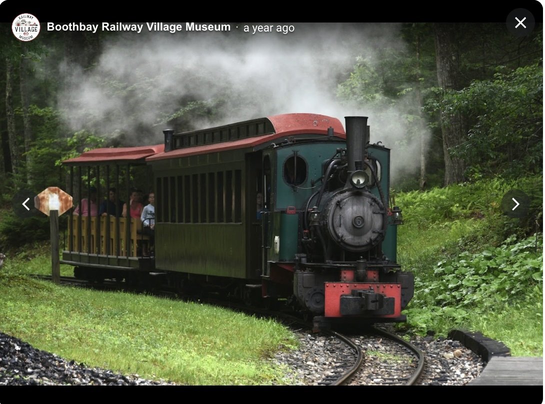
Keith It's great to see your build up and running. Just yesterday I was looking back at your old build of HMS Terror, trying to nail down where to put bitts. I am happy to see this lesson spread out at just the right time. thank you our railway in town is not as exciting as yours. it is part of the 24 inch series that was popular here in Maine, especially in the lumber industry. There never was a train down here at the end our peninsula, but some years ago an enthusiast bought and relocated one here. It is a loop and fun with North pole express etc. cheers jon
-
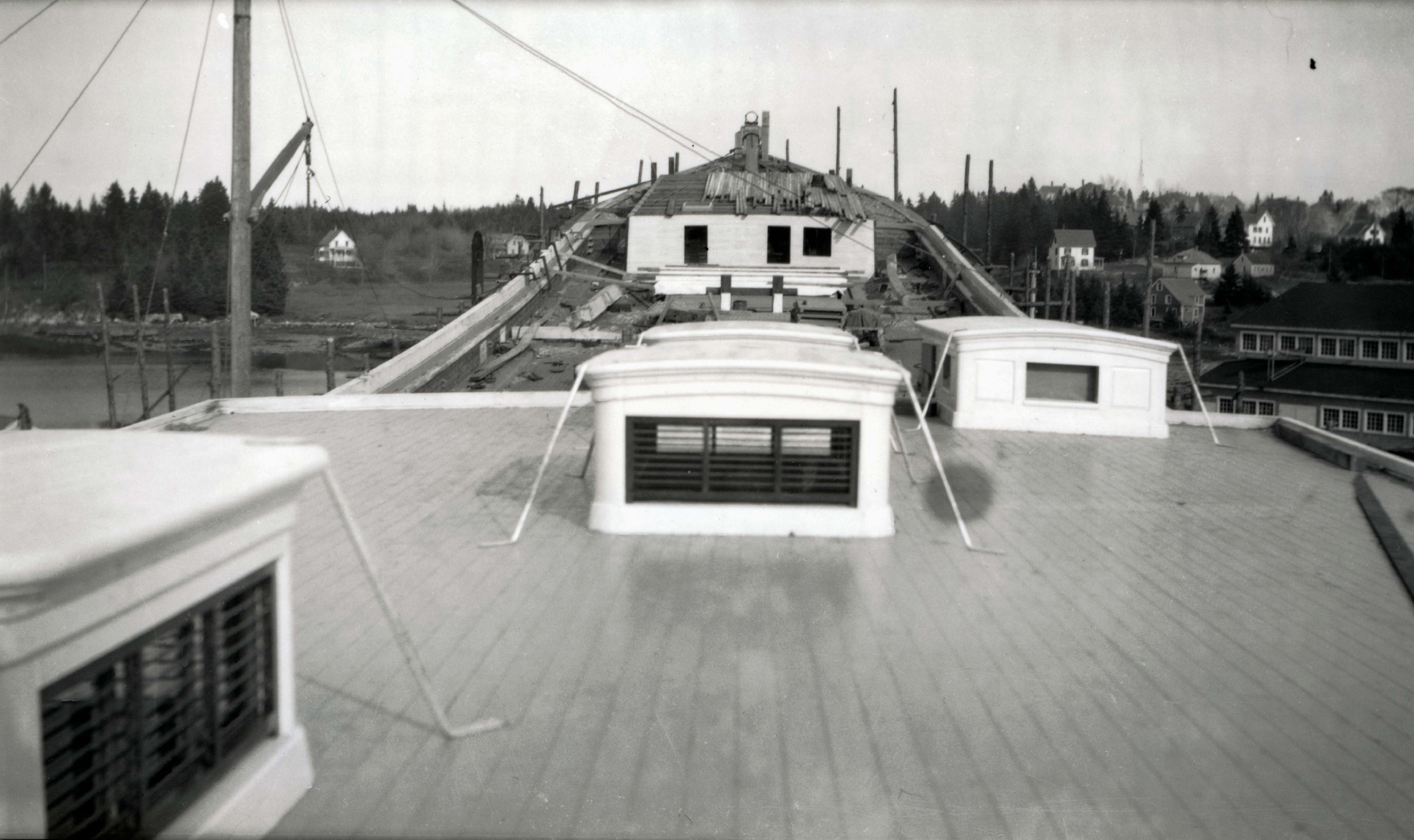
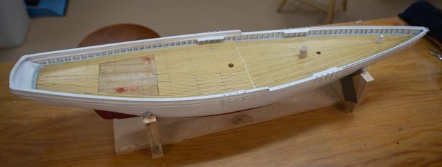
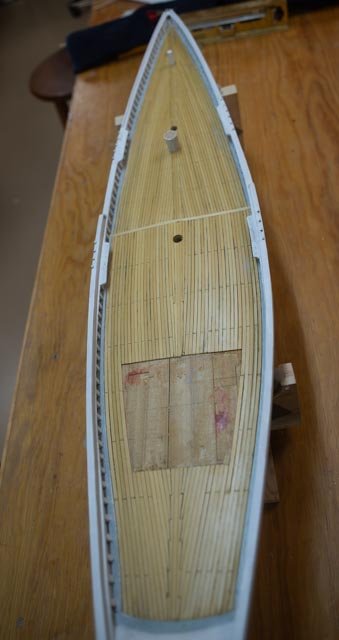
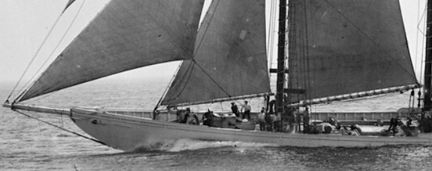
3 decking Decking is an interesting project. It really includes other things that we hopefully think about before we lay the deck and go darn, I wish I had painted that waterway before I glued the decking plank next to it. Notwithstanding a few of those oops’s here we are. I share a few photos of the progress and few showing the crew on board after finishing the deck and thinking about the fore cabin and raising the foresail. I used a little hand rubbed poly over a combination of three stains to try to match the old decking , and it seemed to come out reasonably close. By light washing some of the stain and poly over the old decking it all looks close enough for folk music. The white paint on the old girl however looks tough, but I remind all this vessel was pond sailed over two summers and has sat idle for years. It will take several more attempts to get things close enough, but I doubt she’ll ever be ship shape. Also, painting around completed rigging is a tough order. The point here is that if one had all the time in the world, one would remove much more rigging that I have done, then sanded and painted everything before re rigged it all. I admit here that is not the current plan. The rebuild of this pond sailor is just to have it represent a Boothbay Schooner to accompany the research I did years ago to tell the story of the 12 four-masted schooners built here. Finally, as an old, retired engineer I just have a problem with Charles Notman’s extended poop design. I am now very happy that is no longer the case on the only four masted schooner I have. Progress 1 here is a cropped image of the real Zebedee Cliff fore cabin. This image is what I will try to emulate. 2-4. progress planking. 5-6 last planks are in, and the hatch combing and waterways are in and painted 7-8 the crew arrived and the deck house under roofing is ready. 9-11. the decking is stained and two light coats of hand rub poly. The stain is this sequence….. first cheery, second special walnut[ medium], third golden sunset. Then I did a light wash of the walnut stain over the old decking and two more light coats of poly. So, Step 1 is done now for step two. Cheers
-
thank you John She isn't up to your museum work but she is definitely a lot of fun to do and I look forward to more local celebration of years gone by in our past shipyards. cheers
-
Keith I thank you for your continued interest and willingness to encourage all who share enough interest in this incredible history to build this model. I also enjoyed reading all of your posts and hope someday to see more on your build of HMS Erebus. Now that we have learned that Parks Canada is diving on the [ now Canadian] Erebus first as it is some danger for underwater losses, I can't wait to see their update. Also to note I finally saw the fictional monster involved story called The Terror based on the fantasy book describing the demise of the crew. The Prop built with Matthew Betts input was fantastic. I'll leave off my opinion of the story as presented. Perhaps someone might use that prop to tell of McClure, and all the others who also were stuck in the North and survived. Finally there is an older fictional book by Clive Cussler, Artic Drift. I highly recommend it. Clive guessed as his heros found the two vessels, on in 1,000 feet of water and and the other up on an Island...... thanks again Jon
- 62 replies
-
- 1
-

-
- Arctic Exploration
- OcCre
- (and 2 more)
-
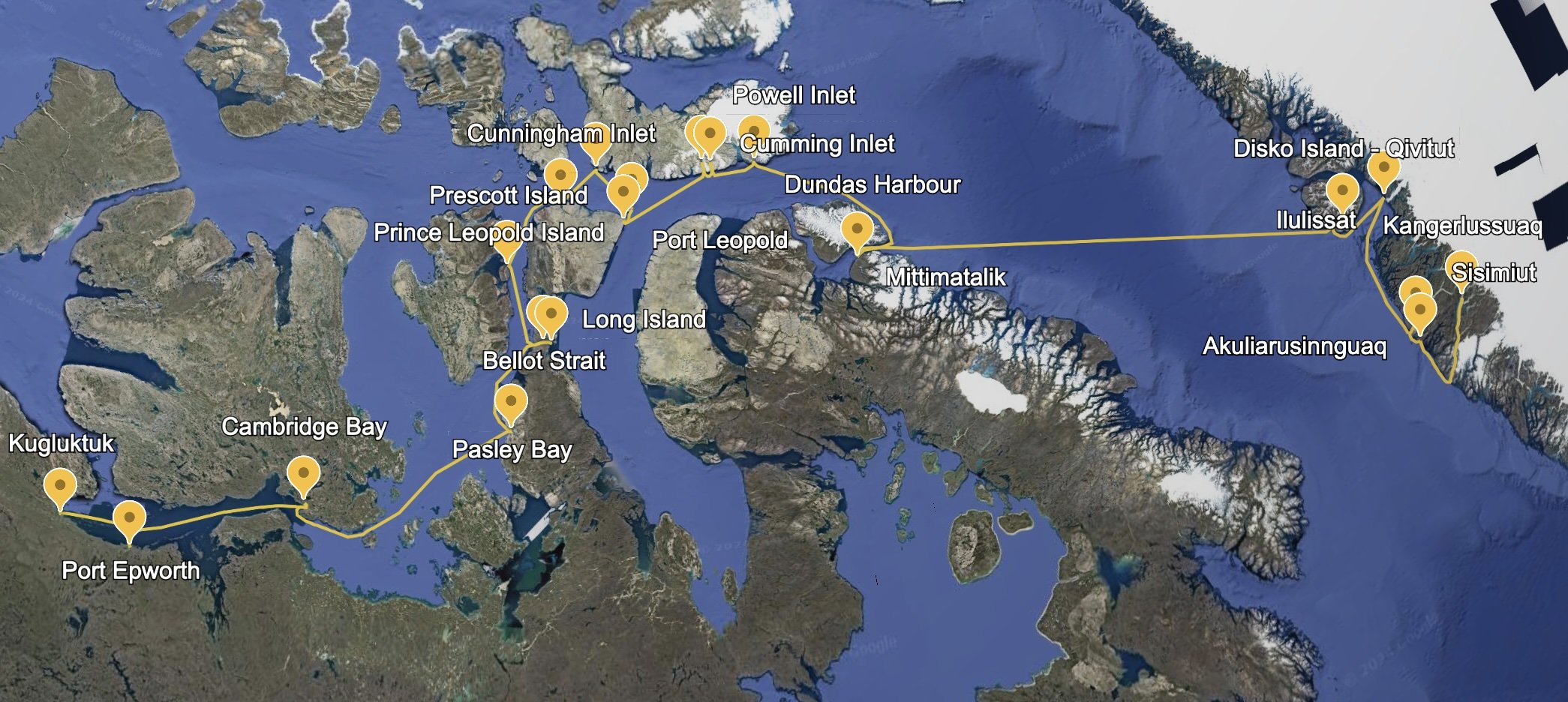
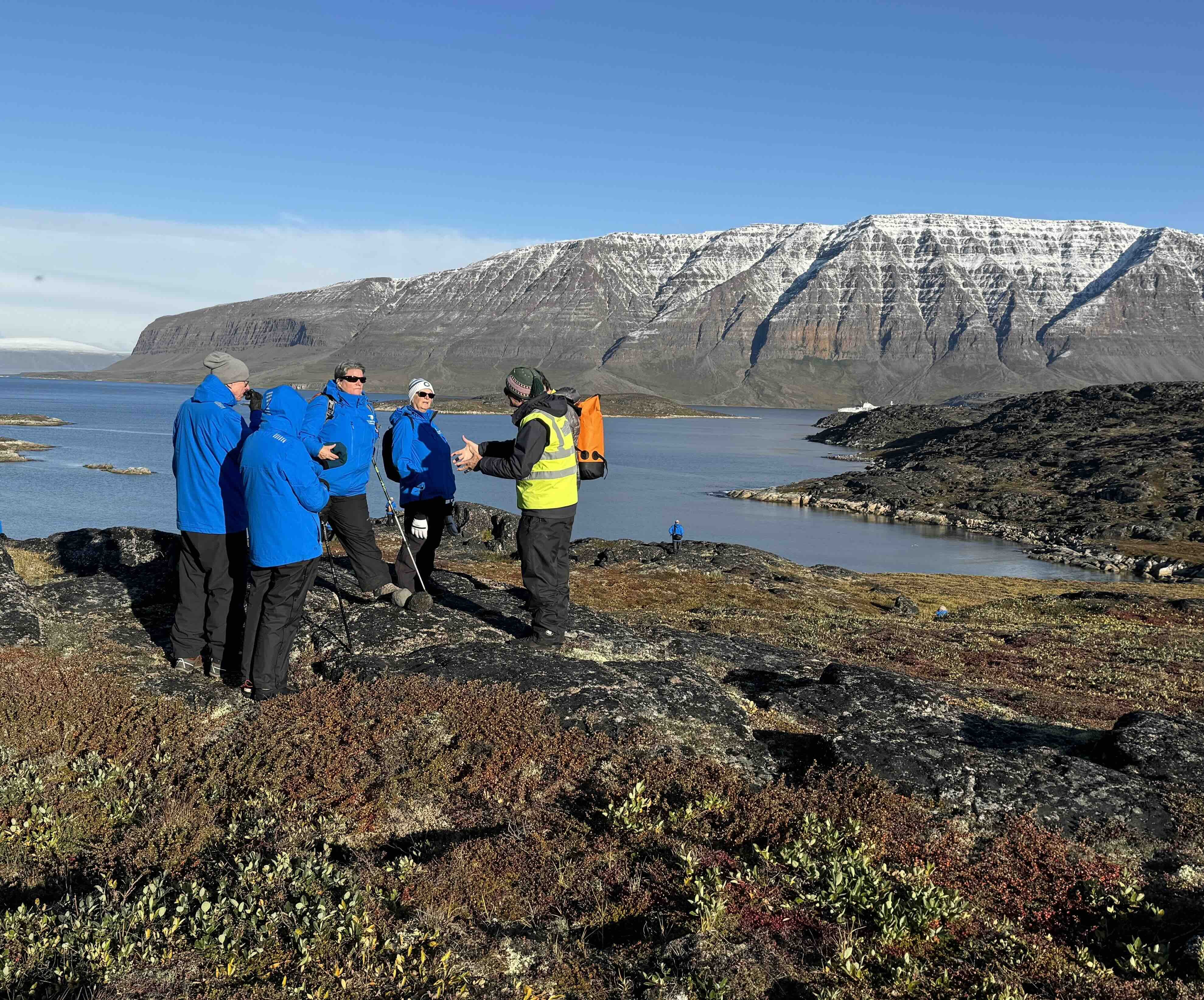
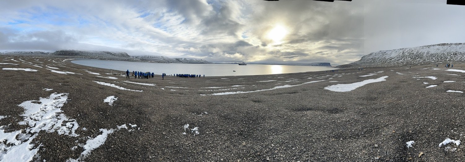
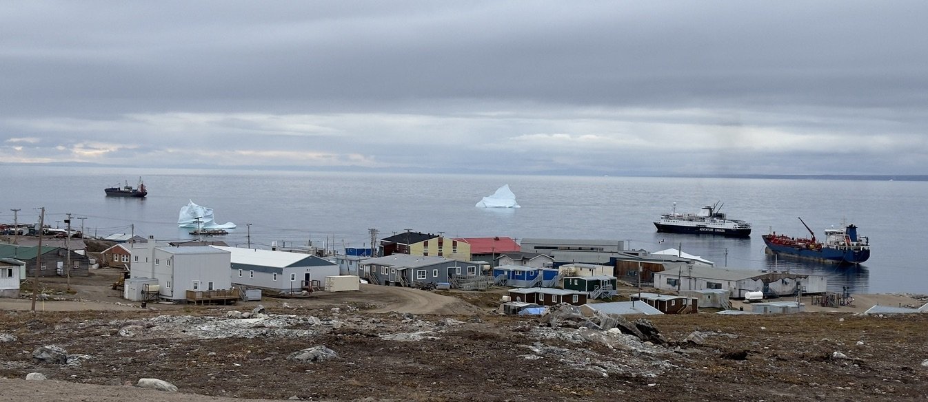
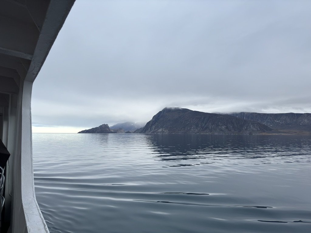
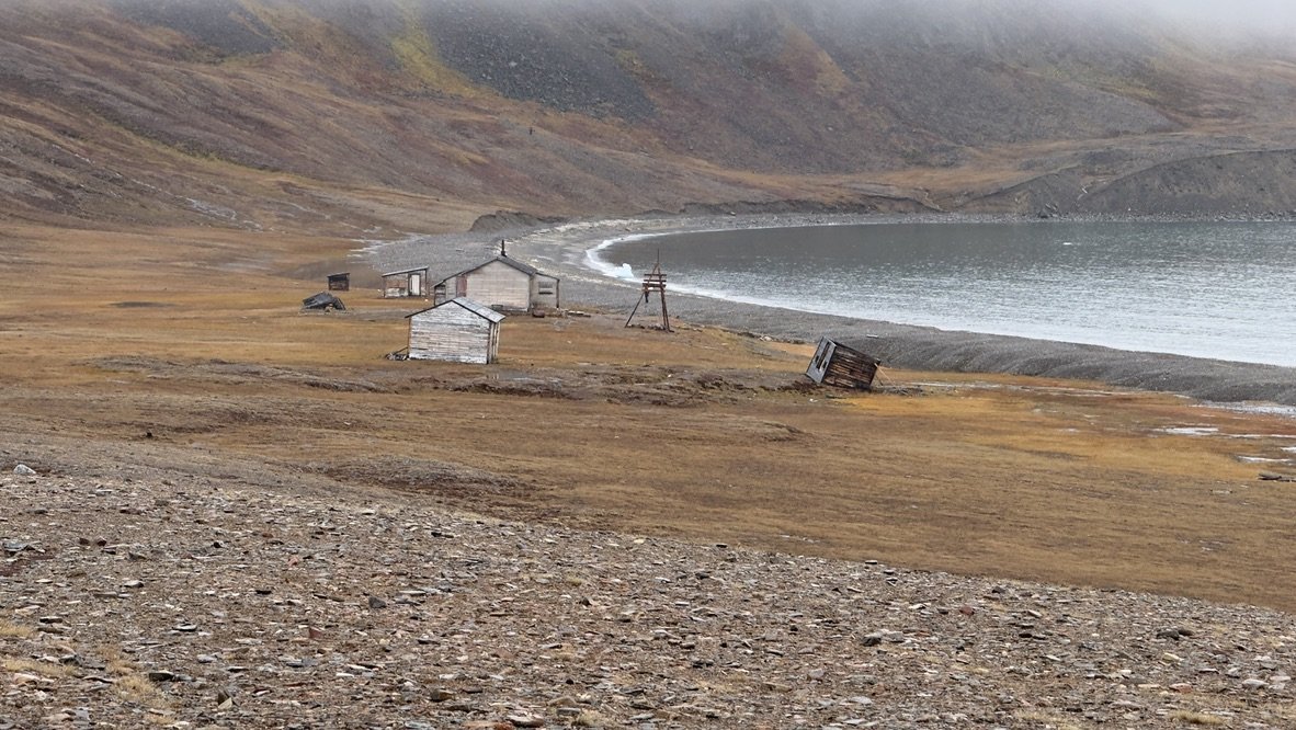
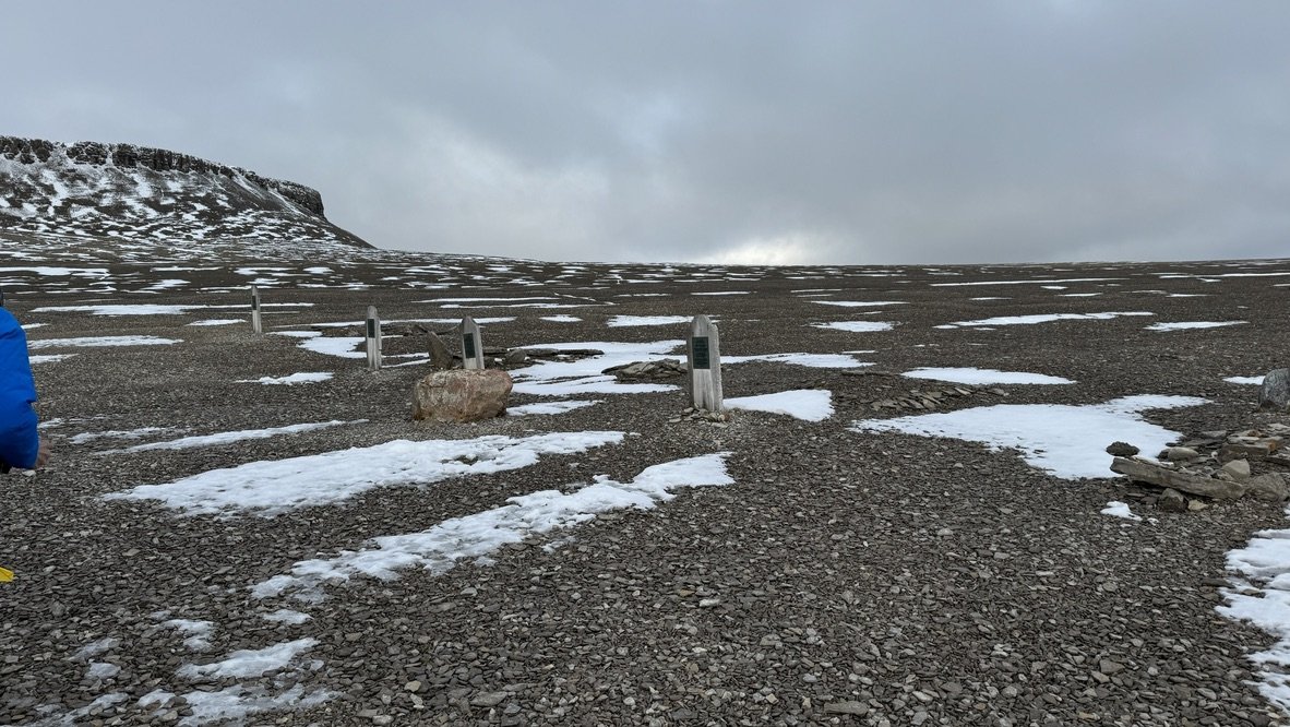
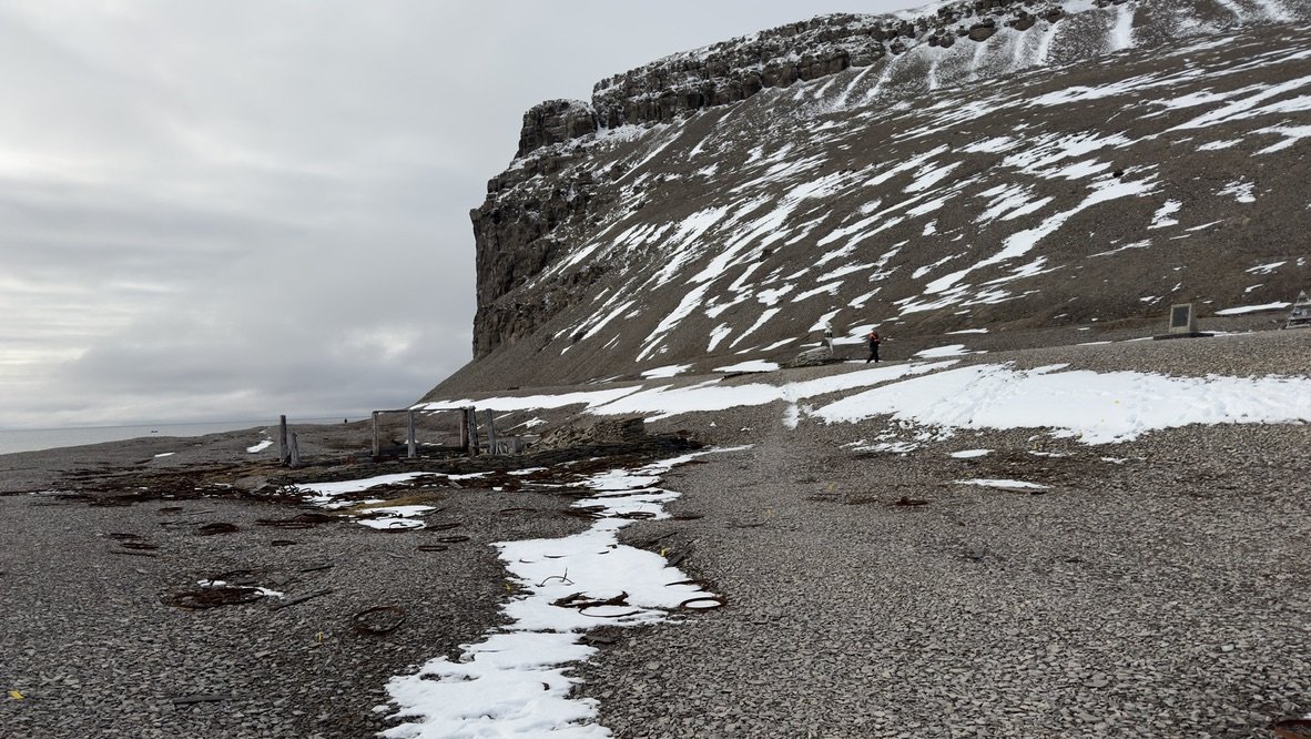
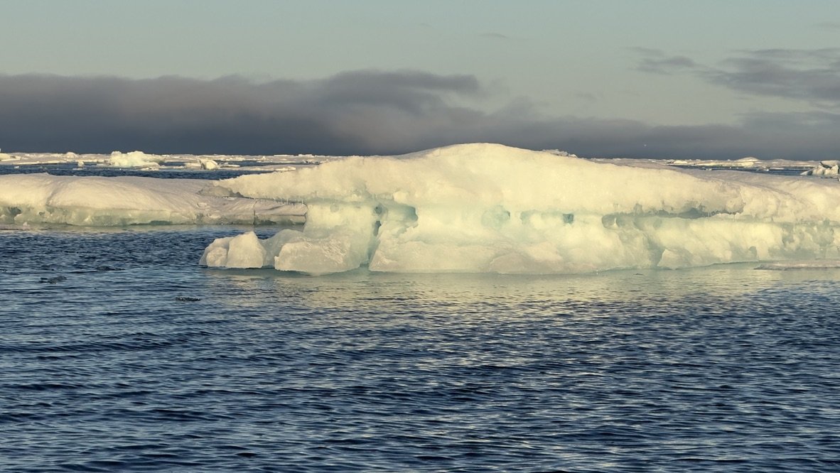
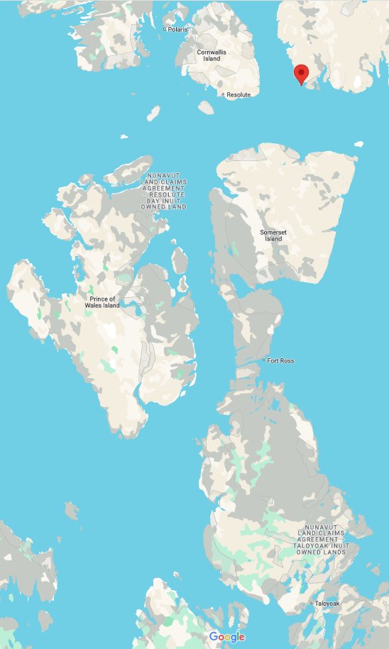
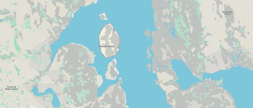
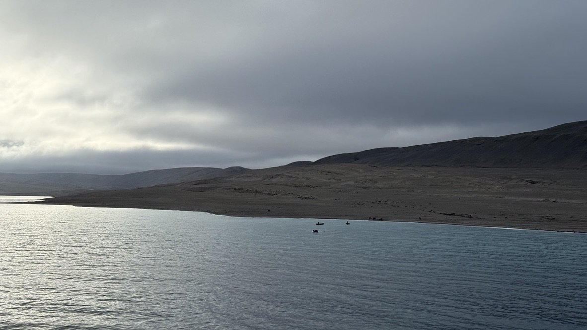
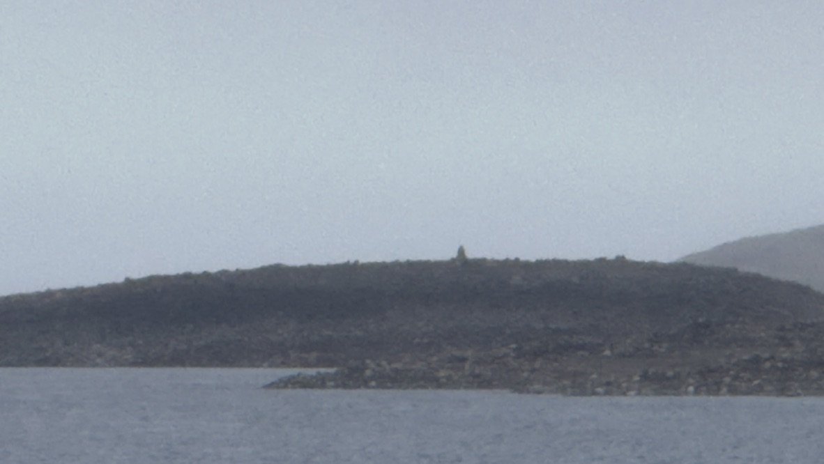
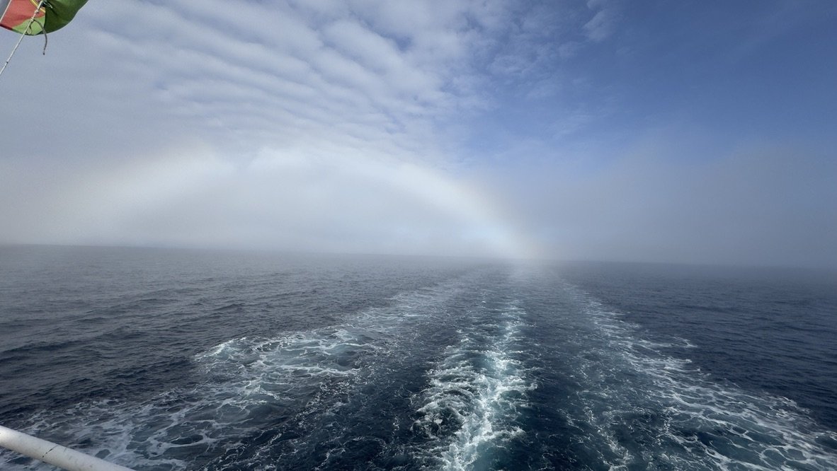
04 My transit of the NW Passage I won’t try to tell the whole story but will at least include a few images of my tracing the route of the Franklin Expedition through the NW Passage this August/September. 1. here is copy of the total route we took. The trip is managed extremely well by Adventure Canada... Greenland We started from the airport 100 miles up the fiord at Kangerlussuak. Ports of call included the towns of Sisimiut and Ilulissat. We also had a stop on Disko Island. We know that the two vessels HMS Erebus and HMS Terror took on supplies from a supply vessel at Disko Island, a common port of call for whalers and other explorers before heading either north to Melville Sound or straight across Davis Strait. 2 On shore at Disko Island, we were with our geologist, as he explained another episode in the evolution of the arctic. He turned out to be a critical part of this story. Baffin and Devon Islands 3 We crossed the Davis straight and landed at Pond Inlet. This town is there for a former airbase, now an airport, at the north end of Baffin Island, as well as the large Iron mine in the region. This view is the Pond Inlet overview looking north toward Bylot Island. 4 here is the NE corner of Baffin Island. This location is often mentioned as a rendezvous site for the Franklin follow up exploration fleets, whaling fleets etc. 5 We rounded Bylot island to enter Lancaster sound and reached Dundas Harbour. Dundas Harbour is where in the 1920’s RCMP officers were stationed, so that Devon Island would be considered occupied. They did not do well as two were dead when the replacement vessel returned three years later. 6 Running to the west, we stopped at Beechey Island. Beechey Island is the known last winter encampment of the Franklin expedition. Here are the graves of three of their members and one for a rescue party sailor who died years later. 7 As one of our team leaders suggested, only a British admiral would have considered that this nice, protected harbor would be a great place to winter. One would be frozen in for 9-10 months where there was no vegetation nor food of any kind. There were polar bears that were hunting seals out on the ice, and that was it. 8 Several years later, a wrecked schooner at the north end of Beechey Island was demolished and used to build a Cache by Hudson Bay Company and called Northumberland house. It was intended both for any Franklin rescue/ searchers or others in need. Franklin’s route 9 we ran into sea ice traveling west from Beechey Island. We enjoyed a wonderful sunset zodiac outing with great photo ops. 10 here is the map showing the mystery of the southern route taken by Franklin from Beechey Island . The Peel sound was often full of Ice as was the Bellot strait. The mystery is how to get to the point NW of King Williams Island, the point of Franklin’s final capture by old sea ice. There are many theories of what route was taken after leaving Beechey Island. One thing I learned is a study now underway by Parks Canada and the geological institute in Ottawa. The annual diving now taking place on HMS Erebus is focused on the damaged side of the hull that is slowly being crushed and is slowly collapsing. It is the naval officer's cabins being searched now, because the scientific officer's cabins are in good shape, and will be explored in later years. There are only about two weeks of diving each summer, so time is of the essence. What was found in these naval officer cabins is a surprise; it is a collection of 16 rock samples. These samples are being analyzed. Let’s wait for the actual scientists to publish their findings, but the short version is this tale. The geologist on our cruise is the geologist doing this study. He can take a rock sample and identify which coastline of which island is the source. Thus if the sailors collected souvenirs along the way that is a way to trace the route….hold that thought. The ice this year was different than the last few years. The tour normally travels south down Prince Regent Inlet and through the Bellot Strait. This year we went up around the sea ice we encountered and sailed down the Peel Sound into the Franklin Strait. 11. On the way, we landed at Prescott Island just off the east coast of Prince of Wales Island. It as a first time ever landing by Adventure Canada, our Expedition team. 12. Not only were there hundreds of Beluga whales there, but we also found a distinct red rock. Our geologist cut out samples for the study. [ obviously he is allowed to do so…smile] He also predicted that this new sample will match one of the 16 samples that he knows well…….wow. we were there when he found it! I can’t wait for the next Parks Canada publication on their progress. The tour then made two transits of the Bellot strait. 13. Here is the monument showing the northernmost point of continental North America, halfway through Bellot Strait. Yes it is further north than Alaska! The finding of Franklin’s route 14 Later that afternoon we were cruising along headed for Cambridge Bay on the south shore of Victoria Island and we crossed the straight where HMS Erebus and HMS Terror were [pinched] stuck. We saw no ice whatsoever! What was great was in mid afternoon, we saw a fogbow….how appropriate. The tour ended in Coppermine, now Kugluktuk. A place of much history, but for another day. I look forward to getting back into this build. More house guests just left, so maybe next week. Cheers Jon


- 62 replies
-
- 10
-
-
- Arctic Exploration
- OcCre
- (and 2 more)
-
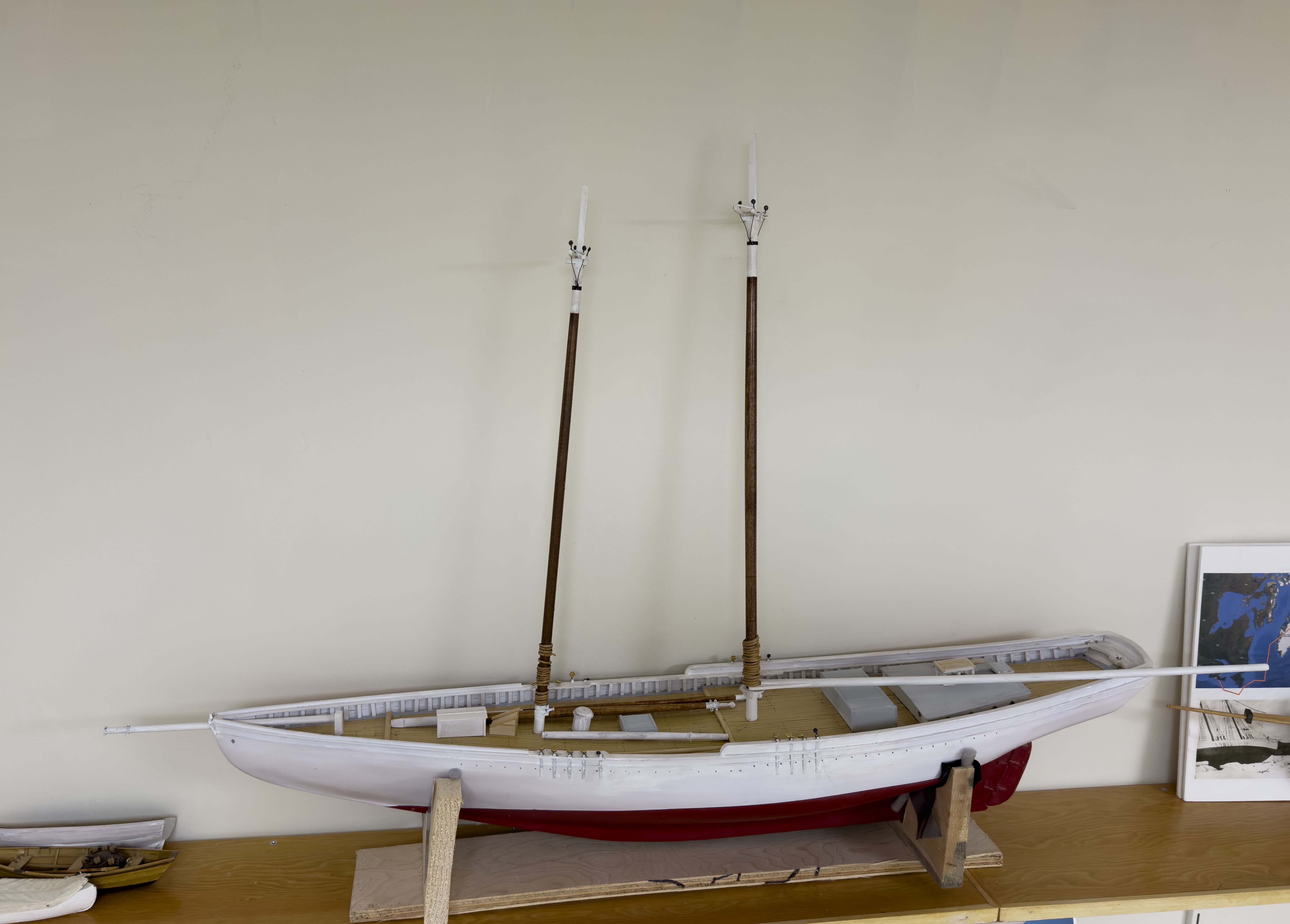
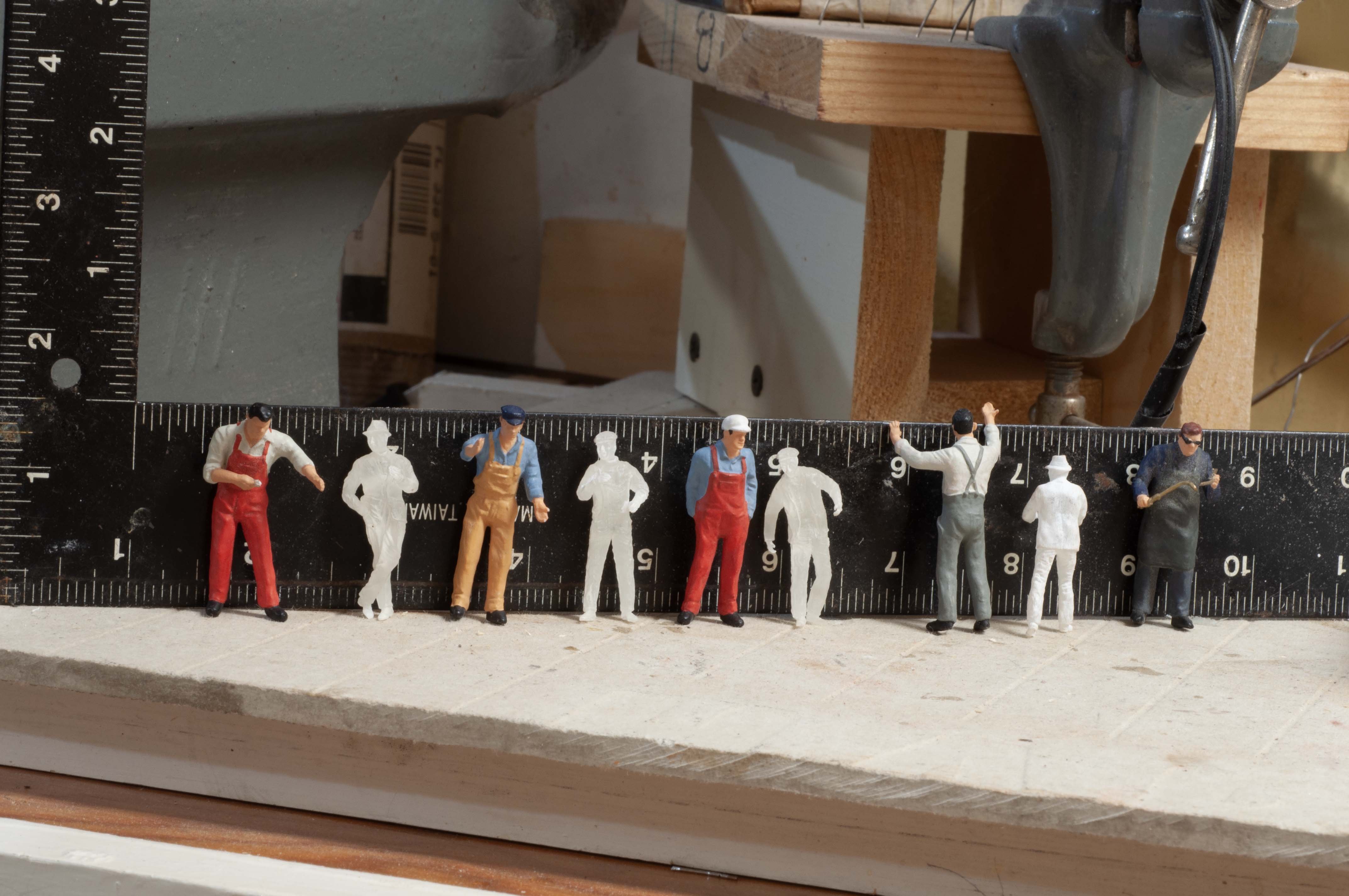
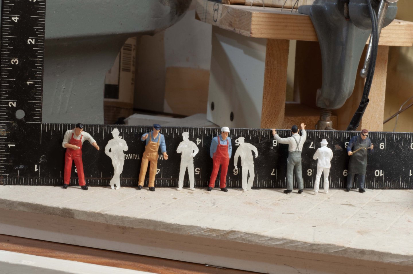
2 get started with step one Looking Back first to the Charles Notman build there are a few images to tell her story of the past few years. 1 here she was sailing in the local West Harbor Pond 2 here she was during the winter after retiring from the sea, getting all the rigging added that could not be in place if RC sailing. 3 here is the image of my finding that the painted figures I had bought placed against the clear Shapeway 1:48 printed figures. It is easy to see the painted figures were too tall for 1:48. Now however they will be perfect as they return to the smaller schooner at a recalculated 1:40 scale. I just need to find them and sign them up. Now to work 4-5 here I laid her out on the shop bench as I was leaving for Canada. 6-9 here my daughter and friends painted the hull as I ventured through the Northwest Passage. Now that I am really committed, I set her up on the bench and looked to what had to be done. It was now that I made the decision as to which vessel to emulate. 10-11 here we see Charles Notman’s unorthodox design, where the poop deck carried forward of the main mast, was interrupted till the fore mast and then resumed as a raised foredeck. It was not very strong to say the least. 12-14 shows today where step one is partially complete. I have demolished and rebuilt the fore cabin structure and added deck framing for the raised deck. I also extended the base for the balustrade. Next up is the decking. When the material comes, I will work on how best to remove strips and nest the new planks in. Hopefully I can pull it off. I will also use the photos I have to make the outside cladding of the fore cabin and add the roof deck. All for now
-
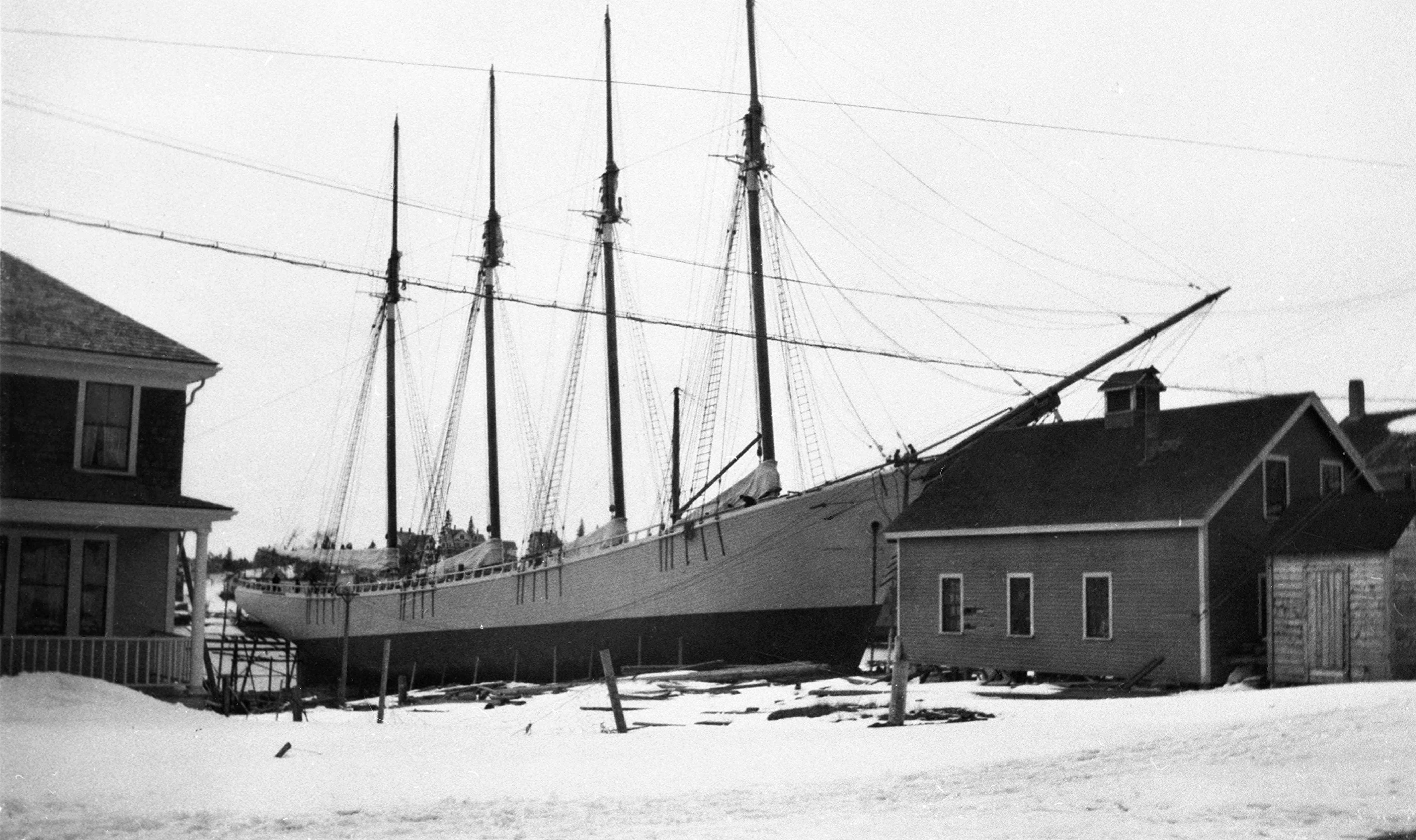
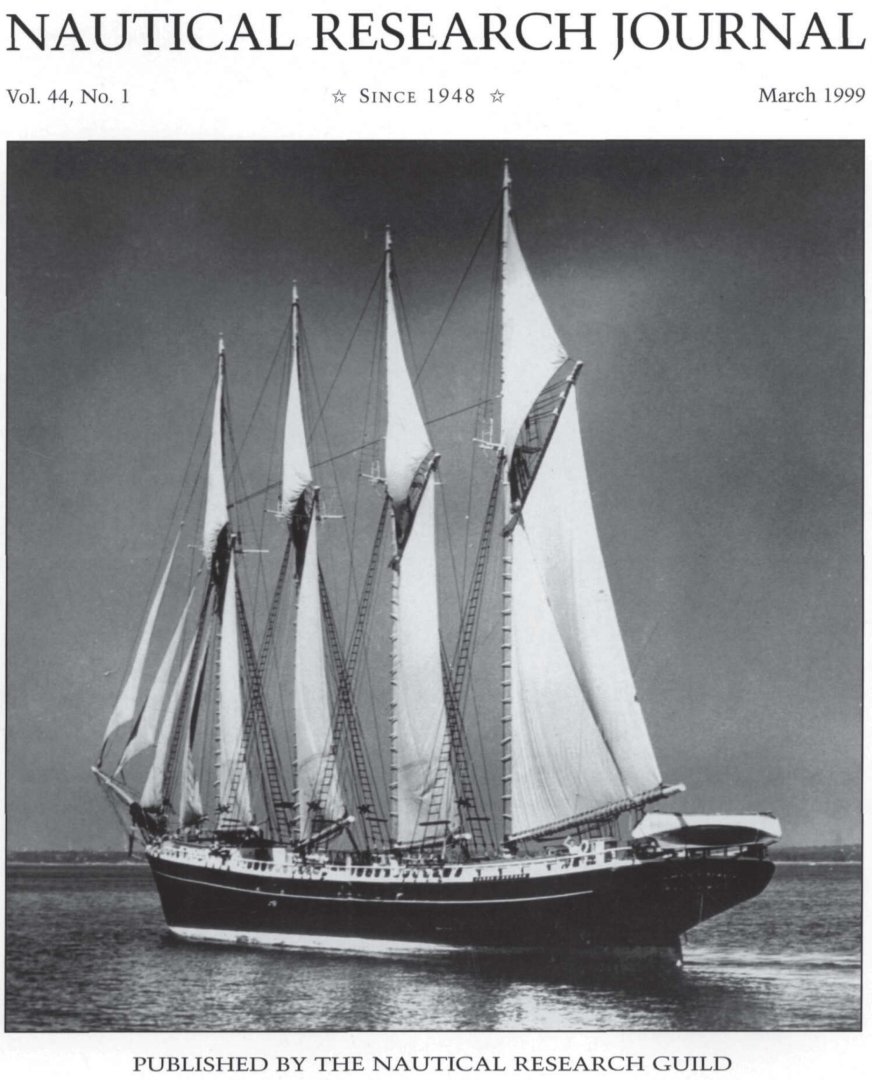
Re-Build for Zebedee F Cliff The beginning This build is a retrofit of a previous model. The story follows: Back in 2001 I built my first ship model of this end of my career. As a teenager, I built several plastic models of the typical range, HMS Bounty etc. The first model in this century was a pair of 50-inch Marblehead RC sailboats started at the Wooden Boat School in Brooklin, Maine. My son and I did the basic hulls in school that summer, and I finished them as a pair and we both sailed them a few years back. I decided to build historic vessels in the future and to make them sail. Most of this story comes out in my Charles Notman, BHYC One design and Bluenose 1:24 build logs that spanned up through 2015. Since then, my focus has been on the local scene, as I continue to study and find the maritime history of our peninsula more than enough for my lifetime. While preparing to build Charles Notman, I was working with the late Jim Hunt. He taught me that there were no surviving plans of any of the WW I era Boothbay schooners. He also noted after his study that the high shear in some of the Boothbay Schooners was unique. He too opted for a Bath designed schooner for his model. At the time I thought it was better just to copy the plans and build Charles Notman, a Bath Schooner of similar size. 1 Jim Hunt published NJR article on the ten Boothbay Harbor Schooners of the WWI era. Note: there were two others built in East Boothbay 15 and 20 years earlier. This summer while my daughter was visiting, she agreed with me that I should re task the schooner to be a Boothbay Schooner. I went north to travel through the Northwest passage so she house sat, kept the dog and took the first step. She painted the hull of Charles Notman white, as the two potential Boothbay schooners built in 1917 -1920 were both white. So, when I came back, I was committed. Choose which schooner to build. There were two yards in town. One was called the East Coast Ship Company on the east side of the harbor and the other was Atlantic Coast Company on the west side of the harbor. One of my recent builds was the Ada Cliff built by the East Coast Ship Co. So I started off favoring the Atlantic company. The vessels were the Bradford F Jones built 1919 by Atlantic at 221 feet 1600 tons and the Zebedee F Cliff built 1920 by East Coast at 206 feet 1361 tons. The current hull of Charles Notman is supposed to be 219 feet and 1518 tons. Therefore, she sits between. The deciding issue though was not the size but the deck profile. 2 -3 here is a deck completed on Mary Bradford Piece built right after Bradford Jones by Atlantic and a view of Bradford Jones mid deck area framing while under construction. It seems on this deck profile the mid deck section is about 3 feet lower than the fore deck. The balustrade is only on the aft section behind the mizzen/spanker mast 4 here is a thumb nail of the great photo of Bradford Jones nearing completion. There are several more of her after launching. She had a normal life until many of the local schooners were retired in about 1930 and she was sold to Portuguese interests in 1931. 6-7 here we see a view of Zebedee F Cliff from land side nearing completion and a second view of her at the wharf sometime after launching. Note the Balustrade going forward past the foremast shrouds. This profile means a flat deck throughout. I have similar views of other East Coat schooners, and they are the same. The Zebedee Cliff life was more interesting. Like others she retired and sat in Boothbay starting in 1930. There are many surviving images. She was laid up for a while in Eastport and then sold to a firm in Portland, Me in 1938. In 1942 she was sold to the navy, broken up and sunk as submarine protection at Portland harbor. I will share photos in the next posting to show the unusual and unorthodox deck profile of Charles Notman. The Poop deck was brought forward all the way to the main mast. The upper deck was then omitted til forward of the foremast where the fore deck continued forward. Understanding the broken truss design one quickly sees why this unorthodox design was not carried forward after 1894 when Charles was built. · To emulate the Bradford Jones design……This task would require depressing the main deck roughly ¾ inches and removing the balustrade back to the mizzen. A major undertaking · To emulate the Zebedee F Cliff design… This task means demolishing the fore cabin then filling the main deck and rebuilding the fore cabin. There are minor alterations to raise the foresail. Then the balustrade needs to be extended forward past the fore shrouds. A more manageable undertaking For some reason that I cannot image at this time, the length on deck of the model I built 10 years ago is 60 inches. Using 1:48 or ¼” to foot that means my model represents a 240-foot schooner. OOOPS! So, I must declare that when I do my model of Zebedee F Cliff, it will have a few dimensional flaws. One solution is saying the scale of the model is 1:40 or close to 5/16 to a foot. Despite that clarification, the effort shall be to represent the largest and final schooner built by East Coast Ship Company. Humorously I have figures that were sold to me on line from Europe that fit that bill. They showed up in many images of the Notman build before I realized these guys were 7 feet tall in 1:48. They now have a new home. There won’t be many updates to this build. I reference the original build of the RC schooner Charles Notman for all the previous work. There are three grouped tasks: · Complete demo, deck and cabin structure [sort of done now], and complete the new decking[ on order]. · Complete new fore deck house and complete detailed hull painting/ transom work. · Complete new balustrade, raise foresail and reconnect rigging. Off we go again. My two other current builds are comfortable on the shelf for a little while, let’s see if I can get this one done before heavy leaf blowing. all the photos 2-7 here are owned by Boothbay Region Historical Society. Happy first day of fall


-
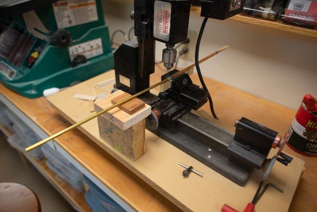
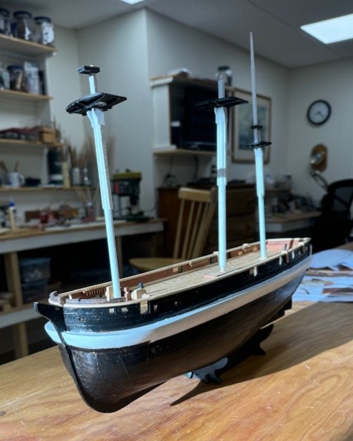
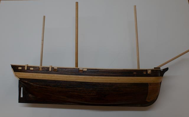
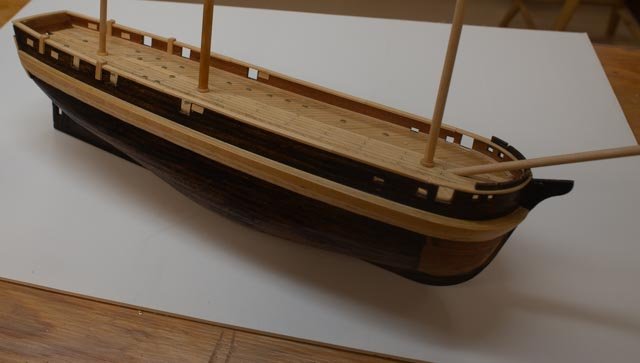
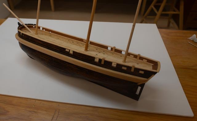
03 Finish the hull My goal has been to get the hull basically complete before heading north. I completed the kit photo instructions for pages A-E , so here she will rest for a while. In the update photos we see a little of the process and then how she is today, as I have put her on a shelf. 1 -3 getting the ice channels sanded and shaping the cap rails by soaking and then clamping them to one side of bulwarks to dry to shape. 4 -6 the rails are on and a coat or two of poly rubbed in. In this photo I thought I was done. The kit masts are just loose in the “holes”. I am also sitting with all natural wood. Not sure yet how far that will go. I checked the kit instructions and found one more item to complete sheet E and that was the simulating mast boots. Before adding them, I recalled much discussion on earlier logs that the kit supplied masts were too small, so I and went back to those logs to check. Using USA numbers, I switched to get close to the 7MM bow sprit and foremast, 8 MM for the main mast and 6 MM as supplied for the mizzen. I reduced the stepped section to fit the existing boots and “mast hole”. I am sure there is a more elegant name for it than mast hole! 7-10 here are 4 views with upscaled mast blanks using a white back drop to see if I can get a better feel for the dark colors and how they will play versus the black and white paint option. As I’m an amateur photographer, I suggest…no I can’t. I suppose some side lighting would have helped. Anyway, I hope to have a great adventure in the Canadian Arctic. I see online that the ice is not yet out, so not sure what will happen and how far into the passage we'll get. At least I will have a fun memory with HMS Terror sitting on a shelf. Happy summer
- 62 replies
-
- 5
-
-
- Arctic Exploration
- OcCre
- (and 2 more)
-
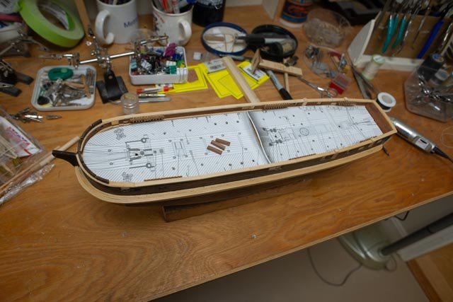
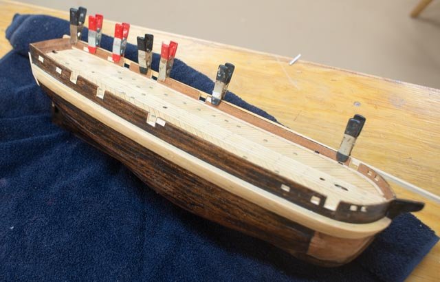
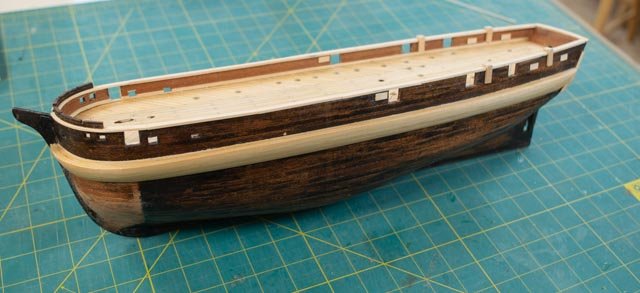
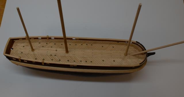
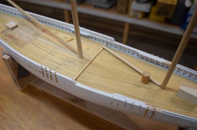
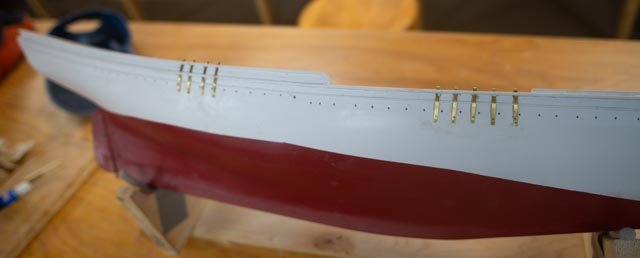
10 oops rework the deck based on review of photos I mentioned above a dumb move / oops. I was in a hurry and somehow laid out both masts incorrectly. Based on that layout, I shaped the rails and included the pin rails. I took the model to the garage, so I could peck away each day a bit while summer guests made working in the shop not convenient. I posted the installed decking. I should have just waited. Here is the sequence….. 01 returning to the shop, I proceeded to carry on and installed all the chain plates. Dumb! Back at my shop computer, which coincidentally I replaced my long-gone computer at this same time. We all know that resetting a new computer means another week that I should have waited. I finally resumed studying all the available images to figure out how the deck was laid out. As I mentioned earlier through the net I found the several collections in both Gloucester and Boston Library collections. I “borrowed thumbnails” and blew them up, scaled spars etc. I had previously shared the sail plan that I did in cad months ago based on a broadside racing image. Why did I not use that drawing when I located the Mast? Who knows 02-05 In these photos one can see the relocated masts and re-laid decking. The foremast wrong hole is amazingly close enough to the round fish loading hatch with which I will plug the hole. The main mast hole was plugged and covered in new decking. The pin rails and chain plates were all relocated and are back together. At some point I need to do more remedial work, especially the outer hull where the chain plates were removed. The pin rails will be mostly covered with coiled lines so they will work out. Going forward Photos 6-8 To plan the deck work, here are two cropped images that come from different internet images and sites. When blown up, they give a reasonable sense of what was on deck and where. I also have one of our Historical Society photos of the sister schooner Louise Howard. The similarities carry through after scaling and measuring the sail plan. So they both confirmed the error made and after the fix I am ready to move forward. cheers
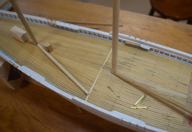


-
Thank you Rick and Keith for you comments. I just had a set back as I was reminded that haste may cause waste. I had hurried up to get to a point to move the model to the garage while summer quests were here so I could continue and install the decking . In that rush I made a big oops. I had mis located both masts. I am part way through the fix and I must say it is an ouch. I will post in a few days when I figure where I went wrong. My not having drawings did not help but I do have enough pictures , so it was me in a hurray cheers