
JerryTodd
-
Posts
877 -
Joined
-
Last visited
Content Type
Profiles
Forums
Gallery
Events
Everything posted by JerryTodd
-
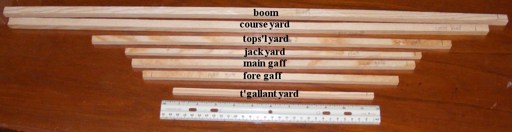
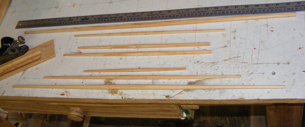
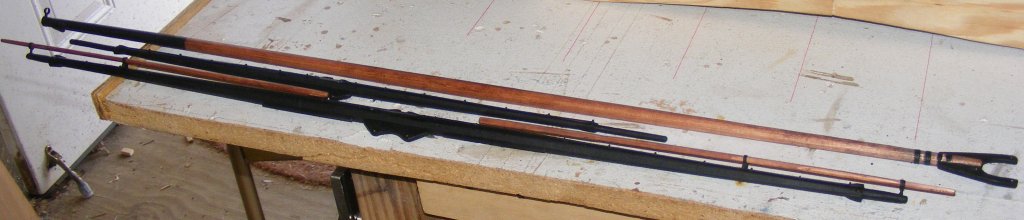
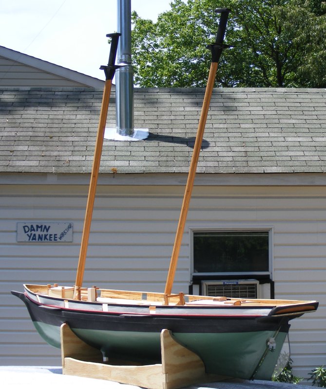
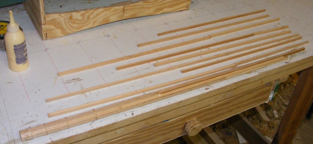
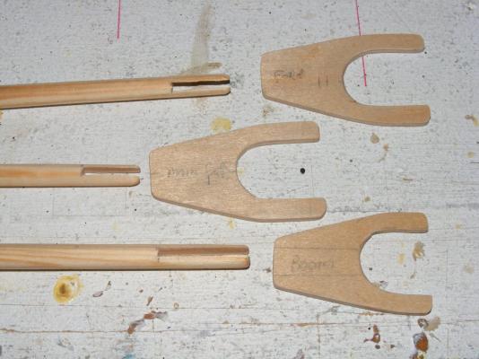
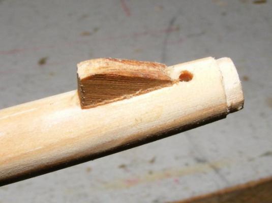
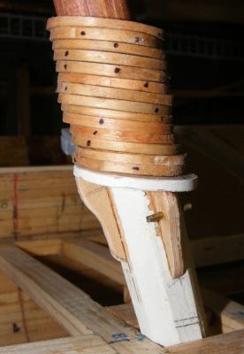
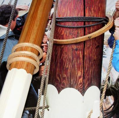
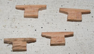
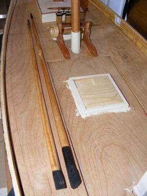
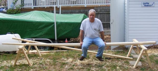
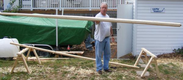
 Spars All the spars were made of white pine, since it's been working so well so far. Rough cut to size, square stock was made 8-sided, etc, etc, to round. Gaffs and boom were fitted with jaws made from aircraft plywood and tried for size. The boom has a shoulder cut in the end for the ring-tail iron and a bolster that keeps the mains'l clew out-haul held off the boom. The main mast was fitted with a saddle and knees for the boom to rest on, after the mast's hoops were loaded on. All the spars got stain and paint, and all the brass was blackened and painted. The coarse yard got stuns'l boom irons, stuns'l booms, and jack stays. Cleats and holes for sheets and the like... and a clew iron for the main boom The yards and boom
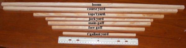


- 79 replies
-
- 8
-

-
- pride of baltimore
- privateer
- (and 3 more)
-
Bait tub?
-
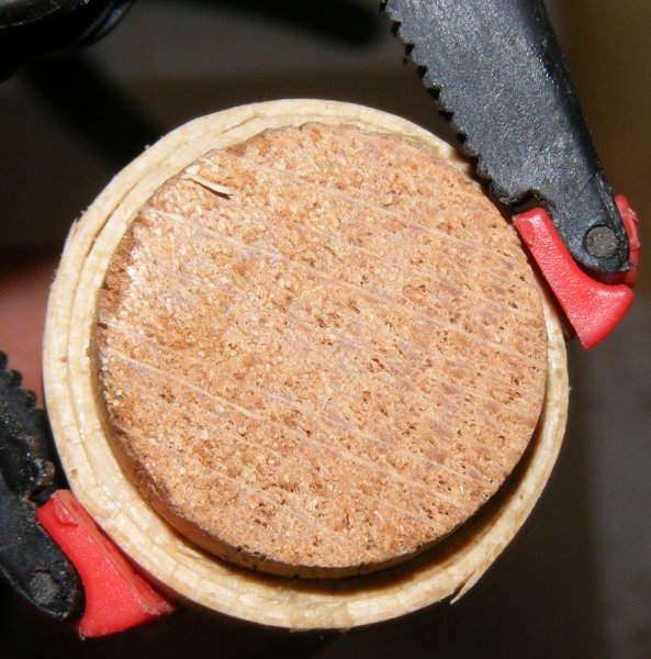
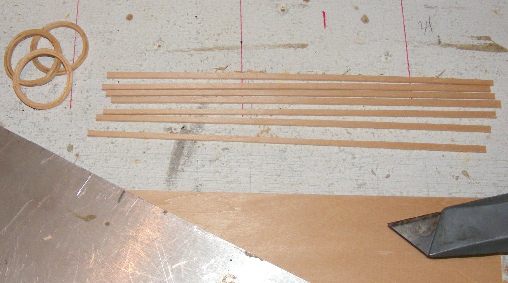
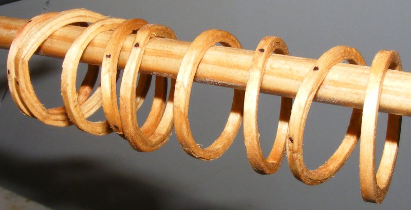
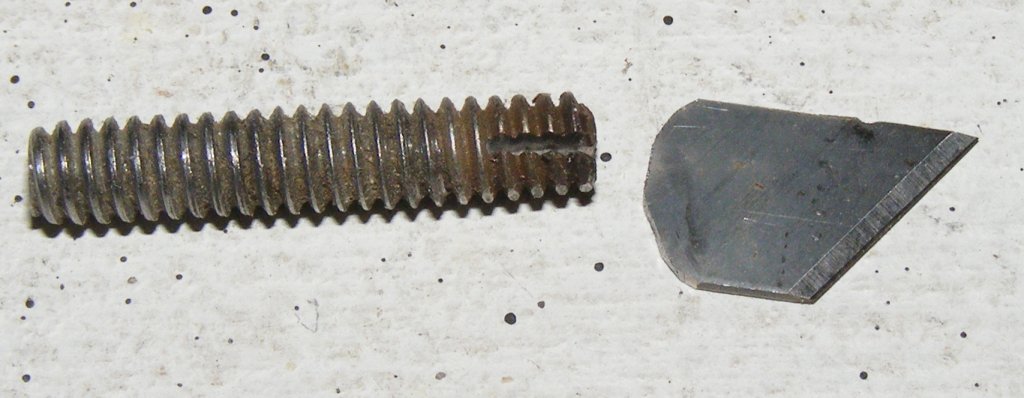
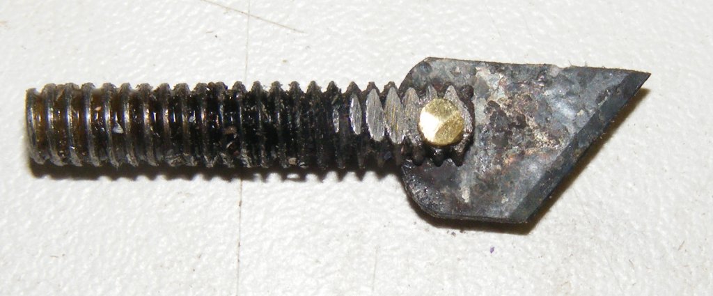
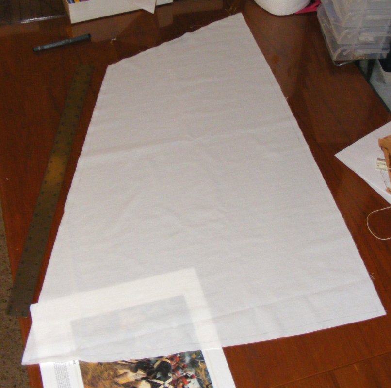
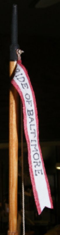
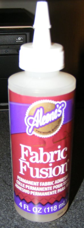
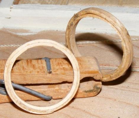
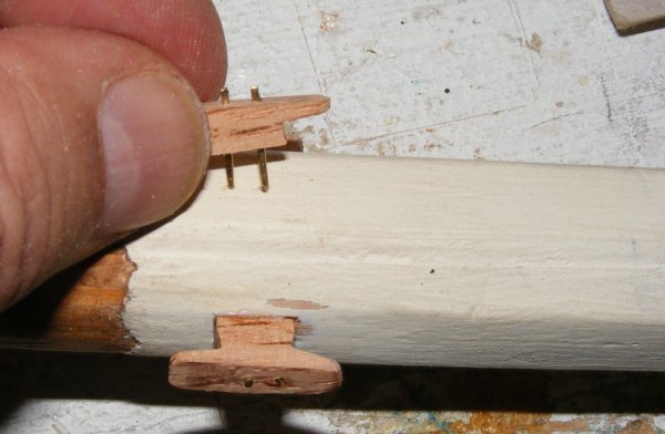
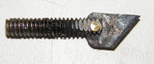
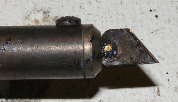
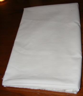
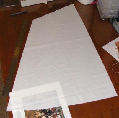
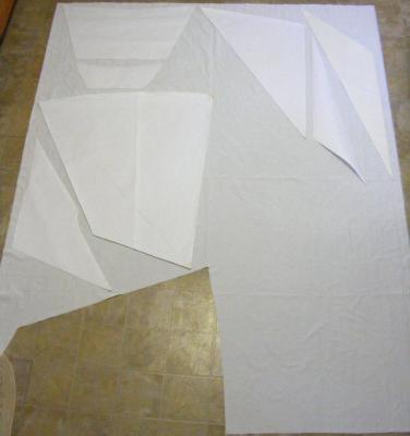
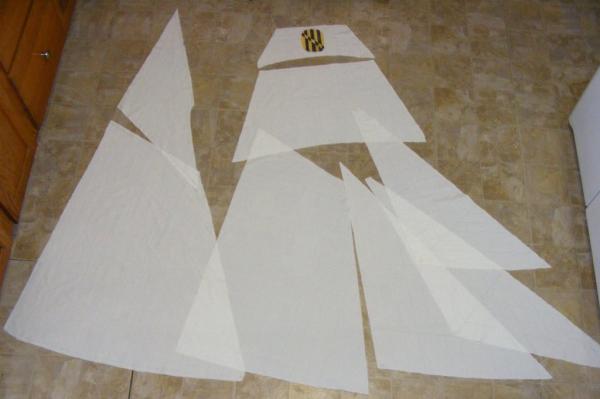
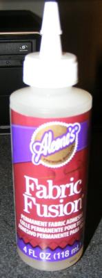
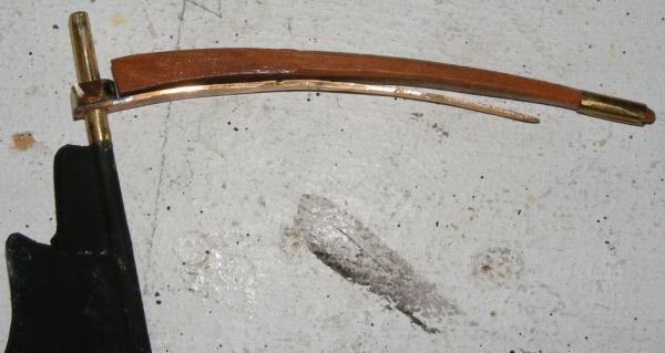
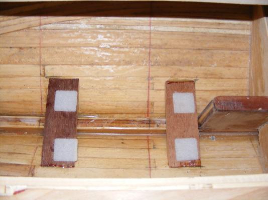
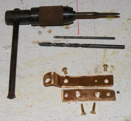
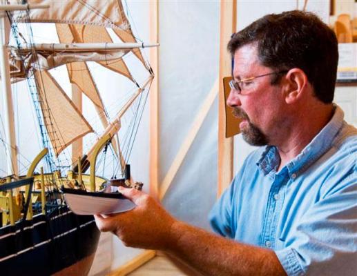
BTW folks: Don't forget you can click on the images in these posts to see them full sized. I took Pease's book to the local hardware megastore and had thier paint department use their color gizmo to create a sample jar of the cream color Pride's inboard things were painted; the sides of the cabin, hatch coamings, base of the masts, and eventually, inside of the bulwarks. This ran about $3 US and I should be able to get the color matched easily if I need more. It's funny actually, both the real boat and my model of her will have their inboard surfaces painted with latex house paint. I wondered about what to make mast hoops from. I liked bamboo, but I didn't have any that wouldn't require a lot of work just to get into the right sized strips. Just for giggles, I tried 3/32" sheet bass. Cut it into a strip the right width; shaved the ends down so they tapered to nothing; wet it in warm water; and wrapped it around a 1" dowel. That worked so well I tried another and made a few. Then I precut all the rest of the strips plus a few, cause a couple snapped while wrapping them around the dowel. Once made and glued up, I dipped them in oak stain. I made the cleats that go at the base of the foremast. They were glued and pinned on - after loading the mast with it's requisite number of hoops. Two weeks before, a couple of yards of Supplex arrived for the sails. When I cut out Constellation's sails, it was a pain. To seal the edge of the after cutting it I would run it along a hot soldering iron. It didn't take much, just the slightest pause, to burn a scallop in the edge. This time I resolved to use a hot knife. Oddly, I had a very hard time finding one for my iron, so I made one. I happened to have a couple of copper machine screws in my loose fastener bucket that had the right threads to fit my soldering iron. I drilled a hole, then cut a slot and inserted a portion of an XActo blade. I pressed the slot closed onto the blade and peened a bit of brass rod in the hole to rivet it all together. The first sail I cut with it was the mains'l, and it worked like a charm. There's a little technique to it, but you pick it up fast. When I was researching making one online, everyone said it's best to cut on glass so as to not wick the heat off the blade, so I used an old picture with glass in the frame as my cutting board. I had the knife made on June 2nd, and laid out and cut the rest of the sails by June 3rd. I even made Pride's pennant and that ugly Lord Baltimore eblem they had on the t'gallant sail. The panels were marked on the cloth with a very fine point black marker, just as I had done on Constellation. Other parts of the sails were cut with the knife; reef bands, tabling, corner reenforcing, that ugly emblem, etc. These were applied to the sail with fabric adhesive.


- 79 replies
-
- 9
-
-
- pride of baltimore
- privateer
- (and 3 more)
-
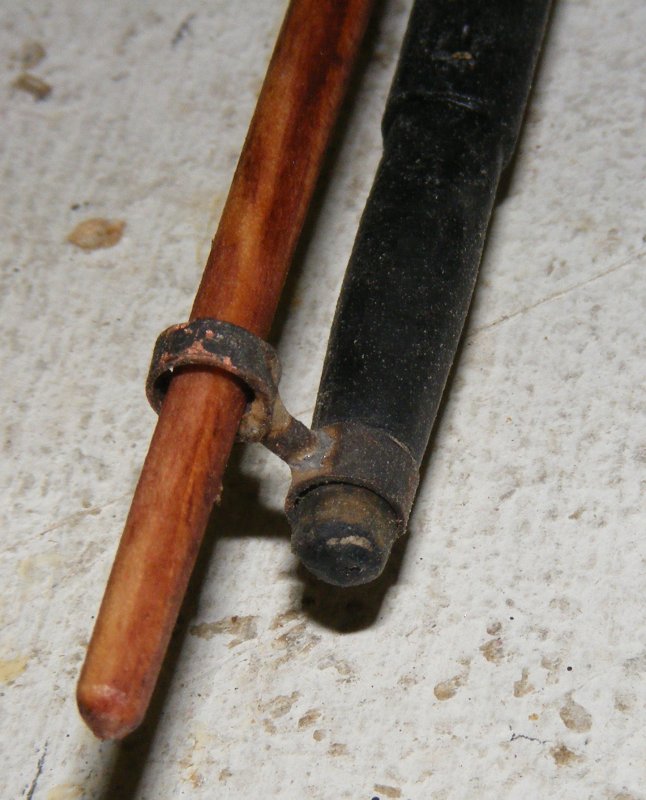
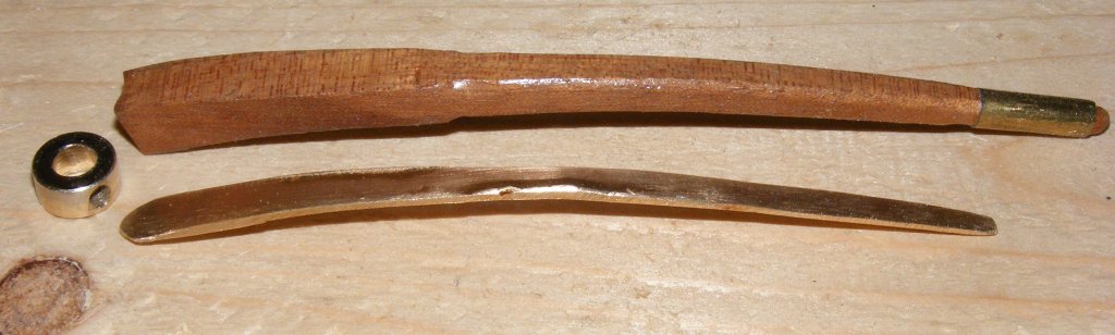
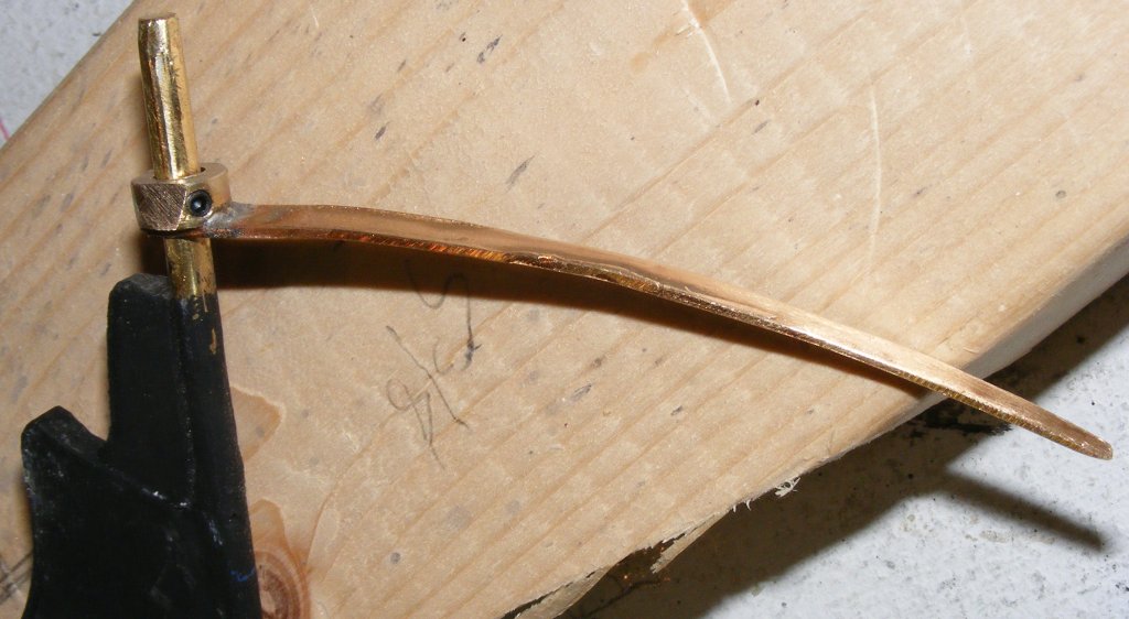
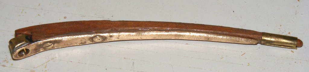
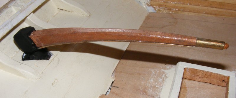
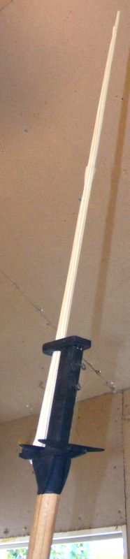
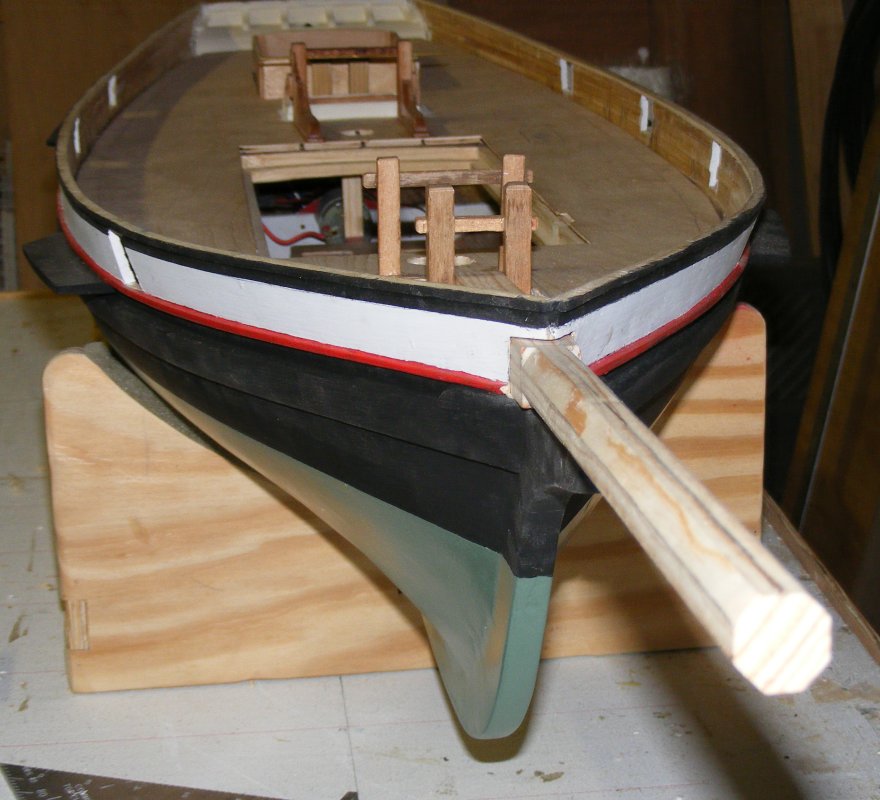
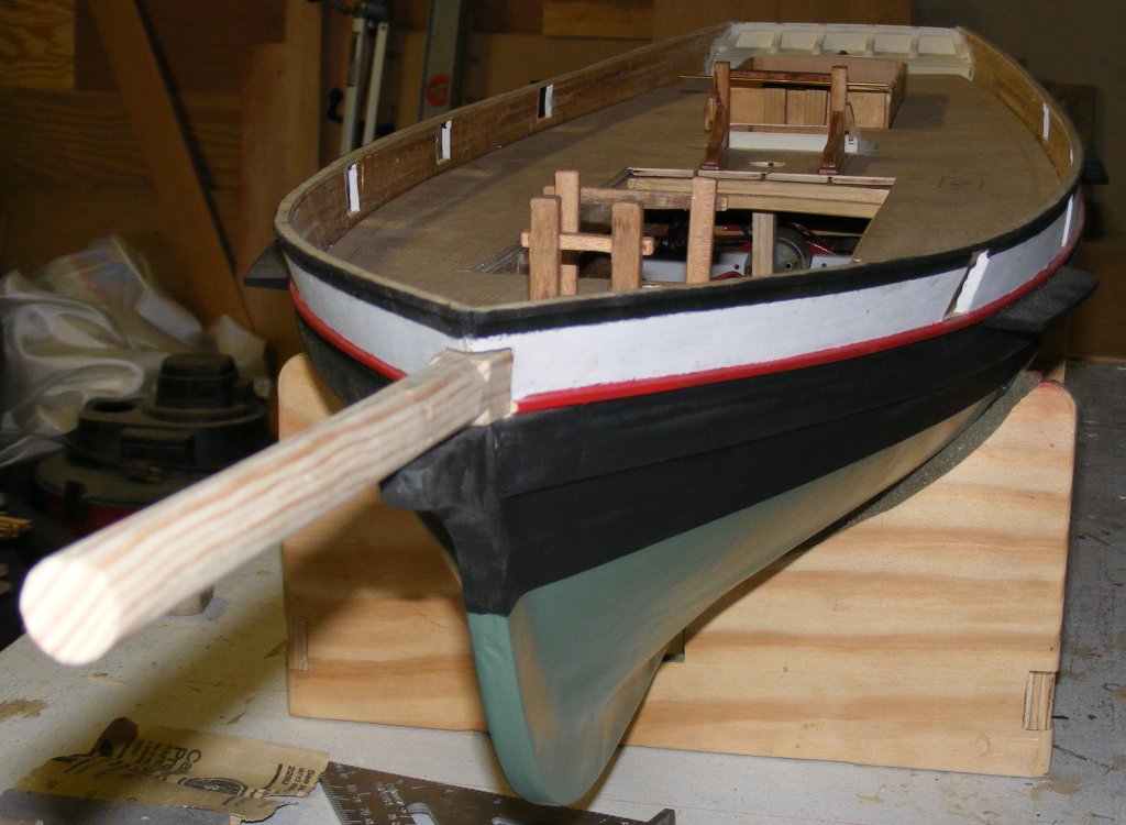
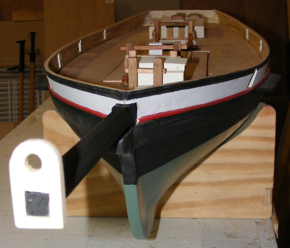
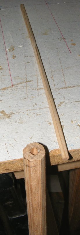
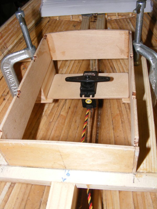
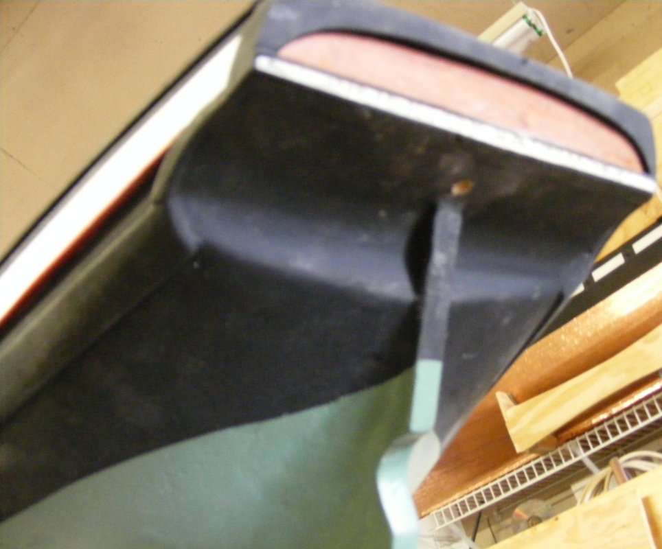
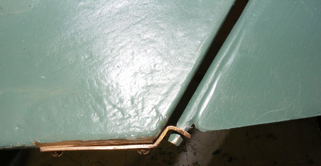
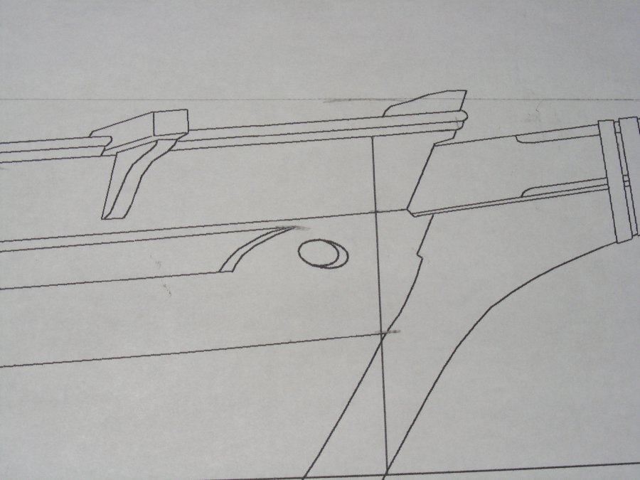
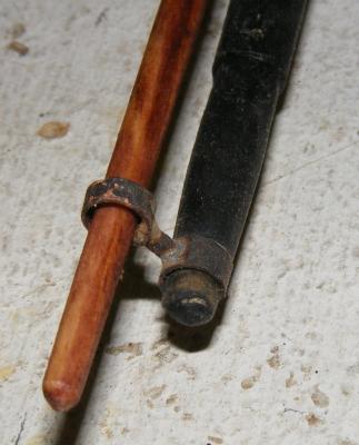
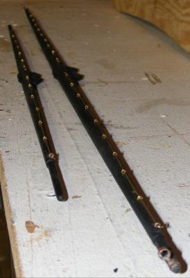
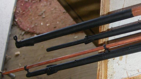
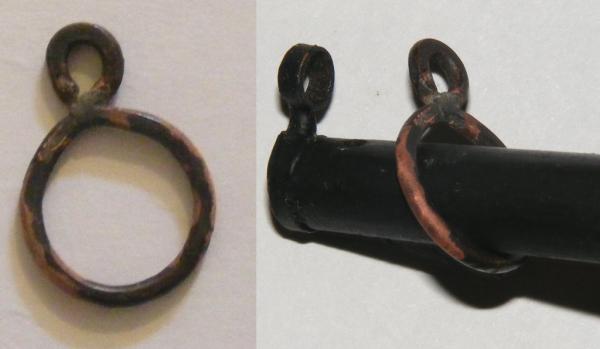
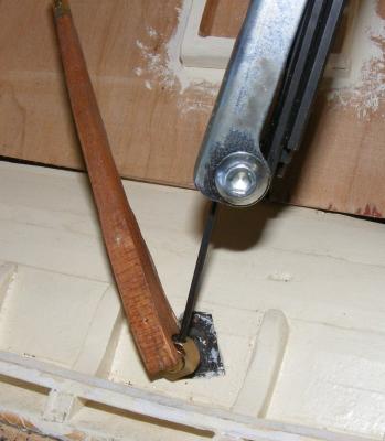
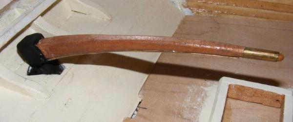
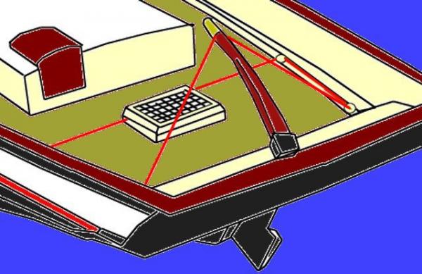
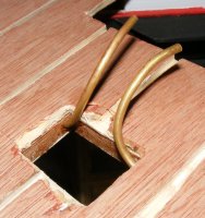
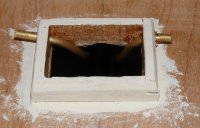
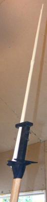
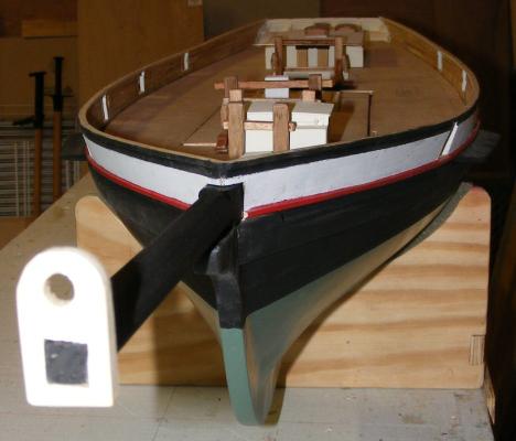
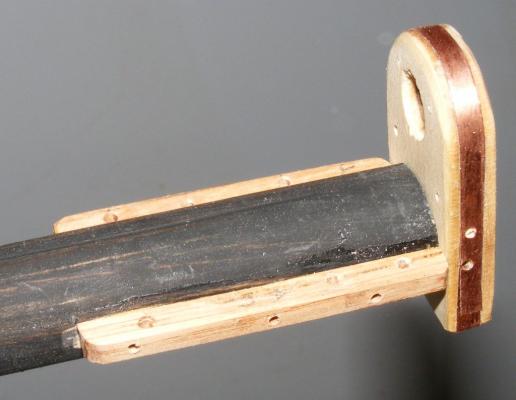
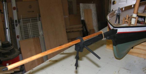
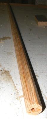
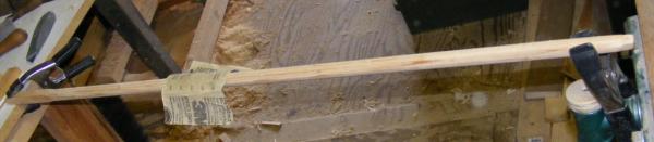
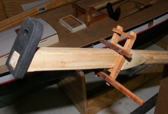
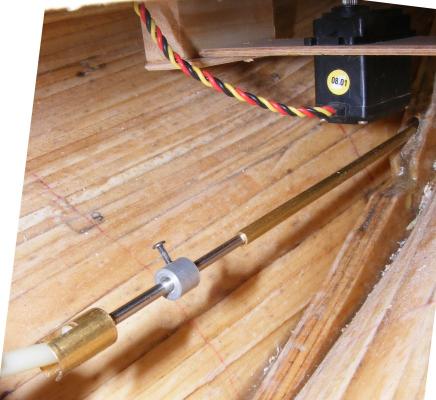
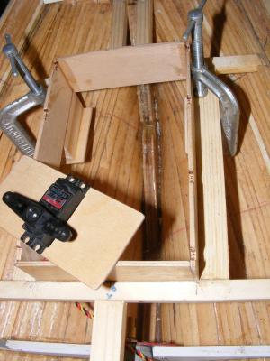
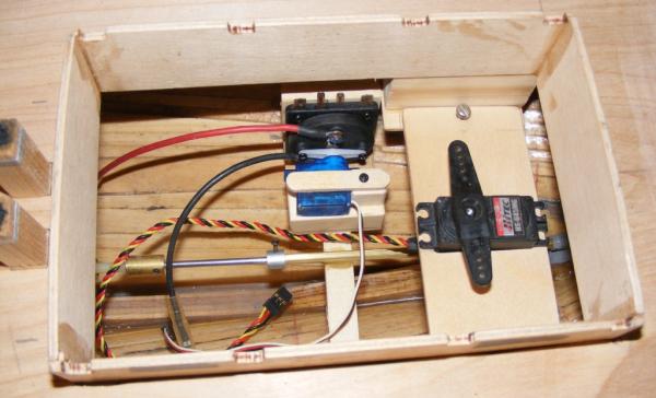
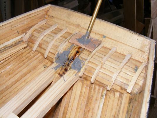
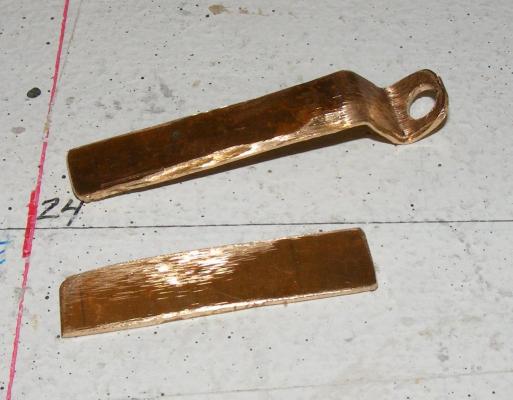
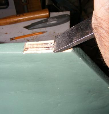
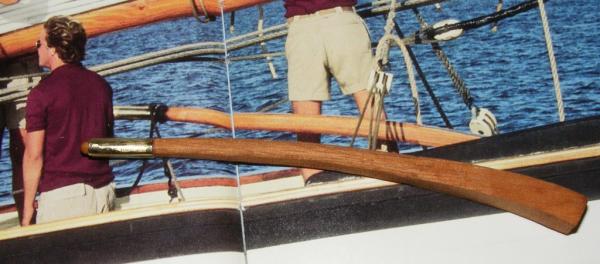
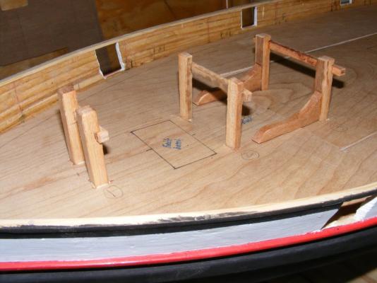
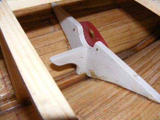
As shown above, there's no space in the counter to install linkages for steering the model remotely that wouldn't be glaringly noticeable and intrusive, so, another way to steer the model had to be devised. The real boat was steered by a tiller. Some 8 feet long and a foot square at it's largest, tapering down to about 6" diameter, and standing about as high as your hip. Under way, you could feel everything the boat was doing which made steering Pride often feel like sailing a yacht. But, if that tiller wanted to go somewhere, it was going no matter who had hold of it. It either pulled away from you, or took you along for the ride, usually depositing you in a heap in the waterways. To tame the beast, a block and tackle were hooked into an eye-bolt in the waterway and attached to a pendant on the tiller. Typically, only one relieving tackle was used opposite the weather helm, but on occasion, two were attached. Maneuvering around the harbor, in and out of the dock, etc, no tackle was attached, but the pendants became a permanent fixture of tarred line turks-headed onto the tiller. Not having a way to hide hard linkages between servo and rudder, I've opted to steer the boat using lines from the servo to the tiller and rig them so they look like relieving tackles. This isn't unheard of but it will require the tiller to be something more than a varnished bit of wood. Actually, I started with a varnished bit of wood... The real tiller though would be of metal, with the wooden part hiding that fact. A steel collar was sweated to a copper tiller and the rudder post hole drilled out. The collar was attached so the set-screw was angled off in a way it could be reached with an allen wrench. The wooden tiller was epoxied and screwed to the metal tiller. The rudder post rod was cut down so the tiller would be at the right height, and a false rudder head was built up to hide the collar. The steering cable will run, port & starboard, from the tiller to a block in the waterway, over to the lazerette hatch where it will go below and to the rudder servo under the cabin hatch. Two brass tube come through the lazerette hatch coaming to guide the steering cable below. A couple of wood blocks glued to the underside of the sub-deck anchor the tubes in place. The tubing was cut flush with the hatch coaming and is hardly visible. A pair of top masts was made from white pine. I look at a lot of photos, especially in Greg Pease's book, Sailing With Pride, to get their shape and finish correct for 1981 as they changed, and were even replaced, through the boat's life. The fid holes are lined with brass tube epoxied in place.


- 79 replies
-
- 9
-
-
- pride of baltimore
- privateer
- (and 3 more)
-
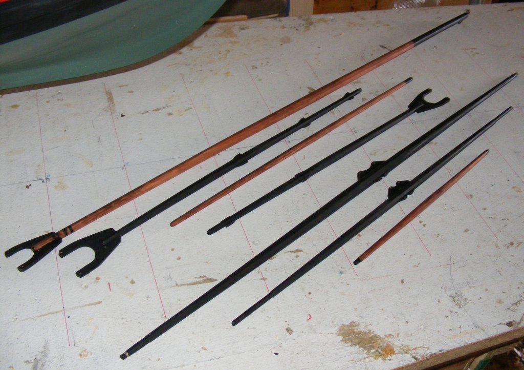
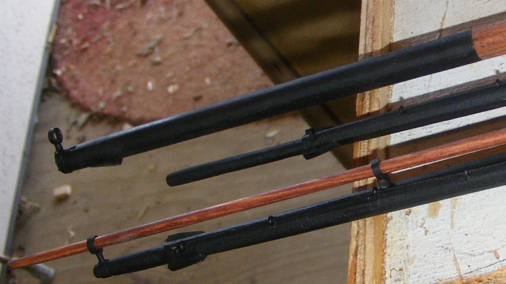
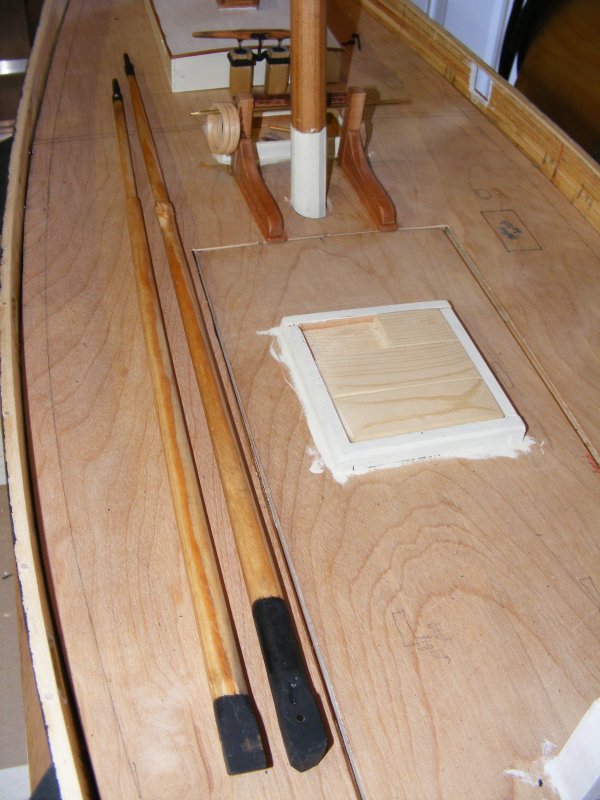
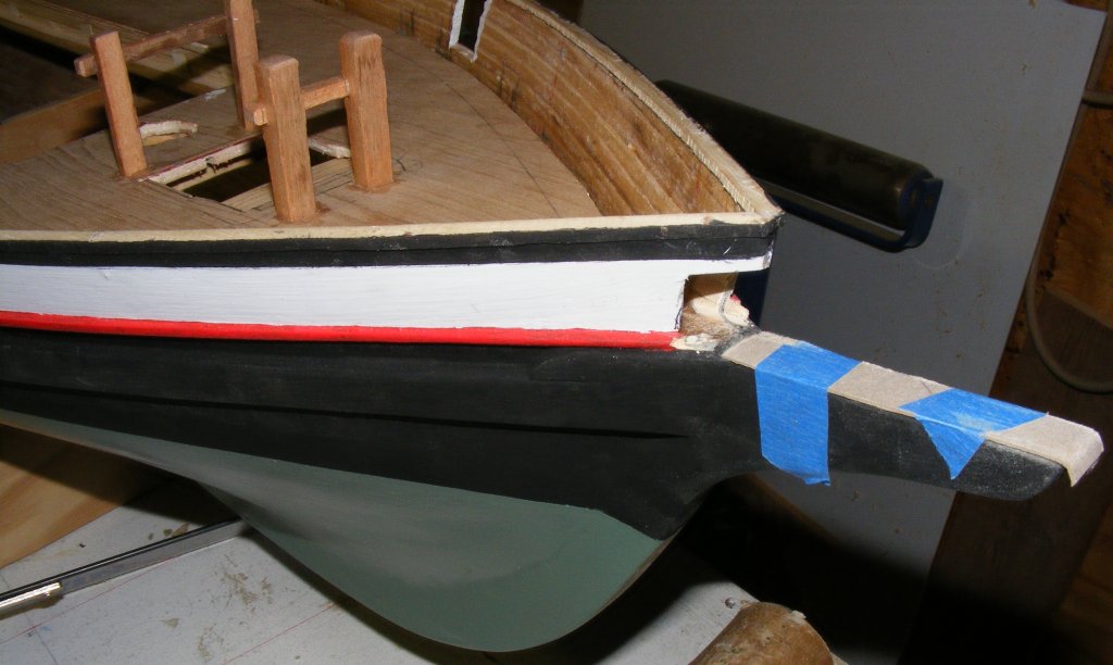
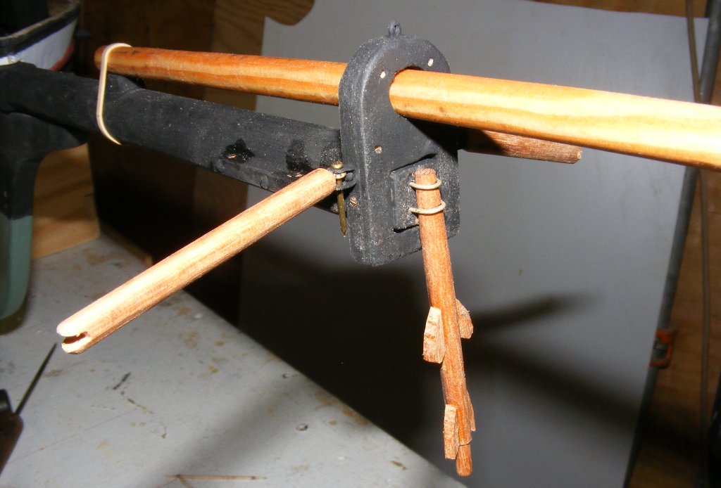
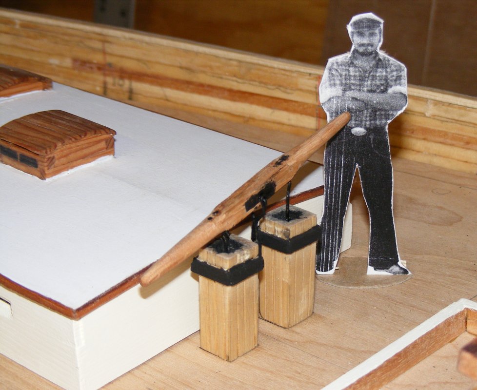
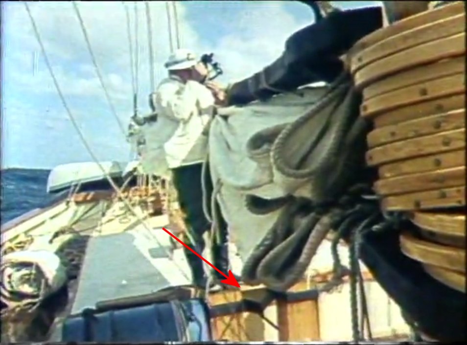
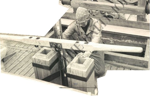
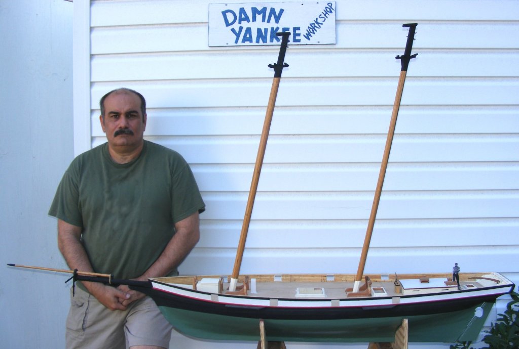
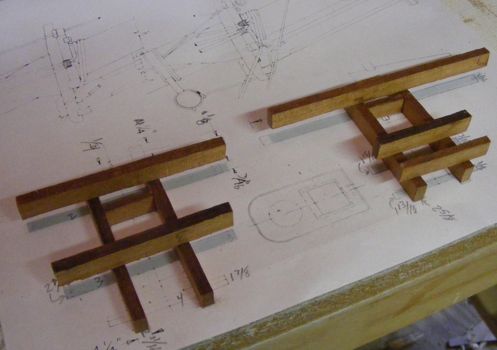
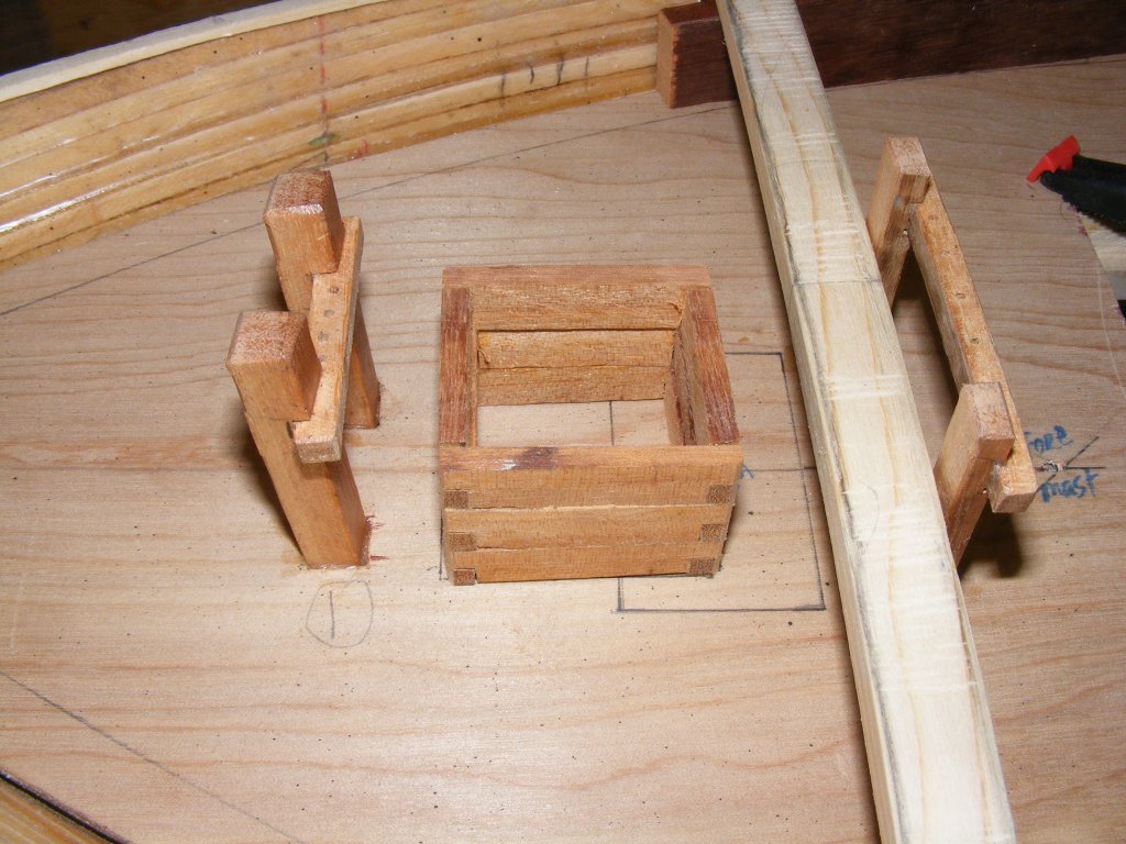
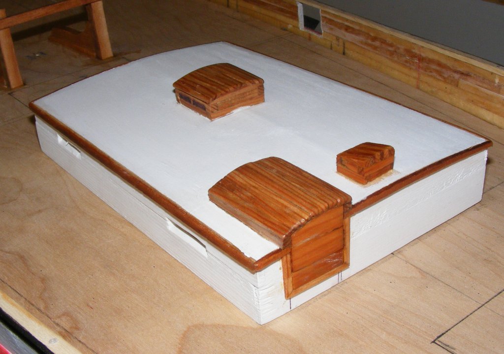
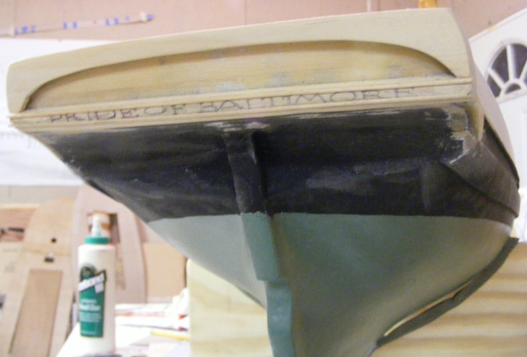
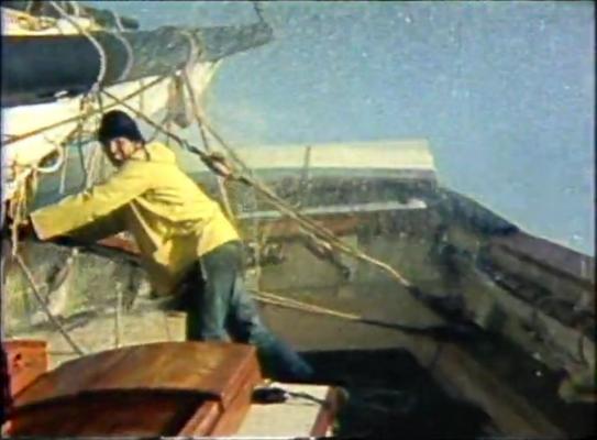
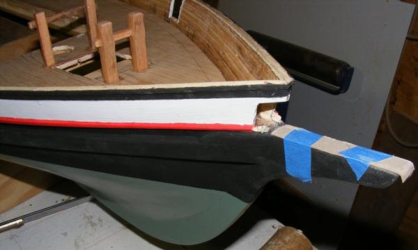
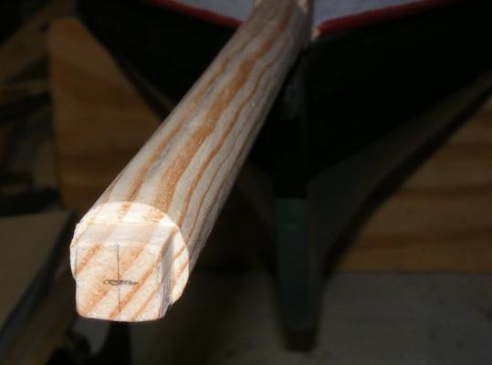
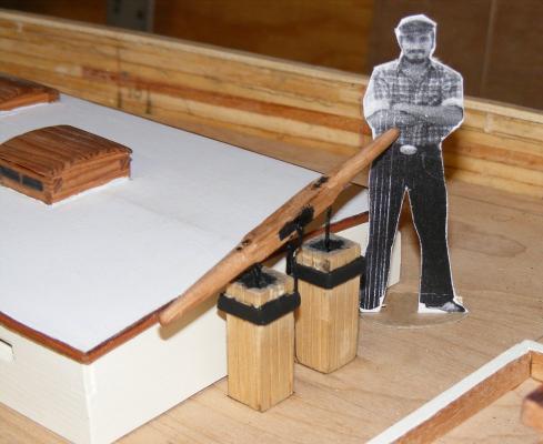
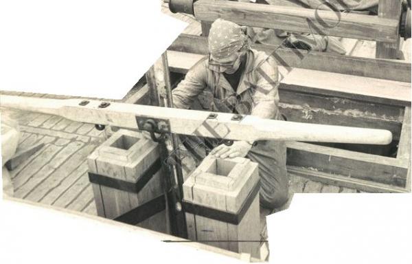
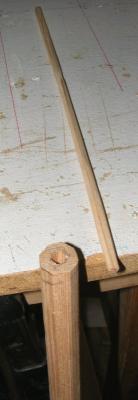
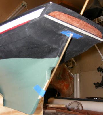
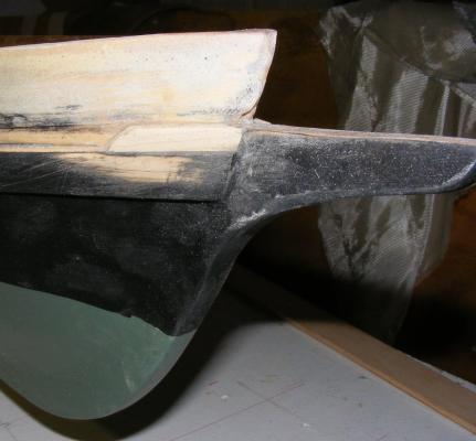
Next up, I started on the bowsprit. It was made from white pine. I wanted the masts as strong and light as I could make them, the bowsprit I wasn't quite as concerned about in that way. The bulwark had to be opened where the bowsprit came through. the bowsprit is square where it passes through the bulwark and it's top tapers as it goes aft almost down to half it's height. The bowsprit doesn't actually sit on the stem-knee, so I taped some card to pad it out and use it to guide the saw at the correct angle. Forward of the bulwark, it's 8-sided, Just forward of the stem knee, it goes from 8-sided to round. The cap was made from the same plywood as the mast caps, strapped with copper tape as was used to do Constellation's bottom. It's glued and pinned with brass rod onto the bowsprit. The bees are red oak, glued and pinned with brass nails, the nails are CAed just before seated. Spreaders and dolphin striker are also oak. The striker is glued and pinned. Brass rod was used for the two U bolts, but they're just for show and aren't structural. The heel block for the jib boom is morticed slightly into the bowsprit. The jib-boom is made from the same white pine. Started off square, was tapered, 8-sided, roughly 16-sided, then shave generally round, and finally sanded, stained and painted While working on the bowsprit, I actually got around to making the pumps. When I was on board, you could barely see these things, surround by water barrels, and we never used them, so I had no memory of how they were constructed, especially the ironwork the connected the handle to them. I actually found a video of the boat on her maiden voyage that had a glimpse of them I could use, and this is the result. The fellow with the sextant is Melbourne Smith who Baltimore City hired to build Pride. I personally have nothing good to say about the man, so I won't say anything. Turns out this is wrong. The iron V portion between the wooden pump heads is attached to the cabin trunk and not to the pump heads at all. The post the handle pivots on sits on deck. I found this out from a Baltimore Sun Papers photo of Fred, the yard foreman, working on the pumps during her construction. So, with a removable cabin trunk on the model, figuring this out should be interesting, but it looks like the pumps will be attached, all of them, the the cabin trunk and will come off with it when it's removed. So, by the third week of May, 2012, the model was very definitely looking like her namesake, even if I no longer looked like I did then.


- 79 replies
-
- 6
-
-
- pride of baltimore
- privateer
- (and 3 more)
-
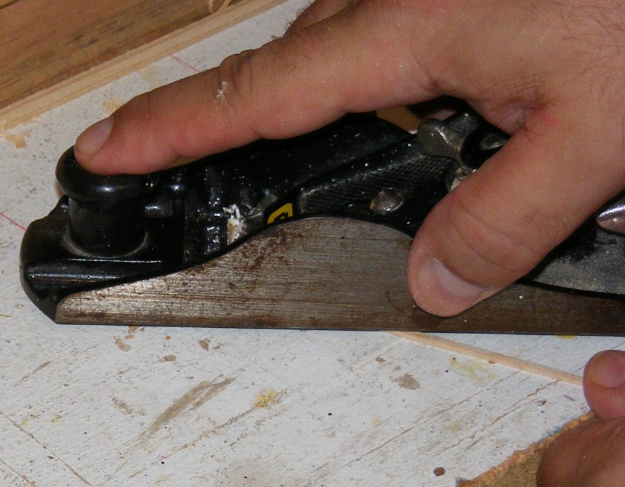
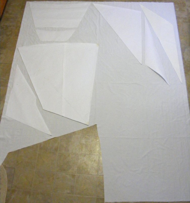
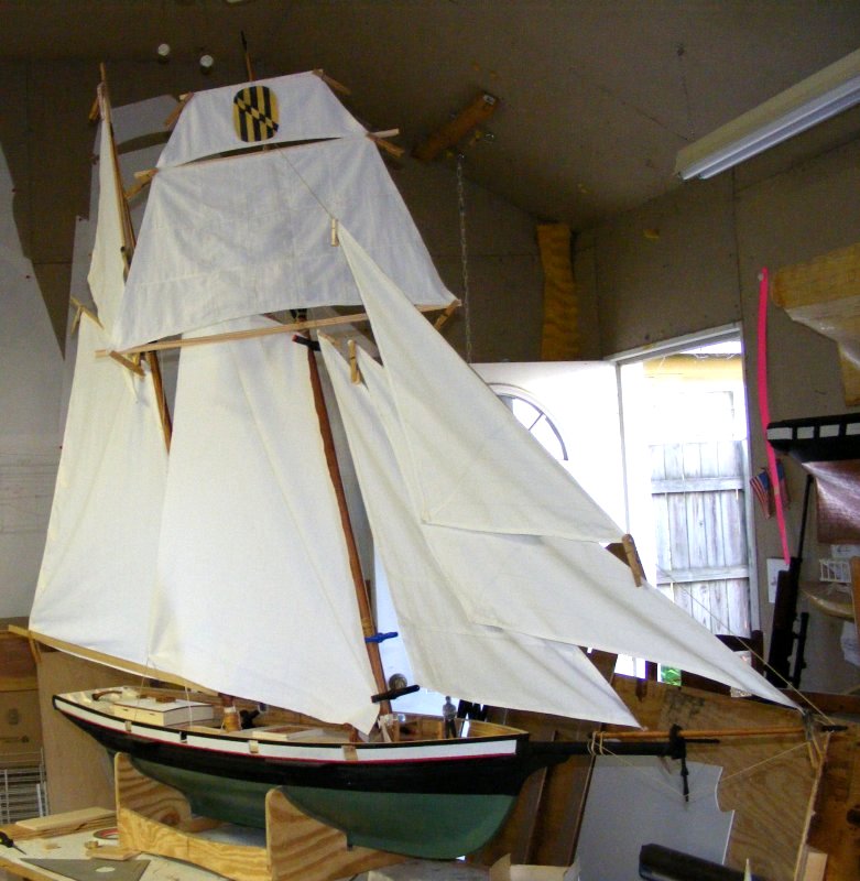
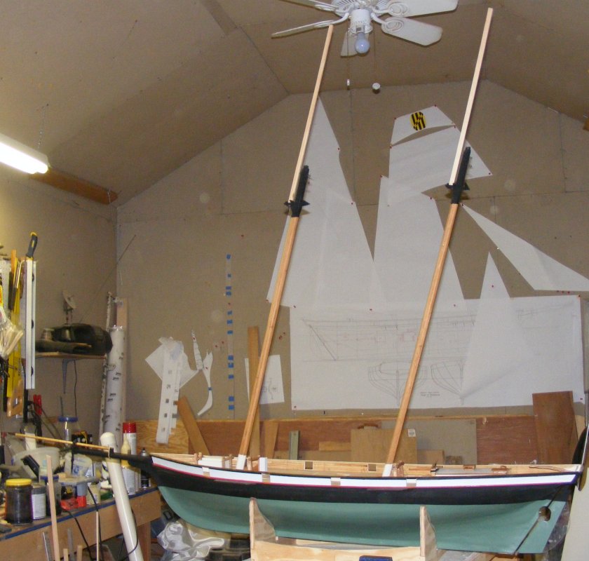
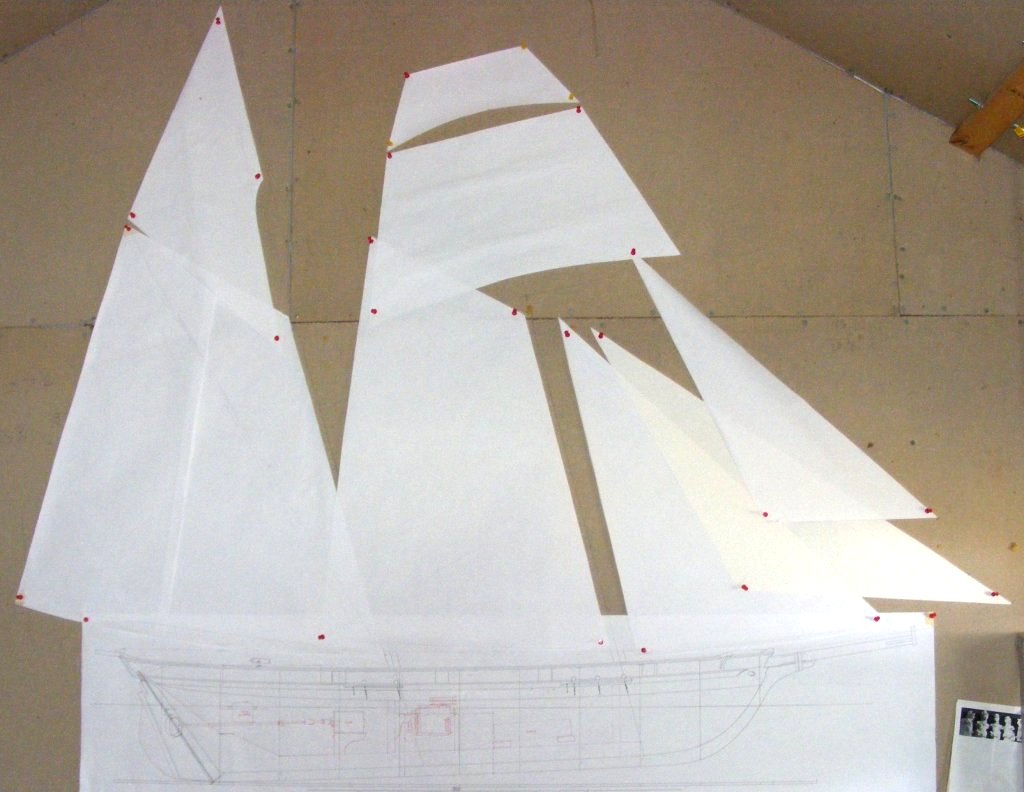
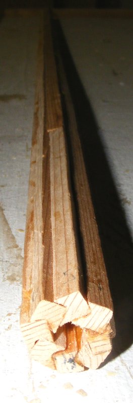
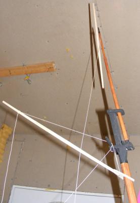
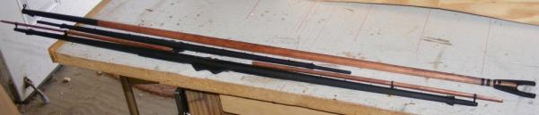
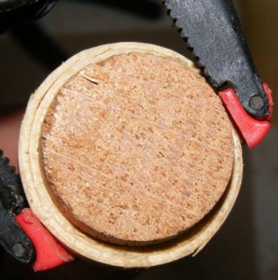
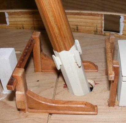
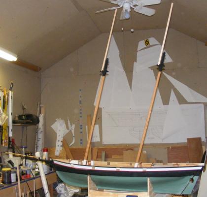
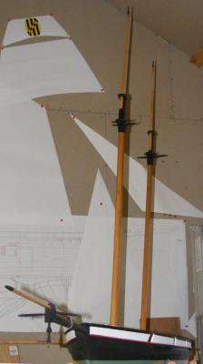
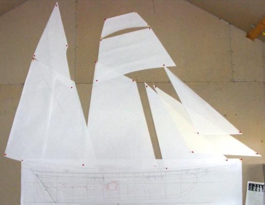
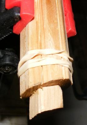
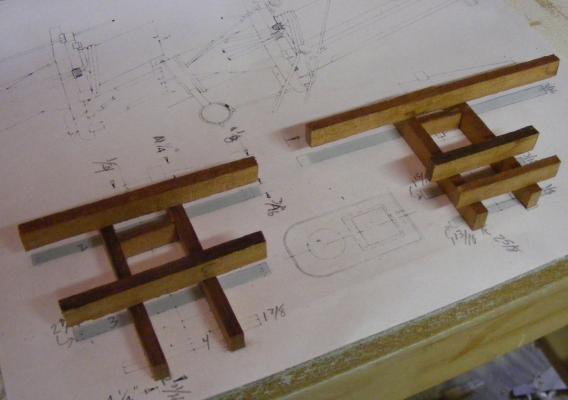
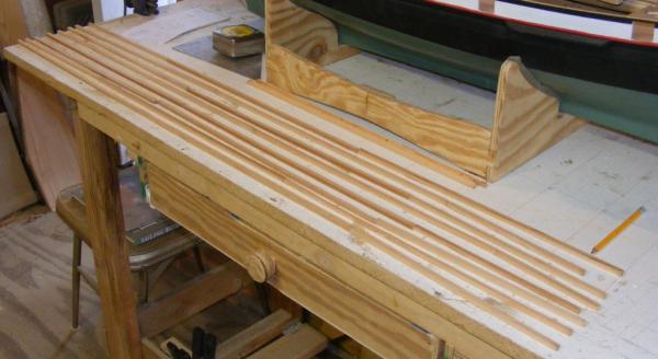
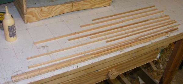
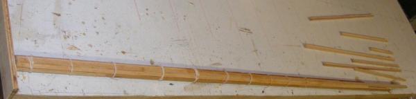
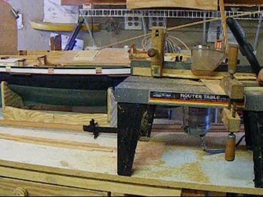
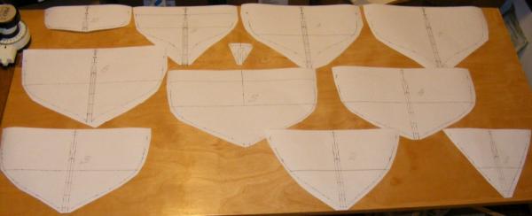
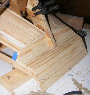
I cut paper patterns for the sails and pinned them up on the shop wall above the profile to see how things would look. It looked pretty darned good to me, Let's make some masts! I made the masts using the "Bird's Mouth" method. There's a lot of math and geometry available on DuckWorks if you're interested in trying this system. My friend Mark, who was building a 12' skiff at my place, made the skiff's 12' mast using this method. Made from 12 foot 2x4's, it turned out a mast that was extremely light, and incredibly strong. In short, Using the formulas for the size mast you want, you cut strips of whatever wood; in my case white cedar scraps left over from making Constellation's masts and spars. The bird's mouth is cut into the correct face. I used a V groove bit in a router set up in a table with finger boards everywhere to hold the work down, and against the fence. It took a little experimentation and playing around, but I eventually got the grove at the right depth. screen shot from the noisy video of cutting grooves in strips. These strips do not need to be the length of the mast as you can butt them to get the right length. Just remember to stagger the butts, and not put any beside each other. The strips are then glued together. It's best to lay them out in some order of assembly as you do this. I used Tightbond III liberally, to glue things up. Take strips from your layout starting at one end of the mast and work toward the other end. Use rubber bands to hold things together as you go. You have to work fast because once it's all together you need to make sure it's straight, and you may need to adjust it, which you can't do once the glue sets. Once the mast is made up, check it for alignment, fix it, and let it set up. The spar is made 8 sided by planing off the corners. I then made an 8 sided dowel of pine to slide inside the mast at either end. The bottom one extends about 2" above where the boom jaws will sit, and extends out of the bottom for the step tenon. The top one about 2" below where the gaff jaws will land and extends out of the top about 1/2" for the cap tenon. These pieces primarily stiffen the spar from the step to above the deck, and at the doublings. The mast is shaved to 16 sides, then a rough 32, and sanded, a lot, to get it round where it's supposed to be. I made cross-trees and trestle-trees from the wood I used for the bitts and every joint is pinned with brass rod CAed in place. The mast head at the doublings was squared and hounds glued and pinned with brass rod. The mast caps were cut from 3/8" plywood. I figure there's going to be a lot of stress on this area when she's sailing, so made it as strong and light as I could. Pride's mast head furniture was all painted flat black, so, so is the model's. The rest of the mast was stained and then given a coat of matte clear. The bottom of the masts were painted a cream color, which I hadn't gotten yet.


- 79 replies
-
- 6
-
-
- pride of baltimore
- privateer
- (and 3 more)
-
U.S.S. Connie - Halyards and general block question
JerryTodd replied to BCG's topic in Plastic model kits
On any model, it's often best to pre-rig yards and sails, and bend sails to yards, before the yards go on the mast. The less you have to fiddle with with the yards attached, the less your chance of breaking something and forcefully relocating the model to another part of the shop. On that note: A friend has a dart board in his shop and keeps the darts at the bench. When something gets frustrating, he flings a dart at the board, instead of something valuable. If you try this, do not put the board near the entry to the shop area, they don't allow modeling tools in jail cells. -
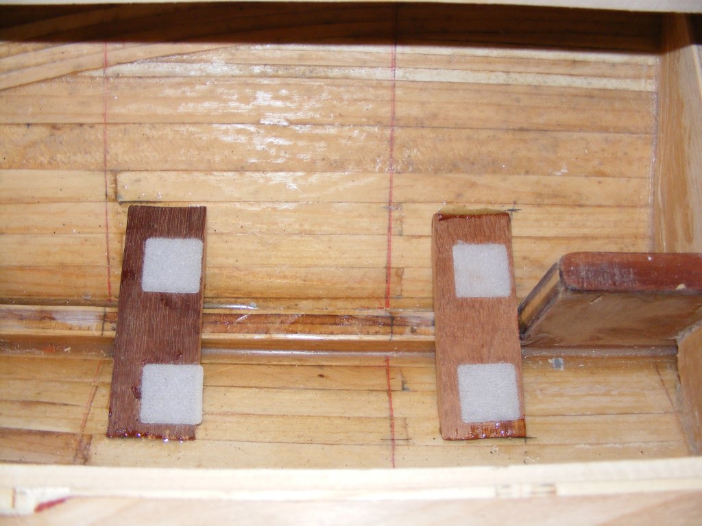
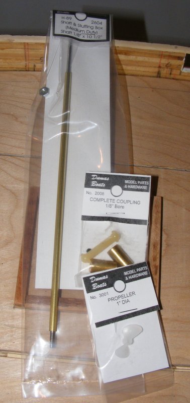
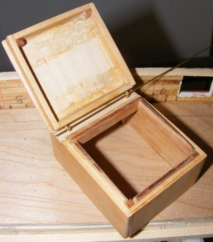
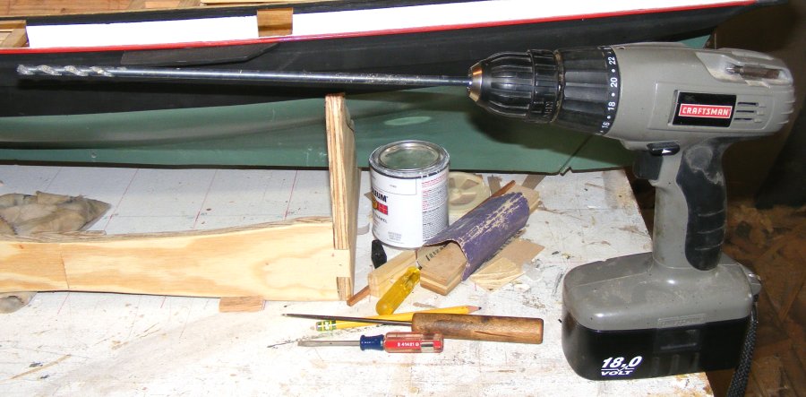
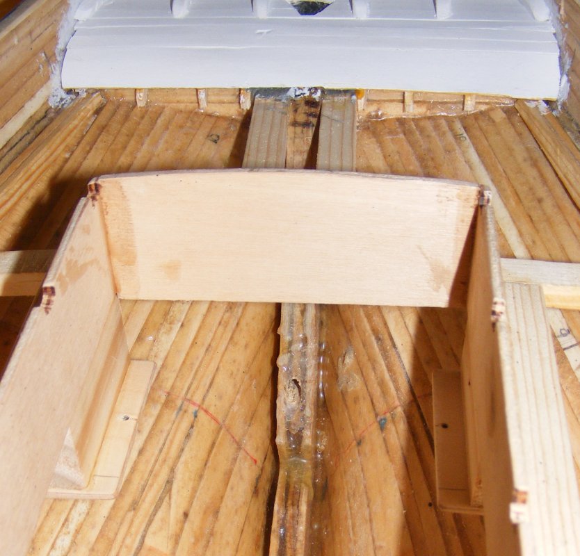
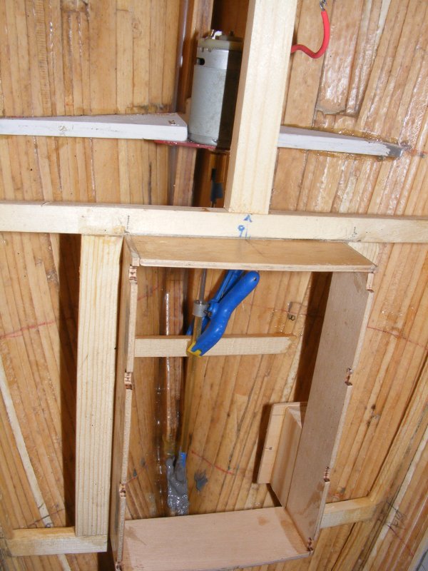
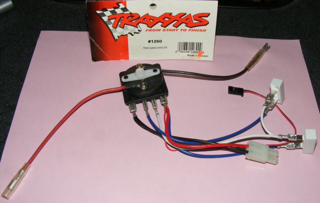
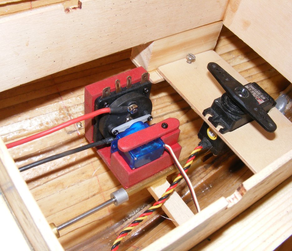
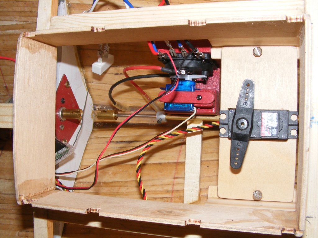
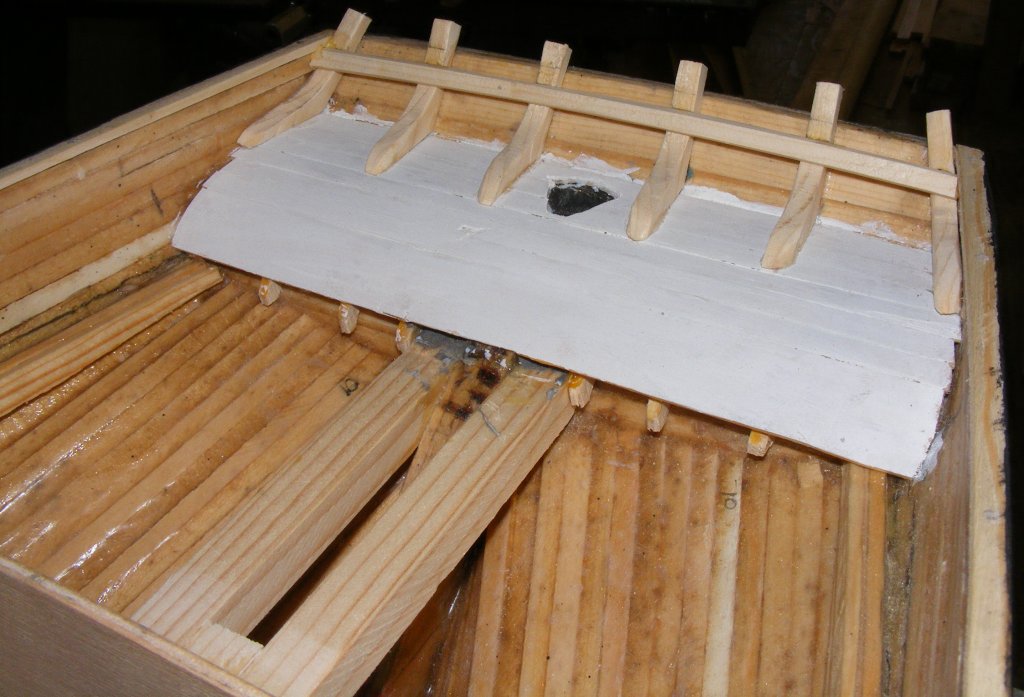
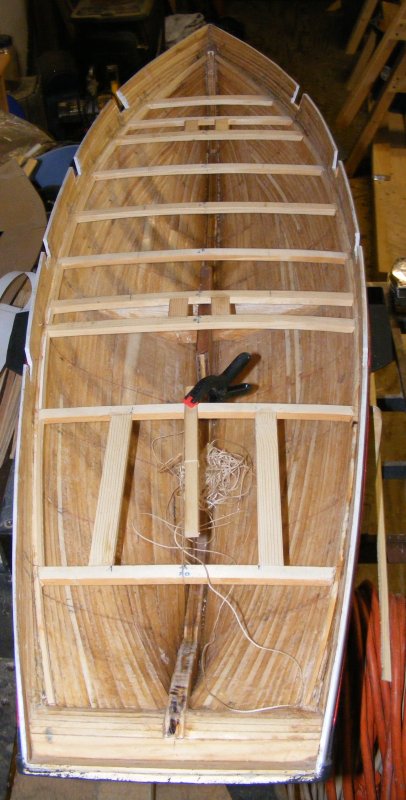
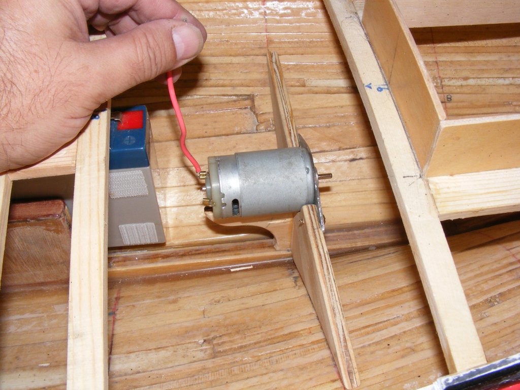
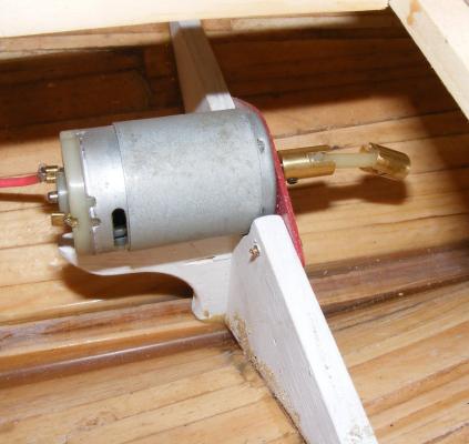
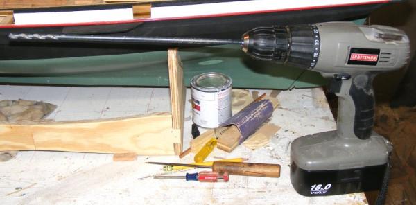
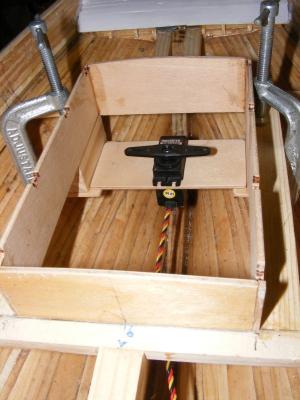
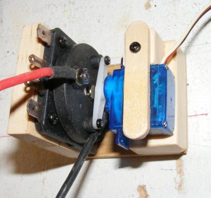
A set of beams was installed forward of the fin trunk, to hold the battery. It will lie flat, as low as possible, and be held by Velcro tabs. The focs'le hatch on the real boat was different than the plans, it was much taller with a hinged lid. I used the same wood used in the other hatch coamings and built it up in three layers, log cabin style. I had some notion of putting something up here, like an on/off switch, but I doubt that'll happen. None-the-less, I made a hinged lid and a hole in the subdeck. In side the cabin hatch, I put in brackets to carry an aircraft plywood shelf for the rudder servo to mount in. It's held by screws and will be removable for servicing. The parts for the prop shaft and motor couplings came in Which meant drilling a hole in the stern post for it. This was done with a long 3/16" bit, over sized so the brass tube "stuffing box" can be adjusted and surrounded by epoxy. This is yet another thing that ought to have been done to the keel while it could lie flat, before it was placed on the forms. JB Weld was added inside to ooze into any nooks and crannies the epoxy missed. Another ordered part arrived - a rheostat type speed controller, with forward and reverse. This is operated by a micro servo, so I made up a mount to handle it. It was fitted inside the cabin hatch on a beam that also serves as a stuffing box support, painted with that red spray paint, and fixed in place.


- 79 replies
-
- 8
-
-
- pride of baltimore
- privateer
- (and 3 more)
-
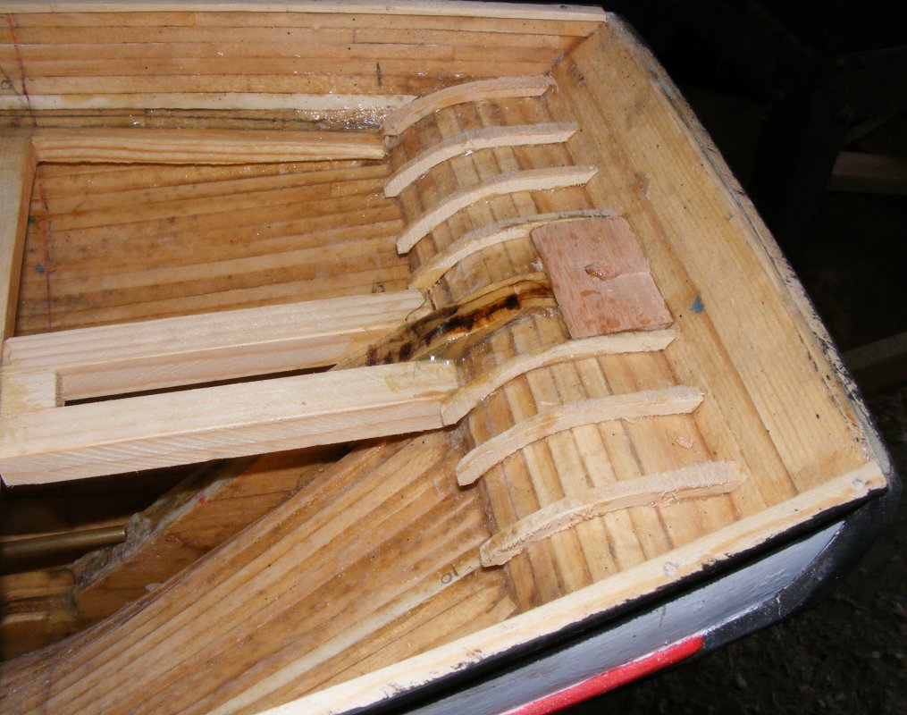
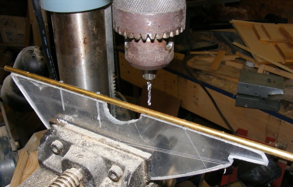
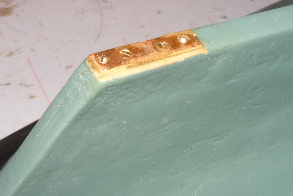
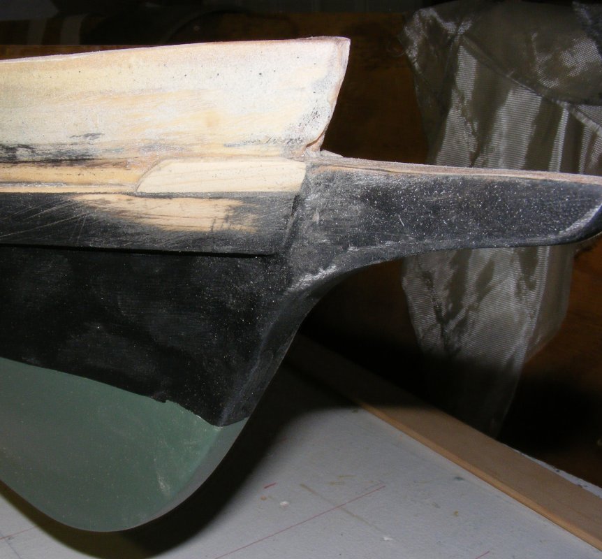
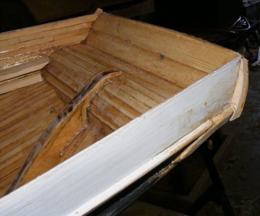
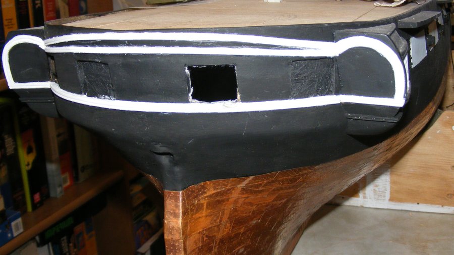
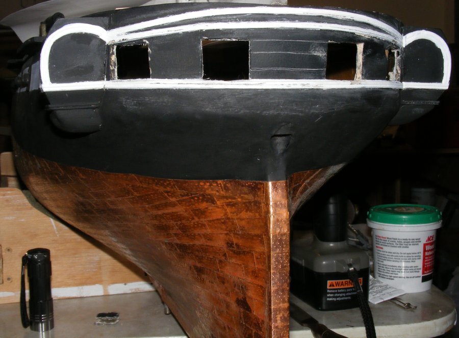
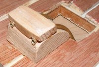
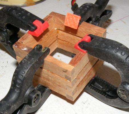
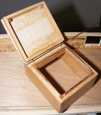
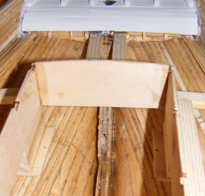
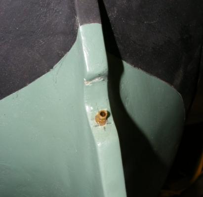
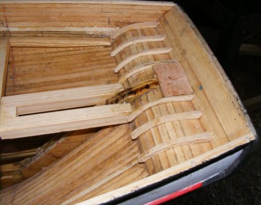
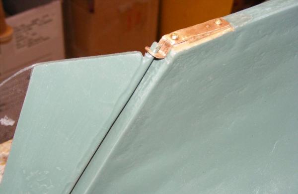
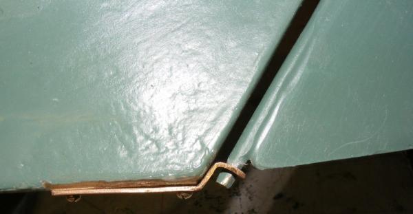
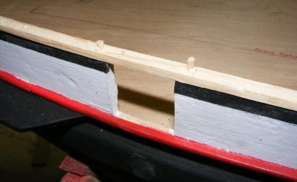
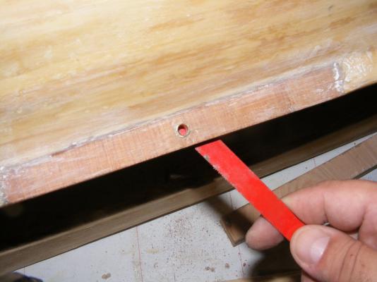
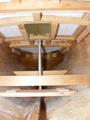
The counter frames went in, showing why I had to trim down the stern post a while back. An oak block was glued in where the rudder tube would go in, to strengthen this area, and a slightly over sized hole drilled through it and the counter. A brass tube was epoxied in with JB Weld. A brass rrod taped to the sternpost behind a spacer made sure everything set up in proper alignment. The rudder was cut from polycarbonate (Plexiglas) and given a brass rod rudder post that was glued and drifted to it with smaller brass rods. A copper plate was cut to size with 4 holes; two for mounting, and two that are tapped for mounting the gudgeon plate. This plate was inset into the boats heel, epoxied and screwed in place. This way water can't seep into the plywood keel because every hole in the hull is lined with epoxy. The gudgeon plate is attached with brass machine screws and is removable. The rudder post slide up through the rudder tube at the counter. The tiller collar will hold it from falling out, the tube keeps it from sliding further up. The gudgeon plate holds the heel of the rudder to the hull and serves as the lower hinge point against the forces the rudder will encounter. Removing the rudder entails removing the gudgeon plate and the tiller, then the rudder drops right out. The visible area around the rudder hole was painted black and the counter planked up with bass sheet. All the wood framing here was painted in epoxy, and each plank was painted with epoxy onit's under side to make sure moisture inside here wouldn't get into the wood. Later this was primed and transom knees were installed. Using bass sheet again, I built the cabin trunk, the visible part that is in essence, a lid. It's details, molding, skylight, compass box, hatch, etc; were all made from the wood of the Pride's top mast I was given earlier. Looking at one of my pictures where the cabin can be seen, I think this wood worked out fairly well for this application. It wasn't strong enough for anything else, like the tiller. I used that "might-be-mahogany" wood used on the bits to make the hatch coamings. I also used it to make the tiller. You may have noticed there is no space to speak of inside the counter where I could hide control linkages for the steering. Instead I'll actually be using the tiller to steer the model, so it will have to have some strength.


- 79 replies
-
- 5
-
-
- pride of baltimore
- privateer
- (and 3 more)
-
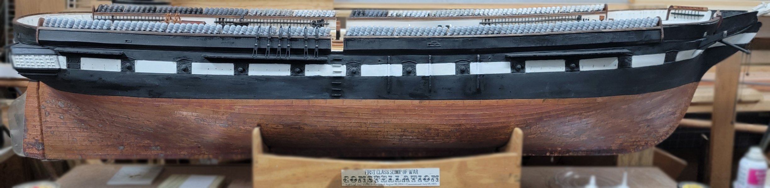
I'm a bit late chiming in here, but I have a great deal of data on the sloop of war Constellation, and if someone is of a mind to turn this kit into something of value, I would be happy to share my data with them. I can't speak to the idiosyncrasies of this kit, as mine is a scratch build, but if you're going this route, it's only a kit up to the gunports and it's scratch from there up. Constellation 1871
-
You plank it up, then cut the ports, thusly:
-
It's your boat.
-
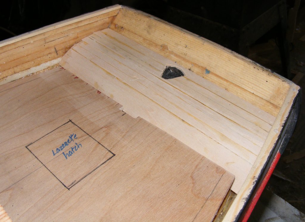
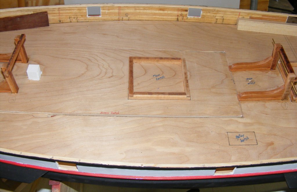
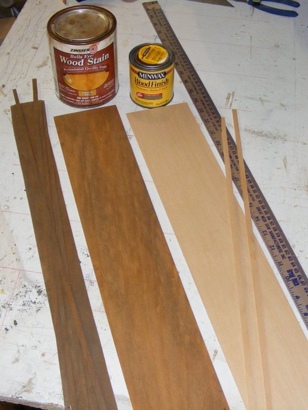
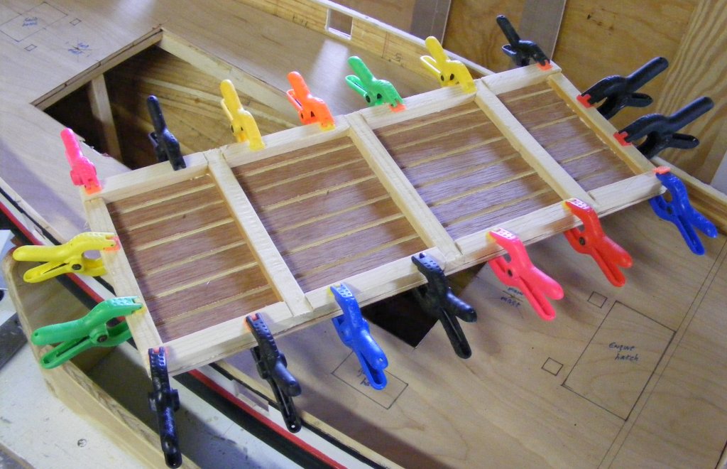
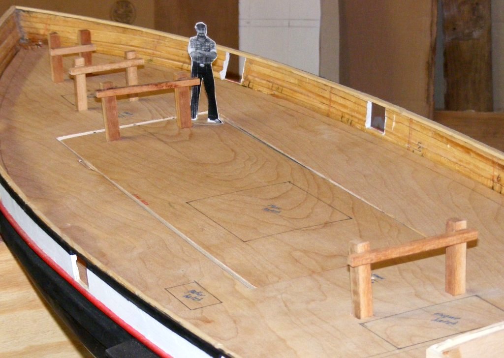
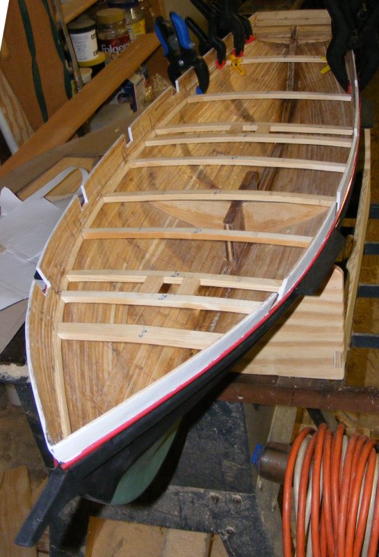
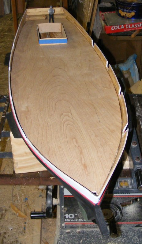
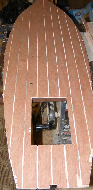
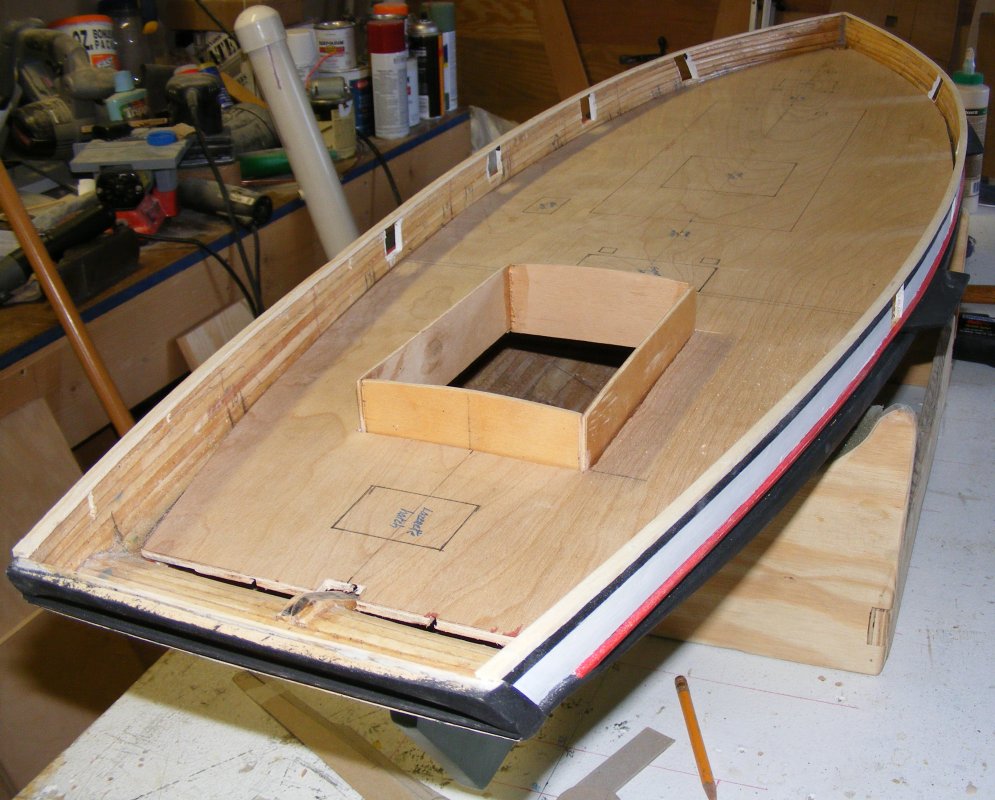
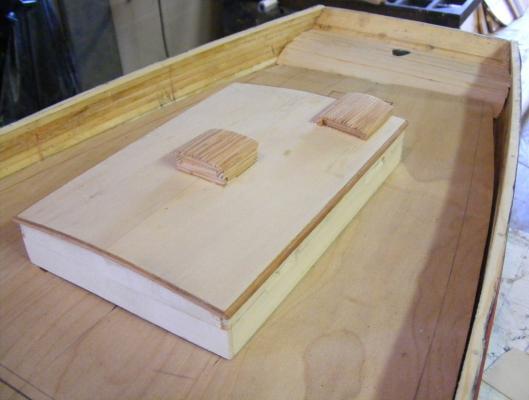
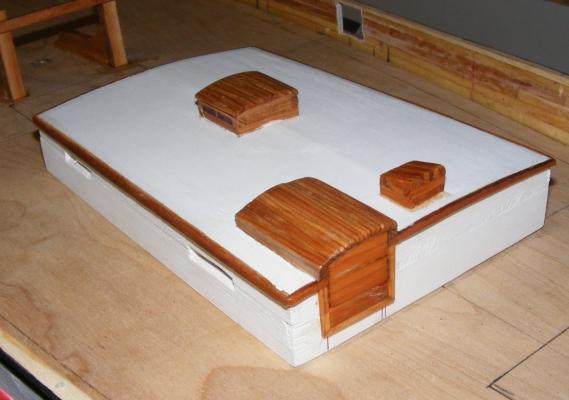
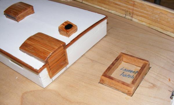
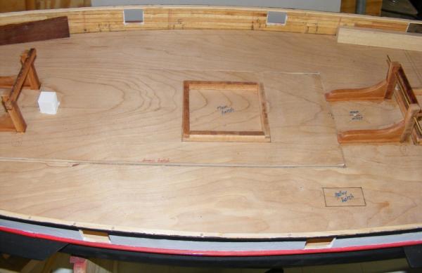
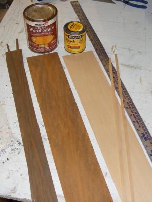
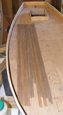
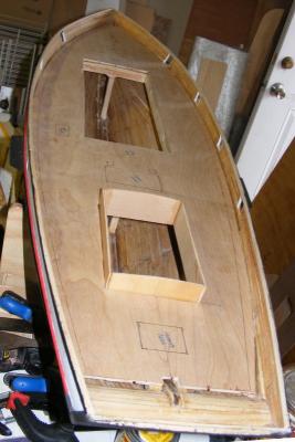
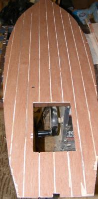
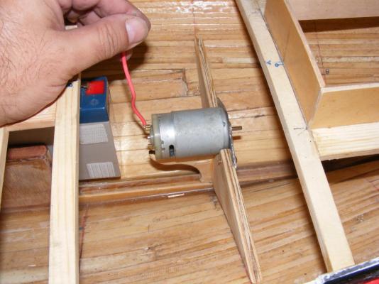
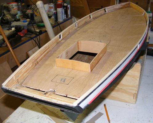
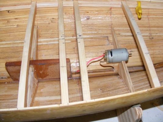
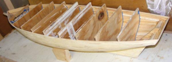
The subdeck's underside will get painted with epoxy which will seal it as well as glue it to the deck beams. A layer of 1/32" bass strips about 1/4" wide will serve as the deck planking. It will be died a combination of stains to approximate the color of Prides original decking. These will be set in slow-cure epoxy when the time comes. All that's a ways off yet, as there's still things to be done in the hull before the deck can go on... For instance, the access hatch has to be framed and cut out. A pair of posts were put in near the mast partners between the deck beams and the keel - these are compression posts and should help prevent deformation of the deck, just in case. The motor mount frame was painted and the mounting plate was painted with the red spray paint from earlier. It was then epoxied into the hull. I was volunteering at the Naval Academy Museum model shop and once night one of the other fellas brought in a handful of splinters. Seems the Pride had her fore-top-mast replaced at Richardson's Yard in Maryland and these pieces came from the old spar. That means they were on the boat when I was. Now to figure out how to incorporate them into the model. The bitts were made from some dunnage found on a dock that looks like it may be some sort of mahogany. It's hard and it matches the color of the originals pretty well. Note the subdeck is marked with locations of deck objects, such as hatches. On the access hatch is the scale main hatchway - which obviouslt wouldn't have been large enough for the model. On the right of the photo is the engine room hatch. The small rectangle on the left of the deck in a box that the galley stack pokes out of. The fellow standing there is me, in 1:20 scale. It's a picture of me from about a year before my time on Pride and serves to show scale in the photos. The hatchway marked in the right photo is the focs'le hatch.


- 79 replies
-
- 5
-
-
- pride of baltimore
- privateer
- (and 3 more)
-
Standing rigging color preference and historical musings
JerryTodd replied to Chuck's topic in Masting, rigging and sails
From the smell of them, I thought the old model's rigging was tarred just like their prototypical counterparts - they always smell like Stockholm tar to me. -
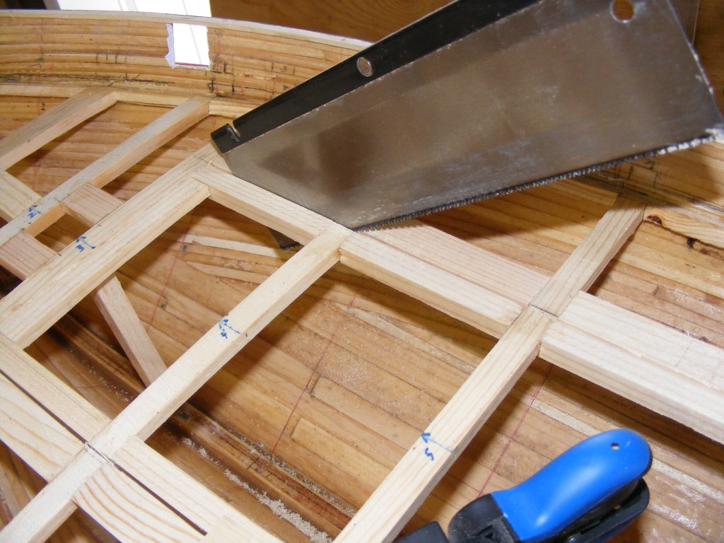
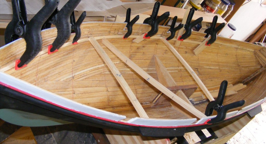
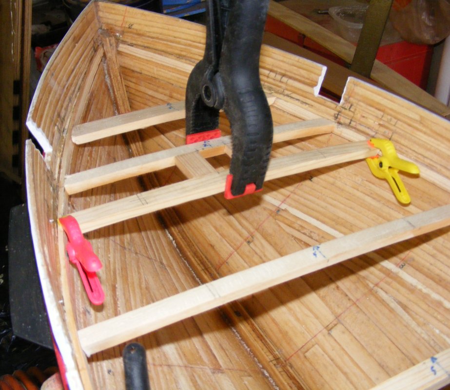
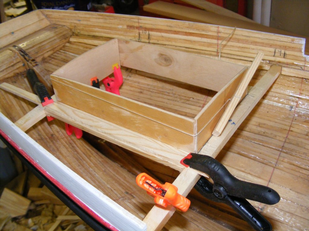
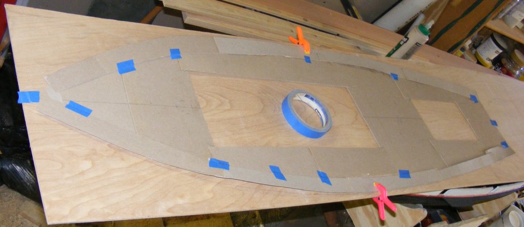
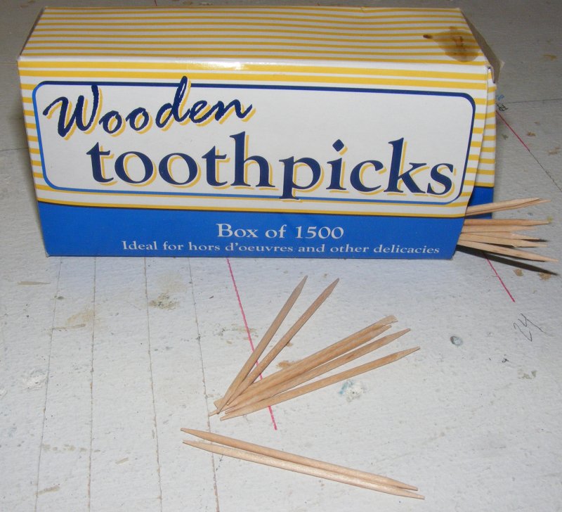
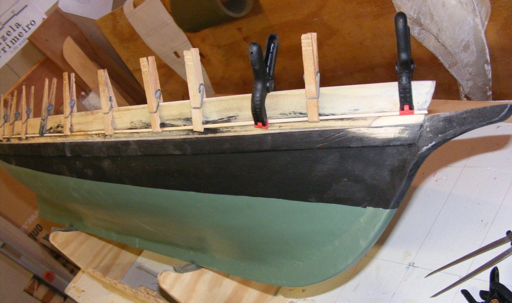
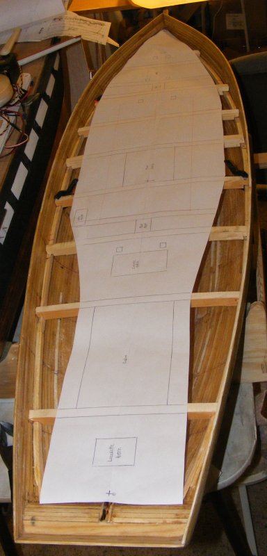
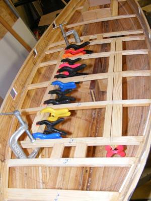
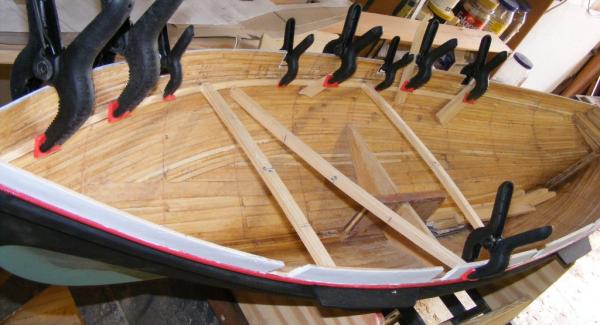
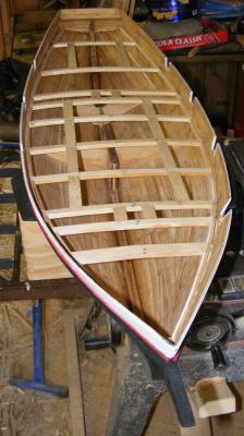
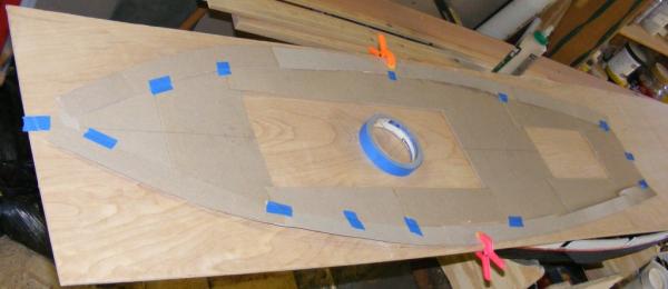
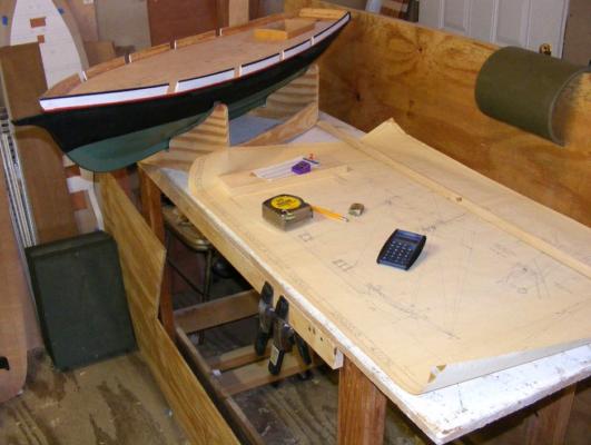
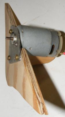
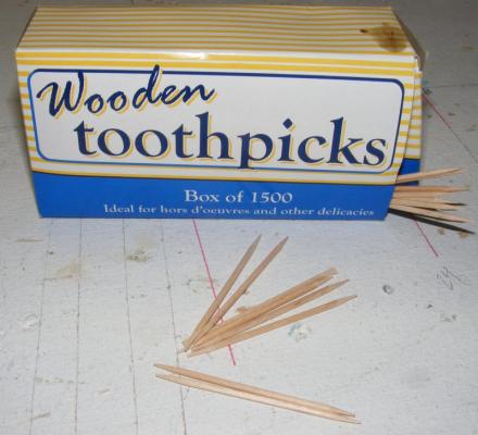
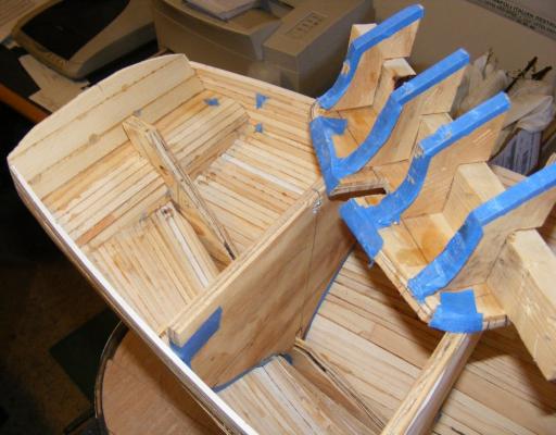
So, once more in go the clamps. This time, making sure I measure from the right point, I used a different approach. I laid in two layers of 1/8" thick strips, then installed the deck beams - now recut thinner - butted to the clamp. Another layer of 1/8" strip was installed between each beam. Mast partners were installed, then framing for the main cabin and the access hatch. The access hatch doesn't correspond to any hatch actually on the boat - none of them was large enough at this scale to give me the access inside I needed. The inner cabin trunk is framed from 1/8" plywood that came from a cigar box, or something like that. This isn't the cabin you'll see, but an inner sleve the outer cabin trunk will slide over, like a box lid. This will help keep out water. Card stock was used to lay out the deck and make a pattern. The sub deck was cut from 3/16" luan plywood. It was kerfed underneath to help it flex in two directions; sheer and camber. After giving the top strake a coat of black, I started marking the spar plan with 1:20 scale dimensions in preparation of making the spars. I made a mounting plate for the motor from an electrical box cover plate. The motor came from an old cordless drill. I was getting concerned that a section of bulwark might get broken off by some big clumsy oaf, like me, so I put a rail on to connect it all. This isn't the finish cap rail, but more of a structural member. This rail will actually be in two parts. This part is the inner part mounted flush with the outboard side of the hull. It's glued and trenailed (wooden toothpicks) into the top of the planking. An outer part will be applied later, bring the rail to it's correct width. And some more paint.


- 79 replies
-
- 6
-
-
- pride of baltimore
- privateer
- (and 3 more)
-
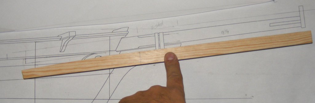
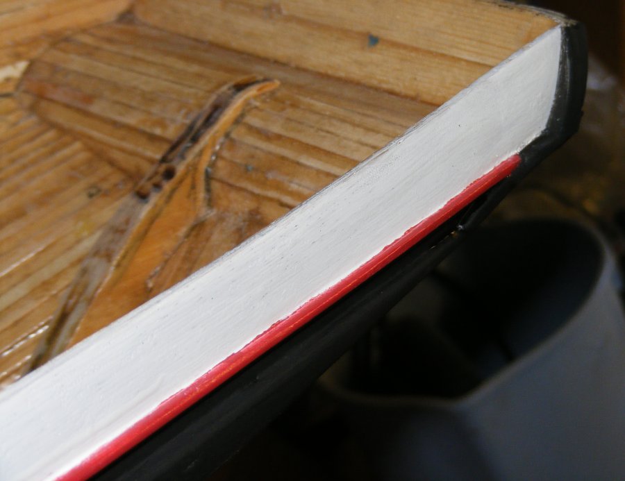
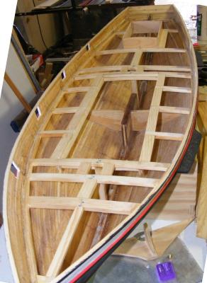
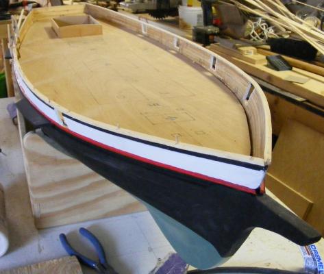
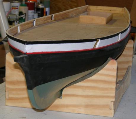
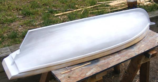
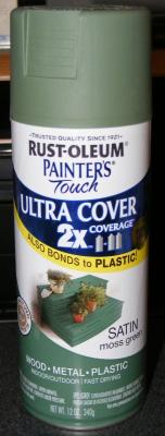
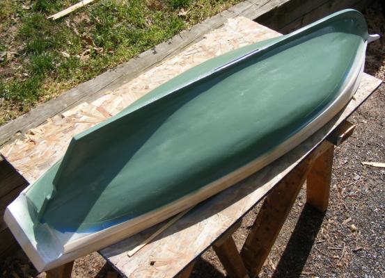
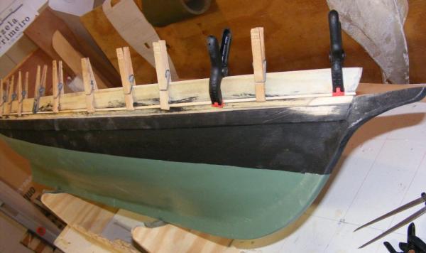
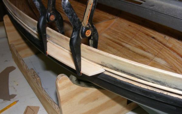
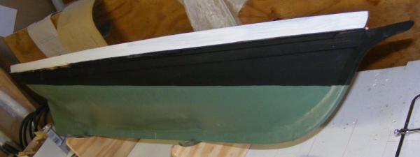
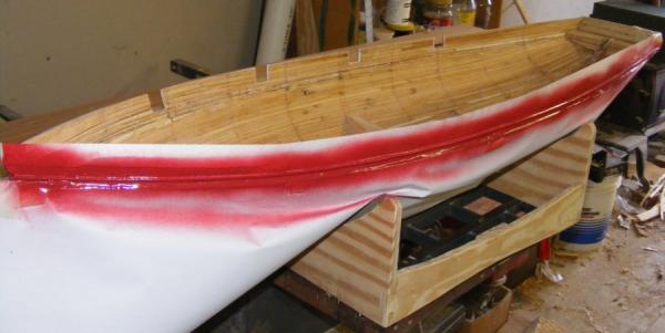
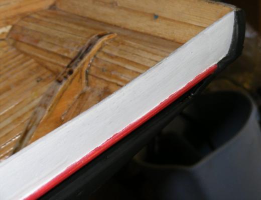
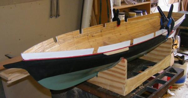
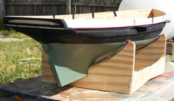
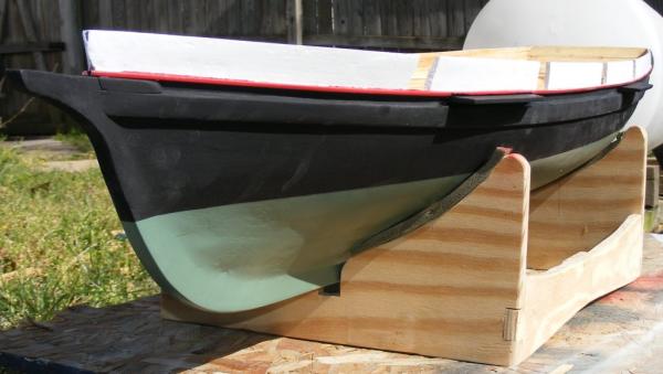
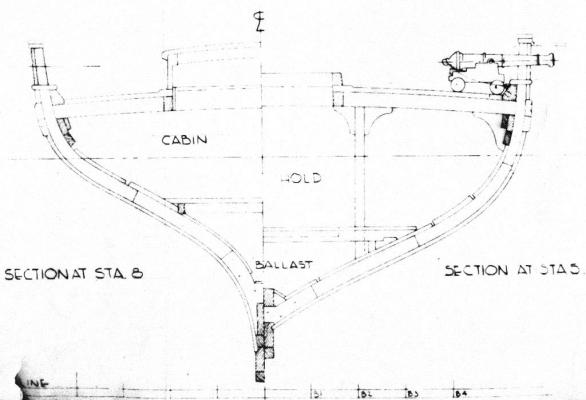
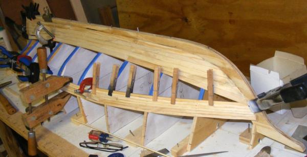
Fortunately when I got the plans from Gilmer, I got the full set with structural details, especially a cross section of the structure; because it's not at all easy to tell where the top of the deck is. This apparently was a problem found by some company doing flooding analysis on her, they were given a profile and not knowing where the deck was, calculated to the top of the rail. As it is, the top of the deck is level with the top of the wale, which was the next piece to be installed. I had a length of screen molding we used as a batten, or spline, when laying out Mark's skiff on the plywood. It was precisely the width of the model's wales. With the wales on, the prop notch cut, and the dagger board trunk installed, hull was ready to get some paint. First, a coat of primer. Then I found some spray paint that pretty closely matched the color of Pride's bottom paint I thought I had a picture of Pride out of the water where the color of her bottom could be seen, but nearly all my shots of her hauled out are black & white newspaper photos. This image is from 1980 and you can see a little of her bottom color. I hand painted some flat black above the waterline. The wale widens forward at the hawse pipes, this was installed next, but I'm not drilling the hawse holes yet. Again, referring to the cross-section, the top of the deck extends to the top of the wale. This is capped with a waterway log, which itself has a cap. There's light planking above this to the cap rail. The portion of the waterway cap that's exposed outboard forms something of a channel down the boat's side, and this part of the cap is painted red. I cut some 1/16" square strips and sanded them 1/2 round. This was applied to the outside of the hull to represent the outboard portion of the waterway cap rail. At the top of this channel between the wale and the waterway cap, snugged up under the cap are the channels. This were more white pine, thicker at the hull and tapered to about half their thickness outboard. One was installed. Looking back, I'm not sure why I only did one, but Some black paint touched up the faux waterway rail and the channel below it. Then put a coat of white on the bulwarks, and cut the gunports. The wing transoms and fashion pieces were fabricated and installed, and the facny piece and moldings on the transom.. Something didn't look right with the deck clamp, and upon investigation, I found it was off at the bow and stern. It was too well attached to just detach and move, so I pulled it out completely. Had I installed the wale first, I could have more accurately gauged where to install the deck clamp (minus the thickness of the plywood sub-deck and decking). Finding a small container of red paint turned out to be a challenge. I wound up with a $2 can of spray paint and proceeded to paint the waterway cap. Finally, the rest of the channels were installed. And everything painted


- 79 replies
-
- 7
-
-
- pride of baltimore
- privateer
- (and 3 more)
-
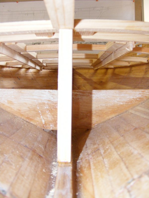
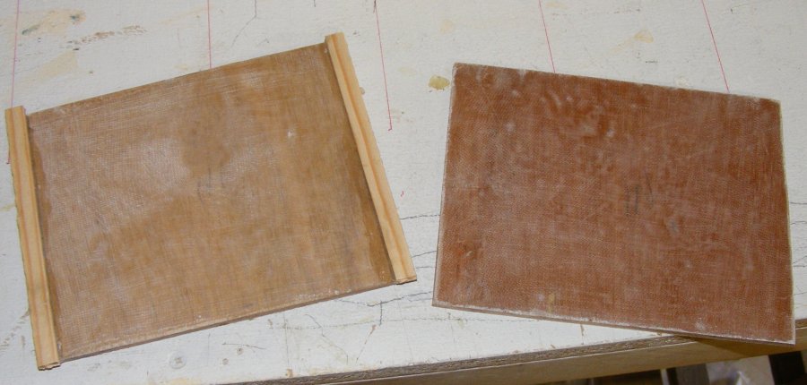
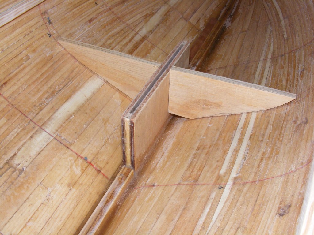
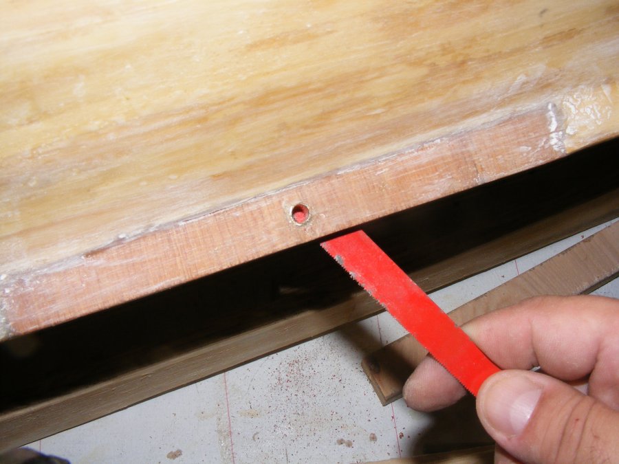
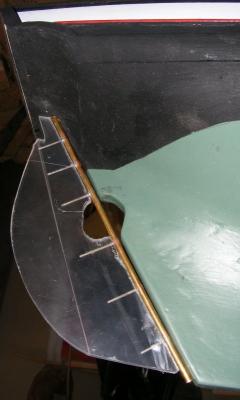
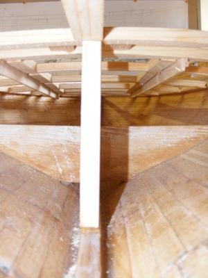
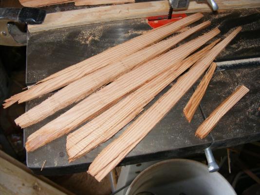
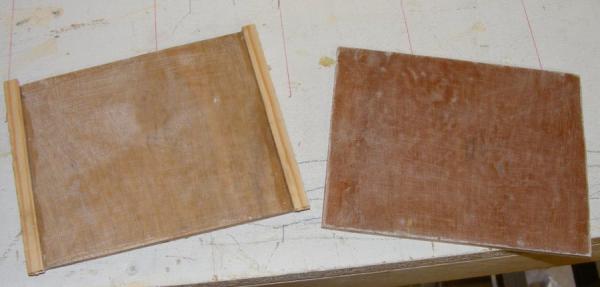
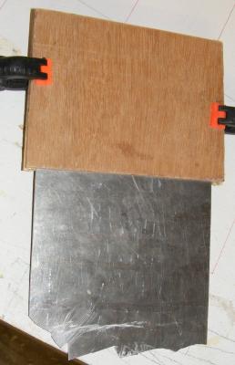
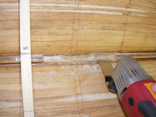
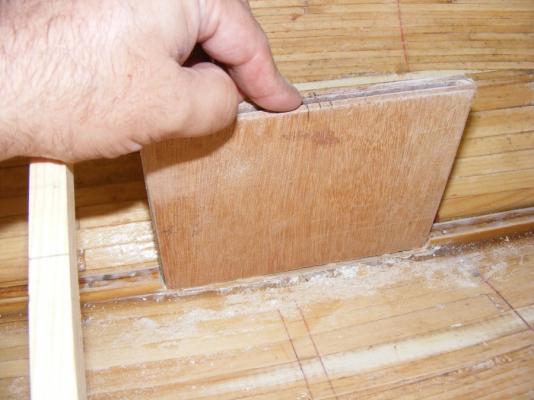
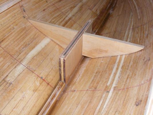
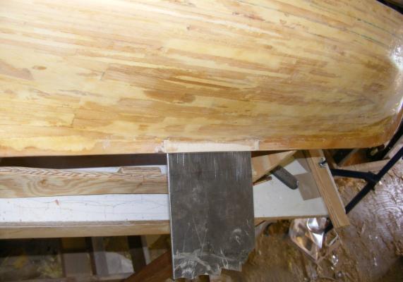
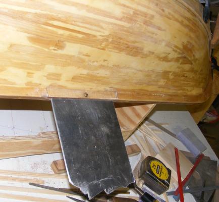
With the hull glassed, I began to install the deck clamps. These were of the same pine used to plank the hull, only 3/8" wide and 1/8" thick. One layer was epoxied to the hull. The placement of the deck beams was determined based on hatch locations, mast partners, etc. While my friend Mark was building his skiff outside the shop, I put some of his leftover epoxy into the bilge of Pride's hull to fill crevasses, seal, and strengthen the garboard area. There are things that should be done to the keel while it's still just a flat piece of wood, and before it's a permanent part of the hull. Cutting the cut-out for the propeller is one such thing. When you don't do it then, you have to do it later and it's a lot harder to not mess it up. I wasn't sure how I was going to attach the external ballast until I saw some Newfie schooner models as big as Pride that used a simple fin with about 15-20 pounds of lead in a bulb. Going with the idea, I started building a dagger-board box for the fin to slip in to. The sides are 3/16 luan plywood, glassed on the inside faces, with a pine separator epoxied on fore and aft. The remaining portion of the aluminum sheet I cut Constellation's yard trusses from will be the fin. This oscillating tool I got from Harbor Freight for $10 made quick work of cutting the hole for the trunk to fit in to. This, of course, is another thing that should be done to the keel before it's part of the hull. Portions of the form at that station became internal braces for the dagger-board trunk. They would be epoxied in. The trunk was itself epoxied in. After sanding, some glass cloth was laid over it to fair it into the hull and the keel. Anything not covered with cloth was painted with resin. The trunk got a cap from a bit of cherry I had around and a motor mount was fashioned from one of the forms. A hole was drilled at the center of the trunk along the keel and a brass tube was epoxied into it. When it set, I cut the tub flush inside and outside. A matching hole was drilled in the fin, where a brass machine screw and nut would hold the fin to the boat. The tube protects and seals the end grain of the trunks plywood where the screw will go through. I began to fit the deck beams, but these seem thicker than they need to be. They're like this on Constellation, but there's a lot more head-room inside Constellation compared to Pride where space is at a premium.


- 79 replies
-
- 4
-
-
- pride of baltimore
- privateer
- (and 3 more)
-
I do need to build a pram to chase them around in.
- 79 replies
-
- 1
-
-
- pride of baltimore
- privateer
- (and 3 more)
-
I don't think I have more than $200 invested in her yet. Her keel was some scrap 3/8" CDX plywood, as were her forms. Her planking was from some left over white pine 1-by-something "shelving board" my step-dad called it. The sails were a couple of yards of Supplex for $10-15. The radio was bought on ebay for about $100 and I have multiple receivers so I can run any one of the three models with the one transmitter. The servos were the expensive part at about $100 for the set of them. There's some glue, polyester resin and glass cloth - but no great quantities, and the single gallon of resin has served three models so far. Paint, but again, not any great quantities. I'm a Scottish Jew, pinching pennies is in my blood.
- 79 replies
-
- 1
-
-
- pride of baltimore
- privateer
- (and 3 more)
-
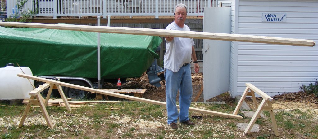
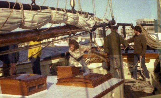
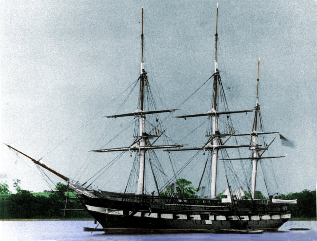
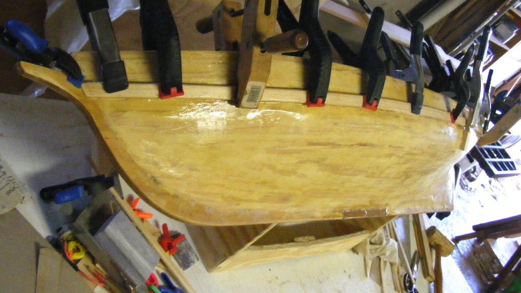
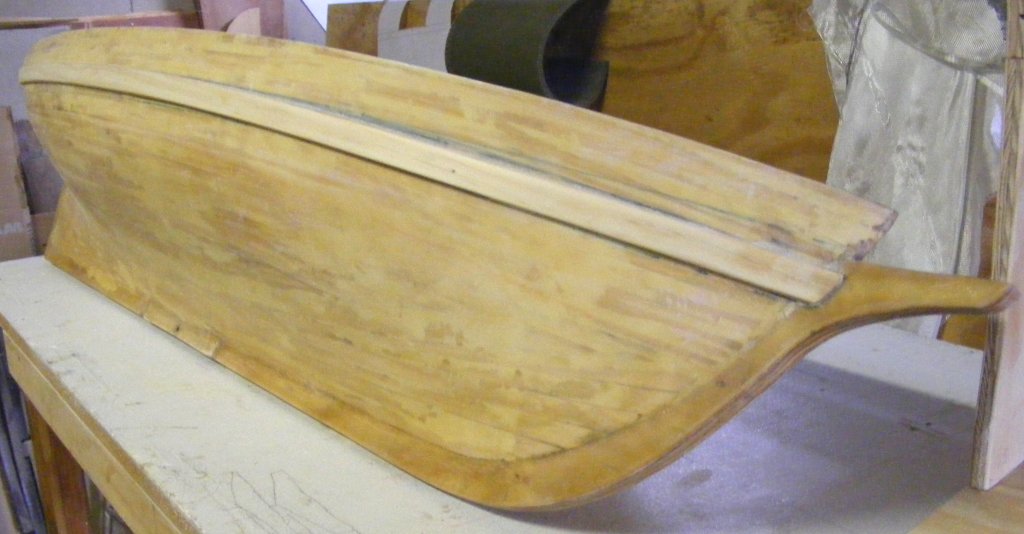
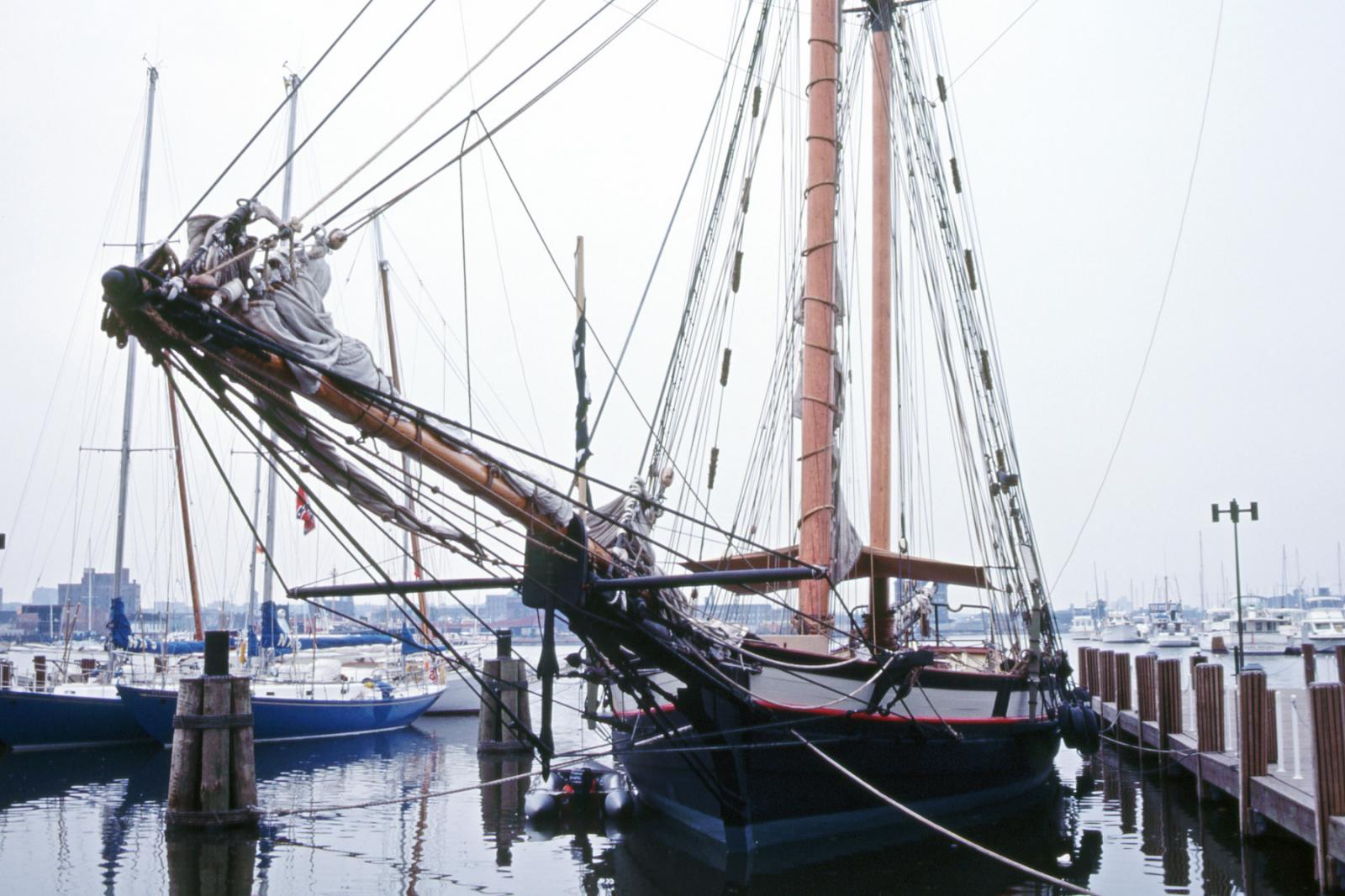
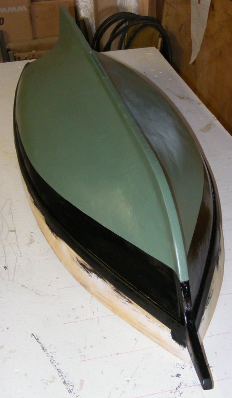
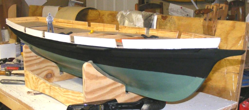
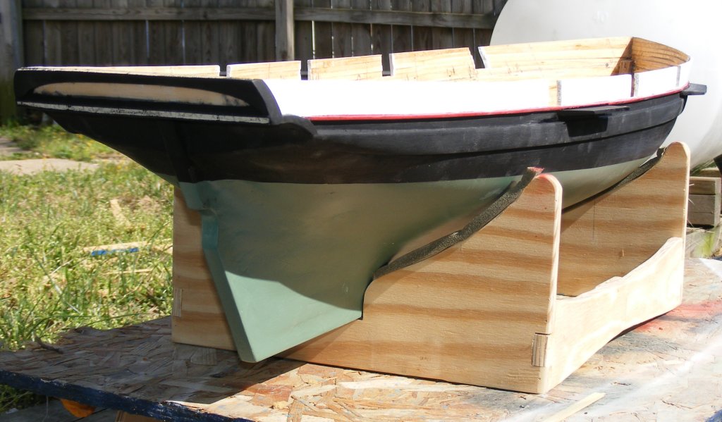
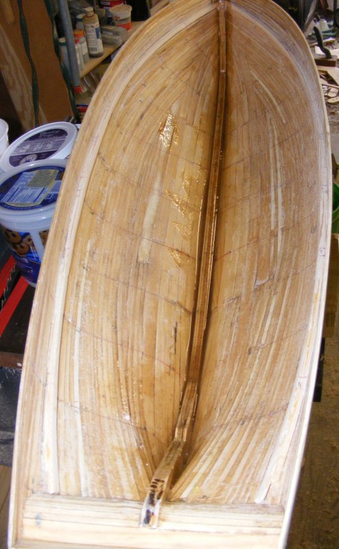
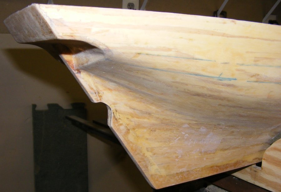
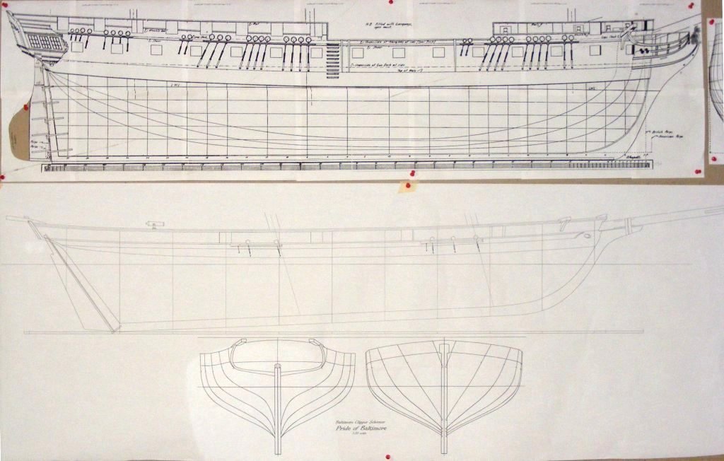
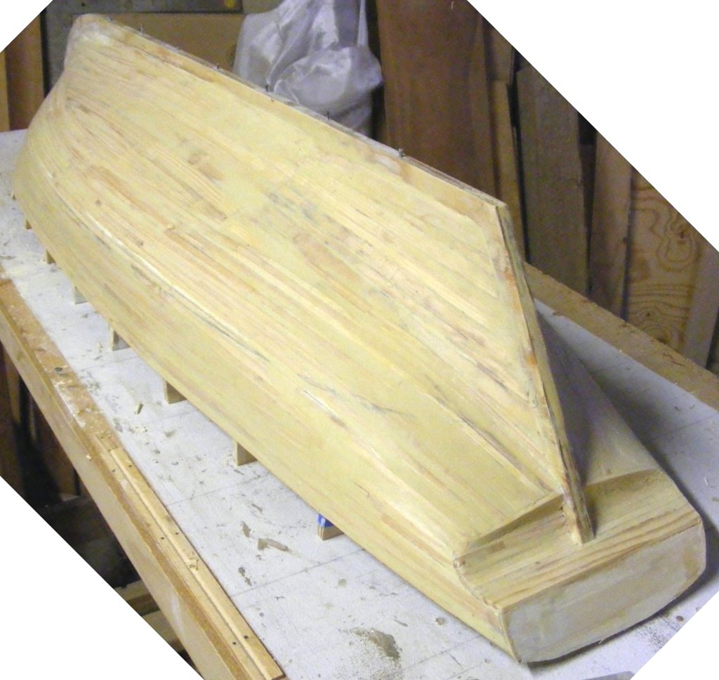
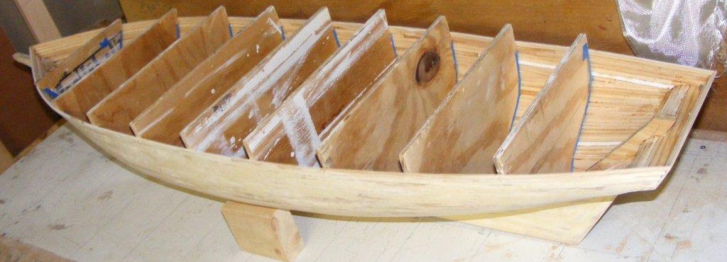
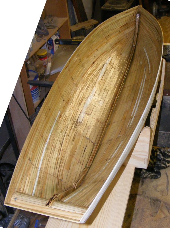
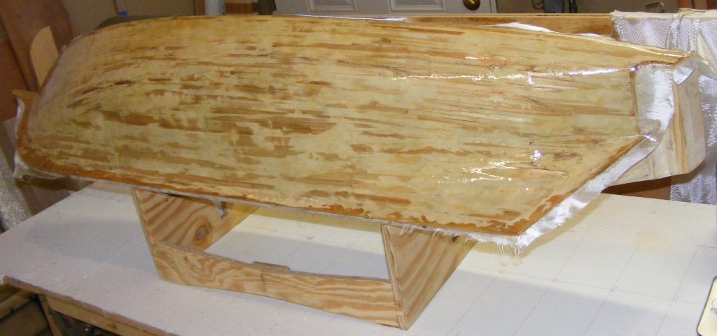
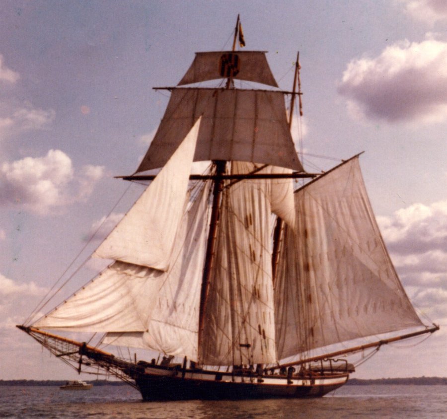
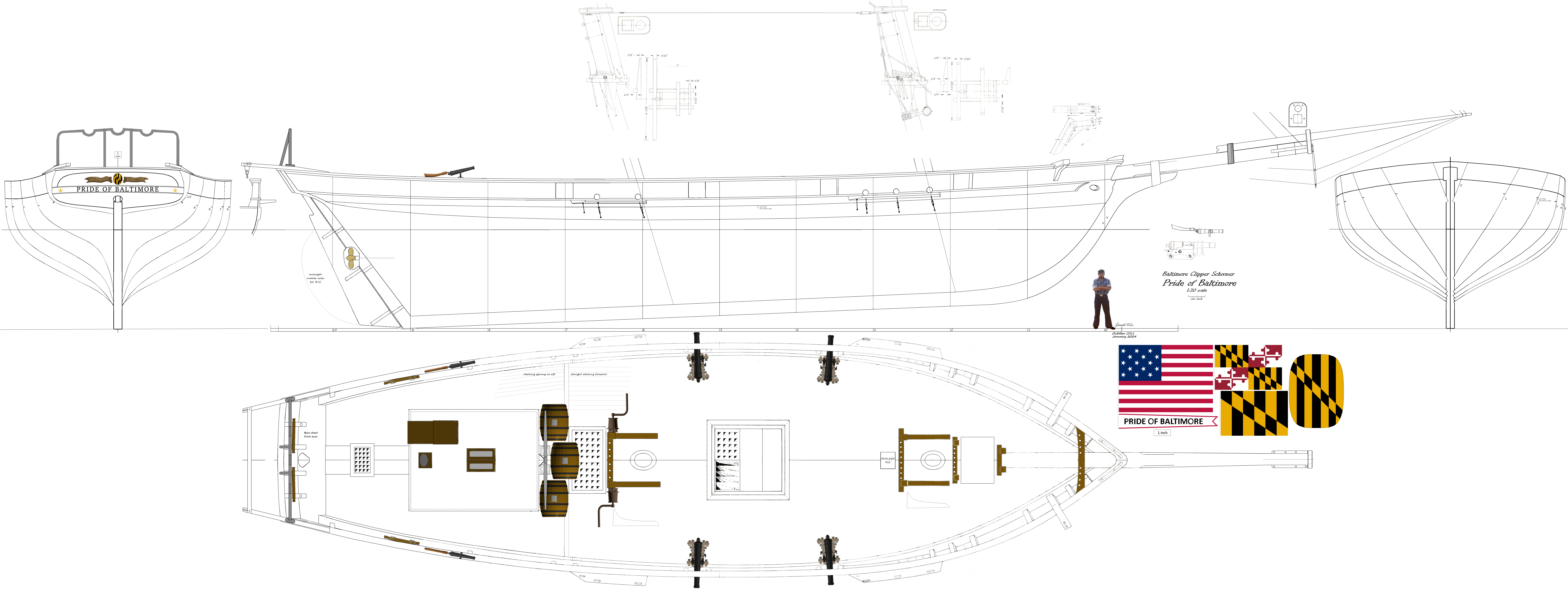
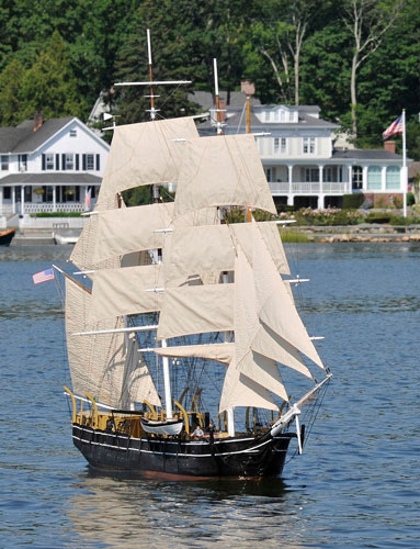
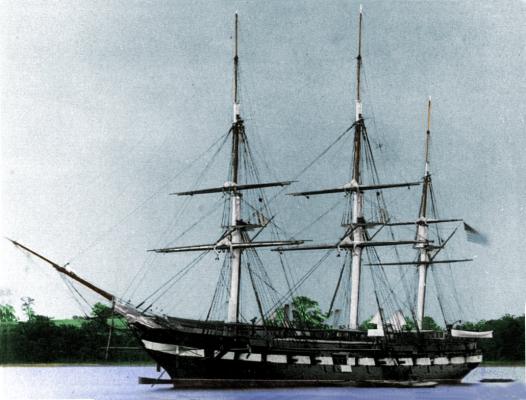
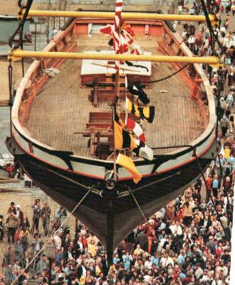
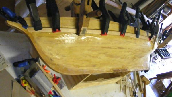
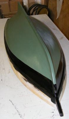
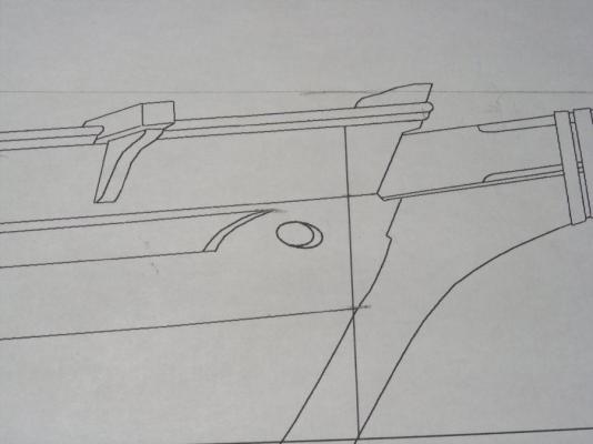
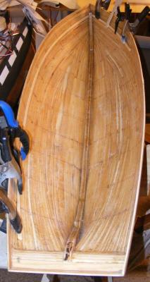
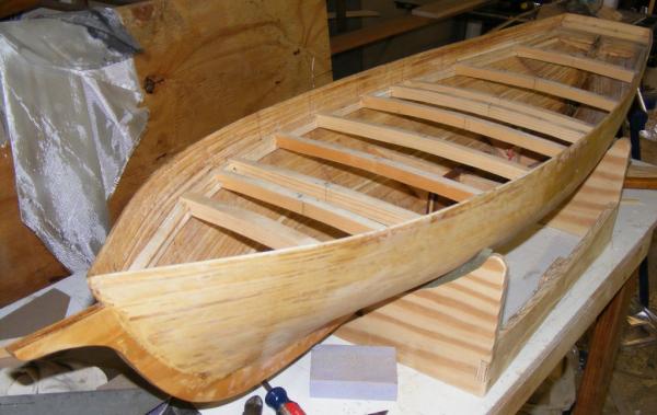
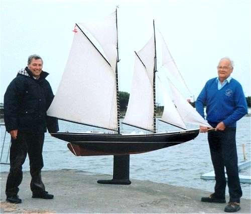
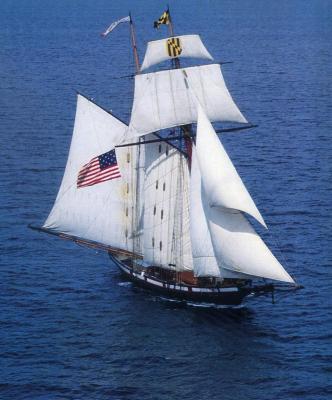
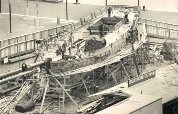
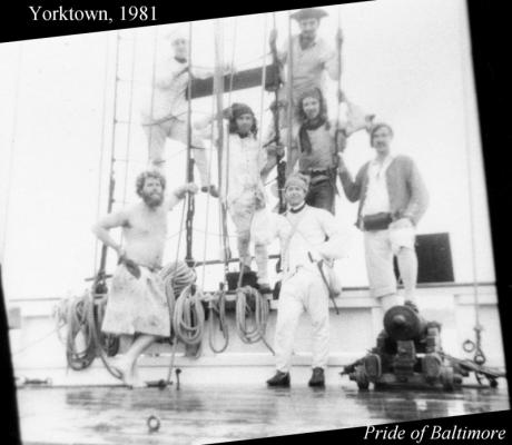
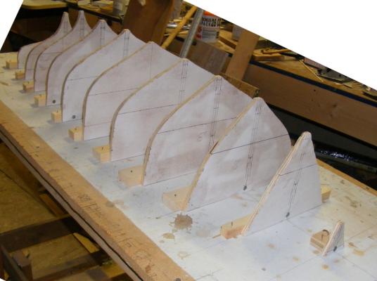
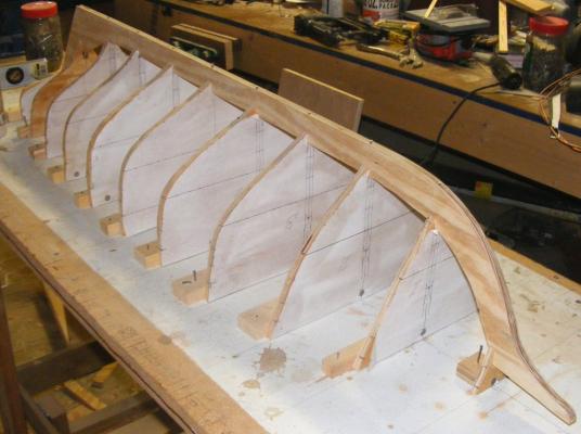
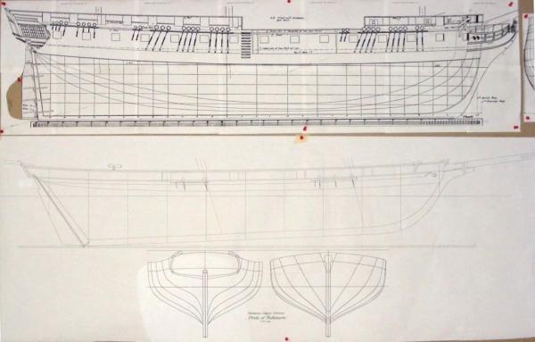
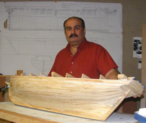
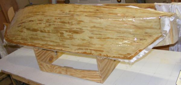
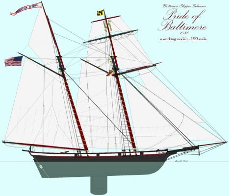
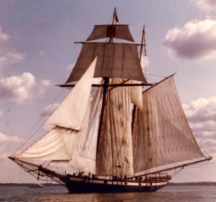
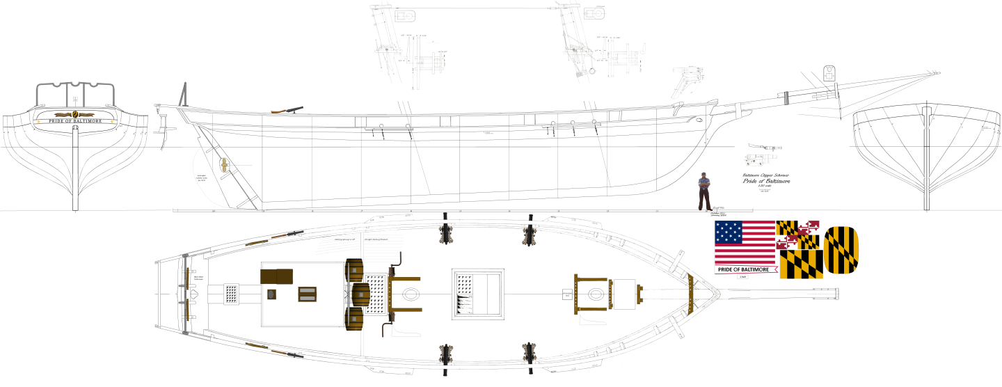
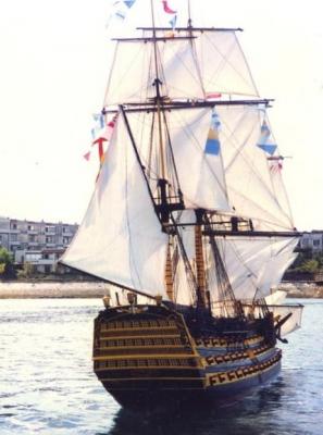
Pride in the Pacific 1982 In late 1976 I got a job as a laborer on a construction site in Baltimore's Inner Harbor. At the site they were building a Baltimore Clipper schooner named Pride of Baltimore. Pride under construction in November 1976, just about when I started there. Five years later, on my 21st birthday, I reported on board as Pride's newest crew member. I spent two months aboard the boat in charge of her guns as she took part in the bicentennial reenactment of the battle of Yorktown. Yours truly is at the top right, in the cocked hat. A summary history of the boat is available at my site, as is an album of the few photos taken during my time aboard. In 1982 I acquired a copy of her plans from Thomas Gilmer with the intent to build a sailing model, but I was young, moved around a lot and it just never happened. In November of 2011 I got to seriously thinking about actually building a model of Pride and figuring out what size to make her. The upper limit was as large, overall, as Constellation, but there was a lower limit also. I tried scaling her the same as Constellation (1:36), but looking at what she would need in terms of batteries, winches, servos, etc; I didn't see how I could fit the equipment needed to control so complicated a rig. I decided to make her 1:20 scale, as large as I could and still stuff her into a van or SUV. With her lines scanned and scaled up I printed her stations on paper. There were glued to 3/8" CDX plywood, cut out, sanded, etc, and stood up on the old building board Constellation was built on. A work in progress: every item I draw in scale gets added to this plan. There they stood for nearly a year. On November 19, 2011 I cut out the keel, mounted it on the forms and began planking. I learned my lesson on Constellation and fully planked the hull, but I taped the edges of the forms so the planking wouldn't be glued to them, and they could be removed - leaving me with full access to the very limited space. The hull was planked in pine strips 1/8 thick and 1/4" wide. They were glued to each other, but only pinned to the forms. The pins were akin to half-length straight pins and bent at the slightest look, making planking extremely tedious and hard on the fingers. I wasn't doing the next one that way. I also didn't spiel the planks, but just laid them on from the keel up, and the sheer down, leaving that football shaped hole to fill. The hull being glassed and painted, it wasn't an issue visually, except that it bother's me constantly. I'm not doing that again either. By Halloween, the hull was planked. The hull was filled, sanded, filled, and sanded some more. The aft-most form with the counter and transom forms was given a tap with the handle of a screw-driver and came right out. Soon the other forms followed, leaving the hull open. The inside was sanded and then painted with diluted Tightbond III to get into the nooks and crannies of the planking and glue everything up. It was then given two coats of poly resin. The stern post was too tall, a sign of advanced planning. I cut it down with a rotary tool - you'll see why later. The stern and then the sides were fiber-glassed with 4 oz cloth. Pride's plan compared to Macedonian's The concept I restarted the build logs for Constellation and Macedonian that were lost in the crash. There never was a build log for this model on MSW, but, what the heck, there is now.


- 79 replies
-
- 12
-
-
- pride of baltimore
- privateer
- (and 3 more)
-
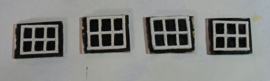
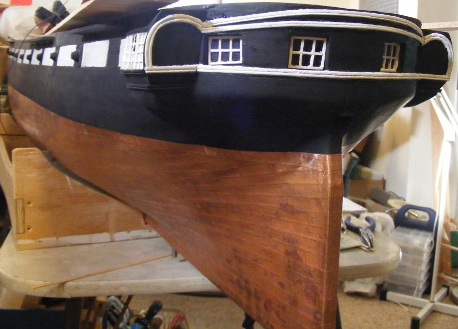
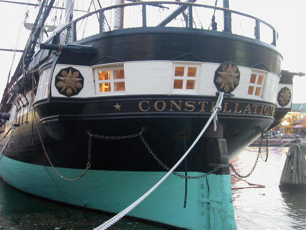
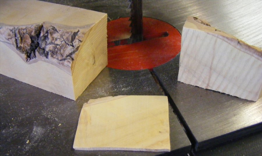
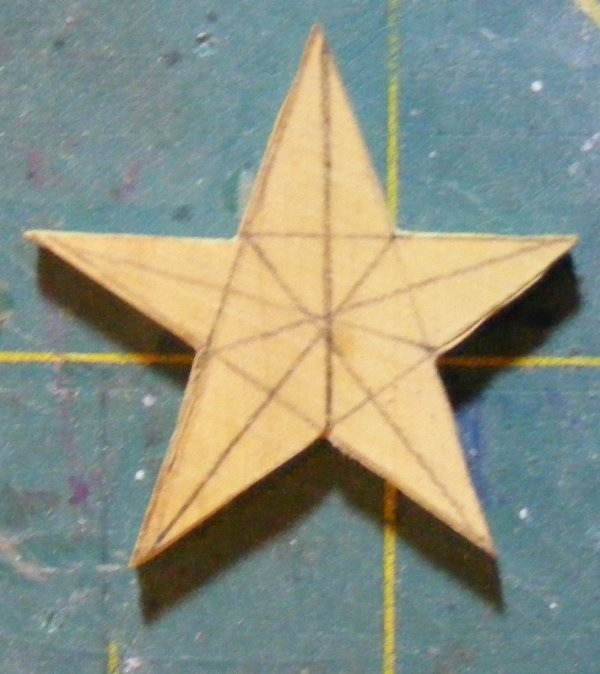
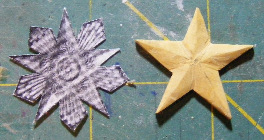
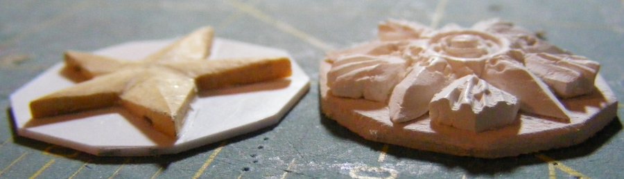
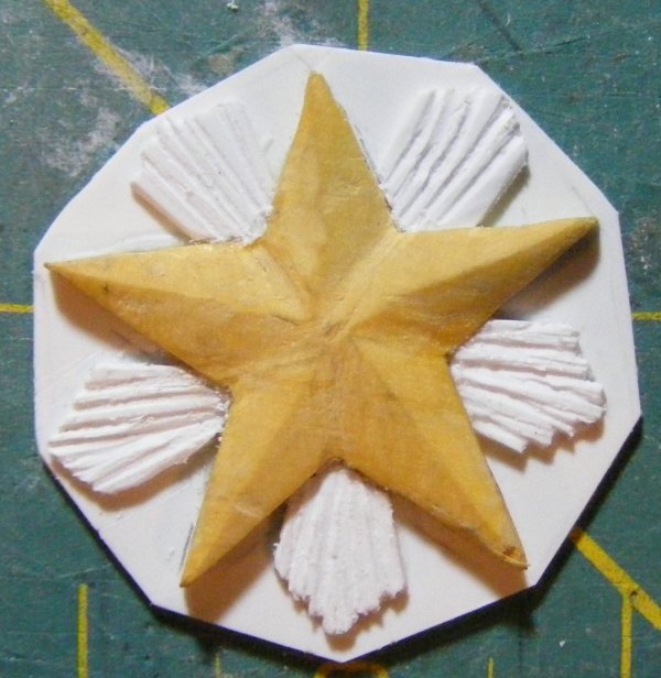
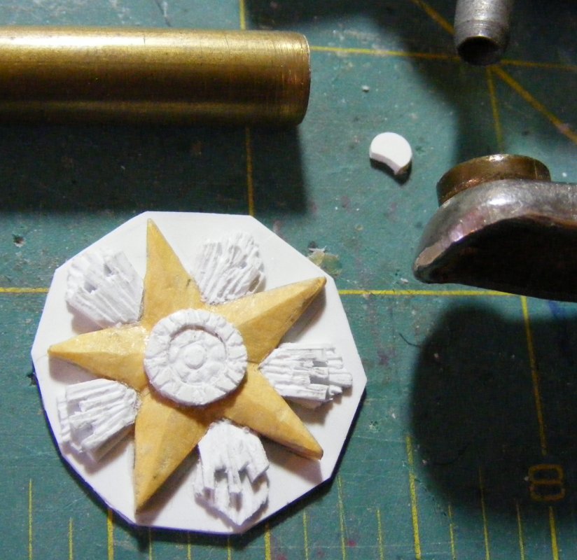
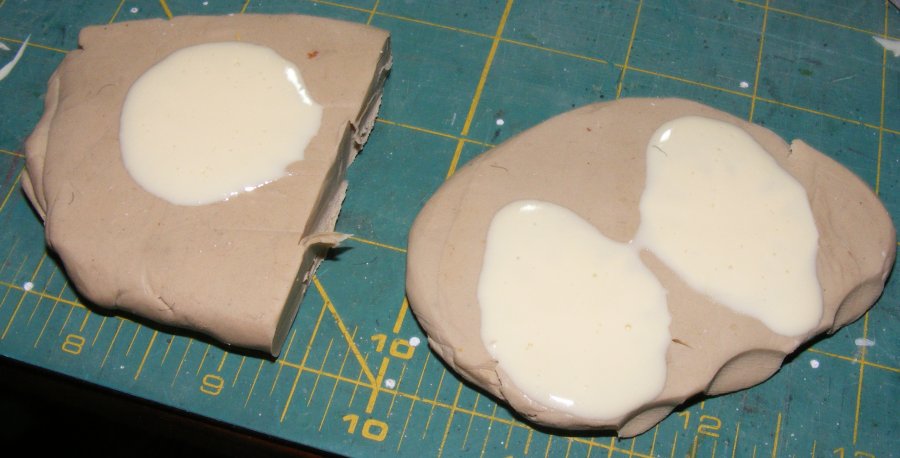
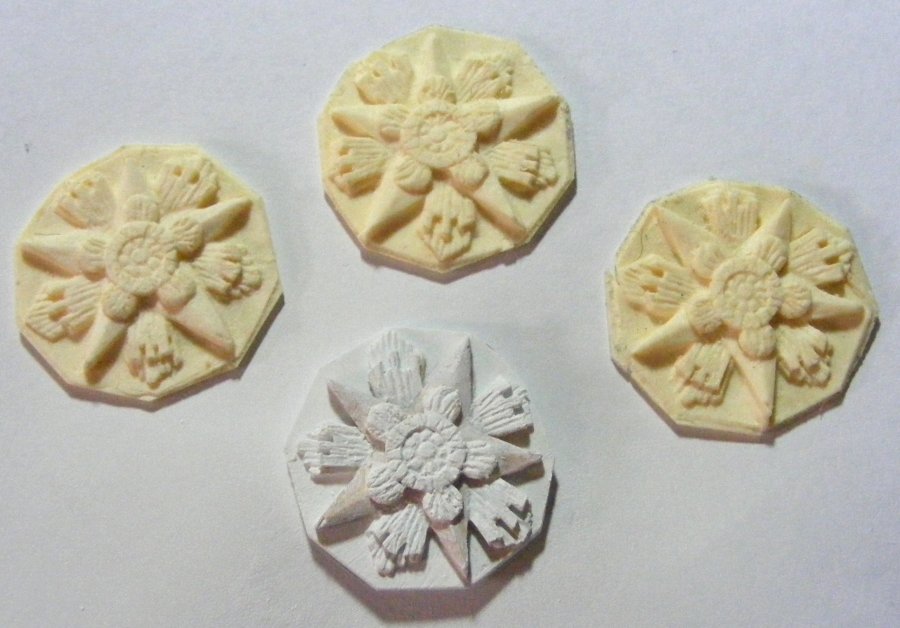
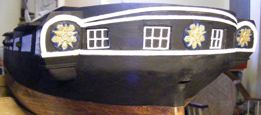
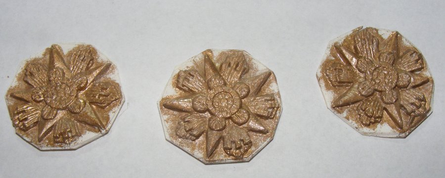
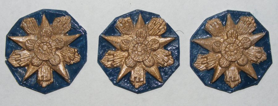
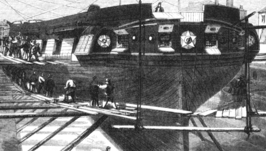
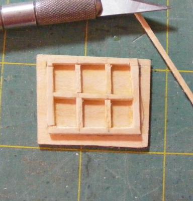
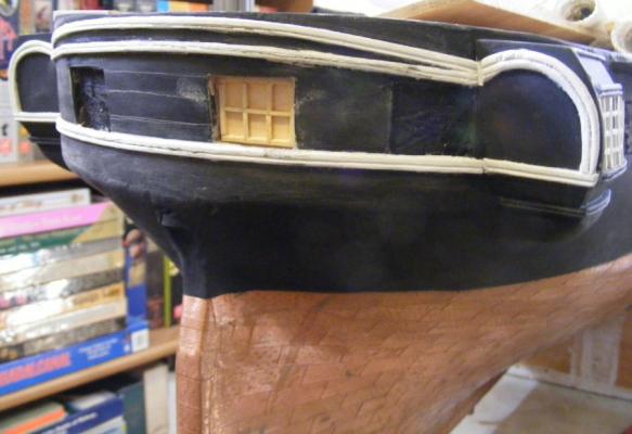
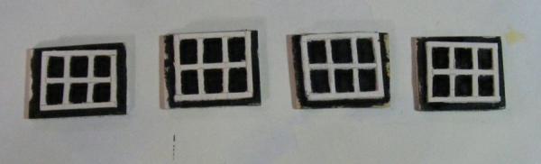
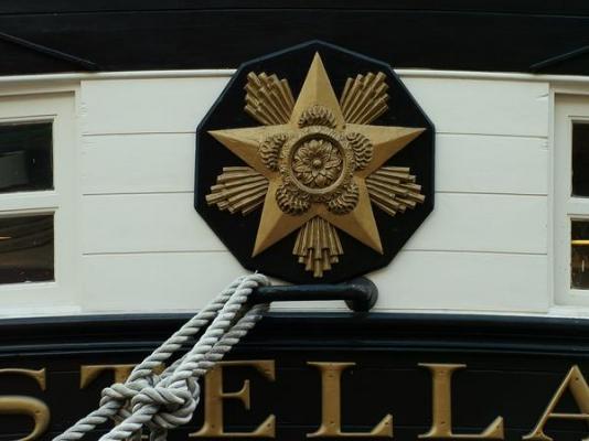
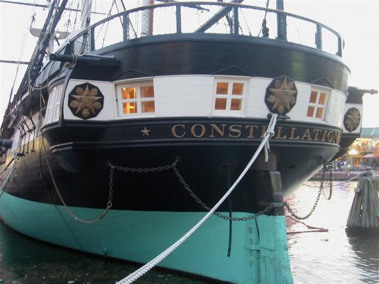
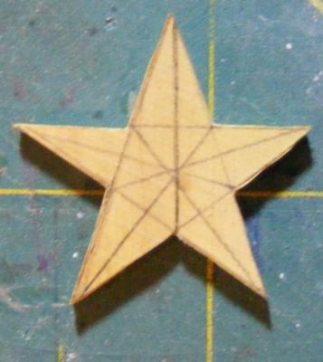
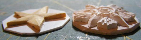
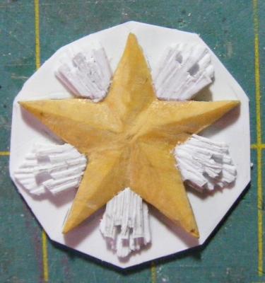
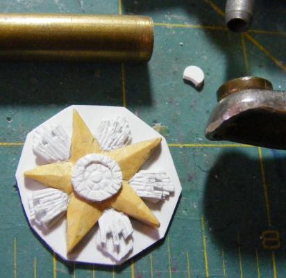
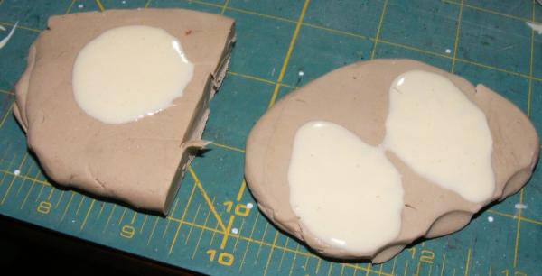
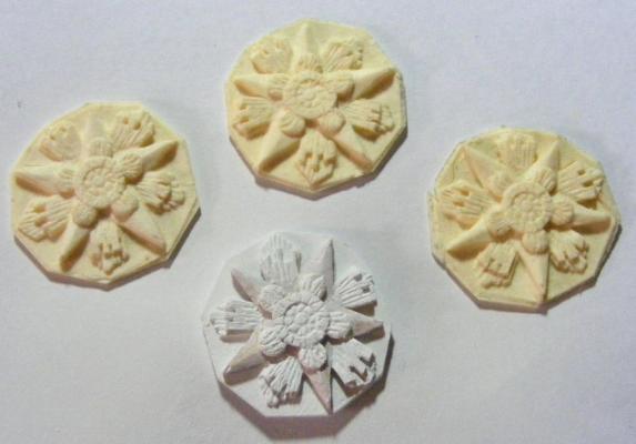
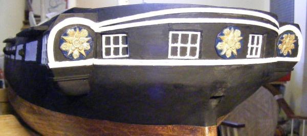
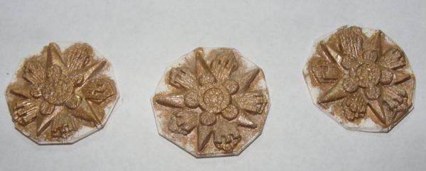
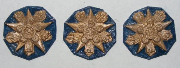
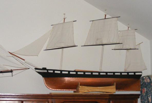
Stern Windows Further back, I posted a drawing of the ship in drydock in Boston Navy Yard (Charlestown) in 1859. Now I took another step toward that image. I had cut out the stern ports back when I cut all the ports to install the resin gunport lids, but I didn't cut all the way through. I thought I would just install the window frames into this recess, but the fiberglass matt surface just wouldn't get smooth. So I cut out a port and made a window frame to install from inside the hull. That looked like it would work, so I cut the rest of the ports, made more windows, epoxied everything in place, painted everything and Constellation no longer had a blank face, er, rear end. The "glass" portions of the windows will get several coats of clear gloss. I didn't use glass because there's noting to see through them and I didn't see the point. Medalions Since she was built, to this day, Constellation has had three fiery star medallions on her stern; her constellation of stars; one in the center and one each on the backs of the quarter galleries. So far as I've been able to determine, these medallions are the original set she had when she was launched. I tried carving one in Sculpty, but it was too bulky and thick. I had a little boxwood left over from a carronade I made for the Hornet project and remembering how nice it was to work with, I tried a different approach. I sliced off a slab of the boxwood and cut and carved the star. This was mounted on a sheet styrene backboard. Already it's looking better than the first attempt. Bit by bit, I added details carved in styrene sheet. When it was done, I primed it and then mashed it into some clay three times, poured a little resin in, and a few minutes later I had three pads of butter that looked like Constellation's medallions. These were trimmed, sanded a little, washed, degreased, and primed. The raised details were painted gold... The background was painted midnight blue. I examined the oldest photos where I could see these on Constellation and felt that there was a color difference there. Looking at common depictions of stars, comets, and shooting stars in period art and carvings, it seemed fairly typical to make celestial objects gold on dark blue backgrounds - so that's what I did. The medallions were then given a couple of clear coats and then epoxied onto the stern. As I mentioned on the chainplates, I decided to use wood screws to attach them to the hull, rather than through bolt them. To that end, I epoxied strips of oak inside the hull to give the screws something to screw into. I also put some fiberglass over the inside of the stern windows to make sure things were sealed up tight. looking aft from inside the hull. As of this date, this is where the model stands on top of a cabinet in a living room, waiting for the shop to get put together so work can resume.


- 553 replies
-
- 7
-
-
- sloop of war
- constellation
- (and 3 more)
-
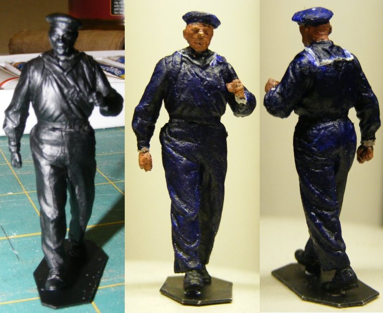
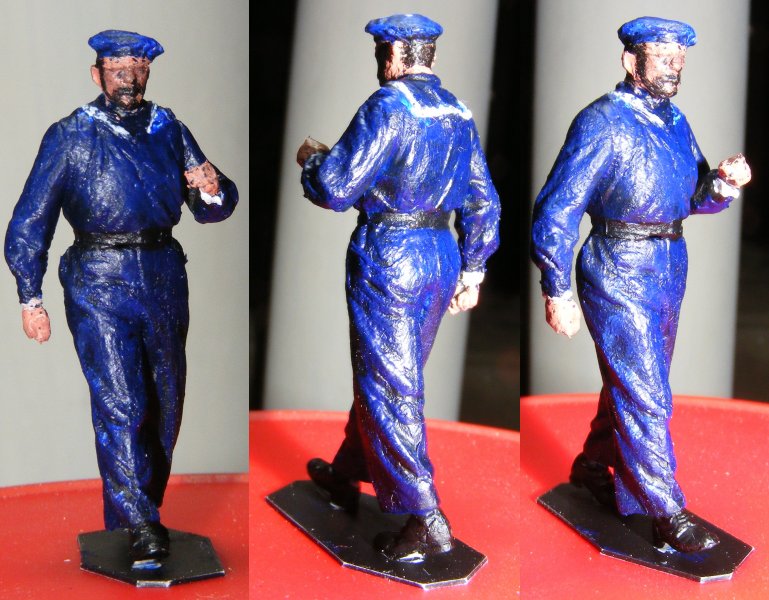
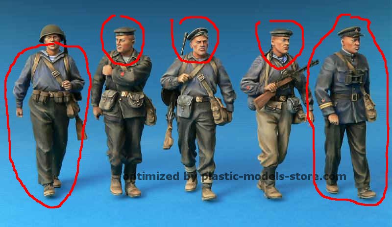
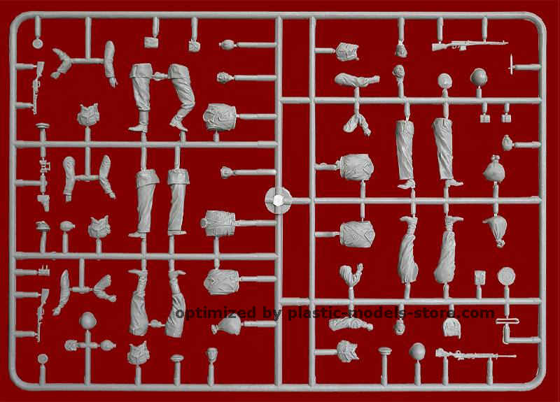
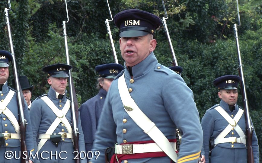
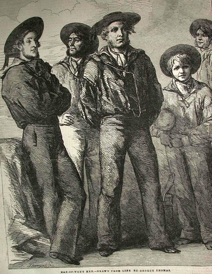
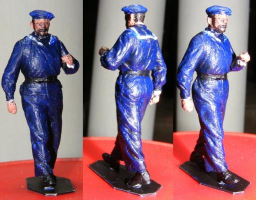
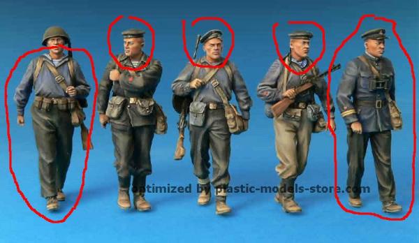
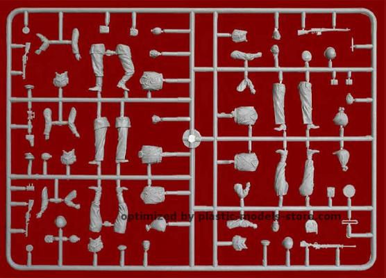
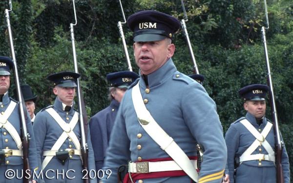
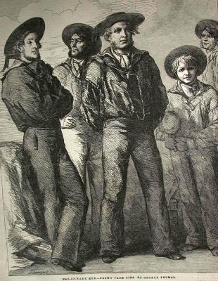
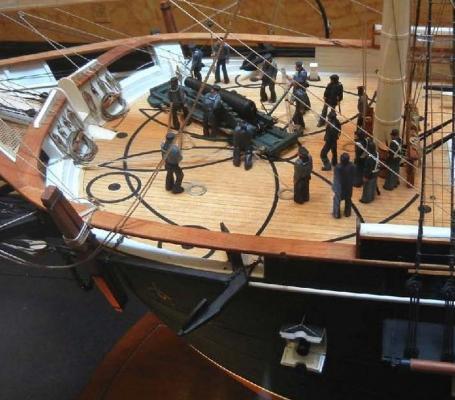
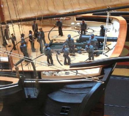
A working model without a crew, to me, looks odd. I'm not modeling the Marie Celeste, but, in fact, a warship, which tend to have pretty large crews. Constellation had a complement of some 20 officers, 220 sailors, and 45 marines. I don't intend to include all of them, but there will be some 30-40 figures visible, especially around the pivot guns. First, I have to determine what Officers, sailors and Marines looked like in 1856. The simplest are the Marines as I have reenacting buddies that do Marines of that period. Officers I haven't nailed down yet, and sailors are a bit like these fellows, except I've seen these boys IDed as both US and British Man-o-War men. It's hard to find images of US sailors in the mid-1850's, except some Japanese art from Perry's visit. I though the plethora of 1:35 scale military figures would make finding something I could convert easy - far from it. The closest I've managed are some WWII Russian sailors, but it was $5 for the set and I should be able to get a couple of basic figures to take a mold off of and clone a crew from them. From this I assembled one fellow you've seen in several images above to help represent scale, I call him "Ivan." He was painted with acrylics per the method found on the web site.


- 553 replies
-
- 5
-
-
- sloop of war
- constellation
- (and 3 more)
-
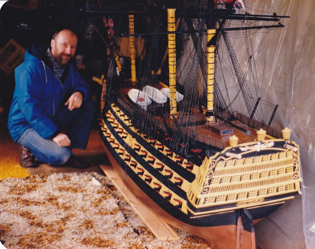
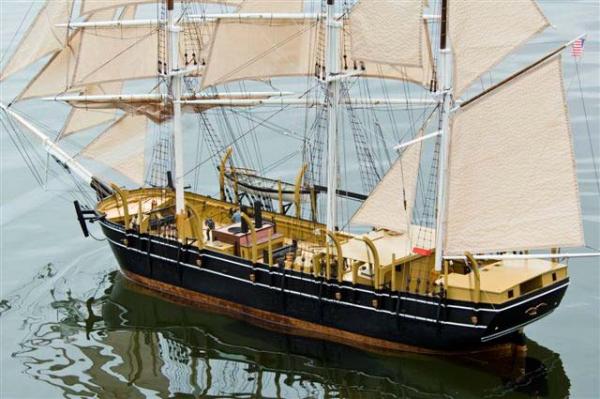
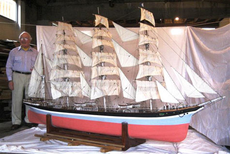
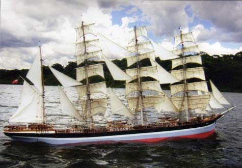
Thank you for the kind words. When I started this project the Internet was pretty new, to me at least, and it wasn't easy finding information, or other people doing such things. Since then I've come across a bevy of wonderful models. Some aren't much up close, but beautiful under sail, while some just boggle the mind at any distance. Victor, who built the Royal William mentioned earlier, built a Victory some years before, same 1;36 scale I think. "Bill Huizing (pronounced Hy-zing) of Summit, New Jersey in 2009 completed an utterly magnificent RC model of the Charles W Morgan whaler seen by visitors to Mystic Seaport." quoted from Mark Steel's column in DuckWorks Bill doesn't do the Internet" built the 1:24 scale Charles W Morgan I think you'll appreciate. There was a YouTube video of it sailing, but it's become "private" sorry folks, it was something to watch it sailing about in Mystic Harbor, a harbor I've sailed about in myself a few times. This little fella from Down-unda built himself the bark Sindia - now that's impressive - he can nearly get in it and sail it himself! The sailing and static pictures are all very nice, but I tend to go looking for the shots that show the guts, how they handled control, and how they transport these beauties! Guess I'm just an RC square-rigger geek.


- 553 replies
-
- 8
-
-
- sloop of war
- constellation
- (and 3 more)
-
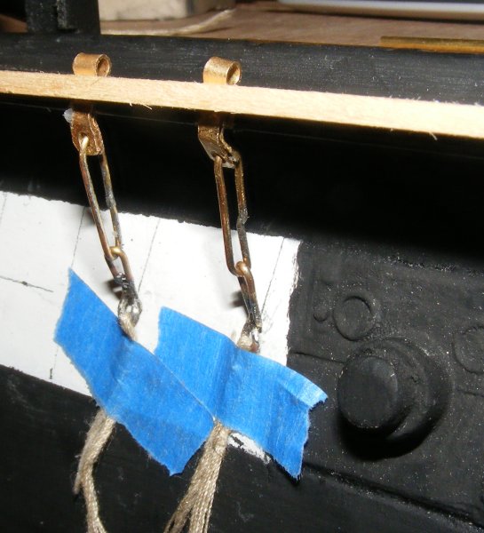
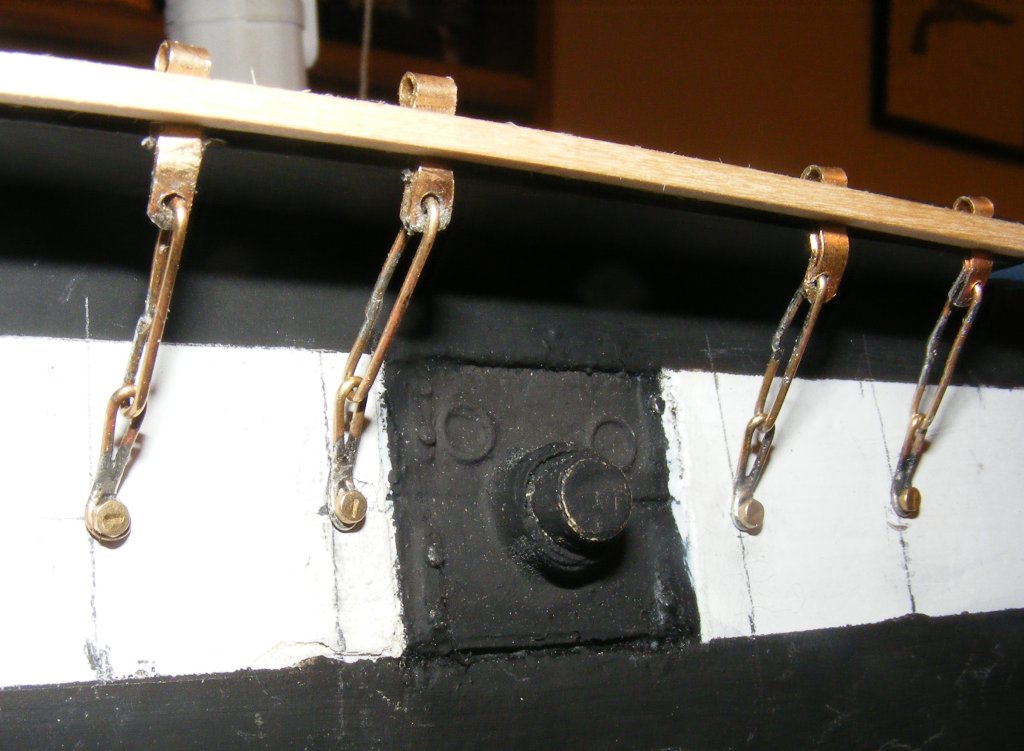
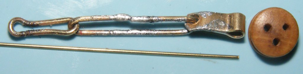
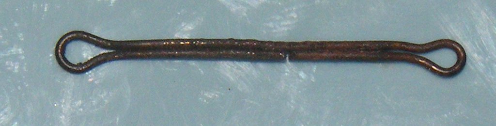
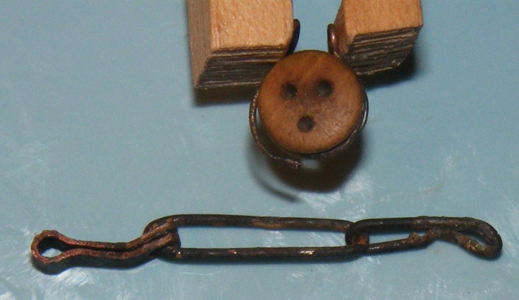
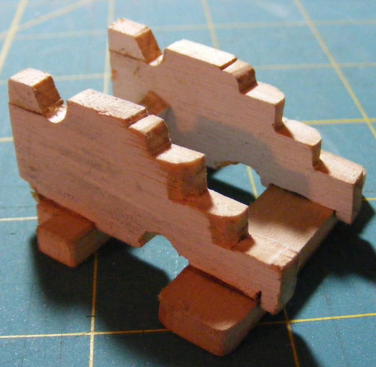
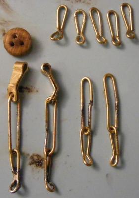
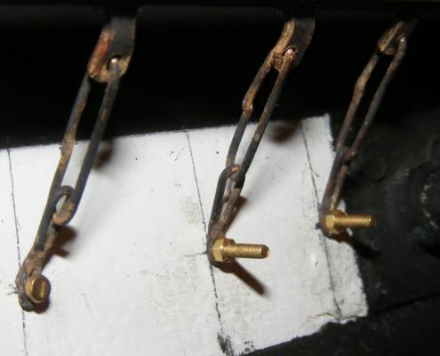
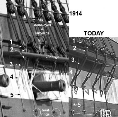
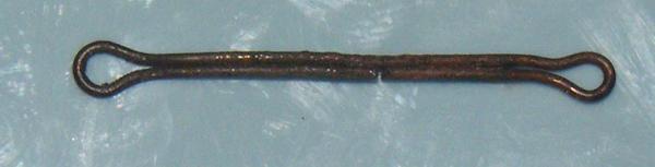
Now we come to the chainplates. I was initially going to bolt them through the hull, and that requiring access inside the hull, would delay getting the deck on, which, in turn, delays getting on the deck details and hammock rails, etc, ie: finishing the darn thing. Instead of bolting them, I will use brass wood screws into an oak backer inside to attach them to the hull. I feel this will have the required strength and allow them to be removed, if need be, for repair or replacement. Riveting them, as the originals are, would be too much trouble to deal with at this scale. Constellation's chain-plates consist of five basic parts A strop that wraps around the lower dead-eye and bolts to... a link strap that lays against the channel and is connected to... an oblong iron link that is connected to... another link that's shaped like a bent exclamation mark (I call it the "pinched-link,") and pinned to the hull by a... dog-bone shaped, half-round, iron backing-link that is riveted to the hull and spreads the load. The ship appears to have retained her chain-plates through the years. What's on the ship today appears to be the same as the earliest photos where they can be discerned. I'm reasonably certain what's visible in the 1914 photo is correct for 1856 - and unable to find evidence to the contrary - that's what I'm going with. I'm making the chainplates from brass sheet and rod in the same layout as the originals. This way they should function well enough for the model while looking correct, and to scale. It's times like this I wish I could manage some photo-etching so I could make a whole pile of the link-strap (#2) at once - they really are quite a pain to make. The pinchlink isn't too bad; I wrap it between two pins in a block and literally pinch it. Soldering I do with soldering paste and a micro torch. They will be painted, but I blacken them to give them a sort of primer coat first. I haven't had much luck making the strop. The real ones are doubled iron rod, but brass rod small enough to double doesn't like being soldiered. I plan to try it with a soldering iron and see if that works better than the torch. The backing link is a half round piece of iron with the flat against the hull. I haven't figured out my approach to this part yet, though it would be nice to PE a whole set of them and be done with it. So far I have 46 each of parts 2, 3, and 4 shaped and waiting to be soldiered.


- 553 replies
-
- 3
-
-
- sloop of war
- constellation
- (and 3 more)
-
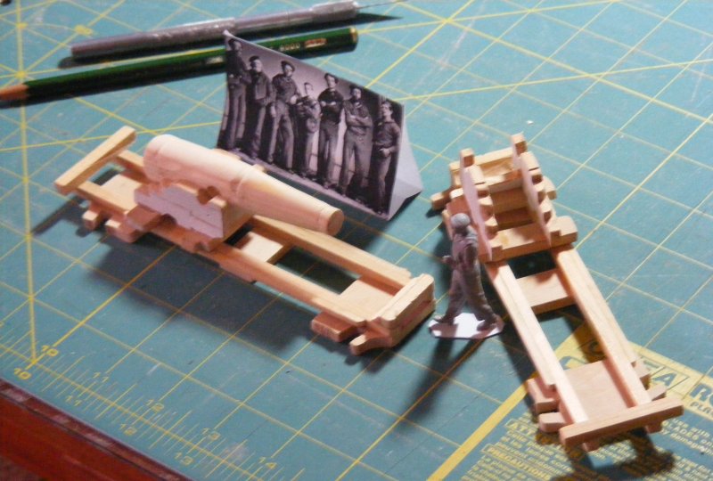
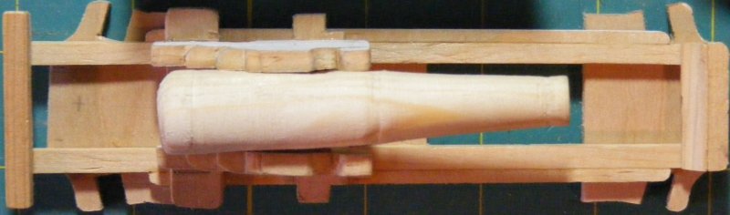
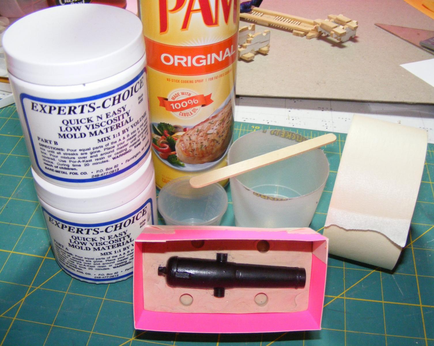
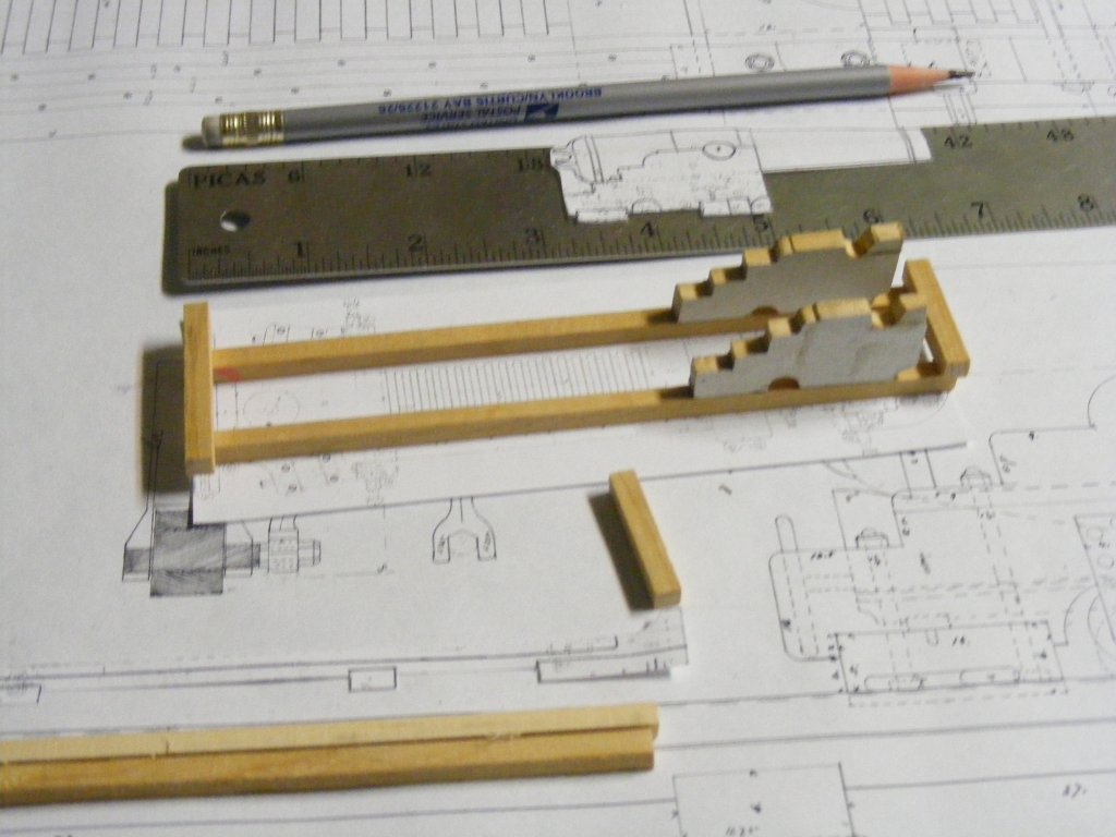
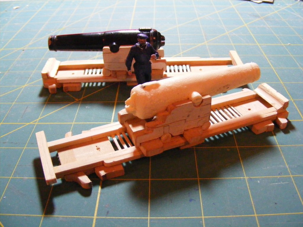
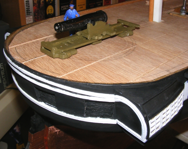
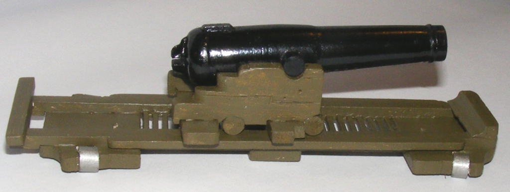
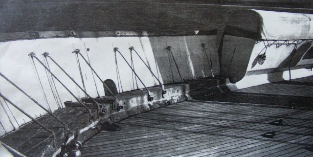
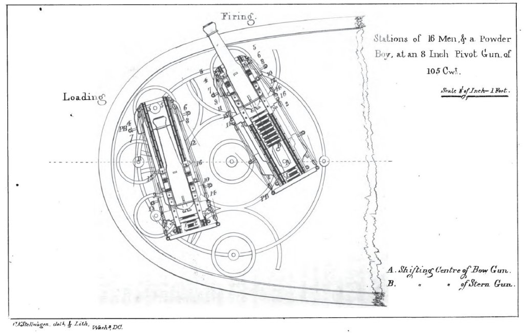
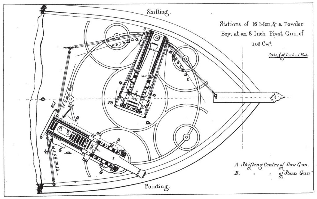
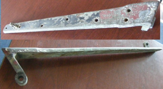
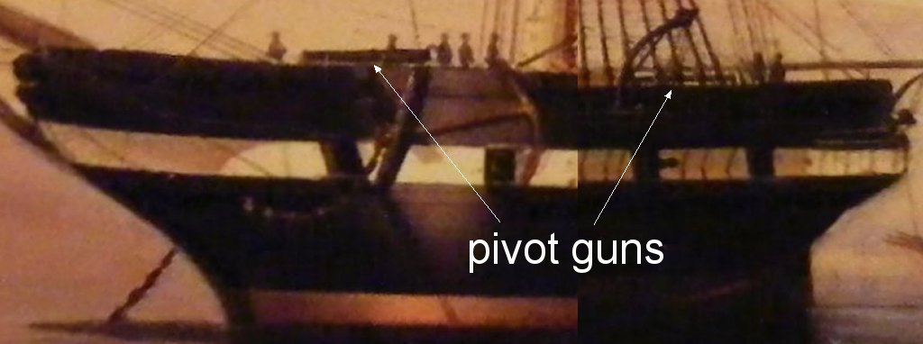
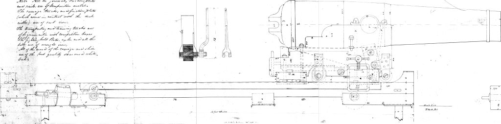
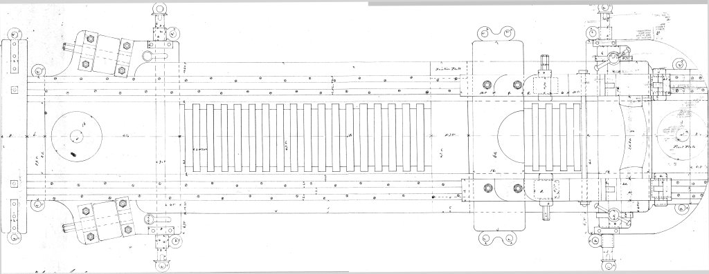
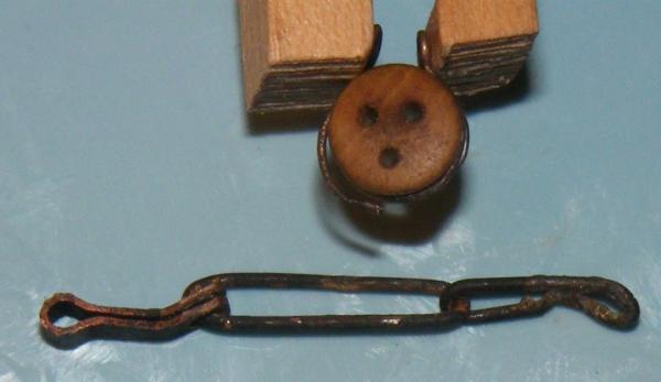
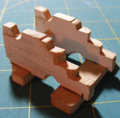
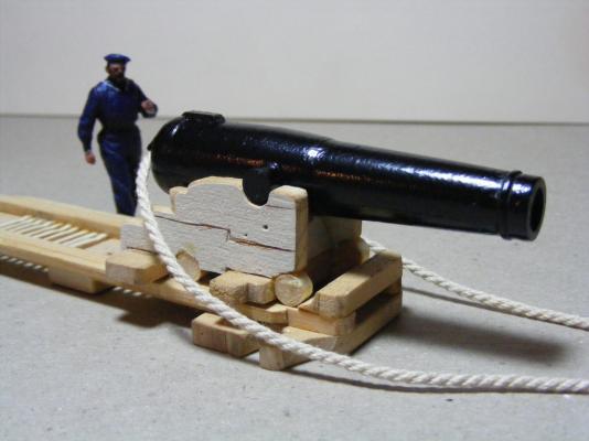
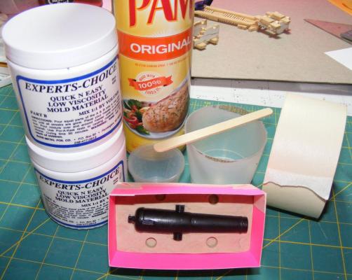
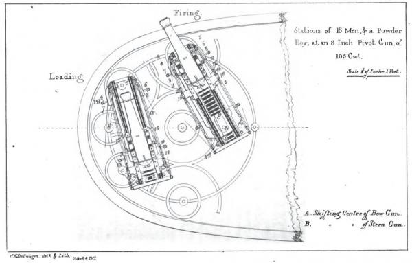
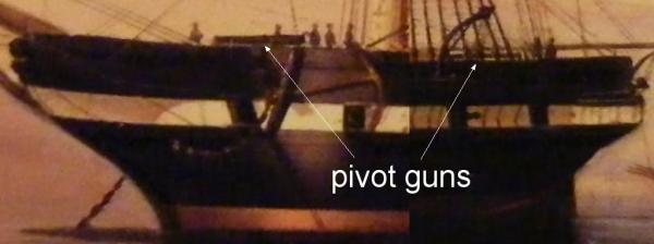
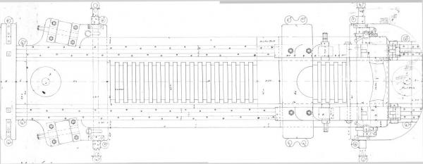
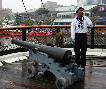
Constellation was originally fitted with two 10" shell guns mounted on the spar deck and designed to pivot. They can be seen in deSimone's 1856 portrait of her at Naples. Her bulwarks where the guns were mounted, were made into panels that could hinge down, out of the way as seen in the sketch of her stern in 1859, and a photo of the bow portion which she retained right up into the mid 1950's, when she was brought to Baltimore. The stern portion were reduced so only the panels at the quarters remained, and then at some point they were removed entirely and a "solid" bulwark installed. Some of the bronze hinges for these panels still exist, though the ones for the stern are long gone and many for the bow are missing. The guns themselves were mounted on carriages that slid on a chassis that could be pivoted on either end, or in the center. Iron tracks were screwed on the deck to keep the chassis from tearing it up. What pattern these tracks were laid in I've yet to discover. The restoration folks say that somewhere they're referred to as "circles," but I've read accounts from the Kearsarge that refer to them as "circles" or "traverse circles " where photos of her deck show something more complex than a simple circle, but more akin to what's seen on this model of the sloop of war Savannah, razeed from a frigate. In fact, manuals printed prior to the Civil War are, I believe, much closer to what Constellation probably had: I actually started making these guns before work resumed on the model in 2009. I didn't have a lathe yet, and tried turning a barrel on my drill press, which didn't turn out well. My friend Dan, following my build on RCGroups, offered to turn a barrel for me and sent me a lovely piece of work. I fined it up and added some details to it, then made a rubber mold and a resin casting. The mold got bubbles in it and the casting came out looking like the gun was recovered from the bottom of the ocean. I'll have to come back to that experiment at some point. The chassis for my carriage was a modified version of the plan I acquired from the Archives for the steamer Mississippi's guns. At the time I was under the assumption that rollers were required at either end to function on a single circular track. The manuals, showing the exact same chassis, show that is not the case - so these will be rebuilt, or replaced, with correct ones at some point. These guns were replaced with a pair of Parrot Rifles at the start of the Civil War; a 30 pounder forward, and a 20 pounder aft, both on mounts very similar to those of the 10" shell guns. Plans for these mounts are also available at the National Archives, and are what the restoration people are hoping to install someday. They already have a 20 pounder Parrot tube on board mounted on an ordinary truck carriage. Note the size of the 20 Parrot compared to the model shell gun as compared to the men.


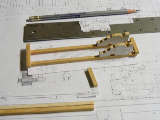
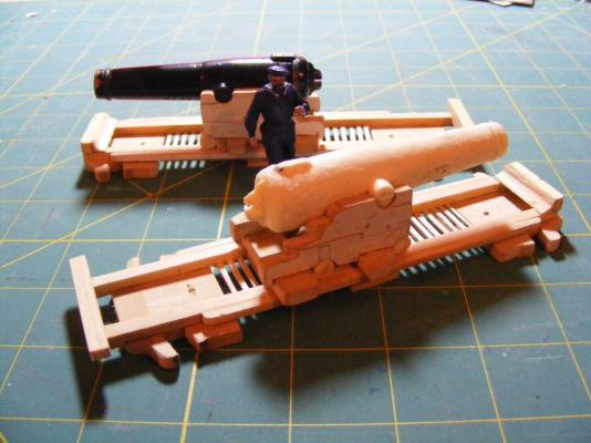

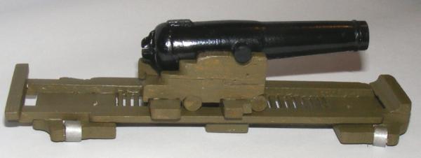


- 553 replies
-
- 5
-
-
- sloop of war
- constellation
- (and 3 more)