HOLIDAY DONATION DRIVE - SUPPORT MSW - DO YOUR PART TO KEEP THIS GREAT FORUM GOING!
×

JerryTodd
-
Posts
875 -
Joined
-
Last visited
Content Type
Profiles
Forums
Gallery
Events
Everything posted by JerryTodd
-
 The thumb thing, BTW, is a thumb stall. It's not so much to protect the thumb as to seal the vent. When the sponge or rammer is sent into the barrel it pushes air and you don't want that going through the vent as it can ignite left-over embers and cause the new cartridge to ignite as it's rammed home. The thumb-stall is a very important safety job and isn't just laid on the vent. It's pressed on and twisted so the tip of your thumb is pointed at your right hip with your elbow pointed to the right as you face toward the muzzle.
 -
setting and brailing sails remotely almost always involves drums and winches which means there must be a full loop with constant tension or something will snag and jam or break - ie: downhauls pulling as haliyards let out equally. There are ways of dealing with all of this, but it requires an increasing amount of mechanisms below to do the job, and this model just isn't that big and has a lot of structure in it taking up space and weight. Add to that designing deck access to get at and service those mechanisms that's watertight. If it means that much to have this feature, you might attach the tops'l to the gaff and it's haliyard hauls gaff and course together, and they come down together. It won't be scale and eliminates the gaff throat and peak haliyards (the tops'l itself replaces those functions), but it would get the job done simply and efficiently.
-
I think you'd need mechanical fastenings for ebony
-
Gaff tops'l I, as you say, treat as an extension of the course, treat it all as one sail. Stays'l that have to cross a stay are another matter. Most models I've seen don't have stays'ls, and those that do either keep the clews above the stay, and often just don't bother with controlling the sheets, or just sheet them to the centerline and leave them that way.. One idea I gave some thought was a bit of elastic that would raise the clew just over the stay when the sheet was eased, but this too may be more trouble than it's worth. On Pride I'm leaving off the fisherman stays'l because it would interfere with the fors'l far too much and is just too complex to try to handle remotely on that rig. Trained squirrels, BTW, are also not feasible as they tend to gnaw on the model and fill the hold with nuts. More details on Pride's control systems will appear in my MSW build log for her, rather than clutter up Bedford's log. I've never used a bilge pump. I usually toss a feminine napkin in the bilge to soak up anything that gets in there and leave the hatches open for a while after sailing to let everything dry. Anything catastrophic a bilge pump wouldn't keep up with anyway. I also sail in salt water which little pumps don't stand up to for long.
-
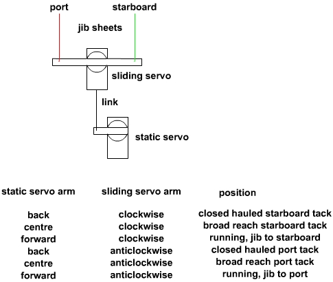
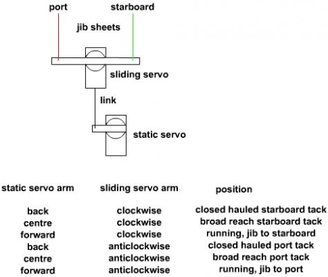
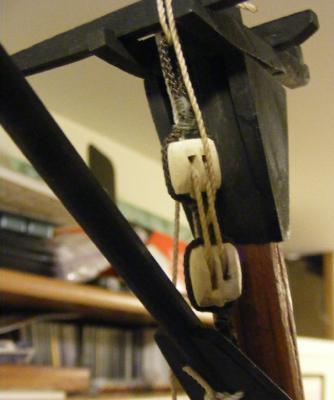
Here's a quick post with overlapping sail sheeting ideas, just tossed together... Any one that sails knows when tacking, simply put, you let fly the lee sheet at helms-a-lee and take in the new lee shet after the heads'ls across the wind/centerline. Accomplishing that in a model isn't as easy as it sounds. For one thing, remote set-up don't tend to work well with slack. Slack lines tend to snag things and there's no one aboard to clear these snags when they occur. There's also the issue of space in the hull and access for installation, maintenance, and adjustments. Servo arms long enough to pull the required length won't usually have the room in the hull to do it. Winches don't have this issue, but have issues all their own - especially with slack. Typical way of handling overlapping sails with a winch from Dan L: A servo arm set-up from the late Jimmy James: A two servo design. One servo pulls the sheet to port or starboard, the second servo moves the first servo itself to let in or out the sheets, from someone on Model Boat Mayhem forums: My playing with the above idea, but with one servo. Instead of a servo sliding the other one fore and aft, the servo slides itself via a line to the other side of the arm. The sliding sheet: the sheet slides through the clew until a knot pulls it over the stay. Sheet doesn't require a lot of tension if used with a servo arm, if with a winch, that's another issue Someone posted this on RCGroups a while back and it looked really promising to me, but... I've mocked this up on the bench and couldn't get get a pull of much length. It's also tough to start the arm from center as the servo hasn't as much leverage. Trying to make this work within the space available in the hull hasn't been successful but I'm convinced something along this line is the answer.


-
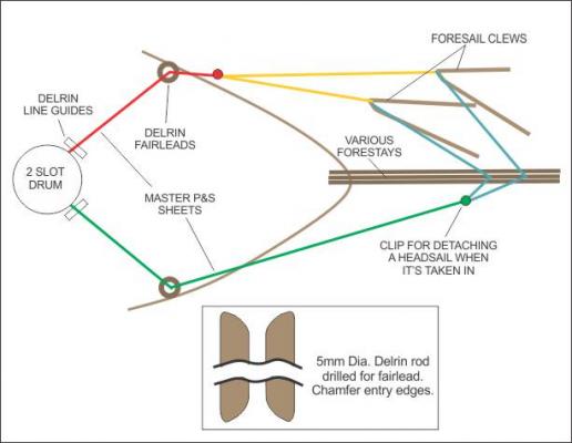
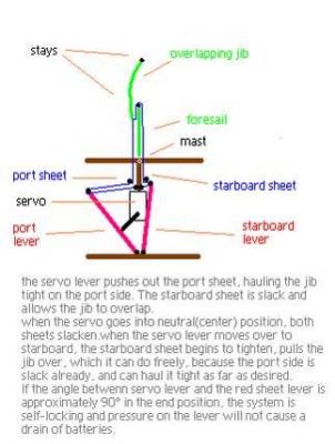
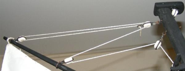
On RC models you'll find a great many modelers don't want to deal with the mechanics of overlapping jibs; that is having to drag the heads'ls across the forestays. One manner of dealing with this is the clubbed jib, as shown above. This may work well for your forestays'l, but the jib is another matter. Some deal with this by raising the clew of the jib so it doesn't actually overlap the forstays'l and passes freely from side to side clear of the stay. This is sheeted through a ring made-off to the forestay where the clew crosses it and run down to the bowsprit and back to the servo in a way that doesn't interfere with the forestays'l. The jib then actually sheets to the forestay. Another option that may work for you is a continuous loop type sheet that runs from a winch or shuttle set-up, through the clew of the jib, and back to the other side of the winch/shuttle. A pair of knots in the sheet on either side of the clew grab the sail and pull it over as the sheet in pulled. The knots are spaced so they sheet in the sail snug on either tack. This gives you a jib that overlaps per your sail plan and work better if the sheets go to the bulwarks/rails like the real vessel's instead of the centerline where modeler's tend to put them. There are other ideas for dealing with overlapping jibs, but most require more mechanics to achieve, like two servos, etc. I've been playing with some ideas for my Pride because I not only have three overlapping heads'ls to contend with, but an overlapping fores'l, running main forestays, and running backstays - and darn little space in the hull to put a lot of mechanisms.
-
Add to that that any hole thru the hull should be over drilled, filled with epoxy, and then drilled to size so there's no chance of water getting to wood.
-
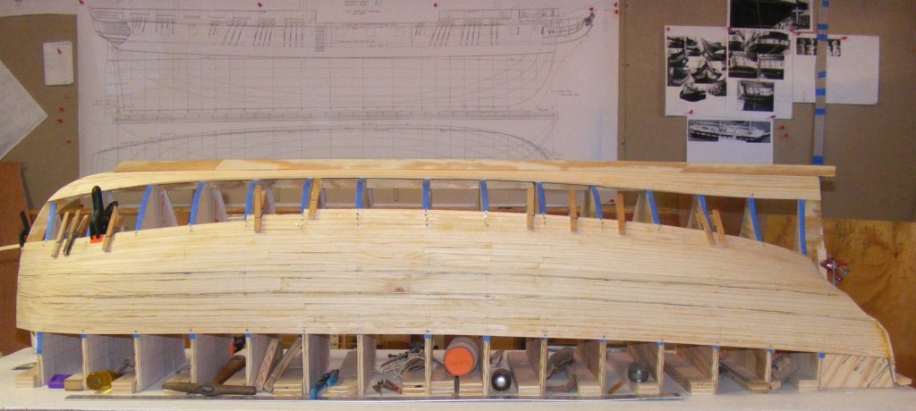
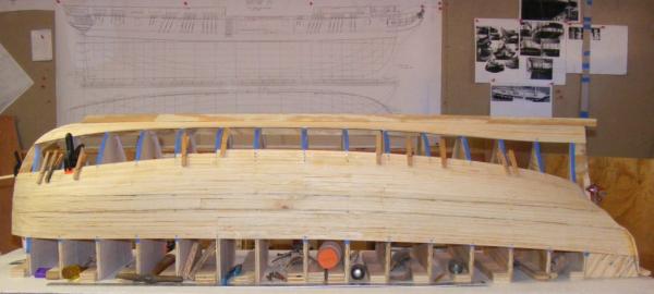
My build logs are back online and linked in my signature, I suggest the Macedonian as the best example; but simply put, I build a wooden hull, and glass it outside, resin it inside, all done. I build with scrap wood and planking cut from 1-by pine boards, usually 1/8" thick x 3/8" wide and 16" to 24" long. Cheap, but it gets the job done strong, fast, and light. You can fore-go the layer of glass, but even epoxied planking can open a seam with wood's movement unless you do a proper cold-molded hull, the layer of 4oz glass make's that point moot. My next hull will use balsa instead of pine in the same construction method. $20 at Home Despot gets you a quart of poly resin and a couple of yards of 4oz cloth from DuckWorks will run maybe $15. You can't look at Gucci-System for less than $50. Impress with your workmanship, not your wallet.
-
I build my hulls with Titebond III
-
Where Do You Keep Your Working Plans
JerryTodd replied to BubbleHead's topic in Modeling tools and Workshop Equipment
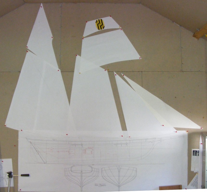
The prior owner of my house used the shed for his band, and lined it with Homosote board, foam rubber, and carpeting. I pulled out the foam and carpet, but the Homosote walls were great for pinning things up on. Constellation and a smaller Pride plan pinned up on the wall. Pride's full sized sail patterns also got pinned up on the wall. Macedonian on the wall and the bench. Now I've moved and haven't re-set up my shop yet, but I do intend to leave a big wall space to continue this practice.
-
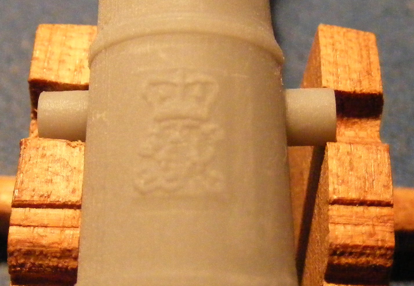
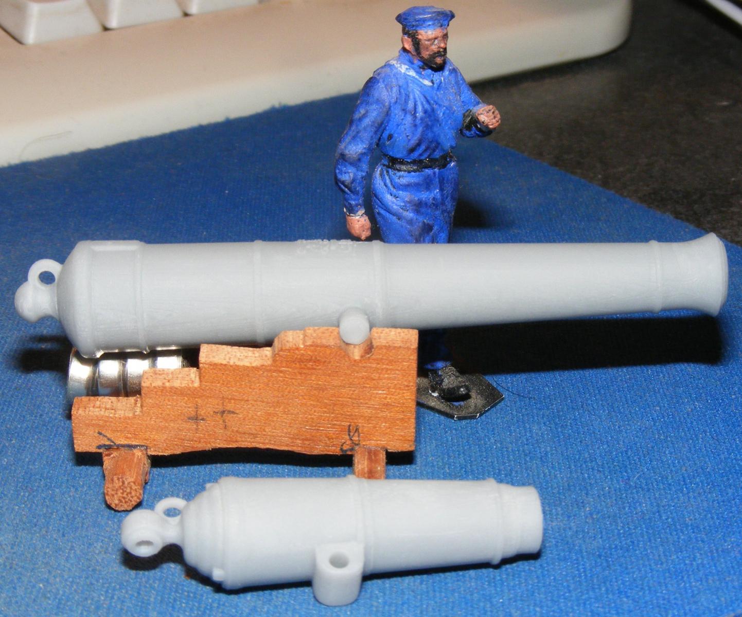
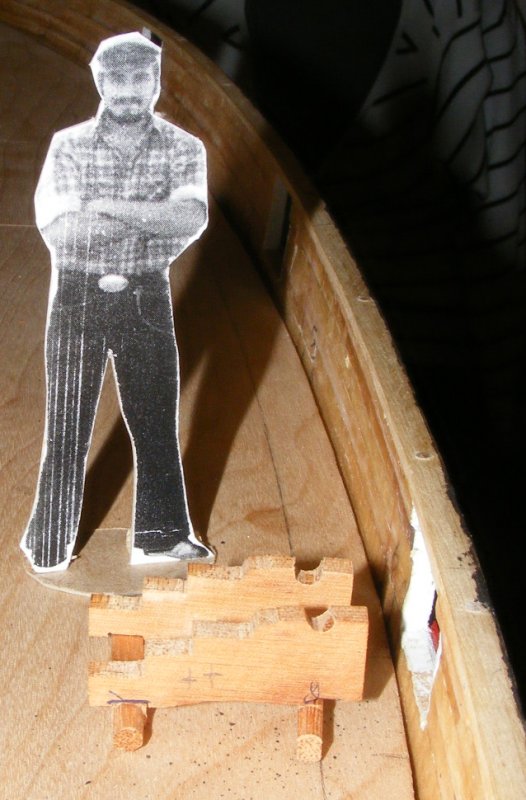
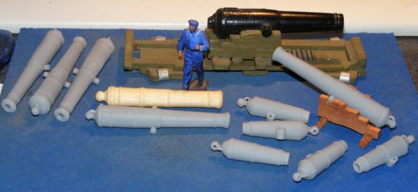
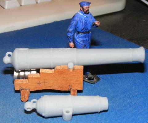
The 3D printed guns arrived in the post; 5 32 pdr carronades and 5 Blomfield pattern 18 pounders. These I'll make a mold from and cast the model's guns in resin - 5 at a time. 4 extra long guns will be modified a little to serve as Pride's six pounder tubes. Be sure to click on the image for the larger version where you can see the details! Constellation's pivot 10" shell gun and Ivan for scale (Ivan is 2" (50mm) tall) Wooden turned tube and carriage for Pride. HM's crest on the 18 pounders: Ivan and the Macedonian's guns:

- 97 replies
-
- 7
-

-
- macedonian
- frigate
- (and 2 more)
-
I would have liked to cold-mold the hull, that is planking in layers of veneers basically making a boat-shaped piece of plywood, but veneer is hard to find and very expensive here in Maryland.
-
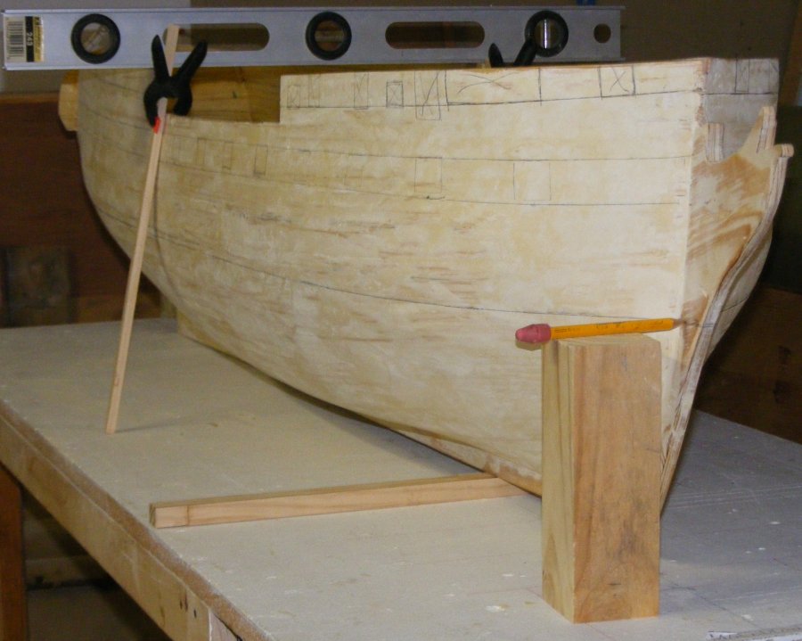
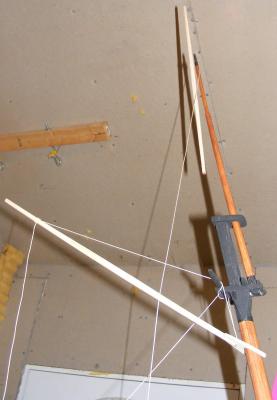
I level the surface the model sits on, in this case the build table. This is the base. The waterline is marked at the bow and the stern. I measured up the sternpost from the heel for the aft mark, and propping the hull so that it was the right height from the base at a certain station, measured up the stem from the base for the forward mark. In the picture you see a stick under the keel holding the bow up. I measured from the heel aft, going forward on the plan to where the keel was the height of my stick above the baseline, 3/4" in this case, and simply placed the stick so it's aft side was at this mark on the keel. The hull is then securely propped so that both marks are the same height from the base. The hull is also leveled side-to-side using a bubble level - that's why the base has to be leveled first. If your construction was accurate and symmetrical, you should be able to measure from the base to some point up the hull and get the same measurement on either side. You need a block the height of the water line minus half the width of the pencil. I cut the block to the waterline, put the pencil on it, and measured the distance between the two marks, and cut half that off the block. Check it and cut it till it's perfect. If you cut too much, shim it back up with card stock. Check the pencil at both fore and aft marks. The block has to be large enough to be stable while you move it and for the pencil to rest on it securely. The pencil needs to be long enough to reach up under the bilges at the quarters without the block bumping the hull. The waterline doesn't have to be struck in one movement. So long as the hull is secure from movement, the block rests flat on the base,and the pencil lays flat on the block (remember it's usual octagon shape here), it should be perfect no matter where you start. Note in the pics I actually struck it more than once 'cause I wanted it dark enough to see through the fiberglass that would cover it. It's sounds complicated, but then a detailed explanation of tying a shoe lace would sound complicated too.


-
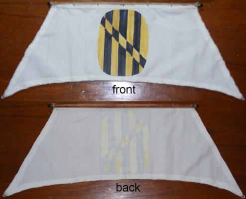
I use a fine permanent marker on my sails, like .001, and draw both sides, a little bit off to represent the width of the seam. Test it on some scrap before you commit. There is a method where a portion of the cloth, outside the area of the sail, is colored in some fashion, and single threads are pulled through the weave to move the colored portion into the area of the sail. While the effect is impressive, it wastes an amount of cloth equal to the area of each sail. An alternate method is to run a bead of fabric glue above and parallel to the head and pull the threads at the seam locations down while bunching the sail up towards the head. Color these threads and unbunch the sail pulling the threads back in. This gives the same effect without the waste and in small scales is quite impressive. Sewing seam lines is common, but in-my-opinion, nearly always looks out of scale, and typically causes unrealistic puckers in the cloth. It's difficult and tedious to do well. On large scale models, like 1:16th, 1:6th, typically models of small craft; before it's cut, the cloth is Z folded at each seam and sewn. This is as close to a seam as you can get without it actually being a seam. At smaller scales, even 1:24th, it's near impossible for this method to appear in scale to the model. Whatever method you opt for, success will depend on the quality of the cloth used and your patience. Most cloth used is hopelessly out of scale to the model they're made for - another reason I build in large scales.
-
You're not building an accurate model of an actual boat, but a sort of fantasy boat. I don't think this is much of an issue, especially not structurally. The bottom line is you. It's your model, what do you want? If thine wale offend thee, pluck it off.
-
I can't tell from the photos what you mean.
-
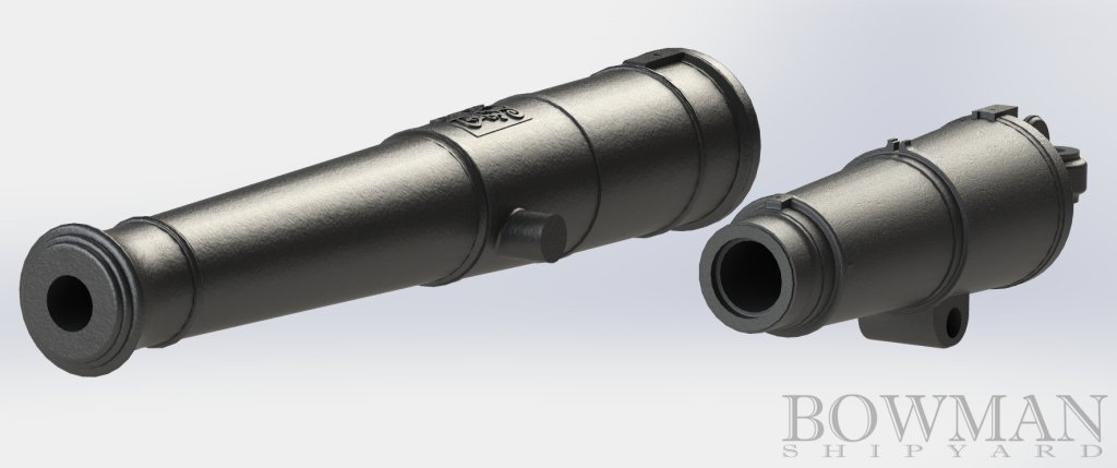
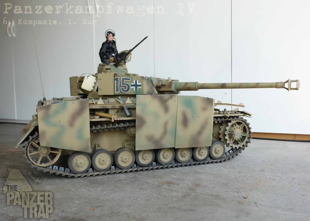
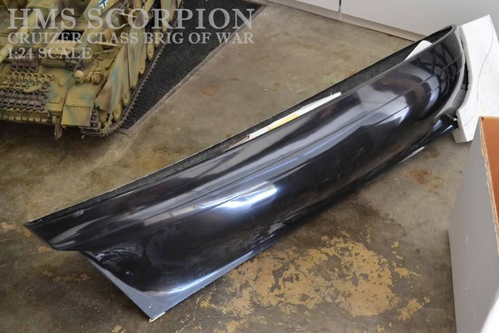
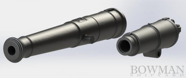
A fellow on the left coast, Tom Bowman, got wind of my Macedonian project and contacted me a while back. He's another big Hornblower fan and a fan of the British frigate as I am. He's also a builder of large scale working tanks from scratch - armored fighting vehicles that operate and are beautifully detailed. I shared my Mac plans with him and he plans to build another Lively class boat, the Spartan for RC, but in 1:24 scale. Until then he's purchased and is detailing one of SC&H's Crusier class kits, also in 1:24 so Spartan will have a play-mate. How the kit hull comes; note the tank pictured above in the upper left for scale Where it is as of this posting; it's already becoming a beautiful model. Since Tom's modeling the guns for Spartan in SolidWorks to be 3D printed and used as masters to cast the rest, he's actually doing a set of masters in 1:36 for me to produce Macedonian's batter from; Blomefield pattern 9 pounders, 18 pounders, and 32 pounder Carronades. These are gonna be great


- 97 replies
-
- 3
-
-
- macedonian
- frigate
- (and 2 more)
-
Thickness sanders.....Byrnes vs Micro Mart
JerryTodd replied to bigcreekdad's topic in Modeling tools and Workshop Equipment
You might add something like this to the running -
Actually, this one was closer to turning a roll of tape into a ship Thank you
-
Black iron bands may not refer to color, but to the use of black iron. Wouldings would need to be tarred
-
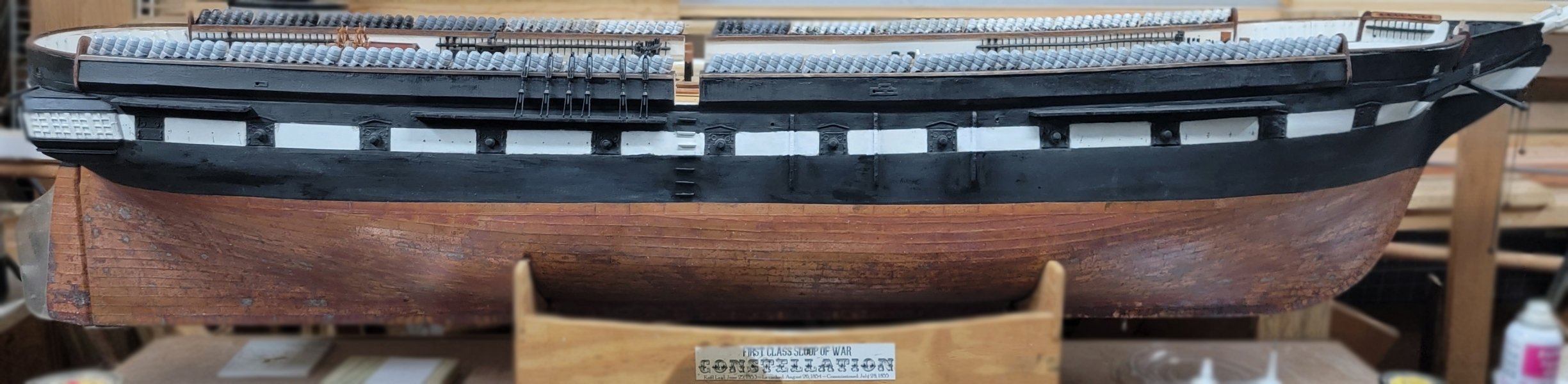
I wonder how many captains would invest the time to paint the mast bands a different color to serve no purpose other than it looks nice, especially in war time? In peace time, I can easily see a captain keeping his crew from being idle with such chores. In the 1860's Constellation's captain regularly had the copper scrubbed, paint above and below, and rigging rerove. He even had the gun stripe painted out, and a month later repainted back on. While that was wartime, Constellation was in the Mediterranean cruising between Italy and the Levant "showing the flag" and not much more - there was a LOT of idle time.
- 601 replies
-
- 1
-
-
- constitution
- revell
- (and 1 more)
-
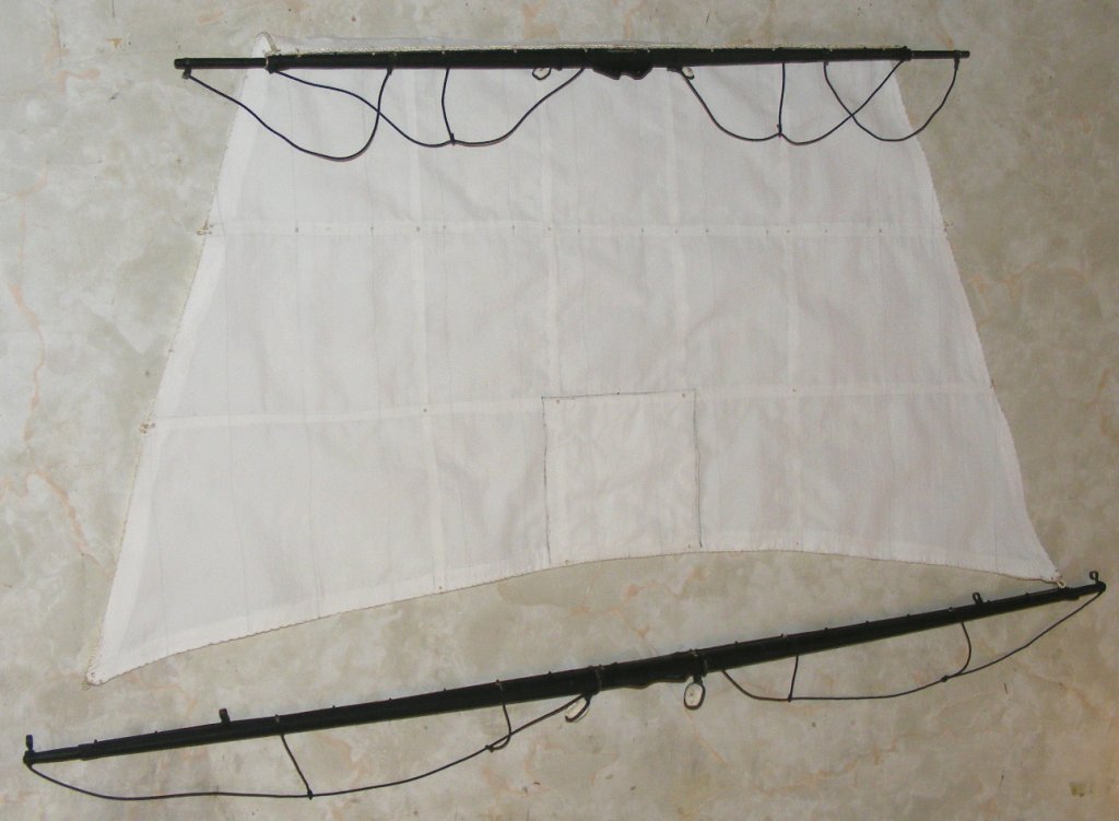
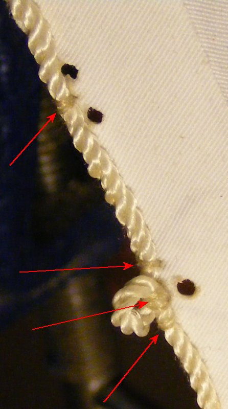
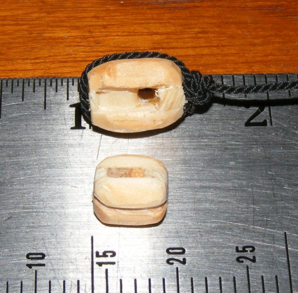
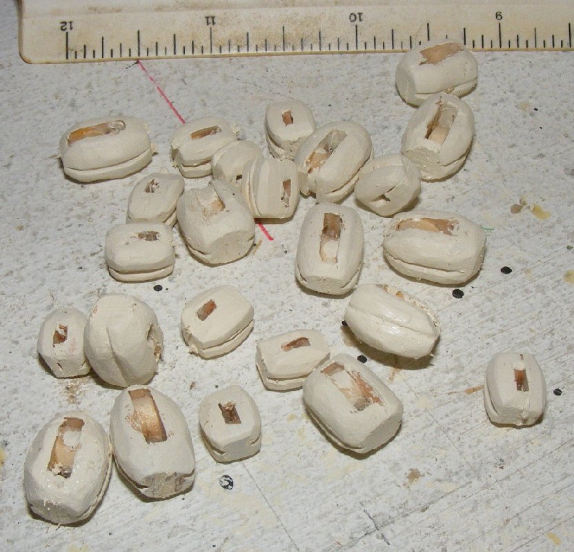
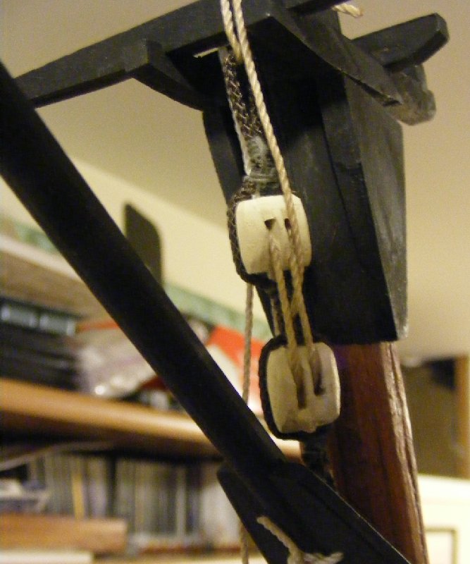
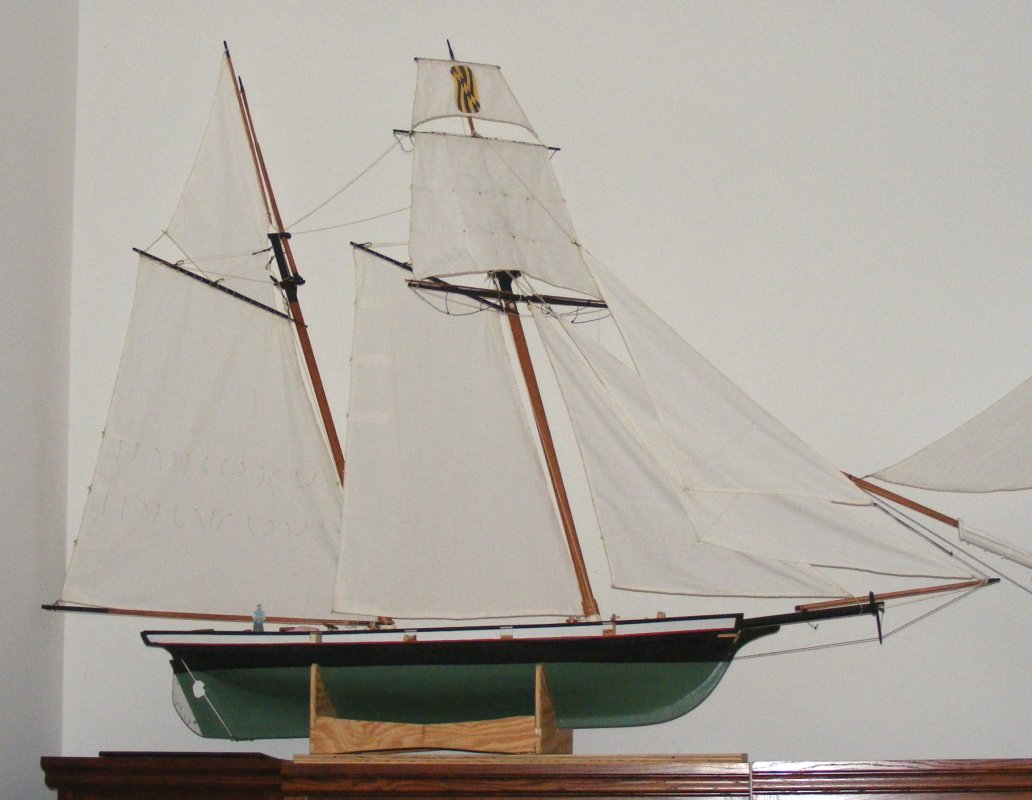
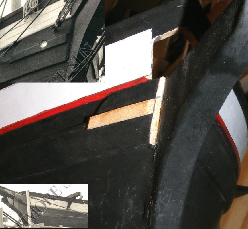
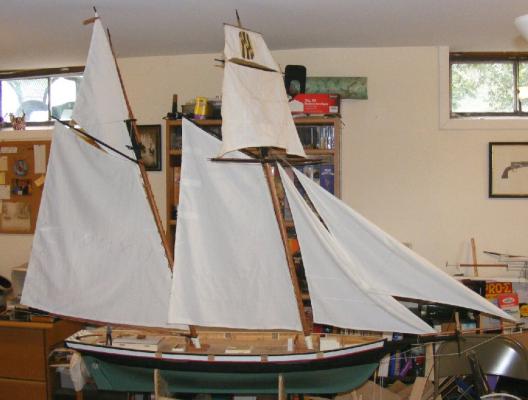
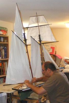
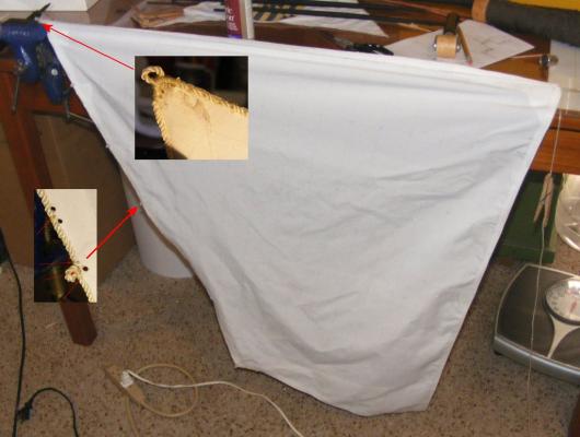
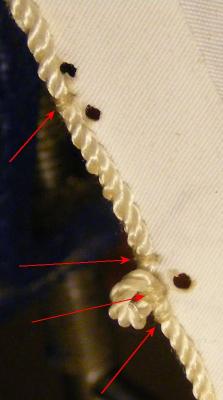
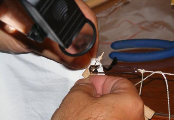
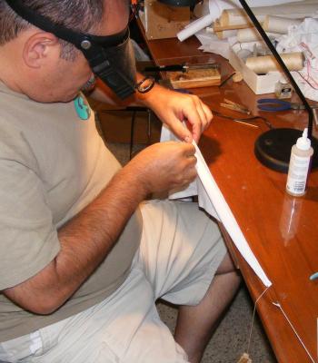
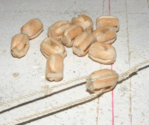
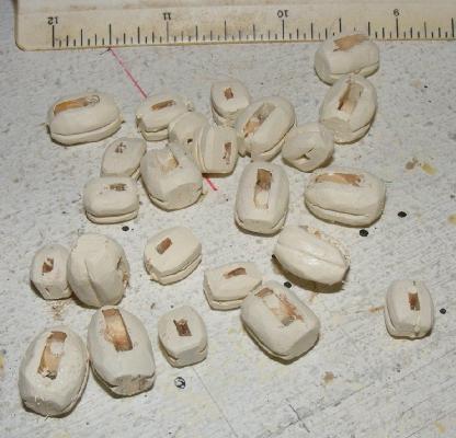
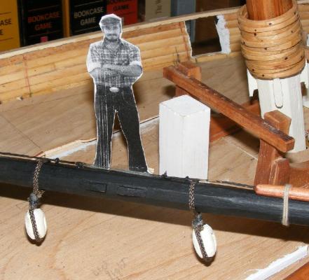
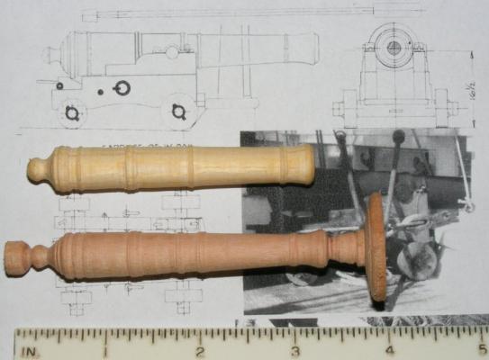
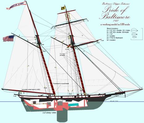
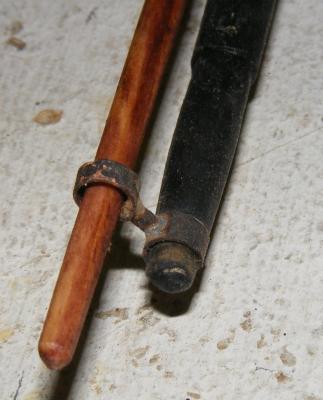
I was asked to bring the model to the Fell's Point Maritime Museum in Baltimore on July 22nd, 2012, for a one day display to commemorate the anniversary of the first 7 letter of marque vessels to sail out of Fell's Point for the War of 1812. It wasn't possible for me to fully complete the model in time, or even get it sailable, but I resolved to do as much as I could to make her presentable for display. The Pride of Baltimore II would be there, and I had sailed on Pride with her captain, Jon Miles, ie: someone intimately familiar with the boat I was modeling would see it, but hey, no pressure. In preparation though, I bolt-roped all the sails, worked out a chart of what rigging blocks she would need, and began making them. The sails are roped with a three-stranded nylon cord. The bolt rope is glued to the sail with fabric glue as well as sewn in an abbreviated version of the way real ones are sewn on. A bolt rope isn't sewn the the edge of a sail, but rather to one side of it right at the edge. Each stitch passes between two strands of the line, through the third, and into the sail, where it takes a turn back around and repeats in the next strand. Each turn is in the direction of the lay of the line sew the stitching disappears into the lay of the bolt rope. In stead of every strand, I stitched through every three or four strands. The stitching is somewhat visible at this scale, especially on the "back-side" of the sail from the bolt rope, but the glue makes up for the reduced structure. Eyes, cringles, garnets, etc, along the edge of the sail were made with the bolt rope. grommets in the sail are burned with the pointed tip of a soldiering iron. This is a nice feature of using Supplex, holes can be made for reef-points, for example, that are heat sealed and require no further reenforcing. Eyes are formed around a round toothpick to maintain constant size and keep the from closing while sewing's in progress. Grommets are burned in near each eye for and the bolt rope is seized on either side, just as a real sail is constructed. Well, this IS a real sail, just a small one. By-the-way, did I mention I used to work at Ulmer Kolius sail makers near Annapolis? I didn't usually sew on bolt ropes there, that I learned working on boats such as Pride; at Ulmer I did things like putting ducks on Flashers (a genoa/spinnaker hybrid). The yards got foot-ropes and I made some unsheaved blocks to cover for this display. The sails were attached to their spars, the main and fores'l to the mast hoops, Halyards rove, and bit by but, Pride was dressed. I was ready. I even cobbled together a slide show of the models construction and loaded it onto an e-frame, and made up some hand-outs with specs on the model and the real Pride. Unfortunately, the events schedule was changed to a day I would be out of town for something else - so Pride didn't get publicly displayed. Later, I made and attached fairleads to the fore tops'l for the bunt-lines which I made from a bamboo chopstick. I found the new information on the pump heads mentioned previously. And noted a sort of rub rail under the hawse pipes of the original boat and a difference in how the wale finished at the bow. I took a shot at turning a gun barrel, one in pine, one in cherry - neither of which I'm satisfied with. The carriage was better, but I had to draw scaled plans as Gilmer's drawings of the guns were a bit cartoonish. The model's been moved to my new residence, as I move out of my house. With no consistent income since being fired in January 2012, after 18 years, the house is being foreclosed on. For the moment, Pride sits on top of a cabinet in the living room waiting for the new shop to come online.


- 79 replies
-
- 11
-
-
- pride of baltimore
- privateer
- (and 3 more)
-
Wow, is it that time already? Thank you
-
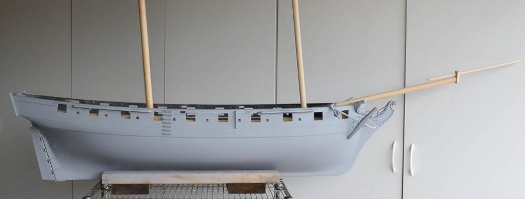
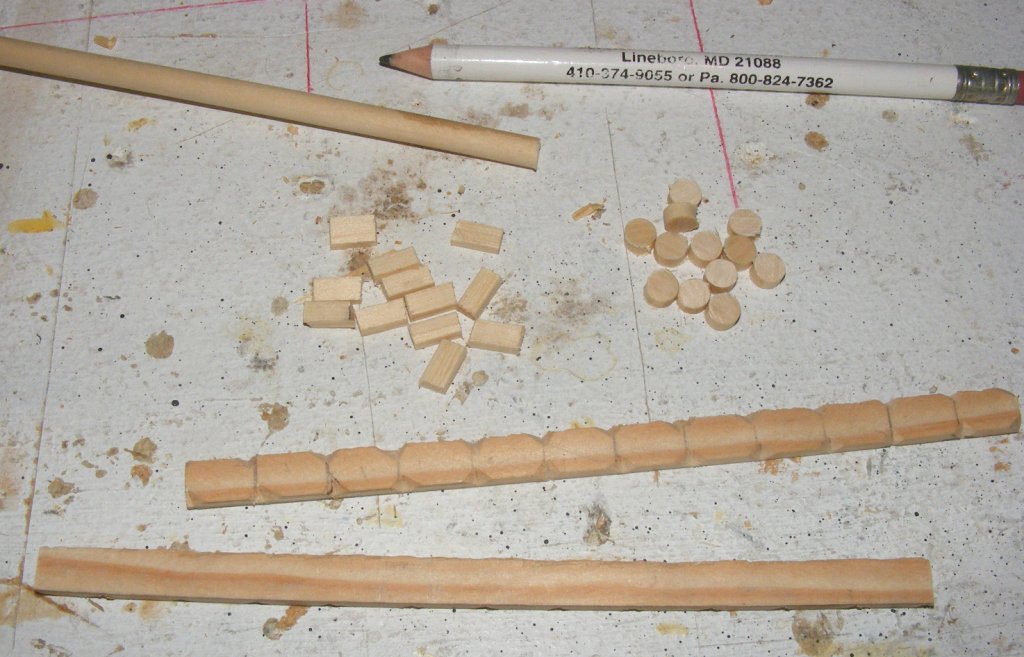
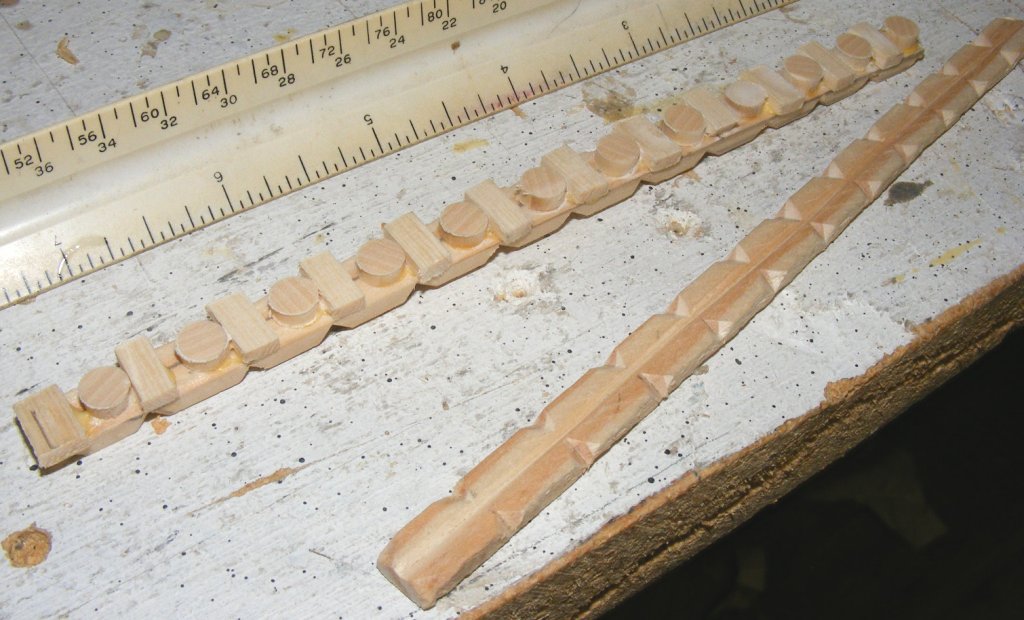
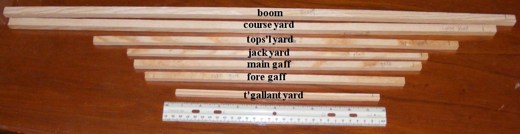
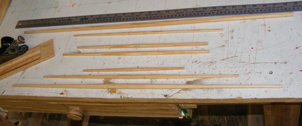
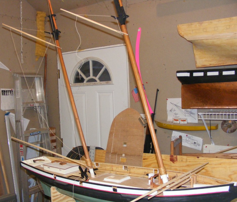
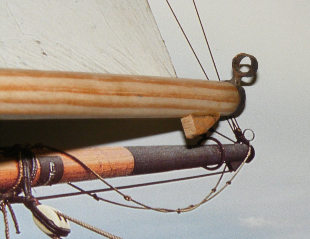
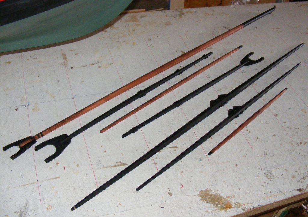
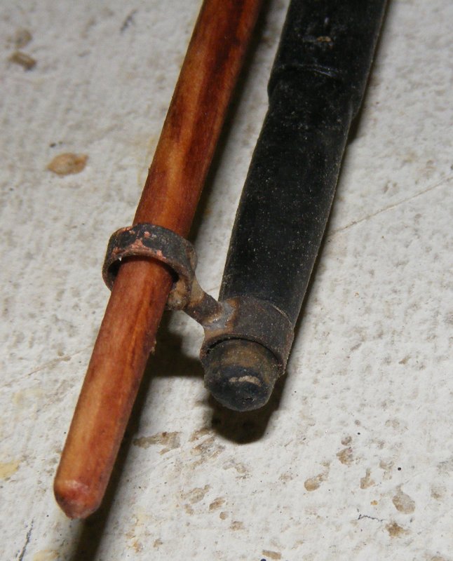
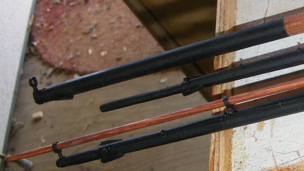
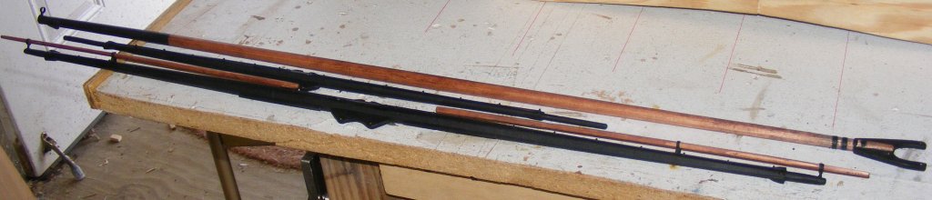
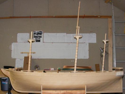
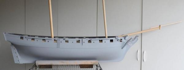
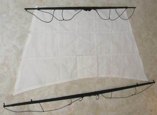
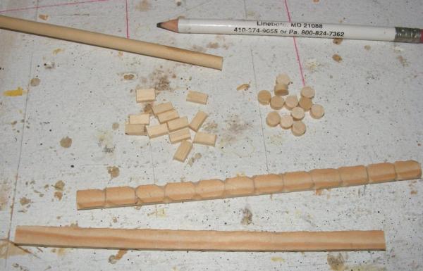
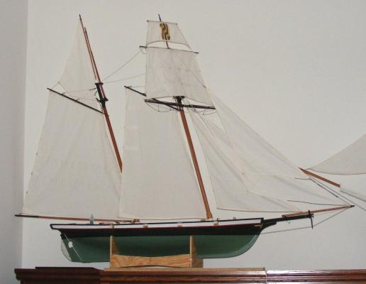
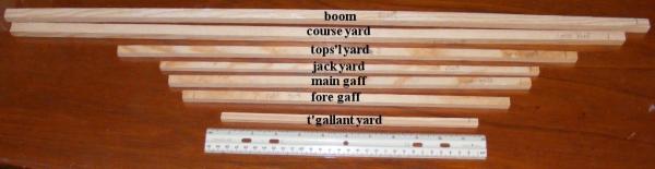
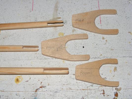
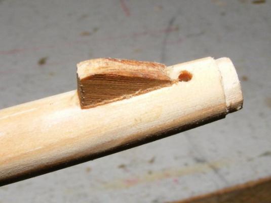
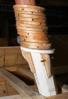
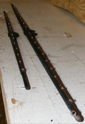
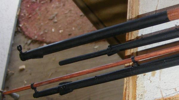
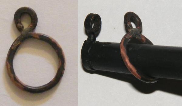
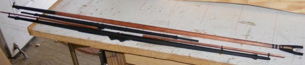
Spars All the spars were made of white pine, since it's been working so well so far. Rough cut to size, square stock was made 8-sided, etc, etc, to round. Gaffs and boom were fitted with jaws made from aircraft plywood and tried for size. The boom has a shoulder cut in the end for the ring-tail iron and a bolster that keeps the mains'l clew out-haul held off the boom. The main mast was fitted with a saddle and knees for the boom to rest on, after the mast's hoops were loaded on. All the spars got stain and paint, and all the brass was blackened and painted. The coarse yard got stuns'l boom irons, stuns'l booms, and jack stays. Cleats and holes for sheets and the like... and a clew iron for the main boom The yards and boom


- 79 replies
-
- 8
-
-
- pride of baltimore
- privateer
- (and 3 more)
-
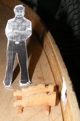
Bait tub?