MORE HANDBOOKS ARE ON THEIR WAY! We will let you know when they get here.
×

JerryTodd
-
Posts
873 -
Joined
-
Last visited
Content Type
Profiles
Forums
Gallery
Events
Everything posted by JerryTodd
-
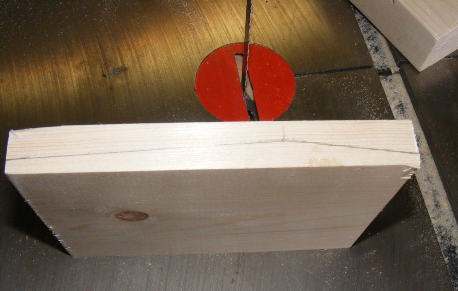
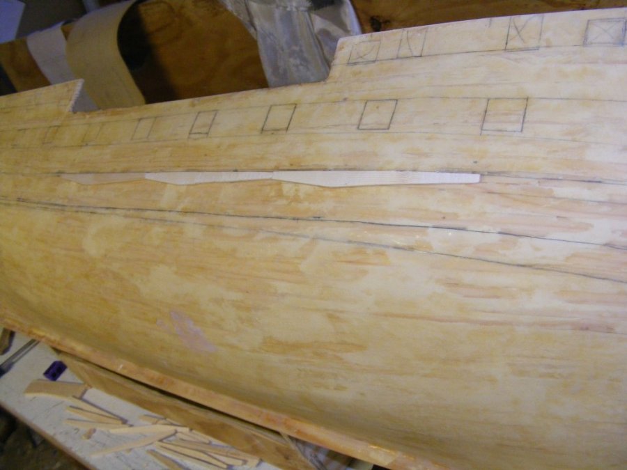
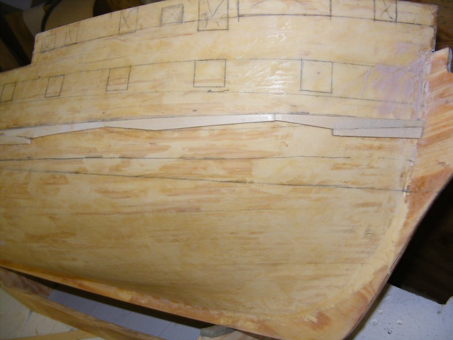
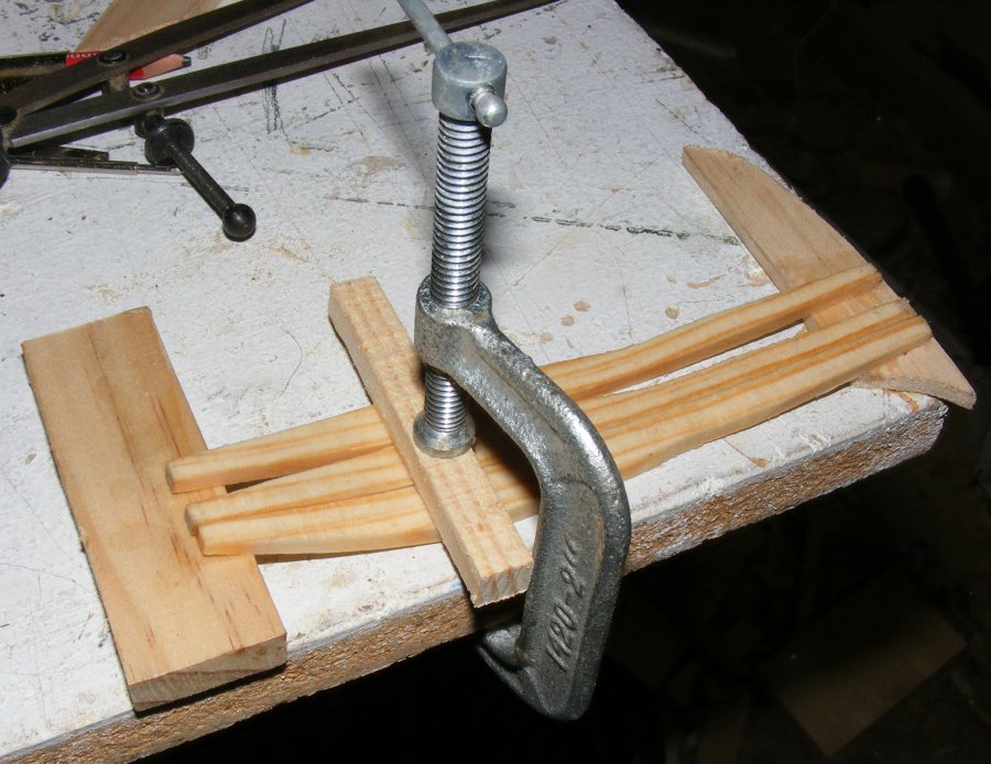
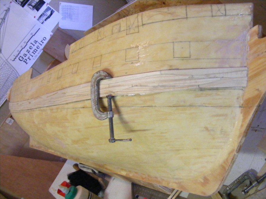
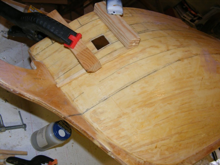
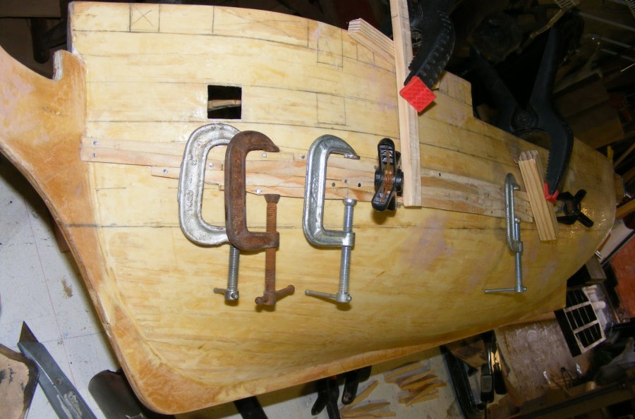
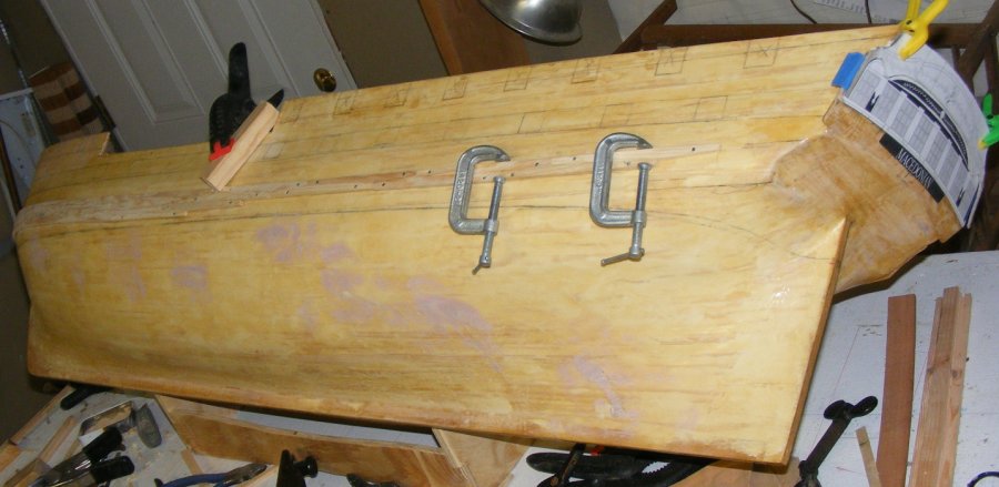
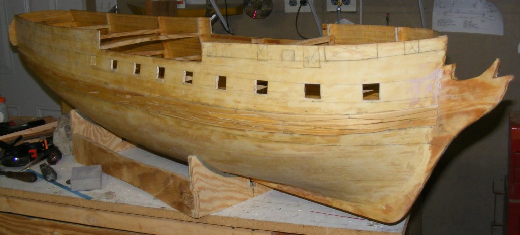
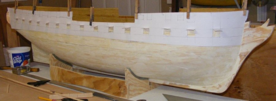
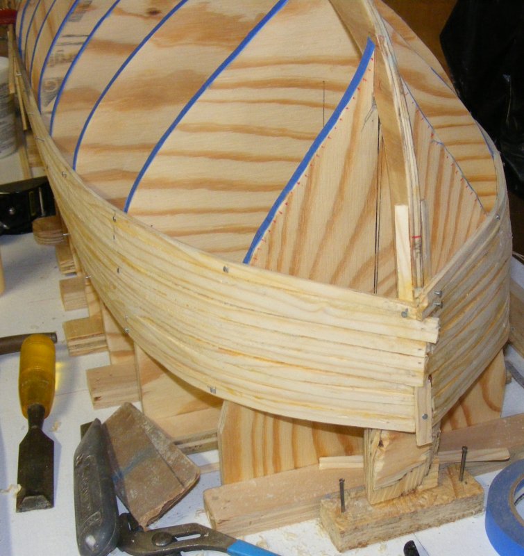
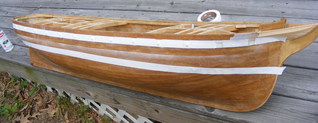
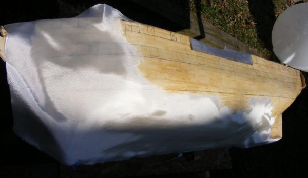
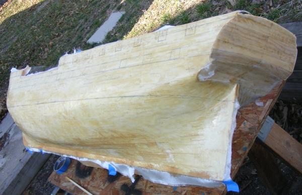
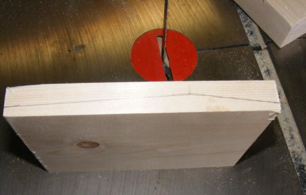
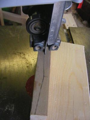
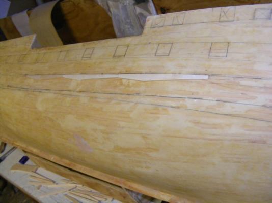
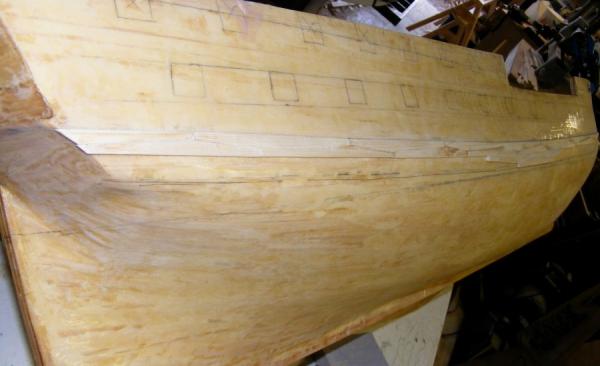
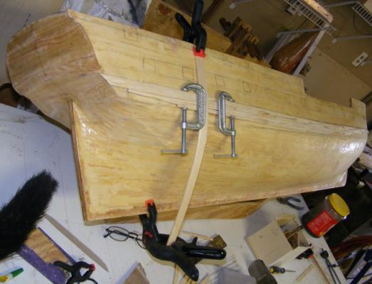
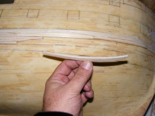
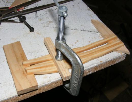
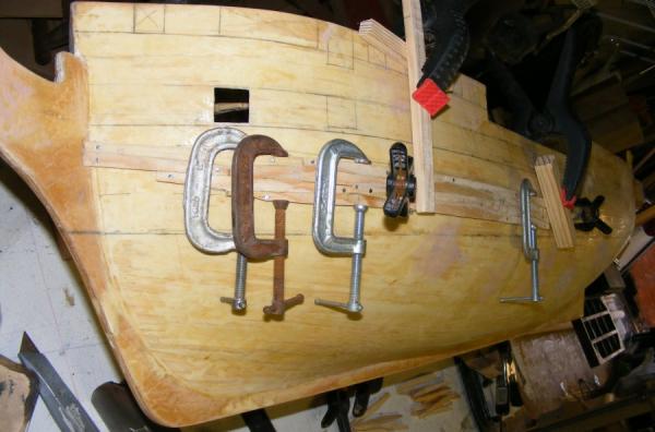
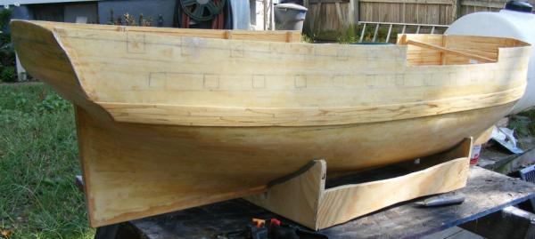
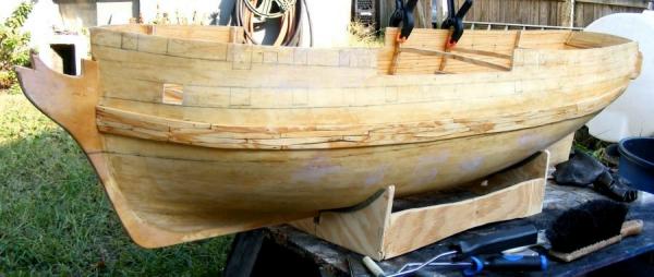
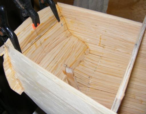
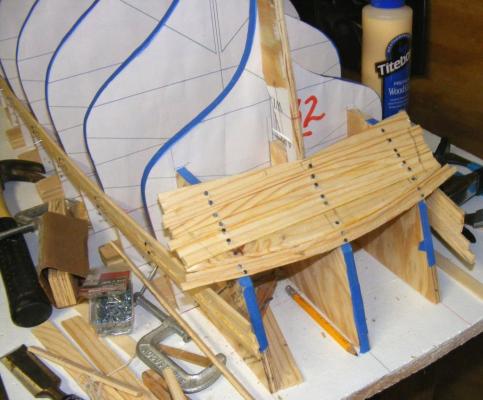
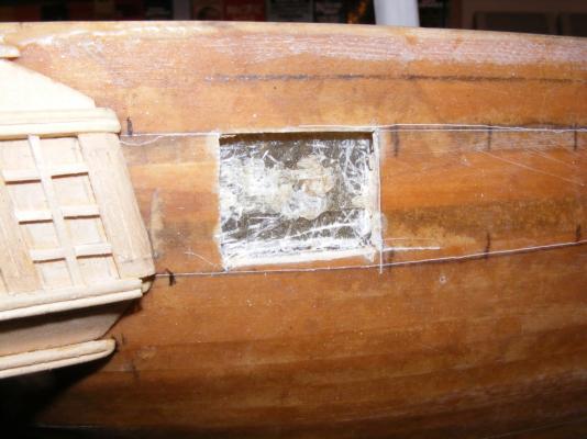
 Fiberglass With frames set in and the hull's shape stable, it was time to glass the outside. I started with the transom Then the portside Once that had set-up, it was on to the starboard side There, that wasn't so bad Excess resin went into the bilges and on the lower frames. After the glass set-up and was sanded, there were some blisters where the glass didn't lay and bond to the hull, these came off while sanding and were filled with auto-body putty. More sanding and another coat of resin brushed on, then sanding again. Some clean up and degreasing and it's... Wale Ho! On this model the wale isn't the structural member it is on a real ship, but I did want it done in an anchor-stock pattern as it would be visible on close inspection. I started by cutting a block of white pine, as used for the rest of the planking, to the offset anchor-stock shape, then slicing off 1/8" thick planks. I started on the starboard side by marking the positions of each plank on the hull from the bow aft, and actually started gluing them on amidships. I used CA to attach them to the hull, and Titebond III to glue them to each other. Clamping them to the hull took some thinking at places, as did clamping them to each other without lifting them off the hull. At the bow the pieces needed to be precurved, so the SBJ (Sophisticated Bending Jig) was employed. The pieces were wet, clamped in the jig, and left overnight. It took a little over a week, but the starboard wale was done. Now to the port side! I took a slightly different approach this time. Clamping the pieces to the hull was quite tedious, so I used the nails I used to hold the planking with during construction to hold the pieces onto the hull here. This made things go much quicker and smoother. Before starting though, I cut out a gunport just for fun. I was afraid the hull would flex with the ports cut out, but I need them cut before I frame up the hull thickness behind them, because that framing sets into the gunport opening a bit. Actually, the planking is set back creating a rabbet for the lid to close against. My friend Mark was building a crabbing skiff at my place, and while he had the epoxy out, I stole a bit to give the wales a couple of coats I then started carefully cutting out each gunport opening. Once all the gun ports are cut out along the gun deck, the internal framing will go in around each one, making the hull the right thickness as seen through the gunports. The focs'le and quarterdeck ports will be cut after they're framed and the external moldings have been installed.


- 97 replies
-
- 17
-

-
- macedonian
- frigate
- (and 2 more)
-
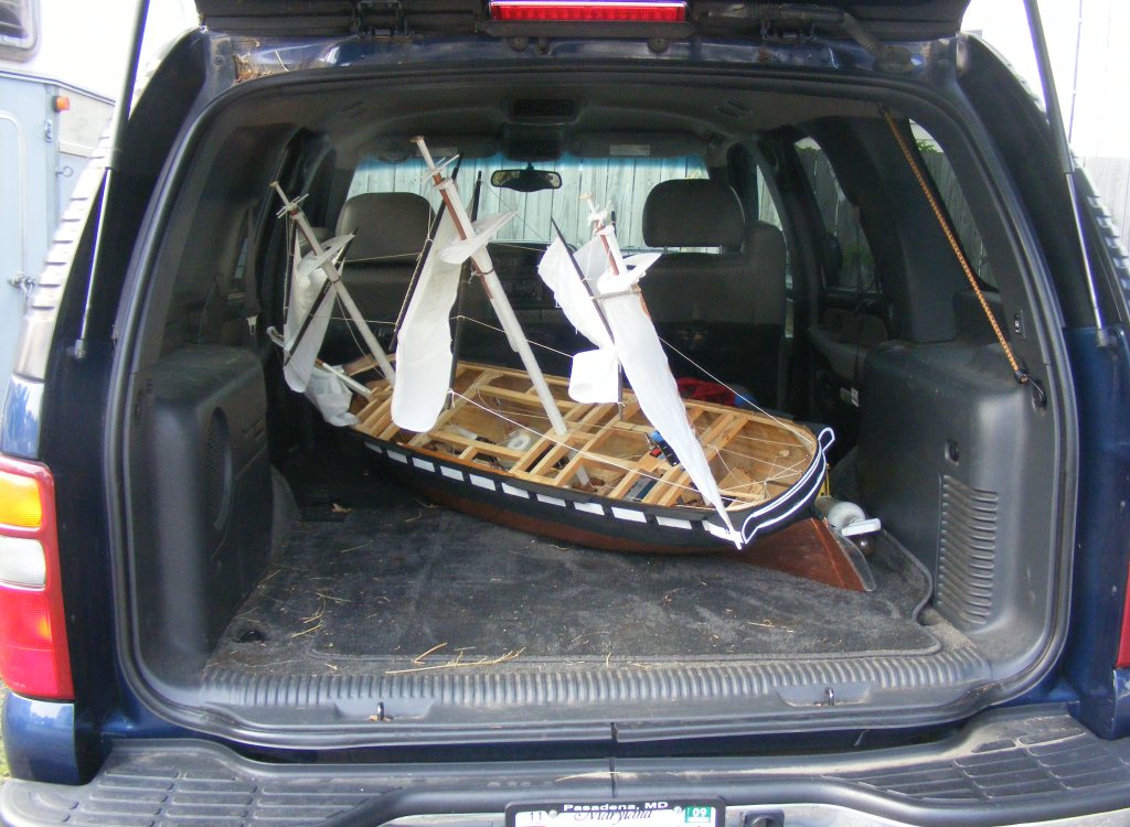
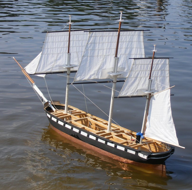
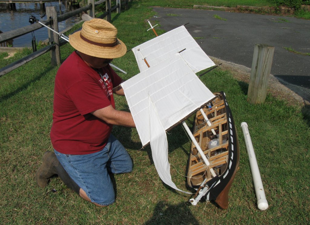
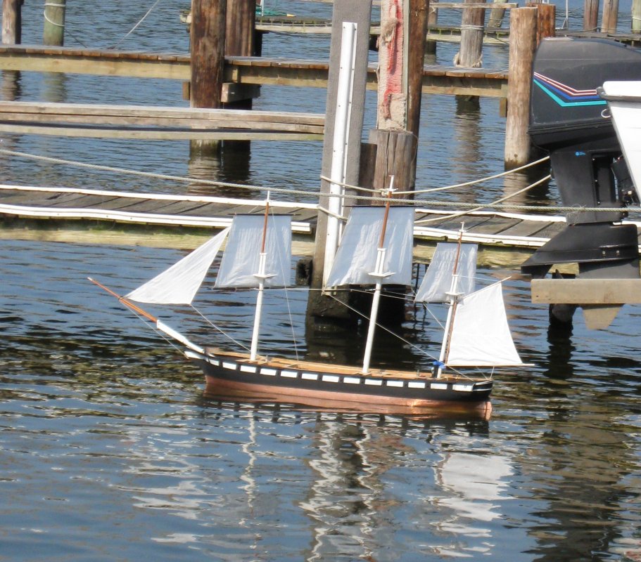
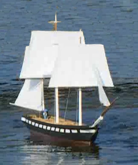
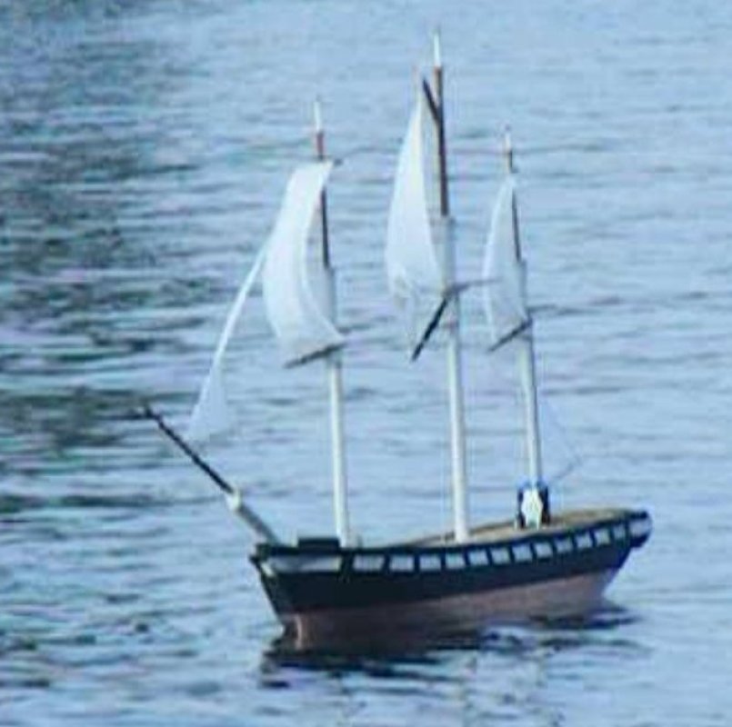
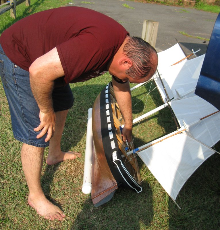
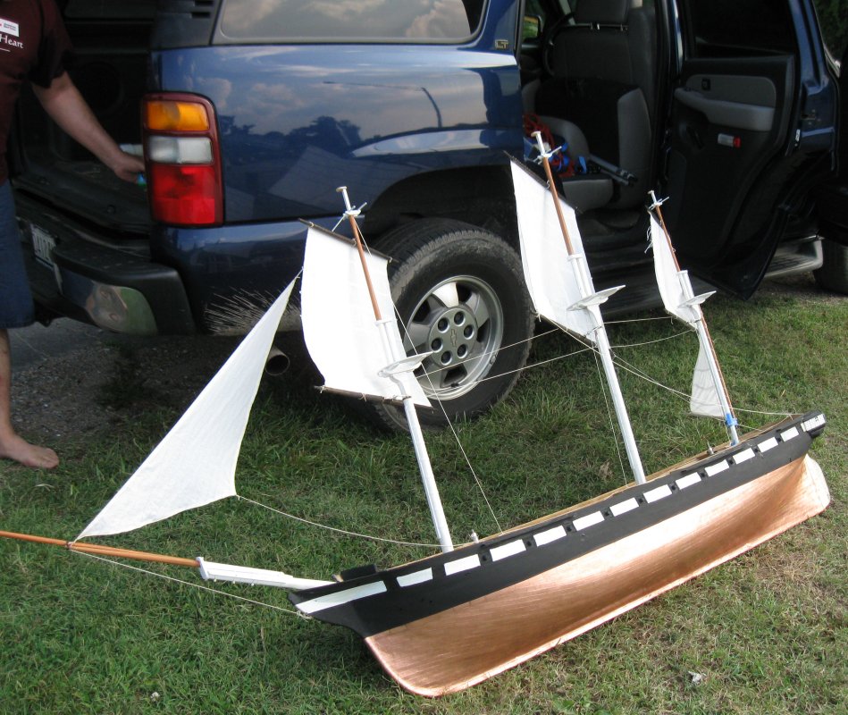
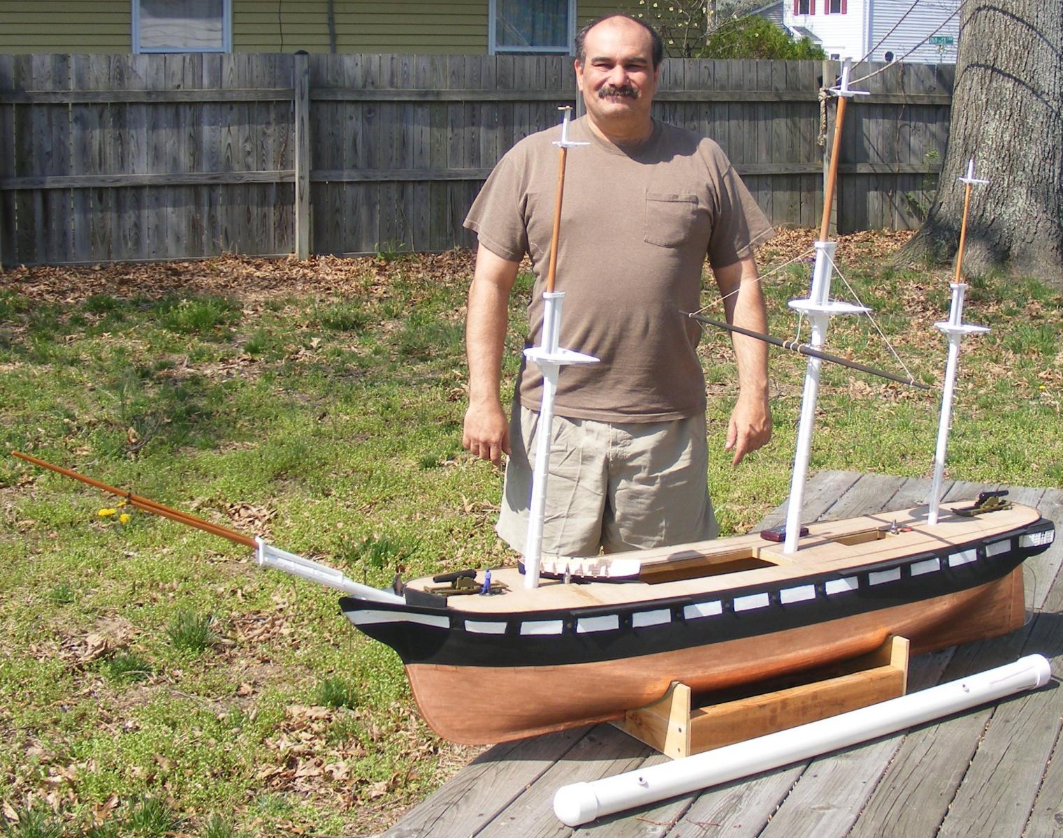
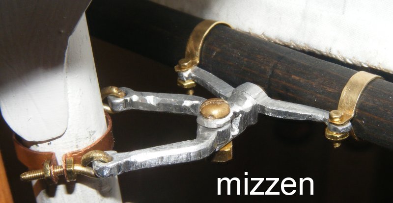
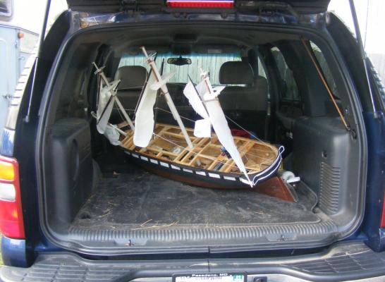
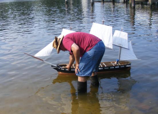
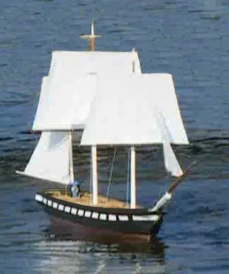
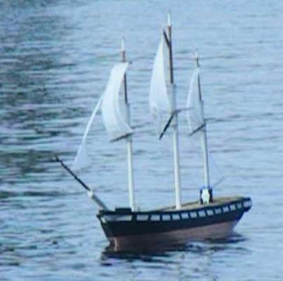
Lines were rigged connected course yard to course yard the same distance from the center-line on each side of the model. Lines that would serve as braces ran from the main course yard ends to the quarters of the hull and to the springs on the post, and then to the winch. This way the winch would swing the main course yard and the connecting lines would move the fore and mizzen yards at the same time. This is not how the model will eventually be rigged for running, but it would do for a test sail. Video of Brace Testing The fids were pulled, the topmasts lowered, and batteries put on the chargers. The next day, July 10th, 2011, the model and it's equipment and accessories, were stuffed into the Tahoe. I took the model, and my lady who was to be the official videographer, supplied with camera and tripod, a quarter mile down the road to Sloop's Cove on Stoney Creek, where the neighborhood has a public pier and water access - such as it is. At the site I raised the rig, bolted on the ballast, and tested the systems. Getting her into the water, I placed the sandwich bags full of lead bird shot left over from the ballast torpedo and weighing about 12 pounds, into the hull and moved them about to trim her. There still wasn't enough weight to get her down the the LWL and she stood about 1-1/2 inches high in the water. Then off she sailed. And some of the video... It wasn't an unsuccessful day, but it was a bit disappointing. The winds were too light and variable, and in the creek there, they swirled and eddied about. The model never really got more than a few feet of any real sailing. When it would puff strong for a bit, she handled it fine, then it would shift and catch her aback. She also handled the occasional wakes from passing boats quite well. Then, about an hour in, the battery died. I later found it had failed completely and needed to be replaced. The model was near the middle of the 100 yard wide creek and headed toward a boat dock about 50 feet away from me. I went into the water and swam over to meet her. She gently bumped her forestay against the dock and stayed there till I got to her. I'm not much of a swimmer and quickly wished I had brought one of my floatation vests to make the job easier - but it was in the 90's and the water felt pretty good. Next time I'll have some form of chase boat; a kayak, inflatable, or preferably a pram I'll build. Note: That thing at the base of the mizzen is an on-board camera. It took some incredibly boring video. If I can get some editing software that will let me put it up split-screen fashion in sync with the other video, I'll post it somewhere. Video of the Recovery or how the big bald ape rescued the model ship from certain doom without himself drowning. Then it was out of the water, off with the ballast, down with the rig, and into the truck.


- 553 replies
-
- 8
-
-
- sloop of war
- constellation
- (and 3 more)
-
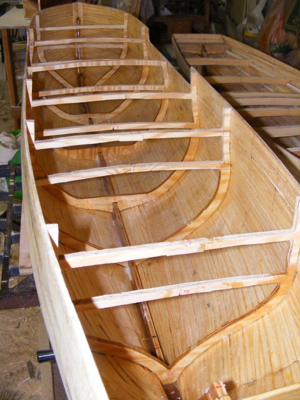
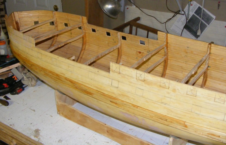
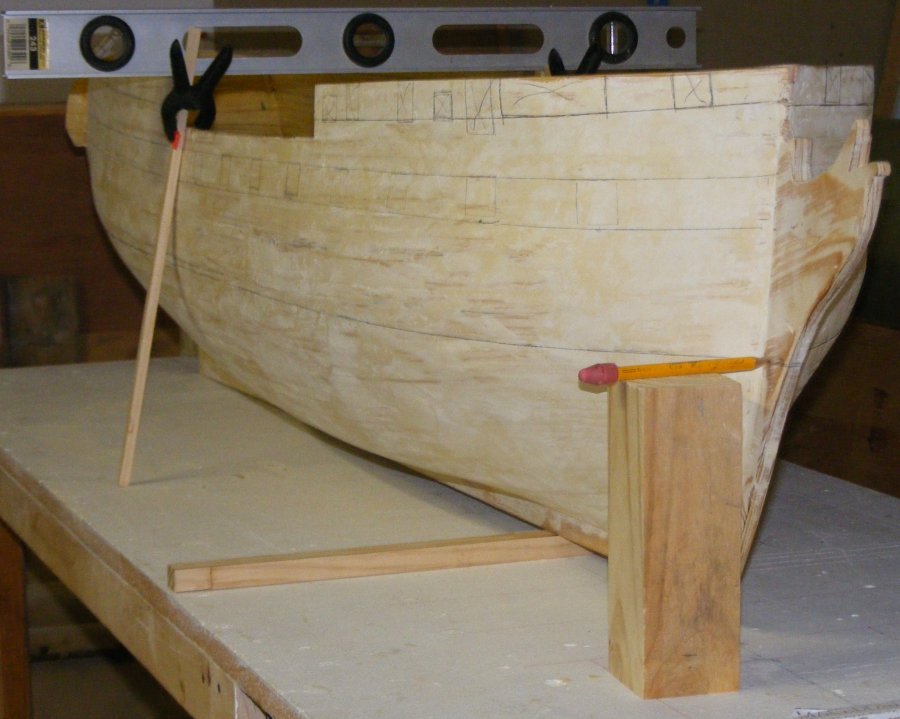
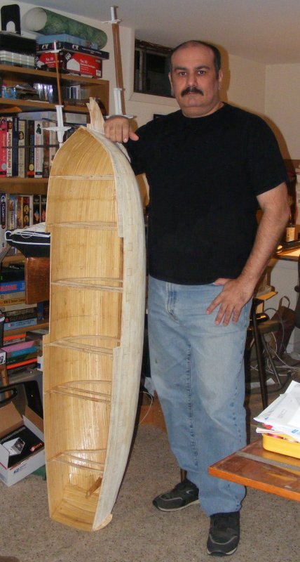
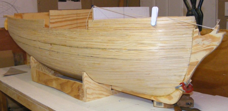
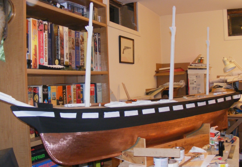
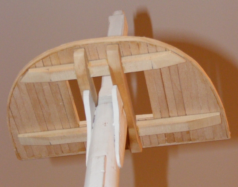
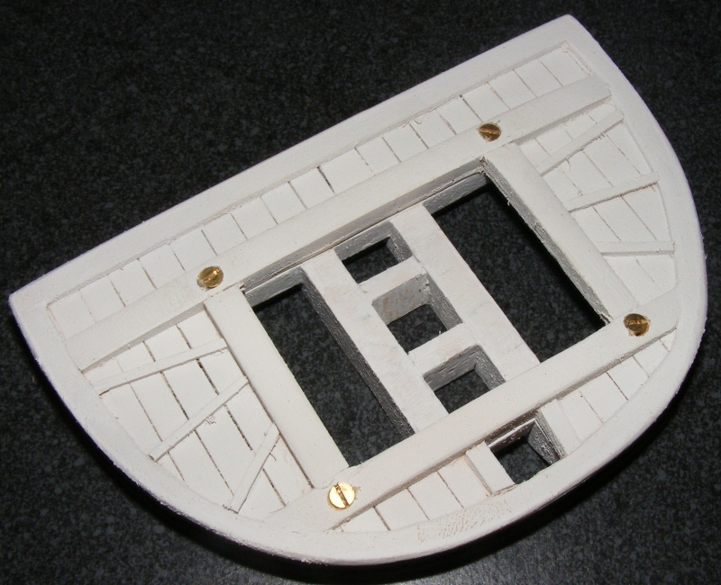
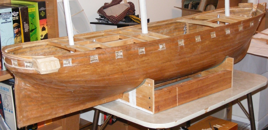
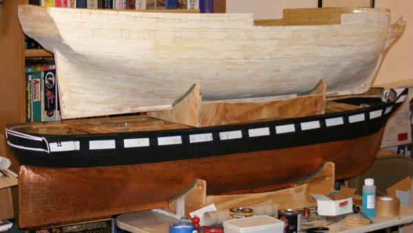
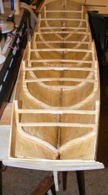
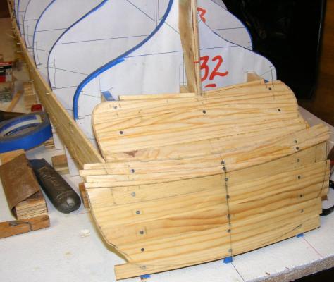
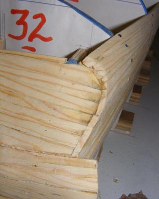
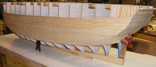
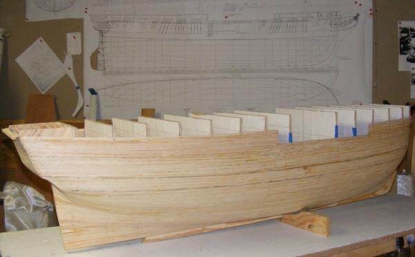
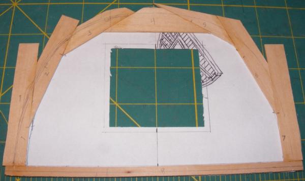
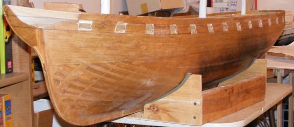
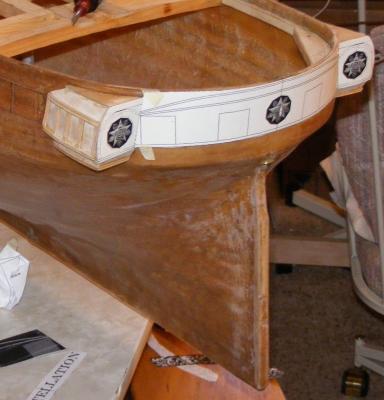
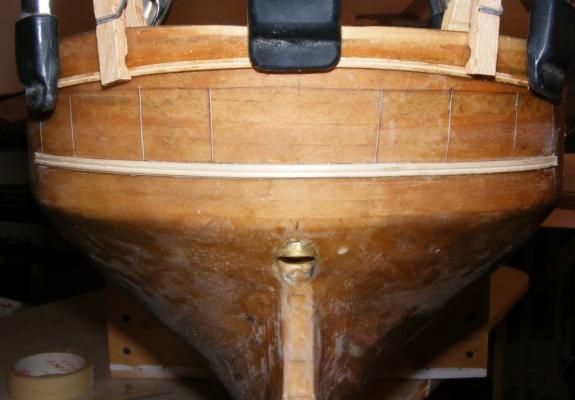
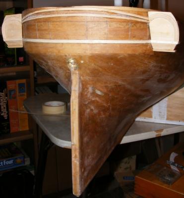
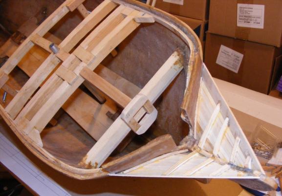
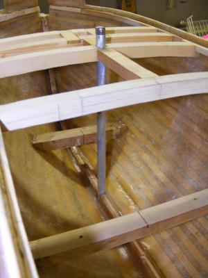
A brace was installed under the quarterdeck level to hold the curve in the transom. On Christmas day I found that St Nick hadn't sanded and resined the interior of the hull as I had hoped, so it fell to me to do it. It was sanded, cleaned, and given a couple of coats of poly resin. Excess resin was poured into the bilges to fill any nooks and crannies so small parts, dirt, and water would have no where to hide. A full size paper pattern of the gun ports, moldings, and other such hull details was made. Care was taken to use the plan to make sure items that were on surfaces curved away on the profile were in their proper place, such as the bridle ports. As I was cutting out the gunports on the pattern I realized I had formed a gunport lid; I couldn't resist doing them all that way. Macedonian is a little shorter than Constellation. Constellation compares in length to the frigate United States so you get a little bit of an idea of the size relation between Macedonian and United States. The build table was leveled, then the hull placed on it level port and starboard, and with the waterline marks fore-n-aft at the same height from the table. A pencil resting on a block of wood cut to the right length was used to mark the waterline. Approximately every-other station used to make the hull was cut down to scale framing dimensions and reinstalled into the hull. The reason for this is because the complex shape of the hull with it's tumble-home and counter tumble-home, was trying to flatten out. These frames are glued into the hull with epoxy mixed with wood dust.. The rest of the interior from the gun deck up, will get framing and ceiling planking to make the hull the proper thickness. Some idea of the size of the thing - 5 foot from tip-to-tip. Next: Fiberglass!


- 97 replies
-
- 16
-
-
- macedonian
- frigate
- (and 2 more)
-
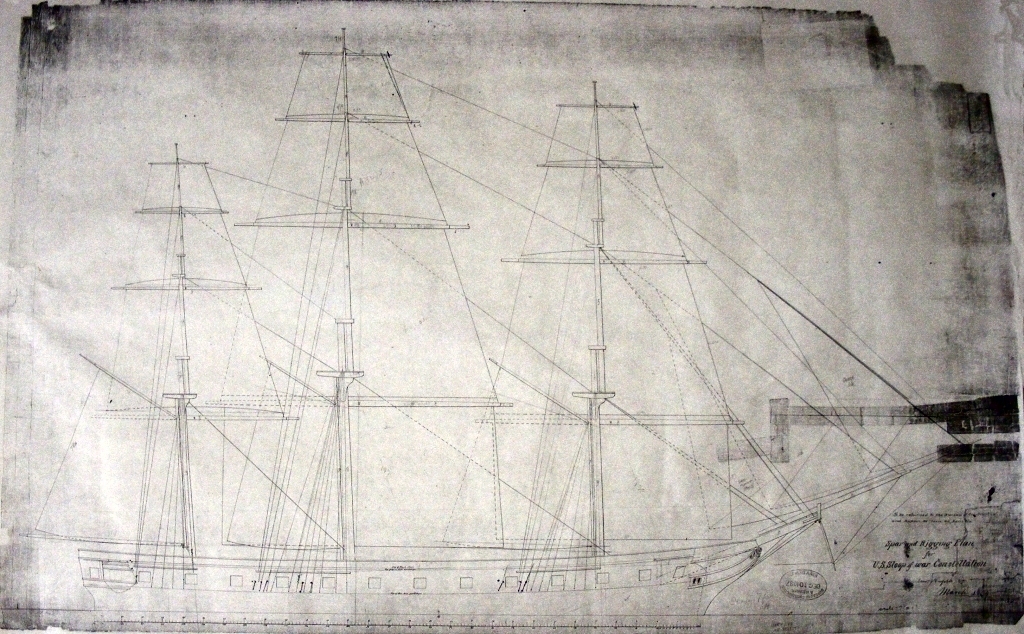
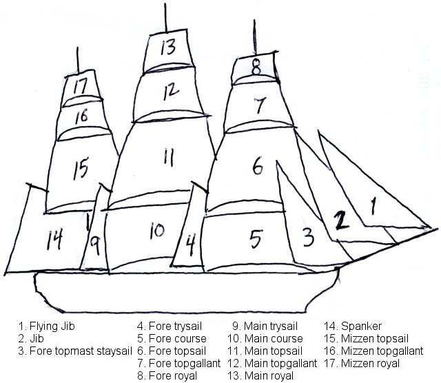
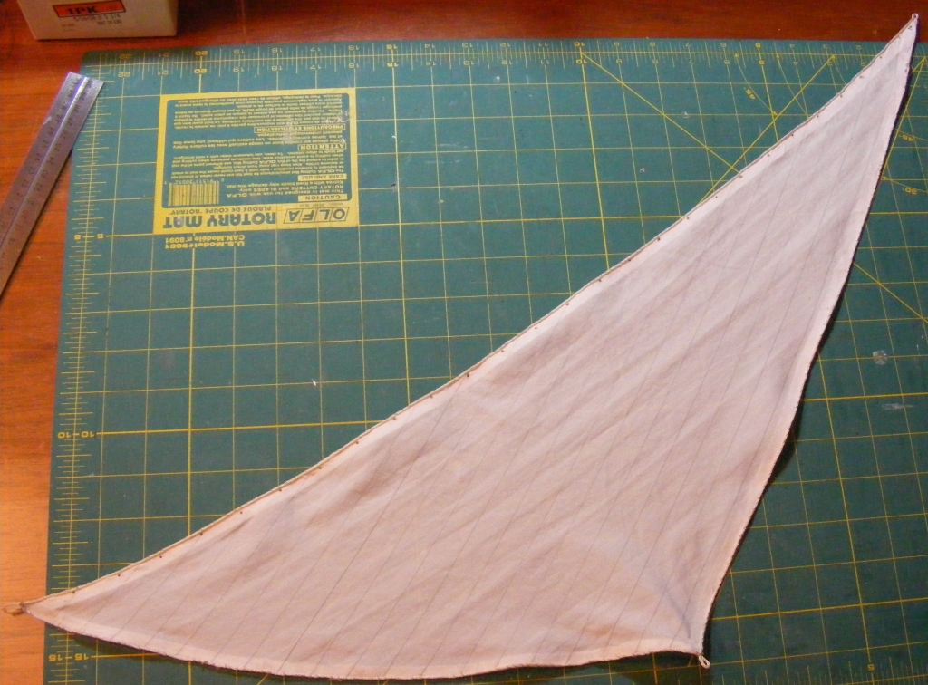
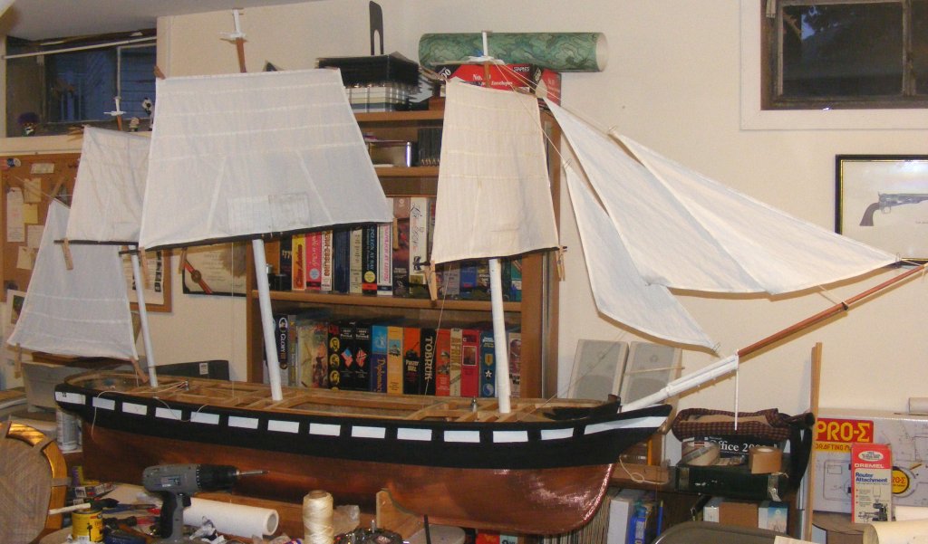
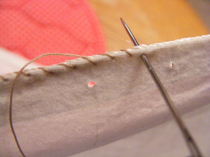
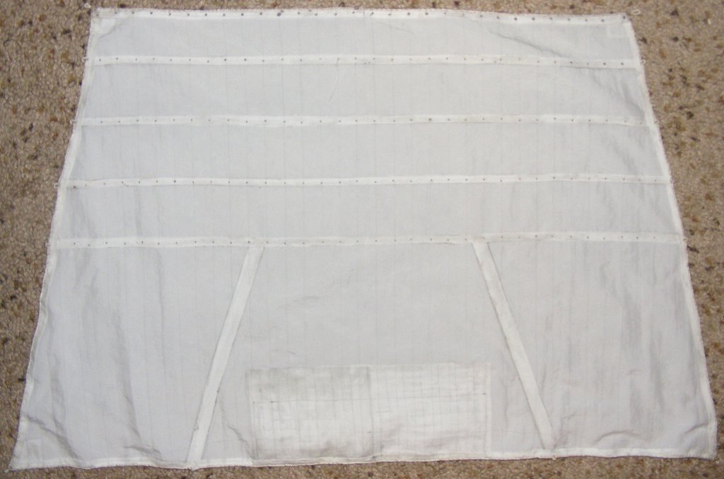
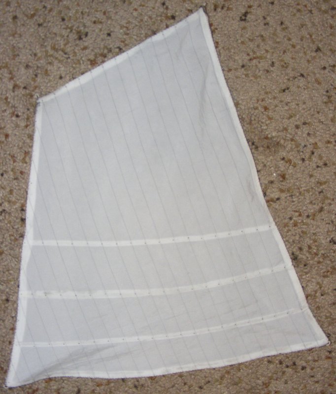
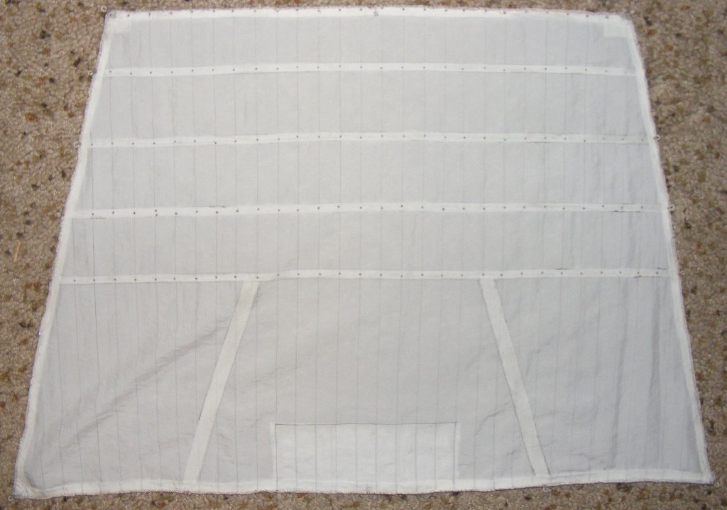
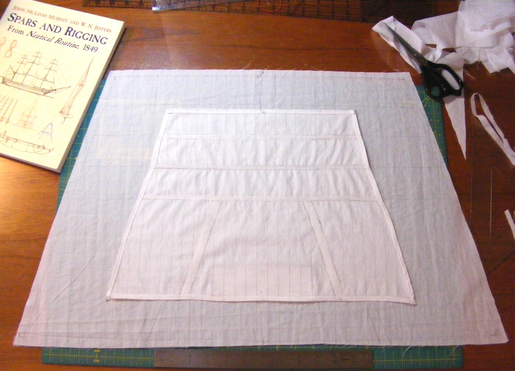
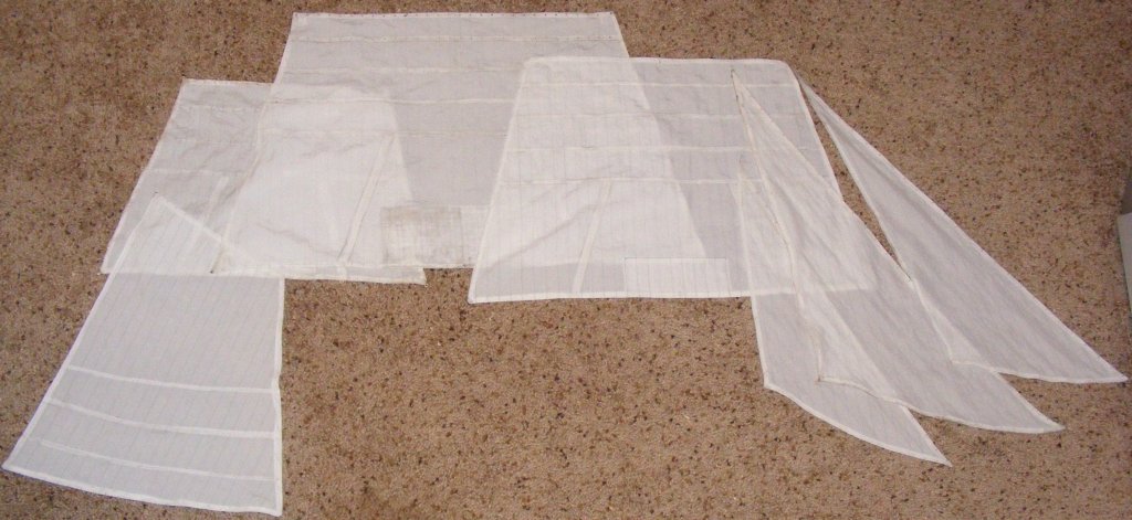
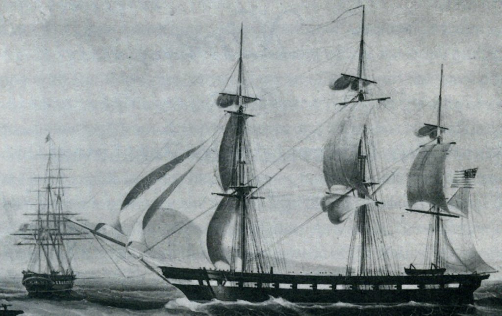
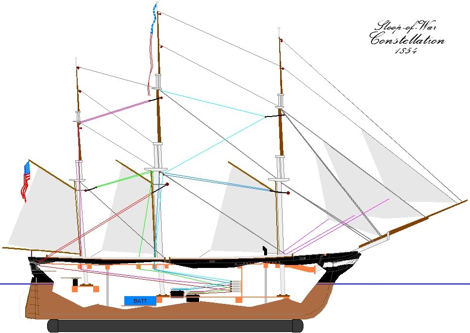
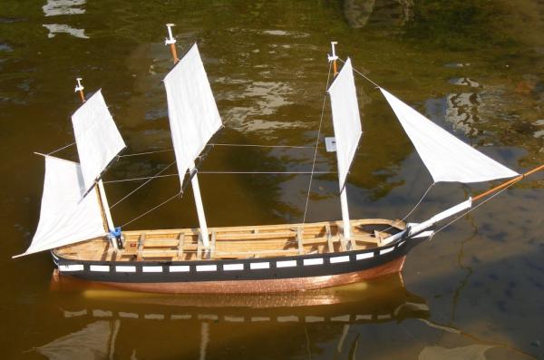
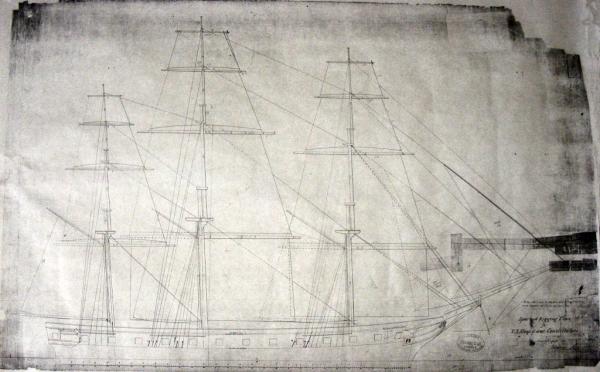
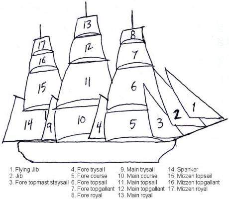
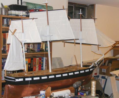
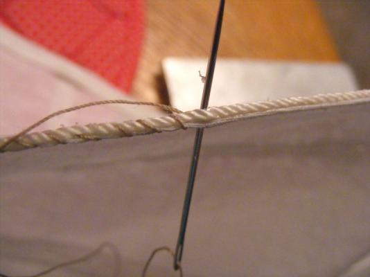
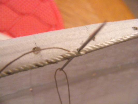
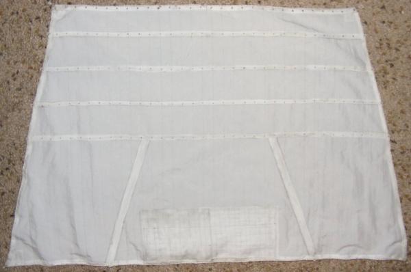
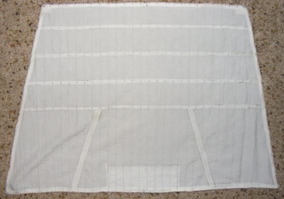
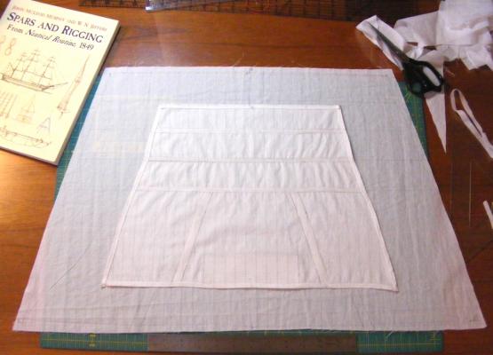
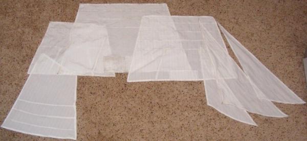
The 1854 sailplan shows 17 sails. There were stuns'ls, though they're not shown. The sails will be made from DuPont Supplex. Supplex is the sail cloth provided with the SC&H kits. It's strong, light, UV resistant, wrinkle resistant, and water resistant. It's typically used in wind-breakers and such garments. Besides, the appearance and performance experienced by my friends Dan Lewandowski and Victor Yancovitch on their models is a pretty good selling point Dan's 1:24 Syren (from an SC&H Grasshopper kit) *** I get Supplex from Rockywoods.com. I got white, but some might prefer the color they list as "Nomad." I think that used to be listed as "Wheat"and is the color used by Victor on his Royal William. Vic's scratchbuilt 1:36 Royal William Constellation will inevitably carry some 2,807.01 square inches (1.8 square meters) of sail, but for now I'm focusing on 5 sails; the jib, driver, and three tops'ls. (#'s 2, 6, 11, 15, & 14). One change I made to the sail plan was raising the clews of the heads'l a little to make it easier to pull them across the stays. Interestingly, this was done to the actual ship's heads'ls at some point as can be seen in the 1862 portrait of the ship. Each sail was drawn on paper full size, and cut from the cloth with a hem allowance added. All sail panels were drawn on with a .05 fine point permanent marker. Tablings were cut from the cloth and the edges heat sealed with a hot knife. These items were glued to the sail with Liquid Stitch fabric adhesive and ironed with a clothes iron. Holes were made for lacings, reef points, etc with the point of a hot soldiering iron, which makes a hole and seals it against runs at the same time. The hem was folded and glued, then folded and glued again and all ironed flat. Then came the bolt rope. This is nylon cord about 1/16" diameter. It's glued with fabric glue and stitched onto the sail as was done on the prototype, except I did a stitch about every three strands instead of every strand. Jib Fore tops'l main tops'l Driver Mizzen tops'l (on just cut main tops'l) All the sails were cut, all the heads'l were hemmed, but only the 5 needed were bolt-roped.


- 553 replies
-
- 5
-
-
- sloop of war
- constellation
- (and 3 more)
-
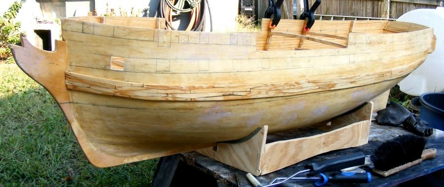
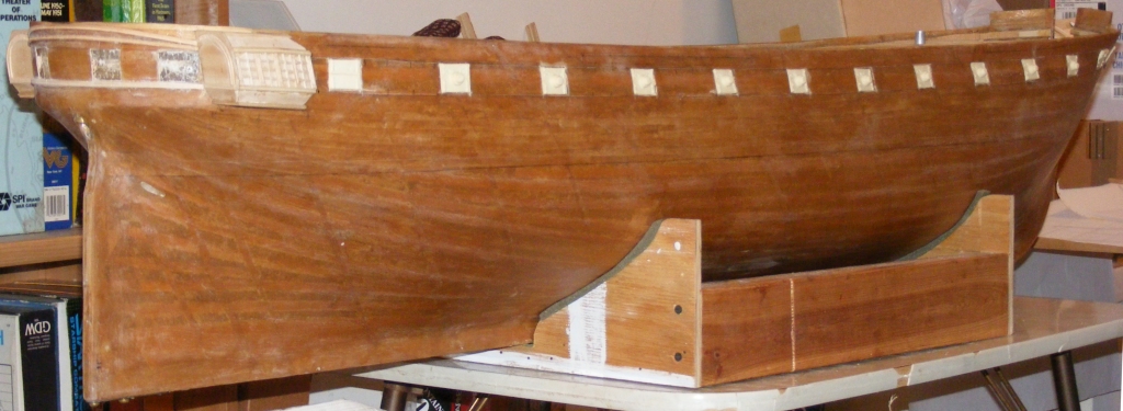
The hull currently currently weighs 9 pounds, and you'll see some more is going on, and some is coming off.
-
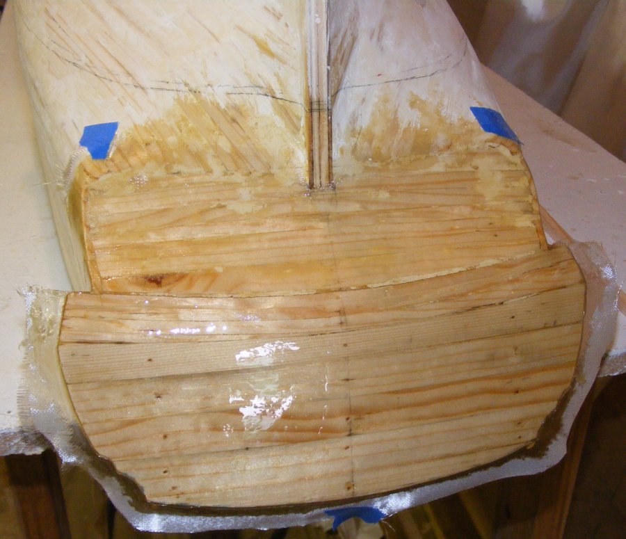
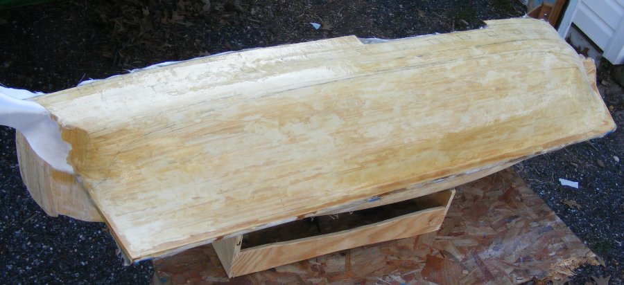
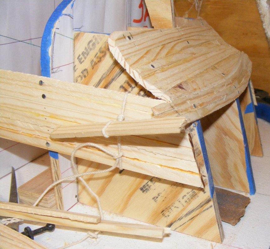
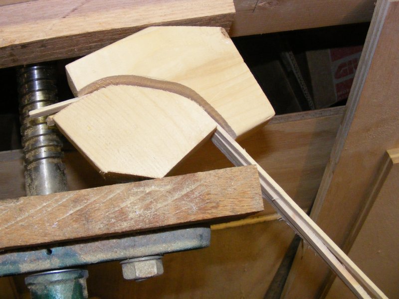
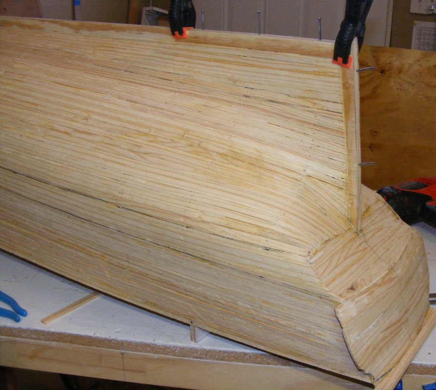
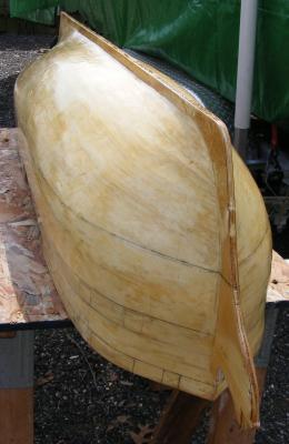
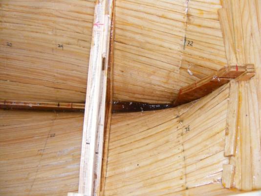
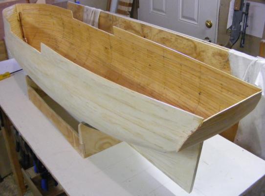
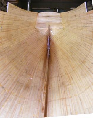
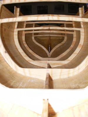
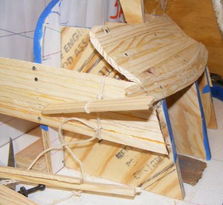
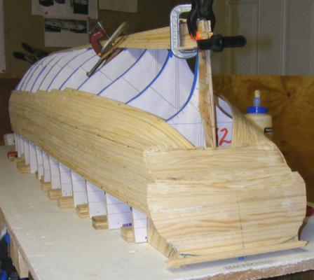
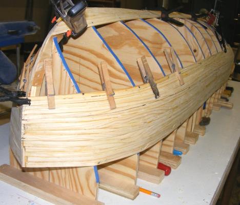
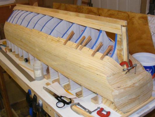
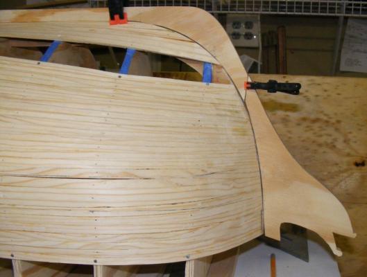
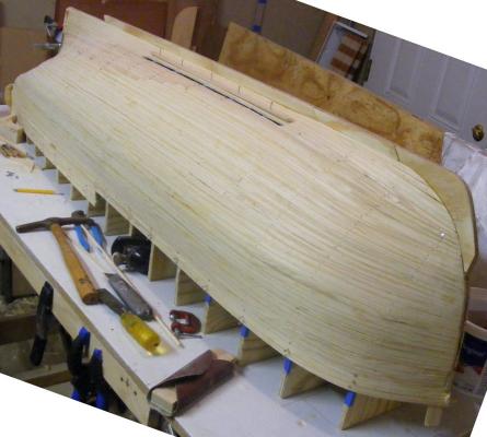
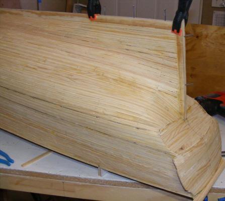
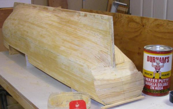
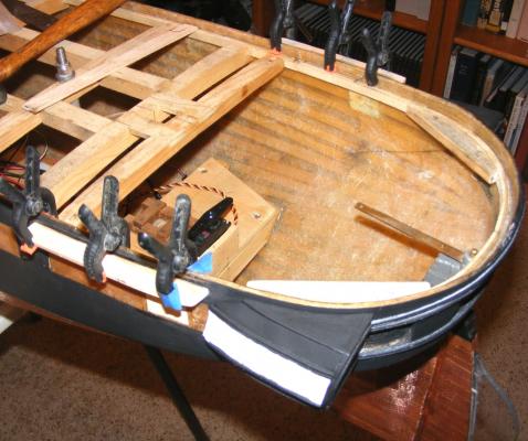
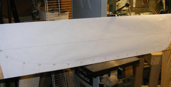
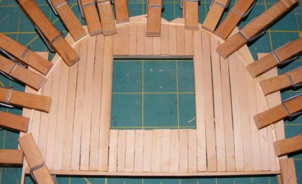
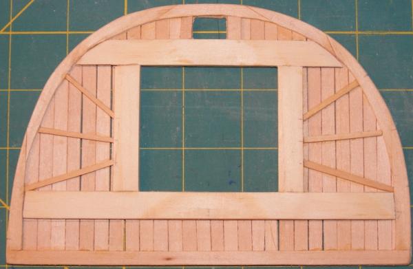
Some blocking was added forward to reenforce and brace the stem The counters were planked and as the side planking proceeded, the counters were trimmed. Planking continued until it reached the counters and could be attached then the transom was planked. Blocking was added to the bottom of the counter to catch the plank ends. At the bow, blocking was added to give more surface for attaching the plank ends here. Planking continued around the turn of the bilge. Now the planks had to make a hard bend up to tuck onto the counter. To prebend tthe planks I wet them and clamped them into a jig. A brace was added to support the top of the transom and prevent it's loosing it's curve. A set of wide garboard planks was also installed to rigidify everything a bit. As the planking continued on up to the sternpost, and with the garboards in place, the keel and sternpost were fitted. A template for the forefoot and stem were made and the forefoot fitted. The hull was rigid enough to remove from the build board, see it right-side up, and look inside. A stem and gammon knee were cut out and fitted and before long it was time to put in the shutter plank. The hull was completely planked. It took from November 12th, to December 19th to plank the five foot hull, 37 days. A couple of days later the stem head and stern post were permanently attached with 6p finish nails reenforcing all of it to the hull. Some of the forms were removed as well; they require a light tap with a block of wood to be knocked loose. Some of them would be cut down and reinstalled as permanent frames. A stand was built to hold the model as she's being worked on. The entire surface of the hull was filled with Water Putty and sanding commenced.


- 97 replies
-
- 13
-
-
- macedonian
- frigate
- (and 2 more)
-
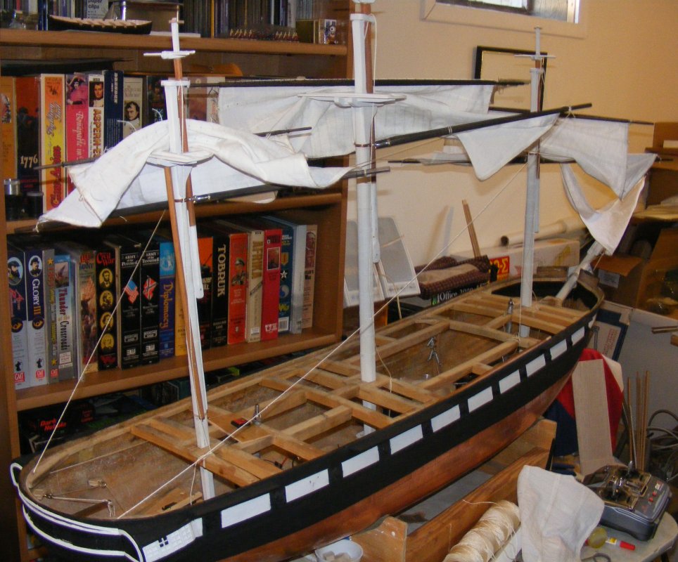
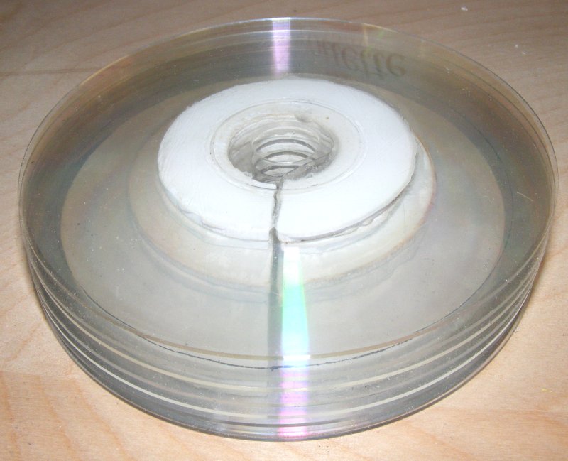
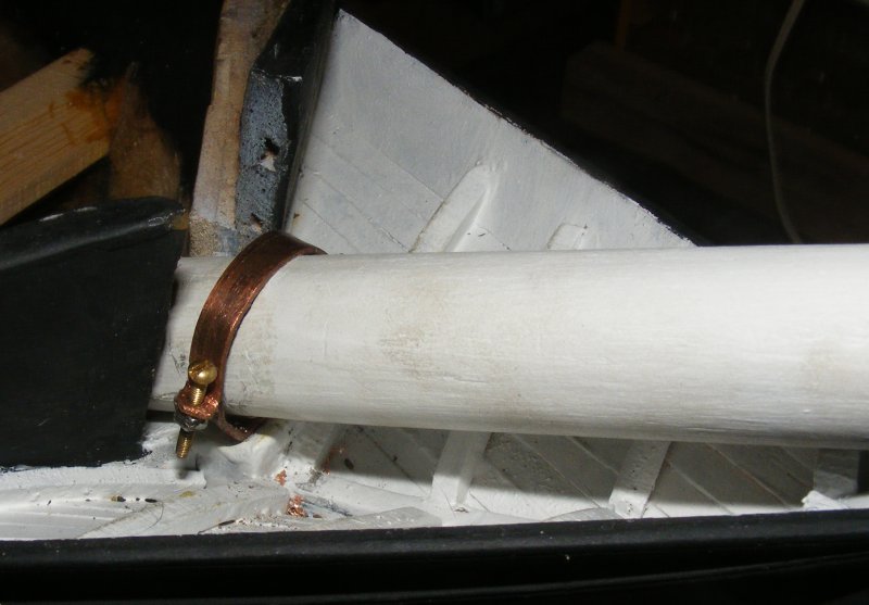
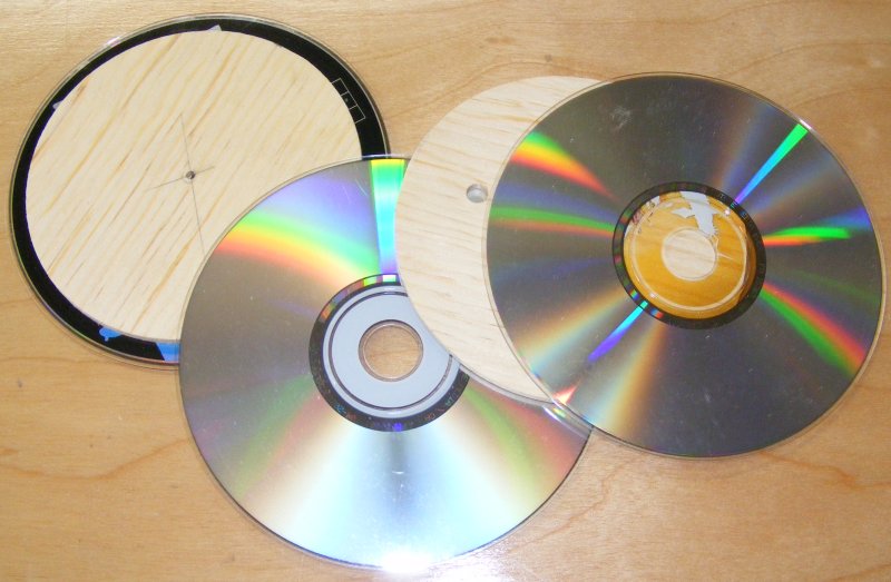
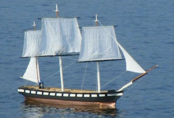
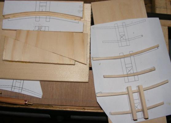
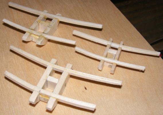
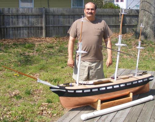
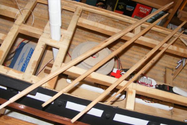
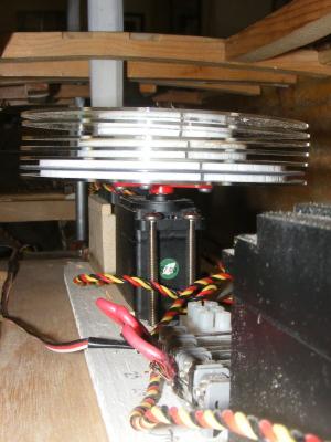
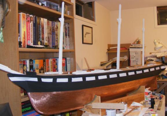
Moving up the masts, I started on the topmast cross-trees and trestle-trees, and the topmast caps. Another item I came across here at MSW was the idea of laminating some items, among them, cross-trees. These are made of bass (lime wood) and laminated in a form just the way I saw it done here. The ends are seized with poly thread and set with CA glue to prevent the t'gallant shrouds from splitting them. The caps were cut from 1/8" aircraft plywood and everything got painted white. Eyes were set into the stem for the bobstays. They're a little over-sized, but I felt there was going to be a lot of strain here and wanted the extra strength a larger diameter rod would give. These eyes are 1/16" brass rod made into eye-spikes and CAed into the stem at 90° to the bobstays. They're connected and reinforced with a brass plate that is glued and nailed to the stem and soldered to each eye. Then it was outside for a photo. Here it was the middle of April, 2010. I wanted to get the hull in the water again, but I didn't just want a float test, I wanted a sail - so I made a goal to jury rig her enough to sail by July. The first weekend available in July was that of the 10th, so that became my goal. There were several items that would have to be done to be able to sail the model, even jury-rigged: Shape the still rough cut yards; fore course, fore tops'l, crossjack, and mizzen tops'l yards. Complete the yard trusses with mast bands and banding to attach them to the yards A gammon "iron" for the bowsprit. Rudder control & steering. New winch drum for braces. Sails for planned sailing suit; 3 tops'ls, Spanker, and jib. A gammon "iron" was made of copper - the same sheet the rudder gudgeon plate and tiller were made from. The actual ship had an iron gammon fitting instead of the traditional rope wrapping. Two copper nuts are soldered to the bottom allowing two copper machine screws hold the two halves of the "iron" together, clamping the bowsprit between them. Another "iron" fitting goes on each cap for the yard's lift tackles to attach to. These, again, were copper and glued and nailed to the cap. The required yards were shaped The original drums for the winch servos were made of wood disks sandwiched between plastic compact-discs. These warped so I made a new one substituting 1/8" thick sheet styrene for the wood disks. The steering set-up for the rudder mentioned earlier was put back in place. The trusses were attached to the course yards with brass banding held by nuts and bolts. Threaded eyes were attached and copper banding made for the masts. All that was left was to make The Sails


- 553 replies
-
- 3
-
-
- sloop of war
- constellation
- (and 3 more)
-
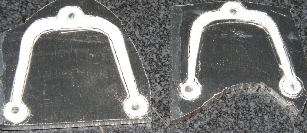
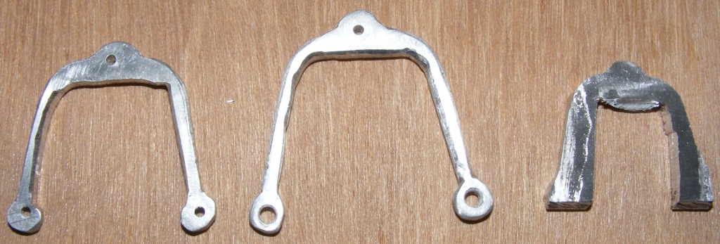
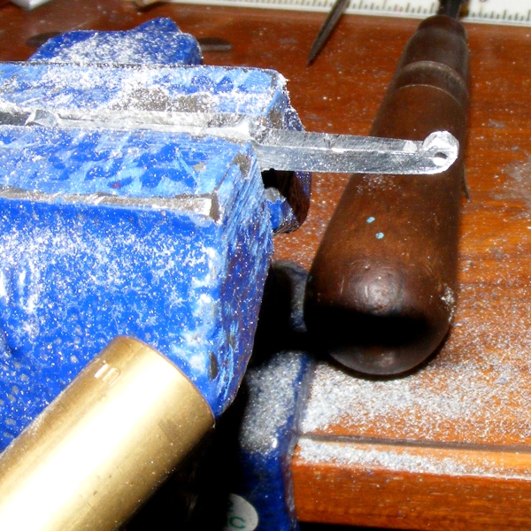
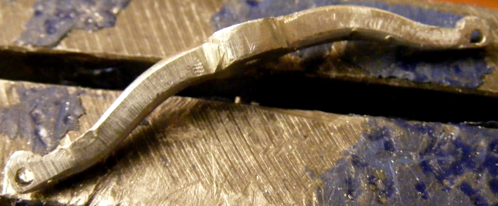
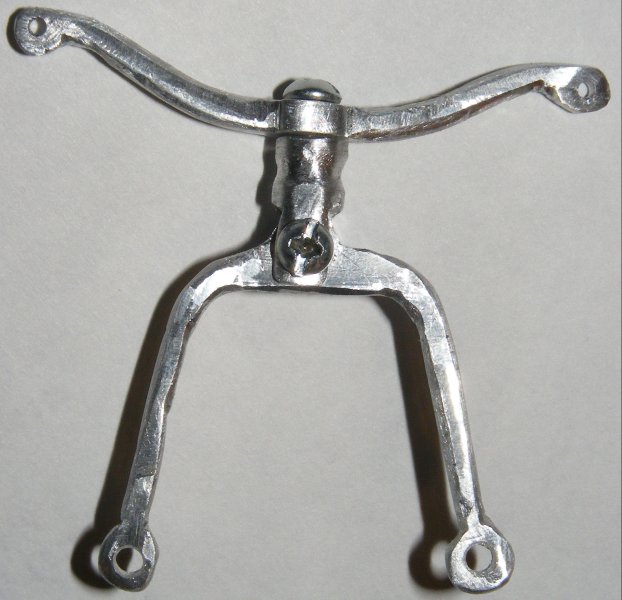
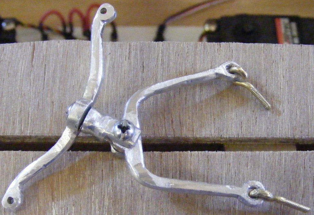
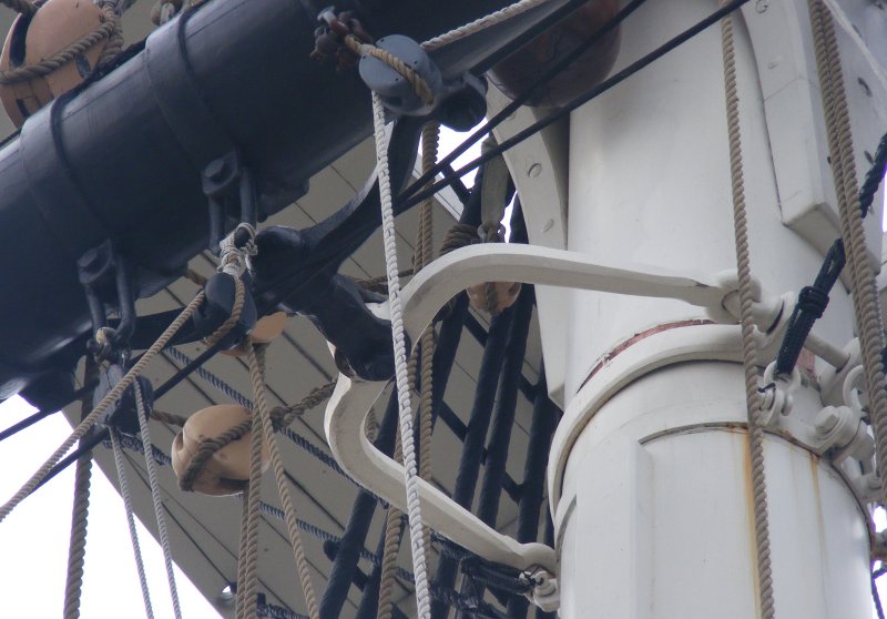
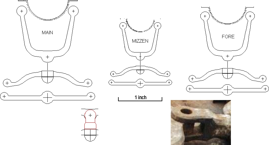
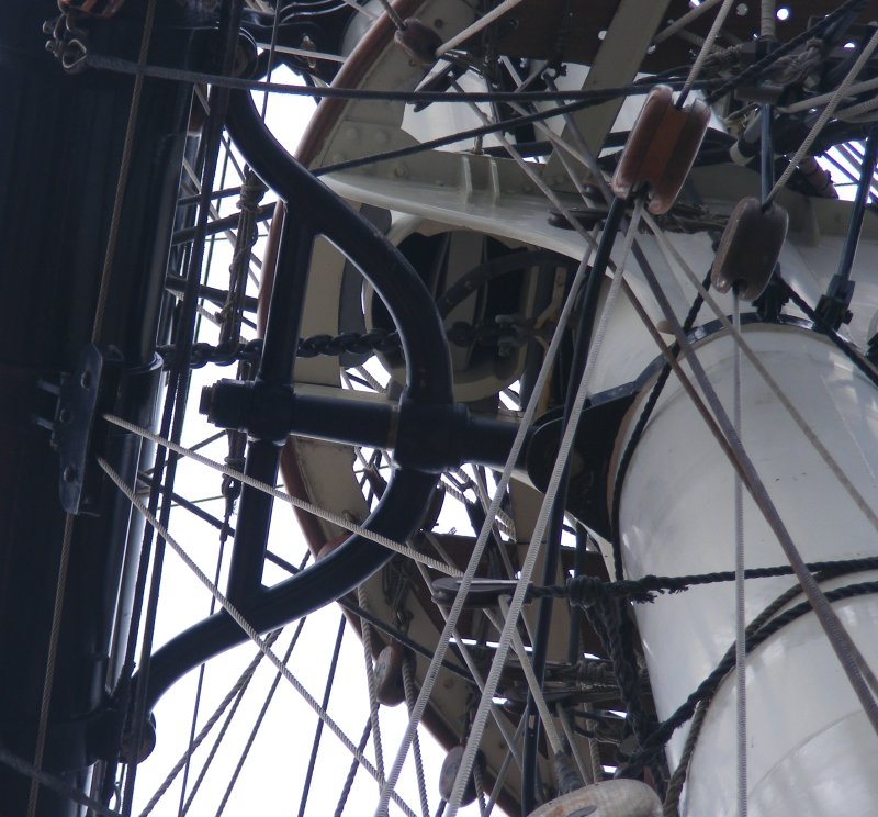
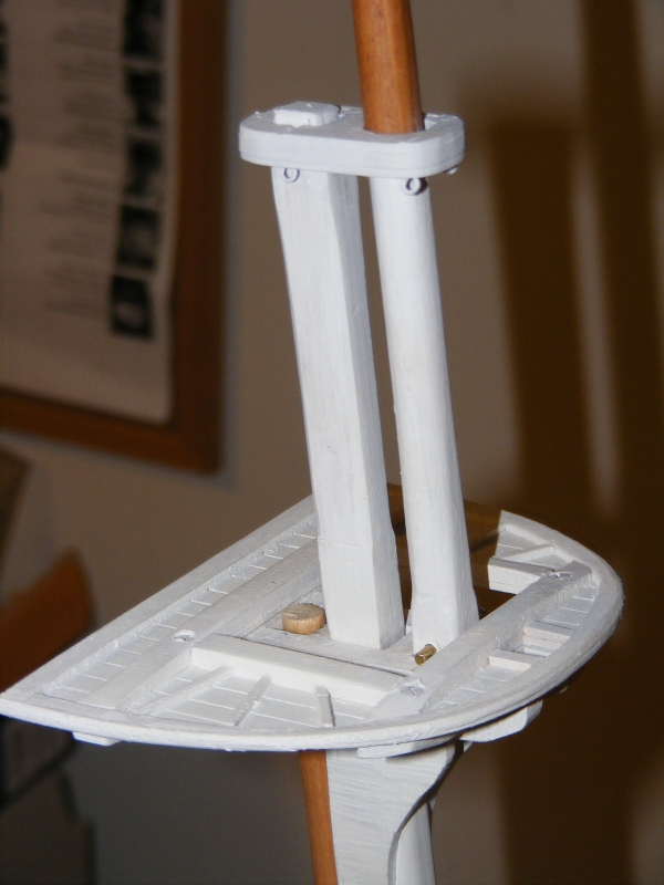
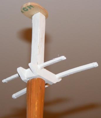
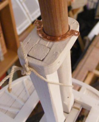
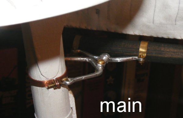
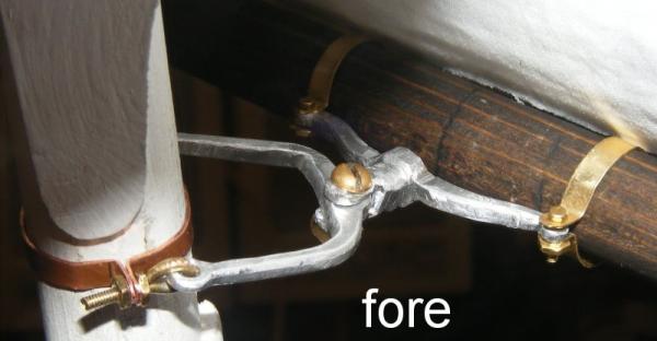
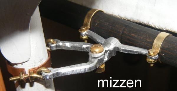
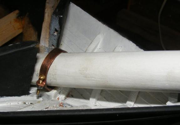
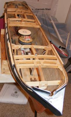
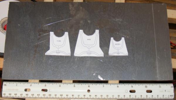
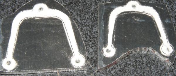
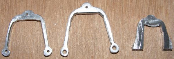
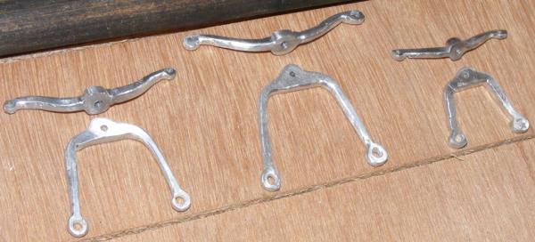
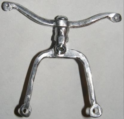
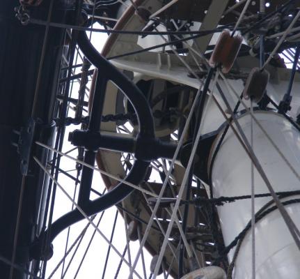
Channels, Quarter Galleries, and Paint The channels were made from pine and their shape, position, and size were taken from the 1888 spar deck plan, as will be many other deck details. The Archives listed an 1854 spar deck plan, but it was, and still is, missing from their files. It was time now to repaint. Painting up to this point has only been a quick job of spray painting, now I was going to finish the gun stripes properly, and get into some nooks and crannies. I don't know what these things are called, the only name I've seen is "drops," so, I made them of sheet balsa laminated into blocks which also meant the quarter galleries were finally and permanently affixed to the hull with epoxy and the screw that had held them since their beginnings. The insides of the quarter galleries had been thickly painted in resin some time ago, in case any moisture managed to get inside. The gun stripe now went through the head as it should, and the masts and tops also got some fresh paint. Course Yard Trusses Constellation's course yards are attached to the lower mast via a set of iron trusses. These are really quite impressive items that will be as important in the operation of the model as they undoubtedly were on the ship itself. Unlike the trusses on the clipper ships and most modern square-riggers; Constellation's pivot out further from the mast where the more common type pivot at the mast and hold the yard off on a post. This allows the yard to be braced further over and allow the ship to sail closer on the wind. Constellation's truss design also allows the top masts to lower through them without having to disturb the yard in any fashion - something that will help me lower the rig on the model for transporting. <= Stad Amsterdam <= Constellation It's very fortunate to have the actual ship available to reference, and that so many of her original fittings survived the attempt to make her into a frigate - these trusses for instance. Using a photo of a truss on the ground and my own photos taken from on deck, and using the diameter of the masts for proportion, I designed a set for the model. I ordered a sheet of 1/8" thick aluminum online and began cutting out my parts on a band-saw with the narrowest blade I could get. I'm not really set-up for working with metals, but I trudged along. Cutting out the parts was tough enough, making the bows made that seem easy. The bow's center bulge was vertical and swelled to as much as a 1/4" while the ends were horizontal. I opted to get this shape by heating and twisting the ends. First I drilled them, then I heated them, then carefully twisted the ends 90°. Most of them worked out very well, but a couple broke and had to be remade. With some filing you can see they're twisted at all. The remaining part to make were the clevis'. This was made from some aluminum rod, drilled, slotted, tapped, and shaped with files to match the iron clevis' of the real thing. Here's a shot taken a bit later showing the top mast lowered through the truss:


- 553 replies
-
- 6
-
-
- sloop of war
- constellation
- (and 3 more)
-
I was rereading Hornblower while waiting to be called for jury duty when someone noticed and asked if I was familiar with O'Brien's series. I wasn't, but during our lunch break I walked over to the bookstore (I was in Annapolis) and found the first book. I had read a biography about Cochrane a few years before and I was actually very disappointed by what was basically a blatant theft of Cochrane's early career for some novel. Further, the first book is the longest of the series - it's certainly the slowest. It very nearly ran me off, but O'Brian was very good at immersing you in the period, so I struggled through, though most of the time it was an exercise at staying awake. I felt that I had to do a lot of work to care about these characters, O'Brian only gives you this external view and Aubrey is more of a caricature. It's an early 19th century maritime odd-couple. I haven't read all the Hornblower knock-offs out there. I read several Bolitho books and hated them. I'm told most other series are better, but I find that modern writers can't write, and nothing I've read yet gets across the feeling of the period like O'Brian and Forester, who were both from a pre-computer time. What I've read so far seems to have been written in a hurry with a pay check always in mind - like television. Forester's The Captain from Connecticut got me into this back when I was around 10, and I've reread the Hornblower series several times, nothing yet compares. The Good Shepard, The African Queen, the Gun, all are great stories well told. O'Brien was good, Forester was great.
-
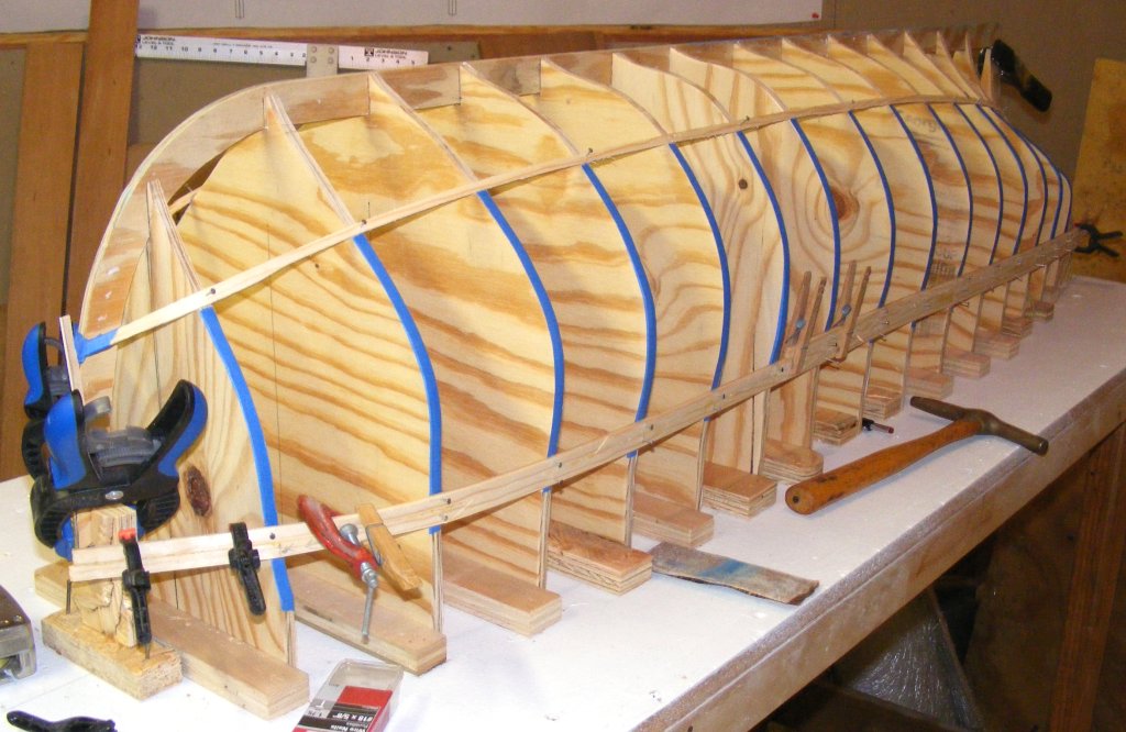
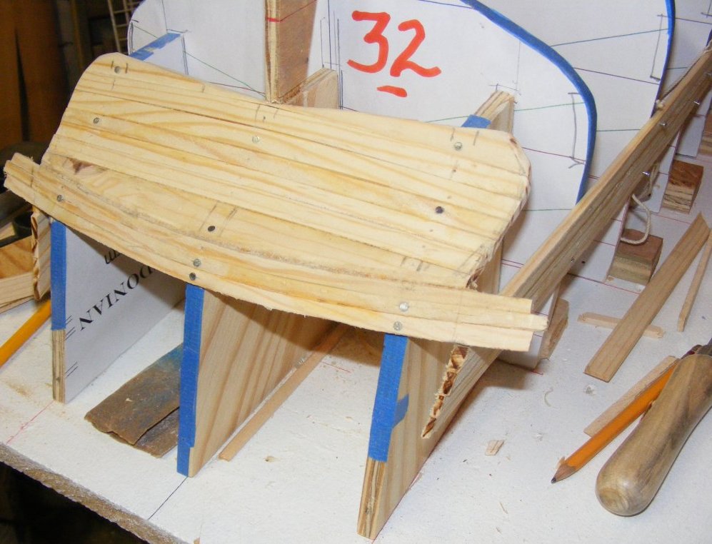
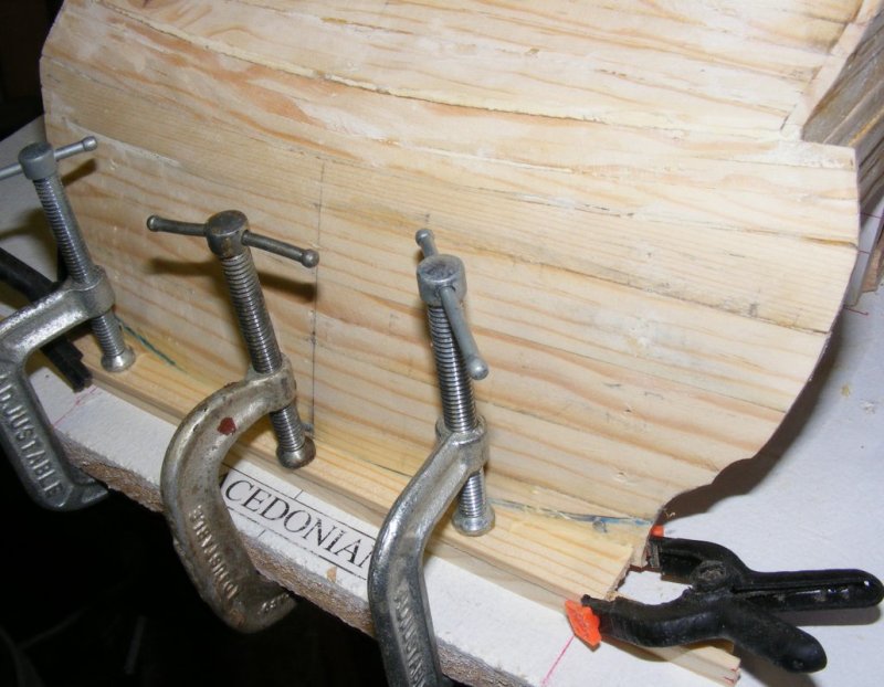
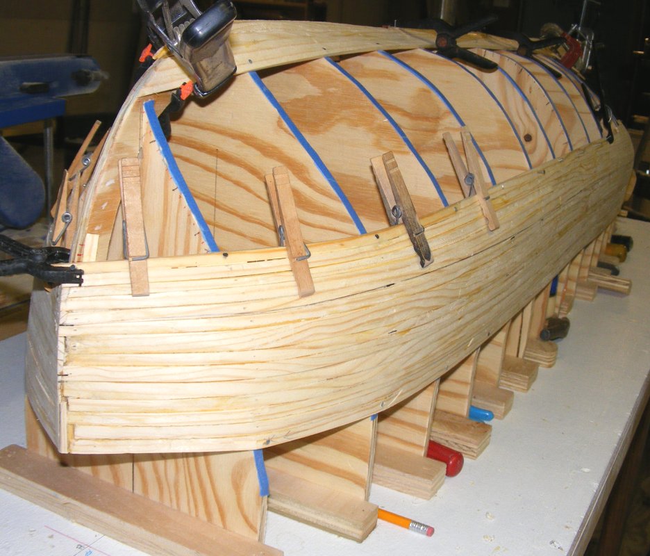
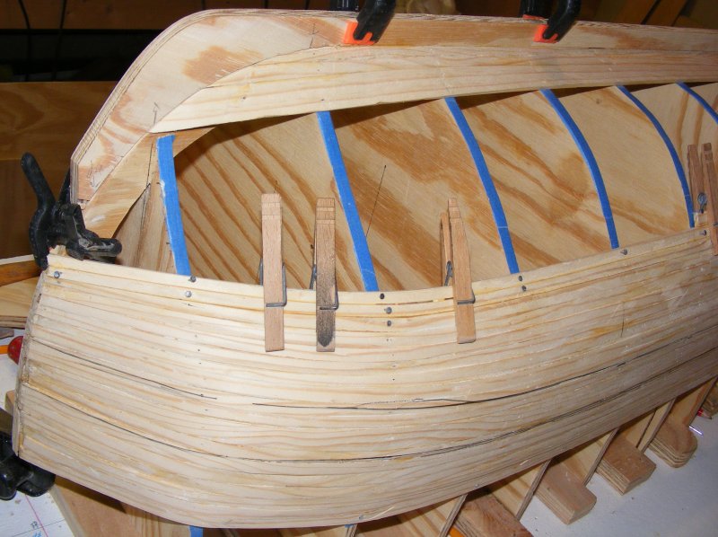
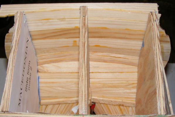
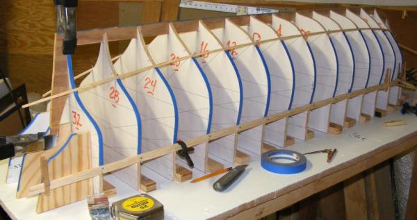
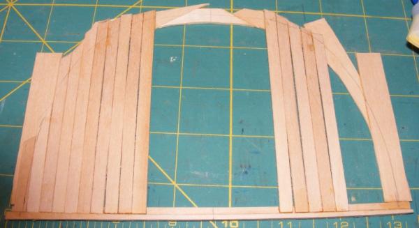
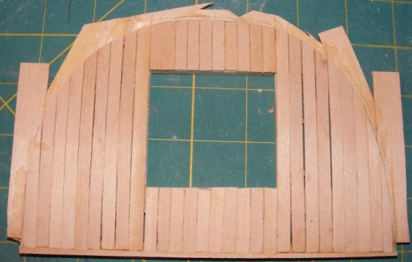
The building board that Constellation had been attached to since 1999 and the Pride of Baltimore was built on, was showing it's age, but was still good and flat (not warped). It had it chips and dings repaired, holes filled, was sanded, and given a couple of coats of flat white paint. It was then marked with a center-line and lines for each of Macedonian's stations. Each plywood form was attached to a strip of wood to allow it to be stood up and attached to the build board at it's station line. It wasn't really clear to me how the stern came together based on the drawing, but studying several of the fully framed models here on MSW helped me figure it out, and how to deal with it in my particular, and peculiar construction method. Forms were devised for the construction of the stern and the aft perpendicular form was discarded. A keelson was cut from 1/4" plywood and corresponding notches were cut in each form to receive it. It isn't glued or fastened to any of the forms as it will become part of the model where the forms will be removed. The edge of the forms are taped to prevent the planking from being glued to them, and a batten was nailed to the lower diagonal to steady everything. Planking then began with 1/8" x 3/8" pine strips starting at the sheer strake. I used 3/8" common nails to hold things in place. I used smaller nails on Pride of Baltimore that were almost like straight-pins, but these bent so easily they became quite frustrating. The next strake was glued to the sheer strake, and pinned and clamped in place. This, basically, is how all the planking was installed; each strake glued to it's predecessor and finally to the keelson, stem, sternpost, and counter forming a wooden shell of a hull.

- 97 replies
-
- 10
-
-
- macedonian
- frigate
- (and 2 more)
-
The lady I'm with comes from the land-locked country of Oklahoma, and doesn't really get things maritime. I did have to take up square-dancing though, but then those are the sacrifices we make for our hobby. I wanted to do the Baltimore Clipper in 1:36, but there just wasn't enough room in the hull for the controls, or much else, so I went with 1:20 scale, which makes the overall model about the same size as Constellation and Macedonian. This is about as large a model as will fit in a van or SUV with the rig lowered, though I hope to eventually make a trailer for them so I can keep them fully rigged in transport.
- 97 replies
-
- 4
-
-
- macedonian
- frigate
- (and 2 more)
-
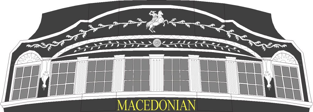
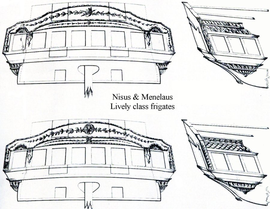
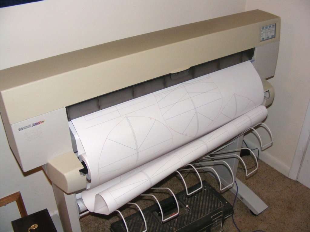
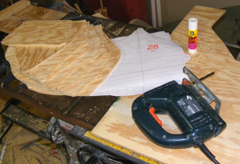
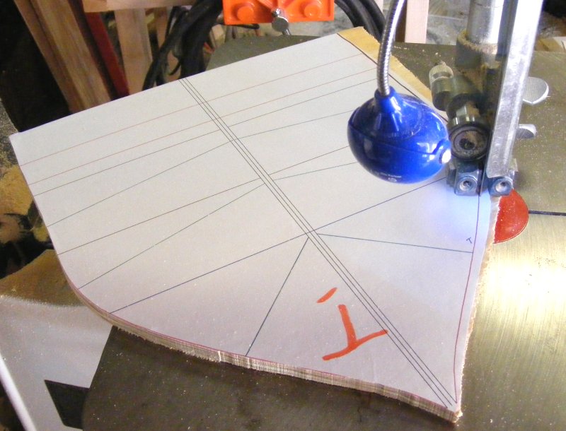
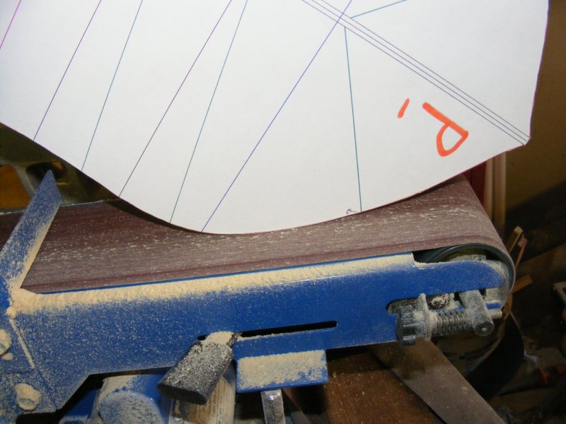
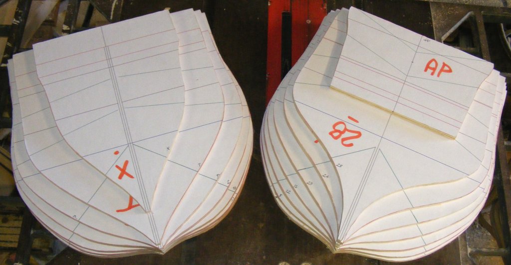
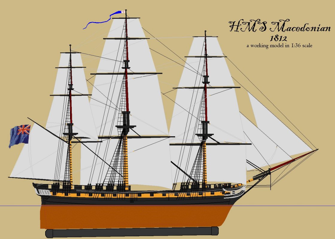
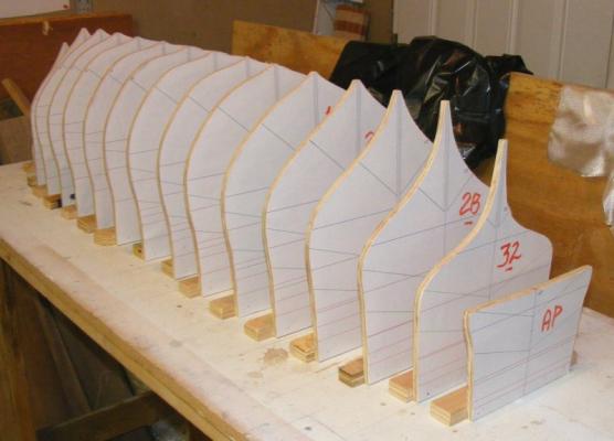
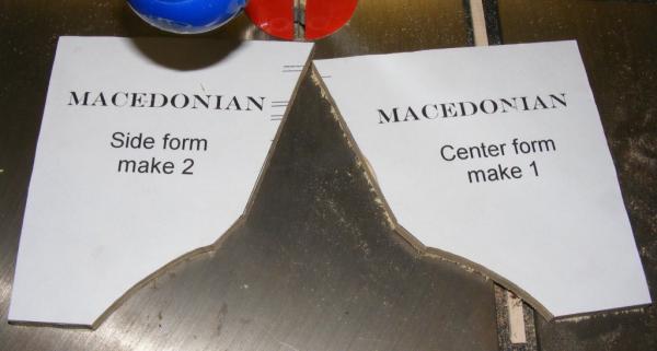
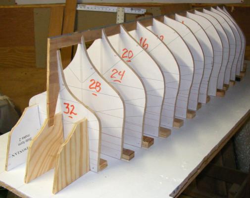
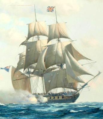
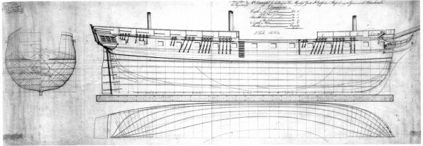
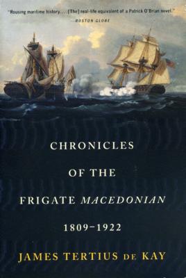
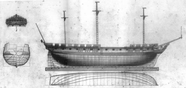
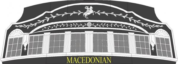
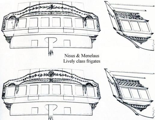
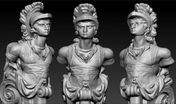
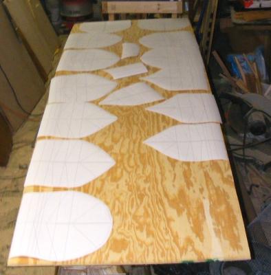
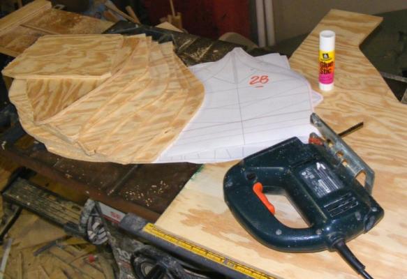
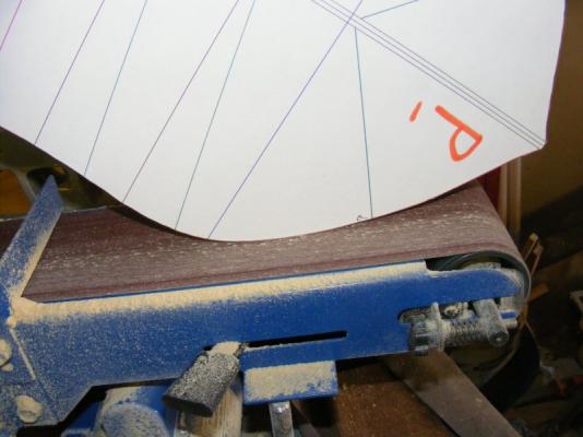
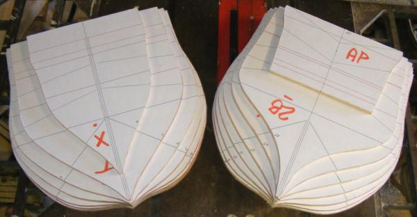
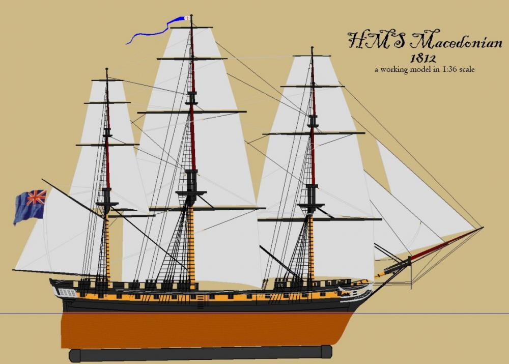
I first set foot on board the Constitution when I was 7 years old, and I was hooked on sailing ships ever since. My elementary school library had C S Forester's The Captain From Connecticut which I loved and led me to Forester's other work, namely Hornblower. In fact, the 16 foot daysailer I've had since 1979 is named Lydia. I spent my teens and twenties working under sail and power, from barkentines to tugs. I've built several of the 1:96 scale Constitution/United States Revell kits, two of them were RCed; but I always wanted a sailing model of the ubiquitous British frigate, and no one made that kit. I finally decided to build one. Already deep into building an 1850's American sloop-of-war, and with a Baltimore Clipper schooner already planked up, I began a third model of the HMS Macedonian. I chose Macedonian because I could easily get Chapelle's drawing of her from The American Sailing Navy from the Smithsonian, and she was interesting. Macedonian by Gardner Macedonian was a Lively class frigate rated at 38 guns, another of Sir William Rule's designs. Launched in 1810, during the War of 1812 she had the misfortune to meet the American frigate United States, a Constitution class 44 and was captured. She was taken into the American Navy and served until 1828 when she was broken up and replaced by a new ship. Lively Bacchante The story of Macedonian is well told in Chronicles of the Frigate Macedonian, 1809-1922 by James T deKay and I've posted a fair history of the ship on my page There's lots of data available on how the British built and out-fitted their frigates, and even Macedonian's figurehead still exists, but I never have found any reliable information on what her stern looked like. What I've come up with is my own conjecture based on the sterns of other Lively class frigates. The mounted figure is from a statue of Alexander that existed when Macedonian was built. The round object is the "Vergina Sun" found at ancient Macedonian sites and dating from the time of Alexander's father. Symbology available when Macedonian was built and while this is my own guess, it's at least a logical guess. I considered using Alexander's profile from a coin in place of the mounted figure, but his face is already on the bow - given the choice, I'd think an English builder would choose the horse. When the drawings came in from the Smithsonian, the first thing I did was have them digitally scanned. I then rescaled them from 1:48 up to 1:36 mostly so this model would be the same scale as my Constellation. That done, I made up a sheet with each station drawn full-sized, and printed that on my plotter. At this scale, the model should be; Length: 59" taffrail to Alexander's nose Beam molded: 13.3" Draught: 6.87" without the removable ballast keel Her length over the rig will be about 7' and she will stand from keel to truck, about 4'. (I'll update this with more accurate numbers and metric equivalents at a later date) These paper patterns were used to rough cut the wooden stations from 3/8" plywood. Each paper pattern was then glued onto it's station close cut on the bandsaw, and then fined up on the beltsander where some bevel was put into the forward and after stations.


- 97 replies
-
- 12
-
-
- macedonian
- frigate
- (and 2 more)
-
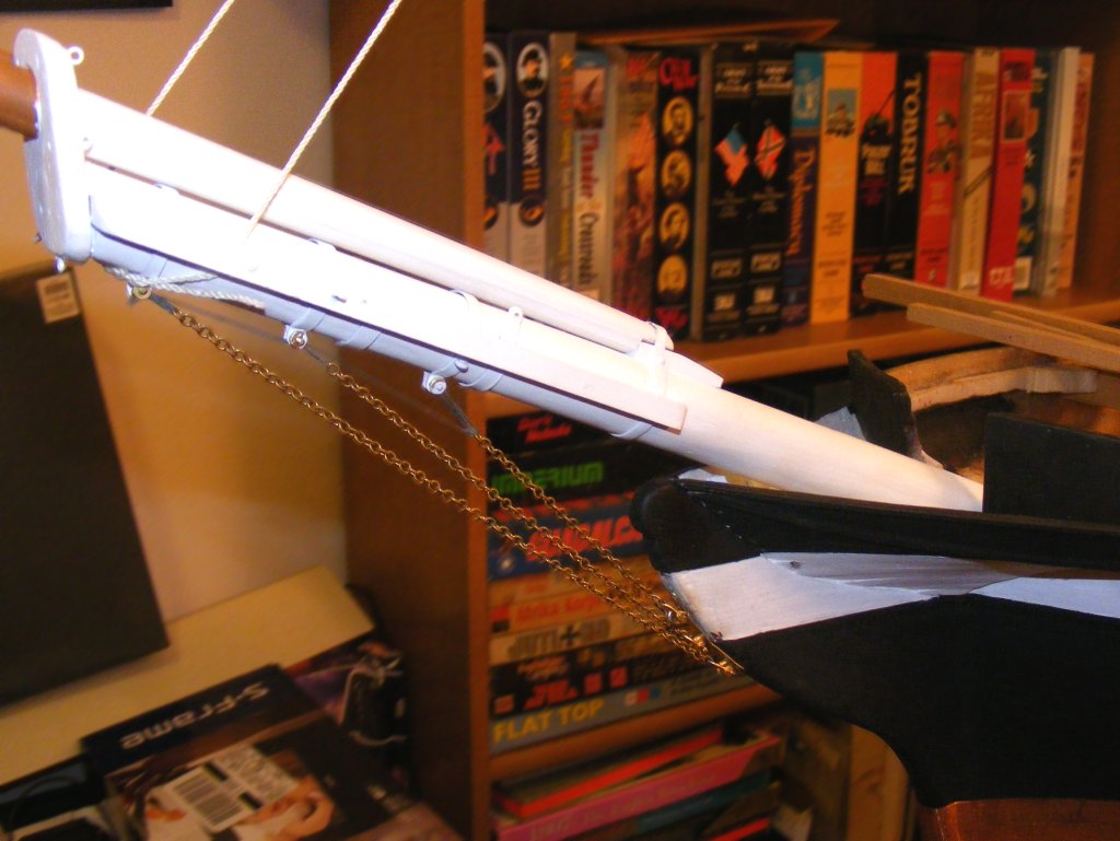
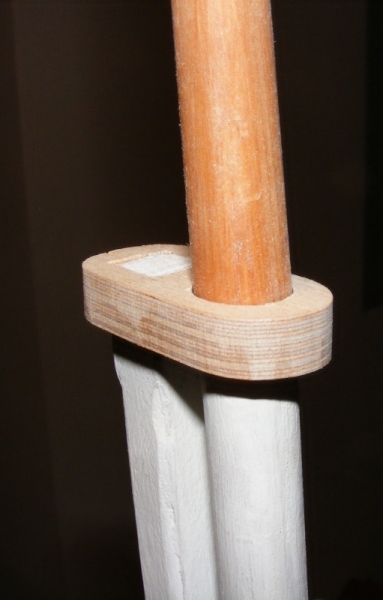
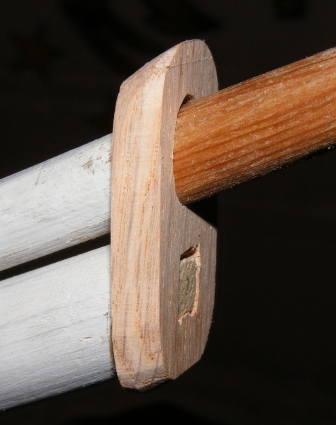
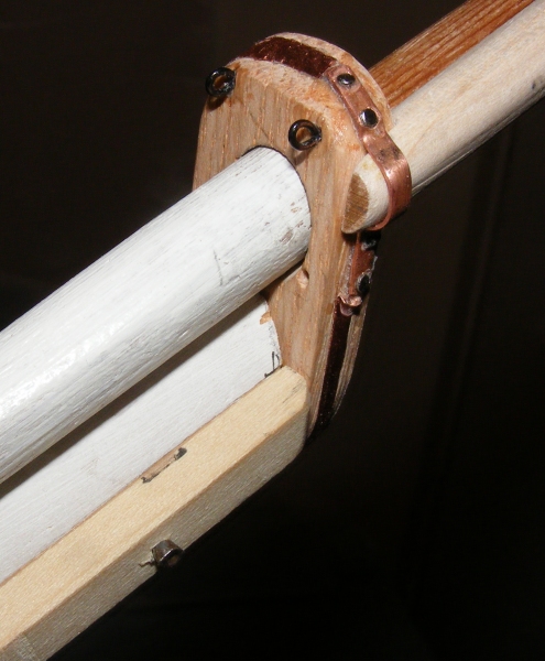
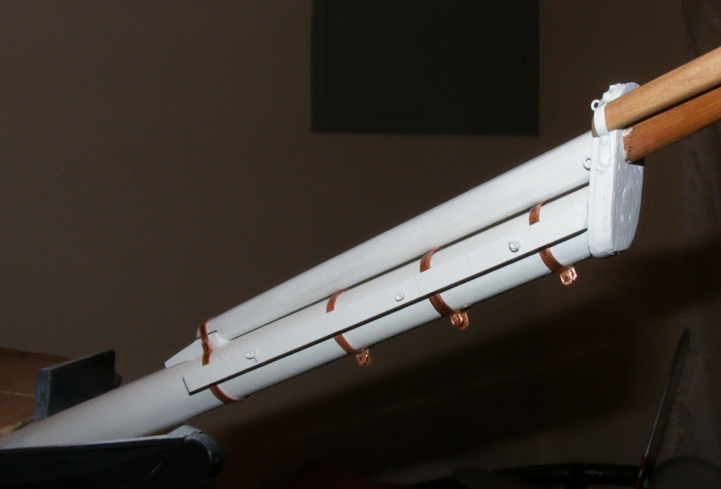
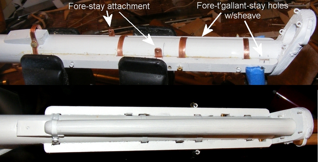
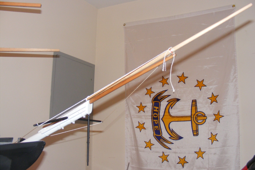
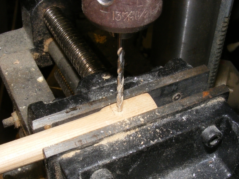
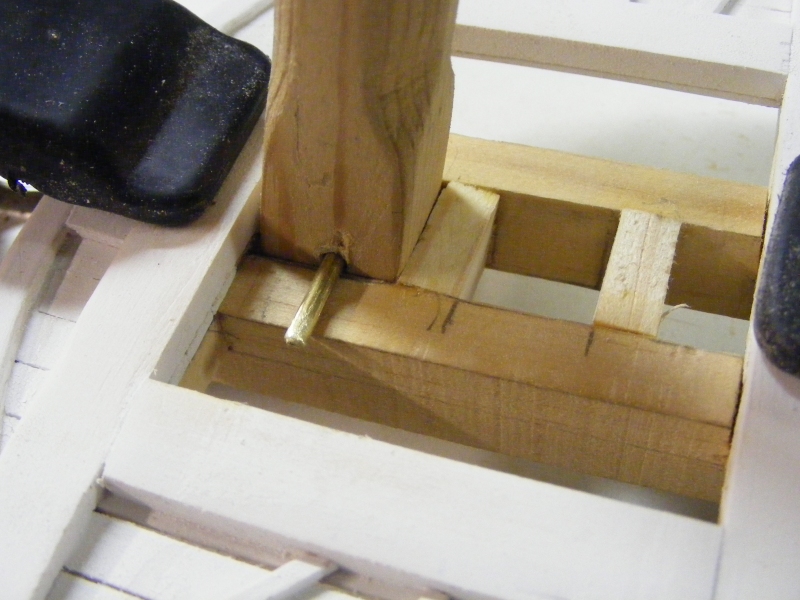
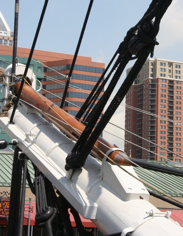
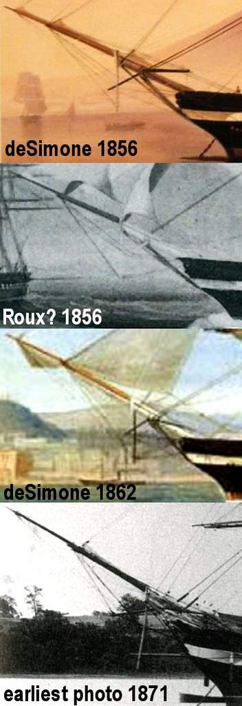
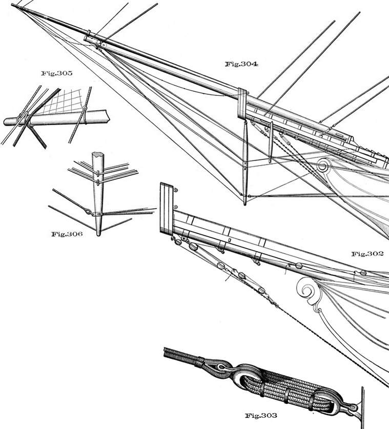
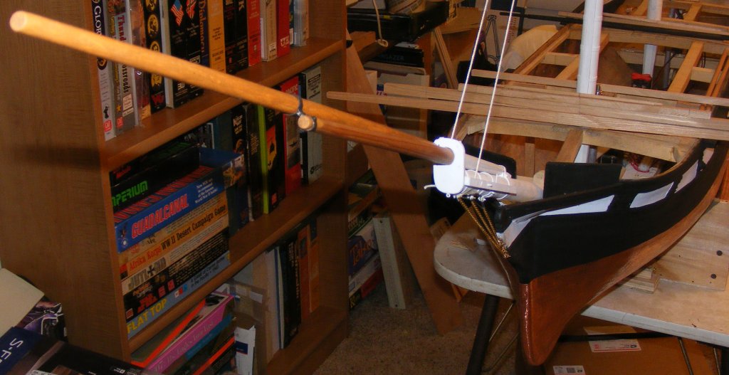
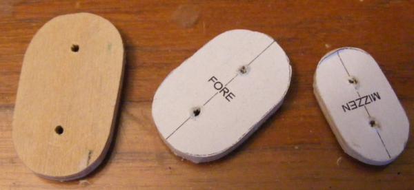
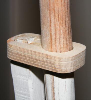
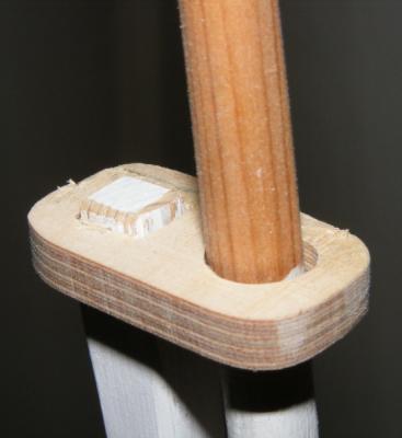
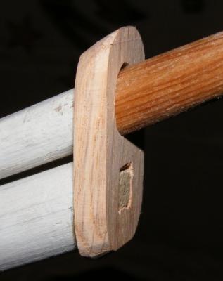
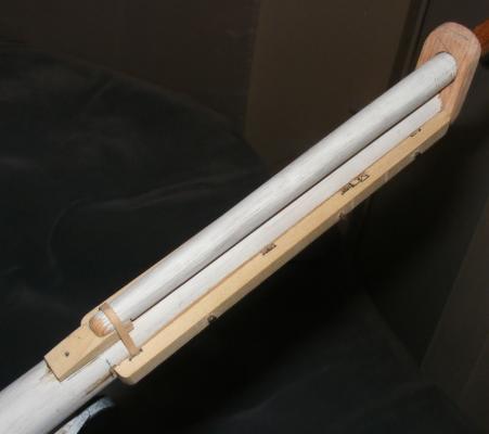
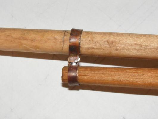
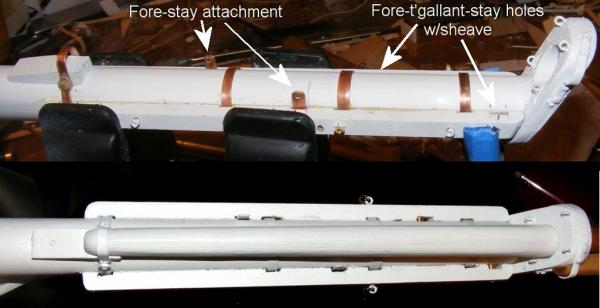
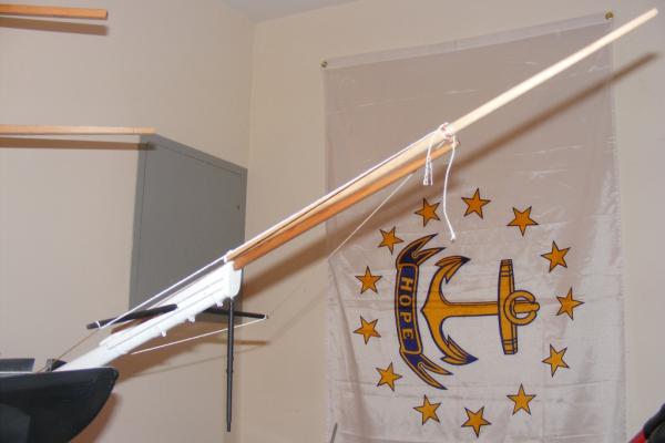
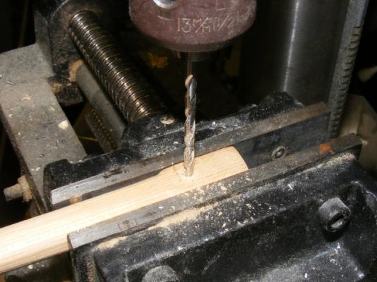
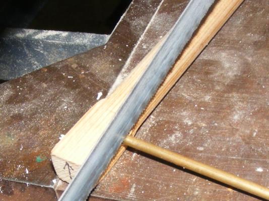
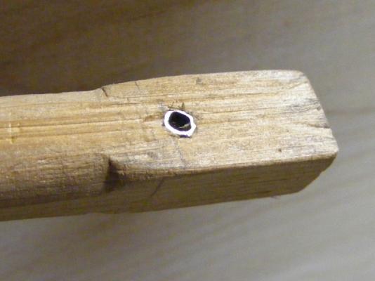
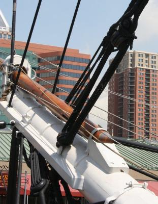
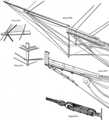
I'm using brass rod for the topmast fids, but I drilled and inserted some brass tube into the topmast heel to strengthen the fid hole. Metal plate will be put on the bearing surface of the trestle-trees. The caps I made were just rough outs, so I made a new set from laminated aircraft plywood and one of oak for the bowsprit. The caps got some eyes installed, and the tops got blocks for the heads of the trys'l masts, then everything got painted. The bowsprit started with a bit of research. The paintings of the ship in 1856 and 1862, the earliest known photo from 1871, and the rigging documentation of the period all agreed closely enough. I basically used "Plate 51" from Luce's Textbook of Seamanship 1891 edition along with the 1871 photo as my guide's. The heel block for the jib-boom and the bees got things started. The heel block is notched into the bowsprit, glued, and pinned - I think it'll stay there. The jib-boom was notched to fit The cap was banded with some of the copper tape used on the hull's bottom, and some eyes. It also got some copper strap glued and pinned to take the notched heel of the flying jib-boom. A "wythe" was made from copper and it was glued and bolted to the shouldered end of the jib-boom. The flying jib-boom slides out through this and steps into the strap on the cap. Banding for the bob-stay chains, fore-stay, and the heel strap for the jib-boom were all made with copper sheet. The heel strap is also bolted through the heel-block. The forestay bands are anchored with a copper nail under the bees and wrap under the bowsprit and through the bee on the other side. The holes in the bees for the t'gallant fore-stay are sheaved with 6mm brass sheaves. The bees were permanently attached with 4p finish nails as pins, brass nails through the t'gallant fore-stay sheaves, and glue, of course. A set of spreaders and a dolphin-striker were made from maple, fitted with hooks, and everything was painted and stained.


- 553 replies
-
- 4
-
-
- sloop of war
- constellation
- (and 3 more)
-
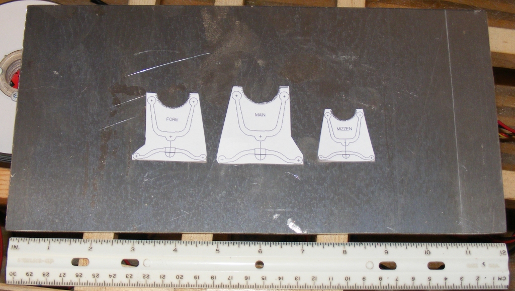
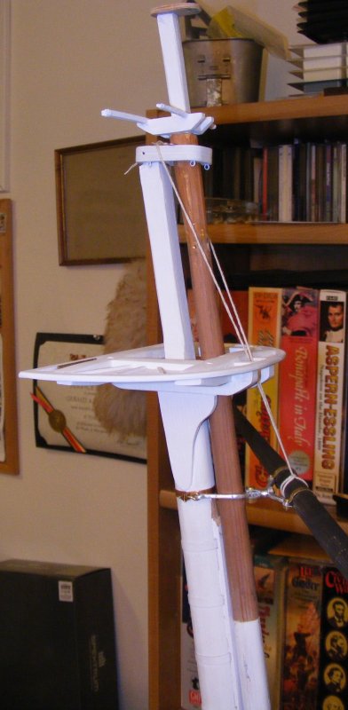
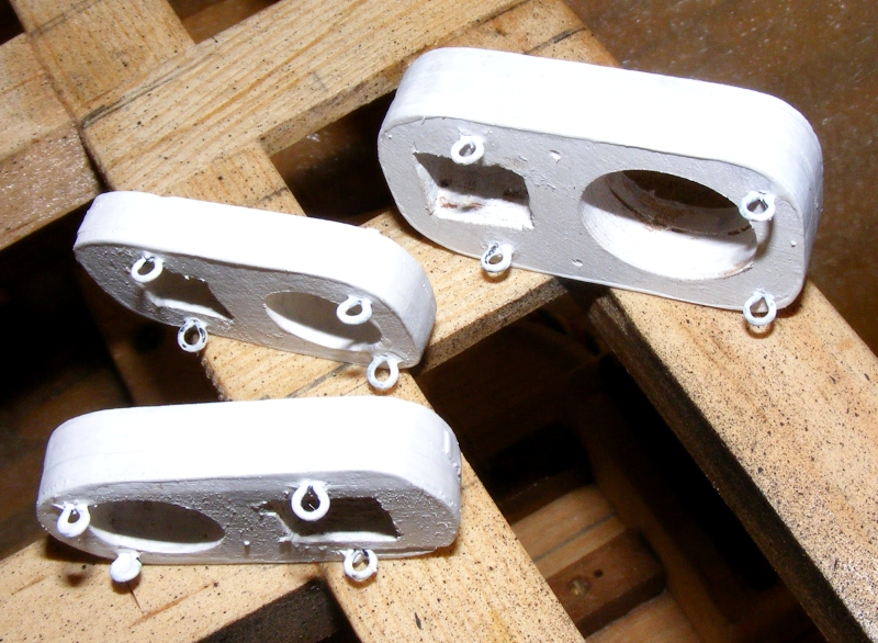
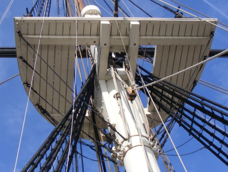
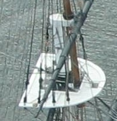
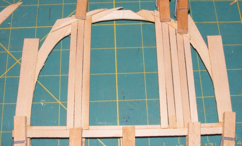
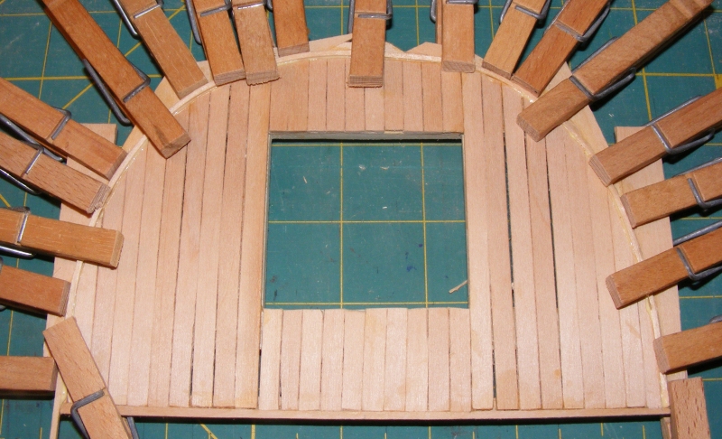
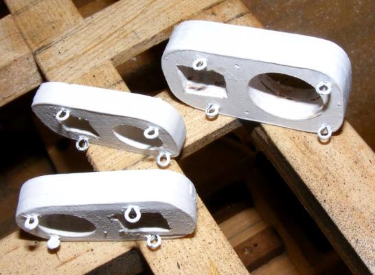
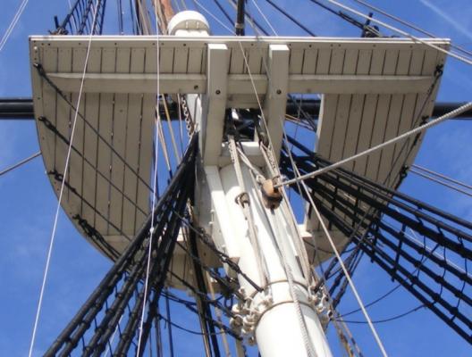
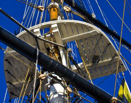
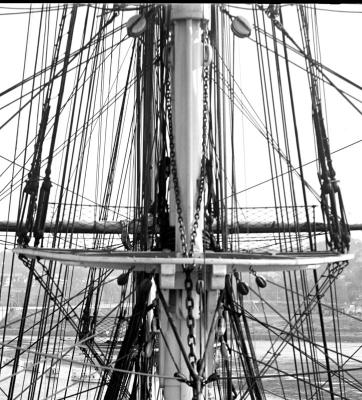
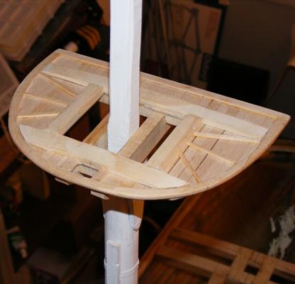
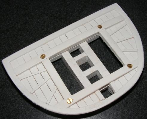
After completing the copper on one side of the hull, I took a break in the form of making the mast tops. As with much of this vessel, I had to figure out what would be right for the ship as she was when new. I looked at the restored vessel, but I've already found things they've done that weren't right for the period they say she's representing, and I would find the tops were no exception. While they appeared from below to match the standard practice of the day... From above they did not. Standard practice called for "sleepers" that sandwiched the very thin and light platform between them and the cross-trees and trestle-trees below, as can barely be seen in a 1914 photo of the maintop (left) and which are absent in the image of the restored ship (right): I had made the cross-trees and trestle-trees back before I fiber-glassed the hull and had worked out the proper size of each of the tops from rule-of-thump combined with proportions derived from photos of the ship like the one above. Now it was time to make the platform. The platform of the top is basically a rim under which is laid the decking of the platform, you're seeing the underside in these photos. I built mine up, then trimmed the inside edge to shape. I laid the decking with slight gaps between them as seen in the oldest photos of the ship. The decking was trimmed back just inside the finished edge of the top... Another rim was bent around the edge of the decking under the top-rim that basically covers the end-grain of the decking. The untrimmed excess of the top-rim gave my cloth-pins something to hold on too as they clamped this piece in place. Once set, the platform was trimmed to it's final shape, the hole for the yard sling made, and the sleepers and compression cleats added. After painting, the platform was screwed to the cross-trees with countersunk brass screws, they were not glued. Next: The Bowsprit


- 553 replies
-
- 3
-
-
- sloop of war
- constellation
- (and 3 more)
-
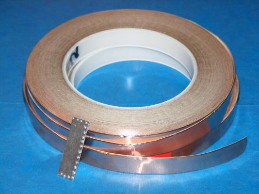
Thanks for all the "likes." Ed, I'm a big fan of your Naiad and Victory logs - I saved all your Naiad images for reference as I do my Macedonian. There's a direct link to the tape in post #26 just above the picture of the tape. It's 1.4 mil thick and self adhesive with a paper backing. At the time, I found it a bit cheaper than the model ship shops were selling it for, where you could find 1/2" wide tape. When I get this build log caught-up, I plan to repost the Macedonian build log, and I have another plan for her copper bottom, I'll elaborate on that when I post on Constellation's boats.
-
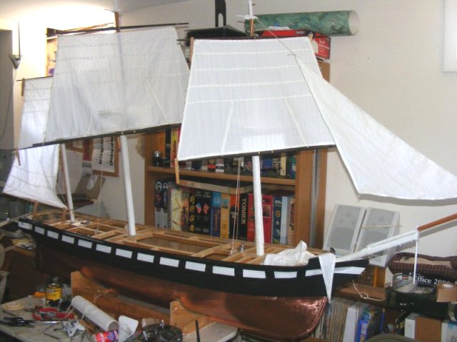
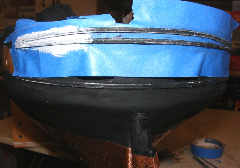
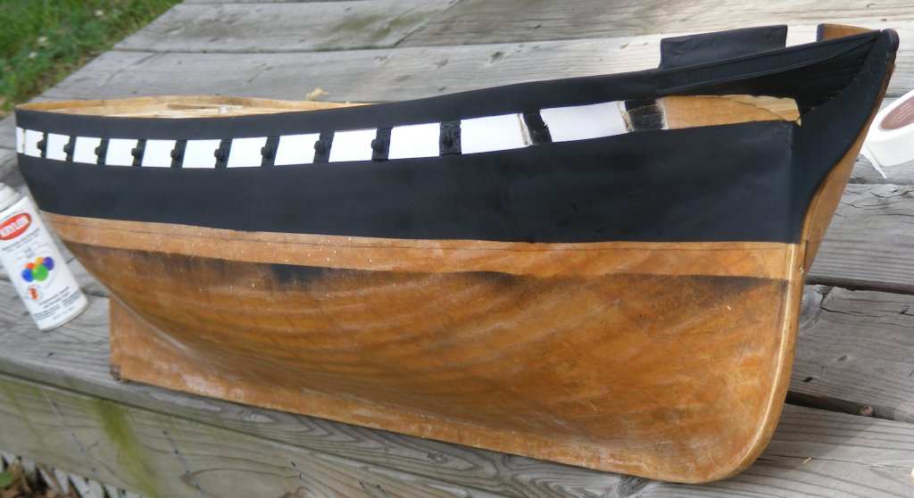
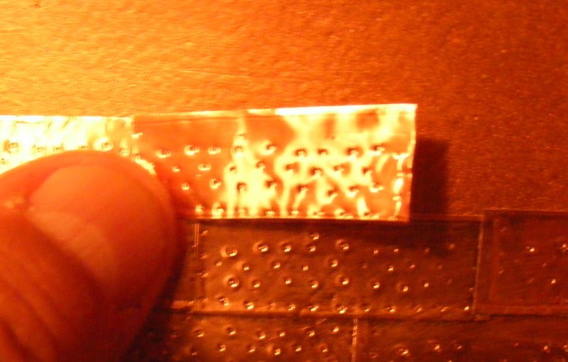
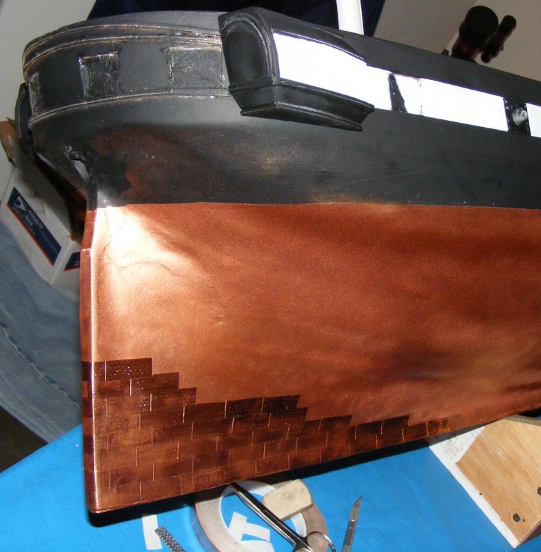
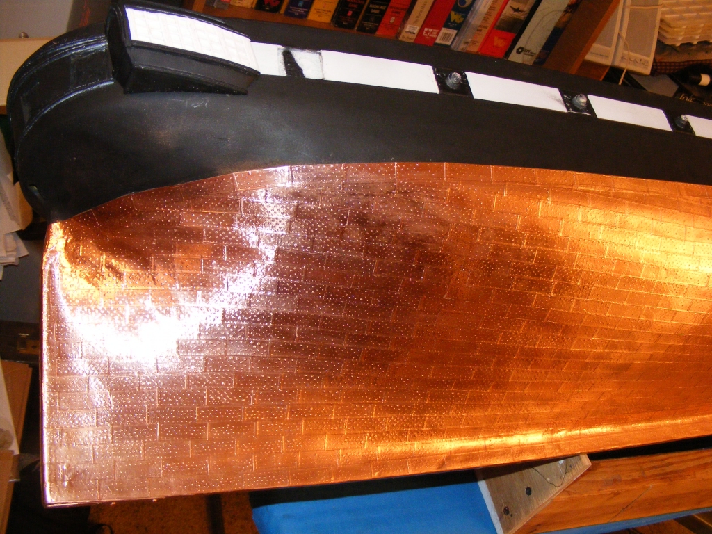
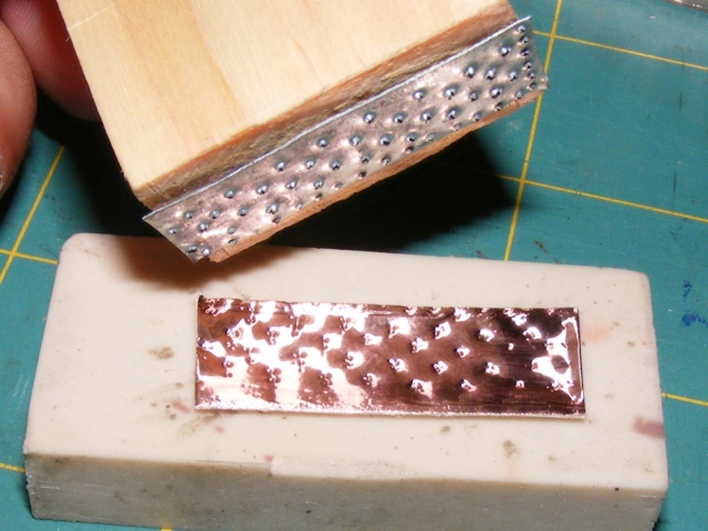
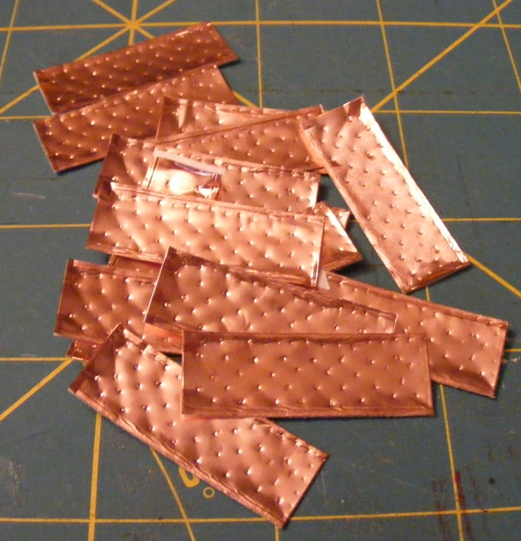
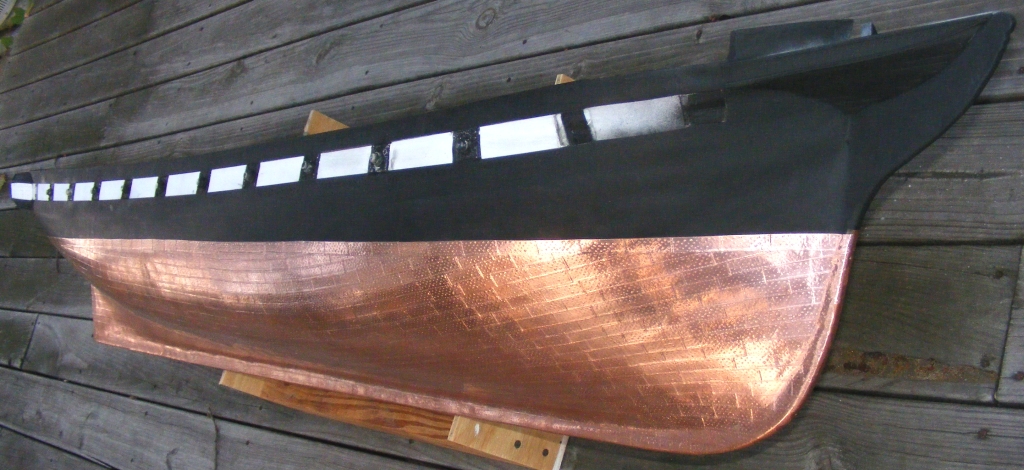
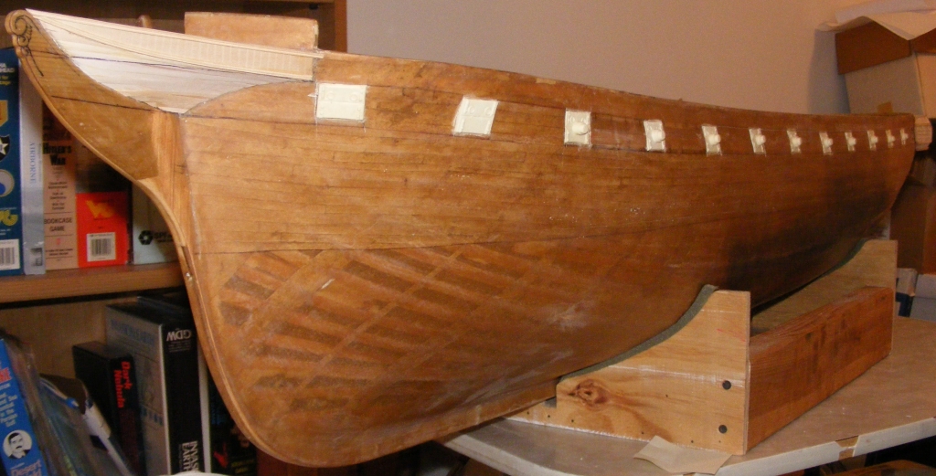
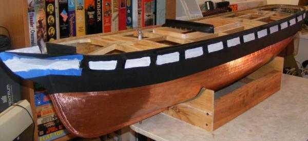
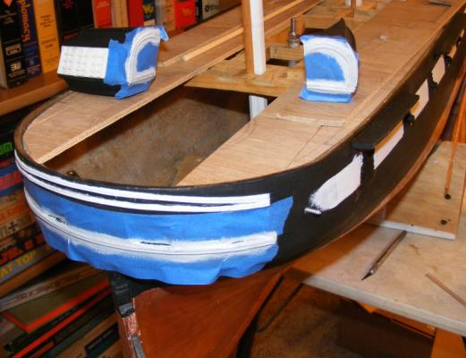
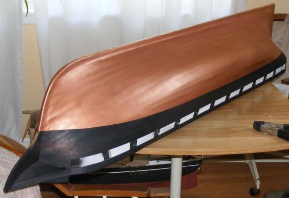
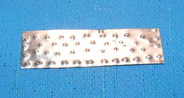
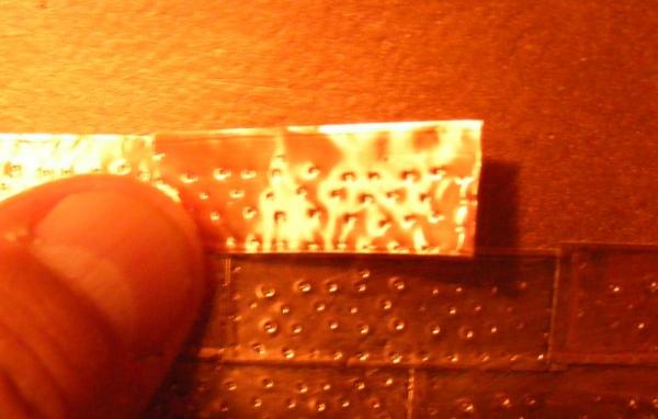
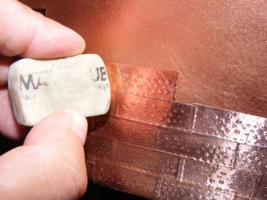
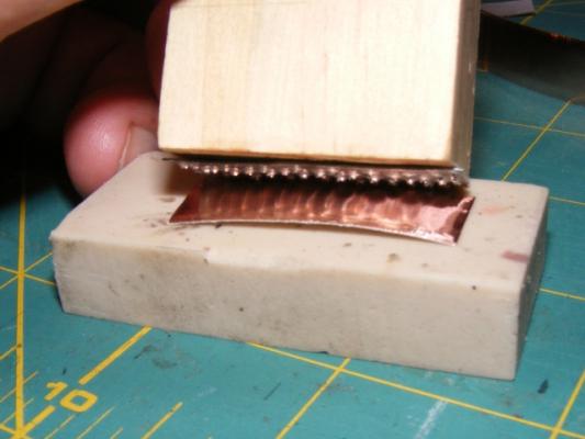
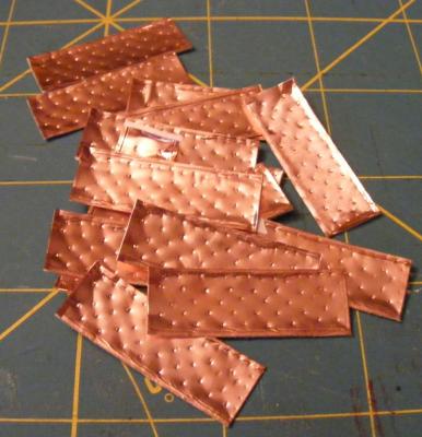
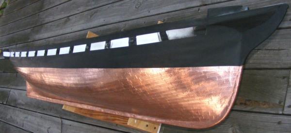
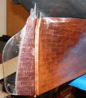
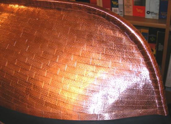
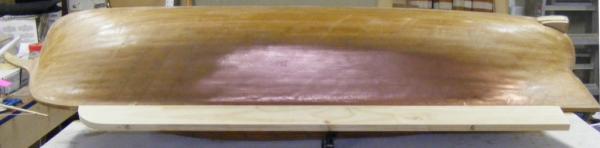
Paint! Painting the hull was more of a primer job than a finished surface. I had sprayed some Krylon black and some copper on the hull a while back to see how it held up to handling; that's what appears like a scorch mark on the hull during the float test. I sanded the hull and washed it with dish-washing detergent, then wiped it down with degreaser. I masked off the white stripe and sprayed it with flat white then, when it had set, masked over the stripe leaving the gunports uncovered, and masked the waterline about 1/2 and inch above the LWL - this is the top of the copper. The hull was then sprayed flat black. The bottom was sprayed with the copper and the quarter galleries were painted to match As I said, this wasn't meant to be a great paint job, but more of a primer coat, and she was looking a bit like a log to me. I painted the bottom copper with the idea that if any of the tape came off, it would expose the copper color, as opposed to black or white. From a log to a copper bottomed pot I got three rolls of the 1/2" wide copper tape. I calculated it would take two rolls to do the hull and got the third roll to be safe. I did wind up going a few inches into the third roll. The tape came from The Tape Depot and has an acrylic adhesive; just peel the paper off and stick it on. I don't recall now, but I think I got the "conductive" version. I made a pair of stamps from some sheet aluminum (one for port side plates, the other for starboard side plates), using a nail to create the protrusions. This was attached to a block of pine and pressed into the face of the tape against an eraser. Coppering is attached to the hull with nails that have countersunk heads, like a wood screw, into pre-punched holes. The effect is NOT the riveted appearance most modeler's apply, but more the opposite. The dents made in the copper are push back out when it's pressed onto the hull and gives more of a countersunk nail appearance. I pre-made 20 or 30 plates at a time, then began applying them. I began applying them from the keel at the rudder post, upward, and forward so each plate overlapped the ones below it and behind it about 1mm, like scales. Each plate was burnish with an eraser. I also used my finger, but wound up with a lot of little cuts from the edge of the tape. Examining photos of the ship in drydock at various points in her life, where I could see, it seemed she wasn't coppered in any specific pattern, but simply from the keel up and finished with a girdling belt at the waterline. That's the pattern I went with. The rudder was coppered as well, and when both sides were done, the keel got plated and the hull was complete. I'm pretty pleased with the effect of the coppering. At this scale I couldn't just ignore the nail marks, but I didn't want that ridiculous round headed rivet effect I see on models so often. I never actually counted them, but I imagine there's some 2400 plates on the hull, counting the rudder. After one side was done, I, and my fingers, needed a break from all the peel, stick, and rubbing - so I took a break by working on The Mast Tops


- 553 replies
-
- 6
-
-
- sloop of war
- constellation
- (and 3 more)
-
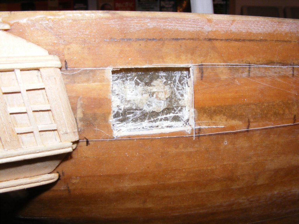
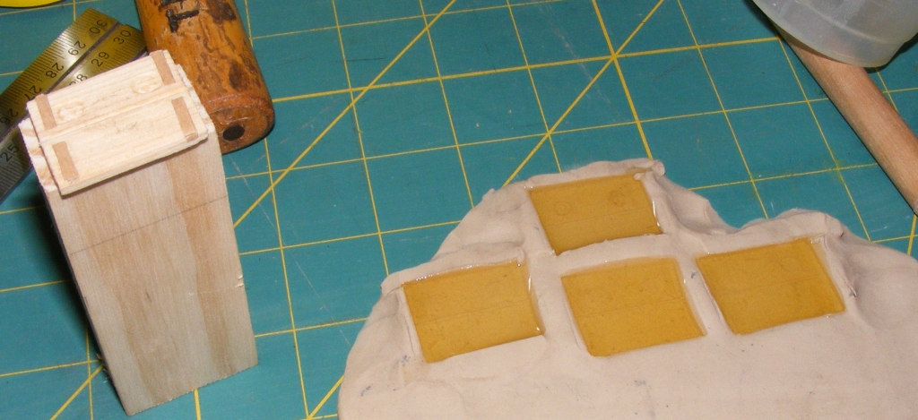
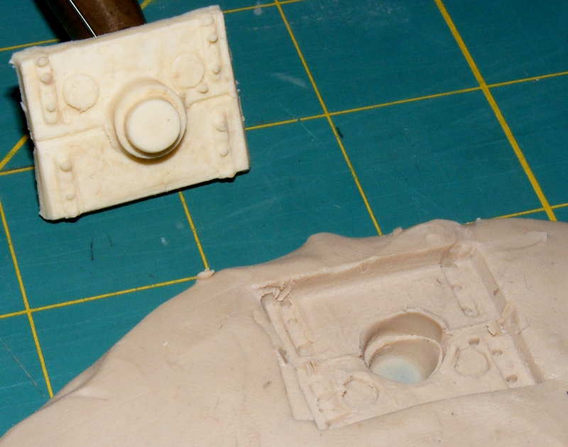
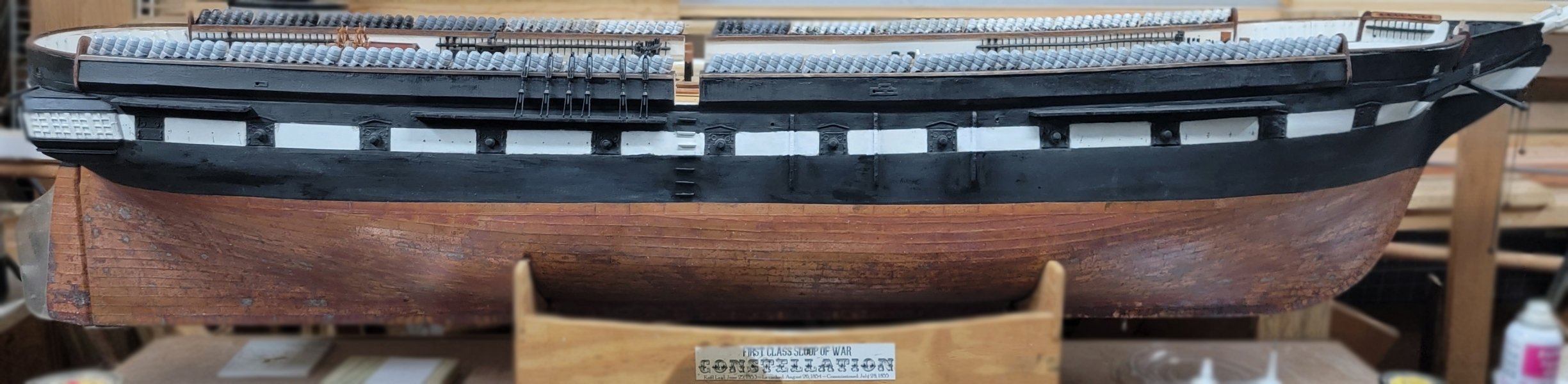
By Constellation's time, the split gunport was in common use, with a hole in the center to grasp the muzzle of the gun which poked through a short way and had a tampion in it. I decided not to model the gundeck to keep things simple and a bit more water resistant. I cut out each gunport, but only the outer glass and the resin/wood batten layer, leaving the mat layer inside. After a few tries, I managed to make a form that I was ok with and pressed it into some clay. This became a mold to make 20 lids with muzzles and 10 plain lids without muzzle holes. There would be three plain lids on each side and 4 on the stern. The stern lids would be cut and mounted in the open position later. Each lid was set in it's port with epoxy thickened with fine sawdust to act as a filler as well as a glue. I decided I was actually going to copper the bottom, and order a couple of rolls of peel-n-stick copper tape from The Tape Depot. That tape came in and I realized it was time to... Paint!


- 553 replies
-
- 3
-
-
- sloop of war
- constellation
- (and 3 more)
-
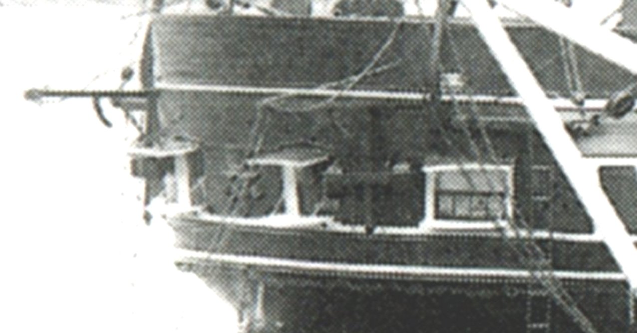
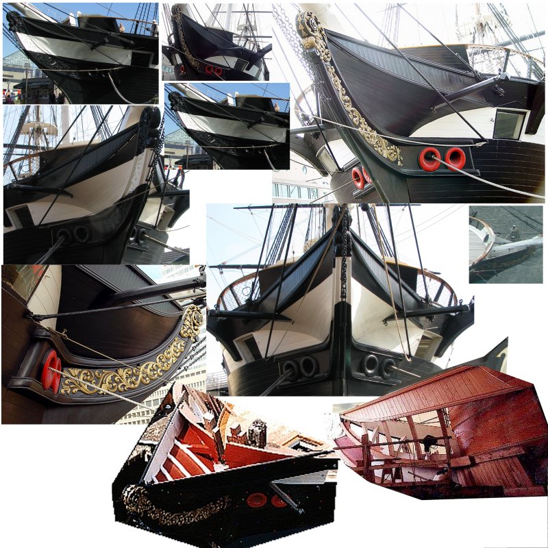
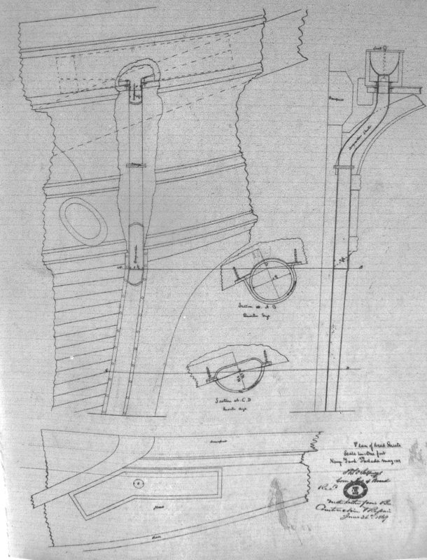
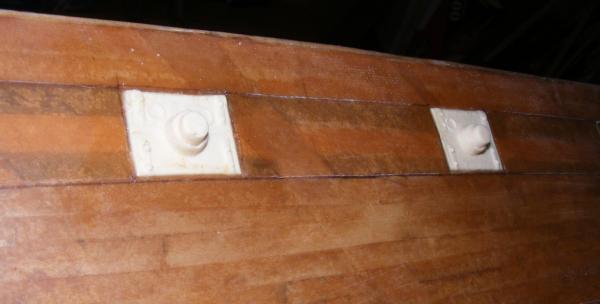
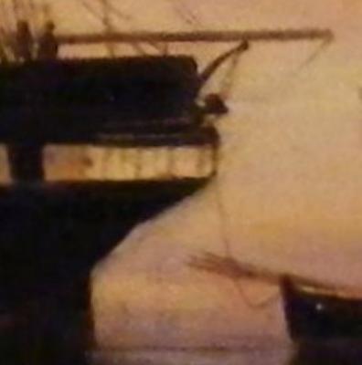
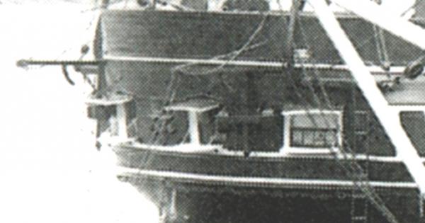
By-the-way, in that 1859 drawing of Constellation in drydock, I have no idea what those round objects are between the stern ports. I'll wager your first guess is port lights, but they are drawn 3-dimentional and the port side ones are shaped all wrong if they were ports. If fact, if they are protruding, then they appear to be pointed out-board from where they are; if they are inset, then they appear to be pointed directly aft. They also appear to be connected by a cross-bar with a vertical bar running through it, right where the boat davits are - which were iron and slightly curved, but I believe pivoted up and down on an upright bar that allowed it to also swing from side to side. I thought maybe these were some sort of fender to keep the boat from banging against the stern, but the boat would still hit at the center of the stern on the medallion? But they appear to be just that in the photo taken in the 1880's. So, what are they? I'm simply going to leave them off for now. If I can determine what they are for sure, I can add them at any time.
- 553 replies
-
- 2
-
-
- sloop of war
- constellation
- (and 3 more)
-
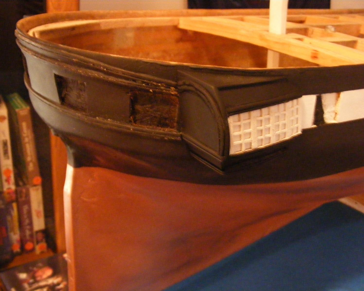
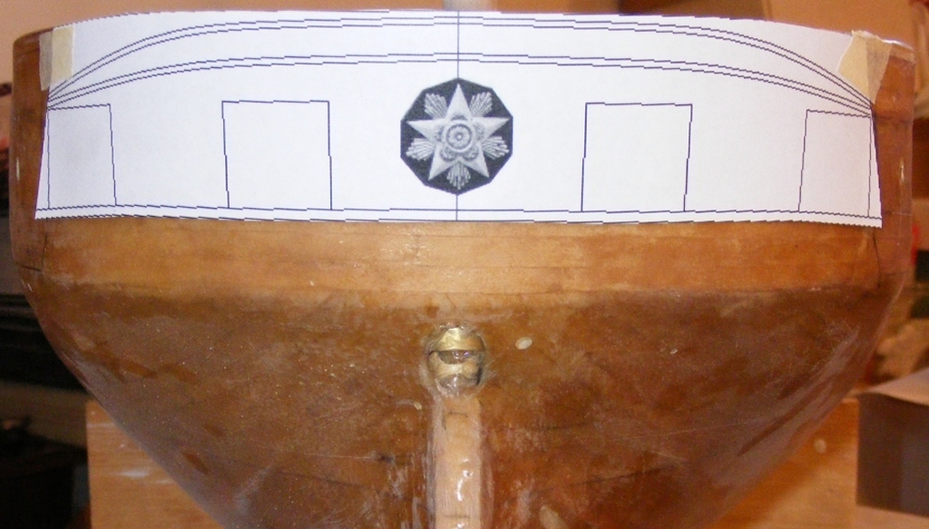
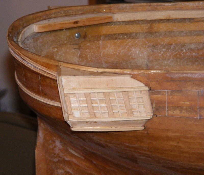
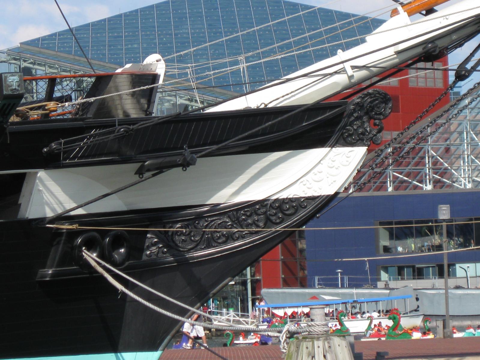
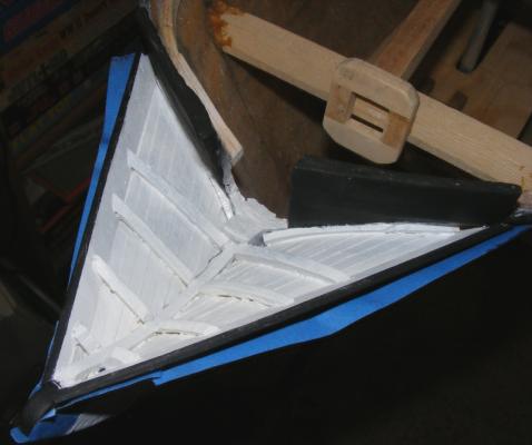
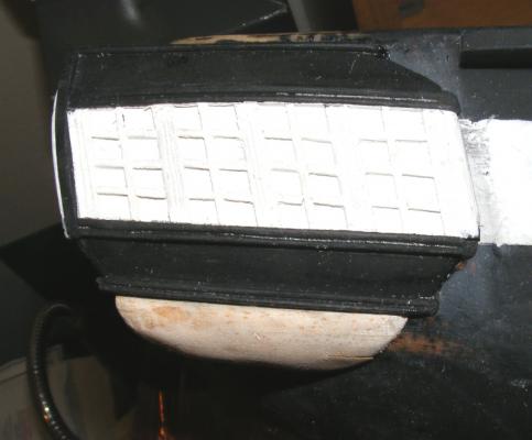
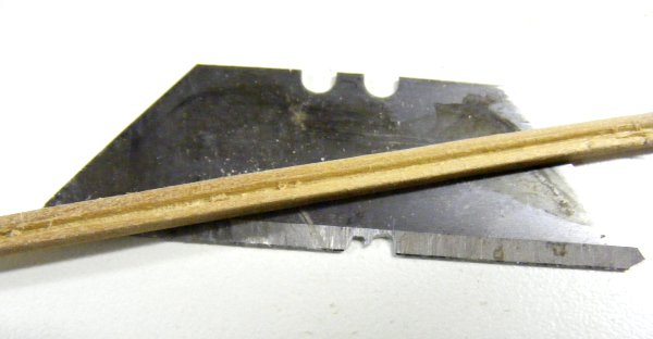
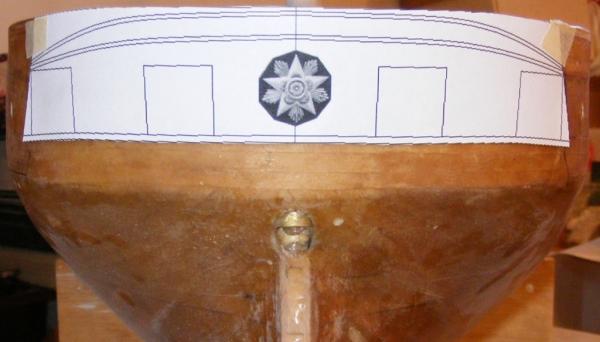
Now, we move aft... I only have one image of the stern of the ship that was done when she was in Boston for a refit in 1859, that shows how the stern appeared. It is really nothing like any image of her afterward in that the upper curved moldings disappear. Another painting of the ship at Naples in 1856 shows the stern somewhat, but I've never found a clearer image, nor one in color, where I could actually make out any detail other than the white stripe doesn't wrap around the stern. With that little ammunition in hand, I wrapped some paper around the stern and marked where things were; the backs of the quarter galleries, the bottom of the stern, the stern ports, etc, etc. Removing the paper, I connected the marks and basically drew the stern's details on the flat sheet. This I scanned so I could work on it in the computer; adding moldings, the medallions, and other details. Printing this and cutting it out, I used it to mark where everything went on the model itself. I used an old utility knife blade to make a molding scraper and proceeded to apply moldings with epoxy. The quarter galleries also got a dose of detailing, in the form of posts and window mullions.


- 553 replies
-
- 5
-
-
- sloop of war
- constellation
- (and 3 more)
-
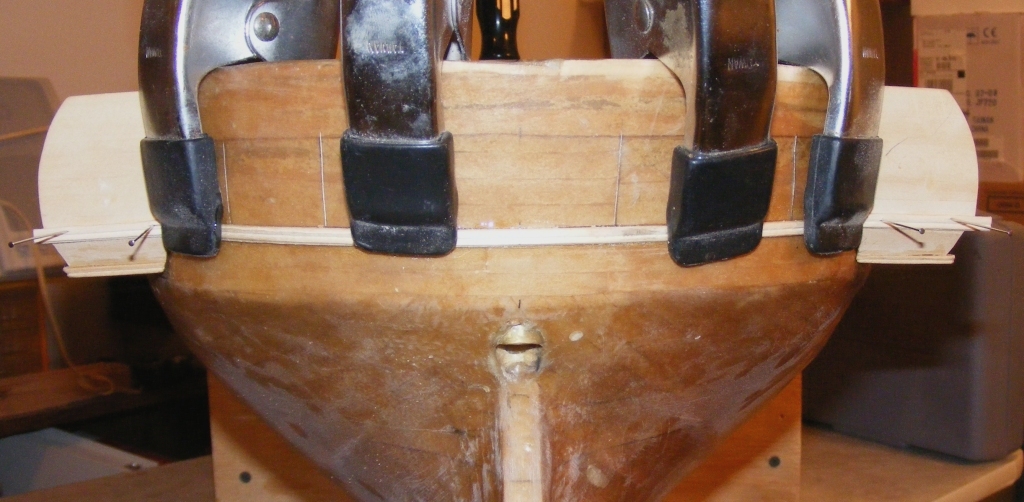
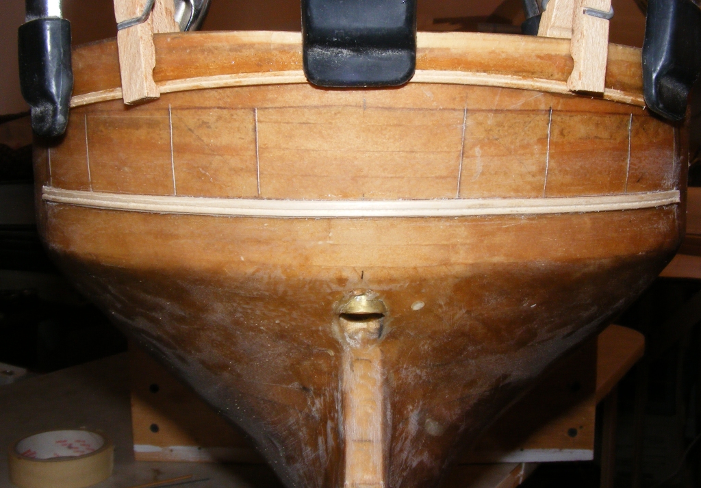
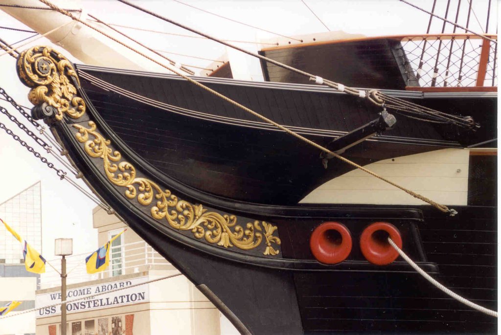
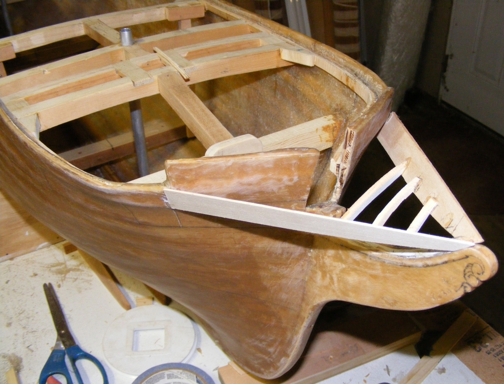
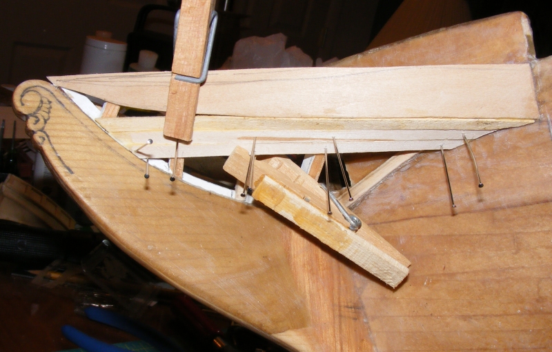
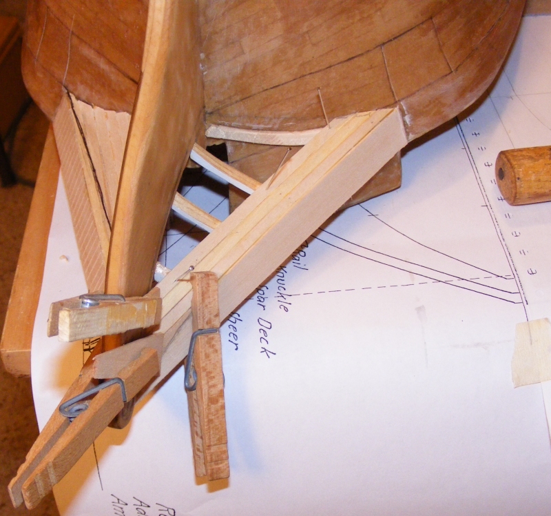
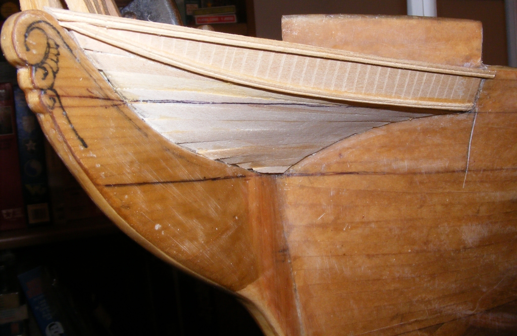
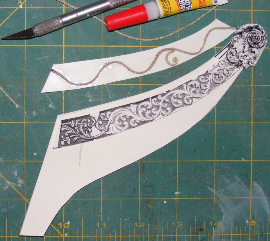
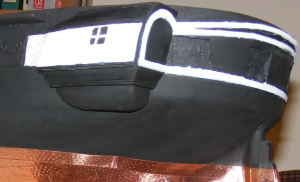
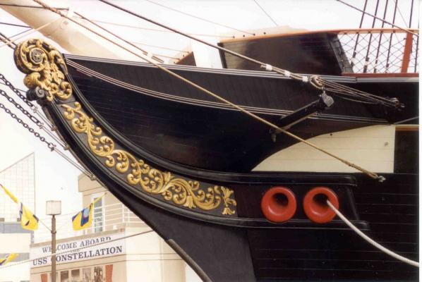
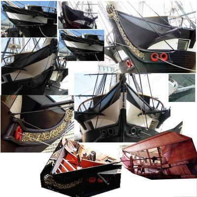
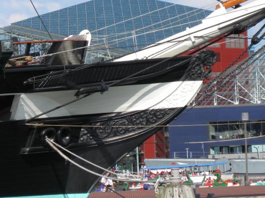
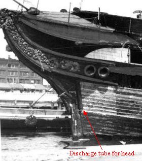
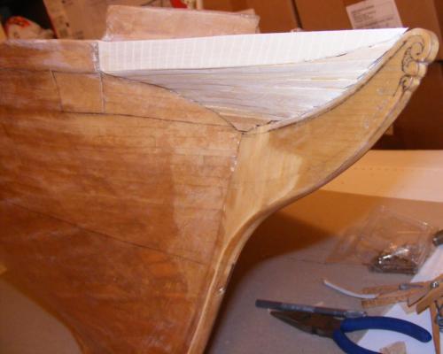
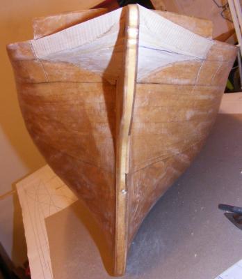
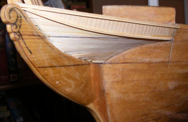
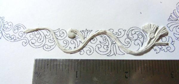
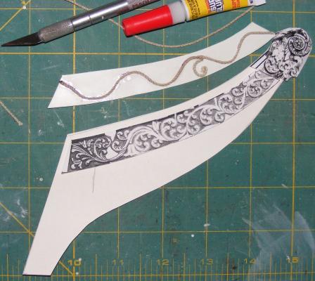
Constellation's head was always enclosed and from her launch till the 1880's she had a white stripe painted straight through the head, except maybe for a short time during her Mediterranean cruise during the Civil War when it's mentioned that she was painted all black for a short time. The model, will, of course, have an enclosed head and carvings, painted as she was in 1856. The detail of the carvings are beautiful and it's hard to imagine they were painted through the first 25 years of her life - Beyond the fiddle-head, I wonder why they put carvings on her trail boards at all. When the ship first returned from restoration, her bow carvings, all original to the ship, were done up in gold leaf. The ship is allegedly supposed to appear as she did during the Civil War, so the gun strip was painted through the head. There is, up here, a head; the "seats-of-ease" as it were, with a chute on either side of the bow to take the waste down to the waterline. This set-up was on the ship right until she came to Baltimore in the mid 1950's to be "restored" as a frigate. Replicating these carvings on the model is going to be quite the challenge. I tried using Sculpty clay and it could probably be done, but I wasn't getting anywhere with it. Someone suggested gluing string and cord to a trail board and painting it thickly. This didn't work out either. What I'd like to do is have a set photo-etched, in two layers on each side to get the detail. Further detail can be scribed and filed in, or added with Sculpty. We'll see where this ends up someday. As for enclosing the head on the model, I first had to figure out how it was done on the real ship. There's surprisingly little information on the actual structure of this enclosure beyond it's being simple "old-style" head rails wainscoted over. So, this is the approach I took... Using pine, I made a keel, of sorts, on top of the head knee, to catch the ends of the stanchions, or ribs. There are 5 ribs on the ship now, one of which is attached to the hull planking. The upper rails are just sheet bass scribed to represent wainscoting. The ribs are planked in straight runs on the restored ship, so I followed suite with more sheet bass. It all got a very thin coat of water-putty, and then a wash of diluted white glue to help seal everything up. Next up: The Stern


- 553 replies
-
- 3
-
-
- sloop of war
- constellation
- (and 3 more)
-
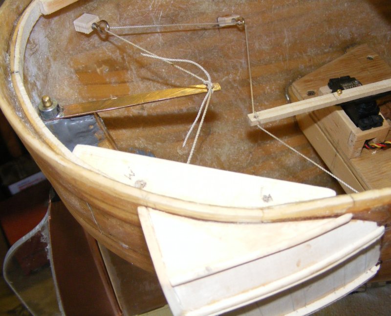
That's just the stock servo Bob, I hadn't gotten that far along in the design for handling the heads'ls. On my Pride of Baltimore I have two heads'ls, an overlapping fores'l, running backstays, and running main fore stays to handle - if I can figure out a way to deal with all that - every other model will be a walk in the park. I've got a couple of ideas in mind that I need to mock up and test - the one I'm hoping will work will use a large cross-arm on the servo and also slack the sheet before pulling it across. I'd rather not use a winch if I can stay away from it. I haven't gotten to it yet, but the tensioning system for the braces is being changed as well; to a setup where the winch servo itself slides fore-n-aft against springs instead of the brace being pulled against a spring.
- 553 replies
-
- 1
-
-
- sloop of war
- constellation
- (and 3 more)
-
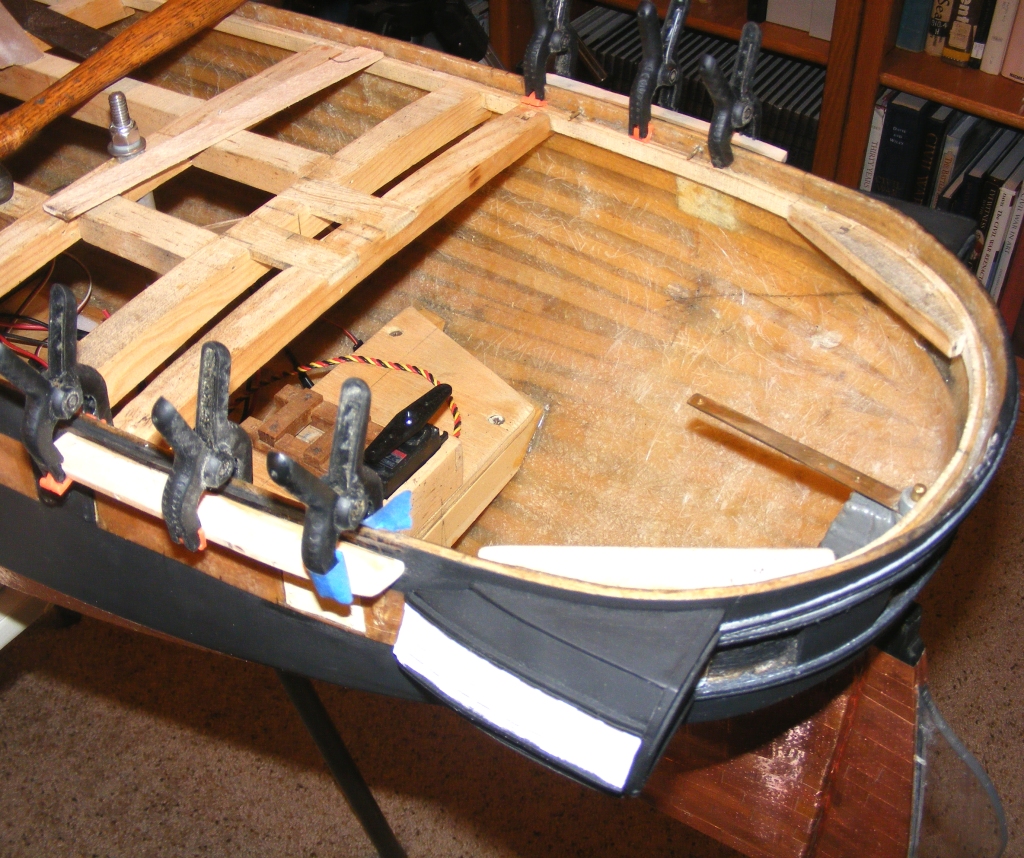
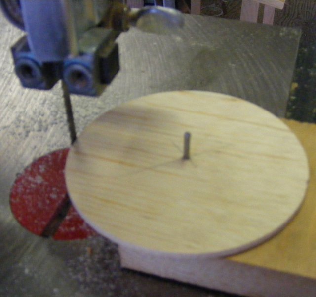
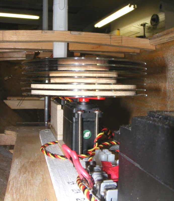
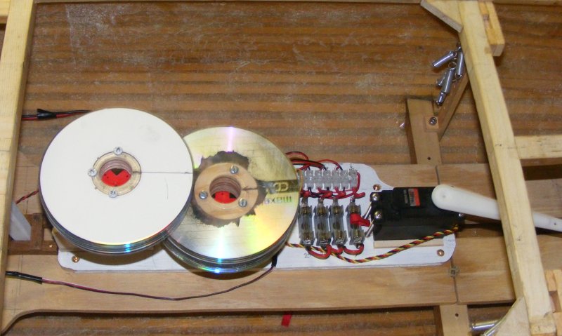
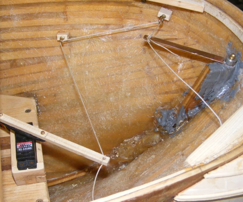
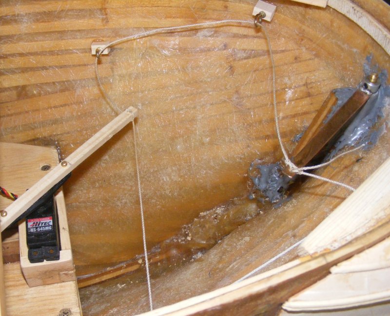
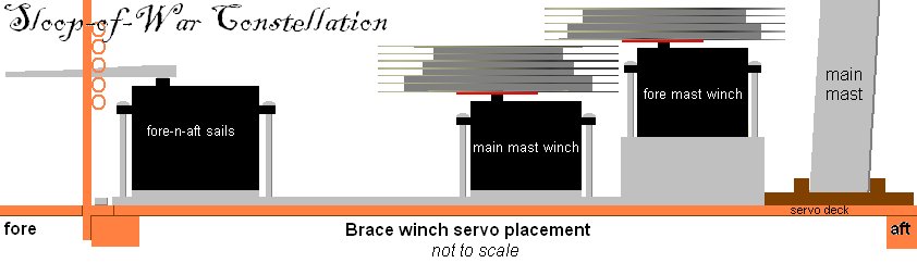
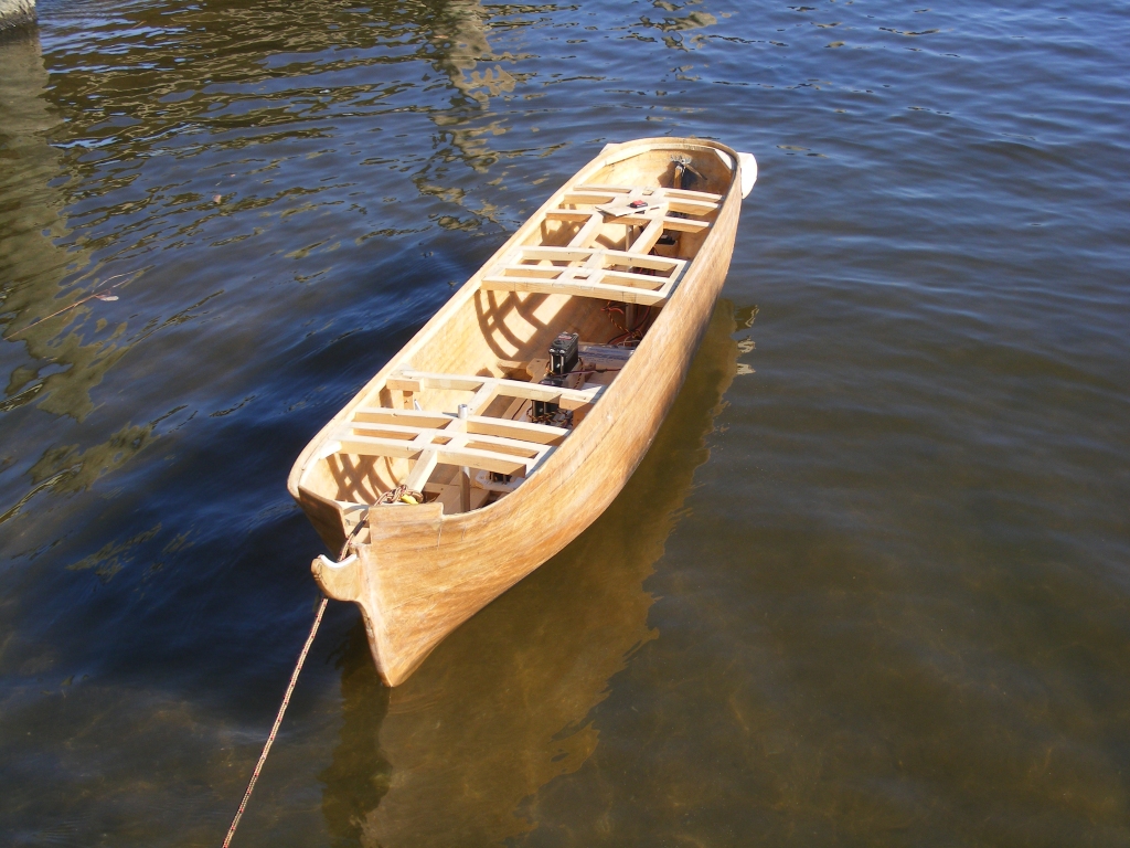
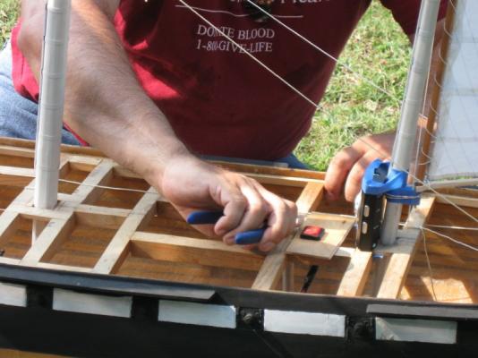
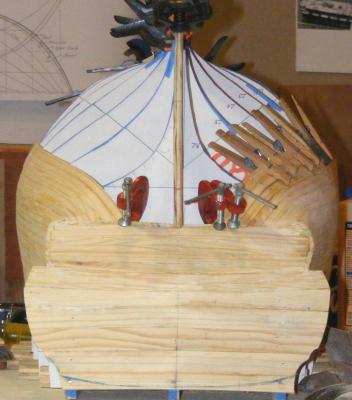
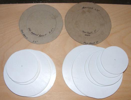
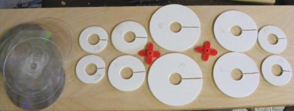
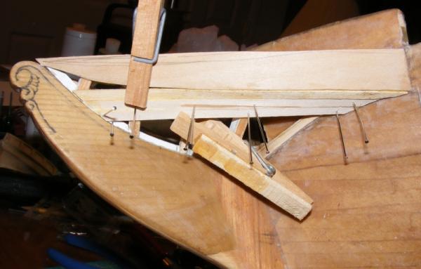
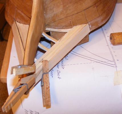
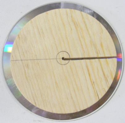
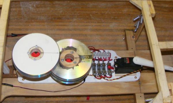
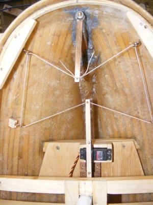
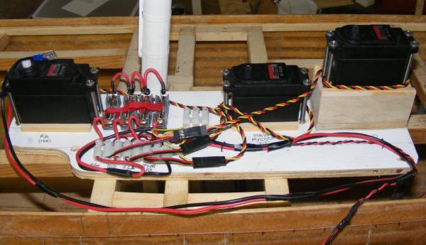
Brace Winches The winch drums were cut from pine planed down to 1/8 inch thick. Each pair of drums was the diameter determined for it's yard and each had a slot cut in it so the brace could be threaded and knoted inside the drum. Each drum was separated by a flange made from compact discs, CDs. When the drum was assembled, a 1 inch hole was bored in it's center, and a servo horn was mounted at the bottom of the assembly. The forward drum (right) is the main & mizzen mast winch; from the bottom up, in pairs, are the main-corse, crossjack, and main-tops'l. The aft drum is the foremast winch with the fore-corse and fore-tops'l braces. To the right top of the winches in the photo you can see some silver colored cylinders; those are the springs that will maintain tension on the braces. There are 5 on each side. The large servo at the right of the photo will control the fore-n-aft sails; heads'ls, spanker, etc. Steering The rudder head is very close the to stern of the ship, just as the real one is; so I don't have the space to mount a T type servo arm with hard push-pull linkages to steer the model. Instead, I mounted a tiller on the rudder and will mount beams with blocks to route the tiller rope to the steering servo; a high-torque, metal geared type. In the images you'll see some cup-hooks in wood blocks hot-glued to the hull to test the theory. Beams will be epoxied in place and the tiller rope guides will be mounted on them, that way it won't pull off the the hull. With the servo hard-a-port, and hard-a-starboard.


- 553 replies
-
- 9
-
-
- sloop of war
- constellation
- (and 3 more)
-
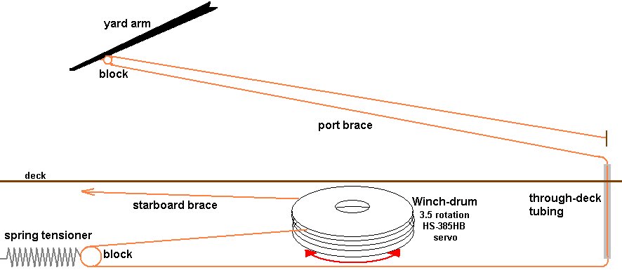
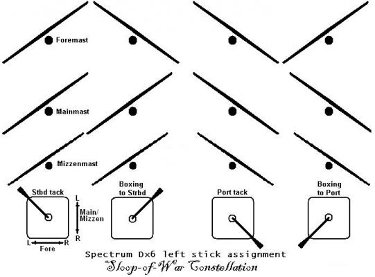
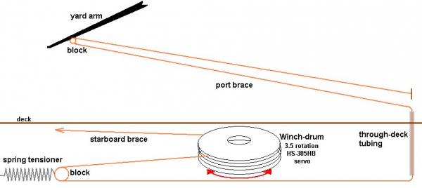
Setting up a model square rigger to actually sail by remote control isn't especially difficult, unless you're trying to maintain a scale appearance - then it becomes a challenge. There's two major geometry issues to deal with; the yard braces, and any sails that overlap each other or a stay, such as the heads'ls. The usual way of dealing with bracing the yards is to put the widest set of arms on the brace control servo that will fit in the hull. The braces are run up to the yards and attached the same distance out from the center line on the yard as they are out from the center of the servo arm. This basically forms a parallelogram where everything moves evenly. The problem is, this isn't how the braces run on a real ship; they are run out almost at the end of the yard, out-board of the side of the hull. The best way to deal with this is to use a winch on a servo designed to rotate multiple times, a winch servo. I intend to directly control the braces for the fore and main course yards, the crossjack, and the fore and main tops'l yards. The other yards will be pulled along by the sails below them. I also intend to control the fore mast braces separately from the main and mizzen masts so I can back the fore when tacking ship. <=- The braces will be controlled by the left stick on the radio transmitter. This means I need two winch drums for each controlled yard for a total of 4 for the foremast and 6 for the main and mizzen. The problem is, again, geometry. The fore course yard is longer than the fore tops'l yard (measuring between the points where the braces attach. The winch rotates 3.5 times. If the drum were the same size for each yard the braces would be pulled more for the shorter yards than for the longer ones - I want them all to come around evenly together. The simple answer is different sized drums for each yard, but nothing is ever simple. When the yards are squared across the hull, the braces are at their tightest. As the yard is pulled to one side, the opposite brace is fed off the winch at the same rate and goes slack. Bracing the other way the braces both go taught as the yard squares, then the paying out brace goes slack. Slack lines on a remotely controlled model are not good. They tend to snag and catch on things, and the brace paying out could actually run off the drum and tangle. To deal with this I intended to run each brace through a block (pulley) on a spring that would keep tension on each brace all the time. Initially I also planned to put some bungee else where in the circuit to be sure, but in the end I felt only the springs were needed. The winches would be mounted on a pallet that would fasten to the mechanical deck in the model, so the entire control system could be removed as a unit if required. They would also be offset vetically so they wouldn't interfere with each other. More on braces and rudder control next:


- 553 replies
-
- 5
-
-
- sloop of war
- constellation
- (and 3 more)
-
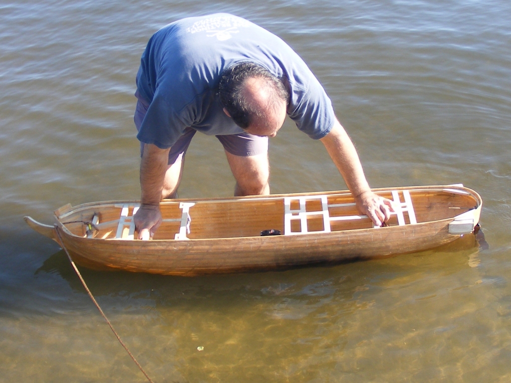
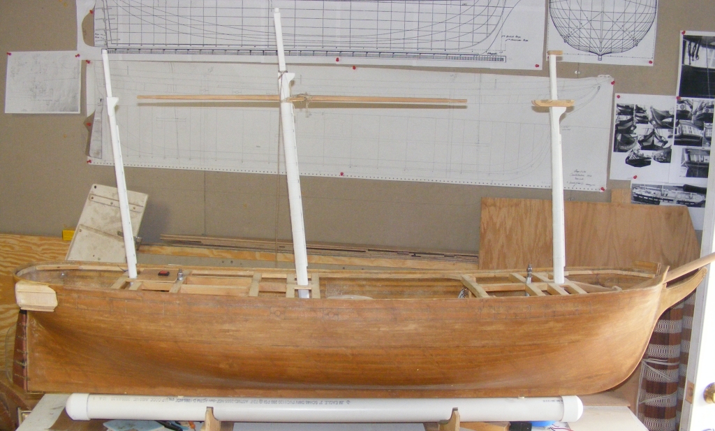
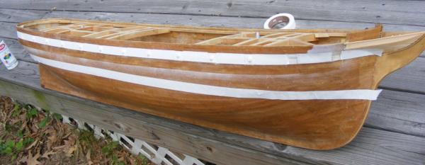
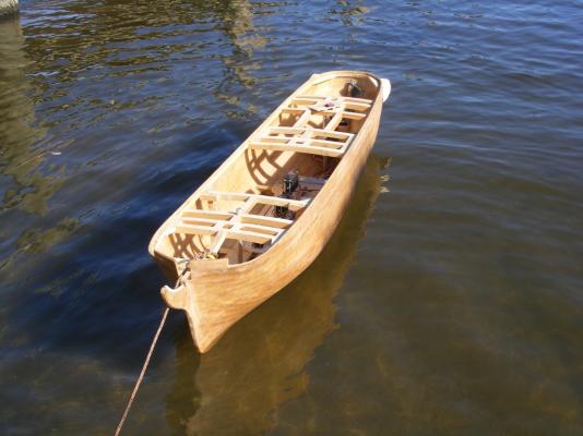
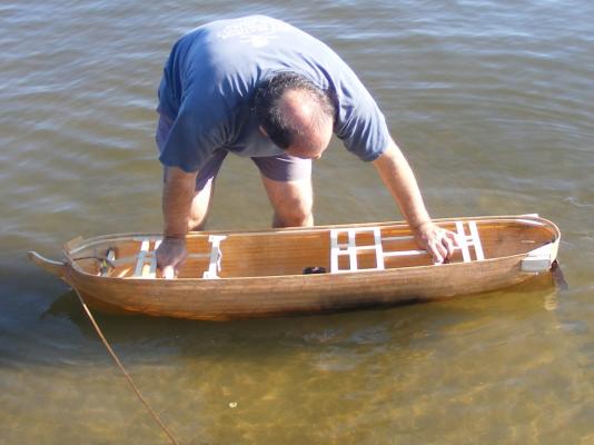
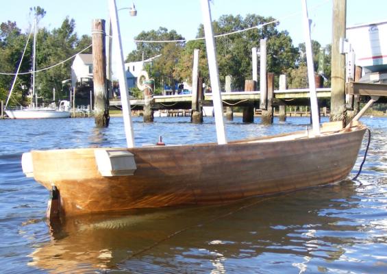
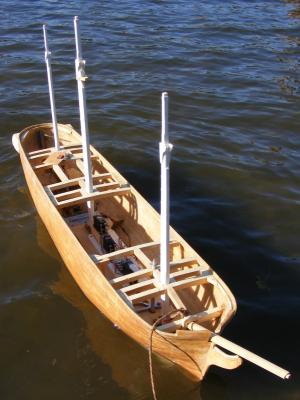
Funny you should mention that lambsbk, as it was about this time the model got wet for the first time On October 4th 2009, I had taken my daysailer Lydia out and tossed Constellation in the truck. When we got back I put the hull in the water for it's first float. I forgot the rods that held the ballast on, so the closest thing that might be deemed a test was when I pushed the hull down to it's waterline. No leaks. On the 7th, wanting a better "test" I tossed her in the truck and took her to the end of my street to Sloop Cove - where else do you float a sloop of war, eh? In total there was 50 pounds of lead on board; 42 in the torpedo, the rest in baggies placed in the hull. There was also about 4 pounds more consisting of battery, radio gear, and a couple of hand tools; plus her lower masts, which together don't weight half a pound. She floated 2 inches above her load waterline. I figure it'll take 12-15 pounds of internal ballast to get her down to waterline, that includes her running gear and battery. Next up: Radio Control
- 553 replies
-
- 11
-
-
- sloop of war
- constellation
- (and 3 more)
-
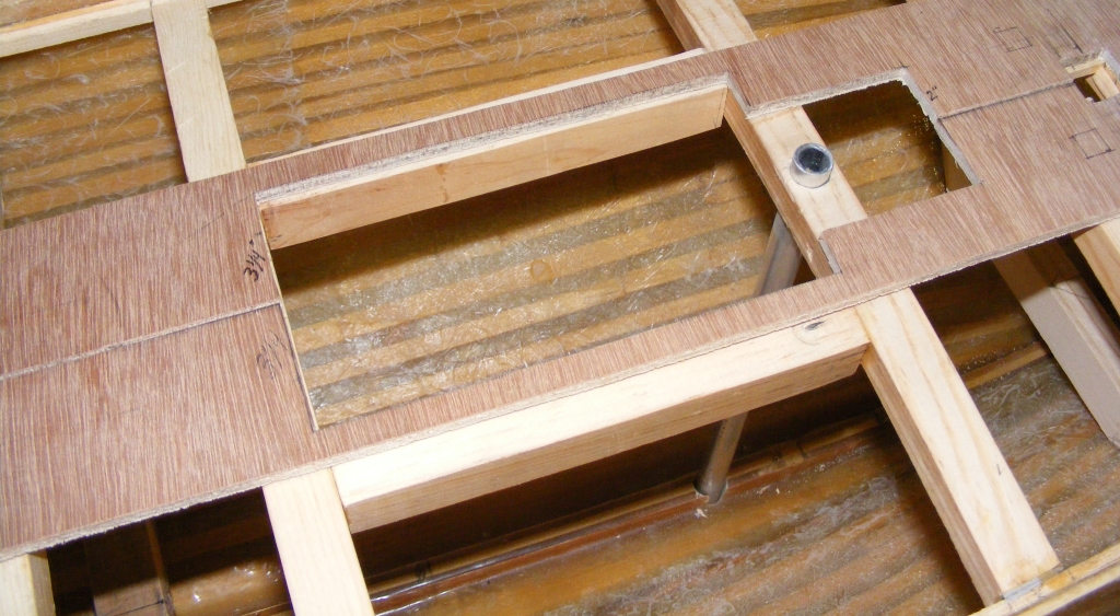
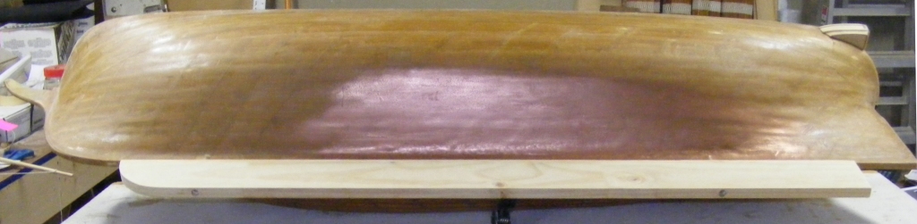
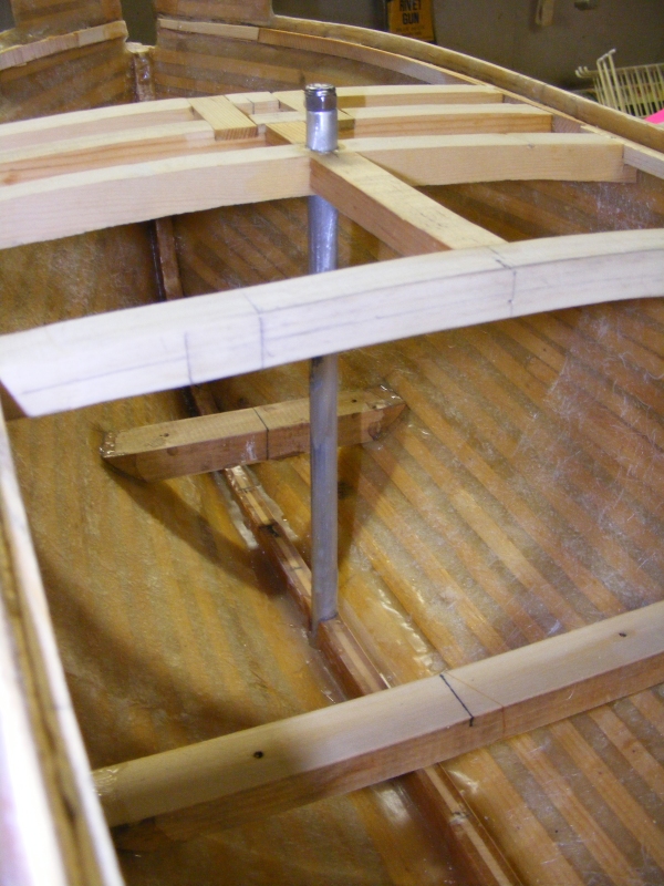
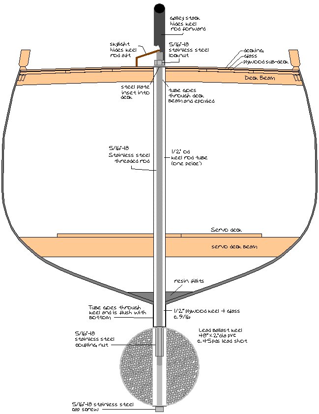
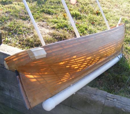
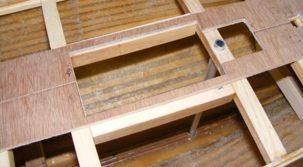
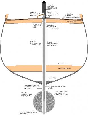
The next step was the removable ballast keel... The ballast would attach to the hull by means of two stainless steel threaded rods that would run through a pair of tubes from the spar deck, through the keel. The forward rod would be disguised with the galley stack, the after one hidden by the skylight that was part of the model's battery hatch made up of the skylight, companionway hatches, and the capstan. Initially I wanted to cast a flat lead bar about 3/4" thick that would bolt onto the keel and weight about 50 pounds, I made a wood mockup but I've never casted that much lead before, so I opted to fill a 2" PVC pipe with lead shot that weights in at about 42 pounds. The model will still require some internal ballast, which will be in the form of lead filled "bean-bags" that will attach with Velcro tabs, like the battery. Then it can be moved to trim the model as needed.

- 553 replies
-
- 7
-
-
- sloop of war
- constellation
- (and 3 more)