
JerryTodd
-
Posts
879 -
Joined
-
Last visited
Content Type
Profiles
Forums
Gallery
Events
Everything posted by JerryTodd
-
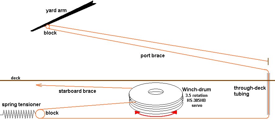
 That's just the stock servo Bob, I hadn't gotten that far along in the design for handling the heads'ls. On my Pride of Baltimore I have two heads'ls, an overlapping fores'l, running backstays, and running main fore stays to handle - if I can figure out a way to deal with all that - every other model will be a walk in the park. I've got a couple of ideas in mind that I need to mock up and test - the one I'm hoping will work will use a large cross-arm on the servo and also slack the sheet before pulling it across. I'd rather not use a winch if I can stay away from it. I haven't gotten to it yet, but the tensioning system for the braces is being changed as well; to a setup where the winch servo itself slides fore-n-aft against springs instead of the brace being pulled against a spring.
- 553 replies
-
- 1
-

-
- sloop of war
- constellation
- (and 3 more)
-
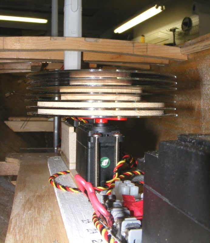
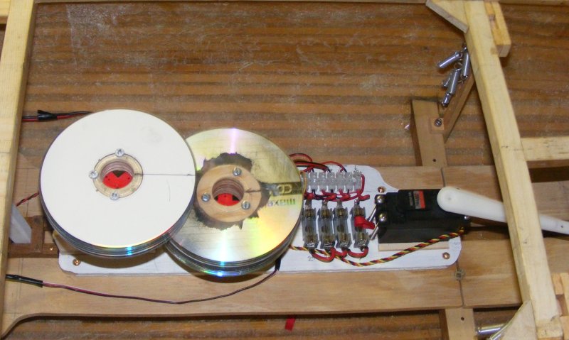
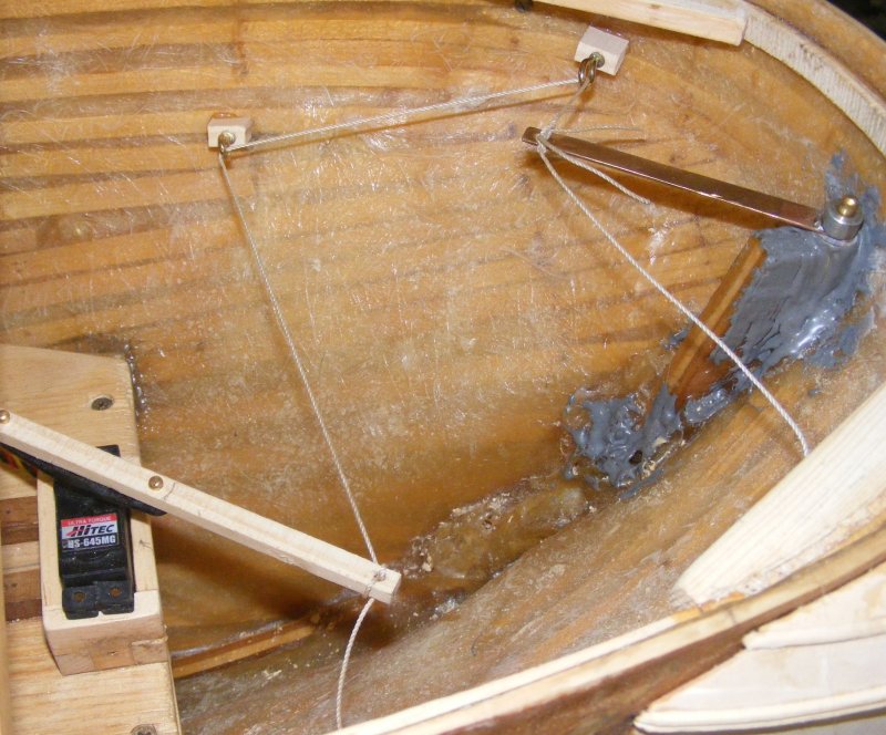
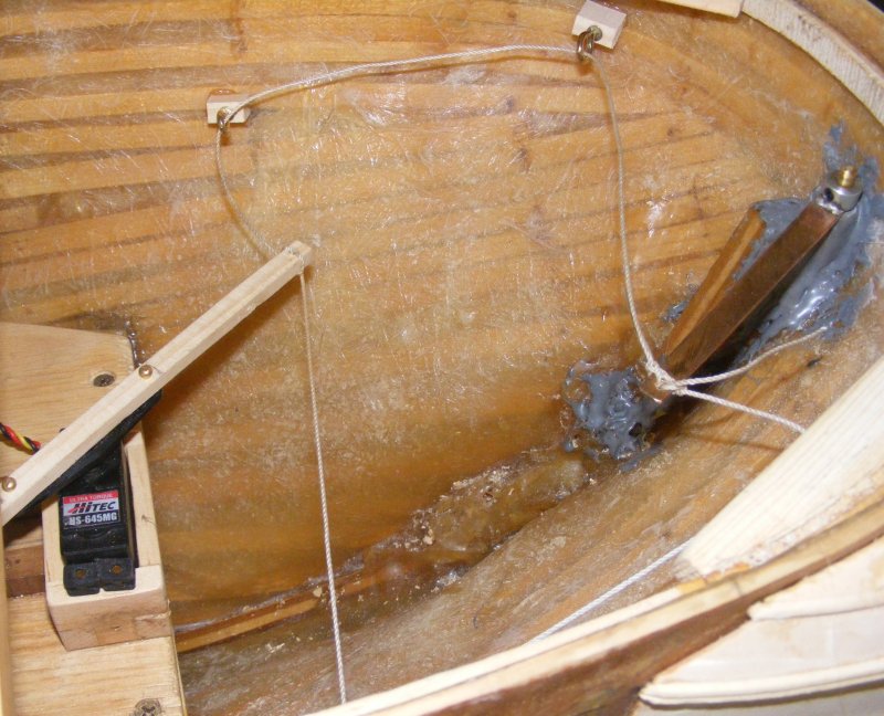
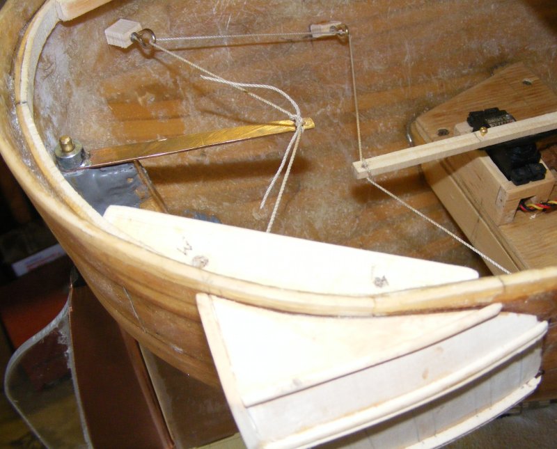
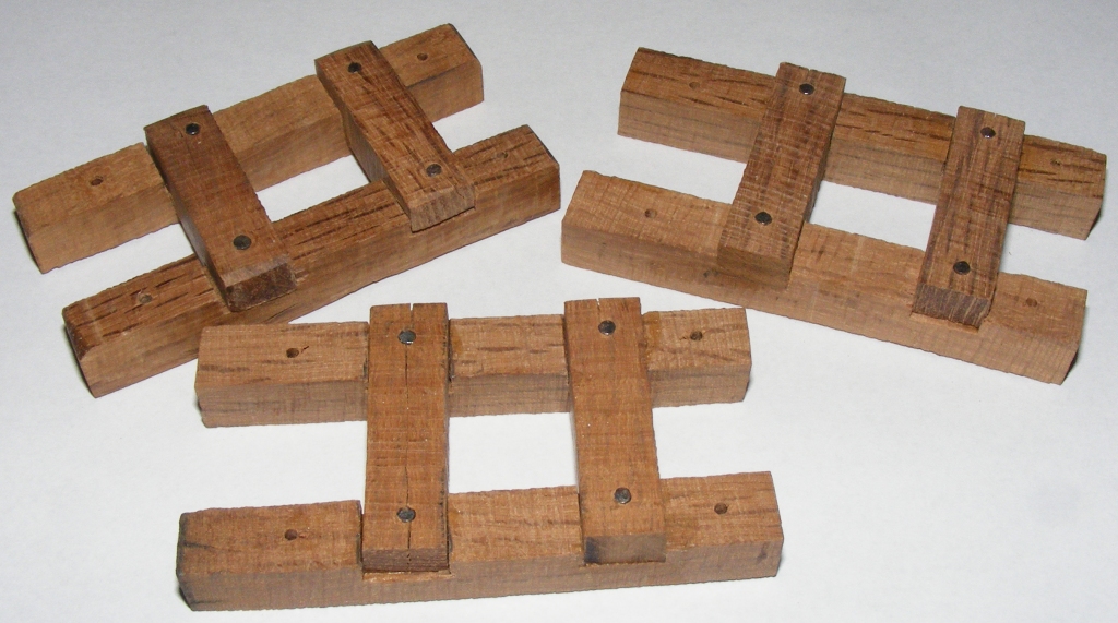
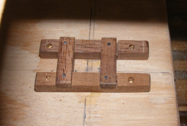
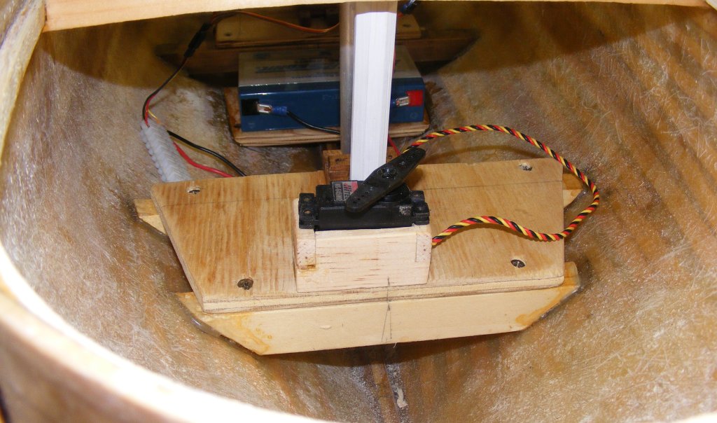
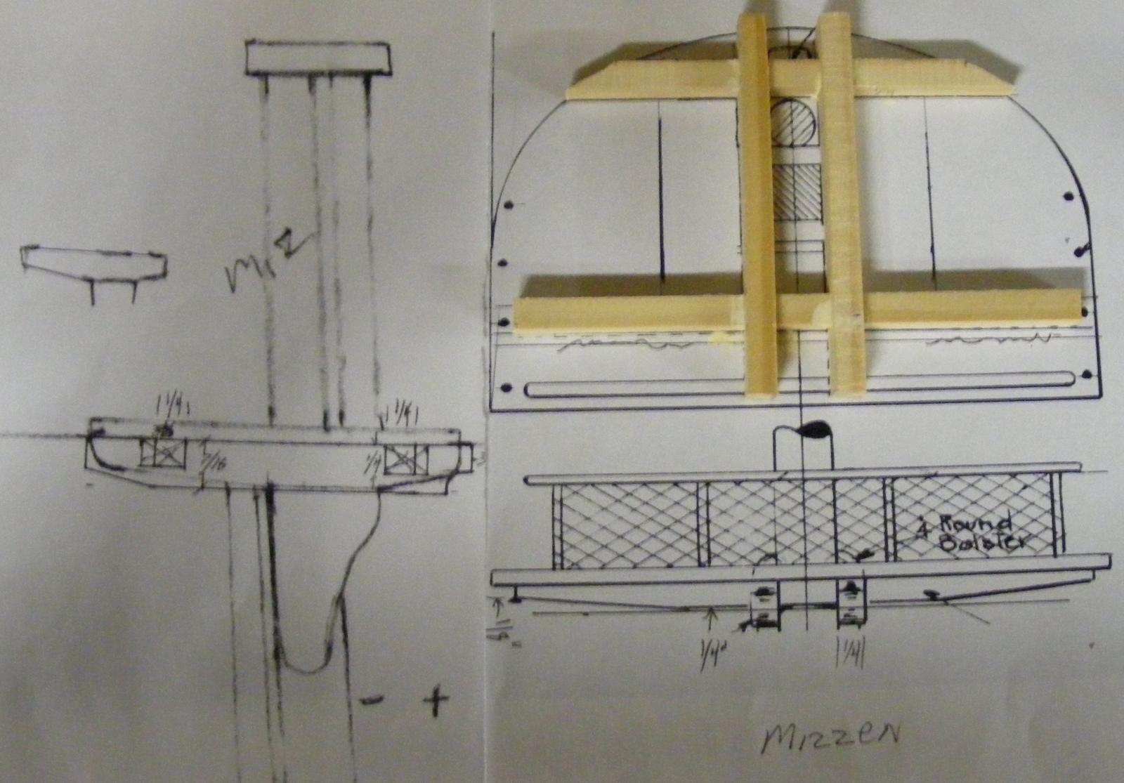
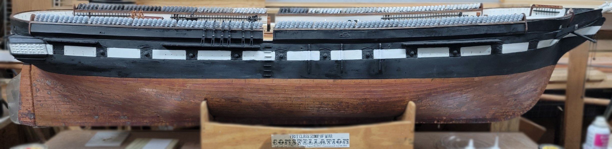
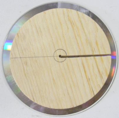
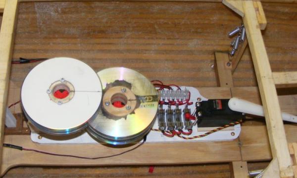
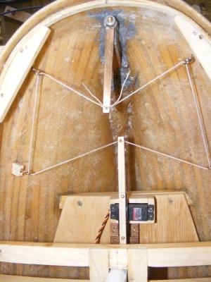
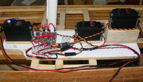
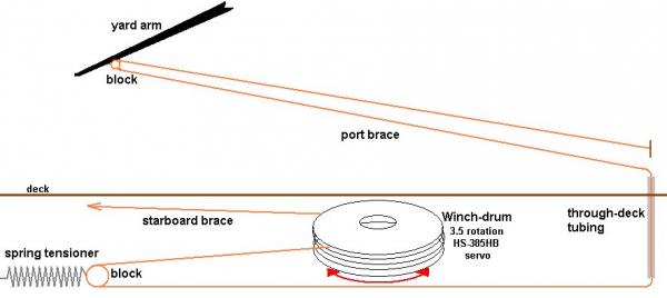
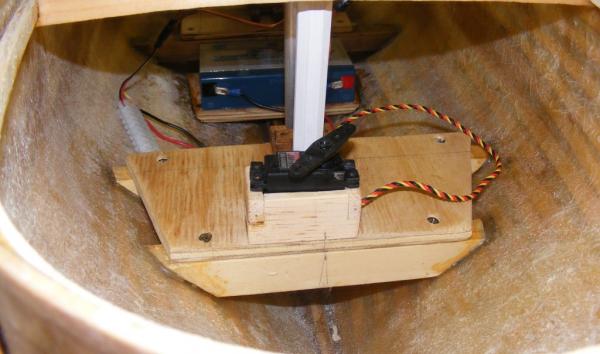
Brace Winches The winch drums were cut from pine planed down to 1/8 inch thick. Each pair of drums was the diameter determined for it's yard and each had a slot cut in it so the brace could be threaded and knoted inside the drum. Each drum was separated by a flange made from compact discs, CDs. When the drum was assembled, a 1 inch hole was bored in it's center, and a servo horn was mounted at the bottom of the assembly. The forward drum (right) is the main & mizzen mast winch; from the bottom up, in pairs, are the main-corse, crossjack, and main-tops'l. The aft drum is the foremast winch with the fore-corse and fore-tops'l braces. To the right top of the winches in the photo you can see some silver colored cylinders; those are the springs that will maintain tension on the braces. There are 5 on each side. Blocks will have to be made or aquired for the braces to run through. The large servo at the right of the photo will control the fore-n-aft sails; heads'ls, spanker, etc. Steering The rudder head is very close the to stern of the ship, just as the real one is; so I don't have the space to mount a T type servo arm with hard push-pull linkages to steer the model. Instead, I mounted a tiller on the rudder and will mount beams with blocks to route the tiller rope to the steering servo; a high-torque, metal geared type. In the images you'll see some cup-hooks in wood blocks hot-glued to the hull to test the theory. Beams will be epoxied in place and the tiller rope guides will be mounted on them, that way it won't pull off the the hull. This is actually very close to how the actual ship is steered. With the servo hard-a-port, and hard-a-starboard.


- 553 replies
-
- 9
-
-
- sloop of war
- constellation
- (and 3 more)
-
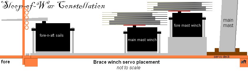
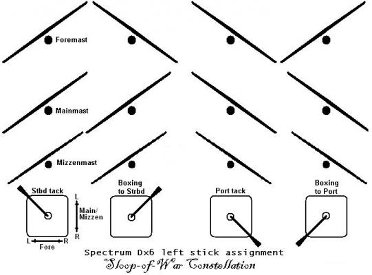
Setting up a model square rigger to actually sail by remote control isn't especially difficult, unless you're trying to maintain a scale appearance - then it becomes a challenge. There's two major geometry issues to deal with; the yard braces, and any sails that overlap each other or a stay, such as the heads'ls. The usual way of dealing with bracing the yards is to put the widest set of arms on the brace control servo that will fit in the hull. The braces are run up to the yards and attached the same distance out from the center line on the yard as they are out from the center of the servo arm. This basically forms a parallelogram where everything moves evenly. The problem is, this isn't how the braces run on a real ship; they are run out almost at the end of the yard, out-board of the side of the hull. The best way to deal with this is to use a winch on a servo designed to rotate multiple times, a winch servo. I intend to directly control the braces for the fore and main course yards, the crossjack, and the fore and main tops'l yards. The other yards will be pulled along by the sails below them. I also intend to control the fore mast braces separately from the main and mizzen masts so I can back the fore when tacking ship. <=- The braces will be controlled by the left stick on the radio transmitter. This means I need two winch drums for each controlled yard for a total of 4 for the foremast and 6 for the main and mizzen. The problem is, again, geometry. The fore course yard is longer than the fore tops'l yard (measuring between the points where the braces attach. The winch rotates 3.5 times. If the drum were the same size for each yard the braces would be pulled more for the shorter yards than for the longer ones - I want them all to come around evenly together. The simple answer is different sized drums for each yard, but nothing is ever simple. When the yards are squared across the hull, the braces are at their tightest. As the yard is pulled to one side, the opposite brace is fed off the winch at the same rate and goes slack. Bracing the other way the braces both go taught as the yard squares, then the paying out brace goes slack. Slack lines on a remotely controlled model are not good. They tend to snag and catch on things, and the brace paying out could actually run off the drum and tangle. To deal with this I intended to run each brace through a block (pulley) on a spring that would keep tension on each brace all the time. Initially I also planned to put some bungee else where in the circuit to be sure, but in the end I felt only the springs were needed. The winches would be mounted on a pallet that would fasten to the mechanical deck in the model, so the entire control system could be removed as a unit if required. They would also be offset vetically so they wouldn't interfere with each other. More on braces and rudder control next:


- 553 replies
-
- 5
-
-
- sloop of war
- constellation
- (and 3 more)
-
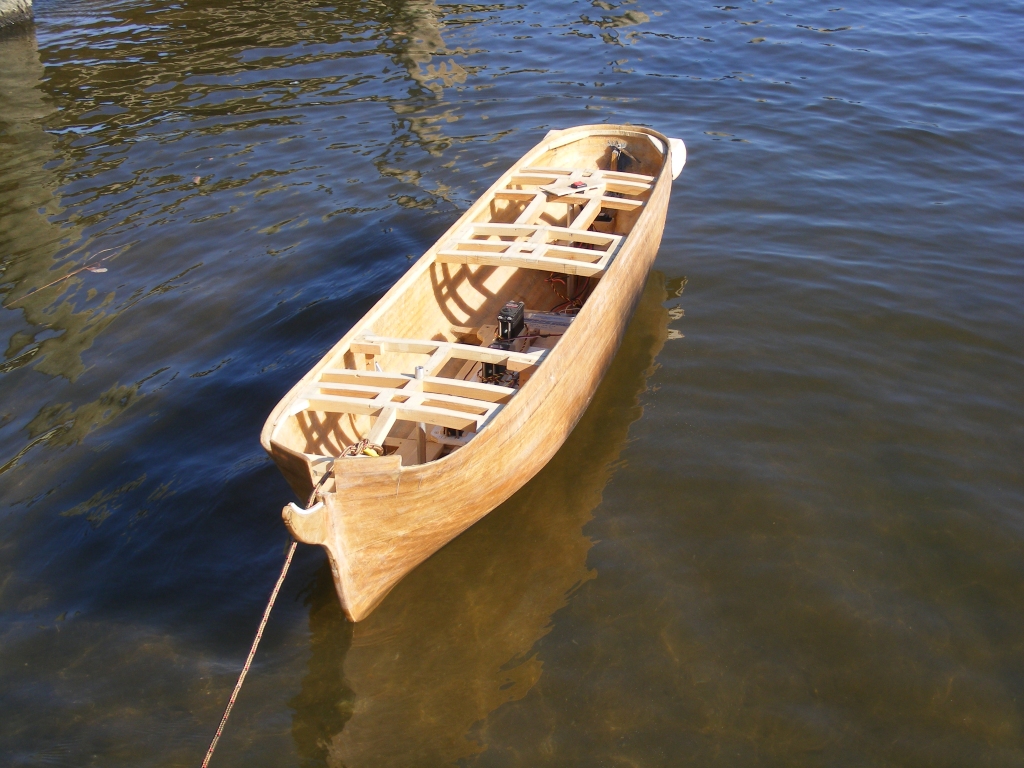
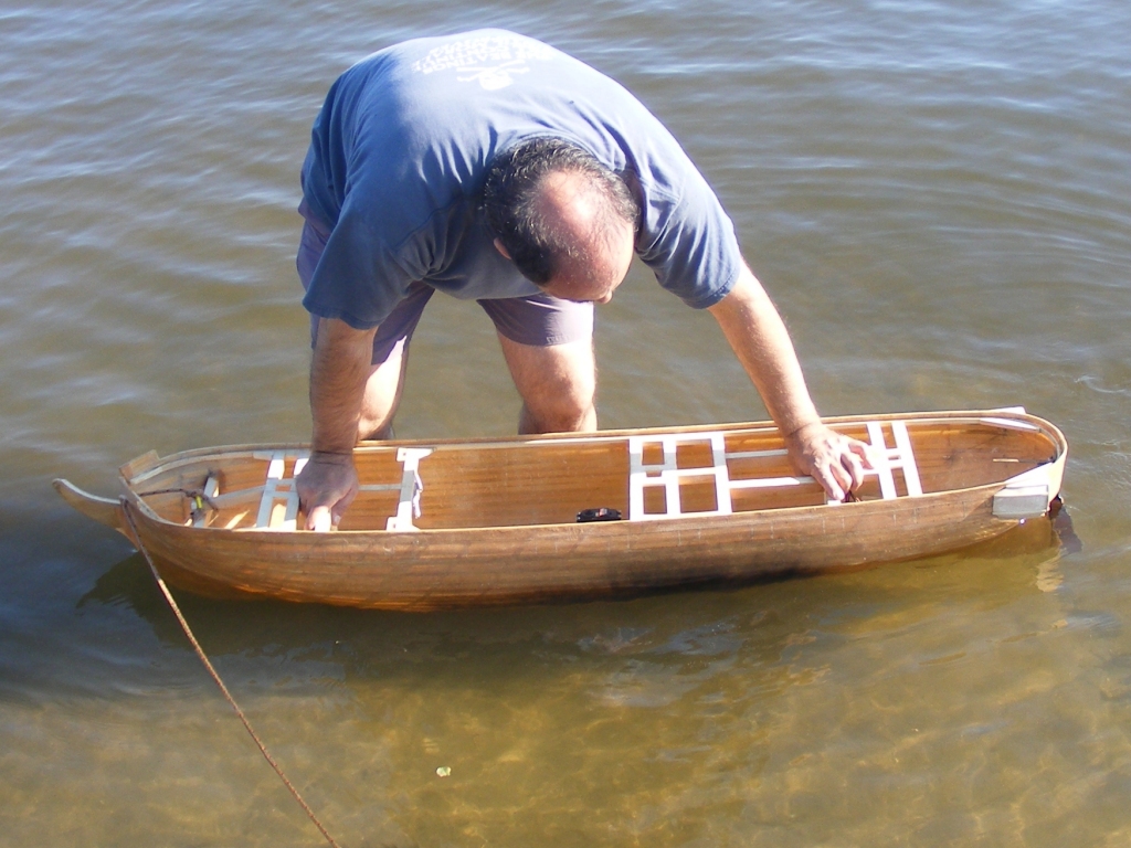
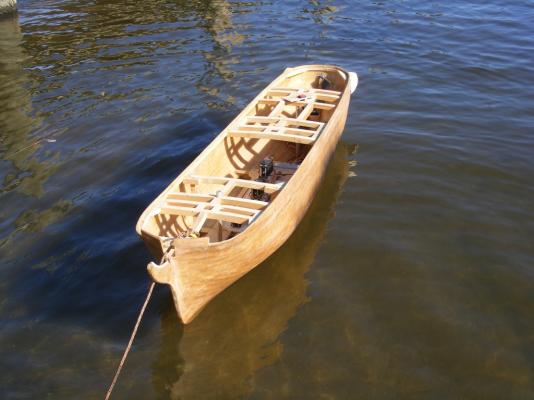
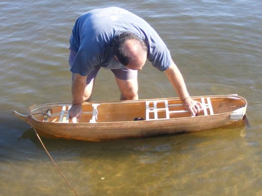
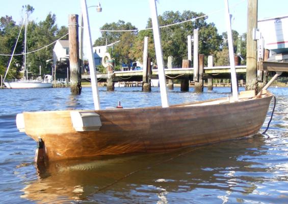
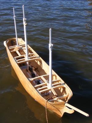
Funny you should mention that lambsbk, as it was about this time the model got wet for the first time On October 4th 2009, I had taken my daysailer Lydia out and tossed Constellation in the truck. When we got back I put the hull in the water for it's first float. I forgot the rods that held the ballast on, so the closest thing that might be deemed a test was when I pushed the hull down to it's waterline. No leaks. On the 7th, wanting a better "test" I tossed her in the truck and took her to the end of my street to Sloop Cove - where else do you float a sloop of war, eh? In total there was 50 pounds of lead on board; 42 in the torpedo, the rest in baggies placed in the hull. There was also about 4 pounds more consisting of battery, radio gear, and a couple of hand tools; plus her lower masts, which together don't weight half a pound. She floated 2 inches above her load waterline. I figure it'll take 12-15 pounds of internal ballast to get her down to waterline, that includes her running gear and battery. Next up: Radio Control
- 553 replies
-
- 11
-
-
- sloop of war
- constellation
- (and 3 more)
-
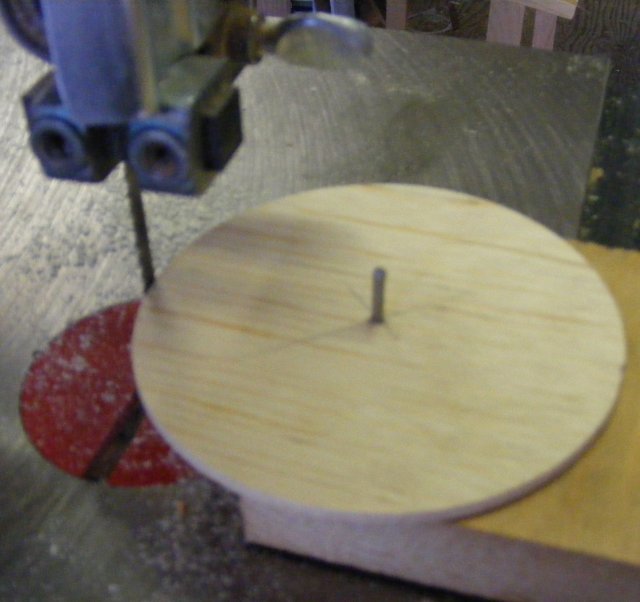
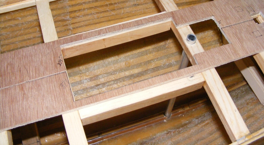
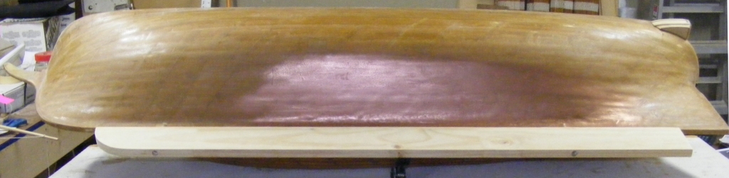
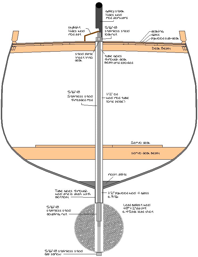
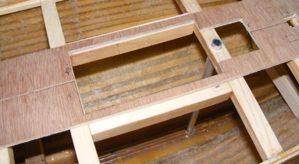
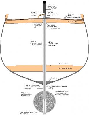
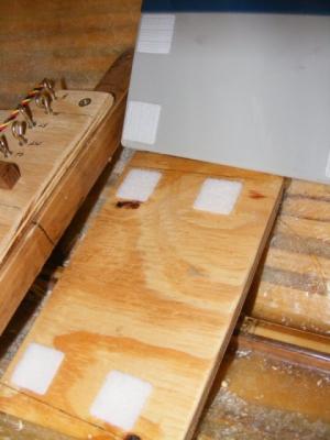
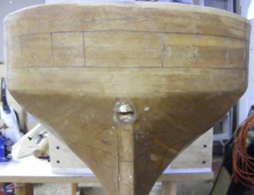
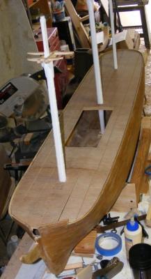
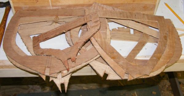
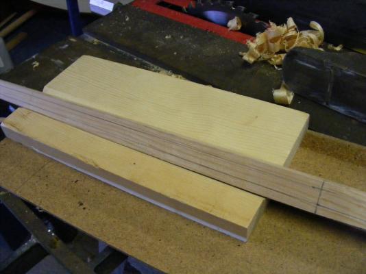
The next step was the removable ballast keel... The ballast would attach to the hull by means of two stainless steel threaded rods that would run through a pair of tubes from the spar deck, through the keel. The forward rod would be disguised with the galley stack, the after one hidden by the skylight that was part of the model's battery hatch made up of the skylight, companionway hatches, and the capstan. Initially I wanted to cast a flat lead bar about 3/4" thick that would bolt onto the keel and weight about 50 pounds, I made a wood mockup but I've never casted that much lead before, so I opted to fill a 2" PVC pipe with lead shot that weights in at about 42 pounds. The model will still require some internal ballast, which will be in the form of lead filled "bean-bags" that will attach with Velcro tabs, like the battery. Then it can be moved to trim the model as needed.

- 553 replies
-
- 7
-
-
- sloop of war
- constellation
- (and 3 more)
-
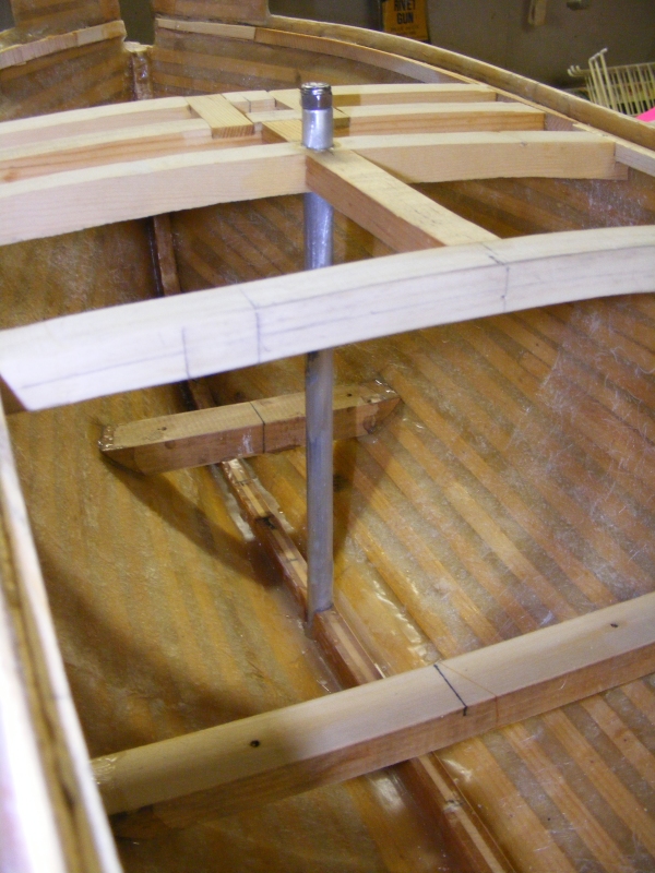
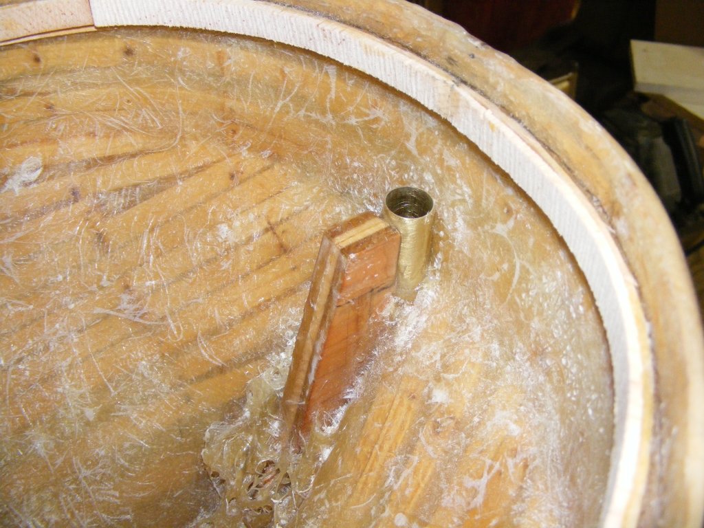
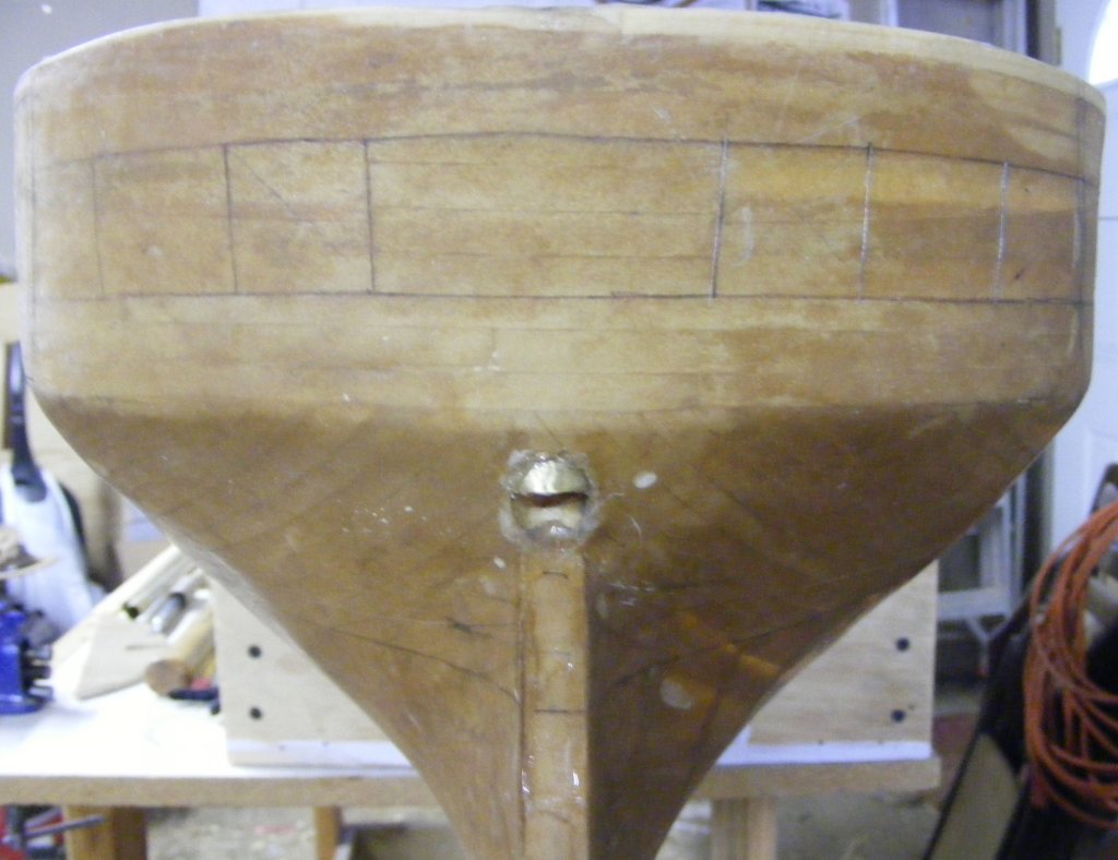
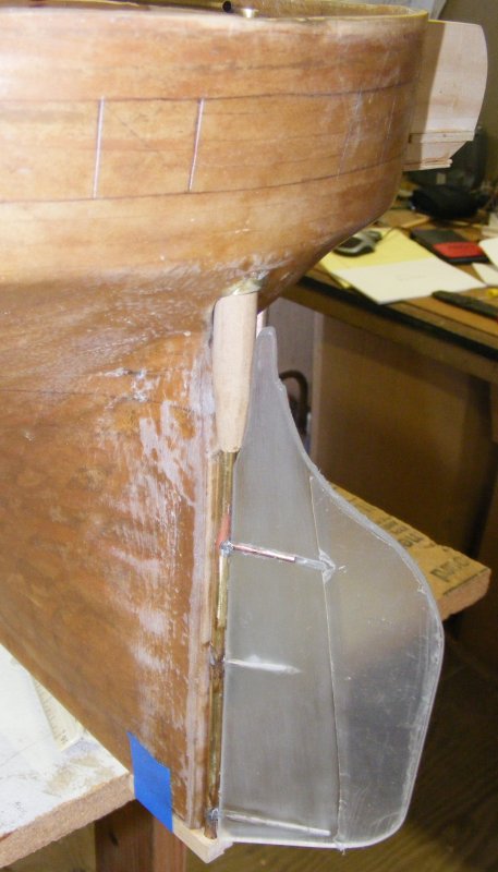
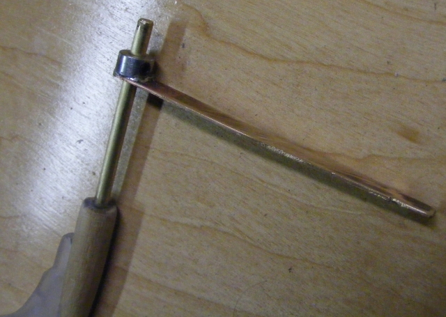
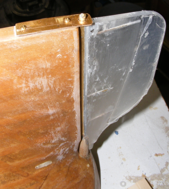
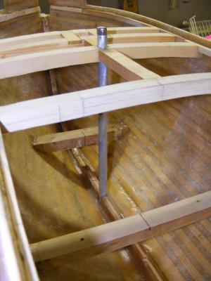
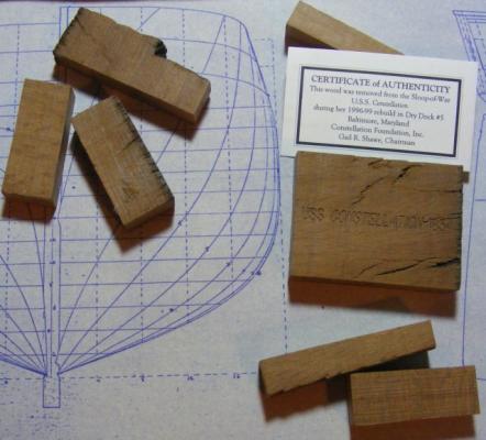
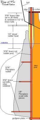
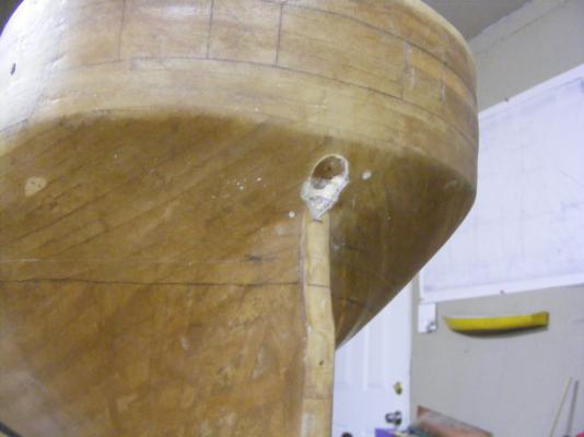
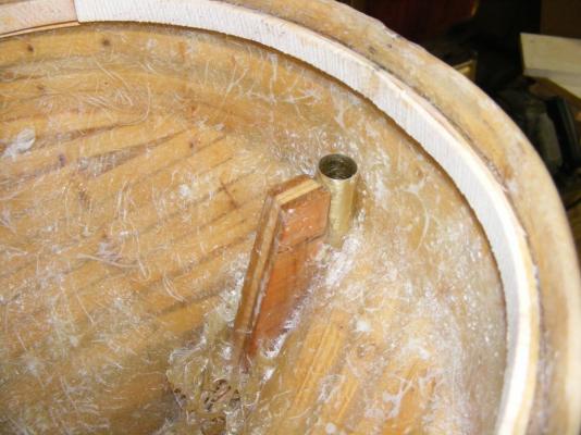
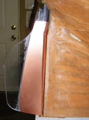
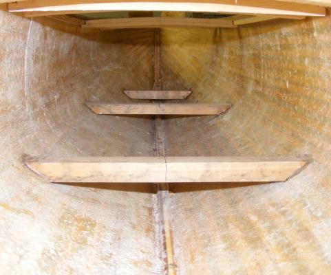
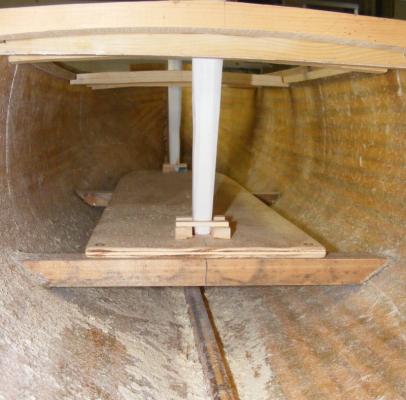
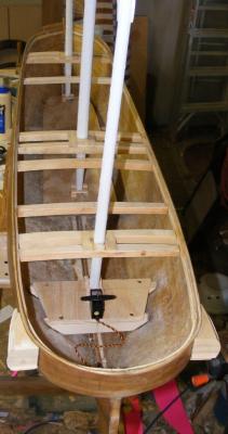
All the deck beams didn't go in at once. Some would have been in the way to do other work in the hull, but the basic framework that provided the main hatch, battery hatch, and mast partners was in place. Below beams were set that carried the mechanical decks where the servos, battery, and other operating mechanics of the model would be mounted. The battery was initially going to be stood up on the keel in a thin plywood box, but at the suggestion of a friend that was sailing a 1:24 HMS Surprise around, I laid it on it's own little deck with Velcro tabs to hold it in place; getting the weight lower in the hull as a result. On a visit to the ship I acquired from it's director a box of pieces of live oak removed from the ship during it's restoration. One was stamped USS Constellation 1854 and will have the model's completion date and my name added to it, then it'll be mounted inside the hull so in the future folks will know what lunatic built this thing. Other bit of live oak were fashioned into the three mast-steps and fastened to the mechanical decks with brass screws. It's really nice to incorporate wood from the original ship into the model. I then focused on the rudder. First I drilled the 1/2" hole in the counter for the bass rudder tube. This would stick out through the counter and approximate the sort of cowl the ship's apparently always had. This tube would be filled with JB Weld epoxy with a 3/16" i.d. brass tube suspended in it. The epoxy would form a top to keep the rudder from riding up. The rudder itself was cut from 1/4" Plexiglas with a larger surface than the scale rudder. Two cheek pieces of 1/8" plexi, cut to the size of the scale rudder, were attached to each side - these would be painted, etc, while the over sized portion would remain clear. The rudder's post was an 3/16" brass rod glued to the back edge of the rudder, with 3/23" brass rods drilled through the post and into the rudder as drifts. The head of the rudder was made from a maple dowell that only reaches into the rudder tube about 1/8" and is the bearing against the JB Weld and inner rudder tube that keep the rudder from riding up. The post rod extended into the hull and has a tiller attached via a steel collar. It extends below the rudder about 3/8" where a gudgeon plate is attached to the hull to hold the bottom of the rudder to the ship. Removing the tiller and gudgeon plate allow the rudder to be removed if the need arises.


- 553 replies
-
- 5
-
-
- sloop of war
- constellation
- (and 3 more)
-
I agree, I've seen wonderful jobs done on this plastic decks, but what you get with wood is hard to beat. Bass strips can be stained and do a very nice job. You could lay a sheet subdeck and cover it with strips making it, in essence, bass plywood. The hatch combings are, I believe too short anyway. The gun deck (& berth deck) combings were typically taller than the spar deck's as well.
-
I never got why Revel never included such details as bitts, stove, etc. As you've shown, these details add a great deal to the model. I always thought a mini-diorama of the crew clearing for action and breaking down the cabin bulkheads would be a nice touch, but two of the three I've built were RC and had no gundeck to speak of.
- 601 replies
-
- 1
-
-
- constitution
- revell
- (and 1 more)
-
Instead of a full turn around the bar of the bit, bring it up around the front of the post and then aft in an S pattern - it's more seaman like.
-
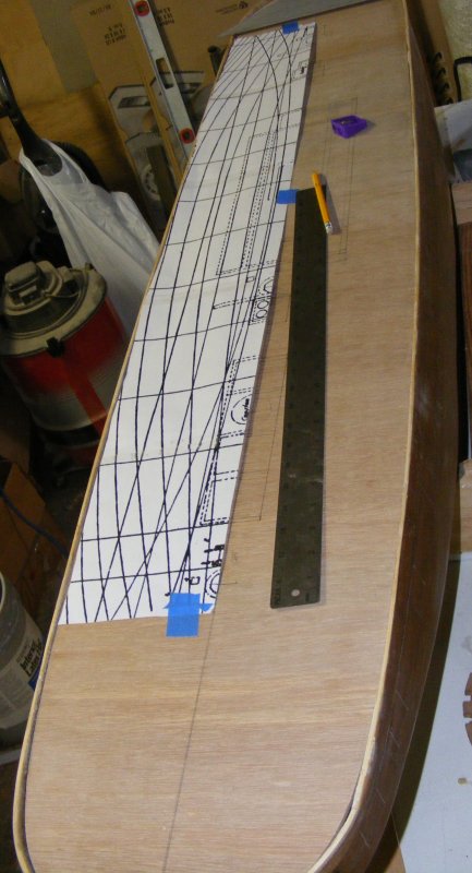
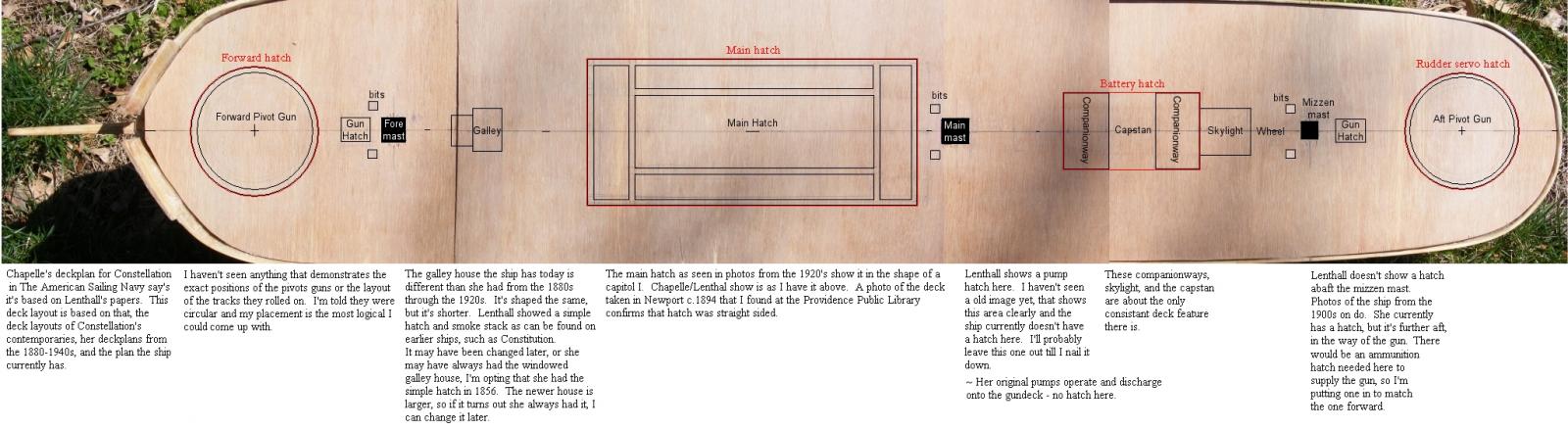
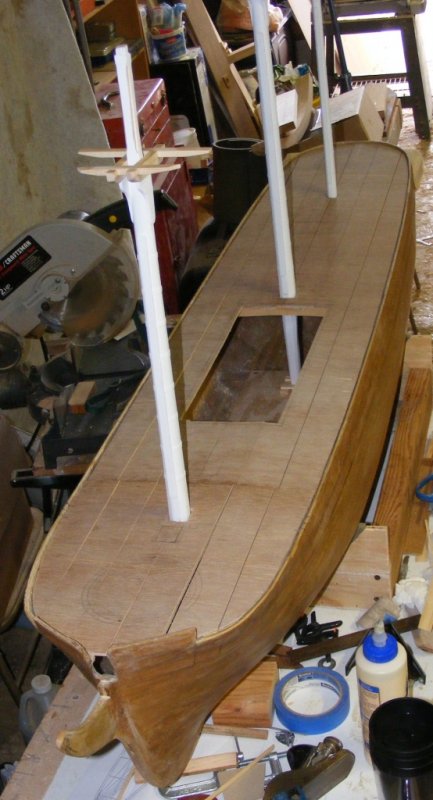
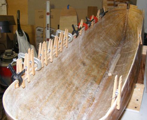
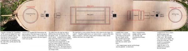
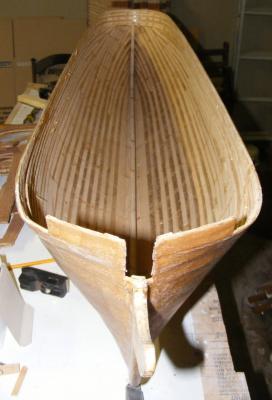
The deck clamp was built up from two layers of pine strips, much the same as the hull's battens. The sub deck would be 3/16" luan plywood with strips glued down on top for the visible decking, so the deck clamp was set down so the finished deck would be flush with the sheer. The subdeck was cut from the ply and fitted Then the positions of the hatches and deck furniture marked on it to determine where the deck beams would be needed. At this point I only had two sources for the ship's spar deck layout; Chapelle's drawing of Constellation from The History of the American Sailing Navy, and model plans of the ship from A.J.Fisher which the people restoring the actual ship told me they were using. The Fisher drawings are of the ship in 1941 and very crude. Chapelle's drawing says they are from the original drawings, but the 1854 drawing of the spar deck was missing from the National Archives. The major differences being the main hatch in 1941 was shaped like a capital I and the galley hatch had a house on it - neither of which are on Chapelle's drawing. I opted to go with Chapelle. Later, I found more information that vindicated my decision. Down in the hull, straight beams were installed to carry the equipment decks where the radio equipment and sail controls would be mounted. I also decided to step the masts on these decks. The deck beams were laid out to form mast partners and hatch framing. Each beam was cambered and notched to hook under the deck clamp. The subdeck would be epoxied on and sandwhich the beams and the deck clamp all together. Temporary mast steps were put in to get the mast partners properly aligned, and the subdeck was sawn into 2 inch wide strips so it could conform to both the beams camber and the boat's sheer.


- 553 replies
-
- 6
-
-
- sloop of war
- constellation
- (and 3 more)
-
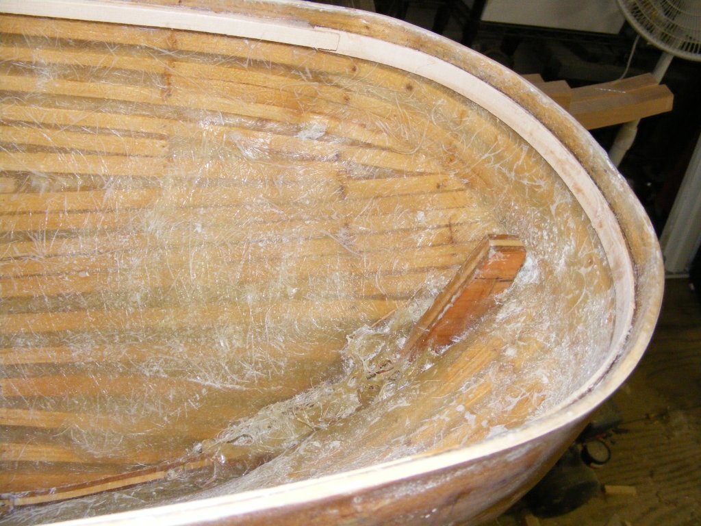
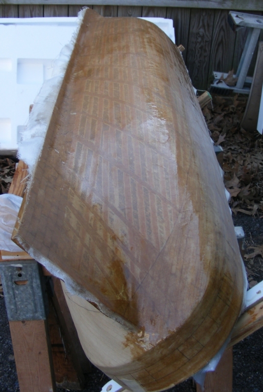
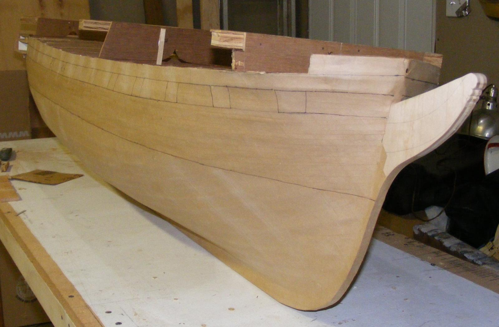
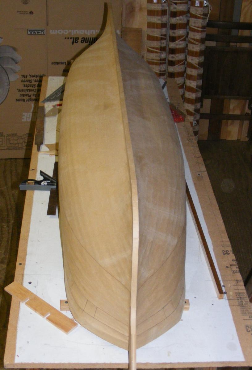
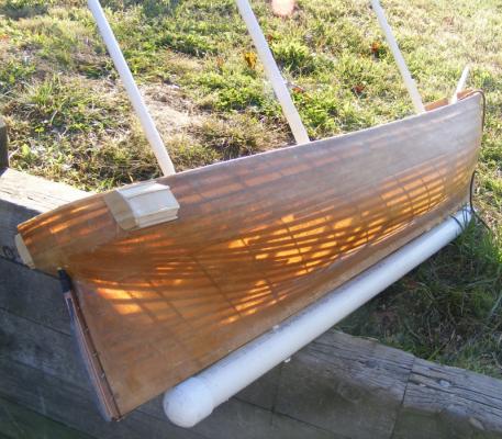
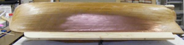
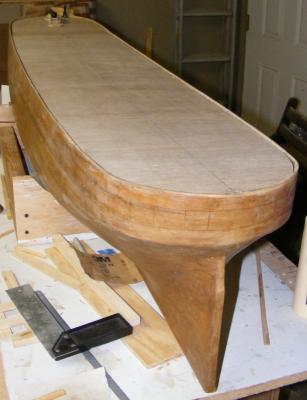
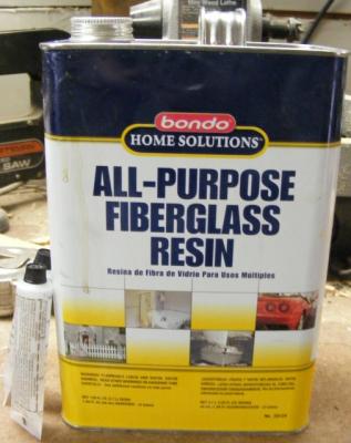
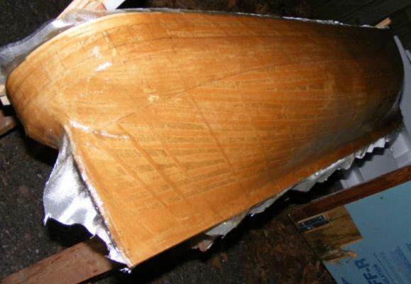
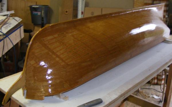
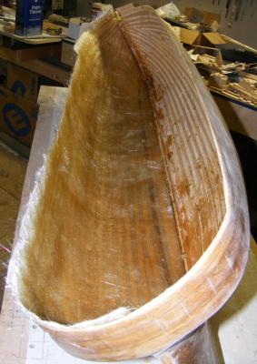
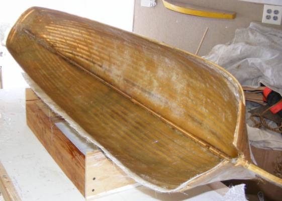
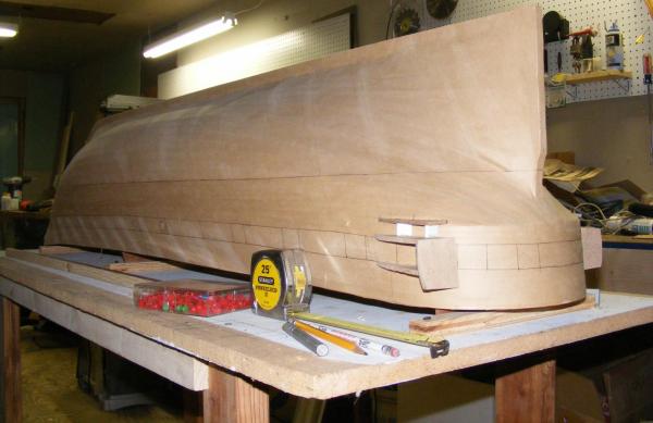
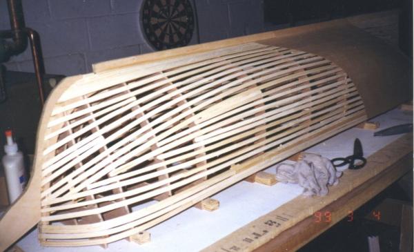
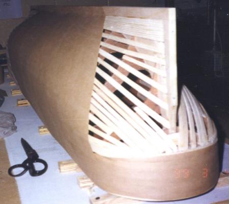
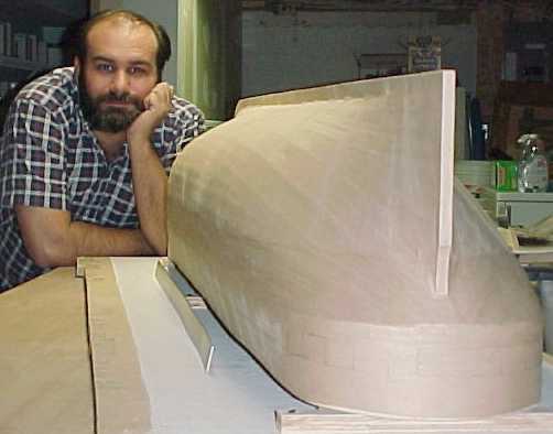
Prepping to Glass - or how not to build a hull. April 2009 The plug, now "the hull." needed to be prepped in order to be glassed. The card-stock quarter galleries were tossed; the stem knee shaped and tapered; and some of the brown paper detailing removed. The sheer was trued-up and every thing was lightly sanded. I used the polyester resin available at the local hardware superstore, and laid up one half at a time with 4oz cloth. After one side set-up, it was trimmed and the other side laid up. The next day that was trimmed, the whole hull sanded, and another coat of resin rolled on: Once that was set and sanded all the forms were carefully removed. The hull was flimsy with only the battens, paper tape, and some very fine glass cloth: Glass matting was laid in, one side at a time. Extra resin was poured in while the hull laid on it's side, to try and fill the spaces between the battens. This probably would have been better done with Water Putty, or some other filler that would have filled the space more solidly: I now had a solid fiberglass hull as the matting made it very rigid. This is NOT a good way to make a hull for an RC boat. The original plan, before I was distracted by Mowill's book, was the way I should have gone from the start; wood planking on forms, covered with glass and resined inside. If you're following this with the idea of doing one yourself, learn from my mistakes - look at how I built the hull for my Macedonian. Next: Deck Framing


- 553 replies
-
- 9
-
-
- sloop of war
- constellation
- (and 3 more)
-
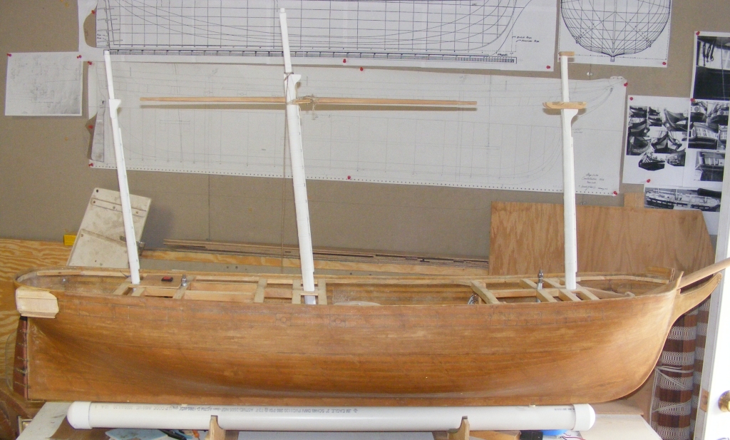
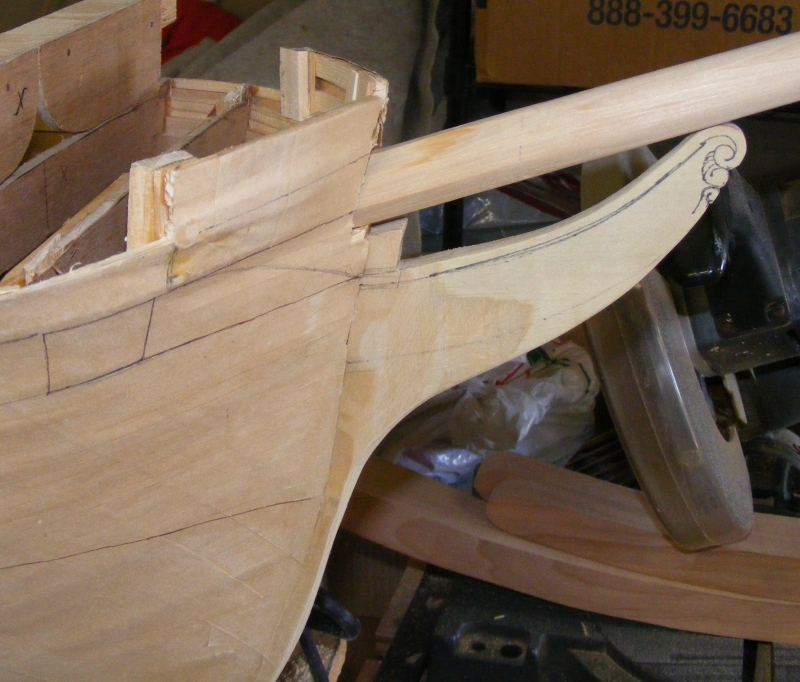
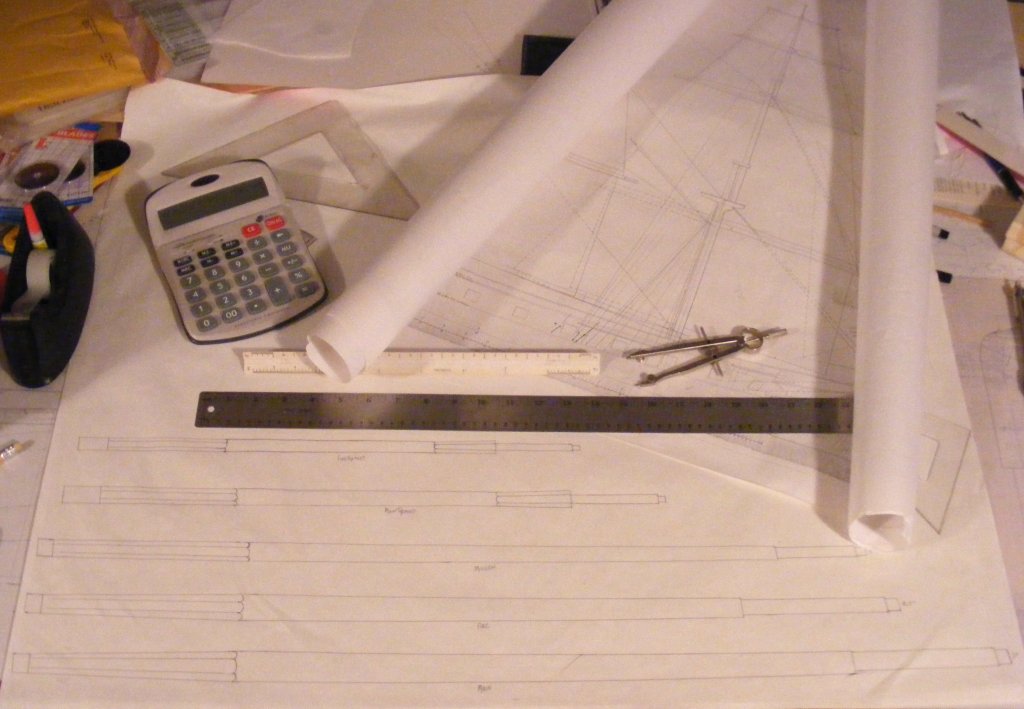
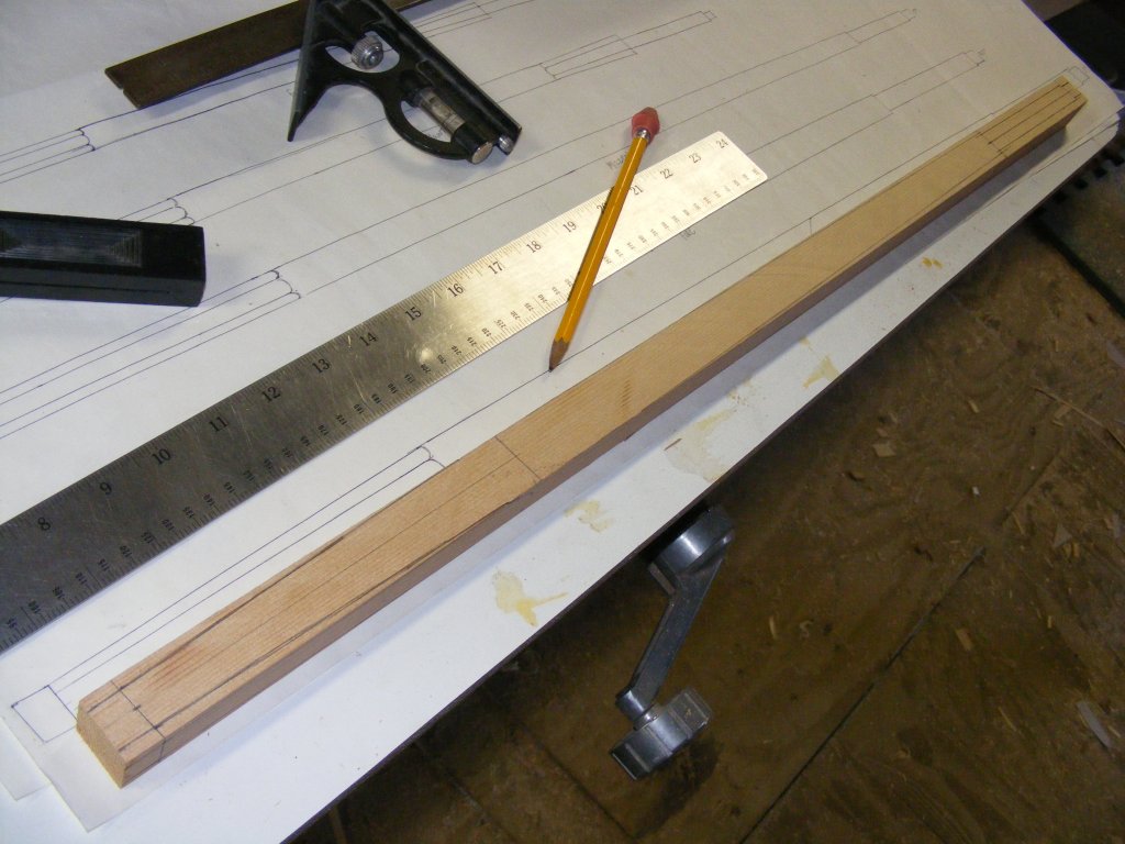
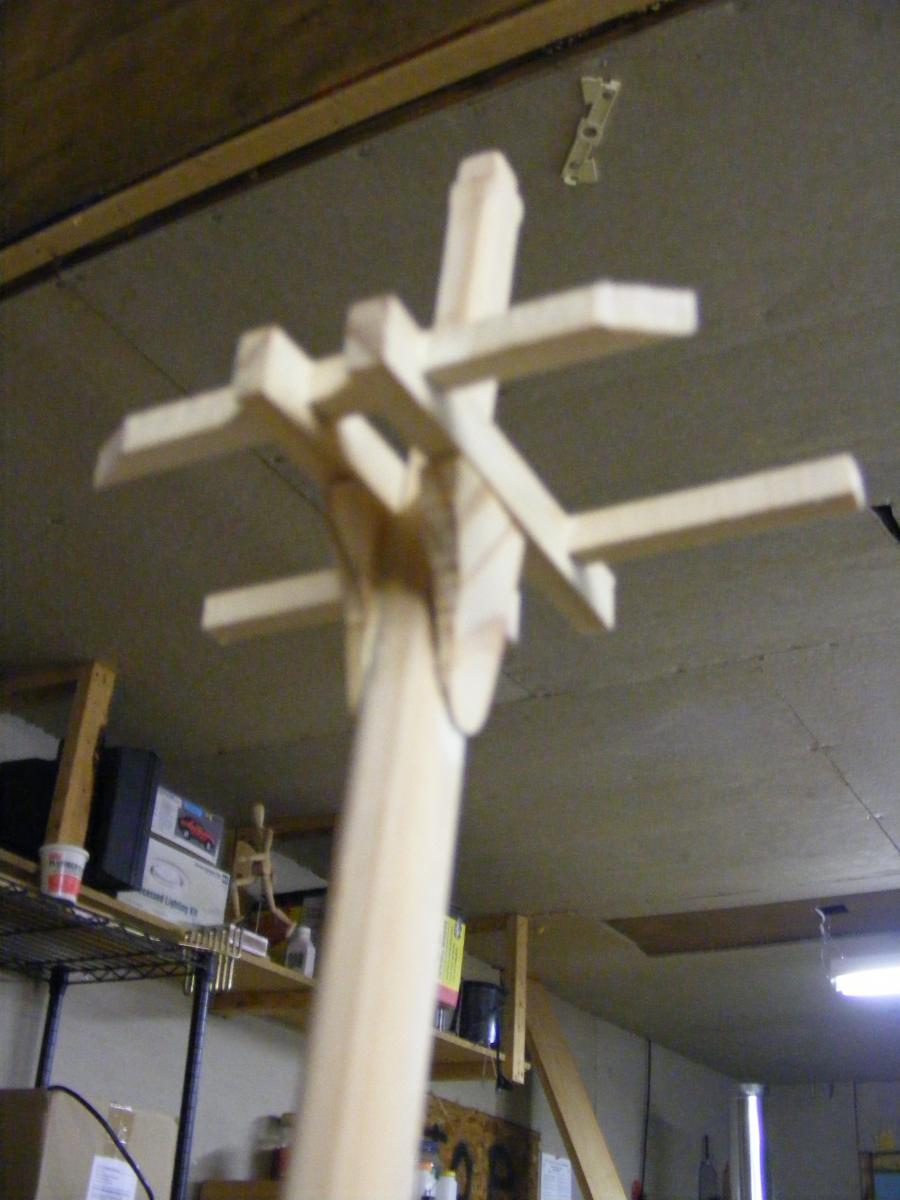
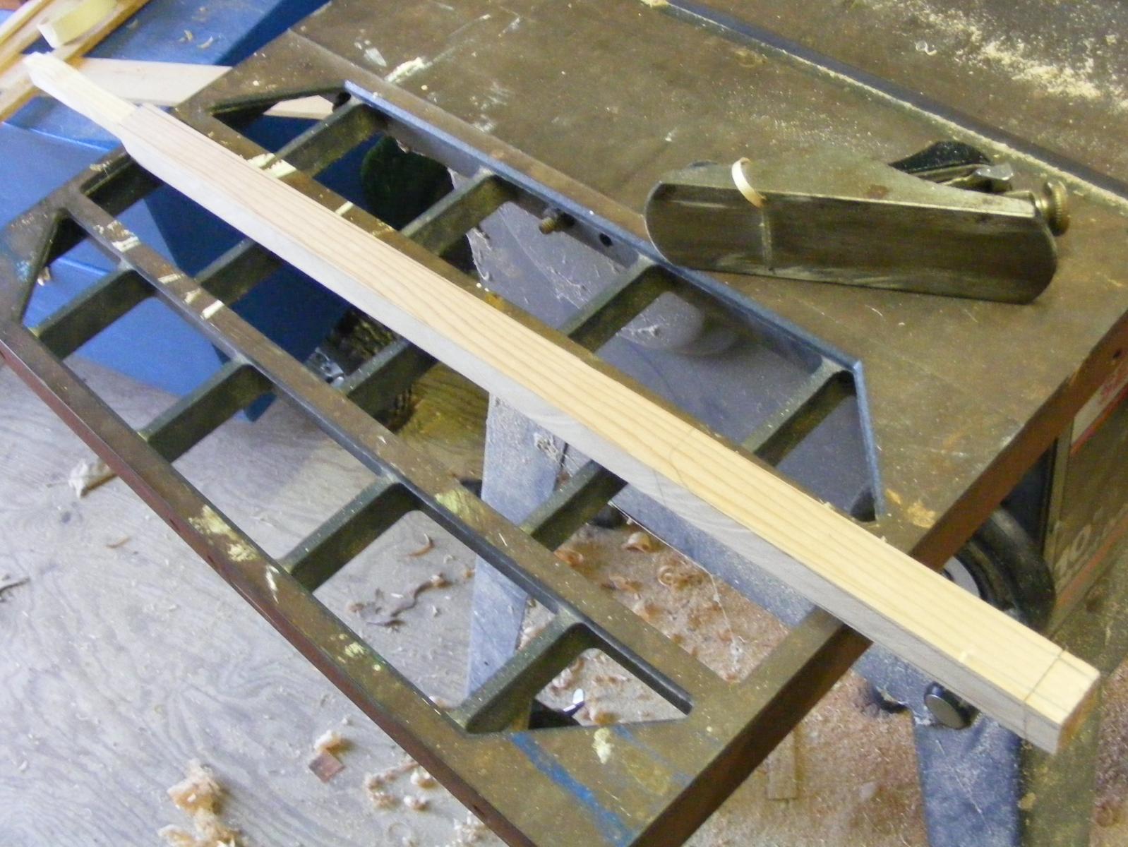
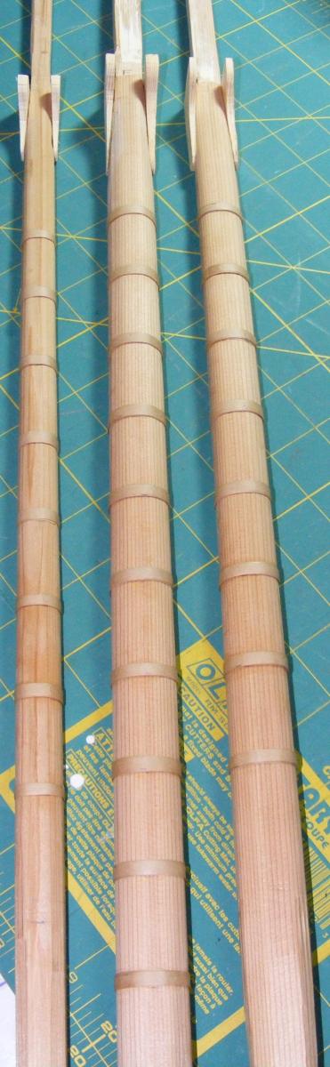
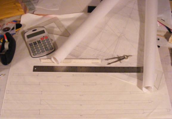
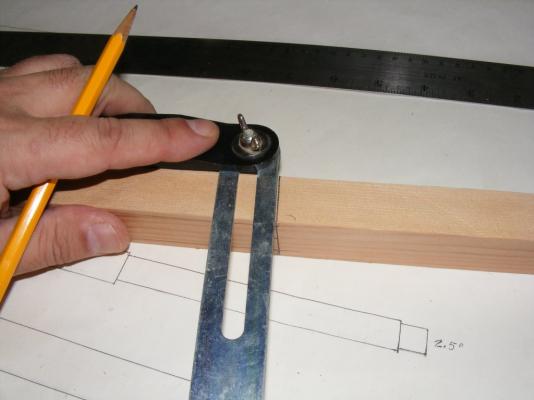
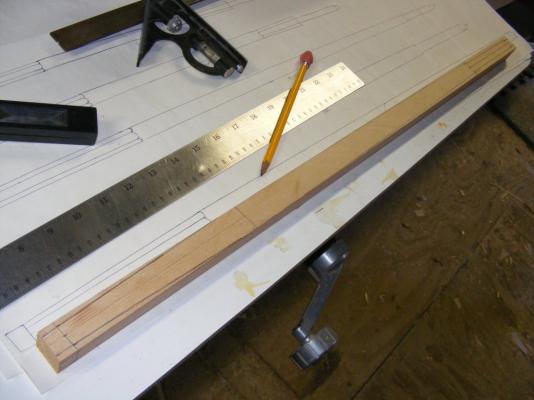
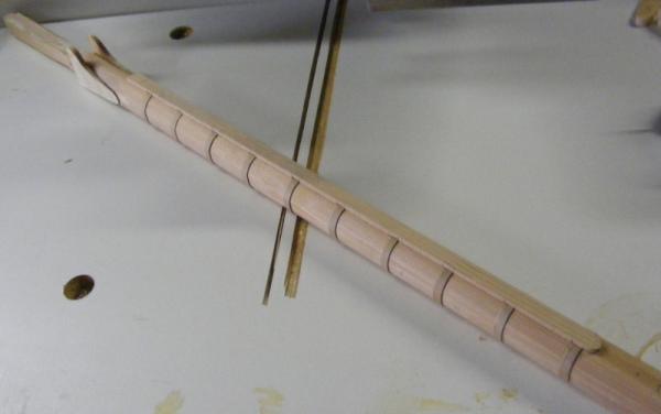
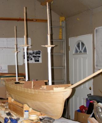
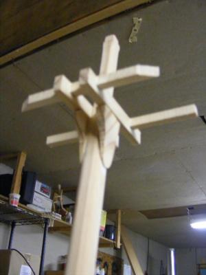
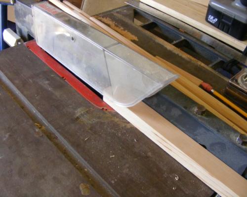
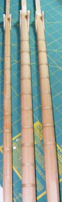
While I considered what to do about the plug, I found some very nice white cedar while getting something else at the lumber yard, so I began making the lower masts. Since I had no plans for Constellation's spars specifically, I used several sources for the details, including Spars and Rigging From Nautical Routine, 1849 and Biddlecomb's Art of Rigging, but the best source I found for this 1850's warship was Luce's Textbook of Seamanship which has some very detailed drawings of the rigging of this period. After drawing the spars full-scale, I cut the cedar to the rough dimensions on a table saw: I then marked out the details and the taper: Shaved the taper, then marked the spar to make it 8-sided: The masts were banded with the same brown paper tape the plug was made from, the hounds and the front fish were made and attached: The cross-trees and trestle-trees for the lower tops were made along with a rough set of mast caps: The topmasts were made from the same cedar and in the same manner as the lower masts. Some temporary mast steps were placed inside the plug, a stand made from 3/8" plywood to hold the model up, and some paint went on the lower masts. By this time I was convinced that glassing the plug and making it the model's hull was the best course to take... Next: Prepping to glass

- 553 replies
-
- 12
-
-
- sloop of war
- constellation
- (and 3 more)
-
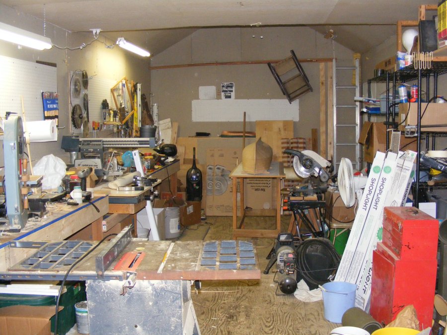
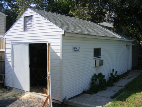
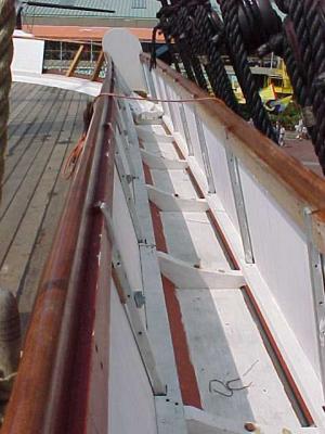
Work Resumes So, life went and changed things around a bit. My wife and I went different ways and the farm was sold. I moved into an apartment and the workshop and the plug went into storage. In the late spring of 2008 I bought a house with a 12 x 29 shed that became my workshop, subsequently known as "The Damn Yankee Workshop." With the shop set up, I began to work on the plug in earnest. Those details needed for the mold still had to be added and the quarter galleries were a big part of that, so that's where I started. These things didn't need to be very structural as the entire plug would be destroyed in removing it from the mold. In the mean time I visited the restored vessel and learned some things. The bulwark on the spar deck was actually planked up hammock stanchions. When the ship was being "restored" as a frigate, they took off the hammock irons and tossed them into the bilges, the restoration recovered all but one and reinstalled them. This changed the shape of the hull for me. Instead of "solid" bulwarks continuing smoothly up to the cap rail, the hull stopped with a cap on top of the waterways, and had these stanchions mounted on top of that cap and covered with wainscoting. So, I cut the plug down to the lower level at the top of the waterways. The whole idea of the plug being destroyed when the mold was made began to nag at me. There was a chance, a very good chance in my opinion, that the mold might not turn out and the whole thing would be a disaster and a major waste of time and effort. Next: A Course Change


- 553 replies
-
- 5
-
-
- sloop of war
- constellation
- (and 3 more)
-
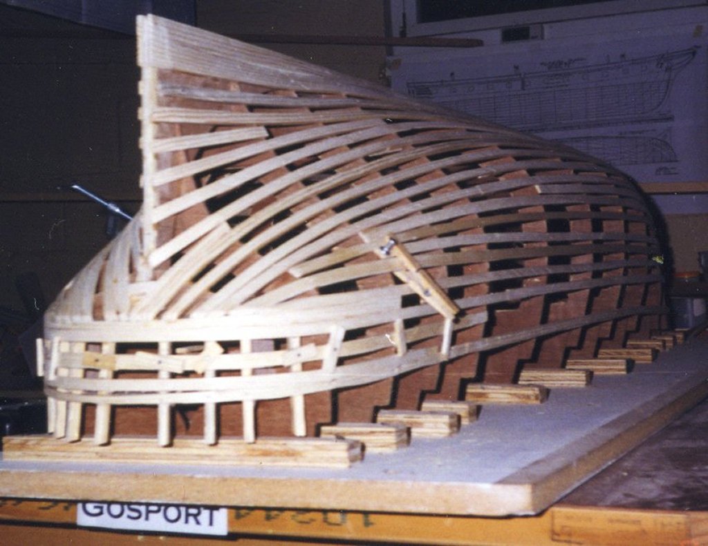
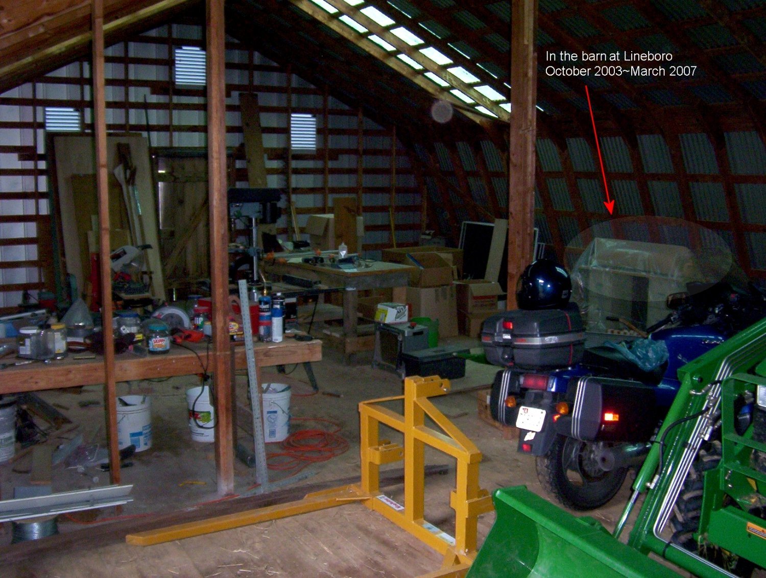
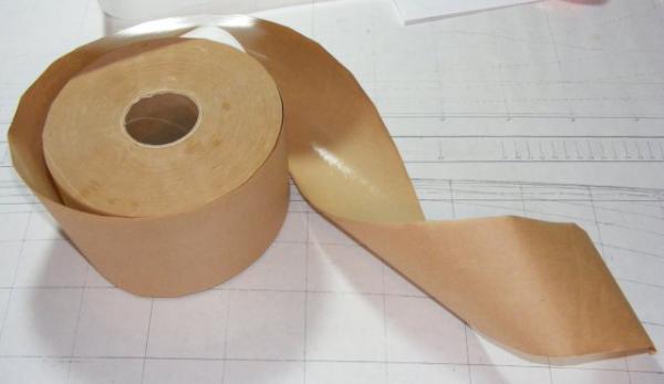
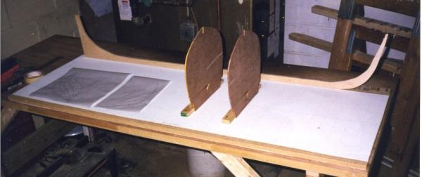
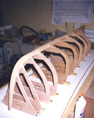
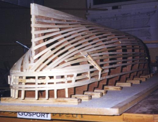
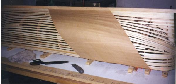
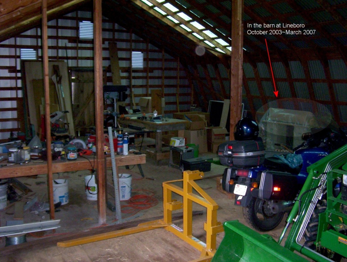
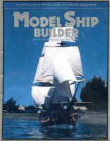
Much more regarding the details of why I chose this ship to build; history of the ship; and other items of interest can be found on my web page for this project. This "log" is to replace the one that had been posted here before the forum crashed and lost a lot of data. Beginning Having the plans already in the size I wanted saved a lot of time getting started, and I used the Model Ship Builder article as a guide at first. A bit of scrap particle board from a remodeling project was used as a building board. The forms were cut from scrap wood paneling, and the keel was some 1/2" scrap birch plywood from a cabinet I built. This was all stood up by the end of March, 1999. Then I discovered a book; William Mowll's Building a Working Model Warship:HMS Warrior, 1860. Mowll covered his forms with battens instead of planking and covered that with gummed brown paper packing tape over which he applied masking tape to create a plug for making a fiberglass mold. The masking tape was to give the texture of Warrior’s cast iron plating. I happened to have a large roll of the brown tape, and got the idea of using this method to make a plug and cast 3 hulls in glass fiber. I didn't need the masking tape as Constellation wasn't iron plated, I would use the brown tape to impart planking details to the mold. So, moving forward with this plan, I battened the forms with scrap white pine strips... ...and proceeded to cover that with the brown paper tape creating what would be a plug for a fiber-glass mold. The tape shrinks a bit when it dries and can be sanded. Once the form was covered diagonally I began applying a second layer in the form of strips to represent planking, gunport lids, and even copper bottom plating - all this detail would be picked up by the mold and imparted to the glass hull when it was laid up. The plug still needed more details, like quarter galleries, but none of the drawings available gave these details, so I had to go digging. In the meantime we sold the house and bought a small farm where we kept some horses and I commuted 65 miles one-way to work. The plug went into the barn, covered in plastic, and wasn't touched from 2003 till 2008. Next: Work resumes.

- 553 replies
-
- 13
-
-
- sloop of war
- constellation
- (and 3 more)
-
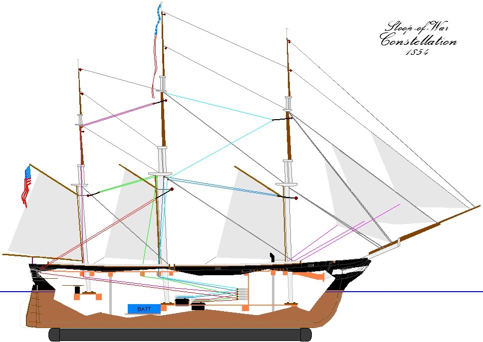
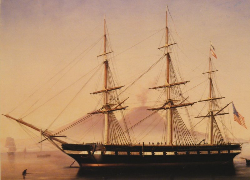
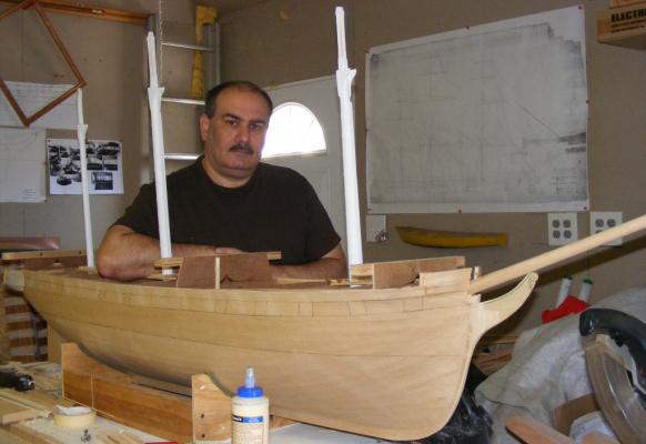
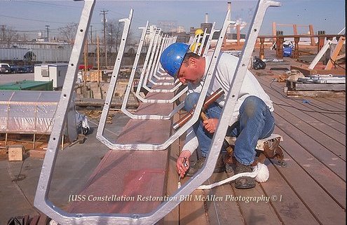
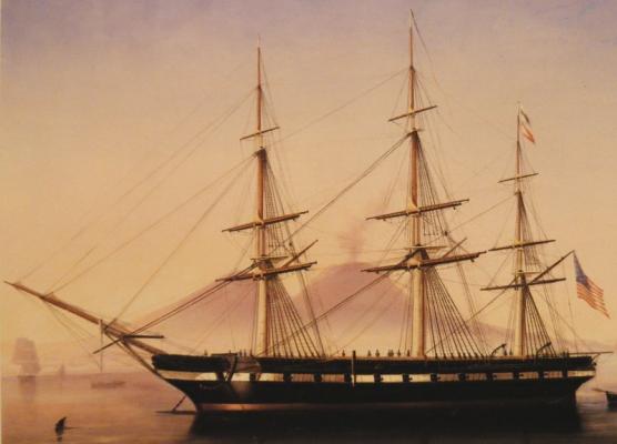
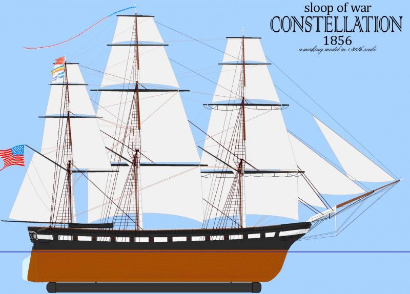
Inspired by a large RC model of the Rattlesnake featured in an issue of Model Ship Builder magazine, I looked around for a subject to built and decided to built the ship in my own back yard, the sloop of war Constellation tied up in Baltimore's Inner Harbor since the mid 1950's. Some video of Rattlesnake Constellation was a sloop-of-war, of 22 guns, designed by John Lenthal, and built in 1854 by Gosport Navy Yard at Norfolk, Virginia; the last US warship designed and built to operate under sail alone. For a long time she was believed by many to be the old frigate of 1797, rebuilt and moderized, and that debate has raged in the maritime history community for decades. Her lines and sail plan were acquired from the National Archives where I got to handle the actual hand drawn documents. I decided to build her as she appeared in a portrait by deSimone when she was in Naples in 1856 and still a new ship. Her lines were drawn in 1:36 scale, which was perfect, giving a model: Beam: 13-5/8" (34.713 cm) Length over the rig: 96" (243.84 cm) Width over the rig: 36" (91.44 cm) ~ Main yard w/o stuns'l booms. Length on deck: 61" (154.94 cm) Length between perpendiculars: 59-1/8" (150.178 cm) Draft, without ballast keel: 7" (17.78 cm) With 3-1/2" ballast keel: 10-1/2" (27.94 cm) Height bottom of keel to main truck, without ballast keel: 65" (165.1 cm) With ballast keel: 69" (175.26 cm) Sail Area: 2,807.01 square inches in 17 sails (19.5 sf, 18,109.7 scm, 1.8 sqm) This log will cover my work on this model since it began in 1999 up to where it is now. Author's Note: This is a log of how I am building this model, not a guide to how a model such as this ought to be built. It's full of fits and starts, changes of mind, errors, re-do's, more error's, a few mistakes; and somehow, despite all this, it seems to be becoming a working, sailing model that actually looks something like it's namesake. The director of the actual ship recognized it on first sight - I take that as a good sign! If you're considering taking on a project like this, please, please, don't let this build log deter you - it's not nearly as difficult as I make it seem. Just take away from it that which helps you along, and ignore the rest.
- 553 replies
-
- 4
-
-
- sloop of war
- constellation
- (and 3 more)
-
R/C ...WHAT TYPE OF GLUE SHOULD BE USED???
JerryTodd replied to Cap'n Rat Fink's topic in RC Kits & Scratch building
I use Tightbond III for wood-to-wood joints, and epoxy everywhere else. -
BTWY: You should resin the inside thoroughly before attaching anything inside the hull. Deck clamp, mast steps, framing, etc can all be epoxied in after, but if resined after attachment, there's a place for water to get in. If water gets in, even a small amount, it will swell the wood causing joints to open, the glass to separate, and make more places for water to get in. Holes in the hull, for prop shafts and the like, ought to be over sized, filled with epoxy and redrilled to the correct smaller size to prevent any wood from being exposed. You might consider painting bare wood with Ethylene Glycol (automotive antifreeze - not Propylene Glycol). Glycol soaks into the wood and crystallizes which doesn't allow in water or mold which causes rot. All my models get this treatment. Allow it dry thoroughly and then resin it. If you look close you'll see the wood has little sparkles in it because of the crystals. A lot of wood objects recovered from shipwrecks are preserved this way it keeps out water without shrinkage. Be very sure to follow the safety precautions on the container, I had a neighbor whose dog lapped up a puddle of it from a leaking bottle and it later died as a result - they thought it was rabid until it was tested.
-
These boats didn't rely on firepower, but on speed and the ability to sail close to the wind. Most were armed with 6 pounders, or a single 18 on a pivot amidships, and maybe a swivel or so on the rail. They carried large crews not to board and fight, but to send onto captured merchant vessels to take back in, each prize crew depleting the schooner's crew - the more men they carried, the longer they could stay out and capture prizes.
-
That's a lot of thick ribs in a hull that even at that size, doesn't offer a lot of space. With the outside glassed and the inside given a coat or two of resin, you really only need a couple of those. I kept one to brace the dagger-board trunk, and one for the motor mount. The thing that really made the hull solid was the deck clamp and beams. What ever you decide to do, remember to make it possible for water to get through fore and aft. Water WILL get in, if only a little, and you want drain holes in any bulkhead so it all goes to the lowest point where it can be pumped and dried out - otherwise you get mold in there and that gets really disgusting really fast. It'll be a very hard hull to reach into and clean. Consider too keeping the hull as light as you can. That gets more weight onto the removable ballast which is deeper and stiffens the boat more, and allows you to trim her easier with internal ballast. It also makes handling the model a easier if the 20-30 pounds of sailing weight can be shed when she's not sailing.
-
I'm sorry, but every time I look at the lines of a French frigate the rap song "I like Big Butts" pops into my head. I can't figure out why. Happy Birthday
-
Mock up and operate the main brace to see if it fouls anything without the bumpkin - though I would wager she had them, I haven't seen an original plan of an American war ship that didn't have them right into the 1870's. There's other things "missing" from the Hull model, most notably the ship's wheel - I wouldn't take so minor a detail as written in stone.
-
Um, there's 3 heads'ls; forestays'l, jib, and flying jib. You'll need to make the main tops'l, fore t'gallant, and flying jib removable except when the air's are light. You might be able to shorten the foot on the forestays'l and jib to minimize the overlap. A sliding sheet would work well in that case; that is the sheet runs through the clew grommet and back to the servo in a loop. A pair of knots or beads on the sheet on either side of the sail grab the clew and sheet the sail home when the servo's nearly at full travel. Using this, you shouldn't need booms on any heads'l. There were several historic privateers the size of Pride (90' on deck) armed in various ways; a swivel gun amidships could be a 12, 18, or 24 pounder, or even a 32 pounder Carronade. 4 and 6 pounders in the broadside was most common - remember these boats were meant to intimidate merchantmen, not go toe-to-toe with men-o-war - although a few did. You ought to look up Tom Gilmer's "Pride of Baltimore" ISBN: 87742-309-1 and Howard Chappel's "The Baltimore Clipper" ISBN: 0-51202484 (I have a paperback version of this one you're welcome too if you'd like it) These books go into the history of the type, how they were built, armed, and used. One thing to remember if you're looking at my model, either of the actual Prides, or any "recreated Baltimore Clipper" that may be sailing about now-a-days; NONE OF THEM were/are built, rigged, or fitted out like a Baltimore Clipper of the early 1800's - they were/are all modern vessels with modern adaptations; for instance: They all have wire standing rigging which will be much thinner, noticeably so, than natural rope rigging was on the originals. They have cabin trucks all over the deck for crew and passengers when the originals would have had little or nothing in that regard. Many, including the first Pride, had "roll-bars" made of steel tubing on the taffrail for the boom to sit on - none of the original boats would have had such things. The point is, are you modeling a Baltimore Clipper or a modern recreation? I'm doing the latter, I think you're after the former. You should keep this in mind in line with the level of detail you're after and the simplifications needed for a working model. BTW: Can you open an Excel spreadsheet or should I put this spar table in a PDF?
-
Working on tabulating Pride's spar dimentions for you; ie, I went to the other house and got the plans out.
-
By 1800 speaders were in use as sprits'l were going away. The Chesapeake schooners, or Baltimore Clippers, had long nearly horizontal bowsprits that couldn't mount a sprits'l - no room below it. A dolphin striker and spreaders were standard fare. Netting on the other hand, didn't start showing up until the 1840's or so. The original Pride didn't start out with bowsprit nettings, but got them after soon after her first cruise down island for the safety of the crew. That low long bow sprit on that low almost sheerless hull was a dangerous place to be in a seaway.