Marsares
-
Posts
52 -
Joined
-
Last visited
Content Type
Profiles
Forums
Gallery
Events
Everything posted by Marsares
-
 Well, unfortunately the Syren is stil lingering in the drydock as our twins have arrived and the combination of sleep deprivation and nappy duty is keeping me away from the ship. Even dreamed about her last night, about putting her in storage. One could say it was a nightmare!
 -
Progress has been non-existent the last month or so. With the twin babies arriving in the next three weeks or so, my Missus put her foot down and told me that the baby-room was the priority. :-)
-
You are off to a flying start!
-
Have fun, it is a really fun build and I am having a blast although I cant find enough time to work on itl there are plenty of Syren build logs that will complement the excellent manual. Looking forward to your build!
-
Progress has been slow this weekend. Being away from the missus the whole week I dont always feel inclined to disappear too much and work on my ship as I want to spend time with her. Nevertheless, I managed to line up the stern gunports properly so the cannons will fall in the middle of the port, but when I started to chisel away excess wood of the gunport lintels and sills I managed to drive a chisel into my thumb. Nothing major, but felt that perhaps I should take a breather and finish it coming weekend. Started to think about purchasing additional wood for the hull planking as I want to do it in pearwood and ideally buy some sheets so I can try some spiling rather than planking with just straight strips. Found a good supplier in the UK, so doing some calculatiins on how much in need and wilk probably order some, initially for the exterior planking only.
-
Thanks Al, really appreciate the kind words. I think my education as an engineer has taught me a certain structured way of thinking and to measure everything - and again - before you commit. Other than that, all it takes is patience... which I'm learning to have more of! :-)
-
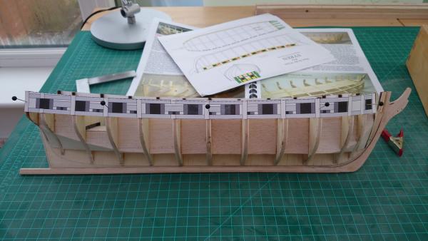
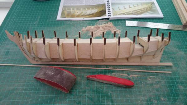
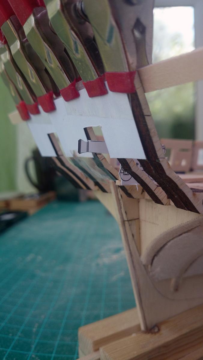
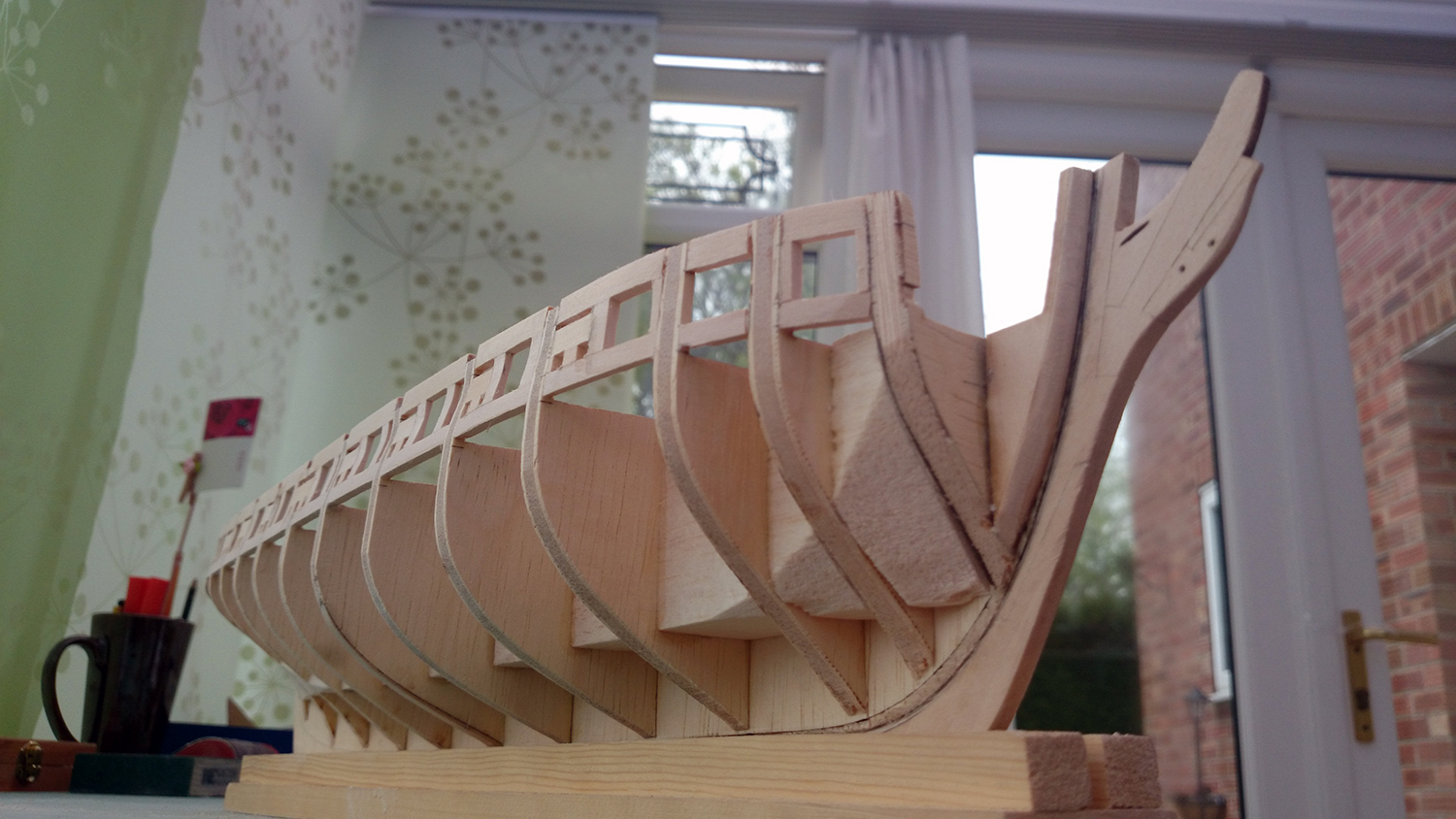
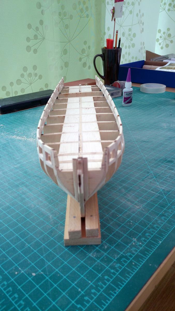
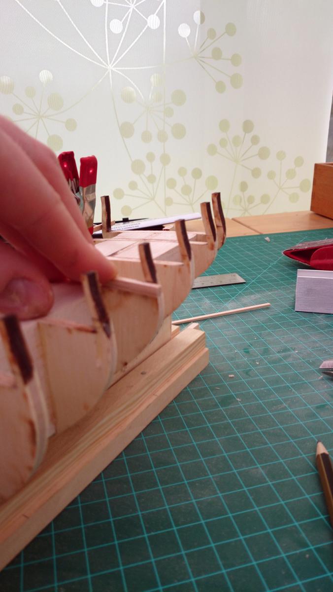
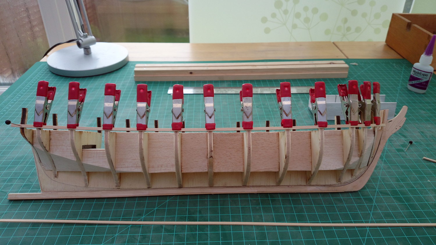
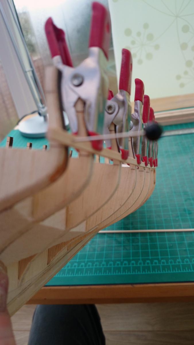
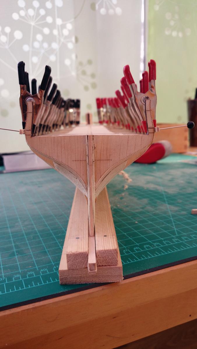
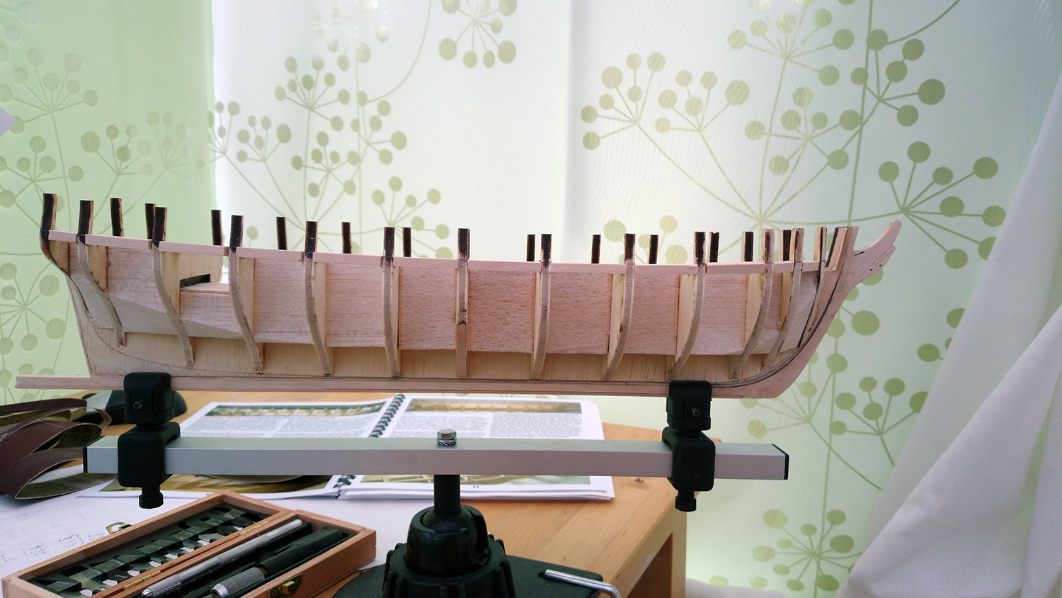
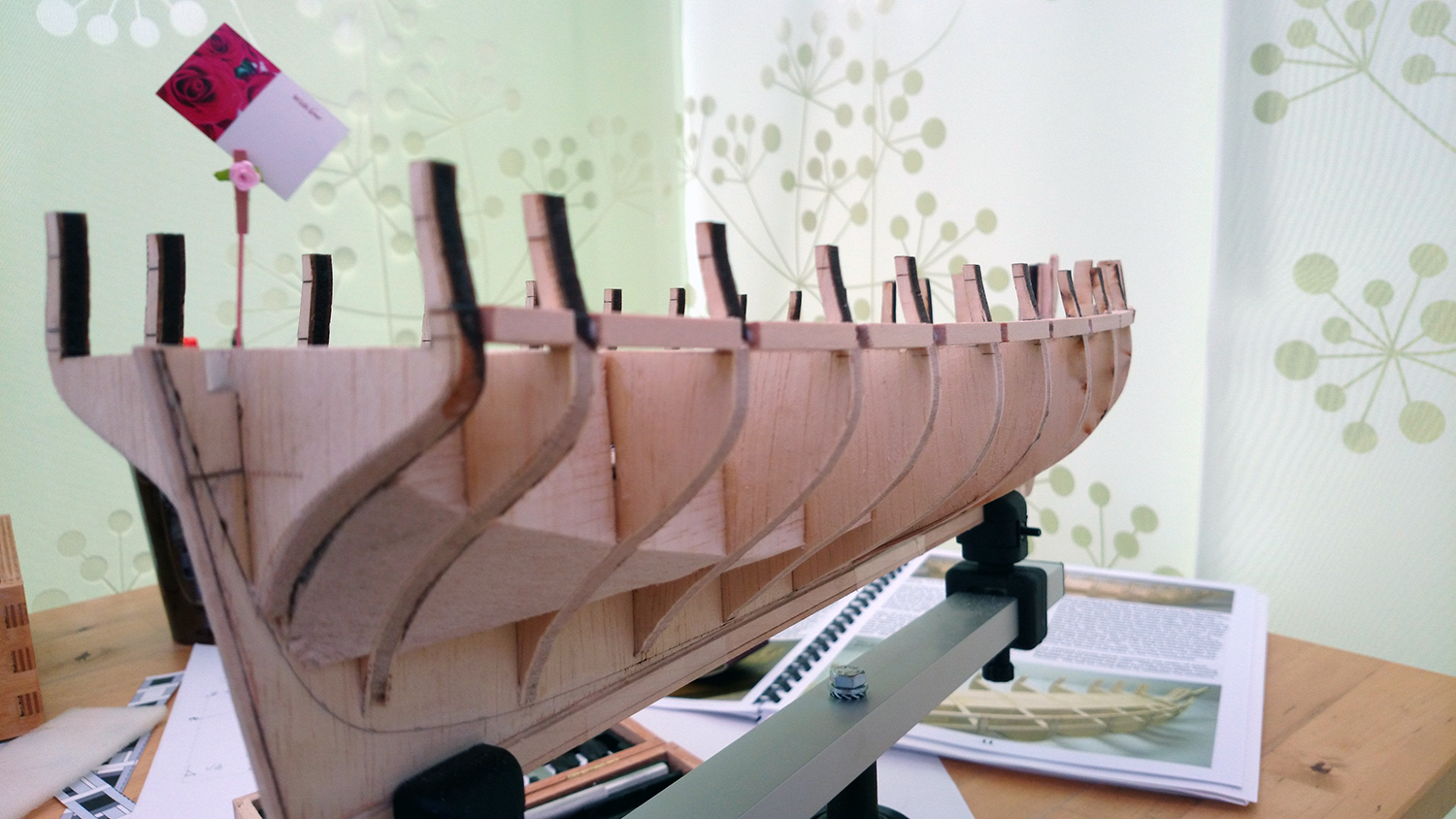
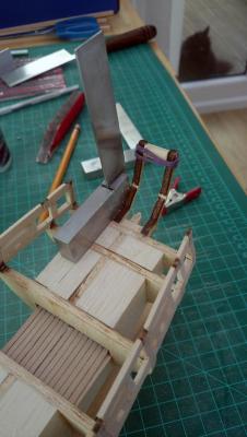
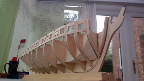
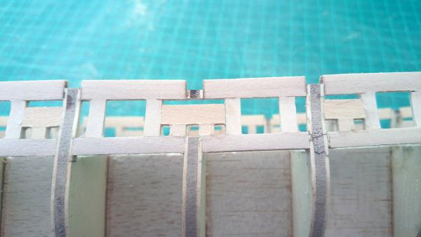
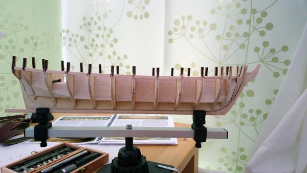
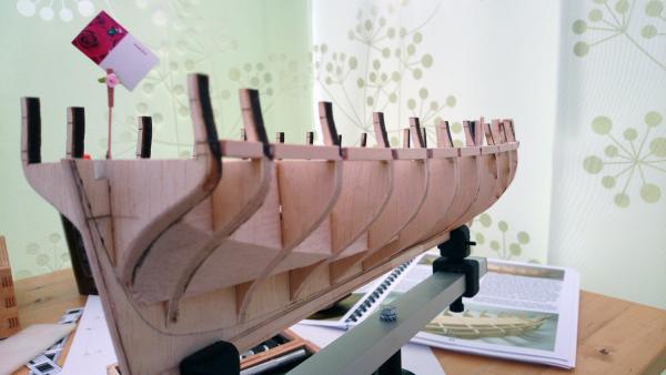
USS Brig Syren Part 7: Stern Framing Step 1: Verticals Taking the stern frames out of the wood was somewhat nerve-wracking. Having broken a fair few bulwarks already, I was only too aware how fragile the basswood is especially for pieces that are so thin. Nevertheless, I managed to cut them out unbroken and started cutting the fillers to length, using the provided template as a guide. Placing the first filler was dead-easy, placing the first vertical less so. I had to ensure that it ended up in the right position in three different planes, with little to go by. I set up a quick and dirty jig using an iron square to at least lock the frame in two different planes, with the third one judging by eye. Adding the next frame gave a further complication as it needed to up exactly like the previous one, whilst maintaining the appropriate distance between them. In order to achieve this, I stuck a temporary piece of width, cut to the appropriate length, between them and held it in place with a piece of plastic band whilst the glue dried up. I used this method throughout and achieved a result that I was happy with, without snapping a single one of the frames. Happy days! Step 2: Horizontals Before I started adding the gunport sills and lintels, I noticed that the tops of the stern frames were not 100% aligned so I clamped a temporary batten in place to completely line them up before I taped the template in place using the laser markings as a guide. Before I started glueing the spacers in place I remembered that a few chapters down the line a cardboard cannon was used to judge the appropriate height of the gun port sills. I think I remembered this as at the point of reading it I didn't quite get why it was done at such a late stage with everything already in place and no ability to make any adjustments. Therefore, I quickly knocked this up and tested the laser-markings for the gunport sills and noticed that they didn't quite sit in the right position. The gun would have some clearance from the sills, but it would be absolutely marginal and ideally the gun would sit in the middle of the gunport. I rechecked my measurements, but the only thing that I think I could have done wrong is that the whole stern is slightly twisted towards the bow, thereby lifting it somewhat up. It approached dinner time anyways, so I left it there and thus giving me some time to mull things over. I am not too worried about it, by dropping the lintels and sills somewhat I should be able to achieve a good clear finish with the cannon in the middle of the gunport. Still, any thoughts are appreciated! Kind regards, Martijn.

-
Thanks. They are two boys we found out today... guess I'll have some shipwright apprentices. ;-)
-
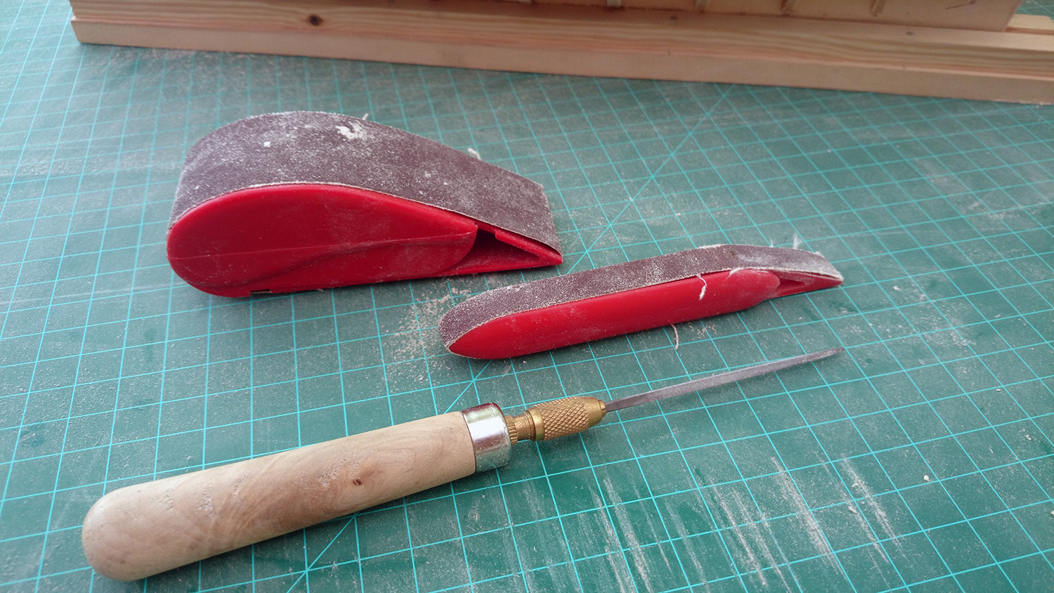
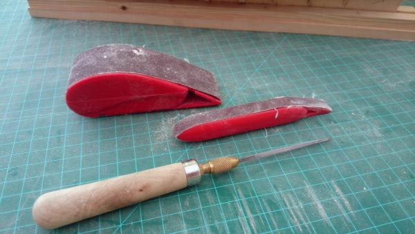
@Thomas: Thanks! It'll be some time before I can even compare to your fine craftsmanship, but I'll take the compliment nevertheless! ;-) @Tim: I bough them from a UK-based company called Cornwall Model Boats (http://www.cornwallmodelboats.co.uk/acatalog/fl6040.html), but given that you're USA based that may be problematic. Apparently, they're called Modelcraft Sanding Blocks, so perhaps something closer to home has them? Good luck finding them!
-
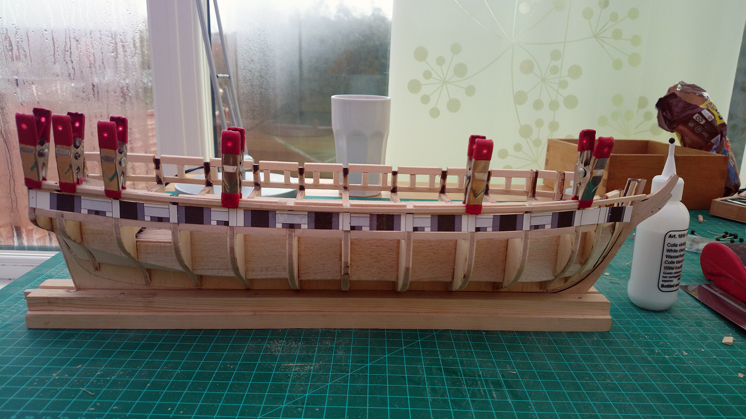
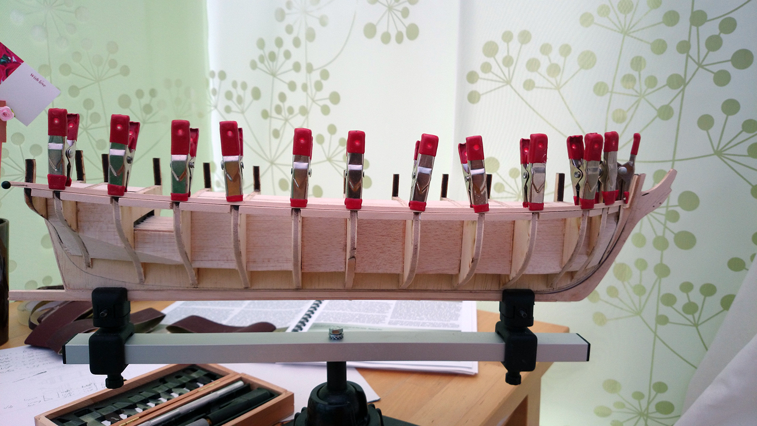
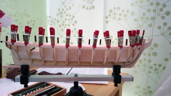
USS Brig Syren Part 6: Gun Port Lintels and Sweep Ports Step 1: Gun Port Lintels For the gun port lintels I used the same approach as for the sills, as in that I ignored the templates and got a temporary batton in place. I've read on various other blogs that they with their lintels they had them glued in the right place, but then when they checked a while later gravity had taken it's toll and they were no longer in the right location. Therefore, I decided to align the top of the temporary batton with the bottom of the lintels, so the lintels could somewhat rest on the temporary batton. Given that that the natural flow had been established for the sills, it was just a case of replicating this flow for the lintels whilst bearing in mind that a distance of 15/32" should remain between them, as that's the height and width of the gunports. I toyed with making a 15/32" block of wood to get this distance consistent across the whole run of the ship, but instead reverted back to my trusted calipher. I basically used my calipher to quickly mark the appropriate distance by hand, clamped a temporary batton in place and then re-measured with the calipher and adjusted. Once the distance between temporary batton and gun port sill was perfectly 15/32", I double-checked the flow of the batton before I started placing the gun port lintels. Step 2: Sanding With the lintels and sills in place I felt that the bulwarks were now sufficiently supported to take some serious sanding. I was still somewhat apprehensive, given that I had snapped a fair few previously, but it was remarkable how strong the ship now had become. Still, a fair bit of sanding had to take place in order to ensure that the bulkwarks would end up as 3/32" below the railcap and 1/8" thick at the deck level. I tried various tools, including electrical ones but at the end of the day nothing beats some elbow-grease I found. The outside of the ship was rather easy to sand as you had easy access and the curve of the ship helped, the inside turned out to be a completely different kettle of fish. Luckily I had seen this problem coming so I ensured that the lintels and sills were placed as much as possible towards the outside, with as little as possible sticking out on the inside. Eventually I ended up using three tools over and over again. Especially the big sander turned out to be a life-safer on the sanding of the inside given it's many curved angles. Step 3: Sweep Ports After some rigorous sanding, the gunport templates started to line up very well but still I decided to used my own measurements for the sweep-ports and once again used my calipher to ensure that everything was at the right distance of each other. Step 4: More Sanding With the sweep-ports final sanding took place, once again by hand. It's imperative to constantly keep checking with a temporary batton to ensure that you're fairing the hull correctly for planking later on. I've completed the whole hull now and re-took measurements, it's now just a case of fine-tuning here and there. Off to Chapter Four - Stern Framing! Let's see how many of those little buggers I'll manage to snap! :-) Kind regards, Martijn.


-
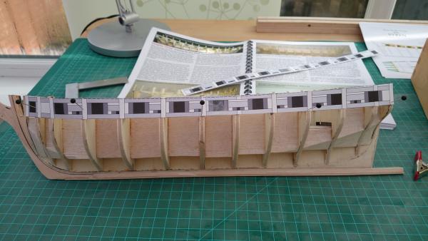
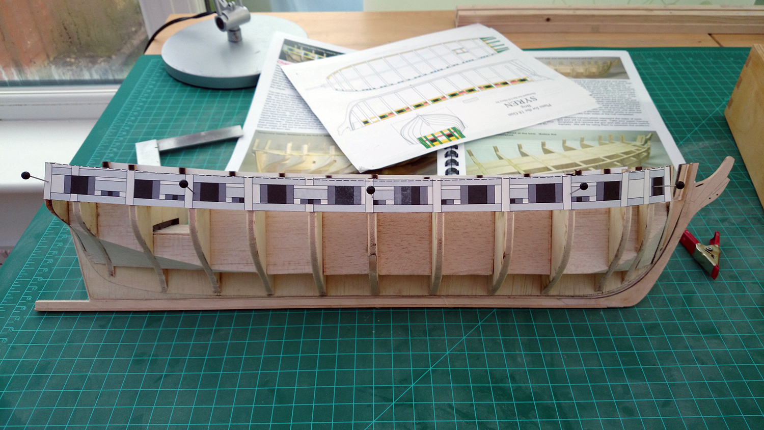
USS Brig Syren Part 5: Gun Port Sills Well, progress has been virtually non-existent the last month or so. First we had a bit of a heart-attack as at the 12 weeks scan the sonographer dropped a bomb-shell on us: "Well, here's your baby.... and here's your second baby." Apparently my girlfriend was laughing hysterically and I was white as a sheet. Very happy of course once it sunk it, but reading up and shopping takes a lot of time, and the little peanuts aren't even born yet. Drop on top of that a new job in London, so I'm away during the week, and time to work on my beloved Syren suddenly has become a precious commodity. Nevertheless, today is a bank holiday so I've finally managed to complete Chapter Three. Step 1: Gun Port Templates As you would have read in my previous post, I was somwhat flabbergasted as the templates that were provided with the kit really didn't line up with reality, which was rather frustrating as I had spend so much time ensuring that my bulkheads were square to the former. Eventually it dawned on me that the only thing I hadn't done well enough was the fairing of the bulkheads, and that they needed some further sanding. I got on with it and eventually the templates started to fall in line. They still weren't perfect, but given that plenty more sanding will follow in order to line up the gun port sills and lintels, I didn't want to go too far at the first step. Step 2: Gun Port Sill Height Another thing that came apparent from the templates that if I followed the laser-etched markets on the bulkheads, I wouldn't get a natural flow but also that the vertical location of them seemed somewhat out of line. I flicked through the manual and noticed the following build-up from the top of the bulkhead former: - Deck planking: 1/16" - Waterway: 1/16" - Space between top of sill and top of waterway: 1/16" Getting the right vertical location of the gunport sills is critical, as otherwise at a later stage your waterway may be too close or too far from it, which will impact on the look of your finished model. So I quickly knocked up a little piece of wood that gave me the appropriate distance and scribed new marks on the bulkheads, ignoring the original laser-etched ones. Step 3: Gun Port Sill Flow With the new vertical locations marked on each bulkhead, I could tentatively clamp a temporary batton in place. From there on it's just a case of constantly checking it by eye from the sides to ensure that you have a natural flow. Key is that you don't try to force the batton in place, but try to let it run as much as possible how it wants to, bearing in mind that it doesn't stray too far away from your markers. It's a good idea to check the run from every angle possible. I found that once I had established a natural run from one angle, it didn't always feel smooth enough from another one. Once I was satisfied with my gunport run, I added a temporary batton on the port run. This is important as you don't want to start getting the lintel in place on one side, before you mirror it as closely as possible on the other side in case further adjustments are needed. I basically followed the same procedure as for the gunport side, and once I had established a natural flow I checked on the stern and stem to ensure that they ended up in the same position. Luckily, mine did. With some further measurements and minor adjustments and managed to get a identical run on both sides of the ship. Step 4: Gun Port Sill Placement I used a different approach from the manual when I started placing my gunport sills as in that I left my temporary batton clamped in place. After all the careful measurements that I had done to ensure a natural flow, I felt that I wouldn't be able to quite replicate that by marking the bulkheads, so instead used the temporary batton as a guide. This gave the benefit that it was really quick and easy to put the gunport sills in place, whilst it also gave me a great guide to ensure that they were level in the horizontal plane. Once I had left the carpenter's glue to dry overnight I removed the temporary batton and checked the flow of the sills from all angles. After that, it was just a case of replicating the process on the port side. Kind regards, Martijn.


-
Yes, he is and he's keeping a keen eye on every single Syren build log and is always happy to provide advice and guidance. The manual is also very very good. As a first time ship builder it has steered me through the process so far without any issues. There are also a plethora of Syren build logs out there, so there's always somebody at hand to help you. Chuck designed a few other models as well, such as the Confederacy.
-
I'm building the USS Syren from Model Shipways ( so far the kit has been excellent. I wish some basswood pieces were replaced with a bit stronger wood and some of the Britannia castings aren't as clean as I'd like, but I'm a bit of a stickler for detail. Price was reasonable, everything was there upon delivery and in good order, and the manual is outstanding. The seller ModelExpo also give a guarantee that if something is missing or breaks during build, they'll replace it free of charge with no postage costs. I've read in build logs that they even honor this commitment when people make mistakes themselves.
-
Looking forward to the update and the re-post of the older photos. I'm a few steps behind you so keen to follow your progress and learn from you.
-
Well, in my very very short ship modelling career so far I can't profess to be an expert whatsoever, but for what it's worth these are the lessons I've learned so far (I'm sure you've found these yourself though): - Think and plan ahead - Learn from other's mistakes but also their hints and tips - Measure, measure again and then once more - Always dry-fit before you glue. - Cut/shave/sand little and test often - Take a step back and check what you've done - Don't be afraid to deconstruct and fix any errors - And most of all... do not rush And like my father always taught me: making a mistake doesn't make you stupid, making the same mistake twice makes you stupid. :-) In spite of that, I'm guaranteed to make more mistakes as I go along. Enjoy the journey though, not the destination. In any case, I think your Syren turned out to be a true beauty. Thanks for the tip on the masts by the way, I would indeed more confident to drill a pilot hole now and get the angle right whilst everything you see at the moment will be hidden, rather than working with a drill when the ship is in a pristine condition. Will have to read that chapter again and bring it forward a bit. Good thinking!
-
Great idea, Tony. Will definitely do that in the future, want to buy a few more proxxon tools.
-
I've just bought five minutes ago the Proxxon 2-speed scroll-saw DS460 (http://www.proxxon.com/en/micromot/27094.php?list) on eBay with a view of using it for spiling my hull planks whilst in the future I can use it to cut out frames and other elements for POF. One of the reasons for buying this particular one is that it's incredibly quiet. Normally they retail for just over GBP360, but if you search you can find sometimes returned items. I got this one for GP241 because it had some vibration issues but it's been re-calibrated and as good as new.
-
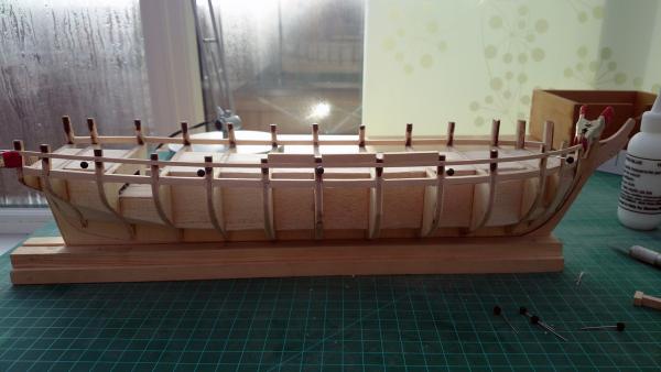
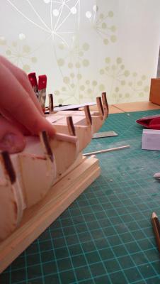
Minor update. I've installed the gunport sills on either side and consequently faired the outside of the bullwarks much more thoroughly, which now results in the framing templates to fall very neatly into place with only very minor misalignment. Very happy about that. I'll continue working on the port frames and make an update post once completed in the next few days or so. Kind regards, Martijn.
-
I was about to mention this. Also, as mentioned in that build log, there's a rather detailed Dutch log: http://translate.google.com/translate?client=tmpg&depth=1&hl=en&langpair=nl%7Cen&rurl=translate.google.com&u=http://www.vanhalterenweb.nl/modelbouw/%3Fcat%3D5%26paged%3D12 I'm intending to make the Friesland my next model, so I'd be keen to follow your build log if you do decide to go for the Friesland.
-
Ah, I wasn't aware of that Russ, thanks for the clarification. Perhaps less so what Andy is looking for so, but even better for me in due course as a first step into scratch.
-
Hi Andy, I've just started my first model kit which is a POB but after a few of these, like you, I would like to move to POF kits. I've literally been searching for this earlier this evening and one that might be of interest to you is the "Alfred" from The Lumberyard (http://www.dlumberyard.com/shipkits.html). For some reason their website seems to be down at the moment, but half an hour ago it was up so it may just be down for maintenance. They're not based in the UK (US based), but they are very well respected it appears, have well established kits and also provide wood upgrades for your kit (can choose from pear, boxwood and some others). Once I've build my ModelExpo USS Syren and Mamoli Friesland, I'll probably go for their Alfred which may then give me enough confidence to try my hand at proper scratch building. Hope that helps. Martijn.
-
Hi Larry, we're not too dissimilar I guess as I have a BSc and MSc in Civil Engineering which - as you can imagine - relied heavily on geometry and mathematics so I came to the exact same conclusion as you, hence why I spent so much time on squaring up everything. I seem to be spending much more time on the first few chapters than I thought i would, but I'm learning to hold myself back as it feels that these foundational stages make or break the model further down the line. Patience is a virtue! Get the bulkhead former straight, square the bulkheads, properly and evenly install the fillers, thoroughly fair the bulkheads and constantly check everything with measurements, templates and temporary battens and you save yourself a world of pain later on I'm hoping. These aren't the sexy stages as most of the work will be hidden, but as with structural engineering, get the structure right and the rest will fall into place. :-) On a side note, this is my first build as well and having looked at the photos of your Syren, if mine comes out half as good as yours I'd be a happy bunny indeed! Well done, Sir!
-
I can only aspire to achieve standards like yours... one day, hopefully! Truly amazing and inspiring work.
-
Thanks, Charley. It is a fair bit of extra work, but I think it'll be worth it. The problem with the supplied wood is that it's so soft that it doesn't hold a clean edge, which makes the pencil method somewhat unreliable I found. I must say, however, that your lower deck with the pencil does look very clean and smooth! I'm considering replacing the hull and deck planking with pear and will experiment some more with both options then. Will post my findings in due course...! Progress will slow down in the near future I fear. I'm currently at home waiting to start my new job on 24th March, so got plenty of time to spend on the Syren for another week. Then again, as somebody else said on this forum (and I'm paraphrasing): it ain't a hobby if it's rushed! :-) Also thanks for the encouraging words on the template, Charley. When I initially put them on I was a bit dismayed after all the careful work I had done before to ensure that everything is squared and lines up neatly. Now I'm fine with it. I do think that fairing the bulwarks will pull the templates more in line and there may indeed be some variation allowed in them. Worst case, I'll have to make my own templates which shouldn't be too difficult as it's all about evenly spacing out the gunports.
-
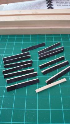
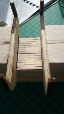
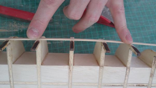
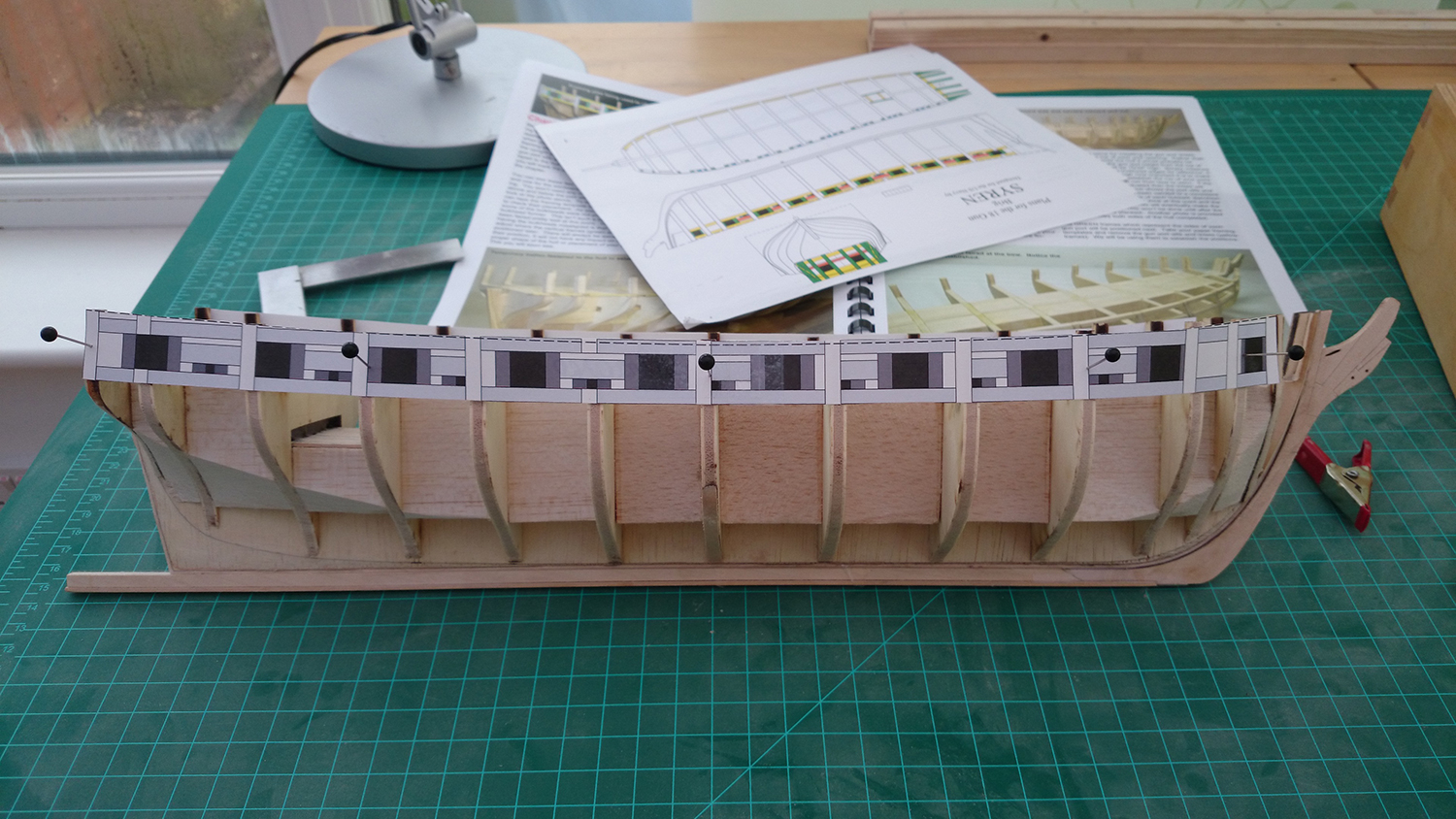
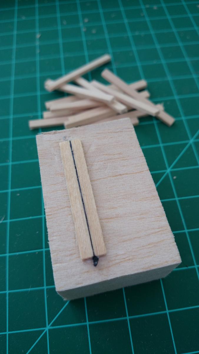
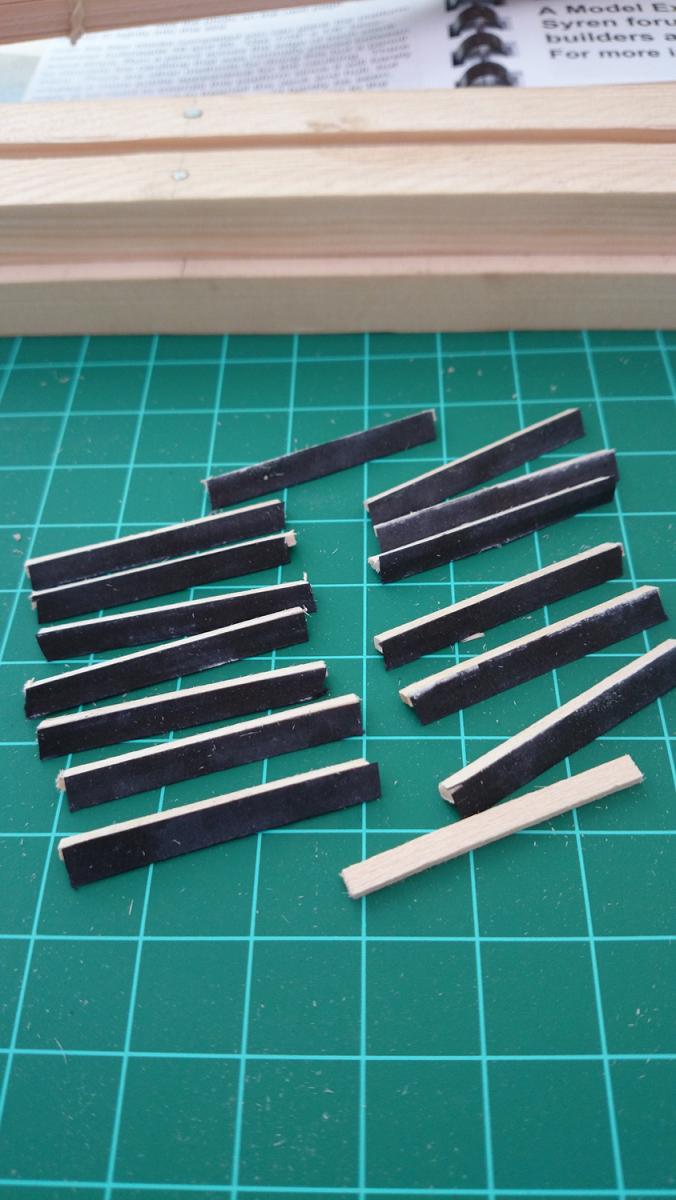
USS Brig Syren Part 5: Lower Deck Planking, Fairing, Framing Templates Step 1: Lower Deck Planking Whilst I was waiting for my home move and decided not to start on the Syren build until after the home move I've been reading lots and lots of build logs and have been mulling over a few things, one of them being caulking and how to simulate it. There are a plethora of methods, most commonly used seems to be marking the side of the planks with a pencil. This gives a subtle appearance, but not always uniform results. Therefore, I decided to build a mock-up with black paper between the planks. Given that I had no black paper, I took a piece of white printer paper and coloured it black on either side with a black felt pen. If you do so, make sure that you've got a water-proof marker otherwise it will bleed into the wood once you stain/lacquer the wood! I then glued a small strip between the mock-up planks, leaving it to stick out above the planking. Once dried, I cut the excess paper off with a hobby knife and sanded the planks smooth. This gave the following result: Happy with the results I decided the replicate this on the lower deck planking. If things didn't turn out quite as I'd hope for, nothing would be lost as this deck will be hardly visible once the model is completed. Given that the workspace between the bulkheads was limited and I've already snapped a fair few bulwarks, I decided to make life easy for myself and glued the black paper strip to the sides of the planking with a bit of carpenters glue before I glued them in-situ: Having left everything to dry overnight, I cut off the excess paper and then started to sand the planking down. Unfortunately, for some reason the dust of the black paper started to get into the soft deck planks, thereby creating a bit of a smudged appearance. I tried different grades of sand paper but eventually I realised that scraping the deck would solve the issue. I grabbed a hobby knife with a rectangular blade and although scraping didn't totally get rid of some of the smudging, it reduced it to such an extent that I'm fairly happy with the results. A few planks I didn't press sufficiently against each other, so the gap appears somewhat wider but where I have done it properly I really like the results. It's a bit more pronounced than simulated caulking with a pencil, but with a bit more practice I am sure that I can get the caulking virtually uniform. On the hull and deck planking I will also have an easier workspace, so I can minimise the sanding and use mostly scraping. All in all, a fairly successful test and I've decided to try this for the hull and deck planks later on. Step 2: Fairing Fairing was one of those tasks that I didn't look forward to. Not because I thought that it would be tedious or anything, but getting this right is so critical for the look and shape of the hull that I wasn't quite sure how to approach it. However, it was remarkably straight-forward, as long as you take things slowly and regularly check with a hull plank. In the middle of the ship, where the hull is fairly straight, I used a larger sanding block that cut across three bulkheads. Initially I tried using a sanding sponge, but quickly I realised that having a solid base for your sanding block is crucial. I mentally divided the hull into horizontal strips and sanded each one at a time, tackling three bulkheads at the same time and then shifting along one bulkhead. Where the hull curve became more pronounced, I could only tackle two bulkheads at the same time and at the bow, stern and near the keel I replaced my large sanding block with a much smaller one that allowed me to follow curves more smoothly. Don't forget that you have the laser-etched reference marks, although you shouldn't take these necessarily as the gospel. I decided not to fair the bulkwarks yet, until I will have put the gun port sills and lintels in place. I've snapped enough of them and with the gun port framing in place, hopefully they will have strengthened up sufficiently to withstand some sanding. The key thing to remember is to check all the time with a piece of hull planking. Given that this is a plank-on-bulkhead model, the joints between hull planks will fall on the bulkheads so having a good base to glue them against is critical. The hull plank should follow a natural run and then smoothly fall against the bulkhead. Where the hull curves significantly, you may have to twist the hull plank a bit or apply some pressure on it, but it should fall flat against the bulkhead in any case. Once you've checked all the bulkheads across the full length of each bulkhead, it is also important to check the full run of the plank. If you clamp it against each bulkhead, do you have a smooth run or are there some kinks or awkward bends in it? If so, now is the time to change this. The repair I carried out on one bulkhead previously because it was sitting 1mm too high worked out nicely and with some sanding I regained a smooth run of the hull. Step 3: Framing Templates With the fairing done I was excited to progress to the next chapter of the manual. However, once I've cut out the frames and put them against the model, they didn't line up at all. I checked and re-checked, measured everything up and checked whether my bulkheads are still square against the former but all adds up and there's no mistakes. I also read in other build logs that sometimes the company send the wrongly scaled templates, but I checked them against the A2 plan and it all matches up. My bulkheads are also square against the former and I rechecked this. In any case, it can't be the reason why they won't line up as the creep is nearly identical on starboard and port side: The only thing that I can think of is that the templates are pushed too far out because I haven't faired the bulkwarks yet, thereby introducing creep that gets progressively worse as you proceed along the hull. Any ideas are welcome though! Nevertheless, it doesn't stop me from putting a temporary batton in place in order to establish to run for the gunport sills and then to start working on the sills and lintels and subsequently fair the bulkwarks. Once I've done this, I can recheck the templates and see if the line up better. Watch this space! :-) Kind regards, Martijn.