AON
-
Posts
2,840 -
Joined
-
Last visited
Content Type
Profiles
Forums
Gallery
Events
Everything posted by AON
-
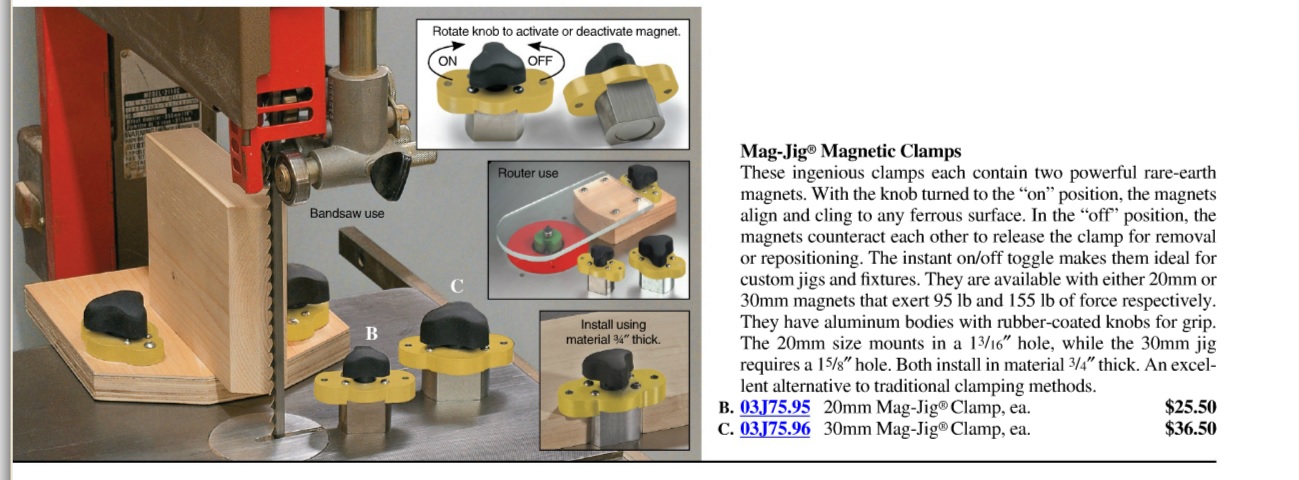
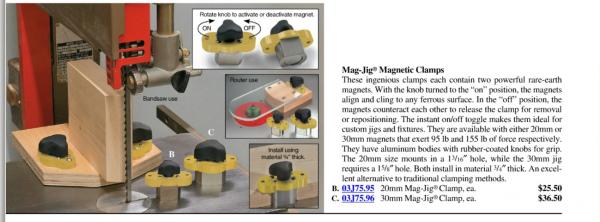
Below is a clipping from Lee Valley Tools These extremely strong magnets can be used for many different clamping situations Here they show it as a band saw blade support/guide
-

what is the ideal modelling table?
AON replied to AON's topic in Modeling tools and Workshop Equipment
Slab of Granite! I've just the thing (an old pastry board) collecting dust down in the dungeon. Great idea Thanks Alan -
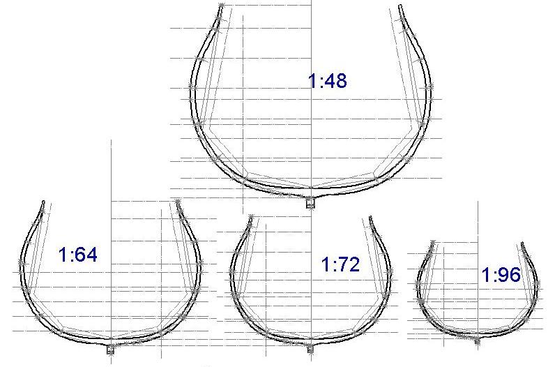
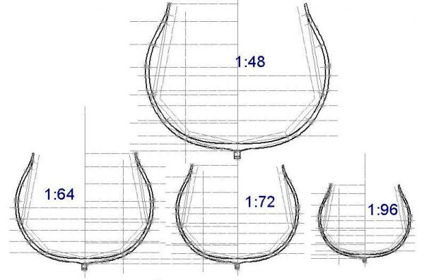
Thank you Mark Below is a visual aid for the different scales I created from my frame model section at dead flat Alan
-
My NRG mentor suggests I need to get off the fence and pick a model scale! Okay, he didn’t exactly say that (he is much nicer than that) but essentially that is what needs to be done. Well I have come to admit my reluctance to picking a scale…. I have trouble seeing the finish size in my head. You see in my line of work I envision the task in full detail (all the wee bits and pieces going together are revealed in full glory in my mind’s eye) and only then can I draw it. To do this I work in sub-assemblies. So how do I see the completely assembled magnificence of a Man Of War in my mind. Photos just don’t seem to be enough so I calculated the overall length stern to bowsprit, keel to tip of the main top gallant and width not being the full breadth of the hull but the length of the main yard. Then I picked the scales that I would consider working in and compared it all with tape measures on the floor and an old fashioned yard stick in hand. My rough estimated calculations yielded something very near 222 feet (67.7m) long x 215 feet (65.5m) tall x 99 feet (30.2m) wide at full size. At 1 : 48 (1/4” = 1 ft) = approx. 55” (140 cm Long x 54” (137 cm) tall x 25” (64 cm) wide At 1 : 64 (3/16” = 1 ft) = approx. 42” (107 cm) Long x 40” (102 cm) tall x 19” (48 cm) wide. At 1 : 72 (1/6” = 1 ft) = approx. 37” (94 cm) Long x 36” (91 cm) tall x 17” (43 cm) wide At 1 : 96 (1/8” = 1 ft) = approx. 28” (71 cm) Long x 27” (69 cm) tall x 13” (33 cm) wide In my mind smaller is going to be tougher to build but possibly more forgiving whereas larger might be easier to build but more revealing (warts and all). A 14” sided frame will be very near ¼” to 1/8” at the various scales. Tiny frames may be something to worry about…. Particularly as they only get smaller as you build upwards to the timber line where they are 1/8” to 1/16” sided dimension. Where to display my model years from now must be decided and has been my number one nagging thought since the moment I decided to move forward with this whole endeavour. The fireplace mantle is narrow; the foyer cabinet under my grand-dad’s picture in his RNNR sailor uniform is far too small; the cabinet in the den might be nice but I am just now thinking down in the dungeon area (basement) where I will be building the model might be the best location as inspiration for all other builds that might follow. If this is the case 1:48 scale is definitely on the table for consideration. I would very much like to hear from forum members about concerns with scale before I chisel it in stone. Comments? Presently I am creating the 3D image of my hull at dead flat and going to trim out a few frames just so I get a feel for it. Having tried revealed my hull is not so fair as I had hoped and so I will be back onto that. When is fair fair enough I wonder? Once again we are back to the issue of scale. I will be posting my Hull 3D images and steps to get it done hopefully by this weekend.
-
what is the ideal modelling table?
AON replied to AON's topic in Modeling tools and Workshop Equipment
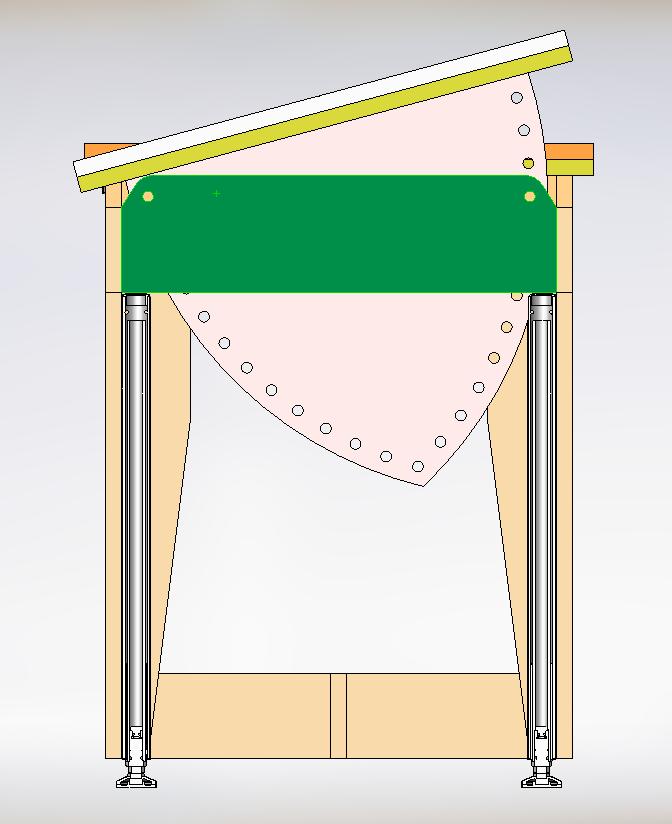
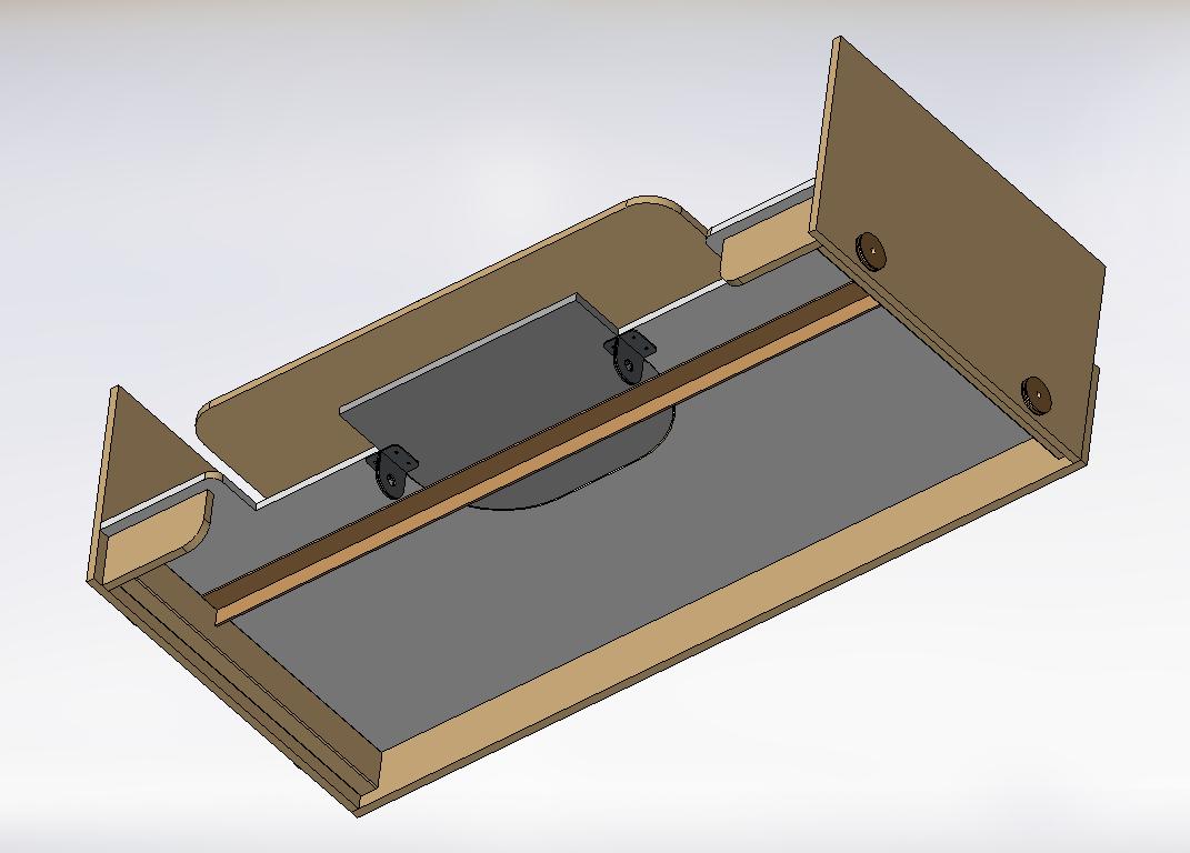
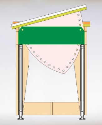
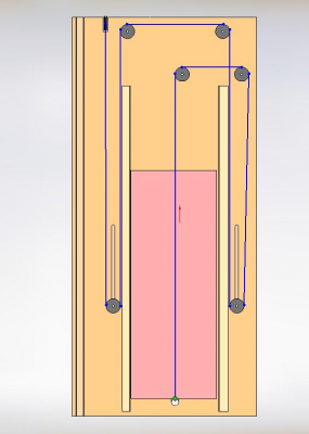
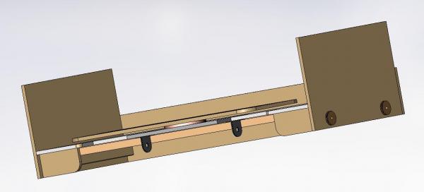
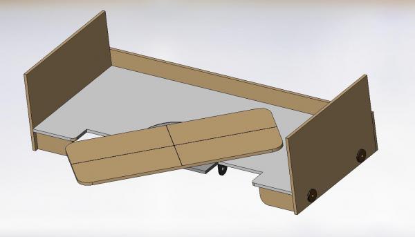
FYI - two additional section views of the manual pivot (let's hope nothing flies off the table my friend)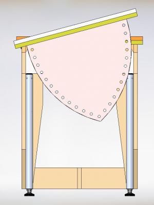
-
what is the ideal modelling table?
AON replied to AON's topic in Modeling tools and Workshop Equipment
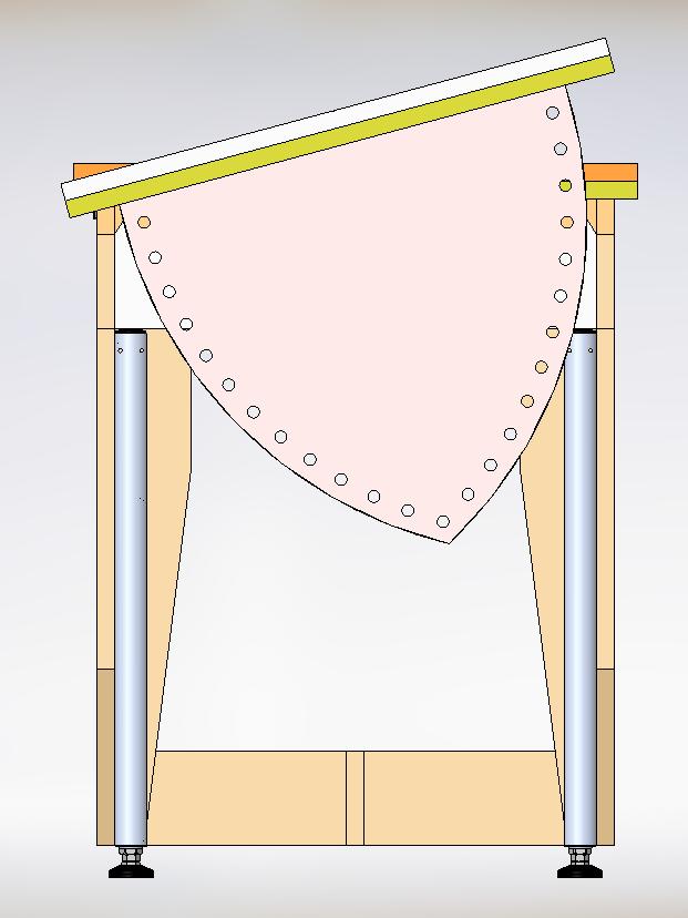
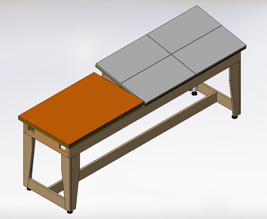
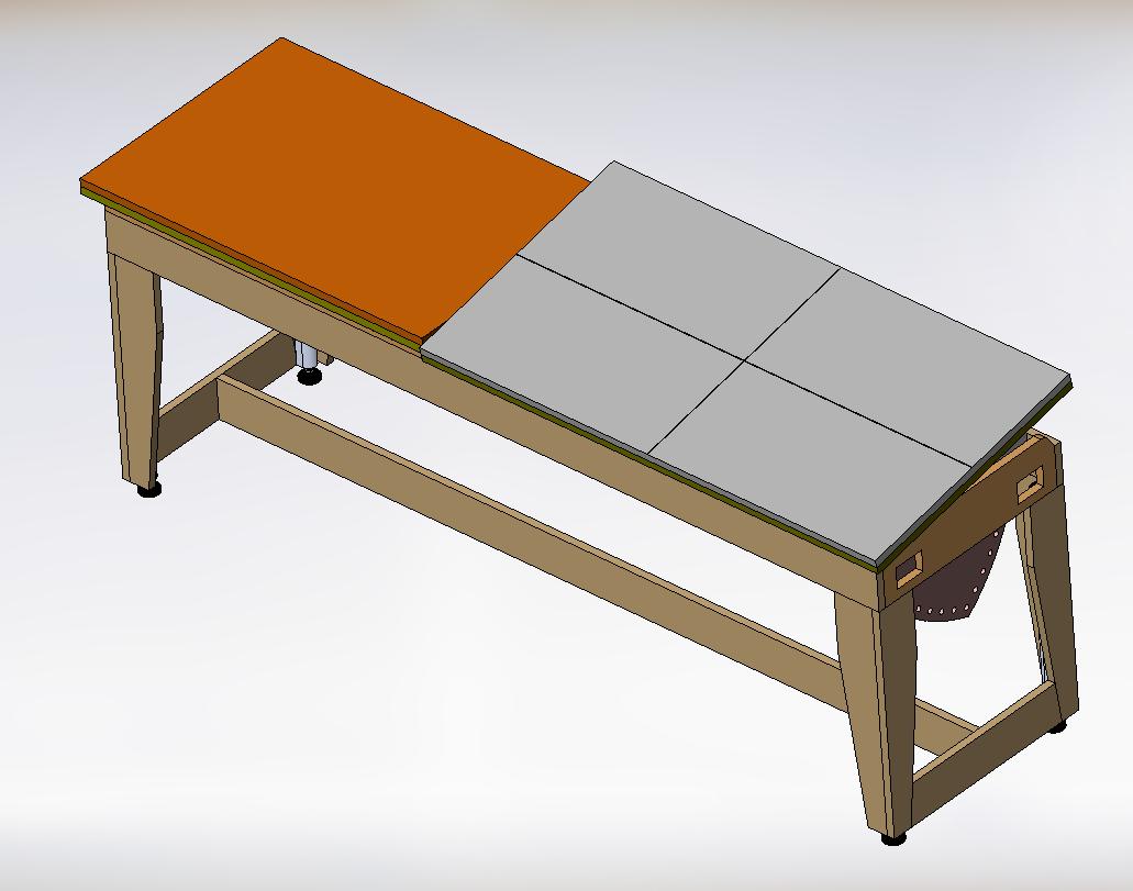
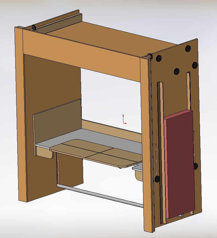
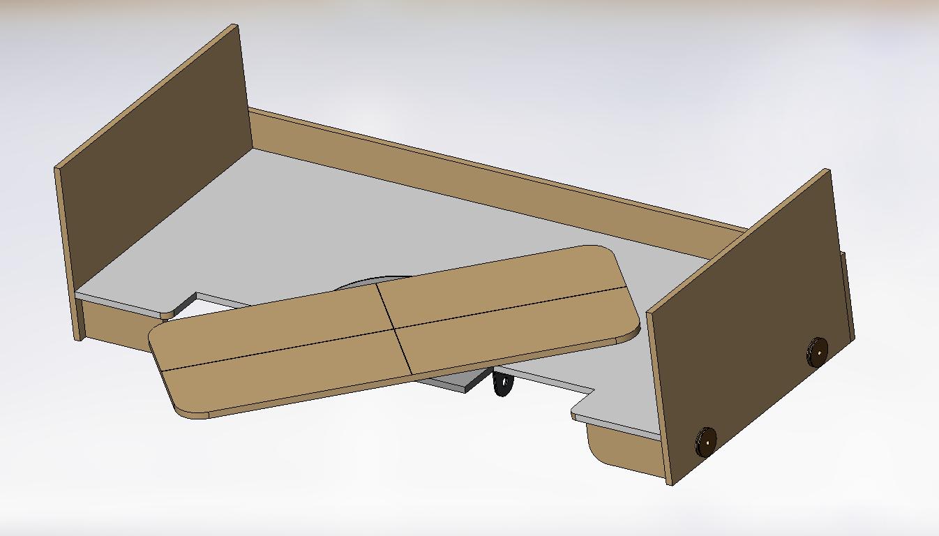
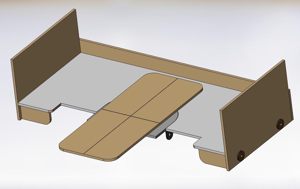
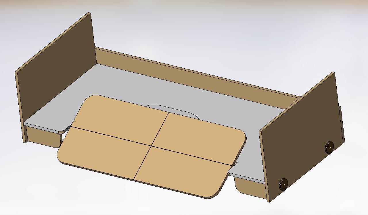
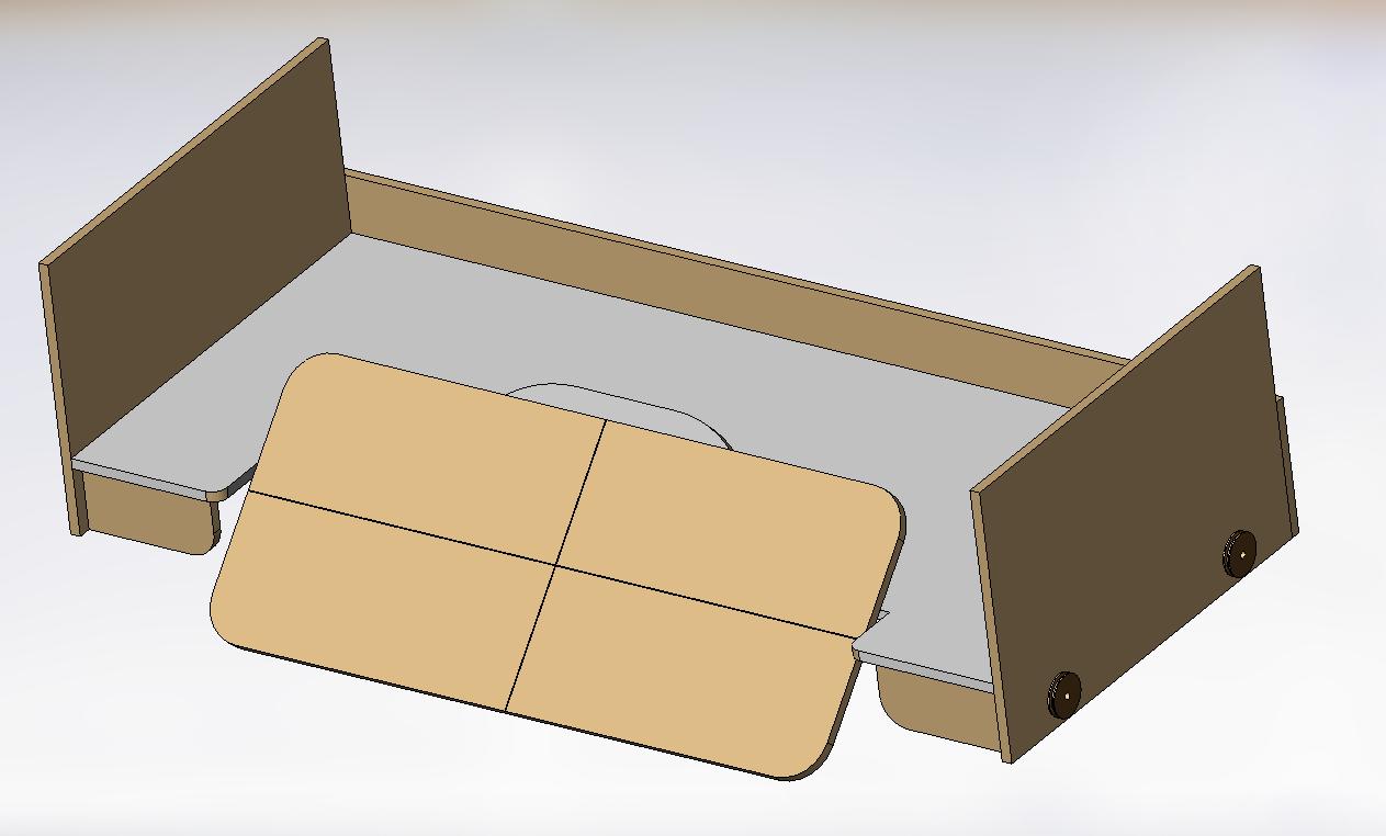
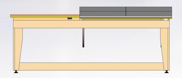
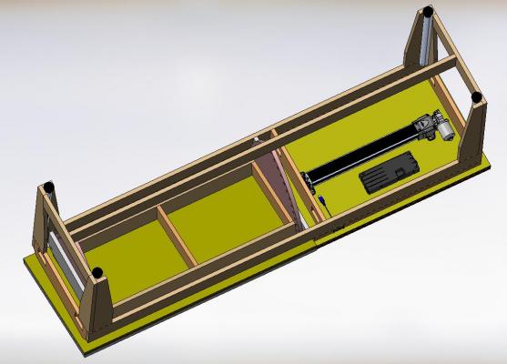
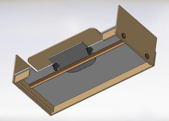
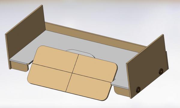
Here are four snap shots of the model I created for my movable, pivot top, walk around modelling table. *** If anyone see something amiss please let me know *** This table will adjust a full 15.7" (40 cm) in height from 29" to 44.7" (74 cm to 114 cm) The website says the lift cylinders require a minimum load of 35 lbs (15.8 kg) on each cylinder to operate and will lift 750 lbs (340 kg) total weight The darker looking table top area is stationary measuring 24" x 36" (61 cm x 91 cm) The lighter looking table top area presently pivoted measuring 24" x 48" (61 cm x 122 cm) The pivoting top will adjust in 5° increments from 0° (flat and level with the fixed top) to 60° It will pivot from either the front or the back (both ways, only one shown) I envision four simple sliding bolt pivot pins (not drawn up yet) to make this work. I intend to mount a sacrificial finished 3/4" (19 mm) plywood top on top of a 3/4" (19 mm) sub-base (total top thickness 1-1/2" = 38 mm) This means I can replace the finished top at any time via a few screws or bolts if every I need to. The four rectangular cut outs at the ends of the table frame are for electrical outlet boxes The underside view shows the pump/motor unit, controller box and button station Not shown is the wiring and flexible tubing that would connect everything The lift cylinders are mounted inside the four legs I've left the foot pads on as the supplier (SUSPA.com) did not have caster models or dimensions on their website Once I receive the items I can get the size of the caster and adjust my leg lengths if necessary No cabinet of drawers. I'll have to pick up a small rolling drawer cabinet later. I'll mount my florescent light fixture overhead off the floor joists (I'll be in my basement) I hope to receive the lift kit next week and start my table build in a couple weeks Will post photos then! Alan

-
what is the ideal modelling table?
AON replied to AON's topic in Modeling tools and Workshop Equipment
Bonjour Gaetan Thank you for the photos! Every little bit helps enormously. With my lower back problems leaning over or sitting for too long a period will be a problem, hence the adjustable height table top and also why I think the pivoting section will be handy. Alan -
what is the ideal modelling table?
AON replied to AON's topic in Modeling tools and Workshop Equipment
It took some doing but I've cleaned it all up considerably and yesterday purchased a motorized hydraulic table lift kit from SUSPA out of Grand Rapids Michigan (the local distributor in Toronto had me deal directly with the supplier via e-mail). I also purchased two locking and two non-locking casters from them. I'll be cleaning up my 3D model over the weekend and will post the results, Once I start building I will post some photos. Thanks again for the input and I apologize if I offended anyone with the way I originally felt about the cost of the electric lifts. Although they are not cheap they are clean and functional. It took a while for me to see the light. It can be tough to admit you might be wrong. (see what I did there?) BTW ... my table will have a pivoting section. Alan -
what is the ideal modelling table?
AON replied to AON's topic in Modeling tools and Workshop Equipment
Good morning all. I took the weekend to mull it all over in my mind Being honest with myself, my mechanical designer side loves the direction I am going. My practical side is telling me the "cabinet" is too bulky and lets face it ... ugly. My darling wife was very nice about it all but when I discussed it with her she quietly agreed with everything I said. I suppose she does know me very well after all, eh? I like what Mike suggests and Gaetan did... practical, mobile and space saving. Jud and Augie are correct, a table can be pulled away from the wall and walked around. If it is not too deep (as opposed to long) it wouldn't be an issue to reach across... so I could forget the turn table idea also. I cannot let go of the pivot idea as being practical and useful. I have all the wood and wood glue to make a table top and frame so there is no expense for anything but the fasteners, electrical outlets, wire, ground plugs and florescent bulbs for the fixture over head. It is back to the drawing board for something simple and practical.... and yes I have an idea! I did find another source for a clean add on lift device ( http://www.suspa.com/us/products/table-lift-systems/movotec-industrial-systems/ ) with a distributor in Toronto (1-1/2 hours driving from me - one way) and have e-mailed them for pricing of the bolt on and corner leg power lift systems. I am hoping they are reasonable. -
what is the ideal modelling table?
AON replied to AON's topic in Modeling tools and Workshop Equipment
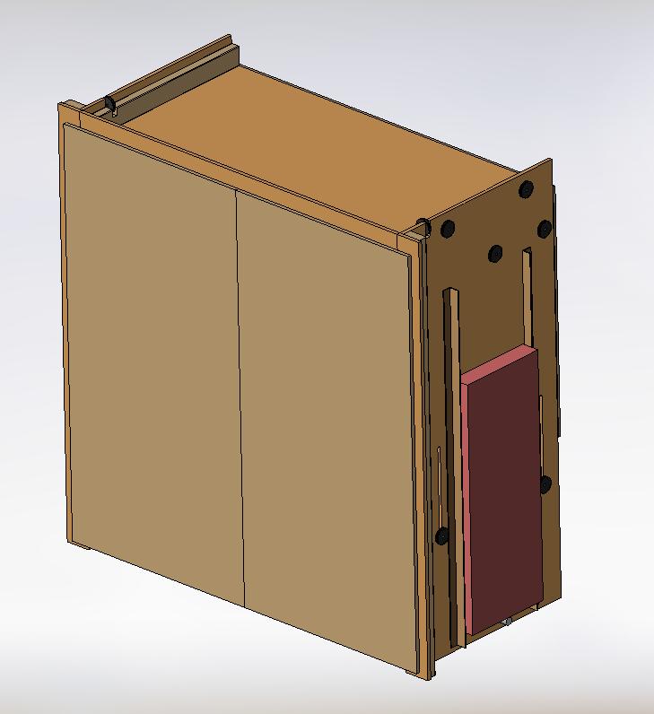
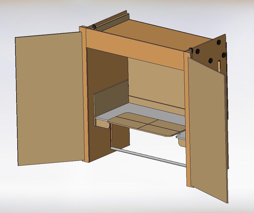
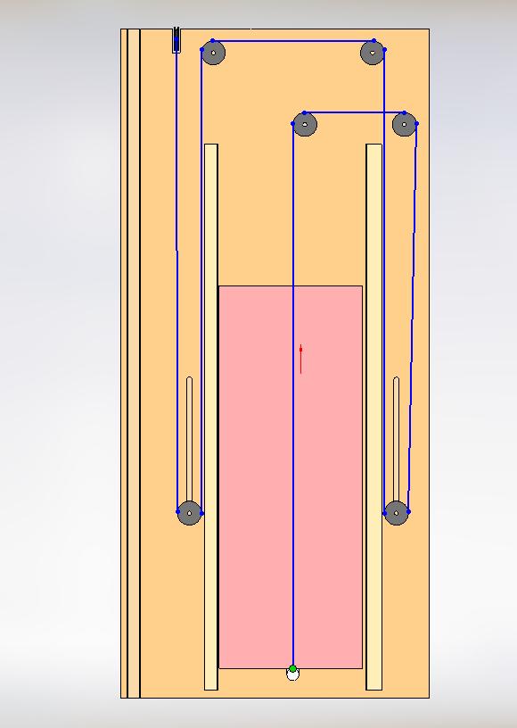
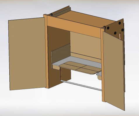
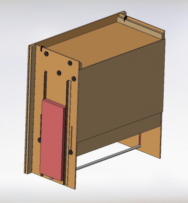
So here is the last half of my first "kick at the cat" (if you are a cat lover it is just a saying... I'd never actually kick a cat, they've been known to attack) 1. cabinet with doors closed (getting late so I haven't bothered with the OSHA rated outside enclosure of the counter weight) 2. doors open ( I can envision a roll out cabinet of storage drawers) You can see the table inside Fluorescent lights to be mounted inside on the roof towards the front (I have three or four 48" double bulb assemblies in storage ... do you think one of these might be too much illumination? Electrical outlets (not shown) to be on the front of the moving table, one double outlet on each side in the short apron under the table top Back wall might have a long metal strip mounted on it so I can hang drawings with magnets ... might do the same on the inside of the doors 3. rear view of cabinet The counter weight is outside (pink), one on each side to get adequate sand weight A cross bar on the bottom that ties them together (cable would go through the sand and secure to the bar Silicone can seal the cable hole Some guides on each side of the counterweight I put the counterweights on the side because if it was behind it pushed the cabinet out further, and it is out far enough right now. 4. side view showing cable run Although an engineering friend advised I need the cable run across the top from side to side... it just doesn't seem right to me. I think it should dead end at the top front cross pulley location and not run across from side to side. This would mean there are two individual cables, one on each side. I will need to experiment and see for myself. I just noticed a misteak ... the counterweight should be raised when the table is down! DOH! 5. Iso view of cabinet and table assembly with doors and back wall removed In this assembly the table lifts from 23.25 inches to 40 inches above the floor I see it locking / adjusting in about 4 inch increments or so Now I walk away from it for a while and chew on it for a bit. I'm sure to try to simplify it some. My darling wife thought I was just going to build a simple shelf type table off the wall... I thought she knew me better than that after 39 years of marriage

-
what is the ideal modelling table?
AON replied to AON's topic in Modeling tools and Workshop Equipment
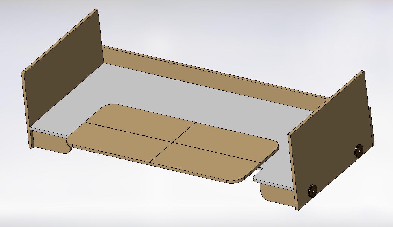
I've done a mock up of the table top The table top is 32" deep x 72" long The rotating top is 24" x 48" I'm thinking simple sliding bolts to lock all motions in position. working on the cabinet now All image descriptions on in the image title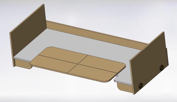


-
what is the ideal modelling table?
AON replied to AON's topic in Modeling tools and Workshop Equipment
My budget estimate for now Garage Door Pulley (Canadian Tire) $5.99 ea x 10 = $60 approx. 100 feet Steel wire rope (Canadian Tire) = $28.99 reg sub total $90 Say $125 with all hardware (clips, bolts, etc) and taxes and I have a mechanical lift (less the counter weight container ... beach sand is free) Knife Hinge 3/4 x 1-3/4 x 1/8 (Lee Valley) $33.30 a pair Aluminium 9" Lazy Susan (Lee Valley) $23.90 sub total $57.20 Say $66 with taxes and I have a combination rotating/swiveling model top Now I need to complete a drawing to get lumber and hardware cost for the desk and cabinet enclosure I'm going to guess a couple hundred bucks So for about $400 and some effort I might have a closing cabinet modelling work station I will keep you posted -
Solidworks framing help (please)
AON replied to AON's topic in CAD and 3D Modelling/Drafting Plans with Software
Thank you Don! Since I could not find the "staples easy button" for this in my SW reference book I was getting the impression I was going to have to redraw the inside of each station, re-loft and re-fair.... as I am not sure an offset matches the contract dimensions. Not something I look forward to but, as they say on the French side of my home town, c'est la vie! (But I'll wait to see if anyone else has a trick to share first) -
So I've drawn my stations, utilized the solidworks thin lofting feature to create the shell of the hull, completed fairing the shell. http://modelshipworld.com/index.php?/topic/5534-hms-bellerophon-by-aon-%E2%80%93-scale-tbd-%E2%80%93-1786-74-gun-3rd-rate-man-of-war-arrogant-class/ Now I want to add a varied thickness to the loft feature to simulate the frame moulded dimensions At midships these dimensions are: 21" cut down line (height of the floor timber over the keel) 12-3/4" at the heel of the 1st futtock/head of the cross chock 12-1/4" at the heel of the 2nd futtock/ head of the floor timber 11-5/6" at the head of the 1st futtock / heel of the 3rd futtock 11-1/2" at the gun deck elevation 12" at the gun port 11-1/2" at the upper deck elevation 5-1/2" at the timber line How do I add a varied thickness? Alan
-
what is the ideal modelling table?
AON replied to AON's topic in Modeling tools and Workshop Equipment
It is an extremely nice set up you have created but please tell me you didn't pay $1000+ for the base! I am going to get some pricing for pulleys, cable, swing hinges for the pivot top and a lazy susan type bearing pad for the rotating top. My gut tells me this will save me bags of money plus there is always the unmatched satisfaction of having built it from scratch. I have started a 3D model of the table tops and realize the rotating top needs to be raised to clear the fixed horizontal top when the pivot top is utilized. Will hopefully post something after the weekend.
-
what is the ideal modelling table?
AON replied to AON's topic in Modeling tools and Workshop Equipment
Good evening Gaetan, Could you please tell me where you ordered your lift from so I can check it out Merci Alan -
what is the ideal modelling table?
AON replied to AON's topic in Modeling tools and Workshop Equipment
Richard frame $470 - e-bay $769 Uplift $940 Livello (crank) $1439 Steelcase (air touch) Alan -
what is the ideal modelling table?
AON replied to AON's topic in Modeling tools and Workshop Equipment
not a very good endorsement just lost that warm and fuzzy feeling -
what is the ideal modelling table?
AON replied to AON's topic in Modeling tools and Workshop Equipment
Thank you - I would have never found this. as Sgt. Shultz would say ... Very interesting almost 20" lift (25.6 to 45.3 inch) 180 lb capacity 1-1/2" lift/lower per second 24Vdc $350 Cdn (incl shipping) for a pair with controller hmmmm................................. -
what is the ideal modelling table?
AON replied to AON's topic in Modeling tools and Workshop Equipment
I believe need to go through some distributorship to purchase one. Well I've done a web search and prices vary $US470 for a bare bones crank frame that they won't ship to Canada and onwards up to $US769, $US940, $CDN1439 If you have a better source I'd love to have it. -
what is the ideal modelling table?
AON replied to AON's topic in Modeling tools and Workshop Equipment
We have three at the office and they seem awfully expensive for something so simple Plus I want it cabinet like, to close up when I'm done for the day so I'd have to build around it anyway. Having said that ... I should take a fresh look at it -
what is the ideal modelling table?
AON replied to AON's topic in Modeling tools and Workshop Equipment
I was downstairs with the tape measure last night eye balling things and I believe the darn table top will be much too big for the space. Definitely need to start a scale drawing too get a better handle on the sizing. -
what is the ideal modelling table?
AON replied to AON's topic in Modeling tools and Workshop Equipment
Attached PDF is a hand sketch of the pulley and counterweight concept. I would consider using clean beach sand in a container as the counterweight as it is easy to add/drain to tune the balance (1cubic foot = about 168 pounds) so adjustment is practically effortless. Possibly lock the desk top it in place at the selected elevation (0 to 15") with a lever arm and pin on each side? Pulleys and cable all concealed in side walls and overhead valance. I will have to make up some proper drawings to build from. pulley sketch.pdf -
what is the ideal modelling table?
AON replied to AON's topic in Modeling tools and Workshop Equipment
Thank you all for the comments and suggestions. I just spent a half hour looking over "show us your work space" (very inspirational) at http://modelshipworld.com/index.php?/topic/6415-show-us-your-workbench-work-area and I am now convinced I am on the right track to keep the mess in the adjacent work room. Add to my short list - proper lighting / illumination - adequate power outlets over head - adequate storage - possibly a flip up wing table for reference books, sketches, bits and pieces or even pop corn - may be a cup holder - white flooring to find dropped pieces I've been mulling over the counterweight assembly in my head and am thinking of my old draughting board versus a pulley and cable lift base design we didn't use on an industrial design done years ago (we used jack screws instead ... but it was a few tons of load). Leaning towards the cable and pulley. If I can (time permitting) I'll freehand sketch something at lunch and post it. Alan -
what is the ideal modelling table?
AON replied to AON's topic in Modeling tools and Workshop Equipment
I have a walk around table with a backless and armless computer swivel chair in the work room and it can sometimes be quite uncomfortable for reaching and sometimes I just have to stand up for comfort and then I'm stooping over. I also use a higher stool to try to find some comfortable position at the low table and high workbench I have in there. I created a sketch during my lunch so you can get a better idea of what I'm thinking of dimensions are Imperial and metric (in inches and [mm] ) 4' x 8' sheet forms the table top table mounted up against the wall table top can raise any distance up to 15" higher so I can stand at it if I wish lift counterweighted and height adjustments lock with simple pin model mounts on offset centre to bring it closer to the front for a shorter reach model will rotate 360° on horizontal axis mounting table can rotate (tilt) towards or away from me up to possibly 45° (although I show 30°) to get easy comfortable access to under the hull or the deck haven't sketched supporting structure, etc as yet. still forming the idea (CORRECTED THE SPELLING ERROR ON THE SKETCH) MODELING DESK SKETCH.pdf