
HOLIDAY DONATION DRIVE - SUPPORT MSW - DO YOUR PART TO KEEP THIS GREAT FORUM GOING! (Only 75 donations so far out of 49,000 members - C'mon guys!)
×


AON
-
Posts
2,863 -
Joined
-
Last visited
Content Type
Profiles
Forums
Gallery
Events
Everything posted by AON
-
 Or the seal to the prop shaft is dry and tight?
- 71 replies
-
- 1
-

-
- Miss Adventure
- Model Shipways
- (and 2 more)
-
Golden Hind by Rock_From_Korea - 1:48
AON replied to Rock_From_Korea's topic in - Build logs for subjects built 1501 - 1750
They look pretty darn good to me! -
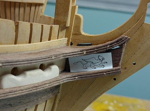
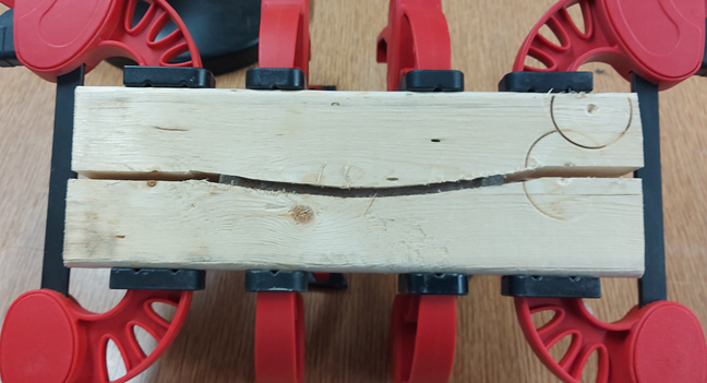
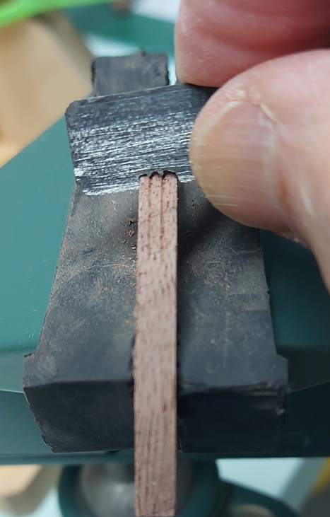
Well, I managed one of the two upper cheek finishing bits. It is presently soaking to be removed from the baseboard. I also installed the trail boards and decided on the figure, a griffon or gryphon if you prefer. The drawing has been mounted to some bass wood (linden) and that glued to a baseboard in readiness for carving. As I am getting tired of looking at my mistake at the stern, I've cut out the transom taffrail board in black walnut, steamed it, and it is presently clamped and drying. The clamp piece is a scrap 2x4 piece of lumber cut to the curve of the present stern taken with my profile gauge. I will not unclamp it until after Christmas. I intend to remove the offending counter timber tops sometime soon (in the new year) and will replace them with the taffrail board.
-
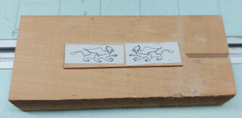
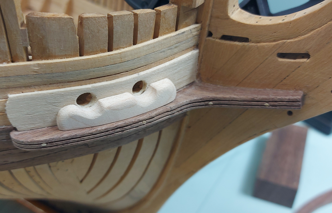
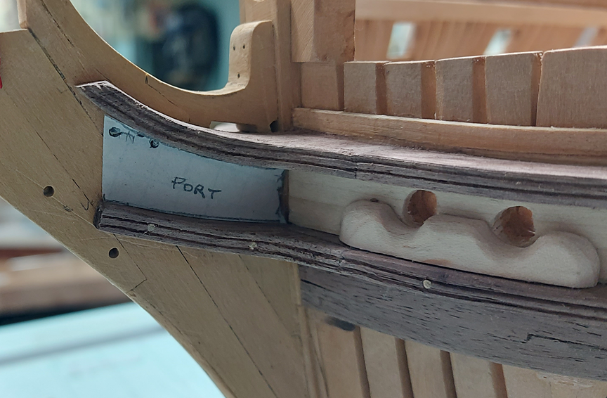
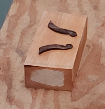
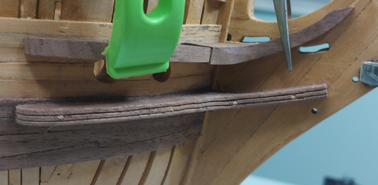
Having established the gap between the upper and lower cheeks, I made the hawse bollard and backing plate. I decided the clean white look of maple was a nice contrast. The backing plate was steamed and clamped. I couldn't get back to it for three days... it was quite dry and had no spring back! I completed shaping the upper cheek pieces, scraped the grooves into them, then glued them into place. They just need to be drilled and pinned similarly to what I had done to the lower cheeks. The paper template in the top photo is for my trail board. The contract reads as follows: To have a double trail board, and a lion or figure, as shall be directed. Handsomely carved; the rails and supporters handsomely wrought with mouldings. I searched the internet for lion figures and found a few that might be suitable, but then thought the Chimera monster (that Bellerophon killed) which is mostly lion… or a Griffon (as seen on the crest of the last stone frigate) which is partly lion might be more interesting, but also these might be more difficult to carve, especially to fit a ½” tall x 1” long space. Decisions! I also have had two attempts at the third piece of the upper cheek that rises up the main bracket behind the figurehead. These have both been tossed in the scrap bin. Third time is the charm! These two above had been soaked in 90% Isopropyl Alcohol (cotton batten soaked, laid over the figures and wrapped in clear cling wrap aka Saran wrap) over night to allow me to peel them off the block of wood. They were glued on with drops of yellow wood glue. The block is clamped in a vise to allow me to carve away at them. Not sure how much I'll get done before Christmas.
-
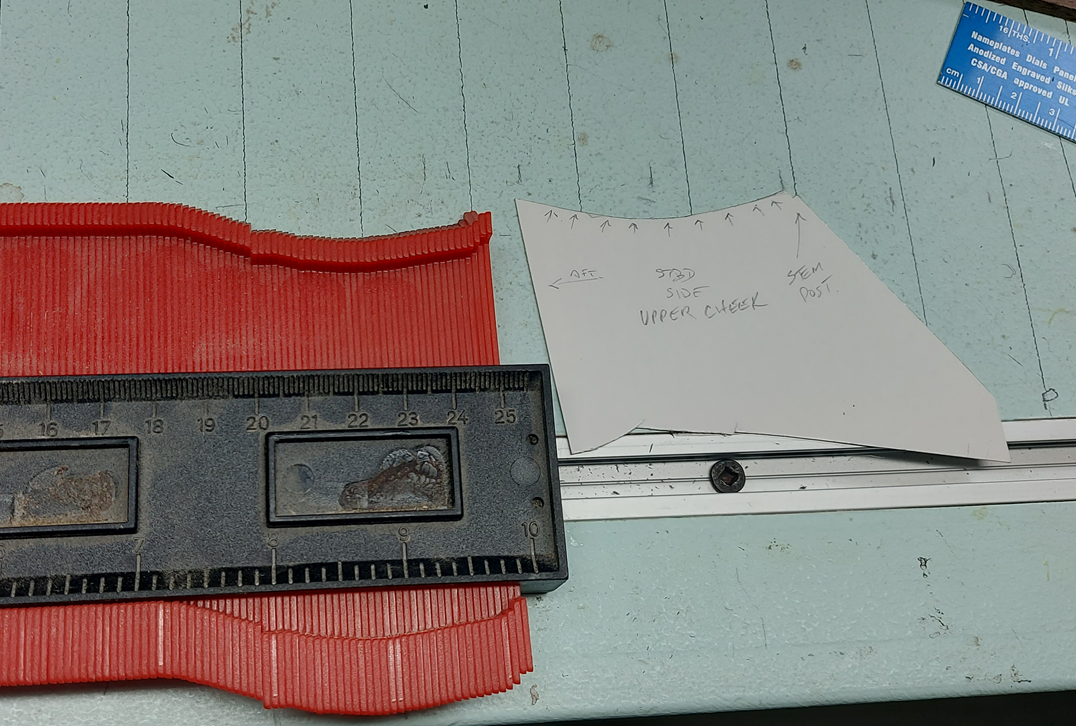
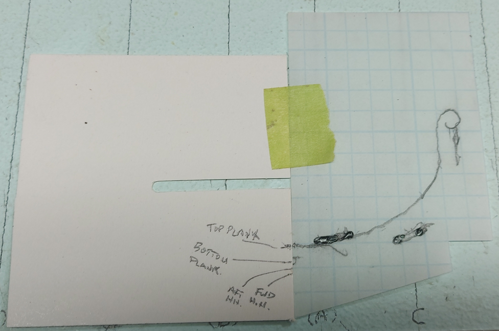
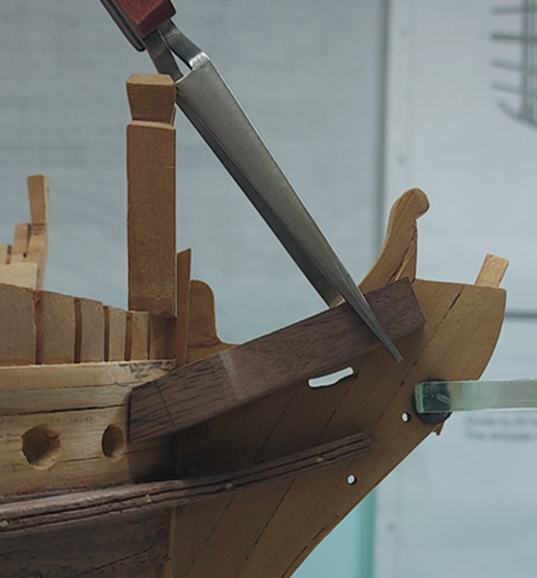
I had been working on the lower cheeks and have since started the upper cheeks. I began by making a card template of the hull using my profile gauge. Then I traced the stem works to fit the upper cheek between the gammoning slots. The lower cheek was made in two pieces, glued and pinned with wooden dowels requiring #57 drill bit holes. The upper cheek will be in three pieces of which I have two pieces roughed. The piece against the stem works is longer than needed. I will make the mating piece longer and trim the two to fit. Tomorrow I will make up the hawse bolster and backing plate pieces to help with spacing and alignment of the upper cheek pieces.
-
forgot to mention is was very cold this morning up here.
-
They can easily be cleaned up with a very narrow chisel, if you have one. If not, possibly I can bring you one 😃
-
Over take you? I hope not. Your build is one of the two I refer to religiously!
-
My first attempt at the lower cheeks was not a complete disappointment. Both lower cheeks were aligned with each other and a nice gentle slope on the forward arm. Made in two pieces... the joint wasn't quite good enough, even for me. 😁 My second attempt should be the keeper. Presently busy making one Christmas and one birthday present in the shop, on the sly, in between work on the cheeks. December is a busy month.
-
I think you need to sand those spots, finishing with very fine grade sandpaper (320 grit), and after a through cleaning, re-apply the shellac in those areas.
-
Golden Hind by Rock_From_Korea - 1:48
AON replied to Rock_From_Korea's topic in - Build logs for subjects built 1501 - 1750
The small details make all the difference. They both look wonderful! -
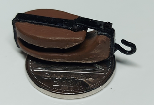
With a couple figures done and the three rows of 4" planking completed, it is time for a change before I go back to yet more planking. I decided to complete the assembly of my 3D printed viol/vyol block. The strapping is blackened card stock. The hook is copper wire that has been twisted and filed to shape. The completed block is placed on a 5cent piece for scale. I then started on the outer lower halves of the lower cheeks. Used some scrap pieces (of which I have plenty) for this first attempt. They fit up quite nicely. Still require shaping and rounding the edges. I'll need to make myself a scraper. Now to attempt the forward halves of the lower cheek assembly.

-
Not sure what I am supposed to see. I did sleep in so maybe I'll need a moment. A moment later.. I see it, the ring on the too of the lower capstan. Looking good!
-
It is wonderful to have you back. I hope you are doing well yourself. Looking forward to seeing more of your work!
-
Well there is always something to force you to change plans Yesterday, I started shaping the extension on the bow but didn't like where it was going, so I cut off the glue and started over. Last night it looked much better and I felt I wouldn't need to shape it. Just let it cure and then apply paint. This morning I got up, took a look at it and was quite pleased. Started working on something else and when I was done that I looked up and the whole extension from the strings out was gone! Couldn't find it anywhere. I must have knocked it. I cut the complete bow off at the hand and replaced the full length with a piece of bamboo. I'll paint that later today and pack it away.
-
You said: "This is going much easier then I thought it would". I always regret saying those words. Hope you don't! 😉
-
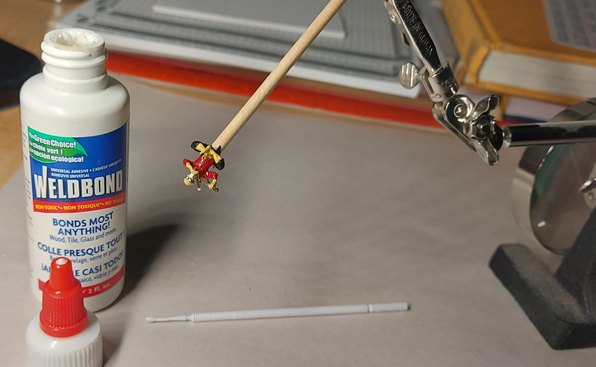
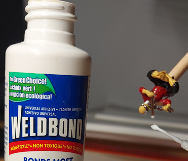
Worked on repairing the broken fiddle bow today. As the broken part is missing I brought up my bow stretcher from the shop. I keep it next to my sky hooks. 😁 All joking aside.... I use WeldBond to rebuild the missing part. I suspend the bow vertically downwards so I have gravity working for me. I applied a drop to the broken end and let it dry for about 20 minutes before applying another drop. It slowly grows in length 1mm at a time! Once I have it long enough, I have to let it cure (dry and harden) for 24 hours. Tomorrow I with break out the sanding board and gently file it to shape. Finally, it will get painted and after another couple days (to let the paint dry thoroughly) it will get a matt spray sealing coat.
-
Well, that's enough for one day. I don't know when the tip of my bow broke off. They are quite delicate. Guess I'll lengthen it tomorrow.
-
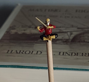
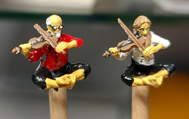
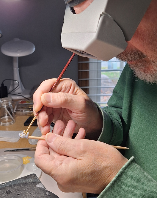
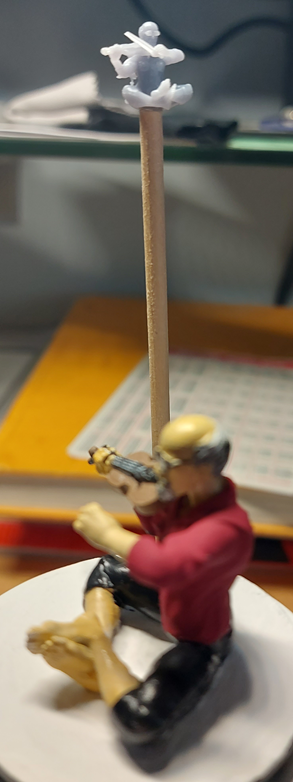
Use a extra good fine brush. A dot of paint on the tip. Spread a little on. Wet the tip of the brush and dab it on a paper towel then brush what you applied to smooth it out. Let it dry before touchups. I mounted the little fellas on a dowel using a drop from a hot glue gun and use the stick or a finger from my one hand to steady my other hand on. Don't forget magnification and good lighting.
-
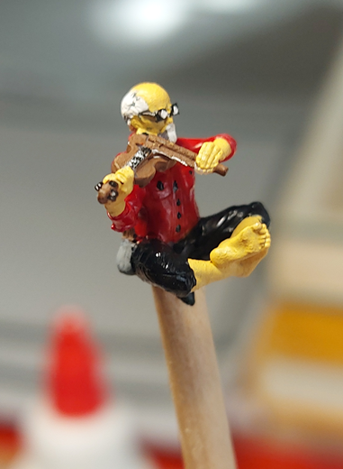
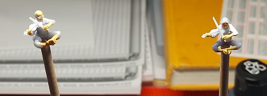
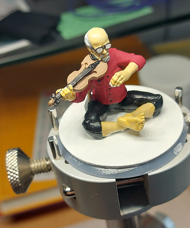
On August 21st this year, I had posted a couple 1:64 scale 3D figures that were made for my build. Today I decided to paint one large figure to "get the hang of it". A practice run if you will. This figure is a larger version... of me with my fiddle. I had broken the bow off so had made a new replacement (wooden bow and hair from my shop brush). The bow was removed for painting. Acrylic paints and brushes. Letting it dry for a day or two before I give it a protective spray matt sealer coating. I was going to do my plaid shirt but that is too difficult to replicate. I was also going to add a small tuft of hair on my dome but, what the heck, I'm certain I'll get there one day soon! 😉 Now having "mastered" that I feel I've learnt nothing when I put the 1:64 scale mini me next to it. I'll give him a go tomorrow.
-
Need small repair done on jibboom of Le Superbe model
AON replied to Mr. Matt's topic in Masting, rigging and sails
tmj's suggested repair above is the quickest and easiest! Once you wrap it with the cling wrap you might also apply a splint to hold the assembly in place using something like toothpicks and elastic bands or string if it is still on the model with rigging. Other option is to remove the pieces, drill both broken ends and insert a metal pin and epoxy them. The metal pin gives some additional strength. Alignment on a break has always been a problem for me. Another option is to remove the pieces, cut a slot through the two broken ends and insert a biscuit (wafer of wood) and epoxy it all back together. This is a little easier to align. I read you reached out to local clubs. Does this include the Model Shipwrights of Western NY located in Rochester? I might be able to help you contact them. PM me if you'd like some help. Alan O'Neill Model Shipwrights of Niagara (MSON) -
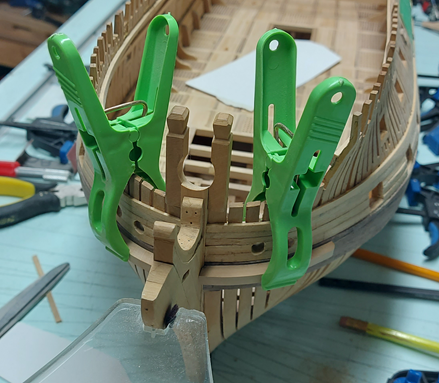
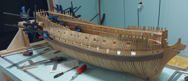
Working on the installation of some exterior hull planking above the main wales. Two rows of "thick stuff upon the wales". First row 6-1/2" thick, second row 5-1/2 inches thick. Now working on 3 rows of 4 inch thick planking above that. One row installed. Thought it best to get this on while I can still use my 4" bar clamps through the gunports. If I attempt this after the main deck is installed I'd be in trouble. Turns out it was a lucky thing I had to tear that deck out earlier.
-
Having done some for the MSON, I feel for you and the massive quantity of videos you've committed to indexing, but rest assured that everyone using them will appreciate the work. I hope you haven't committed to a deadline!
-
I would think a video log is better than any memory to allow you to physically see how you did something months or years ago!

