HOLIDAY DONATION DRIVE - SUPPORT MSW - DO YOUR PART TO KEEP THIS GREAT FORUM GOING! (89 donations so far out of 49,000 members - C'mon guys!)
×


AON
-
Posts
2,868 -
Joined
-
Last visited
Content Type
Profiles
Forums
Gallery
Events
Everything posted by AON
-
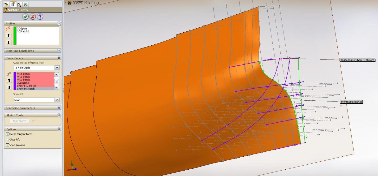
 Well! Should be easy.... right? I drew in two additional guidelines offset from the sheerline at 5 feet and 10 feet I then attempted to add them to the lofted feature. ERROR the guidlines do not intersect with the profile line JFTHOI I switched them from being guidelines to profile lines ERROR So I shall attempt to draw new guidelines that intersect with the profile line and see what new error message appears
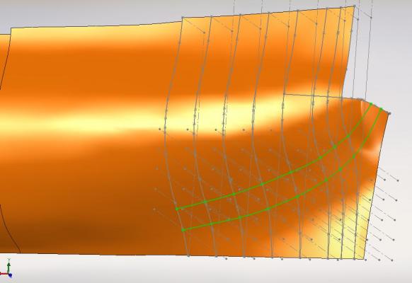
-
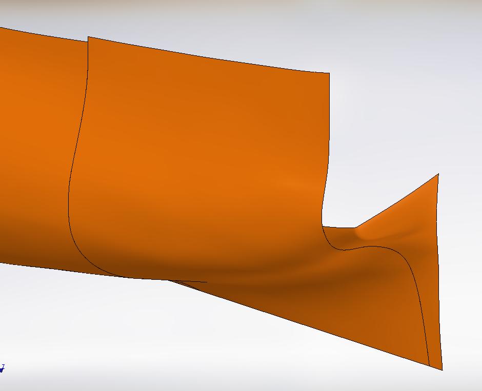
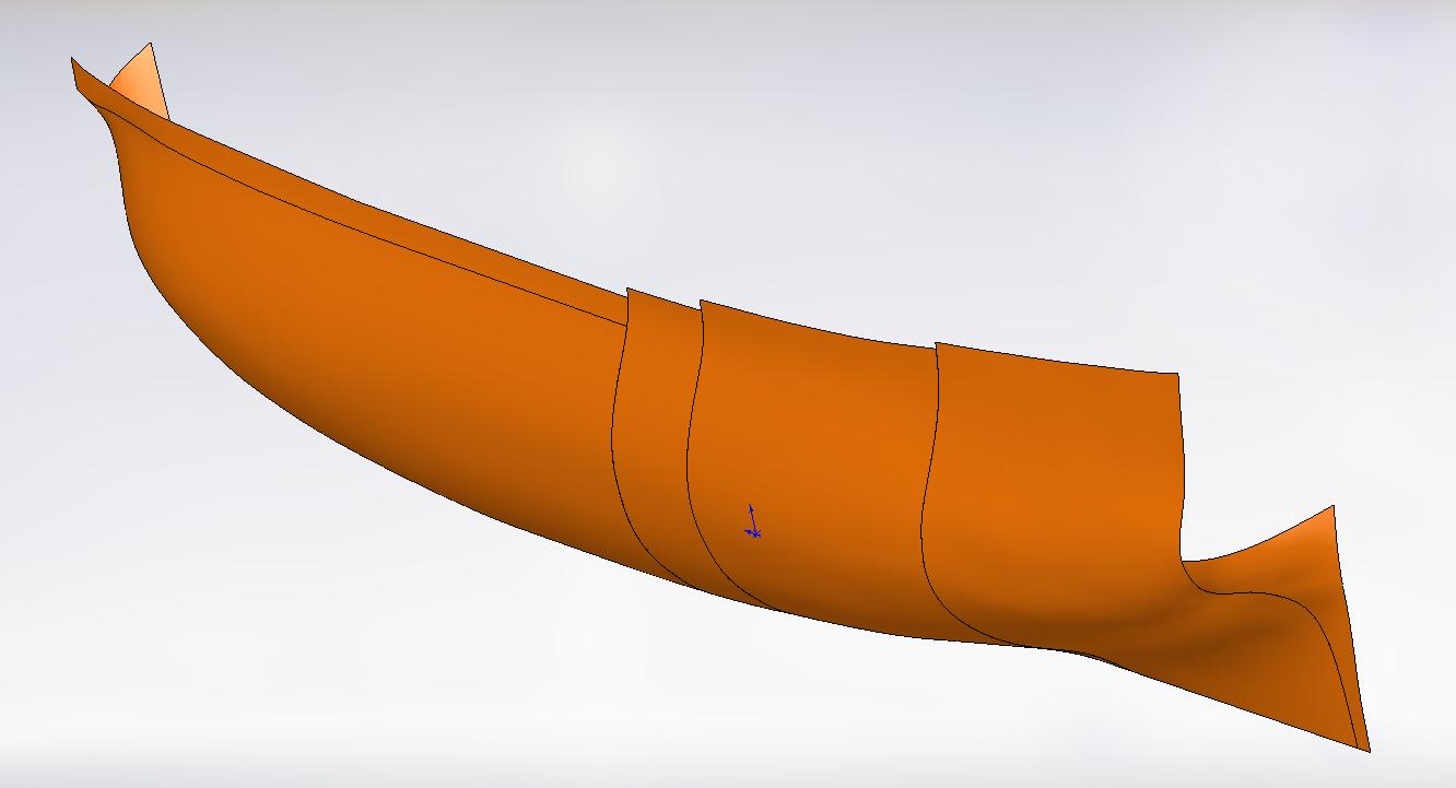
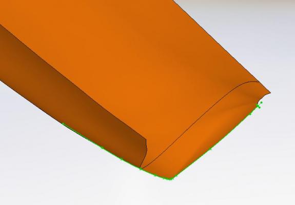
My NRG mentor is reviewing the whole model at the moment and I am certain he will have similar comments! I am late off to work this morning as I have a cracked tooth that will be tended to in less than a hour... so I have a moment to see the example. I see the sharp bend on the aft underside of the model you are referring to and I am thinking I'll need more guidelines to remove it. Hope to have an opportunity to tackle it tonight Thank you Druxey DON: I'm glad it looks easy! If I were better at this 3D stuff I might believe you
-
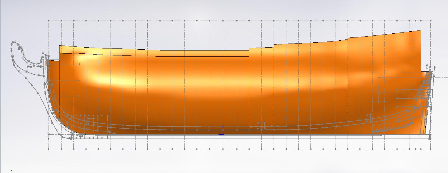
I've been busy with the expansion of my workroom and am now down to taping and mudding the joints. Then is painting and moving all the gear back in. That gets me that much closer to building my model. After looking at a few books, builds on the forum and my plans I think I understand the upper wing transom comment. I made adjustments by adding reference points and manipulating the guide line to the shape on the plan. here are the results. I'll have to get some of the dents out of the hull that I noticed at the stern before I start slicing the frames and making templates.... but I am that much closer.
-
at the moment it seems like it I am transferring from the almost 300 year old plans to a fresh 3D model in an attempt to create templates for material cutting....albeit it is going much slower than this old feller thought it would. Learning tons along the way.
-
Hmmmmmmmmmmmmm I'll have to take another long look at volume 1 of TFFM as there is a pretty good tutorial in it
-
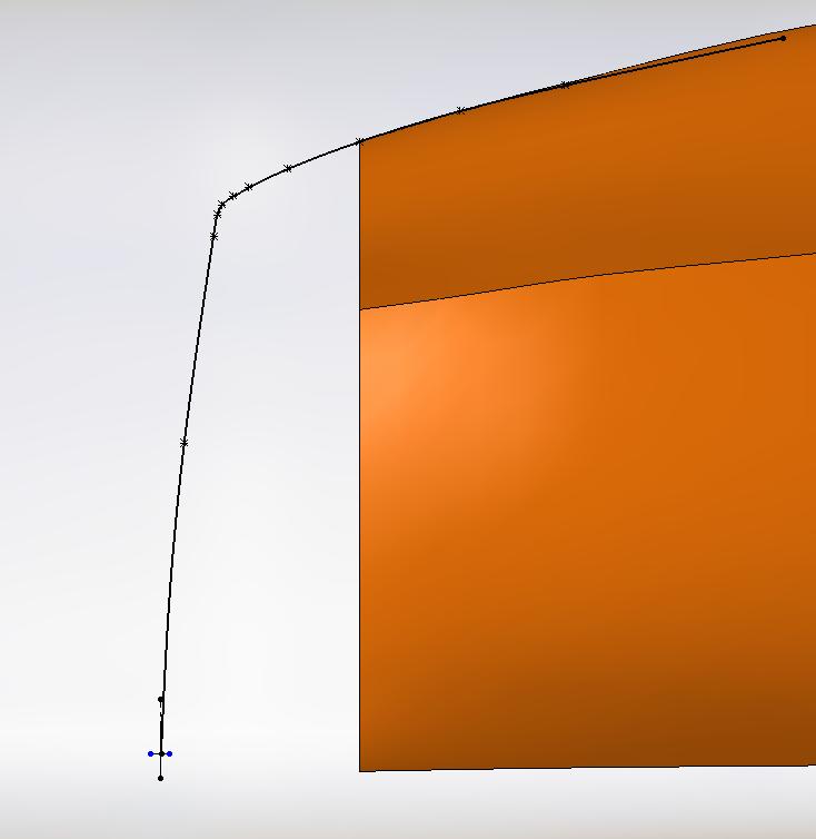
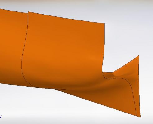
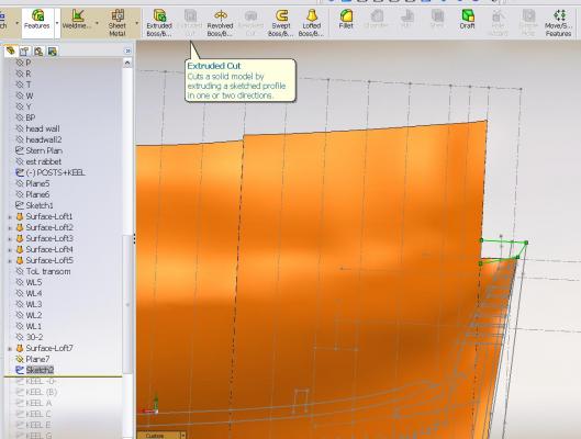
I now have two issues to deal with 1. the hull near the stern is not so "fair" and needs some tending to 2. the top edge of the lower transom should be angled or sloped downwards and it isn't I thought I would simple create a sketch and "extrude cut" out the slope You can see when I tried that the program does not give me the option to extrude cut I think I need to create a sloped plane to draw the upper guide line on so the lofted feature will end properly at the top edge but not now... time for breakfast and getting ready for the work day.
-
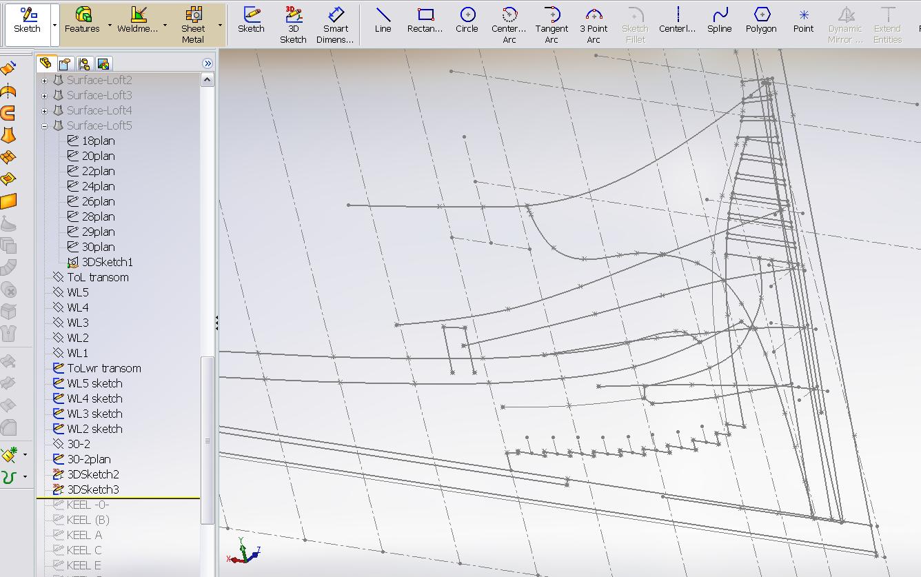
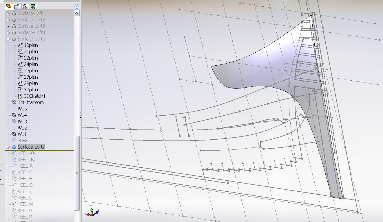
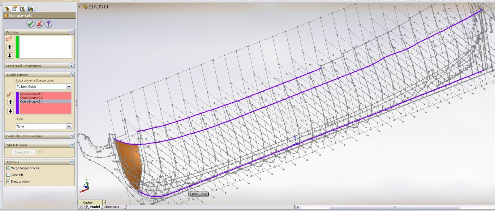
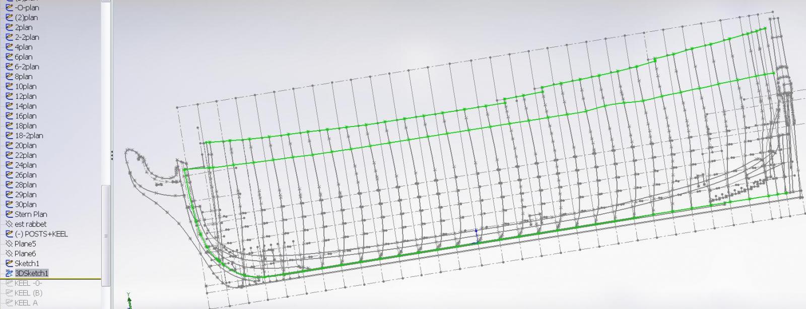
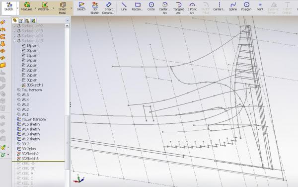
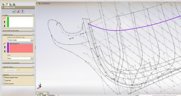
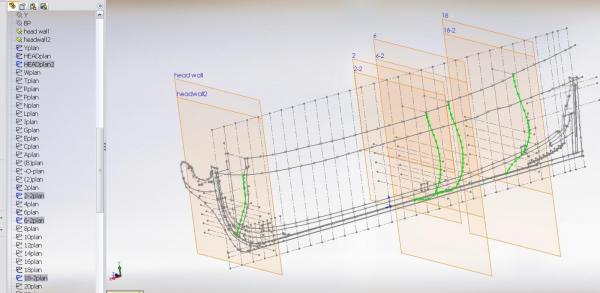
I turned of the distracting layout I drew a shortened station 30-2 I drew a couple more guidelines at the keel and stern post rabbet lines Opened a new loft feature picked my guidelines picked my profile lines and there it was


-
Good afternoon Hexnut and thank you for the suggestion. I think what I will do first is ignore the upper transom outline as I've pondered on it (off and on all day) and I think that is what is blocking my vision. If I try to loft the hull up to the upper most lower transom timber below the top of the stern post and see how she looks I might be pleasantly surprised. After all most of what makes up the upper transom seems like an after thought, "tacked on" like the officers "out houses" and sunset viewing "railed balcony".... they certainly new how to live!
-
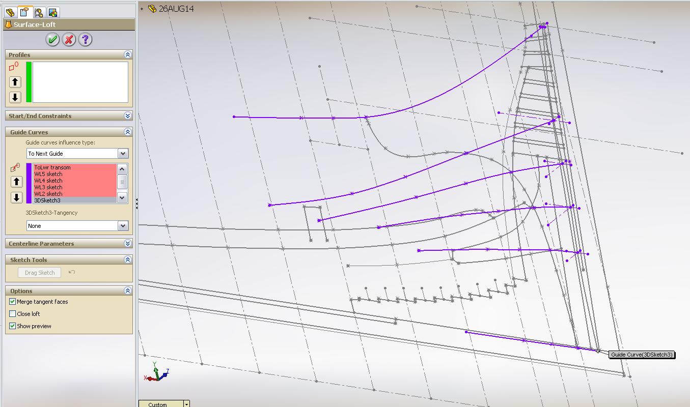
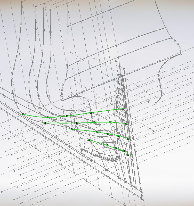
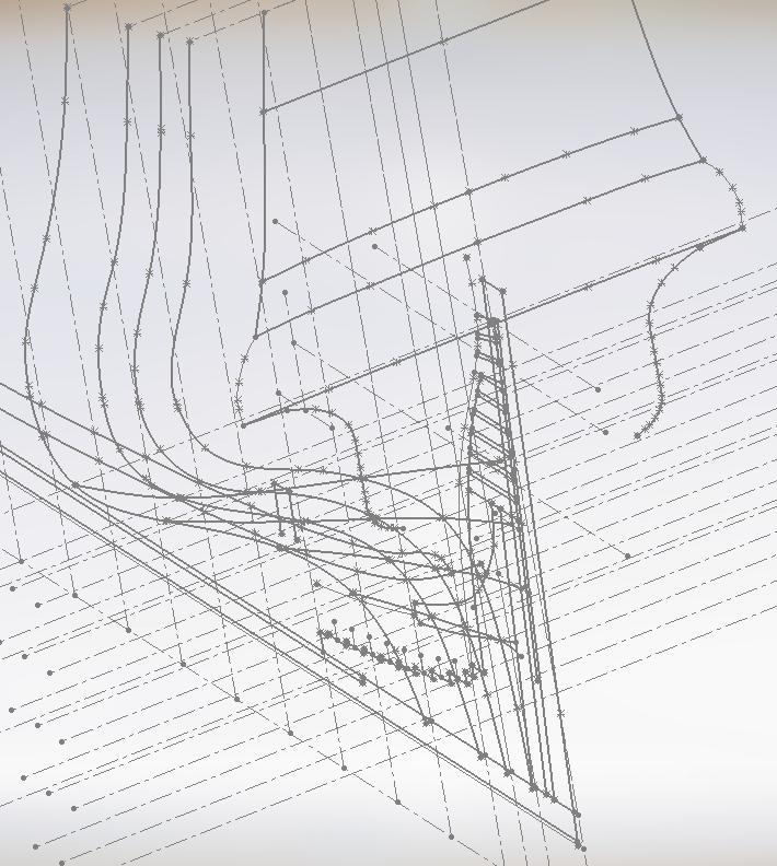
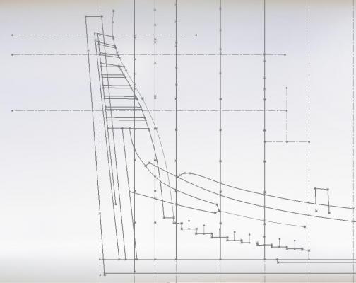
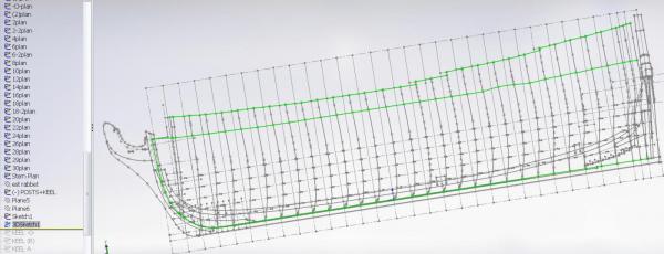
I've drawn in blending guidelines at the waterlines to assist in lofting the lower hull I've looked at great images in various books and photos on the forum of Vanguard and Bellona to understand the shaping of the lower transom timbers Just when I think it makes perfect sense I come to my sketches and the vision is gone! I doesn't make sense I know this has got to be easier than I am presently experiencing but until I can see it in my mind and hold onto the image while looking at my sketch I feel I am doomed to float on uncontrollably in still waters. It will come sometime soon (I hope)
-
scuppers look good to me! (for me) when it comes to sanding you have to do what feels right to you.... always depends on how much needs to be removed I do like your sanding workroom (and am a bit jealous) I think you've done well ...but what I think doesn't matter ... it is all about how do you feel? As the cap'n said to me many time .... carry on!
-
... continued 15. Laying out the stern transom Next will be the lofting feature to add the shape to the hull ... but I still have some figuring out to do
-
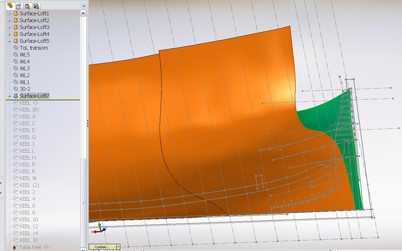
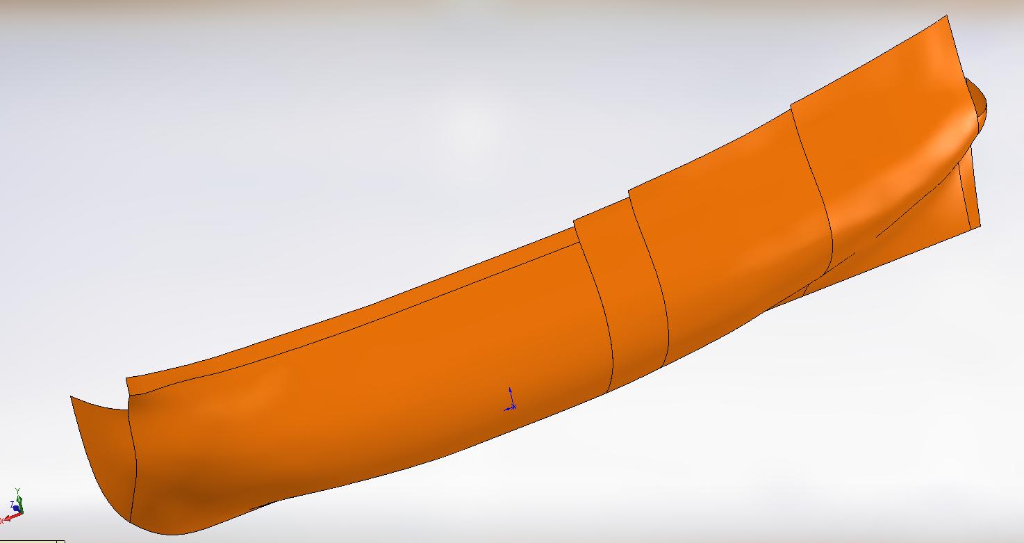
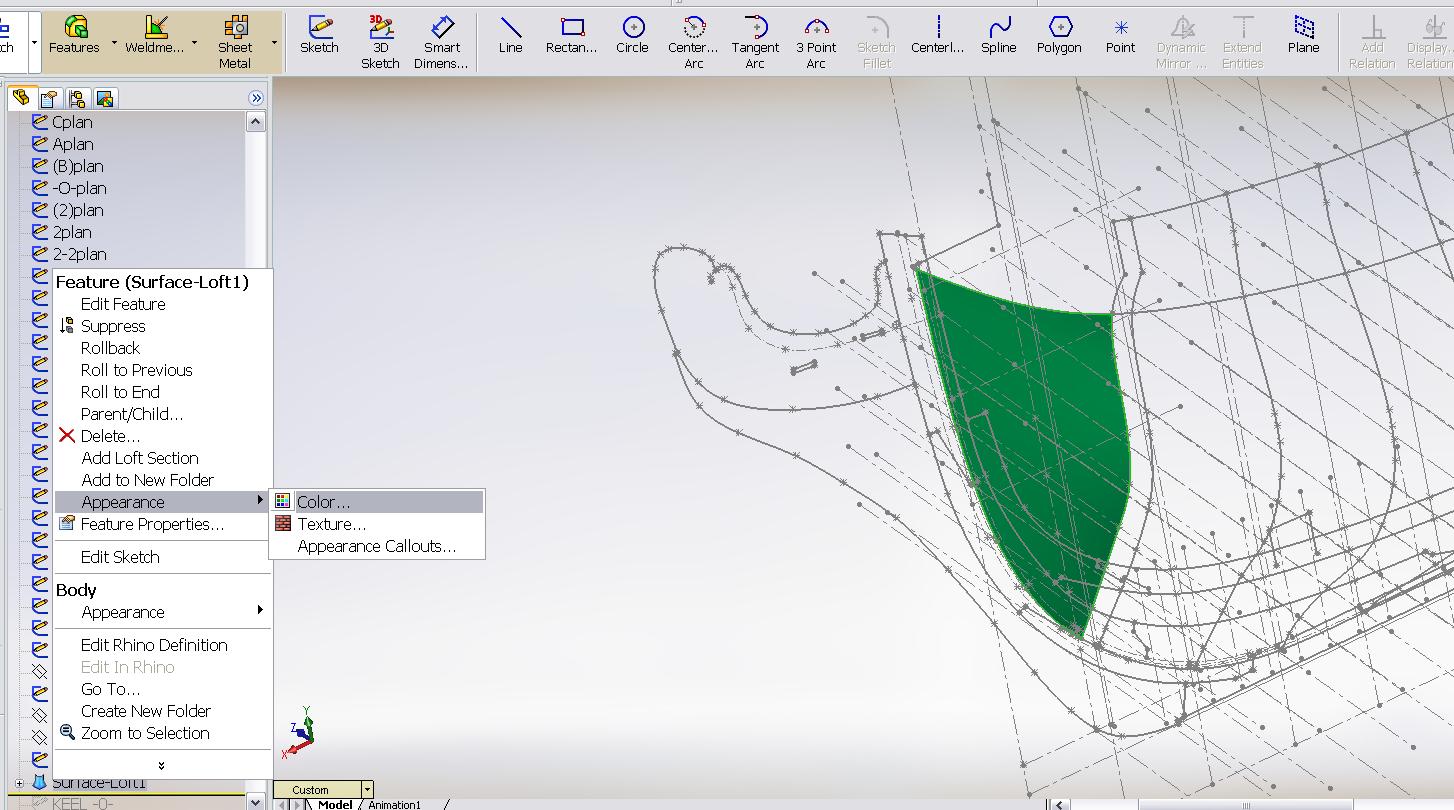
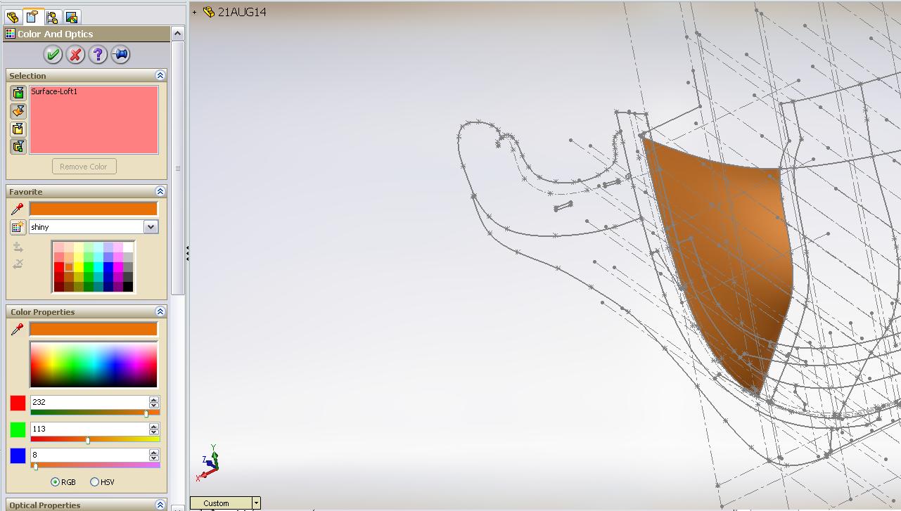
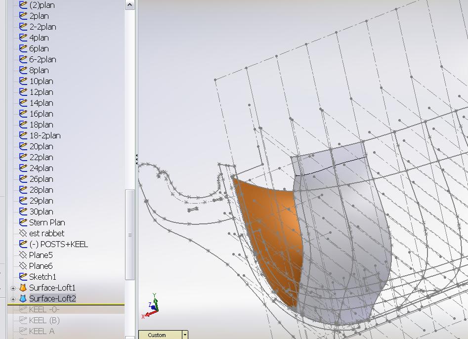
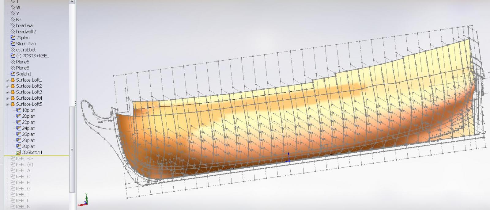
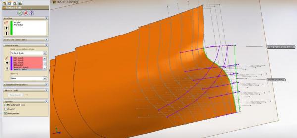
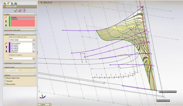
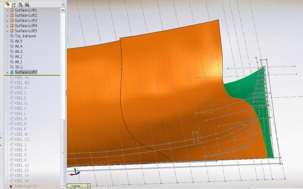
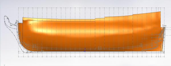
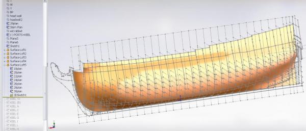
... continued 10. Solidworks completes the lofted feature shell shape. It will default to a GRAY colour that can be changed by picking the “right mouse button” over the area. A menu table pops up. Pick APPEARANCE… 11. Pick COLOR, then pick the colour of your choice. 12. I then begin the process for a new LOFT FEATURE for the second group of stations Picking the GUIDE LINES as describe previously 13. Pick the PROFILE LINES and Solidworks fills in the shape. I have do this is increments of no more than three frames as my poor old computer gets confused with too much math and crashes if I ask too much of it. I then pick the green check mark to accept what the program created, Pick REBUILD and SAVE before I attempt the next group. 14. In the end I once again had the complete hull lofted. I have yet to complete the stern transom shape


-
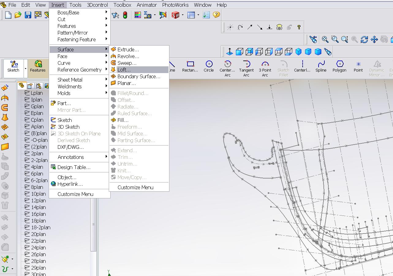
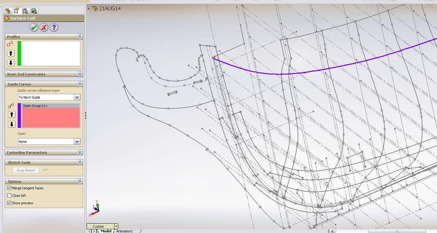
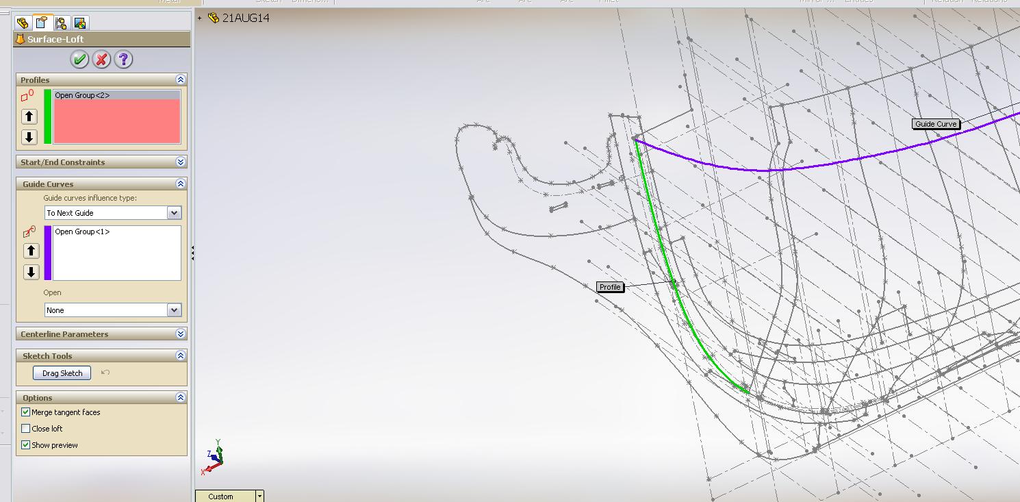
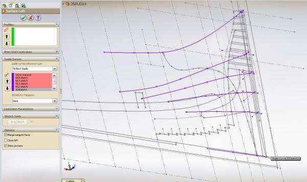
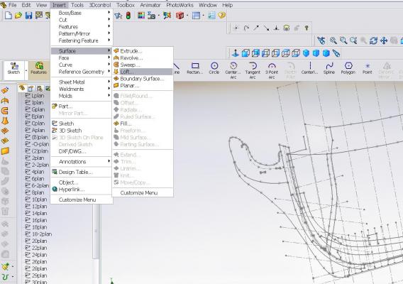
... continued 6. Pick LOFT FEATURE drop down menu – Insert > surface > loft 7. Pick first GUIDE CURVE pick in the lower box to highlight it; pick the guide curve on your drawing; pick the green check box 8. Pick 1st PROFILE LINE (I created a separate line on my RABBET line sketch to represent this) pick the upper box to highlight it; pick the profile line (Upper Rabbet Line on Stem Post) pick the green check box 9. Pick 2nd PROFILE LINE I picked my shorter HEAD Bulkhead frame outline in step 3 above


-
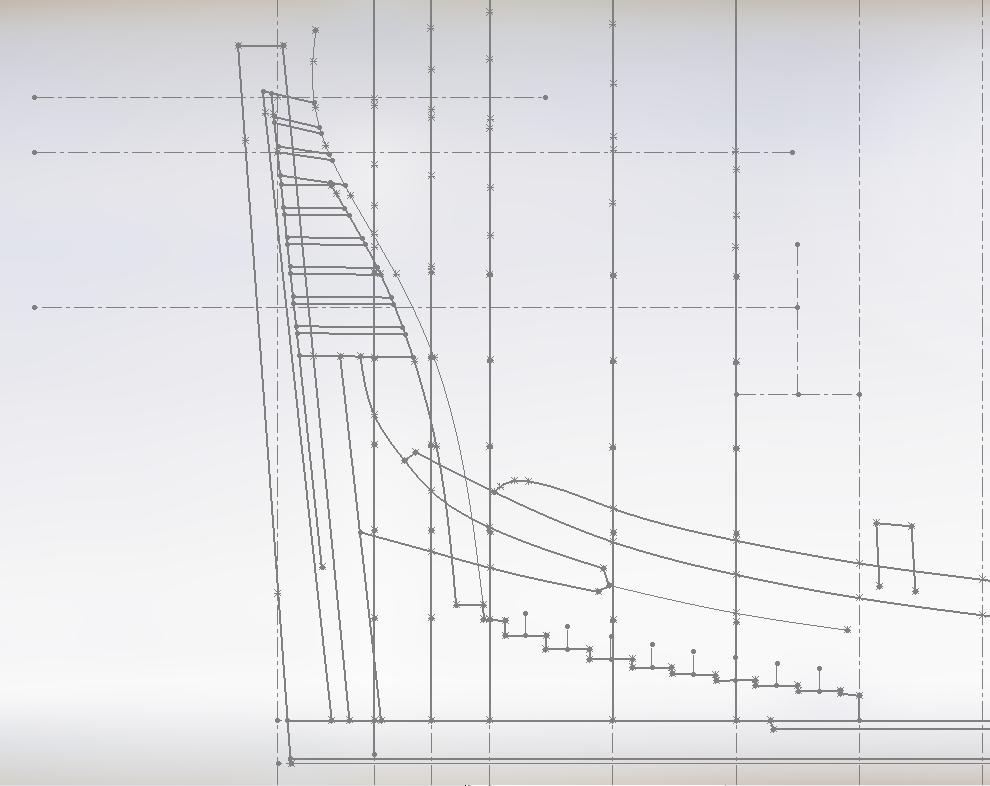
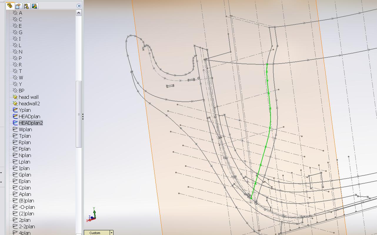
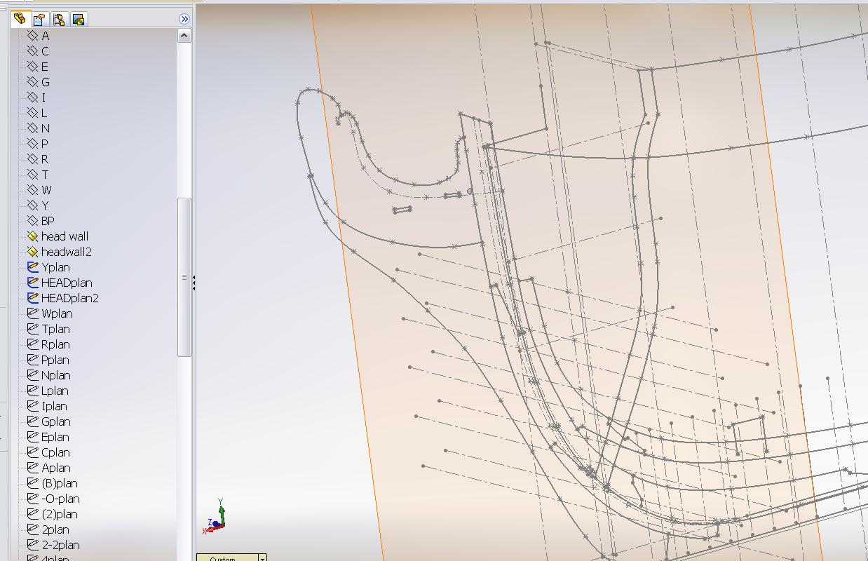
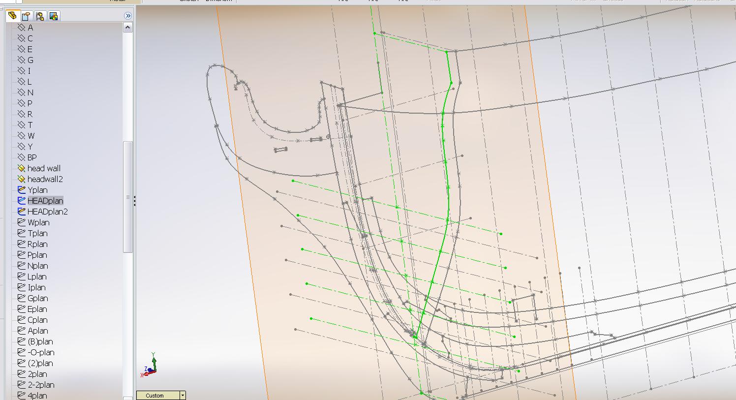
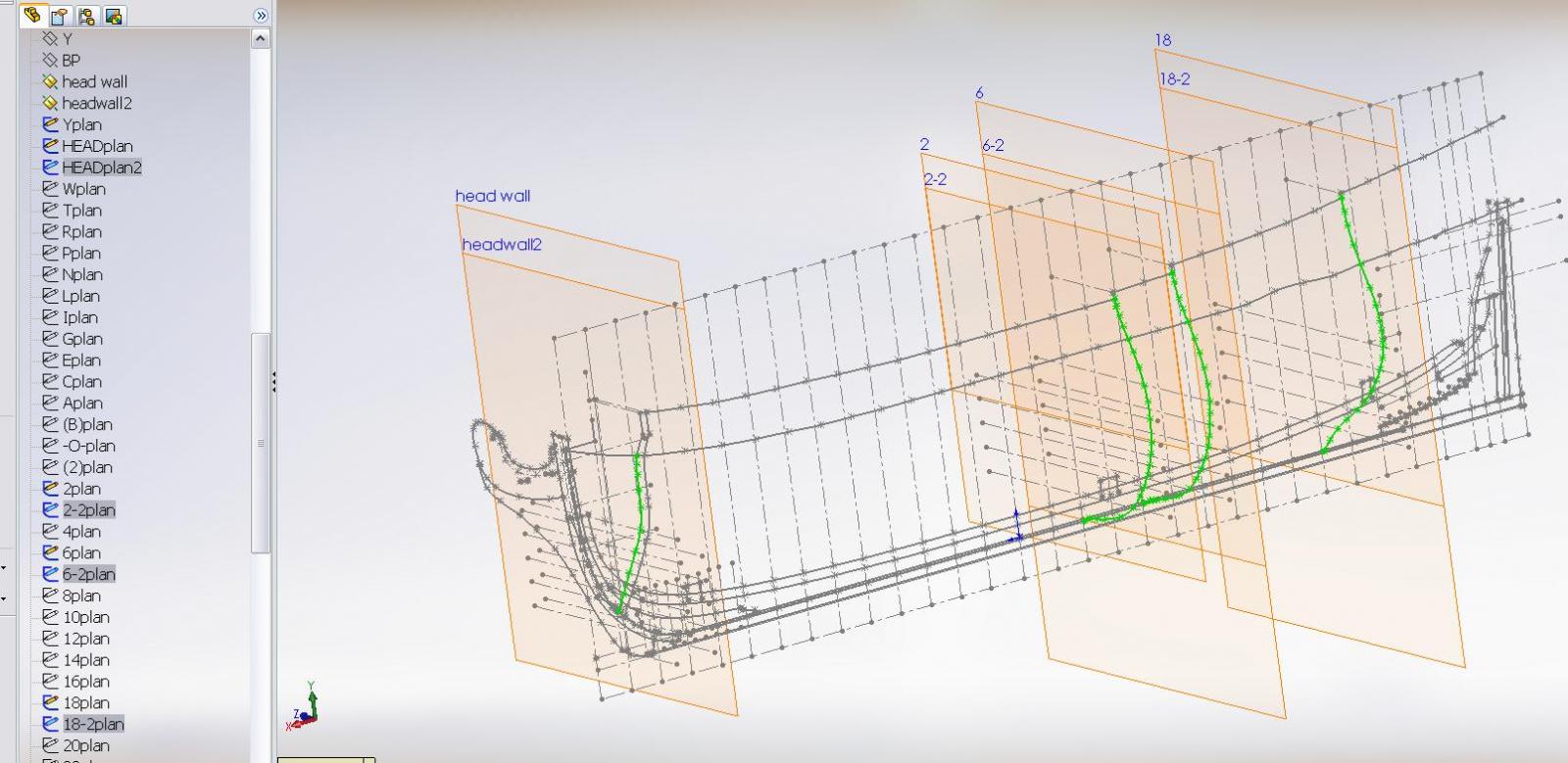
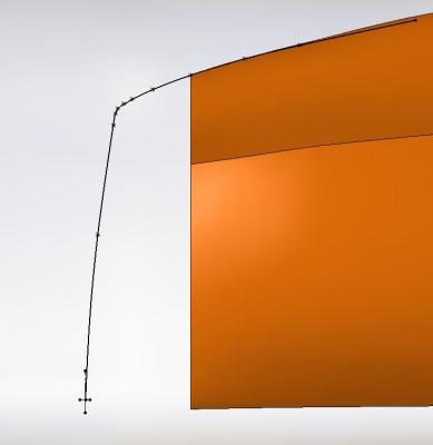
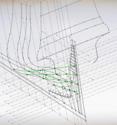
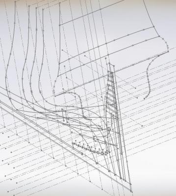
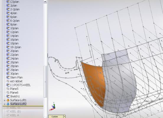
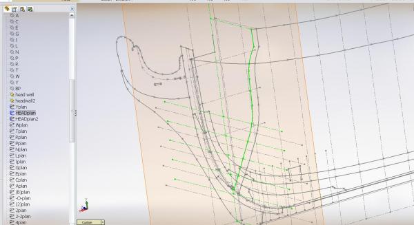
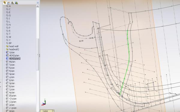
My meager progress report I am sure there is likely easier ways to do what I've done..... Having established the rabbet line I completed the bow shape as follows: 1. You will note I have an additional frame outline towards the bow. The aft is the foremost station Y off the plan. The one forward of it is located at the forward face of the HEAD bulkhead. I created two (2) planes at this exact location. 2. On one I created the full HEAD Bulkead frame tracing. 3. On the other I traced over the first to create the shorter HEAD Bulkhead frame outline. 4. I did this at each station where the TOP TIMBER heights change 5. I created a 3D sketch of GUIDE LINES. I created new lines at the very top of the top timbers where the elevation changes more to follow shortly

-
I confess to not having done this on models but have seen it done elsewhere must be tapered to pull back outwards freely without damaging anything will it work on such a tiny hole... you never know until you try one make sure you allow adequate drying time for the wood putty (commercial sawdust and glue)
-
TFFM: The Fully Framed Model 4 volume set and seems really worth every penny I spent Missteaks? not me
-
it has been awhile since I posted any update. I've been rather busy with diversions. My play area (workroom) extension is well underway with the size having been slightly more than doubled ..... studs up, wiring to electrical plug outlets and light switches installed, drywall up. I need to wire to new lights in the ceiling and install the drop ceiling tiles that I have had stashed in a corner for about 12 years. Then the walls and floor get painted and I move everything back in. Geeze I hope it is big enough! Left work last night to have a beer with an old acquaintance (employment placement agent or better known as a head hunter aka pimp)... why? because I just discover back when he actually worked for a living he was a naval architect. We discussed my model. The first thing he said was that I was going to have trouble because I would be striving for perfection and they were anything but perfect. (damn he knows me and my type well... probably why he is so successful in his new career) He told me they would build per the yards experience using the contract and drawings as a guide. Dimensions would be close to but not less than the scantlings. Most people couldn't read so they did what they knew and made it functional utilizing the sizes and shape of wood available to them. No two ships of the same design would have been identical even if built in the same yard off the same plans with the same contract. There was a lot more discussed but the "striving for perfection" has been a battle I've been losing and to hear him blurt it out so easily having not witnessed my struggles so far.... hit me hard on the chin. So maybe what some honest people here on the forum have been saying will finally sink in and I can relax some? Then I came home to discover my four volume set of TFFM arrived. Started thumbing through volume one and the rest of the evening was lost. Thank you David for writing the 3 volumes... have not yet unseal wrapped Greg's contribution but I am certain it will have me cemented to the chair also! At present, after having completed establishing the rabbet lines I am re-lofting the hull and want to better establish the stern but as I said I've created many diversion projects so it may be awhile.
-
This might work as a fix to at least try on one hole.... 1) make a long tapered rectangular plug (long enough to handle) of the finished size you desire 2) give it a thin coat of releasing agent (vasoline?) 3) insert it into the oversize hole and fill around it with wood putty 4) let it dry for 30 minutes or more 5) pull out the tapered plug and see how it looks carefully file/sand to finish if it works
-
Amazon just sent me an estimated shipping date for the book. They're now saying between Sept. 23 and Oct 3rd This is not the first change in ship date Luckily I have quite a bit to keep me busy until then Possibly I will receive it in time for my birthday in November or maybe for Christmas???
-
Proper light for a modelling table
AON replied to Mike Y's topic in Modeling tools and Workshop Equipment
Mike That lamp (Daylight Black Desk Lamp D33041 with Energy Saving Daylight Tube) seems perfect for the space! coupled with an illuminating magnifier I think you will be quite happy. -
Regarding the Morope unravelling and twisting.... I wonder if it is comprised of strands made of yarns and whether they are wound opposite to each other? This is supposed to keep it from unravelling easily and also possibly tame it somewhat for coiling.
-
Impressive work. That is about the fifth time someone has mentioned TFFM ............... so I just bought the set. Let us hope it brings me some of your luck
-
However long it takes you have got my attention!
-
I will admit that one lay rope being stronger than the other seems like a load of cow dung to me. I have never heard it before and of course anything you discover on the inter-web should be taken with a large dose of salt. I've be looking through my dad's Manual of Seamanship BR67 Vol. 1 1937 page 95 Chapter 3 Cordage Yarns are made of Hemp laid up right handed Strands consist of a number of yarns formed together, the number depending on the size of the rope formed; those intended for right-handed rope are formed left-handed, and vice versa. A Hawser Laid Rope has three strands, and is laid up the opposite way to the strands. They are usually right-handed. The size of rope is measured by its circumference. Hemp can be white or tarred. It is used for running rigging, hemp hawsers and small boat cables. The tarred variety is used when subject to continuous exposure to weather and sea. it then goes on to explain how to determine the strength of rope and does not suggest one lay is stronger than another. If someone has more information on uses for opposite hand rope I'd love to know! I just know my use of both handed steel wire rope on hoists (1975/76) kept the hook centered and laid naturally into the grooves on the drum.
-
found the following at: http://www.animatedknots.com/rope1.php?LogoImage=L..&Website= Z Twist (Right Hand Lay) & S twist (Left Hand Lay) Rope Lay Most three-strand rope has a "Z" twist or a "Right Hand" lay (as the strands progress away from a viewer, they rotate clockwise). What is rarely known is that this is inherited from early recognition that Right Hand laid Hemp was stronger than Left Hand laid Hemp. A Left Hand lay or an "S" twist is normal for steel cables and used to be more commonly found in cotton rope where the Right Hand lay offered no benefit.