AON
-
Posts
2,869 -
Joined
-
Last visited
Content Type
Profiles
Forums
Gallery
Events
Everything posted by AON
-
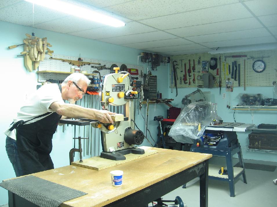
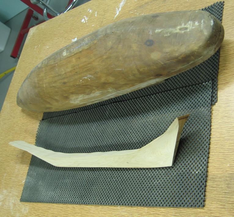
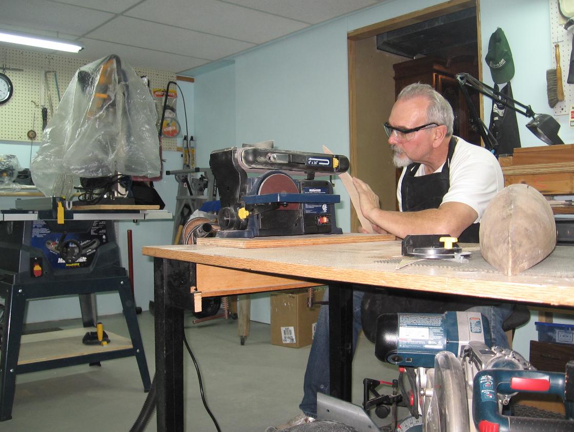
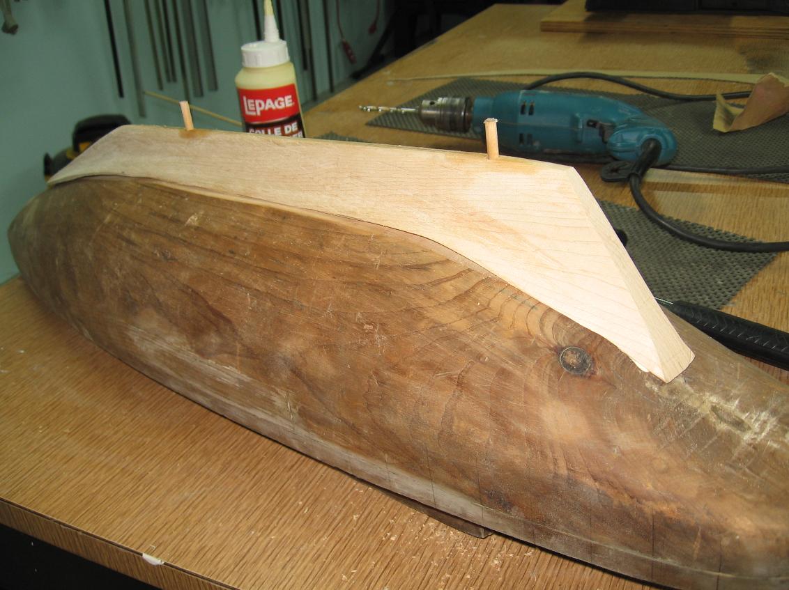
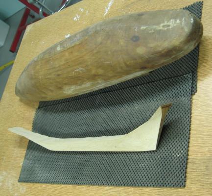
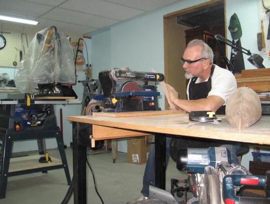
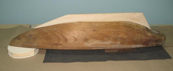
 Monday. 13 October 2014 Ate my fill of the Canadian Thanksgiving Day meal followed by a healthy slice (or two) of pumpkin pie. After having gotten my expanded play room in working order (and learning where I put everything all over again) I must get going on the Charlie refit as Christmas is right around the corner. The good thing is the working associate does not expect it to be a 100% complete and first class job as he suggested eye hooks and … a strange shudder just went through me. Completed the other half of the skeg as far as I dare go with it. I find it is all to easy to chase the other side and then find you’ve gone too far and now you have to re-work the first side to match and…. Tuesday, 14 October 2014 After my darling wife and I took a long morning drive along the Lake Erie shore line to get some photos of the fall colours I went back to Charlie and cut the skeg out of the block with my band saw. Sanded the top side on my belt sander and then sanded a flat onto the underside of the hull to help them both fit up a bit better. I drilled and pinned the skeg to the hull with doweling after having applied a small amount of wood glue to the hull and the holes. I’ll need to fill gaps and blend with wood filler and generous sanding to complete the marriage of the two pieces. My plan now is to complete a simple support cradle as was requested to rest the schooner on and then start on the rudder. I intend to use old copper electrical wire for the gugeons and pintles. These will need to be hammered, filed and formed into shape. Once the rudder is attached I’ll cap the cabin and build a small wheel house and ships wheel. I intend to install stanchions along the deck edge once again using copper electrical wire and silver hobby wire of a much smaller gauge. Then I will install the masts, gaffs and booms. I will have completed my sail making course by then and will decide whether to add sails to hide the lack of full rigging as I may certainly have run out of time by then. Wednesday, 15 October 2014 I will have to run out today for wood filler as my small tub has dried up. Does anyone know the secret of keeping the tub from drying out? I thought of storing the tub upside down (like paint) but as it is not liquid I cannot see this working Possibly I should by tubes rather than a tub as with a tube I can squeeze out the air and then put the cap on.
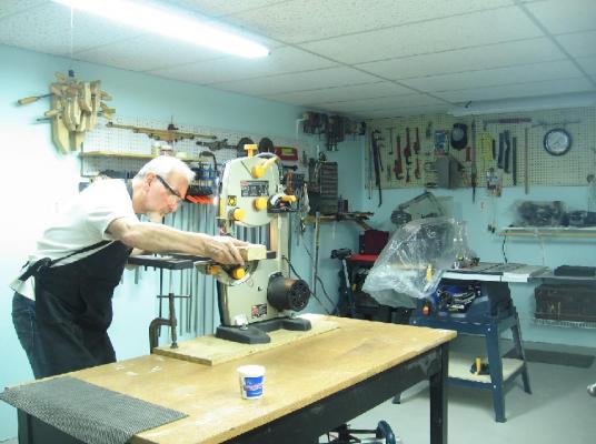

-
somehow there is always more time in the winter months!
- 969 replies
-
- 1
-

-
- hahn
- oliver cromwell
- (and 1 more)
-
Sorry for the delayed response I've been busy reassembling my rebuilt/extended workroom and it is just now in a useable state. Also been making phone calls all over the banana belt looking for Silkspan for the sail making seminar I signed up for being held next month in Niagara on the Lake (or NOTL as we type it up here). I had to drive over the river on the weekend into Niagara Falls New York and go to Abe's Hobby Shop to get any.... he has a good supply. Getting across the border was a real treat... 30 minutes in line RE: re-re-re-fairing.... every bleeding time I start looking at it I see something that might be better if tweaked just a wee bit more ... so because I am a slave to this new obsession of mine I will be at this for some time. It has got to pay off down the road... right?!? Don - I still cannot manage to fillet (add a corner radius) to the lofted feature. I'd love to know how you manage it. Alan
-
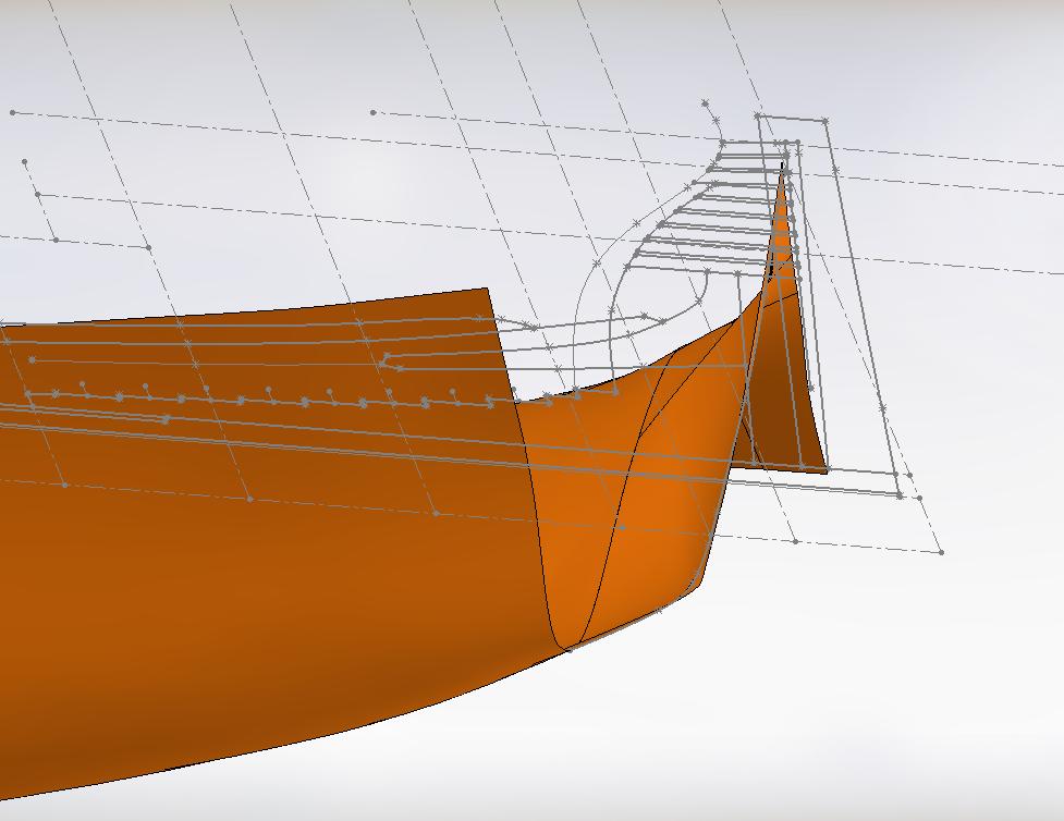
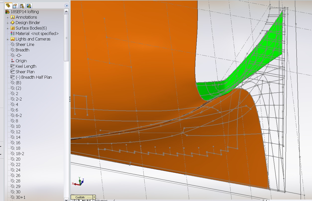
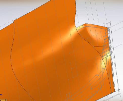
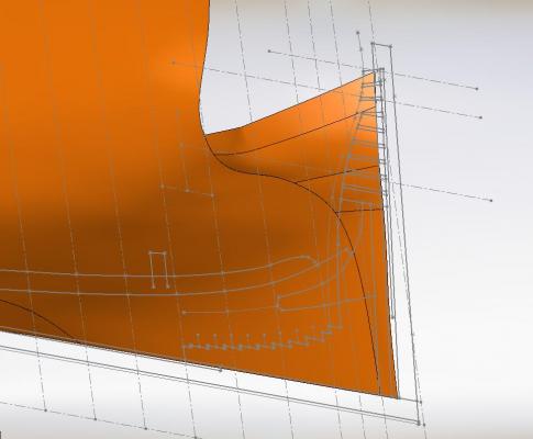
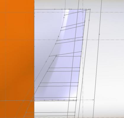
Spent some time away attempting to put my work room back into order and while engaged in that I had another thought about this extended corner issue on the lower wing transom. I have always attempted the lofting of the stern hull from the top down, doing the upper wing transom with the corner first. The computer completes the calculation for this first and blends it into everything else afterwards. I wondered what might happen if I reversed it; did it from the bottom (keel) up. Then the computer would not calculate the corner until the very end and it might not blend the same way eliminating the extended corner. I tried this and it seems to have made a difference. I am happy with the results and so I am considering this task completed. On to the next! PS: You will note the short vertical guideline I added in the "top level last" image. This line is a curve (adjusted by eye) and eliminates the undercut I was experiencing in the corner.


-
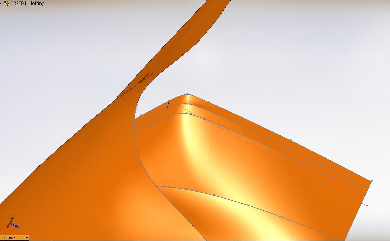
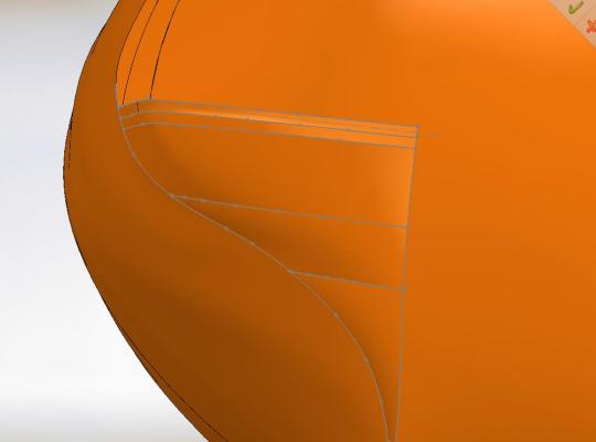
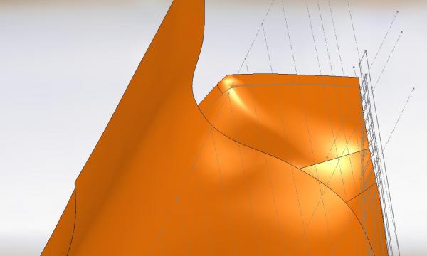
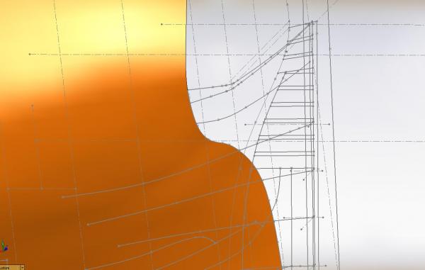
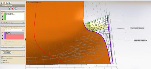
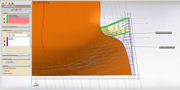
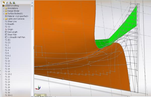
Regarding the shaping of the upper wing transom: I have been working on the final shape of the top side of the upper wing transom and the blending into the hull... checked with sections at various elevations.... and I believe I am getting quite close to the proper shape. It seems to match the plan more closely and looks to me like the images I see in Ree's Plates and approaching the likeness of the photos that have been posted. I inserted a guide curve 1 foot below which represents the underside of the upper wing transom timber. It took some time but I've almost got it blended properly. The corner between these elevations has a wee bit of an undercut to it. I can see it as I spin the model slowly around. If I knew how to 1) make a movie with this program (which it can easily do) and 2) post an avi attachment, you could see it too! You can see it a bit in the third image in the shadow of the reflected light on the shape. We have a new kid (less than half my age) starting at work on Monday and if I am lucky he just might be able to teach me! I need to insert a few additional guide curves below the underside of the upper wing transom to eliminate the corner seen below the 1 foot elevation guideline.... so try to ignore the fact that remnants of the corner are still there. Please critique the images below and let me know if, in your opinion, I need to clean my glasses and possibly book an appointment for an eye alignment.


-
Mike Not certain why I was avoiding "Oliver Cromwell" but curiosity got to me. Am I glad I visited. I'll be back! Alan
- 969 replies
-
- 1
-
-
- hahn
- oliver cromwell
- (and 1 more)
-
Then I did my lofting in batches. The wing transom has the corner at the top and the round just below it I admit the shape is not right, the profile of the hull is incorrect, BUT I GOT IT! I should mention I had to draw a shorter lofting guideline line on new planes that were directly over top of the established waterlines The loft feature recognizes the shorter line to create the shape. The longer waterlines confuse it. When I section the loft horizontally I can see the shape is wrong. I will have to redo it all properly

-
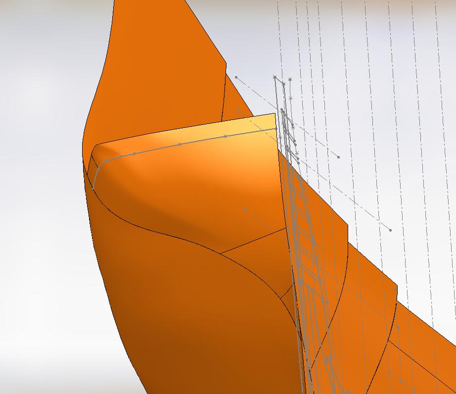
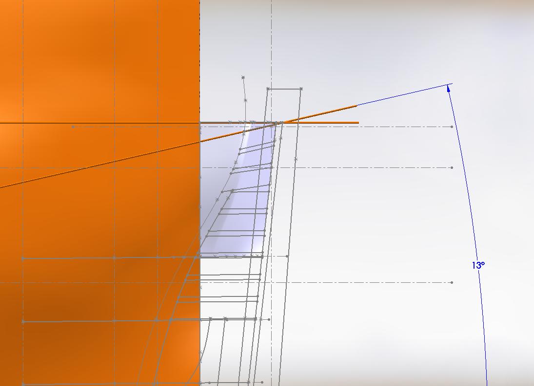
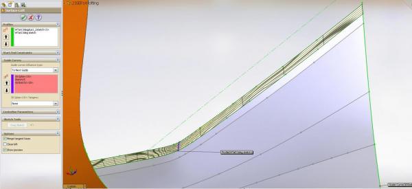
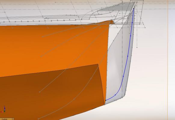
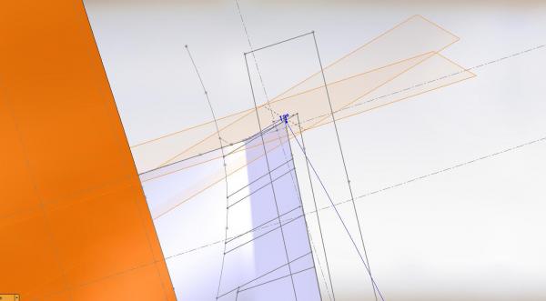
Then I sketched the outline of the outer top side of the wing transom on the angled plane Then inserted another plane offset from the angled plane and sketched the rounded corner outline to it. You will see I still had the bad "extended corner" loft feature turned on to see it When I was doing my sketch on the offset plane it created a shadow effect below the angled plane (where it cut through the loft feature) and I added my line along the shadow.
-
First I managed to get the angled plane.... I might add it was simple First I created a horizontal plane at exactly the point the wing transom upper outer corner intersects with the keel on the sheer plane Then I inserted an AXIS at this point on the new plane... This is my pivot point Second I picked INSERT > REFERENCE GEOMETRY > PLANE I picked that I wanted it inserted at an angle and typed in the angle of the slope of the wing transom I picked the new horizontal plane and then I picked my pivot point (the axis line) and it inserted the plane on the opposite side I wanted I picked reverse and there it was

-
I think I've got it!!! Will post later today Have to get ready to go out and get the paint for my workroom Hope to be moving everything back in to it next weekend
-
It is 6:07 am The sun has yet to grace the horizon to reveal the glorious crack of dawn I had a fantastic sleep and awoke with an idea A simple idea I might add If this works all I can say is "isn't that they way it always turns out when things seem impossible?" Wish me luck as I may not be beaten yet
-
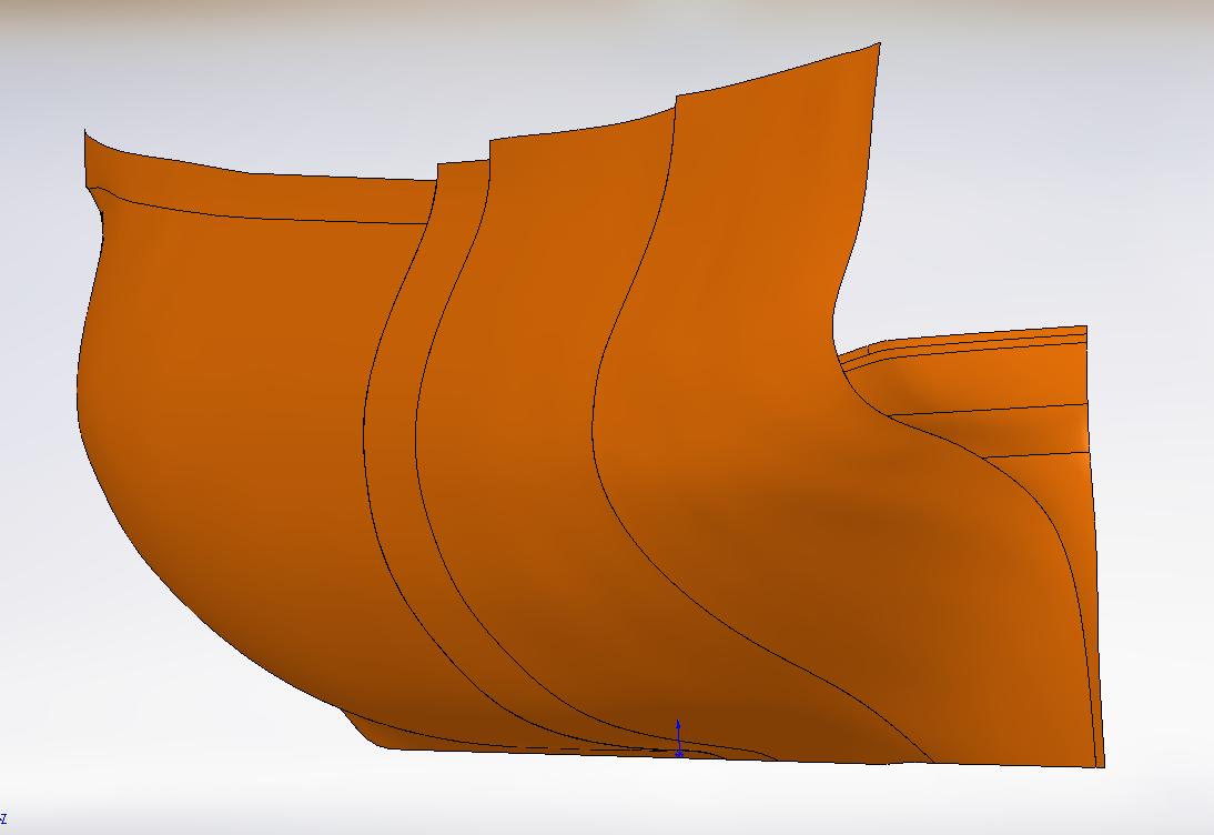
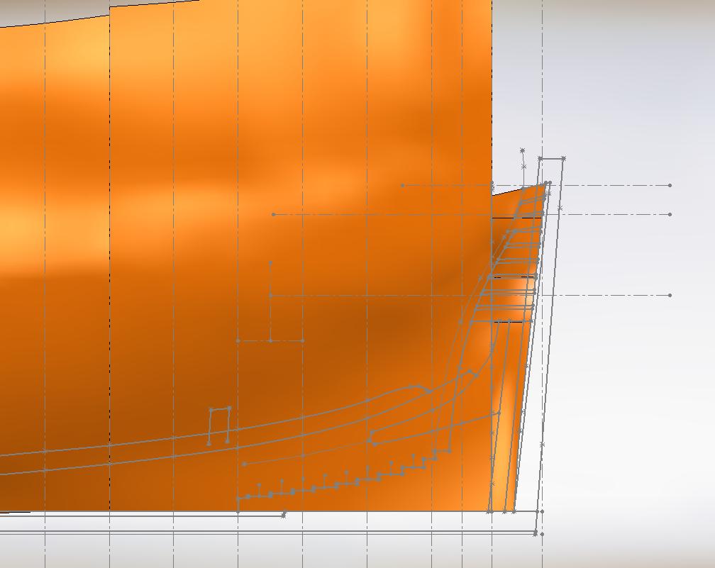
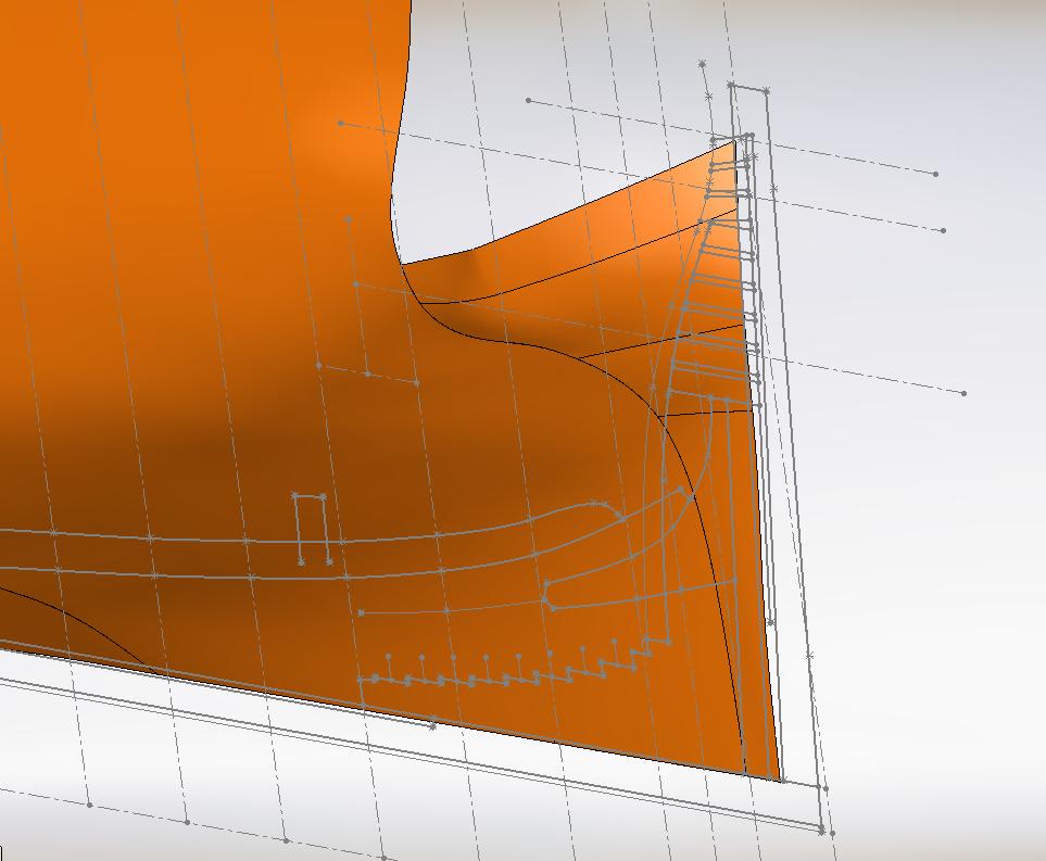
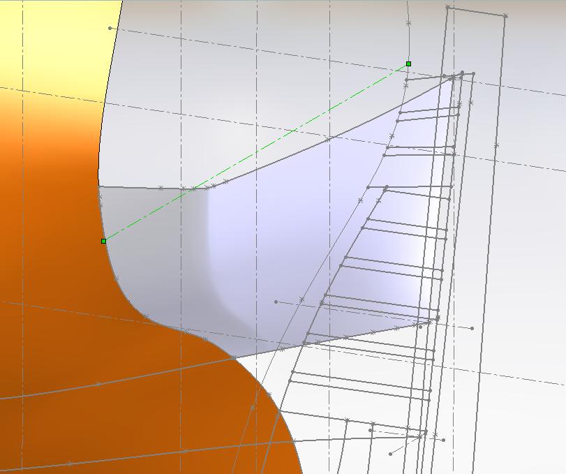
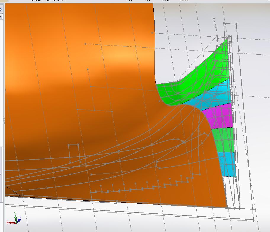
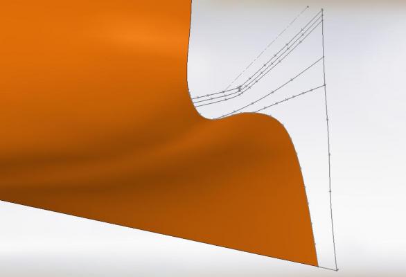
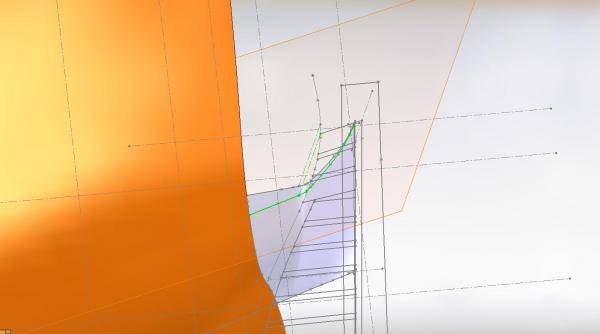
Once again I apologize for airing my frustration with completing this shaping challenge of the wing transom. I am worried I may have put some good people off. I said I'd post warts and all and today's there were some warts. If my Solidworks skills were at all better I would have nailed this ages ago. I reference the excellent photo of the Bellona build at the following link (go to entry #272) to see the shape I strive to achieve http://modelshipworld.com/index.php/topic/196-hms-bellona-by-sjsoane-scale-164-1760-english-74-gun-as-designed/page-19 In my two photos below (one is in profile the other in isometric) I have just deleted (in a copy of the model) all the guidelines Using the waterlines and the sketch I made of the wing transom shape I get an extended corner that I just cannot seem to get rid of. The green line in the isometric view depicts the intersection of the wing transom with the frame at that elevation. Of course it will actually be lower as can be seen in the slope of the wing transom timber sketched on the stern post the back ground. This line helps me visualize where I am at that point. Hex nut mentions a "variable round once the surfaces are stitched together". I confess I do not understand what is meant by the latter part but the variable round is a feature applied to solids and the loft feature is not a solid. At least I cannot get it to work just as I cannot trim or extrude cut a lofted feature. At this point I feel I have two options: 1) continue my struggle for a few more days 2) accept that I haven't the skill level to get the proper shape in the lofted feature and when I have made it a solid to cut the frames I can then reshape the wing transom with fillets and extruded cuts and then there is plan B: take a rasp/file/sanding stick to the wood and reshape it when I get to that stage of modelling. Sorry again if I transferred any of my pain to any of you. Members here are a God send and I'd be nowhere without your helpful comments and encouragement. Regarding my "corner" problem ... for now I will sleep on it.

-
Don, Sorry (I apologize but we Canadians are famous for apologizing when not necessary) but this is exactly what I did on the 29 Aug and was told it was incorrect. It was simple to do and since then I've been trying to imitate something that now I think I am being told I should not (????) Either I'm just thick in the head or I'm mighty thick in the head. I don't get it. It has been a trying day on all fronts ... and I am supposed to be working so I have got to go. Going to have to take some time to clear my head, and re-read it all to understand what I am not getting. I am however glad it makes sense to someone. :^) Don't youse guys go anywhere 'cause I have a strong inkling I'll be a need'n all the help I can get. Alan
-
Thank you for the comments and guidance Druxey and Don I will definitely take another look at my "corner" issue. Don, the answer is both Yes and No. I do not think the wing transom shape is quite correct... look at where I have a corner problem... you have no "corner". Take a look at the photo Druxey posted on the former page. There is a definite "shaping" of the wing transom that I guess I haven't quite gotten correct as yet I can see it on the Bellona build also. BTW... I hate that you could produce the shape so (seemingly) easy. Tell me it wasn't that easy (even if you have to lie to me)
-
Had a moment before breakfast so I gave it a go and all lofted easily except the last bit left undone which gave me grief As there are no timbers in this area from which this loft would be used for the templates I am considering leaving well enough alone and attacking the stern top half
-
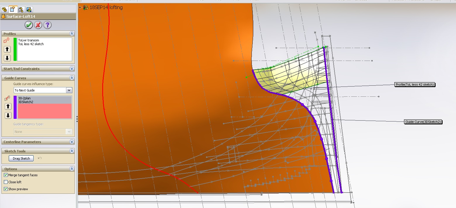
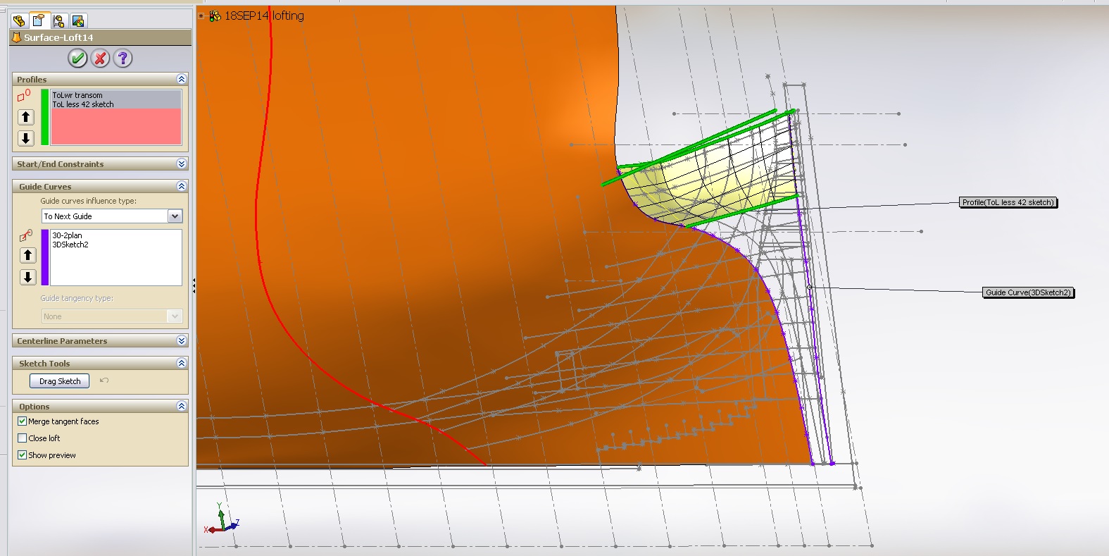
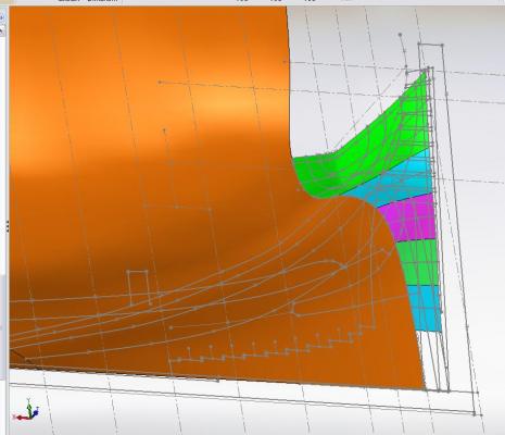
I have been trying to get the lofting of the stern done and had continuously "failed" (between that and my computer crashing) I sketched in a grid work of guide lines to improve the shape I sliced and dice it I broke it up into wee pieces in an attempt to get portions of it to work Finally last night I had an epiphany I turned it all sideways in my mind used the horizontal lines to be the profile lines versus the guide lines Used the vertical lines to be the guide lines versus the profile lines The damn thing finally seemed to work on the upper wing transom area or at least about 80% as it did not follow all the curves I had but the shape is seemingly more proper in that there are no waves, folds or creases. I will continue on this path a wee bit at a time until she hopefully fills in
-
Finished Chapter 3 What have I learnt? She was faster than any other ship in the fleet due to the skill of her crew and likely the skill of her builders (?) Possibly some anomaly akin to the first Bluenose Seems breaking yards and top gallant masts was a common occurrence as every other week a ship had to turn in for repairs Starting Chapter 4 The Glorious First of June This book is a keeper for me
-
Sorry guys! I have been away more then here the last little bit. I have been reading the book, having gotten through a good quarter of it, a description of the build (I will be inserting loose sheets about the builder having gone bankrupt and his notice of death), painting scheme, what life was like for a seaman of the time, and now reading about her time at sea in the early years when she was just launched. I am thoroughly enjoying the book but only have time to read four or five pages a night ... just before lights out ... in the hopes I might enjoy it even more in my dreams. The type is large enough, I suppose that would be to get the requisite number of sheaves in it to qualify as a book? As I am getting "more experienced" in aging I will not complain about the font size.
-
Received my book on Friday! What perfect timing as I had just finished reading the book I was on (about the Great Deportation of the Acadians) two days prior
-
Having read and re-read both messages, I've slept on it yet again and am leaning towards attempting to continue with the lofting feature for now although switching to a solid feature might be easier ... something to work out over the weekend. In either case I find this part is quite challenging
-
FORGIVE MY ANCIENTNESS Are you suggesting I not use the loft feature but rather complete the aft portion as a solid which will allow me to extrude shapes and "trim" away to get what I need? Holy old bald headed saint dulibon... I think that would do it!
-
Thank you Hexnut. Your sketch along with Don's helps quite a bit... but I'll still need time to digest it all and formulate my plan of attack Divide and conquer, eh?!? (Did my Canadian just slip out?) I was just starting to attempt my idea and it made more sense early this morning Having a wee bit of difficulty executing it. Alan
-
Thank you Don I'll have to chew on this for awhile to figure out "how". Working with a thin loft feature does not seem to allow me to "trim" or "extrude cut". I think my last idea has some merit particularly when I join the thought with what you've described above. Wish me luck! Alan
-
Having slept on it last night I tried something new early this morning.... shorter guidelines that start/end at the two profile lines. This failed also. Then I had another idea while having my morning shower... I've always found that I "cracked the code" to many design conundrums during my morning shower.. this might be a strange way to resolve a problem but it usually works for me. I will try my new idea tonight if I have the time. The idea is to create a multitude of new horizontal planes beginning just below the top side of the wing transom and then drawing new guide lines of the sliced profile at these decreasing elevations... adding these to the loft feature and hopefully the result will be what is wanted. I may need to remove the original guide lines after the new sketches are complete if the loft should fail with them. Once again, if someone has another idea please let me know.... and thank you for following.