
DONATION DRIVE - SUPPORT MSW - DO YOUR PART TO KEEP THIS GREAT FORUM GOING!
×


roach101761
-
Posts
204 -
Joined
-
Last visited
Content Type
Profiles
Forums
Gallery
Events
Everything posted by roach101761
-
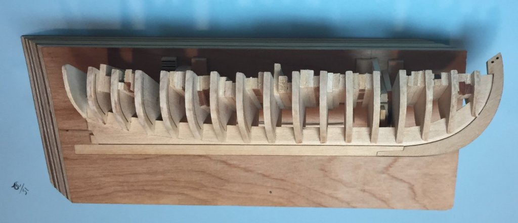
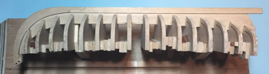
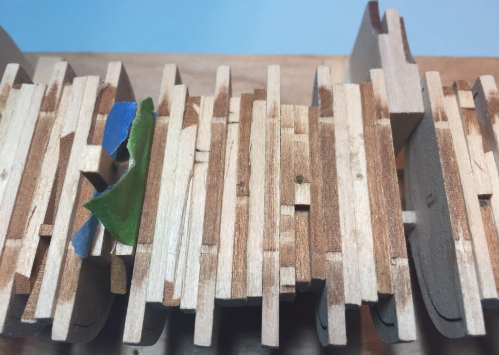
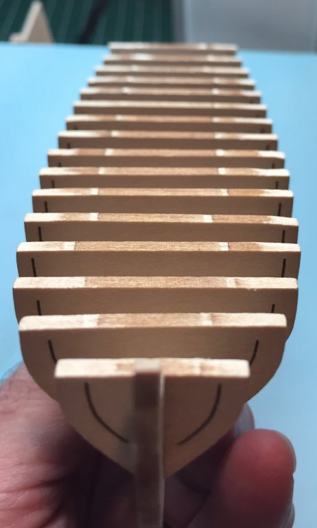
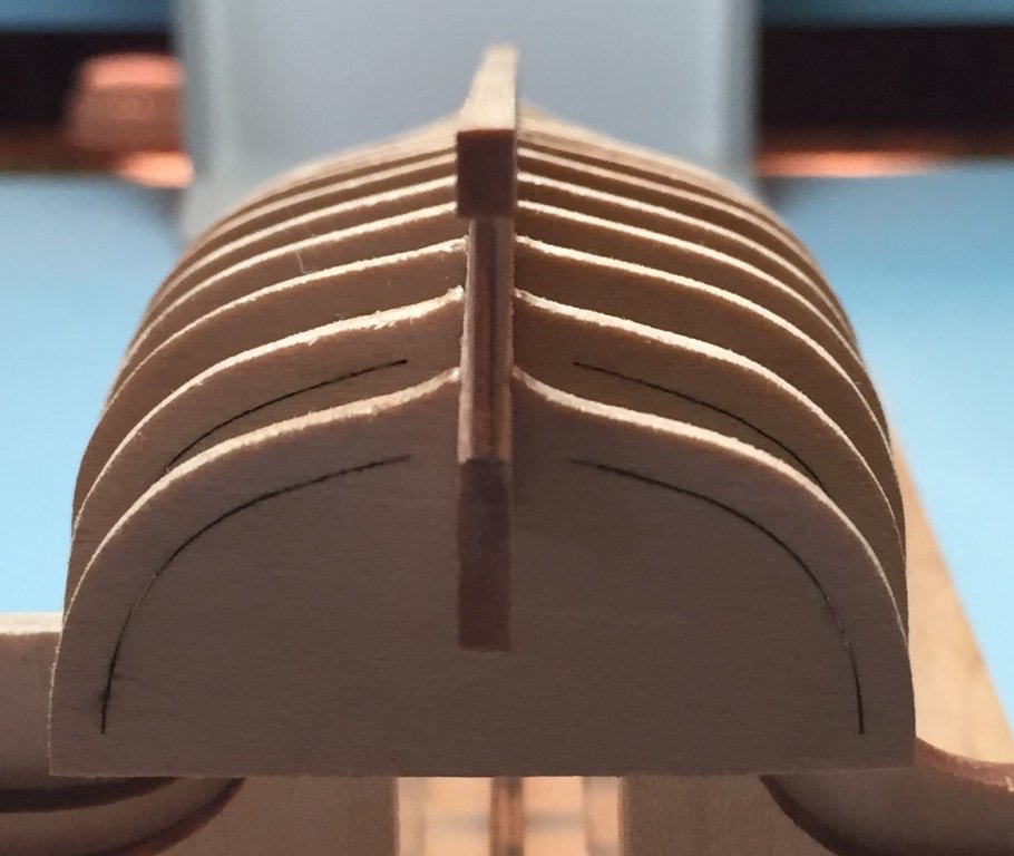
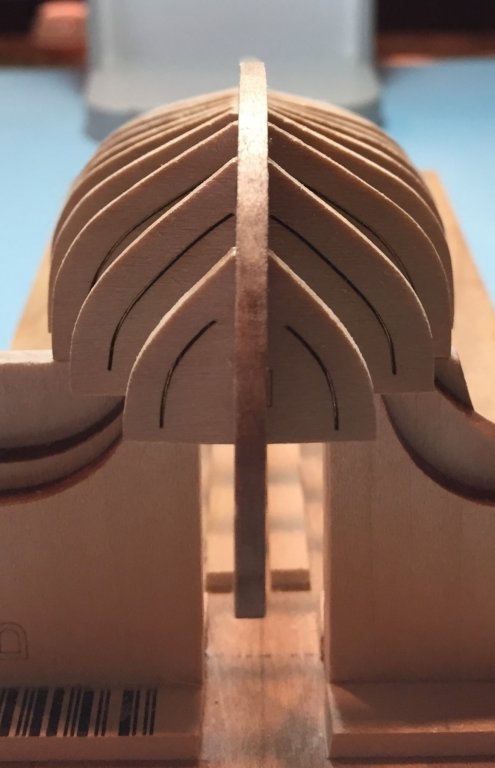
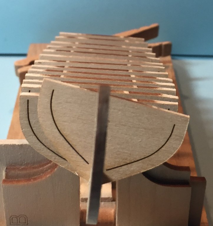
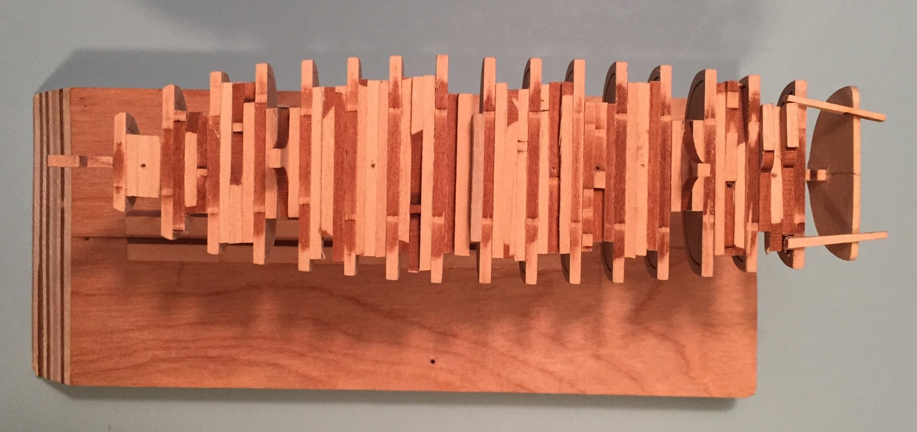
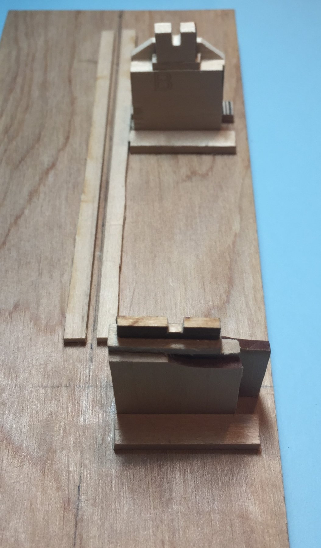
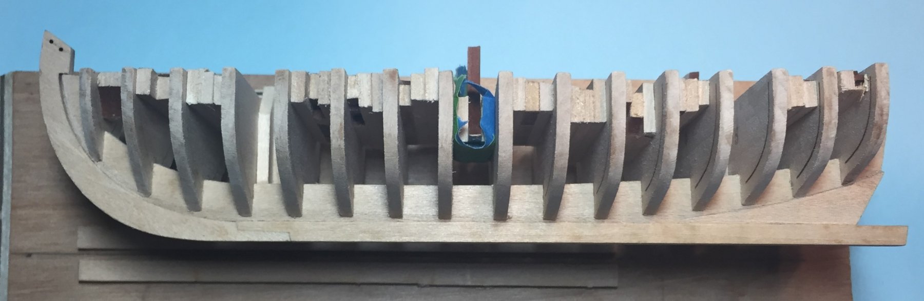
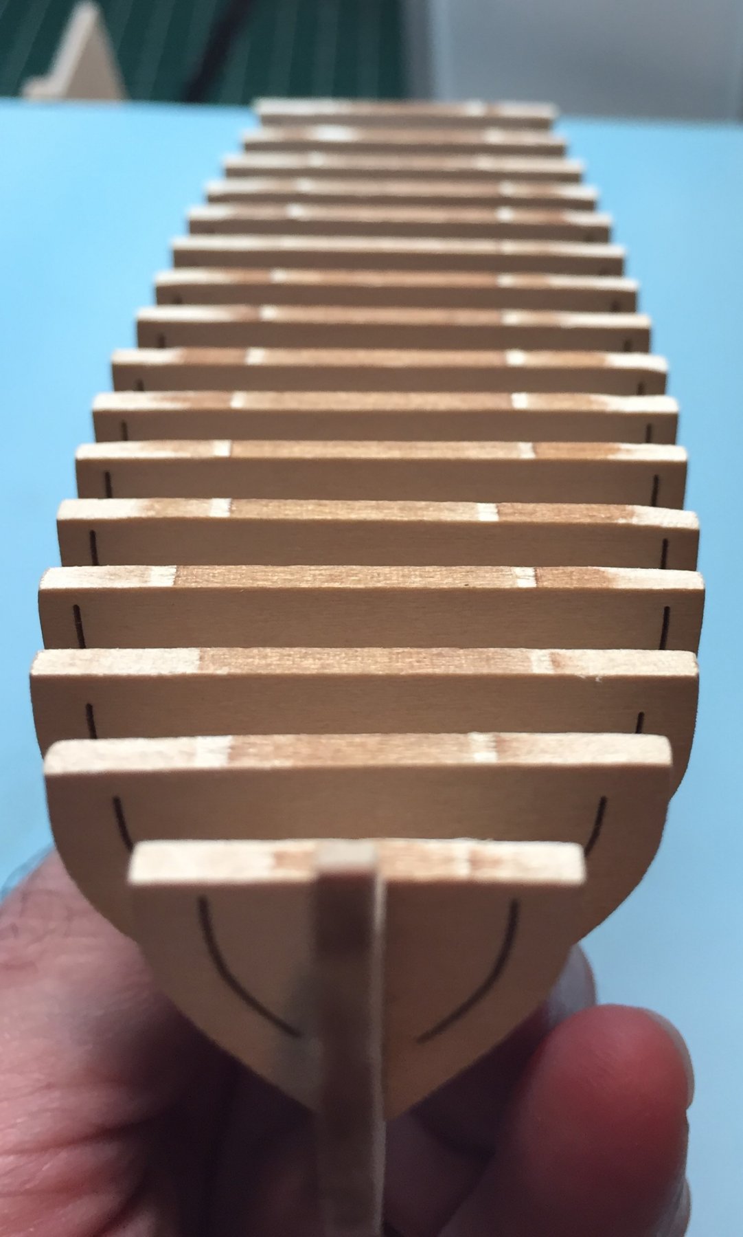
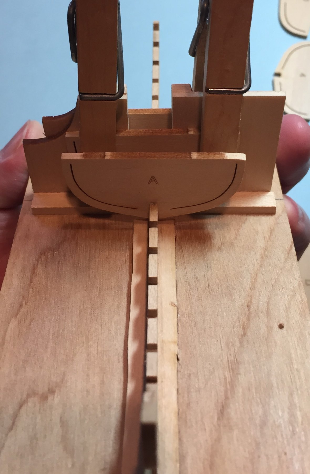
FAIRING THE HULL--CONT. I have made some progress in fairing the hull and through it I decided that I would place the last two remaining blocks in the hull that I had left open for mounting it on the building board. I found that for the majority of all fairing processes it was easier to hold this small boat in my hands while I worked it with files. I believe most here and the designer during the prototype build found this to be most convenient. As I mentioned above I decided to attach the transom about midway during the fairing process. I was concerned that I needed it there to establish the correct bevel on the one or two frames forward of the transom. I also braced the transom with two small strips of wood. What a big difference this made! This post and the following photo's are a little out of sequence because I have not yet written about the actual fairing process. That is a harder writing task. BLOCKING UP THE HULL AS I DID, and placing the last two blocks has made a big difference in eliminating the twisting action of the hull. There is ZERO MOVEMENT! It is like working with a solid piece of wood. QUESTION FOR THE GROUP. I am curious if using the strip method others have used also resulted in zero movement? The above the photo and the one below are the two views of the model with all the stabilizing blocks glued in. I was rewarded with zero movement in the frame. I have left them higher than the others because I plan on removing them earlier than the others so I can remount the boat on the building boarding during the planking process. Most likely after the 4 upper planks have been installed. The photo below is the braced transom. What a difference. NEXT I will discuss installing the transom. This will be before I report on the fairing processes for the boat.

-
Years ago Model Shipways and Model Expo released a kit of the Chesapeake sailing log canoe. I did not buy one. Had no interest then. I now have an interest in this kit. Did anyone buy one and put it up on the shelf? If so, would you like to sell it to me.
- 1 reply
-
- 1
-

-
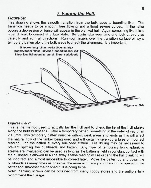
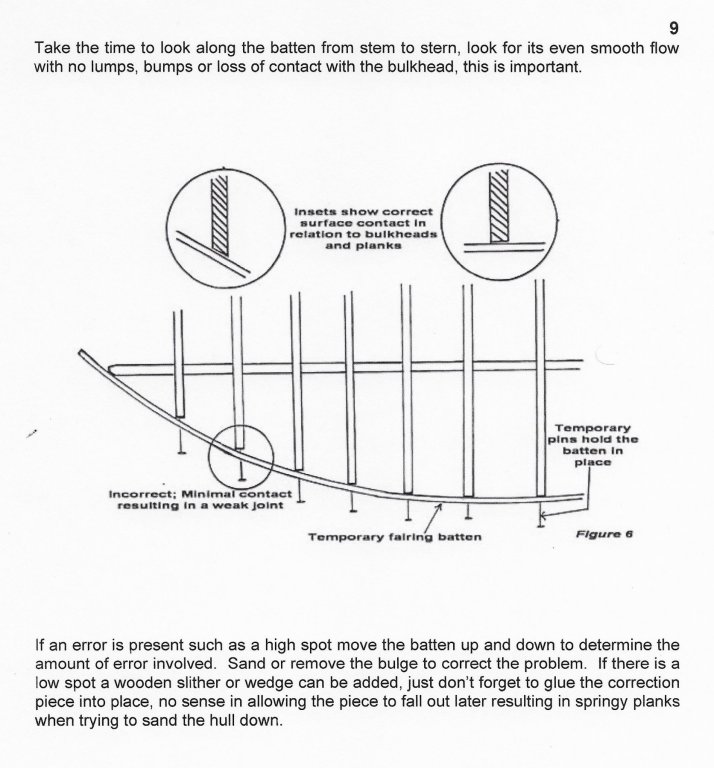
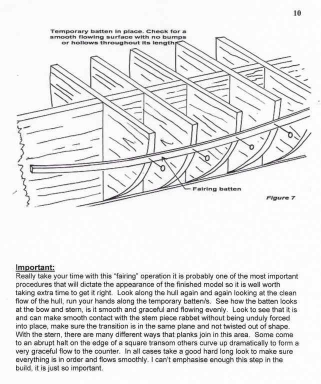
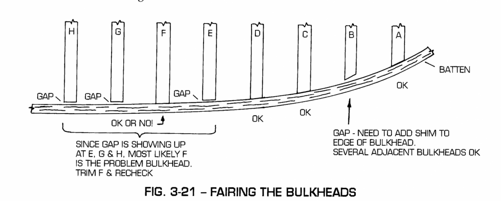
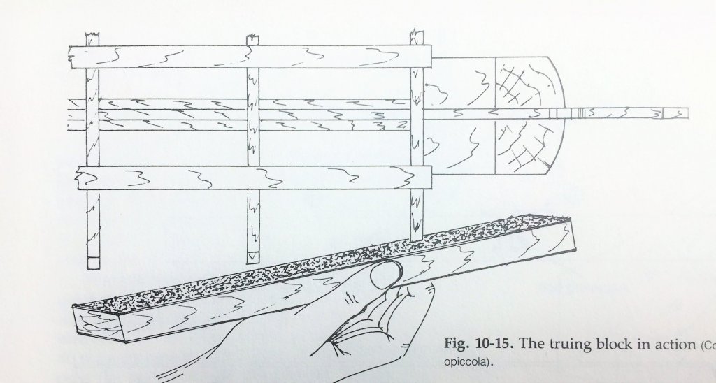
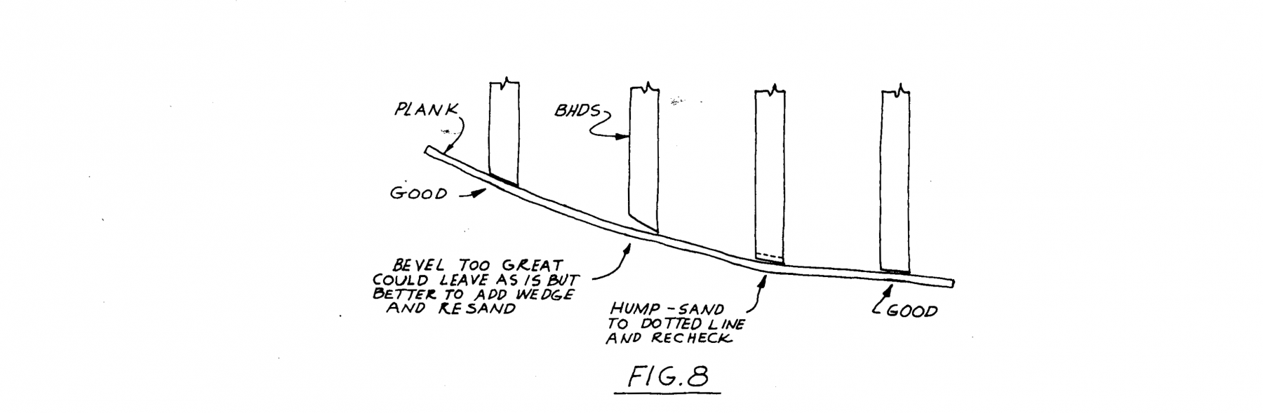
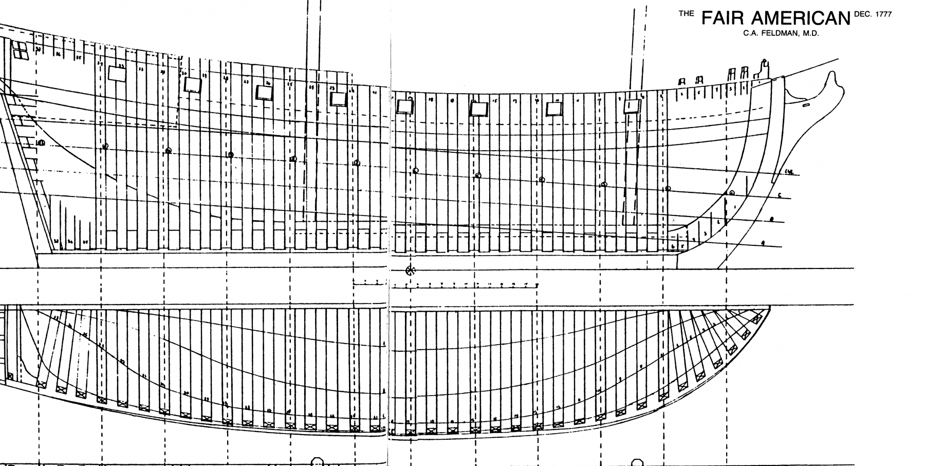
Fairing the Hull--cont. A few quotes and diagrams from my books that define and demonstrate the issues surrounding the fairing of the hull. Fair. 1. To adjust to a gradual, constant, smooth curve or line, eliminating all irregularities, kinks, bumps, humps, or other inconsistencies to the line of the curve. 2. Smooth, or sweet, as in a fair run of planking. Jim Roberts, "Planking the Built-Up Ship Model", C. 1987, Model Shipways Inc. Hereinafter Roberts. For Fairing "...Sanding blocks of varying sizes to reach the different shaped areas of the hull surface are the best all around tool for this task. The only general requirement for them is that they should be long enough to span at least two and preferably as many as four frames or bulkheads. " Roberts. "Select a piece of scrap wood long enough to straddle three frames and wide enough to supply a surface for sandpaper. I call this a Truing Block. (FIG. 10-15). ed. attached below. Wrap medium to coarse sandpaper (40 to 60 grit) around the block. .... Stroke the frames in one direction, sighting the truing block to see that it makes contact with at least three frames on each stroke. Use a plank to test the surface for vital contact. If the plank lies flat on the surface, you have accomplished your purpose....The canted surfaces, at the bow and stern where the plank curves to form the structure of the hull, must accept the plank on a flat surface. Remove some of the the edge of the bulkhead. ...Flatten and true the surface with the truing block. Keep the surface contact of three bulkheads when possible, two at the sharper angles." Milton Roth, "Ship Modeling from Stem to Stern", C.1988, Tab Books Inc. Hereinafter Roth. The above are some of the most detailed descriptions of the fairing process that I was able to find in my home library. The following images are from various of my books that demonstrate the fairing issues and process. From Ben Lankford in How to Build First-Rate Ship Models From Kits. Model Expo c. 2002 From Eric Ronnberg Jr. with revisions by Ben Lankford, Fair Amercian instruction Manual, Model Shipways C.1988 From Clayton Feldman, 18th Century War Brig Fair American, C. 1986 Phoenix Publications. From Roth. The most detailed instruction on how to fair a hull was found on the NRG web site under articles database. You can easily locate it by selecting the tab above that directs you to the data base on the NRG Web Site. The title page and chapter 7 on fairing is copied and pasted here.


-
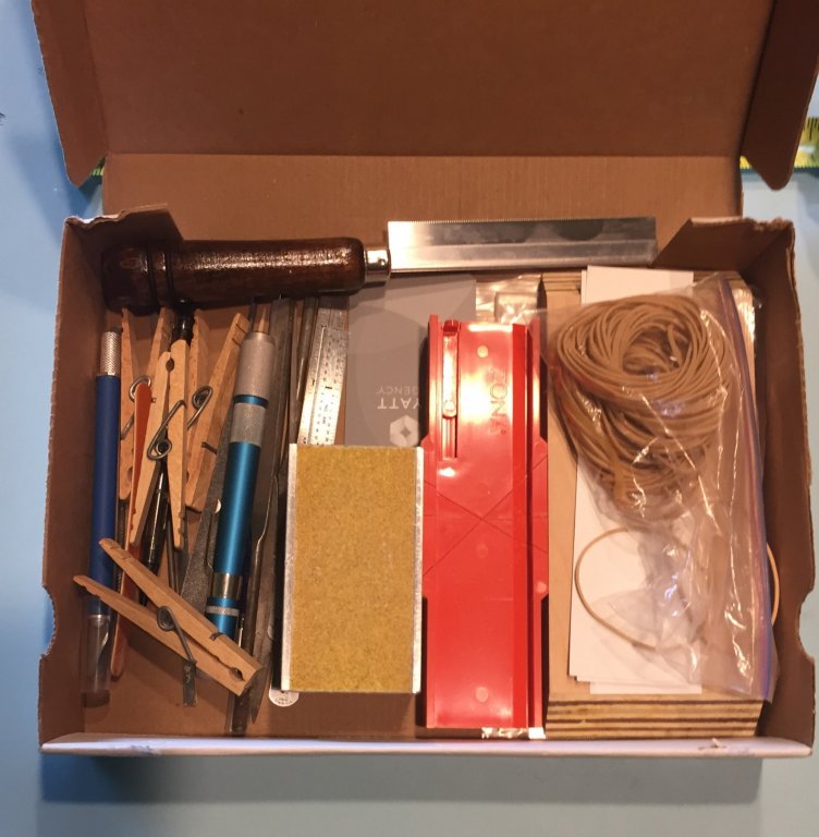
My responses to the above. Steve--Thank you for your continued interest in my little project. I will brace the transom. I thought about making blocks with all those angles,(much too hard) but instead will place two strips on top of the transom and connect them to the last bulkhead. I will see if it stabilizes it enough to fair the transom to receive the planks. John--Thank you for your new interest in my project. The object of the log is first and foremost a teaching opportunity. If you (or anyone watching)catch me making assumptions about the skill set of the reader please let me know. Of course the draw back is that it may end up being the build log with the highest word count ever! Which in itself will put people off in reading it. For those who do not know, I am a lawyer, so high word counts is what I do best. Even slightly better than over thinking everything. Eric--You are right and thank you for your continued interest. The method you chose to square up the frame is great and you got a great result. Thanks for posting the links to your photo's in you build log and placing them here. That was especially useful. It was an added bonus that it also contained the link to Chucks prototype. It was also a great reminder to mark the location of the sheer plank on the bulkheads. I am reserving comment on the "daunting" building board for later. Tools are great. But remember that I am trying to limit my use of tools so a beginner will not have to buy too much. Many may be reluctant to buy tools to build a model that is routinely offered for sale for less that $50.00. In fact, I am playing a little game with the tools I have used or will use. They all fit in a small box. See the photos below. Jack--Thanks for your interest. My work space is small also. In fact I am building the model at the bar in my kitchen. I live in SW Florida. It is hot all the time and my garage has two cars, bikes, recycling bins, garden tools and all that other stuff. My power tools are in the garage, but for the most part all my building efforts are in my kitchen. The bar is 18 inches wide and the work space is essentially the green cutting mat you see in the photos. Of course I spread out down the bar and place the tools, plans and the box the model came in further down the bar. Most days, I pick it up every night and put it away. My tool box thus far. I put the protractor away because I do not anticipate using it again. The wood block is just an extra one I had that matches the building board. I also do not keep the scalpels in this box for safety reasons I put them back where I keep them. They will fit though.
-
FAIRING THE HULL This seems to be an area where model kit instructions and authors of ship modeling books consistently fail the beginner. There are two problems. First. I have found that beginners I meet with sailing experience and a boating background readily understand the concept. I have found that many beginners with no boating experience do not readily grasp the concept and the process and the result to be achieved. I was one of those. My mentors kept advising me that I had not completed the fairing process. My problem was that I did not, or would not, or in my case I could not accept that some of the bulkheads (those in the bow and some in the stern) would require some very pronounced angles/bevels. It seemed counter-intuitive to remove all that wood after I so carefully put in the bulkhead and braced and stabilized the frame. This conceptual problem is further compounded by kit instructions and modeling books that instruct the modeler to "...now fair the hull". Too many kit instructions and too many modeling books make the assumption that all of the readers understand what fairing the hull means. Second. Too little attention is provided in most modeling books to the actual process of fairing the hull and the methods and tools to be used. A typical instruction would read something like, "make sure your file, rasp, sanding block is long enough to span at least three bulkheads and fair the hull." Another issue is that every hull offer's its own unique challenges. One size does not fit all. Therefore, although some of the fairing processes for this model are readily transferable to other models, my focus is on this model of the the long boat. Advantages this Long Boat model offers the beginner in fairing the hull. 1. It is very small. Although my critics cite this as a reason this is not a beginners boat, it is an advantage here. It is a much smaller job and I believe errors will more readily show and are more easily correctable in this small model. The smallness I believe makes it less prone to errors. 2. It is a fully framed model. The distances between bulkheads are only 9/32nds of an inch. This makes it less likely for errors to creep in. I am speaking specifically of humps and depressions here. 3. The bulkheads are made from Basswood, not plywood; cheap, thin, thick or otherwise. This makes it easier to shape and fair the boat. Disadvantages 1. The transom is going to cause some issues.
-
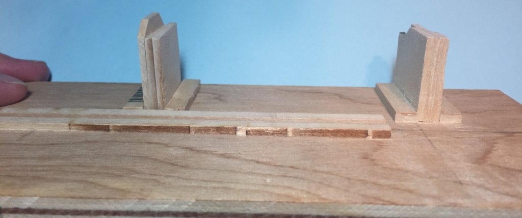
I edited the above to show the finished building board. I actually cut the the gantry walls to allow a wider space to support the model's false keel. It was too close. The model also was not fixed on the re positioned walls because the keel was not locked in. Here is the board with the boat mounted on it before further modifications. I then built up the two fixtures to accept the false keel to lock the boat in place. The false keel support in the foreground is not quite level, but it does lock the boat in place. Edit--6/15/18--The reason it is not level is the result of my sawing off the top by hand and then sanding it by hand with my sanding block. Its hard to make things straight and true by hand sanding. KEY FACTOR---The support pieces can not be the same size where I placed them because the false keel in the stern rises from the floors. To level the boat you must adjust the height fore and aft depending on which direction you have placed the boat in the brackets. I anticipate that I will be able to mark the waterline very accurately later in the build with my building board. I also think that marking the bulkheads for the sheer plank will be easy as well. When the boat is on this stand it is locked in place and very rigid. Here is the boat shown in a variety of positions in the bracket on the building board. NOW IN THE OPPOSITE DIRECTION. It fits both ways on the building board. I will be able to work either side of the boat in any position. You will note the two uninstalled spacers. They are made to fit where the brackets are. I am still fairing the hull and still find the building board useful although in some spots it is easier to hold the model in my hands.


-
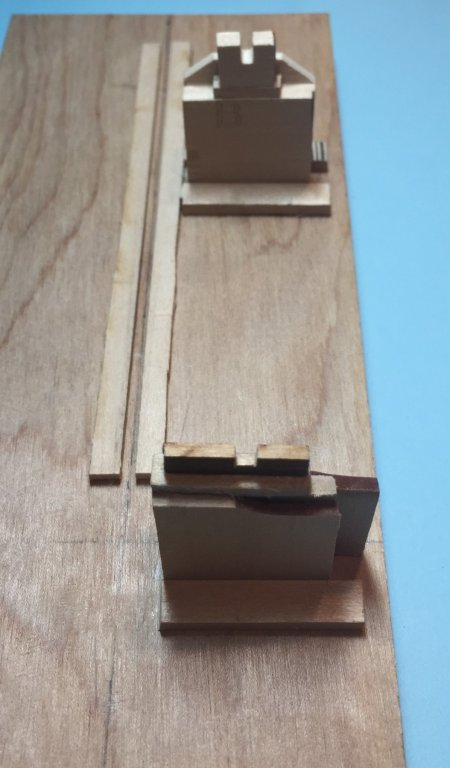
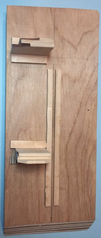
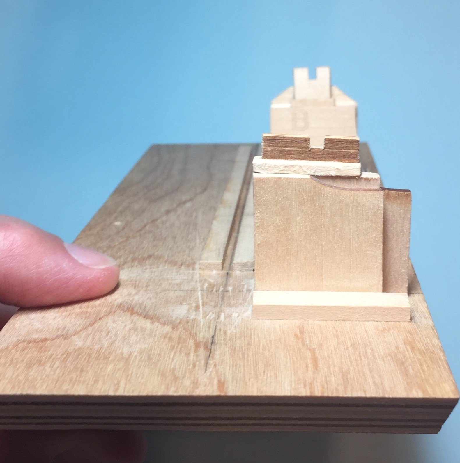
RECONFIGURED BUILDING BOARD to hold model while fairing and planking. I get to say it again. White glue is great!! I decided to reconfigure the building board to hold the model while fairing the hull and planking. To do this it was necessary to remove one portion of the gantry wall and relocate it parallel to the remaining half further along the building board. For kicks and giggles I decided to test the bond that the half I was removing had with the building board. I applied a lot of pressure with my fingers and hands. Far more than the model will ever experience. The bond did not come apart, and the wall did not break off the building board. To break the bond I tilted the board away from the portion of the gantry wall that would remain and flooded the joints on four sides and on top of the support pieces with alcohol, applied with a small paint brush. THEN I SHOULD HAVE WAITED. But I did not. You should wait a while to let the alcohol do its job properly. It will take two or more applications of alcohol to dissolve the bond. The supports and the base of the wall will get saturated. I was able to pry off one of the support pieces fairly quickly with my scalpel blade, and here the wood was less strong than the bond. Some wood was left on the board. This exposed the bottom joint, more alcohol was applied. I waited a bit and the wall came off very easily. I then cleaned the board and the removed parts of all glue residue. Some rubbed off, some I scraped with a #11 blade and some I sanded off. I previously selected the spaces between bulkheads D and E and 4 and 5 as the locations to support the model on the building board. That is why these two spaces were not blocked up for support. Because my model did not have those exact 9/32nds between bulkheads as shown on the plans, it was necessary to sand down both parts of the gantry wall so that each would fit well into the selected spaces. I used my sanding block for this. For the portion remaining on the board I supported the wall on the edge of my work bench and sanded vigorously. The bond did not move and did not even hint at failing. To locate the position of the new support for the model, I simply inserted the piece in the reserved space, turned the model upside down and inserted the hull onto the part remaining on the board. I was able to adjust the alignment and mark the location on the building board with my sharp pencil. Edit to add photos. The two photo's below show the newly reconfigured building board to hold the model during fairing and planking.
-
A reply to a couple of the comments above. Eric--You are correct about the use of proper terminology. Despite my issues with sheer, I am striving to use and spell the nautical terms correctly. We should always make an effort to use the correct terms. If you see additional errors please let me know. I did some edits tonight and may have not caught all the Shears to correct to Sheer. For a while I had issues with Bulkhead Zero (0) before I began calling it the center line bulkhead. I believe it to be the center line bulkhead rather than the zero bulkhead. Let me know if I am correct on this. As to the spacer project----it looks complex, but what it really was, was time consuming. Please remember that I am trying to use minimum tools(not just minimum tools but tools readily available to a beginner), therefore I will not use my table saw or disc sander or drill press. I am also trying to use minimal additional materials. The scrap wood in the kit lends itself to this blocking project very well. I elected blocking the model up because it is an accepted modeling process and I believed it would give me a very rigid hull to work with when I faired the hull. It has done that, it is very rigid and does not twist and flex. This may make it easier for the beginner. I do not know if the strips glued along the top would make it as rigid as I have never used that method before and thus can not compare the two. Above, Toni seems to indicate that they would not. Mark--You have never meet me, but all my local ship modeling friends would agree with you that I tend to over think things. I laughed when I read your comment. Putting aside the criticism of my choice of subject, the purpose of this build log is to try and teach a beginner to build the boat. The instructions in the kit do not offer the detail of model construction that I am attempting here. I have learned over the years that beginners really like to see it, no matter how basic. It makes for greater understanding. I assume nothing about the skill set of my reader, so I explain the mundane. I also am thinking though the process in each step so as to figure how to best explain it to someone who knows nothing about building a ship model. Also, this kit has been done countless times on MSW and my log is an attempt to contribute on some level that has not been done before on this kit or on others. It is first and foremost a teaching effort. If I was just going to build the boat, I would just refer to Bob F.'s build log for guidance and no one here would know I was building the boat. Building boards are necessary to precision. I also believe they will help a beginner. My steel blocks would have been nice to use, but a beginner would not buy them. Thus the flush and perpendicular stationary gantry wall idea. I have re-structured the building board to hold the model for planking. Still do not know how it will work out, but we will see. After all, I get to edit the build log at any point and change my mind later. Additionally, the NRG board has received some feed back that board members are not visible enough on MSW and we should make an effort to participate more. This was my choice for greater participation. I have found that because I must make time to write my build log and check up on comments, I am on MSW more and I tend to participate more often in other areas of the site.
-
That is really a small space that the glue takes up. For my issue the past two weeks the vast majority of the issue(99.9996) must rest with wood. As for my Florida Humidity, this model is being built inside my house were it is a constant 74 degrees with correspondingly low humidity. I live in Southwest Florida. I like my indoor weather. For outside weather I do not invite it in. I go outside for that.
-
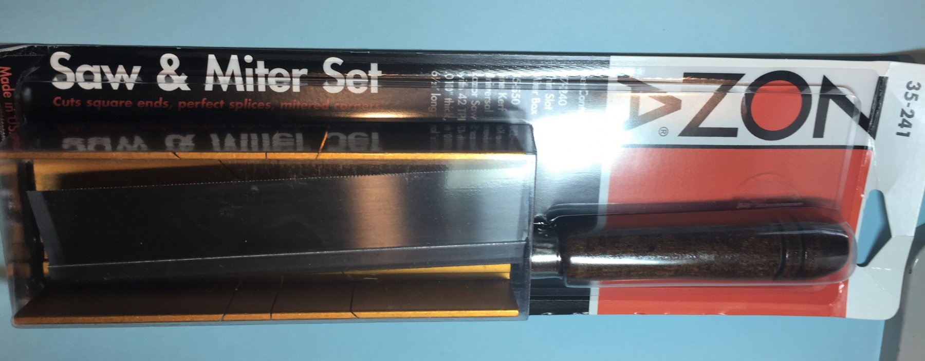
Miter boxes----What is the best one.
roach101761 replied to roach101761's topic in Modeling tools and Workshop Equipment
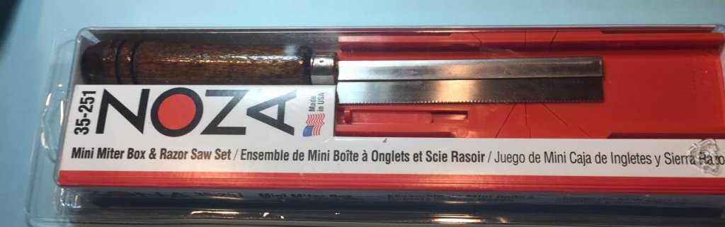
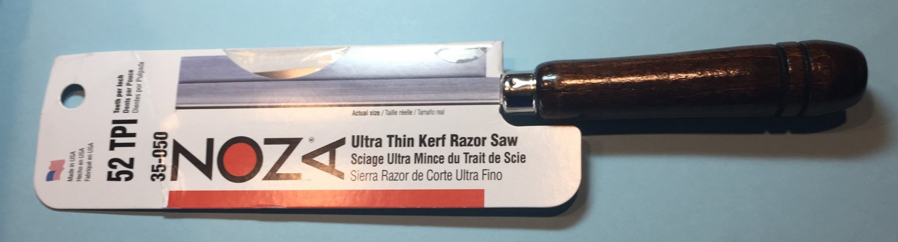
I received my new Zona miter boxes and saws last week. Thought everyone would like to see how they are currently packaged. Metal box and 42 tpi saw. Plastic mini box and 32tpi saw My new 52tpi saw. I wore out my previous one.

-
Steve Why did you pick the long boat as your first model? And I see you followed up one small boat with another small model of a small boat.
-
While building the 18th century long boat I was putting three pieces together that were 3/32nds wide. When done they were more than 9/32nds wide. I concluded that the majority of the problem was that the wood was not uniform and some portions along the 3/32nds sheet were wider than the others and that the two sheets of 3/32nds were not consistent with each other. However, it got me to wondering how much space the white glue I was using was taking up. After all, 1/64th of an inch in ship modeling can look like a mile sometimes. Does anyone have any thoughts?
-
Miter boxes----What is the best one.
roach101761 replied to roach101761's topic in Modeling tools and Workshop Equipment
Paul Did you say 100 pounds?!!! The photo does not show how large it is. Could you describe it better and perhaps the angles it cuts? **** Did not read the french until after I posted. Now I know the angles and size. Thanks for posting it. It seems that I could go to local machinist and get a them to make me a miter box for less. -
Heads up! As I got closer to the point in time where I will have to plank the model, and more importantly instruct a beginner to plank the model, I privately sought the advice of several of my modeling friends, all with superior modeling credentials to my own. These modeling friends include the designer of the kit. As a result I have decided how I will proceed in the short term, all with a beginner in mind. Here is what will happen in the short term. 1. Chuck has advised that you can not Plank the model without the transom attached. 2. Chuck has also advised that you can not do a proper and prototypical planking job without lining off the hull(more later on lining off the hull). I agree. 3. Chuck has advised that the best coarse for this model is to follow the instructions and install the two sheer planks(substitute for the wale in this small boat). After studying my planking materials and this boat I agree, that for a beginner this is the best course. 4. Others whom I asked agreed that the edge bending technique for this model produced a good result and it would be best to follow the guide lines given in the instructions. To a person, they agree with each other that perhaps this model is not for a beginner. I still disagree.
-
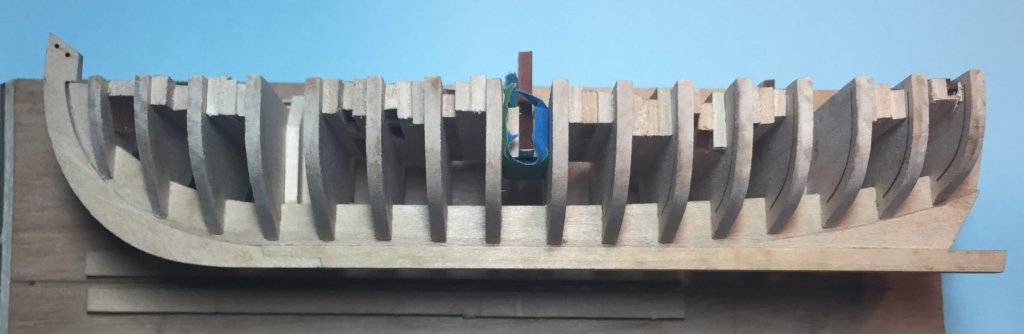
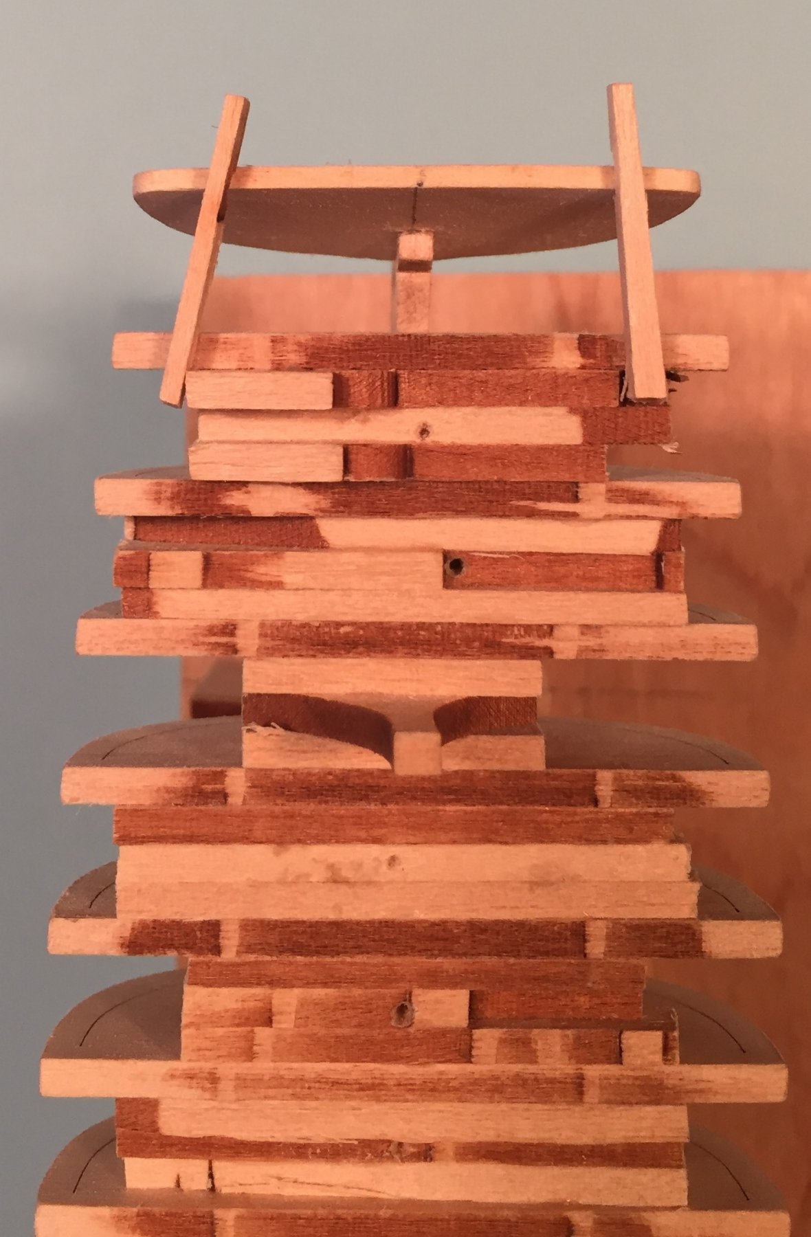
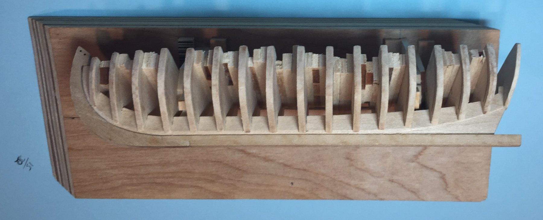
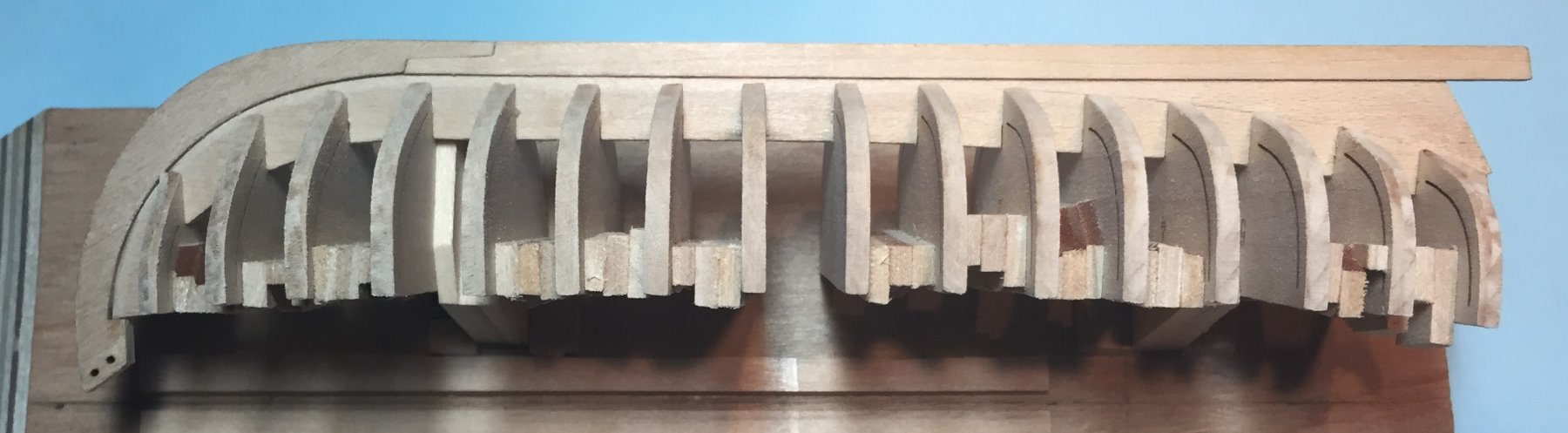
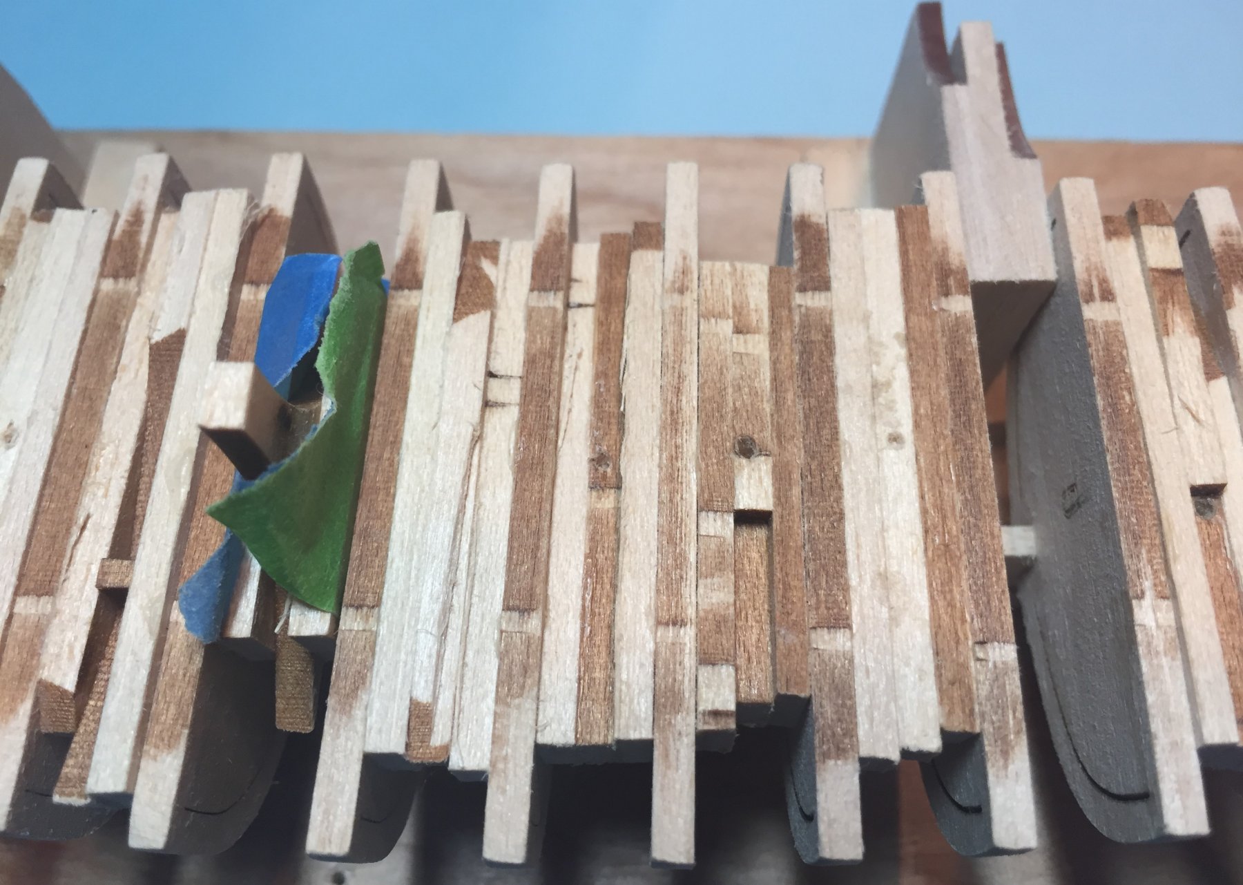
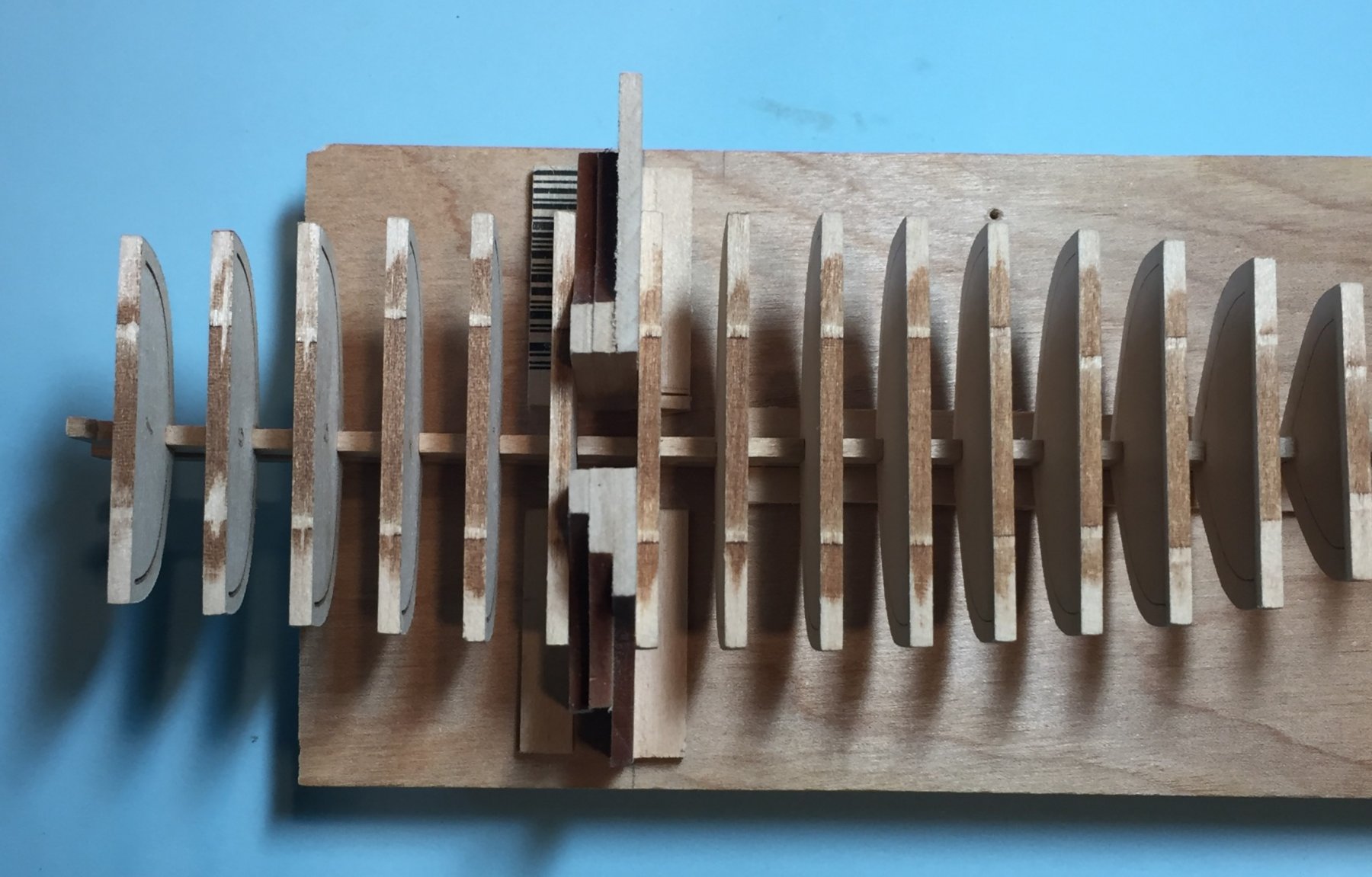
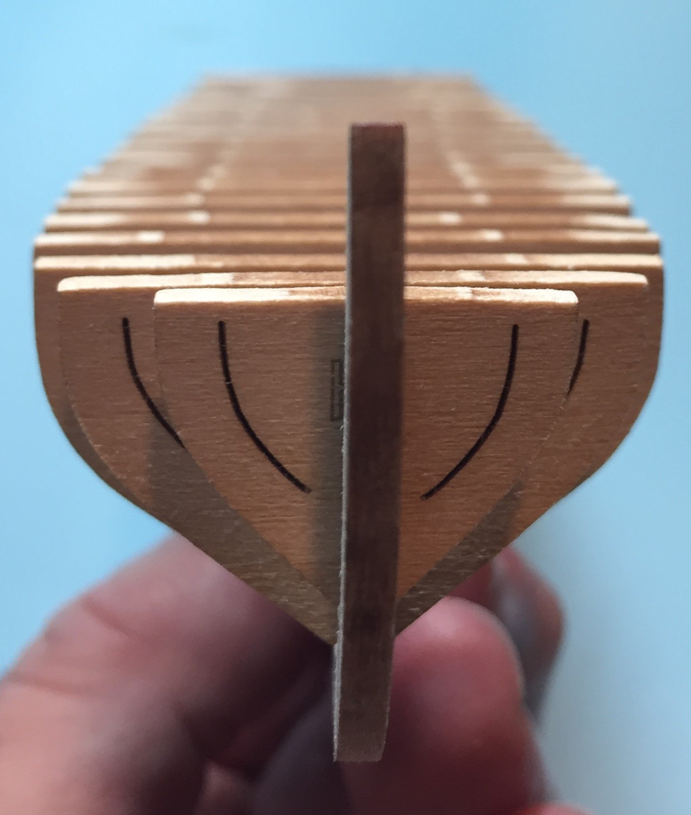
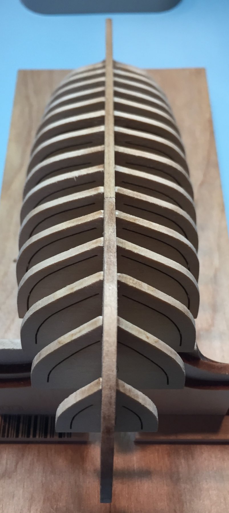
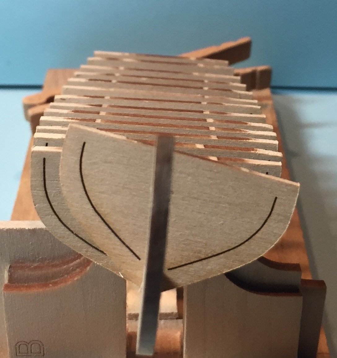
Finish the installation of the spacers. Almost! I proceeded as described above and installed the spacers. I left three spaces blank. The middle space between the center line bulkhead 0 and bulkhead A and two spaces fore and aft where the re-configured building board supports the model. I left the middle space as it was wider than 9/32nds and so the spacers were too narrow. I wrapped a spacer in painter's tape to take up the space and thought that would do the job. I left the spaces blank fore and aft because I want a building board to support the model during fairing and planking. I will show you the photos first, but I must tell you that it did not work out as planned. Here is the hull with spacers installed in all but three spaces. The center is left open and the the spaces fore and aft are for the reconfigured building board. Here are two profile views of the hull. In the two photos above the hull is supported in the reconfigured building board. In the top photo you can see the spacer I created for the center line bulkhead 0 wrapping it in painters tape. Here is another view of the center line spacer. At this point I started to fair the hull, both on the building board and in my hand. I discovered that most of the time is was easier and better to hold the hull in your hand during the fairing process. I also learned that the hull twisted in exactly three locations. I think you can guess where. It actually twisted a lot. So much so that I was concerned about snapping the hull in half. I then placed it on the building board and tried to fair it on the board. I learned that it is much easier to hold it in your hands. The center line spacer wrapped in painter's tape was a fail. It slid in and out too easily. Therefore, I must make three more spacers and afix them to the hull. There are some parts of the fairing process that I am convinced that will allow better accuracy with the hull firmly attached to the building board. So at the time of writing this I am still trying to figure out the spacer situation. After I installed the spacers I snapped off all the handles I left on the spacers. They protruded too far when I mounted the hull upside down on the building board. They snapped right off almost flush with the bulkheads. I am now optimistic that the center portions of the bulkheads will separate when the time comes after planking the hull. Next, I will explain the re-configured building board.
-
Thank you Toni for your input. I did not see your post before I put in my last. I think I was drafting at the same time you were. Thanks for the confirmation that the spacers make the Hull more ridged during the fairing process. The model does twist a lot and keeping it on the building board while you insert the spacers does help to keep it true.
-
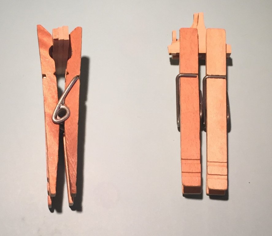
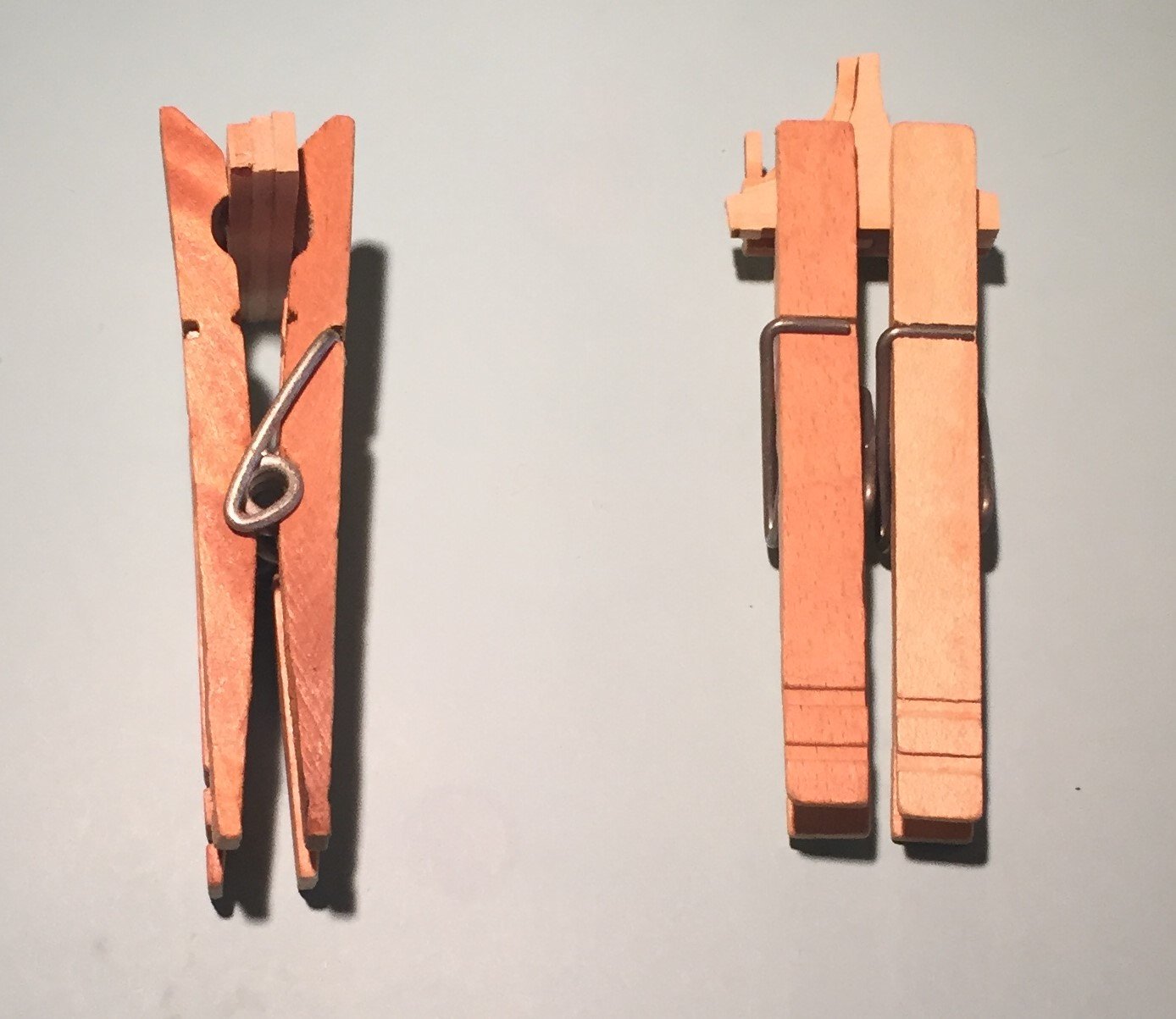
Fitting and Gluing in the spacers. Because in my model many of the spaces between the bulkheads were not the exact 9/32nds shown on the plan*, each of the spacers had to be custom fit to the space between the bulkheads where it was to be installed. I started at the bow and alternated between the front of the boat and back of the boat to speed the job along. The clothes pins I used to clamp the job got in the way of each other if it were too close, and actually were not usable or necessary when I was installing a spacer that was installed between two other previously installed spacers. * I now have three reasons that the spaces are at a variance from the 9/32nds width; a. I was not able to achieve the tolerance by hand with a file in the bulkhead slots and the keel slots, b. sheet A and sheet B from which the parts came from were not uniformly 3/32nds thick from end to end, nor did they match each other, and c. call me crazy but the white glue also takes up space. Thus the spacers are also wider than 9/32nds. I will post this glue question at the appropriate thread here on MSW. This is how I proceeded to install the spacers. 1. I selected the shortest spacers for the bulkhead spaces that had narrower breadth and reserved the longer spacers for the broader bulkheads. 2. I sanded down the width so it would fit between the selected space. I did this on my sanding block from my true sander. I think I mentioned before that this is my favorite and most used tool. Follow the same procedure I described above where you sand 5 strokes on one plain, rotate the piece, take five more strokes, turn over the piece, take five more and rotate again. 5 is a random number, but take no more than 10 at any one time or the pressure from your fingers and hand will cause the piece to be thinner at the pressure point. Do not over sand the piece or it will be too loose and cause you to squeeze the bulkheads to meet it and put pressure on the bulkhead and false keel bond. If you do, put it aside. It will most likely fit in another space, and there is more material in sheet A waiting to be used if you have to make more spacers. 3. When you fit the spacer to the space, you must use care to insure that it is not too deep or too wide so as to cover the laser burn creating the frame on the bulkhead Keep the spacers well in board. Cut to length when necessary. 4. You should fit one spacer at a time, install with glue, then move to the other the other end of the boat while the bond sets. I did however roughly work the next corresponding spacer because I found that when partially installed it put pressure where needed on the bulkhead and spacer next to it to allow the glue to set. Because of the process, the spaces do change width because some pulling and tugging of the bulkheads is inevitable. 5. To glue up, I pushed the spacer below the top edge of the bulkhead, applied the white glue at six points (three on each bulkhead in the space created between two bulkheads) and then pulled, pushed or shoved the spacer upwards to meet the glue. This meant that the glue would smear upwards and not downwards, creating the smallest bonding area to be dissolved later for spacer removal. The same result will be achieved if you position the spacer so it is higher than the bulkhead and position the glue at the same corresponding positions and push the spacer down. In fact I installed a few this way as well as not all of the spacers had those handles left over to help me pull them up to meet the glue. Here is a photo showing glue placement. What you see here is the sparing use of white glue and an easy way to keep track of where you placed it. Note that it is where the bulkhead was attached to the sheet of parts from which it came. You can not see it in this picture but a third dot of glue is at the center(you can see it on the bulkhead closest to you. Also note that this spacer when pulled up will be well inboard the laser cut line for the frame. The third part of the spacer closest to the bottom you can not see because it is hidden by the bulkhead. I then proceeded with installing the spacers. Here is another photo of the process. It is actually the same photo as above but is not cropped. What you see in this photo is that the two forward spacers have been installed, with one of the spacers being used as a brace to aid the bonding of the spacer in front of it, one toward the back of the boat is being stalled and that large spacer in the foreground is one half the gantry wall that has been removed to alter the building board to hold the model for fairing and planking. More on that later. Here is another photo of the spacer installation process. This photo shows three spacers being clamped to bond. The glue spot is noticeable on the fore space. I cleaned it up and removed the excess after the photo. You do not want to create a larger bond than necessary and cleaning up glue over spill is a required modeling skill and is a deterrent to sloppiness and aids precision. Modeling Tip You will note the hole in the forward spacer. To aid in pulling this up into position I took my needle file and drilled it in to create a handle in which to pull up the spacer and when in place I just twisted the file out in the opposite direction. I used this method on one or two of the spacers. This spacer is so narrow that glue was only placed in the center of each of the corresponding bulkheads. Modeling Tip Those clothes pins get in the way!!! Watch your hands as they hover over the model. If not careful, you will knock one of them and potentially damage the model. You will also see that the tooth pick has been modified to apply the glue. Rather than a round point, I found shaving it flat with my #11 blade applied the glue much better during this process. This post is long enough. The next will finish the spacer installation.
.thumb.JPG.c36c6336928820fe3abd0154ee6a3b9c.JPG)
-
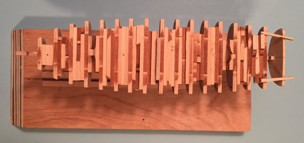
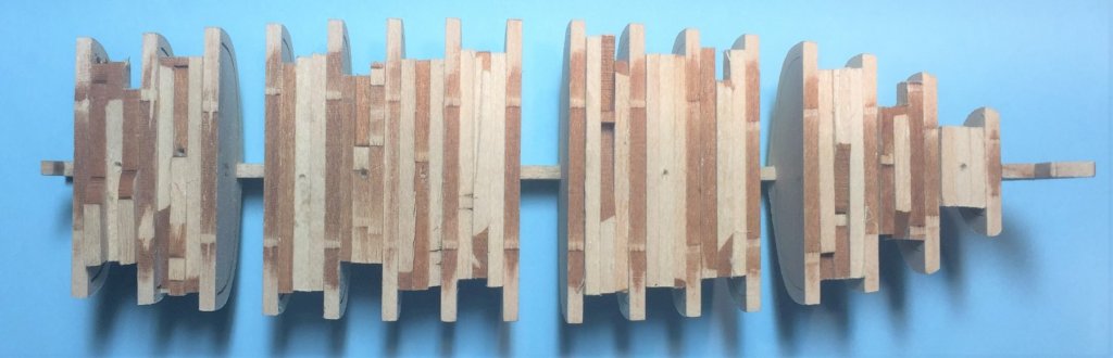
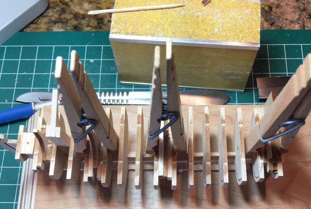
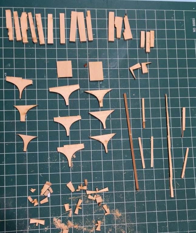
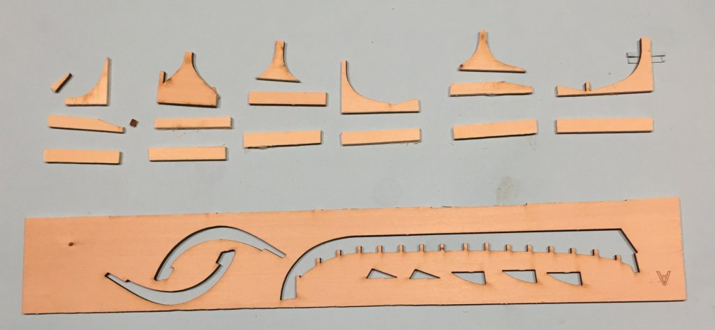
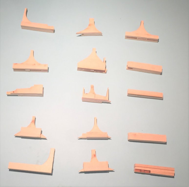
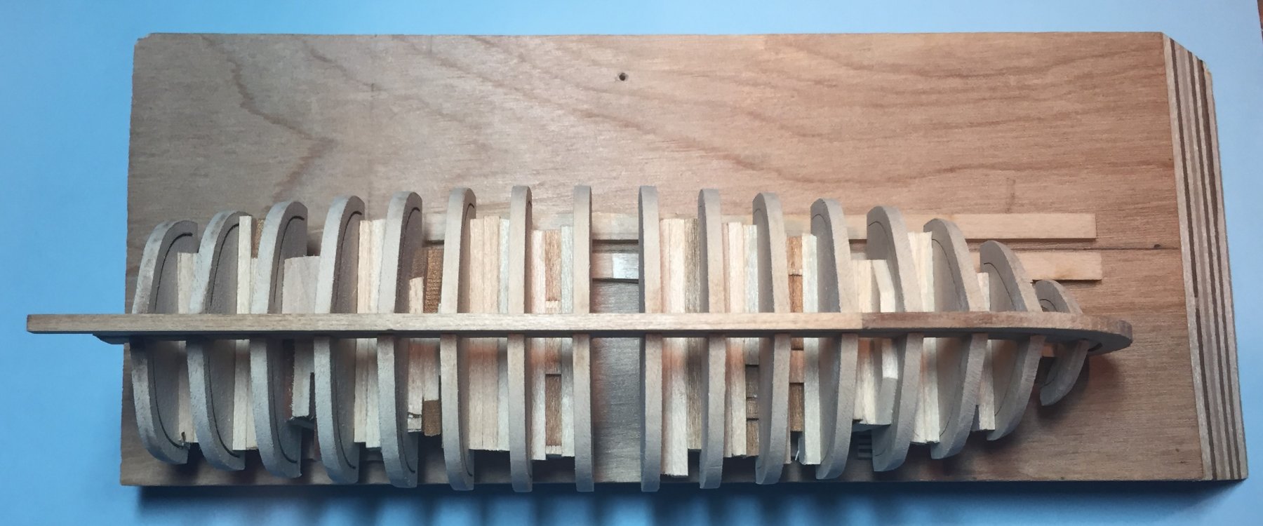
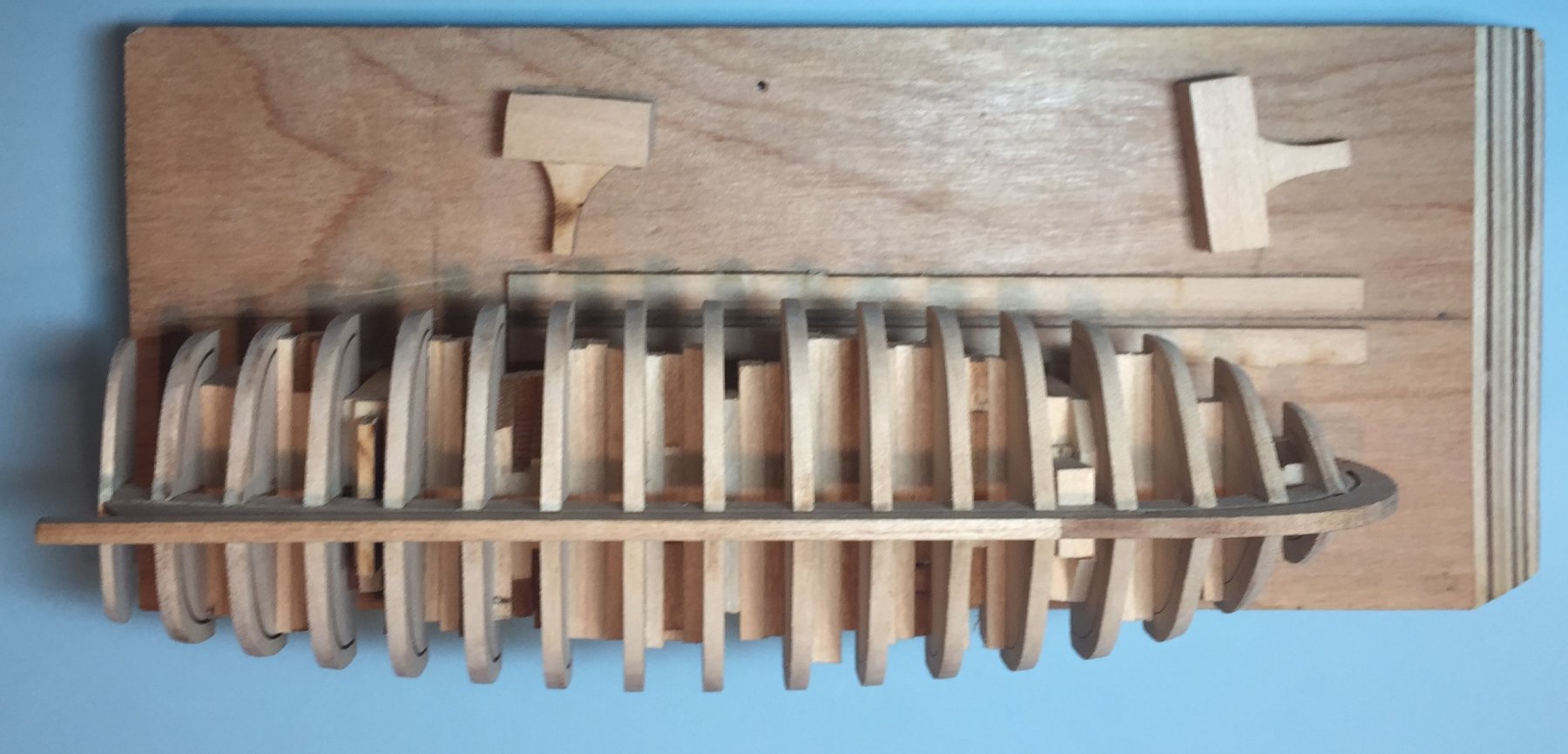
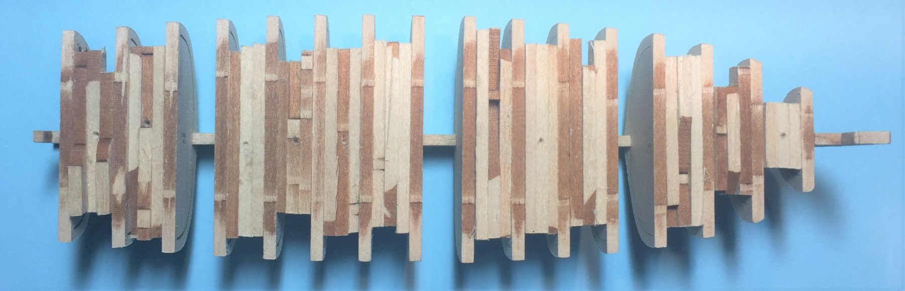
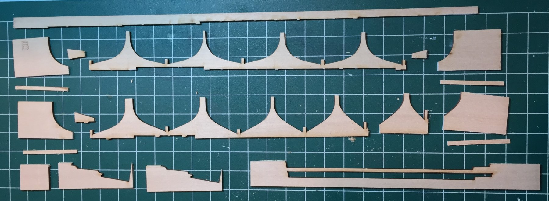
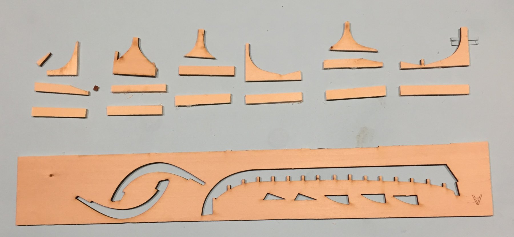
Making spacers to stabilize the Hull during fairing and planking. The hull thus far is very light and very flexible and twists very easily. The flexibility of the hull is a hindrance to the fairing process because as you hold it in your hand it moves. The hull needs to be made stiff during this process. There are two ways to do it. Many here on MSW have glued temporary strips to the top of the bulkheads and they have reported good results with this method. Another way to stiffen the hull is with spacers inserted between the bulkheads. I committed very early on to the making of spacers because in more traditional plank on bulkhead models it is a tried and true, and accepted practice in the community. I also believe for a model so small as this one that it will provide the more stable hull during fairing and planking. I do not know for sure because I have nothing to compare between. Perhaps if I build the Pinnace I will try the strip method and then compare. I am not worried about removing the spacers later because I used the white glue sparingly and alcohol will dissolve the bond. I made the spacers from the flotsam and jetsam of sheet A and B from the kit. Here are the remains of sheet B from which I started. Here are the remains of sheet A I then cut up the remains into pieces of appropriate sizes and lengths for the model. In this case about 1 1/2" long and 1/4" wide. My Zona miter box is 1 1/2" wide. Most of the material in sheets B and A provided for these lengths. They can not be too wide because the depth when inserted in the spaces between bulkheads can not be so deep that that they cover what will become the frames and they may not protrude on the sides of the boat so as to interfere with planking. Here is Sheet B cut up into bits and pieces to make the spacers. Here is sheet A cut up into bits and pieces to make the spacers. After harvesting the wood into the bits and pieces I sorted them by length and put them into groups of 3. To do this I selected the best matches among them for size, both length and width. I kept them as long as possible. You can always shorten them. I then began gluing them up. I used clothes pins for clamping. I also made sure that on one end and what will be the bottom that the the pieces were flush with one another to provide for two clean edges. The spaces in the sheets where the bulkhead came from I left on the spacers. They were a big help later when inserting them between the bulkheads. Clamping up the spacers. 15 spacers all glued up.
.thumb.JPG.cd4ab83ef238c41ee5b3c8eb658314b2.JPG)
-
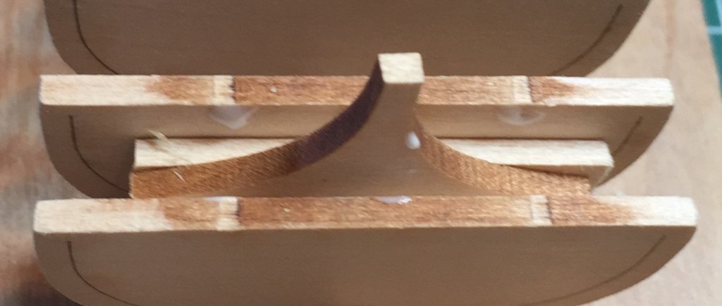
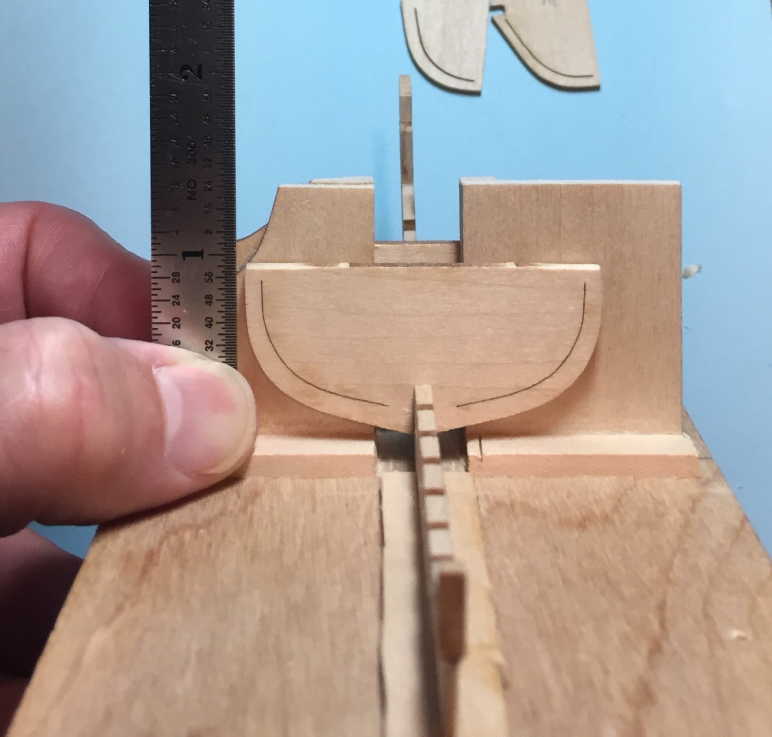
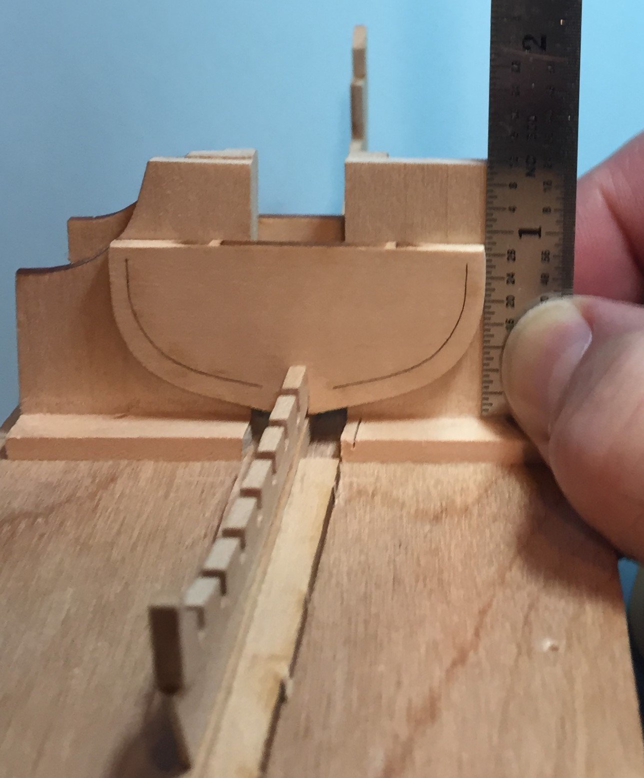
I HAVE DELAYED ATTACHING THE TRANSOM. Like many before me I have not attached the transom to the stern yet. The reasons for this are that: a. The model is very fragile. People have warned me about this, and name it as a reason that it is not meant for a beginner. At this point in the build I am still unable to agree with them that this should be a reason against making it a model for the beginner. Perhaps it will teach a beginner to have a Lighter hand and touch rather than a heavy and brute force hand that some larger less fragile kits invite. b. The transom is very exposed and therefore prone to accidents and the resulting damage. c. Very little supports the transom. There is no slot. d. I am still making decisions on how I will plank the boat and how I will instruct the beginner to plank the boat. These decisions will dictate when the transom goes on. I am leaning toward a hybrid method that combines some spiling that is prototypical boat and ship building and some edge bending that is explained in the instructions to the kit. My idea is that I will make the garboard plank and perhaps the 1st broad strake from material twice as wide as that provided in the kit, and also make the sheer plank(in this boat the substitute for the wale) out of wider material. This would be prototypical boat building. This would cut the work load and perhaps provide for a faster planking job as you eliminate 6 planks in the process. Also, If I plank from the keel up, the cut of the garboard will establish the sheer line at the rail automatically, or is this wishful thinking? All the books say attach the garboard and wale, and then plank in between them. PLANKING THIS LITTLE BOAT IS THE NUMBER ONE REASON GIVEN TO ME TO SUPPORT THE POSITION THAT IT IS NOT A BOAT FOR BEGINNERS. At this point I still disagree with this proposition. After all, you have to plank a boat sooner or later. I look forward to your comments on this issue.
-
Miter boxes----What is the best one.
roach101761 replied to roach101761's topic in Modeling tools and Workshop Equipment
Thank you Kurt, Jack and Richard. I have the UMM micro saw and box pictured above. It is very nice for small work and I highly recommend it. UMM also makes one with a V slot or groove for round material. I also highly recommend that. Richard thanks for the review of the Zona box. I will probably order it today and pull out my Micro Mark catalog and see if it is time to suffer some shipping costs. The mid west box I constantly see at Michael's, Joanne's and Hobby lobby. Time to find a coupon. Am I correct that I can easily place a piece of wood on the bottom of the deeper boxes and that will shorten the depth so I can use my Zona 52 and 42 TPI mini saws in the bigger boxes? -
I am on the search for a new and better miter box. I never use my bright aluminum xacto miter box. I learned long ago that it is too hard on my saws. I have been using a plastic Zona miter box, it works great for a while, but my saws are too hard on the plastic box. The plastic is a bit soft. Do any of you have any suggestions? Whats the best one out there?
-
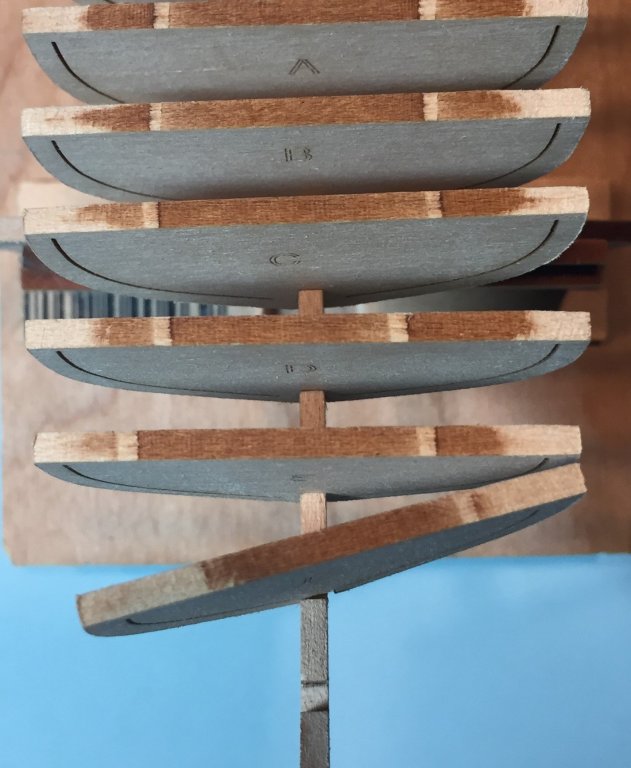
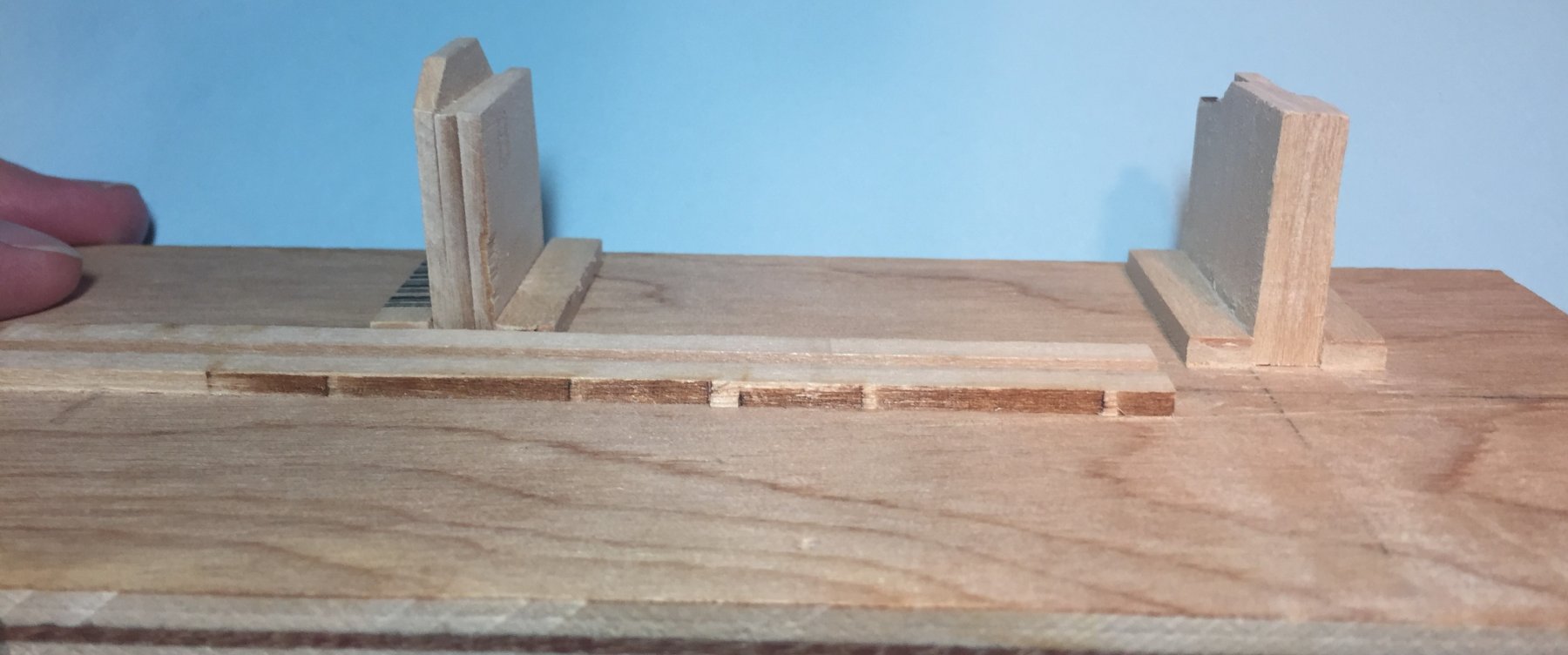
LESSONS LEARNED in setting up the bulkheads. 1. Trying to set two bulkheads up at the same time on this little model was a total fail. The model is very light and the false keel and keel assembly with the bulkheads twists very easily. I could not see the tops of each bulkhead to properly line them up with each other because they were on opposite sides of the gantry wall. Any pressure on one bulkhead would tend to alter the bulkhead on the other side of the gantry wall. And frankly, the tolerances required between the bulkheads was not achievable for me by hand with a file or emery board. I was unable to prep the slots in the keel so that the face of the bulkheads were exactly 9/32nds apart. Some spaces made the tolerance, but most were short or a bit long. As a result the the model would not fit on the building board with a bulkhead on each side of the gantry wall for many of the spaces. Two fit well, two more I can force it but it will put stress on the bond and perhaps break the bond. Here is a photo of the best fitting on the building board between bulkheads. 2. I did not use enough glue and was too sparing with it. After the Hull is planked and it is time to snap all those bulkheads and separate them from the frames and then sand down the false keel and frames I concluded that the only contact point of each frame on the keel will be where each of the remaining frame parts touch the keel next to the center line. Therefore I only put glue in the bulkhead slot. This was a mistake. The structure was way too fragile, and as I have stated before the structure twists very easily. Needless to say the bonds on the bulkheads failed. 3. White Glue is great! White Glue is very forgiving! a. When the bonds failed, there was no damage to the wood. The alcohol applied to the bulkhead and keel where the dry glue remained dissolved it as advertised. I scraped glue off the keel and bulkhead with my number 11 scalpel blade. b. You get a do over with white glue. This is why I choose it for this project geared to the beginner. CA and yellow glue are too hard to remove. CA actually plasticizes. I reset the bulkheads when they failed using much more glue and applying glue to the fore and aft sides of the bulkhead. The clean up was easy as the excess glue was squeezed out in beads which I could lift and remove with the #11 blade. C. YOU GET A DO OVER!!!!! So all the bulkheads are in, you are feeling pretty good and you begin to examine your work closely and start thinking ahead to the fairing of the hull and planking. Suddenly you notice that one or two of the bulkheads are sitting high or low. A problem. With white glue all you need is a fine paint brush and a little alcohol. Apply the alcohol to the bond, being very careful not to let it drain to the false keel and keel interface, and wait half a minute and work the part loose. Remove all glue remnants, and do over. A huge advantage for beginners. 4. When re-setting bulkheads, my 9/32nds gantry wall got in the way because the spacing between bulkheads are not all 9/32nds. If two in a row were out, re-setting one was OK. However, re-setting bulkheads with short spacing had to be done by eye. I used spacers to keep it parallel with the bulkheads fore and aft. These spacers were made to support the hull during fairing and planking. (explained later) 5. For future models I will not abandon my fixed gantry wall idea. In traditional plank on bulkhead models, spacing between bulkheads is greater, so I should not have a problem. 6. Removing the char from the tops of the bulkheads was a mistake. It made measuring their height port and starboard more difficult. Here are the photos of my result


-
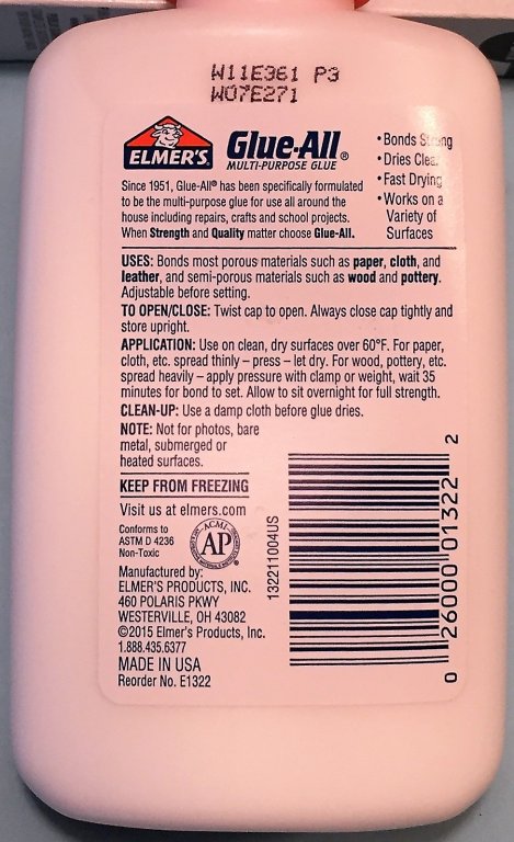
USE OF THE FIXED GANTRY BUILDING BOARD-----SETTING UP THE BULKHEADS Thank you Ryzuhr for your kind words and support. Now on to setting up the bulkheads. For this segment I will post the picture and then underneath the photo explain it. I probably did not take enough photos, but what I have will be adequate. This view is from the bow to stern. I began by setting Bulkhead head A which is forward of the center line bulk head 0. I did this by having the stern of the keel pass through and hang off the back of the building board. This is where the building board showed itself to be too short. When I lifted the fore end of the board, the stern portion of the keel struck the work surface and pushed the keel out of the keel slot and off the board. LESSON LEARNED----NEXT TIME I WILL MAKE THE BOARD ABOUT 160% THE LENGTH OF THE KEEL OR THE FINISHED HULL TO THE STEM and create the keel slot end to end. For long hulls this may not be possible as the board will be too big to deal with. But for models for up to 12 inches long it might work very well. Also, after the bulkheads or frames are set up, you can always cut the board to a shorter more manageable length. This view is from the stern to the bow. What you see here is the center line bulkhead 0 being placed into the false keel and flush with the fixed gantry wall. Its height on the fixed wall is being measured with my steel mechanical ruler. This one is in imperial units, and has 32nds on side and 64ths on the other. Basically the same measurements on each side making measuring and comparing port and starboard a little easier. Bulkhead A is already in place and glued in. Please remember that the space between the center line 0 bulkhead and bulkhead A is greater than 9/32nds as this is where the windless will be located. I decided that I would work the model both fore and aft alternating the bulkheads. This is the same stern to bow view This time the Starboard side of the bulkhead is having its height measured. The procedure I used is as follows. 1. Dry fit the bulkhead to make sure it fits well and no further adjustments are necessary. BASIC MODELING TIP What do you do if the bulkheads are too loose because you overworked the keel slot or bulkhead slot. You us paper to shim the bulkhead. My center line bulkhead 0 ended up too low. I raised the level with a small piece of paper of the proper thickness. Another bulkhead was too loose fore and aft. I shimmed that one with a small strip of cash register receipt paper. In both cases I cut a thin strip the width of the bulkhead. I pre-glued the strip inside the center line bulkhead then cut off the excess. Fore the cash register paper I tacked it to the bulkhead above the slot. BASIC MODELING TIP 2. Also have all you tools ready to use for the gluing up procedure. This means the open glue, applicators(I use use round tooth picks--another required tool), ruler,clothes pins. You MUST also have all those tools ready to remove excess glue. These include my #ll blade with craft handle or scalpel handle, damp q-tips, damp paper towel and small container for additional water in case you need more dampness. I tear up the paper towel into small sections. Notice I said damp, not moist. Moist is probably too much water and may attack the bond if you are not careful. 3. Apply glue to the the three surfaces of each slot in the false keel and to the three surfaces of the bulkhead slot. Apply glue on the fore and aft sides of the bulkheads where the keel slot will rest. 4. Hold the false keel and assembly thus far in your hand. Seat the bulkhead into the keel slot. Work quickly. 5. The excess glue was pressed out of the bonding area. Quickly clean it off with blade, and or damp q-tip or damp paper towel. Work quickly. 6. Place the keel assembly into the keel slots and move the current bulkhead (the one you are gluing up) up to and flush with the fixed gantry wall. 7. Adjust by eye first. You will be surprised at how much your eyes tell you, and how much they do not. Adjustments are made by putting pressure on the starboard or port side. 8. Measure with your ruler on port and starboard to insure each side of the bulkhead is at the same height. 9. Carefully apply a clothes pin to hold it. You have to make sure that when you put the clothes pin on one side it does not tug the bulkhead and move it out of position. Apply the second clothes pin to the other side taking the same care. 10. If you can reach it, remove any more excess glue that has been exposed. DO NOT UN-CLAMP THE ASSEMBLY FROM THE BUILDING BOARD AND GANTRY WALL. Any glue you can not reach now can wait. There will not be that much, and it is the number one reason I am using white glue. 11. Wait. Then wait some more. Especially for the the first two or three bulkheads. The instructions on the bottle of Elmer's Glue All says to apply pressure with a clamp or weight, wait 35 minutes for bond to set. Leave overnight for full strength. See the label below. 12. After you are sure the bond has set remove the clamps and back the keel in the keel slot so the bulkhead is off the fixed wall. Wait a day or two to remove any glue. You do not want to disturb the bulkhead seat or its bond. The next segment will be the lessons learned and the continuation of setting up all the bulkheads.


-
FINAL ADJUSTMENTS TO AND GLUING IN THE BULKHEADS. I did not take as many pictures as I should have during this process. I was building the model instead. However, below are two contrived photo's that exaggerate the corrections that you must take on two axes. The third photo is a very cropped repeat from above showing the fore and aft axis that you must correct. The forth photo shows the last axis you need to correct. That is where the bulkheads rest on the false keel in the vertical. There is more text below that photo. You will notice from this photo that the bulkheads do not rest in a gentle sweeping line from the mid line forward. The forward bulkheads appear to be to high in relation to the middle. After a careful look at the plans and examination of the 1/32nd thick planking material I decided that all the bulkheads except the center bulkhead were high. The center bulkhead was actually a tad bit low. More adjustment was necessary before I could begin to glue it up. I did this very carefully to get close leaving the final adjustment when I glued it up.
.JPG.5ae1544c903aebd9578f7b6f1e42ffc8.JPG)
.thumb.JPG.283d7222cd8c0c7e2cd087a5b08f2ea9.JPG)
-
Scientific stuff on white and yellow glue--Knowing how it works is useful and can not hurt. At my ship model club our members are from diverse working backgrounds. One of our members is a retired science teacher. If you want to know how and why something reacts or acts the way it does Wain Garrison is the man to ask. Recently I asked what the differences were in white glue and yellow glue. He wrote up the answer and passed it out to our club. With Wain's permission to share it readily given, here it is. TWO WOOD GLUES Polyvinyl acetate Polyvinyl acetate (PVA), also known as “white glue” or “hobby and craft”, is non-toxic and very easy to use, but hard to repair since most glues (including PVA itself) do not adhere well to hardened PVA glue. PVAs will creep under constant load. Elmer’s Glue-All is an example of a PVA adhesive. As an emulsion in water, PVA emulsions are used as adhesives for porous materials, particularly for wood, paper, and cloth. Polyvinyl acetate is prepared by the polymerization of vinyl acetate monomer. Vinyl acetate is an organic compound with the formula CH3CO2CH=CH2. Aliphatic resin Aliphatic resin emulsion, commonly referred to as “yellow glue” or “carpenters glue”, has a similar use profile and relative ultimate strength as PVA. The two glues differ in grip characteristics before initial set, with PVAs exhibiting more slip during assembly and yellow glue having more initial grip. Brands include Titebond and Lepage. Famous “yellow” wood glue used in modeling and professional applications where hard woods are used, dries crisper than PVA giving better sanding especially with balsawood. Will not pull joints as it sets, resulting in better dimensional stability important for airframe construction. Also sets at low temperatures and is water resistant making it ideal for model boats. KEY LESSON FOR US HERE--- "...but hard to repair since most glues (including PVA itself) do not adhere well to hardened PVA glue. " This means that before you can re-glue or re-attach a part or element with more white glue you must clean off all the old glue. Use alcohol for this purpose. The alcohol will soften the glue by dissolving it making it easy to wipe off or scrape off.


.JPG.66fa192594bcc2952b67a3f83369c901.JPG)

.JPG.f399764cec1f91b7eaae78a36af47bdb.JPG)


.JPG.34716a429c4ccbb3ff12f138f2a364a6.JPG)