HOLIDAY DONATION DRIVE - SUPPORT MSW - DO YOUR PART TO KEEP THIS GREAT FORUM GOING! (Only 13 donations so far - C'mon guys!)
×


roach101761
-
Posts
204 -
Joined
-
Last visited
Content Type
Profiles
Forums
Gallery
Events
Everything posted by roach101761
-
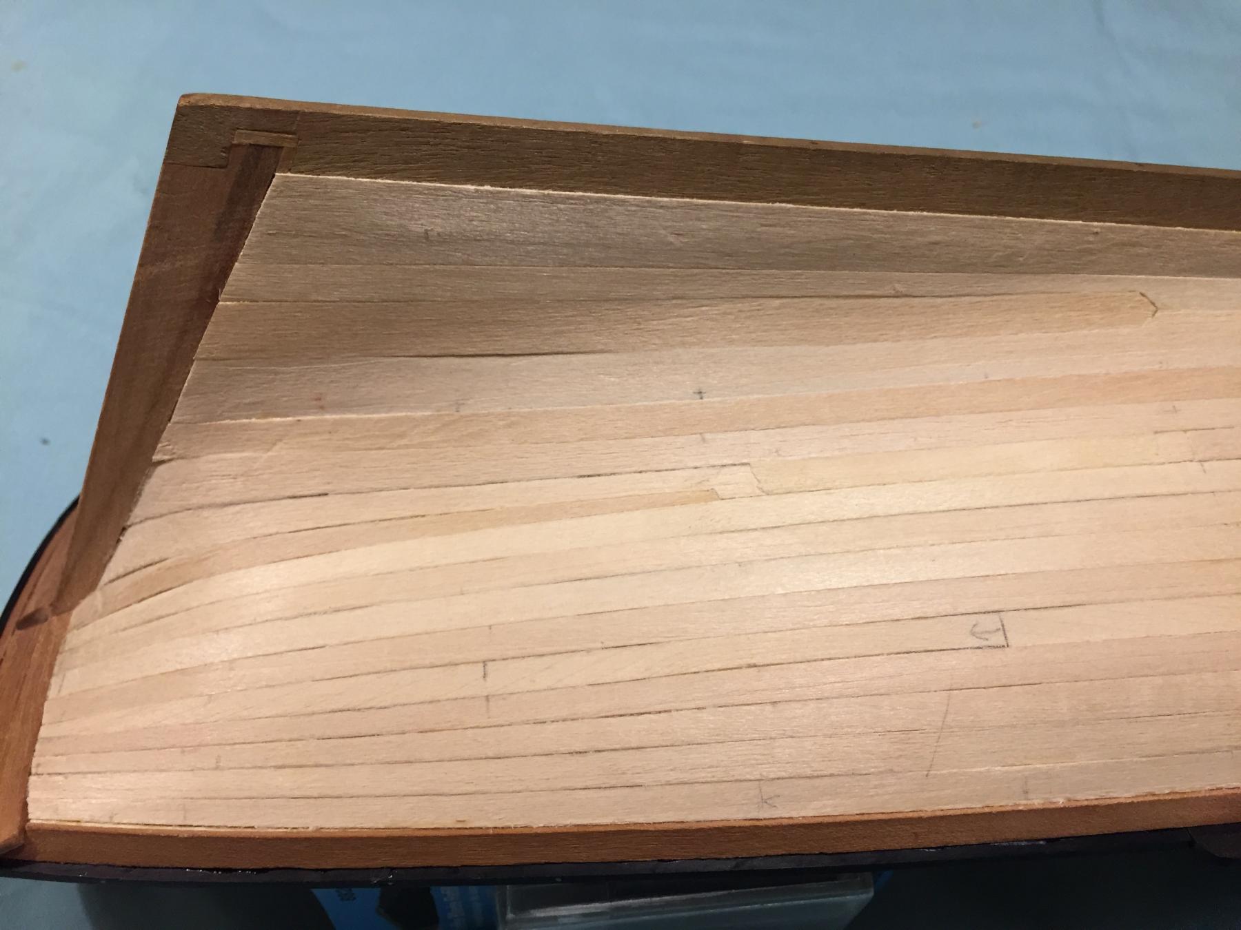
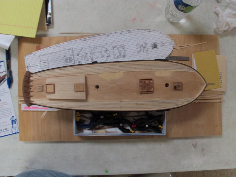
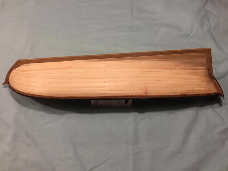
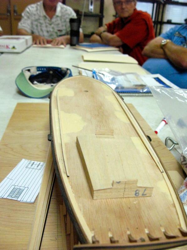
Back to planking the deck. As you can see in the photo below I progressed with my deck planking from the outside to the inside. I also have made progress on major components of the deck furniture. I will discuss those at a later time. As you can see the deck planks are curved and tapered both at the bow and stern. All of the deck planking butts will meet in the middle portion of the deck. You will note that I have not randomly cut scale 20 foot planks and fixed them to the deck in some pattern dictated by the plans and other modeling sources. I explain my choices in further posts or I may edit this one so refer back to it from time to time. You can see the deck plan from the plan set with the uniform plank lengths next to the model. The deck furniture is not attached at this stage. It is just placed on deck to help with planning the placement of the deck planks.
-
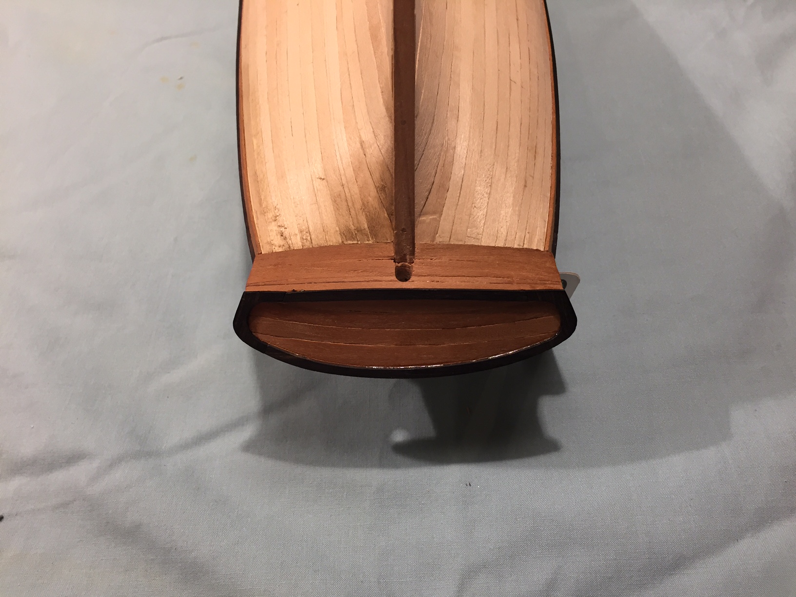
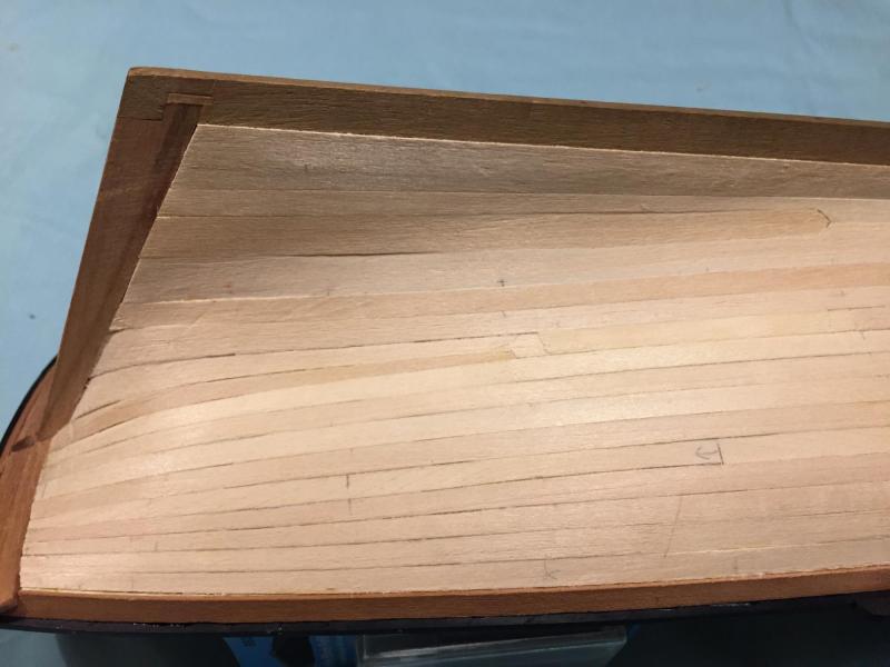
These are two photo's of the stern of my model. They are being posted to show the planking that I described above. You should be able to see the two stealers I used in the stern. They also show the wider planks that were necessary in the stern to take up the additional space created by the significant keel drop. I will discuss the make up of the stern and transom in a later post and will probably re-post the photo again when I discuss the stern.
-
Sorry for the delay in my reply but I had to pull out my research to be sure. I have not been able to confirm that any ships were built that conform to the Large cutter (79 or80 ton) plan prepared by William Doughty in 1816. The AL kit conforms to the large cutter design but is not the Dallas, as the Dallas is confirmed to be the Medium size Doughty cutter design of 51 tons. Although I can not site specifics, I believe that there are confirmed ships of the 31 ton plan as well. According Marc Mosco of Model Expo, he explained to me in an email that AL marketed the kit to ride on the Hollywood fame of the popular television series Dallas, staring Larry Hagman.
-
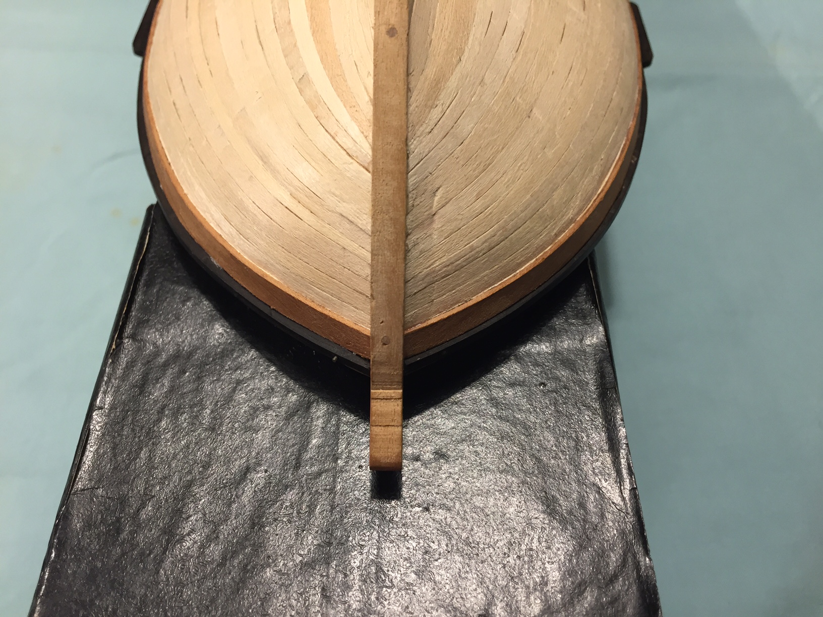
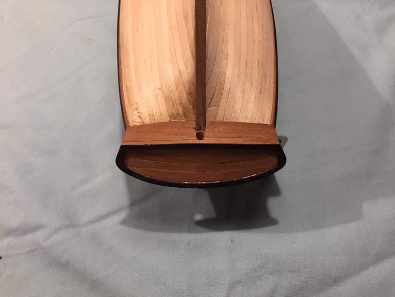
Here is a photo of the bow of my ship. You can see how narrow the bow planks get, however only one of them is less that 1/2 of the original planking stock. This photo also shows what a beating a model can take while you are working on it. The hull still needs some sanding and filling in spots before I copper plate it. This photo also shows the lack of any drop planks in the bow. Perhaps I could have used at least one, but then the plank would have not been in one piece and the exercise of this planking job was to learn how to plank in a prototypical manner, so it was a necessary exercise to cut and shape each plank to fit the space.

-
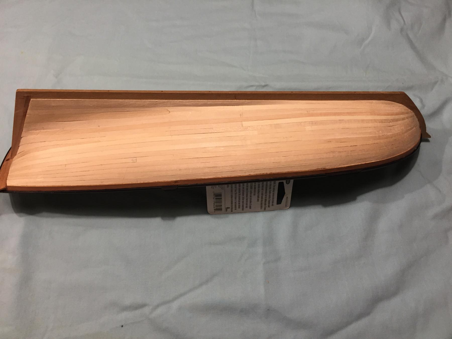
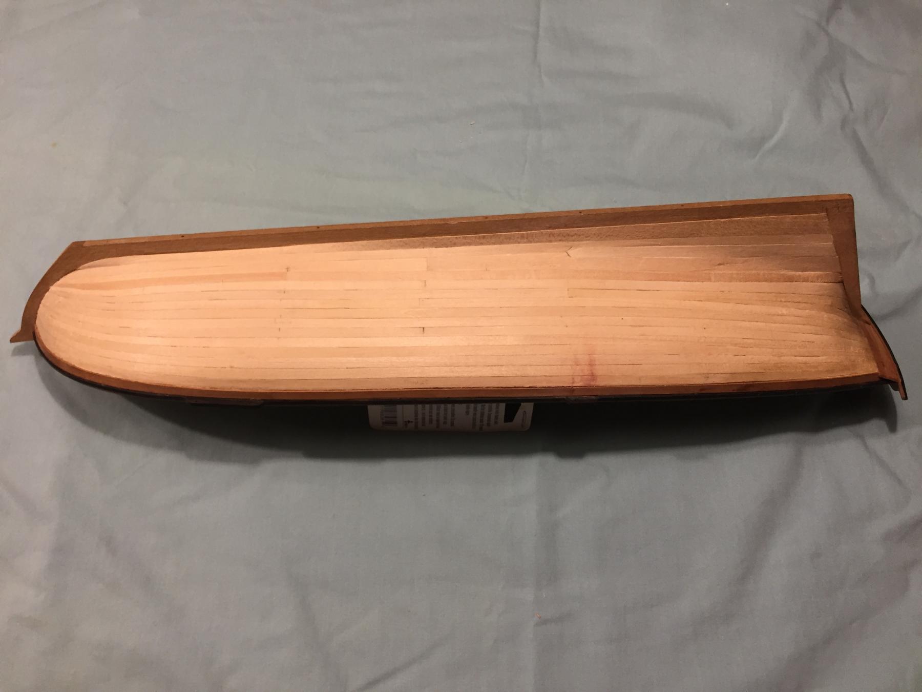
Now, back to the planking. These two photo's show the port and starboard sides. There are 15 planks on each side. The planks were laid in three(3) strakes. The widest part of this hull is at station #4. This ship has an extreme Baltimore Clipper hull form. The space in the bow makes for very narrow planks and at the stern the planks get very wide. In the stern, to fill up the space I used wider stock and shaped the planks. I used two stealers in the stern. In the bow I DID NOT use any drop planks. Most of the planks did not go below 1/2 of the plank width of the stock I used, Actually looking at the model now, only one (1) plank violated this rule. The first nine (9) planks down from the wale were laid in one piece stem to stern. I laid in the stem first and worked my way aft. The 10th plank was laid in two parts with the butt at station Six (6). The aft portion of this plank received the first stealer plank. Plank eleven has its butt at station five (5). Plank twelve (12) has its butt at station four (4). Plank thirteen has its butt at station five (5) on the starboard side only. This plank is cut to receive the second stealer in the stern. The port side is in one piece. I recall that I messed up the stem part after the stealer was cut correctly. I did not want to do it again so cut the port plank at station Five (5). Plank Fourteen (14) and the Garboard are all one piece. If you look you may see what appear as short lengths of plank and more butts. I milled some of my planking stock to very thin thicknesses and tried using them as fill. Some of the planks developed depressions between the bulkheads. For the most part it was a success. However, I have more sanding to do and will use some filler before I copper the hull. The port side. The Starboard side.

-
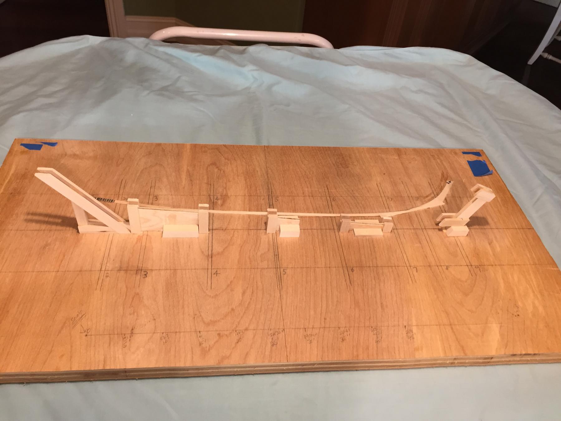
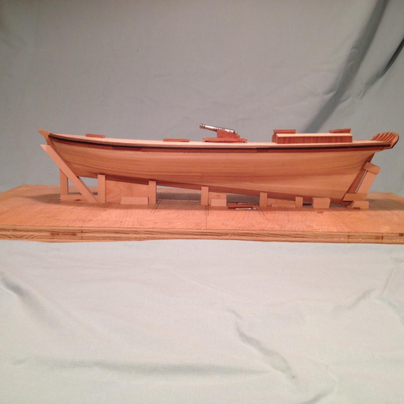
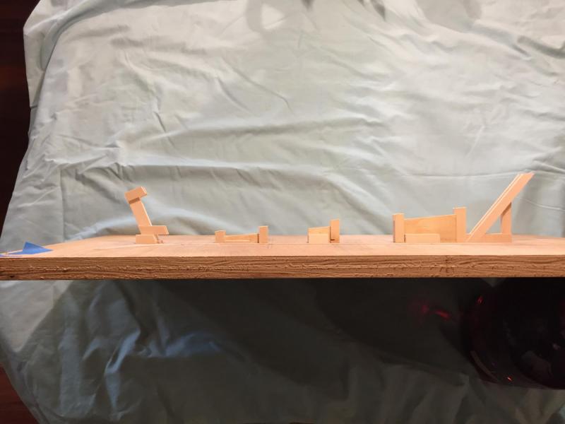
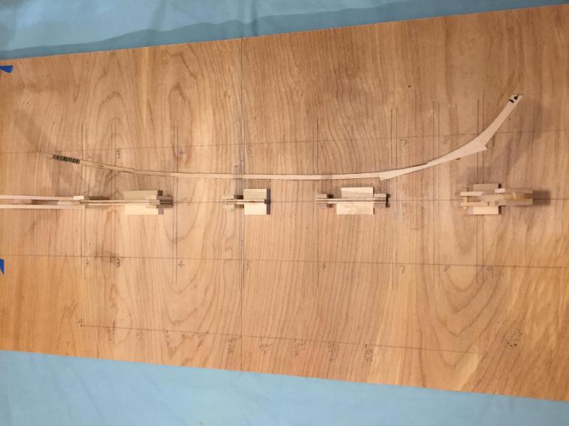
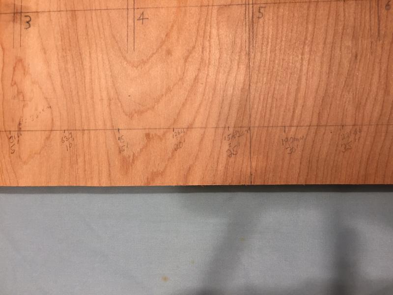
Here are a few pictures of my building board. This first picture shows it from the side. You can see the angle necessary to insure that the waterline was parallel to the the building board. This second photo shows how I marked all the station lines for the bulkheads. It also shows the scale I drew on the board to measure my deck planks. Station two (2) is the bow. This photo shows the view from the bow to the stern. It also shows the guide I made to form and bend the margin plank and for which I used to cut and fit the first planks on both port and starboard. This is a close up of the scale for the planks on the board

-
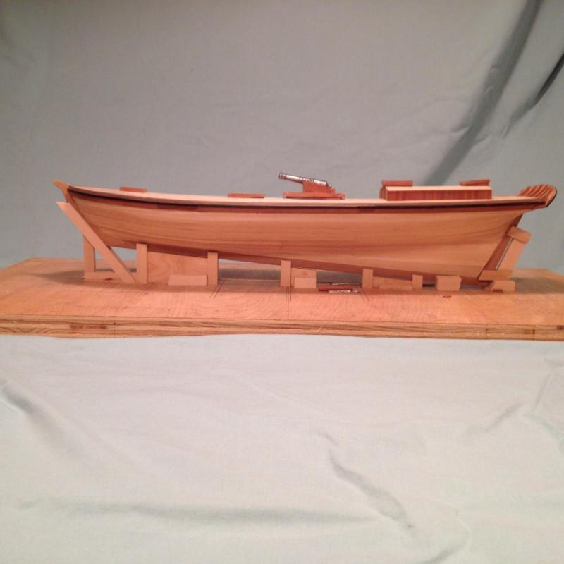
This photo was taken of the ship after a lot of progress was made on the model. I am posting it now for two reasons. The first is to show the planking job I have done on the boat, and the second is to show the building board that the model is being built upon. I will provide more detail on the other visible elements at a later time. First the planking. At this point all should know that I have not used much of the wood that came in the kit. I used the false keel and bulkhead assembly, keel, stern, stem, and the ply wood false deck pieces provided in the kit. I planked the model with bass wood. I have always known that I would copper plate the hull and cover up the planking. I planked the hull in several strakes using proportional dividers, creating a port and starboard plank for each side, prior to moving on to the next plank. This was my first effort at prototypical planking and I used Jim Roberts' book Planking The Built-Up Ship Model as well as Don Dressel's Planking Techniques for Model Ship Builders. Both of these books were a great help to me for this model. I highly recommend both of them. If memory serves, I attached the wales first. They are made of cherry. I then attached the garboard followed by the first broad strake. Both these planks are much wider than the normal planking stock. I then measured and set my planking battens. Each of my strakes contained five (5) planks. I set the strakes by using the tick strip method of measuring the bulkhead at the widest point of the ship. Then divided the distance to determine the number of planks it would take and the determined the number of strakes. I will provide more details on the planking in further posts. The model is not out now, I will take additional photos of the hull and provide further descriptions. Now the building board. It is 3/4" cabinet quality birch plywood. I am embarrassed to admit how many years it has supported the model. I has been very stable and has remained flat. In order to support the model level at the water line it was necessary to figure the angle so as to build the supporting structure to rest the keel. I took the measurement directly from the kit plan sheet that depicts the completed model profile. Believe it or not the printed plan sheet had the waterline parallel to the edge of the paper. I do not remember the angle now, but you can see the result. More on the building board and more photos later.
-
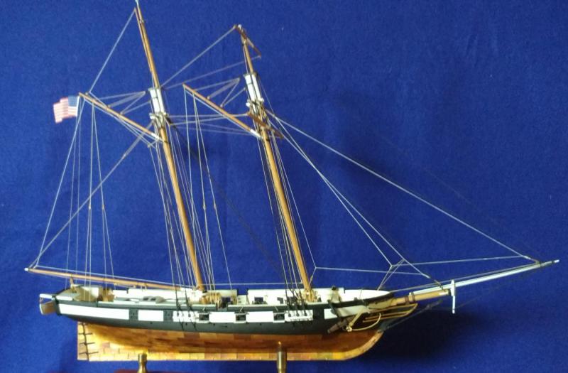
This is one of the earliest photos I have my AL Dallas kit. At this point the hull is fully planked, the rubbing wale and the four channels are attached to the hull. More on the planking and rubbing wale latter. After fighting with the thick plywood deck it need filling in several spots before I could begin my deck planking. In this photo the margin plank is in and I begun planking from the outside in. Believe me, EVERYONE told me to start from the center and work out. Normally that would be the correct path, but I could not because of the deck planking pattern I chose for this ship. I am a believer in the curved and tapered deck planking concept. I was not going to cut my deck planks into 20 to 25 foot scale lengths and place them on the deck. For a vessel so small I believe much longer planks would be used and there would be far fewer butts in the deck planking. Also this ship was built in the United States in 1815 or shortly there after. Much longer cuts of wood were available in North America although the supply was exhausted in Britain and most of Europe. The trees could still be floated or carried overland to New York rather than transported on a ship. In order to work out the plank pattern that I desired it was necessary to work from the outside to the center. This picture also shows that I have roughly framed up the cabin so that I could properly located it on deck. I was always disappointed with the design of the transom in this kit. An oval of plywood was provide in one piece to be bent and glued into place with no supporting knees. As you can see I have made a major modification to the stern which I will describe in greater detail latter.
-
I have decided to start a build log of the Artesania Latina kit Dallas. The model is already in an advanced stage. I do however have a few photos of the the process after the hull was planked. Some of the text and a photo or two, I have copied from a previous thread I started on the splash boards that are featured on the three William Doughty revenue cutter plans of 1815. The two paragraphs below are from my earlier thread. I have been Kit bashing the AL Dallas revenue cutter. I have done a lot of research and collected a lot of materials on the Doughty revenue cutters circa 1815. See Chapelle's History of American Sailing Ships, chapter four. By the way, the AL kit is not the Dallas, as it depicts the 79 ton cutter. The Dallas was the 51 ton Doughty cutter. I have also collected the plans of the the Ranger,(a Corel kit) a non existent ship, which is also a Doughty revenue cutter circa 1815. The three Doughty cutters ares 31 ton, 51 tons and 79 tons. Prior to beginning my build I collected a lot of research on Dallas. Then one day I was Reading Don Canney's book US Coast Guard and Revenue Cutters and he stated that Dallas and It's sister Surprise were the 51 ton Daughty design cutter. I was shocked. Chapelle says 80 tons. How could this be? So I called him, told him of my shock and requested his source. A few weeks later he called back and directed me to the David Gelston Papers at Mystic Seaport. Gelston was the collector of revenue in NY City. The papers contain the correspondence From Secretary Dallas that orders and directs its building by Adam and Noah Brown. The papers contain the contract and later the certification of the ships measurements. I began researching more and collected a research partner along the way. YUP 51 tons. No doubt. I am in the process of writing an article or two. I have a very rough draft so far. An other problem is that two vessels were built at the same time. One went to Savannah. The other went to Massachusetts. Not South Carolina. I now call my model the Ship that Is NOT the Dallas. Still looking for data to determine a name for any 80 ton Cutter built to the Daughty large plan. The Ship was contracted for in August of 1815, Launched in Oct 1815, Delivered to its captain in New York City in Dec. 1815 and is reported at Savannah shortly before the end of the year. The ship served until Nov. 1821 when it was sold out by public auction in Charleston SC. I have a complete copy of the Coast Guards Record Of Movements. For the early boats there are a lot of errors and inconsistencies in this work.
-
After the above post I went looking on line for copper and other metal products. I was was looking for a gauge or thickness chart for copper. I have not found one to my liking yet, however the are readily available on line. When I find the right one, I will post it here, or ask the administrators to put it the pdf files. I will look there also. I looked a few web sites that this deserves a look. Lost of neat stuff. They also make patina solutions in green, blue and antique brown. http://basiccopper.com/?gclid=COiu9P_X9tECFQYGhgodUscLsQ
-
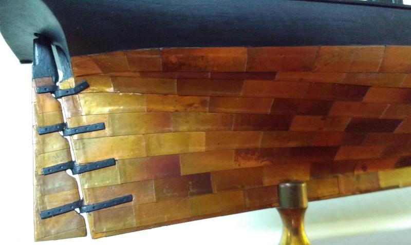
To the Naysayers These two photos belong to the New Bedford Whaling museum. If you have never been I can tell you that it is an excellent museum and it is world class. You all should go, you will thank me later. These two pictures are of the Ship James Arnold being hove down to receive its copper plating. I found these photo's in the NRG's Shop Notes II, Chapter 13, Coppering. I went to the Museum web site and transferred them to here. The following are the excerpts are from shop notes II. "Ship James Arnold. Here the starboard bottom has been completely sheathed with felt and wood, and the coppering gang has begun to metal the keel. Like the courses of copper whose widths are uniform, the run of the sheathing boards is suited to economy, rather than looks. They are fitted with a minimum of tapering and there is an un-nibbed stealer six planks up the the stem." "Ship James Arnold. This view is a sequel to the preceding photograph. The upper belt is complete, save for the plates which will finish the cutwater. The lower edge of the bottom course of the upper belt has not been nailed down; the gore ends of the lower belt must be fitted underneath prior to fastening. The rudder, lying on the work float at the keel, is finished and new load marks of sheet lead have been nailed to its trailing edge. The new copper plates, with varying amounts of surface oxidation show a patchwork of tones which must have been striking." The author of the article is Erik A. R. Ronneberg Jr. It would seem that the variegated color scheme produced by the heat treatment I posted above is within the realm of possibilities.
-
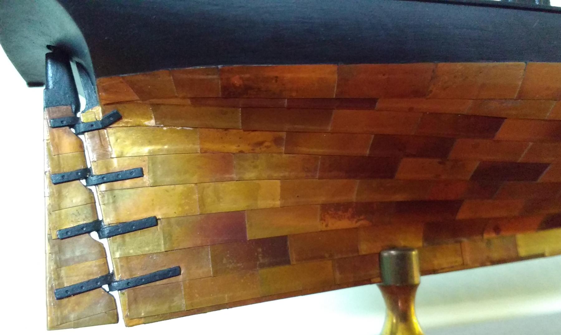
This is the process of making the heat treated plates for the Taney by Charles Gravallese. SHOP 03 COPPER PLATING The process begins with copper foil sheets 2 or 3 /1000" thick. To make realistic looking plates, the shiny uniformity of the copper must be destroyed. Holding the sheet with pliers, pass it through the flame of a gas torch and you will see that the copper begins to discolor. The longer you hold it there, the greater the discoloration. You will also see that it takes on a variety of other colors in random patterns. Work on only a small portion of the copper sheet at one time. After passing it through the flame, plunge it into a bath of cold water; this will add coloration. Don't worry about small droplets of water that may be on the surface of the plate when you put it back through the flame, they also add to the effect. Continue this process of heating and cooling until the entire sheet has been treated and it looks real ugly; that's when it’s done and ready for cutting. Before beginning the cutting operation, the copper sheets must be flattened and all wrinkles smoothed out. For smoothing, and strip prior to cutting I like to work on a clean flat surface like a green cutting pad. Smoothing is achieved by simply burnishing down the sheets with a piece of balsa wood. Along one edge of the sheet, gently tick off a series of marks to indicate the width of each plate as determined from the plans, (copper plates were normally about 2’ x 4’so you will have work calculate the model size based on the scale of the model. If the model is 1/8” to the foot, plates should be 1/4” X 1/2”. Repeat this same series of tick marks along the opposite edge of the sheet. To cut strips to the width of the plates, lay a straight edge on top of the copper sheet, connecting tick marks at each end. While firmly holding down the straight edge with one hand, draw the razor along the straight edge producing a cleanly cut strip. Repeat this process until all the strips have been cut. Upon examination of the strips you will notice that the cutting may have left a slight burr on the bottom edge of each one. These burrs should be flattened out before going on to slice them into plates. Burnishing gently with the balsa wood does the job. Next, the strips are cut into individual plates. Begin with a piece of 3/4" plywood 10" long by 3" wide as a work surface. This plywood should be flat and very straight along its top edge. Two or three inches in from the far right hand corner drop a sharp pencil line perpendicular to the top edge. Then draw a second perpendicular parallel to the first line and 1/2" to the left of it. (If you are left handed, these steps can easily be applied to work as well from the upper left hand corner of the plywood.) Place a small 4" adjustable square on the top edge of the plywood so that the leg of the square lies on top of the second perpendicular line leaving the first, right‑most line still visible. Take a strip of copper material and slip it under the square, making sure that: 1. The square is snug against the top of the board. 2. The copper strip is snug against base of the square at the top of the board. 3. The copper strip extends beyond the leg of the square and just touches the right‑most pencil line. Then it’s just a matter of pressing down on the square enough to keep the copper strip still while slicing off a plate with a single edge razor. Because the plates were sliced off while lying on a relatively soft surface, there is another burr to eliminate. Actually two burrs, one at each end of each plate. I did this working on top of a piece of plate glass. Using my balsa wood burnisher, I flattened out each and every plate. The bottom of the hull must be prepared and by this time you must also have decided on the arrangement of strakes and belts. The hull should be clean and sanded smooth with the water line already marked off. I did not use any sanding sealer in the are where the plates are to be placed. If you haven't already, devise a way to mount the hull upside down in your vice so that you will have two hands free to work on plating. This technique, by the way, can work just as well on planked hulls as it does on solid hulls. Take a dozen or so plates and drop them in small bottle of acetone. Close the bottle and set them aside for a while. The acetone will help clean up any residue on the plates. My preference for contact cement is solvent based and not water based. I have never had good experiences with water based contact cement. The contact cement must be thinned in small batches using a small glass bottle. In a clean 1 or 2 ounce glass bottle, pour a little bit of the contact cement. Add thinner to this a little at a time stirring until the cement is creamy and no longer stringy when you remove the mixing stick. With a disposable #1 paint brush, lay a thin coat of cement over the entire sternpost and keel, but not up the stem post. The stem will be coated later. In one of my earlier experiments I tried using un-thinned contact cement but this resulted in a globby surface which showed up as bumps in the plates after they were pressed into place. From time to time as work progresses, you will want to discard the cement in the mixing bottle, clean the bottle with thinner, and mix up a fresh batch of cement. While waiting for the first coat of cement to dry, remove the plates from the bottle of acetone and pat them dry with paper toweling. At this time you should drop another bunch of plates into the bottle of acetone and close it up. Take a piece of two sided tape about 6" long and press it down onto a scrap of basswood about 8" long and 1" x 1" square. Press the tape down firmly, rubbing your fingers across it until most of the stickiness is gone and the surface feels only slightly tacky. Gently press each cleaned plate to the edge of the tape strip so that half the plate is on the tape and half is extending over the edge. Using the low cost brushes, apply a thinned coat of contact cement to each plate. If the cement is properly thinned, it should flow right on, no dragging and no globs. At this time apply a second coat of cement to the sternpost and keel. After about 5- 10 minutes, the first coat of cement on the plates should be dry and the second coat can be applied. Allow this to dry another five minutes. Very gently remove a plate from the adhesive strip. The cement should not stick to your fingers, if it does, you have not allowed enough drying time. Beginning at the very end of the keel, carefully eyeball the plate over the bottom of the keel so that the keel passes as closely as possible through the center of the plate lengthwise. Before touching the plate to the keel, make sure that you are leaving about half of it to overhang the after part of the keel, over the sternpost. Slowly lower the plate being careful to keep it centered over the keel. I found that when first setting a plate in place it should be set down ever so gently so that the contact cement does not grab fast. This way, you will still be able to make positioning adjustments after the plate is on the surface. When satisfied with its alignment press down on top of the plate to secure it. Then carefully form a clean bend in the plate over the heel of the keel, up the sternpost. Using a single edge razor, cut along the bend in the plate, back to the keel ‑ sternpost junction. Now bend the resulting vertical flaps which overhang the sternpost, into position toward the bow. Apply a small dab of contact cement to the face of these flaps, and then press down on the horizontal flaps which overhang the keel. Note: I use a very fine jewelers tweezers to handle individual plates. Apply a small dab of cement on the top of the forward end of the corner plate you just installed. Let this set up for a few minutes and then take another plate from the adhesive strip and follow the same alignment procedure in positioning it over the keel making sure that the after end of the new plate overlaps the forward end of the plate already attached by about 1/32". Press the plate into place on the upper surface of the keel and then firmly bend the side flaps downward so that they form a neat 90 degree angle around the edge of the keel. Continue this process up to the place on the keel where the stem post begins to turn up toward the water line. Return to the sternpost and lay the next strake which will slightly overlap the previous strake also by about 1/32”. Begin by applying a coat or two of thinned contact cement to the area of the previous strake which will be overlapped by the new strake. Allow this to dry for a few minutes. Don't forget to keep extending the cement coated area up the sides of the hull a little at a time as you go along from one strake to the next. I used masking tape to keep the cement area to just one strake width. I suggest coating only a small area of the hull at one time because at the end of each plating session you will want to remove the cement from those parts of the hull which have not yet been plated. Center a plate over the backside of the sternpost and press it into place. carefully wrap it around the post toward the bow. Now you can proceed to lay on the second strake of plates from stern to bow, aligning them so that short vertical seems are offset and fall on the middle of the plate in the strake you are overlapping. In other words, the applied plates should begin to resemble a brick wall. Repeat this process for both the port and starboard sides before proceeding to the next strake. Before laying on the third strake and for all following strakes, a little measuring is required to ensure that each strake is even as you proceed up the sides of the hull. Beginning at the stern, from the top edge of a plate, tick off a mark at 7/32" onto the bare wood of the hull. Make a series of these tick marks from stern to bow, the more, the better. Then connect them with a flexible batten and draw a light pencil line through the dots. Make sure the area between the last row of plates and this line is covered with contact cement and you can now apply the third and all subsequent strakes. In positioning a plate, align it so that the long horizontal edge is right on the pencil line you drew, and the short vertical edge overlaps its neighboring plate to the rear. Eyeball each strake when completed to make sure rows are progressing equally up each side of the hull. As each strake comes to its termination point in the bow area, bring the plates right up to the stem post, then cover the exposed forward ends with one plate by wrapping it around the stem post. Never go ahead any rows when working up the stem post; remember, all the vertical overlaps must be toward the stern. When cleaning up unused or old cement from the surface of the bare hull or the plated surface, use a compatible thinner, not acetone. Allow a few days drying time before cleaning excess glue. Acetone will break down the cement along the edges of the plates, and thus the weakened plate edges will be more easily ripped up at corners and edges. When you make a mistake in placing a plate, don't try to salvage it. Throw it away, repair the damaged cement area with a cotton swab dipped in thinner, apply new cement, and put down another plate. In order to reduce the number of gluing brushes used, in between coats I rinsed and stored my brushes in a bottle of thinner. TOOLS AND MATERIALS 2 or 3 /1000" copper sheet 6" x 12" cotton swabs inexpensive #1 brushes balsa burnishing sticks 1 and 2 oz. mixing bottles two faced tape mixing sticks paper towels & rags acetone single edge razors contact cement & thinner small adj. square
-
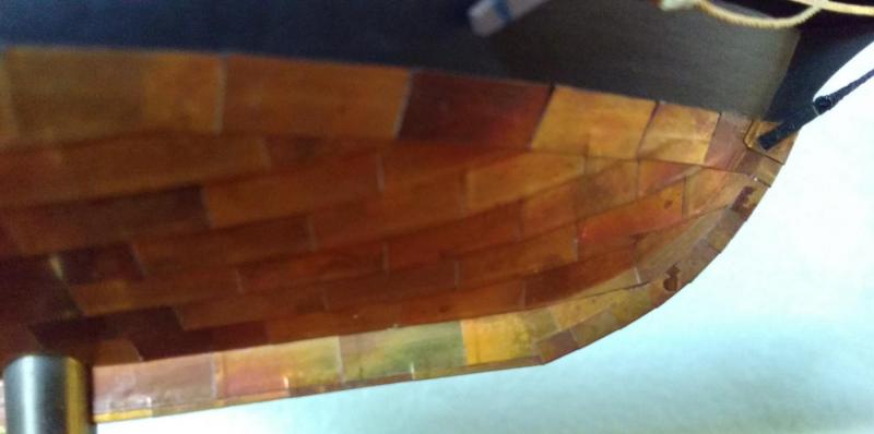
These pictures are of the Revenue Cutter Taney at 1/8th scale. The model is by Charles Gravallese. I will post more detail on the process later. He manufactured each copper plate from sheet copper. Prior to cutting strips to make the plates he heat treated the copper sheet. That is how he obtained the variegated color.
-
All I have reviewed the replies and will recap here. 1. 1/64 and smaller may not require the nail pattern, no matter the size of the model. Although some do try it. 2. Copper plates made from copper tape applied over a varnished hull work very well. 3. The problem with the nail pattern is it will be nearly impossible to replicate it to scale. It will appear bumpy and too busy. 4. This applies to the thickness of the plate as well. Some suggested gold leaf type of products and thinner stuff than copper tape. 5. Making a nail pattern stamp to indent the copper plate seems to be the preferred way to create the nail pattern. However dress maker's wheel was used by one and ponce wheels I know will do the trick as well. 6. Shiny copper is not authentic and neither is copper of all one color from keel to water line. In actual ships there will be a color variation. Some sort of green, not copper will be required to make it authentic. 7. Chemical treatments are necessary to change the color of the plates. The first suggestion was salt and vinegar. However there are links for how to achieve different colors in post number 19 above. There was a discussion of using vinegar on copper 8. Urine was used by at least one of our group to achieve a brownish type of color. It was applied after the copper was on the model. 9. Nearly the last contribution was posted and translated from a German source who advised that as the copper ages it actually goes pink in parts. I will continue to edit this post at the suggestion of contributors. I have not had the time to search MSW for build logs to copy some of the posts here. I may in the future. Phil
-
Joe That looks real nice. The the penny brown color is great. Just looked at you build log. Think about posting the before treatment pictures to the reply above. Its a big contrast. Phil
-
Brian asked some questions about standards of copper plating. Did a little research and have the following to offer. Brian Lavery in The Arming and Fitting of English Ships of War devotes chapter 11 to copper sheathing. He provides the history and methods and techniques. He states the plates were 4 feet long and 14 inches wide and that this size became standard very early in the process. He reports that three thicknesses (gauges) became standard by 1779. They were 22oz, 28oz and 32oz per square foot. "They were distributed about the ship according to the wear they were likely to encounter. The thickest were in the bows, the medium ones just behind the bows, and the rest of the ship was covered in the thinnest type." Peter Goodwin in English Man of War devotes Chapter 10 to Hull Protection. He provides a few diagrams. He states the nails were spaced about 1 1/4 inches apart. He gives a little larger dimension of the plate at 4 feet long and 1foot 3 inches wide. He also discusses the weight added to the ship. In the case of a 74 gun ship, the 3300 plates needed added13 tons, plus the nails. I believe my copy of the book contains a typo or editing error as he advises than 16 nails were used to secure each plate. I think it would be closer to 160 nails if they are only 1 1/4 inches apart. Phil
-
GemmaJF Is your Bounty one of the kits? If so which kit and at what scale. Perhaps there are examples on MSW we can look at. Phil
-
Mark Thanks for your input and perhaps a rule of thumb. I make the next comments only to continue the academic discussion. First make sure I have understood your comment. "To my eye, on anything 1:64 or smaller, treenails and plating nails look out of place." I interpret this to be inclusive of 1:64 scale models. The first example to come to mind is the Model Ship Ways Constitution at 1:76 scale. I consider this kit to be one of the larger size of models. All examples of the the completed model that I have seen include the nail pattern. Another example is Caldercraft's Agamemnon at 1:64 scale. A large model. If we agree that we can not really put in all the required nail holes, is there a lesser pattern that is acceptable and gives the proper representation of of the nail pattern? An intentional compromise due to scale. Are there any photos on MSW with these large models with no nail patterns? I look forward to the continued discussion. Phil
-
John Thanks for the link to your Kate Corey Build. That build log also had pictures of your Eagle. On Kate Corey no nail pattern. On Your Eagle it looks like you put nail pattern on the edges only. Could you remind us of the scale of Kate Cory and Identify the scale and maker of the Eagle model? Also, when you get a chance could you post more photo's of both hulls and identify what we are looking at. Thanks again. Phil
-
I have spent my morning reviewing the content on Model Ship World that concerns copper plating the hull. I have reviewed the threads on materials(tape, individual plates etc.) and the information on the processes involved, including the available PDF articles on the topic. Almost all of it concentrates on getting the job done with use of copper tape, ponce wheels, and individual plates. Very little of it even hints at what may be appropriate for the scale (other than the size of the copper plate) and subject being modeled. Here are some statements based on some conclusions I have made to demonstrate what I mean. A). Consistently good results are achieved in very large models. These models probably require individual plates that are fully scored for the the nail pattern. Because it is a large model, the scale of the subject is not much of a concern here. At the scales the majority of the large models are made, an exact and historically accurate nail pattern(I mean the number of nails here) may not be necessary for the model. In these models the copper nor the nail pattern overwhelm the model. On December 30, 2016 Chuck posted in thread the "Best copper plates?" what may be the gold standard for copper plating. The copper on the hull gives it a very textured look. I could not figure out how to copy it here, so if someone would copy it here I would appreciate it. B In most models, and at most scales the absolute historically accurate nail pattern will not be necessary and in fact may overwhelm the model presented if attempted. I think this is especially true in smaller subjects NO MATTER THE SCALE. Your eye is distracted from the overall model because it is drawn to the shiny and pronounced pimply texture of the hull. I think manufactured plates on smaller subjects may be the worst offenders here. C) The bigger the model the better manufactured plates will look. The smaller the model the appearance degrades the model EVEN IF THE SCALE is correct. D). Copper Tape may be a better product to copper smaller hulls. You are able to control all aspects of the plate from scaling it properly to deciding on a nail pattern that presents best. This assumes that it is impossible to duplicate historical accuracy in the small subject or is undesirable to do so. E). At what size subject or scale is it best to copper the hull, show the plates but not put a nail pattern on it? As an example, the Model Ship Ways Phantom Pilot boat, is a small model but at 1/8th scale may make individual plates possible and desirable. Is there a consensus when the scale of the subject is small enough that nail patterns or copper plates are no longer required and the model is not deficient for the lack of these details? F). I have not located an example where the plates are represented but the nail pattern is absent. Please post any examples you are aware of. G). Shiny vs. Weathered. We all now the facts. The copper was not likely supper shiny when it was put on the ship in the first place and if it was it was copper green in a very short time. Yet the majority of modeler's present the shiny copper. Why? Because is looks nice and presents the subject in the best light. In clipper ships especially I think it better represents the race horse quality of the subject. I make this point to demonstrate that we spend a lot of time on individual plates and nail patterns and have already given up historical accuracy with shiny copper. H). A Practical exercise and example. I will soon copper the hull of my AL kit of Dallas. It is at the European scale at 1/50, close enough to 1/48 so as not to have any scaling problems with the making of individual plates or scoring copper tape strips. I must decide if I will put in nail patterns. I think that at this size model (the hull is more than 17" long) I must make individual plates and overlap them if I do not put a nail pattern in them. If I decide that I will use a nail pattern I will use copper tape strips. I am looking for examples of a hull with copper plates without a nail pattern and would appreciate a discussion and examples that demonstrate the points I made above. When do they look good and when do they look bad? Phil Roach
-
Adding sails to Mayflower - MS kit
roach101761 replied to dchrismiller's topic in Masting, rigging and sails
Chris I have just looked at a few books on my shelf. William Baker's book, "The Mayflower and other Colonial Vessels" contains a sail plan. Although I do not know where to get the plans, I am sure they are available from someone. Perhaps someone reading this knows. Also, David Antscherl published an Article in the Vol. 58, No. 4 Winter 2013 issue of the Nautical Research Journal regarding his new interpretation of a 1600 merchantman(his idea of what the Mayflower may have looked like). He had no sail plan then. Also I looked at Brian Lavery's book the Susan Constant in the Anatomy of the Ship Series. The Mayflower is accepted to be 180 tons. Although the Susan Constant is about 100 tons, Lavery's book may be a good place to start in order to develop sails and a sail plan for the Mayflower. Like all the Anatomy books, Lavery has drawn all the Susan Constant's sails. A Copier works wonders when you need to scale something up or down. Phil Roach Director NRG President Ship Modeler's Guild, Southwest Florida -
Seeking information on determining load waterline
roach101761 replied to trippwj's topic in Nautical/Naval History
Wayne Pulled down my copy of Dean's Doctrine of Naval Architecture, 1670 edited by Brian Lavery copyright 1981,Conway Maritime Press. I do not know why I did not pull it down a couple of weeks ago. I guess I presumed you had reviewed it as you mention Dean above, or perhaps I just forgot I had it. Hard to keep track of my books. I pulled it down for another purpose today. From reading above you may be reading from a copy of the actual manuscript. I have only read parts of it today but Lavery's introduction explains exactly what the work consists of and why it was written in the first place. There is a whole section on "The water-line or greatest depth of water the ship must draw, completely gunned, rigged, victualled,and stored". Through this section and the sections that follow, it is apparent that he is aware, and has the ability to design a ship which will float on the load water line he designed and fit for its intended purpose. He explains how he does it but does not give the math. It kind of reads like he backed his way into the result that proper math would have calculated. As an example: You have a pile of 49 objects and you desire to know how many separate equal piles of objects you can make. Rather than solve with math, you keep physically dividing the pile until you get to 7 piles of 7 objects each. As to your earlier post in which you were looking for contracts for ships prior to 1750, Lavery's book contains in its appendix the specifications of a third rate of 1666 and states that the original before it was amended, was for the Speaker of 1649(renamed Mary in 1660) The designer of the ship was Christopher Pett who drew up the first version of the specification. Alas it is only a contract specification for a builder. It does not mention LOL. This seems logical to me because the builder would not be responsible for its design, only its construction pursuant to the contract. Phil -
Dave Are you looking for History books on the topic or model ship building books? I have a book in my office concerning only Baltimore privateers. Can not remember the name or would direct it to you now. I will however post it on Monday, unless someone here bets me to it. This book give a history of Baltimore privateers and goes deep in to the finances of the privateer venture. Good book, lots of detail. Phil
-
Seeking information on determining load waterline
roach101761 replied to trippwj's topic in Nautical/Naval History
Michael I have looked at the plan above and I can not see where the load water line is marked "load water line" or "LWL". Also, on your copy of the plan, is there a date of the plan? I am not referring to the title of the plan. Phil -
Wayne I too am a primary source guy. Why would I want someone else to read it and interpret it for me when I can look myself with a little work. Phil