
HOLIDAY DONATION DRIVE - SUPPORT MSW - DO YOUR PART TO KEEP THIS GREAT FORUM GOING! (Only 72 donations so far out of 49,000 members - Can we at least get 100? C'mon guys!)
×


roach101761
-
Posts
204 -
Joined
-
Last visited
Content Type
Profiles
Forums
Gallery
Events
Everything posted by roach101761
-
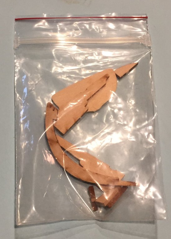
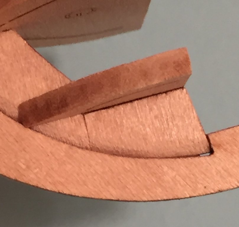
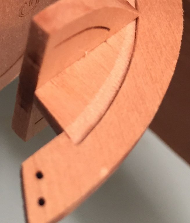
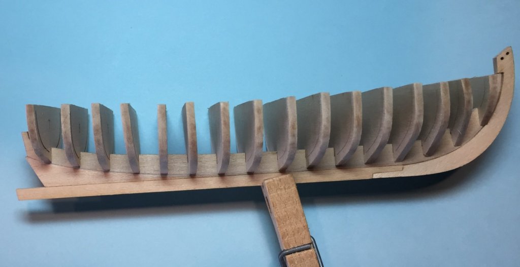
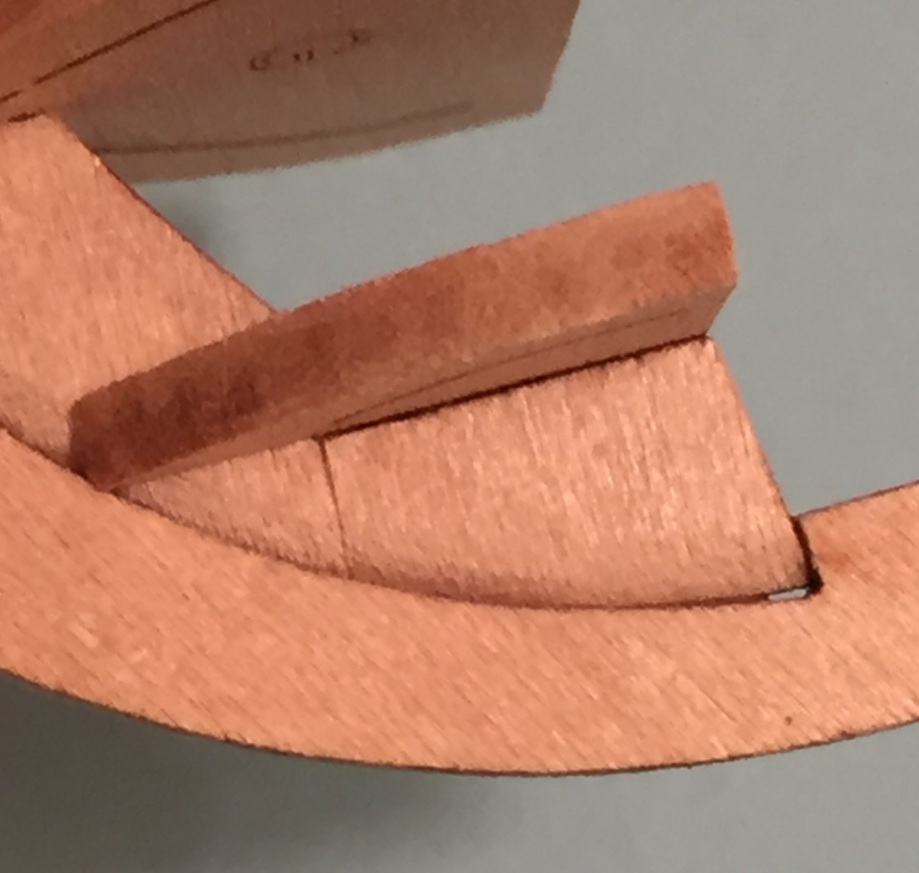
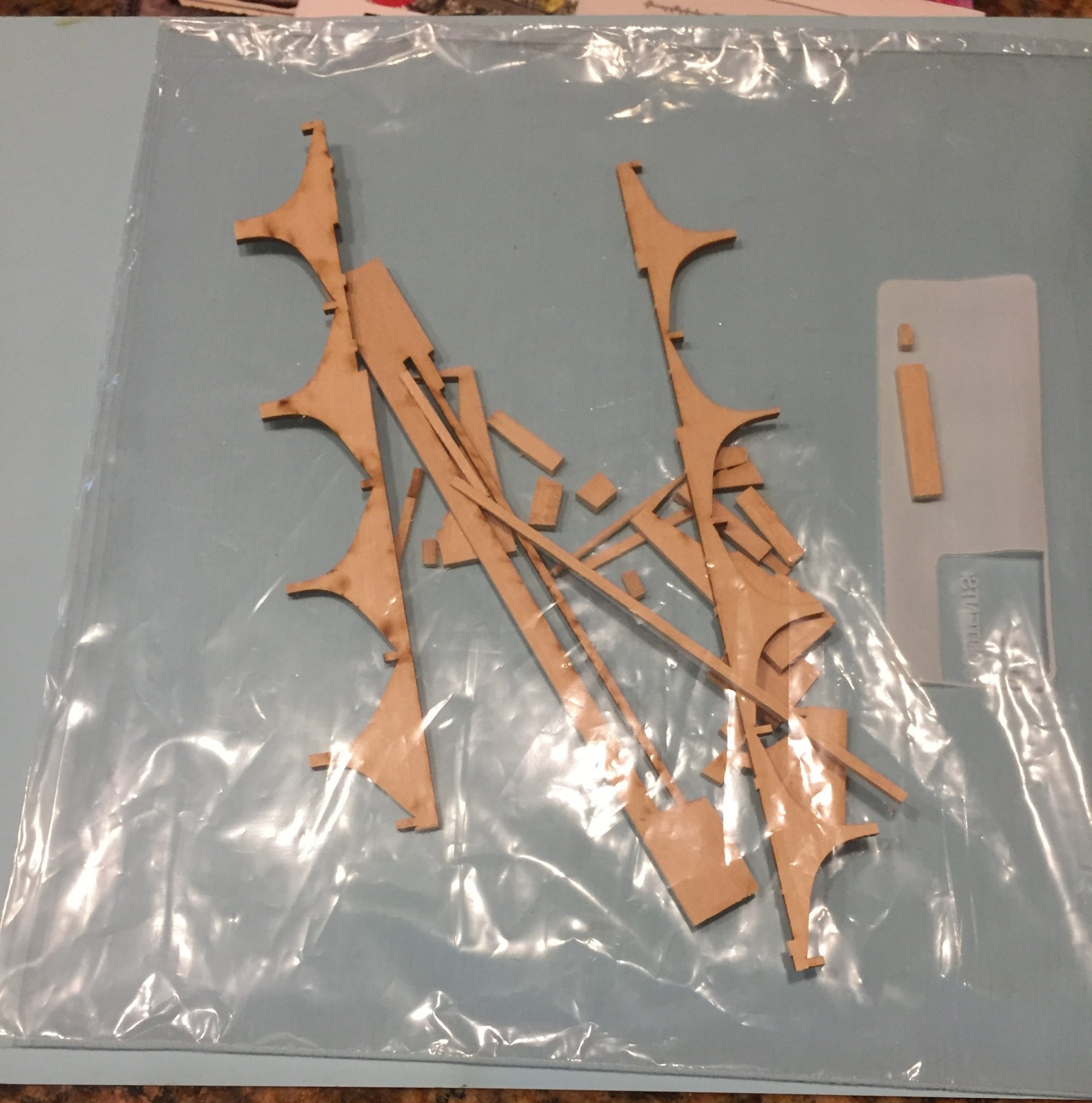
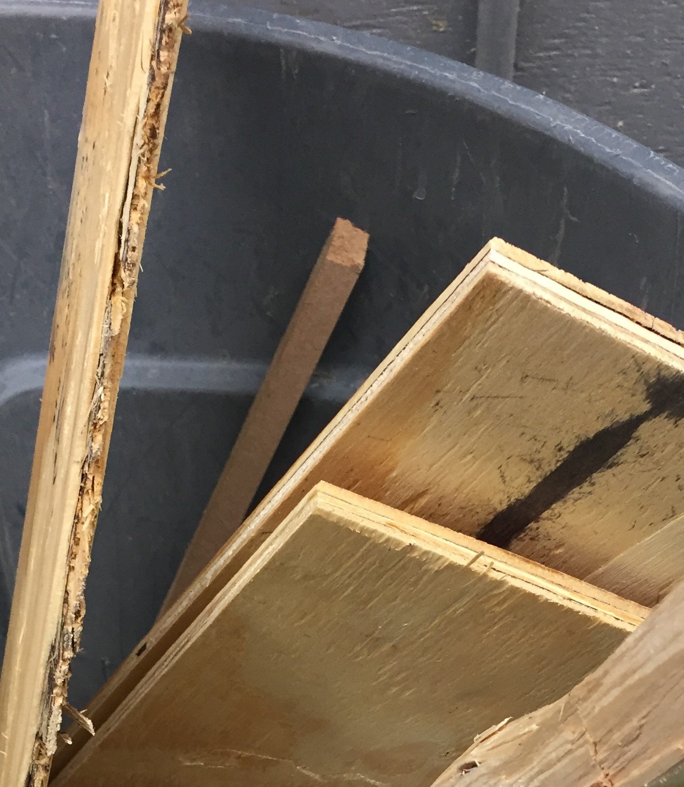
REPAIR OF BROKEN BOW ON FALSE KEEL--Going through the posts and realized that I did not include a description on how I repaired the false keel after I broke off the bow piece. I decided not to repair it immediately because I was still working on the false keel and did not want to break it again. Here is the bow before the repair. Basic modeling tip Most important thing to remember is not to lose the broken part. When I punched out the parts from Sheet A and Sheet B I placed them in a small plastic bag for safe keeping. This included the other little parts such as the stern post and bow blocks. In ship modeling little parts are like socks in the dryer. They travel and disappear. Its much worse than you can imagine because they are better than Houdini. One minute you will have the part in your hand while working on it and it will disappear from your hand, NEVER to be seen again. The reaming parts are pretty lonely in the the bag these days but they are not going anywhere. I thought about how to re-attach this little piece. Perhaps the bow blocks could be installed early? After dry fitting them I determined they would offer little support and probably get in the way when I shaped the part for the rabbet. I thought about epoxy or super glue(CA) but decided that would violate my rule about tools and materials. These things cost money, and compared to the cost of this kit they actually cost a lot of money. In the end I decided to go with the glue I had chosen and use the Elmer's white glue. I applied the little glue that was necessary, correctly lined up(always dry fit before you apply glue) the two pieces and pressed the parts together on a flat surface using my fingers to hold the parts together until they set. This may take a couple of minutes. Clean up the glue on both sides and leave it alone for at least 24 hours. Would this repaired part stand up to shaping? I used the building board and my files to create the false rabbet in this end of the bow while holding it down with lots of finger pressure and very gently shaped the rabbet. I had previously shaped the rabbet to the end of the larger false keel which meant there was less bonding space, but on the other hand I had a bevel to file too for a guide. Here is a photo of the repaired Starboard bow. Here is a picture of the repaired Port bow. Looks better on the port side. When glued up to the stem, the stem adds more support. When the bow blocks are attached they also will provide more support. I did not glue the bulk head to the false keel on the forward portion of the bulkhead. One more word on keeping track of small parts. Here are the remains of sheet B. We will be using this wood to make spacers and supports between bulkheads and for a fixture to mount the model to plank it.
.thumb.JPG.ff06b9649aa82c99b8bf9c627736fd31.JPG)

-
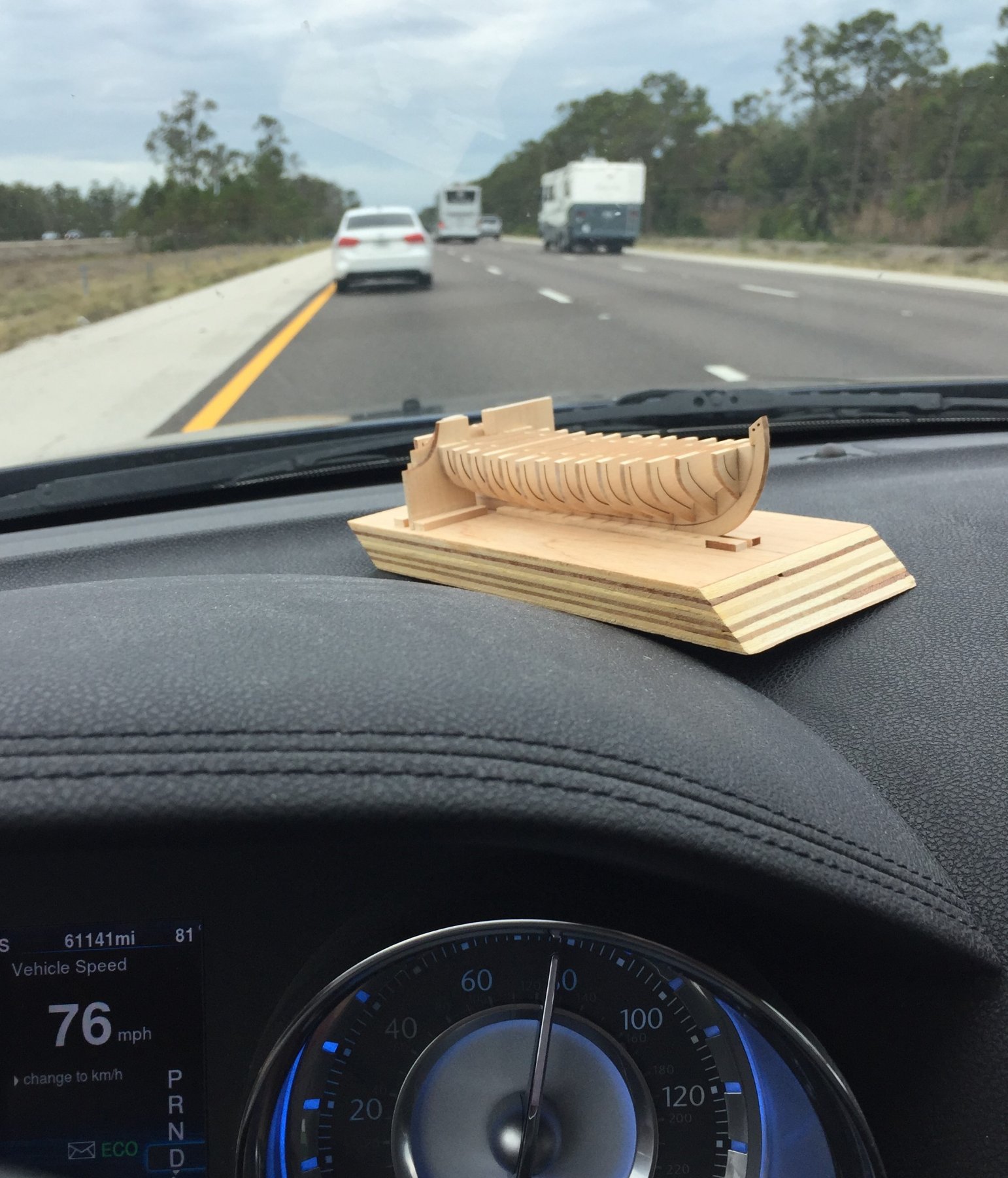
My club meeting was this last Saturday. We always encourage everyone to bring in their model. This can be very difficult sometimes, especially with works in progress. Its hard to keep the model secure in the car. A huge advantage to this little boat is that it is easy to transport. It can ride anywhere and even get a good look at the world. Before I get any comments about the indicators on my Dash, that is slow for me on I-75.

-
Building board--conclusion I have my building board now that will enable me to provide the precision to the build that is necessary to fine craftsmanship and a I am ready to start. Right? NO! As I mentioned above I encountered a huge problem in setting up the two segments of the wall. BEFORE I set the wall in place I put both pieces next to what I knew to be a flat and square surface and discovered that the two portions of the wall had DIFFERENT THICKNESSES!!!! How did that happen? After all sheet A and Sheet B are 3/32nds thick. NO THEY ARE NOT!!! I carefully looked at the remains of sheet A and Sheet B. In my kit, Sheet A was visibly thicker than Sheet B. Not only that, both Sheet A and Sheet B were not uniform in thickness from one end to the other. DO NOT COMPLAIN ABOUT THE DESIGNER OR MANUFACTURER. Perhaps I should remind all of you that we are using this wood and creating things not intended by the manufacturer or the designer. All was not not lost. After all I own sandpaper and a sanding block. This also goes to show that one half of one millimeter and 1/64th of an inch is a HUGE DISTANCE in ship modeling. I sanded the part down to the correct thickness. Even so small a distance was not fast. It took a while. You must position the part one way, take six strokes, reverse the part on one axis, take six more strokes, reverse the part on the other axis and take six more strokes, reverse again and repeat. You take constant measurements during this process to make sure the wall segments are the same thickness. BASIC MODELING SKILL TIP You take limited strokes and turn over the work and reverse the part to insure that finger pressure does not cause the part to be thicker at one place and thinner at another. Now the wall segments are the same thickness and now we are ready to proceed. Most but not all spaces between the bulkhead faces are 9/32nds. The most obvious departure is bulkhead 0 (zero) and Bulkhead A. It is a wide space and is where the windless will be installed. My idea was that I could position bulk head 0 and #1 on each side of the wall and set up two bulkheads at once, saving lots of time. WRONG!!! THIS BRIGHT IDEA WAS A TOTAL FAIL!!! For two reasons. 1. The wall segments were positioned above the bulkheads so I could not see the tops of the bulkhead to insure they were consistent with each other or the next pair. This was in spite of my careful measurements of the height of each of the bulkheads. 2. The plans show the bulkhead faces 9/32nds apart, but a human hand with a file can not do this. Filing the char from the slots by hand is not real precise. You can get close, but 1/64th of an inch is not close enough in ship modeling. Ship modeling is not horseshoes or a hand grenade. I could have filed some more in the slots in the false keel but this would have made each one wider to adjust the faces between bulkheads and therefore a loose fit for the bulkhead that would have sacrificed the fit and bond of the bulkhead and ultimately the frame to the false keel. Therefore I scraped my idea of setting up two frames at once. I did proceed for awhile before I noticed the frames did not line up properly. Also I will add a third issue. 3. The support rails should go end to end on the board. This little and light hull twists a lot with only slight pressure. End to end support rails would have gone a long way to rectify this situation. I did get the job done and overall I am happy with my building board and the stationary gantry that the the keel passes through. Next, setting up the bulkheads on the keel assembly. Sorry, no pictures on this post.
-
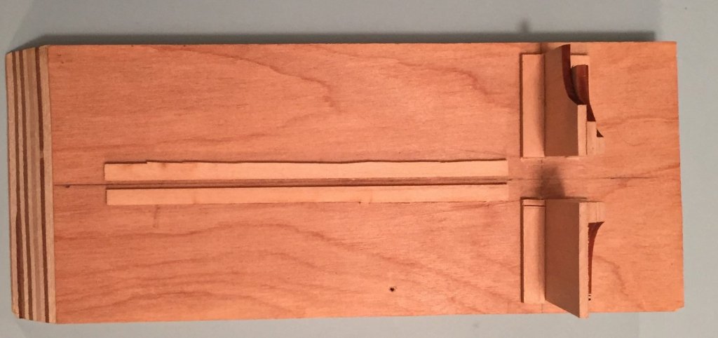
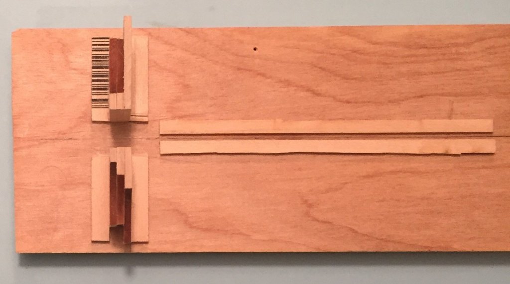
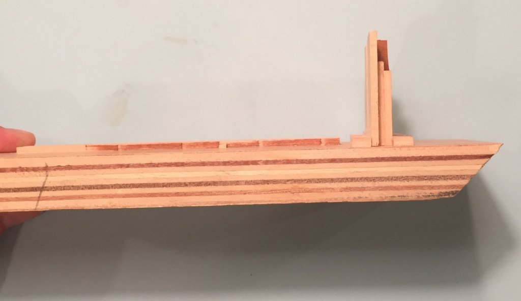
Building board cont. Gantry Wall and completed building board. In order to better explain I thought I should show you pictures of the completed building board with stationary gantry in place. The first two photo's below are taken from above. They show clearly the stacked segments set on their edge forming the pass through wall. It is necessary to set them perpendicular to the center line drawn on the board for the keel. Because the wood was not square I could not use a square. To make the line I used a small protractor to make sure the line was perpendicular. It was one laying around the house from my kid's school days. Please remember I was still working this stuff out as I went along. I believe the correct order would have been to start with a slightly longer board and then: 1. Draw the line for the keel. 2. Draw the perpendicular line for the pass through wall. 3. Erect the Wall on the Building board. 4. Then cut out the support piece for the wall so that the keel supports will pass through it. 5. Then place the keel supports end to end. All photos above show the support pieces for the wall. I broke one of my rules here. That is a piece of basswood I had at home. The scrap in the kit did not provide what I needed. I needed a piece wider and bit thicker to provide adequate support for the wall panels and I needed it to be almost 8 inches in length so it would fit across the board twice. It also could not be higher than the lowest bulk head on the boat or it would interfere and block the bulkhead from mating with the wall in order to glue it up. My part was 8/32nds (1/4") wide and 4/32nds (1/8") thick. Please make sure you read the end of this series of posts on the building board. I ran into a two significant problems in setting the wall in place and in the actual use of the building board. Make sure the first support piece is straight on the perpendicular line and glue it down. You can then with your fingers wedge the wall panels with the other support and adjust the space between them for the keel to pass through. My gap is a 1/2". Mark the space and then apply the glue to the wall panels and place on the board. Work quickly, because the support piece is going up next. To make sure the the wall is at 90 degrees to the board you need a square or a square substitute. I used a Zona square three inch ruler but had available a plastic triangle square from that same school geometry kit. When the wall panels are in place, place the second support making sure that you do not alter the angle of the wall. Set the assembly aside to dry over night. The next post will be about issues I had setting the wall panels and about the actual use of the building board.
-
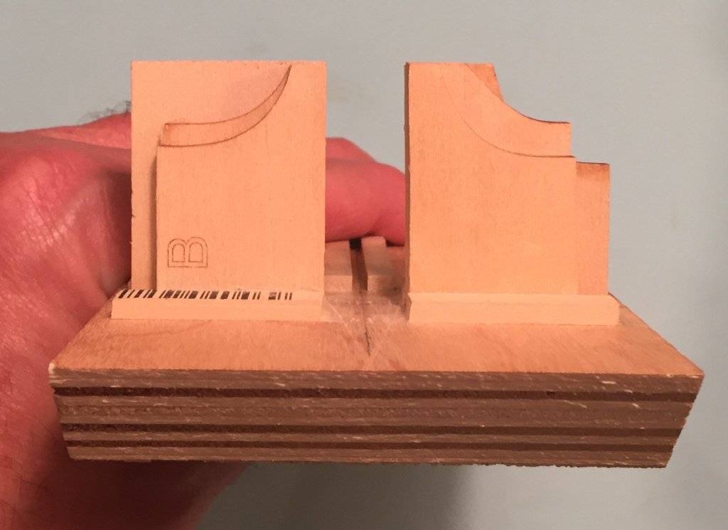
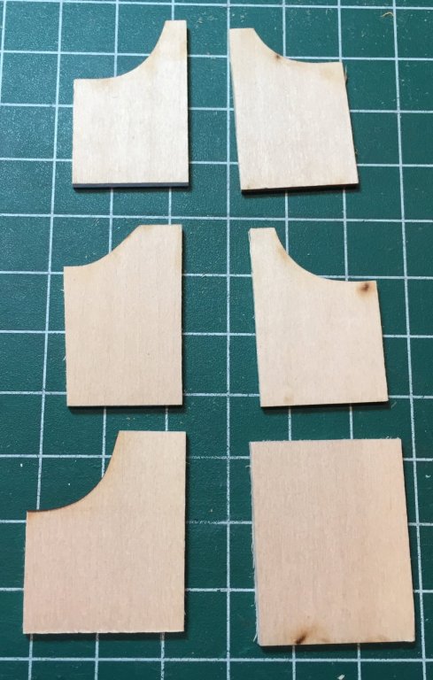
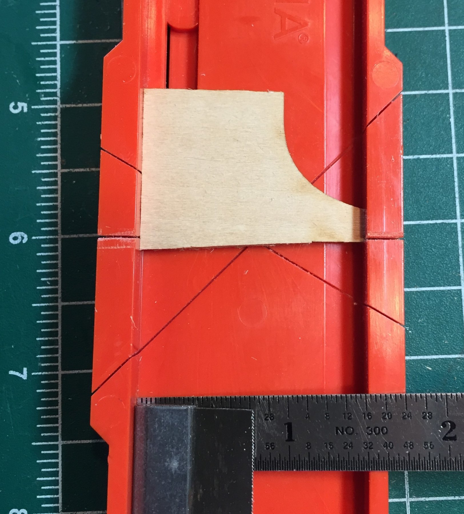
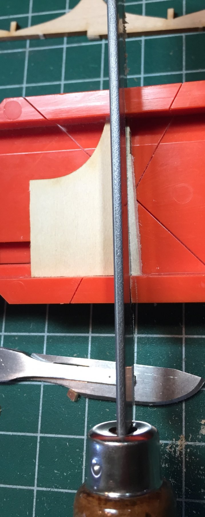
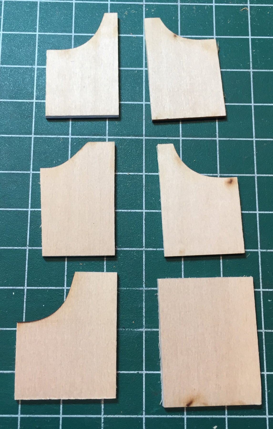
Building board cont. ---The Gantry Wall. If you look at the plans and measure you will note that most of the bulkhead faces are 9/32nds apart. WOW!!! That means that if I had a wall 9/32nds wide, that the keel but not the bulkheads passed through, I could line up, glue up, and clamp up two bulkheads at once. We already know that we have 2 sheets of 3/32nd basswood in the kit. I just need to stack three segments and glue them up. Which I did, twice. The photo's show the assemble process. I decided I needed the two large pieces from sheet A. Next, I squared up another edge in miter box. It will hold a part 1 1/2 inch so I cut them to these widths and then squared up the tall edge. One edge was already square because all six segments were on the end of sheets A and B. I then selected my six best, and selected the best fit for three each for the right and left portion of the wall. The key edge is the bottom edge. They must stay flat on the bottom when you glue them up. You will have two halves of the wall when done.


-
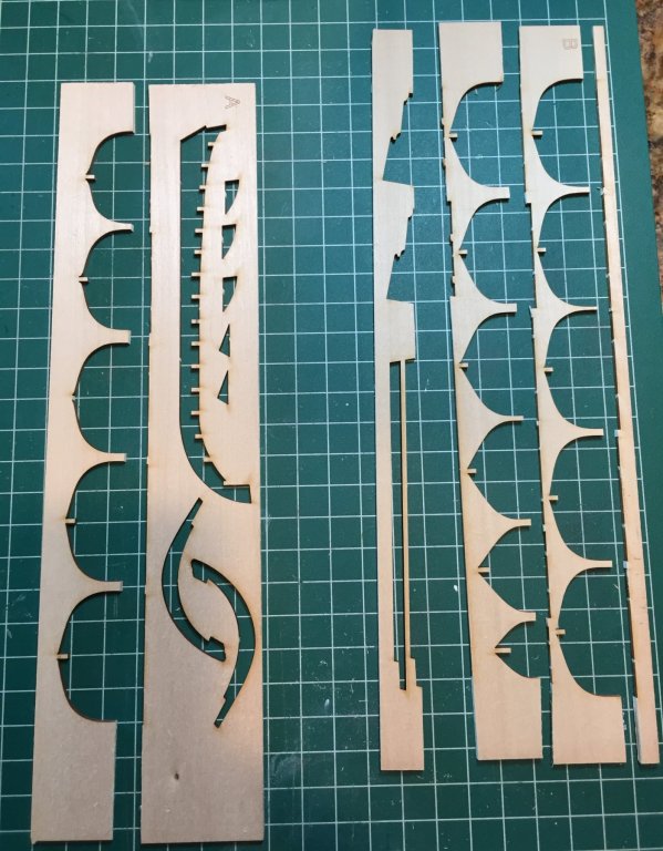
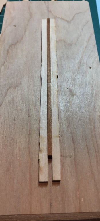
Building board cont. My board was not squared. However, I took my 6" machinist ruler and attempted to find the approximate middle of the piece. In this case it was about an 1' 5/8th in from the side. I placed a dot with my pencil. Two inches or so further up the board I did it again. I repeated the process until I got to the end. I then took my longer ruler and connected the dots. The line did not fall exactly on all the dots, but it was close and more importantly the line was straight. See the line in the photo above. That line is where the keel will go. Next I harvested wood from the 3/32nd sheets contained in the kit. This way, you do not need to buy more and the scrap wood in the kit is put to use. The next photos are a series showing how I cut up the scraps to get the lengths I wanted. The Sheets are labeled A and B. Note the long piece with the straight edge on sheet B. At this point I was also trying to conserve as much of the wood as possible Because I did not know, and still do not know what other uses the wood will serve. I also did not want to destroy the pattern for the false keel in case I had to make a new part. However, please remember that Model Shipways will replace parts. The below photo shows my continued cuts ant the new tools involved. A Miter box and my very fine Zona saw. I learned during this process that I have a dull saw and it is time to replace it. As you can see I am tying to locate the largest wood masses I will use these to build the solid Gantry wall that the keel will pass through when I attach each bulkhead to the keel. In the next photo the building board is on top of whats left of sheet B and the top edge of sheet B has be cut to serve as the support rails for the keel. You will note that on only one edge is straight. One will be reversed. No need to trim up the outside edge. Remember it is scrap, and later in the build you will remove the two rails and gantry to construct a stand to invert the model to hold it while you plank it. This will also provide practice for dissolving the white glue when you remove them. In the next photo I have attached the two rails that the keel will sit in as I attach the bulkheads. What I did was position the extra keel on the center of the line, and then wedged it between the two other pieces. I only glued one at a time. To position it with glue on one rail I held all three together to make sure the keel was centered. When it was initially set, I picked up the keel part and moved the other rail and then quickly removed the glue that squeezed out. I then repeated the procedure for the the other rail. I made a mistake here in using the spare keel that had not been sanded. When I put the Keel assembly into the slot it was not as tight as I expected because the keel assembly was sanded and the spare was not. I got buy with the bulkheads, but a beginner may not. Next I had to build and position the gantry wall. Two things I did not anticipate before I started working it out. First, the keel slot should have gone from one end of the board to the other and Second, I did not think that there was not sufficient space at either end to erect the gantry and have a useful enough landing or resting place for the keel on the other side. To correct the second problem I cut some of the rail at one of the ends and then soaked the part to removed with water and pried it up and off the board. Next, building the wall to pass the keel through.

.thumb.JPG.801e84ab34fccfddd06d47180a3ad709.JPG)
-
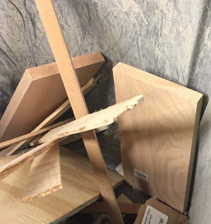
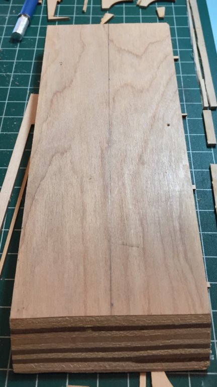
The building board. This will take me some time to describe. (I write almost as slow as a build a ship model) Therefore it will not be in one post, but in two or three. With the idea of a beginner in mind I stuck to my rules about hand tools and materials. Some tools you must have, but I have tried to keep them to a minimum. First the materials. You need a board. Here is a picture of mine again. It measures about 8" X 3 1/4". If I had to select again, I would make it longer by two or three inches, so that when the keel passes though the stationary gantry (I will explain below) it will be supported on the other side. I did not cut this material so it is not exactly squared. I went to home depot this weekend and took a look around for cheap building board material. Below are photo's of the trash bins at the radial saw and vertical saw cutting station. They are all end cuts or side cuts from the operation. The best part is that every thing in the two bins was free, because they consider it garbage. And for the very observant, those are two really nice pieces of red oak in the second bin. I left them where they lay.
.thumb.JPG.20ea5e467fa746e0339a0c9e3faed4b2.JPG)

-
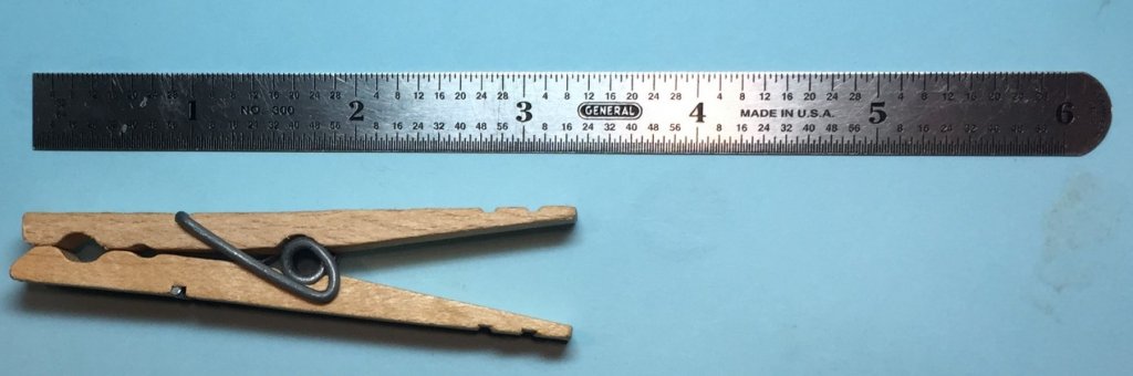
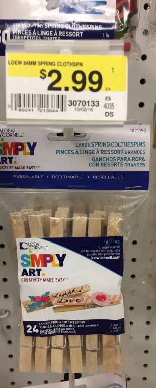
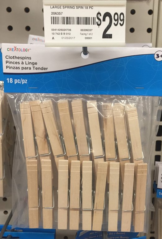
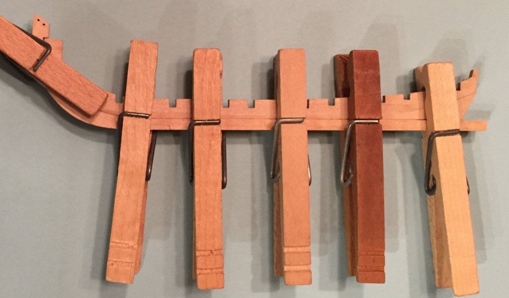
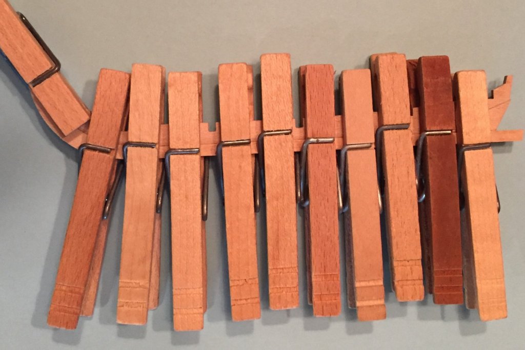
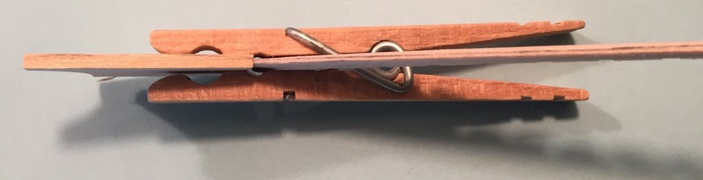
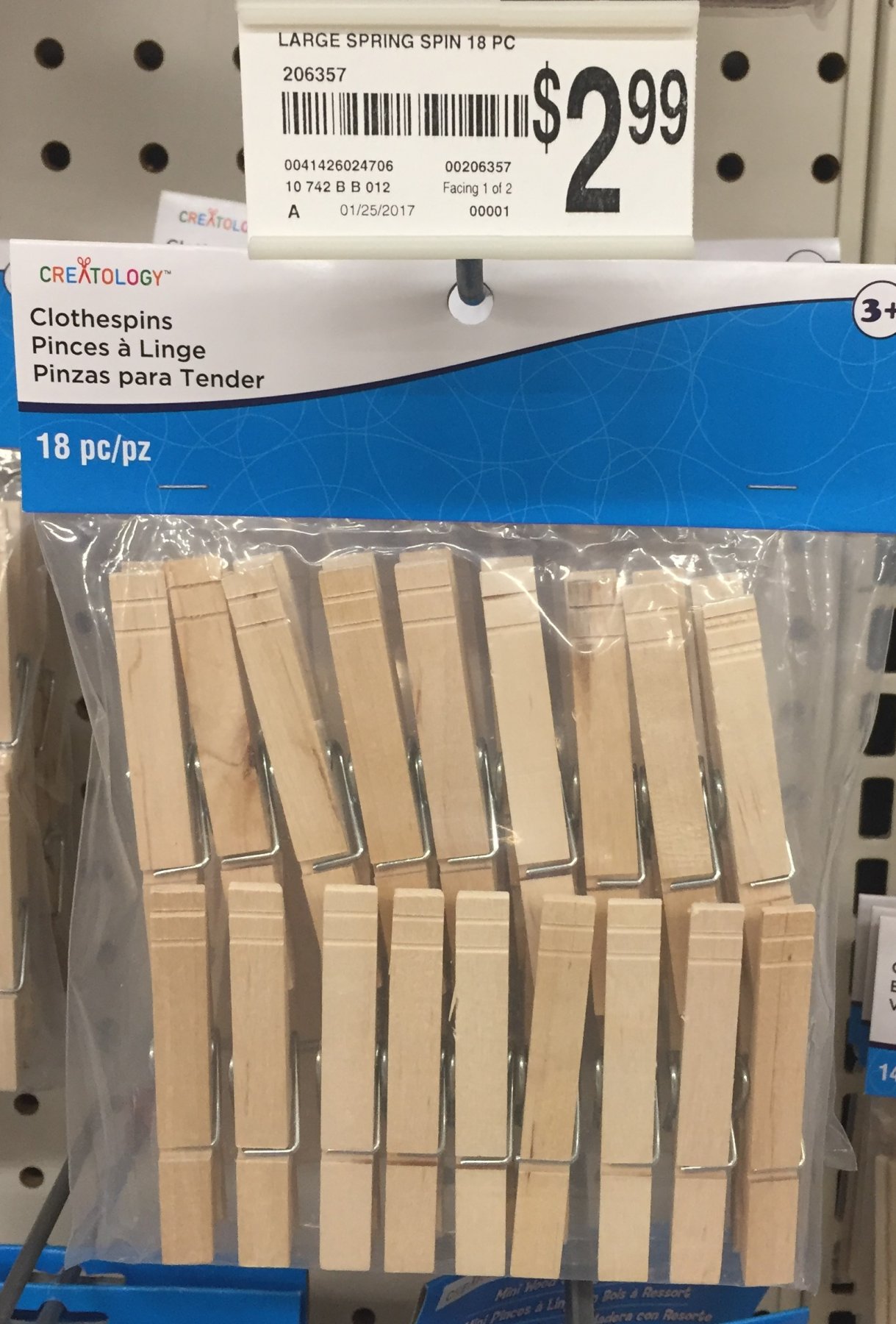
Tool update--the lowly clothespin You now must have noticed that the clothespin has now become a tool. Previously it was just holding parts so I could take pictures. Now it is the most utilitarian clamp you will ever have. Thus far I have only used one size, the large size, but I do anticipate that I will use smaller sizes in the future. Go to a craft store and buy some if you do not have any at home already. The photo's below are from Michael's and JoAnne's. The ones they sell are nice and unblemished with no chips or poor parts or wood quality. As if you need photos, but here they are.
-
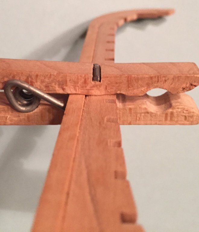
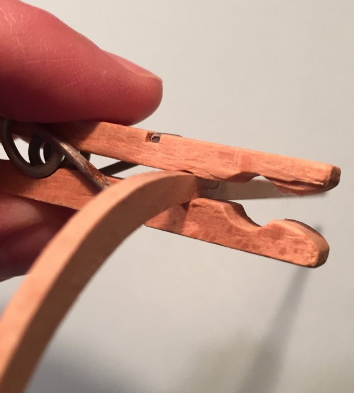
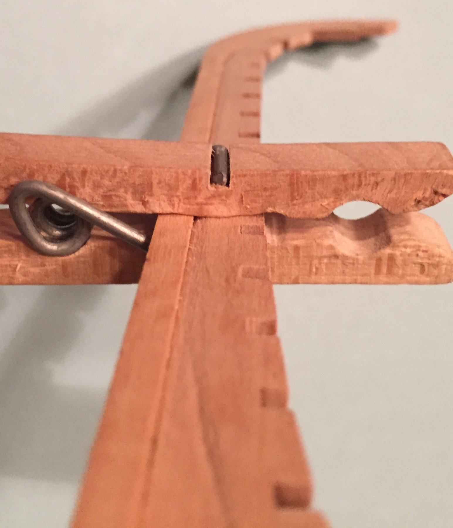
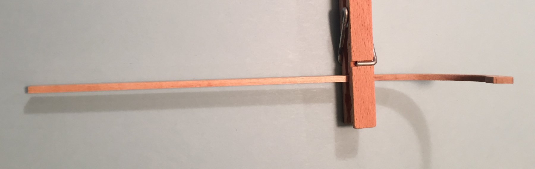
Assembly of false keel to stem and keel. Now that the stem and keel are together and all the char has been removed from these parts and the false keel, it is time to put them together. How do you attach a 1/32nd sliver of wood to the 3/32nds keel and stem? You will assemble the parts on a flat surface. This will position the the false keel right down the middle of keel and stem. There is still plenty of untouched material on the false keel to enable it to lay flat on the work surface. Here is the procedure I used. 1. Dry fit the assembly to insure you know it will go together and where you may find it necessary apply initial pressure with your fingers to establish the initial bond. Make sure the stem piece at the bow is in the correct position according to the plans. 2. Have a damp q-tip (NOT WET) or small portion of a paper towel ready to clean up any glue. 3. Have your clothespins ready to clamp the part. 5. Put the white glue on the bottom and fore part of the false keel only. You should do this sparingly. If any spills over to the sides of the false keel you should wipe it off before you assemble the part to the stem and keel. Work quickly. 6. Lay the false keel flat on the work surface. Because the false keel has been tapered, theoretically no glue or very little will come into contact with the work surface. 7. Position the stem and keel onto the false keel at the correct location and press together until the initial bond occurs. With a damp paper towel very quickly remove any excess glue from one side of the assembly in the rabbet that has been created. Be careful not to flood the joint with water or you will dissolve and break the bond. 8. Turn over the part very carefully and remove the glue from the rabbet on that side. 9. Continue to apply pressure with your fingers to allow more time for the initial bond to harden and set. After a minute or two you should be able to very carefully pick up the part to clamp it with your clothespins. 10. You will clamp the part first in the middle and work your way forward and aft alternatively. Middle, then slightly aft, then slightly forward, then aft, then forward etc. 11. Note from the photo's below that I am using the flat portion on the inside of the clothespin to clamp the two parts together. I used as many as I could get on the part. 12. Put the assembly aside overnight to set.
-
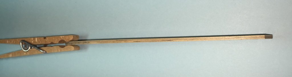
Stem and keel assembly. I departed from the instructions. I wanted a very good fit and bond at the scarf joint between the two parts and I reasoned that attaching this complete assembly to the false keel at one time would be easier and achieve a better result using white glue. It is apparent from the instructions and his build log here at MSW that Chuck is using CA to assemble some components of the model. Others here at MSW are also. CA offers an almost instant bond between two parts and the only clamping necessary is to provide enough pressure for a few seconds with your fingers for the bond to set. A few seconds later you can add the next part. In this case the process in the instructions was to attach the stem and then the keel. CA can be unforgiving and is hard to de-bond and clean up if you make an error. White glue is very forgiving by comparison. Remove the char on both pieces. Be especially careful on the joint to insure that you do not take off too much material. On a flat surface put the pieces together to insure that they fit together correctly. Now you should work quickly to apply glue to the joint and press together on the flat surface. Immediately remove the excess glue from the three exposed sides. Then continue to press together with your fingers until the bond catches. (The best clamps you will ever own are a matched pair, one each of a right and left hand) Very carefully turn over on the other side, clean any glue off this now exposed side and continue to press. The glue will set enough for you to pick up the part without movement at the joint to enable you to put a clothespin on the joint to clamp it. See the photos below and note that the stem and keel fit in the clothespin at the second and smaller indentation. Then lay it aside for the glue to further set and dry. The instructions on the glue bottle says it will set in 35 minutes. I left mine over night, you should too, before removing the clamp and working with the part any further.

-
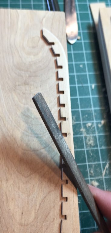
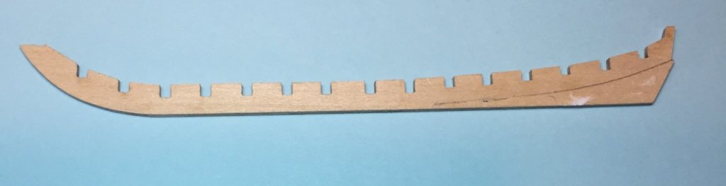
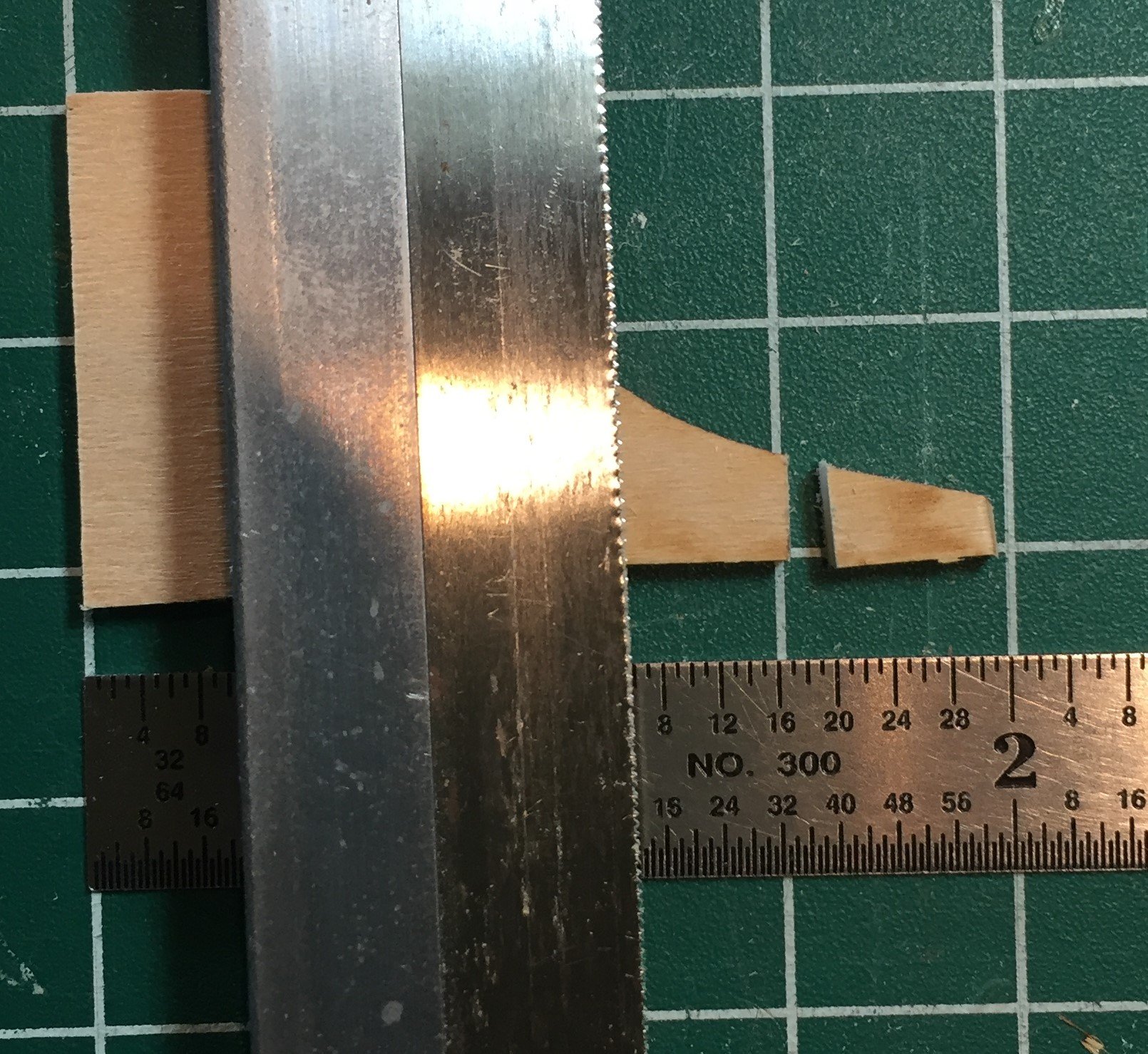
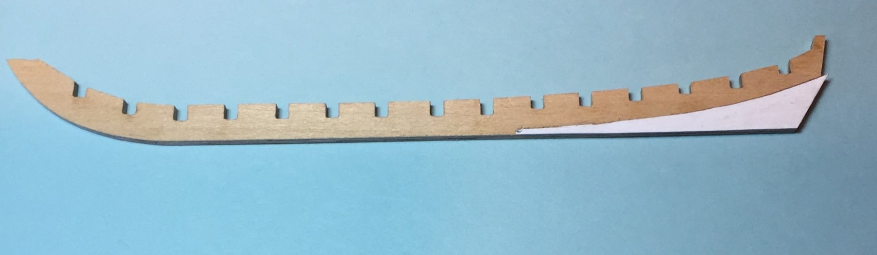
Now it is time to remove the material from below the bearding line. I tried many of my files, sanding block and knives to attempt to get this done. The Sanding block was a fail because my fingers while holding the false keel got in the way at the angle required and I could not see the work piece as I progressed. I then tried using my files. I found that the flat file from the large set worked very well, especially at the edges where the false rabbet will be. Another from the same set with a flat side also worked as well at this part of the task. I used that building board material, placed on top of my sanding block and used my fingers to hold the false keel in place while I worked the edges with the file in a short circular motion while moving the file forward and aft on the false keel. Putting the building board material on top of my sanding block provided the height necessary from the counter top surface to work the file. Here is a photo. No one was around to help take it so my left hand is holding the camera rather that the false keel to hold it in place on the edge of the board. Go slow. Do not be in a hurry and take off too much material. Work one side for a little while and then turn it over and work the other side and Gradually reduce the thickness of the piece. You will soon find the correct angle of the file to establish the rabbet line for the length of the piece. I found it surprisingly easy. Stop constantly and look at the bottom to check your progress toward those parallel lines you placed on the false keel. Do not try and complete it all in one go. After some progress I began removing material from the bearding line at the stern. I tried my knifes and decided it was a no go. I was not comfortable using them on such a small and CRITICAL PART. There is only one of these in the kit. I thought it too possible to take off too much material especially for a beginner. Shaving wood off a part with a scalpel is best left for larger parts and less critical and replaceable parts and a skill to develop later. Therefore I continued to use my files. It is a small part and a small model. There is not a lot of material to be removed. It may take you awhile to get it done, but take your time and eventually it will get done. I also used a sanding stick on this part. Here is a picture of all the files I used to remove the material from the bearding line. I did use my miniature file set, but strictly speaking it may not have been necessary to use. Here is a picture of all the tools I used to accomplish this task. Here is my completed false keel. It does not show very well in the photo. Here is a photo of the before and after. A 3/32nds width piece from the sheet and the 1/32nd width false keel and bearding line. Upon review of this photo, it also does not show very well. The black line is a portion of one of the pencil lines I left in place. It is the edge of the bottom portion to the false keel The material on top of the line is the reduction angle from the full width to the pencil line. You will get to a point where you may not be sure if you should take off more material. I got to that point and put it aside until the next day. The next day I decided that enough was enough and left the part as it was, remaining pencil line not withstanding. Next we will assemble the keel.
-
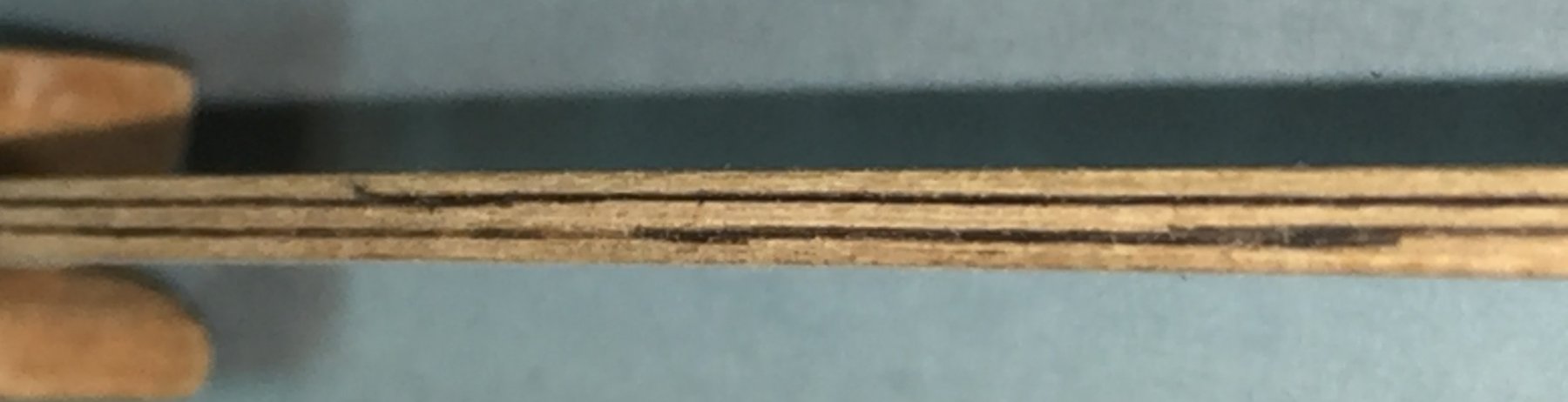
Jim and Andy thanks for your support. As Jim advised, I edited my Always rule above regarding the orientation of bulkheads. Before I proceed with the method of creating the false rabbet I wish to advise that I will be constructing a small building board to hold the model while I set up the bulkheads and plank the boat. I have selected a relatively short piece of 13 layer, birch veneer ply wood. It was left over from a kitchen remodel years ago. I picked it up and other scraps before the contractor thew it in the dumpster. I just knew I would need it some day. I mention it now because it will appear in some upcoming photos being used as an ad-hock tool. I have found it very useful prior to creating the building board. If you do not have a suitable piece of scrap, go to Lowes or Home Depot and look at their wood pile of end cuts. You should be able to find something there for cheap. You will note that I have already drawn a line down the center.
-
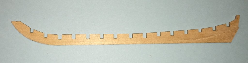
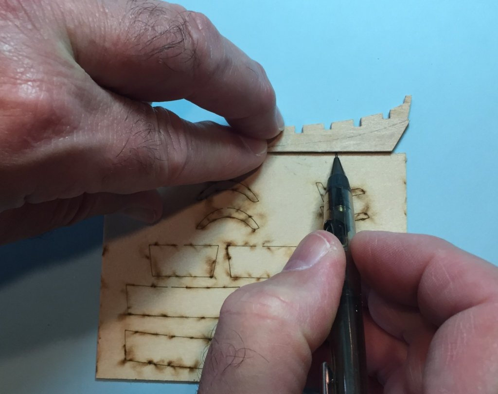
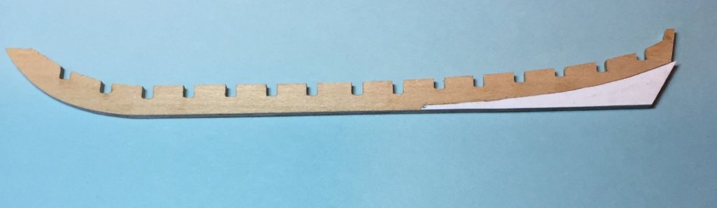
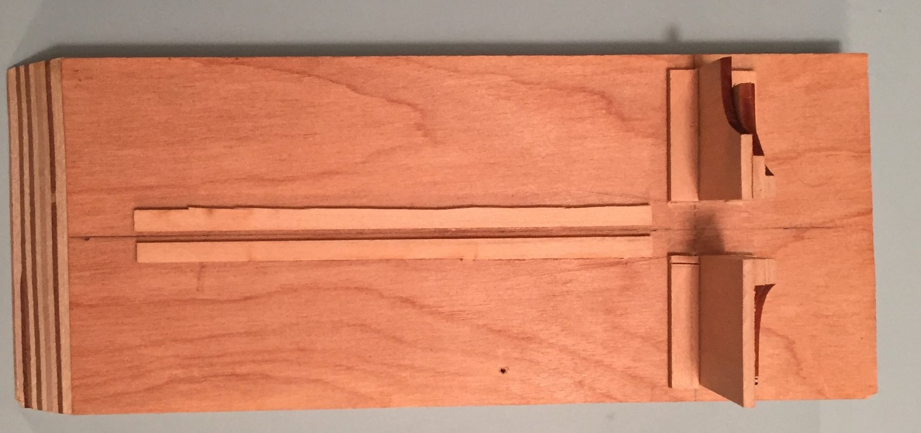
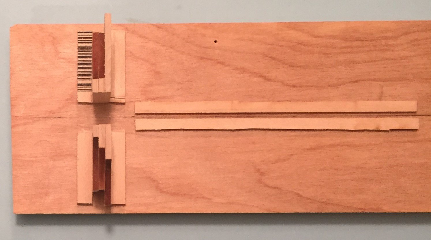
Creating the simulated rabbet/Cutting the Bearding line The instructions advise, and the kit requires you to create a simulated rabbet by removing material from the bottom edge of the false keel and the bearding area. You are required to reduce the material from 3/32nds to 1/32nd on the bottom edge right down the middle of the part. I decided it would help if I could see where I was going with that. Luckily I have a sharp pencil and that the benches and locker material in the kit is cut from 1/32nd sheet material. Get a sharp pencil. I read years ago, either by Harold Hahn or Charles Davis, that it was amazing that people did not appreciate the usefulness of a really sharp pencil, nor did people generally know how to really sharpen one. In ship modeling and drafting, ONE MILLIMETER IS A VAST DISTANCE. A very sharp pencil allows you to draw lines with superior accuracy. I have used a Mechanical Pentel 0.5 pencil for what now seems my entire life. I have had this pencil since college and it stays in my tool box. To get a sharp point on this pencil I simply hold it at an angle to the fine sandpaper on the inside surface (the adhesive edge of the paper wraps around the edge) of my sanding block and sand it down to a very sharp point. Take the 1/32nd sheet that the locker and benches are made and on a flat surface press that sheet firmly against the bottom edge of the false keel and draw a line on the edge of the false keel all the way around. You will have to reposition the sheet a few times, especially at the bow. You will end up with a fine pencil line 1/32nd from one edge of the 3/32nds false keel. TURN OVER the false keel and repeat. The result will now be that you have two parallel lines drawn down the center of the false keel and their inside edges will 1/32nd a part. Now you have a guide to work with and you will work the part to close to the inside edge of the drawn line. See the photo's below.

-
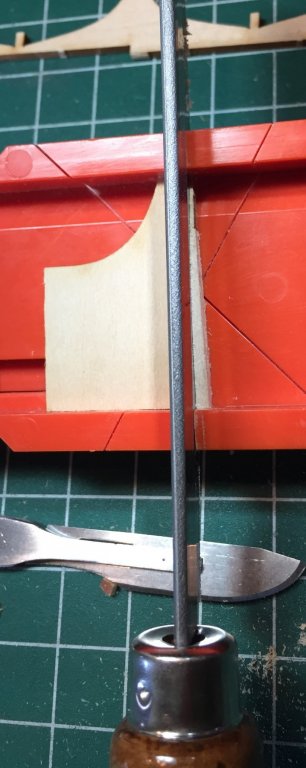
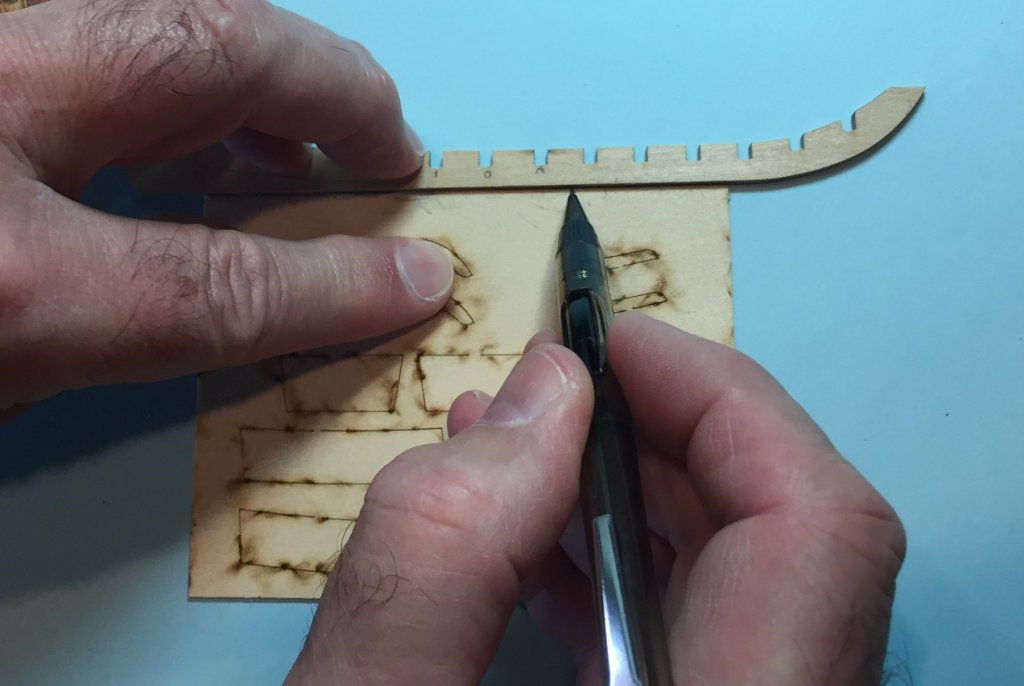
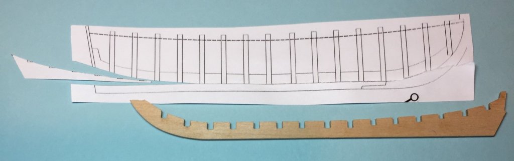
THE BEARDING LINE The bearding line is laser burned only on one side(starboard) of the false keel. How do you transfer it to the port side.? 1. Copy the plan. 2. Cut out the bearding area from the plan. 3. With white glue, glue the profile of the bearding area to the port side of the the false keel. 4. With a sharp pencil draw the curving line onto the false keel. 5. Remove the paper. With any luck, you transferred the line so fast the glue did not set and you can clean up the part with a wet paper towel. If not it does not matter because you are going to sand and file away all the wood that the paper stuck to. See the photo's below. 6. I then took my #21 scalpel blade(it has a curve) and very carefully cut (a rocking back and forth procedure) an indent on the line to create the same kind of edge on the line that the laser burn did on the starboard side.
-
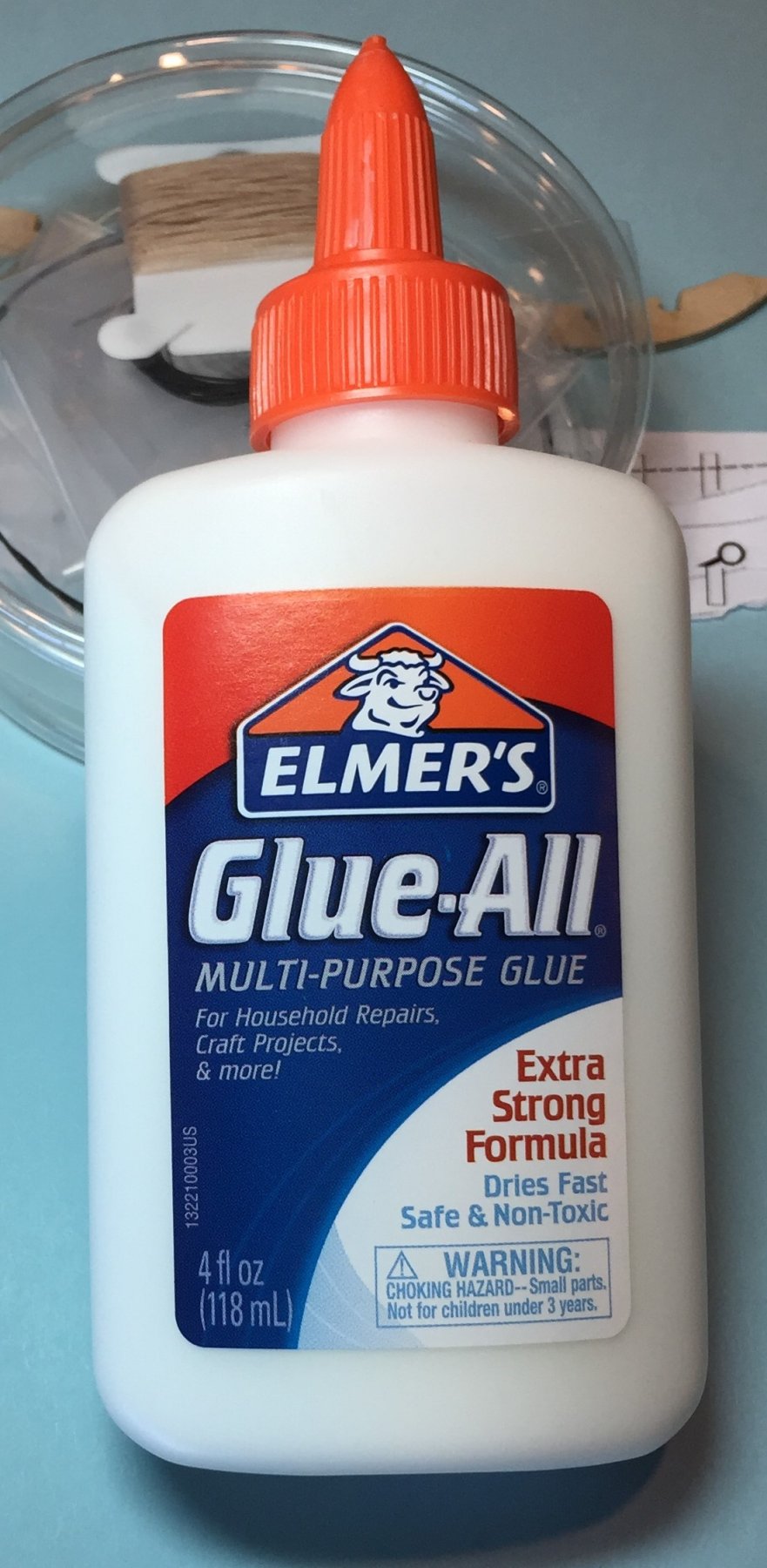
I have decided to use White "Elmer's Glue All" to assemble this model. This was a huge departure for me because I have always used Yellow Wood Glue in the past, either Elmer's Wood Glue or Tite Bond II, both of which are water resistant. I live in South West Florida, a Very Very High Humidity environment. I always thought it the best choice for me. However, over the years I have always met modelers who use white glue and insist they have no issues with it. The clincher for me was David Antscherl. I just completed reading his new book, "The Greenwich Hospital barge of 1832 and methods of building open boats." He uses White Glue to build his very fragile small boats. The advantages white glue has over yellow glue are: 1. It dries clear!!!!! Not Yellow. On an open boat this is a huge advantage. The glue will allow a neater appearance. 2. You can more easily remove White Glue. It comes away with water and as David Antscherl says with alcohol judiciously applied with a very small brush. The alcohol dissolves it. You must be careful however because too much alcohol will destroy the bond and the boat will fall apart. 3. Because this is a small boat, parts of the interior will be visible. However, many parts will be hidden by floor boards, gunnel, and thwarts. Removal of Glue from the visible parts is a big advantage to the novice. It will allow a clean presentation over much of the model. So there is no mistake what glue I am using, here is a picture. As I go through the build there will be opportunities to practice removing the glue before I reach critical areas of the boat.

-
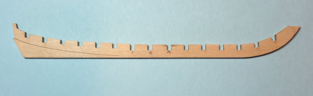
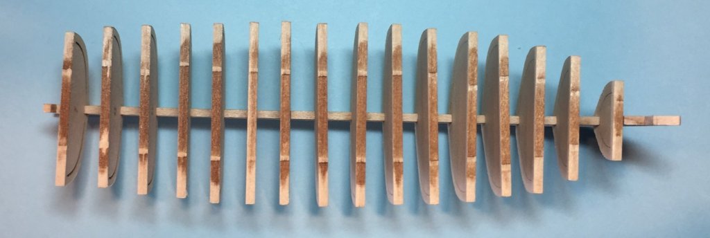
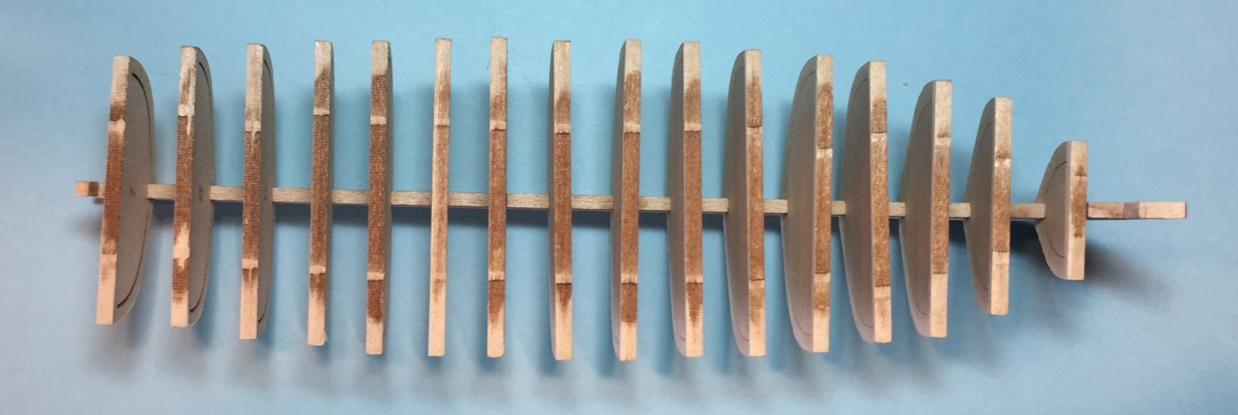
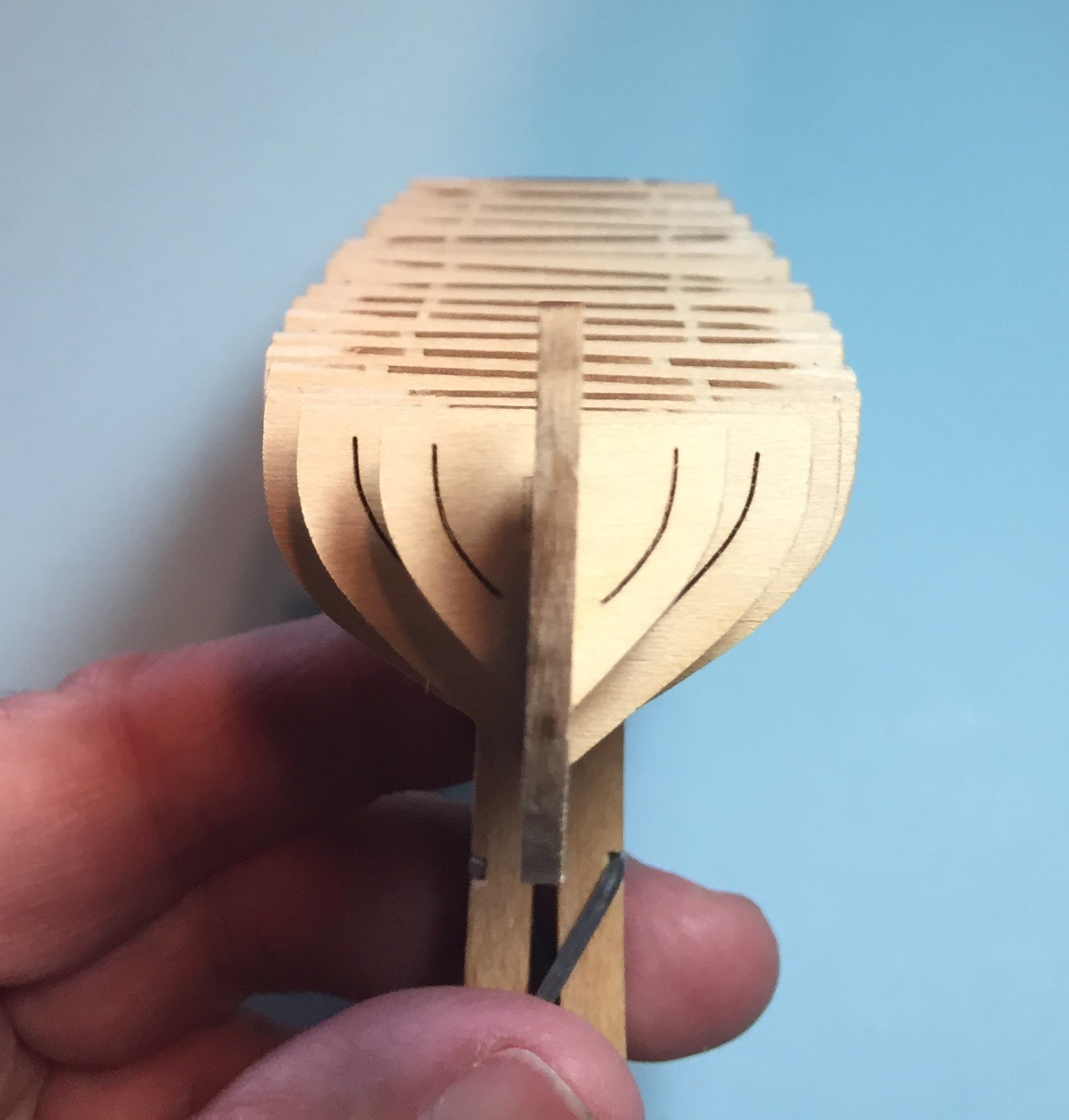
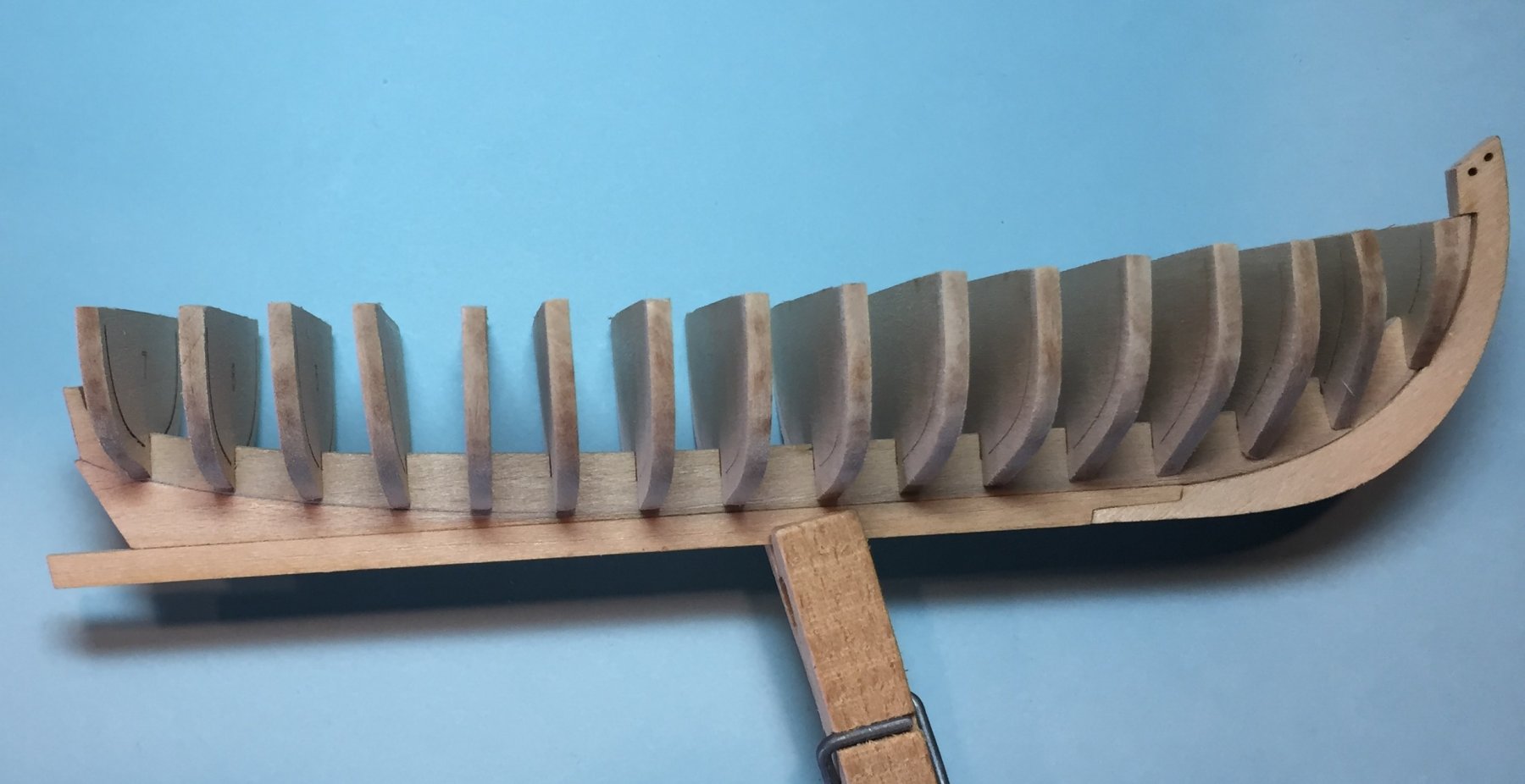
SOME BASIC GUIDELINES AS YOU BEGIN TO WORK THE MODEL. 1. All of the bulkheads should have their letter or number burned into them. In my kit, bulkhead "E" was not labeled. If any of your bulkheads are not labeled, you should label them BEFORE you remove them from the sheet. See the photo above where I have penciled bulkhead E with its letter. 2. As you work the bulkheads and false keel you should ALWAYS maintain the same orientation of each bulkhead to the false keel. ALL THE LETTERS AND NUMBERS SHOULD ALWAYS FACE THE BOW/STEM/FORWARD/FRONT/FORE/THE POINTY END of the boat. This will result in each bulkhead having a fixed port and starboard side. If you do not, you will undo your adjustment to the bulkhead and false keel on one side, causing you to take off more material than needed and then compensating for that error on the other side of the boat. It compounds the initial error and will require lots more work to fix it. EDIT Jim Rogers has suggested a qualification of the above stated ALWAYS rule. Some kits (Model Shipways Syren) require that you switch the orientation of the bulkheads so that in the fore part of the ship the etched letters face forward and the etched numbered bulkheads face aft. This is because in this kit, and some others, the laser cutting of the bulkhead also cuts or etches a bevel line in the bulkhead that is necessary for fairing the hull, reducing the amount of guess work in fairing the hull. It is a line that you will fair the bulkhead or produce the bevel to that etched line. As he says below, and I say above, read the instructions. 5/11/18 The slots in the false keel and the bulkheads ARE NOT UNIVERSAL. One size does not fit all. Just look at the plans and the false keel and you will see that the slots on the false keel are not universally deep. The kit is well designed with Laser precision. Each bulkhead has it's own slot. I realize that this may seem an obvious statement, but for beginner's it may not be. DO NOT DECIDE TO REMOVE ALL of the char from the false keel slots and each of the bulkheads independently and then try and fit the bulkheads into the false keel. Prepare one bulkhead and it's corresponding slot in the false keel simultaneously, and then move on to the next bulkhead and slot. 4. You should label with a pencil the slots in the false keel with some of the corresponding bulkhead letters and numbers. I have marked three on mine. They are 0 (zero), A,and slot number 1. And yes, before you ask. I broke it also. I blinked, and when I looked down, it was broken. It fixed very easily however. More on that later. You all should accept as a personal challenge getting through the keel prep and setting up the bulkheads without breaking it. 5. Initially you are just looking for a nice snug dry fit. Do not force the bulkheads into the slots. You may split the wood on the keel and bulkhead if you do. You will make the final adjustments when you actually glue them up. 6. The bulkheads will not magically locate themselves properly orientated to the keel or each other. Just set them all on the false keel and you will see it. Some will sit at angles to port and starboard, and others will sit at angles that cause one side to be high and the other side low and others will lean either forward or aft. Here are photo's of my boat that demonstrates the fine tuning that will be necessary when its time to glue them up. I did not take the photo before I completed the keel assembly. I did not skip a step. Preparing the rabbet, bearding line, and keel assembly will be explained in detail later. 7. You should work the boat from the center forward and from the center aft when it is time to glue in the bulkheads. This will help orientating each successive bulkhead with the one next to it and provide more precision.

-
As requested I now have edited all the above posts to provide for Larger Photographs and I will try to remember to do so in the future.
-
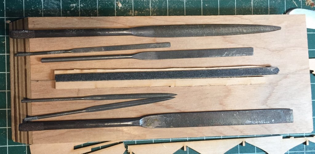
Tool acquisition and costs. Sanding block--a must have. You can however make one or more from a block of wood. Sand paper in various grades----a must have. My sanding block has four grades on it. 60,100,180,and 220. All of them had adhesive on them to adhere to my block. However, you can use rubber cement to adhere the paper to the block if you make one. File sets---I am sure I will use files from the three sets depicted, but it may not be necessary. At this point the mini file set(the most expensive from what I am finding out) may not be necessary. The 5 1/2 and 7 inch sets are very economical as shown below. Sanding sticks--Go to a beauty supply store and have fun picking them out. They are inexpensive. Emory boards are free in some hotels and emory boards in the beauty supply are very inexpensive. They will do just as well as the sanding sticks on this model. Had I thought about it I would have use them instead. I just did not reach for them. SHIPPING COSTS can make a tool very expensive. Watch those charges. I went shopping at Harbor Freight during lunch and look and see what I found. Can not beat the price. These tools will get the job done on this boat.
.thumb.JPG.40e405ff92764b5dffd7c2e8950fd775.JPG)
.thumb.JPG.fc6fd3b6bbdfa1cc29f25e03bc4030a9.JPG)
.thumb.JPG.68a986659ae02d9c00032f1530e58321.JPG)
-
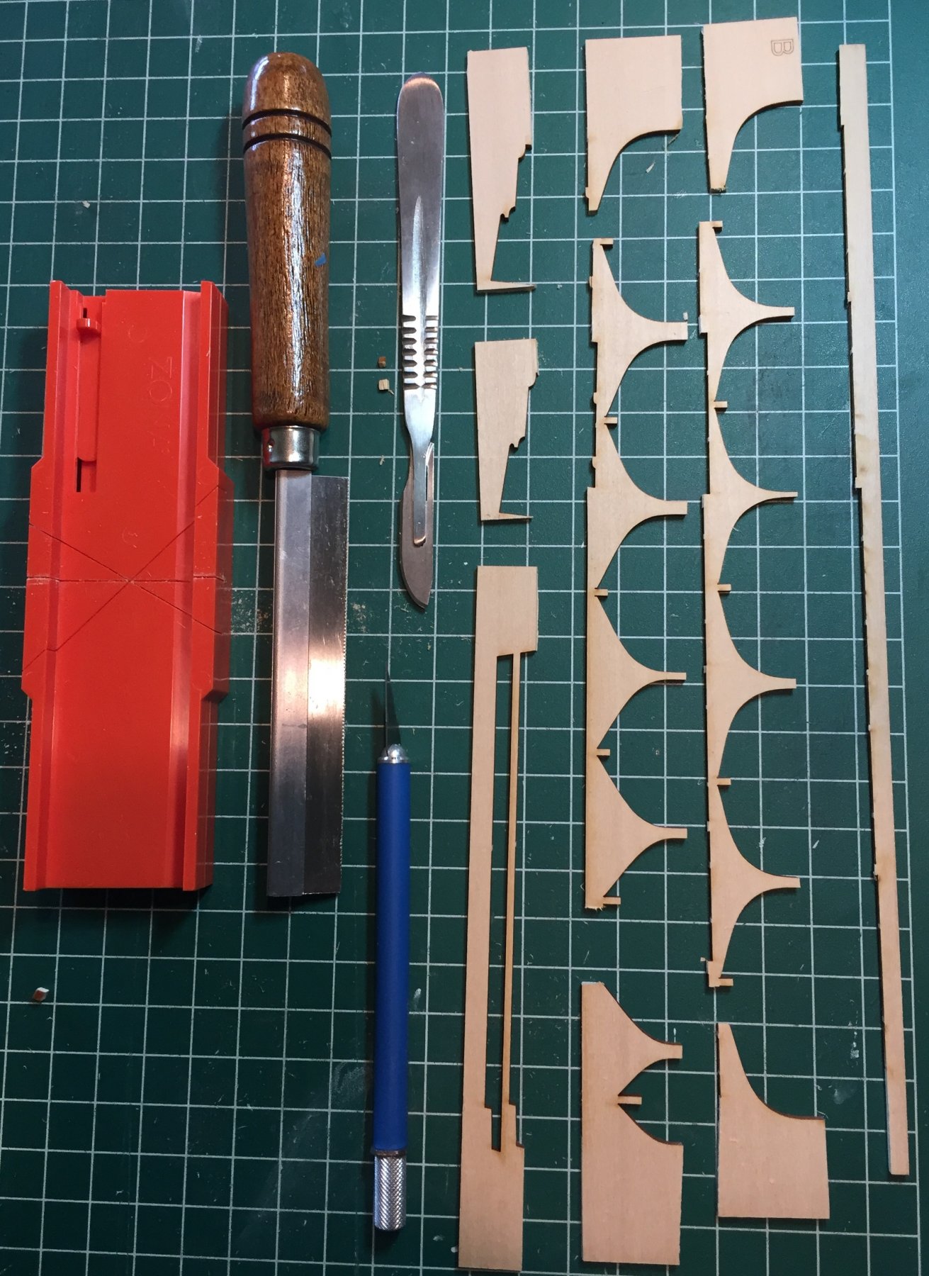
Tools and techniques. PLEASE SEE MY POST FOLLOWING THE TOOL ACQUISITION POST FOR SOME BASIC MODELING TIPS AND TECHNIQUES BEFORE YOU PROCEED TO WORK THE MODEL. Below are the tools I used to complete more the task of removing the Char/burn. First you have the cut the parts out. A couple years ago I switched to scalpel knives and blades. They are very inexpensive on Ebay. I started a thread a while back on MSW called "Is there a better #11 blade handle". I will try to find the link later. I use them almost exclusively now. The craft or hobby Exacto blade is heavy and clumsy. Below are a #4 handle and 21 blade, #7 handle and 11 blade, and a dental handle and 10 blade. I have used the regular craft knife and 11 blade in the build below. If you are a novice at this, please be careful with surgical blades and handles. You will cut yourself fast, you will not know it till you notice the blood spoiling your work. Below are the tools used to file and sand the Char/burn away from the parts. Depicted are parts of three file sets. The ruler is there to let you know the size. I selected many files to try and do the task, thus the three sets. However, the choices to accomplish the majority of the work soon became obvious. The file sets are a miniature needle file set in a blue aluminum holder. One of my most favorite tools and most used. They are 4 inches in total length. A 5 1/2 inch flat file and two files from a 7 inch set. Also is my Sanding block from an old True Sander(my most used tool). It has 4 grits of sand paper on it. Last are the sanding sticks. All of them are coarse grades. The next photo is of the tools I used to do more than 95% of the job. The entire task can be accomplished with these. The most used was the sanding block and wide sanding stick for all those edges. The files were use mostly to remove the Char/Burn from the bottom portion of the bulkheads next to the slots, especially those bulkheads with inverse curves. The narrow sanding sticks and files were used to remove the char/burn from the slots. Turns out that the largest file's width almost matched the width of the slots. With just a little bit of light work the large file fit in the slot and finished the job in a very uniform way. Examine your files. Not all edges will have cutting surfaces. The flat file above is smooth on one edge. It was great in the slot because it did not continue to cut the crotch in the slot. The flat, square and triangle mini files were also great to clean up the slots. Go Slow and do not be too aggressive. PLEASE SEE MY POST FOLLOWING THE TOOL ACQUISITION POST FOR SOME ADDITIONAL BASIC MODELING TIPS AND TECHNIQUES BEFORE YOU PROCEED TO WORK THE MODEL.
.thumb.JPG.27b36038f2b2aef925be5db401b38e86.JPG)
.thumb.JPG.ea9e07b6e6e9b1f86d0372112244b0c9.JPG)
.thumb.JPG.c2fb1eb18685531ed88c8e37c4e11728.JPG)
-
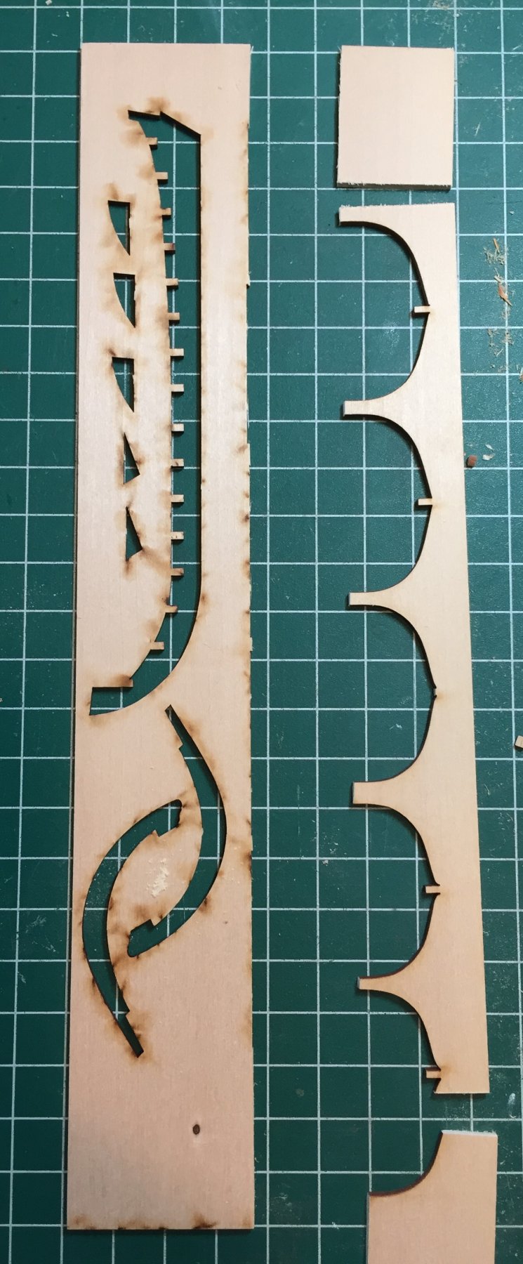
You MUST remove the char or burn that has been created as a result of the laser cutting process. The instructions do not tell you to do this, although the photos of the boat show that the char/burn is removed. If you do not, the glue or adhesive will not bond properly. Because I have chosen to use White "Elmer's Glue All" this may be an even larger concern. I will explain my glue choice later in the log. Please do not complain about the designer or manufacturer of the the kit for omissions in the instructions. In ALL kits they are only meant to be an assembly guide so a modeler with some limited experience can get the model together. They are not meant to teach you BASIC modeling methods. That is what Model Ship World is for. The following are my tips and comments on this task. 1. It is a time consuming task and boredom will set in really fast. It is the chief complaint and draw back of laser cut kits, but the accuracy it provides in the cutting is astounding compared to the older kits where the parts were stamped from a plywood sheet. 2. It will take you far longer to sand and file each bulkhead, false keel, stem, and keel (the parts you need to build the hull) than you might imagine. 3. It is important to take your time and to not be overly aggressive in this task. You do not want to take off the relatively clean wood below the char/burn. It will not be white when you are done. It will look off white and darker than the the untouched areas of the part. DO NOT TRY TO MAKE IT CLEAN. You will remove too much material and change the shape and dimensions of the parts. 4. Of special concern are the crotches of each bulkhead and their counterparts in the false keel. TREAD LIGHTLY HERE! If you take off too much or you are not consistent with the amount you remove you will change the height or depth that each bulkhead sits on the false keel making fairing the hull more difficult. At the time of writing this I have finished this task and discovered much to my joy that my bulkheads sit at a good height and are consistent with each other and the plans. Try to be consistent in the removal on the other surfaces so distances fore and aft also remain relatively consistent. Here are my results. Note the not clean and dark stained look. Also note the top of the bulkhead in the close pin. I removed the edges where the top of the frame will be. In retrospect I do not advise you to do this because the frames will protrude from above the sheer plank and you have to sand or file them level later in the build. Not removing the Char/burn from the top will make measuring their height port and starboard easier when the bulkheads are installed on the false keel later. The next post will explain the techniques and tools used to accomplish this.
.thumb.JPG.c221a7c663d76257ffd13a095ac70c5e.JPG)
-
Tools Tools Tools and Materials This post is being made to create a PLACE HOLDER in the log to keep a list of tools which I am using. I will come back to it and add the tools as I use them. That way all the recommended tools for a beginner to purchase will be here close to the top of the log. If a Moderator or the Administrator can suggest a better way please let me know. I do not know if I can insert posts is a build log or rearrange the order once they are done.
-
Beginning the model. Read the entire instruction booklet before you begin. Its more important to do this than you might think. Every model book, guide and kit manufacturer tells you do this. Make sure all the parts are there as every model book, guide and kit manufacturer tells you to do. Knowing what comes next will help you organize your work and any required tool or material purchase. Most important you will know which parts are missing and to order them from the manufacturer. I went through the instruction book twice and discovered that it does not actually tell you that there are duplicate parts (extra parts) in the kit. Below are the photos of the the extra parts in the kit. The extra parts are the Keel, Rudder, Stem, Bow filler block, and stern post.
.thumb.JPG.d80213d70e2310123ad9a65b0bdf9d96.JPG)
.thumb.JPG.9a2095e1c44446dfa625015d2f2a7188.JPG)
-
Chuck and Paul CHALLENGE ACCEPTED
-
I will adhere to some strict ground rules for building this boat. They are below. 1. I will use only basic hand tools. 2. I will not use any power tools. 3. I will document my tool use as I use them. I will try different tools to achieve the result in order to determine what is the best tool to complete the job. Where appropriate I will advise you what tools I tried. 4. I will TRY to keep the costs down by limiting the choices and the variety of tools and other materials. This is already turning into the hardest part of the build because if I need something I naturally reach for it to do the job. I have caught myself already on more than one occasion. There are tools that may make a portion of any particular job easier, but if it requires making a special purchase to obtain it, I will refrain from using the tool. The best example I can think of now are steel angle blocks for bulkhead alignment and for weights. 5. I will use tools I already own and routinely use. I have been amazed over the years at how few tools I use for 90 percent of actual modeling work. I will not handicap myself by not using my favorites. The best example here is my sanding block, which is from a worn out True Sander. 6. There are basic tools that will have to be bought or made (a sanding block) and it is unavoidable if you do not own them or already possess suitable other tools. 7. I will attempt to create work a rounds to avoid tool and material purchases. This is more time consuming than you might think. 8. I have not worked it all out in advance and as I go along I might have to change the processes and edit previous posts. Where appropriate I will notify all when I have to edit. 9. I will use my personal books to help problem solve, although a beginner will not necessarily have access to, or the desire to purchase books to complete this model. 10. THIS IS NOT A GROUP BUILD----This build log is for posterity. I am the slowest and most time consuming ship modeler on the face of the earth. I am still fully employed and finding time to model is hard to balance against work and family. If you wait on me to get to the next step in the model, I would suggest that you take up stamp collecting while you wait. 11. I have already received private feed back on my opinion that the Long Boat is a good choice for the beginner. I may change my mind about that when I get to the end. I also invite private feed back from all my friends and others on Model Ship World if you can suggest a better way to achieve the result. I will give full credit for the suggestions, and perhaps it will make a cleaner and more concise build log if they are incorporated that way rather than replies within the log. Help is always welcome, so if you want, send a private message and I will provide my email.
-
Hello All I have decided to build my Model Shipways kit of the 18th Century Long Boat. In order to make the build log a little bit different than the others here I am gearing it for the beginner who has never built a ship model before. I and I alone have decided its a good kit for the beginner for the following reasons. 1. The model has a very modest cost compared to others, especially if you catch a sale. At the time of writing this it is listed at $49.99 without entering a sales code on the website. I paid less for mine. 2. Model Shipways quality control is very high and their free replacement parts for missing or broken parts is superb. Although made completely from bass wood Model Shipways strives for the best it can put in the kit. 3. Bass wood is a good material for a beginner. 4. The hull itself will introduce the beginner to most basic hull construction techniques found in many kits. It is a plank on bulkhead constructed kit that when the bulkheads are removed, it turns into a plank on frame construct. 5. Although the planking may cause some difficulty to the beginner because it is only a single layer and errors will show, it is a small hull and the planking lengths should be easy to accomplish. 6. The kit presents a subject with a simplified rig that should not place a barrier between the builder and the finish line. 7. The number of tools needed to build the boat should be limited. I will adhere to some very strict ground rules for the build log. Mostly related to tool use. Those will be in my next post.


.JPG.6592cacb9ddcca17fa4f83e05a356819.JPG)


.JPG.10706fa60c7fa4273db6145241c58378.JPG)

.JPG.230c888c5a72dbef140f3b12d59a7da1.JPG)


.JPG.5382e3f224f36086419f7332386894b1.JPG)
.JPG.394a70f5b5b02173bdf12f32f375312a.JPG)
.JPG.83adced724af3008eac826ca6d38d158.JPG)
.JPG.d056d50b5b359a191f0ef76bc44e1c44.JPG)
.JPG.18817dbc29301b8a38959d38c0c4b8f1.JPG)
.JPG.963ae2c49df6ebe610d292577f2a3c84.JPG)
.JPG.9a315452344dbfd2ebddca472ca1feb2.JPG)
.JPG.2f0c011b6b905ba3954d3e969b36676f.JPG)
.JPG.010094823ac211dce2be343b64372a8b.JPG)