HOLIDAY DONATION DRIVE - SUPPORT MSW - DO YOUR PART TO KEEP THIS GREAT FORUM GOING! (Only 13 donations so far - C'mon guys!)
×


roach101761
-
Posts
204 -
Joined
-
Last visited
Content Type
Profiles
Forums
Gallery
Events
Everything posted by roach101761
-
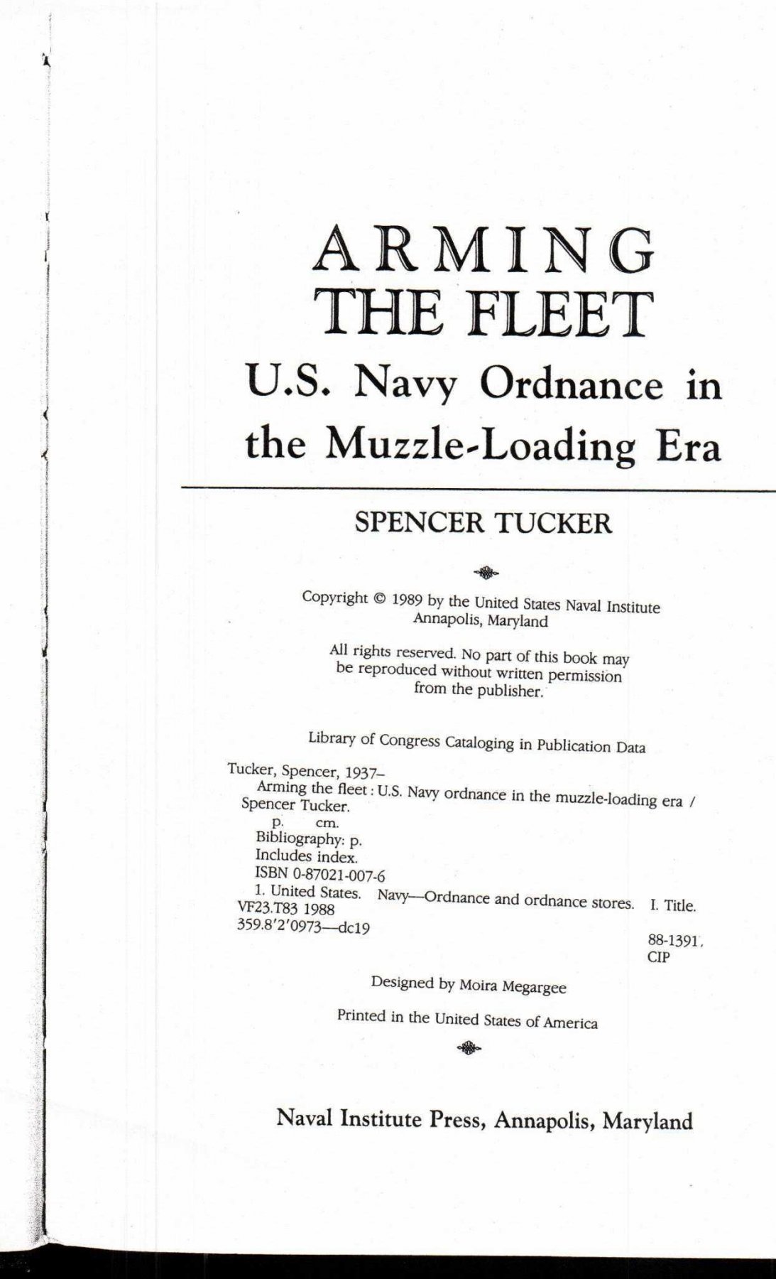
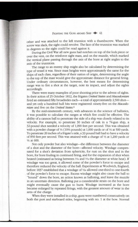
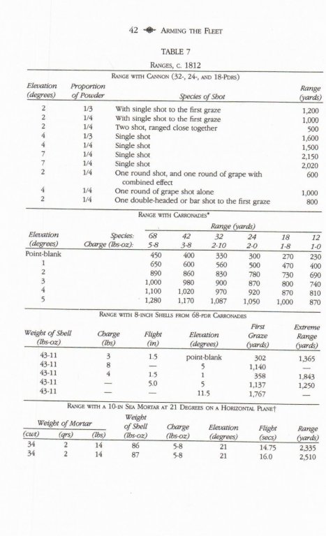
I have found some information on ranges and velocity for our muzzle loading naval cannons. I found it in the book Arming the Fleet, U.S. Navy Ordnance in the the Muzzle-Loading Era by Spencer Tucker published the the Naval Institute Press in 1989. I always give full credit. I believe posting this information below is within the educational exception for copyrighted works. I was surprised at the ranges indicated in the chart. I am not sure they are effective ranges. The text contains information about the state of the art at about 1850.

-
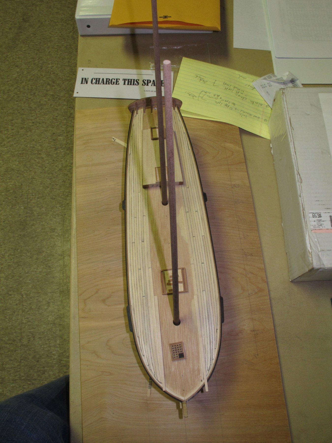
What type of wood is the mast? Is it too soft or is it too brittle/ Perhaps making the mast from a harder wood or more rigid wood will do the trick. Phil
-
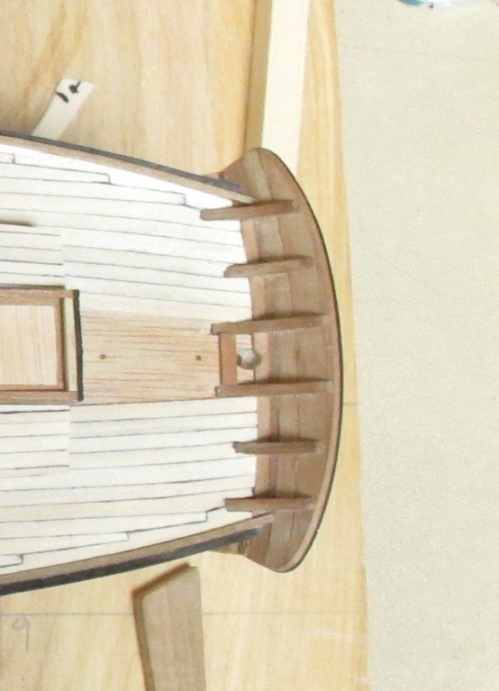
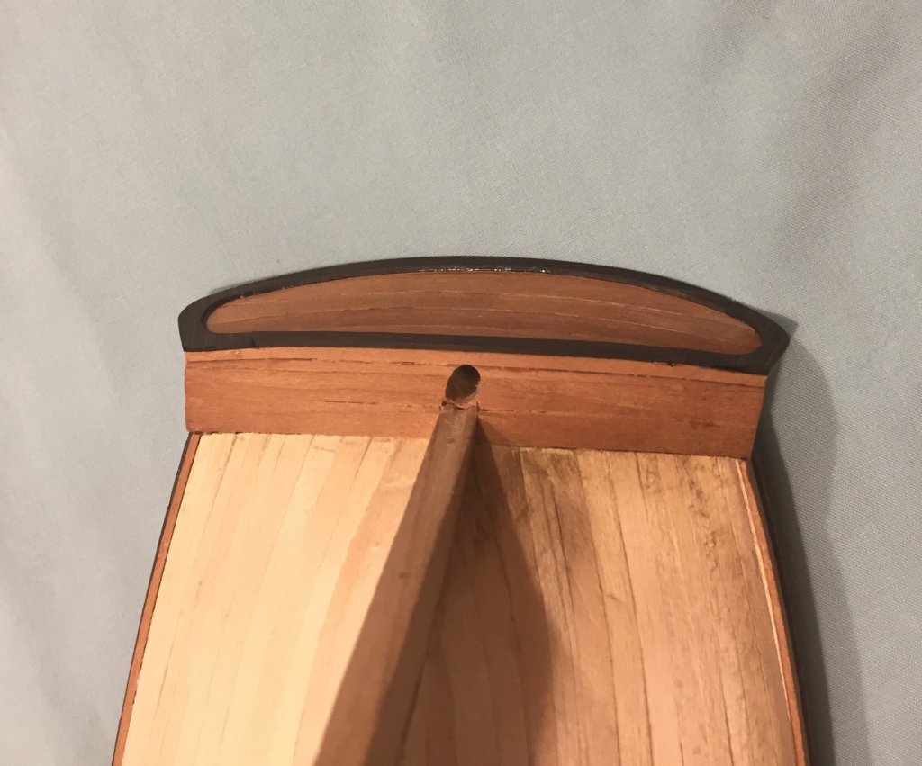
I posting this picture again because after reviewing above I determined that I left out a step. I cut filler pieces and inserted them between each of the stern timbers to set the curve at the stern and to fill the gaps. Each one is also cherry.
-
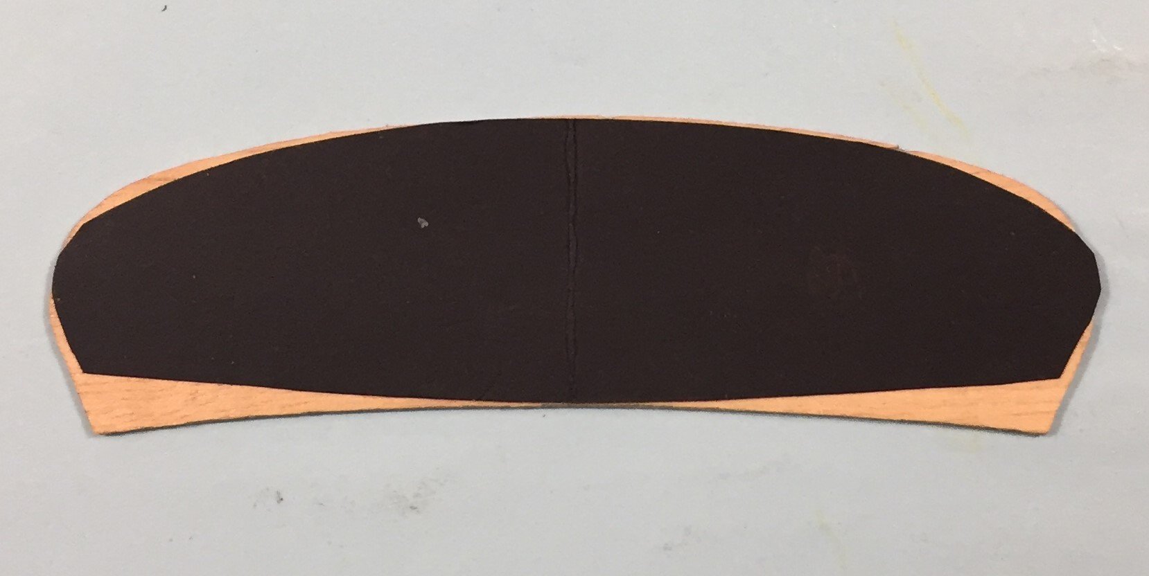
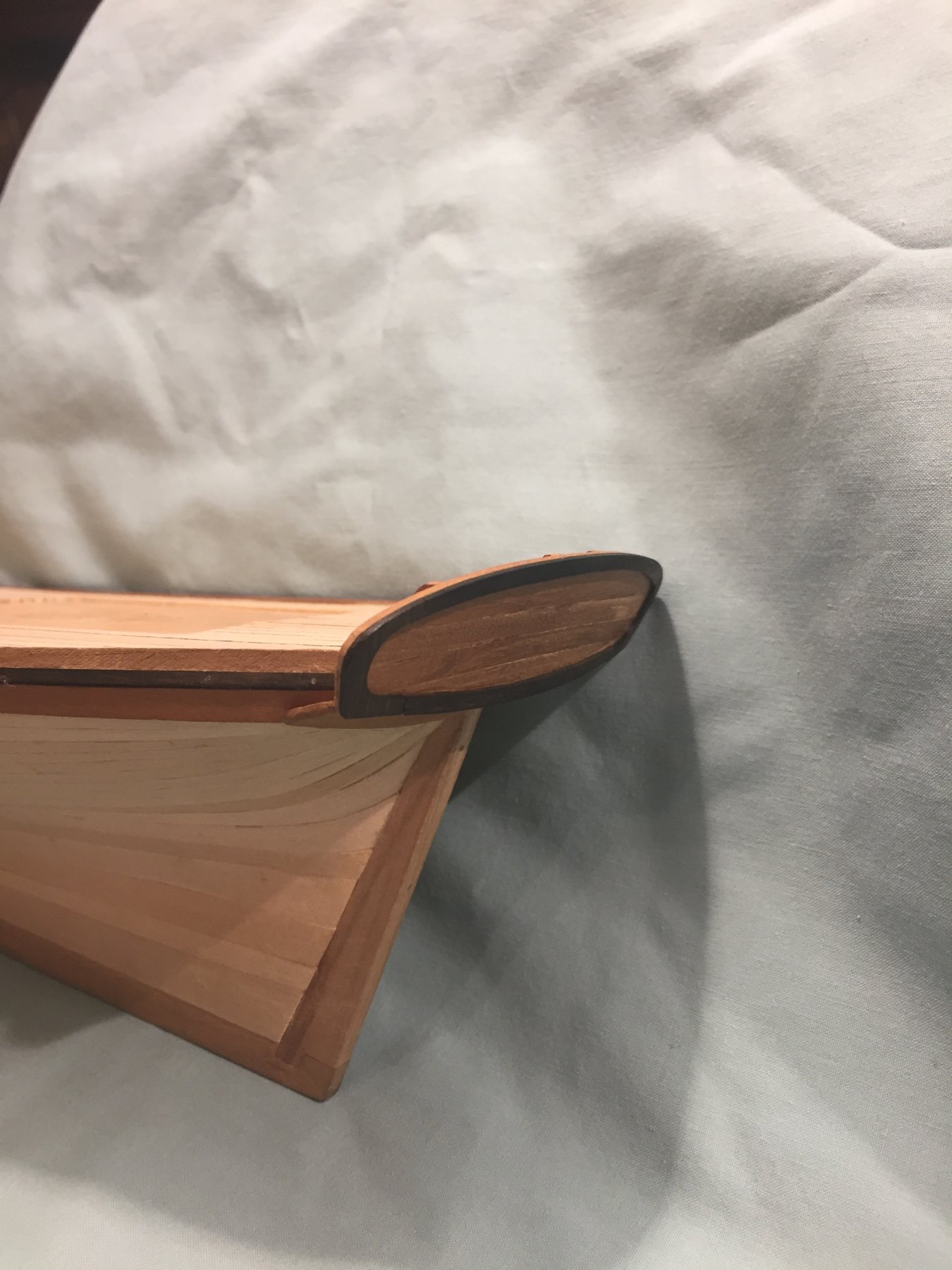
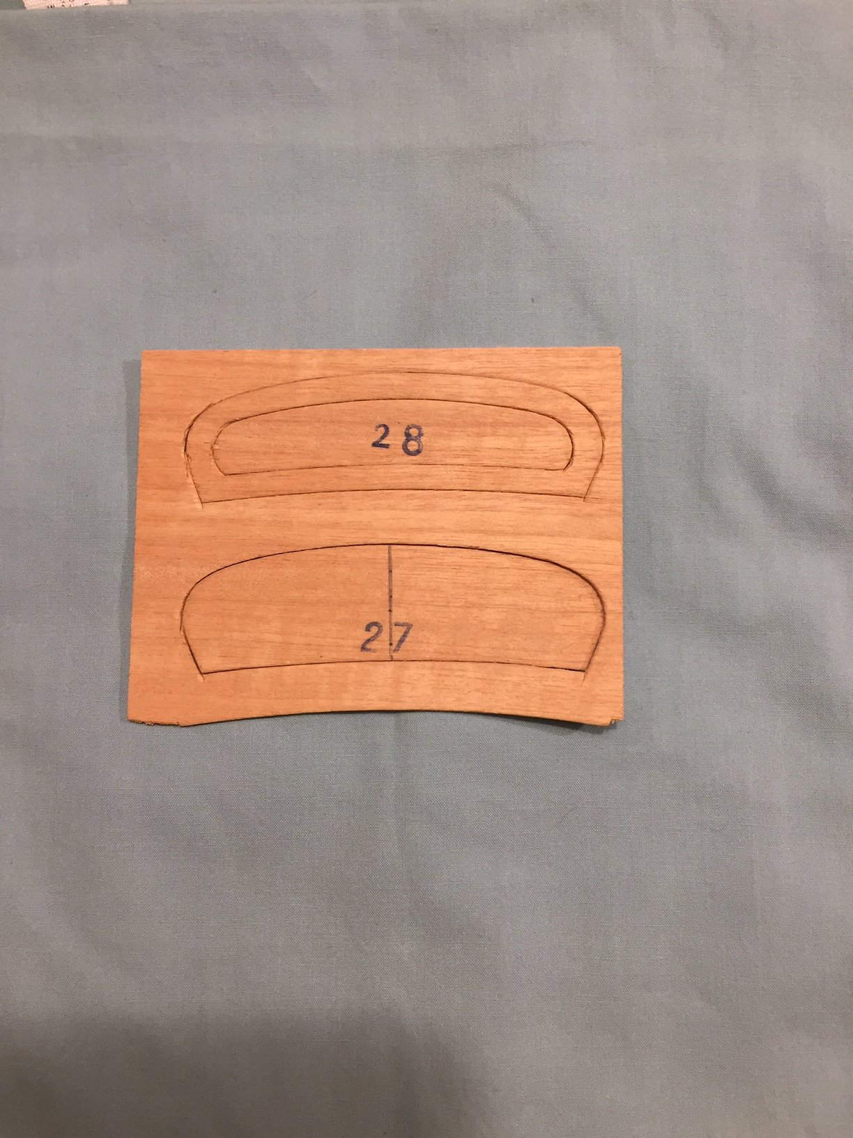
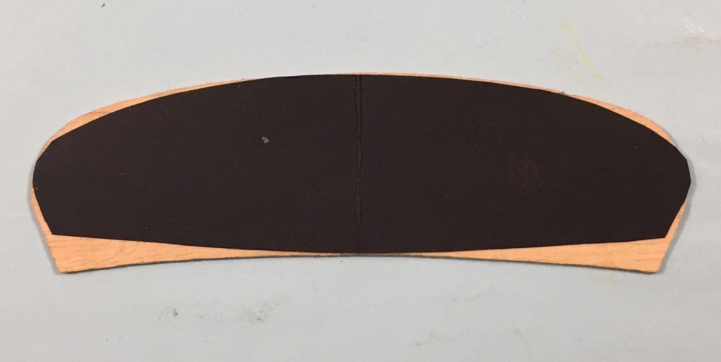
I have not been on in a month. I will now describe the construction of the fashion piece which is the decorative ebony framing on the after side of the transom. I needed to shape the transom to it's final configuration to and shape the fashion piece. To do this I started with the kit part and made a pattern of it. It nearly matched the transom I built on the top of the rail. You can see that the shape of the transom that I ended up with at the counter and the wings was very different than the kit part. This photo is below. I then folded it in half to insure the port and starboard matched each other. I then took some thin ebony and made the port and starboard side. I then cut and shaped the top and bottom portions. When the overall shape was close (I made the whole assembly a little over large) I then attached the the two sides to the transom with 5 min. epoxy. I then fit, cut and shaped the top and bottom portions and attached them with 5 min epoxy. This assembly was a little over large on all four sides. I then final shaped the transom piece to fit the built cherry planking transom. From the photo's you can see the result. I still have some glue/epoxy clean up/removal to do. The next challenge with this transom is to create a top rail in on piece that wraps the entire edge around and down each side to where the wings attach to the hull. Still trying to work that out.


-
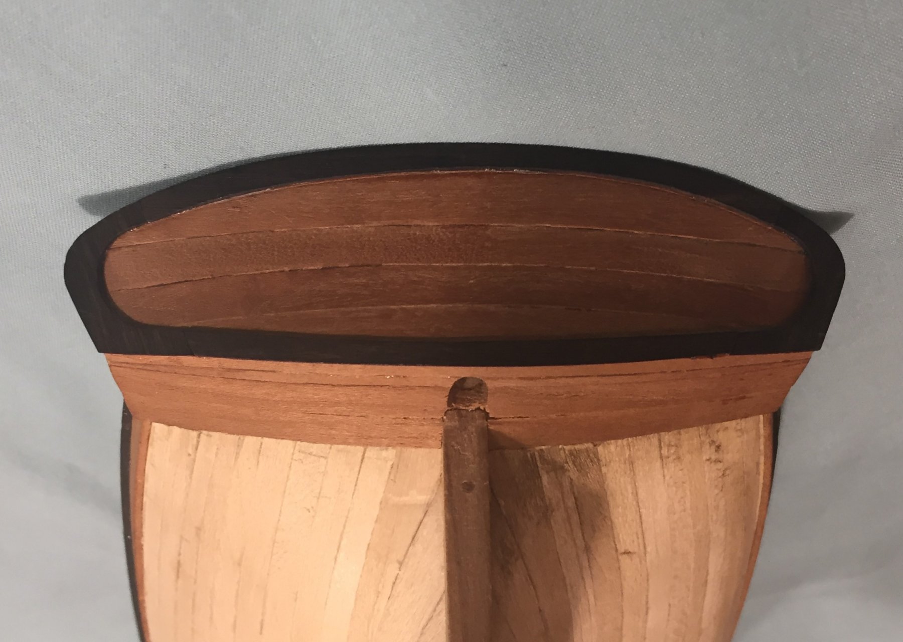
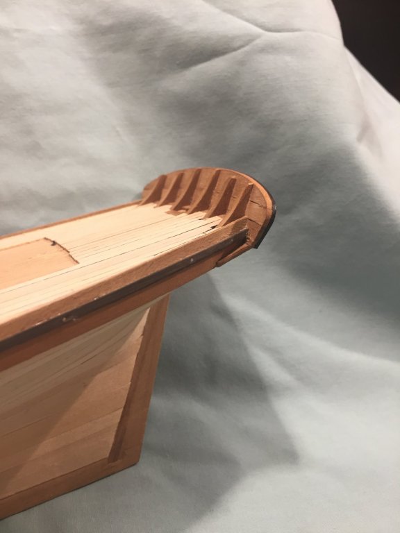
On to building the Transom. My stern timbers were cut from cherry stock. They were basically triangle shaped. I approximated the angle and prepared a large blank. I sliced them at the correct thickness and then placed one blank into each slot I cut in the un-planked sub deck that I cut on my table saw. The stern of the deck was curved from the center line to each edge. It was also at an angle. I toyed or fiddled or played with the stern timbers and the kit part that was the transom until I was sure of the angle that the stern timbers should take. The counter already built was a big help in establishing the angle. The first plank of the transom that interfaced and meet the counter was going to rule the angle and the the look of the finished transom. The stern timber surfaces with the planks would also have to be angled for curvature from the center line to the deck edges in order for the transom planks to fit flush with the timbers. Because of the angle and bend from the center line to the edge of the deck and counter the planks would take on a downward curvature from the center line. The flat kit part exaggerates this drop. I would need to pre-bend the planks. I created a blank to cut planks from. They are about the same width of the hull planks. To create the downward curve I used the tried and true method for making deck beams. I soaked and heated my blank and held the ends down with weights so when dry it would be a curved piece of wood. I worked like a charm. This was my first attempt at this method and I was very pleasantly surprised that it worked so well and as advertised. The blank was over long. I sliced the number of planks I needed and then some so I would have enough. I then glued each of the stern timbers into the slots. For strength I used 5 minute epoxy. It worked very well. I waited a whole day before putting on the first transom plank. Clamping was not an issue because the stern timbers and counter gave great surfaces to clamp with. I used yellow wood glue for this process. Each day I added a plank. I wanted to make sure I had maximum strength for the cured glue. After the first lower plank the stern timbers themselves were all that I needed for a clamping surface. Before the topmost plank on the transom I began shaping the top and forward parts of the stern timbers. I did this with my Dremel with a drum sander attachment. I also shortened the timbers as they proceeded to the edge of the deck to account for the downward curve the the planks and the transom. forming I used the kit supplied part as a rough guide to shape the transom when the last plank set up. The counter planks forming the wings at the wales provided the starting point for the upward outward sweep of the transom planks. Because I used pre bent planks for the transom the top rail curve was set The knuckles on each side needed rounded down and that is all. Because planks were bent before I sliced them from the blank, the transom almost shaped itself. I left final shaping until I made and fit the fashion piece. Here are two more views of the transom looking from the bow and the port quarter. In these photos I still have some glue clean up to attend to.

-
All good stuff here on velocity. I am somewhat surprised that the muzzle velocity of the 16" guns and the mark 45 are the same and and that they are no faster that a high powered rifle. A 30-6 Springfield has a muzzle velocity of 2700 ft/sec, but depending on load and weight of the bullet can be faster or a bit slower. I understand that a 9mm pistol round is normally about 1700 to 1900 ft/sec. A shot gun goes at 1200. At that speed you can see a shot gun slug travel down range if you position yourself correctly to watch it. I have read that Soldiers and Marines have seen large shells fly over, especially if nearly at the end of their trajectory. I have read on numerous occasions that cannon balls were very visible in their travels from muzzle to impact. Which brings us back to our age of sail small to larger bore cannons. Anybody know the muzzle velocity of these things? I am going to guess very low. Ranges were only a few hundred yards. Effective ranges less so I believe. Short range means low velocity. I think I will go hit the books.
-
Why do you have to remake the part? Why not just add your pear veneer to the current part to get the finish you want. If it will be too thick or over large after the application, sand down your high grade plywood or run it through a thickness sander before you apply the veneer. A lot of kits cover the plywood with a strips of other woods.
-
This topic has intrigued me from the first day it was up. Have been searching my books and my memory for 10 days now and can find no references to this type of injury. I really appreciate the responses from our military members. I read a lot of history and military stuff other than naval history and always have. Guess what I never read about? I never read about a military person later in their life being completely deaf by their service. I read all the time about Naval Figures and other Military personnel dying from their wounds years later, but never being deaf years later. The more I think about it the more sense the responses about the pressure wave and that the real danger is from constant noise for years. Think about this. If in every sea battle you were doomed to lose your hearing permanently, or in a land battle with artillery, why would you service the gun? The weapon itself would not be used and would never be developed. A weapon must be safe to use or no one will use it. In books, both fiction and non fiction, I read all the time about ears ringing, sometimes temporary hearing loss or blood oozing from the ears, but not injuries from using the weapon directed at others. Soldiers in concrete bunkers in which grenades are tossed are unlucky. My reading says that at least temporary hearing loss is immediate if you are not killed out right. The pressure wave is contained. It sucks to be in the container. About that pressure wave. Most ship guns on smaller vessels and frigates through 1775 were nine pounders or less. How far does the pressure wave on these guns go before they dissipate to harmless levels. Think about the ranges at sea at the time. Close could be anywhere from 100 yards to hailing distance to pistol shot. How about the guys on the target? The ones not protected by the wooden walls. In all my reading of individuals who are on the receiving end of a broadside, I still can find no hearing issues. I think we are back to the pressure wave. Does anyone know how it dissipates over time and space(up, down, sideways, etc)? Things to think about. Perhaps the guns themselves do not create an issue until they are much larger in size and caliber? Perhaps the size and scale of the pressure wave created are simply not big enough.
-
I too am surprised about the breaching rope. What is the purpose of the cascabel if not to secure the breaching rope. I do not think that it can add to the strength of the barrel. Does anyone know?
-
Continuing with the Counter After cutting the slots for the stern timbers and roughly shaping them to the correct angle I decided that I should fix the counter before I progressed. As the deck was not planked yet I had the perfect clamping situation for the planks that would make up the counter. I cut planks from cherry to fill the space of the counter, making them long enough to form that little wing on each side of the hull that interfaces with the transom pieces. The counter has a curvature, being high at the center line with a bend toward the deck on port and starboard. It was not a very great bend and I decided to glue and clamp it in place. I used 5 minute epoxy to insure I had the strength in the bond. Here is a photo of the counter. I possessed the perfect pattern for the piece. The discarded part from the kit. The planks used were roughly the same width as the hull planking. I was assured a flush fit with the hull planking because the counter planks were thicker than the kit part, and I had the opportunity to fill low spots and continue to re-work the base of the counter. If you look , it took two whole planks and part of a third at the interface of the counter and transom. I drilled and cut the hole for the rudder post after the work was done on the counter, having pre-drilled the hole in the false deck and filler pieces. What appears to be a fourth piece is actually the first plank of the of the transom construct. You can also see in this photo that the transom is also curved from the center line slightly sweeping toward the bow. Fitting that small third piece of plank to the counter allowed me to fix the angle it made with the transom. It started as oversized and I was able to work it down to the desired contours of the transom. This process also allowed me to fix the angles of the stern timbers.
-
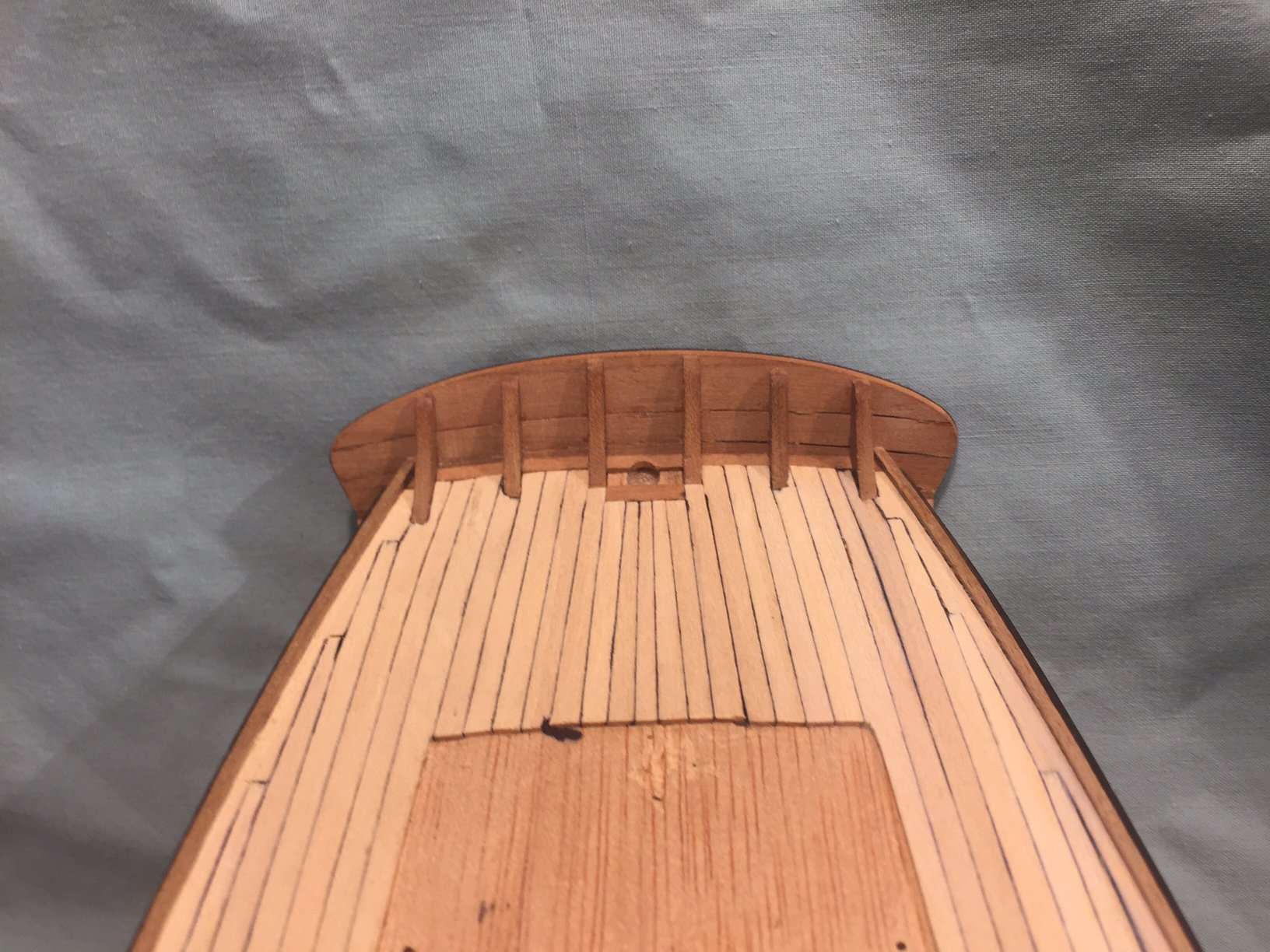
I will begin now on how I constructed the stern on my model. As stated above, all went well with all the filler pieces supplied in the kit for shaping the aft section of hull to where it meets the counter. The final counter piece however proved to be problematic. Because I installed the stern, stem and keel pieces prior to planking, there were also issues with the counter fitting flush with the planking, in addition to the problems associated with the little piece of rigid plywood provided for the counter, It required thicker material for the counter and it needed to be planked(or at least appear to be planked) up. I also needed a new solution for the transom and fashion piece. It also needed to be planked up. Below is and image for the stern from above showing the stern timbers I created from cherry stock. The transom and counter are made from cherry. For the timbers I shaped the stock so as to approximate the proper angle of the transom to the deck. In order to fit the timbers to the hull and deck I cut slots into the lower deck on my table saw. I did not plank the deck prior to this operation. I turned the hull up side down on the table saw, and after careful measurements between cuts(must have measured at least 10 times) and after carefully aligning the hull with the saw and fence(probably did this 20 times) I cut the first slot. All the measurement before cutting was to insure the timbers would be parallel to the keel or center line of the model. I experimented with some scrap to determine the width of the cut, saw blade kerf and thickness of the timbers. I got lucky, the kerf of the blade turned out to be the thickness I needed for the timbers. I cut the timber blanks just a hair wider so I would have an extremely tight fit. I did not worry too much about the length of the cut as it would be covered by the planking. The cuts are not too deep, perhaps just over an 8th of an inch. Because the deck could not be flush on the table saw, the cuts were also at an angle. This required additional work on the stock pieces to finalize the angle of the transom. As you can see, I got them in parallel to each other and the center line, and equidistant from each other. That's all for now.

-
How Realistic Can One Make Sails?
roach101761 replied to Julie Mo's topic in Masting, rigging and sails
Just to add another method. A member of my club developed a method where he printed the sails with an iron transfer technique for his Diana. It was a very good result. -
Is there a better #11 blade handle
roach101761 replied to roach101761's topic in Modeling tools and Workshop Equipment
I started this topic two years ago. After two years of reflection and use I too have become a convert to the use of scalpel blades and handles. I reach for them first. They offer finer cutting, shaping and shaving. My xacto #11's have been relegated to heavy duty rough cutting work. -
Keep it. I have had my Byrnes saw for years and believe it to be my most valuable tool. I want a Preac saw and am waiting for the one to come along at the right price. Two Saws would be useful. I know several modelers who relied on the Preac for for many years before they bought their Bynes saw. They will not let go of their Preacs' and continue to find uses for it. Let me know if you insist of selling yours.
-
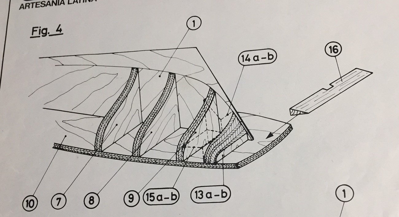
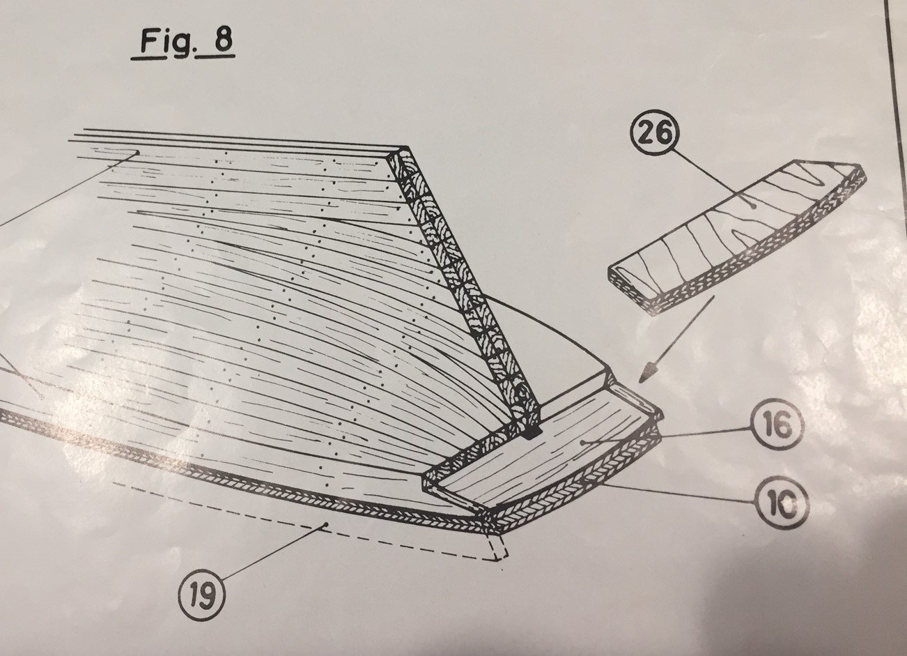
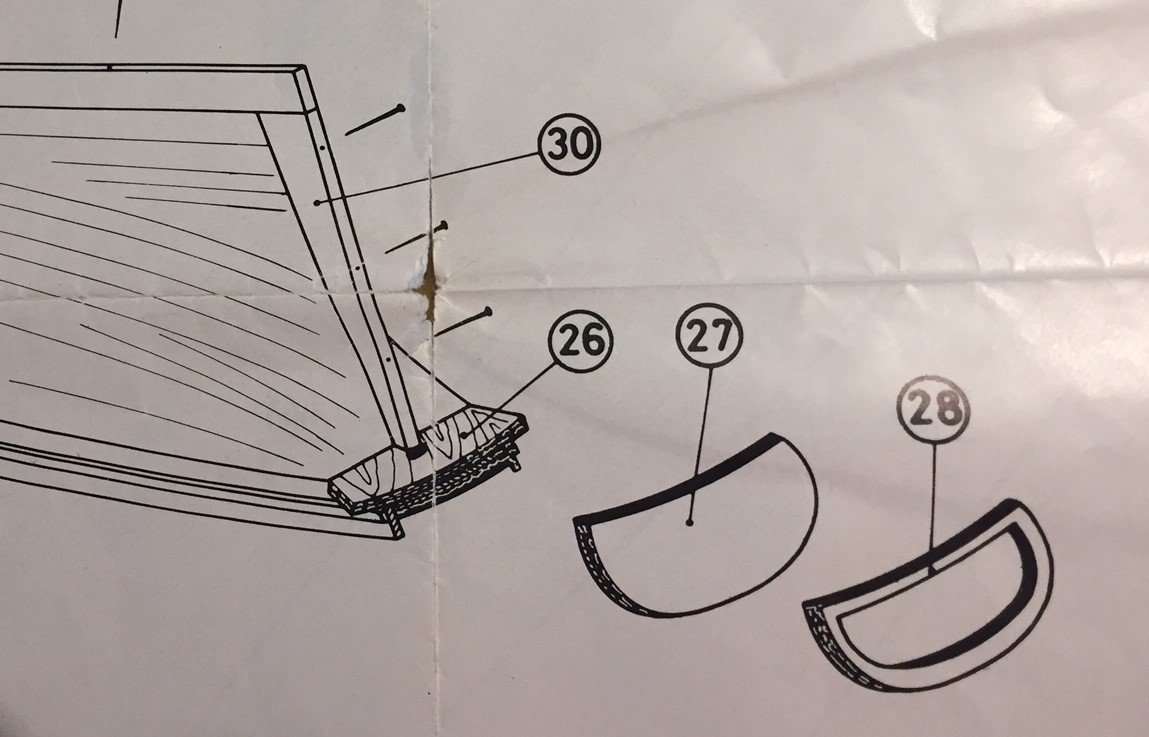
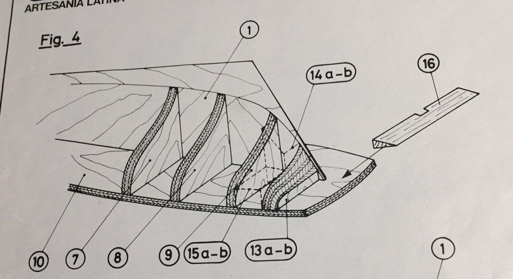
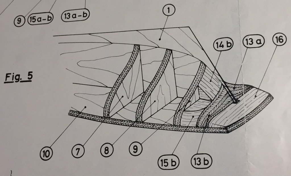
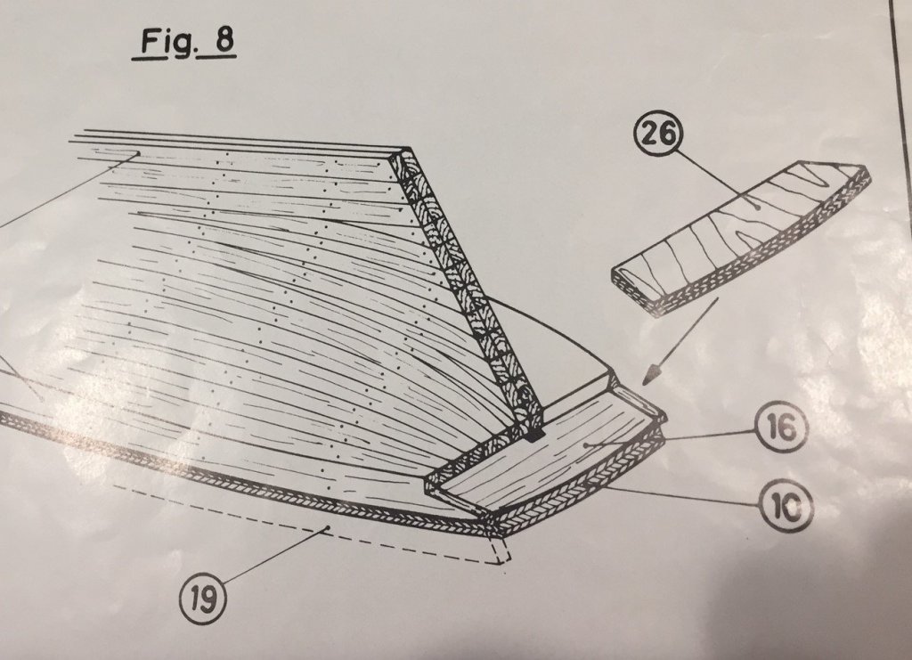
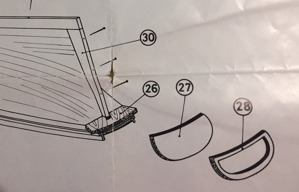
Continuing with the stern details. The plan sheets follow with what succeeded on my assembly and what did not succeed. Figure 4 shows all of the filler pieces necessary to install in the stern to help shape the drastic curvature under the counter and the foundation piece of the counter(16). This all went very well and according to the plan. Figure 5 shows the shaping necessary to have the all those filler pieces conform to the hull Plan. All was going well thus far. Figure 8 is where it went wrong. This kit was typical in its instructions to plank the hull before putting on the keel, stem and stern pieces. I installed all of them before planking the boat. I established the bearding line and provided for a rabbet. However, that did not affect the stern construction. The problem here was part #26. It was a small piece of rigid plywood that would not take up the necessary curvature or fill the space necessary to fit flush with the planking. Not to mention that that it was ugly and the plans made no mention of covering it. This is figure 9 and things then got really ugly. The instructions call for planking not only the hull but the deck prior to fitting the counter in Fig. 8 above. Here the stem, keel and stern pieces go on. The big trick here is the angle that is necessary to sand the sub deck, deck planking and the side rails(#19) to to receive the transom(#27). Not an easy task. That angle also has to be sanded to the proper curvature to receive the transom. A harder task. Soaking and bending this plywood piece was impossible. I would not take the curve. There was too much stress on the point of contact joint. With the fashion piece in place it also looked chunky and not elegant. It was also two more pieces of raw plywood. It was not going to be pretty. I have seen examples of the completed model, both here on MSW, in person from other modeler's and in Ships in Scale. In fact all the articles are in my research note book. Some have made the mistake of not placing the transom at an angle. Also, in the completed examples, including the box top, the model looked boxy and did not have the elegant appearance of Henry Rusk's drawings in Howard Chapelle's book, The History of the American Sailing ships. I had to find a better, more attractive solution.
-
What equipment stayed in the boats when stored and lashed on the davits? Not the line tub or not the two line tubs when the center board was introduced to the American Whale Boat. It/they weighed too much to be left in the floor of the boat with only 1/2 inch cedar planks. Also fixing the line in the boat was done prior to lowering the boat. For this reason the harpoons were placed in the boat prior to launching. I also believe that every thing that may have been a manufactured good was left out of the boat while stowed. Things like the lance, hatchet, boat compass, provisions and the like. Leaving such things in the boat left it exposed to the elements and potential loss. Chasing the whale did not happen instantaneously. There was time to make sure all proper equipment was on board. I agree that mast, sail, rigging, paddles, oars rudder, bailer, drogue and anything made of wood or line may have been kept in the boat. Iron and steel gets rusty and looses its edge when exposed to salt air. You can not attach the two irons to the line until the line is in the boat so why keep them there? My sources are Moby Dick, In The Heart of the Sea By Nathaniel Philbrick, Whale Ships and Whaling by Albert Cook Church
-
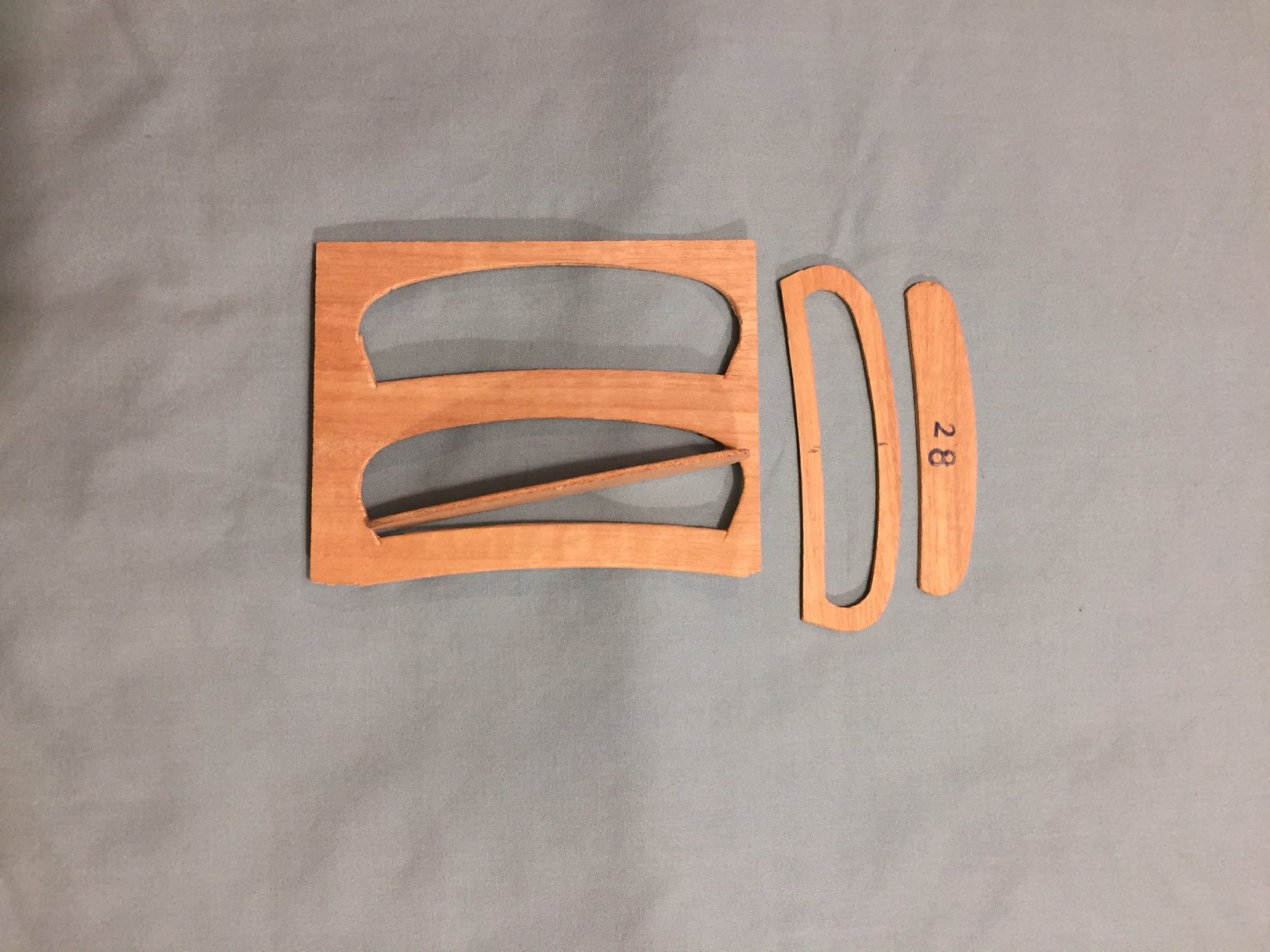
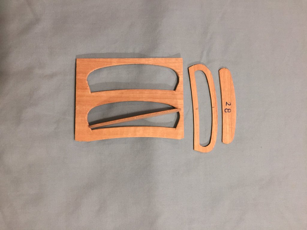
Now the stern. You can all see that I have heavily modified the stern from the kit. Looking at the kit, the kit plans and Howard Chapell's The History of American Sailing Ships, Chapter 4 on Revenue Cutters I concluded that it could not be right. Mainly, that it was unlikely to have been a solid piece of wood. I decided that most likely it would be built up on the stern timbers and then planked. The Photo's below show the parts that came in the kit. This is a 1980's kit so the parts are stamped out of plywood. This is the way the parts came on the sheet plywood. I put fin the center line to help me locate the part on the ship which I used for pattern. Here are the parts snapped out. The stern piece is on edge go you can see how thick it is. The fashion piece is next with the insert snapped out. Before deciding to build up the stern I tried to build it according to the kit. The wood was way to thick to soak and bend, plus it is plywood and may have de-laminated.

-
Steve Do not understand the term or use of the terms offcuts? God you are up late.
-
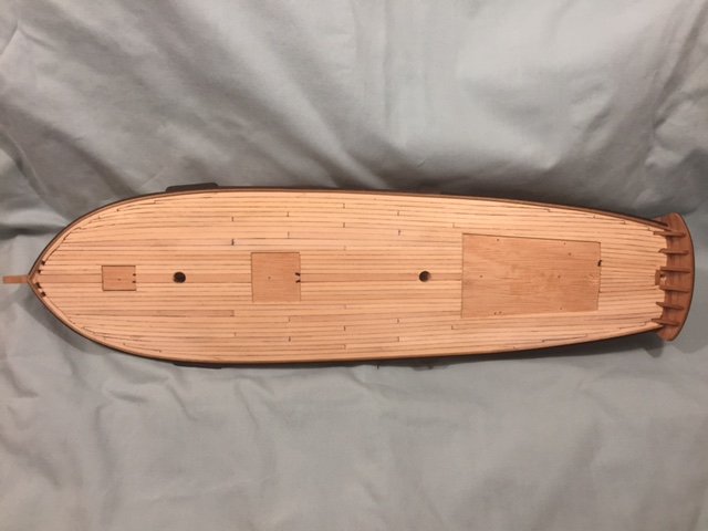
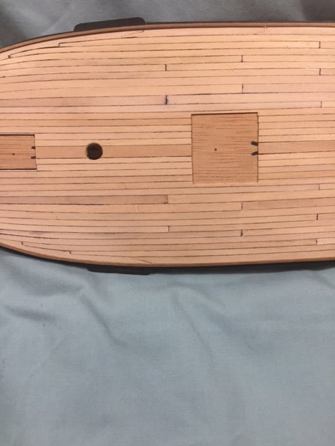
I thought I would conclude the deck section with a final photo of the deck that is completed with all the spaces ready to receive the hatches, masts and cabin. These next two photos show two of the scarf joints that are part of the margin plank.
-
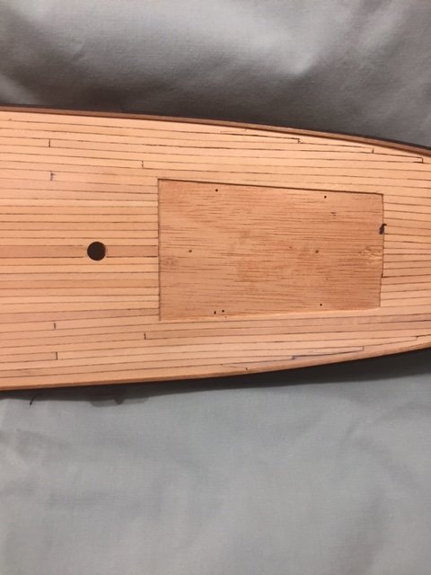
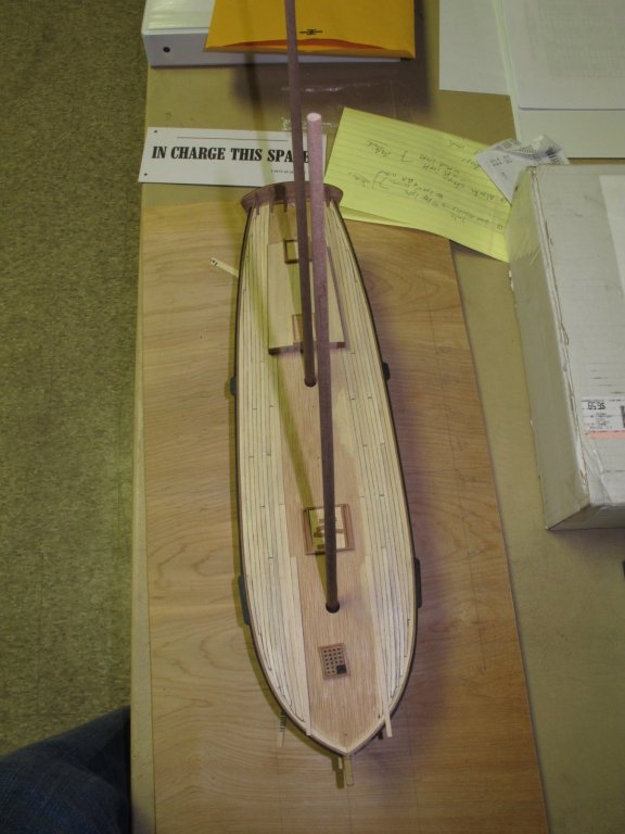
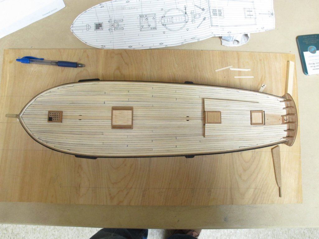
More on planking this deck. In this image I have added a few more planks port and starboard. I have been able to permanently locate the cabin. I drilled holes in the deck and used steel pins to hold it in place while I planked the deck. This allowed me plank around it without gluing it down. This was also about the time that I discovered that the planks would become more straight the closer I got the center line. I also needed to take up more space at the widest portion of the hull just abaft the foremast. You will note that the planks here are wider than the others to each side of them. I hit the books and discovered that ship decks had what is known as a binding strake. The planking is wider and thicker in these strakes than other parts of the deck. It is possible they were made from Oak also and not pine. Thus I had some authority for my choice on this deck. It was also about this time that I began thinking that I should have planked it just like the hull. However I have never seen a printed plan of a deck using stealers and drop planks. I have seen one model use a stealer in a deck. Also in the photo I have begun toying with the masts to make sure they will placed correctly. In this photo the decking is nearly complete, as are the hatches and the cabin. I decided to use a king plank at the center line of the deck. Like a binding strake a king plank is usually wider and thicker than the other planks. It to is tapered. Please note the planking of the cabin. Just about all planking plans I have seen plank the cabin on the same lines of the deck, so that is what I did. Those planks are tapered toward the stern. This photo shows the ship in the same condition except with the kit deck plan next to it. It appears smaller because it is on the building board 4 or so inches below the model deck. I succeeded in laying a deck with curved and tapered planks. No plank at its' ends was less than half the width of the plank stock used. There are only 20 plank butts in the deck, all in the center portion of the ship, 10 to port, 10 to starboard. The different colors in the deck planking was my failure to have uniform material. However, I like the look. It sort of looks weathered. I got some practice with scarf joints. The Margin plank is in 4 parts on each side. I also had practice at nibbing planks both at the stem and stern. The longest plank probably scales out to about 40 feet. Maybe a cheat, except the mainsail boom is 42 feet, and the square sail yard is 42 feet. I decided to use a 4 plank butt pattern and stuck to it for aesthetics. I like the result. The biggest fail on this deck is that I used bass wood. I used a sharpie pen to simulate the calk in the seams and it ran and was absorbed by the bass wood very badly. Especially at the butts. I did not use a pencil because it barely showed. The bass wood was not from a uniform stock, and other than the color differences it also absorbed moisture at different levels. Some of the planks became proud over time and it was necessary for me to sand the deck smooth again. The next deck I will use holly or some harder fruit wood. Further, on the next one I will use hull planking techniques and run strakes of planks on deck using the king plank as if it were the keel. I am looking for some way to chemically treat the ink to get it off. I have had some success with q-tips and alcohol and acetone. Also with a Mr. Clean Magic Eraser. That one bleached the deck also. The photos above are before any treatment to remove the ink.
-
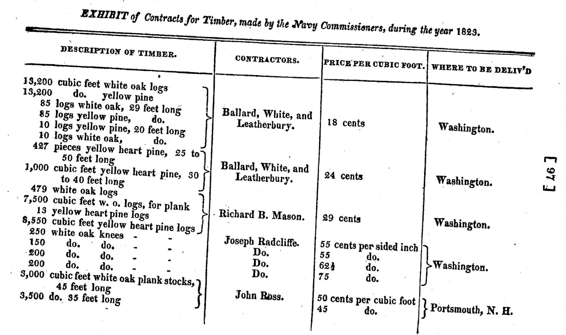
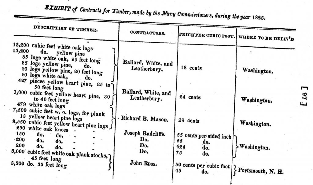
Above I stated the the idea that deck planks did not have to be cut in to 20 foot or less lengths. In the deck plan of this AL Kit the deck plank lengths are about 17 feet. I set out to prove that greater lengths of plank were available in the United States. I was fortunate enough to come across a document submitted to Congress that was a report of the contracts of the Navy for 1823. EXHIBIT of Contracts for Timber, made by the Navy Commissioners, during the year 1823. The document proves that there was plenty of timber bought that was more than 20 feet long. Most of this timber was more than 20 feet long. How long do you think a log may be? Most important to our discussions is the fact that there are white oak logs, and yellow pine that are 29 feet long. Yellow heart pine that is 25 to 50 feet long and white oak plank stocks that are 35 and 45 feet long. Also note that the majority of the timber was delivered to the Washington Navy yard, with some going to Portsmouth, N.H. Which means it was perhaps transported some distance. These contracts were entered into 8 years after the War Of 1812 ended and the building of those first replacement Revenue Cutters in 1815.
-
Did all topsail schooners have ratlines on both masts?
roach101761 replied to Cathead's topic in Masting, rigging and sails
Eric They may not have had ratlines and it is most likely that they climbed the hoops to the tops when it was necessary. I concluded this two years ago with my build to the AL kit Dallas. I have recently started a thread on my build using some photo's i had in the early stages of the model. I also started a thread on setting a topsail flying. Here is the link. Frank's memory is pretty good in remembering this thread. He actually posted a video of the HMS Surprise hoisting the a sail flying. -
I just managed to insert the attachments of the deck plan in the kit so that it appears as an image. So go back above and check it out.
-
In the last post I did not manage to insert the opened deck plan views. I will edit it shortly when I figure that out.
-
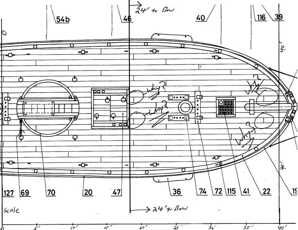
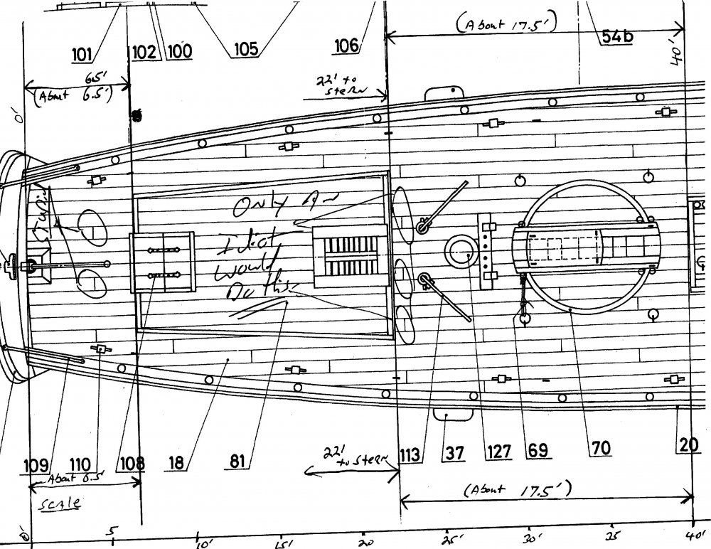
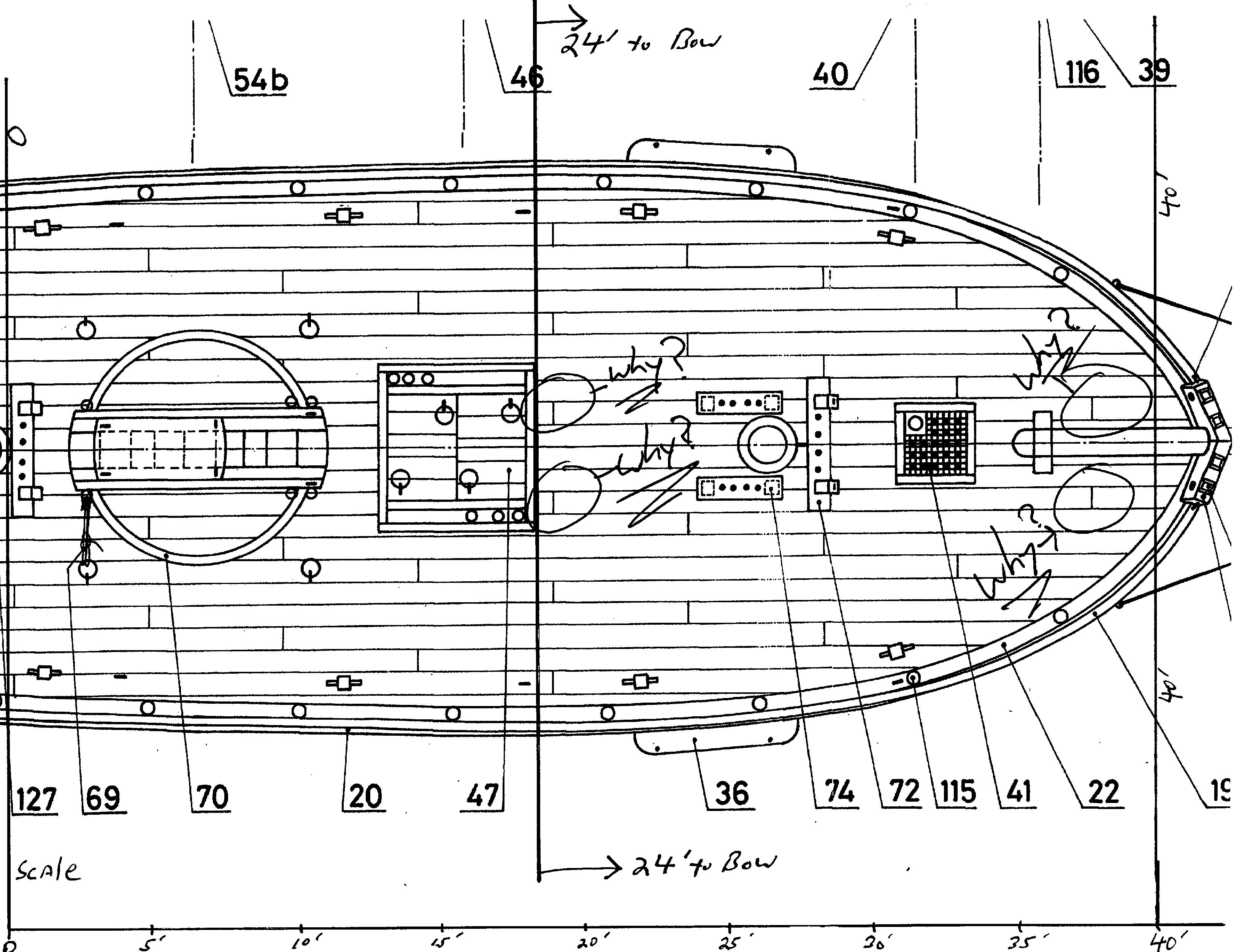
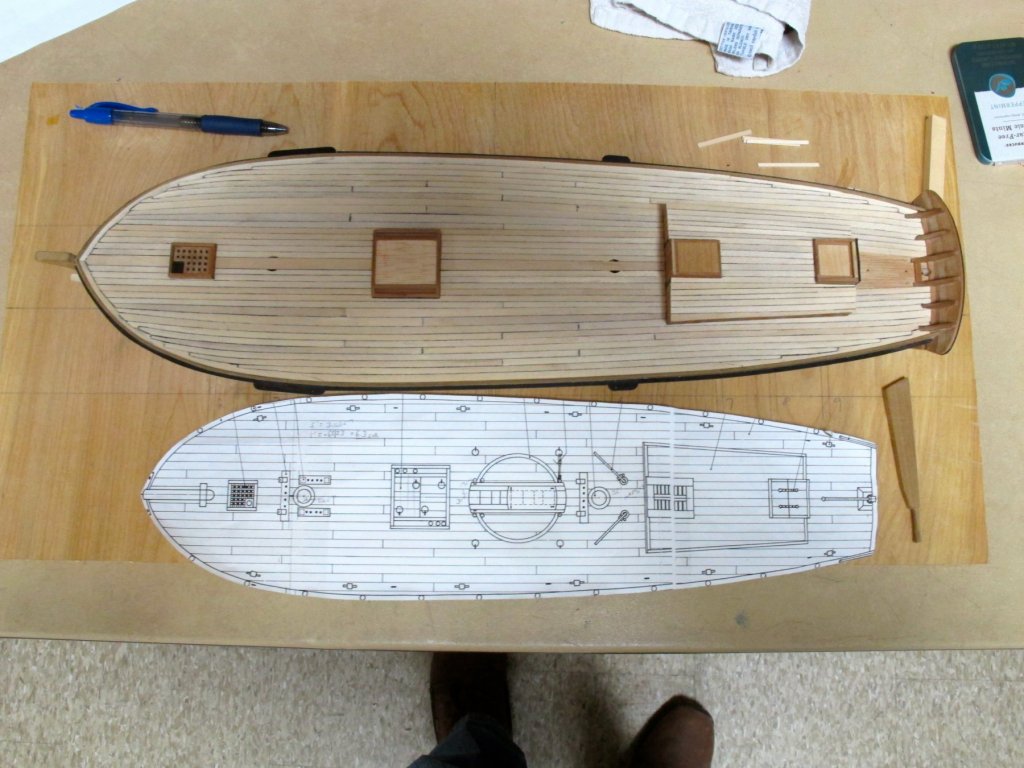
Deck Planking in American ships prior to 1820. In a post above I advised that I was a believer in the theory that deck planks were curved and tapered. Especially in American Ships where the timber was readily available everywhere. Lloyd McCaffery published an article in the Nautical Research Journal in Vol 53, No. 4 Winter 2008. He made the case that in earlier ships, hacking the deck planks into 20 foot planks and adhering to a strict pattern was not the norm until very late in the age of sail. It perhaps appeared earlier in English ships as their timber supplies became very limited and had to import most of their timber. He makes several points to support his argument. Among those points is that the timber itself is tapered and the shipwrights would have taken advantage of this natural feature. He also states that straight run decks did not appear until the early 1800's. He presented several examples where the planks were curved, tapered and varied in width. Intuitively I felt his thesis was correct, especially in American built craft where timber was always abundant in the age of sail. Further, in small ships it seemed to make the most sense. I also began to notice how ridiculous adhering to a straight laid deck with a rigid pattern may be. This Kit that is not the Dallas represents the large 79/80 ton large cutter design by William Doughty. The following are some key design features. Length on deck 69'6'' Main mast 64' Fore mast 62' Square sail yard 40' Boom 42' I give these dimensions to show that very long timbers, exceeding 25 feet were readily available. They did not need to be transported by ship, but could be rafted down river or towed to the ship yard. Or travel over land with ox drawn conveyances. Now look at the deck plan of the kit Dallas and you will readily observe how stupid the deck layout is drawn. When you look at these two attachments please remember the whole deck is only 69'6". Two 35 foot planks could be laid to cover the entire uninterrupted deck from rudder post to the tip of the deck at the bow. Also remember that the data of the ship given above shows that timber more than 40 feet long was readily available. Please note the scale I have superimposed on the deck plan at 5' intervals and the measured distances between major deck furniture. The distance between the stern and cabin trunk is only about 6 feet. Why on earth would you cut that deck plank into a 4 foot section and 2 foot section? Plank butts are places for water to intrude and are a weak point in the deck. Those two butts should be eliminated. The third one in the stern should go as well because the plank terminates at the cabin trunk at about 15 feet. Next, check out the three butts at the forward end of the cabin trunk that are one foot in length from the the cabin. How stupid is that? Especially since the distance to the main hatch is only about 17.5 feet from the cabin trunk. The forward part of the main hatch to the furthermost point of the bow is only 24 feet and rapidly diminishes as the deck sweeps aft. Also, look at the obstructions of both masts, main hatch and forward hatch. Many of the butts should be eliminated, not just the ones I marked to show my point. I decided a new decking pattern and plan for the deck was in order, using longer lengths of plank and not hacking it into 20 foot sections. Actually this deck plan cuts the planking into lengths approximately 17 feet long. A greater sin. Take a look. Shortly I will have additional comments on how I laid out my deck.